JP7371010B2 - rotating connector device - Google Patents
rotating connector device Download PDFInfo
- Publication number
- JP7371010B2 JP7371010B2 JP2020559876A JP2020559876A JP7371010B2 JP 7371010 B2 JP7371010 B2 JP 7371010B2 JP 2020559876 A JP2020559876 A JP 2020559876A JP 2020559876 A JP2020559876 A JP 2020559876A JP 7371010 B2 JP7371010 B2 JP 7371010B2
- Authority
- JP
- Japan
- Prior art keywords
- wall
- connector device
- stator
- rotary connector
- maximum length
- Prior art date
- Legal status (The legal status is an assumption and is not a legal conclusion. Google has not performed a legal analysis and makes no representation as to the accuracy of the status listed.)
- Active
Links
- 230000004308 accommodation Effects 0.000 claims description 57
- 230000002093 peripheral effect Effects 0.000 claims description 20
- 230000007613 environmental effect Effects 0.000 description 13
- 230000008878 coupling Effects 0.000 description 6
- 238000010168 coupling process Methods 0.000 description 6
- 238000005859 coupling reaction Methods 0.000 description 6
- 230000014509 gene expression Effects 0.000 description 5
- 239000007788 liquid Substances 0.000 description 4
- 238000005516 engineering process Methods 0.000 description 3
- 239000012790 adhesive layer Substances 0.000 description 2
- 230000000295 complement effect Effects 0.000 description 1
- 230000000694 effects Effects 0.000 description 1
- 230000004048 modification Effects 0.000 description 1
- 238000012986 modification Methods 0.000 description 1
Images


Classifications
-
- H—ELECTRICITY
- H01—ELECTRIC ELEMENTS
- H01R—ELECTRICALLY-CONDUCTIVE CONNECTIONS; STRUCTURAL ASSOCIATIONS OF A PLURALITY OF MUTUALLY-INSULATED ELECTRICAL CONNECTING ELEMENTS; COUPLING DEVICES; CURRENT COLLECTORS
- H01R35/00—Flexible or turnable line connectors, i.e. the rotation angle being limited
- H01R35/04—Turnable line connectors with limited rotation angle with frictional contact members
-
- B—PERFORMING OPERATIONS; TRANSPORTING
- B60—VEHICLES IN GENERAL
- B60R—VEHICLES, VEHICLE FITTINGS, OR VEHICLE PARTS, NOT OTHERWISE PROVIDED FOR
- B60R16/00—Electric or fluid circuits specially adapted for vehicles and not otherwise provided for; Arrangement of elements of electric or fluid circuits specially adapted for vehicles and not otherwise provided for
- B60R16/02—Electric or fluid circuits specially adapted for vehicles and not otherwise provided for; Arrangement of elements of electric or fluid circuits specially adapted for vehicles and not otherwise provided for electric constitutive elements
- B60R16/023—Electric or fluid circuits specially adapted for vehicles and not otherwise provided for; Arrangement of elements of electric or fluid circuits specially adapted for vehicles and not otherwise provided for electric constitutive elements for transmission of signals between vehicle parts or subsystems
- B60R16/027—Electric or fluid circuits specially adapted for vehicles and not otherwise provided for; Arrangement of elements of electric or fluid circuits specially adapted for vehicles and not otherwise provided for electric constitutive elements for transmission of signals between vehicle parts or subsystems between relatively movable parts of the vehicle, e.g. between steering wheel and column
-
- H—ELECTRICITY
- H01—ELECTRIC ELEMENTS
- H01R—ELECTRICALLY-CONDUCTIVE CONNECTIONS; STRUCTURAL ASSOCIATIONS OF A PLURALITY OF MUTUALLY-INSULATED ELECTRICAL CONNECTING ELEMENTS; COUPLING DEVICES; CURRENT COLLECTORS
- H01R13/00—Details of coupling devices of the kinds covered by groups H01R12/70 or H01R24/00 - H01R33/00
- H01R13/66—Structural association with built-in electrical component
-
- H—ELECTRICITY
- H01—ELECTRIC ELEMENTS
- H01R—ELECTRICALLY-CONDUCTIVE CONNECTIONS; STRUCTURAL ASSOCIATIONS OF A PLURALITY OF MUTUALLY-INSULATED ELECTRICAL CONNECTING ELEMENTS; COUPLING DEVICES; CURRENT COLLECTORS
- H01R13/00—Details of coupling devices of the kinds covered by groups H01R12/70 or H01R24/00 - H01R33/00
- H01R13/72—Means for accommodating flexible lead within the holder
-
- H—ELECTRICITY
- H02—GENERATION; CONVERSION OR DISTRIBUTION OF ELECTRIC POWER
- H02G—INSTALLATION OF ELECTRIC CABLES OR LINES, OR OF COMBINED OPTICAL AND ELECTRIC CABLES OR LINES
- H02G11/00—Arrangements of electric cables or lines between relatively-movable parts
-
- B—PERFORMING OPERATIONS; TRANSPORTING
- B62—LAND VEHICLES FOR TRAVELLING OTHERWISE THAN ON RAILS
- B62D—MOTOR VEHICLES; TRAILERS
- B62D1/00—Steering controls, i.e. means for initiating a change of direction of the vehicle
- B62D1/02—Steering controls, i.e. means for initiating a change of direction of the vehicle vehicle-mounted
- B62D1/04—Hand wheels
- B62D1/10—Hubs; Connecting hubs to steering columns, e.g. adjustable
-
- H—ELECTRICITY
- H01—ELECTRIC ELEMENTS
- H01R—ELECTRICALLY-CONDUCTIVE CONNECTIONS; STRUCTURAL ASSOCIATIONS OF A PLURALITY OF MUTUALLY-INSULATED ELECTRICAL CONNECTING ELEMENTS; COUPLING DEVICES; CURRENT COLLECTORS
- H01R2201/00—Connectors or connections adapted for particular applications
- H01R2201/26—Connectors or connections adapted for particular applications for vehicles
-
- H—ELECTRICITY
- H02—GENERATION; CONVERSION OR DISTRIBUTION OF ELECTRIC POWER
- H02G—INSTALLATION OF ELECTRIC CABLES OR LINES, OR OF COMBINED OPTICAL AND ELECTRIC CABLES OR LINES
- H02G11/00—Arrangements of electric cables or lines between relatively-movable parts
- H02G11/02—Arrangements of electric cables or lines between relatively-movable parts using take-up reel or drum
Landscapes
- Engineering & Computer Science (AREA)
- Mechanical Engineering (AREA)
- Motor Or Generator Frames (AREA)
- Electric Cable Arrangement Between Relatively Moving Parts (AREA)
- Details Of Connecting Devices For Male And Female Coupling (AREA)
- Steering Controls (AREA)
Description
本願に開示される技術は、回転コネクタ装置に関する。 The technology disclosed in this application relates to a rotary connector device.
車両に用いられる回転コネクタ装置が知られている(例えば、特許文献1を参照)。 A rotary connector device used in a vehicle is known (see, for example, Patent Document 1).
回転コネクタ装置を様々な車両に対応させるために、回転コネクタ装置の耐環境性を高めることが好ましい。 In order to make the rotary connector device compatible with various vehicles, it is preferable to improve the environmental resistance of the rotary connector device.
本願に開示される技術の課題は、回転コネクタ装置の耐環境性を高めることにある。 An object of the technology disclosed in this application is to improve the environmental resistance of a rotary connector device.
第1の特徴に係る回転コネクタ装置はステータおよび回転体を備えている。ステータは、第1ステータ本体と、第1ステータ本体とは別部材であって第1ステータ本体に連結された第2ステータ本体と、を含んでいる。回転体は、ステータに対して回転軸線回りに回転可能に設けられている。ステータおよび回転体は、回転軸線を取り囲むように設けられたケーブル収容空間をステータおよび回転体の間に画定している。第2ステータ本体は、回転軸線に平行な軸方向に沿って延びた第1壁と、軸方向に沿って延び回転軸線に垂直な径方向において第1壁と間隔を空けて配置された第2壁と、を含んでいる。第1壁は径方向においてケーブル収容空間および第2壁の間に配置されている。第1ステータ本体は、軸方向に沿って延び径方向において第1壁および第2壁の間に配置された中間壁を含んでいる。 The rotary connector device according to the first feature includes a stator and a rotating body. The stator includes a first stator main body and a second stator main body that is a separate member from the first stator main body and is connected to the first stator main body. The rotating body is provided to be rotatable about the rotation axis with respect to the stator. The stator and the rotating body define a cable accommodation space between the stator and the rotating body, which is provided so as to surround the axis of rotation. The second stator body includes a first wall extending along an axial direction parallel to the rotational axis, and a second wall extending along the axial direction and spaced apart from the first wall in a radial direction perpendicular to the rotational axis. Contains walls and. The first wall is arranged radially between the cable receiving space and the second wall. The first stator body includes an intermediate wall extending along the axial direction and disposed between the first wall and the second wall in the radial direction.
第1の特徴に係る回転コネクタ装置では、第1ステータ本体の中間壁が径方向において第1壁および第2壁の間に配置されているので、ステータの外側からケーブル収容空間までの経路が長くなる。したがって、ステータの外側からケーブル収容空間に異物が侵入しにくくなり、回転コネクタ装置の耐環境性を高めることができる。 In the rotary connector device according to the first feature, since the intermediate wall of the first stator body is arranged between the first wall and the second wall in the radial direction, the path from the outside of the stator to the cable accommodation space is long. Become. Therefore, foreign matter is less likely to enter the cable accommodation space from outside the stator, and the environmental resistance of the rotary connector device can be improved.
第2の特徴に係る回転コネクタ装置は、第1の特徴に係る回転コネクタ装置において、中間壁は軸方向に沿って延びている。 A rotary connector device according to a second feature is the rotary connector device according to the first feature, in which the intermediate wall extends in the axial direction.
第2の特徴に係る回転コネクタ装置では、第1壁がケーブル収容空間を少なくとも部分的に画定しているので、回転コネクタ装置の大型化を抑制しつつ回転コネクタ装置の耐環境性を高めることができる。 In the rotary connector device according to the second feature, since the first wall at least partially defines the cable accommodation space, it is possible to increase the environmental resistance of the rotary connector device while suppressing the increase in size of the rotary connector device. can.
第3の特徴に係る回転コネクタ装置は、第1または第2の特徴に係る回転コネクタ装置において、第1壁および第2壁は径方向においてケーブル収容空間の外側に配置されている。 A rotary connector device according to a third feature is the rotary connector device according to the first or second feature, in which the first wall and the second wall are arranged outside the cable accommodation space in the radial direction.
第3の特徴に係る回転コネクタ装置では、第1壁および第2壁が径方向においてケーブル収容空間の外側に配置されているので、外部に露出しやすい回転コネクタ装置の外周部の耐環境性を高めることができる。 In the rotary connector device according to the third feature, the first wall and the second wall are arranged outside the cable accommodation space in the radial direction, so that the environmental resistance of the outer peripheral portion of the rotary connector device that is easily exposed to the outside is improved. can be increased.
第4の特徴に係る回転コネクタ装置は、第1~第3の特徴のいずれかに係る回転コネクタ装置において、第1壁は、径方向に画定された第1最大厚みと、軸方向に画定された第1最大長さと、を有している。第1最大長さは、第1最大厚みよりも大きい。 A rotary connector device according to a fourth feature is a rotary connector device according to any one of the first to third features, wherein the first wall has a first maximum thickness defined in the radial direction and a first maximum thickness defined in the axial direction. and a first maximum length. The first maximum length is greater than the first maximum thickness.
第3の特徴に係る回転コネクタ装置では、第1最大長さが第1最大厚みよりも大きいので、ステータの外側からケーブル収容空間までの経路をさらに長くできる。 In the rotary connector device according to the third feature, since the first maximum length is greater than the first maximum thickness, the path from the outside of the stator to the cable accommodation space can be further lengthened.
第5の特徴に係る回転コネクタ装置は、第1~第4の特徴のいずれかに係る回転コネクタ装置において、第2壁は、径方向に画定された第2最大厚みと、軸方向に画定された第2最大長さと、を有している。第2最大長さは、第2最大厚みよりも大きい。 A rotary connector device according to a fifth feature is a rotary connector device according to any one of the first to fourth features, wherein the second wall has a second maximum thickness defined in the radial direction and a second maximum thickness defined in the axial direction. and a second maximum length. The second maximum length is greater than the second maximum thickness.
第5の特徴に係る回転コネクタ装置では、第2最大長さが第2最大厚みよりも大きいので、ステータの外側からケーブル収容空間までの経路をさらに長くできる。 In the rotary connector device according to the fifth feature, since the second maximum length is greater than the second maximum thickness, the path from the outside of the stator to the cable accommodation space can be further lengthened.
第6の特徴に係る回転コネクタ装置は、第1~第5の特徴のいずれかに係る回転コネクタ装置において、中間壁は、径方向に画定された第3最大厚みと、軸方向に画定された第3最大長さと、を有している。第3最大長さは、第3最大厚みよりも大きい。 A rotary connector device according to a sixth feature is a rotary connector device according to any one of the first to fifth features, wherein the intermediate wall has a third maximum thickness defined in the radial direction and a third maximum thickness defined in the axial direction. and a third maximum length. The third maximum length is greater than the third maximum thickness.
第6の特徴に係る回転コネクタ装置では、第3最大長さが第3最大厚みよりも大きいので、ステータの外側からケーブル収容空間までの経路をさらに長くできる。 In the rotary connector device according to the sixth feature, since the third maximum length is greater than the third maximum thickness, the path from the outside of the stator to the cable accommodation space can be further lengthened.
第7の特徴に係る回転コネクタ装置は、第1~第6の特徴のいずれかに係る回転コネクタ装置において、第2ステータ本体は、径方向において第1壁および第2壁の間に設けられた中間溝を含んでいる。中間壁は、中間溝内に配置されている。 A rotary connector device according to a seventh feature is a rotary connector device according to any one of the first to sixth features, in which the second stator body is provided between the first wall and the second wall in the radial direction. Contains an intermediate groove. The intermediate wall is disposed within the intermediate groove.
第7の特徴に係る回転コネクタ装置では、中間壁が中間溝内に配置されているので、ステータの外側からケーブル収容空間までの経路にラビリンス構造を形成することができる。 In the rotary connector device according to the seventh feature, since the intermediate wall is disposed within the intermediate groove, a labyrinth structure can be formed in the path from the outside of the stator to the cable accommodation space.
第8の特徴に係る回転コネクタ装置は、第7の特徴に係る回転コネクタ装置において、第2ステータ本体は、第1壁を第2壁に連結する連結部を含んでいる。中間溝は、第1壁、第2壁、および連結部により画定されている。 The rotary connector device according to an eighth feature is the rotary connector device according to the seventh feature, in which the second stator main body includes a connecting portion that connects the first wall to the second wall. The intermediate groove is defined by the first wall, the second wall, and the connecting portion.
第8の特徴に係る回転コネクタ装置では、中間溝が第1壁、第2壁、および連結部により画定されているので、ステータの外側からケーブル収容空間までの経路にラビリンス構造を確実に形成することができる。 In the rotary connector device according to the eighth feature, since the intermediate groove is defined by the first wall, the second wall, and the connecting portion, a labyrinth structure is reliably formed in the path from the outside of the stator to the cable accommodation space. be able to.
第9の特徴に係る回転コネクタ装置は、第1~第8の特徴のいずれかに係る回転コネクタ装置において、第1壁および第2壁のうち少なくとも1つは、径方向において中間壁と接触可能である。 A rotary connector device according to a ninth feature is a rotary connector device according to any one of the first to eighth features, in which at least one of the first wall and the second wall is capable of contacting the intermediate wall in the radial direction. It is.
第9の特徴に係る回転コネクタ装置では、第1壁および第2壁のうち少なくとも1つが径方向において中間壁と接触可能である。したがって、ステータの外側からケーブル収容空間までの経路を狭くすることができ、回転コネクタ装置の耐環境性をさらに高めることができる。 In the rotary connector device according to the ninth feature, at least one of the first wall and the second wall can contact the intermediate wall in the radial direction. Therefore, the path from the outside of the stator to the cable accommodation space can be narrowed, and the environmental resistance of the rotary connector device can be further improved.
第10の特徴に係る回転コネクタ装置は、第1~第9の特徴のいずれかに係る回転コネクタ装置において、第1壁、第2壁、および中間壁のうち少なくとも1つは、回転軸線回りに画定された周方向に沿って延びている。 A rotary connector device according to a tenth feature is a rotary connector device according to any one of the first to ninth features, in which at least one of the first wall, the second wall, and the intermediate wall rotates around the rotation axis. It extends along the defined circumferential direction.
第10の特徴に係る回転コネクタ装置では、第1壁、第2壁、および中間壁のうち少なくとも1つが回転軸線回りに画定された周方向に沿って延びているので、ステータの外側からケーブル収容空間までの経路が長くなる範囲を周方向に広く確保できる。これにより、回転コネクタ装置の耐環境性をさらに高めることができる。 In the rotary connector device according to the tenth feature, at least one of the first wall, the second wall, and the intermediate wall extends along the circumferential direction defined around the rotation axis, so that the cable can be accommodated from the outside of the stator. It is possible to secure a wide range in the circumferential direction in which the path to the space is long. Thereby, the environmental resistance of the rotary connector device can be further improved.
第11の特徴に係る回転コネクタ装置は、第10の特徴に係る回転コネクタ装置において、第1壁、第2壁、および中間壁のうち少なくとも1つは、周方向において90度以上にわたって延びている。 In the rotary connector device according to the eleventh feature, in the rotary connector device according to the tenth feature, at least one of the first wall, the second wall, and the intermediate wall extends over 90 degrees or more in the circumferential direction. .
第11の特徴に係る回転コネクタ装置では、第1壁、第2壁、および中間壁のうち少なくとも1つが周方向において90度以上にわたって延びているので、ステータの外側からケーブル収容空間までの経路が長くなる範囲を周方向に確実に広く確保できる。 In the rotary connector device according to the eleventh feature, at least one of the first wall, the second wall, and the intermediate wall extends over 90 degrees in the circumferential direction, so that the path from the outside of the stator to the cable accommodation space is It is possible to reliably secure a wide range of length in the circumferential direction.
第12の特徴に係る回転コネクタ装置は、第11の特徴に係る回転コネクタ装置において、第1壁、第2壁、および中間壁のうち少なくとも1つは、周方向において180度以上にわたって延びている。 The rotary connector device according to the twelfth feature is the rotary connector device according to the eleventh feature, wherein at least one of the first wall, the second wall, and the intermediate wall extends over 180 degrees or more in the circumferential direction. .
第12の特徴に係る回転コネクタ装置では、第1壁、第2壁、および中間壁のうち少なくとも1つが周方向において180度以上にわたって延びているので、ステータの外側からケーブル収容空間までの経路が長くなる範囲を周方向により確実に広く確保できる。 In the rotary connector device according to the twelfth feature, at least one of the first wall, the second wall, and the intermediate wall extends over 180 degrees in the circumferential direction, so that the path from the outside of the stator to the cable accommodation space is It is possible to reliably secure a wider range in the circumferential direction.
第13の特徴に係る回転コネクタ装置は、第1~第12の特徴のいずれかに係る回転コネクタ装置において、第1ステータ本体は、ケーブル収容空間を少なくとも部分的に画定するベースプレートと、ベースプレートから軸方向に沿って延び径方向において中間壁と間隔を空けて配置された連結体と、を含んでいる。第2壁は、径方向において中間壁および連結体の間に配置されている。 A rotary connector device according to a thirteenth feature is a rotary connector device according to any one of the first to twelfth features, in which the first stator body includes a base plate that at least partially defines a cable accommodation space, and a shaft extending from the base plate. a coupling body extending along the direction and spaced apart from the intermediate wall in the radial direction. The second wall is radially disposed between the intermediate wall and the connector.
第13の特徴に係る回転コネクタ装置では、第2壁が径方向において中間壁および連結体の間に配置されているので、第2壁の外側からケーブル収容空間までの経路を長くしつつ、連結体の連結強度を高めることができる。 In the rotary connector device according to the thirteenth feature, since the second wall is arranged between the intermediate wall and the connecting body in the radial direction, the route from the outside of the second wall to the cable accommodation space is lengthened, and the connection It can increase the strength of connections in the body.
第14の特徴に係る回転コネクタ装置は、第13の特徴に係る回転コネクタ装置において、第2ステータ本体は、第2壁から径方向外側に突出する突起を含んでいる。連結体は、第2ステータ本体を第1ステータ本体に連結するように突起に接触可能である。 A rotary connector device according to a fourteenth feature is the rotary connector device according to the thirteenth feature, in which the second stator body includes a protrusion that projects radially outward from the second wall. The coupling body is contactable with the protrusion to couple the second stator body to the first stator body.
第14の特徴に係る回転コネクタ装置では、第2ステータ本体を第1ステータ本体に連結するように連結体が突起に接触可能であるので、第2ステータ本体および第1ステータ本体の連結強度をさらに高めることができる。 In the rotary connector device according to the fourteenth feature, since the connecting body can contact the protrusion to connect the second stator body to the first stator body, the connection strength between the second stator body and the first stator body is further increased. can be increased.
第15の特徴に係る回転コネクタ装置は、第13または第14の特徴に係る回転コネクタ装置において、第2壁は、外周面と、外周面に設けられた外側凹部と、を含んでいる。連結体は、外側凹部内に配置されている。 A rotary connector device according to a fifteenth feature is the rotary connector device according to the thirteenth or fourteenth feature, in which the second wall includes an outer circumferential surface and an outer recess provided in the outer circumferential surface. The coupling body is disposed within the outer recess.
第15の特徴に係る回転コネクタ装置では、連結体が外側凹部内に配置されているので、ステータの大型化を抑制しつつ第1ステータ本体および第2ステータ本体の連結強度を高めることができる。 In the rotary connector device according to the fifteenth feature, since the connecting body is disposed within the outer recess, it is possible to increase the connection strength between the first stator main body and the second stator main body while suppressing an increase in the size of the stator.
第16の特徴に係る回転コネクタ装置は、第15の特徴に係る回転コネクタ装置において、中間壁は、中間外周面と、中間外周面に設けられた中間凹部と、を含んでいる。中間凹部は、外側凹部の径方向内側に配置されている。 A rotary connector device according to a sixteenth feature is the rotary connector device according to the fifteenth feature, in which the intermediate wall includes an intermediate outer circumferential surface and an intermediate recess provided in the intermediate outer circumferential surface. The intermediate recess is arranged radially inward of the outer recess.
第16の特徴に係る回転コネクタ装置では、中間凹部が外側凹部の径方向内側に配置されているので、ステータの大型化を抑制しつつ、ステータの外側からケーブル収容空間までの経路を長くできる。 In the rotary connector device according to the sixteenth feature, since the intermediate recess is arranged radially inside the outer recess, the path from the outside of the stator to the cable accommodation space can be lengthened while suppressing the stator from increasing in size.
第17の特徴に係る回転コネクタ装置は、第16の特徴に係る回転コネクタ装置において、第2壁は、中間凹部内に配置された突出部を含んでいる。 A rotary connector device according to a seventeenth feature is the rotary connector device according to the sixteenth feature, wherein the second wall includes a protrusion disposed within the intermediate recess.
第17の特徴に係る回転コネクタ装置では、第2壁が中間凹部内に配置された突出部を含んでいるので、第1ステータ本体および第2ステータ本体の周方向の位置決めが容易となる。 In the rotary connector device according to the seventeenth feature, since the second wall includes the protrusion disposed within the intermediate recess, circumferential positioning of the first stator body and the second stator body is facilitated.
第18の特徴に係る回転コネクタ装置は、第1~第15の特徴のいずれかに係る回転コネクタ装置において、中間壁は、中間外周面と、中間外周面に設けられた中間凹部と、を含んでいる。第2壁は、中間凹部内に配置された突出部を含んでいる。 A rotary connector device according to an eighteenth feature is a rotary connector device according to any one of the first to fifteenth features, wherein the intermediate wall includes an intermediate outer circumferential surface and an intermediate recess provided in the intermediate outer circumferential surface. I'm here. The second wall includes a protrusion disposed within the intermediate recess.
第18の特徴に係る回転コネクタ装置では、第2壁が中間凹部内に配置された突出部を含んでいるので、第1ステータ本体および第2ステータ本体の周方向の位置決めが容易となる。 In the rotary connector device according to the eighteenth feature, since the second wall includes the protrusion disposed within the intermediate recess, circumferential positioning of the first stator body and the second stator body is facilitated.
第19の特徴に係る回転コネクタ装置は、第1~第12の特徴のいずれかに係る回転コネクタ装置において、第1ステータ本体は、外周部を有しケーブル収容空間を少なくとも部分的に画定するベースプレートを含んでいる。中間壁は、ベースプレートの外周部から軸方向に沿って延びている。 A rotary connector device according to a nineteenth feature is a rotary connector device according to any one of the first to twelfth features, in which the first stator body has a base plate having an outer peripheral portion and at least partially defining a cable accommodation space. Contains. The intermediate wall extends along the axial direction from the outer periphery of the base plate.
第19の特徴に係る回転コネクタ装置では、中間壁がベースプレートの外周部から軸方向に沿って延びているので、ケーブル収容空間を広く確保しつつ、ステータの外側からケーブル収容空間までの経路を長くできる。 In the rotary connector device according to the nineteenth feature, since the intermediate wall extends along the axial direction from the outer peripheral part of the base plate, a wide cable accommodation space is secured, and a route from the outside of the stator to the cable accommodation space is lengthened. can.
第20の特徴に係る回転コネクタ装置は、第1~第19の特徴のいずれかに係る回転コネクタ装置において、ステータを車両本体に搭載した場合に、中間壁の少なくとも一部は、回転軸線よりも上側に配置される。 A rotary connector device according to a twentieth feature is a rotary connector device according to any one of the first to nineteenth features, in which when the stator is mounted on a vehicle body, at least a portion of the intermediate wall is lower than the rotation axis. placed on the top.
第20の特徴に係る回転コネクタ装置では、ステータを車両本体に搭載した状態で、例えば液体が回転コネクタ装置にこぼれても、中間壁により液体のケーブル収容空間への侵入を確実に抑制できる。 In the rotary connector device according to the twentieth feature, even if, for example, liquid spills onto the rotary connector device while the stator is mounted on the vehicle body, the intermediate wall can reliably prevent the liquid from entering the cable accommodation space.
第21の特徴に係る回転コネクタ装置は、第1~第20の特徴のいずれかに係る回転コネクタ装置において、第1壁は、軸方向に画定された第1最大長さを有している。第2壁は、軸方向に画定された第2最大長さを有している。中間壁は、軸方向に画定された第3最大長さを有している。第1最大長さおよび第2最大長さのうち少なくとも1つは、第3最大長さよりも長い。 A rotary connector device according to a twenty-first feature is a rotary connector device according to any one of the first to twentieth features, wherein the first wall has a first maximum length defined in the axial direction. The second wall has a second maximum length defined in the axial direction. The intermediate wall has a third maximum length defined in the axial direction. At least one of the first maximum length and the second maximum length is longer than the third maximum length.
第21の特徴に係る回転コネクタ装置では、第1壁および第2壁のうち少なくとも1つと中間壁との間の隙間の長さをより長く確保できる。 In the rotary connector device according to the twenty-first feature, it is possible to ensure a longer gap between at least one of the first wall and the second wall and the intermediate wall.
第22の特徴に係る回転コネクタ装置は、第1~第21の特徴のいずれかに係る回転コネクタ装置において、第2ステータ本体は、径方向において第1壁および第2壁の間に設けられた中間溝を含んでいる。中間壁は、軸方向に画定された第3最大長さを有している。中間溝は、軸方向に画定された第4最大長さを有している。第4最大長さは、前記第3最大長さと同じか前記第3最大長さよりも長い。 A rotary connector device according to a twenty-second feature is a rotary connector device according to any one of the first to twenty-first features, wherein the second stator body is provided between the first wall and the second wall in the radial direction. Contains an intermediate groove. The intermediate wall has a third maximum length defined in the axial direction. The intermediate groove has a fourth maximum length defined in the axial direction. The fourth maximum length is the same as or longer than the third maximum length.
第22の特徴に係る回転コネクタ装置では、中間溝の長さをより長く確保できる。 In the rotary connector device according to the twenty-second feature, a longer length of the intermediate groove can be ensured.
本願に開示される技術であれば、回転コネクタ装置の耐環境性を高めることができる。 With the technology disclosed in this application, the environmental resistance of the rotary connector device can be improved.
以下、実施形態について図面を参照しながら説明する。図中において同じ符号は、対応するまたは同一の構成を示している。
〔第1実施形態〕
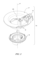
図1は第1実施形態に係る回転コネクタ装置1の斜視図である。図1に示すように、回転コネクタ装置1はステータ10および回転体20を備えている。回転体20はステータ10に対して回転軸線A1回りに回転可能に設けられている。本実施形態では、例えば、ステータ10は車両本体に固定されるように構成されており、回転体20はステアリングホイールに固定されるように構成されている。Hereinafter, embodiments will be described with reference to the drawings. In the figures, the same reference numerals indicate corresponding or identical configurations.
[First embodiment]
FIG. 1 is a perspective view of a
ステータ10は第1ステータ本体11および第2ステータ本体30を含んでいる。第2ステータ本体30は、第1ステータ本体11とは別部材であり、第1ステータ本体11に連結されている。第1ステータ本体11は車両本体に固定されるように構成されている。
図2は回転コネクタ装置1の回転体20の分解斜視図である。図2に示すように、回転体20は、回転プレート21、筒状部22、コネクタ収容部24、およびスリーブ25を含んでいる。回転プレート21は概ね環状の形状を有している。筒状部22は、回転プレート21の内周部から回転軸線A1に沿って延びており、ステアリングシャフトが通る貫通孔22Aを含んでいる。貫通孔22Aは回転軸線A1に沿って延びている。スリーブ25は、環状の形状を有しており、筒状部22に取り付けられている。
FIG. 2 is an exploded perspective view of the
コネクタ収容部24は回転プレート21上に設けられている。例えば、ステアリングホイールに設けられた複数の電気機器(例えば、ホーンスイッチおよびエアバッグユニット)に接続された複数の電気コネクタがコネクタ収容部24に収容されている。
The
図3は回転コネクタ装置1の斜視図である。図3に示すように、回転コネクタ装置1はステータ電気コネクタ40およびハウジングカバー45を備えている。ステータ電気コネクタ40およびハウジングカバー45はステータ10に取り付けられている。ステータ電気コネクタ40は、車両本体に設けられた電気機器(例えば、制御装置およびバッテリー)の電気コネクタに接続されている。
FIG. 3 is a perspective view of the
図4は図1のラインIV-IVにおける回転コネクタ装置1の断面図である。図4に示すように、ステータ10および回転体20は、回転軸線A1を取り囲むように設けられたケーブル収容空間50をステータ10および回転体20の間に画定している。例えば、ケーブル収容空間50は環状である。回転コネクタ装置1は電気ケーブル60を備えている。電気ケーブル60は、ケーブル収容空間50内に配置されており、ステータ電気コネクタ40(図2)に電気的に接続されている。電気ケーブル60は、可撓性を有しており、平坦な形状を有している。電気ケーブル60はフレキシブルフラットケーブルとも呼ばれている。
FIG. 4 is a sectional view of the
図5は回転コネクタ装置1のステータ10の分解斜視図である。図5に示すように、第1ステータ本体11はベースプレート12を含んでいる。ベースプレート12は、開口12Aを含んでおり、環状の形状を有している。第1ステータ本体11はコネクタ収容部13および複数の固定部14を含んでいる。コネクタ収容部13は、ベースプレート12から軸方向D1に沿って延びており、例えば、ヒートステア用の電気コネクタを収容する。複数の固定部14はベースプレート12から径方向外側に突出している。固定部14は、車両本体に固定されるように構成されており、固定孔14Aを有している。第1ステータ本体11は中間壁15を含んでいる。中間壁15は軸方向D1に沿って延びている。具体的には、中間壁15はベースプレート12から軸方向D1に沿って延びている。
FIG. 5 is an exploded perspective view of the
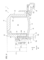
図6は図4のラインVI-VIにおける回転コネクタ装置1の断面図である。図6に示すように、ベースプレート12はケーブル収容空間50を少なくとも部分的に画定している。ベースプレート12は外周部12Bを有している。中間壁15はベースプレート12の外周部12Bから軸方向D1に沿って延びている。
FIG. 6 is a sectional view of the
第2ステータ本体30は第1壁31および第2壁32を含んでいる。第1壁31は、回転軸線A1に平行な軸方向D1に沿って延びており、ケーブル収容空間50を少なくとも部分的に画定している。第2壁32は、軸方向D1に沿って延びており、回転軸線A1に垂直な径方向D2において第1壁31と間隔を空けて配置されている。第1壁31は、径方向D2においてケーブル収容空間50および第2壁32の間に配置されている。第1壁31および第2壁32は、径方向D2においてケーブル収容空間50の外側に配置されている。第2壁32は第1壁31の径方向外側に配置されている。中間壁15は径方向D2において第1壁31および第2壁32の間に配置されている。
The
第2ステータ本体30は径方向D2において第1壁31および第2壁32の間に設けられた中間溝33を含んでいる。中間壁15は中間溝33内に配置されている。第2ステータ本体30は第1壁31を第2壁32に連結する連結部34を含んでいる。中間溝33は、第1壁31、第2壁32、および連結部34により画定されている。第1壁31および第2壁32のうち少なくとも1つは、径方向D2において中間壁15と接触可能である。第1壁31および第2壁32のうち少なくとも1つはベースプレート12と接触可能である。
The
本実施形態では、第1壁31および第2壁32は径方向D2において中間壁15と接触可能である。第1壁31および第2壁32はベースプレート12と接触している。第1壁31、第2壁32、およびベースプレート12により第1ステータ本体11および第2ステータ本体30の軸方向D1の位置決めがなされている。中間壁15は連結部34と軸方向D1に離れている。しかし、第1壁31および第2壁32のうち少なくとも1つが中間壁15と接触していてもよい。第1壁31および第2壁32のうち少なくとも1つがベースプレート12から軸方向D1に離れていてもよい。また、第1壁31および中間壁15の間ならびに第2壁32および中間壁15の間に接着層などの結合構造が設けられていてもよい。
In this embodiment, the
第1壁31は、径方向D2に画定された第1最大厚みT11と、軸方向D1に画定された第1最大長さL11と、を有している。第1最大長さL11は第1最大厚みT11よりも大きい。第2壁32は、径方向D2に画定された第2最大厚みT21と、軸方向D1に画定された第2最大長さL21と、を有している。第2最大長さL21は第2最大厚みT21よりも大きい。中間壁15は、径方向D2に画定された第3最大厚みT31と、軸方向D1に画定された第3最大長さL31と、を有している。第3最大長さL31は第3最大厚みT31よりも大きい。しかし、第1最大長さL11は第1最大厚みT11以下であってもよい。第2最大長さL21は第2最大厚みT21以下であってもよい。第3最大長さL31は第3最大厚みT31以下であってもよい。
The
第1最大長さL11および第2最大長さL12のうち少なくとも1つは、第3最大長さL13よりも長い。第3最大長さL13は、第1最大厚みT11および第2最大厚みT11のうち少なくとも1つよりも長い。本実施形態では、第1最大長さL11および第2最大長さL12は、第3最大長さL13よりも長い。第3最大長さL13は、第1最大厚みT11および第2最大厚みT11よりも長い。しかし、これらの寸法関係は、図6に開示される寸法関係に限定されない。 At least one of the first maximum length L11 and the second maximum length L12 is longer than the third maximum length L13. The third maximum length L13 is longer than at least one of the first maximum thickness T11 and the second maximum thickness T11. In this embodiment, the first maximum length L11 and the second maximum length L12 are longer than the third maximum length L13. The third maximum length L13 is longer than the first maximum thickness T11 and the second maximum thickness T11. However, these dimensional relationships are not limited to those disclosed in FIG.
中間溝33は、軸方向D1に画定された第4最大長さL41を有している。第4最大長さL41は、第3最大長さL31と同じか第3最大長さL31よりも長い。本実施形態では、第4最大長さL41は、第3最大長さL31よりも長い。しかし、第4最大長さL41は、第3最大長さL31と同じであってもよい。
The
中間溝33は、径方向D2に画定された溝幅T41を有している。溝幅T41は、中間壁15の第3最大厚みT31と同じか第3最大厚みT31よりも大きい。本実施形態では、溝幅T41は、中間壁15の第3最大厚みT31よりも大きい。しかし、溝幅T41は、中間壁15の第3最大厚みT31と同じであってもよい。
The
本実施形態では、中間壁15は1個の単一部材としてベースプレート12と一体的に設けられている。しかし、中間壁15はベースプレート12と別部材であってもよい。第1壁31、第2壁32、および連結部34は1個の単一部材として互いに一体的に設けられている。しかし、第1壁31、第2壁32、および連結部34のうち少なくとも1つが他の部分と別部材であってもよい。
In this embodiment, the
図4に示すように、第1壁31、第2壁32、および中間壁15のうち少なくとも1つは、回転軸線A1回りに画定された周方向D3に沿って延びている。第1壁31、第2壁32、および中間壁15のうち少なくとも1つは、周方向D3において90度以上にわたって延びている。第1壁31、第2壁32、および中間壁15のうち少なくとも1つは、周方向D3において180度以上にわたって延びている。本実施形態では、第1壁31、第2壁32、および中間壁15は、周方向D3において90度以上にわたって延びている。第1壁31、第2壁32、および中間壁15は、周方向D3において180度以上にわたって延びている。しかし、第1壁31、第2壁32、および中間壁15のうち少なくとも1つが周方向D3において180度未満の範囲内で延びていてもよい。第1壁31、第2壁32、および中間壁15のうち少なくとも1つが周方向D3において90度未満の範囲内で延びていてもよい。また、第1壁31、第2壁32、および中間壁15のそれぞれは、連続的に周方向D3に沿って延びているが、第1壁31、第2壁32、および中間壁15のうち少なくとも1つが周方向D3に断続的に設けられていてもよい。
As shown in FIG. 4, at least one of the
中間壁15は第1端部15Aおよび第2端部15Bを含んでいる。中間壁15は第1端部15Aから第2端部15Bまで回転軸線A1回りに延びている。第1端部15Aおよび第2端部15Bは回転軸線A1を中心とした周方向範囲R1を画定している。周方向範囲R1は90度以上の中心角を有している。周方向範囲R1は180度以上の中心角を有している。しかし、周方向範囲R1の中心角は本実施形態に限定されない。
実施形態では、中間壁15は湾曲部15C、第1平板部15D、および第2平板部15Eを含んでいる。湾曲部15Cは周方向D3において180度以上にわたって延びている。第1平板部15Dは、湾曲部15Cの端部から直線的に延びており、第1端部15Aを有している。第2平板部15Eは、湾曲部15Cの別の端部から直線的に延びており、第2端部15Bを有している。回転軸線A1に沿った方向から見た場合に、中間溝33は中間壁15と相補的な形状を有している。
In the embodiment, the
湾曲部15Cは回転軸線A1を中心とした周方向範囲R2を画定している。湾曲部15Cは周方向範囲R2において回転軸線A1を中心に円弧状に延びている。周方向範囲R2は90度以上の中心角を有している。周方向範囲R2は180度以上の中心角を有している。しかし、周方向範囲R2の中心角は本実施形態に限定されない。 The curved portion 15C defines a circumferential range R2 centered on the rotation axis A1. The curved portion 15C extends in an arc shape around the rotation axis A1 in the circumferential range R2. The circumferential range R2 has a central angle of 90 degrees or more. The circumferential range R2 has a central angle of 180 degrees or more. However, the central angle of the circumferential range R2 is not limited to this embodiment.
第1壁31は第1端部31Aおよび第2端部31Bを含んでいる。第1壁31は第1端部31Aから第2端部31Bまで回転軸線A1回りに延びている。実施形態では、第1壁31は湾曲部31C、第1平板部31D、および第2平板部31Eを含んでいる。湾曲部31Cは周方向D3において180度以上にわたって延びている。第1平板部31Dは、湾曲部31Cの端部から直線的に延びており、第1端部31Aを有している。第2平板部31Eは、湾曲部31Cの別の端部から直線的に延びており、第2端部31Bを有している。中間壁15の湾曲部15Cと同様に、湾曲部31Cは周方向範囲R2において回転軸線A1を中心に円弧状に延びている。
The
第2壁32は第1端部32Aおよび第2端部32Bを含んでいる。第2壁32は第1端部32Aから第2端部32Bまで回転軸線A1回りに延びている。本実施形態では、第2壁32は湾曲部32C、第1平板部32D、および第2平板部32Eを含んでいる。湾曲部32Cは周方向D3において180度以上にわたって延びている。第1平板部32Dは、湾曲部32Cの端部から直線的に延びており、第1端部32Aを有している。第2平板部32Eは、湾曲部32Cの別の端部から直線的に延びており、第2端部32Bを有している。中間壁15の湾曲部15Cと同様に、湾曲部32Cは周方向範囲R2において回転軸線A1を中心に円弧状に延びている。
The
第2ステータ本体30は第3壁35を含んでいる。第3壁35は第1壁31から周方向D3に沿って延びている。より詳細には、第3壁35は第1平板部31Dから第2平板部31Eの方に周方向D3に沿って延びている。第3壁35は第2平板部31Eと間隔を空けて配置されている。第3壁35はケーブル収容空間50を部分的に画定している。
The
第2ステータ本体30はケーブル通路36を含んでいる。ケーブル通路36はケーブル収容空間50に接続されている。電気ケーブル60はケーブル通路36を通ってケーブル収容空間50からケーブル収容空間50の外側に引き出されている。ケーブル通路36は第1通路36Aおよび第2通路36Bを含んでいる。第1通路36Aはケーブル収容空間50から第1壁31の第2平板部31Eに沿って延びている。第2通路36Bは第1通路36Aからケーブル収容空間50の外周に沿って第1壁31の第1平板部31Dの方に延びている。ケーブル通路36は中間壁15の第1平板部15Dおよび第2平板部15Eの間に配置されている。
図4における上下方向は、ステータ10を車両本体に搭載した場合のステータ10の上下方向と概ね一致している。ステータ10を車両本体に搭載した場合に、中間壁15の少なくとも一部は、回転軸線A1よりも上側に配置されている。本実施形態では、ステータ10を車両本体に搭載した場合に、中間壁15の一部はステータ10における最上部に配置されている。ステータ10を車両本体に搭載した場合に、中間壁15は、回転軸線A1よりも上側の領域全体にわたって配置されている。
The vertical direction in FIG. 4 generally corresponds to the vertical direction of the
図5に示すように、第2ステータ本体30はカバー部37を含んでいる。第2ステータ本体30が第1ステータ本体11に連結されている状態で、カバー部37はコネクタ収容部13を部分的に覆っている。図4に示すように、カバー部37は第1壁31の第1端部31Aおよび第2壁32の第1端部32Aから第1壁31の第2端部31Bおよび第2壁32の第2端部32Bまで周方向D3に沿って延びている。カバー部37は第1壁31の第1端部31Aおよび第2壁32の第1端部32Aを第1壁31の第2端部31Bおよび第2壁32の第2端部32Bに連結している。カバー部37は第3壁35と連結されている。ケーブル通路36は第1壁31、第3壁35、およびカバー部37の間に画定されている。
As shown in FIG. 5, the second stator
図5に示すように、第1ステータ本体11は連結体16Aを含んでいる。連結体16Aはベースプレート12から軸方向D1に沿って延びている。連結体16Aは第2ステータ本体30を第1ステータ本体11に連結する。本実施形態では、第1ステータ本体11は複数の連結体16Aを含んでいる。複数の連結体16Aは周方向D3に間隔を空けて配置されている。複数の連結体16Aは軸方向D1において概ね同じ位置に配置されている。複数の連結体16Aは中間壁15の径方向外側に配置されている。しかし、連結体16Aの総数および配置は本実施形態に限定されない。複数の連結体16Aのうち少なくとも1つが第1ステータ本体11から省略されていてもよい。
As shown in FIG. 5, the first stator
第1ステータ本体11は追加連結体16Bを含んでいる。追加連結体16Bは連結体16Aから軸方向D1にずれた位置に配置されている。追加連結体16Bは中間壁15の第1端部15Aおよび第2端部15Bの間であって第1端部15Aおよび第2端部15Bから軸方向D1にずれた位置に配置されている。本実施形態では、第1ステータ本体11は複数の追加連結体16Bを含んでいる。しかし、追加連結体16Bの総数は本実施形態に限定されない。複数の追加連結体16Bのうち少なくとも1つが第1ステータ本体11から省略されてもよい。
The
図7は回転コネクタ装置1の部分斜視図である。図7に示すように、連結体16Aは連結溝16Cを含んでいる。連結溝16Cは軸方向D1に沿って延びている。しかし、連結体16Aの形状は本実施形態に限定されない。
FIG. 7 is a partial perspective view of the
図8は図4のラインVIII-VIIIにおける回転コネクタ装置1の断面図である。図8に示すように、連結体16Aは径方向D2において中間壁15と間隔を空けて配置されている。第2壁32は径方向D2において中間壁15および連結体16Aの間に配置されている。第2ステータ本体30は突起38Aを含んでいる。突起38Aは第2壁32から径方向外側に突出している。連結体16Aは第2ステータ本体30を第1ステータ本体11に連結するように突起38Aに接触可能である。本実施形態では、第2ステータ本体30が第1ステータ本体11に連結されている状態で、突起38Aは連結溝16C内に配置されている。
FIG. 8 is a sectional view of the
図4に示すように、本実施形態では、第2ステータ本体30は複数の突起38Aを含んでいる。突起38Aの総数は連結体16Aの総数と同じである。しかし、突起38Aの総数は本実施形態に限定されない。
As shown in FIG. 4, in this embodiment, the second stator
図9は回転コネクタ装置1の部分斜視図である。図9に示すように、追加連結体16Bは追加連結溝16Dを含んでいる。追加連結溝16Dは軸方向D1に沿って延びている。しかし、追加連結体16Bの形状は本実施形態に限定されない。
FIG. 9 is a partial perspective view of the
図10は図4のラインX-Xにおける回転コネクタ装置1の断面図である。図10に示すように、第2ステータ本体30は追加突起38Bを含んでいる。追加突起38Bは径方向D2においてカバー部37から外側に突出している。追加連結体16Bは第2ステータ本体30を第1ステータ本体11に連結するように追加突起38Bに接触可能である。本実施形態では、第2ステータ本体30が第1ステータ本体11に連結されている状態で、追加突起38Bは追加連結溝16D内に配置されている。
FIG. 10 is a sectional view of the
図9に示すように、本実施形態では、第2ステータ本体30は複数の追加突起38Bを含んでいる。しかし、追加突起38Bの総数は本実施形態に限定されない。複数の追加突起38Bのうち少なくとも1つが第2ステータ本体30から省略されてもよい。
As shown in FIG. 9, in this embodiment, the second stator
図11は回転コネクタ装置1の部分断面図である。図12はステータ10の第2ステータ本体30の部分斜視図である。図11に示すように、第2壁32は外周面32Fおよび外側凹部32Gを含んでいる。外側凹部32Gは外周面32Fに設けられている。連結体16Aは外側凹部32G内に配置されている。突起38Aは外側凹部32G内に配置されている。図12に示すように、外側凹部32Gは軸方向D1に沿って延びている。
FIG. 11 is a partial cross-sectional view of the
図4に示すように、本実施形態では、第2壁32は複数の外側凹部32Gを含んでいる。複数の連結体16Aは複数の外側凹部32G内にそれぞれ配置されている。しかし、外側凹部32Gの総数は本実施形態に限定されない。複数の外側凹部32Gのうち少なくとも1つが第2壁32から省略されていてもよい。
As shown in FIG. 4, in this embodiment, the
図13はステータ10の第1ステータ本体11の部分斜視図である。図13に示すように、中間壁15は中間外周面15Fおよび中間凹部15Gを含んでいる。中間凹部15Gは中間外周面15Fに設けられている。中間凹部15Gはベースプレート12から軸方向D1に沿って延びている。
FIG. 13 is a partial perspective view of the first stator
図11に示すように、第2壁32は中間凹部15G内に配置された突出部32Hを含んでいる。第2壁32は内周面32Kを含んでいる。突出部32Hは内周面32Kから径方向内側に突出している。第2壁32の内周面32Kは中間外周面15Fと向かい合っている。
As shown in FIG. 11, the
中間凹部15Gは外側凹部32Gの径方向内側に配置されている。軸方向D1から見た場合に、周方向D3において、中間凹部15Gの位置は、外側凹部32Gの位置と概ね同じである。外側凹部32Gは周方向D3に画定された第1周方向長さCL1を有している。中間凹部15Gは周方向D3に画定された第2周方向長さCL2を有している。連結体16Aは周方向D3に画定された第3周方向長さCL3を有している。突出部32Hは周方向D3に画定された第4周方向長さCL4を有している。第2周方向長さCL2は第1周方向長さCL1、第3周方向長さCL3、および第4周方向長さCL4よりも長い。第4周方向長さCL4は第1周方向長さCL1および第3周方向長さCL3よりも長い。第1周方向長さCL1は第3周方向長さCL3よりも長い。第1~第4周方向長さCL1~CL4の寸法関係は本実施形態に限定されない。中間凹部15Gと外側凹部32Gとの位置関係は本実施形態に限定されない。
The
図4に示すように、本実施形態では、中間壁15は複数の中間凹部15Gを含んでいる。第2壁32は複数の突出部32Hを含んでいる。複数の突出部32Hは複数の中間凹部15G内にそれぞれ配置されている。中間凹部15Gの総数は連結体16Aの総数と同じである。しかし、中間凹部15Gおよび突出部32Hの総数は本実施形態に限定されない。
As shown in FIG. 4, in this embodiment, the
図8に示すように、中間壁15は径方向D2に画定された厚みT22を有している。厚みT22は中間凹部15Gの範囲内に画定されている。厚みT22は第2最大厚みT21(図6)よりも小さい。第2壁32は径方向D2に画定された厚みT32を有している。厚みT32は外側凹部32Gの範囲内において画定されている。厚みT32は第3最大厚みT31(図6)よりも小さい。厚みT32は厚みT22よりも小さい。しかし、厚みT22およびT32の寸法関係は本実施形態に限定されない。
As shown in FIG. 8, the
図10に示すように、第1ステータ本体11は中間壁17を含んでいる。本実施形態では、コネクタ収容部13が中間壁17を含んでいる。中間壁17は軸方向D1に沿って延びている。第2ステータ本体30は第1壁71および第2壁72を含んでいる。本実施形態では、カバー部37が第1壁71および第2壁72を含んでいる。第1壁71は、軸方向D1に沿って延びており、コネクタ収容空間80を少なくとも部分的に画定している。コネクタ収容空間80はケーブル通路36に接続されている。第2壁72は、軸方向D1に沿って延びており、径方向D2において第1壁71と間隔を空けて配置されている。第2壁72は第1壁71の径方向外側に配置されている。中間壁17は径方向D2において第1壁71および第2壁72の間に配置されている。
As shown in FIG. 10, the
第2ステータ本体30は径方向D2において第1壁71および第2壁72の間に設けられた中間溝73を含んでいる。中間壁17は中間溝73内に配置されている。第2ステータ本体30は第1壁71を第2壁72に連結する連結部74を含んでいる。中間溝73は、第1壁71、第2壁72、および連結部74により画定されている。第1壁71および第2壁72のうち少なくとも1つは、径方向D2において中間壁17と接触可能である。本実施形態では、第1壁71および第2壁72は径方向D2において中間壁17と接触可能である。第1壁71および中間壁17の間ならびに第2壁72および中間壁17の間に接着層などの結合構造が設けられていてもよい。追加連結体16Bは中間壁17に連結されている。追加突起38Bは第2壁72から径方向外側に突出している。
The
中間壁17、第1壁71、および第2壁72は、中間壁15、第1壁31、および第2壁32と概ね同じ構造を有している。したがって、中間壁17、第1壁71、および第2壁72の詳細な説明は省略する。
The
回転コネクタ装置1の特徴は以下の通りである。
(1)図6に示すように、回転コネクタ装置1では、第1ステータ本体11の中間壁15が径方向D2において第1壁31および第2壁32の間に配置されているので、ステータ10の外側からケーブル収容空間50までの経路が長くなる。したがって、ステータ10の外側からケーブル収容空間50に異物が侵入しにくくなり、回転コネクタ装置1の耐環境性を高めることができる。
(2)図6に示すように、第1壁31がケーブル収容空間50を少なくとも部分的に画定しているので、回転コネクタ装置1の大型化を抑制しつつ回転コネクタ装置1の耐環境性を高めることができる。
(3)図6に示すように、第1壁31および第2壁32が径方向D2においてケーブル収容空間50の外側に配置されているので、外部に露出しやすい回転コネクタ装置1の外周部の耐環境性を高めることができる。
(4)図6に示すように、第1最大長さL11が第1最大厚みT11よりも大きいので、ステータ10の外側からケーブル収容空間50までの経路をさらに長くできる。
(5)図6に示すように、第2最大長さL21が第2最大厚みT21よりも大きいので、ステータ10の外側からケーブル収容空間50までの経路をさらに長くできる。
(6)図6に示すように、第3最大長さL31が第3最大厚みT31よりも大きいので、ステータ10の外側からケーブル収容空間50までの経路をさらに長くできる。
(7)図6に示すように、中間壁15が中間溝33内に配置されているので、ステータ10の外側からケーブル収容空間50までの経路にラビリンス構造を形成することができる。
(8)図6に示すように、中間溝33が第1壁31、第2壁32、および連結部34により画定されているので、ステータ10の外側からケーブル収容空間50までの経路にラビリンス構造を確実に形成することができる。
(9)図6に示すように、第1壁31および第2壁32のうち少なくとも1つが径方向D2において中間壁15と接触可能である。したがって、ステータ10の外側からケーブル収容空間50までの経路を狭くすることができ、回転コネクタ装置1の耐環境性をさらに高めることができる。
(10)図4に示すように、第1壁31、第2壁32、および中間壁15のうち少なくとも1つが回転軸線A1回りに画定された周方向D3に沿って延びているので、ステータ10の外側からケーブル収容空間50までの経路が長くなる範囲を周方向D3に広く確保できる。これにより、回転コネクタ装置1の耐環境性をさらに高めることができる。
(11)図4に示すように、第1壁31、第2壁32、および中間壁15のうち少なくとも1つが周方向D3において90度以上にわたって延びているので、ステータ10の外側からケーブル収容空間50までの経路が長くなる範囲を周方向D3に確実に広く確保できる。
(12)図4に示すように、第1壁31、第2壁32、および中間壁15のうち少なくとも1つが周方向D3において180度以上にわたって延びているので、ステータ10の外側からケーブル収容空間50までの経路が長くなる範囲を周方向D3により確実に広く確保できる。
(13)図8に示すように、第2壁32が径方向D2において中間壁15および連結体16Aの間に配置されているので、第2壁32の外側からケーブル収容空間50までの経路を長くしつつ、連結体16Aの連結強度を高めることができる。
(14)図8に示すように、第2ステータ本体30を第1ステータ本体11に連結するように連結体16Aが突起38Aに接触可能であるので、第2ステータ本体30および第1ステータ本体11の連結強度をさらに高めることができる。
(15)図11に示すように、連結体16Aが外側凹部32G内に配置されているので、ステータ10の大型化を抑制しつつ第1ステータ本体11および第2ステータ本体30の連結強度を高めることができる。
(16)図11に示すように、中間凹部15Gが外側凹部32Gの径方向内側に配置されているので、ステータ10の大型化を抑制しつつ、ステータ10の外側からケーブル収容空間50までの経路を長くできる。
(17)図11に示すように、第2壁32が中間凹部15G内に配置された突出部32Hを含んでいるので、第1ステータ本体11および第2ステータ本体30の周方向D3の位置決めが容易となる。
(18)図6に示すように、中間壁15がベースプレート12の外周部12Bから軸方向D1に沿って延びているので、ケーブル収容空間50を広く確保しつつ、ステータ10の外側からケーブル収容空間50までの経路を長くできる。
(19)図4に示すように、ステータ10を車両本体に搭載した場合に、中間壁15の少なくとも一部は、回転軸線A1よりも上側に配置されるので、ステータ10を車両本体に搭載した状態で、例えば液体が回転コネクタ装置1にこぼれても、中間壁15により液体のケーブル収容空間50への侵入を確実に抑制できる。
(20)図6に示すように、第1最大長さL11および第2最大長さL21のうち少なくとも1つは、第3最大長さL31よりも長いので、第1壁31および第2壁32のうち少なくとも1つと中間壁15との間の隙間の長さをより長く確保できる。
(21)図6に示すように、第4最大長さL41は、第3最大長さL31と同じか第3最大長さL31よりも長いので、中間溝33の長さをより長く確保できる。
〔第2実施形態〕
次に、図14および図15を参照して、第2実施形態に係る回転コネクタ装置201を説明する。回転コネクタ装置201は、第1ステータ本体および第2ステータ本体以外は回転コネクタ装置201と同じ構造を有する。したがって、本明細書では、説明を簡潔にするために、第1実施形態で説明した機能と実質的に同じ機能を有する要素は同じ番号で示し、それらの説明は省略する。The features of the
(1) As shown in FIG. 6, in the
(2) As shown in FIG. 6, since the
(3) As shown in FIG. 6, the
(4) As shown in FIG. 6, since the first maximum length L11 is larger than the first maximum thickness T11, the path from the outside of the
(5) As shown in FIG. 6, since the second maximum length L21 is larger than the second maximum thickness T21, the path from the outside of the
(6) As shown in FIG. 6, since the third maximum length L31 is larger than the third maximum thickness T31, the path from the outside of the
(7) As shown in FIG. 6, since the
(8) As shown in FIG. 6, since the
(9) As shown in FIG. 6, at least one of the
(10) As shown in FIG. 4, at least one of the
(11) As shown in FIG. 4, at least one of the
(12) As shown in FIG. 4, at least one of the
(13) As shown in FIG. 8, since the
(14) As shown in FIG. 8, since the connecting
(15) As shown in FIG. 11, since the connecting
(16) As shown in FIG. 11, since the
(17) As shown in FIG. 11, since the
(18) As shown in FIG. 6, since the
(19) As shown in FIG. 4, when the
(20) As shown in FIG. 6, at least one of the first maximum length L11 and the second maximum length L21 is longer than the third maximum length L31, so the
(21) As shown in FIG. 6, the fourth maximum length L41 is the same as or longer than the third maximum length L31, so the length of the
[Second embodiment]
Next, a
図14は、第2実施形態に係る回転コネクタ装置201の部分断面図であり、第1実施形態の図6に対応している。図15は、回転コネクタ装置201の別の部分断面図であり、第1実施形態の図8に対応している。
FIG. 14 is a partial sectional view of the
図14および図15に示すように、回転コネクタ装置201はステータ210および回転体20を備えている。ステータ210は第1ステータ本体211および第2ステータ本体230を含んでいる。第2ステータ本体230は、第1ステータ本体211とは別部材であり、第1ステータ本体211に連結されている。ステータ210は第1実施形態のステータ10と概ね同じ構造を有している。本実施形態では、第1ステータ本体211および第2ステータ本体230の位置関係が第1実施形態の第1ステータ本体11および第2ステータ本体30の位置関係と入れ替わっている。
As shown in FIGS. 14 and 15, the
具体的には、第1ステータ本体211は中間壁15を含んでいる。第2ステータ本体230は第1壁31および第2壁32を含んでいる。第1実施形態とは異なり、本実施形態では、第2ステータ本体230がベースプレート12を含んでいる。第1壁31および第2壁32はベースプレート12の外周部12Bから軸方向D1に沿って延びている。
Specifically,
本実施形態では、第1壁31および第2壁32は1個の単一部材としてベースプレート12と一体的に設けられている。しかし、第1壁31および第2壁32のうち少なくとも1つはベースプレート12と別部材であってもよい。
In this embodiment, the
回転コネクタ装置201では、第1実施形態の回転コネクタ装置1と概ね同じ効果を得ることができる。
With the
なお、本願においては、「備えている」およびその派生語は、構成要素の存在を説明する非制限用語であり、記載されていない他の構成要素の存在を排除しない。これは、「有している」、「含んでいる」およびそれらの派生語にも適用される。 In this application, "comprises" and its derivatives are non-limiting terms that describe the presence of a component, and do not exclude the presence of other components that are not described. This also applies to "having," "including," and their derivatives.
本願において、「第1」や「第2」などの序数は、単に構成を識別するための用語であって、他の意味(例えば特定の順序など)は有していない。例えば、「第1要素」があるからといって「第2要素」が存在していることを暗に意味しているわけではなく、また「第2要素」があるからといって「第1要素」が存在していることを暗に意味しているわけではない。 In this application, ordinal numbers such as "first" and "second" are simply terms for identifying configurations and do not have any other meaning (eg, specific order, etc.). For example, the presence of a "first element" does not imply the existence of a "second element," and the presence of a "second element" does not imply the existence of a "first element." It does not imply that "element" is present.
また、本開示における「平行」「直交」および「一致」の表現は、厳密に解釈されるべきではなく、「実質的な平行」「実質的な直交」および「実質的な一致」の意味をそれぞれ含む。また、その他の配置に関する表現も、厳密に解釈されるものではない。 In addition, the expressions "parallel," "orthogonal," and "corresponding" in this disclosure should not be interpreted strictly, but should be interpreted as "substantially parallel," "substantially orthogonal," and "substantially coincident." Includes each. Furthermore, expressions regarding other arrangements are not to be strictly interpreted.
また、本開示における「AおよびBのうち少なくとも1つ」という表現は、例えば、(1)Aのみ、(2)Bのみ、および(3)AおよびBの両方、のいずれも包含している。「A、BおよびCのうち少なくとも1つ」という表現は、例えば、(1)Aのみ、(2)Bのみ、(3)Cのみ、(4)AおよびB、(5)BおよびC、(6)AおよびC、(7)A、BおよびCの全て、のいずれも包含している。本開示では、「AおよびBのうち少なくとも1つ」という表現は、「Aのうち少なくとも1つおよびBのうち少なくとも1つ」とは解釈されない。 Furthermore, the expression "at least one of A and B" in the present disclosure includes, for example, (1) only A, (2) only B, and (3) both A and B. . The expression "at least one of A, B, and C" includes, for example, (1) only A, (2) only B, (3) only C, (4) A and B, (5) B and C, (6) A and C, and (7) all of A, B and C are included. In this disclosure, the expression "at least one of A and B" is not interpreted as "at least one of A and at least one of B."
上記の開示内容から考えて、本発明の種々の変更や修正が可能であることは明らかである。したがって、本発明の趣旨を逸脱しない範囲で、本願の具体的な開示内容とは別の方法で本発明が実施されてもよい。 Obviously, various changes and modifications of the present invention are possible in light of the above disclosure. Therefore, the present invention may be implemented in a manner other than the specific disclosure of the present application without departing from the spirit of the present invention.
1、201 回転コネクタ装置
10、210 ステータ
11、211 第1ステータ本体
12 ベースプレート
12B 外周部
15 中間壁
15F 中間外周面
15G 中間凹部
16A 連結体
20 回転体
30、230 第2ステータ本体
31 第1壁
32 第2壁
32F 外周面
32G 外側凹部
32H 突出部
33 中間溝
34 連結部
38A 突起
50 ケーブル収容空間
A1 回転軸線
D1 軸方向
D2 径方向
D3 周方向
T11 第1最大厚み
T21 第2最大厚み
T31 第3最大厚み
L11 第1最大長さ
L21 第2最大長さ
L31 第3最大長さ
L41 第4最大長さ1, 201
Claims (20)
前記ステータに対して回転軸線回りに回転可能に設けられた回転体と、を備え、
前記ステータおよび前記回転体は、前記回転軸線を取り囲むように設けられたケーブル収容空間を前記ステータおよび前記回転体の間に画定し、
前記第2ステータ本体は、前記回転軸線に平行な軸方向に沿って延びた第1壁と、前記軸方向に沿って延び前記回転軸線に垂直な径方向において前記第1壁と間隔を空けて配置された第2壁と、を含み、
前記第1壁は、前記径方向において前記ケーブル収容空間および前記第2壁の間に配置され、
前記第1ステータ本体は、前記軸方向に沿って延び前記径方向において前記第1壁および前記第2壁の間に配置された中間壁を含み、
前記中間壁は、中間外周面と、前記中間外周面に設けられた中間凹部と、を含み、
前記第2壁は、内周面と、前記内周面から径方向内側に突出し前記中間凹部内に配置された突出部と、を含む、
回転コネクタ装置。 a stator including a first stator main body; and a second stator main body that is a separate member from the first stator main body and connected to the first stator main body;
a rotating body rotatably provided around a rotational axis with respect to the stator;
The stator and the rotating body define a cable accommodation space between the stator and the rotating body, which is provided so as to surround the rotational axis;
The second stator body includes a first wall extending along an axial direction parallel to the rotational axis, and a spaced apart from the first wall in a radial direction extending along the axial direction and perpendicular to the rotational axis. a second wall arranged;
the first wall is arranged between the cable accommodation space and the second wall in the radial direction,
The first stator body includes an intermediate wall extending along the axial direction and disposed between the first wall and the second wall in the radial direction,
The intermediate wall includes an intermediate outer circumferential surface and an intermediate recess provided in the intermediate outer circumferential surface,
The second wall includes an inner circumferential surface and a protrusion that protrudes radially inward from the inner circumferential surface and is disposed within the intermediate recess.
Rotary connector device.
請求項1に記載の回転コネクタ装置。 the first wall at least partially defines the cable accommodation space;
A rotary connector device according to claim 1.
請求項1または2に記載の回転コネクタ装置。 the first wall and the second wall are arranged outside the cable accommodation space in the radial direction;
The rotary connector device according to claim 1 or 2.
前記第1最大長さは、前記第1最大厚みよりも大きい、
請求項1~3のいずれか1項に記載の回転コネクタ装置。 the first wall has a first maximum thickness defined in the radial direction and a first maximum length defined in the axial direction;
the first maximum length is greater than the first maximum thickness;
The rotary connector device according to any one of claims 1 to 3.
前記第2最大長さは、前記第2最大厚みよりも大きい、
請求項1~4のいずれか1項に記載の回転コネクタ装置。 the second wall has a second maximum thickness defined in the radial direction and a second maximum length defined in the axial direction;
the second maximum length is greater than the second maximum thickness;
The rotary connector device according to any one of claims 1 to 4.
前記第3最大長さは、前記第3最大厚みよりも大きい、
請求項1~5のいずれか1項に記載の回転コネクタ装置。 The intermediate wall has a third maximum thickness defined in the radial direction and a third maximum length defined in the axial direction,
the third maximum length is greater than the third maximum thickness;
The rotary connector device according to any one of claims 1 to 5.
前記中間壁は、前記中間溝内に配置される、
請求項1~6のいずれか1項に記載の回転コネクタ装置。 The second stator body includes an intermediate groove provided between the first wall and the second wall in the radial direction,
the intermediate wall is disposed within the intermediate groove;
A rotary connector device according to any one of claims 1 to 6.
前記中間溝は、前記第1壁、前記第2壁、および前記連結部により画定される、
請求項7に記載の回転コネクタ装置。 The second stator body includes a connecting portion connecting the first wall to the second wall,
The intermediate groove is defined by the first wall, the second wall, and the connecting portion,
A rotary connector device according to claim 7.
請求項1~8のいずれか1項に記載の回転コネクタ装置。 At least one of the first wall and the second wall is capable of contacting the intermediate wall in the radial direction.
A rotary connector device according to any one of claims 1 to 8.
請求項1~9のいずれか1項に記載の回転コネクタ装置。 At least one of the first wall, the second wall, and the intermediate wall extends in a circumferential direction defined around the rotation axis.
A rotary connector device according to any one of claims 1 to 9.
請求項10に記載の回転コネクタ装置。 At least one of the first wall, the second wall, and the intermediate wall extends over 90 degrees in the circumferential direction.
A rotary connector device according to claim 10.
請求項11に記載の回転コネクタ装置。 At least one of the first wall, the second wall, and the intermediate wall extends over 180 degrees or more in the circumferential direction.
A rotary connector device according to claim 11.
前記第2壁は、前記径方向において前記中間壁および前記連結体の間に配置される、
請求項1~12のいずれかに記載の回転コネクタ装置。 The first stator body includes a base plate that at least partially defines the cable accommodation space, and a connecting body extending from the base plate along the axial direction and spaced from the intermediate wall in the radial direction. including;
the second wall is arranged between the intermediate wall and the connecting body in the radial direction;
A rotary connector device according to any one of claims 1 to 12.
前記連結体は、前記第2ステータ本体を前記第1ステータ本体に連結するように前記突起に接触可能である、
請求項13に記載の回転コネクタ装置。 The second stator body includes a protrusion that protrudes radially outward from the second wall,
the connecting body is capable of contacting the protrusion to connect the second stator body to the first stator body;
A rotary connector device according to claim 13.
前記連結体は、前記外側凹部内に配置される、
請求項13または14に記載の回転コネクタ装置。 The second wall includes an outer peripheral surface and an outer recess provided in the outer peripheral surface,
the connecting body is disposed within the outer recess;
Rotary connector device according to claim 13 or 14.
請求項15に記載の回転コネクタ装置。 the intermediate recess is arranged radially inward of the outer recess;
A rotary connector device according to claim 15.
前記中間壁は、前記ベースプレートの前記外周部から前記軸方向に沿って延びる、
請求項1~12のいずれか1項に記載の回転コネクタ装置。 The first stator body includes a base plate having an outer circumference and at least partially defining the cable accommodation space,
The intermediate wall extends along the axial direction from the outer peripheral portion of the base plate.
A rotary connector device according to any one of claims 1 to 12.
請求項1~17のいずれか1項に記載の回転コネクタ装置。 When the stator is mounted on a vehicle body, at least a portion of the intermediate wall is located above the rotation axis.
A rotary connector device according to any one of claims 1 to 17 .
前記第2壁は、前記軸方向に画定された第2最大長さを有し、
前記中間壁は、前記軸方向に画定された第3最大長さを有し、
前記第1最大長さおよび前記第2最大長さのうち少なくとも1つは、前記第3最大長さよりも長い、
請求項1~18のいずれか1項に記載の回転コネクタ装置。 the first wall has a first maximum length defined in the axial direction;
the second wall has a second maximum length defined in the axial direction;
the intermediate wall has a third maximum length defined in the axial direction;
at least one of the first maximum length and the second maximum length is longer than the third maximum length;
A rotary connector device according to any one of claims 1 to 18 .
前記中間壁は、前記軸方向に画定された第3最大長さを有し、
前記中間溝は、前記軸方向に画定された第4最大長さを有し、
前記第4最大長さは、前記第3最大長さと同じか前記第3最大長さよりも長い、
請求項1~19のいずれか1項に記載の回転コネクタ装置。 The second stator body includes an intermediate groove provided between the first wall and the second wall in the radial direction,
the intermediate wall has a third maximum length defined in the axial direction;
the intermediate groove has a fourth maximum length defined in the axial direction;
The fourth maximum length is the same as or longer than the third maximum length,
A rotary connector device according to any one of claims 1 to 19 .
Applications Claiming Priority (3)
| Application Number | Priority Date | Filing Date | Title |
|---|---|---|---|
| JP2018233783 | 2018-12-13 | ||
| JP2018233783 | 2018-12-13 | ||
| PCT/JP2019/045104 WO2020121741A1 (en) | 2018-12-13 | 2019-11-18 | Rotary connector device |
Publications (2)
| Publication Number | Publication Date |
|---|---|
| JPWO2020121741A1 JPWO2020121741A1 (en) | 2021-10-28 |
| JP7371010B2 true JP7371010B2 (en) | 2023-10-30 |
Family
ID=71076304
Family Applications (1)
| Application Number | Title | Priority Date | Filing Date |
|---|---|---|---|
| JP2020559876A Active JP7371010B2 (en) | 2018-12-13 | 2019-11-18 | rotating connector device |
Country Status (6)
| Country | Link |
|---|---|
| US (1) | US11901683B2 (en) |
| EP (1) | EP3896803A4 (en) |
| JP (1) | JP7371010B2 (en) |
| KR (1) | KR20210098529A (en) |
| CN (1) | CN113261164B (en) |
| WO (1) | WO2020121741A1 (en) |
Citations (5)
| Publication number | Priority date | Publication date | Assignee | Title |
|---|---|---|---|---|
| JP3408922B2 (en) | 1996-05-24 | 2003-05-19 | アルプス電気株式会社 | Rotating connector |
| JP2007012521A (en) | 2005-07-01 | 2007-01-18 | Yazaki Corp | Rotating connector device |
| JP2013020850A (en) | 2011-07-12 | 2013-01-31 | Niles Co Ltd | Rotary connector device |
| JP2013157209A (en) | 2012-01-30 | 2013-08-15 | Niles Co Ltd | Rotary connector device |
| WO2017170752A1 (en) | 2016-03-31 | 2017-10-05 | 古河電気工業株式会社 | Rotary connector device |
Family Cites Families (21)
| Publication number | Priority date | Publication date | Assignee | Title |
|---|---|---|---|---|
| US5674082A (en) * | 1995-02-21 | 1997-10-07 | Niles Parts Co., Ltd. | Rotary connector device |
| JP4234446B2 (en) | 2003-01-10 | 2009-03-04 | 古河電気工業株式会社 | Rotating connector device |
| US7104821B2 (en) * | 2004-09-16 | 2006-09-12 | Alps Electric Co., Ltd. | Rotary connector |
| JP2008007075A (en) * | 2006-06-30 | 2008-01-17 | Yazaki Corp | Steering angle sensor built-in type rotary connector device |
| JP5097364B2 (en) * | 2006-06-30 | 2012-12-12 | 矢崎総業株式会社 | Rotation connector device with built-in rudder angle sensor |
| JP2008021555A (en) * | 2006-07-13 | 2008-01-31 | Alps Electric Co Ltd | Rotating connector |
| JP5259265B2 (en) * | 2008-06-19 | 2013-08-07 | ナイルス株式会社 | Rotating connector device |
| JP5241016B2 (en) * | 2009-01-29 | 2013-07-17 | 矢崎総業株式会社 | Rotating connector |
| JP5224404B2 (en) * | 2010-03-30 | 2013-07-03 | 古河電気工業株式会社 | Rotating connector device |
| JP5117528B2 (en) * | 2010-03-30 | 2013-01-16 | 古河電気工業株式会社 | Rotating connector device |
| JP5117529B2 (en) * | 2010-03-30 | 2013-01-16 | 古河電気工業株式会社 | Rotating connector device |
| EP2597734B1 (en) * | 2010-09-27 | 2017-04-12 | The Furukawa Electric Co., Ltd. | Rotary connector device |
| JP4974195B2 (en) * | 2010-10-20 | 2012-07-11 | 古河電気工業株式会社 | Rotating connector device |
| JP5184716B2 (en) * | 2010-11-19 | 2013-04-17 | 古河電気工業株式会社 | Rotating connector device |
| EP2685571B1 (en) * | 2011-03-09 | 2017-05-03 | Furukawa Electric Co., Ltd. | Rotatable connector device |
| JP4974196B1 (en) * | 2011-09-29 | 2012-07-11 | 古河電気工業株式会社 | Rotating connector device |
| JP5886148B2 (en) * | 2012-06-21 | 2016-03-16 | 株式会社ヴァレオジャパン | Rotating connector device |
| CN104067461B (en) * | 2013-01-15 | 2016-06-22 | 古河电气工业株式会社 | It is built-in with the rotary connector of sensor |
| JP6754377B2 (en) * | 2016-01-08 | 2020-09-09 | 古河電気工業株式会社 | Rotating connector device |
| CN109075515B (en) * | 2016-03-31 | 2020-11-03 | 古河电气工业株式会社 | Rotary connector device |
| US10981525B2 (en) * | 2017-02-10 | 2021-04-20 | Furukawa Electric Co., Ltd. | Rotary connector device |
-
2019
- 2019-11-18 CN CN201980079448.8A patent/CN113261164B/en active Active
- 2019-11-18 EP EP19896917.2A patent/EP3896803A4/en active Pending
- 2019-11-18 WO PCT/JP2019/045104 patent/WO2020121741A1/en unknown
- 2019-11-18 JP JP2020559876A patent/JP7371010B2/en active Active
- 2019-11-18 KR KR1020217021151A patent/KR20210098529A/en not_active Application Discontinuation
-
2021
- 2021-05-26 US US17/330,413 patent/US11901683B2/en active Active
Patent Citations (5)
| Publication number | Priority date | Publication date | Assignee | Title |
|---|---|---|---|---|
| JP3408922B2 (en) | 1996-05-24 | 2003-05-19 | アルプス電気株式会社 | Rotating connector |
| JP2007012521A (en) | 2005-07-01 | 2007-01-18 | Yazaki Corp | Rotating connector device |
| JP2013020850A (en) | 2011-07-12 | 2013-01-31 | Niles Co Ltd | Rotary connector device |
| JP2013157209A (en) | 2012-01-30 | 2013-08-15 | Niles Co Ltd | Rotary connector device |
| WO2017170752A1 (en) | 2016-03-31 | 2017-10-05 | 古河電気工業株式会社 | Rotary connector device |
Also Published As
| Publication number | Publication date |
|---|---|
| EP3896803A1 (en) | 2021-10-20 |
| CN113261164B (en) | 2024-05-28 |
| KR20210098529A (en) | 2021-08-10 |
| CN113261164A (en) | 2021-08-13 |
| EP3896803A4 (en) | 2022-01-26 |
| JPWO2020121741A1 (en) | 2021-10-28 |
| US20210281033A1 (en) | 2021-09-09 |
| US11901683B2 (en) | 2024-02-13 |
| WO2020121741A1 (en) | 2020-06-18 |
Similar Documents
| Publication | Publication Date | Title |
|---|---|---|
| JP6578642B2 (en) | motor | |
| JP5884135B2 (en) | Connector unit | |
| JP7464089B2 (en) | Electric Oil Pump | |
| US20180115224A1 (en) | Motor | |
| JP6520033B2 (en) | motor | |
| JP2016073117A (en) | motor | |
| JP6121053B2 (en) | Vehicle control device | |
| JP6668043B2 (en) | motor | |
| US9425672B2 (en) | Motor and brushless motor | |
| JP2018007419A (en) | Motor device | |
| CN110573851A (en) | torque detection device and sensor module | |
| JP2010163093A (en) | Rotary sensor | |
| TW201910730A (en) | electric motor | |
| JP7371010B2 (en) | rotating connector device | |
| US10404134B2 (en) | Motor | |
| JP6243693B2 (en) | connector | |
| JP5222199B2 (en) | Rotary sensor | |
| US11060931B2 (en) | Sensor device | |
| JP5002776B2 (en) | Resolver cover structure | |
| CN108352756B (en) | Electric motor | |
| JP7047309B2 (en) | Motor, electric actuator | |
| JP2020054149A (en) | motor | |
| KR20180052087A (en) | Dew Condensation countermeasure structure in sensor | |
| JP2019068520A (en) | Motor and electric actuator | |
| JP6597870B2 (en) | motor |
Legal Events
| Date | Code | Title | Description |
|---|---|---|---|
| A621 | Written request for application examination |
Free format text: JAPANESE INTERMEDIATE CODE: A621 Effective date: 20220621 |
|
| A131 | Notification of reasons for refusal |
Free format text: JAPANESE INTERMEDIATE CODE: A131 Effective date: 20230404 |
|
| A521 | Request for written amendment filed |
Free format text: JAPANESE INTERMEDIATE CODE: A523 Effective date: 20230530 |
|
| TRDD | Decision of grant or rejection written | ||
| A01 | Written decision to grant a patent or to grant a registration (utility model) |
Free format text: JAPANESE INTERMEDIATE CODE: A01 Effective date: 20231003 |
|
| A61 | First payment of annual fees (during grant procedure) |
Free format text: JAPANESE INTERMEDIATE CODE: A61 Effective date: 20231018 |
|
| R151 | Written notification of patent or utility model registration |
Ref document number: 7371010 Country of ref document: JP Free format text: JAPANESE INTERMEDIATE CODE: R151 |