JP7369749B2 - saddle type vehicle - Google Patents
saddle type vehicle Download PDFInfo
- Publication number
- JP7369749B2 JP7369749B2 JP2021156528A JP2021156528A JP7369749B2 JP 7369749 B2 JP7369749 B2 JP 7369749B2 JP 2021156528 A JP2021156528 A JP 2021156528A JP 2021156528 A JP2021156528 A JP 2021156528A JP 7369749 B2 JP7369749 B2 JP 7369749B2
- Authority
- JP
- Japan
- Prior art keywords
- turn signal
- vehicle
- width direction
- headlight
- vehicle width
- Prior art date
- Legal status (The legal status is an assumption and is not a legal conclusion. Google has not performed a legal analysis and makes no representation as to the accuracy of the status listed.)
- Active
Links
- 230000000694 effects Effects 0.000 description 13
- 230000000452 restraining effect Effects 0.000 description 6
- 230000005540 biological transmission Effects 0.000 description 2
- 238000002485 combustion reaction Methods 0.000 description 2
- 239000000470 constituent Substances 0.000 description 2
- 239000002828 fuel tank Substances 0.000 description 2
- 230000002093 peripheral effect Effects 0.000 description 2
- 239000007858 starting material Substances 0.000 description 2
- 230000004397 blinking Effects 0.000 description 1
- 239000012530 fluid Substances 0.000 description 1
- 239000000446 fuel Substances 0.000 description 1
- 230000002452 interceptive effect Effects 0.000 description 1
- 239000000203 mixture Substances 0.000 description 1
- 230000004048 modification Effects 0.000 description 1
- 238000012986 modification Methods 0.000 description 1
Images


Landscapes
- Lighting Device Outwards From Vehicle And Optical Signal (AREA)
- Steering Devices For Bicycles And Motorcycles (AREA)
- Motorcycle And Bicycle Frame (AREA)
Description
本発明は、鞍乗型車両に関する。 The present invention relates to a straddle-type vehicle.
例えば、特許文献1には、トップブリッジの両端に設けられた各フロントフォークにウインカが固定された鞍乗型車両が開示されている。トップブリッジの下端における各フロントフォーク間には、各ウインカを各フロントフォークにそれぞれ支持するステーが設けられている。ウインカは、フロントフォークの外周面に面接触する円筒状の環状部と、環状部からヘッドパイプに向かう方向に内側に延びる板状部と、を備える。ウインカの板状部には、ウインカを点滅するための駆動信号を供給するワイヤハーネスを通す孔が形成されている。例えば、ワイヤハーネスは、結束バンド等により、ステーの近傍でトップブリッジに固定される。
For example,
ところで、車両の車幅方向中央側には多くの部品が配置されている。そのため、車幅方向中央側の構造が複雑化することを抑制することが望まれている。 By the way, many parts are arranged on the center side of a vehicle in the vehicle width direction. Therefore, it is desired to suppress the structure on the center side in the vehicle width direction from becoming complicated.
本発明は、車幅方向中央側の構造が複雑化することを抑制することを目的とする。 An object of the present invention is to suppress the structure on the center side in the vehicle width direction from becoming complicated.
上記課題の解決手段として、本発明の態様は以下の構成を有する。
(1)本発明の態様に係る鞍乗型車両は、車両の車幅方向中央側に配置されるヘッドライト(41)と、前記ヘッドライト(41)よりも車幅方向外側に配置されるウインカ(42)と、前記ウインカ(42)に繋がるウインカハーネス(43)と、前記ヘッドライト(41)よりも車幅方向外側に配置され、ミラー(44)を支持するミラーステー(60)と、を備え、前記ミラーステー(60)は、前記ヘッドライト(41)の後方で車幅方向に延びる延在部(63)と、前記延在部(63)の両端に設けられる支持部(62)と、前記支持部(62)によって支持される支持本体部(61)と、前記ウインカハーネス(43)が取り付けられるウインカハーネス取付部(64)と、を有し、前記ウインカハーネス取付部(64)は、前記ヘッドライト(41)よりも車幅方向外側かつ前記支持部(62)の車幅方向外側に配置されている。
As a means for solving the above problems, aspects of the present invention have the following configurations.
(1) A straddle-type vehicle according to an aspect of the present invention includes a headlight (41) disposed on the center side in the vehicle width direction of the vehicle, and a turn signal indicator disposed on the outside of the headlight (41) in the vehicle width direction. (42), a turn signal harness (43) connected to the turn signal (42), and a mirror stay (60) that is disposed on the outer side of the headlight (41) in the vehicle width direction and supports the mirror (44). The mirror stay (60) includes an extension part (63) extending in the vehicle width direction behind the headlight (41), and support parts (62) provided at both ends of the extension part (63). , a support body portion (61) supported by the support portion (62), and a turn signal harness attachment portion (64) to which the turn signal harness (43) is attached; , is arranged on the outer side in the vehicle width direction than the headlight (41) and on the outer side in the vehicle width direction of the support part (62) .
(2)上記(1)に記載の鞍乗型車両では、前記ウインカハーネス取付部(64)は、フロントフォーク(31)の中心線(C1)よりも車幅方向外側に配置されていてもよい。 (2) In the straddle-type vehicle described in (1) above, the turn signal harness attachment portion (64) may be arranged outward in the vehicle width direction from the center line (C1) of the front fork (31). .
(3)上記(1)又は(2)に記載の鞍乗型車両では、前記ウインカハーネス取付部(64)は、前記ヘッドライト(41)の車両上下方向の範囲(Vh)内に配置されていてもよい。 (3) In the straddle-type vehicle described in (1) or (2) above, the turn signal harness attachment portion (64) is arranged within a range (Vh) of the headlight (41) in the vehicle vertical direction. It's okay.
(4)上記(1)から(3)の何れか一項に記載の鞍乗型車両では、前記ウインカ(42)は、前記ヘッドライト(41)の車両上下方向の範囲(Vh)外に配置されていてもよい。 (4) In the saddle type vehicle according to any one of (1) to (3) above, the turn signal (42) is arranged outside the range (Vh) of the headlight (41) in the vehicle vertical direction. may have been done.
(5)上記(4)に記載の鞍乗型車両では、前記ウインカ(42)は、前記ヘッドライト(41)よりも車両下側に配置されていてもよい。 (5) In the straddle-type vehicle described in (4) above, the turn signal (42) may be arranged below the headlight (41) in the vehicle.
(6)上記(1)から(5)の何れか一項に記載の鞍乗型車両では、前記ウインカハーネス取付部(64)は、前記ウインカ(42)の車幅方向の範囲(Ws)内に配置されていてもよい。 (6) In the straddle-type vehicle according to any one of (1) to (5) above, the turn signal harness attachment portion (64) is located within a range (Ws) in the vehicle width direction of the turn signal (42). It may be placed in
(7)上記(1)から(6)の何れか一項に記載の鞍乗型車両では、前記ミラーステー(60)は、前記ヘッドライト(41)を支持するヘッドライトステー(70)と一体に設けられていてもよい。 (7) In the saddle type vehicle according to any one of (1) to (6) above, the mirror stay (60) is integrated with a headlight stay (70) that supports the headlight (41). may be provided.
(8)上記(1)から(7)の何れか一項に記載の鞍乗型車両では、車両前部を覆うフロントカウル(40)を更に備え、前記フロントカウル(40)は、車両側面視で前記ウインカハーネス取付部(64)と重なっていてもよい。 (8) The straddle-type vehicle according to any one of (1) to (7) above further includes a front cowl (40) that covers the front part of the vehicle, and the front cowl (40) is may overlap with the turn signal harness attachment portion (64).
(9)上記(1)から(8)の何れか一項に記載の鞍乗型車両では、前記ウインカハーネス(43)は、前記ミラーステー(60)の車幅方向外側に取り付けられるとともに、前記ミラーステー(60)の車両前側を通っていてもよい。 (9) In the saddle type vehicle according to any one of (1) to (8) above, the turn signal harness (43) is attached to the outside of the mirror stay (60) in the vehicle width direction, and the turn signal harness (43) is attached to the outside of the mirror stay (60) in the vehicle width direction. It may also pass through the vehicle front side of the mirror stay (60).
(10)上記(1)から(9)の何れか一項に記載の鞍乗型車両では、前記ミラーステー(60)及び前記ウインカ(42)は、前記車両を転舵するために動く可動部(30)には取り付けられていなくてもよい。 (10) In the saddle type vehicle according to any one of (1) to (9) above, the mirror stay (60) and the turn signal (42) are movable parts that move to steer the vehicle. (30) may not be attached.
(11)上記(1)から(10)の何れか一項に記載の鞍乗型車両では、前記ウインカ(42)は、前記ミラー(44)とは別体に設けられていてもよい。 (11) In the straddle-type vehicle according to any one of (1) to (10) above, the turn signal (42) may be provided separately from the mirror (44).
本発明の上記(1)に記載の鞍乗型車両によれば、車両の車幅方向中央側に配置されるヘッドライトと、ヘッドライトよりも車幅方向外側に配置されるウインカと、ウインカに繋がるウインカハーネスと、ヘッドライトよりも車幅方向外側に配置され、ミラーを支持するミラーステーと、を備え、ミラーステーは、ウインカハーネスが取り付けられるウインカハーネス取付部を有し、ウインカハーネス取付部は、ヘッドライトよりも車幅方向外側に配置されていることで、以下の効果を奏する。
ウインカハーネス取付部がヘッドライトの車幅方向の範囲内に配置されている場合と比較して、車幅方向中央側に配置されるヘッドライト周辺が複雑化することを抑制することができる。したがって、車幅方向中央側の構造が複雑化することを抑制することができる。
例えば、車両前面視で、ヘッドライトの車幅方向の範囲内にメーター及びトップブリッジ等が配置され、さらにメーターやハンドル、ヘッドライトのハーネスがヘッドライトの後方でメインハーネスに繋がっている場合は、ヘッドライトよりも車幅方向外側に配置されるミラーステーのウインカハーネス取付部にウインカハーネスが取り付けられることで、車幅方向中央側の構造が複雑化することを抑制することができる。加えて、既存のミラーステーにウインカハーネスを取り付ける場合は、ウインカハーネスを取り付けるためにウインカハーネスを取り付けるためのステーを別途設ける必要がなくなり、部品点数を削減することができる。
According to the straddle-type vehicle according to the above (1) of the present invention, the headlight is arranged on the center side in the vehicle width direction of the vehicle, the turn signal is arranged outside the headlight in the vehicle width direction, and the turn signal is provided with the turn signal. The turn signal harness is connected to the turn signal harness, and the mirror stay is disposed on the outside of the headlight in the vehicle width direction and supports the mirror. By being arranged outward in the vehicle width direction from the headlights, the following effects can be achieved.
Compared to the case where the turn signal harness attachment portion is arranged within the range of the headlight in the vehicle width direction, it is possible to suppress the periphery of the headlight arranged at the center side in the vehicle width direction from becoming complicated. Therefore, it is possible to prevent the structure on the center side in the vehicle width direction from becoming complicated.
For example, if the meter, top bridge, etc. are located within the range of the headlights in the vehicle width direction when viewed from the front of the vehicle, and the meter, steering wheel, and headlight harness are connected to the main harness behind the headlights, By attaching the turn signal harness to the turn signal harness attachment portion of the mirror stay that is disposed on the outer side in the vehicle width direction than the headlights, it is possible to prevent the structure on the center side in the vehicle width direction from becoming complicated. In addition, when attaching the turn signal harness to an existing mirror stay, there is no need to separately provide a stay for attaching the turn signal harness, and the number of parts can be reduced.
本発明の上記(2)に記載の鞍乗型車両によれば、ウインカハーネス取付部は、フロントフォークの中心線よりも車幅方向外側に配置されていることで、以下の効果を奏する。
ウインカハーネス取付部がフロントフォークの中心線よりも車幅方向内側に配置されている場合と比較して、フロントフォークの中心線よりも車幅方向内側における車幅方向中央側の構造が複雑化することを抑制することができる。
According to the straddle-type vehicle described in the above (2) of the present invention, the turn signal harness mounting portion is disposed outward in the vehicle width direction from the center line of the front fork, thereby achieving the following effects.
Compared to the case where the turn signal harness attachment part is located inside the center line of the front fork in the vehicle width direction, the structure on the center side in the vehicle width direction inside the center line of the front fork becomes more complicated. This can be suppressed.
本発明の上記(3)に記載の鞍乗型車両によれば、ウインカハーネス取付部は、ヘッドライトの車両上下方向の範囲内に配置されていることで、以下の効果を奏する。
ウインカハーネス取付部がヘッドライトの車両上下方向の範囲外に配置されている場合と比較して、ウインカハーネス取付部から延びるウインカハーネスを車幅方向中央側で繋ぐ場合にウインカハーネスを短くすることができる。したがって、ウインカハーネスを好適な位置で取り付けることができる。
例えば、ウインカハーネスがヘッドライトの後方でメインハーネスに繋がっている場合は、ウインカハーネス取付部からメインハーネスの繋ぎ部までの距離を短くすることができ、ウインカハーネスを短くするように好適な位置で取り付けることができる。
According to the straddle-type vehicle described in the above (3) of the present invention, the turn signal harness mounting portion is disposed within the range of the headlight in the vertical direction of the vehicle, thereby achieving the following effects.
Compared to the case where the turn signal harness attachment part is located outside the range of the headlight in the vertical direction of the vehicle, it is possible to shorten the turn signal harness when connecting the turn signal harness extending from the turn signal harness attachment part at the center side in the vehicle width direction. can. Therefore, the turn signal harness can be attached at a suitable position.
For example, if the turn signal harness is connected to the main harness behind the headlight, the distance from the turn signal harness mounting part to the main harness connection part can be shortened, and the turn signal harness can be placed in a suitable position to shorten it. Can be installed.
本発明の上記(4)に記載の鞍乗型車両によれば、ウインカは、ヘッドライトの車両上下方向の範囲外に配置されていることで、以下の効果を奏する。
ウインカがヘッドライトの車両上下方向の範囲内に配置されている場合と比較して、ヘッドライトの車両上下方向の範囲内における構造が複雑化することを抑制することができる。
According to the straddle-type vehicle described in (4) of the present invention, the turn signal is disposed outside the range of the headlight in the vertical direction of the vehicle, thereby achieving the following effects.
Compared to the case where the turn signals are arranged within the range of the headlight in the vehicle vertical direction, it is possible to suppress the structure within the range of the headlight in the vehicle vertical direction from becoming complicated.
本発明の上記(5)に記載の鞍乗型車両によれば、ウインカは、ヘッドライトよりも車両下側に配置されていることで、以下の効果を奏する。
ウインカがヘッドライトよりも車両上側に配置されている場合と比較して、ウインカの光が直に運転者の視線に入ることを軽減することができる。
According to the straddle-type vehicle described in the above (5) of the present invention, the turn signal is disposed below the headlight in the vehicle, thereby achieving the following effects.
Compared to the case where the turn signals are arranged above the headlights of the vehicle, it is possible to reduce the possibility that the light from the turn signals enters the driver's line of sight directly.
本発明の上記(6)に記載の鞍乗型車両によれば、ウインカハーネス取付部は、ウインカの車幅方向の範囲内に配置されていることで、以下の効果を奏する。
ウインカハーネス取付部がウインカの車幅方向の範囲外に配置されている場合と比較して、ウインカハーネス取付部とウインカとの間を延びるウインカハーネスを短くすることができる。加えて、車幅方向中央側の構造が複雑化することを抑制することができる。
According to the straddle-type vehicle described in the above (6) of the present invention, the turn signal harness attachment portion is disposed within the range of the turn signal in the vehicle width direction, thereby achieving the following effects.
The turn signal harness extending between the turn signal harness attachment portion and the turn signal can be shortened compared to a case where the turn signal harness attachment portion is disposed outside the range of the turn signal in the vehicle width direction. In addition, it is possible to prevent the structure on the center side in the vehicle width direction from becoming complicated.
本発明の上記(7)に記載の鞍乗型車両によれば、ミラーステーは、ヘッドライトを支持するヘッドライトステーと一体に設けられていることで、以下の効果を奏する。
ミラーステーがヘッドライトステーと別体に設けられている場合と比較して、部品点数を削減することができる。加えて、ヘッドライトステー付近に別途ミラーステーを取り付けるための部品を必要としないため、車幅方向中央側に配置されるヘッドライト周辺が複雑化することを抑制することができる。
According to the straddle-type vehicle described in the above (7) of the present invention, the mirror stay is provided integrally with the headlight stay that supports the headlight, thereby achieving the following effects.
The number of parts can be reduced compared to the case where the mirror stay is provided separately from the headlight stay. In addition, since there is no need for a separate part for attaching a mirror stay near the headlight stay, it is possible to prevent the area around the headlight located at the center in the vehicle width direction from becoming complicated.
本発明の上記(8)に記載の鞍乗型車両によれば、車両前部を覆うフロントカウルを更に備え、フロントカウルは、車両側面視でウインカハーネス取付部と重なることで、以下の効果を奏する。
車両側方からウインカハーネス取付部を見えなくすることができるため、外観性が向上する。加えて、車両転倒時にフロントカウルによってウインカハーネス取付部を保護することができるため、ウインカハーネスの断線のリスクを低減することができる。
According to the above-mentioned (8) of the present invention, the straddle-type vehicle further includes a front cowl that covers the front portion of the vehicle, and the front cowl overlaps with the turn signal harness mounting portion when viewed from the side of the vehicle, thereby achieving the following effects. play.
Since the turn signal harness attachment part can be made invisible from the side of the vehicle, the appearance is improved. In addition, since the front cowl can protect the turn signal harness mounting portion when the vehicle falls, the risk of disconnection of the turn signal harness can be reduced.
本発明の上記(9)に記載の鞍乗型車両によれば、ウインカハーネスは、ミラーステーの車幅方向外側に取り付けられるとともに、ミラーステーの車両前側を通ることで、以下の効果を奏する。
ウインカハーネスがミラーステーの車両後側を通る場合と比較して、ミラーステーの車両後側にフロントフォークが配置されている場合にウインカハーネスがフロントフォークと干渉することを防ぐことができる。加えて、運転者から見てウインカハーネスがミラーステーの奥側に配置されるため、運転者からウインカハーネスを見えにくくすることができる。
According to the straddle-type vehicle described in the above (9) of the present invention, the turn signal harness is attached to the outside of the mirror stay in the vehicle width direction and passes through the vehicle front side of the mirror stay, thereby achieving the following effects.
Compared to the case where the turn signal harness passes through the rear side of the mirror stay in the vehicle, the turn signal harness can be prevented from interfering with the front fork when the front fork is disposed on the rear side of the mirror stay in the vehicle. In addition, since the turn signal harness is arranged on the back side of the mirror stay when viewed from the driver, the turn signal harness can be made difficult to see from the driver.
本発明の上記(10)に記載の鞍乗型車両によれば、ミラーステー及びウインカは、車両を転舵するために動く可動部には取り付けられていないことで、以下の効果を奏する。
ミラーステー及びウインカが可動部に取り付けられている場合と比較して、車両の転舵時にウインカハーネスが可動部と干渉することを抑制することができる。
According to the straddle-type vehicle according to the above (10) of the present invention, the mirror stay and the blinker are not attached to a movable part that moves to steer the vehicle, thereby achieving the following effects.
Compared to the case where the mirror stay and the turn signal are attached to the movable part, it is possible to suppress interference between the turn signal harness and the movable part when the vehicle is steered.
本発明の上記(11)に記載の鞍乗型車両によれば、ウインカは、ミラーとは別体に設けられていることで、以下の効果を奏する。
ミラーとは別体のウインカを備えた構成において、車幅方向中央側の構造が複雑化することを抑制することができる。
According to the straddle-type vehicle described in the above (11) of the present invention, the turn signal is provided separately from the mirror, thereby achieving the following effects.
In a configuration including a turn signal that is separate from the mirror, it is possible to prevent the structure on the center side in the vehicle width direction from becoming complicated.
以下、本発明の実施形態について図面を参照して説明する。なお、以下の説明における前後左右等の向きは、特に記載が無ければ以下に説明する車両における向きと同一とする。また以下の説明に用いる図中適所には、車両前方を示す矢印FR、車両左方を示す矢印LH、車両上方を示す矢印UP、および車両左右中心位置を示す車体左右中心線CLが示されている。 Embodiments of the present invention will be described below with reference to the drawings. Note that the directions such as front, rear, left, and right in the following description are the same as the directions of the vehicle described below unless otherwise specified. In addition, arrow FR indicating the front of the vehicle, arrow LH indicating the left side of the vehicle, arrow UP indicating the top of the vehicle, and vehicle body left-right center line CL indicating the left-right center position of the vehicle are shown at appropriate locations in the drawings used in the following explanation. There is.
<車両全体>
図1は、鞍乗型車両の一例としての自動二輪車1を示す。図1に示すように、自動二輪車1は、バータイプのハンドル2によって操向される前輪3(操向輪)と、エンジン11(駆動装置)を含むパワーユニット10によって駆動される後輪4(駆動輪)と、パワーユニット10を支持する車体フレーム20と、を備える。以下、自動二輪車を単に「車両」ということがある。
<Entire vehicle>
FIG. 1 shows a
車体フレーム20は、ハンドル2を操向可能に支持するヘッドパイプ21と、ヘッドパイプ21から後下方に延びる左右一対のメインフレーム22と、メインフレーム22よりも急峻にヘッドパイプ21から後下方に延びるダウンフレーム23と、メインフレーム22の後部から下方に延びる左右一対のピボットプレート24と、メインフレーム22の後部から後上方に延びる左右一対のシートレール25と、ピボットプレート24の上部から後上方に延びてシートレール26の後部に接続される左右一対のリアフレーム26と、を備える。
The
後輪4は、前後方向に延びるスイングアーム5の後部に対して回転可能に支持されている。スイングアーム5の前部は、ピボットプレート24に対して上下揺動可能に支持されている。
The
パワーユニット10は、可燃性の混合気を燃焼させて出力を得る内燃機関であるエンジン11と、始動機及び発電機として機能する不図示のACGスタータモータと、クランクシャフト(不図示)に連結されてエンジン11からの動力を駆動輪である後輪4に伝達する不図示の変速機(動力伝達機構)と、を備える。エンジン11の上方には、左右メインフレーム22に支持された燃料タンク7が設けられている。燃料タンク7の後方には、左右シートレール25に支持されたシート8が設けられている。
The
エンジン11は、車体フレーム20に固定されている。エンジン11は、不図示のクランクシャフトを収容するクランクケース12と、クランクケース12の前側上部から上方に向かってやや前傾して起立するシリンダ13と、を備える。
The
クランクケース12は、エンジン11の下部を構成する。クランクケース12の前側上部は、ダウンフレーム23の下部に固定されている。クランクケース12の後部は、メインフレーム22の下部に固定されている。
The
前輪3は、ステアリング機構30に支持されている。ステアリング機構30は、車両を転舵するために動く可動部として機能する。図2に示すように、ステアリング機構30は、左右一対のフロントフォーク31と、各フロントフォーク31の上部同士を連結するように車幅方向に延びるトップブリッジ32(図7参照)と、トップブリッジ32の下方において各フロントフォーク31同士を連結するように車幅方向に延びるボトムブリッジ33(図7参照)と、トップブリッジ32の車幅方向中央部とボトムブリッジ33の車幅方向中央部とを連結するように上下方向に延びるステアリングステム34(図7参照)と、を備える。トップブリッジ32には、ハンドル2が支持されている。ステアリングステム34(図7参照)は、ヘッドパイプ21(図1参照)内に挿通されるとともに、ヘッドパイプ21に対して回動可能に支持されている。
The
図1に示すように、車両前部は、フロントカウル40によって覆われている。例えば、フロントカウル40は、ボルト等の締結部材(不図示)によって、車体フレーム20に対して着脱可能に取り付けられている。以下、フロントカウル40を車体フレーム20に取り付けた状態を「カウル取り付け状態」、フロントカウル40を車体フレーム20から取り外した状態を「カウル取り外し状態」ともいう。
As shown in FIG. 1, the front part of the vehicle is covered by a
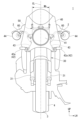
図2に示すように、自動二輪車1は、車幅方向中央側に配置されるヘッドライト41と、ヘッドライト41よりも車幅方向外側に配置される左右一対のウインカ42と、各ウインカ42に繋がるウインカハーネス43と、ヘッドライト41よりも車幅方向外側に配置される左右一対のミラー44と、各ミラー44を支持するミラーステー60と、を備える。
As shown in FIG. 2, the
車両前面視で、ヘッドライト41は、円形状に形成されている。ヘッドライト41は、車体左右中心線CL上に配置されている。車両前面視で、ヘッドライト41は、車体左右中心線CLを対称軸とする線対称の形状である。図5の車両前面視で、ヘッドライト41の車幅方向外側部は、フロントフォーク31の中心線C1と重なっている。
The
図2に示すように、ウインカ42は、ミラー44とは別体に設けられている。ウインカ42は、ミラー44の下方に配置されている。図5の車両前面視で、ウインカ42は、ヘッドライト41の車両上下方向の範囲Vh外に配置されている。ここで、ヘッドライト41の車両上下方向の範囲Vhは、車両前面視におけるヘッドライト41の上端と下端との間の範囲を意味する。ウインカ42は、ヘッドライト41よりも下側に配置されている。図5の車両前面視で、ウインカ42は、フロントフォーク31よりも車幅方向外側に配置されている。
As shown in FIG. 2, the
図2に示すように、ウインカ42は、フロントカウル40の左右側部に取り付けられている。ウインカ42は、車両を転舵するために動くステアリング機構30には取り付けられていない。ウインカ42は、フロントカウル40の左右側部から車幅方向外側に延びている。
As shown in FIG. 2, the turn signals 42 are attached to the left and right sides of the
図5に示すように、ウインカ42は、ウインカランプが収容されるランプ収容部42aと、ランプ収容部42aからフロントカウル40の左右側部に向かって延びるアーム部42bと、を一体に備える。
As shown in FIG. 5, the
図2に示すように、ウインカ42は、フロントカウル40の左右側部の前側に配置されている。車両前面視で、ウインカ42のランプ収容部42aは、フロントカウル40の左右側部と重なる。これにより、ウインカ42の光が直に運転者の視線に入ることを軽減することができる。
As shown in FIG. 2, the turn signals 42 are arranged on the front side of the left and right side portions of the
図5に示すように、ウインカハーネス43は、ウインカ42のアーム部42bの車幅方向内側部から引き出された後、吸気ダクト39の車幅方向内側を通り、ミラーステー60に向かって上方に延びている。ウインカハーネス43の中途部には、筒状のカバー部46が設けられている。車両前面視で、カバー部46は、カバー部46の上端が車幅方向外側に位置し、かつ、カバー部46の下端が車幅方向内側に位置するように傾斜して延びている。ウインカハーネス43は、カバー部46の上端から引き出された後、ヘッドライト41の後方に向かって車幅方向内側に湾曲しつつ延びている。
As shown in FIG. 5, the
ミラー44は、円形状に形成されている。車両前面視で、ミラー44の上部は、ハンドル2と重なっている。車両前面視で、ミラー44は、ウインカ42よりも車幅方向外側に配置されている。ミラー44は、ヘッドライト41の車両上下方向の範囲Vh内に配置されている。
The
ミラーステー60の一部は、ウインカ42の車幅方向の範囲Ws内に配置されている。ここで、ウインカ42の車幅方向の範囲Wsは、車両前面視におけるウインカ42の車幅方向内端と車幅方向外端との間の範囲を意味する。車両前面視で、ミラーステー60の一部は、フロントフォーク31と重なっている。図7に示すように、ミラーステー60は、ヘッドライトステー70と一体に設けられている。ミラーステー60は、ヘッドライトステー70と共にステーユニット50を構成している。
A portion of the
<ステーユニット>
図7に示すように、ステーユニット50は、ヘッドパイプ21(図1参照)に連結されるベースステー51と、ミラー44を支持するミラーステー60と、ヘッドライト41を支持するヘッドライトステー70と、メーター48を支持するメーターステー80と、を一体に備える。
<Stay unit>
As shown in FIG. 7, the
ベースステー51は、車幅方向中央に設けられている。図4に示すように、ベースステー51は、ヘッドパイプ21とヘッドライト41との間に設けられている。ベースステー51は、ヘッドパイプ21からヘッドライト41に向かって前方に延びている。図8に示すように、ベースステー51は、左右一対のベース側壁部52と、各ベース側壁部52の上端同士を連結するベース上壁部53と、を一体に備える。
The
各ベース側壁部52の前部は、ミラーステー60の後部外周面に沿うように弧状に形成されている。各ベース側壁部52の後部には、ベースステー51固定用のボルト等が挿通される貫通孔54が形成されている。ベース上壁部53は、ヘッドパイプ21から前方に向かって一様の左右幅(車幅方向の長さ)で延びた後、前方に向かうに従って左右幅が大きくなるように形成されている。
The front portion of each base
<ミラーステー>
図5に示すように、ミラーステー60は、ヘッドライト41の車両上下方向の範囲Vh内に配置されている。車両前面視で、ミラーステー60の全部は、ヘッドライト41の上端と下端との間に配置されている。図4に示すように、ミラーステー60は、ベースステー51を介してヘッドパイプ21に固定されている。ミラーステー60は、車両を転舵するためのステアリング機構30には取り付けられていない。
<Mirror stay>
As shown in FIG. 5, the
図7に示すように、ミラーステー60は、ミラー44を支持するミラー支持本体部61と、ミラー支持本体部61を支持する筒状の支持筒部62と、支持筒部62とベースステー51とを連結するように延びる連結延在部63と、ウインカハーネス43が取り付けられるウインカハーネス取付部64と、を一体に備える。
As shown in FIG. 7, the
ミラー支持本体部61は、左右一対設けられている。図5に示すように、ミラー支持本体部61は、ヘッドライト41よりも車幅方向外側に配置されている。車両前面視で、ミラー支持本体部61は、支持筒部62の上端から車幅方向外側に向かうに従って上側に位置するように傾斜して延びた後、車幅方向外側に延びている。その後、車両前面視で、ミラー支持本体部61は、車幅方向外側に向かうに従って下側に位置するように湾曲しつつ傾斜して延びた後、ミラー44の前部に連結されている。車両前面視で、ミラー支持本体61において支持筒部62とミラー44との間の部分は、ウインカ42の車幅方向の範囲Ws内に配置されている。
A pair of left and right mirror support
支持筒部62は、円筒状に形成されている。車両前面視で、支持筒部62は、支持筒部62の上端が車幅方向外側に位置し、かつ、支持筒部62の下端が車幅方向内側に位置するように傾斜して延びている。車両前面視で、支持筒部62の車幅方向内端は、フロントフォーク31と重なっている。
The
図8に示すように、連結延在部63は、各支持筒部62同士を連結するように車幅方向に延びている。連結延在部63は、ベースステー51に連結される部分(車幅方向中央側の部分)において車幅方向に延びた後、車幅方向外側に向かうに従って下側に位置するように傾斜して延びている。例えば、連結延在部63の車幅方向中央側の部分は、ベースステー51に溶接されている。なお、図8では、ミラーステー60を構成するミラー支持本体部61の図示は省略している。図5の車両前面視で、連結延在部63のうちヘッドライト41よりも車幅方向外側に位置する部分は、フロントフォーク31と重なっている。
As shown in FIG. 8, the connecting
図8に示すように、ウインカハーネス取付部64は、支持筒部62の車幅方向外側部(連結延在部63が連結される部分とは反対側の部分)に設けられている。ウインカハーネス取付部64は、支持筒部62の車幅方向外側部から車幅方向外方に突出する凸形状に形成されている。図5に示すように、ウインカハーネス取付部64には、ウインカハーネス43を拘束するための拘束部材45(例えば、ハーネスクランプ)が溶接されている。
As shown in FIG. 8, the turn signal
なお、拘束部材45は、ウインカハーネス取付部64に対して着脱可能に取り付けられていてもよい。例えば、拘束部材45は、結束バンド又はテープ等であってもよい。例えば、拘束部材45の態様は、要求仕様に応じて変更することができる。
Note that the restraining
ウインカハーネス取付部64は、ヘッドライト41よりも車幅方向外側に配置されている。図5の車両前面視で、ウインカハーネス取付部64は、ヘッドライト41の車幅方向の範囲Wh外に配置されている。ここで、ヘッドライト41の車幅方向の範囲Whは、車両前面視におけるヘッドライト41の車幅方向一端(左端)と車幅方向他端(右端)との間の範囲を意味する。図5の車両前面視で、ウインカハーネス取付部64は、フロントフォーク31の中心線C1よりも車幅方向外側に配置されている。車両前面視で、ウインカハーネス取付部64の突出端(車幅方向外端)は、フロントフォーク31よりも車幅方向外側に配置されている。
The turn signal
図5の車両前面視で、ウインカハーネス取付部64は、ヘッドライト41の車両上下方向の範囲Vh内に配置されている。車両前面視で、ウインカハーネス取付部64は、ウインカ42の車幅方向の範囲Ws内に配置されている。
In the front view of the vehicle in FIG. 5, the turn signal
図3に示すように、カウル取り付け状態において、ウインカハーネス取付部64(図5参照)は、フロントカウル40によって覆われている。フロントカウル40は、車両側面視でウインカハーネス取付部64と重なっている。フロントカウル40は、ヘッドライト41の後方に位置する部材を、ウインカ42及びミラー44よりも車幅方向内側の位置から覆うように構成されている。
As shown in FIG. 3, the turn signal harness attachment portion 64 (see FIG. 5) is covered by the
<ヘッドライトステー>
図8に示すように、ヘッドライトステー70は、ヘッドライト41(図7参照)の上部を支持する左右一対の上支持本体部71と、各上支持本体部71と連結延在部63とを連結するように前後方向に延びる第一上延在部72と、各第一上延在部72の前部同士を連結する第二上延在部73と、ヘッドライト41の下部を支持する下支持本体部74と、第一上延在部72の下方において上下方向に延びる左右一対の第一下延在部75と、各第一下延在部75の下部同士を連結するように車幅方向に延びる第二下延在部76と、第一上延在部72と第一下延在部75とを連結するように上下方向に延びる上下延在部77と、を一体に備える。図4に示すように、ヘッドライトステー70は、カウル取り外し状態において外部に露出している。
<Headlight stay>
As shown in FIG. 8, the
図8に示すように、上支持本体部71は、第一上延在部72の前部から上方に延びている。上支持本体部71は、ヘッドライト41(図7参照)の上部の左右側部に対応して左右一対設けられている。上支持本体部71には、ヘッドライト41の上部を固定するためのボルト等が設けられている。
As shown in FIG. 8, the upper
第一上延在部72は、ミラーステー60の連結延在部63においてベースステー51のベース上壁部53の車幅方向外端に対応する部分から前側に向かうに従って車幅方向外側に位置するように傾斜して延びている。例えば、第一上延在部72の前部は、上支持本体部71に溶接されている。例えば、第一上延在部72の後端は、ミラーステー60の連結延在部63に溶接されている。
The first
第二上延在部73は、各第一上延在部72の前部の車幅方向内側部同士を連結するように車幅方向に直線状に延びている。例えば、第二上延在部73の車幅方向外端は、第一上延在部72の前部の車幅方向内側面に溶接されている。
The second
下支持本体部74は、第二下延在部76の後部の車幅方向中央部から上方に延びるとともに車幅方向に延びている。下支持本体部74は、ヘッドライト41(図7参照)の下部の左右側部に跨るように車幅方向に延びている。下支持本体部74の車幅方向外側部には、ヘッドライト41の下部を固定するためのボルト等が設けられている。
The lower support
第一下延在部75は、ミラーステー60の連結延在部63において第一上延在部72の連結部よりも車幅方向外側の部分から下側に向かうに従って前側に位置するように傾斜して延びている。例えば、第一下延在部75の上端は、ミラーステー60の連結延在部63に溶接されている。第一下延在部75の上部は、上下延在部77を介して第一上延在部72の前後方向中央部に連結されている。
The first lower extending
第二下延在部76は、各第一下延在部75の下部の前部同士を連結するように車幅方向に延びている。第二下延在部76は、車両上下方向に厚みを有する板状に形成されている。第二下延在部76の車幅方向外側部には、ラバーマウント等の弾性部材79が取り付けられている。
The second lower extending
<メーターステー>
図8に示すように、メーターステー80は、メーター48(図7参照)の車幅方向外側部を支持する左右一対の側部支持部81と、メーター48の前部を支持する前部支持部82と、を備える。メーターステー80は、ヘッドライトステー70と一体に設けられている。
<Meter stay>
As shown in FIG. 8, the
各側部支持部81は、第一上延在部72と一体に設けられている。側部支持部81は、第一上延在部72の前後方向中央部から車幅方向内側に向かって湾曲しつつ延びている。例えば、側部支持部81の車幅方向外端は、第一上延在部72に溶接されている。側部支持部81の車幅方向内側部には、ラバーマウント等の弾性部材83が取り付けられている。
Each
前部支持部82は、第二上延在部73と一体に設けられている。前部支持部82は、第二上延在部73の車幅方向中央部から前上方に延びている。例えば、前部支持部82の後端は、第二上延在部73に溶接されている。前部支持部82には、ラバーマウント等の弾性部材84が取り付けられている。
The
<ウインカハーネスの配置>
図6に示すように、ウインカハーネス43は、ウインカ42から延びた後、拘束部材45等を介して、ミラーステー60を構成する支持筒部62の車幅方向外側に取り付けられている。ウインカハーネス43は、ミラーステー60を構成する支持筒部62及び連結延在部63の前側を通ってヘッドライト41の後方に向けて延びている。
<Turn signal harness arrangement>
As shown in FIG. 6, the
図7に示すように、ウインカハーネス43は、ヘッドライト41の後方においてメインハーネスと繋がっている。なお、図示はしないが、メーター48やハンドル2、ヘッドライト41に繋がる各ハーネスは、ヘッドライト41の後方においてメインハーネス90と繋がっている。
As shown in FIG. 7, the
ウインカハーネス43においてミラーステー60からメインハーネス90まで延びる部分は、シート8(図1参照)に着座した乗員(運転者)からは目視されない位置に配置されている。例えば、ウインカハーネス43の少なくとも一部は、連結延在部63の斜め前方(例えば前下方)に配置されていてもよい。これにより、運転者の目線でウインカハーネス43と連結延在部63とが重なるため、ウインカハーネス43が見えなくなる。
A portion of the
<作用効果>
以上説明したように、上記実施形態の自動二輪車1は、車両の車幅方向中央側に配置されるヘッドライト41と、ヘッドライト41よりも車幅方向外側に配置されるウインカ42と、ウインカ42に繋がるウインカハーネス43と、ヘッドライト41よりも車幅方向外側に配置され、ミラー44を支持するミラーステー60と、を備え、ミラーステー60は、ウインカハーネス43が取り付けられるウインカハーネス取付部64を有し、ウインカハーネス取付部64は、ヘッドライト41よりも車幅方向外側に配置されている。
この構成によれば、ウインカハーネス取付部64がヘッドライト41の車幅方向の範囲Wh内に配置されている場合と比較して、車幅方向中央側に配置されるヘッドライト41周辺が複雑化することを抑制することができる。したがって、車幅方向中央側の構造が複雑化することを抑制することができる。
上記実施形態では、車両前面視で、ヘッドライト41の車幅方向の範囲Wh内にメーター48及びトップブリッジ32等が配置され、さらにメーター48やハンドル2、ヘッドライト41の各種ハーネスがヘッドライト41の後方でメインハーネス90に繋がっているため、ヘッドライト41よりも車幅方向外側に配置されるミラーステー60のウインカハーネス取付部64にウインカハーネス43が取り付けられることで、車幅方向中央側の構造が複雑化することを抑制することができる。加えて、既存のミラーステー60にウインカハーネス43を取り付けているため、ウインカハーネス43を取り付けるためにウインカハーネス43を取り付けるためのステーを別途設ける必要がなくなり、部品点数を削減することができる。
<Effect>
As described above, the
According to this configuration, the area around the
In the above embodiment, when viewed from the front of the vehicle, the
上記実施形態では、ウインカハーネス取付部64は、フロントフォーク31の中心線C1よりも車幅方向外側に配置されている。
この構成によれば、ウインカハーネス取付部64がフロントフォーク31の中心線C1よりも車幅方向内側に配置されている場合と比較して、フロントフォーク31の中心線C1よりも車幅方向内側における車幅方向中央側の構造が複雑化することを抑制することができる。
In the embodiment described above, the turn signal
According to this configuration, compared to the case where the turn signal
上記実施形態では、ウインカハーネス取付部64は、ヘッドライト41の車両上下方向の範囲Vh内に配置されている。
この構成によれば、ウインカハーネス取付部64がヘッドライト41の車両上下方向の範囲Vh外に配置されている場合と比較して、ウインカハーネス取付部64から延びるウインカハーネス43を車幅方向中央側で繋ぐ場合にウインカハーネス43を短くすることができる。したがって、ウインカハーネス43を好適な位置で取り付けることができる。
上記実施形態では、ウインカハーネス43がヘッドライト41の後方でメインハーネス90に繋がっているため、ウインカハーネス取付部64からメインハーネス90の繋ぎ部までの距離を短くすることができ、ウインカハーネス43を短くするように好適な位置で取り付けることができる。
In the embodiment described above, the turn signal
According to this configuration, the
In the embodiment described above, since the
上記実施形態では、ウインカ42は、ヘッドライト41の車両上下方向の範囲Vh外に配置されている。
この構成によれば、ウインカ42がヘッドライト41の車両上下方向の範囲Vh内に配置されている場合と比較して、ヘッドライト41の車両上下方向の範囲Vh内における構造が複雑化することを抑制することができる。
In the embodiment described above, the
According to this configuration, the structure within the range Vh of the
上記実施形態では、ウインカ42は、ヘッドライト41よりも車両下側に配置されている。
この構成によれば、ウインカ42がヘッドライト41よりも車両上側に配置されている場合と比較して、ウインカ42の光が直に運転者の視線に入ることを軽減することができる。
In the embodiment described above, the turn signals 42 are arranged below the
According to this configuration, compared to the case where the turn signals 42 are arranged above the
上記実施形態では、ウインカハーネス取付部64は、ウインカ42の車幅方向の範囲Ws内に配置されている。
この構成によれば、ウインカハーネス取付部64がウインカ42の車幅方向の範囲Ws外に配置されている場合と比較して、ウインカハーネス取付部64とウインカ42との間を延びるウインカハーネス43を短くすることができる。加えて、車幅方向中央側の構造が複雑化することを抑制することができる。
In the embodiment described above, the turn signal
According to this configuration, the
上記実施形態では、ミラーステー60は、ヘッドライト41を支持するヘッドライトステー70と一体に設けられている。
この構成によれば、ミラーステー60がヘッドライトステー70と別体に設けられている場合と比較して、部品点数を削減することができる。加えて、ヘッドライトステー70付近に別途ミラーステー60を取り付けるための部品を必要としないため、車幅方向中央側に配置されるヘッドライト41周辺が複雑化することを抑制することができる。
In the embodiment described above, the
According to this configuration, the number of parts can be reduced compared to the case where the
上記実施形態では、車両前部を覆うフロントカウル40を備え、フロントカウル40は、車両側面視でウインカハーネス取付部64と重なる。
この構成によれば、車両側方からウインカハーネス取付部64を見えなくすることができるため、外観性が向上する。加えて、車両転倒時にフロントカウル40によってウインカハーネス取付部64を保護することができるため、ウインカハーネス43の断線のリスクを低減することができる。
The embodiment described above includes a
According to this configuration, the turn signal
上記実施形態では、ウインカハーネス43は、ミラーステー60の車幅方向外側に取り付けられるとともに、ミラーステー60の車両前側を通る。
この構成によれば、ウインカハーネス43がミラーステー60の車両後側を通る場合と比較して、ミラーステー60の車両後側にフロントフォーク31が配置されている場合にウインカハーネス43がフロントフォーク31と干渉することを防ぐことができる。加えて、運転者から見てウインカハーネス43がミラーステー60の奥側に配置されるため、運転者からウインカハーネス43を見えにくくすることができる。
In the embodiment described above, the
According to this configuration, the
上記実施形態では、ミラーステー60及びウインカ42は、車両を転舵するために動くステアリング機構30には取り付けられていない。
この構成によれば、ミラーステー60及びウインカ42がステアリング機構30に取り付けられている場合と比較して、車両の転舵時にウインカハーネス43がステアリング機構30と干渉することを抑制することができる。
In the embodiment described above, the
According to this configuration, compared to the case where the
上記実施形態では、ウインカ42は、ミラー44とは別体に設けられていることで、以下の効果を奏する。
この構成によれば、ミラー44とは別体のウインカ42を備えた構成において、車幅方向中央側の構造が複雑化することを抑制することができる。
In the embodiment described above, the
According to this configuration, in a configuration including the
<変形例>
なお、上記実施形態では、ウインカハーネス取付部は、フロントフォークの中心線よりも車幅方向外側に配置されている例を挙げて説明したが、これに限らない。例えば、ウインカハーネス取付部は、フロントフォークの中心線よりも車幅方向内側に配置されていてもよい。例えば、ウインカハーネス取付部は、車幅方向中央側に配置されるヘッドライトよりも車幅方向外側に配置されていればよい。例えば、ウインカハーネス取付部の配置態様は、要求仕様に応じて変更することができる。
<Modified example>
In addition, although the above-mentioned embodiment has been described with reference to an example in which the turn signal harness attachment portion is disposed on the outer side in the vehicle width direction than the center line of the front fork, the present invention is not limited to this. For example, the turn signal harness attachment portion may be arranged inside the center line of the front fork in the vehicle width direction. For example, the turn signal harness attachment portion may be disposed on the outer side in the vehicle width direction than the headlight, which is disposed on the center side in the vehicle width direction. For example, the arrangement of the turn signal harness attachment portion can be changed depending on required specifications.
上記実施形態では、ウインカハーネス取付部は、ヘッドライトの車両上下方向の範囲内に配置されている例を挙げて説明したが、これに限らない。例えば、ウインカハーネス取付部は、ヘッドライトの車両上下方向の範囲外に配置されていてもよい。例えば、ヘッドライトの車両上下方向の範囲に対するウインカハーネス取付部の配置態様は、要求仕様に応じて変更することができる。 In the embodiment described above, the turn signal harness attachment portion is arranged within the range of the headlight in the vertical direction of the vehicle, but the present invention is not limited thereto. For example, the turn signal harness attachment portion may be arranged outside the range of the headlight in the vehicle vertical direction. For example, the arrangement of the turn signal harness attachment portion with respect to the range of the headlight in the vehicle vertical direction can be changed depending on required specifications.
上記実施形態では、ウインカは、ヘッドライトの車両上下方向の範囲外に配置されている例を挙げて説明したが、これに限らない。例えば、ウインカは、ヘッドライトの車両上下方向の範囲内に配置されていてもよい。例えば、ウインカの配置態様は、要求仕様に応じて変更することができる。 In the above embodiment, the turn signal is arranged outside the range of the headlight in the vertical direction of the vehicle, but the present invention is not limited thereto. For example, the blinker may be arranged within the range of the headlight in the vehicle vertical direction. For example, the arrangement of the turn indicators can be changed depending on required specifications.
上記実施形態では、ウインカは、ヘッドライトよりも車両下側に配置されている例を挙げて説明したが、これに限らない。例えば、ウインカは、ヘッドライトよりも車両上側に配置されていてもよい。例えば、ヘッドライトに対するウインカの配置位置は、要求仕様に応じて変更することができる。 In the embodiment described above, the turn signal is arranged below the headlights of the vehicle, but the present invention is not limited thereto. For example, the turn signal may be placed above the headlights of the vehicle. For example, the position of the turn signal relative to the headlight can be changed depending on required specifications.
上記実施形態では、ウインカハーネス取付部は、ウインカの車幅方向の範囲内に配置されている例を挙げて説明したが、これに限らない。例えば、ウインカハーネス取付部は、ウインカの車幅方向の範囲外に配置されていてもよい。例えば、ウインカの車幅方向の範囲に対するウインカハーネス取付部の配置態様は、要求仕様に応じて変更することができる。 In the embodiment described above, the turn signal harness attachment portion is arranged within the range of the turn signal in the vehicle width direction, but the present invention is not limited thereto. For example, the turn signal harness attachment portion may be arranged outside the range of the turn signal in the vehicle width direction. For example, the arrangement of the turn signal harness attachment portion with respect to the range of the turn signal in the vehicle width direction can be changed depending on required specifications.
上記実施形態では、ミラーステーは、ヘッドライトを支持するヘッドライトステーと一体に設けられている例を挙げて説明したが、これに限らない。例えば、ミラーステーは、ヘッドライトステーと別体に設けられていてもよい。例えば、ミラーステーの態様は、要求仕様に応じて変更することができる。 In the above embodiment, the mirror stay is described as being provided integrally with a headlight stay that supports a headlight, but the mirror stay is not limited thereto. For example, the mirror stay may be provided separately from the headlight stay. For example, the aspect of the mirror stay can be changed according to required specifications.
上記実施形態では、車両前部を覆うフロントカウルを備え、フロントカウルは、車両側面視でウインカハーネス取付部と重なる例を挙げて説明したが、これに限らない。例えば、フロントカウルは、車両側面視でウインカハーネス取付部と重なっていなくてもよい。例えば、ウインカハーネス取付部に対するフロントカウルの設置態様は、要求仕様に応じて変更することができる。例えば、車両は、フロントカウルを備えていなくてもよい。例えば、フロントカウルの設置態様は、要求仕様に応じて変更することができる。 In the embodiment described above, the front cowl is provided with a front cowl that covers the front portion of the vehicle, and the front cowl overlaps with the turn signal harness mounting portion when viewed from the side of the vehicle. However, the present invention is not limited to this. For example, the front cowl does not need to overlap the turn signal harness mounting portion when viewed from the side of the vehicle. For example, the manner in which the front cowl is installed with respect to the turn signal harness attachment portion can be changed depending on required specifications. For example, the vehicle may not include a front cowl. For example, the manner in which the front cowl is installed can be changed depending on required specifications.
上記実施形態では、ウインカハーネスは、ミラーステーの車幅方向外側に取り付けられるとともに、ミラーステーの車両前側を通る例を挙げて説明したが、これに限らない。例えば、ウインカハーネスは、ミラーステーの車両後側を通っていてもよい。例えば、ウインカハーネスの配置態様は、要求仕様に応じて変更することができる。 In the embodiment described above, the turn signal harness is attached to the outside of the mirror stay in the vehicle width direction, and is explained as passing through the vehicle front side of the mirror stay, but the present invention is not limited thereto. For example, the turn signal harness may pass through the rear side of the mirror stay in the vehicle. For example, the arrangement of the turn signal harness can be changed depending on required specifications.
上記実施形態では、ミラーステー及びウインカは、車両を転舵するために動くステアリング機構には取り付けられていない例を挙げて説明したが、これに限らない。例えば、ミラーステー及びウインカは、ステアリング機構に取り付けられていてもよい。例えば、ステアリング機構(車両を転舵するために動く可動部)に対するミラーステー及びウインカの取り付け態様は、要求仕様に応じて変更することができる。 In the above embodiment, the mirror stay and the blinker are not attached to a steering mechanism that moves to steer the vehicle, but the present invention is not limited thereto. For example, the mirror stay and the turn signal may be attached to the steering mechanism. For example, the manner in which the mirror stay and turn signals are attached to the steering mechanism (a movable part that moves to steer the vehicle) can be changed depending on required specifications.
上記実施形態では、ウインカは、ミラーとは別体に設けられている例を挙げて説明したが、これに限らない。例えば、ウインカは、ミラーと一体に設けられていてもよい。例えば、ウインカランプは、ミラーの前部に内蔵されていてもよい。例えば、ウインカ及びミラーの構成態様は、要求仕様に応じて変更することができる。 In the above embodiment, the turn signal is provided separately from the mirror, but the present invention is not limited thereto. For example, the turn signal may be provided integrally with the mirror. For example, the turn signal lamp may be built into the front part of the mirror. For example, the configuration of the turn signals and mirrors can be changed according to required specifications.
上記実施形態では、ウインカハーネスは、ウインカのアーム部の車幅方向内側部から引き出された後、吸気ダクトの車幅方向内側を通り、ミラーステーに向かって上方に延びている例を挙げて説明したが、これに限らない。例えば、図9に示すように、ウインカハーネス143は、ウインカ42のアーム部42bの車幅方向内側部から引き出された後、湾曲しつつ車幅方向外側に向かって延びていてもよい。その後、ウインカハーネス143は、吸気ダクト139の車幅方向外側を通り、ミラーステー160に向かって上方に延びていてもよい。例えば、ウインカハーネス143が所定長さよりも長い場合は、ウインカハーネス143を束ねた状態でウインカハーネス取付部に取り付けてもよい。例えば、ウインカハーネスの配置態様は、要求仕様に応じて変更することができる。
In the above embodiment, the turn signal harness is explained using an example in which the turn signal harness is pulled out from the inner side in the vehicle width direction of the arm portion of the turn signal, passes inside the intake duct in the vehicle width direction, and extends upward toward the mirror stay. However, it is not limited to this. For example, as shown in FIG. 9, the
上記実施形態では、駆動装置の一例としてエンジンを挙げて説明したが、これに限らない。例えば、駆動装置は、電動機等、エンジン(内燃機関)以外の装置であってもよい。例えば、駆動装置は、電動機、熱機関、流体機械等の原動機、又は前記原動機のうちの少なくとも2つを組み合わせた装置であってもよい。例えば、駆動装置の態様は、要求仕様に応じて変更することができる。 Although the above embodiment has been described using an engine as an example of the drive device, the present invention is not limited to this. For example, the drive device may be a device other than an engine (internal combustion engine), such as an electric motor. For example, the drive device may be a prime mover such as an electric motor, a heat engine, or a fluid machine, or a device that combines at least two of the prime movers. For example, the aspect of the drive device can be changed depending on required specifications.
上記実施形態では、鞍乗型車両の一例として車体側にエンジンを搭載した自動二輪車を例に挙げて説明したが、これに限らない。例えば、鞍乗型車両は、ユニットスイング式の自動二輪車であってもよい。例えば、鞍乗型車両の態様は、要求仕様に応じて変更することができる。 In the embodiment described above, a motorcycle with an engine mounted on the body side has been described as an example of a straddle-type vehicle, but the present invention is not limited to this. For example, the saddle type vehicle may be a unit swing type motorcycle. For example, the aspect of the straddle-type vehicle can be changed depending on required specifications.
なお、本発明は上記実施形態に限られるものではなく、自動二輪車以外の鞍乗型車両に適用してもよい。例えば、前記鞍乗型車両には、運転者が車体を跨いで乗車する車両全般が含まれ、自動二輪車(原動機付自転車及びスクータ型車両を含む)のみならず、三輪(前一輪且つ後二輪の他に、前二輪且つ後一輪の車両も含む)の車両も含まれる。また、本発明は、自動二輪車のみならず、自動車等の四輪(四輪バギー等)の車両にも適用可能である。
そして、上記実施形態における構成は本発明の一例であり、実施形態の構成要素を周知の構成要素に置き換える等、本発明の要旨を逸脱しない範囲で種々の変更が可能である。
Note that the present invention is not limited to the above-described embodiments, and may be applied to straddle-type vehicles other than motorcycles. For example, the straddle-type vehicle includes all vehicles in which the driver rides astride the body of the vehicle, and includes not only motorcycles (including motorized bicycles and scooter-type vehicles) but also three-wheeled vehicles (one front wheel and two rear wheels). In addition, vehicles with two wheels in the front and one wheel in the rear are also included. Further, the present invention is applicable not only to motorcycles but also to four-wheeled vehicles such as automobiles (four-wheeled buggies, etc.).
The configuration in the embodiment described above is an example of the present invention, and various changes can be made without departing from the gist of the present invention, such as replacing the constituent elements of the embodiment with well-known constituent elements.
1 自動二輪車(鞍乗型車両)
30 ステアリング機構(可動部)
40 フロントカウル
41 ヘッドライト
42 ウインカ
43 ウインカハーネス
44 ミラー
60 ミラーステー
64 ウインカハーネス取付部
70 ヘッドライトステー
C1 フロントフォークの中心線
Vh ヘッドライトの車両上下方向の範囲
Ws ウインカの車幅方向の範囲
1 Motorcycle (straddle type vehicle)
30 Steering mechanism (movable part)
40
Claims (11)
前記ヘッドライト(41)よりも車幅方向外側に配置されるウインカ(42)と、
前記ウインカ(42)に繋がるウインカハーネス(43)と、
前記ヘッドライト(41)よりも車幅方向外側に配置され、ミラー(44)を支持するミラーステー(60)と、を備え、
前記ミラーステー(60)は、
前記ヘッドライト(41)の後方で車幅方向に延びる延在部(63)と、
前記延在部(63)の両端に設けられる支持部(62)と、
前記支持部(62)によって支持される支持本体部(61)と、
前記ウインカハーネス(43)が取り付けられるウインカハーネス取付部(64)と、を有し、
前記ウインカハーネス取付部(64)は、前記ヘッドライト(41)よりも車幅方向外側かつ前記支持部(62)の車幅方向外側に配置されていることを特徴とする
鞍乗型車両。 a headlight (41) arranged at the center side of the vehicle in the vehicle width direction;
a turn signal (42) arranged outside the headlight (41) in the vehicle width direction;
a turn signal harness (43) connected to the turn signal (42);
a mirror stay (60) that is disposed outside the headlight (41) in the vehicle width direction and supports the mirror (44);
The mirror stay (60) is
an extending portion (63) extending in the vehicle width direction behind the headlight (41);
Support portions (62) provided at both ends of the extension portion (63);
a support body portion (61) supported by the support portion (62);
a turn signal harness attachment part (64) to which the turn signal harness (43) is attached;
The straddle-type vehicle is characterized in that the turn signal harness attachment portion (64) is disposed on the outer side in the vehicle width direction than the headlight (41) and on the outer side in the vehicle width direction of the support portion (62) .
請求項1に記載の鞍乗型車両。 The straddle-type vehicle according to claim 1, wherein the turn signal harness attachment portion (64) is disposed outward in the vehicle width direction from the center line (C1) of the front fork (31).
請求項1又は2に記載の鞍乗型車両。 The straddle-type vehicle according to claim 1 or 2, wherein the turn signal harness attachment portion (64) is disposed within a range (Vh) of the headlight (41) in the vehicle vertical direction.
請求項1から3の何れか一項に記載の鞍乗型車両。 The straddle-type vehicle according to any one of claims 1 to 3, wherein the turn signal (42) is arranged outside a range (Vh) of the headlight (41) in the vehicle vertical direction. .
請求項4に記載の鞍乗型車両。 The straddle-type vehicle according to claim 4, wherein the turn signal (42) is arranged below the headlight (41).
請求項1から5の何れか一項に記載の鞍乗型車両。 The saddle riding according to any one of claims 1 to 5, wherein the turn signal harness attachment portion (64) is disposed within a range (Ws) of the turn signal (42) in the vehicle width direction. type vehicle.
請求項1から6の何れか一項に記載の鞍乗型車両。 The saddle riding according to any one of claims 1 to 6, wherein the mirror stay (60) is provided integrally with a headlight stay (70) that supports the headlight (41). type vehicle.
前記フロントカウル(40)は、車両側面視で前記ウインカハーネス取付部(64)と重なることを特徴とする
請求項1から7の何れか一項に記載の鞍乗型車両。 It further includes a front cowl (40) that covers the front of the vehicle,
The straddle-type vehicle according to any one of claims 1 to 7, wherein the front cowl (40) overlaps the turn signal harness attachment portion (64) when viewed from a side of the vehicle.
請求項1から8の何れか一項に記載の鞍乗型車両。 9. The turn signal harness (43) is attached to the outside of the mirror stay (60) in the vehicle width direction and passes through the vehicle front side of the mirror stay (60). A straddle-type vehicle described in .
請求項1から9の何れか一項に記載の鞍乗型車両。 The mirror stay (60) and the turn signal (42) are not attached to a movable part (30) that moves to steer the vehicle. The saddle type vehicle described.
請求項1から10の何れか一項に記載の鞍乗型車両。 The straddle-type vehicle according to any one of claims 1 to 10, wherein the turn signal (42) is provided separately from the mirror (44).
Priority Applications (1)
| Application Number | Priority Date | Filing Date | Title |
|---|---|---|---|
| JP2021156528A JP7369749B2 (en) | 2021-09-27 | 2021-09-27 | saddle type vehicle |
Applications Claiming Priority (1)
| Application Number | Priority Date | Filing Date | Title |
|---|---|---|---|
| JP2021156528A JP7369749B2 (en) | 2021-09-27 | 2021-09-27 | saddle type vehicle |
Publications (2)
| Publication Number | Publication Date |
|---|---|
| JP2023047556A JP2023047556A (en) | 2023-04-06 |
| JP7369749B2 true JP7369749B2 (en) | 2023-10-26 |
Family
ID=85779181
Family Applications (1)
| Application Number | Title | Priority Date | Filing Date |
|---|---|---|---|
| JP2021156528A Active JP7369749B2 (en) | 2021-09-27 | 2021-09-27 | saddle type vehicle |
Country Status (1)
| Country | Link |
|---|---|
| JP (1) | JP7369749B2 (en) |
Citations (3)
| Publication number | Priority date | Publication date | Assignee | Title |
|---|---|---|---|---|
| JP2001213375A (en) | 2000-02-07 | 2001-08-07 | Honda Motor Co Ltd | Rear view mirror with blinker, and vehicle such as motorcycle therewith |
| JP2015227105A (en) | 2014-05-30 | 2015-12-17 | ヤマハ発動機株式会社 | Mirror device with turn indicator light and saddle-riding type vehicle with the same |
| WO2020129978A1 (en) | 2018-12-18 | 2020-06-25 | 本田技研工業株式会社 | Decorative molded component |
Family Cites Families (1)
| Publication number | Priority date | Publication date | Assignee | Title |
|---|---|---|---|---|
| JPS58188733A (en) * | 1982-04-28 | 1983-11-04 | Teruaki Yoshida | Direction indicator device for back mirror |
-
2021
- 2021-09-27 JP JP2021156528A patent/JP7369749B2/en active Active
Patent Citations (3)
| Publication number | Priority date | Publication date | Assignee | Title |
|---|---|---|---|---|
| JP2001213375A (en) | 2000-02-07 | 2001-08-07 | Honda Motor Co Ltd | Rear view mirror with blinker, and vehicle such as motorcycle therewith |
| JP2015227105A (en) | 2014-05-30 | 2015-12-17 | ヤマハ発動機株式会社 | Mirror device with turn indicator light and saddle-riding type vehicle with the same |
| WO2020129978A1 (en) | 2018-12-18 | 2020-06-25 | 本田技研工業株式会社 | Decorative molded component |
Also Published As
| Publication number | Publication date |
|---|---|
| JP2023047556A (en) | 2023-04-06 |
Similar Documents
| Publication | Publication Date | Title |
|---|---|---|
| KR101634029B1 (en) | Saddled vehicle | |
| US11279435B2 (en) | Operation unit structure of straddle-type vehicle, and straddle-type vehicle | |
| JP5905091B2 (en) | Saddle riding | |
| JP5816715B2 (en) | Saddle riding | |
| US7637342B2 (en) | Straddle type vehicle | |
| JP5793932B2 (en) | Saddle riding vehicle | |
| JP2015033900A (en) | Fitting structure of front cowl stay in saddle-riding type vehicle | |
| JP4607745B2 (en) | Engine support structure for motorcycles | |
| JP2009234424A (en) | Harness retaining structure for saddle riding type vehicle | |
| JP5764025B2 (en) | Saddle riding | |
| JP5098103B2 (en) | Headlight support structure for saddle-ride type vehicles | |
| JP7369749B2 (en) | saddle type vehicle | |
| WO2019172380A1 (en) | Control unit arrangement structure for saddle riding-type vehicle | |
| JP5316033B2 (en) | Motorcycle headlamp unit mounting structure | |
| JP5775914B2 (en) | Cable routing structure for electrical components in saddle-ride type vehicles | |
| JPWO2017169106A1 (en) | Saddle riding vehicle | |
| JP7115896B2 (en) | straddle-type vehicle | |
| JP6564129B2 (en) | Lighting device and saddle riding type vehicle | |
| JP7210624B2 (en) | straddle-type vehicle | |
| JP2014065422A (en) | Motor cycle | |
| JP7293274B2 (en) | straddle-type vehicle | |
| JP7234279B2 (en) | straddle-type vehicle | |
| CN217753957U (en) | Electrical component arrangement structure | |
| JP7456981B2 (en) | saddle type vehicle | |
| JP7354204B2 (en) | saddle type vehicle |
Legal Events
| Date | Code | Title | Description |
|---|---|---|---|
| A621 | Written request for application examination |
Free format text: JAPANESE INTERMEDIATE CODE: A621 Effective date: 20220530 |
|
| A131 | Notification of reasons for refusal |
Free format text: JAPANESE INTERMEDIATE CODE: A131 Effective date: 20230606 |
|
| A521 | Request for written amendment filed |
Free format text: JAPANESE INTERMEDIATE CODE: A523 Effective date: 20230807 |
|
| TRDD | Decision of grant or rejection written | ||
| A01 | Written decision to grant a patent or to grant a registration (utility model) |
Free format text: JAPANESE INTERMEDIATE CODE: A01 Effective date: 20231003 |
|
| A61 | First payment of annual fees (during grant procedure) |
Free format text: JAPANESE INTERMEDIATE CODE: A61 Effective date: 20231016 |
|
| R150 | Certificate of patent or registration of utility model |
Ref document number: 7369749 Country of ref document: JP Free format text: JAPANESE INTERMEDIATE CODE: R150 |