JP7366689B2 - Image processing device, image processing method and program - Google Patents
Image processing device, image processing method and program Download PDFInfo
- Publication number
- JP7366689B2 JP7366689B2 JP2019197999A JP2019197999A JP7366689B2 JP 7366689 B2 JP7366689 B2 JP 7366689B2 JP 2019197999 A JP2019197999 A JP 2019197999A JP 2019197999 A JP2019197999 A JP 2019197999A JP 7366689 B2 JP7366689 B2 JP 7366689B2
- Authority
- JP
- Japan
- Prior art keywords
- evaluation
- display
- image processing
- color
- color signal
- Prior art date
- Legal status (The legal status is an assumption and is not a legal conclusion. Google has not performed a legal analysis and makes no representation as to the accuracy of the status listed.)
- Active
Links
- 238000012545 processing Methods 0.000 title claims description 68
- 238000003672 processing method Methods 0.000 title claims 2
- 238000011156 evaluation Methods 0.000 claims description 178
- 238000003384 imaging method Methods 0.000 claims description 23
- 238000013507 mapping Methods 0.000 claims description 6
- 239000011159 matrix material Substances 0.000 claims description 6
- 239000003086 colorant Substances 0.000 claims description 4
- 230000004044 response Effects 0.000 claims description 4
- 238000006243 chemical reaction Methods 0.000 description 45
- 238000000034 method Methods 0.000 description 31
- 238000010586 diagram Methods 0.000 description 14
- 230000006870 function Effects 0.000 description 6
- 230000000694 effects Effects 0.000 description 2
- 238000012935 Averaging Methods 0.000 description 1
- 238000013459 approach Methods 0.000 description 1
- 230000006835 compression Effects 0.000 description 1
- 238000007906 compression Methods 0.000 description 1
Images


Landscapes
- Image Processing (AREA)
- Testing, Inspecting, Measuring Of Stereoscopic Televisions And Televisions (AREA)
- Color Image Communication Systems (AREA)
Description
本発明は、物体の色を評価するための画像処理技術に関する。 The present invention relates to an image processing technique for evaluating the color of an object.
従来、画像においてユーザに指定された領域の色を評価する技術が知られている。特許文献1は、画像において指定された領域の色がプリンタを用いてどのように表現されるかを、色空間上の3Dオブジェクトで表示する技術を開示している。 2. Description of the Related Art Conventionally, techniques are known for evaluating the color of an area specified by a user in an image. Patent Document 1 discloses a technique for displaying, as a 3D object in a color space, how the color of a designated area in an image is expressed using a printer.
しかしながら、特許文献1では、対象の画像が物体を撮像して得られた撮像画像である場合に、実物の色がどのような色であるかを評価することはできないという課題があった。 However, Patent Document 1 has a problem in that when the target image is a captured image obtained by capturing an object, it is not possible to evaluate what color the actual color is.
本発明は、上記課題に鑑みてなされたものであり、物体の撮像画像を基に、実物の色を評価するための処理を提供することを目的とする。 The present invention has been made in view of the above problems, and an object of the present invention is to provide processing for evaluating the color of an actual object based on a captured image of the object.
上記課題を解決するために、本発明に係る画像処理装置は、物体を撮像して得られる撮像画像データを取得する取得手段と、前記撮像画像データが表す撮像画像に含まれる各画素の第1色信号値を前記物体の輝度に対して非線形な色信号値を得るための第1ルックアップテーブルを用いて表示手段の特性に応じた第2色信号値に変換することによって、表示画像データを生成する生成手段と、前記表示画像データが表す表示画像においてユーザに指定された複数の領域に対応する色の評価値を、前記物体の輝度に対して線形な評価値を得るための第2ルックアップテーブルを用いて算出する算出手段と、前記複数の領域と、前記評価値と、を対応付けて前記表示手段に表示する表示制御手段と、を有することを特徴とする。 In order to solve the above problems, an image processing device according to the present invention includes an acquisition unit that acquires captured image data obtained by imaging an object, and a first The display image data is converted into a second color signal value according to the characteristics of the display means using a first lookup table for obtaining a color signal value that is non-linear with respect to the luminance of the object. a second look for generating evaluation values of colors corresponding to a plurality of areas specified by a user in a display image represented by the display image data, which are linear with respect to the brightness of the object; The present invention is characterized in that it has a calculation means that calculates using an up-table , and a display control means that associates the plurality of regions and the evaluation value and displays them on the display means.
本発明によれば、物体の撮像画像を基に、実物の色を評価することができる。 According to the present invention, the color of an actual object can be evaluated based on a captured image of the object.
以下、本発明の実施形態について、図面を参照して説明する。尚、以下の実施形態は本発明を必ずしも限定するものではない。また、本実施形態において説明されている特徴の組み合わせの全てが本発明の解決手段に必須のものとは限らない。 Embodiments of the present invention will be described below with reference to the drawings. Note that the following embodiments do not necessarily limit the present invention. Furthermore, not all combinations of features described in this embodiment are essential to the solution of the present invention.
[第1実施形態]
<色評価システムの構成>
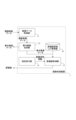
図1は色評価システムの構成を示す図である。色評価システムは、画像処理装置1、表示装置2、撮像装置3、入力デバイス110から構成される。色評価システムは、撮像装置3を用いて評価対象物体4を撮像して得られる撮像画像データを、画像処理装置1において処理する。色評価システムは、処理の結果として得られる表示画像及び評価値を、入力デバイス110を介したユーザの指示に応じて表示装置2に表示する。本実施形態における評価対象物体4は複数の部品から構成される、例えばプリンタなどの工業製品である。
[First embodiment]
<Configuration of color evaluation system>
FIG. 1 is a diagram showing the configuration of a color evaluation system. The color evaluation system includes an image processing device 1, a
<画像処理装置のハードウェア構成>
図2は画像処理装置1のハードウェア構成を示すブロック図である。画像処理装置1は、CPU101、ROM102、RAM103を備える。また、画像処理装置1は、VC(ビデオカード)104、汎用I/F(インターフェース)105、SATA(シリアルATA)I/F106、NIC(ネットワークインターフェースカード)107を備える。
<Hardware configuration of image processing device>
FIG. 2 is a block diagram showing the hardware configuration of the image processing device 1. As shown in FIG. The image processing device 1 includes a
CPU101は、RAM103をワークメモリとして、ROM102、HDD(ハードディスクドライブ)112などに格納されたOS(オペレーティングシステム)や各種プログラムを実行する。また、CPU101は、システムバス108を介して各構成を制御する。尚、後述するフローチャートによる処理は、ROM102やHDD112などに格納されたプログラムコードがRAM103に展開され、CPU101によって実行される。VC104には、表示装置2が接続される。汎用I/F105には、シリアルバス109を介して、マウスやキーボードなどの入力デバイス110や撮像装置3が接続される。SATAI/F106には、シリアルバス111を介して、HDD112や各種記録メディアの読み書きを行う汎用ドライブ113が接続される。NIC107は、外部装置との間で情報の入力及び出力を行う。CPU101は、HDD112や汎用ドライブ113にマウントされた各種記録メディアを各種データの格納場所として使用する。CPU101は、プログラムによって提供されるUI(ユーザインターフェース)を表示装置2に表示し、入力デバイス110を介して受け付けるユーザ指示などの入力を受信する。
The
<画像処理装置の機能構成>
図3は画像処理装置1の機能構成を示すブロック図である。CPU101は、RAM103をワークメモリとして、ROM102又はHDD112に格納されたプログラムを読み出して実行することによって、図3に示す機能構成として機能する。尚、以下に示す処理の全てがCPU101によって実行される必要はなく、処理の一部または全てがCPU101以外の一つまたは複数の処理回路によって行われるように画像処理装置1が構成されていてもよい。
<Functional configuration of image processing device>
FIG. 3 is a block diagram showing the functional configuration of the image processing device 1. As shown in FIG. The
画像処理装置1は、画像データ取得部11、表示画像生成部12、評価用画像生成部13、指定受付部14、評価値算出部15を有する。画像データ取得部11は、撮像装置3が評価対象物体4を撮像して得られる撮像画像データを取得する。本実施形態における画像データ取得部11は、撮像装置3を制御して評価対象物体4を撮像し、撮像画像データを取得する。尚、HDD112に予め保持されていた撮像画像データを、HDD112から取得してもよい。
The image processing device 1 includes an image
表示画像生成部12は、撮像画像データが表す撮像画像に基づいて、評価対象物体4を実物と同じ印象で表示装置2に表示するための表示画像を表す表示画像データを生成する。具体的には、表示画像生成部12は、撮像画像が各画素に画素値として有する色信号値を、表示装置2の特性に応じた色信号値に変換する。ここで、撮像画像が有する色信号値は撮像装置3に依存した色空間において表現される値であり、本実施形態における撮像装置3に依存した色空間は、R,G,Bそれぞれを軸とした色空間である。以下、撮像画像が有する色信号値を、撮像色信号値(RC,GC,BC)と表現する。また、表示装置2の特性に応じた色信号値は表示装置2に依存した色空間において表現される値であり、本実施形態における表示装置2に依存した色空間は、R,G,Bそれぞれを軸とした色空間である。以下、表示装置2の特性に応じた色信号値を、表示色信号値(RD,GD,BD)と表現する。また、表示画像生成部12は、表示色信号値(RD,GD,BD)を各画素に有する表示画像を表示装置2に表示する表示制御部としても機能する。
The display
評価用画像生成部13は、評価対象物体4の色の評価値を算出するために用いる、評価用画像を表す評価用画像データを生成する。具体的には、評価用画像生成部13は、撮像画像が各画素に有する撮像色信号値(RC,GC,BC)を、デバイス非依存の色信号値に変換する。ここで、デバイス非依存の色信号値は、デバイス非依存の色空間において表現される値であり、本実施形態におけるデバイス非依存の色空間は、X,Y,Zそれぞれを軸とした色空間である。以下、デバイス非依存の色信号値を、デバイス非依存の色信号値(X,Y,Z)と表現する。
The evaluation
指定受付部14は、表示装置2に表示された表示画像においてユーザに指定された評価領域を表す評価領域情報を受け付ける。本実施形態における評価領域情報は、表示画像における評価領域の座標(x,y)である。ここで、表示画像においてユーザに指定される領域は、評価対象物体4に対応する領域の少なくとも一部と、評価対象物体4と色を比較したい領域と、の2か所である。本実施形態において指定される2か所の領域はそれぞれ複数の画素を含む領域であるが、指定される領域は1画素であってもよい。尚、評価対象物体4と色を比較したい領域も、評価対象物体4に対応する領域の一部であってもよい。この場合は、評価対象物体4において、部品間の色差など、異なる2か所を比較して色を評価することができる。
The
評価値算出部15は、評価用画像生成部13から入力された評価用画像データと、指定受付部14から入力された評価領域情報と、に基づいて、色の評価値を算出する。具体的には、評価値算出部15は、2つの評価領域それぞれにおいて、デバイス非依存の色信号値(X,Y,Z)の平均値を算出し、算出した平均値を色の評価値に変換する。また、評価値算出部15は、算出した色の評価値を表示画像と併せて表示装置2に表示する表示制御部としても機能する。
The evaluation
<画像処理装置が実行する処理>
図4は画像処理装置1が実行する処理を示すフローチャートである。以下、各ステップ(工程)は符号の前にSをつけて表す。
<Processing executed by the image processing device>
FIG. 4 is a flowchart showing the processing executed by the image processing device 1. Hereinafter, each step (process) is represented by adding S in front of the code.
S41において、画像データ取得部11は、撮像装置3の撮像によって得られる撮像画像データを取得する。S42において、表示画像生成部12は、撮像画像が有する撮像色信号値(RC,GC,BC)を色変換ルックアップテーブルを用いて表示色信号値(RD,GD,BD)に変換することにより、表示画像データを生成する。ここで用いる色変換ルックアップテーブル(以下、色変換LUTと表現する)は、撮像色信号値(RC,GC,BC)と表示色信号値(RD,GD,BD)との対応関係を保持する色変換LUTAである。表示画像生成部12は、予め作成された色変換LUTAをHDD112等の記憶装置から取得して色変換に用いる。色変換LUTAを作成する処理の詳細は後述する。
In S41, the image
S43において、評価用画像生成部13は、撮像画像が有する撮像色信号値(RC,GC,BC)を色変換LUTBを用いてデバイス非依存の色信号値(X,Y,Z)に変換することにより、評価用画像データを生成する。ここで用いる色変換LUTBは、撮像色信号値(RC,GC,BC)とデバイス非依存の色信号値(X,Y,Z)との対応関係を保持する。評価用画像生成部13は、予め作成された色変換LUTBをHDD112等の記憶装置から取得して色変換に用いる。色変換LUTBを作成する処理の詳細は後述する。
In S43, the evaluation
S44において、表示画像生成部12は、表示装置2に表示画像を表示する。S45において、指定受付部14は、表示装置2に表示された表示画像においてユーザに指定された評価領域を表す評価領域情報を受け付ける。S46において、評価値算出部15は、評価用画像データと評価領域情報とに基づいて色の評価値を算出し、算出した評価値を表示装置2に表示する。評価値の算出及び表示に関する処理の詳細は後述する。
In S44, the display
<色変換LUTAを作成する処理>
ここでは、色変換LUTAを作成する処理の詳細について説明する。図5は色変換LUTAを作成する処理を示すフローチャートである。
<Processing to create color conversion LUT A >
Here, details of the process for creating color conversion LUT A will be explained. FIG. 5 is a flowchart showing the process of creating color conversion LUT A.
S51において、撮像色信号値(RC,GC,BC)とデバイス非依存の色信号値(X,Y,Z)との対応関係を表す関係式が作成される。関係式を作成する際には、例えば図6に示すような、複数のカラーパッチを含むカラーチャートを使用する。まず、複数のカラーパッチそれぞれを撮像装置3を用いて撮像して撮像色信号値(RC,GC,BC)を取得する。各カラーパッチ内の撮像色信号値(RC,GC,BC)が平均されることにより、カラーパッチそれぞれに1つずつ撮像色信号値(RC,GC,BC)が得られる。取得した撮像色信号値(RC,GC,BC)それぞれを、式(1),式(2),式(3),式(4),式(5)を用いて、L*a*b*値(L* 1,a* 1,b* 1)に変換する。ここで、基準白色の色信号値を(XW,YW,ZW)とする。尚、L*a*b*値は、デバイス非依存の色信号値であり、L*,a*,b*それぞれを軸とした色空間において表現される値である。 In S51, a relational expression representing the correspondence between the captured color signal values (R C , G C , B C ) and the device-independent color signal values (X, Y, Z) is created. When creating a relational expression, a color chart including a plurality of color patches as shown in FIG. 6, for example, is used. First, each of a plurality of color patches is imaged using the imaging device 3 to obtain imaged color signal values (R C , G C , B C ). By averaging the captured color signal values (R C , G C , B C ) in each color patch, one captured color signal value (R C , G C , B C ) is obtained for each color patch. . Each of the acquired imaged color signal values (R C , G C , B C ) is calculated as L * a using Equation (1), Equation (2), Equation (3), Equation (4), and Equation (5). Convert to * b * value (L * 1 , a * 1 , b * 1 ). Here, the color signal values of the reference white are (X W , Y W , Z W ). Note that the L * a * b * value is a device-independent color signal value, and is a value expressed in a color space with L * , a * , and b * as axes.

次に、複数のカラーパッチそれぞれを測色計を用いて測定することによりデバイス非依存の色信号値(X,Y,Z)を取得する。各カラーパッチ内のデバイス非依存の色信号値(X,Y,Z)が平均されることにより、カラーパッチそれぞれに1つずつデバイス非依存の色信号値(X,Y,Z)が得られる。取得したデバイス非依存の色信号値(X,Y,Z)それぞれを、式(2),式(3),式(4),式(5)を用いて、L*a*b*値(L* 2,a* 2,b* 2)に変換する。 Next, device-independent color signal values (X, Y, Z) are obtained by measuring each of the plurality of color patches using a colorimeter. The device-independent color signal values (X, Y, Z) in each color patch are averaged to obtain one device-independent color signal value (X, Y, Z) for each color patch. . Each of the obtained device-independent color signal values (X, Y, Z) is calculated as L * a * b * value ( L * 2 , a * 2 , b * 2 ).
式(6)に示す色差ΔEが0に近づくように、式(1)のマトリクスの係数(α0~α8)を最小二乗法により求める。マトリクスの係数(α0~α8)を求めることにより、撮像色信号値(RC,GC,BC)とデバイス非依存の色信号値(X,Y,Z)との対応関係を表す関係式である式(1)が得られる。 The coefficients (α0 to α8) of the matrix in equation (1) are determined by the least squares method so that the color difference ΔE shown in equation (6) approaches 0. By determining the matrix coefficients (α0 to α8), a relational expression expressing the correspondence between the imaging color signal values (R C , G C , B C ) and the device-independent color signal values (X, Y, Z) can be obtained. Equation (1) is obtained.

S52において、表示色信号値(RD,GD,BD)とデバイス非依存の色信号値(X,Y,Z)との対応関係を保持する色変換LUTDが作成される。まず、表示装置2に、表示色信号値(RD,GD,BD)を、(0,0,0)から(255,255,255)まで、R,G,Bそれぞれを32ずつ異ならせた、合計729通りのカラーパッチを含むカラーチャートを表示する。次に、表示されたカラーパッチそれぞれを測色計を用いて測定することによりデバイス非依存の色信号値(X,Y,Z)を取得する。これにより、各カラーパッチについて、表示色信号値(RD,GD,BD)とデバイス非依存の色信号値(X,Y,Z)との対応関係が得られるため、この対応関係を用いて色変換LUTDを生成する。
In S52, a color conversion LUT D is created that maintains the correspondence between display color signal values (R D , G D , B D ) and device-independent color signal values (X, Y, Z). First, display color signal values (R D , G D , B D ) are set on the
S53において、ガマットマッピングにより、撮像色信号値(RC,GC,BC)と表示色信号値(RD,GD,BD)との対応関係を保持する色変換LUTAが作成される。まず、S51において得られた関係式を用いて、撮像色信号値(RC,GC,BC)とデバイス非依存の色信号値(X,Y,Z)との対応関係を保持する色変換LUTCを作成する。色変換LUTCは、撮像色信号値(RC,GC,BC)を、(0,0,0)から(255,255,255)まで、R,G,Bそれぞれを32ずつ異ならせて729通りの対応関係を取得することにより作成できる。次に、作成した色変換LUTCと色変換LUTDとを用いて、公知のガマットマッピングにより、撮像色信号値(RC,GC,BC)を表示色信号値(RD,GD,BD)に変換する。この変換により、撮像色信号値(RC,GC,BC)と表示色信号値(RD,GD,BD)との対応関係が得られるため、色変換LUTAを作成することができる。尚、ここで行うガマットマッピングは、評価対象物体4を実物と同じ印象で表示装置2に表示するために、知覚的(Perceptual)のガマットマッピングが望ましい。
In S53, a color conversion LUT A is created by gamut mapping to maintain the correspondence between the imaging color signal values (R C , G C , B C ) and the display color signal values (R D , G D , B D ). Ru. First, using the relational expression obtained in S51, a color is determined that maintains the correspondence between the imaging color signal values (R C , G C , B C ) and the device-independent color signal values (X, Y, Z). Create conversion LUT C. Color conversion LUT C changes the imaging color signal values (R C , G C , B C ) from (0, 0, 0) to (255, 255, 255) by 32 for each of R, G, and B. It can be created by acquiring 729 types of correspondence relationships. Next, using the created color conversion LUT C and color conversion LUT D , the imaged color signal values (R C , G C , B C ) are displayed as the display color signal values (R D , G D ) by known gamut mapping. , B D ). Through this conversion, a correspondence relationship between the captured color signal values (R C , G C , B C ) and the display color signal values (R D , G D , B D ) can be obtained, so a color conversion LUT A can be created. I can do it. Note that the gamut mapping performed here is preferably perceptual gamut mapping in order to display the evaluation target object 4 on the
<色変換LUTBを作成する処理>
ここでは、色変換LUTBを作成する処理の詳細について説明する。図7は色変換LUTBを作成する処理を示すフローチャートである。
<Processing to create color conversion LUT B >
Here, details of the process for creating color conversion LUT B will be explained. FIG. 7 is a flowchart showing the process of creating color conversion LUT B.
S71において、撮像色信号値(RC,GC,BC)とデバイス非依存の色信号値(X,Y,Z)との対応関係を表す関係式が作成される。S71における処理は、S51と同じ処理であるため説明を省略する。尚、予めS51において関係式を作成した場合は、S71における処理は行わなくてもよい。ここで作成される関係式には、色の評価値を高精度に算出するために、3×3のマトリクスなど、線形性の高いマトリクスを用いることが望ましい。線形性の高いマトリクスを用いることにより、評価対象物体4の輝度に対して線形な評価値を算出することができる。 In S71, a relational expression representing the correspondence between the captured color signal values (R C , G C , B C ) and the device-independent color signal values (X, Y, Z) is created. The process in S71 is the same process as S51, so the explanation will be omitted. Note that if the relational expression is created in advance in S51, the process in S71 may not be performed. For the relational expression created here, it is desirable to use a matrix with high linearity, such as a 3×3 matrix, in order to calculate the color evaluation value with high precision. By using a matrix with high linearity, it is possible to calculate a linear evaluation value for the luminance of the evaluation target object 4.
S72において、S71において得られた関係式を用いて、撮像色信号値(RC,GC,BC)とデバイス非依存の色信号値(X,Y,Z)との対応関係を保持する色変換LUTBを作成する。S72における処理は、S53における色変換LUTCを作成する処理と同じ処理であるため説明を省略する。尚、予めS53において色変換LUTCを作成した場合は、S72における処理は行わずに、色変換LUTCを色変換LUTBとして用いることができる。 In S72, the relational expression obtained in S71 is used to maintain the correspondence between the imaging color signal values (R C , G C , B C ) and the device-independent color signal values (X, Y, Z). Create color conversion LUT B. The process in S72 is the same process as the process to create the color conversion LUT C in S53, so a description thereof will be omitted. Note that if the color conversion LUT C is created in advance in S53, the color conversion LUT C can be used as the color conversion LUT B without performing the process in S72.
<評価対象物体に対する色信号値の線形性>
図8に、評価対象物体4の輝度に対する、表示色信号値(RD,GD,BD)及びデバイス非依存の色信号値(X,Y,Z)の線形性について示す。表示画像の表示色信号値(RD,GD,BD)は、表示装置2の表示可能な輝度範囲により、評価対象物体4の輝度に対して線形性を保つことができない。このため、図8(a)のように、評価対象物体4の高輝度領域に対応する色信号値に対して非線形圧縮を行う必要がある。S53においてガマットマッピングを行うのはそのためである。
<Linearness of color signal value for evaluation target object>
FIG. 8 shows the linearity of display color signal values (R D , G D , B D ) and device-independent color signal values (X, Y, Z) with respect to the luminance of the evaluation target object 4. The display color signal values (R D , G D , B D ) of the display image cannot maintain linearity with respect to the luminance of the evaluation target object 4 due to the displayable luminance range of the
一方で、評価用画像のデバイス非依存の色信号値(X,Y,Z)は、S71において評価対象物体4の輝度に対して線形性が高くなるように関係式を作成するため、図8(b)のように評価対象物体4の輝度に対して線形性を保つことができる。 On the other hand, for the device-independent color signal values (X, Y, Z) of the evaluation image, in order to create a relational expression so that linearity is high with respect to the luminance of the evaluation target object 4 in S71, FIG. As shown in (b), linearity can be maintained with respect to the luminance of the evaluation target object 4.
このように、撮像画像に対する、表示と評価それぞれに適した変換により、表示画像と評価用画像とを別々に生成することにより、ユーザは、評価対象物体4を実物と同じ印象で確認しながら、指定した領域の高精度な評価値に応じて色の評価を行うことができる。 In this way, by separately generating the display image and the evaluation image by converting the captured image suitable for display and evaluation, the user can check the evaluation target object 4 with the same impression as the real thing. Color evaluation can be performed according to highly accurate evaluation values of specified areas.
<評価値を算出する処理>
ここでは、S46における、評価値を算出する処理の詳細について説明する。図9は評価値を算出する処理を示すフローチャートである。
<Processing to calculate evaluation value>
Here, details of the process of calculating the evaluation value in S46 will be described. FIG. 9 is a flowchart showing the process of calculating an evaluation value.
S91において、評価値算出部15は、評価用画像において評価領域情報が表す領域に対応するデバイス非依存の色信号値(X,Y,Z)を取得する。S92において、評価値算出部15は、評価領域それぞれにおいて、デバイス非依存の色信号値(X,Y,Z)の平均値を算出する。これにより、各評価領域に対して1つのデバイス非依存の色信号値(X,Y,Z)が得られる。
In S91, the evaluation
S93において、評価値算出部15は、各評価領域について、デバイス非依存の色信号値(X,Y,Z)をL*a*b*値に変換する。変換には、上述した式(2)~式(5)を用いる。基準白色の色信号値(XW,YW,ZW)は、表示画像においてユーザが基準白色点を指定することにより得られる。S94において、評価値算出部15は、デバイス非依存の色信号値(X,Y,Z)と、L*a*b*値と、を評価値として表示装置2に表示する。
In S93, the evaluation
表示画像と評価値との表示例を図10に示す。図10において、ウィンドウ1001には、表示画像1002が表示されている。また、S93において算出した評価値が数値として数値表示領域1003として表示されるとともに、グラフ1004にプロットされた点1009及び点1010としても表示される。ユーザは、入力デバイス110で操作可能なポインタ1005を用いて、白色点1006,第1評価領域1007,第2評価領域1008を指定することができる。第1評価領域1007の評価値が点1009に対応する場合、同じ色(例えば黄色)で枠線を描画する。また、第1評価領域1007の評価値に対応する数値表示領域1003における数値の背景も同じ色(黄色)で描画する。
A display example of a display image and evaluation value is shown in FIG. In FIG. 10, a
第2評価領域1008の枠線,点1010の枠線,第2評価領域1008の評価値に対応する数値表示領域1003における数値の背景を同じ色(例えば青色)で描画する。また、白色点1006の枠線と数値表示領域1003における基準白色の色信号値の背景を同じ色(例えば赤色)で描画する。このように、評価領域と対応する評価値とを同一色で描画することにより、評価領域と評価値との対応関係を容易に確認することができる。
The frame line of the
<第1実施形態の効果>
以上説明したように、本実施形態における画像処理装置1は、物体を撮像して得られる撮像画像データを取得する。撮像画像データが表す撮像画像に含まれる各画素の色信号値を表示手段の特性に応じた色信号値に変換することによって、表示画像データを生成する。表示画像データが表す表示画像においてユーザに指定された複数の領域に対応する色の評価値を算出する。複数の領域と、評価値と、を対応付けて表示手段に表示する。これにより、物体の撮像画像を基に、ユーザの領域指定に対してリアルタイムに実物の色を評価することができる。
<Effects of the first embodiment>
As explained above, the image processing device 1 in this embodiment acquires captured image data obtained by capturing an image of an object. Display image data is generated by converting the color signal value of each pixel included in the captured image represented by the captured image data into a color signal value corresponding to the characteristics of the display means. Calculates evaluation values of colors corresponding to a plurality of areas designated by the user in a display image represented by display image data. A plurality of areas and evaluation values are displayed in association with each other on a display means. Thereby, the color of the actual object can be evaluated in real time based on the captured image of the object in response to the region specified by the user.
<変形例>
図10においては、枠線や背景の色で評価領域の区別を行ったが、別の表示方法で対応関係をわかりやすくしてもよい。例えば、図11に示すように、指定した点の周囲に四角形,三角形,星などの記号を配置してもよい。また、図12に示すように、指定した点を特定する枠の形状を四角形,三角形,星の形などの形にしてもよい。
<Modified example>
In FIG. 10, the evaluation areas are distinguished by the color of the frame line or background, but the correspondence relationship may be made easier to understand by using another display method. For example, as shown in FIG. 11, symbols such as rectangles, triangles, and stars may be placed around the designated points. Further, as shown in FIG. 12, the shape of the frame specifying the specified point may be a rectangle, a triangle, a star, or the like.
また、第1実施形態においては、評価値をデバイス非依存の色信号値(X,Y,Z)及びL*a*b*値(L*,a*,b*)として表示したが、どちらか一方を評価値として表示してもよい。また、評価領域間の色差を評価値をとして表示してもよい。この場合の色差は、例えば式(6)を用いて算出することができる。また、評価値は彩度差や明度差などであってもよい。 Furthermore, in the first embodiment, the evaluation values are displayed as device-independent color signal values (X, Y, Z) and L * a * b * values (L * , a * , b * ); Either one may be displayed as the evaluation value. Furthermore, the color difference between the evaluation areas may be displayed as the evaluation value. The color difference in this case can be calculated using equation (6), for example. Furthermore, the evaluation value may be a saturation difference, a brightness difference, or the like.
また、第1実施形態においては、ユーザにより指定された2か所の評価値を表示したが、指定される評価領域は複数であれば3か所以上であってもよい。 Further, in the first embodiment, the evaluation values of two locations designated by the user are displayed, but as long as the number of evaluation regions designated is plural, three or more locations may be displayed.
また、第1実施形態においては、表示画像生成部12と評価値算出部15とが表示の制御を行ったが、図16のように、画像処理装置1は表示画像生成部12と評価値算出部15とは別に表示制御部18を有していてもよい。この場合は、表示制御部18が表示画像及び評価値の表示を制御する。
Further, in the first embodiment, the display
[第2実施形態]
第1実施形態においては、撮像画像データを基に表示画像データと評価用画像データとを別々に生成した。本実施形態においては、撮像画像データを基に表示画像データを生成し、表示画像データを基に評価値を取得する。尚、本実施形態における画像処理装置1のハードウェア構成は第1実施形態のものと同様であるため、説明を省略する。以下において、本実施形態と第1実施形態とで異なる部分を主に説明する。尚、同一の構成については、同じ符号を付して説明する。
[Second embodiment]
In the first embodiment, display image data and evaluation image data are generated separately based on captured image data. In this embodiment, display image data is generated based on captured image data, and evaluation values are obtained based on the display image data. Note that the hardware configuration of the image processing device 1 in this embodiment is the same as that in the first embodiment, so a description thereof will be omitted. Below, the differences between this embodiment and the first embodiment will be mainly explained. Note that the same components will be described with the same reference numerals.
<画像処理装置の機能構成>
図13は画像処理装置1の機能構成を示すブロック図である。CPU101は、RAM103をワークメモリとして、ROM102又はHDD112に格納されたプログラムを読み出して実行することによって、図13に示す機能構成として機能する。尚、以下に示す処理の全てがCPU101によって実行される必要はなく、処理の一部または全てがCPU101以外の一つまたは複数の処理回路によって行われるように画像処理装置1が構成されていてもよい。
<Functional configuration of image processing device>
FIG. 13 is a block diagram showing the functional configuration of the image processing device 1. As shown in FIG. The
画像処理装置1は、画像データ取得部11、表示画像生成部12、指定受付部14、評価値変換LUT保持部16、評価値取得部17を有する。評価値変換LUT保持部16は、表示画像の表示色信号値(RD,GD,BD)と評価値との対応関係を保持する評価値変換LUTを保持する。評価値取得部17は、評価領域情報と、表示画像データと、評価値変換LUTと、に基づいて色の評価値を取得し、取得した評価値を表示装置2に表示する。
The image processing device 1 includes an image
<画像処理装置1が実行する処理>
図14は画像処理装置1が実行する処理を示すフローチャートである。S1401において、画像データ取得部11は、撮像装置3の撮像によって得られる撮像画像データを取得する。S1402において、表示画像生成部12は、撮像画像が有する撮像色信号値(RC,GC,BC)を色変換LUTAを用いて表示色信号値(RD,GD,BD)に変換することにより、表示画像データを生成する。
<Processing executed by image processing device 1>
FIG. 14 is a flowchart showing the processing executed by the image processing device 1. In S1401, the image
S1403において、表示画像生成部12は、表示装置2に表示画像を表示する。S1404において、指定受付部14は、表示装置2に表示された表示画像においてユーザに指定された評価領域を表す評価領域情報を受け付ける。S1405において、評価値取得部17は、評価領域情報と、表示画像データと、評価値変換LUTと、に基づいて色の評価値を取得し、取得した評価値を表示装置2に表示する。評価値の取得及び表示に関する処理の詳細は後述する。
In S1403, the display
<評価値を取得する処理>
ここでは、S1405における、評価値を取得する処理の詳細について説明する。図15は評価値を取得する処理を示すフローチャートである。
<Processing to obtain evaluation value>
Here, details of the process of acquiring the evaluation value in S1405 will be described. FIG. 15 is a flowchart showing the process of acquiring evaluation values.
S1501において、評価値取得部17は、表示画像において評価領域情報が表す領域に対応する表示色信号値(RD,GD,BD)を取得する。S1502において、評価値取得部17は、評価領域それぞれにおいて、表示色信号値(RD,GD,BD)の平均値を算出する。これにより、各評価領域に対して1つの表示色信号値(RD,GD,BD)が得られる。
In S1501, the evaluation
S1503において、評価値取得部17は、各評価領域について、表示色信号値(RD,GD,BD)を評価値変換LUTを用いて評価値に変換する。本実施形態においては、表示色信号値(RD,GD,BD)をデバイス非依存の色信号値(X,Y,Z)に変換する。ここでは、上述した色変換LUTDを評価値変換LUTとして用いる。S1504において、評価値取得部17は、デバイス非依存の色信号値(X,Y,Z)をL*a*b*値に変換する。変換には、上述した式(2)~式(5)を用いる。基準白色の色信号値(XW,YW,ZW)は、表示画像においてユーザが基準白色点を指定することにより得られる。S1505において、評価値取得部17は、デバイス非依存の色信号値(X,Y,Z)と、L*a*b*値と、を評価値として表示装置2に表示する。
In S1503, the evaluation
<第2実施形態の効果>
以上説明したように、本実施形態における画像処理装置1は、撮像画像データを基に表示画像データを生成し、表示画像データを基に評価値を取得した。これにより、物体の撮像画像を基に、ユーザの領域指定に対してリアルタイムに実物の色を評価することができる。
<Effects of the second embodiment>
As described above, the image processing device 1 in this embodiment generates display image data based on captured image data, and acquires an evaluation value based on the display image data. Thereby, the color of the actual object can be evaluated in real time based on the captured image of the object in response to the region specified by the user.
[その他の実施形態]
本発明は、上述の実施形態の1以上の機能を実現するプログラムを、ネットワーク又は記憶媒体を介してシステム又は装置に供給し、そのシステム又は装置のコンピュータにおける1つ以上のプロセッサーがプログラムを読出し実行する処理でも実現可能である。また、1以上の機能を実現する回路(例えば、ASIC)によっても実現可能である。
[Other embodiments]
The present invention provides a system or device with a program that implements one or more of the functions of the embodiments described above via a network or a storage medium, and one or more processors in the computer of the system or device reads and executes the program. This can also be achieved by processing. It can also be realized by a circuit (for example, ASIC) that realizes one or more functions.
1 画像処理装置
11 画像データ取得部
12 表示画像生成部
15 評価値算出部
1
Claims (18)
前記撮像画像データが表す撮像画像に含まれる各画素の第1色信号値を前記物体の輝度に対して非線形な色信号値を得るための第1ルックアップテーブルを用いて表示手段の特性に応じた第2色信号値に変換することによって、表示画像データを生成する生成手段と、
前記表示画像データが表す表示画像においてユーザに指定された複数の領域に対応する色の評価値を、前記物体の輝度に対して線形な評価値を得るための第2ルックアップテーブルを用いて算出する算出手段と、
前記複数の領域と、前記評価値と、を対応付けて前記表示手段に表示する表示制御手段と、
を有することを特徴とする画像処理装置。 acquisition means for acquiring captured image data obtained by imaging an object;
The first color signal value of each pixel included in the captured image represented by the captured image data is determined according to the characteristics of the display means using a first lookup table for obtaining a nonlinear color signal value with respect to the luminance of the object. generating means for generating display image data by converting the second color signal value into a second color signal value;
Calculate evaluation values of colors corresponding to a plurality of areas specified by the user in the display image represented by the display image data using a second lookup table for obtaining evaluation values linear with respect to the brightness of the object. a calculation means to
display control means for displaying the plurality of regions and the evaluation value in correspondence on the display means;
An image processing device comprising:
前記表示制御手段は、前記第1評価値と前記第1領域とを第1色で表示し、前記第2評価値と前記第2領域とを前記第1色とは異なる第2色で表示することを特徴とする請求項1に記載の画像処理装置。 The plurality of regions include a first region corresponding to a first evaluation value and a second region corresponding to a second evaluation value,
The display control means displays the first evaluation value and the first area in a first color, and displays the second evaluation value and the second area in a second color different from the first color. The image processing device according to claim 1, characterized in that:
前記表示制御手段は、前記第1評価値と前記第1領域との周囲に第1記号を表示し、前記第2評価値と前記第2領域との周囲に前記第1記号とは異なる第2記号を表示することを特徴とする請求項1に記載の画像処理装置。 The plurality of regions include a first region corresponding to a first evaluation value and a second region corresponding to a second evaluation value,
The display control means displays a first symbol around the first evaluation value and the first area, and displays a second symbol different from the first symbol around the second evaluation value and the second area. The image processing device according to claim 1, wherein the image processing device displays a symbol.
前記表示制御手段は、前記第1評価値と前記第1領域とを特定する枠の形を第1形状として表示し、前記第2評価値と前記第2領域とを特定する枠の形を前記第1形状とは異なる第2形状として表示することを特徴とする請求項1に記載の画像処理装置。 The plurality of regions include a first region corresponding to a first evaluation value and a second region corresponding to a second evaluation value,
The display control means displays the shape of a frame that specifies the first evaluation value and the first region as a first shape, and displays the shape of a frame that specifies the second evaluation value and the second region as the first shape. The image processing device according to claim 1, wherein the image processing device displays the image as a second shape different from the first shape.
前記評価値は、前記複数の部品間の色差であることを特徴とする請求項8に記載の画像処理装置。 The object is an industrial product consisting of multiple parts,
The image processing apparatus according to claim 8, wherein the evaluation value is a color difference between the plurality of parts.
前記算出手段は、前記評価用画像データに基づいて、前記評価値を算出することを特徴とする請求項1乃至請求項9のいずれか一項に記載の画像処理装置。 further comprising a second generation means for generating evaluation image data by converting a first color signal value of each pixel included in the captured image represented by the captured image into a device-independent third color signal value,
The image processing apparatus according to any one of claims 1 to 9, wherein the calculation means calculates the evaluation value based on the evaluation image data.
前記第3色信号値は前記物体の輝度に対して線形な値であることを特徴とする請求項10に記載の画像処理装置。 The second color signal value is a value that is nonlinear with respect to the brightness of the object,
The image processing apparatus according to claim 10, wherein the third color signal value is a value linear with respect to the brightness of the object.
前記算出手段は、前記領域情報に基づいて、前記評価値を算出することを特徴とする請求項1乃至請求項11のいずれか一項に記載の画像処理装置。 further comprising reception means for accepting area information representing the plurality of areas in response to an instruction from the user;
The image processing apparatus according to any one of claims 1 to 11, wherein the calculation means calculates the evaluation value based on the area information.
前記撮像画像データが表す撮像画像に含まれる各画素の第1色信号値を前記物体の輝度に対して非線形な色信号値を得るための第1ルックアップテーブルを用いて表示手段の特性に応じた第2色信号値に変換することによって、表示画像データを生成する生成ステップと、
前記表示画像データが表す表示画像においてユーザに指定された複数の領域に対応する色の評価値を、前記物体の輝度に対して線形な評価値を得るための第2ルックアップテーブルを用いて算出する算出ステップと、
前記複数の領域と、前記評価値と、を対応付けて前記表示手段に表示する表示制御ステップと、
を有することを特徴とする画像処理方法。 an acquisition step of acquiring captured image data obtained by imaging the object;
The first color signal value of each pixel included in the captured image represented by the captured image data is determined according to the characteristics of the display means using a first lookup table for obtaining a nonlinear color signal value with respect to the luminance of the object. a generation step of generating display image data by converting the second color signal value into a second color signal value;
Calculate evaluation values of colors corresponding to a plurality of areas specified by the user in the display image represented by the display image data using a second lookup table for obtaining evaluation values linear with respect to the brightness of the object. a calculation step,
a display control step of displaying the plurality of regions and the evaluation value in correspondence on the display means;
An image processing method comprising:
Priority Applications (1)
| Application Number | Priority Date | Filing Date | Title |
|---|---|---|---|
| JP2019197999A JP7366689B2 (en) | 2019-10-30 | 2019-10-30 | Image processing device, image processing method and program |
Applications Claiming Priority (1)
| Application Number | Priority Date | Filing Date | Title |
|---|---|---|---|
| JP2019197999A JP7366689B2 (en) | 2019-10-30 | 2019-10-30 | Image processing device, image processing method and program |
Publications (2)
| Publication Number | Publication Date |
|---|---|
| JP2021072541A JP2021072541A (en) | 2021-05-06 |
| JP7366689B2 true JP7366689B2 (en) | 2023-10-23 |
Family
ID=75713754
Family Applications (1)
| Application Number | Title | Priority Date | Filing Date |
|---|---|---|---|
| JP2019197999A Active JP7366689B2 (en) | 2019-10-30 | 2019-10-30 | Image processing device, image processing method and program |
Country Status (1)
| Country | Link |
|---|---|
| JP (1) | JP7366689B2 (en) |
Citations (3)
| Publication number | Priority date | Publication date | Assignee | Title |
|---|---|---|---|---|
| JP2016006416A (en) | 2014-05-26 | 2016-01-14 | 有限会社パパラボ | Coloring evaluation device and coloring evaluation method |
| JP2017056245A (en) | 2012-02-20 | 2017-03-23 | キヤノン株式会社 | Image processing device and image processing method |
| JP2017229064A (en) | 2016-06-21 | 2017-12-28 | キヤノン株式会社 | Information processing apparatus, information processing method, and program |
-
2019
- 2019-10-30 JP JP2019197999A patent/JP7366689B2/en active Active
Patent Citations (3)
| Publication number | Priority date | Publication date | Assignee | Title |
|---|---|---|---|---|
| JP2017056245A (en) | 2012-02-20 | 2017-03-23 | キヤノン株式会社 | Image processing device and image processing method |
| JP2016006416A (en) | 2014-05-26 | 2016-01-14 | 有限会社パパラボ | Coloring evaluation device and coloring evaluation method |
| JP2017229064A (en) | 2016-06-21 | 2017-12-28 | キヤノン株式会社 | Information processing apparatus, information processing method, and program |
Also Published As
| Publication number | Publication date |
|---|---|
| JP2021072541A (en) | 2021-05-06 |
Similar Documents
| Publication | Publication Date | Title |
|---|---|---|
| US20140232923A1 (en) | Device independent color differences | |
| CN107408373B (en) | Stable color rendering manager | |
| EP2286597B1 (en) | Video monitoring device providing parametric signal curve display features and related methods | |
| CN106716491B (en) | Image color calibration with multiple color scales | |
| JP7366689B2 (en) | Image processing device, image processing method and program | |
| JP2019205104A (en) | Information processing apparatus, information processing method, and program | |
| JP7154786B2 (en) | Image processing device, image processing method and program | |
| JP2019205103A (en) | Information processing apparatus, information processing method, and program | |
| EP2284799B1 (en) | The method for colour picking over an image data to be used in graphical user interface | |
| US20240121380A1 (en) | Resolution measurement method, resolution measurement system, and program | |
| US20210225306A1 (en) | Display device and control method of display device | |
| JP2020088709A (en) | Image processing apparatus, image processing method and program | |
| JP7427423B2 (en) | Image processing device, image processing method and program | |
| JP6401632B2 (en) | Color gamut coverage information generation apparatus and color gamut coverage information generation method | |
| JP7329964B2 (en) | Image processing device, image processing method and program | |
| JP2015211470A (en) | Device and method | |
| US20220012521A1 (en) | System for luminance qualified chromaticity | |
| JP2007190208A (en) | Comparative diagnostic reading support system | |
| JP7106318B2 (en) | Image processing device, image processing method and program | |
| KR101074184B1 (en) | Method for transforming color images to grayscale and recorded medium having program performing the same | |
| JP2020167563A (en) | Image processing device, image processing method and program | |
| US8861023B2 (en) | Generating an unambiguous definition of designer intended colors in a document creation application | |
| JP2010145097A (en) | Color unevenness inspection method, and inspection image data generation apparatus | |
| JP2021036648A (en) | Information processing device, information processing method, and program | |
| JP2010081051A (en) | Method of converting color, color conversion device, and color conversion program |
Legal Events
| Date | Code | Title | Description |
|---|---|---|---|
| A621 | Written request for application examination |
Free format text: JAPANESE INTERMEDIATE CODE: A621 Effective date: 20221007 |
|
| A977 | Report on retrieval |
Free format text: JAPANESE INTERMEDIATE CODE: A971007 Effective date: 20230627 |
|
| A131 | Notification of reasons for refusal |
Free format text: JAPANESE INTERMEDIATE CODE: A131 Effective date: 20230704 |
|
| A521 | Request for written amendment filed |
Free format text: JAPANESE INTERMEDIATE CODE: A523 Effective date: 20230901 |
|
| TRDD | Decision of grant or rejection written | ||
| A01 | Written decision to grant a patent or to grant a registration (utility model) |
Free format text: JAPANESE INTERMEDIATE CODE: A01 Effective date: 20230912 |
|
| A61 | First payment of annual fees (during grant procedure) |
Free format text: JAPANESE INTERMEDIATE CODE: A61 Effective date: 20231011 |
|
| R151 | Written notification of patent or utility model registration |
Ref document number: 7366689 Country of ref document: JP Free format text: JAPANESE INTERMEDIATE CODE: R151 |