JP7363380B2 - Display system control method and control device - Google Patents
Display system control method and control device Download PDFInfo
- Publication number
- JP7363380B2 JP7363380B2 JP2019198463A JP2019198463A JP7363380B2 JP 7363380 B2 JP7363380 B2 JP 7363380B2 JP 2019198463 A JP2019198463 A JP 2019198463A JP 2019198463 A JP2019198463 A JP 2019198463A JP 7363380 B2 JP7363380 B2 JP 7363380B2
- Authority
- JP
- Japan
- Prior art keywords
- image
- brightness
- projector
- images
- projectors
- Prior art date
- Legal status (The legal status is an assumption and is not a legal conclusion. Google has not performed a legal analysis and makes no representation as to the accuracy of the status listed.)
- Active
Links
Images


Classifications
-
- H—ELECTRICITY
- H04—ELECTRIC COMMUNICATION TECHNIQUE
- H04N—PICTORIAL COMMUNICATION, e.g. TELEVISION
- H04N9/00—Details of colour television systems
- H04N9/12—Picture reproducers
- H04N9/31—Projection devices for colour picture display, e.g. using electronic spatial light modulators [ESLM]
- H04N9/3179—Video signal processing therefor
- H04N9/3182—Colour adjustment, e.g. white balance, shading or gamut
-
- H—ELECTRICITY
- H04—ELECTRIC COMMUNICATION TECHNIQUE
- H04N—PICTORIAL COMMUNICATION, e.g. TELEVISION
- H04N9/00—Details of colour television systems
- H04N9/12—Picture reproducers
- H04N9/31—Projection devices for colour picture display, e.g. using electronic spatial light modulators [ESLM]
- H04N9/3141—Constructional details thereof
- H04N9/3147—Multi-projection systems
-
- G—PHYSICS
- G03—PHOTOGRAPHY; CINEMATOGRAPHY; ANALOGOUS TECHNIQUES USING WAVES OTHER THAN OPTICAL WAVES; ELECTROGRAPHY; HOLOGRAPHY
- G03B—APPARATUS OR ARRANGEMENTS FOR TAKING PHOTOGRAPHS OR FOR PROJECTING OR VIEWING THEM; APPARATUS OR ARRANGEMENTS EMPLOYING ANALOGOUS TECHNIQUES USING WAVES OTHER THAN OPTICAL WAVES; ACCESSORIES THEREFOR
- G03B21/00—Projectors or projection-type viewers; Accessories therefor
-
- H—ELECTRICITY
- H04—ELECTRIC COMMUNICATION TECHNIQUE
- H04N—PICTORIAL COMMUNICATION, e.g. TELEVISION
- H04N9/00—Details of colour television systems
- H04N9/12—Picture reproducers
- H04N9/31—Projection devices for colour picture display, e.g. using electronic spatial light modulators [ESLM]
- H04N9/3179—Video signal processing therefor
- H04N9/3185—Geometric adjustment, e.g. keystone or convergence
-
- H—ELECTRICITY
- H04—ELECTRIC COMMUNICATION TECHNIQUE
- H04N—PICTORIAL COMMUNICATION, e.g. TELEVISION
- H04N9/00—Details of colour television systems
- H04N9/12—Picture reproducers
- H04N9/31—Projection devices for colour picture display, e.g. using electronic spatial light modulators [ESLM]
- H04N9/3191—Testing thereof
- H04N9/3194—Testing thereof including sensor feedback
-
- H—ELECTRICITY
- H04—ELECTRIC COMMUNICATION TECHNIQUE
- H04N—PICTORIAL COMMUNICATION, e.g. TELEVISION
- H04N9/00—Details of colour television systems
- H04N9/12—Picture reproducers
- H04N9/31—Projection devices for colour picture display, e.g. using electronic spatial light modulators [ESLM]
- H04N9/3197—Projection devices for colour picture display, e.g. using electronic spatial light modulators [ESLM] using light modulating optical valves
Landscapes
- Engineering & Computer Science (AREA)
- Multimedia (AREA)
- Signal Processing (AREA)
- Physics & Mathematics (AREA)
- General Physics & Mathematics (AREA)
- Geometry (AREA)
- Controls And Circuits For Display Device (AREA)
- Transforming Electric Information Into Light Information (AREA)
- Projection Apparatus (AREA)
- Video Image Reproduction Devices For Color Tv Systems (AREA)
Description
本発明は、表示システムの制御方法および制御装置に関する。 The present invention relates to a display system control method and control device.
特許文献1には、プロジェクター100A~100Dを有するプロジェクションシステムが記載されている。
このプロジェクションシステムは、プロジェクター100Aが投射する画像を、プロジェクター100Bが投射する画像と、第1投射領域において重ねることによって、第1スタック画像を表示する。さらに、このプロジェクションシステムは、プロジェクター100Cが投射する画像を、プロジェクター100Dが投射する画像と、第2投射領域において重ねることによって、第2スタック画像を表示する。そして、第1スタック画像と第2スタック画像とが並べられることによって、タイリング画像が表示される。
Patent Document 1 describes a projection system having projectors 100A to 100D.
This projection system displays a first stacked image by overlapping the image projected by the projector 100A with the image projected by the projector 100B in the first projection area. Furthermore, this projection system displays a second stacked image by overlapping the image projected by the projector 100C with the image projected by the projector 100D in the second projection area. A tiled image is displayed by arranging the first stack image and the second stack image.
特許文献1に記載の技術では、プロジェクター100A~100Dの各々が共通の画像信号に基づいて画像を投射する状況において各画像の明るさが相互に異なる場合、タイリング画像に明るさのムラが生じてしまう。
このムラを低減する手法として、プロジェクター100A~100Dの各々が投射する画像の明るさを、プロジェクター100A~100Dの各々が投射する画像の中で最も暗い画像の明るさに合わせることが考えられる。
しかしながら、この場合、調整後のタイリング画像が暗くなってしまう。
In the technology described in Patent Document 1, when the brightness of each image is different from each other in a situation where each of the projectors 100A to 100D projects an image based on a common image signal, uneven brightness occurs in the tiled image. I end up.
One possible method for reducing this unevenness is to match the brightness of the image projected by each of the projectors 100A to 100D to the brightness of the darkest image among the images projected by each of the projectors 100A to 100D.
However, in this case, the tiled image after adjustment becomes dark.
本発明に係る表示システムの制御方法の一態様は、複数の第1プロジェクターと複数の第2プロジェクターと制御装置とを含んだ表示システムの制御方法であって、前記複数の第1プロジェクターのうちの一の第1プロジェクターが、複数の表示領域のうち前記一の第1プロジェクターに対応する一の表示領域に画像を投射し、かつ、前記複数の第2プロジェクターのうち前記一の表示領域に対応する一の第2プロジェクターが、前記一の表示領域に画像を投射することにより、前記複数の第1プロジェクターと1対1で対応する複数の画像のうちの一の画像と、前記複数の第2プロジェクターと1対1で対応する複数の画像のうちの一の画像とを、前記一の表示領域に表示し、前記制御装置は、前記複数の第1プロジェクターの各々に第1画像を投射させ、複数の第1画像の各々の明るさを推定し、前記複数の第2プロジェクターの各々に第2画像を投射させ、複数の第2画像の各々の明るさを推定し、前記複数の第1画像の各々の明るさの推定結果に基づいて、前記複数の第1画像の中から、最も暗い第1暗画像と、前記第1暗画像とは異なる第1調整対象画像と、を特定し、前記複数の第2画像の各々の明るさの推定結果に基づいて、前記複数の第2画像の中から、最も暗い第2暗画像と、前記第2暗画像とは異なる第2調整対象画像と、を特定し、前記第1調整対象画像を投射するプロジェクターを制御することによって前記第1調整対象画像の明るさを前記第1暗画像の明るさに近づけ、前記第2調整対象画像を投射するプロジェクターを制御することによって前記第2調整対象画像の明るさを前記第2暗画像の明るさに近づける。 One aspect of the display system control method according to the present invention is a display system control method including a plurality of first projectors, a plurality of second projectors, and a control device, wherein one of the plurality of first projectors is One first projector projects an image to one display area corresponding to the one first projector among the plurality of display areas, and corresponds to the one display area among the plurality of second projectors. The one second projector projects an image onto the one display area, so that one of the plurality of images corresponding to the plurality of first projectors on a one-to-one basis and the plurality of second projectors and one image out of a plurality of images in one-to-one correspondence with each other in the one display area, the control device causes each of the plurality of first projectors to project the first image, and the control device causes each of the plurality of first projectors to project the first image, estimating the brightness of each of the plurality of first images, causing each of the plurality of second projectors to project a second image, estimating the brightness of each of the plurality of second images, and estimating the brightness of each of the plurality of first images. Based on the estimation results of each brightness, a first dark image that is the darkest and a first adjustment target image different from the first dark image are identified from among the plurality of first images, and a first adjustment target image different from the first dark image is identified. A second dark image that is the darkest from among the plurality of second images and a second adjustment target image different from the second dark image are selected based on the brightness estimation result of each of the second images. The brightness of the first adjustment target image is brought closer to the brightness of the first dark image by controlling the projector that projects the first adjustment target image, and the projector that projects the second adjustment target image. By controlling the brightness of the second adjustment target image, the brightness of the second adjustment target image is brought closer to the brightness of the second dark image.
本発明に係る表示システムの制御方法の一態様は、第1特定プロジェクターと、第2特定プロジェクターと、第3特定プロジェクターと、第4特定プロジェクターと、を含む表示システムの制御方法であって、前記第1特定プロジェクターは、第1画像信号に基づいて第1領域に第1の明るさで第1投射画像を投射し、前記第2特定プロジェクターは、前記第1画像信号に基づいて前記第1領域に第2の明るさで第2投射画像を投射し、前記第3特定プロジェクターは、前記第1画像信号に基づいて第2領域に第3の明るさで第3投射画像を投射し、前記第4特定プロジェクターは、前記第1画像信号に基づいて前記第2領域に第4の明るさで第4投射画像を投射し、前記第1領域に表示される前記第1投射画像と前記第2領域に表示される前記第3投射画像とによって第1合成画像が表示され、前記第1領域に表示される前記第2投射画像と前記第2領域に表示される前記第4投射画像によって第2合成画像が表示され、前記第1特定プロジェクターは、前記第3の明るさが前記第1の明るさより暗い場合、前記第1投射画像の明るさを前記第3の明るさで前記第1投射画像を投射し、前記第1の明るさが前記第3の明るさより暗い場合、前記第3特定プロジェクターを制御することによって、前記第3投射画像の明るさを前記第1の明るさで前記第3投射画像を投射させ、前記第4の明るさが前記第2の明るさより暗い場合、前記第2特定プロジェクターを制御することによって、前記第2投射画像の明るさを前記第4の明るさで前記第2投射画像を投射させ、前記第2の明るさが前記第4の明るさより暗い場合、前記第4特定プロジェクターを制御することによって、前記第4投射画像の明るさを前記第2の明るさで前記第4投射画像を投射させ、第1特定プロジェクターと第2特定プロジェクターと第3特定プロジェクターと第4特定プロジェクターは、前記第1の明るさ、前記第2の明るさ、前記第3の明るさおよび前記第4の明るさより明るい、前記第1合成画像と前記第2合成画像を重ねた重畳画像を投射する。 One aspect of the control method for a display system according to the present invention is a method for controlling a display system including a first specific projector, a second specific projector, a third specific projector, and a fourth specific projector, the method comprising: The first specific projector projects a first projection image on the first area at a first brightness based on the first image signal, and the second specific projector projects the first projection image on the first area based on the first image signal. the third specific projector projects a third projection image at a third brightness onto the second area based on the first image signal; 4. The specific projector projects a fourth projection image at a fourth brightness onto the second area based on the first image signal, and the first projection image displayed in the first area and the second area. A first composite image is displayed by the third projected image displayed in the first area, and a second composite image is displayed by the second projected image displayed in the first area and the fourth projected image displayed in the second area. When an image is displayed and the third brightness is lower than the first brightness, the first specific projector changes the brightness of the first projected image to the third brightness. and when the first brightness is lower than the third brightness, by controlling the third specific projector, the brightness of the third projected image is changed to the third projection image at the first brightness. When an image is projected and the fourth brightness is lower than the second brightness, the brightness of the second projected image is changed to the fourth brightness by controlling the second specific projector. When two projected images are projected and the second brightness is lower than the fourth brightness, the fourth specific projector is controlled to change the brightness of the fourth projected image to the second brightness. The fourth projection image is projected, and the first specific projector, second specific projector, third specific projector, and fourth specific projector have the first brightness, the second brightness, and the third brightness. and projecting a superimposed image that is brighter than the fourth brightness and is a superimposed image of the first composite image and the second composite image.
本発明に係る制御装置の一態様は、複数の第1プロジェクターと複数の第2プロジェクターとを含み、前記複数の第1プロジェクターのうちの一の第1プロジェクターが、複数の表示領域のうち前記一の第1プロジェクターに対応する一の表示領域に画像を投射し、かつ、前記複数の第2プロジェクターのうち前記一の表示領域に対応する一の第2プロジェクターが、前記一の表示領域に画像を投射することにより、前記複数の第1プロジェクターと1対1で対応する複数の画像のうちの一の画像と、前記複数の第2プロジェクターと1対1で対応する複数の画像のうちの一の画像とを、前記一の表示領域に表示する表示システムを制御する制御装置であって、前記複数の第1プロジェクターの各々に第1画像を投射させ、複数の第1画像の各々の明るさを推定し、前記複数の第2プロジェクターの各々に第2画像を投射させ、複数の第2画像の各々の明るさを推定する推定部と、前記複数の第1画像の各々の明るさの推定結果に基づいて、前記複数の第1画像の中から、最も暗い第1暗画像と、前記第1暗画像とは異なる第1調整対象画像と、を特定し、前記複数の第2画像の各々の明るさの推定結果に基づいて、前記複数の第2画像の中から、最も暗い第2暗画像と、前記第2暗画像とは異なる第2調整対象画像と、を特定する特定部と、前記第1調整対象画像を投射するプロジェクターを制御することによって前記第1調整対象画像の明るさを前記第1暗画像の明るさに近づけ、前記第2調整対象画像を投射するプロジェクターを制御することによって前記第2調整対象画像の明るさを前記第2暗画像の明るさに近づける明るさ制御部とを含む。 One aspect of the control device according to the present invention includes a plurality of first projectors and a plurality of second projectors, and one first projector of the plurality of first projectors is configured to control one of the plurality of display areas. projecting an image onto one display area corresponding to a first projector of the plurality of second projectors; and one second projector corresponding to the one display area among the plurality of second projectors projects an image onto the one display area. By projecting, one of the plurality of images corresponds one-to-one with the plurality of first projectors, and one of the plurality of images corresponds one-to-one with the plurality of second projectors. A control device for controlling a display system that displays an image in the one display area, the control device causing each of the plurality of first projectors to project a first image, and adjusting the brightness of each of the plurality of first images. an estimation unit that projects a second image on each of the plurality of second projectors to estimate the brightness of each of the plurality of second images; and an estimation result of the brightness of each of the plurality of first images. , the darkest first dark image and a first adjustment target image different from the first dark image are identified from among the plurality of first images, and each of the plurality of second images is a specifying unit that specifies a second dark image that is the darkest and a second adjustment target image different from the second dark image from among the plurality of second images based on the brightness estimation result; By controlling a projector that projects the first adjustment target image, the brightness of the first adjustment target image approaches the brightness of the first dark image, and by controlling a projector that projects the second adjustment target image. and a brightness control unit that brings the brightness of the second adjustment target image closer to the brightness of the second dark image.
A:第1実施形態
A1:表示システム1000の概要
図1は、表示システム1000の一例を示す図である。表示システム1000は、プロジェクションシステム2000と、制御装置2と、を含む。プロジェクションシステム2000は、表示面3に、第1合成画像E1と第2合成画像E2とを投射する。第1合成画像E1と第2合成画像E2は、複数の合成画像の一例である。複数の合成画像は、2つの合成画像に限らない。複数の合成画像は、3つ以上の合成画像でもよい。表示面3は、例えば、スクリーンである。表示面3は、スクリーンに限らず、例えば、ホワイトボード、壁、天井、床または扉でもよい。図2は、表示システム1000におけるプロジェクター、投射画像および表示領域の関係の一例を示す図である。図3は、タイリング投射された合成画像のスタック投射を示す図である。図4は、タイリング投射及びスタック投射の制御を模式的に示す図である。図4は、それぞれ、タイリング投射され、明るさ調整された第1合成画像E1と、タイリング投射され、明るさ調整された第2合成画像E2とが、スタック投射されることを示す。
A: First Embodiment A1: Overview of
プロジェクションシステム2000は、第1特定プロジェクター1A~第4特定プロジェクター1Dを含む。第1特定プロジェクター1A~第4特定プロジェクター1Dは、複数のプロジェクターの一例である。複数のプロジェクターは、4つのプロジェクターに限らない。複数のプロジェクターは、5つ以上のプロジェクターでもよい。第1特定プロジェクター1A~第4特定プロジェクター1Dは、第1プロジェクター群101と第2プロジェクター群102と分けられている。
The
第1プロジェクター群101は、表示面3に第1合成画像E1を投射する。第2プロジェクター群102は、表示面3に第2合成画像E2を投射する。図1では、第1合成画像E1と第2合成画像E2との区別を容易にするために、便宜上、第1合成画像E1と第2合成画像E2とを相互にずらしている。実際には、第1合成画像E1と第2合成画像E2とは、表示面3における共通の領域において重ねる。
The
第1プロジェクター群101と第2プロジェクター群102は、複数のプロジェクター群の一例である。複数のプロジェクター群は、2つのプロジェクター群に限らず、3つ以上のプロジェクター群でもよい。複数のプロジェクター群は、複数の合成画像と1対1で対応する。第1プロジェクター群101は、第1合成画像E1と対応する。第2プロジェクター群102は、第2合成画像E2と対応する。
The
第1プロジェクター群101と第2プロジェクター群102の各々は、複数のプロジェクターを含む。第1プロジェクター群101は、第1特定プロジェクター1Aと第3特定プロジェクター1Cとを含む。第1特定プロジェクター1Aと第3特定プロジェクター1Cは、複数の第1プロジェクターの一例である。第1特定プロジェクター1Aは、一の第1プロジェクターの一例である。第2プロジェクター群102は、第2特定プロジェクター1Bと第4特定プロジェクター1Dとを含む。第2特定プロジェクター1Bと第4特定プロジェクター1Dは、複数の第2プロジェクターの一例である。第2特定プロジェクター1Bは、一の第2プロジェクターの一例である。複数の第1プロジェクターと複数の第2プロジェクターは、それぞれ、3つ以上のプロジェクターを含んでもよい。
Each of the
第1特定プロジェクター1A~第4特定プロジェクター1Dは、相互に同一構成である。なお、第1特定プロジェクター1A~第4特定プロジェクター1Dは、相互に同一構成でなくてもよい。以下、第1特定プロジェクター1A~第4特定プロジェクター1Dを相互に区別する必要がない場合、これらを「プロジェクター1」と称する。
The first
第1特定プロジェクター1Aは、表示面3の第1領域31に第1投射画像F1を投射する。第2特定プロジェクター1Bは、第1領域31に第2投射画像F2を投射する。第3特定プロジェクター1Cは、表示面の第2領域32に第3投射画像F3を投射する。第4特定プロジェクター1Dは、第2領域32に第4投射画像F4を投射する。第1投射画像F1の内容は、第2投射画像F2の内容と同一である。換言すると、第1投射画像F1は、第2投射画像F2と同一である。第3投射画像F3の内容は、第4投射画像F4の内容と同一である。換言すると、第3投射画像F3は、第4投射画像F4と同一である。第1領域31と第2領域32は、複数の表示領域の一例である。第1領域31は、一の表示領域の一例である。複数の表示領域は、2つの表示領域に限らない。例えば、複数の表示領域は、3つ以上の表示領域でもよい。
The first
第1特定プロジェクター1Aは、第1領域31と対応している。第2特定プロジェクター1Bは、第1領域31と対応している。第3特定プロジェクター1Cは、第2領域32と対応している。第4特定プロジェクター1Dは、第2領域32と対応している。
The first
第1領域31の一部は、第2領域32の一部と重なっている。このため、第1投射画像F1の一部が、第3投射画像F3の一部と重なる。第2投射画像F2の一部が、第4投射画像F4の一部と重なる。第3投射画像F3の一部が、第1投射画像F1の一部と重なる。第4投射画像F4の一部が、第2投射画像F2の一部と重なる。第1投射画像F1において第3投射画像F3と重なる部分には、いわゆるエッジブレンディング処理が施される。エッジブレンディング処理とは、投射画像における他の投射画像と重なる重畳領域において減光処理を行うことによって、重畳領域の明るさと非重畳領域の明るさの差を小さくする処理である。
第2投射画像F2において第4投射画像F4と重なる部分、第3投射画像F3において第1投射画像F1と重なる部分、および第4投射画像F4において第2投射画像F2と重なる部分にも、エッジブレンディング処理が施される。
なお、第1領域31の一部は、第2領域32の一部と重なっていなくてもよい。この場合、第1投射画像F1~第4投射画像F4において、エッジブレンディング処理は施されない。
A portion of the
Edge blending is also applied to the portion of the second projection image F2 that overlaps with the fourth projection image F4, the portion of the third projection image F3 that overlaps with the first projection image F1, and the portion of the fourth projection image F4 that overlaps with the second projection image F2. Processing is performed.
Note that a portion of the
第1合成画像E1は、第1投射画像F1と第3投射画像F3によって形成される。第1合成画像E1では、第1投射画像F1と第3投射画像F3が相互に異なる領域に位置する。第1投射画像F1と第3投射画像F3は、それぞれ、第1合成画像E1の一部である。第1投射画像F1と第3投射画像F3は、それぞれ、第1合成画像E1の部分画像、または、第1合成画像E1の分割画像と称され得る。 The first composite image E1 is formed by the first projection image F1 and the third projection image F3. In the first composite image E1, the first projection image F1 and the third projection image F3 are located in mutually different areas. The first projection image F1 and the third projection image F3 are each part of the first composite image E1. The first projection image F1 and the third projection image F3 can be respectively referred to as partial images of the first composite image E1 or divided images of the first composite image E1.
第2合成画像E2は、第2投射画像F2と第4投射画像F4によって形成される。第2合成画像E2では、第2投射画像F2と第4投射画像F4が相互に異なる領域に位置する。第2投射画像F2と第4投射画像F4は、それぞれ、第2合成画像E2の一部である。第2投射画像F2と第4投射画像F4は、それぞれ、第2合成画像E2の部分画像、または、第2合成画像E2の分割画像と称され得る。 The second composite image E2 is formed by the second projection image F2 and the fourth projection image F4. In the second composite image E2, the second projection image F2 and the fourth projection image F4 are located in mutually different areas. The second projection image F2 and the fourth projection image F4 are each part of the second composite image E2. The second projection image F2 and the fourth projection image F4 can be respectively referred to as partial images of the second composite image E2 or divided images of the second composite image E2.
上述の通り第1合成画像E1と第2合成画像E2は、表示面3において共通の領域に位置する。第1合成画像E1は、第2合成画像E2に重畳している。第1投射画像F1は、第2投射画像F2に重畳している。なお、第2投射画像F2が第1投射画像F1に重畳しているとも称され得る。第3投射画像F3は、第4投射画像F4に重畳している。なお、第4投射画像F4が第3投射画像F3に重畳しているとも称され得る。
As described above, the first composite image E1 and the second composite image E2 are located in a common area on the
制御装置2は、例えば、PC(Personal Computer)である。制御装置2は、PCに限らず、例えば、タブレット端末またはスマートフォンでもよい。制御装置2は、第1特定プロジェクター1A~第4特定プロジェクター1Dのいずれかに搭載される装置でもよい。この場合、第1特定プロジェクター1A~第4特定プロジェクター1Dのうち制御装置2を搭載するプロジェクターは、「マスタープロジェクター」と称され得る。
The
制御装置2は、例えば、有線のLAN(Local Area Network)を介して第1特定プロジェクター1A~第4特定プロジェクター1Dの各々と通信する。制御装置2と第1特定プロジェクター1A~第4特定プロジェクター1Dとの通信形式は、有線のLANに限らず、例えば、無線のLAN、または、Bluetoothでもよい。Bluetoothは登録商標である。制御装置2は、プロジェクションシステム2000を制御する。
The
A2:プロジェクター1の一例
図5は、プロジェクター1の一例を示す図である。プロジェクター1は、第1操作部11と、受光部12と、第1通信部13と、投射部14と、カメラ15と、第1記憶部16と、第1処理部17とを含む。
A2: An example of the projector 1 FIG. 5 is a diagram showing an example of the projector 1. The projector 1 includes a
第1操作部11は、例えば、各種の操作ボタン、操作キーまたはタッチパネルである。第1操作部11は、プロジェクター1の筐体に設けられている。第1操作部11は、ユーザーの入力操作を受ける。
The
受光部12は、不図示のリモートコントローラーへの入力操作に基づく赤外線信号をリモートコントローラーから受光する。リモートコントローラーは、入力操作を受ける各種の操作ボタン、操作キーまたはタッチパネルを備える。
The
第1通信部13は、制御装置2と通信する。第1通信部13と制御装置2との通信形式は、上述の通り有線のLANである。なお、第1通信部13と制御装置2との通信形式は、有線のLANに限らない。
The
投射部14は、表示面3に画像を投射することによって表示面3に当該画像を表示する。投射部14は、画像処理部141と、フレームメモリー142と、ライトバルブ駆動部143と、光源144と、赤色用液晶ライトバルブ145Rと、緑色用液晶ライトバルブ145Gと、青色用液晶ライトバルブ145Bと、投射光学系146と、を含む。以下、赤色用液晶ライトバルブ145Rと、緑色用液晶ライトバルブ145Gと、青色用液晶ライトバルブ145Bとを相互に区別する必要がない場合、これらを「液晶ライトバルブ145」と称する。
The
画像処理部141は、単数または複数のイメージプロセッサー等の回路によって構成される。画像処理部141は、例えば、第1処理部17から画像信号を受ける。画像処理部141は、画像供給装置から画像信号を受けてもよい。画像供給装置は、例えば、制御装置2である。画像供給装置は、制御装置2とは異なる装置でもよい。制御装置2とは異なる装置は、例えば、PCである。画像供給装置は、PCに限らず、例えば、タブレット端末、スマートフォン、ビデオ再生装置、DVD(Digital Versatile Disc)プレーヤー、ブルーレイディスクプレーヤー、ハードディスクレコーダー、テレビチューナー装置またはビデオゲーム機でもよい。
The
画像処理部141は、画像信号をフレームメモリー142に展開する。フレームメモリー142は、例えば、RAM(Random Access Memory)等の記憶装置によって構成される。画像処理部141は、フレームメモリー142に展開された画像信号に画像処理を施すことによって駆動信号を生成する。
The
画像処理部141が実行する画像処理は、例えば、投射部14が投射する画像の台形歪みを補正する幾何補正処理を包含する。画像処理部141は、幾何補正処理に加えて、他の画像処理、例えば、解像度変換処理を実行してもよい。解像度変換処理では、画像処理部141は、画像信号が示す画像の解像度を、例えば液晶ライトバルブ145の解像度に変換する。他の画像処理は、解像度変換処理に限らない。他の画像処理は、例えば、画像供給装置から提供される画像信号が示す画像にOSD(On Screen Display)画像を重畳するOSD処理でもよい。他の画像処理は、いわゆる、ガンマ補正を実行するガンマ処理でもよい。
The image processing executed by the
ライトバルブ駆動部143は、例えば、ドライバー等の回路で構成される。ライトバルブ駆動部143は、画像処理部141から提供される駆動信号に基づいて、駆動電圧を生成する。ライトバルブ駆動部143は、駆動電圧を液晶ライトバルブ145に印加することによって、液晶ライトバルブ145を駆動する。
The light
光源144は、例えば、LED(light emitting diode)である。光源144は、LEDに限らず、例えば、キセノンランプ、超高圧水銀ランプ、またはレーザー光源でもよい。光源144は、光を出射する。光源144から出射された光は、不図示のインテグレーター光学系に入射する。インテグレーター光学系は、入射される光における輝度分布のばらつきを低減する。光源144から出射された光は、インテグレーター光学系を通った後、不図示の色分離光学系によって光の3原色である赤色、緑色および青色の色光成分に分離される。赤色の色光成分は、赤色用液晶ライトバルブ145Rに入射する。緑色の色光成分は、緑色用液晶ライトバルブ145Gに入射する。青色の色光成分は、青色用液晶ライトバルブ145Bに入射する。
The
液晶ライトバルブ145は、一対の透明基板間に液晶が存在する液晶パネル等によって構成される。液晶ライトバルブ145は、マトリクス状に位置する複数の画素145pを含む矩形の画素領域145aを有する。液晶ライトバルブ145では、液晶に対して画素145pごとに、画像信号に基づく駆動電圧が印加される。ライトバルブ駆動部143が、駆動電圧を各画素145pに印加すると、各画素145pの光透過率は、駆動電圧に基づく光透過率に設定される。光源144から出射される光は、画素領域145aを通ることで変調される。このため、画像信号に基づく画像が色光ごとに形成される。液晶ライトバルブ145は、光変調装置の一例である。
The liquid crystal light valve 145 is constituted by a liquid crystal panel or the like in which liquid crystal is present between a pair of transparent substrates. The liquid crystal light valve 145 has a
各色の画像は、不図示の色合成光学系によって画素145pごとに合成される。よって、カラー画像が生成される。カラー画像は、投射光学系146を介して投射される。投射光学系146は、シフト可能な投射レンズである。投射光学系146は、不図示のレンズシフト機構によってシフトされる。投射光学系146のシフトによって、投射光学系146から投射される画像の表示面3における位置が移動される。さらに言えば、投射光学系146のシフト量によって、表示面3における画像の移動量が決定される。
Images of each color are combined for each
カメラ15は、レンズ等の受光光学系151と、受光光学系151によって集光される光を電気信号に変換する撮像素子152と、を含む。撮像素子152は、例えば、赤外領域および可視光領域の光を受光するCCD(Charge Coupled Device)イメージセンサーである。撮像素子152は、CCDイメージセンサーに限らず、例えば、赤外領域および可視光領域の光を受光するCMOS(Complementary Metal Oxide Semiconductor)イメージセンサーでもよい。
The
カメラ15は、表示面3を撮像することによって撮像データを生成する。第1特定プロジェクター1Aのカメラ15は、表示面3に表示される第1投射画像F1を撮像することによって、第1撮像データを生成する。第2特定プロジェクター1Bのカメラ15が、表示面3に表示される第2投射画像F2を撮像することによって、第2撮像データを生成する。第3特定プロジェクター1Cのカメラ15が、表示面3に表示される第3投射画像F3を撮像することによって、第3撮像データを生成する。第4特定プロジェクター1Dのカメラ15が、表示面3に表示される第4投射画像F4を撮像することによって、第4撮像データを生成する。
The
カメラ15は、プロジェクター1とは別体として設けられてもよい。この場合、カメラ15とプロジェクター1は、データの送受信ができるように有線または無線のインターフェイスにより相互に接続される。
The
第1記憶部16は、第1処理部17が読み取り可能な記録媒体である。第1記憶部16は、例えば、不揮発性メモリーと揮発性メモリーとを含む。不揮発性メモリーは、例えば、ROM(Read Only Memory)、EPROM(Erasable Programmable Read Only Memory)またはEEPROM(Electrically Erasable Programmable Read Only Memory)である。揮発性メモリーは、例えば、RAMである。
The
第1記憶部16は、第1処理部17によって実行される制御プログラムと、第1処理部17が使用する各種のデータと、を記憶する。
The
第1処理部17は、例えば、単数または複数のプロセッサーによって構成される。一例を挙げると、第1処理部17は、単数または複数のCPU(Central Processing Unit)によって構成される。第1処理部17の機能の一部または全部は、DSP(Digital Signal Processor)、ASIC(Application Specific Integrated Circuit)、PLD(Programmable Logic Device)、FPGA(Field Programmable Gate Array)等の回路によって実現されてもよい。第1処理部17は、各種の処理を並列的または逐次的に実行する。第1処理部17は、第1記憶部16から制御プログラムを読み取る。第1処理部17は、当該制御プログラムを実行することによって、動作制御部171と、画質補正部173とを実現する。
The
動作制御部171は、プロジェクター1の種々の動作を制御する。例えば、動作制御部171は、第1通信部13と投射部14とカメラ15とを制御する。
The
一例を挙げると、動作制御部171は、画像処理部141とライトバルブ駆動部143と光源144とを制御することによって、投射部14に画像を投射させる。動作制御部171は、カメラ15に画像を撮像させる。動作制御部171は、第1通信部13に、撮像データを制御装置2へ送信させる。
For example, the
画質補正部173は、投射部14から投射される画像の画質を補正する。画質補正部173は、例えば、種々の補正データに従って画像処理部141を制御することによって、画像の明るさと画像の色とを補正する。
The image
初期状態では、画質補正部173は、画像処理部141に、予め設定された初期明るさ補正データに基づいて画像信号を補正させることによって、投射画像の明るさを、補正前の画像信号が示す明るさから、補正後の画像信号が示す明るさに補正する。初期明るさ補正データは、例えば、プロジェクター1の個体差等に基づく画像の明るさにおける基準からのズレを低減するために、プロジェクター1の出荷前に設定される。
In the initial state, the image
また、画質補正部173は、制御装置2から提供される後述の明るさ補正データと、初期明るさ補正データとが存在する場合、画像処理部141に、初期明るさ補正データと制御装置2から提供される明るさ補正データとに基づいて画像信号を補正させることによって、投射画像の明るさを、補正前の画像信号が示す明るさから、補正後の画像信号が示す明るさに補正する。
In addition, if brightness correction data to be described later and initial brightness correction data provided from the
画質補正部173は、制御装置2から提供される後述の明るさ補正データと、初期明るさ補正データと、ユーザーによって設定されるユーザー設定明るさ補正データとが存在する場合、画像処理部141に、初期明るさ補正データとユーザー設定明るさ補正データと制御装置2から提供される明るさ補正データとに基づいて画像信号を補正させる。このため、投射画像の明るさが、補正前の画像信号が示す明るさから、補正後の画像信号が示す明るさに変化する。
ユーザー設定明るさ補正データは、ユーザーが画像の明るさを調整する際にユーザーによって設定される。
The image
The user-set brightness correction data is set by the user when the user adjusts the brightness of the image.
また初期状態では、画質補正部173は、画像処理部141に、予め設定された初期色補正データに基づいて画像信号を補正させることによって、投射画像の色を、補正前の画像信号が示す色から、補正後の画像信号が示す色に補正する。初期色補正データは、初期補正データの一例である。補正後の画像信号は、第1補正画像信号の一例である。
初期色補正データは、例えば、プロジェクター1の個体差等に基づく画像の色における基準からのズレを低減するために、プロジェクター1の出荷前に設定される。
In the initial state, the image
The initial color correction data is set before the projector 1 is shipped, for example, in order to reduce deviations from the standard in image color due to individual differences in the projector 1 or the like.
また、画質補正部173は、制御装置2から提供される後述の色補正データが存在する場合、画像処理部141に、初期色補正データと制御装置2から提供される色補正データとに基づいて画像信号を補正させることによって、投射画像の色を、補正前の画像信号が示す色から、補正後の画像信号が示す色に補正する。
In addition, if color correction data, which will be described later, is provided from the
画質補正部173は、制御装置2から提供される後述の色補正データと、初期色補正データと、ユーザーによって設定されるユーザー設定色補正データとが存在する場合、画像処理部141に、初期色補正データとユーザー設定色補正データと制御装置2から提供される色補正データとに基づいて画像信号を補正させる。このため、投射画像の色が、補正前の画像信号が示す色から、補正後の画像信号が示す色に変化する。
ユーザー設定色補正データは、ユーザーが画像の色を調整する際にユーザーによって設定される。
If color correction data (to be described later) provided from the
User-set color correction data is set by a user when the user adjusts the color of an image.
A3:制御装置2の一例
図6は、制御装置2の一例を示す図である。制御装置2は、第2操作部21と、第2通信部22と、第2記憶部23と、第2処理部24と、を含む。
A3: An example of the
第2操作部21は、例えば、キーボード、操作ボタンまたはタッチパネルである。第2操作部21は、ユーザーの入力操作を受け取る。
The
第2通信部22は、第1特定プロジェクター1A~第4特定プロジェクター1Dの各々と通信する。具体的には、第2通信部22は、有線のLANを介して第1通信部13と通信する。第2通信部22と第1通信部13との通信形式は、有線のLANに限らない。第2通信部22は、第1撮像データと、第2撮像データと、第3撮像データと、第4撮像データとを受信する。
The
第2記憶部23は、第2処理部24が読み取り可能な記録媒体である。第2記憶部23は、例えば、不揮発性メモリーと揮発性メモリーとを含む。第2記憶部23は、第2処理部24によって実行される制御プログラムと、第2処理部24が使用する各種のデータと、を記憶する。
The
第2処理部24は、例えば、単数または複数のプロセッサーによって構成される。一例を挙げると、第2処理部24は、単数または複数のCPUによって構成される。第2処理部24の機能の一部または全部は、DSP、ASIC、PLD、FPGA等の回路によって実現されてもよい。第2処理部24は、各種の処理を並列的または逐次的に実行する。第2処理部24は、第2記憶部23から制御プログラムを読み取る。第2処理部24は、第2記憶部23から読み取られた制御プログラムを実行することによって、明るさ推定部241と、特定部242と、明るさ制御部243と、色推定部244と、色平均算出部245と、色制御部247と、指示部248と、を実現する。
The
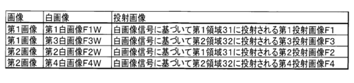
明るさ推定部241は、第1特定プロジェクター1Aが白色を示す白画像信号に基づいて第1領域31に投射する第1投射画像F1の明るさを推定する。白画像信号は、第1画像信号および第2画像信号の一例である。以下、白画像信号に基づいて第1領域31に投射される第1投射画像F1を「第1白画像F1W」と称する。第1白画像F1Wは、第1画像の一例である。明るさ推定部241は、第1白画像F1Wを示す第1撮像データを用いて、第1白画像F1Wの明るさを推定する。第1白画像F1Wを示す第1撮像データを生成するための撮像が実行される間、第2特定プロジェクター1B~第4特定プロジェクター1Dは、それぞれ、黒画像信号に基づいて黒画像を投射する。なお、第1白画像F1Wを示す第1撮像データを生成するための撮像が実行される間、第3特定プロジェクター1Cおよび第4特定プロジェクター1Dは、それぞれ、黒画像とは異なる画像、例えば、白画像信号に基づく画像を投射してもよい。
The
明るさ推定部241は、第2特定プロジェクター1Bが白画像信号に基づいて第1領域31に投射する第2投射画像F2の明るさを推定する。以下、白画像信号に基づいて第1領域31に投射される第2投射画像F2を「第2白画像F2W」と称する。第2白画像F2Wは、第2画像の一例である。明るさ推定部241は、第2白画像F2Wを示す第2撮像データを用いて、第2白画像F2Wの明るさを推定する。第2白画像F2Wを示す第2撮像データを生成するための撮像が実行される間、第1特定プロジェクター1Aと第3特定プロジェクター1Cと第4特定プロジェクター1Dは、それぞれ、黒画像信号に基づいて黒画像を投射する。なお、第2白画像F2Wを示す第2撮像データを生成するための撮像が実行される間、第3特定プロジェクター1Cおよび第4特定プロジェクター1Dは、それぞれ、黒画像とは異なる画像、例えば、白画像信号に基づく画像を投射してもよい。
The
明るさ推定部241は、第3特定プロジェクター1Cが白画像信号に基づいて第2領域32に投射する第3投射画像F3の明るさを推定する。以下、白画像信号に基づいて第2領域32に投射される第3投射画像F3を「第3白画像F3W」と称する。第3白画像F3Wは、第1画像の一例である。第1白画像F1Wと第3白画像F3Wは、複数の第1画像および複数の画像の一例である。明るさ推定部241は、第3白画像F3Wを示す第3撮像データを用いて、第3白画像F3Wの明るさを推定する。第3白画像F3Wを示す第3撮像データを生成するための撮像が実行される間、第1特定プロジェクター1Aと第2特定プロジェクター1Bと第4特定プロジェクター1Dは、それぞれ、黒画像信号に基づいて黒画像を投射する。なお、第3白画像F3Wを示す第3撮像データを生成するための撮像が実行される間、第1特定プロジェクター1Aおよび第2特定プロジェクター1Bは、それぞれ、黒画像とは異なる画像、例えば、白画像信号に基づく画像を投射してもよい。
The
明るさ推定部241は、第4特定プロジェクター1Dが白画像信号に基づいて第2領域32に投射する第4投射画像F4の明るさを推定する。以下、白画像信号に基づいて第2領域32に投射される第4投射画像F4を「第4白画像F4W」と称する。第4白画像F4Wは、第2画像の一例である。第2白画像F2Wと第4白画像F4Wは、複数の第2画像および複数の画像の一例である。明るさ推定部241は、第4白画像F4Wを示す第4撮像データを用いて、第4白画像F4Wの明るさを推定する。第4白画像F4Wを示す第4撮像データを生成するための撮像が実行される間、第1特定プロジェクター1A~第3特定プロジェクター1Cは、それぞれ、黒画像信号に基づいて黒画像を投射する。なお、第4白画像F4Wを示す第4撮像データを生成するための撮像が実行される間、第1特定プロジェクター1Aおよび第2特定プロジェクター1Bは、それぞれ、黒画像とは異なる画像、例えば、白画像信号に基づく画像を投射してもよい。
The
なお、第1特定プロジェクター1A~第4特定プロジェクター1Dは、それぞれ、白画像信号を、少なくとも初期色補正データおよび初期明るさ補正データに基づいて補正することによって、補正後の白画像信号を生成する。そして、第1特定プロジェクター1A~第4特定プロジェクター1Dは、それぞれ、補正後の白画像信号が示す画像を投射する。
このため、第1特定プロジェクター1A~第4特定プロジェクター1Dにおいて初期明るさ補正データが相互に異なる場合、第1白画像F1W~第4白画像F4Wの各々の明るさは、相互に異なる。
また、第1特定プロジェクター1A~第4特定プロジェクター1Dにおいて初期明るさ補正データが相互に異ならなくても、第1特定プロジェクター1A~第4特定プロジェクター1Dの個体差に基づいて、第1白画像F1W~第4白画像F4Wの各々の明るさは、相互に異なる可能性がある。
Note that each of the first
Therefore, when the initial brightness correction data of the first
Further, even if the initial brightness correction data of the first
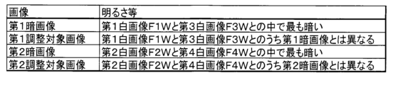
特定部242は、第1白画像F1Wと第3白画像F3Wとの明るさの推定結果に基づいて、第1白画像F1Wと第3白画像F3Wとの中で最も暗い第1暗画像と、第1白画像F1Wと第3白画像F3Wとのうち第1暗画像とは異なる第1調整対象画像と、を特定する。
特定部242は、第2白画像F2Wと第4白画像F4Wとの明るさの推定結果に基づいて、第2白画像F2Wと第4白画像F4Wとの中で最も暗い第2暗画像と、第2白画像F2Wと第4白画像F4Wとのうち第2暗画像とは異なる第2調整対象画像と、を特定する。
図7に第1画像および第2画像の一例を示す。また、図8に第1暗画像、第1調整対象画像、第2暗画像および第2調整対象画像の一例を示す。
The identifying
The specifying
FIG. 7 shows an example of the first image and the second image. Further, FIG. 8 shows an example of a first dark image, a first adjustment target image, a second dark image, and a second adjustment target image.
明るさ制御部243は、第1白画像F1Wが第1調整対象画像である場合、第1特定プロジェクター1Aを制御することによって、第1調整対象画像の明るさを第1暗画像の明るさに近づける。
明るさ制御部243は、第3白画像F3Wが第1調整対象画像である場合、第3特定プロジェクター1Cを制御することによって、第1調整対象画像の明るさを第1暗画像の明るさに近づける。
明るさ制御部243は、第2白画像F2Wが第2調整対象画像である場合、第2特定プロジェクター1Bを制御することによって、第2調整対象画像の明るさを第2暗画像の明るさに近づける。
明るさ制御部243は、第4白画像F4Wが第2調整対象画像である場合、第4特定プロジェクター1Dを制御することによって、第2調整対象画像の明るさを第2暗画像の明るさに近づける。
When the first white image F1W is the first adjustment target image, the
When the third white image F3W is the first adjustment target image, the
When the second white image F2W is the second adjustment target image, the
When the fourth white image F4W is the second adjustment target image, the
色推定部244は、第1特定プロジェクター1Aが赤色単色を示す赤画像信号に基づいて第1領域31に投射する第1投射画像F1の色の値を推定する。
色の値は、画像における赤成分の値と、当該画像における緑成分の値と、当該画像における青成分の値との組合せによって示される。色の値は、赤成分の値と、緑成分の値と、青成分の値との組合せに限らない。例えば、色の値は、XYZ表色系で示されるXYZ値で示されてもよい。
以下、赤画像信号に基づいて第1領域31に投射される第1投射画像F1を「第1赤画像F11」と称する。第1赤画像F11は、第3画像の一例である。第3画像は、第1赤画像F11に限らない。第1特定プロジェクター1Aが投射する第3画像は、緑色単色を示す緑画像信号に基づいて投射される画像でもよいし、青色単色を示す青画像信号に基づいて投射される画像でもよい。赤画像信号は、第3画像信号の一例である。第3画像信号は、赤画像信号に限らない。例えば、第3画像信号は、緑画像信号でもよいし、青画像信号でもよい。色推定部244は、第1赤画像F11を示す第1撮像データを用いて、第1赤画像F11の色の値を推定する。
The
A color value is represented by a combination of a red component value in an image, a green component value in the image, and a blue component value in the image. The color value is not limited to a combination of a red component value, a green component value, and a blue component value. For example, the color value may be expressed as an XYZ value expressed in an XYZ color system.
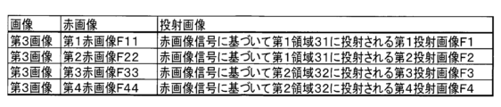
Hereinafter, the first projection image F1 projected onto the
第1赤画像F11を示す第1撮像データを生成するための撮像が実行される間、第2特定プロジェクター1B~第4特定プロジェクター1Dは、それぞれ、黒画像信号に基づいて黒画像を投射する。
なお、第1赤画像F11を示す第1撮像データを生成するための撮像が実行される間、第3特定プロジェクター1Cおよび第4特定プロジェクター1Dは、それぞれ、黒画像とは異なる画像、例えば、赤画像信号に基づく画像を投射してもよい。
While imaging is being performed to generate the first imaging data representing the first red image F11, the second
Note that while the imaging for generating the first imaging data indicating the first red image F11 is executed, the third
色推定部244は、第2特定プロジェクター1Bが赤画像信号に基づいて第1領域31に投射する第2投射画像F2の色の値を推定する。
以下、赤画像信号に基づいて第1領域31に投射される第2投射画像F2を「第2赤画像F22」と称する。第2赤画像F22は、第3画像の一例である。色推定部244は、第2赤画像F22を示す第2撮像データを用いて、第2赤画像F22の色の値を推定する。第2赤画像F22を示す第2撮像データを生成するための撮像が実行される間、第1特定プロジェクター1Aと第3特定プロジェクター1Cと第4特定プロジェクター1Dは、それぞれ、黒画像信号に基づいて黒画像を投射する。
なお、第2赤画像F22を示す第2撮像データを生成するための撮像が実行される間、第3特定プロジェクター1Cおよび第4特定プロジェクター1Dは、それぞれ、黒画像とは異なる画像、例えば、赤画像信号に基づく画像を投射してもよい。
The
Hereinafter, the second projection image F2 projected onto the
Note that while the imaging for generating the second imaging data indicating the second red image F22 is executed, the third
色推定部244は、第3特定プロジェクター1Cが赤画像信号に基づいて第2領域32に投射する第3投射画像F3の色の値を推定する。
以下、赤画像信号に基づいて第2領域32に投射される第3投射画像F3を「第3赤画像F33」と称する。第3赤画像F33は、第3画像の一例である。色推定部244は、第3赤画像F33を示す第3撮像データを用いて、第3赤画像F33の色の値を推定する。第3赤画像F33を示す第3撮像データを生成するための撮像が実行される間、第1特定プロジェクター1Aと第2特定プロジェクター1Bと第4特定プロジェクター1Dは、それぞれ、黒画像信号に基づいて黒画像を投射する。
なお、第3赤画像F33を示す第3撮像データを生成するための撮像が実行される間、第1特定プロジェクター1Aおよび第2特定プロジェクター1Bは、それぞれ、黒画像とは異なる画像、例えば、赤画像信号に基づく画像を投射してもよい。
The
Hereinafter, the third projection image F3 projected onto the
Note that while the imaging for generating the third imaging data indicating the third red image F33 is executed, the first
色推定部244は、第4特定プロジェクター1Dが赤画像信号に基づいて第2領域32に投射する第4投射画像F4の色の値を推定する。
以下、赤画像信号に基づいて第2領域32に投射される第4投射画像F4を「第4赤画像F44」と称する。第4赤画像F44は、第3画像の一例である。第1赤画像F11~第4赤画像F44は、複数の第3画像の一例である。色推定部244は、第4赤画像F44を示す第4撮像データを用いて、第4赤画像F44の色の値を推定する。第4赤画像F44を示す第4撮像データを生成するための撮像が実行される間、第1特定プロジェクター1A~第3特定プロジェクター1Cは、それぞれ、黒画像信号に基づいて黒画像を投射する。
なお、第4赤画像F44を示す第4撮像データを生成するための撮像が実行される間、第1特定プロジェクター1Aおよび第2特定プロジェクター1Bは、それぞれ、黒画像とは異なる画像、例えば、赤画像信号に基づく画像を投射してもよい。
The
Hereinafter, the fourth projection image F4 projected onto the
Note that while the imaging for generating the fourth imaging data indicating the fourth red image F44 is executed, the first
第1特定プロジェクター1A~第4特定プロジェクター1Dは、それぞれ、赤画像信号を、少なくとも初期色補正データおよび初期明るさ補正データに基づいて補正することによって、補正後の赤画像信号を生成する。そして、第1特定プロジェクター1A~第4特定プロジェクター1Dは、それぞれ、補正後の赤画像信号が示す画像を投射する。
このため、第1特定プロジェクター1A~第4特定プロジェクター1Dにおいて初期色補正データが相互に異なる場合、第1赤画像F11~第4赤画像F44の各々の色の値は、相互に異なる。
また、第1特定プロジェクター1A~第4特定プロジェクター1Dにおいて初期色補正データが相互に異ならなくても、第1特定プロジェクター1A~第4特定プロジェクター1Dの個体差に基づいて、第1赤画像F11~第4赤画像F44の各々の色の値は、相互に異なる可能性がある。
The first
Therefore, when the initial color correction data of the first
Furthermore, even if the initial color correction data of the first
色平均算出部245は、色推定部244による推定の結果に基づいて、第1赤画像F11の色の値と、第3赤画像F33の色の値と、の平均を求める。以下、第1赤画像F11の色の値と、第3赤画像F33の色の値と、の平均を「第1平均値」と称する。
また、色平均算出部245は、色推定部244による推定の結果に基づいて、第2赤画像F22の色の値と、第4赤画像F44の色の値と、の平均を求める。以下、第2赤画像F22の色の値と、第4赤画像F44の色の値と、の平均を「第2平均値」と称する。
The color
Further, the color
色制御部247は、第1赤画像F11と第3赤画像F33の中から、第1平均値と異なる色の値を示す第3調整対象画像を特定する。また、色制御部247は、第2赤画像F22と第4赤画像F44の中から、第2平均値と異なる色の値を示す第4調整対象画像を特定する。
図9に第3画像の一例を示す。また、図10に第3調整対象画像および第4調整対象画像の一例を示す。
The
FIG. 9 shows an example of the third image. Further, FIG. 10 shows an example of the third adjustment target image and the fourth adjustment target image.
色制御部247は、第1特定プロジェクター1Aと第3特定プロジェクター1Cのうち第3調整対象画像を投射するプロジェクターを制御することによって、第3調整対象画像の色の値を第1平均値に近づける。また、色制御部247は、第2特定プロジェクター1Bと第4特定プロジェクター1Dのうち第4調整対象画像を投射するプロジェクターを制御することによって、第4調整対象画像の色の値を第2平均値に近づける。
The
指示部248は、第1特定プロジェクター1A~第4特定プロジェクター1Dの各々に指示を送る。一例を挙げると、指示部248は、カメラ15が生成する撮像データにおける撮像座標と、液晶ライトバルブ145におけるパネル座標と、を相互に対応づけるキャリブレーション動作を実行する指示を、第1特定プロジェクター1A~第4特定プロジェクター1Dの各々に送る。
The
A4:明るさ制御の概要
図11は、明るさ制御の概要を説明するための図である。図11では、第1白画像F1Wの明るさを100%とする。この場合の第1白画像F1Wの明るさは、第1の明るさの一例である。第2白画像F2Wの明るさを、第1白画像F1Wの明るさの90%とする。この場合の第2白画像F2Wの明るさは、第2の明るさの一例である。第3白画像F3Wの明るさを、第1白画像F1Wの明るさの80%とする。この場合の第3白画像F3Wの明るさは、第3の明るさの一例である。第4白画像F4Wの明るさを、第1白画像F1Wの明るさの85%とする。この場合の第4白画像F4Wの明るさは、第4の明るさの一例である。
A4: Overview of Brightness Control FIG. 11 is a diagram for explaining an overview of brightness control. In FIG. 11, the brightness of the first white image F1W is set to 100%. The brightness of the first white image F1W in this case is an example of the first brightness. The brightness of the second white image F2W is set to 90% of the brightness of the first white image F1W. The brightness of the second white image F2W in this case is an example of second brightness. The brightness of the third white image F3W is set to 80% of the brightness of the first white image F1W. The brightness of the third white image F3W in this case is an example of the third brightness. The brightness of the fourth white image F4W is set to 85% of the brightness of the first white image F1W. The brightness of the fourth white image F4W in this case is an example of the fourth brightness.
この場合、特定部242は、第3白画像F3Wを第1暗画像として特定する。特定部242は、第1白画像F1Wを第1調整対象画像として特定する。特定部242は、第4白画像F4Wを第2暗画像として特定する。特定部242は、第2白画像F2Wを第2調整対象画像として特定する。
In this case, the identifying
明るさ制御部243は、第1特定プロジェクター1Aを制御することによって、第1白画像F1Wの明るさを100%から80%に落とす。このため、第1白画像F1Wの明るさは、第3白画像F3Wの明るさに近づき、第1白画像F1Wの明るさは、第3白画像F3Wの明るさと一致する。この場合、第1合成画像E1は、第3の明るさで表示される。したがって、第1合成画像E1における明るさのむらが低減する。
The
さらに、明るさ制御部243は、第2特定プロジェクター1Bを制御することによって、第2白画像F2Wの明るさを90%から85%に落とす。このため、第2白画像F2Wの明るさは、第4白画像F4Wの明るさに近づく。そして、第2白画像F2Wの明るさは、第4白画像F4Wの明るさと一致する。この場合、第2合成画像E2は、第4の明るさで表示される。したがって、第2合成画像E2における明るさのむらが低減する。
よって、第1合成画像E1が第2合成画像E2に重畳されている画像において明るさのむらが低減する。そして、それぞれ、タイリング投射された第1合成画像E1と、タイリング投射された第2合成画像E2とが、スタック投射された画像は、第1の明るさ、第2の明るさ、第3の明るさおよび第4の明るさより明るくなる。
なお、明るさ制御は、白画像だけでなく、少なくとも緑色のG成分を含んだ画像を用いることができる。例えば、単独のG画像や、R+G+B画像による単色画像を用いることができる。また、色調整は、白色、または、R、G、B単色毎に行うことができる。
Further, the
Therefore, unevenness in brightness is reduced in the image in which the first composite image E1 is superimposed on the second composite image E2. The first composite image E1, which has been projected in a tiling manner, and the second composite image E2, which has been projected in a tiled manner, are stack-projected, and the images have a first brightness, a second brightness, and a third brightness. and the fourth brightness.
Note that for brightness control, not only a white image but also an image containing at least a green G component can be used. For example, a single G image or a monochromatic image consisting of an R+G+B image can be used. Further, color adjustment can be performed for white or for each single color of R, G, and B.
A5:キャリブレーション動作
図12は、撮像座標とパネル座標とが相互に対応づけるキャリブレーション動作を説明するためのフローチャートである。以下では、第1特定プロジェクター1A~第4特定プロジェクター1Dは、黒画像信号に基づいて黒画像を投射しているとする。
ステップS101において第2操作部21が、キャリブレーション動作を実行するキャリブレーション指示を受けると、ステップS102において指示部248は、第1特定プロジェクター1A~第4特定プロジェクター1Dのうち動作対象プロジェクターとして未選択のプロジェクターの中から、一台の動作対象プロジェクターを選択する。
A5: Calibration Operation FIG. 12 is a flowchart for explaining a calibration operation in which imaging coordinates and panel coordinates are correlated with each other. In the following, it is assumed that the first
When the
続いて、ステップS103において指示部248は、パターン投射指示を第2通信部22から動作対象プロジェクターに送信する。
Subsequently, in step S103, the
動作対象プロジェクターでは、第1通信部13がパターン投射指示を受信すると、動作制御部171が、投射部14に、パターン画像を表示面3に対して投射させる。パターン画像は、例えば、格子パターンである。パターン画像の四隅には、所定のマークが形成されている。所定のマークは、パターン画像の四隅を検出する際に用いられる。第1記憶部16が、パターン画像を示すパターン画像データを記憶している場合、動作制御部171は、第1記憶部16からパターン画像データを読み出す。続いて、動作制御部171は、パターン画像データを示す画像信号を画像処理部141に出力することによって、投射部14に、パターン画像を表示面3に向けて投射させる。
In the projector to be operated, when the
指示部248は、パターン投射指示の送信後、ステップS104において対応づけ指示を第2通信部22から動作対象プロジェクターに送信する。
After transmitting the pattern projection instruction, the
動作対象プロジェクターでは、第1通信部13が対応づけ指示を受信すると、動作制御部171が、カメラ15に撮像を実行させる。カメラ15は、撮像を実行することによって撮像データを生成する。
動作制御部171は、撮像データにおける座標と、液晶ライトバルブ145における座標とを対応づける。撮像データにおける座標は、撮像座標とも称される。液晶ライトバルブ145における座標は、パネル座標とも称される。具体的には、動作制御部171は、まず、撮像データが示すパターン画像におけるマークを検出する。続いて、動作制御部171は、撮像データにおいてマークを示す画素の位置、すなわち、撮像データにおけるマークの撮像座標を特定する。続いて、動作制御部171は、液晶ライトバルブ145においてマークを示す画素の位置、すなわち、液晶ライトバルブ145におけるマークのパネル座標を特定する。続いて、動作制御部171は、撮像データにおけるマークの撮像座標と、液晶ライトバルブ145におけるマークのパネル座標と、を相互に対応づけたキャリブレーション情報を生成する。キャリブレーション情報において、撮像座標とパネル座標とが相互に対応づけられる。キャリブレーション情報は、座標変換情報とも称され得る。
In the operation target projector, when the
The
液晶ライトバルブ145においてマークを示す画素の位置は、例えば、事前に第1記憶部16に記憶されてもよい。この場合、動作制御部171は、第1記憶部16から、液晶ライトバルブ145においてマークを示す画素の位置を取得してもよい。
また、動作制御部171は、画像処理部141がパターン画像をフレームメモリー142に展開した際に、フレームメモリー142においてマークを示す画素の位置に基づいて、液晶ライトバルブ145においてマークを示す画素の位置を特定してもよい。この場合、第1記憶部16は、フレームメモリー142における画素の位置と、液晶ライトバルブ145における画素の位置とを、相互に対応づける位置対応情報を、事前に記憶する。動作制御部171は、位置対応情報を用いることによって、フレームメモリー142においてマークを示す画素の位置に基づいて、液晶ライトバルブ145においてマークを示す画素の位置を特定する。
続いて、動作制御部171は、投射部14にパターン画像の投射を終了させる。
続いて、動作制御部171は、キャリブレーション情報を、第1通信部13から制御装置2に送信する。なお、動作制御部171は、キャリブレーション情報の送信前にパターン画像の投射を終了させずに、キャリブレーション情報の送信後に、投射部14にパターン画像の投射を終了させてもよい。
The position of the pixel indicating the mark on the liquid crystal light valve 145 may be stored in the
Further, when the
Subsequently, the
Subsequently, the
ステップS105において第2通信部22が動作対象プロジェクターからキャリブレーション情報を受信すると、ステップS106において指示部248は、キャリブレーション情報を第2記憶部23に記憶する。
When the
続いて、ステップS107において指示部248は、第1特定プロジェクター1A~第4特定プロジェクター1Dの中で、動作対象プロジェクターとして未選択のプロジェクターが存在するか否かを判断する。
Subsequently, in step S107, the
ステップS107において未選択のプロジェクターが存在すると、処理がステップS102に戻る。ステップS102では、例えば指示部248は、第1特定プロジェクター1A、第2特定プロジェクター1B、第3特定プロジェクター1C、第4特定プロジェクター1Dの順に、動作対象プロジェクターを選択する。動作対象プロジェクターの選択における順序は、第1特定プロジェクター1A、第2特定プロジェクター1B、第3特定プロジェクター1C、第4特定プロジェクター1Dの順に限らず適宜変更可能である。
ステップS107において未選択のプロジェクターが存在しないと、図12に示す動作が終了する。
If there is an unselected projector in step S107, the process returns to step S102. In step S102, for example, the
If there is no unselected projector in step S107, the operation shown in FIG. 12 ends.
A6:明るさ調整動作
図13は、明るさ調整動作を説明するためのフローチャートである。以下では、第1特定プロジェクター1A~第4特定プロジェクター1Dは、黒画像信号に基づいて黒画像を投射しているとする。
ステップS201において第2操作部21が、明るさ調整を実行する明るさ調整指示を受けると、ステップS202において明るさ推定部241は、動作対象プロジェクターを選択する。ステップS202での動作は、上述のステップS102での動作と同様である。
A6: Brightness Adjustment Operation FIG. 13 is a flowchart for explaining the brightness adjustment operation. In the following, it is assumed that the first
When the
続いて、ステップS203において明るさ推定部241は、白画像を投射する指示を第2通信部22から動作対象プロジェクターに送信する。
Subsequently, in step S203, the
動作対象プロジェクターでは、第1通信部13が白画像を投射する指示を受信すると、動作制御部171が、投射部14に、白画像信号に基づく画像を表示面3に対して投射させる。白画像信号は、白色単色の白画像を示す。白画像信号は、白画像の階調として、設定可能な階調のうちの最大階調を示す。なお、白画像の階調は、設定可能な階調のうちの最大階調とは異なる階調でもよい。第1記憶部16が、白画像を示す白画像データを記憶している場合、動作制御部171は、第1記憶部16から白画像データを読み出す。続いて、動作制御部171は、白画像データを示す白画像信号を画像処理部141に出力することによって、投射部14に、白画像信号に基づく画像を表示面3に向けて投射させる。このため、例えば、第1特定プロジェクター1Aが動作対象プロジェクターとして選択されると、第1白画像F1Wが第1領域31に表示される。また、第2特定プロジェクター1Bが動作対象プロジェクターとして選択されると、第2白画像F2Wが第1領域31に表示される。
In the projector to be operated, when the
明るさ推定部241は、白画像を投射する指示の送信後、ステップS204において、撮像指示を第2通信部22から動作対象プロジェクターへ送信する。
After transmitting the instruction to project a white image, the
動作対象プロジェクターでは、第1通信部13が撮像指示を受信すると、動作制御部171は、カメラ15に撮像を実行させる。例えば、動作対象プロジェクターが第1特定プロジェクター1Aである場合、第1特定プロジェクター1Aにおけるカメラ15は、第1領域31に表示される第1白画像F1Wを撮像することによって、第1撮像データを生成する。
In the projector to be operated, when the
続いて、動作制御部171は、カメラ15が生成する撮像データを、第1通信部13から制御装置2に送信する。
Subsequently, the
ステップS205において第2通信部22が撮像データを受信すると、ステップS206において明るさ推定部241は、第2通信部22が受信した撮像データを第2記憶部23に記憶する。その後、明るさ推定部241は、黒画像を投射する指示を第2通信部22から動作対象プロジェクターに送信する。動作対象プロジェクターは、黒画像を投射する指示に従って、黒画像を投射する。
When the
続いて、ステップS207において明るさ推定部241は、未選択のプロジェクターが存在するか否かを判断する。ステップS207での動作は、上述のステップS107での動作と同様である。
Subsequently, in step S207, the
ステップS207において未選択のプロジェクターが存在する場合、処理がステップS202に戻る。ステップS207において未選択のプロジェクターが存在しない場合、ステップS208において明るさ推定部241は、第2記憶部23に記憶されている撮像データに基づいて、第1白画像F1W~第4白画像F4Wの各々の明るさを推定する。
If there are unselected projectors in step S207, the process returns to step S202. If there is no unselected projector in step S207, in step S208, the
例えば、明るさ推定部241は、まず、第1特定プロジェクター1Aのキャリブレーション情報を用いて、第1撮像データから、第1白画像F1Wを示す画素領域を特定する。続いて、明るさ推定部241は、第1白画像F1Wを示す画素領域内の各画素が示す輝度の平均を、第1白画像F1Wの明るさとして推定する。
なお、明るさ推定部241は、第1白画像F1Wを示す画素領域における特定位置、例えば、当該画素領域の中心に位置する画素が示す輝度を、第1白画像F1Wの明るさとして推定してもよい。この場合、輝度の平均を算出する処理を不要にすることができる。第1白画像F1Wを示す画素領域における特定位置は、第1白画像F1Wを示す画素領域の中心位置に限らず、第1白画像F1Wを示す画素領域のうち、中心位置とは異なる位置でもよい。
明るさ推定部241は、第2白画像F2W~第4白画像F4Wの明るさを、第1白画像F1Wの明るさを推定した手法と同様の手法で推定する。
For example, the
Note that the
The
続いて、ステップS209において特定部242は、明るさ推定部241による推定の結果に基づいて、第1白画像F1Wと第3白画像F3Wのうち、暗い画像を第1暗画像として特定し、他の画像を第1調整対象画像として特定する。
Subsequently, in step S209, the identifying
第1白画像F1Wの明るさが第3白画像F3Wの明るさと等しい場合、特定部242は、第1白画像F1Wと第3白画像F3Wの一方、例えば、第1白画像F1Wを第1暗画像として特定し、第1白画像F1Wと第3白画像F3Wの他方、例えば、第3白画像F3Wを第1調整対象画像として特定する。なお、第1白画像F1Wの明るさが第3白画像F3Wの明るさと等しい場合、ステップS209と後述のステップS210が省略されてもよい。
When the brightness of the first white image F1W is equal to the brightness of the third white image F3W, the identifying
ステップS209の完了後、ステップS210において明るさ制御部243は、第1白画像F1Wが第1調整対象画像である場合、第1特定プロジェクター1Aのみを制御することによって、第1調整対象画像の明るさを第1暗画像の明るさに近づける。
例えば、明るさ制御部243は、第1調整対象画像の明るさと第1暗画像の明るさとの差を示す第1明るさ補正データを生成する。続いて、明るさ制御部243は、第1特定プロジェクター1Aと第3特定プロジェクター1Cの各々に白画像を投射する指示を第2通信部22から送信する。続いて、明るさ制御部243は、第1明るさ補正データを、第1特定プロジェクター1Aのみに第2通信部22から送信することによって、第1特定プロジェクター1Aが投射する第1白画像F1Wの明るさを、明るさ補正データが示す明るさだけ暗くさせる。ここで、第1特定プロジェクター1Aでは、明るさ補正データを受信すると、第1白画像F1Wの明るさを、明るさ補正データが示す明るさだけ暗くする。
After completion of step S209, in step S210, if the first white image F1W is the first adjustment target image, the
For example, the
明るさ制御部243は、第3白画像F3Wが第1調整対象画像である場合、第3特定プロジェクター1Cのみを制御することによって、第1調整対象画像の明るさを第1暗画像の明るさに近づける。
第3白画像F3Wが第1調整対象画像である場合に第1調整対象画像の明るさを第1暗画像の明るさに近づける手法は、第1白画像F1Wが第1調整対象画像である場合に第1調整対象画像の明るさを第1暗画像の明るさに近づける手法と同様である。
When the third white image F3W is the first adjustment target image, the
When the third white image F3W is the first adjustment target image, the method of bringing the brightness of the first adjustment target image closer to the brightness of the first dark image is as follows: When the first white image F1W is the first adjustment target image, This is similar to the method of bringing the brightness of the first adjustment target image closer to the brightness of the first dark image.
続いて、ステップS211において特定部242は、明るさ推定部241による推定の結果に基づいて、第2白画像F2Wと第4白画像F4Wのうち、暗い画像を第2暗画像として特定し、他の画像を第2調整対象画像として特定する。
Subsequently, in step S211, the identifying
第2白画像F2Wの明るさが第4白画像F4Wの明るさと等しい場合、特定部242は、第2白画像F2Wと第4白画像F4Wの一方、例えば、第2白画像F2Wを第2暗画像として特定し、第2白画像F2Wと第4白画像F4Wの他方、例えば、第4白画像F4Wを第2調整対象画像として特定する。なお、第2白画像F2Wの明るさが第4白画像F4Wの明るさと等しい場合、ステップS211と後述のステップS212が省略されてもよい。
When the brightness of the second white image F2W is equal to the brightness of the fourth white image F4W, the identifying
ステップS211の完了後、ステップS212において明るさ制御部243は、第2白画像F2Wが第2調整対象画像である場合、第2特定プロジェクター1Bのみを制御することによって、第2調整対象画像の明るさを第2暗画像の明るさに近づける。
第2白画像F2Wが第2調整対象画像である場合に第2調整対象画像の明るさを第2暗画像の明るさに近づける手法は、第1白画像F1Wが第1調整対象画像である場合に第1調整対象画像の明るさを第1暗画像の明るさに近づける手法と同様である。
After completion of step S211, in step S212, if the second white image F2W is the second adjustment target image, the
When the second white image F2W is the second adjustment target image, the method of bringing the brightness of the second adjustment target image closer to the brightness of the second dark image is when the first white image F1W is the first adjustment target image. This is similar to the method of bringing the brightness of the first adjustment target image closer to the brightness of the first dark image.
明るさ制御部243は、第4白画像F4Wが第2調整対象画像である場合、第4特定プロジェクター1Dのみを制御することによって、第2調整対象画像の明るさを第2暗画像の明るさに近づける。
第4白画像F4Wが第2調整対象画像である場合に第2調整対象画像の明るさを第2暗画像の明るさに近づける手法は、第1白画像F1Wが第1調整対象画像である場合に第1調整対象画像の明るさを第1暗画像の明るさに近づける手法と同様である。
When the fourth white image F4W is the second adjustment target image, the
When the fourth white image F4W is the second adjustment target image, the method of bringing the brightness of the second adjustment target image closer to the brightness of the second dark image is when the first white image F1W is the first adjustment target image. This is similar to the method of bringing the brightness of the first adjustment target image closer to the brightness of the first dark image.
A7:色調整動作
図14は、色調整動作を説明するためのフローチャートである。以下では、第1特定プロジェクター1A~第4特定プロジェクター1Dは、黒画像信号に基づいて黒画像を投射しているとする。
ステップS301において第2操作部21が、色調整を実行する色調整指示を受けると、ステップS302において色推定部244は、第1特定プロジェクター1A~第4特定プロジェクター1Dのうち指示対象プロジェクターとして未選択のプロジェクターの中から、一台の指示対象プロジェクターを選択する。
A7: Color Adjustment Operation FIG. 14 is a flowchart for explaining the color adjustment operation. In the following, it is assumed that the first
When the
続いて、ステップS303において色推定部244は、赤画像を投射する指示を第2通信部22から指示対象プロジェクターに送信する。
Subsequently, in step S303, the
指示対象プロジェクターでは、第1通信部13が赤画像を投射する指示を受信すると、動作制御部171が、投射部14に、赤画像信号に基づく画像を表示面3に対して投射させる。赤画像信号は、赤画像の階調として、設定可能な階調のうちの中間階調を示す。なお、赤画像の階調は、中間階調と異なってもよい。第1記憶部16が、赤画像を示す赤画像データを記憶している場合、動作制御部171は、第1記憶部16から赤画像データを読み出す。続いて、動作制御部171は、赤画像データを示す赤画像信号を画像処理部141に出力することによって、投射部14に、赤画像信号に基づく画像を表示面3に対して投射させる。このため、例えば、第1特定プロジェクター1Aが指示対象プロジェクターとして選択されると、第1赤画像F11が第1領域31に表示される。また、第2特定プロジェクター1Bが指示対象プロジェクターとして選択されると、第2赤画像F22が第1領域31に表示される。
In the instruction target projector, when the
色推定部244は、赤画像を投射する指示の送信後、ステップS304において、撮像指示を第2通信部22から指示対象プロジェクターへ送信する。
After transmitting the instruction to project a red image, the
指示対象プロジェクターでは、第1通信部13が撮像指示を受信すると、動作制御部171は、カメラ15に撮像を実行させる。例えば、指示対象プロジェクターが第1特定プロジェクター1Aである場合、第1特定プロジェクター1Aにおけるカメラ15は、第1領域31に表示される第1赤画像F11を撮像することによって、第1撮像データを生成する。
In the instruction target projector, when the
続いて、動作制御部171は、カメラ15が生成する撮像データを、第1通信部13から制御装置2に送信する。
Subsequently, the
ステップS305において第2通信部22が撮像データを受信すると、ステップS306において色推定部244は、第2通信部が受信した撮像データを第2記憶部23に記憶する。その後、色推定部244は、黒画像を投射する指示を第2通信部22から指示対象プロジェクターに送信する。指示対象プロジェクターは、黒画像を投射する指示に従って、黒画像を投射する。
When the
続いて、ステップS307において色推定部244は、第1特定プロジェクター1A~第4特定プロジェクター1Dの中で指示対象プロジェクターとして未選択のプロジェクターが存在するか否かを判断する。
Subsequently, in step S307, the
ステップS307において未選択のプロジェクターが存在する場合、処理がステップS302に戻る。ステップS302では、例えば色推定部244は、第1特定プロジェクター1A、第2特定プロジェクター1B、第3特定プロジェクター1C、第4特定プロジェクター1Dの順に、指示対象プロジェクターを選択する。指示対象プロジェクターの選択における順序は、第1特定プロジェクター1A、第2特定プロジェクター1B、第3特定プロジェクター1C、第4特定プロジェクター1Dの順に限らず適宜変更可能である。
If there are unselected projectors in step S307, the process returns to step S302. In step S302, for example, the
ステップS307において未選択のプロジェクターが存在しない場合、ステップS308において色推定部244は、ステップS306で第2記憶部23に記憶された撮像データに基づいて、第1赤画像F11~第4赤画像F44の各々の色の値を推定する。
If there is no unselected projector in step S307, the
例えば、色推定部244は、まず、第1特定プロジェクター1Aのキャリブレーション情報を用いて、第1赤画像F11を示す第1撮像データから、第1赤画像F11を示す画素領域を特定する。
続いて、色推定部244は、第1赤画像F11を示す画素領域における中心に位置する画素が示す色、すなわち、当該中心に位置する画素における赤、緑および青の各画素値の組合せによって示される色の値を、第1赤画像F11の色の値として推定する。
第1赤画像F11を示す画素領域内の中心に位置する画素は、第1赤画像F11を示す画素領域内の所定領域の一例である。第1赤画像F11を示す画素領域内の所定領域は、第1赤画像F11を示す画素領域内の中心に位置する画素に限らない。
色推定部244は、第2赤画像F22~第4赤画像F44の各々の色の値についても、第1赤画像F11の色の値の推定手法と同様の手法で推定する。
For example, the
Next, the
The pixel located at the center of the pixel area representing the first red image F11 is an example of a predetermined area within the pixel area representing the first red image F11. The predetermined area within the pixel area showing the first red image F11 is not limited to the pixel located at the center within the pixel area showing the first red image F11.
The
続いて、ステップS309において色平均算出部245は、第1赤画像F11の色の値の推定結果と、第3赤画像F33の色の値の推定結果と、に基づいて、第1平均値を算出する。
Subsequently, in step S309, the color
例えば、色平均算出部245は、まず、第1赤画像F11の赤成分の値と、第3赤画像F33の赤成分の値と、の平均である赤成分平均値を算出する。続いて、色平均算出部245は、第1赤画像F11の緑成分の値と、第3赤画像F33の緑成分の値と、の平均である緑成分平均値を算出する。続いて、色平均算出部245は、第1赤画像F11の青成分の値と、第3赤画像F33の青成分の値と、の平均である青成分平均値を算出する。続いて、色平均算出部245は、赤成分平均値、緑成分平均値および青成分平均値の組合せによって特定される色の値を、第1平均値として決定する。第1平均値は、色の値の目標値として用いられる。赤成分平均値と緑成分平均値と青成分平均値の算出の順序は、適宜変更可能である。
For example, the color
続いて、ステップS310において色制御部247は、第1赤画像F11と第3赤画像F33との中で、第1平均値と異なる色の値を有する画像を、第3調整対象画像として特定する。
Subsequently, in step S310, the
続いて、ステップS311において色制御部247は、第1特定プロジェクター1Aおよび第3特定プロジェクター1Cのうち第3調整対象画像を投射するプロジェクターを制御することによって、第3調整対象画像の色の値を第1平均値に近づける。
例えば、色制御部247は、第3調整対象画像の色の値から第1平均値を差し引いた差分、具体的には、赤成分の値の差分、緑成分の値の差分および青成分の値の差分の組合せを第1色補正データとして生成する。続いて、色制御部247は、赤画像を投射する指示を第2通信部22から第1特定プロジェクター1Aおよび第3特定プロジェクター1Cの各々に送信する。続いて、色制御部247は、第1色補正データを、第2通信部22から第3調整対象画像を投射するプロジェクターに送信することによって、第3調整対象画像の色の値を第1平均値に近づけさせる。ここで、第3調整対象画像を投射するプロジェクターでは、第1色補正データを受信すると、投射中の画像の色の値を、第1補正データが示す差分だけ差し引いた値に変更することで、投射中の画像の色の値を第1平均値に近づける。
Subsequently, in step S311, the
For example, the
続いて、ステップS312において色平均算出部245は、第2赤画像F22の色の値の推定結果と、第4赤画像F44の色の値の推定結果と、に基づいて、第2平均値を算出する。第2平均値を算出する手法は、第1平均値を算出する手法と同様である。
Subsequently, in step S312, the color
続いて、ステップS313において色制御部247は、第2赤画像F22と第4赤画像F44との中で、第2平均値と異なる色の値を有する画像を、第4調整対象画像として特定する。
Subsequently, in step S313, the
続いて、ステップS314において色制御部247は、第2特定プロジェクター1Bおよび第4特定プロジェクター1Dのうち第4調整対象画像を投射するプロジェクターを制御することによって、第4調整対象画像の色の値を第2平均値に近づける。
第4調整対象画像の色の値を第2平均値に近づける手法は、第3調整対象画像の色の値を第1平均値に近づける手法と同様である。
Subsequently, in step S314, the
The method of bringing the color value of the fourth adjustment target image closer to the second average value is the same as the method of bringing the color value of the third adjustment target image closer to the first average value.
A8:第1実施形態についてのまとめ
上述の開示に係る制御方法および制御装置2は以下の態様を含む。
A8: Summary of the first embodiment The control method and
明るさ推定部241は、第1特定プロジェクター1Aに第1白画像F1Wを投射させ、第3特定プロジェクター1Cに第3白画像F3Wを投射させる。明るさ推定部241は、第1白画像F1Wと第3白画像F3Wの各々の明るさを推定する。明るさ推定部241は、第2特定プロジェクター1Bに第2白画像F2Wを投射させ、第4特定プロジェクター1Dに第4白画像F4Wを投射させる。明るさ推定部241は、第2白画像F2Wと第4白画像F4Wの各々の明るさを推定する。特定部242は、第1白画像F1Wと第3白画像F3Wの明るさの推定結果に基づいて、第1白画像F1Wと第3白画像F3Wの中から、最も暗い第1暗画像と、第1暗画像とは異なる第1調整対象画像と、を特定する。特定部242は、第2白画像F2Wと第4白画像F4Wの明るさの推定結果に基づいて、第2白画像F2Wと第4白画像F4Wの中から、最も暗い第2暗画像と、第2暗画像とは異なる第2調整対象画像と、を特定する。明るさ制御部243は、第1調整対象画像を投射するプロジェクターを制御することによって第1調整対象画像の明るさを第1暗画像の明るさに近づける。明るさ制御部243は、第2調整対象画像を投射するプロジェクターを制御することによって第2調整対象画像の明るさを第2暗画像の明るさに近づける。
例えば、明るさ制御部243は、第1白画像F1Wが第1調整対象画像である場合、第1特定プロジェクター1Aを制御することによって、第1調整対象画像の明るさを第1暗画像の明るさに近づける。明るさ制御部243は、第3白画像F3Wが第1調整対象画像である場合、第3特定プロジェクター1Cを制御することによって、第1調整対象画像の明るさを第1暗画像の明るさに近づける。明るさ制御部243は、第2白画像F2Wが第2調整対象画像である場合、第2特定プロジェクター1Bを制御することによって、第2調整対象画像の明るさを第2暗画像の明るさに近づける。明るさ制御部243は、第4白画像F4Wが第2調整対象画像である場合、第4特定プロジェクター1Dを制御することによって、第2調整対象画像の明るさを第2暗画像の明るさに近づける。
The
For example, when the first white image F1W is the first adjustment target image, the
この態様によれば、プロジェクションシステム2000を構成する第1特定プロジェクター1A~第4特定プロジェクター1Dの各々が投射する画像の明るさを、第1特定プロジェクター1A~第4特定プロジェクター1Dの各々が投射する画像のうち最も暗い画像の明るさに合わせる構成に比べて、プロジェクションシステム2000が表示する画像を明るくできる。
According to this aspect, each of the first
色推定部244は、第1特定プロジェクター1Aに第1赤画像F11を投射させ、第3特定プロジェクター1Cに第3赤画像F33を投射させる。色推定部244は、表示面3に表示される第1赤画像F11の色の値を推定する。色推定部244は、表示面3に表示される第3赤画像F33の色の値を推定する。色平均算出部245は、第1赤画像F11の色の値の推定結果と、第3赤画像F33の色の値の推定結果と、に基づいて、第1赤画像F11の色の値と、第3赤画像F33の色の値と、の平均である第1平均値を求める。色制御部247は、第1赤画像F11と第3赤画像F33との中から、第1平均値と異なる色の値を示す第3調整対象画像を特定する。色制御部247は、第3調整対象画像を投射するプロジェクターを制御することによって第3調整対象画像の色の値を第1平均値に近づける。
The
この態様によれば、色の目標値が、第1赤画像F11の色の値と第3赤画像F33の色の値との平均値となるので、第3調整対象画像の色の変更の程度を小さくできる。 According to this aspect, since the target color value is the average value of the color value of the first red image F11 and the color value of the third red image F33, the degree of change in color of the third adjustment target image can be made smaller.
第1領域31の一部は、第2領域32の一部と重なっている。このため、第1合成画像E1と第2合成画像E2の各々を1つの画像として形成できる。
A portion of the
B:変形例
以上に例示した実施形態の変形の態様を以下に例示する。以下の例示から任意に選択された2個以上の態様を、相互に矛盾しない範囲において適宜に併合してもよい。
B: Modifications Modifications of the embodiments exemplified above will be exemplified below. Two or more aspects arbitrarily selected from the following examples may be combined as appropriate within the range not contradicting each other.
B1:第1変形例
第1実施形態において、色平均算出部245は、第1赤画像F11と第3赤画像F33との中から、許容される色の値を有する赤画像を選択画像として選択し、選択画像の色の値の平均を求めてもよい。許容される色の値の範囲が、第2記憶部23に記憶される場合、色平均算出部245は、第1赤画像F11と第3赤画像F33の中から、第2記憶部23に記憶される許容される色の値の範囲に属する色の値を有する赤画像を選択画像として選択する。
この場合、色制御部247は、第1赤画像F11と第3赤画像F33の中から、選択画像の色の値の平均と異なる色の値を示す第3調整対象画像を特定し、第3調整対象画像を投射するプロジェクターを制御することによって第3調整対象画像の色の値を選択画像の色の値の平均に近づける。
B1: First Modified Example In the first embodiment, the color
In this case, the
この態様によれば、許容される色の値を有しない赤画像、例えば、画像処理において不具合の生じているプロジェクターが投射する画質の低い赤画像を、色の目標値を決定するための画像から除外できる。 According to this aspect, a red image that does not have an acceptable color value, for example, a low-quality red image projected by a projector that has a problem in image processing, is removed from the image for determining the target color value. Can be excluded.
B2:第2変形例
第1実施形態において、色平均算出部245は、第1赤画像F11の色の値と、第2赤画像F22の色の値と、第3赤画像F33の色の値と、第4赤画像F44の色の値と、の平均である第3平均値を求めてもよい。この場合、色制御部247は、第1赤画像F11~第4赤画像F44の中から、第3平均値と異なる色の値を示す第3調整対象画像を特定する。色制御部247は、第3調整対象画像を投射するプロジェクターを制御することによって第3調整対象画像の色の値を第3平均値に近づける。
この態様によれば、第1赤画像F11の色の値と、第2赤画像F22の色の値と、第3赤画像F33の色の値と、第4赤画像F44の色の値とを、相互に揃えることが可能である。
B2: Second Modification In the first embodiment, the color
According to this aspect, the color value of the first red image F11, the color value of the second red image F22, the color value of the third red image F33, and the color value of the fourth red image F44 are set. , it is possible to align them with each other.
B3:第3変形例
第1実施形態において、色平均算出部245は、第1赤画像F11の色の値と、第2赤画像F22の色の値と、第3赤画像F33の色の値と、第4赤画像F44の色の値と、の中から、許容される色の値を有する赤画像を選択画像として選択し、選択画像の色の値の平均を求めてもよい。許容される色の値の範囲が、第2記憶部23に記憶される場合、色平均算出部245は、第1赤画像F11の色の値と、第2赤画像F22の色の値と、第3赤画像F33の色の値と、第4赤画像F44の色の値と、の中から、第2記憶部23に記憶される許容される色の値の範囲に属する色の値を有する赤画像を選択画像として選択する。
この場合、色制御部247は、第1赤画像F11と第2赤画像F22と第3赤画像F33と第4赤画像F44の中から、選択画像の色の値の平均と異なる色の値を示す第3調整対象画像を特定し、第3調整対象画像を投射するプロジェクターを制御することによって第3調整対象画像の色の値を選択画像の色の値の平均に近づける。
この態様によれば、許容される色の値を有しない赤画像、例えば、画像処理において不具合の生じているプロジェクターが投射する画質の低い赤画像を、色の目標値を決定するための画像から除外できる。
B3: Third modification In the first embodiment, the color
In this case, the
According to this aspect, a red image that does not have an acceptable color value, for example, a low-quality red image projected by a projector that has a problem in image processing, is removed from the image for determining the target color value. Can be excluded.
B4:第4変形例
第1変形例において、指示部248は、第1赤画像F11と第3赤画像F33の中から、選択画像とは異なる非選択画像を特定してもよい。この場合、指示部248は、非選択画像を投射するプロジェクターに、ユーザーの注意を促す画像を投射させることが望ましい。ユーザーの注意を促す画像は、例えば「交換してください」という文字を表す画像である。ユーザーの注意を促す画像は、「交換してください」という文字を表す画像に限らない。例えば、ユーザーの注意を促す画像は、「修理してください」という文字を表す画像、または、交換作業を表す静止画でもよい。
B4: Fourth Modification In the first modification, the
また、第3変形例において、指示部248は、第1赤画像F11と第2赤画像F22と第3赤画像F33と第4赤画像F44の中から、選択画像とは異なる非選択画像を特定してもよい。この場合、指示部248は、非選択画像を投射するプロジェクターに、ユーザーの注意を促す画像を投射させることが望ましい。
In the third modification, the
この態様によれば、不具合が生じているプロジェクターをユーザーに知らせることが可能になる。 According to this aspect, it is possible to notify the user of the projector in which the problem is occurring.
B5:第5変形例
第1実施形態において、第1特定プロジェクター1Aおよび第3特定プロジェクター1Cの各々は、ユーザーによって設定されるユーザー設定補正データが設定されていない状況において画像信号に基づく画像を投射する場合、予め設定されている初期補正データに基づいて画像信号を補正することによって第1補正画像信号を生成し、第1補正画像信号が示す色の値を有する画像を投射してもよい。ここで、初期補正データは、第1特定プロジェクター1Aと第3特定プロジェクター1Cの個体差に起因する投射画像の色の違いを補正するために、出荷前に設定されるデータである。
B5: Fifth modification In the first embodiment, each of the first
さらに、第1特定プロジェクター1Aおよび第3特定プロジェクター1Cの各々は、ユーザー設定補正データが設定されている状況において画像信号に基づく画像を投射する場合、初期補正データとユーザー設定補正データとに基づいて画像信号を補正することによって第2補正画像信号を生成し、第2補正画像信号が示す色の値を有する画像を投射してもよい。
Further, when each of the first
B6:第6変形例
第5変形例において、色平均算出部245は、第1特定プロジェクター1Aと第3特定プロジェクター1Cの各々が生成する第1補正画像信号が示す色の値の平均を求めてもよい。色推定部244は、第1特定プロジェクター1Aと第3特定プロジェクター1Cに、赤画像信号に基づく画像を投射させ、表示面3に表示される複数の表示画像の色の値を推定してもよい。色制御部247は、当該複数の表示画像の中から、第1補正画像信号が示す色の値の平均と異なる色の値を示す第3調整対象画像を特定し、第3調整対象画像を投射するプロジェクターを制御することによって第3調整対象画像の色の値を、第1補正画像信号が示す色の値の平均に近づけてもよい。
B6: Sixth Modification In the fifth modification, the color
色平均算出部245は、第1特定プロジェクター1Aおよび第3特定プロジェクター1Cの各々が生成する第1補正画像信号を予め収集してもよいし、第1特定プロジェクター1Aおよび第3特定プロジェクター1Cの各々から初期補正データを収集してもよい。
The color
色平均算出部245は、初期補正データを収集する場合、第1特定プロジェクター1Aおよび第3特定プロジェクター1Cの各々について、初期補正データに基づいて赤画像信号を補正することによって第1補正画像信号を生成する。続いて、色平均算出部245は、第1特定プロジェクター1Aおよび第3特定プロジェクター1Cの各々の第1補正画像信号が示す色の平均を算出する。
When collecting initial correction data, the color
色平均算出部245は、例えば以下のように初期補正データを収集する。
色平均算出部245は、第2通信部22から第1特定プロジェクター1Aおよび第3特定プロジェクター1Cの各々に、初期補正データを要求する初期補正データ要求を送信する。色平均算出部245は、第1特定プロジェクター1Aおよび第3特定プロジェクター1Cの各々から、初期補正データ要求の応答として、初期補正データを、第2通信部22を介して受信する。
The color
The color
この態様によれば、例えば、第1特定プロジェクター1Aが投射する画像の色が、あるユーザーの好みでユーザー設定補正データにより変更されていても、この変更の影響を受けずに、色の目標値を決定できる。
According to this aspect, for example, even if the color of the image projected by the first
なお、第5変形例および第6変形例において、第1特定プロジェクター1Aおよび第3特定プロジェクター1Cの代わりに、第1特定プロジェクター1A~第4特定プロジェクター1Dが用いられてもよい。
Note that in the fifth modification and the sixth modification, the first
B7:第7変形例
第1実施形態において、色制御部247は、第1赤画像F11と第3赤画像F33の中から、第1特定プロジェクター1Aおよび第3特定プロジェクター1Cのいずれかである選定プロジェクターの投射画像と、選定プロジェクターの投射画像とは異なる第3調整対象画像と、を特定してもよい。この場合、色制御部247は、第3調整対象画像を投射するプロジェクターを制御することによって、第3調整対象画像の色の値を、選定プロジェクターの投射画像の色の値に近づける。
また、色制御部247は、第1赤画像F11~第4赤画像F44の中から、第1特定プロジェクター1A~第4特定プロジェクター1Dのいずれかである選定プロジェクターの投射画像と、選定プロジェクターの投射画像とは異なる第3調整対象画像と、を特定してもよい。この場合も、色制御部247は、第3調整対象画像を投射するプロジェクターを制御することによって、第3調整対象画像の色の値を、選定プロジェクターの投射画像の色の値に近づける。
この態様によれば、平均を算出する処理を不要にできる。よって、色平均算出部245を省略できる。
B7: Seventh Modification In the first embodiment, the
The
According to this aspect, the process of calculating the average can be made unnecessary. Therefore, the color
B8:第8変形例
第5変形例において、色制御部247は、第1赤画像F11および第3赤画像F33の中から、第1特定プロジェクター1Aと第3特定プロジェクター1Cのいずれかである選定プロジェクターが生成する第1補正画像信号が示す色の値と異なる色の値を示す第3調整対象画像を特定してもよい。色制御部247は、第3調整対象画像を投射するプロジェクターを制御することによって第3調整対象画像の色の値を、選定プロジェクターが生成する第1補正画像信号が示す色の値に近づける。
この態様によれば、例えば、選定プロジェクターとは異なるプロジェクターが投射する画像の色が、あるユーザーの好みで変更されていても、この変更の影響を受けずに、色の目標値を決定できる。また、平均を算出する処理を不要にできる。よって、色平均算出部245を省略できる。
B8: Eighth Modification In the fifth modification, the
According to this aspect, for example, even if the color of an image projected by a projector different from the selected projector is changed according to a certain user's preference, the target color value can be determined without being affected by this change. Further, the process of calculating the average can be made unnecessary. Therefore, the color
なお、第5変形例および第8変形例において、第1特定プロジェクター1Aおよび第3特定プロジェクター1Cの代わりに、第1特定プロジェクター1A~第4特定プロジェクター1Dが用いられてもよい。
Note that in the fifth modification and the eighth modification, the first to fourth
B9:第9変形例
第1実施形態および第1~第8変形例において、第1白画像F1Wと第3白画像F3Wの各々の明るさを推定する期間では、明るさ推定部241は、第2特定プロジェクター1Bおよび第4特定プロジェクター1Dに黒色の画像を投射させることが望ましい。
この態様によれば、第1白画像F1Wと第3白画像F3Wの各々の明るさを推定する期間において、第2特定プロジェクター1Bおよび第4特定プロジェクター1Dに対して電源供給を停止し、その後、電源供給を実行する構成に比べて、第2特定プロジェクター1Bおよび第4特定プロジェクター1Dへの電源供給を維持できるため、第2特定プロジェクター1Bおよび第4特定プロジェクター1Dの動作を迅速にできる。
B9: Ninth Modified Example In the first embodiment and the first to eighth modified examples, during the period in which the brightness of each of the first white image F1W and the third white image F3W is estimated, the
According to this aspect, during the period in which the brightness of each of the first white image F1W and the third white image F3W is estimated, the power supply to the second
B10:第10変形例
第7変形例または第8変形例において、色制御部247は、選定プロジェクターを自動的に決定してもよい。例えば、色制御部247は、選定プロジェクターをランダムに自動的に決定する。
この態様によれば、選定プロジェクターが自動的に決定されるので、ユーザーが選定プロジェクターを指定する手間を省くことができる。
B10: Tenth Modification In the seventh modification or the eighth modification, the
According to this aspect, since the selected projector is automatically determined, it is possible to save the user the trouble of specifying the selected projector.
B11:第11変形例
第7変形例、第8変形例または第10変形例において、選定プロジェクターにおける投射レンズのシフト量が、第1特定プロジェクター1A~第4特定プロジェクター1Dのうち、選定プロジェクター以外のプロジェクターにおける投射レンズのシフト量よりも小さくてもよい。
例えば、第10変形例において色制御部247は、色推定部244による色の値の推定処置の完了後、第1特定プロジェクター1A~第4特定プロジェクター1Dの各々から、投射レンズのシフト量を示すシフト量情報を取得する。
色制御部247は、第1特定プロジェクター1A~第4特定プロジェクター1Dの各々から取得したシフト量情報を用いて、選定プロジェクターを特定する。投射レンズのシフト量が小さいほど、プロジェクターは表示面3の正面に位置する可能性が大きい。このため、この態様によれば、表示面3の正面に位置する可能性が大きいプロジェクターを、選定プロジェクターとして用いることが可能になる。
B11: Eleventh Modification In the seventh modification, the eighth modification, or the tenth modification, the shift amount of the projection lens in the selected projector is different from that of the selected projector among the first
For example, in the tenth modification, the
The
B12:第12変形例
第1調整対象画像の明るさを第1暗画像の明るさに近づけ、かつ、第2調整対象画像の明るさを第2暗画像の明るさに近づける処理の実行後では、第1合成画像E1が第2合成画像E2と重畳することによって形成される重畳画像は、理想的には、図11において、E1+E2で示される画像のように明るさにむらが生じない。
B12: Twelfth modification example After executing the process of bringing the brightness of the first adjustment target image closer to the brightness of the first dark image and bringing the brightness of the second adjustment target image closer to the brightness of the second dark image. , the superimposed image formed by superimposing the first composite image E1 and the second composite image E2 ideally does not have uneven brightness like the image shown by E1+E2 in FIG.
しかしながら、明るさ推定部241での推定誤差等が原因となって、当該重畳画像において明るさのむらが生じるおそれがある。第12変形例では、プロジェクションシステム2000は、当該重畳画像における明るさのむらを目立たなくするために、さらに複数の第3プロジェクターを含む。
However, due to an estimation error in the
図15は、第5特定プロジェクター1Eと第6特定プロジェクター1Fとをさらに含むプロジェクションシステム2000を示す図である。第5特定プロジェクター1Eと第6特定プロジェクター1Fは、複数の第3プロジェクターの一例である。第5特定プロジェクター1Eは、一の第3プロジェクターの一例である。
FIG. 15 is a diagram showing a
第5特定プロジェクター1Eと第6特定プロジェクター1Fは、それぞれ、第1特定プロジェクター1A~第4特定プロジェクター1Dの各々と同一構成である。第5特定プロジェクター1Eは、第1領域31と対応する。第6特定プロジェクター1Fは、第2領域32と対応する。第5特定プロジェクター1Eは、第1領域31に画像を投射する。第5特定プロジェクター1Eが投射する画像の内容は、第1投射画像F1の内容および第2投射画像F2の内容と同一である。第6特定プロジェクター1Fは、第2領域32に画像を投射する。第6特定プロジェクター1Fが投射する画像の内容は、第3投射画像F3の内容および第4投射画像F4の内容と同一である。
The fifth
明るさ推定部241は、第1調整対象画像の明るさを第1暗画像の明るさに近づけ、かつ、第2調整対象画像の明るさを第2暗画像の明るさに近づける処理の実行後、第1特定プロジェクター1A~第6特定プロジェクター1Fの各々に白画像を投射する指示を送信する。
After the
明るさ推定部241は、第1特定プロジェクター1A~第6特定プロジェクター1Fの各々に白画像を投射する指示を送信した後、第1特定プロジェクター1Aおよび第3特定プロジェクター1Cに対して、撮像指示を送信する。
After transmitting an instruction to project a white image to each of the first
第1特定プロジェクター1Aおよび第3特定プロジェクター1Cでは、撮像指示に応じて、カメラ15は、表示面3を撮像することによって撮像データを生成する。動作制御部171は、撮像データを第1通信部13から制御装置2に送信する。
In the first
明るさ推定部241は、第1特定プロジェクター1Aから受信した撮像データに基づいて、第1領域31の明るさを推定する。明るさ推定部241は、第3特定プロジェクター1Cから受信した撮像データに基づいて、第2領域32の明るさを推定する。明るさ推定部241は、第1領域31の明るさと第2領域32の明るさとの差分を算出する。明るさ推定部241は、この差分を、第1領域31と第2領域32にて構成される領域における明るさのむらと推定する。
The
色制御部247は、明るさのむらの推定結果に基づいて、第5特定プロジェクター1Eと第6特定プロジェクター1Fとの少なくとも一を制御することによって、第1領域31と第2領域32にて構成される領域における明るさのむらを、第5特定プロジェクター1Eと第6特定プロジェクター1Fとの少なくとも一の制御前における当該領域の明るさのむらよりも小さくする。
The
例えば、明るさ制御部243は、第1領域31が第2領域32よりも明るい場合、第1領域31の明るさと第2領域32の明るさとの差分だけ、第5特定プロジェクター1Eの投射画像の明るさを低くさせる第1補正データを、第2通信部22から第5特定プロジェクター1Eに送信する。第5特定プロジェクター1Eは、第1補正データに基づいて、第1領域31の明るさと第2領域32の明るさとの差分だけ投射画像の明るさを低くする。
For example, when the
第2領域32が第1領域31よりも明るい場合、明るさ制御部243は、第1領域31の明るさと第2領域32の明るさとの差分だけ、第6特定プロジェクター1Fの投射画像の明るさを低くさせる第2補正データを、第2通信部22から第6特定プロジェクター1Fに送信する。第6特定プロジェクター1Fは、第2補正データに基づいて、第1領域31の明るさと第2領域32の明るさとの差分だけ投射画像の明るさを低くする。
When the
この態様によれば、第1領域31の明るさと第2領域32の明るさとの違いを目立ち難くできる。
According to this aspect, the difference between the brightness of the
B13:第13変形例
第1実施形態および第1~第12変形例において、プロジェクター1における光変調装置の一例として液晶ライトバルブ145が用いられたが、光変調装置は液晶ライトバルブに限らず適宜変更可能である。例えば、光変調装置は、3枚の反射型の液晶パネルを用いた構成であってもよい。また、光変調装置は、1枚の液晶パネルを用いた方式、3枚のデジタルミラーデバイス(DMD)を用いた方式、1枚のデジタルミラーデバイスを用いた方式等の構成であってもよい。光変調装置として1枚のみの液晶パネルまたはDMDが用いられる場合、色分離光学系および色合成光学系に相当する部材は不要である。また、液晶パネルおよびDMD以外にも、光源144が発した光を変調可能な構成は、光変調装置として採用できる。
B13: Thirteenth Modification In the first embodiment and the first to twelfth modifications, the liquid crystal light valve 145 was used as an example of a light modulation device in the projector 1, but the light modulation device is not limited to the liquid crystal light valve, and may be used as appropriate. Can be changed. For example, the light modulation device may have a configuration using three reflective liquid crystal panels. Further, the light modulation device may have a configuration such as a system using one liquid crystal panel, a system using three digital mirror devices (DMD), a system using one digital mirror device, or the like. When only one liquid crystal panel or DMD is used as the light modulation device, members corresponding to the color separation optical system and the color synthesis optical system are not required. Furthermore, in addition to the liquid crystal panel and the DMD, any structure capable of modulating the light emitted by the
B14:第14変形例
第1実施形態および第1~第13変形例において、1台のカメラ15が全ての画像の撮像を行ってもよい。この場合、1台のカメラ15は、第1特定プロジェクター1A~第4特定プロジェクター1Dのいずれのプロジェクターにも搭載されてもよいし、いずれにも搭載されていなくてもよい。
B14: Fourteenth Modification In the first embodiment and the first to thirteenth modifications, one
B15:第15変形例
第1実施形態および第1~第14変形例において、指示部248は、パターン投射指示の代わりにパターン画像データを送信してもよい。この場合、プロジェクター1における動作制御部171は、指示部248から送信されたパターン画像データを画像処理部141に出力する。
第1実施形態および第1~第11変形例において、明るさ推定部241は、白画像を投射する指示の代わりに白画像データを送信してもよい。この場合、プロジェクター1における動作制御部171は、明るさ推定部241から送信された白画像データを画像処理部141に出力する。
第1実施形態および第1~第11変形例において、色推定部244は、赤画像を投射する指示の代わりに赤画像データを送信してもよい。この場合、プロジェクター1における動作制御部171は、色推定部244から送信された赤画像データを画像処理部141に出力する。
第1実施形態および第1~第11変形例において、明るさ推定部241は、黒画像を投射する指示の代わりに黒画像データを送信してもよい。この場合、プロジェクター1における動作制御部171は、明るさ推定部241から送信された黒画像データを画像処理部141に出力する。
B15: Fifteenth Modification In the first embodiment and the first to fourteenth modifications, the
In the first embodiment and the first to eleventh modified examples, the
In the first embodiment and the first to eleventh modified examples, the
In the first embodiment and the first to eleventh modified examples, the
1…プロジェクター、1A…第1特定プロジェクター、1B…第2特定プロジェクター、1C…第3特定プロジェクター、1D…第4特定プロジェクター、2…制御装置、21…第2操作部、22…第2通信部、23…第2記憶部、24…第2処理部、141…画像処理部、142…フレームメモリー、143…ライトバルブ駆動部、144…光源、145…液晶ライトバルブ、145B…青色用液晶ライトバルブ、145G…緑色用液晶ライトバルブ、145R…赤色用液晶ライトバルブ、146…投射光学系、151…受光光学系、152…撮像素子、171…動作制御部、173…画質補正部、241…明るさ推定部、242…特定部、243…明るさ制御部、244…色推定部、245…色平均算出部、247…色制御部、248…指示部、1000…表示システム、2000…プロジェクションシステム。 DESCRIPTION OF SYMBOLS 1...Projector, 1A...First specific projector, 1B...Second specific projector, 1C...Third specific projector, 1D...Fourth specific projector, 2...Control device, 21...Second operating unit, 22...Second communication unit , 23... Second storage section, 24... Second processing section, 141... Image processing section, 142... Frame memory, 143... Light valve drive section, 144... Light source, 145... Liquid crystal light valve, 145B... Blue liquid crystal light valve , 145G...LCD light valve for green, 145R...LCD light valve for red, 146...Projection optical system, 151...Light receiving optical system, 152...Image sensor, 171...Operation control section, 173...Image quality correction section, 241...Brightness Estimation section, 242... Specification section, 243... Brightness control section, 244... Color estimation section, 245... Color average calculation section, 247... Color control section, 248... Instruction section, 1000... Display system, 2000... Projection system.
Claims (7)
前記複数の第1プロジェクターのうちの一の第1プロジェクターが、前記複数の第1プロジェクターにそれぞれ対応する複数の表示領域のうち前記一の第1プロジェクターに対応する一の表示領域に画像を投射し、かつ、前記複数の第2プロジェクターのうち前記一の表示領域に対応する一の第2プロジェクターが、前記一の表示領域に画像を投射することにより、前記複数の第1プロジェクターと1対1で対応する複数の画像のうちの一の画像と、前記複数の第2プロジェクターと1対1で対応する複数の画像のうちの一の画像とを、前記一の表示領域に表示し、
前記制御装置は、
前記複数の第1プロジェクターの各々に投射させた複数の第1画像の各々の明るさを推定し、前記複数の第2プロジェクターの各々に第2画像を投射させ、複数の第2画像の各々の明るさを推定し、
前記複数の第1画像の各々の明るさの推定結果に基づいて、前記複数の第1画像の中から、最も暗い第1暗画像と、前記第1暗画像とは異なる第1調整対象画像と、を特定し、前記複数の第2画像の各々の明るさの推定結果に基づいて、前記複数の第2画像の中から、最も暗い第2暗画像と、前記第2暗画像とは異なる第2調整対象画像と、を特定し、
前記第1調整対象画像を投射するプロジェクターを制御することによって前記第1調整対象画像の明るさを前記第1暗画像の明るさに近づけ、前記第2調整対象画像を投射するプロジェクターを制御することによって前記第2調整対象画像の明るさを前記第2暗画像の明るさに近づけ、
前記複数の第1プロジェクターに単色の第3画像を投射させ、前記複数の表示領域を含む表示面に表示される複数の第3画像の色の値を推定し、
前記色の値の推定結果に基づいて、前記複数の第3画像のうち、許容される色の値を有する第3画像を、選択画像として特定し、
前記選択画像の色の値の平均を求め、
前記複数の第3画像の中から、前記平均と異なる色の値を示す第3調整対象画像を特定し、前記第3調整対象画像を投射するプロジェクターを制御することによって前記第3調整対象画像の色の値を前記平均に近づける、
ことを特徴とする、表示システムの制御方法。
A method for controlling a display system including a plurality of first projectors, a plurality of second projectors, and a control device, the method comprising:
One first projector of the plurality of first projectors projects an image onto one display area corresponding to the one first projector among the plurality of display areas respectively corresponding to the plurality of first projectors. , and one second projector corresponding to the one display area among the plurality of second projectors projects an image onto the one display area, thereby providing a one-on-one relationship with the plurality of first projectors. displaying one image among the plurality of corresponding images and one image among the plurality of images corresponding one-to-one with the plurality of second projectors in the one display area;
The control device includes:
Estimating the brightness of each of the plurality of first images projected by each of the plurality of first projectors, causing each of the plurality of second projectors to project a second image, and estimating the brightness of each of the plurality of second images. Estimate the brightness,
Based on the brightness estimation result of each of the plurality of first images, a first dark image that is the darkest from among the plurality of first images, and a first adjustment target image different from the first dark image. , and based on the estimation result of the brightness of each of the plurality of second images, select a second dark image that is the darkest from among the plurality of second images and a second dark image different from the second dark image. 2. Identify the image to be adjusted, and
controlling a projector that projects the first adjustment target image to bring the brightness of the first adjustment target image closer to the brightness of the first dark image, and controlling a projector that projects the second adjustment target image; bringing the brightness of the second adjustment target image closer to the brightness of the second dark image ,
projecting monochromatic third images on the plurality of first projectors, estimating color values of the plurality of third images displayed on a display surface including the plurality of display areas;
Based on the color value estimation result, specifying a third image having an acceptable color value among the plurality of third images as a selected image;
determining the average of the color values of the selected images;
From among the plurality of third images, a third adjustment target image having a color value different from the average is specified, and the third adjustment target image is controlled by controlling a projector that projects the third adjustment target image. bringing the color value closer to said average;
A method for controlling a display system, characterized in that:
前記複数の第1プロジェクターのうちの一の第1プロジェクターが、前記複数の第1プロジェクターにそれぞれ対応する複数の表示領域のうち前記一の第1プロジェクターに対応する一の表示領域に画像を投射し、かつ、前記複数の第2プロジェクターのうち前記一の表示領域に対応する一の第2プロジェクターが、前記一の表示領域に画像を投射することにより、前記複数の第1プロジェクターと1対1で対応する複数の画像のうちの一の画像と、前記複数の第2プロジェクターと1対1で対応する複数の画像のうちの一の画像とを、前記一の表示領域に表示し、
前記制御装置は、
前記複数の第1プロジェクターの各々に投射させた複数の第1画像の各々の明るさを推定し、前記複数の第2プロジェクターの各々に第2画像を投射させ、複数の第2画像の各々の明るさを推定し、
前記複数の第1画像の各々の明るさの推定結果に基づいて、前記複数の第1画像の中から、最も暗い第1暗画像と、前記第1暗画像とは異なる第1調整対象画像と、を特定し、前記複数の第2画像の各々の明るさの推定結果に基づいて、前記複数の第2画像の中から、最も暗い第2暗画像と、前記第2暗画像とは異なる第2調整対象画像と、を特定し、
前記第1調整対象画像を投射するプロジェクターを制御することによって前記第1調整対象画像の明るさを前記第1暗画像の明るさに近づけ、前記第2調整対象画像を投射するプロジェクターを制御することによって前記第2調整対象画像の明るさを前記第2暗画像の明るさに近づけ、
前記複数の第1プロジェクターと前記複数の第2プロジェクターに単色の第3画像を投射させ、前記複数の表示領域を含む表示面に表示される複数の第3画像の色の値を推定し、
前記色の値の推定結果に基づいて、前記複数の第3画像から、許容される色の値を有する選択画像を選択し、
前記選択画像の色の値の平均を求め、
前記複数の第3画像の中から、前記平均と異なる色の値を示す第3調整対象画像を特定し、前記第3調整対象画像を投射するプロジェクターを制御することによって前記第3調整対象画像の色の値を前記平均に近づける、
ことを特徴とする、表示システムの制御方法。
A method for controlling a display system including a plurality of first projectors, a plurality of second projectors, and a control device, the method comprising:
One first projector of the plurality of first projectors projects an image onto one display area corresponding to the one first projector among the plurality of display areas respectively corresponding to the plurality of first projectors. , and one second projector corresponding to the one display area among the plurality of second projectors projects an image onto the one display area, thereby providing a one-on-one relationship with the plurality of first projectors. displaying one image among the plurality of corresponding images and one image among the plurality of images corresponding one-to-one with the plurality of second projectors in the one display area;
The control device includes:
Estimating the brightness of each of the plurality of first images projected by each of the plurality of first projectors, causing each of the plurality of second projectors to project a second image, and estimating the brightness of each of the plurality of second images. Estimate the brightness,
Based on the brightness estimation result of each of the plurality of first images, a first dark image that is the darkest from among the plurality of first images, and a first adjustment target image different from the first dark image. , and based on the estimation result of the brightness of each of the plurality of second images, select a second dark image that is the darkest from among the plurality of second images and a second dark image different from the second dark image. 2. Identify the image to be adjusted, and
controlling a projector that projects the first adjustment target image to bring the brightness of the first adjustment target image closer to the brightness of the first dark image, and controlling a projector that projects the second adjustment target image; bringing the brightness of the second adjustment target image closer to the brightness of the second dark image ,
projecting monochromatic third images on the plurality of first projectors and the plurality of second projectors, estimating color values of the plurality of third images displayed on a display surface including the plurality of display areas;
selecting a selected image having an acceptable color value from the plurality of third images based on the color value estimation result;
determining the average of the color values of the selected images;
From among the plurality of third images, a third adjustment target image having a color value different from the average is specified, and the third adjustment target image is controlled by controlling a projector that projects the third adjustment target image. bringing the color value closer to said average;
A method for controlling a display system, characterized in that:
前記複数の第3画像の中から前記選択画像とは異なる非選択画像を特定し、
前記非選択画像を投射するプロジェクターに、ユーザーの注意を促す画像を投射させる、
請求項1または2に記載の表示システムの制御方法。
The control device includes:
identifying a non-selected image different from the selected image from among the plurality of third images;
causing the projector that projects the non-selected image to project an image that calls the user's attention;
A method for controlling a display system according to claim 1 or 2.
前記複数の第1画像の各々の明るさを推定する期間では、
前記複数の第2プロジェクターの各々に黒色の画像を投射させる、
請求項1から3のいずれか1項に記載の制御方法。
The control device includes:
In the period of estimating the brightness of each of the plurality of first images,
projecting a black image on each of the plurality of second projectors;
The control method according to any one of claims 1 to 3 .
前記複数の第3プロジェクターのうちの一の第3プロジェクターは、
前記複数の表示領域のうち前記一の第3プロジェクターに対応する一の表示領域に画像を投射し、
前記制御装置は、
前記第1調整対象画像の明るさを前記第1暗画像の明るさに近づけ、かつ、前記第2調整対象画像の明るさを前記第2暗画像の明るさに近づける処理の実行後、前記複数の表示領域にて構成される領域における明るさのむらを推定し、
前記明るさのむらの推定結果に基づいて、前記複数の第3プロジェクターの少なくとも一を制御することによって、前記複数の第3プロジェクターの制御後における前記領域における明るさのむらを、前記複数の第3プロジェクターの少なくとも一の制御前における前記領域の明るさのむらよりも小さくする、
請求項1から4のいずれか1項に記載の表示システムの制御方法。
The display system further includes a plurality of third projectors,
One third projector among the plurality of third projectors is:
Projecting an image onto one display area corresponding to the one third projector among the plurality of display areas;
The control device includes:
After performing a process of bringing the brightness of the first adjustment target image closer to the brightness of the first dark image and bringing the brightness of the second adjustment target image closer to the brightness of the second dark image, the plurality of Estimate the unevenness of brightness in the area consisting of the display area of
By controlling at least one of the plurality of third projectors based on the estimation result of the brightness unevenness, the brightness unevenness in the area after controlling the plurality of third projectors is reduced by controlling at least one of the plurality of third projectors. less than the uneven brightness of the area before at least one of the controls;
A method for controlling a display system according to any one of claims 1 to 4 .
前記複数の第1プロジェクターの各々に投射させた複数の第1画像の各々の明るさを推定し、前記複数の第2プロジェクターの各々に第2画像を投射させ、複数の第2画像の各々の明るさを推定する推定部と、
前記複数の第1画像の各々の明るさの推定結果に基づいて、前記複数の第1画像の中から、最も暗い第1暗画像と、前記第1暗画像とは異なる第1調整対象画像と、を特定し、前記複数の第2画像の各々の明るさの推定結果に基づいて、前記複数の第2画像の中から、最も暗い第2暗画像と、前記第2暗画像とは異なる第2調整対象画像と、を特定する特定部と、
前記第1調整対象画像を投射するプロジェクターを制御することによって前記第1調整対象画像の明るさを前記第1暗画像の明るさに近づけ、前記第2調整対象画像を投射するプロジェクターを制御することによって前記第2調整対象画像の明るさを前記第2暗画像の明るさに近づける明るさ制御部と、
を含み、
前記複数の第1プロジェクターに単色の第3画像を投射させ、前記複数の表示領域を含む表示面に表示される複数の第3画像の色の値を推定し、
前記色の値の推定結果に基づいて、前記複数の第3画像のうち、許容される色の値を有する第3画像を、選択画像として特定し、
前記選択画像の色の値の平均を求め、
前記複数の第3画像の中から、前記平均と異なる色の値を示す第3調整対象画像を特定し、前記第3調整対象画像を投射するプロジェクターを制御することによって前記第3調整対象画像の色の値を前記平均に近づける、
ことを特徴とする、制御装置。
including a plurality of first projectors and a plurality of second projectors, one of the first projectors of the plurality of first projectors covers one of the plurality of display areas respectively corresponding to the plurality of first projectors. An image is projected onto one display area corresponding to the first projector, and one second projector corresponding to the one display area among the plurality of second projectors projects an image onto the one display area. By doing so, one image among the plurality of images corresponds one-to-one with the plurality of first projectors, and one image among the plurality of images corresponds one-to-one with the plurality of second projectors. A control device for controlling a display system that displays and in the one display area,
Estimating the brightness of each of the plurality of first images projected by each of the plurality of first projectors, causing each of the plurality of second projectors to project a second image, and estimating the brightness of each of the plurality of second images. an estimation unit that estimates brightness;
Based on the brightness estimation result of each of the plurality of first images, a first dark image that is the darkest from among the plurality of first images, and a first adjustment target image different from the first dark image. , and based on the estimation result of the brightness of each of the plurality of second images, select a second dark image that is the darkest from among the plurality of second images and a second dark image different from the second dark image. 2. An identification unit that identifies an image to be adjusted;
controlling a projector that projects the first adjustment target image to bring the brightness of the first adjustment target image closer to the brightness of the first dark image, and controlling a projector that projects the second adjustment target image; a brightness control unit that brings the brightness of the second adjustment target image closer to the brightness of the second dark image by;
including;
projecting monochromatic third images on the plurality of first projectors, estimating color values of the plurality of third images displayed on a display surface including the plurality of display areas;
Based on the color value estimation result, specifying a third image having an acceptable color value among the plurality of third images as a selected image;
determining the average of the color values of the selected images;
From among the plurality of third images, a third adjustment target image having a color value different from the average is specified, and the third adjustment target image is controlled by controlling a projector that projects the third adjustment target image. bringing the color value closer to said average;
A control device characterized by :
前記複数の第1プロジェクターの各々に第1画像を投射させ、複数の第1画像の各々の明るさを推定し、前記複数の第2プロジェクターの各々に第2画像を投射させ、複数の第2画像の各々の明るさを推定する推定部と、
前記複数の第1画像の各々の明るさの推定結果に基づいて、前記複数の第1画像の中から、最も暗い第1暗画像と、前記第1暗画像とは異なる第1調整対象画像と、を特定し、前記複数の第2画像の各々の明るさの推定結果に基づいて、前記複数の第2画像の中から、最も暗い第2暗画像と、前記第2暗画像とは異なる第2調整対象画像と、を特定する特定部と、
前記第1調整対象画像を投射するプロジェクターを制御することによって前記第1調整対象画像の明るさを前記第1暗画像の明るさに近づけ、前記第2調整対象画像を投射するプロジェクターを制御することによって前記第2調整対象画像の明るさを前記第2暗画像の明るさに近づける明るさ制御部と、
を含み、
前記複数の第1プロジェクターと前記複数の第2プロジェクターに単色の第3画像を投射させ、前記複数の表示領域を含む表示面に表示される複数の第3画像の色の値を推定し、
前記色の値の推定結果に基づいて、前記複数の第3画像から、許容される色の値を有する選択画像を選択し、
前記選択画像の色の値の平均を求め、
前記複数の第3画像の中から、前記平均と異なる色の値を示す第3調整対象画像を特定し、前記第3調整対象画像を投射するプロジェクターを制御することによって前記第3調整対象画像の色の値を前記平均に近づける、
ことを特徴とする、制御装置。
A display area including a plurality of first projectors and a plurality of second projectors, wherein one first projector among the plurality of first projectors corresponds to the one first projector among the plurality of display areas. and one second projector corresponding to the one display area among the plurality of second projectors projects an image onto the one display area, whereby the plurality of first projectors Displaying one image out of a plurality of images in one-to-one correspondence with the plurality of second projectors, and one image out of the plurality of images in one-to-one correspondence with the plurality of second projectors in the one display area. A control device for controlling a display system that
causing each of the plurality of first projectors to project a first image, estimating the brightness of each of the plurality of first images, causing each of the plurality of second projectors to project a second image, and causing each of the plurality of second projectors to project a second image; an estimation unit that estimates the brightness of each image;
Based on the brightness estimation result of each of the plurality of first images, a first dark image that is the darkest from among the plurality of first images, and a first adjustment target image different from the first dark image. , and based on the estimation result of the brightness of each of the plurality of second images, select a second dark image that is the darkest from among the plurality of second images and a second dark image different from the second dark image. 2. An identification unit that identifies an image to be adjusted;
controlling a projector that projects the first adjustment target image to bring the brightness of the first adjustment target image closer to the brightness of the first dark image, and controlling a projector that projects the second adjustment target image; a brightness control unit that brings the brightness of the second adjustment target image closer to the brightness of the second dark image by;
including;
projecting monochromatic third images on the plurality of first projectors and the plurality of second projectors, estimating color values of the plurality of third images displayed on a display surface including the plurality of display areas;
selecting a selected image having an acceptable color value from the plurality of third images based on the color value estimation result;
determining the average of the color values of the selected images;
From among the plurality of third images, a third adjustment target image having a color value different from the average is specified, and the third adjustment target image is controlled by controlling a projector that projects the third adjustment target image. bringing the color value closer to said average;
A control device characterized by :
Priority Applications (3)
| Application Number | Priority Date | Filing Date | Title |
|---|---|---|---|
| JP2019198463A JP7363380B2 (en) | 2019-10-31 | 2019-10-31 | Display system control method and control device |
| CN202011180246.3A CN112752080B (en) | 2019-10-31 | 2020-10-29 | Control method and control device of display system |
| US17/084,725 US11258996B2 (en) | 2019-10-31 | 2020-10-30 | Method of controlling display system and control device |
Applications Claiming Priority (1)
| Application Number | Priority Date | Filing Date | Title |
|---|---|---|---|
| JP2019198463A JP7363380B2 (en) | 2019-10-31 | 2019-10-31 | Display system control method and control device |
Publications (3)
| Publication Number | Publication Date |
|---|---|
| JP2021071608A JP2021071608A (en) | 2021-05-06 |
| JP2021071608A5 JP2021071608A5 (en) | 2022-07-04 |
| JP7363380B2 true JP7363380B2 (en) | 2023-10-18 |
Family
ID=75648818
Family Applications (1)
| Application Number | Title | Priority Date | Filing Date |
|---|---|---|---|
| JP2019198463A Active JP7363380B2 (en) | 2019-10-31 | 2019-10-31 | Display system control method and control device |
Country Status (3)
| Country | Link |
|---|---|
| US (1) | US11258996B2 (en) |
| JP (1) | JP7363380B2 (en) |
| CN (1) | CN112752080B (en) |
Families Citing this family (6)
| Publication number | Priority date | Publication date | Assignee | Title |
|---|---|---|---|---|
| WO2020195220A1 (en) | 2019-03-27 | 2020-10-01 | 富士フイルム株式会社 | Image processing device, projection system, image processing method, and image processing program |
| JP7215458B2 (en) * | 2020-05-19 | 2023-01-31 | セイコーエプソン株式会社 | Display system control method, display system, and projector control method |
| JP7226461B2 (en) * | 2021-01-29 | 2023-02-21 | セイコーエプソン株式会社 | POSITION DETECTION METHOD, DISPLAY DEVICE AND POSITION DETECTION SYSTEM |
| EP4064696A3 (en) * | 2021-03-22 | 2022-12-14 | Casio Computer Co., Ltd. | Projection control apparatus, terminal apparatus, and projection method |
| CN115343898A (en) * | 2021-04-27 | 2022-11-15 | 中强光电股份有限公司 | Projection system and projection image superposition method |
| JP7416026B2 (en) * | 2021-08-03 | 2024-01-17 | セイコーエプソン株式会社 | Display method of display system, display method of display device, display system, and display device |
Citations (12)
| Publication number | Priority date | Publication date | Assignee | Title |
|---|---|---|---|---|
| JP2001249652A (en) | 2000-03-07 | 2001-09-14 | Hitachi Ltd | Multiscreen display device, display system and projector drive circuit used for the same |
| JP2002116749A (en) | 2000-07-17 | 2002-04-19 | Matsushita Electric Ind Co Ltd | Image signal processor, image display device, multidisplay device and chromaticity regulating method for this multidisplay device |
| US20020180765A1 (en) | 2000-07-17 | 2002-12-05 | Teruto Tanaka | Image signal processing apparatus, image display apparatus, multidisplay apparatus, and chromaticity adjustment method for use in the multidisplay apparatus |
| JP2003174651A (en) | 2001-12-05 | 2003-06-20 | Olympus Optical Co Ltd | Projection type image display system and its color correction method |
| JP2009092984A (en) | 2007-10-10 | 2009-04-30 | Seiko Epson Corp | Image correction apparatus, image display system and image correction method |
| WO2010093361A1 (en) | 2009-02-11 | 2010-08-19 | Hewlett-Packard Development Company, Lp | Multi-projector system and method |
| US20110181565A1 (en) | 2010-01-27 | 2011-07-28 | Yoshinori Asamura | Multi-screen display device |
| JP2016063342A (en) | 2014-09-17 | 2016-04-25 | 株式会社リコー | Output controller, output control system, and output control program |
| JP2017055346A (en) | 2015-09-11 | 2017-03-16 | 株式会社リコー | Projection system, image processing system and program |
| JP2017129728A (en) | 2016-01-20 | 2017-07-27 | セイコーエプソン株式会社 | Image quality correcting method and image projecting system |
| JP2017223718A (en) | 2016-06-13 | 2017-12-21 | パナソニックIpマネジメント株式会社 | Projection type video display device, stack projection display system, and blending projection display system |
| US20190104289A1 (en) | 2017-09-29 | 2019-04-04 | Coretronic Corporation | Projection system and automatic setting method thereof |
Family Cites Families (15)
| Publication number | Priority date | Publication date | Assignee | Title |
|---|---|---|---|---|
| US6340976B1 (en) | 1998-04-15 | 2002-01-22 | Mitsubishi Denki Kabushiki Kaisha | Multivision system, color calibration method and display |
| JP3620537B2 (en) | 2003-05-02 | 2005-02-16 | セイコーエプソン株式会社 | Image processing system, projector, program, information storage medium, and image processing method |
| JP4345745B2 (en) | 2003-10-15 | 2009-10-14 | セイコーエプソン株式会社 | Multi-projection display |
| TWI283994B (en) | 2005-11-08 | 2007-07-11 | Lumens Digital Optics Inc | Brightness adjusting device for video wall system and method therefor |
| JP4703476B2 (en) | 2006-05-02 | 2011-06-15 | 株式会社日立製作所 | Adjustment method of video display device |
| JP5055997B2 (en) | 2006-12-14 | 2012-10-24 | パナソニック株式会社 | Multi-screen display device and display image adjustment method |
| JP5796380B2 (en) | 2011-07-11 | 2015-10-21 | セイコーエプソン株式会社 | Image processing method, image processing apparatus, and image display system |
| JP5779071B2 (en) | 2011-10-12 | 2015-09-16 | 日本電信電話株式会社 | Multiple projection brightness adjustment method, multiple projection brightness adjustment apparatus, computer program, and recording medium |
| JP2013243515A (en) | 2012-05-21 | 2013-12-05 | Sony Corp | Image adjustment device, image adjustment system, and image adjustment method |
| CN103813116A (en) * | 2012-11-15 | 2014-05-21 | 深圳市光峰光电技术有限公司 | Adjusting method, adjusting device, light machine and screen splicing wall system |
| JP2015097350A (en) * | 2013-11-15 | 2015-05-21 | キヤノン株式会社 | Image processing apparatus and multi-projection system |
| WO2017154628A1 (en) | 2016-03-11 | 2017-09-14 | ソニー株式会社 | Image processing device and method |
| JP6798163B2 (en) * | 2016-07-05 | 2020-12-09 | セイコーエプソン株式会社 | Projection system and how to adjust the projection system |
| CN107820067B (en) * | 2017-10-29 | 2019-09-20 | 苏州佳世达光电有限公司 | The joining method and splicing apparatus of more projected pictures |
| JP7077611B2 (en) * | 2017-12-27 | 2022-05-31 | セイコーエプソン株式会社 | How to control projectors, multi-projection systems and projectors |
-
2019
- 2019-10-31 JP JP2019198463A patent/JP7363380B2/en active Active
-
2020
- 2020-10-29 CN CN202011180246.3A patent/CN112752080B/en active Active
- 2020-10-30 US US17/084,725 patent/US11258996B2/en active Active
Patent Citations (14)
| Publication number | Priority date | Publication date | Assignee | Title |
|---|---|---|---|---|
| JP2001249652A (en) | 2000-03-07 | 2001-09-14 | Hitachi Ltd | Multiscreen display device, display system and projector drive circuit used for the same |
| JP2002116749A (en) | 2000-07-17 | 2002-04-19 | Matsushita Electric Ind Co Ltd | Image signal processor, image display device, multidisplay device and chromaticity regulating method for this multidisplay device |
| US20020180765A1 (en) | 2000-07-17 | 2002-12-05 | Teruto Tanaka | Image signal processing apparatus, image display apparatus, multidisplay apparatus, and chromaticity adjustment method for use in the multidisplay apparatus |
| JP2003174651A (en) | 2001-12-05 | 2003-06-20 | Olympus Optical Co Ltd | Projection type image display system and its color correction method |
| JP2009092984A (en) | 2007-10-10 | 2009-04-30 | Seiko Epson Corp | Image correction apparatus, image display system and image correction method |
| JP2012517621A (en) | 2009-02-11 | 2012-08-02 | ヒューレット−パッカード デベロップメント カンパニー エル.ピー. | Multi-projector system and method |
| WO2010093361A1 (en) | 2009-02-11 | 2010-08-19 | Hewlett-Packard Development Company, Lp | Multi-projector system and method |
| US20110181565A1 (en) | 2010-01-27 | 2011-07-28 | Yoshinori Asamura | Multi-screen display device |
| JP2011154174A (en) | 2010-01-27 | 2011-08-11 | Mitsubishi Electric Corp | Multi-screen display device |
| JP2016063342A (en) | 2014-09-17 | 2016-04-25 | 株式会社リコー | Output controller, output control system, and output control program |
| JP2017055346A (en) | 2015-09-11 | 2017-03-16 | 株式会社リコー | Projection system, image processing system and program |
| JP2017129728A (en) | 2016-01-20 | 2017-07-27 | セイコーエプソン株式会社 | Image quality correcting method and image projecting system |
| JP2017223718A (en) | 2016-06-13 | 2017-12-21 | パナソニックIpマネジメント株式会社 | Projection type video display device, stack projection display system, and blending projection display system |
| US20190104289A1 (en) | 2017-09-29 | 2019-04-04 | Coretronic Corporation | Projection system and automatic setting method thereof |
Also Published As
| Publication number | Publication date |
|---|---|
| CN112752080B (en) | 2022-04-19 |
| CN112752080A (en) | 2021-05-04 |
| US20210136338A1 (en) | 2021-05-06 |
| JP2021071608A (en) | 2021-05-06 |
| US11258996B2 (en) | 2022-02-22 |
Similar Documents
| Publication | Publication Date | Title |
|---|---|---|
| JP7363380B2 (en) | Display system control method and control device | |
| JP7338404B2 (en) | Display system control method and control device | |
| CN107018389B (en) | Image projection system, projector, and control method for image projection system | |
| US7949202B2 (en) | Image processing system, projector, and image processing method | |
| US10681319B2 (en) | Image projection system, projector, and method for controlling image projection system | |
| US8593482B2 (en) | Projector and method that performs a brightness adjustment and a color adjustment | |
| US9305518B2 (en) | Image display apparatus and method for correcting luminance unevenness produced by image display apparatus | |
| US20110069235A1 (en) | Excellently Operable Projection Image Display Apparatus | |
| JP6657987B2 (en) | Projector and projector control method | |
| JP6707871B2 (en) | Image quality correction method and image projection system | |
| JP2015037204A (en) | Projection apparatus and method of controlling the same | |
| JP2021101204A (en) | Operation method for control unit, control method for projector, and projector | |
| JP5822575B2 (en) | Image projection apparatus, control method for image projection apparatus, and program | |
| JP5205865B2 (en) | Projection image shape distortion correction support system, projection image shape distortion correction support method, projector, and program | |
| JP6665545B2 (en) | Image projection system, projector, and image correction method | |
| JP2008112035A (en) | Projector | |
| JP2008079016A (en) | Projector | |
| US20210168342A1 (en) | Method of operation of control device and control device | |
| US20240146865A1 (en) | Information processing method, information processing device, and non-transitory computer-readable storage medium storing program | |
| JP7309352B2 (en) | Electronic equipment and its control method | |
| JP6866915B2 (en) | Image projection system and control method of image projection system | |
| US20200296340A1 (en) | Color conversion method, color conversion device, and display device | |
| JP2017198779A (en) | Projection type display device and control method thereof | |
| JP2021068145A (en) | Operation method of head-mounted display device and head-mounted display device |
Legal Events
| Date | Code | Title | Description |
|---|---|---|---|
| A521 | Request for written amendment filed |
Free format text: JAPANESE INTERMEDIATE CODE: A523 Effective date: 20220624 |
|
| A621 | Written request for application examination |
Free format text: JAPANESE INTERMEDIATE CODE: A621 Effective date: 20220624 |
|
| A977 | Report on retrieval |
Free format text: JAPANESE INTERMEDIATE CODE: A971007 Effective date: 20230216 |
|
| A131 | Notification of reasons for refusal |
Free format text: JAPANESE INTERMEDIATE CODE: A131 Effective date: 20230404 |
|
| A521 | Request for written amendment filed |
Free format text: JAPANESE INTERMEDIATE CODE: A523 Effective date: 20230602 |
|
| TRDD | Decision of grant or rejection written | ||
| A01 | Written decision to grant a patent or to grant a registration (utility model) |
Free format text: JAPANESE INTERMEDIATE CODE: A01 Effective date: 20230905 |
|
| A61 | First payment of annual fees (during grant procedure) |
Free format text: JAPANESE INTERMEDIATE CODE: A61 Effective date: 20230918 |
|
| R150 | Certificate of patent or registration of utility model |
Ref document number: 7363380 Country of ref document: JP Free format text: JAPANESE INTERMEDIATE CODE: R150 |