JP7358948B2 - Information processing device, information processing system, and program - Google Patents
Information processing device, information processing system, and program Download PDFInfo
- Publication number
- JP7358948B2 JP7358948B2 JP2019214514A JP2019214514A JP7358948B2 JP 7358948 B2 JP7358948 B2 JP 7358948B2 JP 2019214514 A JP2019214514 A JP 2019214514A JP 2019214514 A JP2019214514 A JP 2019214514A JP 7358948 B2 JP7358948 B2 JP 7358948B2
- Authority
- JP
- Japan
- Prior art keywords
- information
- image forming
- information processing
- forming apparatus
- mobile terminal
- Prior art date
- Legal status (The legal status is an assumption and is not a legal conclusion. Google has not performed a legal analysis and makes no representation as to the accuracy of the status listed.)
- Active
Links
- 230000010365 information processing Effects 0.000 title claims description 128
- 238000003745 diagnosis Methods 0.000 claims description 81
- 238000000034 method Methods 0.000 claims description 57
- 238000007639 printing Methods 0.000 claims description 42
- 238000002405 diagnostic procedure Methods 0.000 claims description 7
- 238000004891 communication Methods 0.000 description 22
- 238000010586 diagram Methods 0.000 description 17
- 230000006870 function Effects 0.000 description 8
- 238000005516 engineering process Methods 0.000 description 4
- 238000003384 imaging method Methods 0.000 description 3
- 230000004044 response Effects 0.000 description 3
- 230000005540 biological transmission Effects 0.000 description 2
- 238000005401 electroluminescence Methods 0.000 description 2
- 238000010801 machine learning Methods 0.000 description 2
- 230000001133 acceleration Effects 0.000 description 1
- 238000003491 array Methods 0.000 description 1
- 230000000295 complement effect Effects 0.000 description 1
- 238000013135 deep learning Methods 0.000 description 1
- 239000004973 liquid crystal related substance Substances 0.000 description 1
- 229910044991 metal oxide Inorganic materials 0.000 description 1
- 150000004706 metal oxides Chemical class 0.000 description 1
- 230000002093 peripheral effect Effects 0.000 description 1
- 238000003825 pressing Methods 0.000 description 1
- 238000003672 processing method Methods 0.000 description 1
- 230000002787 reinforcement Effects 0.000 description 1
- 239000004065 semiconductor Substances 0.000 description 1
- 239000007787 solid Substances 0.000 description 1
- 239000013589 supplement Substances 0.000 description 1
Images


Landscapes
- Facsimiles In General (AREA)
Description
本発明は、情報処理装置、情報処理システム、及びプログラムに関する。 The present invention relates to an information processing device, an information processing system, and a program.
画像形成装置とネットワークを介して接続される情報処理装置から、画像形成装置による印刷処理を制御する情報処理システムにおいて、印刷に失敗したとき等に、印刷処理のエラー原因を特定する診断ツールが知られている。 In the information processing system that controls the print processing by the image forming device, the information processing device connected to the image forming device via a network has a diagnostic tool that identifies the cause of the print processing error when printing fails. It is being
例えば、印刷処理が開始された後に印刷処理に問題を生じた印刷データについて、印刷処理のいずれの過程で問題が生じたかを診断し、診断結果をユーザに報知する印刷処理診断システムが知られている(例えば、特許文献1参照)。 For example, there is a known print processing diagnostic system that diagnoses which process in the printing process caused the problem with respect to print data that has caused a problem in the printing process after the printing process has started, and notifies the user of the diagnosis result. (For example, see Patent Document 1).
しかし、従来の技術では、印刷が正常にできない場合に、エラー原因を特定するためには、画像形成装置及び情報処理装置の情報や状態の確認が必要となる場合が多く、ユーザが、情報処理装置と画像形成装置との間を往復して情報や状態の収集を行なっていた。 However, with conventional technology, when printing cannot be performed normally, it is often necessary to check the information and status of the image forming device and information processing device in order to identify the cause of the error. Information and status were collected by traveling back and forth between the image forming apparatus and the image forming apparatus.
本発明の一実施形態は、上記の問題点に鑑みてなされたものであって、印刷に失敗したときに、ユーザが、情報処理装置と画像形成装置との間を往復して情報や状態の収集を行なわなくても、印刷処理のエラー原因を特定可能な情報処理システムを提供する。 An embodiment of the present invention has been made in view of the above-mentioned problems, and allows a user to go back and forth between an information processing device and an image forming device to exchange information and status when printing fails. To provide an information processing system capable of identifying the cause of an error in printing processing without collecting data.
上記課題を解決するため、本発明の一実施形態に係る情報処理装置は、印刷処理を制御する情報処理装置であって、画像形成装置に前記印刷処理の実行を指示した後に、携帯端末から送信される前記画像形成装置の識別情報を受信する情報受信部と、前記画像形成装置の識別情報と、前記印刷処理の実行を指示した前記画像形成装置の情報とに基づいて、前記印刷処理のエラー原因を特定する診断処理を実行する診断部と、前記診断処理の診断結果を前記携帯端末に送信する診断結果送信部と、前記情報処理装置と通信するための接続情報を、前記携帯端末に提供する接続情報提供部と、を有する。
In order to solve the above problems, an information processing apparatus according to an embodiment of the present invention is an information processing apparatus that controls printing processing, and after instructing an image forming apparatus to execute the printing processing, transmits a message from a mobile terminal. an information receiving unit that receives identification information of the image forming apparatus that is to be used; and an information receiving unit that receives identification information of the image forming apparatus that is configured to perform the printing process; A diagnostic unit that executes a diagnostic process to identify a cause, a diagnostic result transmitting unit that transmits a diagnosis result of the diagnostic process to the mobile terminal, and providing the mobile terminal with connection information for communicating with the information processing device. and a connection information providing unit .
本発明の一実施形態によれば、印刷に失敗したときに、ユーザが、情報処理装置と画像形成装置との間を往復して情報や状態の収集を行なわなくても、印刷処理のエラー原因を特定可能な情報処理システムを提供することができる。 According to an embodiment of the present invention, when printing fails, the user does not have to go back and forth between the information processing device and the image forming device to collect information and status, and the cause of the error in the printing process can be detected. It is possible to provide an information processing system that can identify.
以下に、本発明の実施の形態について、添付の図面を参照して説明する。 Embodiments of the present invention will be described below with reference to the accompanying drawings.
<システムの構成>
図1は、一実施形態に係る情報処理システムのシステム構成の例を示す図である。情報処理システム100は、情報処理装置101、1つ以上の画像形成装置102a、102b、・・・、及び携帯端末104が、例えば、インターネットやLAN(Local Area Network)ネットワーク103を介して通信可能に接続されている。なお、以下の説明において、1つ以上の画像形成装置102a、102b、・・・のうち、任意の画像形成装置を示す場合、「画像形成装置102」を用いる。
<System configuration>
FIG. 1 is a diagram illustrating an example of a system configuration of an information processing system according to an embodiment. The
情報処理装置101は、例えば、PC(Personal Computer)等の情報端末である。情報処理装置101は、例えば、印刷を制御するプログラムであるプリンタドライバを実行することにより、画像形成装置102による印刷処理を制御する。例えば、情報処理装置101は、ネットワーク103を介して、画像形成装置102に印刷データを送信するとともに、画像形成装置102に印刷処理の実行を指示する。
The
画像形成装置102は、例えば、スキャン機能、コピー機能、印刷機能、ファクシミリ機能等を一つの筐体に搭載したMFP(Multifunction Peripheral)、又はプリンタ等の印刷機能を有する電子機器である。画像形成装置102は、情報処理装置101からの制御に従って、例えば、情報処理装置101から受信した印刷データを印刷する印刷処理を実行する。
The
携帯端末104は、ユーザ105が所持するスマートフォン、タブレット端末、ウェアラブル端末等の情報端末であり、情報処理システム100に対応するアプリケーションプログラム(以下、アプリと呼ぶ)がインストールされている。
The
上記の構成において、ユーザ105は、情報処理装置101に対して印刷操作を行なうことにより、1つ以上の画像形成装置102a、102b、・・・のうち、任意の画像形成装置102に、印刷処理を実行させることができる。
In the above configuration, by performing a print operation on the
しかし、何らかの原因により、印刷が正常にできない場合、エラー原因を特定するためには、画像形成装置102aの情報や状態の確認、及び情報処理装置101の情報や状態の確認が必要となる場合が多い。従って、従来の技術では、ユーザ105は、印刷物を画像形成装置102aまで取りに行き、正常に印刷されていない場合、画像形成装置102aと情報処理装置101との間を往復して、必要な情報を取得して、診断ツール等に入力していた。
However, if printing cannot be performed normally for some reason, it may be necessary to check the information and status of the
本実施形態は、上記の問題点に鑑みてなされたものであって、印刷に失敗したときに、ユーザ105が、情報処理装置101と画像形成装置102との間を往復して情報や状態の収集を行なわなくても、印刷処理のエラー原因を特定できるようにする。
The present embodiment has been developed in view of the above-mentioned problems, and when printing fails, the
具体的には、情報処理装置101は、印刷が正常にできない場合の原因を特定するための診断ツールを備えており、診断に必要な画像形成装置102の識別情報を携帯端末104から受信して、診断結果等の情報を携帯端末104に送信する。
Specifically, the
例えば、ユーザ105は、印刷物を画像形成装置102aまで取りに行き、正常に印刷されていない場合、その場で、携帯端末104に、診断に必要な画像形成装置102の識別情報(例えば、IPアドレス等)を入力する。これに応じて、携帯端末104は、入力された画像形成装置102の識別情報を情報処理装置101に送信し、情報処理装置101から送信される診断結果等の情報を表示する。これにより、ユーザ105は、画像形成装置102aと情報処理装置101との間を往復しなくても、診断ツールによる診断結果を、携帯端末104で参照することができるようになる。
For example, when the
以上、本実施形態によれば、印刷に失敗したときに、ユーザが、情報処理装置と画像形成装置との間を往復して情報や状態の収集を行なわなくても、印刷処理のエラー原因を特定可能な情報処理システムを提供することができる。 As described above, according to the present embodiment, when printing fails, the user does not have to go back and forth between the information processing device and the image forming device to collect information and status, and the cause of the printing process error can be detected. An identifiable information processing system can be provided.
<ハードウェア構成>
続いて、情報処理装置101、及び携帯端末104のハードウェア構成について説明する。
<Hardware configuration>
Next, the hardware configurations of the
(情報処理装置のハードウェア構成)
情報処理装置101は、例えば、図2に示すようなコンピュータのハードウェア構成を有している。
(Hardware configuration of information processing device)
The
図2は、一実施形態に係るコンピュータのハードウェア構成の例を示す図である。コンピュータ200は、例えば、CPU(Central Processing Unit)201、ROM(Read Only Memory)202、RAM(Random Access Memory)203、HD(Hard Disk)204、HDD(Hard Disk Drive)コントローラ205、ディスプレイ206、外部機器接続I/F(Interface)207、ネットワークI/F208、キーボード209、ポインティングデバイス210、DVD-RW(Digital Versatile Disk Rewritable)ドライブ212、メディアI/F214、及びバスライン215等を備えている。
FIG. 2 is a diagram illustrating an example of the hardware configuration of a computer according to an embodiment. The
これらのうち、CPU201は、コンピュータ200の全体の動作を制御する。ROM202は、例えば、IPL(Initial Program Loader)等のコンピュータ200の起動に用いられるプログラムを記憶する。RAM203は、CPU201のワークエリア等として使用される。HD204は、プログラムや各種データ等を記憶する。HDDコントローラ205は、CPU201の制御に従ってHD204に対する各種データの読み出し又は書き込みを制御する。
Among these, the
ディスプレイ206は、カーソル、メニュー、ウィンドウ、文字、又は画像などの各種情報を表示する。外部機器接続I/F207は、各種の外部機器を接続するためのインターフェースである。この場合の外部機器は、例えば、USB(Universal Serial Bus)メモリ等が含まれる。ネットワークI/F208は、ネットワーク103を利用してデータ通信をするためのインターフェースである。
The
キーボード209は、文字、数値、各種指示などの入力のための複数のキーを備えた入力手段の一種である。ポインティングデバイス210は、各種指示の選択や実行、処理対象の選択、カーソルの移動などを行なう入力手段の一種である。DVD-RWドライブ212は、着脱可能な記録媒体の一例としてのDVD-RW211に対する各種データの読み出し又は書き込みを制御する。なお、DVD-RW211は、DVD-RWに限らず、例えば、DVD-R等の他の記録媒体であっても良い。メディアI/F214は、フラッシュメモリ等のメディア213に対するデータの読み出し又は書き込み(記憶)を制御する。バスライン215は、上記の各構成要素を電気的に接続するためのアドレスバス、データバス及び各種の制御信号等を含む。
The
(携帯端末のハードウェア構成)
図3は、一実施形態に係る携帯端末のハードウェア構成の例を示す図である。携帯端末104は、例えば、CPU301、ROM302、RAM303、ストレージデバイス304、CMOS(Complementary Metal Oxide Semiconductor)センサ305、撮像素子I/F306、センサ307、メディアI/F309、GPS(Global Positioning System)受信部310等を備えている。
(Hardware configuration of mobile terminal)
FIG. 3 is a diagram illustrating an example of the hardware configuration of a mobile terminal according to an embodiment. The
これらのうち、CPU301は、所定のプログラムを実行することにより携帯端末104の全体の動作を制御する。ROM302は、例えば、IPL等のCPU301の駆動に用いられるプログラムを記憶する。RAM303は、CPU301のワークエリアとして使用される。ストレージデバイス304は、例えば、SSD(Solid State Drive)、フラッシュROM等によって実現され、OS(Operating System)、アプリ等のプログラム、及び各種のデータ等を記憶する大容量の記憶装置である。
Among these, the
CMOSセンサ305は、CPU301の制御に従って被写体(主に自画像)を撮像して画像データを得る内蔵型の撮像手段の一種である。なお、携帯端末104は、CMOSセンサ305に代えて、CCD(Charge Coupled Device)センサ等の撮像手段を有していても良い。撮像素子I/F306は、CMOSセンサ305の駆動を制御する回路である。センサ307は、地磁気を検知する電子磁気コンパスやジャイロコンパス、加速度センサ等の各種センサである。メディアI/F309は、フラッシュメモリ等の記録メディア308に対するデータの読み出し又は書き込み(記憶)を制御する。GPS受信部310は、GPS衛星からGPS信号を受信する。
The
また、携帯端末104は、遠距離通信回路311、遠距離通信回路311のアンテナ311a、CMOSセンサ312、撮像素子I/F313、マイク314、スピーカ315、音入出力I/F316、ディスプレイ317、外部機器接続I/F318、近距離通信回路319、近距離通信回路319のアンテナ319a、及びタッチパネル320を備えている。
The
これらのうち、遠距離通信回路311は、例えば、ネットワーク103を介して、他の装置と通信する回路である。CMOSセンサ312は、CPU301の制御に従って被写体を撮像して画像データを得る内蔵型の撮像手段の一種である。撮像素子I/F313は、CMOSセンサ312の駆動を制御する回路である。マイク314は、音を電気信号に変える内蔵型の回路である。スピーカ315は、電気信号を物理振動に変えて音楽や音声などの音を生み出す内蔵型の回路である。音入出力I/F316は、CPU301の制御に従ってマイク314及びスピーカ315との間で音波信号の入出力を処理する回路である。
Among these, the long
ディスプレイ317は、被写体の画像や各種アイコン等を表示する液晶や有機EL(Electro Luminescence)等の表示手段の一種である。外部機器接続I/F318は、各種の外部機器を接続するためのインターフェースである。近距離通信回路319は、例えば、NFC(Near Field Communication)、Blooth(登録商標)等の近距離無線通信により、他の装置と通信を行なう。タッチパネル320は、利用者がディスプレイ317を押下することで、携帯端末104を操作する入力手段の一種である。
The
また、携帯端末104は、バスライン321を備えている。バスライン321は、図3に示されているCPU301等の各構成要素を電気的に接続するためのアドレスバス、データバス、及び各種の制御信号等を含む。
Furthermore, the
<機能構成>
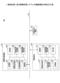
図4は、一実施形態に係る情報処理システムの機能構成を示す図である。
<Functional configuration>
FIG. 4 is a diagram showing a functional configuration of an information processing system according to an embodiment.
(情報処理装置の機能構成)
情報処理装置101は、例えば、図2のCPU201で所定のプログラムを実行することにより、通信部401、印刷制御部402、情報受信部403、診断部404、診断結果送信部405、接続情報提供部406、及び記憶部407等を実現している。なお、上記の各機能構成のうち、少なくとも一部は、ハードウェアによって実現されるものであっても良い。
(Functional configuration of information processing device)
For example, the
通信部401は、例えば、ネットワークI/F208等を用いて、情報処理装置101をネットワーク103に接続し、画像形成装置102、携帯端末104等の他の装置と通信を行なう。
The
印刷制御部402は、例えば、CPU201で実行されるプリンタドライバ等によって実現され、画像形成装置102が実行する印刷処理を制御する。例えば、印刷制御部402は、ユーザ105による印刷操作に応じて、印刷対象となるデータを画像形成装置102で印刷可能な印刷データに変換し、画像形成装置102に送信するともに、画像形成装置102に印刷処理の実行を指示する。なお、プリンタドライバは、画像形成装置102による印刷を制御するプログラムであり、例えば、画像形成装置102を提供するベンダー等によって提供される。
The
好ましくは、印刷制御部402は、画像形成装置102に印刷処理の実行を指示した後に、印刷処理に対応する論理プリンタの情報(例えば、プリンタアイコン名)を指定して、後述する診断ツールを起動する。
Preferably, after instructing the
ここで、論理プリンタとは、例えば、OSのプリンタフォルダ等に、プリンタアイコンとして表示される仮想的なプリンタであり、プリンタアイコンとも呼ばれる。例えば、ユーザ105は、1つの画像形成装置102に対して、設定情報(例えば、用紙サイズや向き、印刷品質等)が異なる複数の論理プリンタ(プリンタアイコン)を作成することができる。
Here, the logical printer is a virtual printer displayed as a printer icon in, for example, a printer folder of the OS, and is also called a printer icon. For example, the
情報受信部403は、例えば、CPU201で実行される診断ツール等によって実現され、印刷制御部402が、画像形成装置102に印刷処理の実行を指示した後に、携帯端末104から送信される画像形成装置102の識別情報を受信する。なお、診断ツールは、印刷処理のエラー原因を特定する診断処理を実行するプログラムであり、例えば、画像形成装置102を提供するベンダー等によって提供される。
The
診断部404は、例えば、CPU201で実行される診断ツール等によって実現される。診断部404は、印刷制御部402が印刷処理の実行を指示した画像形成装置102の情報と、携帯端末104から送信される画像形成装置102の識別情報とに基づいて、印刷処理のエラー原因を特定する診断処理を実行する。
The
なお、画像形成装置102の情報には、例えば、印刷制御部402が、診断ツールを起動するときに指定した論理プリンタの情報が含まれる。また、画像形成装置102の識別情報には、画像形成装置102と通信するためのアドレス情報(例えば、IPアドレス)が含まれる。また、診断部404が実行する診断処理には、論理プリンタが使用しているポートのIPアドレスと、画像形成装置102のIPアドレスとを比較する処理が含まれる。
Note that the information on the
図5は、一実施形態に係る診断情報の一例のイメージを示す図である。診断部404は、例えば、図5に示すような診断情報500を用いて、診断処理を実行しても良い。図5の例では、診断情報500には、項目として、「論理プリンタ、画像形成装置のIPアドレスの比較結果」、「通信可否」、「診断結果」等の情報が含まれる。
FIG. 5 is a diagram illustrating an example of diagnostic information according to an embodiment. The
「論理プリンタ、画像形成装置のIPアドレスの比較結果」は、論理プリンタ使用しているポートのIPアドレスと、画像形成装置102のIPアドレスとの比較結果を示している。「通信可否」は、情報処理装置101が、画像形成装置102の通信できるか否かの確認結果を示している。「診断結果」は、「論理プリンタ、画像形成装置のIPアドレスの比較結果」、及び「通信可否」に対応する診断結果を示している。
“Result of comparison of IP addresses of logical printer and image forming device” shows the result of comparing the IP address of the port used by the logical printer and the IP address of the
例えば、論理プリンタが使用しているポートのIPアドレスが「10.60.100.101」であり、画像形成装置102のIPアドレスが「10.60.100.101」である場合、「論理プリンタ、画像形成装置のIPアドレスの比較結果」は「一致」となる。また、この状態で、画像形成装置102と通信できない場合、「通信可否」は「不可」となり、「診断結果」は、「PCからプリンタへネットワーク接続できていません。」となる。
For example, if the IP address of the port used by the logical printer is "10.60.100.101" and the IP address of the
好ましくは、「診断結果」には、診断結果に対応する解決策が含まれる。例えば、診断結果「PCからプリンタへネットワーク接続できていません。」には、解決策「プリンタのLANケーブルが抜けていないか確認して下さい。」が含まれている。なお、図5において、「PC」は情報処理装置101の一例であり、「プリンタ」は画像形成装置102の一例である。
Preferably, the "diagnosis result" includes a solution corresponding to the diagnosis result. For example, the diagnosis result ``The network connection from the PC to the printer is not established.'' includes the solution ``Please check whether the LAN cable of the printer is disconnected.'' Note that in FIG. 5, “PC” is an example of the
また、例えば、論理プリンタが使用しているポートのIPアドレスが「10.60.100.101」であり、画像形成装置102のIPアドレスが「10.60.100.102」である場合、「論理プリンタ、画像形成装置のIPアドレスの比較結果」は「不一致」となる。この場合、「診断結果」は、「論理プリンタのポートの設定に誤りがあります。」となる。好ましくは、この「診断結果」には、解決策「プリンタアイコンのポートの設定を確認して下さい。」が含まれる。
For example, if the IP address of the port used by the logical printer is "10.60.100.101" and the IP address of the
なお、診断部404は、図5に示すような診断情報500に代えて、例えば、機械学習によって予め学習済の予測モデルに、「論理プリンタ、画像形成装置のIPアドレスの比較結果」、「通信可否」等の情報を入力して、診断結果を出力するもの等であっても良い。
Note that, instead of the
ここで、機械学習とは、コンピュータに人のような学習能力を獲得させるための技術であり、コンピュータが、データ識別等の判断に必要なアルゴリズムを、事前に取り込まれる学習データから自律的に生成して、新たなデータについてこれを適用して予測を行なう技術のことをいう。機械学習のための学習方法は、教師あり学習、教師なし学習、半教師学習、強化学習、深層学習のいずれかの方法でもよく、さらに、これらの学習方法を組み合わせた学習方法でもよく、機械学習のための学習方法は問わない。 Here, machine learning is a technology that allows computers to acquire human-like learning abilities, and computers autonomously generate algorithms necessary for decisions such as data identification from learning data that has been captured in advance. A technology that applies this to new data to make predictions. The learning method for machine learning may be supervised learning, unsupervised learning, semi-supervised learning, reinforcement learning, or deep learning, or it may be a learning method that combines these learning methods. It doesn't matter what learning method you use.
診断結果送信部405は、例えば、CPU201で実行される診断ツール等によって実現され、診断部404による診断結果を、通信部401を介して、携帯端末104に送信する。
The diagnostic
接続情報提供部406は、例えば、CPU201で実行される診断ツール等によって実現され、情報処理装置101と通信するための接続情報を、携帯端末104に提供する。一例として、接続情報提供部406は、ユーザ105による操作等に応じて、情報処理装置101と通信するための接続情報を表すQRコード(登録商標)等の二次元コードを、図2のディスプレイ206等に表示する。この接続情報には、例えば、情報処理装置101のIPアドレス等が含まれる。また、この接続情報には、例えば、情報処理装置101と通信するための認証情報(暗証番号、パスコード等)等、IPアドレス以外の情報が含まれていても良い。
The connection
記憶部407は、例えば、図2のCPU201で実行されるプログラム、及びHD204、HDDコントローラ205、RAM203等によって実現される。記憶部407は、例えば、前述した診断ツール、プリンタドライバ等のプログラム、及び診断情報500等の様々な情報を記憶する。
The
(携帯端末の機能構成)
携帯端末104は、例えば、図3のCPU301で所定のプログラム(アプリ)を実行することにより、通信部411、接続情報取得部412、受付部413、情報送信部414、診断結果表示部415、及び記憶部416等を実現している。なお、上記の各機能構成のうち、少なくとも一部は、ハードウェアによって実現されるものであっても良い。
(Functional configuration of mobile terminal)
For example, the
通信部401は、例えば、図3の遠距離通信回路311等を用いて、携帯端末104をネットワーク103に接続し、情報処理装置101等の他の装置と通信を行なう。
The
接続情報取得部412は、例えば、図3のCPU301が実行するアプリ等によって実現され、情報処理装置101の接続情報提供部406が提供する接続情報を取得する。例えば、接続情報取得部412は、図3のCMOSセンサ312、撮像素子I/F313等を用いて、接続情報提供部406が表示する二次元コードを撮影し、撮影した二次元コードを解析して、情報処理装置101の接続情報を取得する。
The connection
受付部413は、例えば、図3のCPU301が実行するアプリ等によって実現され、画像形成装置102の識別情報の入力を受け付ける。例えば、受付部413は、図3のディスプレイ317等に、画像形成装置102のIPアドレスを入力する入力画面を表示させて、タッチパネル320等を用いて、利用者によって入力されるIPアドレスを受け付ける。
The receiving
ただし、これに限られず、受付部413は、図3の近距離通信回路319を用いて、例えば、NFC等の近距離無線通信により、画像形成装置102、又は画像形成装置102に取付けられた無線タグ等から、画像形成装置102の識別情報を取得しても良い。
However, the present invention is not limited to this, and the
情報送信部414は、例えば、図3のCPU301が実行するアプリ等によって実現され、受付部413が受け付けた画像形成装置102の識別情報(IPアドレス等)を、通信部411を介して、情報処理装置101に送信する。
The
診断結果表示部415は、例えば、図3のCPU301が実行するアプリ等によって実現され、情報処理装置101から送信される診断結果に基づいて、診断結果の表示画面を、図3のディスプレイ317等の表示部に表示する。
The diagnosis
記憶部416は、例えば、図3のCPU301で実行されるプログラム、及びストレージデバイス304、RAM303等によって実現され、アプリ等のプログラム、及び様々な情報を記憶する。
The
画像形成装置102の機能構成は、従来の画像形成装置と同様で良いので、ここでは説明を省略する。
The functional configuration of the
<処理の流れ>
続いて、情報処理システム100が実行する情報処理方法の処理の流れについて説明する。
<Processing flow>
Next, the flow of processing of the information processing method executed by the
[第1の実施形態]
図6は、第1の実施形態に係る情報処理システムの処理の例を示すシーケンス図である。この処理は、ユーザ105が、情報処理装置101に対して印刷操作を行ない、画像形成装置102による印刷処理に失敗したときに、情報処理システム100が実行する処理の一例を示している。
[First embodiment]
FIG. 6 is a sequence diagram illustrating an example of processing of the information processing system according to the first embodiment. This process is an example of a process executed by the
ユーザ105は、携帯端末104に、情報処理装置101と通信するための接続情報が未登録である場合、例えば、ステップS601~S605に示す接続情報の登録処理600を実行した後に、ステップS611の処理を実行する。一方、ユーザ105は、携帯端末104に、情報処理装置101と通信するための接続情報が登録済である場合、例えば、接続情報の登録処理600を省略して、ステップS611の処理を実行する。
If the connection information for communicating with the
ステップS601において、ユーザ105は、情報処理装置101に対して、接続情報の表示操作を行なう。
In step S601, the
ステップS602において、情報処理装置101の接続情報提供部406は、接続情報の表示操作を受け付けると、例えば、図7(A)に示すような接続情報の提供画面710を、ディスプレイ206等の表示部に表示する。
In step S602, upon receiving the connection information display operation, the connection
図7(A)は、接続情報提供部406が表示する接続情報の提供画面710の例を示している。図7(A)の例では、接続情報の提供画面710には、情報処理装置101と通信するための接続情報をコード化した二次元コード711が表示されている。なお、接続情報には、前述したように、例えば、情報処理装置101のIPアドレス等が含まれる。また、接続情報には、例えば、情報処理装置101と通信するための認証情報(暗証番号、パスコード等)等、IPアドレス以外の情報が含まれていても良い。
FIG. 7A shows an example of a connection
ステップS603において、ユーザ105は、携帯端末104に対して、接続情報の取得操作を行なう。
In step S603, the
ステップS604において、携帯端末104の接続情報取得部412は、接続情報の取得操作を受け付けると、例えば、図7(B)に示すような接続情報の取得画面720を、ディスプレイ317等の表示部に表示する。
In step S604, upon receiving the connection information acquisition operation, the connection
図7(B)は、接続情報取得部412が表示する接続情報の取得画面720の一例を示している。図7(B)の例では、接続情報の取得画面720には、CMOSセンサ312、撮像素子I/F313等を用いて撮影した撮影画像721と、二次元コード711の読み取りを促すメッセージ722が表示されている。例えば、ユーザ105が、撮影画像721に、二次元コード711が映るように、携帯端末104の位置を調整すると、ステップS605の処理が実行される。
FIG. 7B shows an example of a connection
ステップS605において、接続情報取得部412は、撮影画像721に含まれる二次元コード711を解析して、情報処理装置101と通信するための接続情報を取得する。
In step S605, the connection
ステップS606において、接続情報取得部412は、例えば、図7(C)に示すような登録結果の表示画面730を、ディスプレイ317等の表示部に表示する。
In step S606, the connection
なお、ステップS601~S606に示した接続情報の登録処理600は一例である。例えば、接続情報の登録処理は、情報処理装置101が表示したIPアドレス等の文字列を、ユーザ105が、携帯端末104に入力するものであっても良いし、携帯端末104が、NFC等の近距離無線通信で接続情報を取得するもの等であっても良い。
Note that the connection
ステップS611において、ユーザ105が、情報処理装置101に対して印刷操作を行なうものとする。例えば、ユーザ105は、オフィスソフト等のアプリケーションプログラムから、画像形成装置102を指定して、印刷を行なう。
In step S611, it is assumed that the
ステップS612において、情報処理装置101の印刷制御部402は、画像形成装置102に印刷処理の実行を指示する。例えば、印刷制御部402は、ユーザ105による印刷操作に応じてアプリケーションプログラムから出力される印刷対象データを印刷データに変換する。また、印刷制御部402は、変換した印刷データを画像形成装置102に送信するとともに、画像形成装置102に印刷処理の実行を指示する。
In step S612, the
ステップS613において、ユーザ105は、画像形成装置102が設置されている場所に移動して、印刷結果を確認する。ここで、正常に印刷が行なわれていないこと(印刷失敗)が確認された場合、ステップS614以降の処理を実行する。
In step S613, the
ステップS614において、ユーザ105は、携帯端末104に対して、IPアドレスを設定する設定画面の表示操作を行なう。
In step S614, the
ステップS615において、携帯端末104の情報送信部414は、ユーザ105による設定画面の表示操作を受け付けると、例えば、図8(A)に示すような設定画面810を、ディスプレイ317等の表示部に表示する。
In step S615, upon receiving the setting screen display operation from the
図8(A)は、携帯端末104の情報送信部414が表示する設定画面810の一例を示している。図8(A)の例では、設定画面810には、情報処理装置101のIPアドレスを設定する設定欄811、及び画像形成装置102のIPアドレスを設定する設定欄812が表示されている。なお、IPアドレスの設定画面810において「PC」は、情報処理装置101に対応しており、「プリンタ」は、画像形成装置102に対応している。
FIG. 8A shows an example of a
好適な一例として、情報処理装置101のIPアドレスを設定する設定欄811は、プルダウンメニューにより、携帯端末104に登録済の情報処理装置101のIPアドレスを選択可能に表示しても良い。同様に、画像形成装置102のIPアドレスを設定する設定欄812は、携帯端末104に登録済の画像形成装置102のIPアドレスを選択可能に表示しても良い。
As a preferable example, the
ステップS616において、ユーザ105は、例えば、図8(A)に示すような設定画面810に対して、IPアドレスの設定操作を行なう。例えば、ユーザ105は、情報処理装置101のIPアドレスを設定する設定欄811、画像形成装置102のIPアドレスを設定する設定欄812にIPアドレスを設定し、診断ボタン813を選択する。
In step S616, the
ステップS617において、携帯端末104の情報送信部414は、IPアドレスの設定操作を受け付けると、情報処理装置101に、画像形成装置102のIPアドレスを送信する。
In step S<b>617 , upon receiving the IP address setting operation, the
なお、ステップS614~S617において、携帯端末104の情報送信部414は、IPアドレス以外の情報(例えば、画像形成装置の機種情報等)をさらに取得して、情報処理装置101に送信しても良い。
Note that in steps S614 to S617, the
ステップS618において、情報処理装置101の診断部404は、印刷処理に対応する論理プリンタの情報と、携帯端末104から受信した画像形成装置102のIPアドレス(識別情報)とに基づいて、診断処理を実行する。
In step S618, the
一例として、診断部404は、論理プリンタが使用しているポートのIPアドレス、画像形成装置102のIPアドレス、及び図5に示すような診断情報500とを用いて、印刷処理のエラー原因を特定する診断結果を取得する。例えば、論理プリンタが使用しているポートのIPアドレスが「10.60.100.101」、画像形成装置102のIPアドレスが「10.60.100.101」であり、かつ画像形成装置102と通信できないものとする。この場合、診断部404は、図5に示すような診断情報500から、診断結果「PCからプリンタへネットワーク接続できていません。プリンタのLANケーブルが抜けていないか確認して下さい。」を取得する。
As an example, the
ステップS619において、情報処理装置101の診断結果送信部405は、診断部404による診断結果を、携帯端末104に送信する。
In step S619, the diagnosis
ステップS620において、携帯端末104の診断結果表示部415は、情報処理装置101から受信した診断結果を表示する。例えば、診断結果表示部415は、図8(B)に示すような診断結果の表示画面820を、ディスプレイ317等の表示部に表示する。
In step S620, the diagnosis
図8(B)は、診断結果表示部415が表示する診断結果の表示画面820の一例を示している。図8(B)の例では、診断結果の表示画面820には、診断部404による診断結果の一例として、エラー原因821と、エラー原因821に対応する解決策822とが表示されている。ただし、これに限られず、診断結果の表示画面820には、エラー原因821、及びエラー原因821に対応する解決策822のうち、少なくとも1つが含まれていれば良い。
FIG. 8B shows an example of a diagnosis result display screen 820 displayed by the diagnosis
上記の処理により、印刷に失敗したときに、ユーザ105が、情報処理装置101と画像形成装置102との間を往復して情報や状態の収集を行なわなくても、印刷処理のエラー原因821を特定できるようになる。また、情報処理システム100は、印刷処理のエラー原因821に対応する解決策822を、ユーザ105に提供することができるので、ユーザ105は、解決策822を参照して問題を解消することができるようになる。
With the above processing, when printing fails, the
[第2の実施形態]
第1の実施形態では、例えば、図6のステップS619、S620において、携帯端末140は、情報処理装置101から送信される診断結果を表示していた。ただし、これに限られず、診断結果の表示画面820に表示する情報のうち、少なくとも一部を携帯端末140が作成しても良い。
[Second embodiment]
In the first embodiment, for example, in steps S619 and S620 in FIG. 6, the mobile terminal 140 displays the diagnosis result transmitted from the
図9(A)は、第2の実施形態に係る情報処理装置101が管理する診断情報910の一例のイメージを示している。図9(A)の例では、診断情報910は、図5に示した一実施形態に係る診断情報500に含まれる「診断結果」に代えて、「エラーコード」が含まれている。なお、「エラーコード」は、診断部404による診断結果の別の一例である。
FIG. 9A shows an image of an example of
図9(B)は、第2の実施形態に係る携帯端末104が管理する診断情報920の一例のイメージを示している。図9(B)の例では、診断情報920には、「エラーコード」の各々に対応する、「診断結果」として、エラー原因、及びエラー原因に対応する解決策を示す文字列が記憶されている。これにより、携帯端末104は、情報処理装置101から送信されるエラーコードに基づいて、例えば、図8(B)に示すような診断結果の表示画面820を作成することができる。
FIG. 9B shows an image of an example of
<処理の流れ>
図10は、第2の実施形態に係る情報処理システムの処理の例を示すシーケンス図である。なお、図10に示す処理のうち、ステップS611~S615の処理は、図6で説明した第1の実施形態に係る情報処理システムの処理と同様なので、ここでは、第1の実施形態との相違点を中心に説明する。
<Processing flow>
FIG. 10 is a sequence diagram illustrating an example of processing of the information processing system according to the second embodiment. Note that among the processes shown in FIG. 10, the processes in steps S611 to S615 are similar to the processes of the information processing system according to the first embodiment described in FIG. 6, so the differences from the first embodiment will be explained here. I will mainly explain the points.
ステップS1001において、情報処理装置101の診断部404は、印刷処理に対応する論理プリンタの情報と、携帯端末104から受信した画像形成装置102のIPアドレス(識別情報)とに基づいて、診断処理を実行する。ここでは、診断部404は、論理プリンタが使用しているポートのIPアドレス、画像形成装置102のIPアドレス、及び図9(A)に示すような診断情報910を用いて、印刷処理のエラー原因に対応するエラーコードを取得する。なお、エラーコードは、例えば、印刷処理のエラー原因等を識別する識別情報の一例である。
In step S<b>1001 , the
ステップS1002において、情報処理装置101の診断結果送信部405は、診断部404による診断結果の一例であるエラーコードを、携帯端末104に送信する。
In step S<b>1002 , the diagnosis
ステップS1003において、携帯端末104の診断結果表示部415は、情報処理装置101から送信されたエラーコードに基づいて、例えば、図8(B)に示すような診断結果の表示画面820を作成する。例えば、診断結果表示部415は、図9(B)に示されるような診断情報920から、エラーコードに対応する診断結果を示す文字列を取得して、取得した文字列を含む診断結果の表示画面820を作成する。
In step S1003, the diagnosis
ステップS1004において、診断結果表示部415は、作成した診断結果の表示画面820を、ディスプレイ317等の表示部に表示する。
In step S1004, the diagnosis
このように、携帯端末104の診断結果表示部415は、情報処理装置101から送信されるエラーコード(診断結果の別の一例)等に基づいて、診断結果の表示画面820を作成しても良い。
In this way, the diagnosis
以上、本発明の各実施形態によれば、印刷に失敗したときに、ユーザが、情報処理装置と画像形成装置との間を往復して情報や状態の収集を行なわなくても、印刷処理のエラー原因を特定可能な情報処理システムを提供することができる。 As described above, according to each embodiment of the present invention, when printing fails, the user does not have to go back and forth between the information processing device and the image forming device to collect information and status. An information processing system that can identify the cause of an error can be provided.
<補足>
上記で説明した各実施形態の各機能は、一又は複数の処理回路によって実現することが可能である。ここで、本明細書における「処理回路」とは、電子回路により実装されるプロセッサのようにソフトウェアによって各機能を実行するようプログラミングされたプロセッサや、上記で説明した各機能を実行するよう設計されたASIC(Application Specific Integrated Circuit)、DSP(digital signal processor)、FPGA(field programmable gate array)や従来の回路モジュール等のデバイスを含むものとする。
<Supplement>
Each function of each embodiment described above can be realized by one or more processing circuits. Here, the term "processing circuit" as used herein refers to a processor programmed to execute each function by software, such as a processor implemented by an electronic circuit, or a processor designed to execute each function explained above. This includes devices such as ASICs (Application Specific Integrated Circuits), DSPs (Digital Signal Processors), FPGAs (Field Programmable Gate Arrays), and conventional circuit modules.
また、実施例に記載された装置群は、本明細書に開示された実施形態を実施するための複数のコンピューティング環境のうちの1つを示すものに過ぎない。ある実施形態では、情報処理装置101は、サーバクラスタといった複数のコンピューティングデバイスを含む。複数のコンピューティングデバイスは、ネットワークや共有メモリなどを含む任意のタイプの通信リンクを介して互いに通信するように構成されており、本明細書に開示された処理を実施する。同様に、携帯端末104は、互いに通信するように構成された複数のコンピューティングデバイスを含むことができる。
Additionally, the devices described in the examples are merely illustrative of one of multiple computing environments for implementing the embodiments disclosed herein. In some embodiments,
さらに、情報処理装置101及び携帯端末104は、開示された処理ステップ、例えば図6に示す処理を様々な組合せで共有するように構成できる。例えば、情報処理装置101が備える各機能構成によって実行されるプロセスは、携帯端末104によって実行され得る。同様に、携帯端末104が備える各機能構成によって実行されるプロセスは、情報処理装置101によって実行することができる。また、情報処理装置101の各機能構成は、1つのサーバ装置にまとめられていても良いし、複数の装置に分けられていても良い。
Furthermore, the
100 情報処理システム
101 情報処理装置
102 画像形成装置
104 携帯端末
403 情報受信部
404 診断部
405 診断結果送信部
406 接続情報提供部
412 接続情報取得部
413 受付部
414 情報送信部
415 診断結果表示部
100
Claims (10)
画像形成装置に前記印刷処理の実行を指示した後に、携帯端末から送信される前記画像形成装置の識別情報を受信する情報受信部と、
前記画像形成装置の識別情報と、前記印刷処理の実行を指示した前記画像形成装置の情報とに基づいて、前記印刷処理のエラー原因を特定する診断処理を実行する診断部と、
前記診断処理の診断結果を前記携帯端末に送信する診断結果送信部と、
前記情報処理装置と通信するための接続情報を、前記携帯端末に提供する接続情報提供部と、
を有する、情報処理装置。 An information processing device that controls print processing,
an information receiving unit that receives identification information of the image forming apparatus transmitted from a mobile terminal after instructing the image forming apparatus to execute the printing process;
a diagnostic unit that executes a diagnostic process to identify a cause of an error in the print process based on identification information of the image forming apparatus and information of the image forming apparatus that has instructed execution of the print process;
a diagnosis result transmitter that transmits the diagnosis result of the diagnosis process to the mobile terminal;
a connection information providing unit that provides the mobile terminal with connection information for communicating with the information processing device;
An information processing device having:
前記情報処理装置と通信可能な携帯端末と、
を含む情報処理システムであって、
前記携帯端末は、
画像形成装置の識別情報の入力を受け付ける受付部と、
前記画像形成装置の識別情報を前記情報処理装置に送信する情報送信部と、
前記情報処理装置から送信される診断結果に基づいて、診断結果の表示画面を表示する診断結果表示部と、
を有する、情報処理システム。 The information processing device according to any one of claims 1 to 4 ,
a mobile terminal capable of communicating with the information processing device;
An information processing system comprising:
The mobile terminal is
a reception unit that receives input of identification information of the image forming apparatus;
an information transmitter that transmits identification information of the image forming apparatus to the information processing apparatus;
a diagnosis result display unit that displays a diagnosis result display screen based on the diagnosis result transmitted from the information processing device;
An information processing system with
画像形成装置に前記印刷処理の実行を指示した後に、携帯端末から送信される前記画像形成装置の識別情報を受信する情報受信部と、an information receiving unit that receives identification information of the image forming apparatus transmitted from a mobile terminal after instructing the image forming apparatus to execute the printing process;
前記画像形成装置の識別情報と、前記印刷処理の実行を指示した前記画像形成装置の情報とに基づいて、前記印刷処理のエラー原因を特定する診断処理を実行する診断部と、a diagnostic unit that executes a diagnostic process to identify a cause of an error in the print process based on identification information of the image forming apparatus and information of the image forming apparatus that has instructed execution of the print process;
前記診断処理の診断結果を前記携帯端末に送信する診断結果送信部と、a diagnosis result transmitter that transmits the diagnosis result of the diagnosis process to the mobile terminal;
を有し、has
前記画像形成装置の識別情報は、前記画像形成装置と通信するためのアドレス情報を含み、The identification information of the image forming apparatus includes address information for communicating with the image forming apparatus,
前記画像形成装置の情報は、前記印刷処理に対応する論理プリンタの情報を含む、The information on the image forming apparatus includes information on a logical printer corresponding to the print process.
情報処理システム。Information processing system.
前記情報処理装置は、
画像形成装置に前記印刷処理の実行を指示した後に、携帯端末から送信される前記画像形成装置の識別情報を受信する情報受信部と、
前記画像形成装置の識別情報と、前記印刷処理の実行を指示した前記画像形成装置の情報とに基づいて、前記印刷処理のエラー原因を特定する診断処理を実行する診断部と、
前記診断処理の診断結果を前記携帯端末に送信する診断結果送信部と、
前記情報処理装置と通信するための接続情報を、前記携帯端末に提供する接続情報提供部と、
を有し、
前記携帯端末は、
前記画像形成装置の識別情報を前記情報処理装置に送信する情報送信部と、
前記情報処理装置から送信される前記診断結果に基づいて、診断結果の表示画面を表示する診断結果表示部と、
を有する、
情報処理システム。 An information processing system including an information processing device that controls print processing and a mobile terminal that can communicate with the information processing device,
The information processing device includes:
an information receiving unit that receives identification information of the image forming apparatus transmitted from a mobile terminal after instructing the image forming apparatus to execute the printing process;
a diagnostic unit that executes a diagnostic process to identify a cause of an error in the print process based on identification information of the image forming apparatus and information of the image forming apparatus that has instructed execution of the print process;
a diagnosis result transmitter that transmits the diagnosis result of the diagnosis process to the mobile terminal;
a connection information providing unit that provides the mobile terminal with connection information for communicating with the information processing device;
has
The mobile terminal is
an information transmitter that transmits identification information of the image forming apparatus to the information processing apparatus;
a diagnosis result display unit that displays a diagnosis result display screen based on the diagnosis result transmitted from the information processing device;
has,
Information processing system.
画像形成装置に前記印刷処理の実行を指示した後に、携帯端末から送信される前記画像形成装置の識別情報を受信する処理と、
前記画像形成装置の識別情報と、前記印刷処理の実行を指示した前記画像形成装置の情報とに基づいて、前記印刷処理のエラー原因を特定する診断処理と、
前記診断処理の診断結果を前記携帯端末に送信する処理と、
前記情報処理装置と通信するための接続情報を、前記携帯端末に提供する処理と、
を実行させる、プログラム。 In the information processing device that controls the printing process,
after instructing the image forming apparatus to execute the printing process, receiving identification information of the image forming apparatus transmitted from a mobile terminal;
Diagnosis processing that identifies a cause of an error in the printing process based on identification information of the image forming apparatus and information of the image forming apparatus that has instructed execution of the printing process;
a process of transmitting the diagnosis result of the diagnosis process to the mobile terminal;
a process of providing the mobile terminal with connection information for communicating with the information processing device;
A program to run.
Priority Applications (1)
| Application Number | Priority Date | Filing Date | Title |
|---|---|---|---|
| JP2019214514A JP7358948B2 (en) | 2019-11-27 | 2019-11-27 | Information processing device, information processing system, and program |
Applications Claiming Priority (1)
| Application Number | Priority Date | Filing Date | Title |
|---|---|---|---|
| JP2019214514A JP7358948B2 (en) | 2019-11-27 | 2019-11-27 | Information processing device, information processing system, and program |
Publications (2)
| Publication Number | Publication Date |
|---|---|
| JP2021086374A JP2021086374A (en) | 2021-06-03 |
| JP7358948B2 true JP7358948B2 (en) | 2023-10-11 |
Family
ID=76087765
Family Applications (1)
| Application Number | Title | Priority Date | Filing Date |
|---|---|---|---|
| JP2019214514A Active JP7358948B2 (en) | 2019-11-27 | 2019-11-27 | Information processing device, information processing system, and program |
Country Status (1)
| Country | Link |
|---|---|
| JP (1) | JP7358948B2 (en) |
Citations (8)
| Publication number | Priority date | Publication date | Assignee | Title |
|---|---|---|---|---|
| JP2002073440A (en) | 2000-09-01 | 2002-03-12 | Ricoh Co Ltd | Image formation device management system, communication control device used therefor and identification information management method |
| JP2005165773A (en) | 2003-12-03 | 2005-06-23 | Canon Inc | Information processor, information processing method, information processing program, and storage medium |
| JP2015191473A (en) | 2014-03-28 | 2015-11-02 | 船井電機株式会社 | Image forming device management system and image forming device |
| JP2015203967A (en) | 2014-04-14 | 2015-11-16 | 京セラドキュメントソリューションズ株式会社 | Image formation system, portable terminal and information processing device |
| JP2016173761A (en) | 2015-03-17 | 2016-09-29 | 株式会社リコー | Information processing apparatus, distributed processing method, and storage medium |
| JP2016177781A (en) | 2015-03-20 | 2016-10-06 | 株式会社リコー | Information processing system, information processing device, and program |
| JP2016201670A (en) | 2015-04-09 | 2016-12-01 | キヤノン株式会社 | Communication device, control method, program of communication device |
| JP2017072878A (en) | 2015-10-05 | 2017-04-13 | 京セラドキュメントソリューションズ株式会社 | Image forming system |
-
2019
- 2019-11-27 JP JP2019214514A patent/JP7358948B2/en active Active
Patent Citations (8)
| Publication number | Priority date | Publication date | Assignee | Title |
|---|---|---|---|---|
| JP2002073440A (en) | 2000-09-01 | 2002-03-12 | Ricoh Co Ltd | Image formation device management system, communication control device used therefor and identification information management method |
| JP2005165773A (en) | 2003-12-03 | 2005-06-23 | Canon Inc | Information processor, information processing method, information processing program, and storage medium |
| JP2015191473A (en) | 2014-03-28 | 2015-11-02 | 船井電機株式会社 | Image forming device management system and image forming device |
| JP2015203967A (en) | 2014-04-14 | 2015-11-16 | 京セラドキュメントソリューションズ株式会社 | Image formation system, portable terminal and information processing device |
| JP2016173761A (en) | 2015-03-17 | 2016-09-29 | 株式会社リコー | Information processing apparatus, distributed processing method, and storage medium |
| JP2016177781A (en) | 2015-03-20 | 2016-10-06 | 株式会社リコー | Information processing system, information processing device, and program |
| JP2016201670A (en) | 2015-04-09 | 2016-12-01 | キヤノン株式会社 | Communication device, control method, program of communication device |
| JP2017072878A (en) | 2015-10-05 | 2017-04-13 | 京セラドキュメントソリューションズ株式会社 | Image forming system |
Also Published As
| Publication number | Publication date |
|---|---|
| JP2021086374A (en) | 2021-06-03 |
Similar Documents
| Publication | Publication Date | Title |
|---|---|---|
| TWI469042B (en) | Authenticating printers prior to pairing with portable electronic devices | |
| JP5846157B2 (en) | PRINT SYSTEM, CONVENIENCE INFORMATION GENERATION DEVICE, CONVENIENCE INFORMATION GENERATION METHOD, AND CONVENIENCE INFORMATION GENERATION PROGRAM | |
| US8351060B2 (en) | Method of and apparatus to print image directly | |
| JP6992293B2 (en) | Shared terminals, communication systems, image transmission methods, and programs | |
| CN102778948B (en) | Information processor and information processing method | |
| KR20120134913A (en) | Method and apparatus for developing application of image forming apparatus | |
| US10007404B2 (en) | Terminal apparatus, program, method of calling function, and information processing system | |
| US20200267268A1 (en) | Image forming apparatus, display control method, and recording medium | |
| US11762612B2 (en) | Information processing apparatus, information processing system, and information processing method for managing authentication information across multiple information processing devices, information processing apparatuses, and information processing systems | |
| JP6919432B2 (en) | Shared terminals, communication systems, communication methods, and programs | |
| JP2020136829A (en) | Image forming apparatus, information processing method and program | |
| JP7358948B2 (en) | Information processing device, information processing system, and program | |
| KR20170070649A (en) | Image forming apparuatus, cloud server, image forming system, and method for setting of connection with image forming apparatus | |
| US11249708B2 (en) | Image forming apparatus, image forming method and recording medium | |
| US11509560B2 (en) | Information processing apparatus, communication system, and information processing method | |
| JP6822341B2 (en) | Shared terminals, communication systems, image transmission methods, and programs | |
| JP6274186B2 (en) | Image forming apparatus, image forming system, and program | |
| US20240147004A1 (en) | Terminal device, information processing method, and non-transitory recording medium | |
| JP7318401B2 (en) | Cooperative processor, method and program | |
| JP7392399B2 (en) | Information processing device, system, information processing method, and program | |
| JP7439570B2 (en) | Information processing device, control method, and program | |
| US11871231B2 (en) | Apparatus management system, management target apparatus, and management method | |
| JP2018142310A (en) | Communication terminal, communication system, communication method, and program | |
| JP7459659B2 (en) | Information processing device, communication system and information processing method | |
| JP7139991B2 (en) | Information processing system, method, and information processing device |
Legal Events
| Date | Code | Title | Description |
|---|---|---|---|
| A621 | Written request for application examination |
Free format text: JAPANESE INTERMEDIATE CODE: A621 Effective date: 20220914 |
|
| A977 | Report on retrieval |
Free format text: JAPANESE INTERMEDIATE CODE: A971007 Effective date: 20230529 |
|
| A131 | Notification of reasons for refusal |
Free format text: JAPANESE INTERMEDIATE CODE: A131 Effective date: 20230620 |
|
| A521 | Request for written amendment filed |
Free format text: JAPANESE INTERMEDIATE CODE: A523 Effective date: 20230815 |
|
| TRDD | Decision of grant or rejection written | ||
| A01 | Written decision to grant a patent or to grant a registration (utility model) |
Free format text: JAPANESE INTERMEDIATE CODE: A01 Effective date: 20230829 |
|
| A61 | First payment of annual fees (during grant procedure) |
Free format text: JAPANESE INTERMEDIATE CODE: A61 Effective date: 20230911 |
|
| R151 | Written notification of patent or utility model registration |
Ref document number: 7358948 Country of ref document: JP Free format text: JAPANESE INTERMEDIATE CODE: R151 |