JP7356980B2 - Devices, systems and methods for interacting with vascular images - Google Patents
Devices, systems and methods for interacting with vascular images Download PDFInfo
- Publication number
- JP7356980B2 JP7356980B2 JP2020534311A JP2020534311A JP7356980B2 JP 7356980 B2 JP7356980 B2 JP 7356980B2 JP 2020534311 A JP2020534311 A JP 2020534311A JP 2020534311 A JP2020534311 A JP 2020534311A JP 7356980 B2 JP7356980 B2 JP 7356980B2
- Authority
- JP
- Japan
- Prior art keywords
- blood vessel
- image
- contour
- processing unit
- vessel image
- Prior art date
- Legal status (The legal status is an assumption and is not a legal conclusion. Google has not performed a legal analysis and makes no representation as to the accuracy of the status listed.)
- Active
Links
Images


Classifications
-
- G—PHYSICS
- G06—COMPUTING; CALCULATING OR COUNTING
- G06T—IMAGE DATA PROCESSING OR GENERATION, IN GENERAL
- G06T7/00—Image analysis
- G06T7/10—Segmentation; Edge detection
- G06T7/12—Edge-based segmentation
-
- G—PHYSICS
- G06—COMPUTING; CALCULATING OR COUNTING
- G06F—ELECTRIC DIGITAL DATA PROCESSING
- G06F3/00—Input arrangements for transferring data to be processed into a form capable of being handled by the computer; Output arrangements for transferring data from processing unit to output unit, e.g. interface arrangements
- G06F3/01—Input arrangements or combined input and output arrangements for interaction between user and computer
- G06F3/048—Interaction techniques based on graphical user interfaces [GUI]
- G06F3/0484—Interaction techniques based on graphical user interfaces [GUI] for the control of specific functions or operations, e.g. selecting or manipulating an object, an image or a displayed text element, setting a parameter value or selecting a range
- G06F3/04845—Interaction techniques based on graphical user interfaces [GUI] for the control of specific functions or operations, e.g. selecting or manipulating an object, an image or a displayed text element, setting a parameter value or selecting a range for image manipulation, e.g. dragging, rotation, expansion or change of colour
-
- G—PHYSICS
- G06—COMPUTING; CALCULATING OR COUNTING
- G06F—ELECTRIC DIGITAL DATA PROCESSING
- G06F3/00—Input arrangements for transferring data to be processed into a form capable of being handled by the computer; Output arrangements for transferring data from processing unit to output unit, e.g. interface arrangements
- G06F3/01—Input arrangements or combined input and output arrangements for interaction between user and computer
- G06F3/048—Interaction techniques based on graphical user interfaces [GUI]
- G06F3/0487—Interaction techniques based on graphical user interfaces [GUI] using specific features provided by the input device, e.g. functions controlled by the rotation of a mouse with dual sensing arrangements, or of the nature of the input device, e.g. tap gestures based on pressure sensed by a digitiser
- G06F3/0488—Interaction techniques based on graphical user interfaces [GUI] using specific features provided by the input device, e.g. functions controlled by the rotation of a mouse with dual sensing arrangements, or of the nature of the input device, e.g. tap gestures based on pressure sensed by a digitiser using a touch-screen or digitiser, e.g. input of commands through traced gestures
-
- G—PHYSICS
- G06—COMPUTING; CALCULATING OR COUNTING
- G06T—IMAGE DATA PROCESSING OR GENERATION, IN GENERAL
- G06T7/00—Image analysis
- G06T7/10—Segmentation; Edge detection
- G06T7/13—Edge detection
-
- G—PHYSICS
- G06—COMPUTING; CALCULATING OR COUNTING
- G06T—IMAGE DATA PROCESSING OR GENERATION, IN GENERAL
- G06T7/00—Image analysis
- G06T7/10—Segmentation; Edge detection
- G06T7/149—Segmentation; Edge detection involving deformable models, e.g. active contour models
-
- G—PHYSICS
- G06—COMPUTING; CALCULATING OR COUNTING
- G06T—IMAGE DATA PROCESSING OR GENERATION, IN GENERAL
- G06T7/00—Image analysis
- G06T7/10—Segmentation; Edge detection
- G06T7/187—Segmentation; Edge detection involving region growing; involving region merging; involving connected component labelling
-
- G—PHYSICS
- G06—COMPUTING; CALCULATING OR COUNTING
- G06F—ELECTRIC DIGITAL DATA PROCESSING
- G06F3/00—Input arrangements for transferring data to be processed into a form capable of being handled by the computer; Output arrangements for transferring data from processing unit to output unit, e.g. interface arrangements
- G06F3/01—Input arrangements or combined input and output arrangements for interaction between user and computer
- G06F3/03—Arrangements for converting the position or the displacement of a member into a coded form
- G06F3/033—Pointing devices displaced or positioned by the user, e.g. mice, trackballs, pens or joysticks; Accessories therefor
- G06F3/0354—Pointing devices displaced or positioned by the user, e.g. mice, trackballs, pens or joysticks; Accessories therefor with detection of 2D relative movements between the device, or an operating part thereof, and a plane or surface, e.g. 2D mice, trackballs, pens or pucks
- G06F3/03543—Mice or pucks
-
- G—PHYSICS
- G06—COMPUTING; CALCULATING OR COUNTING
- G06F—ELECTRIC DIGITAL DATA PROCESSING
- G06F3/00—Input arrangements for transferring data to be processed into a form capable of being handled by the computer; Output arrangements for transferring data from processing unit to output unit, e.g. interface arrangements
- G06F3/01—Input arrangements or combined input and output arrangements for interaction between user and computer
- G06F3/03—Arrangements for converting the position or the displacement of a member into a coded form
- G06F3/033—Pointing devices displaced or positioned by the user, e.g. mice, trackballs, pens or joysticks; Accessories therefor
- G06F3/0354—Pointing devices displaced or positioned by the user, e.g. mice, trackballs, pens or joysticks; Accessories therefor with detection of 2D relative movements between the device, or an operating part thereof, and a plane or surface, e.g. 2D mice, trackballs, pens or pucks
- G06F3/03545—Pens or stylus
-
- G—PHYSICS
- G06—COMPUTING; CALCULATING OR COUNTING
- G06T—IMAGE DATA PROCESSING OR GENERATION, IN GENERAL
- G06T2200/00—Indexing scheme for image data processing or generation, in general
- G06T2200/04—Indexing scheme for image data processing or generation, in general involving 3D image data
-
- G—PHYSICS
- G06—COMPUTING; CALCULATING OR COUNTING
- G06T—IMAGE DATA PROCESSING OR GENERATION, IN GENERAL
- G06T2200/00—Indexing scheme for image data processing or generation, in general
- G06T2200/24—Indexing scheme for image data processing or generation, in general involving graphical user interfaces [GUIs]
-
- G—PHYSICS
- G06—COMPUTING; CALCULATING OR COUNTING
- G06T—IMAGE DATA PROCESSING OR GENERATION, IN GENERAL
- G06T2207/00—Indexing scheme for image analysis or image enhancement
- G06T2207/10—Image acquisition modality
- G06T2207/10072—Tomographic images
- G06T2207/10081—Computed x-ray tomography [CT]
-
- G—PHYSICS
- G06—COMPUTING; CALCULATING OR COUNTING
- G06T—IMAGE DATA PROCESSING OR GENERATION, IN GENERAL
- G06T2207/00—Indexing scheme for image analysis or image enhancement
- G06T2207/10—Image acquisition modality
- G06T2207/10072—Tomographic images
- G06T2207/10088—Magnetic resonance imaging [MRI]
-
- G—PHYSICS
- G06—COMPUTING; CALCULATING OR COUNTING
- G06T—IMAGE DATA PROCESSING OR GENERATION, IN GENERAL
- G06T2207/00—Indexing scheme for image analysis or image enhancement
- G06T2207/10—Image acquisition modality
- G06T2207/10072—Tomographic images
- G06T2207/10104—Positron emission tomography [PET]
-
- G—PHYSICS
- G06—COMPUTING; CALCULATING OR COUNTING
- G06T—IMAGE DATA PROCESSING OR GENERATION, IN GENERAL
- G06T2207/00—Indexing scheme for image analysis or image enhancement
- G06T2207/10—Image acquisition modality
- G06T2207/10072—Tomographic images
- G06T2207/10108—Single photon emission computed tomography [SPECT]
-
- G—PHYSICS
- G06—COMPUTING; CALCULATING OR COUNTING
- G06T—IMAGE DATA PROCESSING OR GENERATION, IN GENERAL
- G06T2207/00—Indexing scheme for image analysis or image enhancement
- G06T2207/10—Image acquisition modality
- G06T2207/10116—X-ray image
-
- G—PHYSICS
- G06—COMPUTING; CALCULATING OR COUNTING
- G06T—IMAGE DATA PROCESSING OR GENERATION, IN GENERAL
- G06T2207/00—Indexing scheme for image analysis or image enhancement
- G06T2207/20—Special algorithmic details
- G06T2207/20092—Interactive image processing based on input by user
-
- G—PHYSICS
- G06—COMPUTING; CALCULATING OR COUNTING
- G06T—IMAGE DATA PROCESSING OR GENERATION, IN GENERAL
- G06T2207/00—Indexing scheme for image analysis or image enhancement
- G06T2207/30—Subject of image; Context of image processing
- G06T2207/30004—Biomedical image processing
- G06T2207/30101—Blood vessel; Artery; Vein; Vascular
Landscapes
- Engineering & Computer Science (AREA)
- Theoretical Computer Science (AREA)
- Physics & Mathematics (AREA)
- General Physics & Mathematics (AREA)
- General Engineering & Computer Science (AREA)
- Computer Vision & Pattern Recognition (AREA)
- Human Computer Interaction (AREA)
- Software Systems (AREA)
- Apparatus For Radiation Diagnosis (AREA)
- Image Processing (AREA)
Description
本発明は、血管画像とインタラクト(相互作用)する装置、システム及び方法に関する。 The present invention relates to devices, systems and methods for interacting with vascular images.
X線撮像装置、例えばX線血管造影装置は、患者の血管構造を検査する最小侵襲性の方法を提供する。患者の診断は、取得されたX線画像を視覚的に検査することにより実行されうる。コンピュータは、X線画像を分析し、追加の情報を提供するようにX線撮像装置に組み込まれる。ユーザ、例えば臨床医は、X線画像を編集又は修正するように当該コンピュータ上のコンピュータプログラムとインタラクトしてもよい。 X-ray imaging devices, such as X-ray angiography devices, provide a minimally invasive method of examining a patient's vascular structures. Diagnosis of the patient may be performed by visually inspecting the acquired X-ray images. A computer is integrated into the x-ray imager to analyze the x-ray images and provide additional information. A user, for example a clinician, may interact with a computer program on the computer to edit or modify the x-ray image.
臨床医にとって、例えば手術中に、ワークフローと干渉しないような形でコンピュータプログラムとインタラクトすることができることは重要である。タブレットのようなタッチインタフェースは、ワークフロー内にX線画像の編集を実装させる便利な方法を提供する。タッチインタフェースは、手術台の隣に固定されてもよい。これらは、滅菌透明カバーの下で使用されてもよく、ズーム、パン等のような、スマートフォンに存在する他のアプリケーションのような直感的なインタラクションを可能にする。 It is important for clinicians, for example during surgery, to be able to interact with computer programs in a manner that does not interfere with their workflow. A tablet-like touch interface provides a convenient way to implement x-ray image editing within a workflow. The touch interface may be fixed next to the operating table. These may be used under a sterile transparent cover and allow intuitive interactions like zooming, panning etc. with other applications present on smartphones.
US2014/0146076A1は、インタフェースユニット及び輪郭修正ユニットを含む装置を記載している。輪郭修正ユニットは、ディスプレイ上に表示された輪郭を修正するように構成され、この修正は、1以上のモードからユーザ選択されたモード及びユーザによる操作に基づく。しかしながら、血管輪郭を描く又は補正するタスクは、医療セットアップに特有である。これは、ズーム又はパンのような一般的なタスクより高い精度を要求し、加えて、直感的、容易、効果的、及び効率的である必要がある。高精度の必要性は、タッチ動作がユーザの指で実行されるという事実により阻まれる。 US2014/0146076A1 describes a device that includes an interface unit and a contour modification unit. The contour modification unit is configured to modify the contour displayed on the display, the modification being based on a user selection from one or more modes and manipulation by the user. However, the task of vascular contouring or correction is specific to medical setups. This requires greater precision than common tasks like zooming or panning, and additionally needs to be intuitive, easy, effective, and efficient. The need for high precision is hampered by the fact that touch operations are performed with the user's fingers.
WO2017/117389によると、画像セグメンテーションは、修正画像を生成するのに画像分析アルゴリズムを使用して画像データの初期化前画像分析を含むことができ、修正画像が、ディスプレイ上に提示されることができる。初期化は、修正画像に対するユーザ入力を含む修正画像に対して実行されることができる。修正画像は、ユーザ入力を評価するセグメンテーションアルゴリズムを使用してセグメント化されることができる。ユーザ入力を評価すると、セグメンテーションアルゴリズムは、ディスプレイ上に提示されることができるセグメント化画像を生成させることができる。 According to WO 2017/117389, image segmentation may include pre-initialization image analysis of image data using an image analysis algorithm to generate a modified image, the modified image being presented on a display. can. Initialization can be performed on a modified image that includes user input to the modified image. The modified image can be segmented using a segmentation algorithm that evaluates user input. Upon evaluating the user input, the segmentation algorithm can be caused to generate a segmented image that can be presented on a display.
EP2000894A1は、タッチ感知装置を介して流動的な制御を初期化するコンピュータ実装方法に関し、この方法は、タッチ感知装置上の対象の存在を検出し、認識された対象に基づいて対象の近傍においてタッチスクリーン上にユーザインタフェース要素を生成することを含む。 EP2000894A1 relates to a computer-implemented method for initializing fluid control via a touch-sensitive device, the method detecting the presence of an object on the touch-sensitive device and detecting the presence of a touch in the vicinity of the object based on the recognized object. Including generating user interface elements on the screen.
したがって、血管画像とのインタラクションを改善する装置又は方法を提供する必要性が存在しうる。 Accordingly, there may be a need to provide an apparatus or method that improves interaction with vascular images.
本発明の目的は、独立請求項の対象により解決され、更なる実施例は、従属請求項に組み込まれる。本発明の以下に記載された態様が、システム、方法、コンピュータプログラム要素、及びコンピュータ可読装置にも適用されることに注意されたい。 The object of the invention is solved by the subject matter of the independent claims, further embodiments being incorporated into the dependent claims. It should be noted that the below-described aspects of the invention also apply to systems, methods, computer program elements, and computer readable devices.
本発明によると、血管画像とインタラクトする装置が提供され、前記装置は、インタフェースユニット、処理ユニットを有し、前記インタフェースユニットが、ディスプレイ、及び入力装置を有し、前記ディスプレイが、血管画像を表示するように構成され、前記入力装置が、前記血管画像に関するユーザ入力を受けるように構成され、前記処理ユニットが、前記血管画像内の少なくとも1つの血管に対して、血管輪郭を決定し、前記ユーザ入力から、前記血管画像内の識別子位置を決定し、前記決定された識別子位置が前記血管輪郭から所定の距離範囲内の距離だけ離間されている場合に、前記血管画像内の前記血管輪郭の少なくとも一部分を示し(indicate)、前記ユーザ入力から、ドラッグ(drag)方向を決定し、前記決定されたドラッグ方向に基づいて前記輪郭に沿って前記示された部分を移動するように構成される。 According to the invention, there is provided a device for interacting with a blood vessel image, the device having an interface unit, a processing unit, the interface unit having a display and an input device, the display displaying the blood vessel image. the input device is configured to receive user input regarding the blood vessel image, and the processing unit determines a blood vessel contour for at least one blood vessel in the blood vessel image; from an input, determining an identifier position in the blood vessel image, and if the determined identifier position is spaced from the blood vessel contour by a distance within a predetermined distance range, at least one of the blood vessel contours in the blood vessel image The device is configured to indicate a portion, determine a drag direction from the user input, and move the indicated portion along the contour based on the determined drag direction.
前記インタフェースユニットの前記ディスプレイは、したがって、血管画像をユーザに対して表示する。前記処理ユニットは、血管輪郭に対して前記血管画像を検査する。一例において、前記ディスプレイは、前記血管画像内の前記決定された血管輪郭の一部分を示してもよい。 The display of the interface unit therefore displays blood vessel images to the user. The processing unit examines the blood vessel image for blood vessel contours. In one example, the display may show a portion of the determined vessel contour within the vessel image.
一例において、指示(indication)は、前記血管画像上に重ねられる線であってもよい。他の例において、指示は、色又はフレームの変化であってもよい。 In one example, the indication may be a line superimposed on the blood vessel image. In other examples, the indication may be a change in color or frame.
一例において、前記示された輪郭部分は、血管の完全な輪郭を記述する。 In one example, the indicated contour portion describes the complete contour of a blood vessel.
他の例において、血管は、前記画像内の再フォーマット化された血管により表されてもよく、血管中心線は、前記画像内の再フォーマット化された血管中心線により表されてもよく、血管輪郭は、再フォーマット化された血管輪郭により表されてもよい。 In other examples, a blood vessel may be represented by a reformatted blood vessel in the image, a blood vessel centerline may be represented by a reformatted blood vessel centerline in the image, and a blood vessel may be represented by a reformatted blood vessel centerline in the image. The contour may be represented by a reformatted vessel contour.
例えば外科医であってもよい前記ユーザは、前記決定された表示された血管輪郭を検査し、前記決定された血管輪郭が正確であるかどうかを確認してもよい。前記決定された血管輪郭の補正は、前記入力装置を使用することにより実行されてもよい。前記ユーザは、前記血管画像上の識別子で識別子位置を規定することにより前記血管画像内の位置を提供してもよい。前記入力装置が、例えばタッチスクリーンである場合、前記識別子は、前記タッチスクリーンに触れる指であってもよい。 The user, who may for example be a surgeon, may inspect the determined displayed vessel contour to check whether the determined vessel contour is accurate. Correction of the determined blood vessel contour may be performed by using the input device. The user may provide a position within the blood vessel image by defining an identifier position with an identifier on the blood vessel image. When the input device is a touch screen, for example, the identifier may be a finger touching the touch screen.
前記処理ユニットは、前記識別子位置が前記血管画像内の前記血管輪郭から所定の距離範囲内の距離だけ離間されている場合、前記ユーザ入力を前記血管輪郭とのインタラクションの開始と見なしうる。前記識別子位置と前記血管輪郭との間の要求される距離は、前記血管画像内の血管及び血管輪郭の遮蔽(occlusion)を防ぐ。前記所定の距離範囲は、したがって、血管内の識別子位置が前記血管画像とのインタラクションの始点として決定されないことを保証しうる。 The processing unit may consider the user input as an initiation of interaction with the blood vessel contour if the identifier position is spaced from the blood vessel contour in the blood vessel image by a distance within a predetermined distance range. The required distance between the identifier location and the vessel contour prevents occlusion of vessels and vessel contours in the vessel image. The predetermined distance range may therefore ensure that no identifier position within the blood vessel is determined as a starting point for interaction with the blood vessel image.
前記処理ユニットが、前記決定された血管輪郭から離間された識別子位置を決定する場合、前記処理ユニットは、前記血管画像内の前記決定された血管輪郭の一部分を示す。当該示された部分は、補正されてもよい前記血管輪郭の前記部分を前記ユーザに示す。 When the processing unit determines an identifier position spaced from the determined blood vessel contour, the processing unit indicates a portion of the determined blood vessel contour in the blood vessel image. The indicated portion indicates to the user the portion of the vessel contour that may be corrected.
前記ユーザは、ドラッグインタラクションを入力することにより前記血管輪郭に沿った前記部分の位置を変更してもよい。前記処理ユニットは、前記ユーザ入力のドラッグ方向を決定し、前記決定されたドラッグ方向に基づいて前記輪郭に沿って前記示された部分を移動する。 The user may change the position of the portion along the vessel contour by inputting a drag interaction. The processing unit determines a drag direction of the user input and moves the indicated portion along the contour based on the determined drag direction.
前記装置は、前記識別子が、前記血管画像内の前記血管、前記決定された血管輪郭、又は前記示された部分の視野をブロックしないので、前記血管画像の前記血管輪郭とのインタラクションの精度を改善する。前記ユーザは、この場合、前記ユーザが常に前記血管画像内の修正された対象を見ることができるので、高精度で前記血管輪郭に対する修正を実行しうる。 The device improves the accuracy of interaction with the vessel contour of the blood vessel image because the identifier does not block the view of the vessel, the determined vessel contour, or the indicated portion in the vessel image. do. The user can then perform modifications to the vessel contour with high precision, since the user can always see the modified object in the vessel image.
一例によると、前記処理ユニットは、更に、前記決定されたドラッグ方向と前記示された部分との間の角度が第1の所定の角度範囲内である間に前記血管輪郭に沿って前記示された部分を移動するように構成される。 According to an example, the processing unit is further configured to perform the indicated drag along the blood vessel contour while the angle between the determined drag direction and the indicated portion is within a first predetermined angular range. is configured to move the part.
前記第1の所定の角度範囲は、前記血管輪郭に沿った前記示された部分の不正確な移動を防ぐ。更に、前記第1の所定の角度範囲は、前記血管輪郭との更なるインタラクションモードに対する更なる角度範囲が規定されうるように完全な円の一部分のみをカバーする。これは、更に、前記ドラッグ方向の明確な決定を保証する。したがって、前記血管画像とのインタラクションの精度は、更に改善される。 The first predetermined angular range prevents inaccurate movement of the indicated portion along the vessel contour. Furthermore, the first predetermined angular range covers only a portion of a complete circle such that further angular ranges for further modes of interaction with the vessel contour can be defined. This further ensures unambiguous determination of the drag direction. Therefore, the accuracy of interaction with the blood vessel image is further improved.
一例によると、前記第1の所定の範囲は、+45°乃至-45°及び+135°乃至-135°、好ましくは+30°乃至-30°及び+150°乃至-150°、より好ましくは+15°乃至-15°及び+165°乃至-165°、最も好ましくは0°乃至180°に及ぶ。換言すると、この例において、前記ドラッグ方向は、前記示された輪郭部分に平行である。 According to one example, said first predetermined range is +45° to -45° and +135° to -135°, preferably +30° to -30° and +150° to -150°, more preferably +15° to - 15° and +165° to -165°, most preferably 0° to 180°. In other words, in this example the drag direction is parallel to the indicated contour portion.
一例によると、前記処理ユニットは、前記ドラッグ方向と前記示された部分との間の角度が第2の所定の角度範囲内である間に、前記示された部分において前記血管輪郭を変形するよう更に構成され、結果として前記画像内の前記血管輪郭の変形された示された部分を生じる。 According to an example, the processing unit is configured to deform the vessel contour in the indicated portion while the angle between the drag direction and the indicated portion is within a second predetermined angular range. further configured to result in a deformed indicated portion of the vessel contour in the image.
前記血管輪郭の変形は、前記示された部分において及び/又はその周りで前記血管輪郭を修正するように前記血管画像とインタラクトする直感的な方法を提供する。前記ユーザは、前記血管輪郭が前記血管画像内の血管にフィットするように前記血管輪郭を修正してもよい。前記第2の所定の角度範囲は、前記血管輪郭に沿った前記示された部分の移動に加えて更なるインタラクションモードを提供する。 Deforming the vessel contour provides an intuitive way to interact with the vessel image to modify the vessel contour at and/or around the indicated portion. The user may modify the blood vessel contour so that the blood vessel contour fits the blood vessel in the blood vessel image. The second predetermined angular range provides an additional mode of interaction in addition to movement of the indicated portion along the vessel contour.
一例において、前記ユーザは、前記示された部分が前記処理ユニットにより提供された直後に前記第2の所定の角度範囲内である前記血管輪郭に対する角度を持つドラッグ方向を入力することにより前記血管に沿って前記示された部分を移動せずに前記血管輪郭を直接的に変形してもよい。 In one example, the user moves the blood vessel by inputting a drag direction with an angle relative to the blood vessel contour that is within the second predetermined angular range immediately after the indicated portion is provided by the processing unit. The vessel contour may be directly modified without moving the indicated portion along.
一例によると、前記第2の所定の角度範囲は、+45°乃至+135°及び-45°乃至-135°、好ましくは+30°乃至+120°及び-30°乃至-120°、より好ましくは+15°乃至+105°及び-15°乃至-105°、最も好ましくは+90°乃至-90°に及ぶ。換言すると、この例において、前記ドラッグ方向は、前記示された輪郭部分に対して垂直である。 According to one example, said second predetermined angular range is +45° to +135° and -45° to -135°, preferably +30° to +120° and -30° to -120°, more preferably +15° to +105° and -15° to -105°, most preferably +90° to -90°. In other words, in this example the drag direction is perpendicular to the indicated contour portion.
一例によると、前記処理ユニットは、前記血管輪郭を変形した後に、前記ドラッグ方向と前記示された部分との間の角度が第1の所定の範囲内である間に、前記画像内の前記血管輪郭に沿って前記変形された示された部分を移動するように更に構成される。すなわち、前記示された輪郭部分を変形する垂直なドラッグの後に、前記ドラッグ方向が、前記示された輪郭部分に平行な方向に変化する場合、前記変形された示された部分は、前記血管輪郭に沿って移動される。 According to an example, after deforming the blood vessel contour, the processing unit is configured to transform the blood vessel in the image while the angle between the drag direction and the indicated portion is within a first predetermined range. Further configured to move the deformed indicated portion along a contour. That is, if after a perpendicular drag that deforms the indicated contour portion, the drag direction changes in a direction parallel to the indicated contour portion, the deformed indicated portion is moved along.
これは、前記ユーザが前記血管画像内の前記血管輪郭の前記変形された示された部分を正確に配置するように前記変形された示された部分を移動しうる、前記血管画像との更なるインタラクションを提供する。これは、前記血管画像とのインタラクションの精度を更に改善する。 This allows the user to move the deformed shown portion of the vessel contour in the blood vessel image to accurately place the deformed shown portion of the blood vessel image. Provide interaction. This further improves the accuracy of interaction with the blood vessel image.
一例によると、前記処理ユニットは、前記ドラッグ方向を変形する前に所定の増加率で前記示された輪郭部分の長さを増加するように更に構成される。 According to an example, the processing unit is further configured to increase the length of the indicated contour portion by a predetermined increment before changing the drag direction.
これは、インタラクションプロセスの初期化において前記示された部分のサイズを修正するインタラクションを提供する。サイズの修正により、ユーザは、前記示された部分が、補正されるべき前記決定された血管輪郭の領域にフィットするように、前記示された部分のサイズを適合することができる。これは、インタラクションプロセスの精度を更に増加する。 This provides an interaction to modify the size of the indicated portion at the initialization of the interaction process. Size modification allows the user to adapt the size of the indicated portion so that it fits the region of the determined vessel contour to be corrected. This further increases the accuracy of the interaction process.
一例によると、前記長さを増加する期間は、前記識別子位置の検出で開始し、前記ドラッグ方向の検出で終了する。 According to an example, the period of increasing the length starts with the detection of the identifier position and ends with the detection of the drag direction.
これは、前記示された部分の長さを増加する直感的な方法を提供する。 This provides an intuitive way to increase the length of the indicated portion.
一例によると、前記インタフェースユニットは、タッチスクリーンであり、前記ユーザ入力は、前記血管画像内で前記ディスプレイ上のタッチインタラクションにより行われる。 According to one example, the interface unit is a touch screen, and the user input is performed within the blood vessel image by touch interaction on the display.
一例によると、前記入力装置は、マウス、及び/又は電子ペンである。 According to one example, the input device is a mouse and/or an electronic pen.
一例によると、前記所定の距離範囲は、1mm乃至50mm、好ましくは2mm乃至40mm、より好ましくは3mm乃至30mm、最も好ましくは4mm乃至20mmに及ぶ。 According to one example, said predetermined distance range ranges from 1 mm to 50 mm, preferably from 2 mm to 40 mm, more preferably from 3 mm to 30 mm, most preferably from 4 mm to 20 mm.
一例によると、前記処理ユニットは、前記画像内の血管を再フォーマット化された血管に置き換え、血管中心線を再フォーマット化された血管中心線に置き替え、及び/又は前記血管輪郭を再フォーマット化された血管輪郭に置き換えるように更に構成される。 According to an example, the processing unit replaces blood vessels in the image with reformatted blood vessels, replaces blood vessel centerlines with reformatted blood vessel centerlines, and/or reformats the blood vessel contours. The method is further configured to replace the contour of the blood vessel.
一例において、前記処理ユニットは、血管生体構造の曲線(curvilinear)再フォーマット化を真っすぐにするように更に構成される。 In one example, the processing unit is further configured to straighten curvilinear reformatting of vascular anatomy.
本発明によると、血管画像とインタラクトするシステムも提供され、前記システムは、画像取得装置と、上記説明によって血管画像とインタラクトする装置とを有し、前記画像取得装置は、血管画像を取得及び提供するように構成され、前記血管画像とインタラクトする装置は、前記血管画像を受け取るように構成される。 According to the invention, there is also provided a system for interacting with vascular images, said system comprising an image acquisition device and a device for interacting with vascular images according to the above description, said image acquisition device acquiring and providing vascular images. A device configured to interact with the vascular image is configured to receive the vascular image.
一例によると、前記画像取得装置は、血管画像の二次元画像データを提供するように構成され、前記画像取得装置は、血管造影装置である。 According to one example, the image acquisition device is configured to provide two-dimensional image data of a blood vessel image, and the image acquisition device is an angiography device.
一例において、前記二次元画像取得装置は、超音波装置であってもよい。 In one example, the two-dimensional image acquisition device may be an ultrasound device.
他の例において、前記画像取得装置は、三次元画像取得装置、好ましくは三次元X線画像取得装置、より好ましくはCT装置、MR装置、PET装置、又はSPECT装置であり、前記三次元画像取得装置は、3Dデータセットの2Dスライスを提供するか、又は3Dデータセットの2D投影が提供される。 In another example, the image acquisition device is a three-dimensional image acquisition device, preferably a three-dimensional X-ray image acquisition device, more preferably a CT device, an MR device, a PET device, or a SPECT device, and the three-dimensional image acquisition device The device provides a 2D slice of a 3D data set, or a 2D projection of a 3D data set.
本発明によると、血管画像とインタラクトする方法も提供され、前記方法は、以下のステップ、すなわち、a)インタフェースユニットのディスプレイ上に血管画像を表示するステップと、b)前記血管画像内の少なくとも1つの血管に対して、血管輪郭を決定ステップと、c)前記ユーザ入力から、前記血管画像内の識別子位置を決定ステップと、d)前記決定された識別子位置が前記血管輪郭から所定の距離範囲内の距離だけ離間されている場合に、前記血管画像内の前記血管輪郭の少なくとも一部分を示すステップと、e)前記ユーザ入力から、ドラッグ方向を決定ステップと、f)前記決定されたドラッグ方向に基づいて前記輪郭に沿って前記示された部分を移動するステップとを有する。 According to the invention, there is also provided a method for interacting with a blood vessel image, comprising the steps of: a) displaying a blood vessel image on a display of an interface unit; and b) at least one of the blood vessel images in the blood vessel image. c) determining a position of an identifier in the blood vessel image from the user input; d) the determined position of the identifier is within a predetermined distance range from the blood vessel contour; e) determining a drag direction from the user input; and f) based on the determined drag direction. moving the indicated portion along the contour.
本発明によると、上記説明による装置又は上記説明によるシステムを制御するコンピュータプログラム要素も提供され、処理ユニットにより実行される場合に、上記説明による方法ステップを実行するように構成される。 According to the invention, there is also provided a computer program element for controlling a device according to the above description or a system according to the above description, which, when executed by a processing unit, is configured to carry out the method steps according to the above description.
本発明によると、上記説明によるプログラム要素を記憶したコンピュータ可読媒体も提供される。 According to the invention there is also provided a computer readable medium storing program elements according to the above description.
本発明のこれら及び他の態様は、いかに記載される実施例を参照して説明され、明らかになる。 These and other aspects of the invention will be explained and become apparent with reference to the embodiments described below.
本発明の典型的な実施例は、以下の図面を参照して以下に記載される。 Exemplary embodiments of the invention are described below with reference to the following drawings.
図1は、画像取得装置12及び血管画像とインタラクトする装置14を有する血管画像とインタラクトするシステム10を示す。画像取得装置12は、血管画像24を取得及び提供するように構成される。血管画像とインタラクトする装置14は、血管画像24を受け取るように構成される。血管画像24は、少なくとも1つの血管26を描写しうる。血管画像24内の血管26は、再フォーマット化された血管に、血管中心線は再フォーマット化された血管中心線に、及び/又は前記血管輪郭は再フォーマット化された血管輪郭に置き換えられてもよい。更に、血管画像24は、血管生体構造の真っすぐにされた曲線再フォーマット化を示してもよい。
FIG. 1 shows a
典型的な実施例において、画像取得装置12は、血管画像24の二次元画像データを提供してもよく、画像取得装置12は、血管造影装置である。
In an exemplary embodiment,
他の典型的な実施例において、二次元画像データは、超音波装置、CT装置、MR装置、PET装置、又はSPECT装置により取得された画像データから抽出されてもよい。前記二次元画像データは、三次元データセットの二次元スライス又は二次元投影であってもよい。 In other exemplary embodiments, two-dimensional image data may be extracted from image data acquired by an ultrasound device, a CT device, an MR device, a PET device, or a SPECT device. The two-dimensional image data may be a two-dimensional slice or a two-dimensional projection of a three-dimensional data set.
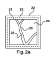
装置14は、インタフェースユニット22、処理ユニット20及びディスプレイ21を有する。血管画像24を受け取った後に、前記装置は、図2aに示されるようにディスプレイ21上に血管画像24を表示してもよい。ユーザは、インタフェースユニット22を使用して血管画像24とインタラクトしてもよい。前記ユーザは、血管画像24に関するユーザ入力を提供してもよく、前記ユーザ入力は、インタフェースユニット22により受け取られてもよい。前記ユーザ入力は、血管画像24内の識別子位置36及び血管画像24内の前記識別子により実行されるドラッグ方向42を有してもよい。
The
典型的な実施例において、インタフェースユニット22は、ディスプレイ21及びタッチコントローラ23を有するタッチスクリーンである。インタフェースユニット22が、タッチスクリーンである場合、血管画像24内の前記識別子は、前記タッチスクリーンに触れるユーザの指であってもよい。前記タッチスクリーンの表面は、この場合、モニタされ、タッチインタラクションは、タッチコントローラ23により受け取られ、処理されてもよい。しかしながら、これは、前記タッチスクリーンに触れるのに使用されうる前記ユーザの他の身体部分を除外しない。
In a typical embodiment, the
前記タッチスクリーンのタッチコントローラ23は、この場合、血管画像24上の識別子位置として前記ユーザの指のタッチ位置を検出してもよい。処理ユニット20は、前記タッチスクリーン上の前記検出された位置を血管画像24内の位置に位置合わせしてもよい。前記ユーザが、前記タッチスクリーン上で前記識別子のドラッグ移動を実行する場合、タッチコントローラ23は、ドラッグ方向42を検出する。
The
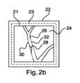
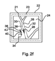
処理ユニット20は、図2bによると、血管画像24内の少なくとも1つの血管26の血管輪郭30を決定してもよい。更に、処理ユニット20は、血管画像24内の血管輪郭30の一部分だけの指示を提供してもよい。血管輪郭30の示された部分は、ディスプレイ21上の血管画像24において示されてもよい。更に、処理ユニット20は、血管画像24内の他の血管輪郭32を決定してもよい。他の血管輪郭32は、血管26において血管輪郭30の反対に配置されうる。
The
図2bにおいて、決定された血管輪郭30が、血管画像24内の血管26の現実の構造に従わず、血管26が狭窄28を有することが、更に示される。見られるように、決定された血管輪郭30は、狭窄28に従わない。この場合、処理ユニット20は、ユーザが血管輪郭30を補正することを可能にする。
In FIG. 2b it is further shown that the
図2cによると、ユーザは、指34でインタフェースユニット22のタッチスクリーンに触れ、ユーザ入力を提供してもよい。タッチ位置は、タッチコントローラ23を介して処理ユニット20により、すなわち、本実施例において前記タッチスクリーンにより決定されうる血管画像24内の識別子位置36を規定する。
According to FIG. 2c, the user may touch the touch screen of the
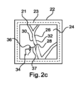
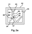
識別子位置36が、血管輪郭30から所定の距離範囲内でありうる距離37だけ離間される場合、前記処理ユニットは、図2dに示されるように、血管画像24内の血管輪郭30の少なくとも一部分38を示す。距離37が及びうる前記所定の距離範囲は、血管輪郭30から1mm乃至50mm、好ましくは2mm乃至40mm、より好ましくは3mm乃至30mm、最も好ましくは4mm乃至20mmに及びうる。好ましくは、距離37が、この所定の距離範囲内にある場合に限り、処理ユニット20は、血管画像24内の血管輪郭30の少なくとも一部分38を示す。
If the
前記ユーザが、インジケータ位置36から指を移動しない限り、血管輪郭30の示された部分38は、図2eに示されるように長さを増加する。前記ユーザが、識別子位置36から指をドラッグし始めるとすぐに、示された部分38の長さの増加が、行われる。これは、示された部分38の長さを増加する期間が、識別子位置36の検出で開始し、ドラッグ方向42の検出で終了することを意味する。前記増加の増加率は、前記ユーザが血管輪郭30上の示された部分38のサイズを正確に規定することができるように事前に規定され、選択されうる。
Unless the user moves his finger from the
ドラッグ方向42は、タッチコントローラ23により検出され、プロセッサユニット20により決定されてもよい。ドラッグ方向42を検出すると、処理ユニット20は、血管輪郭30の示された部分38と前記ドラッグ方向との間の角度を決定する。前記各土決定の結果が、第1の所定の角度範囲33内である場合、血管輪郭30の示された部分38は、プロセッサユニット20により血管輪郭30に沿って移動される。前記移動は、図2fに示されるように、ドラッグ方向42において、前記識別子、すなわち前記ユーザの指を追う。この典型的な実施例において、前記ユーザは、識別子位置36から血管画像24内の位置40まで指をドラッグしてもよい。図2e及び図2fの間で、示された部分38は、血管輪郭30に沿って狭窄28の始点から実質的に狭窄28の中心まで移動する。
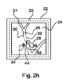
The
図2gは、位置40から位置44までの方向46へのドラッグ移動の変化を示し、方向46に沿った前記ドラッグ移動は、タッチコントローラ23により受け取られてもよい。方向46に沿って前記ドラッグ移動を決定すると、処理ユニット20は、方向46と示された部分38との間の角度が第2の所定の角度範囲内であるかどうかを決定する。前記決定された角度が、第2の所定の角度範囲35内である場合、血管輪郭30は、示された部分38の位置において及び/又はその周りでデフォルトである。前記変形は、示された部分38が、血管輪郭30の以前の伸長に垂直に移動する。残りの血管輪郭30に対する接続は、示された部分38の移動に適合される。
2g shows a change in drag movement in
図2gに見られるように、変形された血管輪郭30は、まだ、狭窄28とは異なる。前記ユーザは、位置44において開始する方向48への前記ドラッグ移動の更なる変更を実行してもよい。方向48に沿った前記ドラッグ移動と示された部分38との間の角度が第1の所定の角度範囲33の範囲内である場合、示された部分38は、方向48に基づいて血管輪郭30に沿って変形された血管輪郭30とともに移動する。血管輪郭30の変形された部分は、この場合、血管輪郭30に沿って移動されうる。これは、血管輪郭30が血管画像24内の血管26の構造を正確にカバーするように狭窄28の輪郭の正確なカバーの結果となりうる。
As seen in FIG. 2g, the modified
図3及び4によるインタフェースユニット22の更なる典型的な実施例において、インタフェースユニット22は、マウス、又は電子ペンを有してもよい。
In further exemplary embodiments of the
図3において、インタフェースユニット22は、マウスを有し、ディスプレイ21上に示される血管画像24上のポインタとのクリックインタラクションは、識別子位置36を規定する。ドラッグ方向42は、前記マウスをクリック中に前記ポインタをドラッグすることにより入力されてもよい。
In FIG. 3, the
図4において、インタフェースユニット22は、電子ペンを有する。ディスプレイ21上の前記電子ペンの接触位置は、血管画像24内の識別子位置36を規定してもよい。ドラッグ方向42は、血管画像24に沿って前記接触された電子ペンをドラッグすることにより入力されてもよい。
In FIG. 4, the
図5は、示された部分38とともに血管輪郭30を示す。示された部分48に平行である線31は、前記ドラッグ移動と示された部分38との間の角度の決定を説明するために描かれている。線31は、識別子位置36と交差する。ドラッグ方向42における前記ドラッグ移動も示される。更に示されるのは、第1の所定の角度範囲33である。ドラッグ方向42は、第1の所定の角度範囲33内である角度を持つ。これは、血管輪郭30の変形が実行されていない場合に血管輪郭30に沿った示された部分38の移動を生じてもよい。血管輪郭30の変形が、既に実行されている場合、変形された血管輪郭30全体は、血管輪郭30に沿って示された部分38とともに移動する。方向42が、図5の下を指しているが、方向42が、図5の上を指しうることは除外されない。示された部分38は、したがって、血管輪郭30に沿って両方の方向に移動してもよい。
FIG. 5 shows a
前記第1の所定の範囲は、+45°乃至-45°及び+135°乃至-135°、好ましくは+30°乃至-30°及び+150°乃至-150°、より好ましくは+15°乃至-15°及び+165°乃至-165°、最も好ましくは0°乃至180°に及んでもよく、0°及び180°は、前記輪郭に平行である。 The first predetermined range is +45° to -45° and +135° to -135°, preferably +30° to -30° and +150° to -150°, more preferably +15° to -15° and +165°. It may range from 0° to -165°, most preferably from 0° to 180°, with 0° and 180° being parallel to said contour.
図6は、第2の所定の角度範囲35を示す。方向46は、識別子位置36において開始してもよい血管輪郭30に向かうドラッグ方向42を示す。方向46と線31との間の角度が、第2の所定の角度範囲35内である場合、示された部分38は、血管輪郭30に垂直に移動し、これは、血管輪郭30の変形をもたらす。方向46が、図6において右を指しているが、方向46が左を指しうることは除外されない。これは、左への血管輪郭30の変形をもたらす。
FIG. 6 shows a second predetermined
前記第2の所定の角度範囲は、+45°乃至+135°及び-45°乃至-135°、好ましくは+30°乃至+120°及び-30°乃至-120°、より好ましくは+15°乃至+105°及び-15°乃至-105°、最も好ましくは+90°乃至-90°、すなわち前記輪郭に垂直に及んでもよい。 The second predetermined angular range is +45° to +135° and -45° to -135°, preferably +30° to +120° and -30° to -120°, more preferably +15° to +105° and - It may range from 15° to -105°, most preferably from +90° to -90°, ie perpendicular to said contour.
図7は、血管画像とインタラクトする方法100の方法ステップ101乃至110を示す図を示す。方法100は、図1による血管画像とインタラクトする装置14又は血管画像とインタラクトするシステム10を用いて実行されてもよい。以下において、図7の方法ステップは、図2a乃至2hを参照して説明される。一実施例において、前記方法は、コンピュータ実施方法である。
FIG. 7 shows a diagram illustrating method steps 101-110 of a
前記方法は、図2aに示されるように、装置14のディスプレイ21上に血管画像24を表示するステップ101を有する。
The method comprises a
決定するステップ102において、血管画像24内の少なくとも1つの血管26の血管輪郭30は、図2bに示されるように、決定される。前記決定は、処理ユニット20で実行されてもよい。更に、血管画像24内の更なる血管輪郭32が、決定されてもよい。更なる血管輪郭32は、血管26において血管輪郭30の反対側に配置されうる。
In the determining
血管26は、狭窄28を有しうる。図2bに見られるように、決定された血管輪郭30は、狭窄28に従わない。この場合、前記方法は、ユーザが血管輪郭30を補正することを可能にする。
更なる決定するステップ103において、血管画像24内の識別子位置36により規定されるユーザ入力のタッチ位置は、図2cに示されるように、タッチコントローラ23を介してプロセッサユニット20により決定されてもよい。
In a further determining
示すステップ104において、識別子位置36が、血管輪郭30から前記所定の距離範囲内の距離37だけ離間されている場合、血管画像24内の血管輪郭30の少なくとも一部分38は、図2dに示されるように、示されてもよい。
In
検出するステップ105において、ドラッグインタラクションが、タッチコントローラ23により検出されてもよく、更なる決定するステップ106において、前記検出されたドラッグインタラクションのドラッグ方向42が、プロセッサユニット20により決定されうる。一例において、前記ドラッグ方向と血管輪郭30の現在示されている部分38との間の角度が、確立される。
In a detecting step 105 a drag interaction may be detected by the
タッチインタラクションが、識別子位置36において生じるが、前記タッチコントローラが、いかなるドラッグインタラクションもまだ検出していない場合、例えば、プロセッサユニット20は、示された部分38の長さを増加してもよい。前記増加の増加率は、前記ユーザが血管輪郭30上の示された部分38のサイズを正確に規定することができるように事前に規定され、選択されてもよい。
If a touch interaction occurs at the
移動するステップ107において、前記角度決定の結果が、第1の所定の角度範囲33内である場合、血管輪郭30の示された部分38は、プロセッサユニット20により血管輪郭30に沿って移動される。前記移動は、図2fに示されるように、ドラッグ方向42において、前記識別子、すなわち前記ユーザの指を追う。この典型的な実施例において、前記ユーザは、血管画像24において識別子位置36から位置40まで指をドラッグしてもよい。
In a moving
オプションの更なる移動するステップ108において、前記決定された角度が、第2の所定の角度範囲3内の角度に変化する場合、血管輪郭30は、示された部分38が、図2gに示されるように、血管輪郭30の以前の伸長と垂直に移動する(108)ように、変形してもよい。残りの血管輪郭30に対する接続は、示された部分38の移動に適合される。
In an optional further moving
オプションとして、ユーザが、変形された血管輪郭30が狭窄28とはまだ異なることを見つける場合、更なる移動するステップ109において、前記ユーザは、位置44において開始する方向48への前記ドラッグ移動の更なる変更を実行し、変形された血管輪郭30の示された部分38に、図2hに示されるように、方向48に基づいて移動させてもよい。
Optionally, if the user finds that the modified
オプションとして前記移動するステップを繰り返すことにより、オプションの記憶するステップ110において、ユーザが、示された血管輪郭により狭窄28の輪郭を十分にカバーすることが達成されたことを確証する場合、前記示された血管輪郭の最終的な位置及び形状は、例えば、幾何学的又は機能的血管分析ツールにおける、後の使用に対して記憶されてもよい。
Optionally, by repeating said moving step, in an
本発明の他の典型的な実施例において、例えば図1を参照して記載される適切な装置上で、先行する実施例の1つによる方法の方法ステップを実行するように構成されることにより特徴づけられるコンピュータプログラム又はコンピュータプログラム要素16が、提供される。
In another exemplary embodiment of the invention, by being configured to carry out the method steps of the method according to one of the preceding embodiments, for example on a suitable apparatus as described with reference to FIG. A characterized computer program or
コンピュータプログラム要素16は、したがって、本発明の一実施例の一部であってもよいコンピュータユニットに記憶されてもよい。例えば、前記コンピュータプログラムは、図1を参照して記載される装置の処理ユニット20により実行されてもよい。
このコンピューティングユニットは、上記の方法のステップを実行する又は実行を誘導するように構成されてもよい。更に、上記の装置のコンポーネントを動作するように構成されてもよい。前記コンピューティングユニットは、ユーザの命令を実行する及び/又は自動的に動作するように構成されることができる。コンピュータプログラムは、データプロセッサのワーキングメモリにロードされてもよい。したがって、前記データプロセッサは、本発明の方法を実行するように備えらえてもよい。 This computing unit may be configured to perform or direct the performance of the steps of the method described above. Furthermore, it may be configured to operate the components of the apparatus described above. The computing unit may be configured to execute user instructions and/or operate automatically. The computer program may be loaded into the working memory of the data processor. Accordingly, said data processor may be arranged to carry out the method of the invention.
本発明のこの典型的な実施例は、最初から本発明を使用するコンピュータプログラムと、アップデートを用いて既存のプログラムを本発明を使用するプログラムにするコンピュータプログラムとの両方をカバーする。 This exemplary embodiment of the invention covers both computer programs that use the invention from the beginning and computer programs that use updates to make existing programs use the invention.
更に、前記コンピュータプログラム要素は、上記の方法の典型的な実施例の手順を満たす全ての必要なステップを提供することができてもよい。 Furthermore, said computer program element may be able to provide all necessary steps fulfilling the procedure of an exemplary embodiment of the method described above.
本発明の更なる典型的な実施例によると、図1に示されるように、CD-ROMのようなコンピュータ可読媒体18が、提示され、前記コンピュータ可読媒体は、記憶されたコンピュータプログラム要素を持ち、コンピュータプログラム要素16は、先行するセクションにより記載されている。コンピュータプログラムは、他のハードウェアと一緒に又はその一部として供給される光記憶媒体又は半導体媒体のような、適切な媒体に記憶及び/又は分配されてもよいが、インターネット又は他の有線若しくは無線電気通信システムを介するような、他の形で分配されてもよい。
According to a further exemplary embodiment of the invention, as shown in FIG. 1, a computer
しかしながら、前記コンピュータプログラムは、ワールドワイドウェブのようなネットワーク上に提示されてもよく、このようなネットワークからデータプロセッサのワーキングメモリにダウンロードされることができる。本発明の更なる典型的な実施例によると、コンピュータプログラム要素をダウンロード可能にする媒体が提供され、前記コンピュータプログラム要素は、本発明の以前に記載された実施例の1つによる方法を実行するように構成される。 However, the computer program may also be presented on a network, such as the World Wide Web, and can be downloaded from such a network to the working memory of the data processor. According to a further exemplary embodiment of the invention, a medium is provided which makes it possible to download a computer program element, said computer program element carrying out the method according to one of the previously described embodiments of the invention. It is configured as follows.
本発明の実施例が、異なる対象を参照して記載されることに注意すべきである。特に、一部の実施例は、方法型請求項を参照して記載されるのに対し、他の実施例は、装置型請求項を参照して記載される。しかしながら、当業者は、上記の及び以下の記載から、他の形で通知されない限り、1つのタイプの対象に属するフィーチャの任意の組み合わせに加えて、異なる対象に関するフィーチャ間の任意の組み合わせも、本出願で開示されていると見なされることを推測する。しかしながら、全てのフィーチャは、組み合わせられて、前記フィーチャの単純な合計より多くの相乗効果を提供することができる。 It should be noted that embodiments of the invention are described with reference to different objects. In particular, some embodiments are described with reference to method-type claims, whereas other embodiments are described with reference to apparatus-type claims. However, those skilled in the art will appreciate from the description above and below that, unless otherwise informed, in addition to any combination of features belonging to one type of object, any combination between features relating to different objects also applies to this invention. infer what is deemed to be disclosed in the application. However, all features can be combined to provide more synergy than the simple sum of the features.
本発明が、図面及び先行する記載において詳細に図示及び記載されているが、このような図示及び記載は、限定的ではなく、実例的又は典型的であると見なされるべきである。本発明は、開示された実施例に限定されない。開示された実施例に対する他の変形例は、図面、開示及び従属請求項の検討から請求された発明を実施する当業者により理解及び達成されることができる。 While the invention has been illustrated and described in detail in the drawings and foregoing description, such illustration and description are to be considered illustrative or exemplary rather than restrictive. The invention is not limited to the disclosed embodiments. Other variations to the disclosed embodiments can be understood and effected by those skilled in the art who practice the claimed invention from a study of the drawings, disclosure, and dependent claims.
請求項において、単語「有する」は、他の要素又はステップを除外せず、不定冠詞「a」又は「an」は、複数を除外しない。単一のプロセッサ又は他のユニットが、請求項に記載された複数のアイテムの機能を満たしてもよい。特定の方策が相互に異なる従属請求項に記載されているという単なる事実は、これらの方策の組み合わせが有利に使用されることができないことを示さない。請求項内のいかなる参照符号も、その範囲を限定するように解釈されるべきではない。 In the claims, the word "comprising" does not exclude other elements or steps, and the indefinite article "a" or "an" does not exclude a plurality. A single processor or other unit may fulfill the functions of several items recited in the claims. The mere fact that certain measures are recited in mutually different dependent claims does not indicate that a combination of these measures cannot be used to advantage. Any reference signs in the claims shall not be construed as limiting the scope.
Claims (15)
インタフェースユニットと、
処理ユニットと、
血管画像を表示するディスプレイと、
を有し、
前記インタフェースユニットが、前記血管画像に関するユーザ入力を受け取るように構成され、
前記処理ユニットが、
前記血管画像内の少なくとも1つの血管に対して、血管輪郭を決定し、
前記ユーザ入力から、前記血管画像内の識別子位置を決定し、ここで前記ユーザ入力が前記血管画像上の識別子で識別子位置を規定し、
前記決定された識別子位置が前記血管輪郭から所定の距離範囲内の距離だけ離間されている場合に、前記血管画像内の前記血管輪郭の少なくとも一部分を示し、
前記ユーザ入力から、ドラッグ方向を決定し、ここで前記ユーザ入力が前記識別子のドラッグ移動によって前記ドラッグ方向を規定し、
前記決定されたドラッグ方向に基づいて前記血管輪郭に沿って前記示された部分を移動する、
ように構成される、
装置。 A device for interacting with a blood vessel image, the device comprising:
an interface unit,
a processing unit;
a display that displays blood vessel images;
has
the interface unit is configured to receive user input regarding the blood vessel image;
The processing unit,
determining a blood vessel contour for at least one blood vessel in the blood vessel image;
from the user input, determining an identifier position within the blood vessel image, where the user input defines an identifier position with an identifier on the blood vessel image;
indicating at least a portion of the blood vessel contour in the blood vessel image when the determined identifier position is spaced from the blood vessel contour by a distance within a predetermined distance range;
determining a drag direction from the user input, where the user input defines the drag direction by drag movement of the identifier;
moving the indicated portion along the blood vessel contour based on the determined drag direction;
configured as,
Device.
前記決定されたドラッグ方向と前記示された部分との間の角度が第1の所定の角度範囲内である間に前記血管輪郭に沿って前記示された部分を移動する、
ように構成される、
請求項1に記載の装置。 The processing unit further includes:
moving the indicated portion along the blood vessel contour while an angle between the determined drag direction and the indicated portion is within a first predetermined angular range;
configured as,
The device according to claim 1.
前記長さを増加する期間が、前記識別子位置の検出で開始し、前記ドラッグ方向の検出で終了する、
請求項1乃至4のいずれか一項に記載の装置。 the processing unit is further configured to increase the length of the indicated portion of the vessel contour by a predetermined increment before determining the drag direction;
the period of increasing the length starts with the detection of the identifier position and ends with the detection of the drag direction;
Apparatus according to any one of claims 1 to 4.
画像取得装置と、
請求項1乃至10のいずれか一項に記載の血管画像とインタラクトする装置と、
を有し、
前記画像取得装置が、
血管画像を取得及び提供するように構成され、
前記血管画像とインタラクトする装置が、前記血管画像を受け取るように更に構成される、
システム。 A system for interacting with vascular images, the system comprising:
an image acquisition device;
A device for interacting with a blood vessel image according to any one of claims 1 to 10;
has
The image acquisition device includes:
configured to acquire and provide vascular images;
a device for interacting with the vascular image is further configured to receive the vascular image;
system.
前記画像取得装置は、血管造影装置である、
請求項11に記載のシステム。 The image acquisition device is configured to provide two-dimensional image data of a blood vessel image;
the image acquisition device is an angiography device;
The system according to claim 11.
前記ディスプレイが、血管画像を表示するステップと、
前記処理ユニットが、前記血管画像内の少なくとも1つの血管に対して、血管輪郭を決定するステップと、
前記処理ユニットが、前記インタフェースユニットにより受け取られたユーザ入力から、前記血管画像内の識別子位置を決定するステップであって、前記ユーザ入力が前記血管画像上の識別子で識別子位置を規定する、ステップと、
前記処理ユニットが、前記決定された識別子位置が前記血管輪郭から所定の距離範囲内の距離だけ離間されている場合に、前記血管画像内の前記血管輪郭の少なくとも一部分を示すステップと、
前記処理ユニットが、前記ユーザ入力から、ドラッグ方向を決定するステップであって、前記ユーザ入力が前記識別子のドラッグ移動によって前記ドラッグ方向を規定する、ステップと、
前記処理ユニットが、前記決定されたドラッグ方向に基づいて前記輪郭に沿って前記示された部分を移動するステップと、
を有する方法。 A method of operating a device for interacting with a blood vessel image , the device having an interface unit, a processing unit, and a display for displaying a blood vessel image, the method comprising:
the display displaying a blood vessel image;
the processing unit determining a blood vessel contour for at least one blood vessel in the blood vessel image;
the processing unit determining an identifier position within the blood vessel image from a user input received by the interface unit , the user input defining an identifier position with an identifier on the blood vessel image; ,
the processing unit indicating at least a portion of the blood vessel contour in the blood vessel image if the determined identifier position is spaced from the blood vessel contour by a distance within a predetermined distance range;
the processing unit determining a drag direction from the user input, the user input defining the drag direction by a drag movement of the identifier;
the processing unit moves the indicated portion along the contour based on the determined drag direction;
How to have.
Applications Claiming Priority (3)
| Application Number | Priority Date | Filing Date | Title |
|---|---|---|---|
| EP17306839.6 | 2017-12-20 | ||
| EP17306839.6A EP3503026A1 (en) | 2017-12-20 | 2017-12-20 | Device, system and method for interacting with vessel images |
| PCT/EP2018/084256 WO2019121128A1 (en) | 2017-12-20 | 2018-12-11 | Device, system and method for interacting with vessel images |
Publications (3)
| Publication Number | Publication Date |
|---|---|
| JP2021506473A JP2021506473A (en) | 2021-02-22 |
| JP2021506473A5 JP2021506473A5 (en) | 2022-01-06 |
| JP7356980B2 true JP7356980B2 (en) | 2023-10-05 |
Family
ID=60954829
Family Applications (1)
| Application Number | Title | Priority Date | Filing Date |
|---|---|---|---|
| JP2020534311A Active JP7356980B2 (en) | 2017-12-20 | 2018-12-11 | Devices, systems and methods for interacting with vascular images |
Country Status (5)
| Country | Link |
|---|---|
| US (1) | US11409422B2 (en) |
| EP (2) | EP3503026A1 (en) |
| JP (1) | JP7356980B2 (en) |
| CN (1) | CN111656402A (en) |
| WO (1) | WO2019121128A1 (en) |
Families Citing this family (2)
| Publication number | Priority date | Publication date | Assignee | Title |
|---|---|---|---|---|
| CN112116615B (en) * | 2019-11-19 | 2023-12-05 | 苏州润迈德医疗科技有限公司 | Method and device for acquiring blood vessel contour line according to blood vessel center line |
| JP2022080154A (en) * | 2020-11-17 | 2022-05-27 | 旭化成メディカル株式会社 | Image processing device and image processing program |
Citations (3)
| Publication number | Priority date | Publication date | Assignee | Title |
|---|---|---|---|---|
| JP2008543482A (en) | 2005-06-21 | 2008-12-04 | コーニンクレッカ フィリップス エレクトロニクス エヌ ヴィ | Method and apparatus for imaging blood vessels |
| JP2016503667A (en) | 2012-12-10 | 2016-02-08 | コーニンクレッカ フィリップス エヌ ヴェKoninklijke Philips N.V. | Digital ruler and reticle for renal denervation |
| WO2017117389A1 (en) | 2015-12-31 | 2017-07-06 | Acist Medical Systems, Inc. | Semi-automated image segmentation system and method |
Family Cites Families (20)
| Publication number | Priority date | Publication date | Assignee | Title |
|---|---|---|---|---|
| US5583977A (en) * | 1993-10-21 | 1996-12-10 | Taligent, Inc. | Object-oriented curve manipulation system |
| DE10312193A1 (en) * | 2003-03-19 | 2004-09-09 | Siemens Ag | Operation of a medical diagnostic imaging unit, especially a computer tomography or magnetic resonance imaging instrument, whereby image data and segment data sets are processed and presented simultaneously |
| KR101128572B1 (en) * | 2004-07-30 | 2012-04-23 | 애플 인크. | Gestures for touch sensitive input devices |
| CN101522105A (en) | 2006-10-16 | 2009-09-02 | 皇家飞利浦电子股份有限公司 | Method of performing tableside automatic vessel analysis in an operation room |
| BRPI0917609A2 (en) * | 2008-12-10 | 2019-10-15 | Koninklijke Philips Electrnics N. V. | '' system for performing vessel analysis, medical imaging workstation, method for performing vessel analysis, and, computer program product '' |
| WO2011018727A1 (en) * | 2009-08-12 | 2011-02-17 | Koninklijke Philips Electronics N.V. | Generating object data |
| US9782078B2 (en) * | 2011-08-14 | 2017-10-10 | Uzi Rahum | Device, system and method for blood vessel imaging and marking |
| KR102123061B1 (en) | 2012-11-27 | 2020-06-16 | 삼성전자주식회사 | Boundary segmentation apparatus and method based on user interaction |
| WO2014142468A1 (en) * | 2013-03-13 | 2014-09-18 | Samsung Electronics Co., Ltd. | Method of providing copy image and ultrasound apparatus therefor |
| US11096668B2 (en) * | 2013-03-13 | 2021-08-24 | Samsung Electronics Co., Ltd. | Method and ultrasound apparatus for displaying an object |
| WO2014207139A1 (en) * | 2013-06-28 | 2014-12-31 | Koninklijke Philips N.V. | Methods of utilizing image noise information |
| EP3054834B1 (en) * | 2013-10-07 | 2019-12-25 | Acist Medical Systems, Inc. | Systems and methods for controlled single touch zoom |
| US9406129B2 (en) | 2013-10-10 | 2016-08-02 | Medtronic, Inc. | Method and system for ranking instruments |
| EP3161786B1 (en) * | 2014-06-25 | 2019-10-30 | Koninklijke Philips N.V. | Imaging device for registration of different imaging modalities |
| CN104809730B (en) * | 2015-05-05 | 2017-10-03 | 上海联影医疗科技有限公司 | The method and apparatus that tracheae is extracted from chest CT image |
| KR101690655B1 (en) | 2015-01-29 | 2016-12-28 | 삼성전자주식회사 | Medical imaging processing apparatus and medical image processing method thereof |
| JP6873981B2 (en) * | 2015-10-07 | 2021-05-19 | コーニンクレッカ フィリップス エヌ ヴェKoninklijke Philips N.V. | Mobile FFR simulation |
| TWI594206B (en) * | 2016-01-08 | 2017-08-01 | Nat Yang-Ming Univ | Cardiac medical imaging single chamber mapping system and method |
| JP6809851B2 (en) * | 2016-09-12 | 2021-01-06 | キヤノンメディカルシステムズ株式会社 | Medical image diagnostic equipment and medical image processing equipment |
| WO2018133098A1 (en) * | 2017-01-23 | 2018-07-26 | 上海联影医疗科技有限公司 | Vascular wall stress-strain state acquisition method and system |
-
2017
- 2017-12-20 EP EP17306839.6A patent/EP3503026A1/en not_active Withdrawn
-
2018
- 2018-12-11 JP JP2020534311A patent/JP7356980B2/en active Active
- 2018-12-11 EP EP18812188.3A patent/EP3729372A1/en active Pending
- 2018-12-11 US US16/955,824 patent/US11409422B2/en active Active
- 2018-12-11 WO PCT/EP2018/084256 patent/WO2019121128A1/en unknown
- 2018-12-11 CN CN201880087133.3A patent/CN111656402A/en active Pending
Patent Citations (3)
| Publication number | Priority date | Publication date | Assignee | Title |
|---|---|---|---|---|
| JP2008543482A (en) | 2005-06-21 | 2008-12-04 | コーニンクレッカ フィリップス エレクトロニクス エヌ ヴィ | Method and apparatus for imaging blood vessels |
| JP2016503667A (en) | 2012-12-10 | 2016-02-08 | コーニンクレッカ フィリップス エヌ ヴェKoninklijke Philips N.V. | Digital ruler and reticle for renal denervation |
| WO2017117389A1 (en) | 2015-12-31 | 2017-07-06 | Acist Medical Systems, Inc. | Semi-automated image segmentation system and method |
Also Published As
| Publication number | Publication date |
|---|---|
| WO2019121128A1 (en) | 2019-06-27 |
| CN111656402A (en) | 2020-09-11 |
| EP3503026A1 (en) | 2019-06-26 |
| US20200341622A1 (en) | 2020-10-29 |
| JP2021506473A (en) | 2021-02-22 |
| US11409422B2 (en) | 2022-08-09 |
| EP3729372A1 (en) | 2020-10-28 |
Similar Documents
| Publication | Publication Date | Title |
|---|---|---|
| EP2465094B1 (en) | Generating object data | |
| EP3025304B1 (en) | Registration system for registering an imaging device with a tracking device | |
| US9678620B2 (en) | Workflow for ambiguity guided interactive segmentation of lung lobes | |
| US8131028B2 (en) | Method and apparatus providing flexible measurement functionality for medical images | |
| US9349220B2 (en) | Curve correction in volume data sets | |
| CN109559801B (en) | Intelligent editing of image processing results | |
| EP3170144B1 (en) | Device, system and method for segmenting an image of a subject | |
| EP2817695B1 (en) | System and method for processing a pointer movement | |
| JP7356980B2 (en) | Devices, systems and methods for interacting with vascular images | |
| US20140218397A1 (en) | Method and apparatus for providing virtual device planning | |
| WO2018065257A1 (en) | Context sensitive magnifying glass | |
| US11460990B2 (en) | Precise positioning of a marker on a display | |
| CN107106106B (en) | Adaptive segmentation for rotational C-arm computed tomography with reduced angular range | |
| EP3607527B1 (en) | Quantitative evaluation of time-varying data | |
| EP1692662A1 (en) | Method of determining a sructure of a moving object | |
| WO2004084735A1 (en) | Deriving parameter information from blood flow signal | |
| CN113648073A (en) | Adjustment of augmented reality and/or virtual reality | |
| JP2017035125A (en) | Image processing system, image processing method, and program |
Legal Events
| Date | Code | Title | Description |
|---|---|---|---|
| A521 | Request for written amendment filed |
Free format text: JAPANESE INTERMEDIATE CODE: A523 Effective date: 20211122 |
|
| A621 | Written request for application examination |
Free format text: JAPANESE INTERMEDIATE CODE: A621 Effective date: 20211122 |
|
| A131 | Notification of reasons for refusal |
Free format text: JAPANESE INTERMEDIATE CODE: A131 Effective date: 20221108 |
|
| A977 | Report on retrieval |
Free format text: JAPANESE INTERMEDIATE CODE: A971007 Effective date: 20221109 |
|
| A521 | Request for written amendment filed |
Free format text: JAPANESE INTERMEDIATE CODE: A523 Effective date: 20230131 |
|
| A131 | Notification of reasons for refusal |
Free format text: JAPANESE INTERMEDIATE CODE: A131 Effective date: 20230502 |
|
| A521 | Request for written amendment filed |
Free format text: JAPANESE INTERMEDIATE CODE: A523 Effective date: 20230731 |
|
| TRDD | Decision of grant or rejection written | ||
| A01 | Written decision to grant a patent or to grant a registration (utility model) |
Free format text: JAPANESE INTERMEDIATE CODE: A01 Effective date: 20230905 |
|
| A61 | First payment of annual fees (during grant procedure) |
Free format text: JAPANESE INTERMEDIATE CODE: A61 Effective date: 20230925 |
|
| R150 | Certificate of patent or registration of utility model |
Ref document number: 7356980 Country of ref document: JP Free format text: JAPANESE INTERMEDIATE CODE: R150 |