JP7355774B2 - Transmission device and transmission method - Google Patents
Transmission device and transmission method Download PDFInfo
- Publication number
- JP7355774B2 JP7355774B2 JP2021031497A JP2021031497A JP7355774B2 JP 7355774 B2 JP7355774 B2 JP 7355774B2 JP 2021031497 A JP2021031497 A JP 2021031497A JP 2021031497 A JP2021031497 A JP 2021031497A JP 7355774 B2 JP7355774 B2 JP 7355774B2
- Authority
- JP
- Japan
- Prior art keywords
- signal
- symbols
- time
- phase
- phase change
- Prior art date
- Legal status (The legal status is an assumption and is not a legal conclusion. Google has not performed a legal analysis and makes no representation as to the accuracy of the status listed.)
- Active
Links
Images


Classifications
-
- H—ELECTRICITY
- H04—ELECTRIC COMMUNICATION TECHNIQUE
- H04B—TRANSMISSION
- H04B7/00—Radio transmission systems, i.e. using radiation field
- H04B7/02—Diversity systems; Multi-antenna system, i.e. transmission or reception using multiple antennas
- H04B7/04—Diversity systems; Multi-antenna system, i.e. transmission or reception using multiple antennas using two or more spaced independent antennas
- H04B7/06—Diversity systems; Multi-antenna system, i.e. transmission or reception using multiple antennas using two or more spaced independent antennas at the transmitting station
- H04B7/0613—Diversity systems; Multi-antenna system, i.e. transmission or reception using multiple antennas using two or more spaced independent antennas at the transmitting station using simultaneous transmission
- H04B7/0667—Diversity systems; Multi-antenna system, i.e. transmission or reception using multiple antennas using two or more spaced independent antennas at the transmitting station using simultaneous transmission of delayed versions of same signal
- H04B7/0671—Diversity systems; Multi-antenna system, i.e. transmission or reception using multiple antennas using two or more spaced independent antennas at the transmitting station using simultaneous transmission of delayed versions of same signal using different delays between antennas
-
- H—ELECTRICITY
- H04—ELECTRIC COMMUNICATION TECHNIQUE
- H04B—TRANSMISSION
- H04B7/00—Radio transmission systems, i.e. using radiation field
- H04B7/02—Diversity systems; Multi-antenna system, i.e. transmission or reception using multiple antennas
- H04B7/04—Diversity systems; Multi-antenna system, i.e. transmission or reception using multiple antennas using two or more spaced independent antennas
- H04B7/0413—MIMO systems
- H04B7/0417—Feedback systems
- H04B7/0421—Feedback systems utilizing implicit feedback, e.g. steered pilot signals
-
- H—ELECTRICITY
- H04—ELECTRIC COMMUNICATION TECHNIQUE
- H04B—TRANSMISSION
- H04B7/00—Radio transmission systems, i.e. using radiation field
- H04B7/02—Diversity systems; Multi-antenna system, i.e. transmission or reception using multiple antennas
- H04B7/04—Diversity systems; Multi-antenna system, i.e. transmission or reception using multiple antennas using two or more spaced independent antennas
- H04B7/0413—MIMO systems
- H04B7/0456—Selection of precoding matrices or codebooks, e.g. using matrices antenna weighting
-
- H—ELECTRICITY
- H04—ELECTRIC COMMUNICATION TECHNIQUE
- H04B—TRANSMISSION
- H04B7/00—Radio transmission systems, i.e. using radiation field
- H04B7/02—Diversity systems; Multi-antenna system, i.e. transmission or reception using multiple antennas
- H04B7/04—Diversity systems; Multi-antenna system, i.e. transmission or reception using multiple antennas using two or more spaced independent antennas
- H04B7/06—Diversity systems; Multi-antenna system, i.e. transmission or reception using multiple antennas using two or more spaced independent antennas at the transmitting station
- H04B7/0613—Diversity systems; Multi-antenna system, i.e. transmission or reception using multiple antennas using two or more spaced independent antennas at the transmitting station using simultaneous transmission
- H04B7/0615—Diversity systems; Multi-antenna system, i.e. transmission or reception using multiple antennas using two or more spaced independent antennas at the transmitting station using simultaneous transmission of weighted versions of same signal
-
- H—ELECTRICITY
- H04—ELECTRIC COMMUNICATION TECHNIQUE
- H04J—MULTIPLEX COMMUNICATION
- H04J11/00—Orthogonal multiplex systems, e.g. using WALSH codes
-
- H—ELECTRICITY
- H04—ELECTRIC COMMUNICATION TECHNIQUE
- H04L—TRANSMISSION OF DIGITAL INFORMATION, e.g. TELEGRAPHIC COMMUNICATION
- H04L27/00—Modulated-carrier systems
- H04L27/26—Systems using multi-frequency codes
- H04L27/2601—Multicarrier modulation systems
- H04L27/2602—Signal structure
- H04L27/261—Details of reference signals
- H04L27/2613—Structure of the reference signals
- H04L27/26134—Pilot insertion in the transmitter chain, e.g. pilot overlapping with data, insertion in time or frequency domain
Landscapes
- Engineering & Computer Science (AREA)
- Computer Networks & Wireless Communication (AREA)
- Signal Processing (AREA)
- Radio Transmission System (AREA)
Description
本開示は、特にマルチアンテナを用いた通信を行う送信装置および受信装置に関する。 The present disclosure particularly relates to a transmitting device and a receiving device that perform communication using multiple antennas.
直接波が支配的なLOS(Line of Sight)環境において、マルチアンテナを用いた通信方法として例えばMIMO(Multiple-Input Multiple-Output)と呼ばれる通信方法で、良好な受信品質を得るための送信方法として、非特許文献1に記載されている方式がある。
In a LOS (Line of Sight) environment where direct waves are dominant, a communication method using multiple antennas, for example, a communication method called MIMO (Multiple-Input Multiple-Output), is used as a transmission method to obtain good reception quality. There is a method described in ,
本開示の非限定的な実施例は、LOSを含む伝播環境においてデータの受信品質を向上させる送信装置を提供する。 Non-limiting embodiments of the present disclosure provide a transmitting apparatus that improves the reception quality of data in a propagation environment that includes LOS.
本開示の一態様に係る送信装置は、Cyclic Shift Diversity法を行うことによって生成される第1の制御信号と第2の制御信号、及び、第1の信号処理及び第2の信号処理を行うことによって生成される位相変更後の第1の送信信号列z1(i)と位相変更後の第2の送信信号列z2(i)を生成し、前記iはシンボル番号である信号処理回路と、シングルキャリアモードにおいてマルチアンテナを介して前記第1の制御信号と前記位相変更後の第1の送信信号列z1(i)及び前記第2の制御信号と前記位相変更後の第2の送信信号列z2(i)を送信する送信器とを備え、前記第1の信号処理において、周期Nで周期的に変わる第1の位相変更値に従って、第1の変調信号列s1(i)の複数のデータシンボル及び第2の変調信号列s2(i)の複数のデータシンボルの位相変更を行い、前記Nは2以上の整数であり、第1の変調信号列s1(i)に適用される第1の位相変更値は、第2の変調信号列s2(i)に適用される第1の位相変更値と絶対値が等しく、正負の符号が異なり、前記第2の信号処理において、前記位相変更後の第1の変調信号列s1(i)と前記位相変更後の第2の変調信号列s2(i)から前記第1の送信信号列z1(i)と前記第2の送信信号列z2(i)を生成し、前記第1の送信信号列z1(i)と前記第2の送信信号列z2(i)のそれぞれに対して提供される時間的に一定の第2の位相変更値に従って、前記第1の送信信号列z1(i)と前記第2の送信信号列z2(i)に対して位相変更を行う。 A transmitting device according to an aspect of the present disclosure performs a first control signal and a second control signal generated by performing a cyclic shift diversity method, and a first signal processing and a second signal processing. A first transmission signal sequence z1(i) after the phase change and a second transmission signal sequence z2(i) after the phase change are generated by a signal processing circuit, where i is a symbol number, and a single signal processing circuit. In carrier mode, the first control signal and the phase-changed first transmission signal sequence z1(i) and the second control signal and the phase-changed second transmission signal sequence z2 are transmitted via a multi-antenna. (i), and in the first signal processing, a plurality of data symbols of the first modulated signal sequence s1(i) are transmitted according to a first phase change value that periodically changes with a period N. and changing the phase of a plurality of data symbols of the second modulated signal sequence s2(i), where N is an integer of 2 or more, and the first phase applied to the first modulated signal sequence s1(i). The change value has the same absolute value as the first phase change value applied to the second modulated signal sequence s2(i), has a different positive or negative sign, and in the second signal processing, the first phase change value applied to the second modulated signal sequence s2(i) The first transmission signal sequence z1(i) and the second transmission signal sequence z2(i) are obtained from the first modulated signal sequence s1(i) and the second modulated signal sequence s2(i) after the phase change. the first transmission signal sequence z1(i) and the second transmission signal sequence z2(i) according to temporally constant second phase change values provided to each of the first transmission signal sequence z1(i) and the second transmission signal sequence z2(i). The phase of the transmission signal sequence z1(i) and the second transmission signal sequence z2(i) is changed.
本開示の一態様に係る送信方法は、送信装置によって実行される送信方法であって、Cyclic Shift Diversity法を行うことによって生成される第1の制御信号と第2の制御信号、及び、第1の信号処理及び第2の信号処理を行うことによって生成される位相変更後の第1の送信信号列z1(i)と位相変更後の第2の送信信号列z2(i)を生成し、前記iはシンボル番号であるステップと、シングルキャリアモードにおいてマルチアンテナを介して前記第1の制御信号と前記位相変更後の第1の送信信号列z1(i)及び前記第2の制御信号と前記位相変更後の第2の送信信号列z2(i)を送信するステップとを含み、前記第1の信号処理において、周期Nで周期的に変わる第1の位相変更値に従って、第1の変調信号列s1(i)の複数のデータシンボル及び第2の変調信号列s2(i)の複数のデータシンボルの位相変更を行い、前記Nは2以上の整数であり、第1の変調信号列s1(i)に適用される第1の位相変更値は、第2の変調信号列s2(i)に適用される第1の位相変更値と絶対値が等しく、正負の符号が異なり、前記第2の信号処理において、前記位相変更後の第1の変調信号列s1(i)と前記位相変更後の第2の変調信号列s2(i)から前記第1の送信信号列z1(i)と前記第2の送信信号列z2(i)を生成し、前記第1の送信信号列z1(i)と前記第2の送信信号列z2(i)のそれぞれに対して提供される時間的に一定の第2の位相変更値に従って、前記第1の送信信号列z1(i)と前記第2の送信信号列z2(i)に対して位相変更を行う。 A transmission method according to an aspect of the present disclosure is a transmission method performed by a transmitting device, and includes a first control signal, a second control signal, and a first control signal generated by performing a cyclic shift diversity method. A first transmission signal sequence z1(i) after the phase change and a second transmission signal sequence z2(i) after the phase change are generated by performing the signal processing and the second signal processing, and i is a symbol number, and the first control signal and the phase-changed first transmission signal sequence z1(i) and the second control signal and the phase are transmitted through multi-antennas in single carrier mode. transmitting the modified second transmission signal sequence z2(i), and in the first signal processing, the first modulated signal sequence is transmitted according to the first phase change value that periodically changes with a period N. The phases of a plurality of data symbols of s1(i) and a plurality of data symbols of a second modulated signal sequence s2(i) are changed, N is an integer of 2 or more, and the first modulated signal sequence s1(i ) is the same in absolute value as the first phase change value applied to the second modulated signal sequence s2(i), has a different positive or negative sign, and has a first phase change value applied to the second modulated signal sequence s2(i). In the process, the first transmission signal sequence z1(i) and the second a temporally constant second transmission signal sequence provided for each of the first transmission signal sequence z1(i) and the second transmission signal sequence z2(i). The phase of the first transmission signal sequence z1(i) and the second transmission signal sequence z2(i) is changed according to the phase change value of .
これらの概括的かつ特定の態様は、システム、装置及び方法の任意の組み合わせにより実現してもよい。 These general and specific aspects may be implemented by any combination of systems, apparatus, and methods.
このように本開示によれば、LOSを含む伝播環境においてデータの受信品質を向上させることができるため、品質の高い通信サービスを提供することができる。 As described above, according to the present disclosure, it is possible to improve the reception quality of data in a propagation environment including LOS, and thus it is possible to provide high-quality communication services.
本開示の一態様における更なる利点および効果は、明細書および図面から明らかにされる。かかる利点および/または効果は、いくつかの実施形態並びに明細書および図面に記載された特徴によってそれぞれ提供されるが、1つまたはそれ以上の同一の特徴を得るために必ずしも全てが提供される必要はない。 Further advantages and advantages of one aspect of the disclosure will become apparent from the specification and drawings. Such advantages and/or effects may be provided by each of the several embodiments and features described in the specification and drawings, but not necessarily all are provided in order to obtain one or more of the same features. There isn't.
(LOS環境における通信方法)
直接波が支配的なLOS環境において、マルチアンテナを用いた通信方法として例えばMIMOと呼ばれる通信方法で、良好な受信品質を得るための送信方法として、非特許文献1に記載されている方式がある。
(Communication method in LOS environment)
In a LOS environment where direct waves are dominant, a communication method using multiple antennas is, for example, a communication method called MIMO, and as a transmission method to obtain good reception quality, there is a method described in
図17は、非特許文献1に記載されている、送信アンテナ数2、送信変調信号(送信ストリーム)数2のときの、DVB-NGH(Digital Video Broadcasting -Next Generation Handheld)規格に基づいた送信装置の構成の一例を示している。送信装置では、符号化部002により符号化されたデータ003が、分配部004により、データ005A、データ005Bに分けられる。データ005Aは、インタリーバ004Aにより、インタリーブの処理、マッピング部006Aにより、マッピングの処理が施される。同様に、データ005Bは、インタリーバ004Bにより、インタリーブの処理、マッピング部006Bにより、マッピングの処理が施される。重み付け合成部008A、008Bは、マッピング後の信号007A、007Bを入力とし、それぞれ重み付け合成を行い、重み付け合成後の信号009A、016Bが生成される。重み付け合成後の信号016Bは、その後、位相変更が行われる。そして、無線部010A、010Bにより、例えば、OFDM(orthogonal frequency division multiplexing)に関連する処理、周波数変換、増幅などの処理が行われ、アンテナ012Aから送信信号011A、アンテナ012Bから送信信号011Bが送信される。
FIG. 17 shows a transmitting device based on the DVB-NGH (Digital Video Broadcasting - Next Generation Handheld) standard when the number of transmitting antennas is 2 and the number of transmitting modulated signals (transmitting streams) is 2, which is described in
従来の構成の場合、シングルストリームの信号をあわせて送信することを考慮しておらず、このような場合、特に、シングルストリームの受信装置におけるデータの受信品質を向上させるための新しい送信方法を導入するとよいと考えられる。 Conventional configurations do not consider transmitting single-stream signals together, and in such cases, a new transmission method is introduced to improve the data reception quality, especially in single-stream receivers. It is considered a good idea to do so.
以下、本開示の実施の形態について図面を参照して詳細に説明する。 Embodiments of the present disclosure will be described in detail below with reference to the drawings.
(実施の形態1)
本実施の形態の送信方法、送信装置、受信方法、受信装置について詳しく説明する。
(Embodiment 1)
The transmitting method, transmitting device, receiving method, and receiving device of this embodiment will be explained in detail.
図1に、本実施の形態における例えば、基地局、アクセスポイント、放送局等の送信装置の構成の一例を示す。誤り訂正符号化102は、データ101および制御信号100を入力とし、制御信号100に含まれる誤り訂正符号に関する情報(例えば、誤り訂正符号の情報、符号長(ブロック長)、符号化率)に基づき、誤り訂正符号化を行い、符号化データ103を出力する。なお、誤り訂正符号化部102は、インタリーバを具備していてもよく、インタリーバを具備していた場合、符号化後にデータの並び替えを行い、符号化データ103を出力してもよい。
FIG. 1 shows an example of the configuration of a transmitting device such as a base station, an access point, a broadcasting station, etc. in this embodiment.
マッピング部104は、符号化データ103、制御信号100を入力とし、制御信号100に含まれる変調信号の情報に基づき、変調方式に対応するマッピングを行い、マッピング後の信号であるベースバンド信号105_1、および、マッピング後の信号であるベースバンド信号105_2を出力する。なお、マッピング部104は、第1の系列を用いて、マッピング後の信号105_1を生成し、第2の系列を用いて、マッピング後の信号105_2を生成する。このとき、第1の系列と第2の系列は異なる。
The
信号処理部106は、マッピング後の信号105_1、105_2、信号群110、制御信号100を入力とし、制御信号100に基づいて、信号処理を行い、信号処理後の信号106_A、106_Bを出力する。このとき、信号処理後の信号106_Aをu1(i)、信号処理後の信号106_Bをu2(i)とあらわす。iはシンボル番号であり、例えば、iは0以上の整数とする。なお、信号処理については、図2を用いて、後で説明する。
The
無線部107_Aは、信号処理後の信号106_A、制御信号100を入力とし、制御信号100に基づき、信号処理後の信号106_Aに対し、処理を施し、送信信号108_Aを出力する。そして、送信信号108_Aは、アンテナ部#A 109_Aから電波として出力される。
The radio unit 107_A receives the signal 106_A after signal processing and the
同様に、無線部107_Bは、信号処理後の信号106_B、制御信号100を入力とし、制御信号100に基づき、信号処理後の信号106_Bに対し、処理を施し、送信信号108_Bを出力する。そして、送信信号108_Bは、アンテナ部#B 109_Bから電波として出力される。
Similarly, the radio unit 107_B receives the signal 106_B after signal processing and the
アンテナ部#A 109_Aは、制御信号100を入力としている。このとき、制御信号100に基づいて、送信信号108_Aに対し処理を施し、電波として出力する。ただし、アンテナ部#A 109_Aは、制御信号100を入力としなくてもよい。
The antenna section #A 109_A receives the
同様に、アンテナ部#B 109_Bは、制御信号100を入力としている。このとき、制御信号100に基づいて、送信信号108_Bに対し処理を施し、電波を出力する。ただし、アンテナ部#B 109_Bは、制御信号100を入力としなくてもよい。
Similarly, the antenna section #B 109_B receives the
なお、制御信号100は、図1の通信相手である装置が送信した情報に基づいて生成されてもよいし、図1の装置は入力部を具備し、その入力部から入力された情報に基づいて生成されてもよい。
Note that the
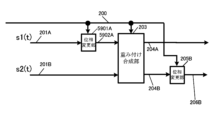
図2は、図1における信号処理部106の構成の一例を示している。重み付け合成部(プリコーディング部)203はマッピング後の信号201A(図1のマッピング後の信号105_1)、および、マッピング後の信号201B(図1のマッピング後の信号105_2)、および、制御信号200(図1の制御信号100)を入力とし、制御信号200に基づいて重み付け合成(プリコーディング)を行い、重み付け後の信号204Aおよび重み付け後の信号204Bを出力する。このとき、マッピング後の信号201Aをs1(t)、マッピング後の信号201Bをs2(t)、重み付け後の信号204Aをz1(t)、重み付け後の信号204Bをz2’(t)とあらわす。なお、tは一例として、時間とする。s1(t)、s2(t)、z1(t)、z2’(t)は複素数で定義される。したがって、実数であってもよい。
FIG. 2 shows an example of the configuration of the
重み付け合成部(プリコーディング部)203は、以下の演算を行う。 The weighted synthesis unit (precoding unit) 203 performs the following calculations.

式(1)において、a、b、c、dは複素数で定義する。なお、a、b、c、dは実数であってもよい。なお、iはシンボル番号とする。 In formula (1), a, b, c, and d are defined as complex numbers. Note that a, b, c, and d may be real numbers. Note that i is a symbol number.
そして、位相変更部205Bは、重み付け合成後の信号204B、および、制御信号200を入力とし、制御信号200に基づき、重み付け合成後の信号204Bに対し、位相変更を施し、位相変更後の信号206Bを出力する。なお、位相変更後の信号206Bをz2(t)であらわし、z2(t)は複素数で定義する。なお、z2(t)は実数であってもよい。
Then, the
位相変更部205Bの具体的動作について説明する。位相変更部205Bでは、例えば、z2’(i)に対しy(i)の位相変更を施す。したがって、z2(i)=y(i)×z2’(i)とあらわすことができる。iはシンボル番号であり、iは0以上の整数とする。
The specific operation of the
例えば、位相変更の値を以下のように設定する。Nは2以上の整数であり、Nは位相変更の周期となる。Nは3以上の奇数に設定するとデータの受信品質が向上する可能性がある。 For example, set the phase change value as follows. N is an integer of 2 or more, and N is the period of phase change. If N is set to an odd number of 3 or more, the data reception quality may improve.

jは虚数単位である。ただし、式(2)は、あくまでも例であり、これに限ったものではない。そこで、位相変更値y(i)=ej×δ(i)であらわす。 j is an imaginary unit. However, formula (2) is just an example, and is not limited to this. Therefore, the phase change value is expressed as y(i)=e j×δ(i) .
このときz1(i)およびz2(i)は次式であらわすことができる。 At this time, z1(i) and z2(i) can be expressed by the following formula.

なお、δ(i)は実数である。そして、z1(i)とz2(i)は、同一時間、同一周波数(同一周波数帯)で、送信装置から送信される。 Note that δ(i) is a real number. Then, z1(i) and z2(i) are transmitted from the transmitting device at the same time and at the same frequency (same frequency band).
式(3)において、位相変更の値は、式(2)に限ったものではなく、例えば、周期的、規則的に位相を変更するような方法が考えられる。 In Equation (3), the value of the phase change is not limited to Equation (2), and for example, a method of periodically and regularly changing the phase can be considered.
式(1)および式(3)における行列(プリコーディング行列)を The matrix (precoding matrix) in equation (1) and equation (3) is

とする。例えば、行列Fは、以下のいずれかの行列を用いることが考えられる。 shall be. For example, as the matrix F, one of the following matrices may be used.


なお、式(5)、式(6)、式(7)、式(8)、式(9)、式(10)、式(11)、式(12)において、αは実数であってもよいし、虚数であってもよく、βは実数であってもよいし、虚数であってもよい。ただし、αは0(ゼロ)ではない。そして、βも0(ゼロ)ではない。 Note that in equation (5), equation (6), equation (7), equation (8), equation (9), equation (10), equation (11), and equation (12), even if α is a real number, β may be a real number or an imaginary number. However, α is not 0 (zero). And β is also not 0 (zero).


なお、式(13)、式(15)、式(17)、式(19)において、βは実数であってもよいし、虚数であってもよい。ただし、βは0(ゼロ)ではない。(θは実数) Note that in equation (13), equation (15), equation (17), and equation (19), β may be a real number or an imaginary number. However, β is not 0 (zero). (θ is a real number)


ただし、θ 11(i)、θ 21(i)、λ(i)はシンボル番号iの関数であり、実数である。λは例えば固定の値であり、実数であり、固定値でなくてもよい。αは実数であってもよいし、虚数であってもよい。βは実数であってもよいし、虚数であってもよい。ただし、αは0(ゼロ)ではない。そして、βも0(ゼロ)ではない。また、θ11、θ 21は実数である。 However, θ 11 (i), θ 21 (i), and λ(i) are functions of the symbol number i and are real numbers. For example, λ is a fixed value, a real number, and may not be a fixed value. α may be a real number or an imaginary number. β may be a real number or an imaginary number. However, α is not 0 (zero). And β is also not 0 (zero). Moreover, θ 11 and θ 21 are real numbers.
また、これら以外であって、下記に示すプリコーディング行列のいずれかを用いても、本開示の各実施の形態を実施することが可能である。 Moreover, each embodiment of the present disclosure can be implemented using any of the precoding matrices shown below other than these.


なお、式(34)、式(36)のβは実数であってもよいし、虚数であってもよい。ただし、βも0(ゼロ)ではない。 Note that β in equations (34) and (36) may be a real number or an imaginary number. However, β is also not 0 (zero).
挿入部207Aは、重み付け合成後の信号204A、時間tにおけるパイロットシンボル信号pa(t)251A、プリアンブル信号252、制御情報シンボル信号253、制御信号200を入力とし、制御信号200に含まれるフレーム構成の情報に基づき、フレーム構成に基づいたベースバンド信号208Aを出力する。
The
同様に、挿入部207Bは、位相変更後の信号206B、時間tにおけるパイロットシンボル信号pb(t)251B、プリアンブル信号252、制御情報シンボル信号253、制御信号200を入力とし、制御信号200に含まれるフレーム構成の情報に基づき、フレーム構成に基づいたベースバンド信号208Bを出力する。
Similarly, the
位相変更部209Bは、ベースバンド信号208B、および、制御信号200を入力とし、ベースバンド信号208Bに対し、制御信号200に基づいて、位相変更を行い、位相変更後の信号210Bを出力する。ベースバンド信号208Bをシンボル番号iの関数とし、x’(i)とあらわす。すると、位相変更後の信号x(i)210Bは、x(i)=ej×ε(i)×x’(i)とあらわすことができる。ここで、iは0以上の整数であり、jは虚数単位である。
The
なお、後で説明するが、位相変更部209Bの動作としては、非特許文献2、非特許文献3で記載されているCDD(Cyclic Delay Diversity)又はCSD(Cyclic Shift Diversity)であってもよい。以後、CDD/CSDと記載する。そして、位相変更部209Bは、周波数軸方向に存在するシンボルに対し、位相変更を行う。つまり、位相変更部209Bは、データシンボル、パイロットシンボル、制御情報シンボルなどに対し位相変更を施す。
As will be explained later, the operation of the
図3は、図1の無線部107_A、107_Bの構成の一例である。シリアルパラレル変換部302は、信号301、および、制御信号300(図1の制御信号100)を入力とし、制御信号300に基づき、シリアルパラレル変換を行い、シリアルパラレル変換後の信号303を出力する。
FIG. 3 shows an example of the configuration of the wireless sections 107_A and 107_B in FIG. 1. The serial-to-
逆フーリエ変換部304は、シリアルパラレル変換後の信号303、および、制御信号300を入力とし、制御信号300に基づいて、逆フーリエ変換として、例えば、逆高速フーリエ変換(IFFT:Inverse Fast Fourier Transform)を施し、逆フーリエ変換後の信号305を出力する。
The inverse
処理部306は、逆フーリエ変換後の信号305、制御信号300を入力とし、制御信号300に基づき、周波数変換、増幅等の処理を施し、変調信号307を出力する。
The
例えば、信号301を図1の信号処理後の信号106_Aとした場合、変調信号307は図1の送信信号108_Aに相当する。また、信号301を図1の信号処理後の信号106_Bとした場合、変調信号307は図1の送信信号108_Bに相当する。
For example, if the
図4は、図1の送信信号108_Aのフレーム構成である。図4において、横軸周波数(キャリア)、縦軸時間である。OFDMなどのマルチキャリア伝送方式を用いているため、キャリア方向にシンボルが存在している。そして、図4では、全てのキャリアのシンボルを示している。また、図4では、時刻$1から時刻$11のシンボルを示している。 FIG. 4 shows the frame structure of the transmission signal 108_A in FIG. 1. In FIG. 4, the horizontal axis represents frequency (carrier) and the vertical axis represents time. Since a multicarrier transmission method such as OFDM is used, symbols exist in the carrier direction. In FIG. 4, symbols of all carriers are shown. Further, in FIG. 4, symbols from time $1 to time $11 are shown.
図4では、パイロットシンボル401(図2のパイロット信号251A)、データシンボル402、その他のシンボル403を示している。このとき、パイロットシンボルは、例えば、PSK(Phase Shift Keying)のシンボルであり、このフレームを受信する受信装置がチャネル推定(伝搬路変動の推定)、周波数オフセット及び位相変動の推定を行うためのシンボルであり、例えば、図1の送信装置と、図4のフレームを受信する受信装置がパイロットシンボルの送信方法を共有しているとよい。
4 shows a pilot symbol 401 (
ところで、マッピング後の信号201A(図1のマッピング後の信号105_1)を「ストリーム#1」と名付け、マッピング後の信号201B(図1のマッピング後の信号105_2)を「ストリーム#2」と名付ける。なお、この点は、以降の説明でも同様である。
By the way, the mapped
データシンボル402は、図2による信号処理で生成したベースバンド信号208Aに相当するシンボルであり、したがって、データシンボル402は、「「ストリーム#1」のシンボルと「ストリーム#2」のシンボルの両者を含んだシンボル」、または、「「ストリーム#1」のシンボル」、または、「「ストリーム#2」のシンボル」のいずれかであり、これは、重み付け合成部203で使用するプリコーディング行列の構成によって決まる。
The data symbol 402 is a symbol corresponding to the
その他のシンボル403は、図2におけるプリアンブル信号242、および、制御情報シンボル信号253に相当するシンボルである。ただし、その他のシンボルが、プリアンブル、制御情報シンボル以外のシンボルを含んでいてもよい。このとき、プリアンブルは、(制御用の)データを伝送してもよいし、信号検出のためシンボル、周波数同期及び時間同期を行うためのシンボル、チャネル推定のためのシンボル(伝搬路変動の推定を行うためのシンボル)などで構成されている。そして、制御情報シンボルは、図4のフレームを受信した受信装置が、データシンボルの復調及び復号を実現するための制御情報を含んだシンボルとなる。
Other symbols 403 are symbols corresponding to the preamble signal 242 and the control
例えば、図4における時刻$1から時刻4の全てのキャリアは、その他のシンボル403となる。そして、
・時刻$5において、
キャリア1からキャリア11はデータシンボル402となる。以降、
キャリア12はパイロットシンボル401となり、
キャリア13からキャリア23はデータシンボル402となり、
キャリア24はパイロットシンボル401となり、以後の記載は省略する、
・時刻$6において、
キャリア1及びキャリア2はデータシンボル402となり、
キャリア3はパイロットシンボル401となり、以後の記載は省略する、
・時刻$7から時刻$10までの記載は省略する、
・時刻$11において、
キャリア1からキャリア29までは、記載を省略し、
時刻$11のキャリア30はパイロットシンボル401となり、
時刻$11のキャリア31からキャリア36はデータシンボル402となる。
For example, all carriers from time $1 to
・At time $5,
Carrier 13 to carrier 23 becomes data symbol 402,
The
・At time $6,
- Omit the description from time $7 to time $10.
・At time $11,
The description is omitted for
図5は、図1の送信信号108_Bのフレーム構成である。図5において、横軸周波数(キャリア)、縦軸時間である。OFDMなどのマルチキャリア伝送方式を用いているため、キャリア方向にシンボルが存在している。そして、図5では、全てのキャリアのシンボルを示している。また、図5では、時刻$1から時刻$11のシンボルを示している。 FIG. 5 shows the frame structure of the transmission signal 108_B in FIG. 1. In FIG. 5, the horizontal axis represents frequency (carrier) and the vertical axis represents time. Since a multicarrier transmission method such as OFDM is used, symbols exist in the carrier direction. In FIG. 5, symbols of all carriers are shown. Further, in FIG. 5, symbols from time $1 to time $11 are shown.
図5では、パイロットシンボル501(図2のパイロット信号251B)、データシンボル502、その他のシンボル503を示している。このとき、パイロットシンボルは、例えば、PSKのシンボルであり、このフレームを受信する受信装置がチャネル推定(伝搬路変動の推定)、周波数オフセット及び位相変動の推定を行うためのシンボルであり、例えば、図1の送信装置と、図5のフレームを受信する受信装置がパイロットシンボルの送信方法を共有しているとよい。
FIG. 5 shows a pilot symbol 501 (
データシンボル502は、図2による信号処理で生成したベースバンド信号208Bに相当するシンボルであり、したがって、データシンボル502は、「「ストリーム#1」のシンボルと「ストリーム#2」のシンボルの両者を含んだシンボル」、または、「「ストリーム#1」のシンボル」、または、「「ストリーム#2」のシンボル」のいずれかであり、これは、重み付け合成部203で使用するプリコーディング行列の構成によって決まる。
The data symbol 502 is a symbol corresponding to the
その他のシンボル503は、図2におけるプリアンブル信号252、および、制御情報シンボル信号253に相当するシンボルである。ただし、その他のシンボルが、プリアンブル、制御情報シンボル以外のシンボルを含んでいてもよい。このとき、プリアンブルはデータ(例えば、制御用のデータ)を伝送してもよいし、信号検出のためのシンボル、周波数同期及び時間同期を行うためのシンボル、チャネル推定のためのシンボルなどで構成されている。そして、制御情報シンボルは、図5のフレームを受信した受信装置がデータシンボルの復調及び復号を実現するための制御情報を含んだシンボルとなる。
Other symbols 503 are symbols corresponding to the
例えば、図5における
・時刻$1から時刻$4において、
全てのキャリアは、その他のシンボル403となる。
・時刻$5において、
キャリア1からキャリア11はデータシンボル402となり、
キャリア12はパイロットシンボル401となり、
キャリア13からキャリア23はデータシンボル402となり、
キャリア24はパイロットシンボル401となり、以後、時刻$5におけるキャリアの記載は省略する。
・時刻$6において、
キャリア1及びキャリア2はデータシンボル402となり、
キャリア3はパイロットシンボル401となり、以後、時刻$6におけるキャリアの記載は省略する。
・時刻$7から時刻$10までの記載は省略する。
・時刻$11において、
キャリア1からキャリア29までの記載は省略し、
キャリア30はパイロットシンボル401となり、
キャリア31からキャリア36はデータシンボル402となる。
For example, from time $1 to time $4 in FIG.
All carriers become other symbols 403.
・At time $5,
Carrier 13 to carrier 23 becomes data symbol 402,
・At time $6,
- The description from time $7 to time $10 is omitted.
・At time $11,
The description of
図4のキャリアA、時刻$Bにシンボルが存在し、図5のキャリアA、時刻$Bにシンボルが存在したとき、図4のキャリアA、時刻$Bのシンボルと図5のキャリアA、時刻$Bのシンボルは、同一時間、同一周波数に送信される。なお、フレーム構成については、図4、図5に限ったものではなく、あくまでも、図4、図5はフレーム構成の例である。 When a symbol exists at carrier A, time $B in FIG. 4, and a symbol exists at carrier A, time $B in FIG. 5, the symbol at carrier A, time $B in FIG. The $B symbols are transmitted at the same time and on the same frequency. Note that the frame configuration is not limited to those shown in FIGS. 4 and 5, and FIGS. 4 and 5 are merely examples of frame configurations.
そして、図4、図5におけるその他のシンボルは、「図2におけるプリアンブル信号252、制御情報シンボル信号253」に相当するシンボルであり、したがって、図4のその他のシンボル403と同一時刻、かつ、同一周波数(同一キャリア)の図5のその他のシンボル503は、制御情報を伝送している場合、同一のデータ(同一の制御情報)を伝送している。
The other symbols in FIGS. 4 and 5 are symbols corresponding to "the
なお、図4のフレームと図5のフレームを受信装置は同時に受信することを想定しているが、図4のフレーム、または、図5のフレームを受信しても受信装置は送信装置が送信したデータを得ることは可能である。 It is assumed that the receiving device receives the frame in FIG. 4 and the frame in FIG. 5 at the same time, but even if the receiving device receives the frame in FIG. 4 or the frame in FIG. It is possible to obtain data.
図6は、図2の制御情報シンボル信号253を生成するための制御情報生成に関する部分の構成の一例を示している。 FIG. 6 shows an example of the configuration of a portion related to control information generation for generating the control information symbol signal 253 of FIG. 2. In FIG.
制御情報用マッピング部602は、制御情報に関するデータ601、制御信号600を入力とし、制御信号600に基づいた変調方式で、制御情報に関するデータ601に対し、マッピングを施し、制御情報用マッピング後の信号603を出力する。なお、制御情報用マッピング後の信号603は、図2の制御情報シンボル信号253に相当する。
The control
図7は、図1のアンテナ部#A 109_A、アンテナ部#B 109_Bの構成の一例を示している。アンテナ部#A 109_A、アンテナ部#B 109_Bが複数のアンテナで構成されている例である。 FIG. 7 shows an example of the configuration of antenna section #A 109_A and antenna section #B 109_B in FIG. 1. This is an example in which antenna section #A 109_A and antenna section #B 109_B are composed of a plurality of antennas.
分配部702は、送信信号701を入力とし、分配を行い、送信信号703_1、703_2、703_3、703_4を出力する。
The
乗算部704_1は、送信信号703_1、および、制御信号700を入力とし、制御信号700に含まれる乗算係数の情報に基づき、送信信号703_1に乗算係数を乗算し、乗算後の信号705_1を出力し、乗算後の信号705_1は、電波としてアンテナ706_1から出力される。
The multiplication unit 704_1 receives the transmission signal 703_1 and the
送信信号703_1をTx1(t)、乗算係数をW1とすると、乗算後の信号705_1は、Tx1(t)×W1とあらわされる。tは時間を示し、W1は複素数で定義することができ、したがって、実数であってもよい。 Assuming that the transmission signal 703_1 is Tx1(t) and the multiplication coefficient is W1, the signal 705_1 after multiplication is expressed as Tx1(t)×W1. t indicates time, and W1 can be defined as a complex number and therefore may be a real number.
乗算部704_2は、送信信号703_2、および、制御信号700を入力とし、制御信号700に含まれる乗算係数の情報に基づき、送信信号703_2に乗算係数を乗算し、乗算後の信号705_2を出力し、乗算後の信号705_2は、電波としてアンテナ706_2から出力される。
The multiplication unit 704_2 receives the transmission signal 703_2 and the
送信信号703_2をTx2(t)、乗算係数をW2とすると、乗算後の信号705_2は、Tx2(t)×W2とあらわされる。tは時間を示し、W2は複素数で定義することができ、したがって、実数であってもよい。 Assuming that the transmission signal 703_2 is Tx2(t) and the multiplication coefficient is W2, the signal 705_2 after multiplication is expressed as Tx2(t)×W2. t indicates time and W2 can be defined as a complex number and therefore may be a real number.
乗算部704_3は、送信信号703_3、および、制御信号700を入力とし、制御信号700に含まれる乗算係数の情報に基づき、送信信号703_3に乗算係数を乗算し、乗算後の信号705_3を出力し、乗算後の信号705_3は、電波としてアンテナ706_3から出力される。
The multiplication unit 704_3 receives the transmission signal 703_3 and the
送信信号703_3をTx3(t)、乗算係数をW3とすると、乗算後の信号705_3はTx3(t)×W3とあらわされる。W3は複素数で定義することができ、したがって、実数であってもよい。 Assuming that the transmission signal 703_3 is Tx3(t) and the multiplication coefficient is W3, the signal 705_3 after multiplication is expressed as Tx3(t)×W3. W3 can be defined as a complex number and therefore may be a real number.
乗算部704_4は、送信信号703_4、および、制御信号700を入力とし、制御信号700に含まれる乗算係数の情報に基づき、送信信号703_4に乗算係数をきょう算し、乗算後の信号705_4を出力し、乗算後の信号705_4は、電波としてアンテナ706_4から出力される。
The multiplication unit 704_4 receives the transmission signal 703_4 and the
送信信号703_4をTx4(t)、乗算係数をW4とすると、乗算後の信号705_4は、Tx4(t)×W4とあらわされる。W4は複素数で定義することができ、したがって、実数であってもよい。 Assuming that the transmission signal 703_4 is Tx4(t) and the multiplication coefficient is W4, the signal 705_4 after multiplication is expressed as Tx4(t)×W4. W4 can be defined as a complex number and therefore may be a real number.
なお、「W1の絶対値、W2の絶対値、W3の絶対値、W4の絶対値が等しく」てもよい。このとき、位相変更が行われたことに相当する。当然であるが、W1の絶対値、W2の絶対値、W3の絶対値、W4の絶対値は等しくなくてもよい。 Note that "the absolute value of W1, the absolute value of W2, the absolute value of W3, and the absolute value of W4 may be equal". At this time, it corresponds to a phase change being performed. Naturally, the absolute value of W1, the absolute value of W2, the absolute value of W3, and the absolute value of W4 do not have to be equal.
また、図7では、アンテナ部は、4本のアンテナで構成されている例で説明しているが、アンテナの本数は4に限ったものではなく、2本以上のアンテナで構成されていればよい。なお、アンテナ部は、4本のアンテナ及び4つの乗算部で構成されてもよい。 In addition, in FIG. 7, the antenna section is explained as an example composed of four antennas, but the number of antennas is not limited to four, and can be composed of two or more antennas. good. Note that the antenna section may include four antennas and four multipliers.
そして、図1のアンテナ部#A 109_Aの構成が図7のとき、送信信号701は図1の送信信号108_Aに相当する。また、図1のアンテナ部#B 109_Bの構成が図7のとき、送信信号701は図1の送信信号108_Bに相当し、図1の送信信号108_Bに相当する。ただし、アンテナ部#A 109_Aおよびアンテナ部#B 109_Bは、図7のような構成としなくてもよく、前述より、アンテナ部は、制御信号100を入力としなくてもよい。
When the configuration of the antenna section #A 109_A in FIG. 1 is as shown in FIG. 7, the
図8は、図1の送信装置が例えば、図4、図5のフレーム構成の送信信号を送信したとき、その変調信号を受信する受信装置の構成の一例を示している。 FIG. 8 shows an example of the configuration of a receiving device that receives a modulated signal when the transmitting device of FIG. 1 transmits a transmission signal having the frame structure of FIGS. 4 and 5, for example.
無線部803Xは、アンテナ部#X 801Xで受信した受信信号802Xを入力とし、周波数変換、フーリエ変換等の処理を施し、ベースバンド信号804Xを出力する。
The
同様に、無線部803Yは、アンテナ部#Y 801Yで受信した受信信号802Yを入力とし、周波数変換、フーリエ変換等の処理を施し、ベースバンド信号804Yを出力する。
Similarly, the
なお、アンテナ部#X 801X、および、アンテナ部#Y 801Yは、制御信号810を入力とする構成を図8では記載しているが、制御信号810を入力としない構成であってもよい。制御信号810が入力として存在するときの動作については、後で詳しく説明する。
Although the antenna
ところで、図9に送信装置と受信装置の関係を示している。図9のアンテナ901_1、901_2は送信アンテナであり、図9のアンテナ901_1は図1のアンテナ部#A 109_Aに相当する。そして、図9のアンテナ901_2は図1のアンテナ部#B 109_Bに相当する。 Incidentally, FIG. 9 shows the relationship between the transmitting device and the receiving device. Antennas 901_1 and 901_2 in FIG. 9 are transmitting antennas, and antenna 901_1 in FIG. 9 corresponds to antenna section #A 109_A in FIG. 1. The antenna 901_2 in FIG. 9 corresponds to the antenna section #B 109_B in FIG. 1.
そして、図9のアンテナ902_1、902_2は受信アンテナであり、図9のアンテナ902_1は図8のアンテナ部#X 801Xに相当する。そして、図9のアンテナ902_2は図8のアンテナ部#Y 801Yに相当する。
The antennas 902_1 and 902_2 in FIG. 9 are receiving antennas, and the antenna 902_1 in FIG. 9 corresponds to antenna
図9のように、送信アンテナ901_1から送信する信号をu1(i)、送信アンテナ901_2から送信する信号をu2(i)、受信アンテナ902_1で受信する信号をr1(i)、受信アンテナ902_2で受信する信号をr2(i)とする。なお、iはシンボル番号を示し、例えば、0以上の整数とする。 As shown in FIG. 9, the signal transmitted from the transmitting antenna 901_1 is u1(i), the signal transmitted from the transmitting antenna 901_2 is u2(i), the signal received by the receiving antenna 902_1 is r1(i), and the signal is received by the receiving antenna 902_2. Let the signal r2(i) be. Note that i indicates a symbol number, and is, for example, an integer of 0 or more.
そして、送信アンテナ901_1から受信アンテナ902_1への伝搬係数をh11(i)、送信アンテナ901_1から受信アンテナ902_2への伝搬係数をh21(i)、送信アンテナ901_2から受信アンテナ902_1への伝搬係数をh12(i)、送信アンテナ901_2から受信アンテナ902_2への伝搬係数をh22(i)とする。すると、以下の関係式が成立する。 The propagation coefficient from the transmitting antenna 901_1 to the receiving antenna 902_1 is h11(i), the propagation coefficient from the transmitting antenna 901_1 to the receiving antenna 902_2 is h21(i), and the propagation coefficient from the transmitting antenna 901_2 to the receiving antenna 902_1 is h12( i) Let h22(i) be the propagation coefficient from the transmitting antenna 901_2 to the receiving antenna 902_2. Then, the following relational expression holds true.

なお、n1(i)、n2(i)はノイズである。 Note that n1(i) and n2(i) are noise.
図8の変調信号u1のチャネル推定部805_1は、ベースバンド信号804Xを入力とし、図4、図5におけるプリアンブル、および/または、パイロットシンボルを用いて、変調信号u1のチャネル推定、つまり、式(37)のh11(i)を推定し、チャネル推定信号806_1を出力する。
The channel estimator 805_1 of the modulated signal u1 in FIG. 8 receives the
変調信号u2のチャネル推定部805_2は、ベースバンド信号804Xを入力とし、図4、図5におけるプリアンブル、および/または、パイロットシンボルを用いて、変調信号u2のチャネル推定、つまり、式(37)のh12(i)を推定し、チャネル推定信号806_2を出力する。
The channel estimator 805_2 for the modulated signal u2 receives the
変調信号u1のチャネル推定部807_1は、ベースバンド信号804Yを入力とし、図4、図5におけるプリアンブル、および/または、パイロットシンボルを用いて、変調信号u1のチャネル推定、つまり、式(37)のh21(i)を推定し、チャネル推定信号808_1を出力する。
The channel estimator 807_1 for the modulated signal u1 receives the
変調信号u2のチャネル推定部807_2は、ベースバンド信号804Yを入力とし、図4、図5におけるプリアンブル、および/または、パイロットシンボルを用いて、変調信号う2のチャネル推定、つまり、式(37)のh22(i)を推定し、チャネル推定信号808_2を出力する。
The channel estimator 807_2 of the modulated signal u2 receives the
制御情報復号部809は、ベースバンド信号804X、804Yを入力とし、図4、図5における「その他のシンボル」に含まれる制御情報の復調及び復号し、制御情報を含んだ制御信号810を出力する。
The control
信号処理部811は、チャネル推定信号806_1、806_2、808_1、808_2、ベースバンド信号804X、804Y、制御信号810を入力とし、式(37)の関係を用い、また、制御信号810における制御情報(例えば、変調方式、誤り訂正符号関連の方式の情報)に基づいて、復調及び復号を行い、受信データ812を出力する。
The
なお、制御信号810は、図8のような方法で生成したものではなくてもよい。例えば、図8の制御信号810は、図8の通信相手(図1)である装置が送信した情報に基づいて生成されたものであってもよいし、図8の装置は入力部を具備し、その入力部から入力された情報に基づいて生成されたものであってもよい。
Note that the
図10は、図8のアンテナ部#X 801X、アンテナ部#Y 801Yの構成の一例を示している。アンテナ部#X 801X、アンテナ部#Y 801Yが複数のアンテナで構成されている例である。
FIG. 10 shows an example of the configuration of antenna
乗算部1003_1は、アンテナ1001_1で受信した受信信号1002_1、制御信号1000を入力とし、制御信号1000に含まれる乗算係数の情報に基づき、受信信号1002_1に乗算係数を乗算し、乗算後の信号1004_1を出力する。
The multiplier 1003_1 inputs the received signal 1002_1 received by the antenna 1001_1 and the
受信信号1002_1をRx1(t)、乗算係数をD1とすると、乗算後の信号1004_1は、Rx1(t)×D1とあらわされる。tは時間を示し、D1は複素数で定義することができ、したがって、実数であってもよい。 Assuming that the received signal 1002_1 is Rx1(t) and the multiplication coefficient is D1, the signal 1004_1 after multiplication is expressed as Rx1(t)×D1. t indicates time and D1 can be defined as a complex number and therefore may be a real number.
乗算部1003_2は、アンテナ1001_2で受信した受信信号1002_2、制御信号1000を入力とし、制御信号1000に含まれる乗算係数の情報に基づき、受信信号1002_2に乗算係数を乗算し、乗算後の信号1004_2を出力する。
The multiplier 1003_2 inputs the received signal 1002_2 received by the antenna 1001_2 and the
受信信号1002_2をRx2(t)、乗算係数をD2とすると、乗算後の信号1004_2は、Rx2(t)×D2とあらわされる。D2は複素数で定義することができ、したがって、実数であってもよい。 Assuming that the received signal 1002_2 is Rx2(t) and the multiplication coefficient is D2, the signal 1004_2 after multiplication is expressed as Rx2(t)×D2. D2 can be defined as a complex number and therefore may be a real number.
乗算部1003_3は、アンテナ1001_3で受信した受信信号1002_3、制御信号1000を入力とし、制御信号1000に含まれる乗算係数の情報に基づき、受信信号1002_3に乗算係数を乗算し、乗算後の信号1004_3を出力する。
The multiplier 1003_3 inputs the received signal 1002_3 received by the antenna 1001_3 and the
受信信号1002_3をRx3(t)、乗算係数をD3とすると、乗算後の信号1004_3は、Rx3(t)×D3とあらわされる。D3は複素数で定義することができ、したがって、実数であってもよい。 Assuming that the received signal 1002_3 is Rx3(t) and the multiplication coefficient is D3, the signal 1004_3 after multiplication is expressed as Rx3(t)×D3. D3 can be defined as a complex number and therefore may be a real number.
乗算部1003_4は、アンテナ1001_4で受信した受信信号1002_4、制御信号1000を入力とし、制御信号1000に含まれる乗算係数の情報に基づき、受信信号1002_4に乗算係数を乗算し、乗算後の信号1004_4を出力する。
The multiplier 1003_4 inputs the received signal 1002_4 received by the antenna 1001_4 and the
受信信号1002_4をRx4(t)、乗算係数をD4とすると、乗算後の信号1004_4は、Rx4(t)×D4とあらわされる。D4は複素数で定義することができ、したがって、実数であってもよい。 Assuming that the received signal 1002_4 is Rx4(t) and the multiplication coefficient is D4, the signal 1004_4 after multiplication is expressed as Rx4(t)×D4. D4 can be defined as a complex number and therefore may be a real number.
合成部1005は、乗算後の信号1004_1、1004_2、1004_3、1004_4を入力とし、乗算後の信号1004_1、1004_2、1004_3、1004_4を合成し、合成後の信号1006を出力する。なお、合成後の信号1006は、Rx1(t)×D1+Rx2(t)×D2+Rx3(t)×D3+Rx4(t)×D4とあらわされる。
The combining
図10では、アンテナ部は、4本のアンテナで構成される例で説明しているが、アンテナの本数は4に限ったものではなく、2本以上のアンテナで構成されていればよい。アンテナ部は、4本のアンテナ及び4つの乗算部で構成されてもよい。 In FIG. 10, the antenna section is explained as an example composed of four antennas, but the number of antennas is not limited to four, and may be composed of two or more antennas. The antenna section may include four antennas and four multipliers.
そして、図8のアンテナ部#X 801Xの構成が図10のとき、受信信号802Xは図10の合成信号1006に相当し、制御信号710は図10の制御信号1000に相当する。また、図8のアンテナ部#Y 801Yの構成が図10のとき、受信信号802Yは図10の合成信号1006に相当し、制御信号710は図10の制御信号1000に相当する。ただし、アンテナ部#X 801Xおよびアンテナ部#Y 801Yは、図10のような構成としなくてもよく、前述したアンテナ部は、制御信号710を入力としなくてもよい。
10, the received
なお、制御信号800は、通信相手である装置が送信した情報に基づいて生成されたものであってもよいし、装置は入力部を具備し、その入力部から入力された情報に基づいて生成されたものであってもよい。 Note that the control signal 800 may be generated based on information transmitted by a device that is a communication partner, or the device may be provided with an input section, and the control signal 800 may be generated based on information input from the input section. It may be something that has been done.
次に、図1のように送信装置の信号処理部106が、図2に示したように、位相変更部205Bと位相変更部209Bを挿入している。その特徴と、そのときの効果について説明する。
Next, as shown in FIG. 1, the
図4、図5を用いて説明したように、第1の系列を用いてマッピングすることによって得られたマッピング後の信号s1(i)201Aと第2の系列を用いてマッピングすることによって得られたマッピング後の信号s2(i)201Bに対し、プリコーディング(重み付け合成)を施し、得られた重み付け合成後の信号204A、204Bのうちの一方に対して、位相変更を行っているのが、位相変更部205Bである。iはシンボル番号であり、iは0以上の整数とする。
As explained using FIGS. 4 and 5, the mapped signal s1(i) 201A obtained by mapping using the first sequence and the mapped signal s1(i) 201A obtained by mapping using the second sequence The precoding (weighted combination) is performed on the mapped signal s2(i) 201B, and the phase is changed on one of the obtained weighted and combined
そして、重み付け合成後の信号204Aと位相変更後の信号206Bは、同一周波数、同一時間に送信される。したがって、図4、図5において、図5のデータシンボル502に対して、位相変更を施す。
The weighted and combined
図2の場合、位相変更部205Bは、重み付け合成後の信号204Bに対して施しているため、図5のデータシンボル502に対して位相変更を施している。重み付け合成後の信号204Aに対して位相変更を施す場合は、図4のデータシンボル402に対して位相変更を施す。この点については、後で説明する。
In the case of FIG. 2, the
例えば、図11は、図5のフレームに対し、キャリア1からキャリア5、時刻$4から時刻$6を抽出したものである。なお、図11では、図5と同様、パイロットシンボル501、データシンボル502、その他のシンボル503を示す。
For example, FIG. 11
上述のように、図11に示したシンボルにおいて、(キャリア1、時刻$5)、(キャリア2、時刻$5)、(キャリア3、時刻$5)、(キャリア4、時刻$5)、(キャリア5、時刻$5)、(キャリア1、時刻$6)、(キャリア2、時刻$6)、(キャリア4、時刻$6)、及び、(キャリア5、時刻$6)におけるデータシンボルに対し、位相変更部205Bは位相変更を施す。
As mentioned above, in the symbols shown in FIG. 11, (
よって、図11に示したデータシンボルに対して位相変更値を、
(キャリア1、時刻$5)では「e j×δ15(i)」とし、
(キャリア2、時刻$5)では「e j×δ25(i)」とし、
(キャリア3、時刻$5)では「e j×δ35(i)」とし、
(キャリア4、時刻$5)では「e j×δ45(i)」とし、
(キャリア5、時刻$5)では「e j×δ55(i)」とし、
(キャリア1、時刻$6)では「e j×δ16(i)」とし、
(キャリア2、時刻$6)では「e j×δ26(i)」とし、
(キャリア4、時刻$6)では「e j×δ46(i)」とし、
(キャリア5、時刻$6)では「e j×δ56(i)」とする。
Therefore, the phase change value for the data symbol shown in FIG.
(
(
(
(
(
(
(
(
(
一方、図11に示したシンボルにおいて、
(キャリア1、時刻$4)、(キャリア2、時刻$4)、(キャリア3、時刻$4)、(キャリア4、時刻$4)、(キャリア5、時刻$4)におけるその他のシンボル、(キャリア3、時刻$6)におけるパイロットシンボルは、位相変更部205Bの位相変更の対象ではない。
On the other hand, in the symbol shown in FIG.
Other symbols in (
この点が位相変更部205Bの特徴的な点である。なお、図11における位相変更の対象である、(キャリア1、時刻$5)、(キャリア2、時刻$5)、(キャリア3、時刻$5)、(キャリア4、時刻$5)、(キャリア5、時刻$5)、(キャリア1、時刻$6)、(キャリア2、時刻$6)、(キャリア4、時刻$6)、及び、(キャリア5、時刻$6)におけるデータシンボルと「同一キャリア、同一時刻」には、図4に示したように、データキャリアが配置されている。
This point is a characteristic point of the
つまり、図4において、(キャリア1、時刻$5)、(キャリア2、時刻$5)、(キャリア3、時刻$5)、(キャリア4、時刻$5)、(キャリア5、時刻$5)、(キャリア1、時刻$6)、(キャリア2、時刻$6)、(キャリア4、時刻$6)、及び、(キャリア5、時刻$6)はデータシンボルである。
That is, in FIG. 4, (
つまり、MIMO伝送を行っているデータシンボルが位相変更部205Bの位相変更の対象である。MIMO伝送を行っているとは、複数のストリームを伝送していることである。
In other words, the data symbol undergoing MIMO transmission is subject to phase change by the
なお、位相変更部205Bがデータシンボルに施す位相変更の例として、式(2)のように、データシンボルに、規則的な位相変更、例えば、周期Nの位相変更を行う方法がある。ただし、データシンボルに施す位相変更方法は、これに限ったものではない。
Note that as an example of the phase change that the
このようにすることで、直接波が支配的な環境、例えば、LOS環境のときに、MIMO伝送を行っているデータシンボルの受信装置におけるデータの受信品質が向上するという効果を得ることができる。この効果について、説明を行う。 By doing so, it is possible to obtain the effect that the data reception quality in the data symbol receiving device performing MIMO transmission is improved in an environment where direct waves are dominant, for example, a LOS environment. This effect will be explained.
例えば、図1のマッピング部104で使用する変調方式がQPSK(Quadrature Phase Shift Keying)である。図2のマッピング後の信号201AはQPSK信号であり、また、マッピング後の信号201BもQPSK信号となる。つまり、2つのQPSKのストリームを送信する。すると、図8の信号処理部811では、例えば、チャネル推定信号806_1、806_2を用いて、16個の候補信号点を得る。QPSKは2ビットを伝送でき、2ストリームにより、計4ビットを伝送する。よって、24=16個の候補信号点が存在する。なお、チャネル推定信号808_1、808_2を用いて、別の16個の候補信号点を得ることにもなるが、説明は同様となるため、チャネル推定信号806_1、806_2を用いて得られる16個の候補信号点について、焦点をあて、説明を進める。
For example, the modulation method used by
このときの状態の一例を図12A、図12Bに示す。図12A、図12Bは、いずれも横軸は同相I、縦軸は直交Qであり、同相I-直交Q平面において、16個の候補信号点が存在する。16個の候補信号点のうち、一つが、送信装置が送信した信号点である。このため、「16個の候補信号点」と呼ぶ。 An example of the state at this time is shown in FIGS. 12A and 12B. In both FIGS. 12A and 12B, the horizontal axis indicates in-phase I, and the vertical axis indicates quadrature Q, and there are 16 candidate signal points in the in-phase I-quadrature Q plane. One of the 16 candidate signal points is a signal point transmitted by the transmitting device. Therefore, they are called "16 candidate signal points."
直接波が支配的な環境、例えば、LOS環境のとき、第1のケースとして、「図2の位相変更部205Bが存在しない場合、つまり、図2の位相変更部205Bによる位相変更を行わない場合」を考える。
In an environment where direct waves are dominant, for example, a LOS environment, the first case is ``when the
「第1のケース」の場合、位相変更が行われないため、図12Aのような状態に陥る可能性がある。図12Aの状態に陥った場合、「信号点1201、1202」、「信号点1203、1204、1205、1206」、「信号点1207、1208」のように、信号点が密、つまり信号点間の距離が近い部分が存在するため、図8の受信装置において、データの受信品質が低下する可能性がある。 In the "first case", no phase change is performed, so there is a possibility of falling into a state as shown in FIG. 12A. When the situation in FIG. 12A occurs, the signal points are dense, such as "signal points 1201, 1202," "signal points 1203, 1204, 1205, 1206," and "signal points 1207, 1208." Since there are parts that are close to each other, there is a possibility that the reception quality of data may deteriorate in the receiving apparatus shown in FIG.
この現象を克服するために、図2において、位相変更部205Bを挿入している。位相変更部205Bを挿入すると、シンボル番号iにより、図12Aのように信号点が密の部分が存在するシンボル番号と、図12Bのように「信号点間の距離が長い」というシンボル番号とが混在する。この状態に対し、誤り訂正符号を導入しているため、高い誤り訂正能力を得ることができ、図8の受信装置において、高いデータ受信品質を得ることができる。
In order to overcome this phenomenon, a
なお、図2において、パイロットシンボル、プリアンブルなど、データシンボルを復調(検波)するための、チャネル推定を行うための「パイロットシンボル、プリアンブル」に対し、図2の位相変更部205Bにおいて、位相変更を行わない。これにより、データシンボルにおいて、「シンボル番号iにより、図12Aのように信号点が密の部分が存在するシンボル番号と、図12Bのように「信号点間の距離が長い」というシンボル番号とが混在すること」を実現することができる。
Note that in FIG. 2, the
ただし、パイロットシンボル、プリアンブルなど、データシンボルを復調(検波)するための、チャネル推定を行うための「パイロットシンボル、プリアンブル」に対し、図2の位相変更部205Bにおいて、位相変更を行っても、「データシンボルにおいて、「シンボル番号iにより、図12Aのように「信号点が密の部分」が存在するシンボル番号と、図12Bのように「信号点間の距離が長い」というシンボル番号とが混在すること」を実現することができる」場合がある。
However, even if the
この場合、パイロットシンボル、プリアンブルに対し、何らかの条件を付加して、位相変更を行う。例えば、データシンボルに対する位相変更の規則とは別の規則を設けて、「パイロットシンボル、および/または、プリアンブルに対し位相変更を施す」という方法が考えられる。例として、データシンボルに対し規則的に周期Nの位相変更を施し、パイロットシンボル、および/または、プリアンブルに対し規則的に周期Mの位相変更を施す、という方法がある。N、Mは2以上の整数となる。 In this case, some conditions are added to the pilot symbol and preamble to change the phase. For example, a method can be considered in which a rule different from the phase change rule for data symbols is provided, and the phase is changed for pilot symbols and/or preambles. As an example, there is a method in which data symbols are regularly subjected to a phase change with a period of N, and pilot symbols and/or preambles are regularly subjected to a phase change with a period of M. N and M are integers of 2 or more.
前述より、位相変更部209Bは、ベースバンド信号208B、および、制御信号200を入力とし、ベースバンド信号208Bに対し、制御信号200に基づいて、位相変更を行い、位相変更後の信号210Bを出力する。ベースバンド信号208Bをシンボル番号iの関数とし、x’(i)とあらわす。すると、位相変更後の信号210B(x(i))は、x(i)=ej×ε(i)×x’(i)とあらわすことができる。iは0以上の整数であり、jは虚数単位である。
As described above, the
そして、位相変更部209Bの動作としては、非特許文献2、非特許文献3で記載されているCDD/CSDであってもよい。そして、位相変更部209Bの特徴としては、周波数軸方向に存在するシンボルに対し、位相変更を行う点である(データシンボル、パイロットシンボル、制御情報シンボルなどに対し位相変更を施す。
The operation of the
したがって、このケースの場合、シンボル番号iの対象となるシンボルは、データシンボル、パイロットシンボル、制御情報シンボル、プリアンブル(その他のシンボル)などとなる。 Therefore, in this case, the symbols targeted by symbol number i are data symbols, pilot symbols, control information symbols, preambles (other symbols), and the like.
図2の場合、位相変更部209Bは、ベースバンド信号208Bに対して位相変更を施しているため、図5に記載されている各シンボルに対して位相変更を施す。図2のベースバンド信号208Aに対して位相変更を施す場合は、図4に記載されている各シンボルに対して位相変更を施す。この点については、後で説明する。
In the case of FIG. 2, the
したがって、図5のフレームにおいて、時刻$1の全てのキャリアの全てのシンボル(その他のシンボル503)に対し、図2の位相変更部209Bは、位相変更を施す。
Therefore, in the frame of FIG. 5, the
同様に、図2の位相変更部209Bは、下記のシンボルに対し、位相変更を施す
「時刻$2の全てのキャリアの全てのシンボル(その他のシンボル503)」、
「時刻$3の全てのキャリアの全てのシンボル(その他のシンボル503)」、
「時刻$4の全てのキャリアの全てのシンボル(その他のシンボル503)」、
「時刻$5の全てのキャリアの全てのシンボル(パイロットシンボル501、または、データシンボル502)」、
「時刻$6の全てのキャリアの全てのシンボル(パイロットシンボル501、または、データシンボル502)」、
「時刻$7の全てのキャリアの全てのシンボル(パイロットシンボル501、または、データシンボル502)」、
「時刻$8の全てのキャリアの全てのシンボル(パイロットシンボル501、または、データシンボル502)」、
「時刻$9の全てのキャリアの全てのシンボル(パイロットシンボル501、または、データシンボル502)」、
「時刻$10の全てのキャリアの全てのシンボル(パイロットシンボル501、または、データシンボル502)」、
「時刻$11の全てのキャリアの全てのシンボル(パイロットシンボル501、または、データシンボル502)」、
なお、以後の時刻及びキャリアの記載は省略する。
Similarly, the
"All symbols of all carriers at time $3 (other symbols 503)",
"All symbols of all carriers at time $4 (other symbols 503)",
"All symbols of all carriers at time $5 (pilot symbol 501 or data symbol 502)",
"All symbols of all carriers at time $6 (pilot symbol 501 or data symbol 502)",
"All symbols of all carriers at time $7 (pilot symbol 501 or data symbol 502)",
"All symbols of all carriers at time $8 (pilot symbol 501 or data symbol 502)",
"All symbols of all carriers at time $9 (pilot symbol 501 or data symbol 502)",
"All symbols of all carriers at time $10 (pilot symbol 501 or data symbol 502)",
"All symbols of all carriers at time $11 (pilot symbol 501 or data symbol 502)",
Note that descriptions of subsequent times and carriers will be omitted.
図13は、図1の送信信号108_Aの図4とは異なるフレーム構成である。図13において、図4と同様に動作するものについては、同一番号を付している。図13において、横軸周波数(キャリア)、縦軸時間である。図4と同様、OFDMなどのマルチキャリア伝送方式を用いているため、キャリア方向にシンボルが存在している。そして、図13では、図4と同様に、全てのキャリアのシンボルを示している。また、図13では、図4と同様に、時刻$1から時刻$11のシンボルを示している。 FIG. 13 shows a frame structure of the transmission signal 108_A in FIG. 1 that is different from that in FIG. 4. In FIG. 13, parts that operate in the same way as in FIG. 4 are given the same numbers. In FIG. 13, the horizontal axis represents frequency (carrier) and the vertical axis represents time. Similar to FIG. 4, since a multicarrier transmission method such as OFDM is used, symbols exist in the carrier direction. Similarly to FIG. 4, FIG. 13 shows symbols of all carriers. Further, in FIG. 13, like FIG. 4, symbols from time $1 to time $11 are shown.
図13では、パイロットシンボル401(図2のパイロット信号251A)、データシンボル402、その他のシンボル403に加えて、ヌルシンボル1301を挿入している。
In FIG. 13, a null symbol 1301 is inserted in addition to a pilot symbol 401 (
ヌルシンボル1301は、同相成分Iがゼロ(0)、かつ、直交成分Qがゼロ(0)である。なお、ここでは、「ヌルシンボル」と呼んでいるが、この呼び方に限ったものではない。 In the null symbol 1301, the in-phase component I is zero (0) and the orthogonal component Q is zero (0). Note that although it is called a "null symbol" here, it is not limited to this name.
そして、図13ではヌルシンボルをキャリア19に挿入している。なお、ヌルシンボルの挿入方法は、図13のような構成に限ったものではなく、例えば、ある特定の時間にヌルシンボルを挿入したり、ある特定の周波数および時間領域にヌルシンボルを挿入したり、時間及び周波数領域に連続的にヌルシンボルを挿入してもよいし、時間及び周波数領域に離散的にヌルシンボルを挿入してもよい。
In FIG. 13, a null symbol is inserted into the
図14は、図1の送信信号108_Bの図5とは異なるフレーム構成である。図14において、図5と同様に動作するものについては、同一番号を付している。図14において、横軸周波数(キャリア)、縦軸時間である。図5と同様に、OFDMなどのマルチキャリア伝送方式を用いているため、キャリア方向にシンボルが存在している。そして、図14では、図5と同様に、全てのキャリアのシンボルを示している。また、図14では、図5と同様に、時刻$1から時刻$11のシンボルを示している。 FIG. 14 shows a frame structure of the transmission signal 108_B in FIG. 1 that is different from that in FIG. In FIG. 14, parts that operate in the same way as in FIG. 5 are given the same numbers. In FIG. 14, the horizontal axis represents frequency (carrier) and the vertical axis represents time. Similar to FIG. 5, since a multicarrier transmission method such as OFDM is used, symbols exist in the carrier direction. Similarly to FIG. 5, FIG. 14 shows symbols of all carriers. Further, in FIG. 14, symbols from time $1 to time $11 are shown, similar to FIG. 5.
図14では、パイロットシンボル501(図2のパイロット信号251B)、データシンボル502、その他のシンボル503に加えて、ヌルシンボル1301を挿入している。
In FIG. 14, a null symbol 1301 is inserted in addition to a pilot symbol 501 (
ヌルシンボル1301は、同相成分Iがゼロ(0)、かつ、直交成分Qがゼロ(0)である。なお、ここでは、「ヌルシンボル」と呼んでいるが、この呼び方に限ったものではない。 In the null symbol 1301, the in-phase component I is zero (0) and the orthogonal component Q is zero (0). Note that although it is called a "null symbol" here, it is not limited to this name.
そして、図14ではヌルシンボルをキャリア19に挿入している。なお、ヌルシンボルの挿入方法は、図14のような構成に限ったものではなく、例えば、ある特定の時間にヌルシンボルを挿入したり、ある特定の周波数および時間領域にヌルシンボルを挿入したり、時間及び周波数領域に連続的にヌルシンボルを挿入してもよいし、時間及び周波数領域に離散的にヌルシンボルを挿入してもよい。
In FIG. 14, a null symbol is inserted into the
図13のキャリアA、時刻$Bにシンボルが存在し、図14のキャリアA、時刻$Bにシンボルが存在したとき、図13のキャリアA、時刻$Bのシンボルと図14のキャリアA、時刻$Bのシンボルは、同一時間、同一周波数に送信される。なお、図13、図14のフレーム構成は、あくまでも例である。 When a symbol exists at carrier A, time $B in FIG. 13, and a symbol exists at carrier A, time $B in FIG. 14, the symbol at carrier A, time $B in FIG. The $B symbols are transmitted at the same time and on the same frequency. Note that the frame configurations in FIGS. 13 and 14 are merely examples.
そして、図13、図14におけるその他のシンボルは、「図2におけるプリアンブル信号252、制御情報シンボル信号253」に相当するシンボルであり、したがって、図13のその他のシンボル403と同一時刻、かつ、同一周波数(同一キャリア)の図14のその他のシンボル503は、制御情報を伝送している場合、同一のデータ(同一の制御情報)を伝送している。
The other symbols in FIGS. 13 and 14 are symbols corresponding to "the
なお、図13のフレームと図14のフレームを受信装置は同時に受信することを想定しているが、図13のフレーム、または、図14のフレームを受信しても受信装置は送信装置が送信したデータを得ることは可能である。 Note that although it is assumed that the receiving device receives the frame in FIG. 13 and the frame in FIG. 14 at the same time, even if the receiving device receives the frame in FIG. 13 or the frame in FIG. It is possible to obtain data.
位相変更部209Bは、ベースバンド信号208B、および、制御信号200を入力とし、ベースバンド信号208Bに対し、制御信号200に基づいて、位相変更を行い、位相変更後の信号210Bを出力する。ベースバンド信号208Bをシンボルシンボル番号iの関数とし、x’(i)とあらわす。すると、位相変更後の信号210B(x(i))は、x(i)=ej×ε(i)×x’(i)とあらわすことができる。iは0以上の整数であり、jは虚数単位である。そして、位相変更部209Bの動作としては、非特許文献2、非特許文献3で記載されているCDD又はCSDであってもよい。
The
そして、位相変更部209Bは、周波数軸方向に存在するシンボルに対し、位相変更を行う。つまり、位相変更部209Bは、データシンボル、パイロットシンボル、制御情報シンボルなどに対し位相変更を施す。このとき、ヌルシンボルも位相変更の対象と考えることができる。したがって、シンボル番号iの対象となるシンボルは、データシンボル、パイロットシンボル、制御情報シンボル、プリアンブル(その他のシンボル)、ヌルシンボルなどとなる。
Then, the
しかし、同相成分Iはゼロ(0)、かつ、直交成分Qはゼロ(0)であるため、ヌルシンボルに対し位相変更を行っても位相変更前の信号と位相変更後の信号は同じである。したがって、ヌルシンボルは位相変更の対象でないと解釈することも可能である。図2の場合、位相変更部209Bは、ベースバンド信号208Bに対して位相変更を施しているため、図14に記載されている各シンボルに対して位相変更を施す。図2のベースバンド信号208Aに対して位相変更を施す場合は、図13に記載されている各シンボルに対して位相変更を施す。この点については、後で説明する。
However, since the in-phase component I is zero (0) and the quadrature component Q is zero (0), even if the phase is changed for the null symbol, the signal before the phase change and the signal after the phase change are the same. . Therefore, it is also possible to interpret the null symbol as not being subject to phase change. In the case of FIG. 2, the
したがって、図14のフレームにおいて、時刻$1の全てのキャリアの全てのシンボル(その他のシンボル503)に対し、図2の位相変更部209Bは、位相変更を施す。ただし、ヌルシンボル1301の位相変更の扱いについては前に説明したとおりである。
Therefore, in the frame of FIG. 14, the
同様に、図2の位相変更部209Bは、下記のシンボルに対し、位相変更を施す
「時刻$2の全てのキャリアの全てのシンボル(その他のシンボル503)」、
「時刻$3の全てのキャリアの全てのシンボル(その他のシンボル503)」、
「時刻$4の全てのキャリアの全てのシンボル(その他のシンボル503)」、
「時刻$5の全てのキャリアの全てのシンボル(パイロットシンボル501、または、データシンボル502)」、
「時刻$6の全てのキャリアの全てのシンボル(パイロットシンボル501、または、データシンボル502)」、
「時刻$7の全てのキャリアの全てのシンボル(パイロットシンボル501、または、データシンボル502)」、
「時刻$8の全てのキャリアの全てのシンボル(パイロットシンボル501、または、データシンボル502)」、
「時刻$9の全てのキャリアの全てのシンボル(パイロットシンボル501、または、データシンボル502)」、
「時刻$10の全てのキャリアの全てのシンボル(パイロットシンボル501、または、データシンボル502)」、
「時刻$11の全てのキャリアの全てのシンボル(パイロットシンボル501、または、データシンボル502)」、ただし、ヌルシンボル1301の位相変更の扱いについては前に説明したとおりである。以後の記載は省略する。
Similarly, the
"All symbols of all carriers at time $3 (other symbols 503)",
"All symbols of all carriers at time $4 (other symbols 503)",
"All symbols of all carriers at time $5 (pilot symbol 501 or data symbol 502)",
"All symbols of all carriers at time $6 (pilot symbol 501 or data symbol 502)",
"All symbols of all carriers at time $7 (pilot symbol 501 or data symbol 502)",
"All symbols of all carriers at time $8 (pilot symbol 501 or data symbol 502)",
"All symbols of all carriers at time $9 (pilot symbol 501 or data symbol 502)",
"All symbols of all carriers at time $10 (pilot symbol 501 or data symbol 502)",
“All symbols of all carriers at time $11 (pilot symbol 501 or data symbol 502)” However, the handling of the phase change of null symbol 1301 is as described above. Further description will be omitted.
位相変更部209Bにおける位相変更値をΩ(i)とあらわす。ベースバンド信号208Bはx’(i)であり、位相変更後の信号210Bはx(i)である。したがって、x(i)=Ω(i)×x’(i)が成立する。
例えば、位相変更の値を以下のように設定する。Qは2以上の整数であり、Qは位相変更の周期となる。
The phase change value in the
For example, set the phase change value as follows. Q is an integer of 2 or more, and Q is the period of phase change.

jは虚数単位である。ただし、式(38)は、あくまでも例であり、これに限ったものではない。 j is an imaginary unit. However, equation (38) is just an example and is not limited to this.
例えば、周期Qを持つように位相変更を行うようにΩ(i)を設定してもよい。 For example, Ω(i) may be set to change the phase so that it has a period Q.
また、例えば、図5、図14において、同一キャリアに対して、同一の位相変更値を与え、キャリアごとに位相変更値を設定するとしてもよい。例えば、以下のようになる。
・図5、図14におけるキャリア1に対し、時刻によらず、位相変更値を
Furthermore, for example, in FIGS. 5 and 14, the same phase change value may be given to the same carrier, and the phase change value may be set for each carrier. For example, as follows.
・For

とする。
・図5、図14におけるキャリア2に対し、時刻によらず、位相変更値を
shall be.
・For

とする。
・図5、図14におけるキャリア3に対し、時刻によらず、位相変更値を
shall be.
・For

とする。
・図5、図14におけるキャリア4に対し、時刻によらず、位相変更値を
shall be.
・For

とする。以後の記載は省略する。 shall be. Further description will be omitted.
以上が、図2の位相変更部209Bの動作例となる。
The above is an example of the operation of the
図2の位相変更部209Bにより得られる効果について説明する。
The effects obtained by the
「図4および図5のフレーム」、または、「図13および図14のフレーム」のその他のシンボル403、503には、制御情報シンボルが含まれている。前述より、その他のシンボル403と同一時刻、かつ、同一の周波数(同一のキャリア)の図5のその他のシンボル503は、制御情報を伝送している場合、同一データ(同一の制御情報)を送信している。 Other symbols 403 and 503 of the "frames in FIGS. 4 and 5" or the "frames in FIGS. 13 and 14" include control information symbols. As mentioned above, if the other symbol 503 in FIG. 5 at the same time and the same frequency (same carrier) as the other symbol 403 is transmitting control information, it transmits the same data (same control information). are doing.
ところで、以下の場合を考える。 By the way, consider the following case.
ケース2:制御情報シンボルを、図1のアンテナ部#A 109_A、または、アンテナ部#B 109_Bのいずれか一方のアンテナ部を用いて送信する。 Case 2: The control information symbol is transmitted using either the antenna section #A 109_A or the antenna section #B 109_B in FIG.
「ケース2」のように送信した場合、制御情報シンボルを送信するアンテナ数が1のため、「アンテナ部#A 109_Aとアンテナ部#B 109_Bの両者を用いて制御情報シンボルを送信する」場合と比較して、空間ダイバーシチのゲインが小さくなるため、「ケース2」の際、図8の受信装置で受信してもデータの受信品質が低下する。したがって、データの受信品質の向上という点では、「アンテナ部#A 109_Aとアンテナ部#B 109_Bの両者を用いて制御情報シンボルを送信する」ほうがよい。
When transmitting as in "
ケース3:制御情報シンボルを、図1のアンテナ部#A 109_Aとアンテナ部#B 109_Bの両者を用いて送信する。ただし、図2における位相変更部209Bで位相変更を行わない。
Case 3: A control information symbol is transmitted using both antenna section #A 109_A and antenna section #B 109_B in FIG. However, the
「ケース3」のように送信した場合、アンテナ部#A109_Aから送信した変調信号とアンテナ部#B109_Bから送信した変調信号が同一である、または、特定の位相のずれがあるため、電波の伝搬環境によっては、図8の受信装置は、劣悪な受信信号になる可能性があり、両者の変調信号が同一のマルチパスの影響を受ける可能性がある。これにより、図8の受信装置において、データの受信品質が低下するという現象がある。
When transmitting as in "
この現象を軽減するために、図2において、位相変更部209Bを設けている。これにより、時間、または、周波数方向で、位相を変更しているため、図8の受信装置において、劣悪な受信信号となる可能性を低減することができる。また、アンテナ部#A109_Aから送信した変調信号が受けるマルチパスの影響とアンテナ部#B109_Bから送信した変調信号が受けるマルチパスの影響に違いがある可能性が高いため、ダイバーシチゲインが得られる可能性が高く、これにより、図8の受信装置において、データの受信品質が向上する。
In order to alleviate this phenomenon, a
以上の理由から、図2において、位相変更部209Bを設け、位相変更を施している。
For the above reasons, in FIG. 2, a
その他のシンボル403、および、その他のシンボル503には、制御情報シンボル以外に、例えば、信号検出のためシンボル、周波数同期及び時間同期を行うためのシンボル、チャネル推定のためのシンボルが、制御情報シンボルを復調及び復号するために含まれいてる。また、「図4および図5のフレーム」、または、「図13および図14のフレーム」には、パイロットシンボル401、501が含まれており、これらを用いることで、制御情報シンボルをより高精度に復調及び復号を行うことが可能となる。 Other symbols 403 and other symbols 503 include, in addition to control information symbols, symbols for signal detection, symbols for frequency synchronization and time synchronization, symbols for channel estimation, and control information symbols. included for demodulating and decoding. In addition, the "frames in FIGS. 4 and 5" or "frames in FIGS. 13 and 14" include pilot symbols 401 and 501, and by using these, control information symbols can be converted with higher accuracy. It becomes possible to perform demodulation and decoding.
そして、「図4および図5のフレーム」、または、「図13および図14のフレーム」には、データシンボル402、および、データシンボル502により、同一周波数(周波数帯)、同一時間を用いて、複数のストリームを伝送している、つまり、MIMO伝送を行っている。これらのデータシンボルを復調するためには、その他のシンボル403、および、その他のシンボル503に含まれている、信号検出のためのシンボル、周波数同期及び時間同期を行うためのシンボル、チャネル推定のためのシンボルを用いる。 The "frames in FIGS. 4 and 5" or the "frames in FIGS. 13 and 14" use the same frequency (frequency band) and the same time using the data symbol 402 and the data symbol 502. Multiple streams are being transmitted, that is, MIMO transmission is being performed. In order to demodulate these data symbols, other symbols 403 and 503 include symbols for signal detection, symbols for frequency synchronization and time synchronization, and symbols for channel estimation. Use the symbol.
このとき、「その他のシンボル403、および、その他のシンボル503に含まれている、信号検出のためのシンボル、周波数同期及び時間同期を行うためのシンボル、チャネル推定のためのシンボル」は、前述より、位相変更部209Bにより、位相変更を行っている。
At this time, "symbols for signal detection, symbols for performing frequency synchronization and time synchronization, and symbols for channel estimation included in other symbols 403 and other symbols 503" are as follows from the above. , the phase is changed by the
そのような状況の中、データシンボル402、および、データシンボル502に対し(上述の説明の場合は、データシンボル502に対し)、この処理を反映させなかった場合、受信装置において、データシンボル402、および、データシンボル502を復調及び復号する場合、位相変更部209Bで行った位相変更に対する処理を反映させた復調及び復号を行う必要があり、その処理は複雑となる可能性が高い。「その他のシンボル403、および、その他のシンボル503に含まれている、信号検出のためのシンボル、周波数同期及び時間同期を行うためのシンボル、チャネル推定のためのシンボル」は、位相変更部209Bにより、位相変更を行っているためである。
In such a situation, if this processing is not reflected on the data symbol 402 and the data symbol 502 (in the case of the above explanation, on the data symbol 502), in the receiving device, the data symbol 402, When demodulating and decoding the data symbol 502, it is necessary to perform demodulation and decoding that reflect the process for the phase change performed by the
しかし、図2に示すように、位相変更部209Bにおいて、データシンボル402、および、データシンボル502に対し(上述の説明の場合は、データシンボル502)、位相変更を施した場合、受信装置において、「その他のシンボル403、および、その他のシンボル503に含まれている、信号検出のためのシンボル、周波数同期及び時間同期を行うためのシンボル、チャネル推定のためのシンボル」を用いて推定した、チャネル推定信号(伝搬路変動の推定信号)を用いて、簡単に、データシンボル402、および、データシンボル502を復調及び復号を行うことができるという利点がある。
However, as shown in FIG. 2, when the
加えて、図2に示すように、位相変更部209Bにおいて、データシンボル402、および、データシンボル502に対し(上述の説明の場合は、データシンボル502)、位相変更を施した場合、マルチパスにおける、周波数軸における、電界強度の急激な落ち込みの影響を少なくすることができ、これにより、データシンボル402、および、データシンボル502のデータの受信品質が向上するという効果を得ることができる可能性がある。
In addition, as shown in FIG. 2, when the
このように、「位相変更部205Bの位相変更を施すシンボルの対象」と「位相変更部209Bの位相変更を施すシンボルの対象」が異なる点が特徴的な点となる。
In this way, the characteristic point is that "the symbol target to which the phase change is performed by the
以上のように、図2の位相変更部205Bにより位相変更を行うことで、データシンボル402、および、データシンボル502の、例えば、LOS環境において、受信装置におけるデータの受信品質が向上するという効果を得ることができ、図2の位相変更部209Bにより位相変更を行うことで、例えば、「図4および図5のフレーム」、または、「図13および図14のフレーム」に含まれる制御情報シンボルの、受信装置における受信品質が向上し、データシンボル402、および、データシンボル502の復調及び復号の動作が簡単になるという効果を得ることができる。
As described above, by changing the phase by the
なお、図2の位相変更部205Bにより位相変更を行うことで、データシンボル402、および、データシンボル502の、例えば、LOS環境において、受信装置におけるデータの受信品質が向上するという効果を得ることができ、さらに、データシンボル402、および、データシンボル502に対して、図2の位相変更部209Bにより位相変更を行うことで、データシンボル402、および、データシンボル502の受信品質が向上する。
Note that by changing the phase by the
なお、図2では位相変更部209Bが挿入部207Bの後段に設けられ、ベースバンド信号208Bに対して位相変更を行う構成を例示しているが、上述した位相変更部205Bによる位相変更の効果及び位相変更部209Bによる位相変更の効果の両方を得るための構成は図2に示す構成に限定されるものではない。
Note that although FIG. 2 illustrates a configuration in which the
例えば、図2の構成から位相変更部209Bを除去し、挿入部207Bから出力されるベースバンド信号208Bを信号処理後の信号106_Bとし、挿入部207Aの後段に位相変更部209Bと同様の動作を行う位相変更部209Aを追加して、ベースバンド信号208Aに対して位相変更部209Aが位相変更を施した位相変更後の信号210Aを信号処理後の信号106_Aとした構成の変形例であっても良い。
For example, the
このような構成であっても、上述した図2の場合と同様に、位相変更部205Bにより位相変更を行うことで、データシンボル402、および、データシンボル502の、例えば、LOS環境において、受信装置におけるデータの受信品質が向上するという効果を得ることができ、さらに、データシンボル402、および、データシンボル502に対して、位相変更部209Aにより位相変更を行うことで、データシンボル402、および、データシンボル502の受信品質が向上するという効果を得ることができる。
Even with such a configuration, as in the case of FIG. 2 described above, by changing the phase by the
さらに、「図4および図5のフレーム」、または、「図13および図14のフレーム」に含まれる制御情報シンボルの、受信装置における受信品質が向上するという効果も得ることができる。 Furthermore, it is possible to obtain the effect that the reception quality of the control information symbols included in the "frames of FIGS. 4 and 5" or "the frames of FIGS. 13 and 14" at the receiving device is improved.
(補足1)
実施の形態1などにおいて、「位相変更部B」の動作としては、非特許文献2、非特許文献3で記載されているCDD/CSDであってもよいと記載した。この点について、補足説明を行う。
(Supplement 1)
In
図15にCDD/CSDを用いたときの構成を示している。サイクリックディレイ(Cyclic Delay)を施さないときの変調信号1501であり、X[n]とあらわす。
FIG. 15 shows the configuration when CDD/CSD is used. This is a
サイクリックディレイ部(巡回遅延部)1502_1は、変調信号1501を入力とし、サイクリックディレイ(巡回遅延)の処理を行い、サイクリックディレイ処理後の信号1503_1を出力する。サイクリックディレイ処理後の信号1503_1をX1[n]とすると、X1[n]は次式で与えられる。
The cyclic delay unit (cyclic delay unit) 1502_1 receives the modulated

なお、δ1は巡回遅延量(δ1は0以上整数)であり、X[n]は、N個のサンプルで構成されるものとし(Nは2以上の整数)、したがって、nは0以上N-1以下の整数とする。そして、modはmoduloをあらわし、「A mod B」とは、「AをBで除算したときの余り」である。
・・・
サイクリックディレイ部(巡回遅延部)1502_Mは、変調信号1501を入力とし、サイクリックディレイ(巡回遅延)の処理を行い、サイクリックディレイ処理後の信号1503_Mを出力する。サイクリックディレイ処理後の信号1503_MをXM[n]とすると、XM[n]は次式で与えられる。
Note that δ1 is the cyclic delay amount (δ1 is an integer greater than or equal to 0), X[n] is composed of N samples (N is an integer greater than or equal to 2), and therefore n is greater than or equal to 0 N- Must be an integer less than or equal to 1. Mod represents modulo, and "A mod B" is "the remainder when A is divided by B."
...
A cyclic delay unit (cyclic delay unit) 1502_M receives the modulated

なお、δMは巡回遅延量であり(δMは0以上の整数)、X[n]は、N個のサンプルで構成されるものとし(Nは2以上の整数)、したがって、nは0以上N-1以下の整数とする。 Note that δM is the amount of cyclic delay (δM is an integer greater than or equal to 0), and X[n] is composed of N samples (N is an integer greater than or equal to 2), so that n is greater than or equal to N. Must be an integer less than or equal to -1.
したがって、サイクリックディレイ部(巡回遅延部)1502_iは、変調信号1501を入力とし、サイクリックディレイ(巡回遅延)の処理を行い、サイクリックディレイ処理後の信号1503_iを出力する。サイクリックディレイ処理後の信号1503_iをXi[n]とすると、Xi[n]は次式で与えられる。iは1以上M以下の整数であり、Mは1以上の整数である。
Therefore, the cyclic delay unit (cyclic delay unit) 1502_i receives the modulated

なお、δiは巡回遅延量であり(δiは0以上の整数)、X[n]は、N個のサンプルで構成されるものとし(Nは2以上の整数)、したがって、nは0以上N-1以下の整数とする。 Note that δi is the amount of cyclic delay (δi is an integer greater than or equal to 0), and X[n] is composed of N samples (N is an integer greater than or equal to 2), so that n is greater than or equal to 0 N. Must be an integer less than or equal to -1.
そして、サイクリックディレイ処理後の信号1503_iはアンテナiから送信される。よって、サイクリックディレイ処理後の信号1503_1、・・・、サイクリックディレイ処理後の信号1503_Mはそれぞれ異なるアンテナから送信される。なお、上述の説明では、離散信号を例に説明しているが、連続信号に対しても、同様な処理を行えばよい。 Then, the signal 1503_i after the cyclic delay processing is transmitted from the antenna i. Therefore, the signals 1503_1 after cyclic delay processing, . . . , the signals 1503_M after cyclic delay processing are transmitted from different antennas. Note that although the above description uses a discrete signal as an example, similar processing may be performed on a continuous signal as well.
このようにすることで、サイクリックディレイによるダイバーシチ効果を得ることができ、例えば、遅延波の悪影響を軽減することができる、受信装置において、データの受信品質が向上するという効果を得ることができる。 By doing this, it is possible to obtain a diversity effect due to the cyclic delay, and for example, it is possible to reduce the adverse effects of delayed waves, and it is possible to obtain the effect that the reception quality of data is improved in the receiving device. .
例えば、図2の位相変更部209Bを、図15に示したサイクリックディレイ部に置き換え、位相変更部209Bの動作をサイクリックディレイ部と同じ動作としてもよい。
For example, the
よって、図2の位相変更部209Bにおいて、巡回遅延量δ(δは0以上の整数)を与え、位相変更部209Bの入力信号をY[n]とあらわす。そして、位相変更部209Bの出力信号をZ[n]とあらわしたとき、Z[n]は次式で与えられる。
Therefore, in the
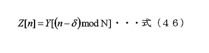
なお、Y[n]は、N個のサンプルで構成されるものとし(Nは2以上の整数)、したがって、nは0以上N-1以下の整数とする。 Note that Y[n] is made up of N samples (N is an integer of 2 or more), and therefore, n is an integer of 0 or more and N-1 or less.
次に、巡回遅延量と位相変更の関係について説明する。 Next, the relationship between the amount of cyclic delay and the phase change will be explained.
例えば、OFDMにCDD/CSDを適用する場合を考える。なお、OFDMを用いたときのキャリア配置は、図16のようにする。 For example, consider the case where CDD/CSD is applied to OFDM. Note that the carrier arrangement when using OFDM is as shown in FIG.
図16において、1601はシンボルであり、横軸を周波数(キャリア番号)とし、低い周波数から高い周波数へ、昇順にキャリアが配置されている。したがって、最も低い周波数のキャリアを「キャリア1」とすると、それにつづき「キャリア2」「キャリア3」「キャリア4」・・・と並んでいる。
In FIG. 16, 1601 is a symbol, the horizontal axis is the frequency (carrier number), and carriers are arranged in ascending order from low frequency to high frequency. Therefore, if the carrier with the lowest frequency is designated as "
そして、例えば、図2の位相変更部209Bにおいて、巡回遅延量τを与える。すると、「キャリアi」における位相変更値Ω[i]は、以下のようにあらわされる。
Then, for example, the

なお、μは、巡回遅延量、FFT(Fast Fourier Transform)サイズなどから求めることができる値である。 Note that μ is a value that can be obtained from the amount of cyclic delay, the FFT (Fast Fourier Transform) size, and the like.
そして、位相変更前(巡回遅延処理前)の「キャリアi」、時刻tのベースバンド信号をv’[i][t]とすると、位相変更後の「キャリアi」、時刻tの信号v[i][t]は、v[i] [t]=Ω[i]×v’[i][t]とあらわすことができる。 Then, if the baseband signal of "carrier i" before phase change (before cyclic delay processing) and time t is v'[i][t], then "carrier i" after phase change and the signal v[ of time t] i][t] can be expressed as v[i][t]=Ω[i]×v'[i][t].
(補足2)
当然であるが、本明細書において説明した実施の形態、その他の内容を複数組み合わせて、実施してもよい。
(Supplement 2)
Naturally, the embodiments described in this specification and other contents may be combined and implemented.
また、各実施の形態、その他の内容については、あくまでも例であり、例えば、「変調方式、誤り訂正符号化方式(使用する誤り訂正符号、符号長、符号化率等)、制御情報など」を例示していても、別の「変調方式、誤り訂正符号化方式(使用する誤り訂正符号、符号長、符号化率等)、制御情報など」を適用した場合でも同様の構成で実施することが可能である。 Furthermore, each embodiment and other contents are merely examples, and include, for example, "modulation method, error correction coding method (error correction code to be used, code length, coding rate, etc.), control information, etc." Although shown as an example, it is possible to implement the same configuration even if a different modulation method, error correction coding method (error correction code used, code length, coding rate, etc.), control information, etc. is applied. It is possible.
変調方式については、本開示で記載している変調方式以外の変調方式を使用しても、本開示において説明した実施の形態、その他の内容を実施することが可能である。例えば、APSK(Amplitude Phase Shift Keying)(例えば、16APSK, 64APSK, 128APSK, 256APSK, 1024APSK, 4096APSKなど)、PAM(Pulse Amplitude Modulation)(例えば、4PAM, 8PAM, 16PAM, 64PAM, 128PAM, 256PAM, 1024PAM, 4096PAMなど)、PSK(例えば、BPSK, QPSK, 8PSK, 16PSK, 64PSK, 128PSK, 256PSK, 1024PSK, 4096PSKなど)、QAM(Quadrature Amplitude Modulation)(例えば、4QAM, 8QAM, 16QAM, 64QAM, 128QAM, 256QAM, 1024QAM, 4096QAMなど)などを適用してもよいし、各変調方式において、均一マッピング、非均一マッピングとしてもよい。 Regarding the modulation method, even if a modulation method other than the modulation method described in this disclosure is used, it is possible to implement the embodiments described in this disclosure and other contents. For example, APSK (Amplitude Phase Shift Keying) (for example, 16APSK, 64APSK, 128APSK, 256APSK, 1024APSK, 4096APSK, etc.), PAM (Pulse Amplitude Modulation) (for example, 4PAM, 8PAM, 16PAM, 64PAM, 128PAM, 256PAM, 1024PAM, 4096PAM ), PSK (e.g., BPSK, QPSK, 8PSK, 16PSK, 64PSK, 128PSK, 256PSK, 1024PSK, 4096PSK, etc.), QAM (Quadrature Amplitude Modulation) (e.g., 4QAM, 8QAM, 16QAM, 64QAM, 128QAM, 256QAM, 1024 QAM, 4096QAM, etc.) may be applied, or uniform mapping or non-uniform mapping may be used for each modulation method.
また、I-Q平面における2個、4個、8個、16個、64個、128個、256個、1024個等の信号点の配置方法(2個、4個、8個、16個、64個、128個、256個、1024個等の信号点をもつ変調方式)は、本開示で示した変調方式の信号点配置方法に限ったものではない。したがって、複数のビットに基づき同相成分と直交成分を出力するという機能がマッピング部での機能となり、その後、プリコーディングおよび位相変更を施すことが本開示の一つの有効な機能となる。 Also, how to arrange signal points such as 2, 4, 8, 16, 64, 128, 256, 1024, etc. on the IQ plane (2, 4, 8, 16, The modulation method having 64, 128, 256, 1024, etc. signal points) is not limited to the signal point arrangement method of the modulation method shown in the present disclosure. Therefore, the function of outputting in-phase components and quadrature components based on a plurality of bits is a function of the mapping section, and thereafter, performing precoding and phase change is one effective function of the present disclosure.
そして、本開示において、「∀」「∃」が存在する場合、「∀」は全称記号(universal quantifier)をあらわしており、「∃」は存在記号(existential quantifier)をあらわしている。 In the present disclosure, when "∀" and "∃" exist, "∀" represents a universal quantifier, and "∃" represents an existential quantifier.
また、本開示において、複素平面がある場合、例えば、偏角のような、位相の単位は、「ラジアン(radian)」としている。 Furthermore, in the present disclosure, when there is a complex plane, the unit of phase, such as argument, is "radian".
複素平面を利用すると、複素数の極座標による表示として極形式で表示できる。複素数z = a + jb (a、bは実数であり、jは虚数単位である)に、複素平面上の点(a, b) を対応させたとき、この点が極座標で[r, θ] とあらわされるなら、
a=r×cosθ、b=r×sinθ
By using the complex plane, complex numbers can be displayed in polar form as represented by polar coordinates. When a point (a, b) on the complex plane is associated with a complex number z = a + jb (a, b are real numbers, j is an imaginary unit), this point is expressed as [r, θ] in polar coordinates. If it is expressed as
a=r×cosθ, b=r×sinθ

が成り立ち、r は z の絶対値 (r = |z|) であり、θ が偏角 (argument)となる。そして、z = a + jbは、r×e jθとあらわされる。 holds, r is the absolute value of z (r = |z|), and θ is the argument. Then, z = a + jb is expressed as r×e jθ .
本開示において、端末の受信装置とアンテナが別々となっている構成であってもよい。例えば、アンテナで受信した信号、または、アンテナで受信した信号に対し、周波数変換を施した信号を、ケーブルを通して、入力するインターフェースを受信装置が具備し、受信装置はその後の処理を行う。 In the present disclosure, a configuration may be adopted in which the receiving device and antenna of the terminal are separate. For example, a receiving device includes an interface that inputs a signal received by an antenna or a signal obtained by frequency-converting the signal received by the antenna through a cable, and the receiving device performs subsequent processing.
また、受信装置が得たデータ及び情報は、その後、映像や音に変換され、ディスプレイ(モニタ)に表示されたり、スピーカから音が出力されたりする。さらに、受信装置が得たデータ及び情報は、映像や音に関する信号処理が施され、受信装置が具備するRCA端子(映像端子、音用端子)、USB(Universal Serial Bus)、HDMI(登録商標)(High-Definition Multimedia Interface)、デジタル用端子等から出力されてもよい。なお、映像や音に関する信号処理を施さなくても、本開示の効果を得ることができる。 Further, the data and information obtained by the receiving device are then converted into images and sounds, which are displayed on a display (monitor), and sounds are output from a speaker. Furthermore, the data and information obtained by the receiving device are subjected to signal processing related to video and sound, and the receiving device is equipped with an RCA terminal (video terminal, audio terminal), USB (Universal Serial Bus), HDMI (registered trademark). (High-Definition Multimedia Interface), may be output from a digital terminal, etc. Note that the effects of the present disclosure can be obtained without performing signal processing regarding video and sound.
本開示において、送信装置を具備しているのは、例えば、放送局、基地局、アクセスポイント、端末、携帯電話(mobile phone)等の通信及び放送機器であることが考えられ、このとき、受信装置を具備しているのは、テレビ、ラジオ、端末、パーソナルコンピュータ、携帯電話、アクセスポイント、基地局等の通信機器であることが考えられる。また、本開示における送信装置、受信装置は、通信機能を有している機器であって、その機器が、テレビ、ラジオ、パーソナルコンピュータ、携帯電話等のアプリケーションを実行するための装置に何らかのインターフェースを解して接続できるような形態であることも考えられる。 In the present disclosure, communication and broadcasting equipment such as broadcasting stations, base stations, access points, terminals, and mobile phones may be equipped with transmitting devices, and in this case, It is conceivable that the devices include communication equipment such as televisions, radios, terminals, personal computers, mobile phones, access points, base stations, and the like. Further, the transmitting device and the receiving device in the present disclosure are devices that have a communication function, and the device has some kind of interface with a device for executing an application such as a television, radio, personal computer, or mobile phone. It is also conceivable that the configuration could be such that it could be connected by
また、本実施の形態では、データシンボル以外のシンボル、例えば、パイロットシンボル(プリアンブル、ユニークワード、ポストアンブル、リファレンスシンボル等)、制御情報用のシンボルなどが、フレームにどのように配置されていてもよい。そして、ここでは、パイロットシンボル、制御情報用のシンボルと名付けているが、どのような名付け方を行ってもよく、機能自身が重要となっている。 Furthermore, in this embodiment, symbols other than data symbols, such as pilot symbols (preamble, unique word, postamble, reference symbol, etc.), symbols for control information, etc., are arranged no matter how they are arranged in the frame. good. Although the symbols are named pilot symbols and control information symbols here, they can be named in any way, and the function itself is important.
パイロットシンボルは、例えば、送受信機において、PSK変調を用いて変調した既知のシンボルであればよく、受信機は、このシンボルを用いて、周波数同期、時間同期、(各変調信号の)チャネル推定(CSI(Channel State Information)の推定)、信号の検出等を行う。なお、受信機が同期することによって、受信機は、送信機が送信したパイロットシンボルを知ることができてもよい。 The pilot symbol may be, for example, a known symbol modulated using PSK modulation in the transceiver, and the receiver uses this symbol to perform frequency synchronization, time synchronization, and channel estimation (of each modulated signal). CSI (Channel State Information) estimation), signal detection, etc. Note that by synchronizing the receiver, the receiver may be able to know the pilot symbol transmitted by the transmitter.
また、制御情報用のシンボルは、データ(例えば、アプリケーション等のデータ)以外の通信を実現するための、通信相手に伝送する必要がある情報、例えば、通信に用いている変調方式及び誤り訂正符号化方式及び誤り訂正符号化方式の符号化率、上位レイヤーでの設定情報等を伝送するためのシンボルである。 In addition, symbols for control information include information that needs to be transmitted to the communication partner in order to realize communication other than data (for example, application data), such as the modulation method and error correction code used for communication. This is a symbol for transmitting the coding rate of the coding method and error correction coding method, setting information in the upper layer, etc.
なお、本開示は各実施の形態に限定されず、種々変更して実施することが可能である。例えば、各実施の形態では、通信装置として行う場合について説明しているが、これに限られるものではなく、この通信方法をソフトウェアとして行うことも可能である。 Note that the present disclosure is not limited to each embodiment, and can be implemented with various changes. For example, in each embodiment, a case is described in which the communication method is implemented as a communication device, but the communication method is not limited to this, and it is also possible to implement this communication method as software.
また、上記では、2つの変調信号を2つのアンテナから送信する方法におけるプリコーディング切り替え方法について説明したが、これに限ったものではなく、4つのマッピング後の信号に対し、プリコーディングを行い、4つの変調信号を生成し、4つのアンテナから送信する方法、つまり、N個のマッピング後の信号に対し、プリコーディングを行い、N個の変調信号を生成し、N個のアンテナから送信する方法においても同様にプリコーディングウェイト(プリコーディング行列)を変更する、プリコーディング切り替え方法としても同様に実施することができる。 In addition, although the above describes a precoding switching method in a method of transmitting two modulated signals from two antennas, the method is not limited to this, and precoding is performed on four mapped signals. In a method of generating two modulated signals and transmitting them from four antennas, that is, a method of precoding N mapped signals, generating N modulated signals, and transmitting them from N antennas. This method can also be similarly implemented as a precoding switching method that changes the precoding weight (precoding matrix).
本開示では、「プリコーディング」「プリコーディングウェイト」等の用語を用いているが、呼び方自身は、どのようなものでもよく、本開示では、その信号処理自身が重要となる。 In this disclosure, terms such as "precoding" and "precoding weight" are used, but any term may be used, and in this disclosure, the signal processing itself is important.
ストリームs1(t)、s2(t)により、異なるデータを伝送してもよいし、同一のデータを伝送してもよい。 The streams s1(t) and s2(t) may transmit different data or may transmit the same data.
送信装置の送信アンテナ、受信装置の受信アンテナ、共に、図面で記載されている1つのアンテナは、複数のアンテナにより構成されていても良い。 Both the transmitting antenna of the transmitting device and the receiving antenna of the receiving device, which are illustrated in the drawings, may be composed of a plurality of antennas.
送信装置は、受信装置に対し、送信方法(MIMO、SISO、時空間ブロック符号、インタリーブ方式)、変調方式、誤り訂正符号化方式を通知するが、送信装置が送信するフレームに存在する。受信装置は上記情報を得ることで、動作を変更する。 The transmitting device notifies the receiving device of the transmission method (MIMO, SISO, space-time block code, interleaving method), modulation method, and error correction encoding method, which are present in the frame transmitted by the transmitting device. The receiving device changes its operation by obtaining the above information.
なお、例えば、上記通信方法を実行するプログラムを予めROM(Read Only Memory)に格納しておき、そのプログラムをCPU(Central Processor Unit)によって動作させるようにしても良い。 Note that, for example, a program for executing the above communication method may be stored in advance in a ROM (Read Only Memory), and the program may be operated by a CPU (Central Processor Unit).
また、上記通信方法を実行するプログラムをコンピュータで読み取り可能な記憶媒体に格納し、記憶媒体に格納されたプログラムをコンピュータのRAM(Random Access Memory)に記録して、コンピュータをそのプログラムにしたがって動作させるようにしても良い。 Further, a program for executing the above communication method is stored in a computer-readable storage medium, the program stored in the storage medium is recorded in a RAM (Random Access Memory) of the computer, and the computer is operated according to the program. You can do it like this.
そして、上記の各実施の形態などの各構成は、典型的には集積回路であるLSI(Large Scale Integration)として実現されてもよい。これらは、個別に1チップ化されてもよいし、各実施の形態の全ての構成または一部の構成を含むように1チップ化されてもよい。 Each configuration of each of the embodiments described above may be realized as an LSI (Large Scale Integration), which is typically an integrated circuit. These may be individually integrated into one chip, or may be integrated into one chip so as to include all or part of the configuration of each embodiment.
ここでは、LSIとしたが、集積度の違いにより、IC(Integrated Circuit)、システムLSI、スーパーLSI、ウルトラLSIと呼称されることもある。また、集積回路化の手法はLSIに限られるものではなく、専用回路または汎用プロセッサで実現しても良い。LSI製造後に、プログラムすることが可能なFPGA(Field Programmable Gate Array)や、LSI内部の回路セルの接続や設定を再構成可能なリコンフィギュラブル プロセッサを利用しても良い。 Although it is referred to as an LSI here, it may also be called an IC (Integrated Circuit), system LSI, super LSI, or ultra LSI depending on the degree of integration. Moreover, the method of circuit integration is not limited to LSI, and may be implemented using a dedicated circuit or a general-purpose processor. It is also possible to use an FPGA (Field Programmable Gate Array) that can be programmed after the LSI is manufactured, or a reconfigurable processor that can reconfigure the connections and settings of circuit cells inside the LSI.
さらに、半導体技術の進歩又は派生する別技術によりLSIに置き換わる集積回路化の技術が登場すれば、当然、その技術を用いて機能ブロックの集積化を行っても良い。バイオ技術の適応等が可能性としてあり得る。 Furthermore, if an integrated circuit technology that replaces LSI emerges due to advancements in semiconductor technology or other derived technology, then of course the functional blocks may be integrated using that technology. Adaptation of biotechnology may be a possibility.
本開示は、複数のアンテナからそれぞれ異なる変調信号を送信する無線システムに広く適用できる。また、複数の送信箇所を持つ有線通信システム(例えば、PLC(Power Line Communication)システム、光通信システム、DSL(Digital Subscriber Line:デジタル加入者線)システム)において、MIMO伝送を行う場合についても適用することができる。 The present disclosure is widely applicable to wireless systems that transmit different modulated signals from a plurality of antennas. It also applies to MIMO transmission in wired communication systems with multiple transmission points (for example, PLC (Power Line Communication) systems, optical communication systems, DSL (Digital Subscriber Line) systems). be able to.
(実施の形態2)
本実施の形態では、実施の形態1における図2とは異なる構成の実施方法について説明する。
(Embodiment 2)
In this embodiment, a method of implementing a configuration different from that in FIG. 2 in
図1は、本実施の形態における例えば、基地局、アクセスポイント、放送局等の送信装置の構成の一例であり、詳細については、実施の形態1で説明したので、説明は省略する。
FIG. 1 shows an example of the configuration of a transmitting device such as a base station, an access point, a broadcast station, etc. in this embodiment, and since the details have been explained in
信号処理部106は、マッピング後の信号105_1、105_2、信号群110、制御信号100を入力とし、制御信号100に基づいて、信号処理を行い、信号処理後の信号106_A、106_Bを出力する。このとき、信号処理後の信号106_Aをu1(i)、信号処理後の信号106_Bをu2(i)とあらわす。iはシンボル番号であり、例えば、iは0以上の整数とする。なお、信号処理の詳細については、図18を用いて説明する。
The
図18は、図1における信号処理部106の構成の一例を示している。重み付け合成部(プリコーディング部)203は、マッピング後の信号201A(図1のマッピング後の信号105_1)、および、マッピング後の信号201B(図1のマッピング後の信号105_2)、および、制御信号200(図1の制御信号100)を入力とし、制御信号200に基づき重み付け合成(プリコーディング)を行い、重み付け後の信号204Aおよび重み付け後の信号204Bを出力する。このとき、マッピング後の信号201Aをs1(t)、マッピング後の信号201Bをs2(t)、重み付け後の信号204Aをz1(t)、重み付け後の信号204Bをz2’(t)とあらわす。なお、tは一例として、時間とする。s1(t)、s2(t)、z1(t)、z2’(t)は複素数で定義され、したがって、実数であってもよい。
FIG. 18 shows an example of the configuration of the
ここでは、時間の関数として扱っているが「周波数(キャリア番号)」の関数としてもよいし、「時間及び周波数」の関数としてもよい。また、「シンボル番号」の関数としてもよい。この点は、実施の形態1でも同様である。 Here, it is treated as a function of time, but it may also be a function of "frequency (carrier number)" or a function of "time and frequency." Alternatively, it may be a function of "symbol number". This point also applies to the first embodiment.
重み付け合成部(プリコーディング部)203は、式(1)の演算を行う。 The weighted synthesis unit (precoding unit) 203 performs the calculation of equation (1).
そして、位相変更部205Bは、重み付け合成後の信号204B、および、制御信号200を入力とし、制御信号200に基づき、重み付け合成後の信号204Bに対し、位相変更を施し、位相変更後の信号206Bを出力する。なお、位相変更後の信号206Bをz2(t)であらわし、z2(t)は複素数で定義し、実数であってもよい。
Then, the
位相変更部205Bの具体的動作について説明する。位相変更部205Bでは、例えば、z2’(i)に対しy(i)の位相変更を施す。したがって、z2(i)=y(i)×z2’(i)とあらわすことができる。iはシンボル番号であり、iは0以上の整数である。
The specific operation of the
例えば、位相変更の値を式(2)のように設定する。Nは2以上の整数であり、Nは位相変更の周期である。なお、Nは3以上の奇数に設定するとデータの受信品質が向上する可能性がある。ただし、式(2)は、あくまでも例であり、これに限ったものではない。そこで、位相変更値y(i)=ej×δ(i)であらわす。 For example, the phase change value is set as shown in equation (2). N is an integer greater than or equal to 2, and N is the period of phase change. Note that if N is set to an odd number of 3 or more, the data reception quality may improve. However, formula (2) is just an example, and is not limited to this. Therefore, the phase change value is expressed as y(i)=e j×δ(i) .
このときz1(i)およびz2(i)は式(3)であらわすことができる。なお、δ(i)は実数である。そして、z1(i)とz2(i)は、同一時間、同一周波数(同一周波数帯)で、送信装置から送信される。式(3)において、位相変更の値は、式(2)に限ったものではなく、例えば、周期的、規則的に位相を変更するような方法が考えられる。 At this time, z1(i) and z2(i) can be expressed by equation (3). Note that δ(i) is a real number. Then, z1(i) and z2(i) are transmitted from the transmitting device at the same time and at the same frequency (same frequency band). In Equation (3), the value of the phase change is not limited to Equation (2), and for example, a method of periodically and regularly changing the phase can be considered.
そして、実施の形態1で説明したように、式(1)および式(3)における(プリコーディング)行列としては、式(5)から式(36)までなどが考えられる。ただし、プリコーディング行列はこれらに限ったものではなく、実施の形態1についても同様である。
As described in
挿入部207Aは、重み付け合成後の信号204A、パイロットシンボル信号pa(t)251A、プリアンブル信号252、制御情報シンボル信号253、制御信号200を入力とし、制御信号200に含まれるフレーム構成の情報に基づき、フレーム構成に基づいたベースバンド信号208Aを出力する。なお、tは時間を表す。
The
同様に、挿入部207Bは、位相変更後の信号206B、パイロットシンボル信号pb(t)251B、プリアンブル信号252、制御情報シンボル信号253、制御信号200を入力とし、制御信号200に含まれるフレーム構成の情報に基づき、フレーム構成に基づいたベースバンド信号208Bを出力する。
Similarly, the inserting
位相変更部209Aは、ベースバンド信号208A、および、制御信号200を入力とし、ベースバンド信号208Aに対し、制御信号200に基づいて、位相変更を行い、位相変更後の信号210Aを出力する。ベースバンド信号208Aをシンボル番号iの関数とし、x’(i)とあらわす。すると、位相変更後の信号210A(x(i))は、x(i)=ej×ε(i)×x’(i)とあらわすことができる。iは0以上の整数であり、jは虚数単位である。
The
なお、実施の形態1等で説明したように、位相変更部209Aの動作としては、非特許文献2、非特許文献3で記載されているCDD/CSDであってもよい。そして、位相変更部209Aは、周波数軸方向に存在するシンボルに対し、位相変更を行う。つまり、位相変更部209Aは、データシンボル、パイロットシンボル、制御情報シンボルなどに対し位相変更を施す。
Note that, as described in
図3は、図1の無線部107_A、107_Bの構成の一例であり、図4は、図1の送信信号108_Aのフレーム構成であり、図5は、図1の送信信号108_Bのフレーム構成であり、実施の形態1で詳細の説明を行ったので、説明は省略する。
3 shows an example of the configuration of the wireless sections 107_A and 107_B in FIG. 1, FIG. 4 shows the frame structure of the transmission signal 108_A in FIG. 1, and FIG. 5 shows the frame structure of the transmission signal 108_B in FIG. , the detailed explanation was given in
図4のキャリアA、時刻$Bにシンボルが存在し、図5のキャリアA、時刻$Bにシンボルが存在したとき、図4のキャリアA、時刻$Bのシンボルと図5のキャリアA、時刻$Bのシンボルは、同一時間、同一周波数に送信される。なお、フレーム構成については、図4、図5に限ったものではなく、あくまでも、図4、図5はフレーム構成の例である。 When a symbol exists at carrier A, time $B in FIG. 4, and a symbol exists at carrier A, time $B in FIG. 5, the symbol at carrier A, time $B in FIG. The $B symbols are transmitted at the same time and on the same frequency. Note that the frame configuration is not limited to those shown in FIGS. 4 and 5, and FIGS. 4 and 5 are merely examples of frame configurations.
そして、図4、図5におけるその他のシンボルは、「図2におけるプリアンブル信号252、制御情報シンボル信号253」に相当するシンボルであり、したがって、図4のその他のシンボル403と同一時刻、かつ、同一周波数(同一キャリア)の図5のその他のシンボル503は、制御情報を伝送している場合、同一のデータ(同一の制御情報)を伝送している。
The other symbols in FIGS. 4 and 5 are symbols corresponding to "the
なお、図4のフレームと図5のフレームを受信装置は同時に受信することを想定しているが、図4のフレーム、または、図5のフレームを受信しても受信装置は送信装置が送信したデータを得ることは可能である。 It is assumed that the receiving device receives the frame in FIG. 4 and the frame in FIG. 5 at the same time, but even if the receiving device receives the frame in FIG. 4 or the frame in FIG. It is possible to obtain data.
図6は、図2の制御情報信号253を生成するための制御情報生成に関する部分の構成の一例を示しており、実施の形態1で詳細の説明を行ったので、説明は省略する。 FIG. 6 shows an example of the configuration of a portion related to control information generation for generating the control information signal 253 of FIG. 2, and since the details were explained in the first embodiment, the explanation will be omitted.
図7は、図1のアンテナ部#A 109_A、アンテナ部#B 109_Bの構成の一例を示す。図7は、アンテナ部#A 109_A、アンテナ部#B 109_Bが複数のアンテナで構成されている例であり、実施の形態1で詳細の説明を行ったので、説明は省略する。
FIG. 7 shows an example of the configuration of antenna section #A 109_A and antenna section #B 109_B in FIG. 1. FIG. 7 shows an example in which the antenna section #A 109_A and the antenna section #B 109_B are composed of a plurality of antennas, and since the detailed explanation was given in
図8は、図1の送信装置が、例えば、図4、図5のフレーム構成の送信信号を送信したとき、その変調信号を受信する受信装置の構成の一例を示しており、実施の形態1で詳細の説明を行ったので、説明は省略する。 FIG. 8 shows an example of the configuration of a receiving device that receives a modulated signal when the transmitting device of FIG. 1 transmits a transmission signal having the frame structure of FIGS. 4 and 5, for example. Since the details have been explained in , the explanation will be omitted.
図10は、図8のアンテナ部#X 801X、アンテナ部#Y 801Yの構成の一例を示している。図10は、アンテナ部#X 801X、アンテナ部#Y 801Yが複数アンテナで構成されている例であり、実施の形態1で詳細の説明を行ったので、説明は省略する。
FIG. 10 shows an example of the configuration of antenna
次に、図1のように送信装置の信号処理部106が、図18に示すように、位相変更部205Bと位相変更部209Aを挿入している。その特徴と、そのときの効果について説明する。
Next, as shown in FIG. 1, the
図4、図5を用いて説明したように、第1の系列を用いてマッピングすることによって得られたマッピング後の信号s1(i)201Aと第2の系列を用いてマッピングすることによって得られたマッピング後の信号s2(i)201Bに対し、プリコーディング(重み付け合成)を施し、得られた重み付け合成後の信号204A、204Bのうちの一方に対して、位相変更を行っているのが、位相変更部205Bである。iはシンボル番号であり、iは0以上の整数とする。
As explained using FIGS. 4 and 5, the mapped signal s1(i) 201A obtained by mapping using the first sequence and the mapped signal s1(i) 201A obtained by mapping using the second sequence The precoding (weighted combination) is performed on the mapped signal s2(i) 201B, and the phase is changed on one of the obtained weighted and combined
そして、重み付け合成後の信号204Aと位相変更後の信号206Bは、同一周波数、同一時間に送信される。したがって、図4、図5において、図5のデータシンボル502に対して、位相変更を施す。図18では、位相変更部205は、重み付け合成後の信号204Bに対して施しているため、図5のデータシンボル502に対して位相変更を施している。重み付け合成後の信号204Aに対して位相変更を施す場合は、図4のデータシンボル402に対して位相変更を施す。この点については、後で説明する。
The weighted and combined
例えば、図11は、図5のフレームに対し、キャリア1からキャリア5、時刻$4から時刻$6を抽出したものである。なお、図5と同様、パイロットシンボル501、データシンボル502、その他のシンボル503を示す。
For example, FIG. 11
上述のように、図11に示したシンボルにおいて、(キャリア1、時刻$5)、(キャリア2、時刻$5)、(キャリア3、時刻$5)、(キャリア4、時刻$5)、(キャリア5、時刻$5)、(キャリア1、時刻$6)、(キャリア2、時刻$6)、(キャリア4、時刻$6)、及び、(キャリア5、時刻$6)におけるデータシンボルに対し、位相変更部205Bは位相変更を施す。
As mentioned above, in the symbols shown in FIG. 11, (
よって、図11に示したデータシンボルに対する位相変更値を、(キャリア1、時刻$5)では「ej×δ15(i)」とし、(キャリア2、時刻$5)では「ej×δ25(i)」とし、(キャリア3、時刻$5)では「ej×δ35(i)」とし、(キャリア4、時刻$5)では「ej×δ45(i)」とし、(キャリア5、時刻$5)では「ej×δ55(i)」とし、(キャリア1、時刻$6)では「ej×δ16(i)」とし、(キャリア2、時刻$6)では「ej×δ26(i)」とし、(キャリア4、時刻$6)では「ej×δ46(i)」とし、(キャリア5、時刻$6)では「ej×δ56(i)」とする。
Therefore, the phase change value for the data symbol shown in FIG. 11 is set to "e j × δ15(i) " at (
一方、図11に示したシンボルにおいて、(キャリア1、時刻$4)、(キャリア2、時刻$4)、(キャリア3、時刻$4)、(キャリア4、時刻$4)、及び、(キャリア5、時刻$4)におけるその他のシンボル、(キャリア3、時刻$6)におけるパイロットシンボルは、位相変更部205Bの位相変更の対象ではない。
On the other hand, in the symbols shown in FIG. 11, (
この点が位相変更部205Bの特徴的な点である。なお、図11における位相変更の対象である、(キャリア1、時刻$5)、(キャリア2、時刻$5)、(キャリア3、時刻$5)、(キャリア4、時刻$5)、(キャリア5、時刻$5)、(キャリア1、時刻$6)、(キャリア2、時刻$6)、(キャリア4、時刻$6)、及び、(キャリア5、時刻$6)におけるデータシンボルと「同一キャリア、同一時刻」には、図4では、データキャリアが配置されている。
This point is a characteristic point of the
つまり、図4において、(キャリア1、時刻$5)、(キャリア2、時刻$5)、(キャリア3、時刻$5)、(キャリア4、時刻$5)、(キャリア5、時刻$5)、(キャリア1、時刻$6)、(キャリア2、時刻$6)、(キャリア4、時刻$6)、及び、(キャリア5、時刻$6)はデータシンボルである。
That is, in FIG. 4, (
つまり、複数のストリームを伝送するMIMO伝送を行っているデータシンボルが位相変更部205Bの位相変更の対象である。
In other words, data symbols performing MIMO transmission that transmits a plurality of streams are subject to phase change by the
なお、位相変更部205Bがデータシンボルに施す位相変更の例として、式(2)のように、データシンボルに、規則的な位相変更、周期Nの位相変更を行う方法がある。ただし、データシンボルに施す位相変更方法は、これに限ったものではない。
Note that, as an example of the phase change that the
このようにすることで、直接波が支配的な環境、例えば、LOS環境のときに、複数のストリームを伝送しているMIMO伝送を行っているデータシンボルの受信装置におけるデータの受信品質が向上するという効果を得ることができる。この効果について、説明を行う。 By doing so, in an environment where direct waves are dominant, for example, a LOS environment, the data reception quality in a data symbol receiving device that is performing MIMO transmission that transmits multiple streams is improved. This effect can be obtained. This effect will be explained.
例えば、図1のマッピング部104で使用する変調方式がQPSKである。図18のマッピング後の信号201AはQPSKの信号であり、また、マッピング後の信号201BもQPSKの信号となる。つまり、2つのQPSKのストリームを送信する。
For example, the modulation method used by
すると、図8の信号処理部811では、例えば、チャネル推定信号806_1、806_2を用いて、16個の候補信号点を得る。QPSKは2ビットを伝送でき、2ストリームにより、計4ビットを伝送する。よって、24=16個の候補信号点が存在する。なお、チャネル推定信号808_1、808_2を用いて、別の16個の候補信号点を得ることにもなるが、説明は同様となるため、チャネル推定信号806_1、806_2を用いて得られる16個の候補信号点について、焦点をあて、説明を進める。
Then, the
このときの状態の一例を図12に示す。図12A、図12B、いずれも横軸は同相I、縦軸は直交Qであり、同相I-直交Q平面において、16個の候補信号点が存在する。16個の候補信号点のうち、一つが、送信装置が送信した信号点である。このため、「16個の候補信号点」と呼ぶ。 An example of the state at this time is shown in FIG. In both FIGS. 12A and 12B, the horizontal axis is in-phase I, and the vertical axis is quadrature Q, and there are 16 candidate signal points in the in-phase I-quadrature Q plane. One of the 16 candidate signal points is a signal point transmitted by the transmitting device. Therefore, they are called "16 candidate signal points."
直接波が支配的な環境、例えば、LOS環境のとき、第1のケースとして、「図18の位相変更部205Bが存在しない場合、つまり、図18の位相変更部205Bによる位相変更を行わない場合」を考える。
In an environment where direct waves are dominant, for example, a LOS environment, the first case is ``when the
「第1のケース」の場合、位相変更が行われないため、図12Aのような状態に陥る可能性がある。図12Aの状態に陥った場合、「信号点1201と1202」、「信号点1203、1204、1205、1206」、「信号点1207、1208」のように、信号点が密の部分が存在するため、図8の受信装置において、データの受信品質が低下する可能性がある。
In the "first case", no phase change is performed, so there is a possibility of falling into a state as shown in FIG. 12A. In the case of the state shown in FIG. 12A, there are parts with dense signal points, such as "
この現象を克服するために、図18において、位相変更部205Bを挿入している。位相変更部205Bを挿入すると、シンボル番号iにより、図12Aのように「信号点が密の部分」が存在するシンボル番号と、図12Bのように「信号点間の距離が長い」というシンボル番号とが混在する。この状態に対し、誤り訂正符号を導入しているため、高い誤り訂正能力を得ることができ、図8の受信装置において、高いデータ受信品質を得ることができる。
In order to overcome this phenomenon, a
なお、図18において、パイロットシンボル、プリアンブルなど、データシンボルを復調(検波)するための、チャネル推定を行うための「パイロットシンボル、プリアンブル」に対し、図18の位相変更部205Bにおいて、位相変更を行わない。これにより、データシンボルにおいて、「シンボル番号iにより、図12Aのように「信号点が密の部分」が存在するシンボル番号と、図12Bのように「信号点間の距離が長い」というシンボル番号とが混在すること」を実現することができる。
In addition, in FIG. 18, the
ただし、パイロットシンボル、プリアンブルなど、データシンボルを復調(検波)するための、チャネル推定を行うための「パイロットシンボル、プリアンブル」に対し、図18の位相変更部205Bにおいて、位相変更を行っても、「データシンボルにおいて、「シンボル番号iにより、図12Aのように「信号点が密の部分」が存在するシンボル番号と、図12Bのように「信号点間の距離が長い」というシンボル番号とが混在すること」を実現することができる」場合がある。
However, even if the
この場合、パイロットシンボル、プリアンブルに対し、何らかの条件を付加して、位相変更を行わなければならない。例えば、データシンボルに対する位相変更の規則とは別の規則を設けて、「パイロットシンボル、および/または、プリアンブルに対し位相変更を施す」という方法が考えられる。例として、データシンボルに対し規則的に周期Nの位相変更を施し、パイロットシンボル、および/または、プリアンブルに対し規則的に周期Mの位相変更を施す、という方法がある。N、Mは2以上の整数となる。 In this case, it is necessary to add some conditions to the pilot symbols and preamble to change the phase. For example, a method can be considered in which a rule different from the phase change rule for data symbols is provided, and the phase is changed for pilot symbols and/or preambles. As an example, there is a method in which data symbols are regularly subjected to a phase change with a period of N, and pilot symbols and/or preambles are regularly subjected to a phase change with a period of M. N and M are integers of 2 or more.
前述より、位相変更部209Aは、ベースバンド信号208A、および、制御信号200を入力とし、ベースバンド信号208Aに対し、制御信号200に基づいて、位相変更を行い、位相変更後の信号210Aを出力する。ベースバンド信号208Aをシンボル番号iの関数とし、x’(i)とあらわす。すると、位相変更後の信号210A(x(i))は、x(i)=ej×ε(i)×x’(i)とあらわすことができる。iは0以上の整数であり、jは虚数単位である。
As described above, the
そして、位相変更部209Aの動作としては、非特許文献2、非特許文献3で記載されているCDD/CSDであってもよい。そして、位相変更部209Aは、周波数軸方向に存在するシンボルに対し、位相変更を行う。位相変更部209Aは、データシンボル、パイロットシンボル、制御情報シンボルなどに対し位相変更を施す。したがって、このケースの場合、シンボル番号iの対象となるシンボルは、データシンボル、パイロットシンボル、制御情報シンボル、プリアンブル(その他のシンボル)などとなる。
The operation of the
図18では、位相変更部209Aは、ベースバンド信号208Aに対して位相変更を施しているため、図4に記載されている各シンボルに対して位相変更を施す。
In FIG. 18, the
したがって、図4のフレームにおいて、時刻$1の全てのキャリアの全てのシンボル(その他のシンボル403)に対して、図18の位相変更部209Aは、位相変更を施す。
Therefore, in the frame of FIG. 4, the
同様に、図18の位相変更部209Aは、下記のシンボルに対し、位相変更を施す
「時刻$2の全てのキャリアの全てのシンボル(その他のシンボル403)」、
「時刻$3の全てのキャリアの全てのシンボル(その他のシンボル403)」、
「時刻$4の全てのキャリアの全てのシンボル(その他のシンボル403)」、
「時刻$5の全てのキャリアの全てのシンボル(パイロットシンボル401、または、データシンボル402)」、
「時刻$6の全ての全てのキャリアの全てのシンボル(パイロットシンボル401、または、データシンボル402)」、
「時刻$7の全てのキャリアの全てのシンボル(パイロットシンボル401、または、データシンボル402)」、
「時刻$8の全てのキャリアの全てのシンボル(パイロットシンボル401、または、データシンボル402)」、
「時刻$9の全てのキャリアの全てのシンボル(パイロットシンボル401、または、データシンボル402)」、
「時刻$10の全てのキャリアの全てのシンボル(パイロットシンボル401、または、データシンボル402)」、
「時刻$11の全てのキャリアの全てのシンボル(パイロットシンボル401、または、データシンボル402)」、以後の記載は省略する。
Similarly, the
"All symbols of all carriers at time $3 (other symbols 403)",
"All symbols of all carriers at time $4 (other symbols 403)",
"All symbols of all carriers at time $5 (pilot symbol 401 or data symbol 402)",
"All symbols of all carriers at time $6 (pilot symbol 401 or data symbol 402)",
"All symbols of all carriers at time $7 (pilot symbol 401 or data symbol 402)",
"All symbols of all carriers at time $8 (pilot symbol 401 or data symbol 402)",
"All symbols of all carriers at time $9 (pilot symbol 401 or data symbol 402)",
"All symbols of all carriers at time $10 (pilot symbol 401 or data symbol 402)",
"All symbols of all carriers at time $11 (pilot symbol 401 or data symbol 402)", the subsequent description will be omitted.
図13は、図1の送信信号108_Aの図4とは異なるフレーム構成であり、実施の形態1において、詳細の説明を行ったので、説明を省略する。
FIG. 13 shows a frame structure of the transmission signal 108_A in FIG. 1 that is different from that in FIG. 4, and since the detailed explanation was given in
図14は、図1の送信信号108_Bの図5とは異なるフレーム構成であり、実施の形態1において、詳細の説明を行ったので、説明を省略する。 FIG. 14 shows a frame structure of the transmission signal 108_B in FIG. 1 that is different from that in FIG. 5, and since the detailed explanation was given in the first embodiment, the explanation will be omitted.
図13のキャリアA、時刻$Bにシンボルが存在し、図14のキャリアA、時刻$Bにシンボルが存在したとき、図13のキャリアA、時刻$Bのシンボルと図14のキャリアA、時刻$Bのシンボルは、同一時間、同一周波数に送信される。なお、図13、図14のフレーム構成は、あくまでも例である。 When a symbol exists at carrier A, time $B in FIG. 13, and a symbol exists at carrier A, time $B in FIG. 14, the symbol at carrier A, time $B in FIG. The $B symbols are transmitted at the same time and on the same frequency. Note that the frame configurations in FIGS. 13 and 14 are merely examples.
そして、図13、図14におけるその他のシンボルは、「図18におけるプリアンブル信号252、制御情報シンボル信号253」に相当するシンボルであり、したがって、図13のその他のシンボル403と同一時刻、かつ、同一周波数(同一キャリア)の図14のその他のシンボル503は、制御情報を伝送している場合、同一のデータ(同一の制御情報)を伝送している。
The other symbols in FIGS. 13 and 14 are symbols corresponding to "the
なお、図13のフレームと図14のフレームを受信装置は同時に受信することを想定しているが、図13のフレーム、または、図14のフレームを受信しても受信装置は送信装置が送信したデータを得ることは可能である。 Note that although it is assumed that the receiving device receives the frame in FIG. 13 and the frame in FIG. 14 at the same time, even if the receiving device receives the frame in FIG. 13 or the frame in FIG. It is possible to obtain data.
位相変更部209Aは、ベースバンド信号208A、および、制御信号200を入力とし、ベースバンド信号208Aに対し、制御信号200に基づいて、位相変更を行い、位相変更後の信号210Aを出力する。ベースバンド信号208Aをシンボルシンボル番号iの関数とし、x’(i)とあらわす。iは0以上の整数である。
The
すると、位相変更後の信号210A(x(i))は、x(i)=ej×ε(i)×x’(i)とあらわすことができる。(jは虚数単位)そして、位相変更部209Aの動作としては、非特許文献2、非特許文献3で記載されているCDD/CSDであってもよい。そして、位相変更部209Aは、周波数軸方向に存在するシンボルに対し、位相変更を行う。位相変更部209Aは、データシンボル、パイロットシンボル、制御情報シンボルなどに対し位相変更を施す。
Then, the phase-changed
このとき、ヌルシンボルも位相変更の対象と考えることができる。したがって、このケースの場合、シンボル番号iの対象となるシンボルは、データシンボル、パイロットシンボル、制御情報シンボル、プリアンブル(その他のシンボル)、ヌルシンボルなどとなる。 At this time, the null symbol can also be considered as a phase change target. Therefore, in this case, the symbols targeted by symbol number i are data symbols, pilot symbols, control information symbols, preambles (other symbols), null symbols, and the like.
しかし、ヌルシンボルは、同相成分Iがゼロ(0)、かつ、直交成分Qがゼロ(0)であるため、ヌルシンボルに対し位相変更を行っても位相変更前の信号と位相変更後の信号は同じである。したがって、ヌルシンボルは位相変更の対象でないと解釈することも可能である。図18の場合、位相変更部209Aは、ベースバンド信号208Aに対して位相変更を施しているため、図13に記載されている各シンボルに対して位相変更を施す。
However, since the null symbol has an in-phase component I of zero (0) and a quadrature component Q of zero (0), even if the phase of the null symbol is changed, the signal before the phase change and the signal after the phase change are the same. Therefore, it is also possible to interpret the null symbol as not being subject to phase change. In the case of FIG. 18, the
したがって、図13のフレームにおいて、時刻$1の全てのキャリアの全てのシンボル(その他のシンボル403)に対し、図18の位相変更部209Aは、位相変更を施す。ただし、ヌルシンボル1301の位相変更の扱いについては前に説明したとおりである。
Therefore, in the frame of FIG. 13, the
同様に、図18の位相変更部209Aは、下記のシンボルに対し、位相変更を施す。
「時刻$2の全てのキャリアの全てのシンボルに対し(その他のシンボル403)」
「時刻$3の全てのキャリアの全てのシンボルに対し(その他のシンボル403)」
「時刻$4の全てのキャリアの全てのシンボルに対し(その他のシンボル403)」
「時刻$5の全てのキャリアの全てのシンボルに対し(パイロットシンボル401、または、データシンボル402)」
「時刻$6の全てのキャリアの全てのシンボルに対し(パイロットシンボル401、または、データシンボル402)」
「時刻$7の全てのキャリアの全てのシンボルに対し(パイロットシンボル401、または、データシンボル402)」
「時刻$8の全てのキャリアの全てのシンボルに対し(パイロットシンボル401、または、データシンボル402)」
「時刻$9の全てのキャリアの全てのシンボルに対し(パイロットシンボル401、または、データシンボル402)」
「時刻$10の全てのキャリアの全てのシンボルに対し(パイロットシンボル401、または、データシンボル402)」
「時刻$11の全てのキャリアの全てのシンボルに対し(パイロットシンボル401、または、データシンボル402)」
以後の時刻においては、記載を省略する。
Similarly, the
“For all symbols of all carriers at time $2 (other symbols 403)”
“For all symbols of all carriers at time $3 (other symbols 403)”
“For all symbols of all carriers at time $4 (other symbols 403)”
“For all symbols of all carriers at time $5 (pilot symbol 401 or data symbol 402)”
“For all symbols of all carriers at time $6 (pilot symbol 401 or data symbol 402)”
“For all symbols of all carriers at time $7 (pilot symbol 401 or data symbol 402)”
“For all symbols of all carriers at time $8 (pilot symbol 401 or data symbol 402)”
“For all symbols of all carriers at time $9 (pilot symbol 401 or data symbol 402)”
“For all symbols of all carriers at time $10 (pilot symbol 401 or data symbol 402)”
“For all symbols of all carriers at time $11 (pilot symbol 401 or data symbol 402)”
Descriptions of subsequent times will be omitted.
ただし、上記の記載において、ヌルシンボル1301の位相変更の扱いについては前に説明したとおりである。他の時刻及びキャリアについて記載は省略する。 However, in the above description, the handling of the phase change of the null symbol 1301 is as described above. Descriptions of other times and carriers will be omitted.
位相変更部209Aにおける位相変更値をΩ(i)とあらわす。ベースバンド信号208Aはx’(i)であり、位相変更後の信号210Aはx(i)である。したがって、x(i)=Ω(i)×x’(i)が成立する。
The phase change value in the
例えば、位相変更の値を式(38)と設定する。Qは2以上の整数であり、Qは位相変更の周期となる。jは虚数単位である。ただし、式(38)は、あくまでも例であり、これに限ったものではない。 For example, the value of phase change is set as equation (38). Q is an integer of 2 or more, and Q is the period of phase change. j is an imaginary unit. However, equation (38) is just an example and is not limited to this.
例えば、周期Qを持つように位相変更を行うようにΩ(i)を設定してもよい。 For example, Ω(i) may be set to change the phase so that it has a period Q.
また、例えば、図4、図13において、同一キャリアに対して、同一の位相変更値を与え、キャリアごとに位相変更値を設定するとしてもよい。例えば、以下のようになる。
・図4、図13におけるキャリア1に対し、時刻によらず、位相変更値を式(39)とする。
・図4、図13におけるキャリア2に対し、時刻によらず、位相変更値を式(40)とする。
・図4、図13におけるキャリア3に対し、時刻によらず、位相変更値を式(41)とする。
・図4、図13におけるキャリア4に対し、時刻によらず、位相変更値を式(42)とする。他のキャリアについては記載を省略する。
Further, for example, in FIGS. 4 and 13, the same phase change value may be given to the same carrier, and the phase change value may be set for each carrier. For example, as follows.
- For
- For
- For
- For
以上が、図18の位相変更部209Aの動作例となる。
The above is an example of the operation of the
図18の位相変更部209Aにより得られる効果について説明する。
The effects obtained by the
「図4および図5のフレーム」、または、「図13および図14のフレーム」のその他のシンボル403、503には、制御情報シンボルが含まれている。前述より、その他のシンボル403と同一時刻、かつ、同一の周波数(同一のキャリア)の図5のその他のシンボル503は、制御情報を伝送している場合、同一データ(同一の制御情報)を送信している。 Other symbols 403 and 503 of the "frames in FIGS. 4 and 5" or the "frames in FIGS. 13 and 14" include control information symbols. As mentioned above, if the other symbol 503 in FIG. 5 at the same time and the same frequency (same carrier) as the other symbol 403 is transmitting control information, it transmits the same data (same control information). are doing.
ところで、ケース2として、「制御情報シンボルを、図1のアンテナ部#A 109_A、または、アンテナ部#B 109_Bのいずれか一方のアンテナ部を用いて送信する」を考える。
By the way, as a
「ケース2」のように送信した場合、制御情報シンボルを送信するアンテナ数が1のため、「アンテナ部#A 109_Aとアンテナ部#B 109_Bの両者を用いて制御情報シンボルを送信する」場合と比較して、空間ダイバーシチのゲインが小さくなるため、「ケース2」では、図8の受信装置で受信してもデータの受信品質が低下する。したがって、データの受信品質の向上という点では、「アンテナ部#A 109_Aとアンテナ部#B 109_Bの両者を用いて制御情報シンボルを送信する」ほうがよい。
When transmitting as in "
ケース3として、「制御情報シンボルを、図1のアンテナ部#A 109_Aとアンテナ部#B 109_Bの両者を用いて送信する。ただし、図18における位相変更部209Aで位相変更を行わない」を考える。
As
「ケース3」のように送信した場合、アンテナ部#A 109_Aから送信した変調信号とアンテナ部#B 109_Bから送信した変調信号が同一である、または、特定の位相のずれがあるため、電波の伝搬環境によっては、図8の受信装置は、非常に劣悪な受信信号になる可能性があり、両者の変調信号が同一のマルチパスの影響を受ける可能性がある。これにより、図8の受信装置において、データの受信品質が低下するという現象がある。
When transmitting as in “
この現象を軽減するために、図18において、位相変更部209Aを設けている。これにより、時間、または、周波数方向で、位相を変更しているため、図8の受信装置において、劣悪な受信信号となる可能性を低減することができる。また、アンテナ部#A 109_Aから送信した変調信号が受けるマルチパスの影響とアンテナ部#B 109_Bから送信した変調信号が受けるマルチパスの影響に違いがある可能性が高いため、ダイバーシチゲインが得られる可能性が高く、これにより、図8の受信装置において、データの受信品質が向上する。
In order to alleviate this phenomenon, a
以上の理由から、図18において、位相変更部209Aを設け、位相変更を施している。
For the above reasons, in FIG. 18, a
その他のシンボル403、および、その他のシンボル503には、制御情報シンボル以外に、例えば、信号検出のためシンボル、周波数同期及び時間同期を行うためのシンボル、チャネル推定のためのシンボルが、制御情報シンボルを復調及び復号するために含まれいてる。また、「図4および図5のフレーム」、または、「図13および図14のフレーム」には、パイロットシンボル401、501が含まれており、これらを用いることで、制御情報シンボルをより高精度に復調及び復号を行うことが可能となる。 Other symbols 403 and other symbols 503 include, in addition to control information symbols, symbols for signal detection, symbols for frequency synchronization and time synchronization, symbols for channel estimation, and control information symbols. included for demodulating and decoding. In addition, the "frames in FIGS. 4 and 5" or "frames in FIGS. 13 and 14" include pilot symbols 401 and 501, and by using these, control information symbols can be converted with higher accuracy. It becomes possible to perform demodulation and decoding.
そして、「図4および図5のフレーム」、または、「図13および図14のフレーム」には、データシンボル402、および、データシンボル502により、同一周波数(周波数帯)、同一時間を用いて、複数のストリームを伝送しているMIMO伝送を行っている。これらのデータシンボルを復調するためには、その他のシンボル403、および、その他のシンボル503に含まれている、信号検出のためのシンボル、周波数同期及び時間同期を行うためのシンボル、チャネル推定のためのシンボルを用いる。 The "frames in FIGS. 4 and 5" or the "frames in FIGS. 13 and 14" use the same frequency (frequency band) and the same time using the data symbol 402 and the data symbol 502. MIMO transmission is being performed that transmits multiple streams. In order to demodulate these data symbols, other symbols 403 and 503 include symbols for signal detection, symbols for frequency synchronization and time synchronization, and symbols for channel estimation. Use the symbol.
このとき、「その他のシンボル403、および、その他のシンボル503に含まれている、信号検出のためのシンボル、周波数同期及び時間同期を行うためのシンボル、チャネル推定のためのシンボル」は、前述より、位相変更部209Aにより、位相変更を行っている。
At this time, "symbols for signal detection, symbols for performing frequency synchronization and time synchronization, and symbols for channel estimation included in other symbols 403 and other symbols 503" are as follows from the above. , the phase is changed by the
そのような状況の中、データシンボル402、および、データシンボル502に対し(上述の説明の場合は、データシンボル402に対し)、この処理を反映させず、受信装置において、データシンボル402、および、データシンボル502を復調及び復号する場合、位相変更部209Aで行った位相変更に対する処理を反映させた復調及び復号を行う必要があり、その処理は複雑となる可能性が高い。
In such a situation, this processing is not reflected on the data symbol 402 and the data symbol 502 (in the case of the above explanation, on the data symbol 402), and the receiving device transmits the data symbol 402 and the data symbol 502. When demodulating and decoding the data symbol 502, it is necessary to perform demodulation and decoding that reflect the process for the phase change performed by the
「その他のシンボル403、および、その他のシンボル503に含まれている、信号検出のためのシンボル、周波数同期及び時間同期を行うためのシンボル、チャネル推定のためのシンボル」は、位相変更部209Aにより、位相変更を行っているためである。
“Symbols for signal detection, symbols for performing frequency synchronization and time synchronization, and symbols for channel estimation, which are included in other symbols 403 and other symbols 503” are processed by the
しかし、図18に示すように、位相変更部209Aにおいて、データシンボル402、および、データシンボル502に対し(上述の説明の場合は、データシンボル402に対し)、位相変更を施した場合、受信装置において、「その他のシンボル403、および、その他のシンボル503に含まれている、信号検出のためのシンボル、周波数同期及び時間同期を行うためのシンボル、チャネル推定のためのシンボル」を用いて推定した、チャネル推定信号(伝搬路変動の推定信号)を用いて、簡単にデータシンボル402、および、データシンボル502を復調及び復号を行うことができるという利点がある。
However, as shown in FIG. 18, when the
加えて、図18に示すように、位相変更部209Aにおいて、データシンボル402、および、データシンボル502に対し(上述の説明の場合は、データシンボル402に対し)、位相変更を施した場合、マルチパスにおける、周波数軸における、電界強度の急激な落ち込みの影響を少なくすることができ、これにより、データシンボル402、および、データシンボル502のデータの受信品質が向上するという効果を得ることができる可能性がある。
In addition, as shown in FIG. 18, when the
このように、「位相変更部205Bの位相変更を施すシンボルの対象」と「位相変更部209Aの位相変更を施すシンボルの対象」が異なる点が特徴的な点となる。
In this way, the characteristic point is that "the symbol target to which the phase change is performed by the
以上のように、図18の位相変更部205Bにより位相変更を行うことで、データシンボル402、および、データシンボル502の、例えば、LOS環境において、受信装置におけるデータの受信品質が向上するという効果を得ることができ、図18の位相変更部209Aにより位相変更を行うことで、例えば、「図4および図5のフレーム」、または、「図13および図14のフレーム」に含まれる制御情報シンボルの、受信装置における受信品質が向上し、データシンボル402、および、データシンボル502の復調及び復号の動作が簡単になるという効果を得ることができる。
As described above, by changing the phase by the
なお、図18の位相変更部205Bにより位相変更を行うことで、データシンボル402、および、データシンボル502の、例えば、LOS環境において、受信装置におけるデータの受信品質が向上するという効果を得ることができ、さらに、データシンボル402、および、データシンボル502に対して、図18の位相変更部209Aにより位相変更を行うことで、データシンボル402、および、データシンボル502の受信品質が向上する。
Note that by changing the phase by the
なお、式(38)におけるQは―2以下の整数であってもよく、このとき、位相変更の周期は、Qの絶対値となる。この点については、他の実施の形態にも適用することができる。 Note that Q in equation (38) may be an integer less than or equal to -2, and in this case, the period of phase change is the absolute value of Q. This point can also be applied to other embodiments.
(実施の形態3)
本実施の形態では、実施の形態1における図2とは異なる構成の実施方法について説明する。
(Embodiment 3)
In this embodiment, a method of implementing a configuration different from that in FIG. 2 in
図1は、本実施の形態における例えば、基地局、アクセスポイント、放送局等の送信装置の構成の一例であり、詳細については、実施の形態1で説明したので、説明は省略する。
FIG. 1 shows an example of the configuration of a transmitting device such as a base station, an access point, a broadcast station, etc. in this embodiment, and since the details have been explained in
信号処理部106は、マッピング後の信号105_1、105_2、信号群110、制御信号100を入力とし、制御信号100に基づいて、信号処理を行い、信号処理後の信号106_A、106_Bを出力する。このとき、信号処理後の信号106_Aをu1(i)、信号処理後の信号106_Bをu2(i)とあらわす。iはシンボル番号であり、例えば、iは0以上の整数とする。なお、信号処理の詳細については、図19を用いて説明する。
The
図19は、図1における信号処理部106の構成の一例を示している。重み付け合成部(プリコーディング部)203は、マッピング後の信号201A(図1のマッピング後の信号105_1)、および、マッピング後の信号201B(図1のマッピング後の信号105_2)、および、制御信号200(図1の制御信号100)を入力とし、制御信号200に基づき重み付け合成(プリコーディング)を行い、重み付け後の信号204Aおよび重み付け後の信号204Bを出力する。
FIG. 19 shows an example of the configuration of the
このとき、マッピング後の信号201Aをs1(t)、マッピング後の信号201Bをs2(t)、重み付け後の信号204Aをz1(t)、重み付け後の信号204Bをz2’(t)とあらわす。なお、tは一例として、時間とする。s1(t)、s2(t)、z1(t)、z2’(t)は複素数で定義され、したがって、実数であってもよい。
At this time, the mapped
ここでは、時間の関数として扱っているが「周波数(キャリア番号)」の関数としてもよいし、「時間及び周波数」の関数としてもよい。また、「シンボル番号」の関数としてもよい。この点は、実施の形態1でも同様である。 Here, it is treated as a function of time, but it may also be a function of "frequency (carrier number)" or a function of "time and frequency." Alternatively, it may be a function of "symbol number". This point also applies to the first embodiment.
重み付け合成部(プリコーディング部)203は、式(1)の演算を行う。 The weighted synthesis unit (precoding unit) 203 performs the calculation of equation (1).
そして、位相変更部205Bは、重み付け合成後の信号204B、および、制御信号200を入力とし、制御信号200に基づき、重み付け合成後の信号204Bに対し、位相変更を施し、位相変更後の信号206Bを出力する。なお、位相変更後の信号206Bをz2(t)であらわし、z2(t)は複素数で定義され、実数であってもよい。
Then, the
位相変更部205Bの具体的動作について説明する。位相変更部205Bでは、例えば、z2’(i)に対しy(i)の位相変更を施す。したがって、z2(i)=y(i)×z2’(i)とあらわすことができる。iはシンボル番号であり、iは0以上の整数とする。
The specific operation of the
例えば、位相変更の値を式(2)のように設定する。Nは2以上の整数であり、Nは位相変更の周期となる。Nは3以上の奇数に設定するとデータの受信品質が向上する可能性がある。ただし、式(2)は、あくまでも例であり、これに限ったものではない。そこで、位相変更値y(i)=ej×δ(i)であらわす。 For example, the phase change value is set as shown in equation (2). N is an integer of 2 or more, and N is the period of phase change. If N is set to an odd number of 3 or more, the data reception quality may improve. However, formula (2) is just an example, and is not limited to this. Therefore, the phase change value is expressed as y(i)=e j×δ(i) .
このときz1(i)およびz2(i)は式(3)であらわすことができる。なお、δ(i)は実数である。そして、z1(i)とz2(i)は、同一時間、同一周波数(同一周波数帯)で、送信装置から送信される。式(3)において、位相変更の値は、式(2)に限ったものではなく、例えば、周期的、規則的に位相を変更するような方法が考えられる。 At this time, z1(i) and z2(i) can be expressed by equation (3). Note that δ(i) is a real number. Then, z1(i) and z2(i) are transmitted from the transmitting device at the same time and at the same frequency (same frequency band). In Equation (3), the value of the phase change is not limited to Equation (2), and for example, a method of periodically and regularly changing the phase can be considered.
そして、実施の形態1で説明したように、式(1)および式(3)における(プリコーディング)行列としては、式(5)から式(36)までなどが考えられる。ただし、プリコーディング行列はこれらに限ったものではなく、実施の形態1についても同様である。
As described in
挿入部207Aは、重み付け合成後の信号204A、パイロットシンボル信号pa(t)251A、プリアンブル信号252、制御情報シンボル信号253、制御信号200を入力とし、制御信号200に含まれるフレーム構成の情報に基づき、フレーム構成に基づいたベースバンド信号208Aを出力する。tは時間を示す。
The
同様に、挿入部207Bは、位相変更後の信号206B、パイロットシンボル信号pb(t)251B、プリアンブル信号252、制御情報シンボル信号253、制御信号200を入力とし、制御信号200に含まれるフレーム構成の情報に基づき、フレーム構成に基づいたベースバンド信号208Bを出力する。
Similarly, the inserting
位相変更部209Aは、ベースバンド信号208A、および、制御信号200を入力とし、ベースバンド信号208Aに対し、制御信号200に基づいて、位相変更を行い、位相変更後の信号210Aを出力する。ベースバンド信号208Aをシンボル番号iの関数とし、x’(i)とあらわす。すると、位相変更後の信号210A(x(i))は、x(i)=ej×ε(i)×x’(i)とあらわす。iは0以上の整数であり、jは虚数単位である。
The
なお、実施の形態1等で説明したように、位相変更部209Aの動作としては、非特許文献2、非特許文献3で記載されているCDD/CSDであってもよい。そして、位相変更部209Aは、周波数軸方向に存在するシンボルに対し、位相変更を行う。つまり、位相変更部209Aは、データシンボル、パイロットシンボル、制御情報シンボルなどに対し位相変更を施す。
Note that, as described in
位相変更部209Bは、ベースバンド信号208B、および、制御信号200を入力とし、ベースバンド信号208Bに対し、制御信号200に基づいて、位相変更を行い、位相変更後の信号210Bを出力する。ベースバンド信号208Bをシンボル番号iの関数とし、y’(i)とあらわす。すると、位相変更後の信号210B(y(i))は、y(i)=ej×τ(i)×y’(i)とあらわす。iは0以上の整数であり、jは虚数単位である。
The
なお、実施の形態1等で説明したように、位相変更部209Bの動作としては、非特許文献2、非特許文献3で記載されているCDD/CSDであってもよい。そして、位相変更部209Bは、周波数軸方向に存在するシンボルに対し、位相変更を行う。つまり、位相変更部209Bは、データシンボル、パイロットシンボル、制御情報シンボルなどに対し位相変更を施す。
Note that, as described in
ここでの特徴的な点は、ε(i)による位相変更方法とτ(i)による位相変更方法が異なる点である。または、位相変更部209Aで設定するCDD/CSDの巡回遅延量の値と位相変更部209Bで設定するCDD/CSDの巡回遅延量の値が異なる点である。
The characteristic point here is that the phase change method using ε(i) and the phase change method using τ(i) are different. Alternatively, the value of the CDD/CSD cyclic delay amount set by the
図3は、図1の無線部107_A、107_Bの構成の一例であり、実施の形態1で詳細の説明を行ったので、説明は省略する。 FIG. 3 shows an example of the configuration of the wireless sections 107_A and 107_B in FIG. 1, and since the details have been explained in the first embodiment, the explanation will be omitted.
図4は、図1の送信信号108_Aのフレーム構成であり、実施の形態1で詳細の説明を行ったので、説明は省略する。 FIG. 4 shows the frame structure of the transmission signal 108_A in FIG. 1, and since the details were explained in the first embodiment, the explanation will be omitted.
図5は、図1の送信信号108_Bのフレーム構成であり、実施の形態1で詳細の説明を行ったので、説明は省略する。 FIG. 5 shows the frame structure of the transmission signal 108_B in FIG. 1, and since the details were explained in the first embodiment, the explanation will be omitted.
図4のキャリアA、時刻$Bにシンボルが存在し、図5のキャリアA、時刻$Bにシンボルが存在したとき、図4のキャリアA、時刻$Bのシンボルと図5のキャリアA、時刻$Bのシンボルは、同一時間、同一周波数に送信される。なお、フレーム構成については、図4、図5に限ったものではなく、あくまでも、図4、図5はフレーム構成の例である。 When a symbol exists at carrier A, time $B in FIG. 4, and a symbol exists at carrier A, time $B in FIG. 5, the symbol at carrier A, time $B in FIG. The $B symbols are transmitted at the same time and on the same frequency. Note that the frame configuration is not limited to those shown in FIGS. 4 and 5, and FIGS. 4 and 5 are merely examples of frame configurations.
そして、図4、図5におけるその他のシンボルは、「図2におけるプリアンブル信号252、制御情報シンボル信号253」に相当するシンボルであり、したがって、図4のその他のシンボル403と同一時刻、かつ、同一周波数(同一キャリア)の図5のその他のシンボル503は、制御情報を伝送している場合、同一のデータ(同一の制御情報)を伝送している。
The other symbols in FIGS. 4 and 5 are symbols corresponding to "the
なお、図4のフレームと図5のフレームを受信装置は同時に受信することを想定しているが、図4のフレーム、または、図5のフレームを受信しても受信装置は送信装置が送信したデータを得ることは可能である。 It is assumed that the receiving device receives the frame in FIG. 4 and the frame in FIG. 5 at the same time, but even if the receiving device receives the frame in FIG. 4 or the frame in FIG. It is possible to obtain data.
図6は、図2の制御情報信号253を生成するための制御情報生成に関する部分の構成の一例を示しており、実施の形態1で詳細の説明を行ったので、説明は省略する。 FIG. 6 shows an example of the configuration of a portion related to control information generation for generating the control information signal 253 of FIG. 2, and since the details were explained in the first embodiment, the explanation will be omitted.
図7は、図1のアンテナ部#A 109_A、アンテナ部#B 109_Bの構成の一例を示しており、アンテナ部#A 109_A、アンテナ部#B 109_Bが複数のアンテナで構成されている例である。図7は、実施の形態1で詳細の説明を行ったので、説明は省略する。
FIG. 7 shows an example of the configuration of antenna section #A 109_A and antenna section #B 109_B in FIG. 1, and is an example in which antenna section #A 109_A and antenna section #B 109_B are composed of a plurality of antennas. . Since the details of FIG. 7 were explained in
図8は、図1の送信装置が、例えば、図4、図5のフレーム構成の送信信号を送信したとき、その変調信号を受信する受信装置の構成の一例を示しており、実施の形態1で詳細の説明を行ったので、説明は省略する。 FIG. 8 shows an example of the configuration of a receiving device that receives a modulated signal when the transmitting device of FIG. 1 transmits a transmission signal having the frame structure of FIGS. 4 and 5, for example. Since the details have been explained in , the explanation will be omitted.
図10は、図8のアンテナ部#X 801X、アンテナ部#Y 801Yの構成の一例を示している。図10は、アンテナ部#X 801X、アンテナ部#Y 801Yが複数アンテナで構成されている例である。図10は、実施の形態1で詳細の説明を行ったので、説明は省略する。
FIG. 10 shows an example of the configuration of antenna
次に、図1のように送信装置の信号処理部106が、図19では、位相変更部205Bと位相変更部209A、209Bを挿入している。その特徴と、そのときの効果について説明する。
Next, as shown in FIG. 1, the
図4、図5を用いて説明したように、第1の系列を用いてマッピングすることによって得られたマッピング後の信号s1(i)201Aと第2の系列を用いてマッピングすることによって得られたマッピング後の信号s2(i)201Bに対し、プリコーディング(重み付け合成)を施し、得られた重み付け合成後の信号204A、204Bのうちの一方に対して、位相変更を行っているのが、位相変更部205Bである。iはシンボル番号であり、iは0以上の整数とする。
As explained using FIGS. 4 and 5, the mapped signal s1(i) 201A obtained by mapping using the first sequence and the mapped signal s1(i) 201A obtained by mapping using the second sequence The precoding (weighted combination) is performed on the mapped signal s2(i) 201B, and the phase is changed on one of the obtained weighted and combined
そして、重み付け合成後の信号204Aと位相変更後の信号206Bは、同一周波数、同一時間に送信される。したがって、図4、図5において、図5のデータシンボル502に対して、位相変更を施す。図19では、位相変更部205は、重み付け合成後の信号204Bに対して施しているため、図5のデータシンボル502に対して位相変更を施している。重み付け合成後の信号204Aに対して位相変更を施す場合は、図4のデータシンボル402に対して位相変更を施す。この点については、後で説明する。
The weighted and combined
例えば、図11は、図5のフレームに対し、キャリア1からキャリア5、時刻$4から時刻$6を抽出したものである。なお、図11は、図5と同様、パイロットシンボル501、データシンボル502、その他のシンボル503を示す。
For example, FIG. 11
上述のように、図11に示したシンボルにおいて、(キャリア1、時刻$5)、(キャリア2、時刻$5)、(キャリア3、時刻$5)、(キャリア4、時刻$5)、(キャリア5、時刻$5)、(キャリア1、時刻$6)、(キャリア2、時刻$6)、(キャリア4、時刻$6)及び、(キャリア5、時刻$6)におけるデータシンボルに対し、位相変更部205Bは位相変更を施す。
As mentioned above, in the symbols shown in FIG. 11, (
よって、図11に示したデータシンボルに対する位相変更値を、(キャリア1、時刻$5)では「ej×δ15(i)」とし、(キャリア2、時刻$5)では「ej×δ25(i)」とし、(キャリア3、時刻$5)では「ej×δ35(i)」とし、(キャリア4、時刻$5)では「ej×δ45(i)」とし、(キャリア5、時刻$5)では「ej×δ55(i)」とし、(キャリア1、時刻$6)では「ej×δ16(i)」とし、(キャリア2、時刻$6)では「ej×δ26(i)」とし、(キャリア4、時刻$6)では「ej×δ46(i)」とし、(キャリア5、時刻$6)では「ej×δ56(i)」とする。
Therefore, the phase change value for the data symbol shown in FIG. 11 is set to "e j × δ15(i) " at (
一方、図11に示したシンボルにおいて、(キャリア1、時刻$4)、(キャリア2、時刻$4)、(キャリア3、時刻$4)、(キャリア4、時刻$4)、及び、(キャリア5、時刻$4)におけるその他のシンボル、(キャリア3、時刻$6)におけるパイロットシンボルは、位相変更部205Bの位相変更の対象ではない。
On the other hand, in the symbols shown in FIG. 11, (
この点が位相変更部205Bの特徴的な点である。なお、図11における位相変更の対象である、(キャリア1、時刻$5)、(キャリア2、時刻$5)、(キャリア3、時刻$5)、(キャリア4、時刻$5)、(キャリア5、時刻$5)、(キャリア1、時刻$6)、(キャリア2、時刻$6)、(キャリア4、時刻$6)、及び、(キャリア5、時刻$6)におけるデータシンボルと「同一キャリア、同一時刻」には、図4に示したように、データキャリアが配置されている。
This point is a characteristic point of the
つまり、図4において、(キャリア1、時刻$5)、(キャリア2、時刻$5)、(キャリア3、時刻$5)、(キャリア4、時刻$5)、(キャリア5、時刻$5)、(キャリア1、時刻$6)、(キャリア2、時刻$6)、(キャリア4、時刻$6)、及び、(キャリア5、時刻$6)はデータシンボルである。
That is, in FIG. 4, (
つまり、MIMO伝送を行っている、つまり、複数のストリームを伝送しているデータシンボルが位相変更部205Bの位相変更の対象である。
That is, data symbols that are performing MIMO transmission, that is, transmitting a plurality of streams, are subject to phase change by the
なお、位相変更部205Bがデータシンボルに施す位相変更の例として、式(2)のように、データシンボルに、規則的な位相変更、例えば、周期Nの位相変更を行う方法がある。ただし、データシンボルに施す位相変更方法は、これに限ったものではない。
Note that as an example of the phase change that the
このようにすることで、直接波が支配的な環境、例えば、LOS環境のときに、MIMO伝送を行っている、つまり、複数のストリームを伝送しているデータシンボルの受信装置におけるデータの受信品質が向上するという効果を得ることができる。この効果について、説明を行う。 By doing this, in an environment where direct waves are dominant, for example, a LOS environment, the data reception quality in a data symbol receiving device that is performing MIMO transmission, that is, transmitting multiple streams, can be improved. It is possible to obtain the effect of improving. This effect will be explained.
例えば、図1のマッピング部104で使用する変調方式がQPSKである。図19のマッピング後の信号201AはQPSKの信号であり、また、マッピング後の信号201BもQPSKの信号となる。つまり、2つのQPSKのストリームを送信する。
For example, the modulation method used by
すると、図8の信号処理部811では、例えば、チャネル推定信号806_1、806_2を用いて、16個の候補信号点を得る。QPSKは2ビットを伝送でき、2ストリームにより、計4ビットを伝送する。よって、24=16個の候補信号点が存在する。
Then, the
なお、チャネル推定信号808_1、808_2を用いて、別の16個の候補信号点を得ることにもなるが、説明は同様となるため、チャネル推定信号806_1、806_2を用いて得られる16個の候補信号点について、焦点をあて、説明を進める。 Note that another 16 candidate signal points are obtained using the channel estimation signals 808_1 and 808_2, but the explanation is the same, so the 16 candidates obtained using the channel estimation signals 806_1 and 806_2 Let's focus on the signal points and proceed with the explanation.
このときの状態の一例を図12A、図12Bに示す。いずれも横軸は同相I、縦軸は直交Qであり、同相I-直交Q平面において、16個の候補信号点が存在する。16個の候補信号点のうち、一つが、送信装置が送信した信号点である。このため、「16個の候補信号点」と呼んでいる。 An example of the state at this time is shown in FIGS. 12A and 12B. In both cases, the horizontal axis is in-phase I, and the vertical axis is quadrature Q, and there are 16 candidate signal points in the in-phase I-quadrature Q plane. One of the 16 candidate signal points is a signal point transmitted by the transmitting device. For this reason, they are called "16 candidate signal points."
直接波が支配的な環境、例えば、LOS環境のとき、第1のケースとして、「図19の位相変更部205Bが存在しない場合、つまり、図19の位相変更部205Bによる位相変更を行わない場合」を考える。
In an environment where direct waves are dominant, for example, a LOS environment, the first case is ``When the
「第1のケース」の場合、位相変更が行われないため、図12Aのような状態に陥る可能性がある。図12Aの状態に陥った場合、「信号点1201と1202」、「信号点1203、1204、1205、1206」、「信号点1207、1208」のように、信号点が密の部分が存在するため、図8の受信装置において、データの受信品質が低下する可能性がある。
In the "first case", no phase change is performed, so there is a possibility of falling into a state as shown in FIG. 12A. In the case of the state shown in FIG. 12A, there are parts with dense signal points, such as "
この現象を克服するために、図19において、位相変更部205Bを挿入している。位相変更部205Bを挿入すると、シンボル番号iにより、図12Aのように「信号点が密の部分」が存在するシンボル番号と、図12Bのように「信号点間の距離が長い」というシンボル番号とが混在する。この状態に対し、誤り訂正符号を導入しているため、高い誤り訂正能力を得ることができ、図8の受信装置において、高いデータ受信品質を得ることができる。
In order to overcome this phenomenon, a
なお、図19において、パイロットシンボル、プリアンブルなど、データシンボルを復調(検波)するための、チャネル推定を行うための「パイロットシンボル、プリアンブル」に対し、図19の位相変更部205Bにおいて、位相変更を行わない。これにより、データシンボルにおいて、「シンボル番号iにより、図12Aのように「信号点が密の部分」が存在するシンボル番号と、図12Bのように「信号点間の距離が長い」というシンボル番号とが混在すること」を実現することができる。
In FIG. 19, the
ただし、パイロットシンボル、プリアンブルなど、データシンボルを復調(検波)するための、チャネル推定を行うための「パイロットシンボル、プリアンブル」に対し、図19の位相変更部205Bにおいて、位相変更を行っても、「データシンボルにおいて、「シンボル番号iにより、図12Aのように「信号点が密の部分」が存在するシンボル番号と、図12Bのように「信号点間の距離が長い」というシンボル番号とが混在すること」を実現することができる」場合がある。
However, even if the phase is changed in the
この場合、パイロットシンボル、プリアンブルに対し、何らかの条件を付加して、位相変更を行わなければならない。例えば、データシンボルに対する位相変更の規則とは別の規則を設けて、「パイロットシンボル、および/または、プリアンブルに対し位相変更を施す」という方法が考えられる。例として、データシンボルに対し規則的に周期Nの位相変更を施し、パイロットシンボル、および/または、プリアンブルに対し規則的に周期Mの位相変更を施す、という方法がある。N、Mは2以上の整数となる。 In this case, it is necessary to add some conditions to the pilot symbols and preamble to change the phase. For example, a method can be considered in which a rule different from the phase change rule for data symbols is provided, and the phase is changed for pilot symbols and/or preambles. As an example, there is a method in which data symbols are regularly subjected to a phase change with a period of N, and pilot symbols and/or preambles are regularly subjected to a phase change with a period of M. N and M are integers of 2 or more.
前述より、位相変更部209Aは、ベースバンド信号208A、および、制御信号200を入力とし、ベースバンド信号208Aに対し、制御信号200に基づいて、位相変更を行い、位相変更後の信号210Aを出力する。ベースバンド信号208Aをシンボル番号iの関数とし、x’(i)とあらわす。すると、位相変更後の信号210A(x(i))は、x(i)=ej×ε(i)×x’(i)とあらわすことができる。iは0以上の整数であり、jは虚数単位である。
As described above, the
そして、位相変更部209Aの動作としては、非特許文献2、非特許文献3で記載されているCDD/CSDであってもよい。そして、位相変更部209Aは、周波数軸方向に存在するシンボルに対し、位相変更を行。位相変更部209Aは、データシンボル、パイロットシンボル、制御情報シンボルなどに対し位相変更を施す。したがって、このケースの場合、シンボル番号iの対象となるシンボルは、データシンボル、パイロットシンボル、制御情報シンボル、プリアンブル(その他のシンボル)などとなる。
The operation of the
図19の場合、位相変更部209Aは、ベースバンド信号208Aに対して位相変更を施しているため、図4に記載されている各シンボルに対して位相変更を施す。
In the case of FIG. 19, the
したがって、図4のフレームにおいて、時刻$1の全てのキャリアの全てのシンボル(その他のシンボル403)に対し、図19の位相変更部209Aは、位相変更を施す。
Therefore, in the frame of FIG. 4, the
同様に、図19の位相変更部209Aは、下記のシンボルに対し、位相変更を施す、
「時刻$2の全てのキャリアの全てのシンボル(その他のシンボル403)」、
「時刻$3の全てのキャリアの全てのシンボル(その他のシンボル403)」、
「時刻$4の全てのキャリアの全てのシンボル(その他のシンボル403)」、
「時刻$5の全てのキャリアの全てのシンボル(パイロットシンボル401、または、データシンボル402)」、
「時刻$6の全てのキャリアの全てのシンボル(パイロットシンボル401、または、データシンボル402)」、
「時刻$7の全てのキャリアの全てのシンボル(パイロットシンボル401、または、データシンボル402)」、
「時刻$8の全てのキャリアの全てのシンボル(パイロットシンボル401、または、データシンボル402)」、
「時刻$9の全てのキャリアの全てのシンボル(パイロットシンボル401、または、データシンボル402)」、
「時刻$10の全てのキャリアの全てのシンボル(パイロットシンボル401、または、データシンボル402)」、
「時刻$11の全てのキャリアの全てのシンボル(パイロットシンボル401、または、データシンボル402)」、他の時刻、キャリアの記載は省略する。
Similarly, the
"All symbols of all carriers at time $2 (other symbols 403)",
"All symbols of all carriers at time $3 (other symbols 403)",
"All symbols of all carriers at time $4 (other symbols 403)",
"All symbols of all carriers at time $5 (pilot symbol 401 or data symbol 402)",
"All symbols of all carriers at time $6 (pilot symbol 401 or data symbol 402)",
"All symbols of all carriers at time $7 (pilot symbol 401 or data symbol 402)",
"All symbols of all carriers at time $8 (pilot symbol 401 or data symbol 402)",
"All symbols of all carriers at time $9 (pilot symbol 401 or data symbol 402)",
"All symbols of all carriers at time $10 (pilot symbol 401 or data symbol 402)",
"All symbols of all carriers at time $11 (pilot symbol 401 or data symbol 402)" and other times and carriers are omitted.
前述より、位相変更部209Bは、ベースバンド信号208B、および、制御信号200を入力とし、ベースバンド信号208Bに対し、制御信号200に基づいて、位相変更を行い、位相変更後の信号210Bを出力する。ベースバンド信号208Bをシンボル番号iの関数とし、y’(i)とあらわす。すると、位相変更後の信号y(i)210Bは、y(i)=ej×τ(i)×y’(i)とあらわす。iは0以上の整数であり、jは虚数単位である。
As described above, the
そして、位相変更部209Bの動作としては、非特許文献2、非特許文献3で記載されているCDD/CSDであってもよい。そして、位相変更部209Bは、周波数軸方向に存在するシンボルに対し、位相変更を行う点である。位相変更部209Bは、データシンボル、パイロットシンボル、制御情報シンボルなどに対し位相変更を施す。
The operation of the
したがって、このケースの場合、シンボル番号iの対象となるシンボルは、データシンボル、パイロットシンボル、制御情報シンボル、プリアンブル(その他のシンボル)などとなる。図19の場合、位相変更部209Bは、ベースバンド信号208Bに対して位相変更を施しているため、図5に記載されている各シンボルに対して位相変更を施す。
Therefore, in this case, the symbols targeted by symbol number i are data symbols, pilot symbols, control information symbols, preambles (other symbols), and the like. In the case of FIG. 19, the
したがって、図5のフレームにおいて、時刻$1の全てのキャリアの全てのシンボル(その他のシンボル503)に対し、図19の位相変更部209Bは、位相変更を施す。
Therefore, in the frame of FIG. 5, the
同様に、図19の位相変更部209Bは、以下のシンボルに対して、位相変更を施す。
「時刻$2の全てのキャリアの全てのシンボル(その他のシンボル503)」、
「時刻$3の全てのキャリアの全てのシンボル(その他のシンボル503)」、
「時刻$4の全てのキャリアの全てのシンボル(その他のシンボル503)」、
「時刻$5の全てのキャリアの全てのシンボル(パイロットシンボル501、または、データシンボル502)」、
「時刻$6の全てのキャリアの全てのシンボル(パイロットシンボル501、または、データシンボル502)」、
「時刻$7の全てのキャリアの全てのシンボル(パイロットシンボル501、または、データシンボル502)」、
「時刻$8の全てのキャリアの全てのシンボル(パイロットシンボル501、または、データシンボル502)」、
「時刻$9の全てのキャリアの全てのシンボル(パイロットシンボル501、または、データシンボル502)」、
「時刻$10の全てのキャリアの全てのシンボル(パイロットシンボル501、または、データシンボル502)」、
「時刻$11の全てのキャリアの全てのシンボル(パイロットシンボル501、または、データシンボル502)」、他の時刻、キャリアについては記載を省略する。
Similarly, the
"All symbols of all carriers at time $2 (other symbols 503)",
"All symbols of all carriers at time $3 (other symbols 503)",
"All symbols of all carriers at time $4 (other symbols 503)",
"All symbols of all carriers at time $5 (pilot symbol 501 or data symbol 502)",
"All symbols of all carriers at time $6 (pilot symbol 501 or data symbol 502)",
"All symbols of all carriers at time $7 (pilot symbol 501 or data symbol 502)",
"All symbols of all carriers at time $8 (pilot symbol 501 or data symbol 502)",
"All symbols of all carriers at time $9 (pilot symbol 501 or data symbol 502)",
"All symbols of all carriers at time $10 (pilot symbol 501 or data symbol 502)",
Descriptions of "all symbols (pilot symbols 501 or data symbols 502) of all carriers at time $11" and other times and carriers are omitted.
図13は、図1の送信信号108_Aの図4とは異なるフレーム構成であり、実施の形態1において、詳細の説明を行ったので、説明を省略する。
FIG. 13 shows a frame structure of the transmission signal 108_A in FIG. 1 that is different from that in FIG. 4, and since the detailed explanation was given in
図14は、図1の送信信号108_Bの図5とは異なるフレーム構成であり、実施の形態1において、詳細の説明を行ったので、説明を省略する。 FIG. 14 shows a frame structure of the transmission signal 108_B in FIG. 1 that is different from that in FIG. 5, and since the detailed explanation was given in the first embodiment, the explanation will be omitted.
図13のキャリアA、時刻$Bにシンボルが存在し、図14のキャリアA、時刻$Bにシンボルが存在したとき、図13のキャリアA、時刻$Bのシンボルと図14のキャリアA、時刻$Bのシンボルは、同一時間、同一周波数に送信される。なお、図13、図14のフレーム構成は、あくまでも例である。 When a symbol exists at carrier A, time $B in FIG. 13, and a symbol exists at carrier A, time $B in FIG. 14, the symbol at carrier A, time $B in FIG. The $B symbols are transmitted at the same time and on the same frequency. Note that the frame configurations in FIGS. 13 and 14 are merely examples.
そして、図13、図14におけるその他のシンボルは、「図19におけるプリアンブル信号252、制御情報シンボル信号253」に相当するシンボルであり、したがって、図13のその他のシンボル403と同一時刻、かつ、同一周波数(同一キャリア)の図14のその他のシンボル503は、制御情報を伝送している場合、同一のデータ(同一の制御情報)を伝送している。
The other symbols in FIGS. 13 and 14 are symbols corresponding to "the
なお、図13のフレームと図14のフレームを受信装置は同時に受信することを想定しているが、図13のフレーム、または、図14のフレームを受信しても受信装置は送信装置が送信したデータを得ることは可能である。 Note that although it is assumed that the receiving device receives the frame in FIG. 13 and the frame in FIG. 14 at the same time, even if the receiving device receives the frame in FIG. 13 or the frame in FIG. It is possible to obtain data.
位相変更部209Aは、ベースバンド信号208A、および、制御信号200を入力とし、ベースバンド信号208Aに対し、制御信号200に基づいて、位相変更を行い、位相変更後の信号210Aを出力する。ベースバンド信号208Aをシンボルシンボル番号iの関数とし、x’(i)とあらわす。すると、位相変更後の信号210A(x(i))は、x(i)=ej×ε(i)×x’(i)とあらわす。iは0以上の整数であり、jは虚数単位である。
The
そして、位相変更部209Aの動作としては、非特許文献2、非特許文献3で記載されているCDD/CSDであってもよい。そして、位相変更部209Aは、周波数軸方向に存在するシンボルに対し、位相変更を行う点である。位相変更部209Aは、データシンボル、パイロットシンボル、制御情報シンボルなどに対し位相変更を施す。このとき、ヌルシンボルも位相変更の対象と考えることができる。したがって、このケースの場合、シンボル番号iの対象となるシンボルは、データシンボル、パイロットシンボル、制御情報シンボル、プリアンブル(その他のシンボル)、ヌルシンボルなどとなる。
The operation of the
しかし、ヌルシンボルに対し位相変更を行っても位相変更前の信号と位相変更後の信号は同じである。ヌルシンボルは、同相成分Iはゼロ(0)、かつ、直交成分Qはゼロ(0)であるため。したがって、ヌルシンボルは位相変更の対象でないと解釈することも可能である。 However, even if the phase of the null symbol is changed, the signal before the phase change and the signal after the phase change are the same. In the null symbol, the in-phase component I is zero (0) and the orthogonal component Q is zero (0). Therefore, it is also possible to interpret the null symbol as not being subject to phase change.
図19の場合、位相変更部209Aは、ベースバンド信号208Aに対して位相変更を施しているため、図13に記載されている各シンボルに対して位相変更を施す。
In the case of FIG. 19, the
したがって、図13のフレームにおいて、時刻$1の全てのキャリアの全てのシンボル(その他のシンボル403)に対し、図19の位相変更部209Aは、位相変更を施す。ただし、ヌルシンボル1301の位相変更の扱いについては前に説明したとおりである。
Therefore, in the frame of FIG. 13, the
同様に、図19の位相変更部209Aは、下記のシンボルに対し、位相変更を施す
「時刻$2の全てのキャリアの全てのシンボル(その他のシンボル403)」、
「時刻$3の全てのキャリアの全てのシンボル(その他のシンボル403)」、
「時刻$4の全てのキャリアの全てのシンボル(その他のシンボル403)」、
「時刻$5の全てのキャリアの全てのシンボル(パイロットシンボル401、または、データシンボル402)」、
「時刻$6の全てのキャリアの全てのシンボル(パイロットシンボル401、または、データシンボル402)」、
「時刻$7の全てのキャリアの全てのシンボル(パイロットシンボル401、または、データシンボル402)」、
「時刻$8の全てのキャリアの全てのシンボル(パイロットシンボル401、または、データシンボル402)」、
「時刻$9の全てのキャリアの全てのシンボル(パイロットシンボル401、または、データシンボル402)」、
「時刻$10の全てのキャリアの全てのシンボル(パイロットシンボル401、または、データシンボル402)」、
「時刻$11の全てのキャリアの全てのシンボル(パイロットシンボル401、または、データシンボル402)」、ただし、全ての時刻、全てのキャリアにおいて、ヌルシンボル1301の位相変更の扱いについては前に説明したとおりである。上記以外の時刻、キャリアについては記載を省略する。
Similarly, the
"All symbols of all carriers at time $3 (other symbols 403)",
"All symbols of all carriers at time $4 (other symbols 403)",
"All symbols of all carriers at time $5 (pilot symbol 401 or data symbol 402)",
"All symbols of all carriers at time $6 (pilot symbol 401 or data symbol 402)",
"All symbols of all carriers at time $7 (pilot symbol 401 or data symbol 402)",
"All symbols of all carriers at time $8 (pilot symbol 401 or data symbol 402)",
"All symbols of all carriers at time $9 (pilot symbol 401 or data symbol 402)",
"All symbols of all carriers at time $10 (pilot symbol 401 or data symbol 402)",
"All symbols of all carriers at time $11 (pilot symbol 401 or data symbol 402)" However, the handling of the phase change of null symbol 1301 at all times and all carriers was explained earlier. That's right. Descriptions of times and carriers other than those listed above will be omitted.
位相変更部209Aにおける位相変更値をΩ(i)とあらわす。ベースバンド信号208Aはx’(i)であり、位相変更後の信号210Aはx(i)である。したがって、x(i)=Ω(i)×x’(i)が成立する。
The phase change value in the
例えば、位相変更の値を式(38)と設定する。Qは2以上の整数であり、Qは位相変更の周期となる。jは虚数単位である。ただし、式(38)は、あくまでも例であり、これに限ったものではない。 For example, the value of phase change is set as equation (38). Q is an integer of 2 or more, and Q is the period of phase change. j is an imaginary unit. However, equation (38) is just an example and is not limited to this.
例えば、周期Qを持つように位相変更を行うようにΩ(i)を設定してもよい。 For example, Ω(i) may be set to change the phase so that it has a period Q.
また、例えば、図4、図13において、同一キャリアに対して、同一の位相変更値を与え、キャリアごとに位相変更値を設定するとしてもよい。例えば、以下のようになる。
・図4、図13におけるキャリア1に対し、時刻によらず、位相変更値を式(39)とする。
・図4、図13におけるキャリア2に対し、時刻によらず、位相変更値を式(40)とする。
・図4、図13におけるキャリア3に対し、時刻によらず、位相変更値を式(41)とする。
・図4、図13におけるキャリア4に対し、時刻によらず、位相変更値を式(42)とする。上記以外のキャリアについては、記載を省略する。
Further, for example, in FIGS. 4 and 13, the same phase change value may be given to the same carrier, and the phase change value may be set for each carrier. For example, as follows.
- For
- For
- For
- For
以上が、図19の位相変更部209Aの動作例となる。
The above is an example of the operation of the
位相変更部209Bは、ベースバンド信号208B、および、制御信号200を入力とし、ベースバンド信号208Bに対し、制御信号200に基づいて、位相変更を行い、位相変更後の信号210Bを出力する。ベースバンド信号208Bをシンボルシンボル番号iの関数とし、y’(i)とあらわす。すると、位相変更後の信号210B(y(i))は、y(i)=ej×τ(i)×y’(i)とあらわすことができる。iは0以上の整数であり、jは虚数単位である。
The
そして、位相変更部209Bの動作としては、非特許文献2、非特許文献3で記載されているCDD/CSDであってもよい。そして、位相変更部209Bは、周波数軸方向に存在するシンボルに対し、位相変更を行う。位相変更部209Bは、データシンボル、パイロットシンボル、制御情報シンボルなどに対し位相変更を施す。このとき、ヌルシンボルも位相変更の対象と考えることができる。
The operation of the
したがって、このケースの場合、シンボル番号iの対象となるシンボルは、データシンボル、パイロットシンボル、制御情報シンボル、プリアンブル(その他のシンボル)、ヌルシンボルなどとなる。 Therefore, in this case, the symbols targeted by symbol number i are data symbols, pilot symbols, control information symbols, preambles (other symbols), null symbols, and the like.
しかし、ヌルシンボルは、同相成分Iがゼロ(0)、かつ、直交成分Qがゼロ(0)であるため、ヌルシンボルに対し位相変更を行っても位相変更前の信号と位相変更後の信号は同じである。したがって、ヌルシンボルは位相変更の対象でないと解釈することも可能である。 However, since the null symbol has an in-phase component I of zero (0) and a quadrature component Q of zero (0), even if the phase of the null symbol is changed, the signal before the phase change and the signal after the phase change are the same. Therefore, it is also possible to interpret the null symbol as not being subject to phase change.
図19の場合、位相変更部209Bは、ベースバンド信号208Bに対して位相変更を施しているため、図14に記載されている各シンボルに対して位相変更を施す。
In the case of FIG. 19, the
したがって、図14のフレームにおいて、時刻$1の全てのキャリアの全てのシンボル(その他のシンボル503)に対し、図19の位相変更部209Bは、位相変更を施す。ただし、ヌルシンボル1301の位相変更の扱いについては前に説明したとおりである。
Therefore, in the frame of FIG. 14, the
同様に、図19の位相変更部209Bは、下記のシンボルに対して、位相変更を施す
「時刻$2の全てのキャリアの全てのシンボル(その他のシンボル503)」、
「時刻$3の全てのキャリアの全てのシンボル(その他のシンボル503)」、
「時刻$4の全てのキャリアの全てのシンボル(その他のシンボル503)」、
「時刻$5の全てのキャリアの全てのシンボル(パイロットシンボル501、または、データシンボル502)」、
「時刻$6の全てのキャリアの全てのシンボル(パイロットシンボル501、または、データシンボル502)」、
「時刻$7の全てのキャリアの全てのシンボル(パイロットシンボル501、または、データシンボル502)」、
「時刻$8の全てのキャリアの全てのシンボル(パイロットシンボル501、または、データシンボル502)」、
「時刻$9の全てのキャリアの全てのシンボル(パイロットシンボル501、または、データシンボル502)」、
「時刻$10の全てのキャリアの全てのシンボル(パイロットシンボル501、または、データシンボル502)」、
「時刻$11の全てのキャリアの全てのシンボル(パイロットシンボル501、または、データシンボル502)」、ただし、全ての時刻、全てのキャリアに対して、ヌルシンボル1301の位相変更の扱いについては前に説明したとおりである。上記以外の時刻、キャリアについては、記載を省略する。
Similarly, the
"All symbols of all carriers at time $3 (other symbols 503)",
"All symbols of all carriers at time $4 (other symbols 503)",
"All symbols of all carriers at time $5 (pilot symbol 501 or data symbol 502)",
"All symbols of all carriers at time $6 (pilot symbol 501 or data symbol 502)",
"All symbols of all carriers at time $7 (pilot symbol 501 or data symbol 502)",
"All symbols of all carriers at time $8 (pilot symbol 501 or data symbol 502)",
"All symbols of all carriers at time $9 (pilot symbol 501 or data symbol 502)",
"All symbols of all carriers at time $10 (pilot symbol 501 or data symbol 502)",
"All symbols of all carriers at time $11 (pilot symbol 501 or data symbol 502)" However, for all times and all carriers, the handling of the phase change of null symbol 1301 is described above. As explained. Descriptions of times and carriers other than those listed above will be omitted.
位相変更部209Bにおける位相変更値をΩ(i)とあらわす。ベースバンド信号208Bはy’(i)であり、位相変更後の信号210Bはy(i)である。したがって、y(i)=Δ(i)×y’(i)が成立する。
The phase change value in the
例えば、位相変更の値を以下の式と設定する。Rは2以上の整数であり、Rは位相変更の周期となる。なお、式(38)のQとRの値が異なる値であるとよい。 For example, the value of phase change is set as the following formula. R is an integer of 2 or more, and R is the period of phase change. Note that it is preferable that the values of Q and R in equation (38) are different values.

jは虚数単位である。ただし、式(49)は、あくまでも例であり、これに限ったものではない。 j is an imaginary unit. However, equation (49) is just an example and is not limited to this.
例えば、周期Rを持つように位相変更を行うようにΔ(i)を設定してもよい。 For example, Δ(i) may be set to change the phase so that it has a period R.
なお、位相変更部209Aと位相変更部209Bの位相変更方法は異なる。例えば、周期は同じであってもよいし、異なっていてもよい。
Note that the phase changing methods of the
また、例えば、図5、図14において、同一キャリアに対して、同一の位相変更値を与え、キャリアごとに位相変更値を設定するとしてもよい。例えば、以下のようになる。
・図5、図14におけるキャリア1に対し、時刻によらず、位相変更値を式(39)とする。
・図5、図14におけるキャリア2に対し、時刻によらず、位相変更値を式(40)とする。
・図5、図14におけるキャリア3に対し、時刻によらず、位相変更値を式(41)とする。
・図5、図14におけるキャリア4に対し、時刻によらず、位相変更値を式(42)とする。上記以外のキャリアにつては、記載を省略する。
Furthermore, for example, in FIGS. 5 and 14, the same phase change value may be given to the same carrier, and the phase change value may be set for each carrier. For example, as follows.
- For
- For
- For
- For
位相変更方値を式(39)、(40)、(41)、(42)として記述しているが、位相変更部209Aと位相変更部209Bの位相変更方法は異なる。
Although the phase change method values are described as equations (39), (40), (41), and (42), the phase change methods of the
以上が、図19の位相変更部209Bの動作例となる。
The above is an example of the operation of the
図19の位相変更部209A、209Bにより得られる効果について説明する。
The effects obtained by the
「図4および図5のフレーム」、または、「図13および図14のフレーム」のその他のシンボル403、503には、制御情報シンボルが含まれている。前述より、その他のシンボル403と同一時刻、かつ、同一の周波数(同一のキャリア)の図5のその他のシンボル503は、制御情報を伝送している場合、同一データ(同一の制御情報)を送信している。 Other symbols 403 and 503 of the "frames in FIGS. 4 and 5" or the "frames in FIGS. 13 and 14" include control information symbols. As mentioned above, if the other symbol 503 in FIG. 5 at the same time and the same frequency (same carrier) as the other symbol 403 is transmitting control information, it transmits the same data (same control information). are doing.
ところで、ケース2として、「制御情報シンボルを、図1のアンテナ部#A 109_A、または、アンテナ部#B 109_Bのいずれか一方のアンテナ部を用いて送信する。」を考える。
By the way, as
「ケース2」のように送信した場合、制御情報シンボルを送信するアンテナ数が1のため、「アンテナ部#A 109_A とアンテナ部#B 109_Bの両者を用いて制御情報シンボルを送信する」場合と比較して、空間ダイバーシチのゲインが小さくなるため、「ケース2」の際、図8の受信装置で受信してもデータの受信品質が低下する。したがって、データの受信品質の向上という点では、「アンテナ部#A 109_Aとアンテナ部#B 109_Bの両者を用いて制御情報シンボルを送信する」ほうがよい。
When transmitting as in "
ケース3として「制御情報シンボルを、図1のアンテナ部#A 109_Aとアンテナ部#B 109_Bの両者を用いて送信する。ただし、図19における位相変更部209A、209Bで位相変更を行わない。」を考える。
Case 3: "The control information symbol is transmitted using both the antenna section #A 109_A and the antenna section #B 109_B in FIG. 1. However, the phase is not changed in the
「ケース3」のように送信した場合、アンテナ部#A109_Aから送信した変調信号とアンテナ部#B109_Bから送信した変調信号が同一である、または、特定の位相のずれがあるため、電波の伝搬環境によっては、図8の受信装置は、非常に劣悪な受信信号になる可能性があり、両者の変調信号が同一のマルチパスの影響を受ける可能性がある。これにより、図8の受信装置において、データの受信品質が低下するという現象がある。
When transmitting as in "
この現象を軽減するために、図19において、位相変更部209A、209Bを設けている。これにより、時間、または、周波数方向で、位相を変更しているため、図8の受信装置において、劣悪な受信信号となる可能性を低減することができる。また、アンテナ部#A109_Aから送信した変調信号が受けるマルチパスの影響とアンテナ部#B109_Bから送信した変調信号が受けるマルチパスの影響に違いがある可能性が高いため、ダイバーシチゲインが得られる可能性が高く、これにより、図8の受信装置において、データの受信品質が向上する。
In order to alleviate this phenomenon,
以上の理由から、図19において、位相変更部209A、209Bを設け、位相変更を施している。
For the above reasons, in FIG. 19,
その他のシンボル403、および、その他のシンボル503には、制御情報シンボル以外に、例えば、信号検出のためシンボル、周波数同期及び時間同期を行うためのシンボル、チャネル推定のためのシンボルが、制御情報シンボルを復調及び復号するために含まれいてる。また、「図4および図5のフレーム」、または、「図13および図14のフレーム」には、パイロットシンボル401、501が含まれており、これらを用いることで、制御情報シンボルをより高精度に復調及び復号を行うことが可能となる。 Other symbols 403 and other symbols 503 include, in addition to control information symbols, symbols for signal detection, symbols for frequency synchronization and time synchronization, symbols for channel estimation, and control information symbols. included for demodulating and decoding. In addition, the "frames in FIGS. 4 and 5" or "frames in FIGS. 13 and 14" include pilot symbols 401 and 501, and by using these, control information symbols can be converted with higher accuracy. It becomes possible to perform demodulation and decoding.
そして、「図4および図5のフレーム」、または、「図13および図14のフレーム」には、データシンボル402、および、データシンボル502により、同一周波数(周波数帯)、同一時間を用いて、複数のストリームを伝送している、つまり、MIMO伝送を行っている。これらのデータシンボルを復調するためには、その他のシンボル403、および、その他のシンボル503に含まれている、信号検出のためのシンボル、周波数同期及び時間同期を行うためのシンボル、チャネル推定のためのシンボルを用いる。 The "frames in FIGS. 4 and 5" or the "frames in FIGS. 13 and 14" use the same frequency (frequency band) and the same time using the data symbol 402 and the data symbol 502. Multiple streams are being transmitted, that is, MIMO transmission is being performed. In order to demodulate these data symbols, other symbols 403 and 503 include symbols for signal detection, symbols for frequency synchronization and time synchronization, and symbols for channel estimation. Use the symbol.
このとき、「その他のシンボル403、および、その他のシンボル503に含まれている、信号検出のためのシンボル、周波数同期及び時間同期を行うためのシンボル、チャネル推定のためのシンボル」は、前述より、位相変更部209A、209Bにより、位相変更を行っている。
At this time, "symbols for signal detection, symbols for performing frequency synchronization and time synchronization, and symbols for channel estimation included in other symbols 403 and other symbols 503" are as follows from the above. , the phase is changed by
そのような状況の中、データシンボル402、および、データシンボル502に対し、この処理を反映させなかった場合、受信装置において、データシンボル402、および、データシンボル502を復調及び復号する場合、位相変更部209A、209Bで行った位相変更に対する処理を反映させた復調及び復号を行う必要があり、その処理は複雑となる可能性が高い。これは、「その他のシンボル403、および、その他のシンボル503に含まれている、信号検出のためのシンボル、周波数同期及び時間同期を行うためのシンボル、チャネル推定のためのシンボル」は、位相変更部209A、209Bにより、位相変更を行っているためである。
In such a situation, if this processing is not reflected on the data symbols 402 and 502, when the receiving device demodulates and decodes the data symbols 402 and 502, the phase will be changed. It is necessary to perform demodulation and decoding that reflect the processing for the phase change performed by
しかし、図19に示すように、位相変更部209A、209Bにおいて、データシンボル402、および、データシンボル502に対し、位相変更を施した場合、受信装置において、「その他のシンボル403、および、その他のシンボル503に含まれている、信号検出のためのシンボル、周波数同期及び時間同期を行うためのシンボル、チャネル推定のためのシンボル」を用いて推定した、チャネル推定信号(伝搬路変動の推定信号)を用いて、簡単にデータシンボル402、および、データシンボル502を復調及び復号を行うことができるという利点がある。
However, as shown in FIG. 19, when phase change is performed on data symbol 402 and data symbol 502 in
加えて、図19に示すように、位相変更部209A、209Bにおいて、データシンボル402、および、データシンボル502に対し、位相変更を施した場合、マルチパスにおける、周波数軸における、電界強度の急激な落ち込みの影響を少なくすることができ、これにより、データシンボル402、および、データシンボル502のデータの受信品質が向上するという効果を得ることができる可能性がある。
In addition, as shown in FIG. 19, when phase change is performed on data symbol 402 and data symbol 502 in
このように、「位相変更部205Bの位相変更を施すシンボルの対象」と「位相変更部209A、209Bの位相変更を施すシンボルの対象」が異なる点が特徴的な点となる。
In this way, the characteristic point is that "the symbol target to which the phase change is performed by the
以上のように、図19の位相変更部205Bにより位相変更を行うことで、データシンボル402、および、データシンボル502の、例えば、LOS環境において、受信装置におけるデータの受信品質が向上するという効果を得ることができ、図19の位相変更部209A、209Bにより位相変更を行うことで、例えば、「図4および図5のフレーム」、または、「図13および図14のフレーム」に含まれる制御情報シンボルの、受信装置における受信品質が向上し、データシンボル402、および、データシンボル502の復調及び復号の動作が簡単になるという効果を得ることができる。
As described above, by changing the phase by the
なお、図19の位相変更部205Bにより位相変更を行うことで、データシンボル402、および、データシンボル502の、例えば、LOS環境において、受信装置におけるデータの受信品質が向上するという効果を得ることができ、さらに、データシンボル402、および、データシンボル502に対して、図19の位相変更部209A、209Bにより位相変更を行うことで、データシンボル402、および、データシンボル502の受信品質が向上する。
Note that by changing the phase by the
なお、式(38)におけるQは―2以下の整数であってもよく、このとき、位相変更の周期は、Qの絶対値となる。この点については、実施の形態1にも適用することができる。 Note that Q in equation (38) may be an integer less than or equal to -2, and in this case, the period of phase change is the absolute value of Q. This point can also be applied to the first embodiment.
そして、式(49)におけるRは-2以下の整数であってもよく、このとき、位相変更の周期はRの絶対値となる。 Further, R in equation (49) may be an integer less than or equal to -2, and in this case, the period of phase change is the absolute value of R.
また、補足1で説明した内容を考慮すると、位相変更部209Aにおいて設定する巡回遅延量と位相変更部209Bにおいて設定する巡回遅延量を異なる値とするとよい。
Furthermore, considering the content explained in
(実施の形態4)
本実施の形態では、実施の形態1における図2とは異なる構成の実施方法について説明する。
(Embodiment 4)
In this embodiment, a method of implementing a configuration different from that in FIG. 2 in
図1は、本実施の形態における例えば、基地局、アクセスポイント、放送局等の送信装置の構成の一例であり、詳細については、実施の形態1で説明したので、説明は省略する。
FIG. 1 shows an example of the configuration of a transmitting device such as a base station, an access point, a broadcast station, etc. in this embodiment, and since the details have been explained in
信号処理部106は、マッピング後の信号105_1、105_2、信号群110、制御信号100を入力とし、制御信号100に基づいて、信号処理を行い、信号処理後の信号106_A、106_Bを出力する。このとき、信号処理後の信号106_Aをu1(i)、信号処理後の信号106_Bをu2(i)とあらわす。iはシンボル番号であり、例えば、iは0以上の整数とする。なお、信号処理の詳細については、図20を用いて説明する。
The
図20は、図1における信号処理部106の構成の一例を示している。重み付け合成部(プリコーディング部)203は、マッピング後の信号201A(図1のマッピング後の信号105_1)、および、マッピング後の信号201B(図1のマッピング後の信号105_2)、および、制御信号200(図1の制御信号100)を入力とし、制御信号200に基づき重み付け合成(プリコーディング)を行い、重み付け後の信号204Aおよび重み付け後の信号204Bを出力する。
FIG. 20 shows an example of the configuration of the
このとき、マッピング後の信号201Aをs1(t)、マッピング後の信号201Bをs2(t)、重み付け後の信号204Aをz1’(t)、重み付け後の信号204Bをz2’(t)とあらわす。なお、tは一例として、時間とする。s1(t)、s2(t)、z1’(t)、z2’(t)は複素数で定義され、したがって、実数であってもよい。
At this time, the
ここでは、時間の関数として扱っているが「周波数(キャリア番号)」の関数としてもよいし、「時間及び周波数」の関数としてもよい。また、「シンボル番号」の関数としてもよい。この点は、実施の形態1でも同様である。 Here, it is treated as a function of time, but it may also be a function of "frequency (carrier number)" or a function of "time and frequency." Alternatively, it may be a function of "symbol number". This point also applies to the first embodiment.
重み付け合成部(プリコーディング部)203は、以下の演算を行う。 The weighted synthesis unit (precoding unit) 203 performs the following calculations.
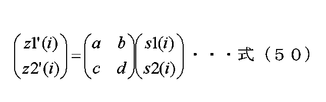
そして、位相変更部205Aは、重み付け合成後の信号204A、および、制御信号200を入力とし、制御信号200に基づき、重み付け合成後の信号204Aに対し、位相変更を施し、位相変更後の信号206Aを出力する。なお、位相変更後の信号206Aをz1(t)であらわし、z1(t)は複素数で定義し、実数であってもよい。
Then, the
位相変更部205Aの具体的動作について説明する。位相変更部205Aでは、例えば、z1’(i)に対しw(i)の位相変更を施す。したがって、z1(i)=w(i)×z1’(i)とあらわすことができる。iはシンボル番号であり、iは0以上の整数である。
The specific operation of the
例えば、位相変更の値を以下のように設定する。 For example, set the phase change value as follows.

Mは2以上の整数であり、Mは位相変更の周期となる。Mは3以上の奇数に設定するとデータの受信品質が向上する可能性がある。ただし、式(51)は、あくまでも例であり、これに限ったものではない。そこで、位相変更値w(i)=ej×λ(i)であらわす。 M is an integer of 2 or more, and M is the period of phase change. If M is set to an odd number of 3 or more, the data reception quality may improve. However, equation (51) is just an example and is not limited to this. Therefore, the phase change value w(i)=e j×λ(i) is expressed.
そして、位相変更部205Bは、重み付け合成後の信号204B、および、制御信号200を入力とし、制御信号200に基づき、重み付け合成後の信号204Bに対し、位相変更を施し、位相変更後の信号206Bを出力する。なお、位相変更後の信号206Bをz2(t)であらわし、z2(t)は複素数で定義し、実数であってもよい。
Then, the
位相変更部205Bの具体的動作について説明する。位相変更部205Bでは、例えば、z2’(i)に対しy(i)の位相変更を施す。したがって、z2(i)=y(i)×z2’(i)とあらわすことができる。iはシンボル番号であり、iは0以上の整数である。
The specific operation of the
例えば、位相変更の値を式(2)のように設定する。Nは2以上の整数であり、Nは位相変更の周期となる。N≠Mを満たす。Nは3以上の奇数に設定するとデータの受信品質が向上する可能性がある。ただし、式(2)は、あくまでも例であり、これに限ったものではない。そこで、位相変更値y(i)=ej×δ(i)であらわす。 For example, the phase change value is set as shown in equation (2). N is an integer of 2 or more, and N is the period of phase change. N≠M is satisfied. If N is set to an odd number of 3 or more, the data reception quality may improve. However, formula (2) is just an example, and is not limited to this. Therefore, the phase change value is expressed as y(i)=e j×δ(i) .
このときz1(i)およびz2(i)を以下の式であらわす。 At this time, z1(i) and z2(i) are expressed by the following equations.

なお、δ(i)、およびλ(i)は実数である。そして、z1(i)とz2(i)は、同一時間、同一周波数(同一周波数帯)で、送信装置から送信される。式(52)において、位相変更の値は、式(2)、式(52)に限ったものではなく、例えば、周期的、規則的に位相を変更するような方法が考えられる。 Note that δ(i) and λ(i) are real numbers. Then, z1(i) and z2(i) are transmitted from the transmitting device at the same time and at the same frequency (same frequency band). In Equation (52), the value of the phase change is not limited to Equation (2) and Equation (52); for example, a method of periodically and regularly changing the phase can be considered.
そして、実施の形態1で説明したように、式(50)および式(52)における(プリコーディング)行列としては、式(5)から式(36)までなどが考えられる。ただし、プリコーディング行列はこれらに限ったものではなく、実施の形態1についても同様である。
As described in
挿入部207Aは、重み付け合成後の信号204A、パイロットシンボル信号pa(t)251A、プリアンブル信号252、制御情報シンボル信号253、制御信号200を入力とし、制御信号200に含まれるフレーム構成の情報に基づき、フレーム構成に基づいたベースバンド信号208Aを出力する。tは時間を示す。
The
同様に、挿入部207Bは、位相変更後の信号206B、パイロットシンボル信号pb(t)251B、プリアンブル信号252、制御情報シンボル信号253、制御信号200を入力とし、制御信号200に含まれるフレーム構成の情報に基づき、フレーム構成に基づいたベースバンド信号208Bを出力する。
Similarly, the inserting
位相変更部209Bは、ベースバンド信号208B、および、制御信号200を入力とし、ベースバンド信号208Bに対し、制御信号200に基づいて、位相変更を行い、位相変更後の信号210Bを出力する。ベースバンド信号208Bをシンボル番号iの関数とし、x’(i)とあらわす。すると、位相変更後の信号x(i)210Bは、x(i)=ej×ε(i)×x’(i)とあらわすことができる。iは0以上の整数であり、jは虚数単位である。
The
なお、実施の形態1等で説明したように、位相変更部209Bの動作としては、非特許文献2、非特許文献3で記載されているCDD/CSDであってもよい。そして、位相変更部209Bは、周波数軸方向に存在するシンボルに対し、位相変更を行う。位相変更部209Bは、データシンボル、パイロットシンボル、制御情報シンボルなどに対し位相変更を施す。
Note that, as described in
図3は、図1の無線部107_A、107_Bの構成の一例であり、実施の形態1で詳細の説明を行ったので、説明は省略する。 FIG. 3 shows an example of the configuration of the wireless sections 107_A and 107_B in FIG. 1, and since the details have been explained in the first embodiment, the explanation will be omitted.
図4は、図1の送信信号108_Aのフレーム構成であり、実施の形態1で詳細の説明を行ったので、説明は省略する。 FIG. 4 shows the frame structure of the transmission signal 108_A in FIG. 1, and since the details were explained in the first embodiment, the explanation will be omitted.
図5は、図1の送信信号108_Bのフレーム構成であり、実施の形態1で詳細の説明を行ったので、説明は省略する。 FIG. 5 shows the frame structure of the transmission signal 108_B in FIG. 1, and since the details were explained in the first embodiment, the explanation will be omitted.
図4のキャリアA、時刻$Bにシンボルが存在し、図5のキャリアA、時刻$Bにシンボルが存在したとき、図4のキャリアA、時刻$Bのシンボルと図5のキャリアA、時刻$Bのシンボルは、同一時間、同一周波数に送信される。なお、フレーム構成については、図4、図5に限ったものではなく、あくまでも、図4、図5はフレーム構成の例である。 When a symbol exists at carrier A, time $B in FIG. 4, and a symbol exists at carrier A, time $B in FIG. 5, the symbol at carrier A, time $B in FIG. The $B symbols are transmitted at the same time and on the same frequency. Note that the frame configuration is not limited to those shown in FIGS. 4 and 5, and FIGS. 4 and 5 are merely examples of frame configurations.
そして、図4、図5におけるその他のシンボルは、「図2におけるプリアンブル信号252、制御情報シンボル信号253」に相当するシンボルであり、したがって、図4のその他のシンボル403と同一時刻、かつ、同一周波数(同一キャリア)の図5のその他のシンボル503は、制御情報を伝送している場合、同一のデータ(同一の制御情報)を伝送している。
The other symbols in FIGS. 4 and 5 are symbols corresponding to "the
なお、図4のフレームと図5のフレームを受信装置は同時に受信することを想定しているが、図4のフレーム、または、図5のフレームを受信しても受信装置は送信装置が送信したデータを得ることは可能である。 It is assumed that the receiving device receives the frame in FIG. 4 and the frame in FIG. 5 at the same time, but even if the receiving device receives the frame in FIG. 4 or the frame in FIG. It is possible to obtain data.
図6は、図2の制御情報信号253を生成するための制御情報生成に関する部分の構成の一例を示しており、実施の形態1で詳細の説明を行ったので、説明は省略する。 FIG. 6 shows an example of the configuration of a portion related to control information generation for generating the control information signal 253 of FIG. 2, and since the details were explained in the first embodiment, the explanation will be omitted.
図7は、図1のアンテナ部#A 109_A、アンテナ部#B 109_Bの構成の一例を示しており、アンテナ部#A 109_A、アンテナ部#B 109_Bが複数のアンテナで構成されている例である。図7は、実施の形態1で詳細の説明を行ったので、説明は省略する。
FIG. 7 shows an example of the configuration of antenna section #A 109_A and antenna section #B 109_B in FIG. 1, and is an example in which antenna section #A 109_A and antenna section #B 109_B are composed of a plurality of antennas. . Since the details of FIG. 7 were explained in
図8は、図1の送信装置が、例えば、図4、図5のフレーム構成の送信信号を送信したとき、その変調信号を受信する受信装置の構成の一例を示しており、実施の形態1で詳細の説明を行ったので、説明は省略する。 FIG. 8 shows an example of the configuration of a receiving device that receives a modulated signal when the transmitting device of FIG. 1 transmits a transmission signal having the frame structure of FIGS. 4 and 5, for example. Since the details have been explained in , the explanation will be omitted.
図10は、図8のアンテナ部#X 801X、アンテナ部#Y 801Yの構成の一例を示し、アンテナ部#X 801Xアンテナ部#Y 801Yが複数アンテナで構成されている例である。図10は、実施の形態1で詳細の説明を行ったので、説明は省略する。
FIG. 10 shows an example of the configuration of the antenna
次に、図1のように送信装置の信号処理部106が、図20に示すように、位相変更部205A、205Bと位相変更部209Aを挿入している。その特徴と、そのときの効果について説明する。
Next, as shown in FIG. 1, the
図4、図5を用いて説明したように、第1の系列を用いてマッピングすることによって得られたマッピング後の信号s1(i)201Aと第2の系列を用いてマッピングすることによって得られたマッピング後の信号s2(i)201Bに対し、プリコーディング(重み付け合成)を施し、得られた重み付け合成後の信号204A、204Bに対して、位相変更を行っているのが、位相変更部205A、205Bである。そして、位相変更後の信号206Aと位相変更後の信号206Bは、同一周波数、同一時間に送信される。したがって、図4、図5において、図4のデータシンボル402、図5のデータシンボル502に対して、位相変更を施す。iはシンボル番号であり、iは0以上の整数とする。
As explained using FIGS. 4 and 5, the mapped signal s1(i) 201A obtained by mapping using the first sequence and the mapped signal s1(i) 201A obtained by mapping using the second sequence The
例えば、図11は、図4のフレームに対し、キャリア1からキャリア5、時刻$4から時刻$6を抽出したものである。なお、図11は、図4と同様、パイロットシンボル401、データシンボル402、その他のシンボル403を示す。
For example, FIG. 11
上述のように、図11に示したシンボルにおいて、(キャリア1、時刻$5)、(キャリア2、時刻$5)、(キャリア3、時刻$5)、(キャリア4、時刻$5)、(キャリア5、時刻$5)、(キャリア1、時刻$6)、(キャリア2、時刻$6)、(キャリア4、時刻$6)、(キャリア5、時刻$6)におけるデータシンボルに対し、位相変更部205Aは位相変更を施す。
As mentioned above, in the symbols shown in FIG. 11, (
よって、図11に示したデータシンボルに対する位相変更値を、
(キャリア1、時刻$5)では「e j×λ15(i)」とし、
(キャリア2、時刻$5)では「e j×λ25(i)」とし、
(キャリア3、時刻$5)では「e j×λ35(i)」とし、
(キャリア4、時刻$5)では「e j×λ45(i)」とし、
(キャリア5、時刻$5)では「e j×λ55(i)」とし、
(キャリア1、時刻$6)では「e j×λ16(i)」とし、
(キャリア2、時刻$6)では「e j×λ26(i)」とし、
(キャリア4、時刻$6)では「e j×λ46(i)」とし、
(キャリア5、時刻$6)では「e j×λ56(i)」とする。
Therefore, the phase change value for the data symbol shown in FIG.
(
(
(
(
(
(
(
(
(
一方、図11に示したシンボルにおいて、(キャリア1、時刻$4)、(キャリア2、時刻$4)、(キャリア3、時刻$4)、(キャリア4、時刻$4)、及び、(キャリア5、時刻$4)におけるその他のシンボル、(キャリア3、時刻$6)におけるパイロットシンボルは、位相変更部205Aの位相変更の対象ではない。
On the other hand, in the symbols shown in FIG. 11, (
この点が位相変更部205Aの特徴的な点である。なお、図11における位相変更の対象である、(キャリア1、時刻$5)、(キャリア2、時刻$5)、(キャリア3、時刻$5)、(キャリア4、時刻$5)、(キャリア5、時刻$5)、(キャリア1、時刻$6)、(キャリア2、時刻$6)、(キャリア4、時刻$6)、及び、(キャリア5、時刻$6)におけるデータシンボルと「同一キャリア、同一時刻」には、図4に示したように、データキャリアが配置されている。
This point is a characteristic point of the
つまり、図4において、(キャリア1、時刻$5)、(キャリア2、時刻$5)、(キャリア3、時刻$5)、(キャリア4、時刻$5)、(キャリア5、時刻$5)、(キャリア1、時刻$6)、(キャリア2、時刻$6)、(キャリア4、時刻$6)、及び、(キャリア5、時刻$6)はデータシンボルである。
That is, in FIG. 4, (
つまり、MIMO伝送を行っている、又は、複数のストリームを伝送しているデータシンボルが位相変更部205Aの位相変更の対象である。
In other words, data symbols undergoing MIMO transmission or transmitting a plurality of streams are subject to phase change by the
なお、位相変更部205Aがデータシンボルに施す位相変更の例として、式(50)のように、データシンボルに、規則的な位相変更、つまり、周期Nの位相変更を行う方法がある。ただし、データシンボルに施す位相変更方法は、これに限ったものではない。
Note that as an example of the phase change that the
例えば、図11は、図5のフレームに対し、キャリア1からキャリア5、時刻$4から時刻$6を抽出したものである。なお、図11では、図5と同様、パイロットシンボル501、データシンボル502、その他のシンボル503を示す。
For example, FIG. 11
上述のように、図11に示したシンボルにおいて、(キャリア1、時刻$5)、(キャリア2、時刻$5)、(キャリア3、時刻$5)、(キャリア4、時刻$5)、(キャリア5、時刻$5)、(キャリア1、時刻$6)、(キャリア2、時刻$6)、(キャリア4、時刻$6)、及び、(キャリア5、時刻$6)におけるデータシンボルに対し、位相変更部205Bは位相変更を施す。
As mentioned above, in the symbols shown in FIG. 11, (
よって、図11に示したデータシンボルに対する位相変更値を、(キャリア1、時刻$5)では「ej×δ15(i)」とし、(キャリア2、時刻$5)では「ej×δ25(i)」とし、(キャリア3、時刻$5)では「ej×δ35(i)」とし、(キャリア4、時刻$5)では「ej×δ45(i)」とし、(キャリア5、時刻$5)では「ej×δ55(i)」とし、(キャリア1、時刻$6)では「ej×δ16(i)」とし、(キャリア2、時刻$6)では「ej×δ26(i)」とし、(キャリア4、時刻$6)では「ej×δ46(i)」とし、(キャリア5、時刻$6)では「ej×δ56(i)」とする。
Therefore, the phase change value for the data symbol shown in FIG. 11 is set to "e j × δ15(i) " at (
一方、図11に示したシンボルにおいて、(キャリア1、時刻$4)、(キャリア2、時刻$4)、(キャリア3、時刻$4)、(キャリア4、時刻$4)、及び、キャリア5、時刻$4)におけるその他のシンボル、(キャリア3、時刻$6)におけるパイロットシンボルは、位相変更部205Bの位相変更の対象ではない。
On the other hand, in the symbols shown in FIG. 11, (
この点が位相変更部205Bの特徴的な点である。なお、図11における位相変更の対象である、(キャリア1、時刻$5)、(キャリア2、時刻$5)、(キャリア3、時刻$5)、(キャリア4、時刻$5)、(キャリア5、時刻$5)、(キャリア1、時刻$6)、(キャリア2、時刻$6)、(キャリア4、時刻$6)、及び、(キャリア5、時刻$6)におけるデータシンボルと「同一キャリア、同一時刻」には、図4に示したように、データキャリアが配置されている。
This point is a characteristic point of the
つまり、図4において、(キャリア1、時刻$5)、(キャリア2、時刻$5)、(キャリア3、時刻$5)、(キャリア4、時刻$5)、(キャリア5、時刻$5)、(キャリア1、時刻$6)、(キャリア2、時刻$6)、(キャリア4、時刻$6)、及び、(キャリア5、時刻$6)はデータシンボルである。
That is, in FIG. 4, (
つまり、MIMO伝送を行っている、又は、複数のストリームを伝送しているデータシンボルが位相変更部205Bの位相変更の対象である。
In other words, data symbols undergoing MIMO transmission or transmitting a plurality of streams are subject to phase change by the
なお、位相変更部205Bがデータシンボルに施す位相変更の例として、式(2)のように、データシンボルに、規則的な位相変更、つまり、周期Nの位相変更を行う方法がある。ただし、データシンボルに施す位相変更方法は、これに限ったものではない。
Note that as an example of the phase change that the
このようにすることで、直接波が支配的な環境、例えば、LOS環境のときに、MIMO伝送を行っている、又は、複数のストリームを伝送しているデータシンボルの受信装置におけるデータの受信品質が向上するという効果を得ることができる。この効果について、説明を行う。 By doing this, in an environment where direct waves are dominant, for example, a LOS environment, the data reception quality in a data symbol receiving device that is performing MIMO transmission or transmitting multiple streams can be improved. It is possible to obtain the effect of improving. This effect will be explained.
例えば、図1のマッピング部104で使用する変調方式がQPSKである。図18のマッピング後の信号201AはQPSKの信号であり、また、マッピング後の信号201BもQPSKの信号となる。つまり、2つのQPSKのストリームを送信する。
For example, the modulation method used by
すると、図8の信号処理部811では、例えば、チャネル推定信号806_1、806_2を用いて、16個の候補信号点を得る。QPSKは2ビットを伝送でき、2ストリームにより、計4ビットを伝送する。よって、24=16個の候補信号点が存在する。
Then, the
なお、チャネル推定信号808_1、808_2を用いて、別の16個の候補信号点を得ることにもなるが、説明は同様となるため、チャネル推定信号806_1、806_2を用いて得られる16個の候補信号点について、焦点をあて、説明を進める。 Note that another 16 candidate signal points are obtained using the channel estimation signals 808_1 and 808_2, but the explanation is the same, so the 16 candidates obtained using the channel estimation signals 806_1 and 806_2 Let's focus on the signal points and proceed with the explanation.
このときの状態の一例を図12に示す。図12A、図12B、いずれも横軸は同相I、縦軸は直交Qであり、同相I-直交Q平面において、16個の候補信号点が存在する。16個の候補信号点のうち、一つが、送信装置が送信した信号点である。このため、「16個の候補信号点」と呼ぶ。 An example of the state at this time is shown in FIG. In both FIGS. 12A and 12B, the horizontal axis is in-phase I, and the vertical axis is quadrature Q, and there are 16 candidate signal points in the in-phase I-quadrature Q plane. One of the 16 candidate signal points is a signal point transmitted by the transmitting device. Therefore, they are called "16 candidate signal points."
直接波が支配的な環境、例えば、LOS環境のとき、第1のケースとして、「図20の位相変更部205A、205Bが存在しない場合、つまり、図20の位相変更部205A、205Bによる位相変更を行わない場合」を考える。
In an environment where direct waves are dominant, for example, a LOS environment, the first case is ``If the
「第1のケース」の場合、位相変更が行われないため、図12Aのような状態に陥る可能性がある。図12Aの状態に陥った場合、「信号点1201、1202」、「信号点1203、1204、1205、1206」、「信号点1207、1208」のように、信号点が密の部分が存在するため、図8の受信装置において、データの受信品質が低下する可能性がある。 In the "first case", no phase change is performed, so there is a possibility of falling into a state as shown in FIG. 12A. In the case of the state shown in FIG. 12A, there are parts with dense signal points, such as "signal points 1201, 1202," "signal points 1203, 1204, 1205, 1206," and "signal points 1207, 1208." , in the receiving apparatus shown in FIG. 8, there is a possibility that the data reception quality will be degraded.
この現象を克服するために、図20において、位相変更部205A、205Bを挿入している。位相変更部205A、205Bを挿入すると、シンボル番号iにより、図12Aに示す「信号点が密の部分」が存在するシンボル番号と、図12Bに示す「信号点間の距離が長い」というシンボル番号とが混在する。この状態に対し、誤り訂正符号を導入しているため、高い誤り訂正能力を得ることができ、図8の受信装置において、高いデータ受信品質を得ることができる。
In order to overcome this phenomenon,
なお、図20において、パイロットシンボル、プリアンブルなど、データシンボルを復調(検波)するための、チャネル推定を行うための「パイロットシンボル、プリアンブル」に対し、図20の位相変更部205A、205Bにおいて、位相変更を行わない。これにより、データシンボルにおいて、「シンボル番号iにより、図12Aに示す「信号点が密の部分」が存在するシンボル番号と、図12Bに示す「信号点間の距離が長い」というシンボル番号とが混在すること」を実現することができる。
Note that in FIG. 20, the
ただし、パイロットシンボル、プリアンブルなど、データシンボルを復調(検波)するための、チャネル推定を行うための「パイロットシンボル、プリアンブル」に対し、図20の位相変更部205A、205Bにおいて、位相変更を行っても、「データシンボルにおいて、「シンボル番号iにより、図12Aに示す信号点が密の部分が存在するシンボル番号と、図12Bに示す「信号点間の距離が長い」というシンボル番号とが混在すること」を実現することができる」場合がある。
However, the
この場合、パイロットシンボル、プリアンブルに対し、何らかの条件を付加して、位相変更を行わなければならない。例えば、データシンボルに対する位相変更の規則とは別の規則を設けて、「パイロットシンボル、および/または、プリアンブルに対し位相変更を施す」という方法が考えられる。例として、データシンボルに対し規則的に周期Nの位相変更を施し、パイロットシンボル、および/または、プリアンブルに対し規則的に周期Mの位相変更を施す、という方法がある。N、Mは2以上の整数となる。 In this case, it is necessary to add some conditions to the pilot symbols and preamble to change the phase. For example, a method can be considered in which a rule different from the phase change rule for data symbols is provided, and the phase is changed for pilot symbols and/or preambles. As an example, there is a method in which data symbols are regularly subjected to a phase change with a period of N, and pilot symbols and/or preambles are regularly subjected to a phase change with a period of M. N and M are integers of 2 or more.
前述より、位相変更部209Bは、ベースバンド信号208B、および、制御信号200を入力とし、ベースバンド信号208Bに対し、制御信号200に基づいて、位相変更を行い、位相変更後の信号210Bを出力する。ベースバンド信号208Bをシンボル番号iの関数とし、x’(i)とあらわす。すると、位相変更後の信号210B(x(i))は、x(i)=ej×ε(i)×x’(i)とあらわすことができる。iは0以上の整数であり、jは虚数単位である。
As described above, the
そして、位相変更部209Bの動作としては、非特許文献2、非特許文献3で記載されているCDD/CSDであってもよい。そして、位相変更部209Bは、周波数軸方向に存在するシンボルに対し、位相変更を行う点である。位相変更部209Bは、データシンボル、パイロットシンボル、制御情報シンボルなどに対し位相変更を施す。したがって、このケースの場合、シンボル番号iの対象となるシンボルは、データシンボル、パイロットシンボル、制御情報シンボル、プリアンブル(その他のシンボル)などとなる。
The operation of the
図20の場合、位相変更部209Bは、ベースバンド信号208Bに対して位相変更を施しているため、図5に記載されている各シンボルに対して位相変更を施す。
In the case of FIG. 20, the
したがって、図5のフレームにおいて、時刻$1の全てのキャリアの全てのシンボル(その他のシンボル503)に対し、図20の位相変更部209Bは、位相変更を施す。
Therefore, in the frame of FIG. 5, the
同様に、図20の位相変更部209Bは、下記のシンボルに対して、位相変更を施す。
「時刻$2の全てのキャリアの全てのシンボル(その他のシンボル503)」、
「時刻$3の全てのキャリアの全てのシンボル(その他のシンボル503)」、
「時刻$4の全てのキャリアの全てのシンボル(その他のシンボル503)」、
「時刻$5の全てのキャリアの全てのシンボル(パイロットシンボル501、または、データシンボル502)」、
「時刻$6の全てのキャリアの全てのシンボル(パイロットシンボル501、または、データシンボル502)」、
「時刻$7の全てのキャリアの全てのシンボル(パイロットシンボル501、または、データシンボル502)」、
「時刻$8の全てのキャリアの全てのシンボル(パイロットシンボル501、または、データシンボル502)」、
「時刻$9の全てのキャリアの全てのシンボル(パイロットシンボル501、または、データシンボル502)」、
「時刻$10の全てのキャリアの全てのシンボル(パイロットシンボル501、または、データシンボル502)」、
「時刻$11の全てのキャリアの全てのシンボル(パイロットシンボル501、または、データシンボル502)」、上記以外の時刻、キャリアの記載は省略する。
Similarly, the
"All symbols of all carriers at time $2 (other symbols 503)",
"All symbols of all carriers at time $3 (other symbols 503)",
"All symbols of all carriers at time $4 (other symbols 503)",
"All symbols of all carriers at time $5 (pilot symbol 501 or data symbol 502)",
"All symbols of all carriers at time $6 (pilot symbol 501 or data symbol 502)",
"All symbols of all carriers at time $7 (pilot symbol 501 or data symbol 502)",
"All symbols of all carriers at time $8 (pilot symbol 501 or data symbol 502)",
"All symbols of all carriers at time $9 (pilot symbol 501 or data symbol 502)",
"All symbols of all carriers at time $10 (pilot symbol 501 or data symbol 502)",
"All symbols of all carriers at time $11 (pilot symbol 501 or data symbol 502)" and other times and carriers are omitted.
図13は、図1の送信信号108_Aの図4とは異なるフレーム構成であり、実施の形態1において、詳細の説明を行ったので、説明を省略する。
FIG. 13 shows a frame structure of the transmission signal 108_A in FIG. 1 that is different from that in FIG. 4, and since the detailed explanation was given in
図14は、図1の送信信号108_Bの図5とは異なるフレーム構成であり、実施の形態1において、詳細の説明を行ったので、説明を省略する。 FIG. 14 shows a frame structure of the transmission signal 108_B in FIG. 1 that is different from that in FIG. 5, and since the detailed explanation was given in the first embodiment, the explanation will be omitted.
図13のキャリアA、時刻$Bにシンボルが存在し、図14のキャリアA、時刻$Bにシンボルが存在したとき、図13のキャリアA、時刻$Bのシンボルと図14のキャリアA、時刻$Bのシンボルは、同一時間、同一周波数に送信される。なお、図13、図14のフレーム構成は、あくまでも例である。 When a symbol exists at carrier A, time $B in FIG. 13, and a symbol exists at carrier A, time $B in FIG. 14, the symbol at carrier A, time $B in FIG. The $B symbols are transmitted at the same time and on the same frequency. Note that the frame configurations in FIGS. 13 and 14 are merely examples.
そして、図13、図14におけるその他のシンボルは、「図20におけるプリアンブル信号252、制御情報シンボル信号253」に相当するシンボルであり、したがって、図13のその他のシンボル403と同一時刻、かつ、同一周波数(同一キャリア)の図14のその他のシンボル503は、制御情報を伝送している場合、同一のデータ(同一の制御情報)を伝送している。
The other symbols in FIGS. 13 and 14 are symbols corresponding to "the
なお、図13のフレームと図14のフレームを受信装置は同時に受信することを想定しているが、図13のフレーム、または、図14のフレームを受信しても受信装置は送信装置が送信したデータを得ることは可能である。 Note that although it is assumed that the receiving device receives the frame in FIG. 13 and the frame in FIG. 14 at the same time, even if the receiving device receives the frame in FIG. 13 or the frame in FIG. It is possible to obtain data.
位相変更部209Bは、ベースバンド信号208B、および、制御信号200を入力とし、ベースバンド信号208Bに対し、制御信号200に基づいて、位相変更を行い、位相変更後の信号210Bを出力する。ベースバンド信号208Bをシンボルシンボル番号iの関数とし、x’(i)とあらわす。
The
すると、位相変更後の信号210B(x(i))は、x(i)=e j×ε(i)×x’(i)とあらわすことができる。iは0以上の整数であり、jは虚数単位である。そして、位相変更部209Bの動作としては、非特許文献2、非特許文献3で記載されているCDD/CSDであってもよい。
Then, the phase-changed
そして、位相変更部209Bは、周波数軸方向に存在するシンボルに対し、位相変更を行う点である。位相変更部209Bは、データシンボル、パイロットシンボル、制御情報シンボルなどに対し位相変更を施す。このとき、ヌルシンボルも位相変更の対象と考えることができる。したがって、このケースの場合、シンボル番号iの対象となるシンボルは、データシンボル、パイロットシンボル、制御情報シンボル、プリアンブル(その他のシンボル)、ヌルシンボルなどとなる。
The
しかし、ヌルシンボルは、同相成分Iがゼロ(0)、かつ、直交成分Qがゼロ(0)であるため、ヌルシンボルに対し位相変更を行っても位相変更前の信号と位相変更後の信号は同じである。したがって、ヌルシンボルは位相変更の対象でないと解釈することも可能である。図20の場合、位相変更部209Bは、ベースバンド信号208Bに対して位相変更を施しているため、図14に記載されている各シンボルに対して位相変更を施す。
However, since the null symbol has an in-phase component I of zero (0) and a quadrature component Q of zero (0), even if the phase of the null symbol is changed, the signal before the phase change and the signal after the phase change are the same. Therefore, it is also possible to interpret the null symbol as not being subject to phase change. In the case of FIG. 20, the
したがって、図14のフレームにおいて、時刻$1の全てのキャリアの全てのシンボル(その他のシンボル503)に対し、図20の位相変更部209Bは、位相変更を施す。ただし、ヌルシンボル1301の位相変更の扱いについては前に説明したとおりである。
Therefore, in the frame of FIG. 14, the
同様に、図20の位相変更部209Bは、下記のシンボルに対して、位相変更を施す
「時刻$2の全てのキャリアの全てのシンボル(その他のシンボル503)」、
「時刻$3の全てのキャリアの全てのシンボル(その他のシンボル503)」、
「時刻$4の全てのキャリアの全てのシンボル(その他のシンボル503)」、
「時刻$5の全てのキャリアの全てのシンボル(パイロットシンボル501、または、データシンボル502)」、
「時刻$6の全てのキャリアの全てのシンボル(パイロットシンボル501、または、データシンボル502)」、
「時刻$7の全てのキャリアの全てのシンボル(パイロットシンボル501、または、データシンボル502)」、
「時刻$8の全てのキャリアの全てのシンボル(パイロットシンボル501、または、データシンボル502)」、
「時刻$9の全てのキャリアの全てのシンボル(パイロットシンボル501、または、データシンボル502)」、
「時刻$10の全てのキャリアの全てのシンボル(パイロットシンボル501、または、データシンボル502)」、
「時刻$11の全てのキャリアの全てのシンボルに対し(パイロットシンボル501、または、データシンボル502)」、ただし、全ての時刻、全てキャリアにおいて、ヌルシンボル1301の位相変更の扱いについては前に説明したとおりである。上記以外の時刻、キャリアについての記載を省略する。
Similarly, the
"All symbols of all carriers at time $3 (other symbols 503)",
"All symbols of all carriers at time $4 (other symbols 503)",
"All symbols of all carriers at time $5 (pilot symbol 501 or data symbol 502)",
"All symbols of all carriers at time $6 (pilot symbol 501 or data symbol 502)",
"All symbols of all carriers at time $7 (pilot symbol 501 or data symbol 502)",
"All symbols of all carriers at time $8 (pilot symbol 501 or data symbol 502)",
"All symbols of all carriers at time $9 (pilot symbol 501 or data symbol 502)",
"All symbols of all carriers at time $10 (pilot symbol 501 or data symbol 502)",
"For all symbols of all carriers at time $11 (pilot symbol 501 or data symbol 502)" However, the handling of the phase change of null symbol 1301 at all times and all carriers was explained earlier. As I said. Descriptions of times and carriers other than those listed above will be omitted.
位相変更部209Bにおける位相変更値をΩ(i)とあらわす。ベースバンド信号208Bはx’(i)であり、位相変更後の信号210Bはx(i)である。したがって、x(i)=Ω(i)×x’(i)が成立する。
The phase change value in the
例えば、位相変更の値を式(38)と設定する。Qは2以上の整数であり、Qは位相変更の周期となる。jは虚数単位である。ただし、式(38)は、あくまでも例であり、これに限ったものではない。 For example, the value of phase change is set as equation (38). Q is an integer of 2 or more, and Q is the period of phase change. j is an imaginary unit. However, equation (38) is just an example and is not limited to this.
例えば、周期Qを持つように位相変更を行うようにΩ(i)を設定してもよい。 For example, Ω(i) may be set to change the phase so that it has a period Q.
また、例えば、図5、図14において、同一キャリアに対して、同一の位相変更値を与え、キャリアごとに位相変更値を設定するとしてもよい。例えば、以下のようになる。
・図5、図14におけるキャリア1に対し、時刻によらず、位相変更値を式(39)とする。
・図5、図14におけるキャリア2に対し、時刻によらず、位相変更値を式(40)とする。
・図5、図14におけるキャリア3に対し、時刻によらず、位相変更値を式(41)とする。
・図5、図14におけるキャリア4に対し、時刻によらず、位相変更値を式(42)とする。以後のキャリアについては記載を省略する。
Furthermore, for example, in FIGS. 5 and 14, the same phase change value may be given to the same carrier, and the phase change value may be set for each carrier. For example, as follows.
- For
- For
- For
- For
以上が、図20の位相変更部209Bの動作例となる。
The above is an example of the operation of the
図20の位相変更部209Bにより得られる効果について説明する。
The effects obtained by the
「図4および図5のフレーム」、または、「図13および図14のフレーム」のその他のシンボル403、503には、制御情報シンボルが含まれている。前述より、その他のシンボル403と同一時刻、かつ、同一の周波数(同一のキャリア)の図5のその他のシンボル503は、制御情報を伝送している場合、同一データ(同一の制御情報)を送信している。 Other symbols 403 and 503 of the "frames in FIGS. 4 and 5" or the "frames in FIGS. 13 and 14" include control information symbols. As mentioned above, if the other symbol 503 in FIG. 5 at the same time and the same frequency (same carrier) as the other symbol 403 is transmitting control information, it transmits the same data (same control information). are doing.
ところで、ケース2:「制御情報シンボルを、図1のアンテナ部#A 109_A、または、アンテナ部#B 109_Bのいずれか一方のアンテナ部を用いて送信する。」を考える。 By the way, consider Case 2: "The control information symbol is transmitted using either the antenna section #A 109_A or the antenna section #B 109_B in FIG. 1."
「ケース2」のように送信した場合、制御情報シンボルを送信するアンテナ数が1のため、「アンテナ部#A 109_Aとアンテナ部#B 109_Bの両者を用いて制御情報シンボルを送信する」場合と比較して、空間ダイバーシチのゲインが小さくなるため、「ケース2」の際、図8の受信装置で受信してもデータの受信品質が低下する。したがって、データの受信品質の向上という点では、「アンテナ部#A 109_Aとアンテナ部#B 109_Bの両者を用いて制御情報シンボルを送信する」ほうがよい。
When transmitting as in "
ケース3:「制御情報シンボルを、図1のアンテナ部#A 109_Aとアンテナ部#B 109_Bの両者を用いて送信する。ただし、図20における位相変更部209Bで位相変更を行わない。」を考える。
Case 3: Consider "The control information symbol is transmitted using both the antenna unit #A 109_A and the antenna unit #B 109_B in FIG. 1. However, the phase is not changed by the
「ケース3」のように送信した場合、アンテナ部#A109_Aから送信した変調信号とアンテナ部#B109_Bから送信した変調信号が同一である、または、特定の位相のずれがあるため、電波の伝搬環境によっては、図8の受信装置は、劣悪な受信信号になる可能性があり、両者の変調信号が同一のマルチパスの影響を受ける可能性がある。これにより、図8の受信装置において、データの受信品質が低下するという現象がある。
When transmitting as in "
この現象を軽減するために、図20において、位相変更部209Bを設けている。これにより、時間、または、周波数方向で、位相を変更しているため、図8の受信装置において、劣悪な受信信号となる可能性を低減することができる。また、アンテナ部#A109_Aから送信した変調信号が受けるマルチパスの影響とアンテナ部#B109_Bから送信した変調信号が受けるマルチパスの影響に違いがある可能性が高いため、ダイバーシチゲインが得られる可能性が高く、これにより、図8の受信装置において、データの受信品質が向上する。
In order to alleviate this phenomenon, a
以上の理由から、図20において、位相変更部209Bを設け、位相変更を施している。
For the above reasons, in FIG. 20, a
その他のシンボル403、および、その他のシンボル503には、制御情報シンボル以外に、例えば、信号検出のためシンボル、周波数同期及び時間同期を行うためのシンボル、チャネル推定のためのシンボルが、制御情報シンボルを復調及び復号するために含まれいてる。また、「図4および図5のフレーム」、または、「図13および図14のフレーム」には、パイロットシンボル401、501が含まれており、これらを用いることで、制御情報シンボルをより高精度に復調及び復号を行うことが可能となる。 Other symbols 403 and other symbols 503 include, in addition to control information symbols, symbols for signal detection, symbols for frequency synchronization and time synchronization, symbols for channel estimation, and control information symbols. included for demodulating and decoding. In addition, the "frames in FIGS. 4 and 5" or "frames in FIGS. 13 and 14" include pilot symbols 401 and 501, and by using these, control information symbols can be converted with higher accuracy. It becomes possible to perform demodulation and decoding.
そして、「図4および図5のフレーム」、または、「図13および図14のフレーム」には、データシンボル402、および、データシンボル502により、同一周波数(周波数帯)、同一時間を用いて、複数のストリームを伝送している、又は、MIMO伝送を行っている。 The "frames in FIGS. 4 and 5" or the "frames in FIGS. 13 and 14" use the same frequency (frequency band) and the same time using the data symbol 402 and the data symbol 502. Multiple streams are being transmitted or MIMO transmission is being performed.
これらのデータシンボルを復調するためには、その他のシンボル403、および、その他のシンボル503に含まれている、信号検出のためのシンボル、周波数同期及び時間同期を行うためのシンボル、チャネル推定のためのシンボルを用いる。 In order to demodulate these data symbols, other symbols 403 and 503 include symbols for signal detection, symbols for frequency synchronization and time synchronization, and symbols for channel estimation. Use the symbol.
このとき、「その他のシンボル403、および、その他のシンボル503に含まれている、信号検出のためのシンボル、周波数同期及び時間同期を行うためのシンボル、チャネル推定のためのシンボル」は、前述より、位相変更部209Bにより、位相変更を行っている。
At this time, "symbols for signal detection, symbols for performing frequency synchronization and time synchronization, and symbols for channel estimation included in other symbols 403 and other symbols 503" are as follows from the above. , the phase is changed by the
そのような状況の中、「データシンボル402、および、データシンボル502に対し」又は「上述の説明の場合は、データシンボル502に対し」、この処理を反映させなかった場合、受信装置において、データシンボル402、および、データシンボル502を復調及び復号する場合、位相変更部209Bで行った位相変更に対する処理を反映させた復調及び復号を行う必要があり、その処理は複雑となる可能性が高い。
In such a situation, if this processing is not reflected "for the data symbol 402 and the data symbol 502" or "for the data symbol 502 in the case of the above explanation", the receiving device When demodulating and decoding symbols 402 and data symbols 502, it is necessary to perform demodulation and decoding that reflect the processing for the phase change performed by
「その他のシンボル403、および、その他のシンボル503に含まれている、信号検出のためのシンボル、周波数同期及び時間同期を行うためのシンボル、チャネル推定のためのシンボル」は、位相変更部209Bにより、位相変更を行っているためである。
“Symbols for signal detection, symbols for performing frequency synchronization and time synchronization, and symbols for channel estimation included in other symbols 403 and other symbols 503” are processed by the
しかし、図20に示すように、位相変更部209Bにおいて、「データシンボル402、および、データシンボル502に対し」、または「上述の説明の場合は、データシンボル502に対し」、位相変更を施した場合、受信装置において、「その他のシンボル403、および、その他のシンボル503に含まれている、信号検出のためのシンボル、周波数同期及び時間同期を行うためのシンボル、チャネル推定のためのシンボル」を用いて推定した、チャネル推定信号(伝搬路変動の推定信号)を用いて、簡単にデータシンボル402、および、データシンボル502を復調及び復号を行うことができるという利点がある。
However, as shown in FIG. 20, in the
加えて、図20に示すように、位相変更部209Bにおいて、「データシンボル402、および、データシンボル502に対し」、または、「上述の説明の場合は、データシンボル502に対し」、位相変更を施した場合、マルチパスにおける、周波数軸における、電界強度の急激な落ち込みの影響を少なくすることができ、これにより、データシンボル402、および、データシンボル502のデータの受信品質が向上するという効果を得ることができる可能性がある。
In addition, as shown in FIG. 20, the
このように、「位相変更部205A、205Bの位相変更を施すシンボルの対象」と「位相変更部209Bの位相変更を施すシンボルの対象」が異なる点が特徴的な点となる。
In this way, the characteristic point is that "the symbols whose phases are changed by the
以上のように、図20の位相変更部205A、205Bにより位相変更を行うことで、データシンボル402、および、データシンボル502の、例えば、LOS環境において、受信装置におけるデータの受信品質が向上するという効果を得ることができ、図20の位相変更部209Bにより位相変更を行うことで、例えば、「図4および図5のフレーム」、または、「図13および図14のフレーム」に含まれる制御情報シンボルの、受信装置における受信品質が向上し、データシンボル402、および、データシンボル502の復調及び復号の動作が簡単になるという効果を得ることができる。
As described above, by changing the phase by the
なお、図20の位相変更部205A、205Bにより位相変更を行うことで、データシンボル402、および、データシンボル502の、例えば、LOS環境において、受信装置におけるデータの受信品質が向上するという効果を得ることができ、さらに、データシンボル402、および、データシンボル502に対して、図20の位相変更部209Bにより位相変更を行うことで、データシンボル402、および、データシンボル502の受信品質が向上する。
Note that by changing the phase by the
なお、式(38)におけるQは―2以下の整数であってもよく、このとき、位相変更の周期は、Qの絶対値となる。この点については、実施の形態1にも適用することができる。 Note that Q in equation (38) may be an integer less than or equal to -2, and in this case, the period of phase change is the absolute value of Q. This point can also be applied to the first embodiment.
(実施の形態5)
本実施の形態では、実施の形態1における図2とは異なる構成の実施方法について説明する。
(Embodiment 5)
In this embodiment, a method of implementing a configuration different from that in FIG. 2 in
図1は、本実施の形態における例えば、基地局、アクセスポイント、放送局等の送信装置の構成の一例であり、詳細については、実施の形態1で説明したので、説明は省略する。
FIG. 1 shows an example of the configuration of a transmitting device such as a base station, an access point, a broadcast station, etc. in this embodiment, and since the details have been explained in
信号処理部106は、マッピング後の信号105_1、105_2、信号群110、制御信号100を入力とし、制御信号100に基づいて、信号処理を行い、信号処理後の信号106_A、106_Bを出力する。このとき、信号処理後の信号106_Aをu1(i)、信号処理後の信号106_Bをu2(i)とあらわす。iはシンボル番号であり、例えば、iは0以上の整数とする。なお、信号処理の詳細については、図21を用いて説明する。
The
図21は、図1における信号処理部106の構成の一例を示している。重み付け合成部(プリコーディング部)203は、マッピング後の信号201A(図1のマッピング後の信号105_1)、および、マッピング後の信号201B(図1のマッピング後の信号105_2)、および、制御信号200(図1の制御信号100)を入力とし、制御信号200に基づき重み付け合成(プリコーディング)を行い、重み付け後の信号204Aおよび重み付け後の信号204Bを出力する。
FIG. 21 shows an example of the configuration of the
このとき、マッピング後の信号201Aをs1(t)、マッピング後の信号201Bをs2(t)、重み付け後の信号204Aをz1’(t)、重み付け後の信号204Bをz2’(t)とあらわす。なお、tは一例として、時間とする。s1(t)、s2(t)、z1’(t)、z2’(t)は複素数で定義され、したがって、実数であってもよい。
At this time, the
ここでは、時間の関数として扱っているが「周波数(キャリア番号)」の関数としてもよいし、「時間及び周波数」の関数としてもよい。また、「シンボル番号」の関数としてもよい。この点は、実施の形態1でも同様である。 Here, it is treated as a function of time, but it may also be a function of "frequency (carrier number)" or a function of "time and frequency." Alternatively, it may be a function of "symbol number". This point also applies to the first embodiment.
重み付け合成部(プリコーディング部)203は、式(49)の演算を行う。 The weighted synthesis unit (precoding unit) 203 performs the calculation of equation (49).
そして、位相変更部205Aは、重み付け合成後の信号204A、および、制御信号200を入力とし、制御信号200に基づき、重み付け合成後の信号204Aに対し、位相変更を施し、位相変更後の信号206Aを出力する。なお、位相変更後の信号206Aをz1(t)であらわし、z1(t)は複素数で定義され、実数であってもよい。
Then, the
位相変更部205Aの具体的動作について説明する。位相変更部205Aでは、例えば、z1’(i)に対しw(i)の位相変更を施す。したがって、z1(i)=w(i)×z1’(i)とあらわすことができる。iはシンボル番号であり、iは0以上の整数とする。
The specific operation of the
例えば、位相変更の値を式(50)のように設定する。 For example, the phase change value is set as shown in equation (50).
Mは2以上の整数であり、Mは位相変更の周期となる。また、Mは3以上の奇数に設定するとデータの受信品質が向上する可能性がある。ただし、式(50)は、あくまでも例であり、これに限ったものではない。そこで、位相変更値w(i)=ej×λ(i)であらわす。 M is an integer of 2 or more, and M is the period of phase change. Further, if M is set to an odd number of 3 or more, the data reception quality may be improved. However, equation (50) is just an example and is not limited to this. Therefore, the phase change value w(i)=e j×λ(i) is expressed.
そして、位相変更部205Bは、重み付け合成後の信号204B、および、制御信号200を入力とし、制御信号200に基づき、重み付け合成後の信号204Bに対し、位相変更を施し、位相変更後の信号206Bを出力する。なお、位相変更後の信号206Bをz2(t)であらわし、z2(t)は複素数で定義され、実数であってもよい。
Then, the
位相変更部205Bの具体的動作について説明する。位相変更部205Bでは、例えば、z2’(i)に対しy(i)の位相変更を施す。したがって、z2(i)=y(i)×z2’(i)とあらわすことができる。iはシンボル番号であり、iは0以上の整数とする。
The specific operation of the
例えば、位相変更の値を式(2)のように設定する。Nは2以上の整数であり、Nは位相変更の周期となる。N≠Mを満たす。Nは3以上の奇数に設定するとデータの受信品質が向上する可能性がある。ただし、式(2)は、あくまでも例であり、これに限ったものではない。そこで、位相変更値y(i)=ej×δ(i)であらわす。 For example, the phase change value is set as shown in equation (2). N is an integer of 2 or more, and N is the period of phase change. N≠M is satisfied. If N is set to an odd number of 3 or more, the data reception quality may improve. However, formula (2) is just an example, and is not limited to this. Therefore, the phase change value is expressed as y(i)=e j×δ(i) .
このときz1(i)およびz2(i)は式(51)であらわすことができる。 At this time, z1(i) and z2(i) can be expressed by equation (51).
なお、δ(i)、およびλ(i)は実数である。そして、z1(i)とz2(i)は、同一時間、同一周波数(同一周波数帯)で、送信装置から送信される。式(51)において、位相変更の値は、式(2)、式(51)に限ったものではなく、例えば、周期的、規則的に位相を変更するような方法が考えられる。 Note that δ(i) and λ(i) are real numbers. Then, z1(i) and z2(i) are transmitted from the transmitting device at the same time and at the same frequency (same frequency band). In Equation (51), the value of the phase change is not limited to Equation (2) and Equation (51); for example, a method of periodically and regularly changing the phase can be considered.
そして、実施の形態1で説明したように、式(49)および式(51)における行列(プリコーディング行列)としては、式(5)から式(36)までなどが考えられる。ただし、プリコーディング行列はこれらに限ったものではなく、実施の形態1についても同様である。
As described in
挿入部207Aは、重み付け合成後の信号204A、パイロットシンボル信号pa(t)251A、プリアンブル信号252、制御情報シンボル信号253、制御信号200を入力とし、制御信号200に含まれるフレーム構成の情報に基づき、フレーム構成に基づいたベースバンド信号208Aを出力する。tは、時間を示す。
The
同様に、挿入部207Bは、位相変更後の信号206B、パイロットシンボル信号pb(t)251B、プリアンブル信号252、制御情報シンボル信号253、制御信号200を入力とし、制御信号200に含まれるフレーム構成の情報に基づき、フレーム構成に基づいたベースバンド信号208Bを出力する。
Similarly, the inserting
位相変更部209Bは、ベースバンド信号208B、および、制御信号200を入力とし、ベースバンド信号208Bに対し、制御信号200に基づいて、位相変更を行い、位相変更後の信号210Bを出力する。ベースバンド信号208Bをシンボル番号iの関数とし、x’(i)とあらわす。すると、位相変更後の信号x(i)210Bは、x(i)=ej×ε(i)×x’(i)とあらわすことができる。iは0以上の整数であり、jは虚数単位である。
The
なお、実施の形態1等で説明したように、位相変更部209Bの動作としては、非特許文献2、非特許文献3で記載されているCDD/CSDであってもよい。そして、位相変更部209Bは、周波数軸方向に存在するシンボルに対し、位相変更を行う。位相変更部209Bは、データシンボル、パイロットシンボル、制御情報シンボルなどに対し位相変更を施す。
Note that, as described in
図3は、図1の無線部107_A、107_Bの構成の一例であり、図4は、図1の送信信号108_Aのフレーム構成であり、図5は、図1の送信信号108_Bのフレーム構成であり、実施の形態1で詳細の説明を行ったので、説明は省略する。
3 shows an example of the configuration of the wireless sections 107_A and 107_B in FIG. 1, FIG. 4 shows the frame structure of the transmission signal 108_A in FIG. 1, and FIG. 5 shows the frame structure of the transmission signal 108_B in FIG. , the detailed explanation was given in
図4のキャリアA、時刻$Bにシンボルが存在し、図5のキャリアA、時刻$Bにシンボルが存在したとき、図4のキャリアA、時刻$Bのシンボルと図5のキャリアA、時刻$Bのシンボルは、同一時間、同一周波数に送信される。なお、フレーム構成については、図4、図5に限ったものではなく、あくまでも、図4、図5はフレーム構成の例である。 When a symbol exists at carrier A, time $B in FIG. 4, and a symbol exists at carrier A, time $B in FIG. 5, the symbol at carrier A, time $B in FIG. The $B symbols are transmitted at the same time and on the same frequency. Note that the frame configuration is not limited to those shown in FIGS. 4 and 5, and FIGS. 4 and 5 are merely examples of frame configurations.
そして、図4、図5におけるその他のシンボルは、「図2におけるプリアンブル信号252、制御情報シンボル信号253」に相当するシンボルであり、したがって、図4のその他のシンボル403と同一時刻、かつ、同一周波数(同一キャリア)の図5のその他のシンボル503は、制御情報を伝送している場合、同一のデータ(同一の制御情報)を伝送している。
The other symbols in FIGS. 4 and 5 are symbols corresponding to "the
なお、図4のフレームと図5のフレームを受信装置は同時に受信することを想定しているが、図4のフレーム、または、図5のフレームを受信しても受信装置は送信装置が送信したデータを得ることは可能である。 It is assumed that the receiving device receives the frame in FIG. 4 and the frame in FIG. 5 at the same time, but even if the receiving device receives the frame in FIG. 4 or the frame in FIG. It is possible to obtain data.
図6は、図2の制御情報信号253を生成するための制御情報生成に関する部分の構成の一例を示しており、実施の形態1で詳細の説明を行ったので、説明は省略する。 FIG. 6 shows an example of the configuration of a portion related to control information generation for generating the control information signal 253 of FIG. 2, and since the details were explained in the first embodiment, the explanation will be omitted.
図7は、図1のアンテナ部#A 109_A、アンテナ部#B 109_Bの構成の一例を示しており、アンテナ部#A 109_A、アンテナ部#B 109_Bが複数のアンテナで構成されている例である。図7は、実施の形態1で詳細の説明を行ったので、説明は省略する。
FIG. 7 shows an example of the configuration of antenna section #A 109_A and antenna section #B 109_B in FIG. 1, and is an example in which antenna section #A 109_A and antenna section #B 109_B are composed of a plurality of antennas. . Since the details of FIG. 7 were explained in
図8は、図1の送信装置が、例えば、図4、図5のフレーム構成の送信信号を送信したとき、その変調信号を受信する受信装置の構成の一例を示しており、実施の形態1で詳細の説明を行ったので、説明は省略する。 FIG. 8 shows an example of the configuration of a receiving device that receives a modulated signal when the transmitting device of FIG. 1 transmits a transmission signal having the frame structure of FIGS. 4 and 5, for example. Since the details have been explained in , the explanation will be omitted.
図10は、図8のアンテナ部#X 801X、アンテナ部#Y 801Yの構成の一例を示しており、アンテナ部#X 801Xアンテナ部#Y 801Yが複数アンテナで構成されている例である。図10は、実施の形態1で詳細の説明を行ったので、説明は省略する。
FIG. 10 shows an example of the configuration of antenna
次に、図1のように送信装置の信号処理部106が、図21に示すように、位相変更部205A、205Bと位相変更部209Bを挿入している。その特徴と、そのときの効果について説明する。
Next, as shown in FIG. 1, the
図4、図5を用いて説明したように、第1の系列を用いてマッピングすることによって得られたマッピング後の信号s1(i)201Aと第2の系列を用いてマッピングすることによって得られたマッピング後の信号s2(i)(201B)に対し、プリコーディング(重み付け合成)を施し、得られた重み付け合成後の信号204A、204Bに対して、位相変更を行っているのが、位相変更部205A、205Bである。iはシンボル番号であり、iは0以上の整数とする。
As explained using FIGS. 4 and 5, the mapped signal s1(i) 201A obtained by mapping using the first sequence and the mapped signal s1(i) 201A obtained by mapping using the second sequence Precoding (weighted combination) is applied to the mapped signal s2(i) (201B), and the phase is changed to the obtained weighted
そして、位相変更後の信号206Aと位相変更後の信号206Bは、同一周波数、同一時間に送信される。したがって、図4、図5において、図4のデータシンボル402、図5のデータシンボル502に対して、位相変更を施す。
Then, the phase-changed
例えば、図11は、図4のフレームに対し、キャリア1からキャリア5、時刻$4から時刻$6を抽出したものである。なお、図11は、図4と同様、パイロットシンボル401、データシンボル402、その他のシンボル403を示す。
For example, FIG. 11
上述のように、図11に示したシンボルにおいて、(キャリア1、時刻$5)、(キャリア2、時刻$5)、(キャリア3、時刻$5)、(キャリア4、時刻$5)、(キャリア5、時刻$5)、(キャリア1、時刻$6)、(キャリア2、時刻$6)、(キャリア4、時刻$6)、及び、(キャリア5、時刻$6)におけるデータシンボルに対し、位相変更部205Aは位相変更を施す。
As mentioned above, in the symbols shown in FIG. 11, (
よって、図11に示したデータシンボルに対する位相変更値を、(キャリア1、時刻$5)では「ej×λ15(i)」とし、(キャリア2、時刻$5)では「ej×λ25(i)」とし、(キャリア3、時刻$5)では「ej×λ35(i)」とし、(キャリア4、時刻$5)では「ej×λ45(i)」とし、(キャリア5、時刻$5)では「ej×λ55(i)」とし、(キャリア1、時刻$6)では「ej×λ16(i)」とし、(キャリア2、時刻$6)では「ej×λ26(i)」とし、(キャリア4、時刻$6)では「ej×λ46(i)」とし、(キャリア5、時刻$6)では「ej×λ56(i)」とする。
Therefore, the phase change value for the data symbol shown in FIG. 11 is set to "e j × λ15(i) " at (
一方、図11に示したシンボルにおいて、(キャリア1、時刻$4)、(キャリア2、時刻$4)、(キャリア3、時刻$4)、(キャリア4、時刻$4)、及び、(キャリア5、時刻$4)におけるその他のシンボル、(キャリア3、時刻$6)におけるパイロットシンボルは、位相変更部205Aの位相変更の対象ではない。
On the other hand, in the symbols shown in FIG. 11, (
この点が位相変更部205Aの特徴的な点である。なお、図11における位相変更の対象である、(キャリア1、時刻$5)、(キャリア2、時刻$5)、(キャリア3、時刻$5)、(キャリア4、時刻$5)、(キャリア5、時刻$5)、(キャリア1、時刻$6)、(キャリア2、時刻$6)、(キャリア4、時刻$6)、及び、(キャリア5、時刻$6)におけるデータシンボルと「同一キャリア、同一時刻」には、図4に示したように、データキャリアが配置されている。
This point is a characteristic point of the
つまり、図4において、(キャリア1、時刻$5)、(キャリア2、時刻$5)、(キャリア3、時刻$5)、(キャリア4、時刻$5)、(キャリア5、時刻$5)、(キャリア1、時刻$6)、(キャリア2、時刻$6)、(キャリア4、時刻$6)、及び、(キャリア5、時刻$6)はデータシンボルである。
That is, in FIG. 4, (
つまり、MIMO伝送を行っている、又は、複数のストリームを伝送しているデータシンボルが位相変更部205Aの位相変更の対象である。
In other words, data symbols undergoing MIMO transmission or transmitting a plurality of streams are subject to phase change by the
なお、位相変更部205Aがデータシンボルに施す位相変更の例として、式(50)のように、データシンボルに、規則的な位相変更つまり、周期Nの位相変更を行う方法がある。ただし、データシンボルに施す位相変更方法は、これに限ったものではない。
Note that as an example of the phase change that the
例えば、図11は、図5のフレームに対し、キャリア1からキャリア5、時刻$4から時刻$6を抽出したものである。なお、図11は、図5と同様、パイロットシンボル501、データシンボル502、その他のシンボル503を示す。
For example, FIG. 11
上述のように、図11に示したシンボルにおいて、(キャリア1、時刻$5)、(キャリア2、時刻$5)、(キャリア3、時刻$5)、(キャリア4、時刻$5)、(キャリア5、時刻$5)、(キャリア1、時刻$6)、(キャリア2、時刻$6)、(キャリア4、時刻$6)、及び、(キャリア5、時刻$6)におけるデータシンボルに対し、位相変更部205Bは位相変更を施す。
As mentioned above, in the symbols shown in FIG. 11, (
よって、図11に示したデータシンボルに対する位相変更値を、(キャリア1、時刻$5)では「ej×δ15(i)」とし、(キャリア2、時刻$5)では「ej×δ25(i)」とし、(キャリア3、時刻$5)では「ej×δ35(i)」とし、(キャリア4、時刻$5)では「ej×δ45(i)」とし、(キャリア5、時刻$5)では「ej×δ55(i)」とし、(キャリア1、時刻$6)では「ej×δ16(i)」とし、(キャリア2、時刻$6)では「ej×δ26(i)」とし、(キャリア4、時刻$6)では「ej×δ46(i)」とし、(キャリア5、時刻$6)では「ej×δ56(i)」とする。
Therefore, the phase change value for the data symbol shown in FIG. 11 is set to "e j × δ15(i) " at (
一方、図11に示したシンボルにおいて、(キャリア1、時刻$4)、(キャリア2、時刻$4)、(キャリア3、時刻$4)、(キャリア4、時刻$4)、及び(キャリア5、時刻$4)におけるその他のシンボル、(キャリア3、時刻$6)におけるパイロットシンボルは、位相変更部205Bの位相変更の対象ではない。
On the other hand, in the symbols shown in FIG. 11, (
なお、図11における位相変更の対象である、(キャリア1、時刻$5)、(キャリア2、時刻$5)、(キャリア3、時刻$5)、(キャリア4、時刻$5)、(キャリア5、時刻$5)、(キャリア1、時刻$6)、(キャリア2、時刻$6)、(キャリア4、時刻$6)、及び、(キャリア5、時刻$6)におけるデータシンボルと「同一キャリア、同一時刻」には、図4に示したように、データキャリアが配置されている。
Note that the phase change targets in FIG. 11 are (
つまり、図4において、(キャリア1、時刻$5)、(キャリア2、時刻$5)、(キャリア3、時刻$5)、(キャリア4、時刻$5)、(キャリア5、時刻$5)、(キャリア1、時刻$6)、(キャリア2、時刻$6)、(キャリア4、時刻$6)、及び、(キャリア5、時刻$6)はデータシンボルである。
That is, in FIG. 4, (
つまり、MIMO伝送を行っている、または、複数のストリームを伝送しているデータシンボルが位相変更部205Bの位相変更の対象である。
In other words, data symbols undergoing MIMO transmission or transmitting a plurality of streams are subject to phase change by the
なお、位相変更部205Bがデータシンボルに施す位相変更の例として、式(2)のように、データシンボルに、規則的な位相変更、つまり、周期Nの位相変更を行う方法がある。ただし、データシンボルに施す位相変更方法は、これに限ったものではない。
Note that as an example of the phase change that the
このようにすることで、直接波が支配的な環境、例えば、LOS環境のときに、MIMO伝送を行っている、または、複数のストリームを伝送しているデータシンボルの受信装置におけるデータの受信品質が向上するという効果を得ることができる。この効果について、説明を行う。 By doing this, in an environment where direct waves are dominant, for example, a LOS environment, the data reception quality in a data symbol receiving device that is performing MIMO transmission or transmitting multiple streams can be improved. It is possible to obtain the effect of improving. This effect will be explained.
例えば、図1のマッピング部104で使用する変調方式がQPSKである。図18のマッピング後の信号201AはQPSKの信号であり、また、マッピング後の信号201BもQPSKの信号となる。つまり、2つのQPSKのストリームを送信する。
For example, the modulation method used by
すると、図8の信号処理部811では、例えば、チャネル推定信号806_1、806_2を用いて、16個の候補信号点を得る。QPSKは2ビットを伝送でき、2ストリームにより、計4ビットを伝送する。よって、24=16個の候補信号点が存在する。
Then, the
なお、チャネル推定信号808_1、808_2を用いて、別の16個の候補信号点を得ることにもなるが、説明は同様となるため、チャネル推定信号806_1、806_2を用いて得られる16個の候補信号点について、焦点をあて、説明を進める。 Note that another 16 candidate signal points are obtained using the channel estimation signals 808_1 and 808_2, but the explanation is the same, so the 16 candidates obtained using the channel estimation signals 806_1 and 806_2 Let's focus on the signal points and proceed with the explanation.
このときの状態の一例を図12に示す。図12A、図12B、いずれも横軸は同相I、縦軸は直交Qであり、同相I-直交Q平面において、16個の候補信号点が存在する。16個の候補信号点のうち、一つが、送信装置が送信した信号点である。このため、「16個の候補信号点」と呼ぶ。 An example of the state at this time is shown in FIG. In both FIGS. 12A and 12B, the horizontal axis is in-phase I, and the vertical axis is quadrature Q, and there are 16 candidate signal points in the in-phase I-quadrature Q plane. One of the 16 candidate signal points is a signal point transmitted by the transmitting device. Therefore, they are called "16 candidate signal points."
直接波が支配的な環境、例えば、LOS環境のとき、第1のケースとして、「図21の位相変更部205A、205Bが存在しない場合、つまり、図21の位相変更部205A、205Bによる位相変更を行わない場合」を考える。
In an environment where direct waves are dominant, for example, a LOS environment, the first case is ``If the
「第1のケース」の場合、位相変更が行われないため、図12Aのような状態に陥る可能性がある。図12Aの状態に陥った場合、「信号点1201、1202」、「信号点1203、1204、1205、1206」、「信号点1207、1208」のように、信号点が密の部分が存在するため、図8の受信装置において、データの受信品質が低下する可能性がある。 In the "first case", no phase change is performed, so there is a possibility of falling into a situation as shown in FIG. 12A. In the case of the state shown in FIG. 12A, there are parts with dense signal points, such as "signal points 1201, 1202," "signal points 1203, 1204, 1205, 1206," and "signal points 1207, 1208." , in the receiving apparatus shown in FIG. 8, there is a possibility that the data reception quality will be degraded.
この現象を克服するために、図21において、位相変更部205A、205Bを挿入している。位相変更部205A、205Bを挿入すると、シンボル番号iにより、図12Aに示す「信号点が密の部分」が存在するシンボル番号と、図12Bに示す「信号点間の距離が長い」というシンボル番号とが混在する。この状態に対し、誤り訂正符号を導入しているため、高い誤り訂正能力を得ることができ、図8の受信装置において、高いデータ受信品質を得ることができる。
In order to overcome this phenomenon,
なお、図21において、パイロットシンボル、プリアンブルなど、データシンボルを復調(検波)するための、チャネル推定を行うための「パイロットシンボル、プリアンブル」に対し、図21の位相変更部205A、205Bにおいて、位相変更を行わない。これにより、データシンボルにおいて、「シンボル番号iにより、図12Aに示す「信号点が密の部分」が存在するシンボル番号と、図12Bに示す「信号点間の距離が長い」というシンボル番号とが混在すること」を実現することができる。
Note that in FIG. 21, the
ただし、パイロットシンボル、プリアンブルなど、データシンボルを復調(検波)するための、チャネル推定を行うための「パイロットシンボル、プリアンブル」に対し、図21の位相変更部205A、205Bにおいて、位相変更を行っても、「データシンボルにおいて、「シンボル番号iにより、図12Aに示す信号点が密の部分が存在するシンボル番号と、図12Bに示す「信号点間の距離が長い」というシンボル番号とが混在すること」を実現することができる」場合がある。
However, the phase is changed in the
この場合、パイロットシンボル、プリアンブルに対し、何らかの条件を付加して、位相変更を行わなければならない。例えば、データシンボルに対する位相変更の規則とは別の規則を設けて、「パイロットシンボル、および/または、プリアンブルに対し位相変更を施す」という方法が考えられる。例として、データシンボルに対し規則的に周期Nの位相変更を施し、パイロットシンボル、および/または、プリアンブルに対し規則的に周期Mの位相変更を施す、という方法がある。N、Mは2以上の整数となる。 In this case, it is necessary to add some conditions to the pilot symbols and preamble to change the phase. For example, a method can be considered in which a rule different from the phase change rule for data symbols is provided, and the phase is changed for pilot symbols and/or preambles. As an example, there is a method in which data symbols are regularly subjected to a phase change with a period of N, and pilot symbols and/or preambles are regularly subjected to a phase change with a period of M. N and M are integers of 2 or more.
前述より、位相変更部209Aは、ベースバンド信号208A、および、制御信号200を入力とし、ベースバンド信号208Aに対し、制御信号200に基づいて、位相変更を行い、位相変更後の信号210Aを出力する。ベースバンド信号208Aをシンボル番号iの関数とし、x’(i)とあらわす。すると、位相変更後の信号210A(x(i))は、x(i)=ej×ε(i)×x’(i)とあらわすことができる。iは0以上の整数であり、jは虚数単位である。
As described above, the
そして、位相変更部209Aの動作としては、非特許文献2、非特許文献3で記載されているCDD/CSDであってもよい。そして、位相変更部209Aは、周波数軸方向に存在するシンボルに対し、位相変更を行う。位相変更部209Aは、データシンボル、パイロットシンボル、制御情報シンボルなどに対し位相変更を施す。したがって、このケースの場合、シンボル番号iの対象となるシンボルは、データシンボル、パイロットシンボル、制御情報シンボル、プリアンブル(その他のシンボル)などとなる。
The operation of the
図21では、位相変更部209Aは、ベースバンド信号208Aに対して位相変更を施しているため、図4に記載されている各シンボルに対して位相変更を施す。
In FIG. 21, the
したがって、図4のフレームにおいて、時刻$1の全てのキャリアの全てのシンボル(その他のシンボル403)に対し、図21の位相変更部209Aは、位相変更を施す。
Therefore, in the frame of FIG. 4, the
同様に、図21の位相変更部209Aは、以下のシンボルに対して、位相変更を施す
「時刻$2の全てのキャリアの全てのシンボル(その他のシンボル403)」、
「時刻$3の全てのキャリアの全てのシンボル(その他のシンボル403)」、
「時刻$4の全てのキャリアの全てのシンボル(その他のシンボル403)」、
「時刻$5の全てのキャリアの全てのシンボル(パイロットシンボル401、または、データシンボル402)」、
「時刻$6の全てのキャリアの全てのシンボルに対し(パイロットシンボル401、または、データシンボル402)」、
「時刻$7の全てのキャリアの全てのシンボルに対し(パイロットシンボル401、または、データシンボル402)」、
「時刻$8の全てのキャリアの全てのシンボルに対し(パイロットシンボル401、または、データシンボル402)」、
「時刻$9の全てのキャリアの全てのシンボルに対し(パイロットシンボル401、または、データシンボル402)」、
「時刻$10の全てのキャリアの全てのシンボルに対し(パイロットシンボル401、または、データシンボル402)」、
「時刻$11の全てのキャリアの全てのシンボルに対し(パイロットシンボル401、または、データシンボル402)」、上記以外の時刻、キャリアに対しての記載は省略する。
Similarly, the
"All symbols of all carriers at time $3 (other symbols 403)",
"All symbols of all carriers at time $4 (other symbols 403)",
"All symbols of all carriers at time $5 (pilot symbol 401 or data symbol 402)",
"For all symbols of all carriers at time $6 (pilot symbol 401 or data symbol 402)",
"For all symbols of all carriers at time $7 (pilot symbol 401 or data symbol 402)",
"For all symbols of all carriers at time $8 (pilot symbol 401 or data symbol 402)",
"For all symbols of all carriers at time $9 (pilot symbol 401 or data symbol 402)",
"For all symbols of all carriers at time $10 (pilot symbol 401 or data symbol 402)",
"For all symbols of all carriers at time $11 (pilot symbol 401 or data symbol 402)" and descriptions for times and carriers other than the above are omitted.
図13は、図1の送信信号108_Aの図4とは異なるフレーム構成であり、実施の形態1において、詳細の説明を行ったので、説明を省略する。
FIG. 13 shows a frame structure of the transmission signal 108_A in FIG. 1 that is different from that in FIG. 4, and since the detailed explanation was given in
図14は、図1の送信信号108_Bの図5とは異なるフレーム構成であり、実施の形態1において、詳細の説明を行ったので、説明を省略する。 FIG. 14 shows a frame structure of the transmission signal 108_B in FIG. 1 that is different from that in FIG. 5, and since the detailed explanation was given in the first embodiment, the explanation will be omitted.
図13のキャリアA、時刻$Bにシンボルが存在し、図14のキャリアA、時刻$Bにシンボルが存在したとき、図13のキャリアA、時刻$Bのシンボルと図14のキャリアA、時刻$Bのシンボルは、同一時間、同一周波数に送信される。なお、図13、図14のフレーム構成は、あくまでも例である。 When a symbol exists at carrier A, time $B in FIG. 13, and a symbol exists at carrier A, time $B in FIG. 14, the symbol at carrier A, time $B in FIG. The $B symbols are transmitted at the same time and on the same frequency. Note that the frame configurations in FIGS. 13 and 14 are merely examples.
そして、図13、図14におけるその他のシンボルは、「図21におけるプリアンブル信号252、制御情報シンボル信号253」に相当するシンボルであり、したがって、図13のその他のシンボル403と同一時刻、かつ、同一周波数(同一キャリア)の図14のその他のシンボル503は、制御情報を伝送している場合、同一のデータ(同一の制御情報)を伝送している。
The other symbols in FIGS. 13 and 14 are symbols corresponding to "the
なお、図13のフレームと図14のフレームを受信装置は同時に受信することを想定しているが、図13のフレーム、または、図14のフレームを受信しても受信装置は送信装置が送信したデータを得ることは可能である。 Note that although it is assumed that the receiving device receives the frame in FIG. 13 and the frame in FIG. 14 at the same time, even if the receiving device receives the frame in FIG. 13 or the frame in FIG. It is possible to obtain data.
位相変更部209Aは、ベースバンド信号208A、および、制御信号200を入力とし、ベースバンド信号208Aに対し、制御信号200に基づいて、位相変更を行い、位相変更後の信号210Aを出力する。ベースバンド信号208Aをシンボルシンボル番号iの関数とし、x’(i)とあらわす。すると、位相変更後の信号x(i)210Aは、x(i)=ej×ε(i)×x’(i)とあらわすことができる。iは0以上の整数であり、jは虚数単位である。
The
そして、位相変更部209Aの動作としては、非特許文献2、非特許文献3で記載されているCDD/CSDであってもよい。そして、位相変更部209Aは、周波数軸方向に存在するシンボルに対し、位相変更を行う。位相変更部209Aは、データシンボル、パイロットシンボル、制御情報シンボルなどに対し位相変更を施す。このとき、ヌルシンボルも位相変更の対象と考えることができる。
The operation of the
したがって、このケースの場合、シンボル番号iの対象となるシンボルは、データシンボル、パイロットシンボル、制御情報シンボル、プリアンブル(その他のシンボル)、ヌルシンボルなどとなる。 Therefore, in this case, the symbols targeted by symbol number i are data symbols, pilot symbols, control information symbols, preambles (other symbols), null symbols, and the like.
しかし、ヌルシンボルは、同相成分Iがゼロ(0)、かつ、直交成分Qがゼロ(0)であるため、ヌルシンボルに対し位相変更を行っても位相変更前の信号と位相変更後の信号は同じである。したがって、ヌルシンボルは位相変更の対象でないと解釈することも可能である。図21の場合、位相変更部209Aは、ベースバンド信号208Aに対して位相変更を施しているため、図13に記載されている各シンボルに対して位相変更を施す。
However, since the null symbol has an in-phase component I of zero (0) and a quadrature component Q of zero (0), even if the phase of the null symbol is changed, the signal before the phase change and the signal after the phase change are the same. Therefore, it is also possible to interpret the null symbol as not being subject to phase change. In the case of FIG. 21, the
したがって、図13のフレームにおいて、時刻$1の全てのキャリアの全てのシンボル(その他のシンボル403)に対し、図21の位相変更部209Aは、位相変更を施す。ただし、ヌルシンボル1301の位相変更の扱いについては前に説明したとおりである。
Therefore, in the frame of FIG. 13, the
同様に、図21の位相変更部209Aは、下記のシンボルに対して、位相変更を施す。
「時刻$2の全てのキャリアの全てのシンボル(その他のシンボル403)」、
「時刻$3の全てのキャリアの全てのシンボル(その他のシンボル403)」、
「時刻$4の全てのキャリアの全てのシンボル(その他のシンボル403)」、
「時刻$5の全てのキャリアの全てのシンボルに対し(パイロットシンボル401、または、データシンボル402)」、
「時刻$6の全てのキャリアの全てのシンボル(パイロットシンボル401、または、データシンボル402)」、
「時刻$7の全てのキャリアの全てのシンボル(パイロットシンボル401、または、データシンボル402)」、
「時刻$8の全てのキャリアの全てのシンボル(パイロットシンボル401、または、データシンボル402)」、
「時刻$9の全てのキャリアの全てのシンボル(パイロットシンボル401、または、データシンボル402)」、
「時刻$10の全てのキャリアの全てのシンボル(パイロットシンボル401、または、データシンボル402)」、
「時刻$11の全てのキャリアの全てのシンボル(パイロットシンボル401、または、データシンボル402)」ただし、全ての時刻、全てのキャリアにおいて、ヌルシンボル1301の位相変更の扱いについては前に説明したとおりである。上記以外の時刻、キャリアについての記載は省略する。
Similarly, the
"All symbols of all carriers at time $2 (other symbols 403)",
"All symbols of all carriers at time $3 (other symbols 403)",
"All symbols of all carriers at time $4 (other symbols 403)",
"For all symbols of all carriers at time $5 (pilot symbol 401 or data symbol 402)",
"All symbols of all carriers at time $6 (pilot symbol 401 or data symbol 402)",
"All symbols of all carriers at time $7 (pilot symbol 401 or data symbol 402)",
"All symbols of all carriers at time $8 (pilot symbol 401 or data symbol 402)",
"All symbols of all carriers at time $9 (pilot symbol 401 or data symbol 402)",
"All symbols of all carriers at time $10 (pilot symbol 401 or data symbol 402)",
"All symbols of all carriers at time $11 (pilot symbol 401 or data symbol 402)" However, the handling of the phase change of null symbol 1301 at all times and all carriers is as explained above. It is. Descriptions of times and carriers other than those listed above will be omitted.
位相変更部209Aにおける位相変更値をΩ(i)とあらわす。ベースバンド信号208Aはx’(i)であり、位相変更後の信号210Aはx(i)である。したがって、x(i)=Ω(i)×x’(i)が成立する。
The phase change value in the
例えば、位相変更の値を式(38)と設定する。Qは2以上の整数であり、Qは位相変更の周期となる。jは虚数単位である。ただし、式(38)は、あくまでも例であり、これに限ったものではない。 For example, the value of phase change is set as equation (38). Q is an integer of 2 or more, and Q is the period of phase change. j is an imaginary unit. However, equation (38) is just an example and is not limited to this.
例えば、周期Qを持つように位相変更を行うようにΩ(i)を設定してもよい。 For example, Ω(i) may be set to change the phase so that it has a period Q.
また、例えば、図4、図13において、同一キャリアに対して、同一の位相変更値を与え、キャリアごとに位相変更値を設定するとしてもよい。例えば、以下のようになる。
・図4、図13におけるキャリア1に対し、時刻によらず、位相変更値を式(39)とする。
・図4、図13におけるキャリア2に対し、時刻によらず、位相変更値を式(40)とする。
・図4、図13におけるキャリア3に対し、時刻によらず、位相変更値を式(41)とする。
・図4、図13におけるキャリア4に対し、時刻によらず、位相変更値を式(42)とする。上記以外のキャリアについての記載は省略する。
Further, for example, in FIGS. 4 and 13, the same phase change value may be given to the same carrier, and the phase change value may be set for each carrier. For example, as follows.
- For
- For
- For
- For
以上が、図21の位相変更部209Aの動作例となる。
The above is an example of the operation of the
図21の位相変更部209Aにより得られる効果について説明する。
The effects obtained by the
「図4および図5のフレーム」、または、「図13および図14のフレーム」のその他のシンボル403、503には、制御情報シンボルが含まれている。前述より、その他のシンボル403と同一時刻、かつ、同一の周波数(同一のキャリア)の図5のその他のシンボル503は、制御情報を伝送している場合、同一データ(同一の制御情報)を送信している。 Other symbols 403 and 503 of the "frames in FIGS. 4 and 5" or the "frames in FIGS. 13 and 14" include control information symbols. As mentioned above, if the other symbol 503 in FIG. 5 at the same time and the same frequency (same carrier) as the other symbol 403 is transmitting control information, it transmits the same data (same control information). are doing.
ところで、ケース2として、「制御情報シンボルを、図1のアンテナ部#A 109_A、または、アンテナ部#B 109_Bのいずれか一方のアンテナ部を用いて送信する。」を考える。
By the way, as
「ケース2」のように送信した場合、制御情報シンボルを送信するアンテナ数が1のため、「アンテナ部#A 109_Aとアンテナ部#B 109_Bの両者を用いて制御情報シンボルを送信する」場合と比較して、空間ダイバーシチのゲインが小さくなるため、「ケース2」の際、図8の受信装置で受信してもデータの受信品質が低下する。したがって、データの受信品質の向上という点では、「アンテナ部#A 109_Aとアンテナ部#B 109_Bの両者を用いて制御情報シンボルを送信する」ほうがよい。
When transmitting as in "
ケース3として「制御情報シンボルを、図1のアンテナ部#A 109_Aとアンテナ部#B 109_Bの両者を用いて送信する。ただし、図21における位相変更部209Aで位相変更を行わない。」を考える。
As
「ケース3」のように送信した場合、アンテナ部#A109_Aから送信した変調信号とアンテナ部#B109_Bから送信した変調信号が同一である、または、特定の位相のずれがあるため、電波の伝搬環境によっては、図8の受信装置は、非常に劣悪な受信信号になる可能性があり、両者の変調信号が同一のマルチパスの影響を受ける可能性がある。これにより、図8の受信装置において、データの受信品質が低下するという現象がある。
When transmitting as in "
この現象を軽減するために、図21において、位相変更部209Aを設けている。これにより、時間、または、周波数方向で、位相を変更しているため、図8の受信装置において、劣悪な受信信号となる可能性を低減することができる。また、アンテナ部#A 109_Aから送信した変調信号が受けるマルチパスの影響とアンテナ部#B 109_Bから送信した変調信号が受けるマルチパスの影響に違いがある可能性が高いため、ダイバーシチゲインが得られる可能性が高く、これにより、図8の受信装置において、データの受信品質が向上する。
In order to alleviate this phenomenon, a
以上の理由から、図21において、位相変更部209Aを設け、位相変更を施している。
For the above reasons, in FIG. 21, a
その他のシンボル403、および、その他のシンボル503には、制御情報シンボル以外に、例えば、信号検出のためシンボル、周波数同期及び時間同期を行うためのシンボル、チャネル推定のためのシンボルが、制御情報シンボルを復調及び復号するために含まれいてる。また、「図4および図5のフレーム」、または、「図13および図14のフレーム」には、パイロットシンボル401、501が含まれており、これらを用いることで、制御情報シンボルをより高精度に復調及び復号を行うことが可能となる。 Other symbols 403 and other symbols 503 include, in addition to control information symbols, symbols for signal detection, symbols for frequency synchronization and time synchronization, symbols for channel estimation, and control information symbols. included for demodulating and decoding. In addition, the "frames in FIGS. 4 and 5" or "frames in FIGS. 13 and 14" include pilot symbols 401 and 501, and by using these, control information symbols can be converted with higher accuracy. It becomes possible to perform demodulation and decoding.
そして、「図4および図5のフレーム」、または、「図13および図14のフレーム」には、データシンボル402、および、データシンボル502により、同一周波数(同一周波数帯)、同一時間を用いて、複数のストリームを伝送している、または、MIMO伝送を行っている。これらのデータシンボルを復調するためには、その他のシンボル403、および、その他のシンボル503に含まれている、信号検出のためのシンボル、周波数同期及び時間同期を行うためのシンボル、チャネル推定のためのシンボルを用いる。 The "frames in FIGS. 4 and 5" or the "frames in FIGS. 13 and 14" use the same frequency (same frequency band) and the same time by data symbols 402 and 502. , transmitting multiple streams, or performing MIMO transmission. In order to demodulate these data symbols, other symbols 403 and 503 include symbols for signal detection, symbols for frequency synchronization and time synchronization, and symbols for channel estimation. Use the symbol.
このとき、「その他のシンボル403、および、その他のシンボル503に含まれている、信号検出のためのシンボル、周波数同期及び時間同期を行うためのシンボル、チャネル推定のためのシンボル」は、前述より、位相変更部209Aにより、位相変更を行っている。
At this time, "symbols for signal detection, symbols for performing frequency synchronization and time synchronization, and symbols for channel estimation included in other symbols 403 and other symbols 503" are as follows from the above. , the phase is changed by the
そのような状況の中、「データシンボル402、および、データシンボル502に対し」、または、「上述の説明の場合は、データシンボル402に対し」、この処理を反映させなかった場合、受信装置において、データシンボル402、および、データシンボル502を復調及び復号する場合、位相変更部209Aで行った位相変更に対する処理を反映させた復調及び復号を行う必要があり、その処理は複雑となる可能性が高い。
In such a situation, if this processing is not reflected "for data symbol 402 and data symbol 502" or "for data symbol 402 in the case of the above explanation", the receiving device , data symbol 402, and data symbol 502, it is necessary to perform demodulation and decoding that reflects the process for the phase change performed by the
「その他のシンボル403、および、その他のシンボル503に含まれている、信号検出のためのシンボル、周波数同期及び時間同期を行うためのシンボル、チャネル推定のためのシンボル」は、位相変更部209Aにより、位相変更を行っているためである。
“Symbols for signal detection, symbols for performing frequency synchronization and time synchronization, and symbols for channel estimation, which are included in other symbols 403 and other symbols 503” are processed by the
しかし、図21に示すように、位相変更部209Aにおいて、データシンボル402、および、データシンボル502に対し(上述の説明の場合は、データシンボル402に対し)、位相変更を施した場合、受信装置において、「その他のシンボル403、および、その他のシンボル503に含まれている、信号検出のためのシンボル、周波数同期及び時間同期を行うためのシンボル、チャネル推定のためのシンボル」を用いて推定した、チャネル推定信号(伝搬路変動の推定信号)を用いて、(簡単に)データシンボル402、および、データシンボル502を復調及び復号を行うことができるという利点がある。
However, as shown in FIG. 21, when the
加えて、図21に示すように、位相変更部209Aにおいて、データシンボル402、および、データシンボル502に対し(上述の説明の場合は、データシンボル402に対し)、位相変更を施した場合、マルチパスにおける、周波数軸における、電界強度の急激な落ち込みの影響を少なくすることができ、これにより、データシンボル402、および、データシンボル502のデータの受信品質が向上するという効果を得ることができる可能性がある。
In addition, as shown in FIG. 21, when the
このように、「位相変更部205A、205Bの位相変更を施すシンボルの対象」と「位相変更部209Aの位相変更を施すシンボルの対象」が異なる点が特徴的な点となる。
In this way, the characteristic point is that "the symbols whose phases are changed by the
以上のように、図21の位相変更部205A、205Bにより位相変更を行うことで、データシンボル402、および、データシンボル502の、例えば、LOS環境において、受信装置におけるデータの受信品質が向上するという効果を得ることができ、図21の位相変更部209Aにより位相変更を行うことで、例えば、「図4および図5のフレーム」、または、「図13および図14のフレーム」に含まれる制御情報シンボルの、受信装置における受信品質が向上し、データシンボル402、および、データシンボル502の復調及び復号の動作が簡単になるという効果を得ることができる。
As described above, by changing the phase by the
なお、図21の位相変更部205A、205Bにより位相変更を行うことで、データシンボル402、および、データシンボル502の、例えば、LOS環境において、受信装置におけるデータの受信品質が向上するという効果を得ることができ、さらに、データシンボル402、および、データシンボル502に対して、図21の位相変更部209Aにより位相変更を行うことで、データシンボル402、および、データシンボル502の受信品質が向上する。
Note that by changing the phase by the
なお、式(38)におけるQは―2以下の整数であってもよく、このとき、位相変更の周期は、Qの絶対値となる。この点については、実施の形態1にも適用することができる。 Note that Q in equation (38) may be an integer less than or equal to -2, and in this case, the period of phase change is the absolute value of Q. This point can also be applied to the first embodiment.
(実施の形態6)
本実施の形態では、実施の形態1における図2とは異なる構成の実施方法について説明する。
(Embodiment 6)
In this embodiment, a method of implementing a configuration different from that in FIG. 2 in
図1は、本実施の形態における例えば、基地局、アクセスポイント、放送局等の送信装置の構成の一例であり、詳細については、実施の形態1で説明したので、説明は省略する。
FIG. 1 shows an example of the configuration of a transmitting device such as a base station, an access point, a broadcast station, etc. in this embodiment, and since the details have been explained in
信号処理部106は、マッピング後の信号105_1、105_2、信号群110、制御信号100を入力とし、制御信号100に基づいて、信号処理を行い、信号処理後の信号106_A、106_Bを出力する。このとき、信号処理後の信号106_Aをu1(i)、信号処理後の信号106_Bをu2(i)とあらわす。iはシンボル番号であり、例えば、iは0以上の整数とする。なお、信号処理の詳細については、図22を用いて説明する。
The
図22は、図1における信号処理部106の構成の一例を示している。重み付け合成部(プリコーディング部)203は、マッピング後の信号201A(図1のマッピング後の信号105_1)、および、マッピング後の信号201B(図1のマッピング後の信号105_2)、および、制御信号200(図1の制御信号100)を入力とし、制御信号200に基づき重み付け合成(プリコーディング)を行い、重み付け後の信号204Aおよび重み付け後の信号204Bを出力する。
FIG. 22 shows an example of the configuration of the
このとき、マッピング後の信号201Aをs1(t)、マッピング後の信号201Bをs2(t)、重み付け後の信号204Aをz1’(t)、重み付け後の信号204Bをz2’(t)とあらわす。なお、tは一例として、時間とする。s1(t)、s2(t)、z1’(t)、z2’(t)は複素数で定義され、したがって、実数であってもよい。
At this time, the
ここでは、時間の関数として扱っているが「周波数(キャリア番号)」の関数としてもよいし、「時間及び周波数」の関数としてもよい。また、「シンボル番号」の関数としてもよい。この点は、実施の形態1でも同様である。 Here, it is treated as a function of time, but it may also be a function of "frequency (carrier number)" or a function of "time and frequency." Alternatively, it may be a function of "symbol number". This point also applies to the first embodiment.
重み付け合成部(プリコーディング部)203は、式(49)の演算を行う。 The weighted synthesis unit (precoding unit) 203 performs the calculation of equation (49).
そして、位相変更部205Aは、重み付け合成後の信号204A、および、制御信号200を入力とし、制御信号200に基づき、重み付け合成後の信号204Aに対し、位相変更を施し、位相変更後の信号206Aを出力する。なお、位相変更後の信号206Aをz1(t)であらわし、z1(t)は複素数で定義され、実数であってもよい。
Then, the
位相変更部205Aの具体的動作について説明する。位相変更部205Aでは、例えば、z1’(i)に対しw(i)の位相変更を施す。したがって、z1(i)=w(i)×z1’(i)とあらわすことができる。iはシンボル番号であり、iは0以上の整数である。
The specific operation of the
例えば、位相変更の値を式(50)のように設定する。 For example, the phase change value is set as shown in equation (50).
Mは2以上の整数であり、Mは位相変更の周期となる。Mは3以上の奇数に設定するとデータの受信品質が向上する可能性がある。ただし、式(50)は、あくまでも例であり、これに限ったものではない。そこで、位相変更値w(i)=ej×λ(i)であらわす。 M is an integer of 2 or more, and M is the period of phase change. If M is set to an odd number of 3 or more, the data reception quality may improve. However, equation (50) is just an example and is not limited to this. Therefore, the phase change value w(i)=e j×λ(i) is expressed.
そして、位相変更部205Bは、重み付け合成後の信号204B、および、制御信号200を入力とし、制御信号200に基づき、重み付け合成後の信号204Bに対し、位相変更を施し、位相変更後の信号206Bを出力する。なお、位相変更後の信号206Bをz2(t)であらわし、z2(t)は複素数で定義され、実数であってもよい。
Then, the
位相変更部205Bの具体的動作について説明する。位相変更部205Bでは、例えば、z2’(i)に対しy(i)の位相変更を施す。したがって、z2(i)=y(i)×z2’(i)とあらわすことができる。iはシンボル番号であり、iは0以上の整数である。
The specific operation of the
例えば、位相変更の値を式(2)のように設定する。Nは2以上の整数であり、Nは位相変更の周期となる。N≠Mを満たす。Nは3以上の奇数に設定するとデータの受信品質が向上する可能性がある。ただし、式(2)は、あくまでも例であり、これに限ったものではない。そこで、位相変更値y(i)=ej×δ(i)であらわす。 For example, the phase change value is set as shown in equation (2). N is an integer of 2 or more, and N is the period of phase change. N≠M is satisfied. If N is set to an odd number of 3 or more, the data reception quality may improve. However, formula (2) is just an example, and is not limited to this. Therefore, the phase change value is expressed as y(i)=e j×δ(i) .
このときz1(i)およびz2(i)は式(51)であらわすことができる。 At this time, z1(i) and z2(i) can be expressed by equation (51).
なお、δ(i)、およびλ(i)は実数である。そして、z1(i)とz2(i)は、同一時間、同一周波数(同一周波数帯)で、送信装置から送信される。式(51)において、位相変更の値は、式(2)、式(51)に限ったものではなく、例えば、周期的、規則的に位相を変更するような方法が考えられる。 Note that δ(i) and λ(i) are real numbers. Then, z1(i) and z2(i) are transmitted from the transmitting device at the same time and at the same frequency (same frequency band). In Equation (51), the value of the phase change is not limited to Equation (2) and Equation (51); for example, a method of periodically and regularly changing the phase can be considered.
そして、実施の形態1で説明したように、式(49)および式(51)における行列(プリコーディング行列)としては、式(5)から式(36)までなどが考えられる。ただし、プリコーディング行列はこれらに限ったものではない。実施の形態1についても同様である。
As described in
挿入部207Aは、重み付け合成後の信号204A、パイロットシンボル信号pa(t)251A、プリアンブル信号252、制御情報シンボル信号253、制御信号200を入力とし、制御信号200に含まれるフレーム構成の情報に基づき、フレーム構成に基づいたベースバンド信号208Aを出力する。tは時間である。
The
同様に、挿入部207Bは、位相変更後の信号206B、パイロットシンボル信号pb(t)251B、プリアンブル信号252、制御情報シンボル信号253、制御信号200を入力とし、制御信号200に含まれるフレーム構成の情報に基づき、フレーム構成に基づいたベースバンド信号208Bを出力する。
Similarly, the inserting
位相変更部209Bは、ベースバンド信号208B、および、制御信号200を入力とし、ベースバンド信号208Bに対し、制御信号200に基づいて、位相変更を行い、位相変更後の信号210Bを出力する。ベースバンド信号208Bをシンボル番号i(iは0以上の整数とする)の関数とし、x’(i)とあらわす。すると、位相変更後の信号210B(x(i))は、x(i)=ej×ε(i)×x’(i)とあらわすことができる。jは虚数単位である。
The
なお、実施の形態1等で説明したように、位相変更部209Bの動作としては、非特許文献2、非特許文献3で記載されているCDD/CSDであってもよい。そして、位相変更部209Bは、周波数軸方向に存在するシンボルに対し、位相変更を行う。位相変更部209Bは、データシンボル、パイロットシンボル、制御情報シンボルなどに対し位相変更を施す。
Note that, as described in
図3は、図1の無線部107_A、107_Bの構成の一例であり、実施の形態1で詳細の説明を行ったので、説明は省略する。 FIG. 3 shows an example of the configuration of the wireless sections 107_A and 107_B in FIG. 1, and since the details have been explained in the first embodiment, the explanation will be omitted.
図4は、図1の送信信号108_Aのフレーム構成であり、実施の形態1で詳細の説明を行ったので、説明は省略する。 FIG. 4 shows the frame structure of the transmission signal 108_A in FIG. 1, and since the details were explained in the first embodiment, the explanation will be omitted.
図5は、図1の送信信号108_Bのフレーム構成であり、実施の形態1で詳細の説明を行ったので、説明は省略する。 FIG. 5 shows the frame structure of the transmission signal 108_B in FIG. 1, and since the details were explained in the first embodiment, the explanation will be omitted.
図4のキャリアA、時刻$Bにシンボルが存在し、図5のキャリアA、時刻$Bにシンボルが存在したとき、図4のキャリアA、時刻$Bのシンボルと図5のキャリアA、時刻$Bのシンボルは、同一時間、同一周波数に送信される。なお、フレーム構成については、図4、図5に限ったものではなく、あくまでも、図4、図5はフレーム構成の例である。 When a symbol exists at carrier A, time $B in FIG. 4, and a symbol exists at carrier A, time $B in FIG. 5, the symbol at carrier A, time $B in FIG. The $B symbols are transmitted at the same time and on the same frequency. Note that the frame configuration is not limited to those shown in FIGS. 4 and 5, and FIGS. 4 and 5 are merely examples of frame configurations.
そして、図4、図5におけるその他のシンボルは、「図2におけるプリアンブル信号252、制御情報シンボル信号253」に相当するシンボルであり、したがって、図4のその他のシンボル403と同一時刻、かつ、同一周波数(同一キャリア)の図5のその他のシンボル503は、制御情報を伝送している場合、同一のデータ(同一の制御情報)を伝送している。
The other symbols in FIGS. 4 and 5 are symbols corresponding to "the
なお、図4のフレームと図5のフレームを受信装置は同時に受信することを想定しているが、図4のフレーム、または、図5のフレームを受信しても受信装置は送信装置が送信したデータを得ることは可能である。 It is assumed that the receiving device receives the frame in FIG. 4 and the frame in FIG. 5 at the same time, but even if the receiving device receives the frame in FIG. 4 or the frame in FIG. It is possible to obtain data.
図6は、図2の制御情報信号253を生成するための制御情報生成に関する部分の構成の一例を示しており、実施の形態1で詳細の説明を行ったので、説明は省略する。 FIG. 6 shows an example of the configuration of a portion related to control information generation for generating the control information signal 253 of FIG. 2, and since the details were explained in the first embodiment, the explanation will be omitted.
図7は、図1のアンテナ部#A 109_A、アンテナ部#B 109_Bの構成の一例を示しており、アンテナ部#A 109_A、アンテナ部#B 109_Bが複数のアンテナで構成されている例である。図7は、実施の形態1で詳細の説明を行ったので、説明は省略する。
FIG. 7 shows an example of the configuration of antenna section #A 109_A and antenna section #B 109_B in FIG. 1, and is an example in which antenna section #A 109_A and antenna section #B 109_B are composed of a plurality of antennas. . Since the details of FIG. 7 were explained in
図8は、図1の送信装置が、例えば、図4、図5のフレーム構成の送信信号を送信したとき、その変調信号を受信する受信装置の構成の一例を示しており、実施の形態1で詳細の説明を行ったので、説明は省略する。 FIG. 8 shows an example of the configuration of a receiving device that receives a modulated signal when the transmitting device of FIG. 1 transmits a transmission signal having the frame structure of FIGS. 4 and 5, for example. Since the details have been explained in , the explanation will be omitted.
図10は、図8のアンテナ部#X 801X、アンテナ部#Y 801Yの構成の一例を示しており、アンテナ部#X 801Xアンテナ部#Y 801Yが複数アンテナで構成されている例である。図10は、実施の形態1で詳細の説明を行ったので、説明は省略する。
FIG. 10 shows an example of the configuration of antenna
次に、図1のように送信装置の信号処理部106が、図22に示すように、位相変更部205A、205Bと位相変更部209Bを挿入している。その特徴と、そのときの効果について説明する。
Next, as shown in FIG. 1, the
図4、図5を用いて説明したように、第1の系列を用いてマッピングすることによって得られたマッピング後の信号s1(i)201Aと第2の系列を用いてマッピングすることによって得られたマッピング後の信号s2(i)201Bに対し、プリコーディング(重み付け合成)を施し、得られた重み付け合成後の信号204A、204Bに対して、位相変更を行っているのが、位相変更部205A、205Bである。iはシンボル番号であり、iは0以上の整数とする。
As explained using FIGS. 4 and 5, the mapped signal s1(i) 201A obtained by mapping using the first sequence and the mapped signal s1(i) 201A obtained by mapping using the second sequence The
そして、位相変更後の信号206Aと位相変更後の信号206Bは、同一周波数、同一時間に送信される。したがって、図4、図5において、図4のデータシンボル402、図5のデータシンボル502に対して、位相変更を施す。
Then, the phase-changed
例えば、図11は、図4のフレームに対し、キャリア1からキャリア5、時刻$4から時刻$6を抽出したものである。なお、図11は、図4と同様、パイロットシンボル401、データシンボル402、その他のシンボル403を示す。
For example, FIG. 11
上述のように、図11に示したシンボルにおいて、(キャリア1、時刻$5)、(キャリア2、時刻$5)、(キャリア3、時刻$5)、(キャリア4、時刻$5)、(キャリア5、時刻$5)、(キャリア1、時刻$6)、(キャリア2、時刻$6)、(キャリア4、時刻$6)、及び、(キャリア5、時刻$6)におけるデータシンボルに対し、位相変更部205Aは位相変更を施す。
As mentioned above, in the symbols shown in FIG. 11, (
よって、図11に示したデータシンボルに対する位相変更値を、(キャリア1、時刻$5)では「ej×λ15(i)」とし、(キャリア2、時刻$5)では「ej×λ25(i)」とし、(キャリア3、時刻$5)では「ej×λ35(i)」とし、(キャリア4、時刻$5)では「ej×λ45(i)」とし、(キャリア5、時刻$5)では「ej×λ55(i)」とし、(キャリア1、時刻$6)では「ej×λ16(i)」とし、(キャリア2、時刻$6)では「ej×λ26(i)」とし、(キャリア4、時刻$6)では「ej×λ46(i)」とし、(キャリア5、時刻$6)では「ej×λ56(i)」とする。
Therefore, the phase change value for the data symbol shown in FIG. 11 is set to "e j × λ15(i) " at (
一方、図11に示したシンボルにおいて、(キャリア1、時刻$4)、(キャリア2、時刻$4)、(キャリア3、時刻$4)、(キャリア4、時刻$4)、及び、(キャリア5、時刻$4)におけるその他のシンボル、(キャリア3、時刻$6)におけるパイロットシンボルは、位相変更部205Aの位相変更の対象ではない。
On the other hand, in the symbols shown in FIG. 11, (
この点が位相変更部205Aの特徴的な点である。なお、図11における位相変更の対象である、(キャリア1、時刻$5)、(キャリア2、時刻$5)、(キャリア3、時刻$5)、(キャリア4、時刻$5)、(キャリア5、時刻$5)、(キャリア1、時刻$6、(キャリア2、時刻$6)、(キャリア4、時刻$6)、及び、(キャリア5、時刻$6)におけるデータシンボルと「同一キャリア、同一時刻」には、図4に示したように、データキャリアが配置されている。
This point is a characteristic point of the
つまり、図4において、(キャリア1、時刻$5)、(キャリア2、時刻$5)、(キャリア3、時刻$5)、(キャリア4、時刻$5)、(キャリア5、時刻$5)、(キャリア1、時刻$6)、(キャリア2、時刻$6)、(キャリア4、時刻$6)、及び、(キャリア5、時刻$6)はデータシンボルである。
That is, in FIG. 4, (
つまり、MIMO伝送を行っている、または、複数のストリームを伝送しているデータシンボルが位相変更部205Aの位相変更の対象である。
In other words, data symbols undergoing MIMO transmission or transmitting a plurality of streams are subject to phase change by the
なお、位相変更部205Aがデータシンボルに施す位相変更の例として、式(50)のように、データシンボルに、規則的な位相変更、つまり、周期Nの位相変更を行う方法がある。ただし、データシンボルに施す位相変更方法は、これに限ったものではない。
Note that as an example of the phase change that the
例えば、図11は、図5のフレームに対し、キャリア1からキャリア5、時刻$4から時刻$6を抽出したものである。なお、図11は、図5と同様、パイロットシンボル501、データシンボル502、その他のシンボル503を示す。
For example, FIG. 11
上述のように、図11に示したシンボルにおいて、(キャリア1、時刻$5)、(キャリア2、時刻$5)、(キャリア3、時刻$5)、(キャリア4、時刻$5)、(キャリア5、時刻$5)、(キャリア1、時刻$6)、(キャリア2、時刻$6)、(キャリア4、時刻$6)、及び、(キャリア5、時刻$6)におけるデータシンボルに対し、位相変更部205Bは位相変更を施す。
As mentioned above, in the symbols shown in FIG. 11, (
よって、図11に示したデータシンボルに対する位相変更値を、(キャリア1、時刻$5)では「ej×δ15(i)」とし、(キャリア2、時刻$5)では「ej×δ25(i)」とし、(キャリア3、時刻$5)では「ej×δ35(i)」とし、(キャリア4、時刻$5)では「ej×δ45(i)」とし、(キャリア5、時刻$5)では「ej×δ55(i)」とし、(キャリア1、時刻$6)では「ej×δ16(i)」とし、(キャリア2、時刻$6)では「ej×δ26(i)」とし、(キャリア4、時刻$6)では「ej×δ46(i)」とし、(キャリア5、時刻$6)では「ej×δ56(i)」とする。
Therefore, the phase change value for the data symbol shown in FIG. 11 is set to "e j × δ15(i) " at (
一方、図11に示したシンボルにおいて、(キャリア1、時刻$4)、(キャリア2、時刻$4)、(キャリア3、時刻$4)、(キャリア4、時刻$4)、及び、(キャリア5、時刻$4)におけるその他のシンボル、(キャリア3、時刻$6)におけるパイロットシンボルは、位相変更部205Bの位相変更の対象ではない。
On the other hand, in the symbols shown in FIG. 11, (
この点が位相変更部205Bの特徴的な点である。なお、図11における位相変更の対象である、(キャリア1、時刻$5)、(キャリア2、時刻$5)、(キャリア3、時刻$5)、(キャリア4、時刻$5)、(キャリア5、時刻$5)、(キャリア1、時刻$6)、(キャリア2、時刻$6)、(キャリア4、時刻$6)、及び、(キャリア5、時刻$6)におけるデータシンボルと「同一キャリア、同一時刻」には、図4に示したように、データキャリアが配置されている。
This point is a characteristic point of the
つまり、図4において、(キャリア1、時刻$5)、(キャリア2、時刻$5)、(キャリア3、時刻$5)、(キャリア4、時刻$5)、(キャリア5、時刻$5)、(キャリア1、時刻$6)、(キャリア2、時刻$6)、(キャリア4、時刻$6)、及び、(キャリア5、時刻$6)はデータシンボルである。
That is, in FIG. 4, (
つまり、MIMO伝送を行っている、または、複数のストリームを伝送しているデータシンボルが位相変更部205Bの位相変更の対象である。
In other words, data symbols undergoing MIMO transmission or transmitting a plurality of streams are subject to phase change by the
なお、位相変更部205Bがデータシンボルに施す位相変更の例として、式(2)のように、データシンボルに、規則的な位相変更、つまり、周期Nの位相変更を行う方法がある。ただし、データシンボルに施す位相変更方法は、これに限ったものではない。
Note that as an example of the phase change that the
このようにすることで、直接波が支配的な環境、例えば、LOS環境のときに、MIMO伝送を行っている、または、複数のストリームを伝送しているデータシンボルの受信装置におけるデータの受信品質が向上するという効果を得ることができる。この効果について、説明を行う。 By doing this, in an environment where direct waves are dominant, for example, a LOS environment, the data reception quality in a data symbol receiving device that is performing MIMO transmission or transmitting multiple streams can be improved. It is possible to obtain the effect of improving. This effect will be explained.
例えば、図1のマッピング部104で使用する変調方式がQPSKである。図18のマッピング後の信号201AはQPSKの信号であり、また、マッピング後の信号201BもQPSKの信号となる。つまり、2つのQPSKのストリームを送信する。
For example, the modulation method used by
すると、図8の信号処理部811では、例えば、チャネル推定信号806_1、806_2を用いて、16個の候補信号点を得る。QPSKは2ビットを伝送でき、2ストリームにより、計4ビットを伝送する。よって、24=16個の候補信号点が存在する。
Then, the
なお、チャネル推定信号808_1、808_2を用いて、別の16個の候補信号点を得ることにもなるが、説明は同様となるため、チャネル推定信号806_1、806_2を用いて得られる16個の候補信号点について、焦点をあて、説明を進める。 Note that another 16 candidate signal points are obtained using the channel estimation signals 808_1 and 808_2, but the explanation is the same, so the 16 candidates obtained using the channel estimation signals 806_1 and 806_2 Let's focus on the signal points and proceed with the explanation.
このときの状態の一例を図12に示す。図12A、図12B、いずれも横軸は同相I、縦軸は直交Qであり、同相I-直交Q平面において、16個の候補信号点が存在する。16個の候補信号点のうち、一つが、送信装置が送信した信号点である。このため、「16個の候補信号点」と呼ぶ。 An example of the state at this time is shown in FIG. In both FIGS. 12A and 12B, the horizontal axis is in-phase I, and the vertical axis is quadrature Q, and there are 16 candidate signal points in the in-phase I-quadrature Q plane. One of the 16 candidate signal points is a signal point transmitted by the transmitting device. Therefore, they are called "16 candidate signal points."
直接波が支配的な環境、例えば、LOS環境のとき、第1のケースとして、「図22の位相変更部205A、205Bが存在しない場合、つまり、図22の位相変更部205A、205Bによる位相変更を行わない場合」を考える。
In an environment where direct waves are dominant, for example, a LOS environment, the first case is ``If the
「第1のケース」の場合、位相変更が行われないため、図12Aのような状態に陥る可能性がある。図12Aの状態に陥った場合、「信号点1201、1202」、「信号点1203、1204、1205、1206」、「信号点1207、1208」のように、信号点が密の部分が存在するため、図8の受信装置において、データの受信品質が低下する可能性がある。 In the "first case", no phase change is performed, so there is a possibility of falling into a situation as shown in FIG. 12A. In the case of the state shown in FIG. 12A, there are parts with dense signal points, such as "signal points 1201, 1202," "signal points 1203, 1204, 1205, 1206," and "signal points 1207, 1208." , in the receiving apparatus shown in FIG. 8, there is a possibility that the data reception quality will be degraded.
この現象を克服するために、図22において、位相変更部205A、205Bを挿入している。位相変更部205A、205Bを挿入すると、シンボル番号iにより、図12Aに示す「信号点が密の部分」が存在するシンボル番号と、図12Bに示す「信号点間の距離が長い」というシンボル番号とが混在する。この状態に対し、誤り訂正符号を導入しているため、高い誤り訂正能力を得ることができ、図8の受信装置において、高いデータ受信品質を得ることができる。
In order to overcome this phenomenon,
なお、図22において、パイロットシンボル、プリアンブルなど、データシンボルを復調(検波)するための、チャネル推定を行うための「パイロットシンボル、プリアンブル」に対し、図22の位相変更部205A、205Bにおいて、位相変更を行わない。これにより、データシンボルにおいて、「シンボル番号iにより、図12Aに示す「信号点が密の部分」が存在するシンボル番号と、図12Bに示す「信号点間の距離が長い」というシンボル番号とが混在すること」を実現することができる。
Note that in FIG. 22, the
ただし、パイロットシンボル、プリアンブルなど、データシンボルを復調(検波)するための、チャネル推定を行うための「パイロットシンボル、プリアンブル」に対し、図22の位相変更部205A、205Bにおいて、位相変更を行っても、「データシンボルにおいて、「シンボル番号iにより、図12Aに示す「信号点が密の部分」が存在するシンボル番号と、図12Bに示す「信号点間の距離が長い」というシンボル番号とが混在すること」を実現することができる」場合がある。
However, the phase is changed in the
この場合、パイロットシンボル、プリアンブルに対し、何らかの条件を付加して、位相変更を行わなければならない。例えば、データシンボルに対する位相変更の規則とは別の規則を設けて、「パイロットシンボル、および/または、プリアンブルに対し位相変更を施す」という方法が考えられる。例として、データシンボルに対し規則的に周期Nの位相変更を施し、パイロットシンボル、および/または、プリアンブルに対し規則的に周期Mの位相変更を施す、という方法がある。N、Mは2以上の整数となる。 In this case, it is necessary to add some conditions to the pilot symbols and preamble to change the phase. For example, a method can be considered in which a rule different from the phase change rule for data symbols is provided, and the phase is changed for pilot symbols and/or preambles. As an example, there is a method in which data symbols are regularly subjected to a phase change with a period of N, and pilot symbols and/or preambles are regularly subjected to a phase change with a period of M. N and M are integers of 2 or more.
前述より、位相変更部209Aは、ベースバンド信号208A、および、制御信号200を入力とし、ベースバンド信号208Aに対し、制御信号200に基づいて、位相変更を行い、位相変更後の信号210Aを出力する。ベースバンド信号208Aをシンボル番号iの関数とし、x’(i)とあらわす。すると、位相変更後の信号x(i)210Aは、x(i)=ej×ε(i)×x’(i)とあらわすことができる。iは0以上の整数であり、jは虚数単位である。
As described above, the
そして、位相変更部209Aの動作としては、非特許文献2、非特許文献3で記載されているCDD/CSDであってもよい。そして、位相変更部209Aは、周波数軸方向に存在するシンボルに対し、位相変更を行う。位相変更部209Aは、データシンボル、パイロットシンボル、制御情報シンボルなどに対し位相変更を施す。
The operation of the
したがって、このケースの場合、シンボル番号iの対象となるシンボルは、データシンボル、パイロットシンボル、制御情報シンボル、プリアンブル(その他のシンボル)などとなる。図22の場合、位相変更部209Aは、ベースバンド信号208Aに対して位相変更を施しているため、図4に記載されている各シンボルに対して位相変更を施す。
Therefore, in this case, the symbols targeted by symbol number i are data symbols, pilot symbols, control information symbols, preambles (other symbols), and the like. In the case of FIG. 22, the
したがって、図4のフレームにおいて、時刻$1の全てのキャリアの全てのシンボル(その他のシンボル403)に対し、図22の位相変更部209Aは、位相変更を施す。
Therefore, in the frame of FIG. 4, the
同様に、図22の位相変更部209Aは、下記のシンボルに対し、位相変更を施す
「時刻$2の全てのキャリアの全てのシンボル(その他のシンボル403)」
「時刻$3の全てのキャリアの全てのシンボル(その他のシンボル403)」
「時刻$4の全てのキャリアの全てのシンボル(その他のシンボル403)」
「時刻$5の全てのキャリアの全てのシンボル(パイロットシンボル401、または、データシンボル402)」
「時刻$6の全てのキャリアの全てのシンボル(パイロットシンボル401、または、データシンボル402)」
「時刻$7の全てのキャリアの全てのシンボル(パイロットシンボル401、または、データシンボル402)」
「時刻$8の全てのキャリアの全てのシンボル(パイロットシンボル401、または、データシンボル402)」
「時刻$9の全てのキャリアの全てのシンボル(パイロットシンボル401、または、データシンボル402)」
「時刻$10の全てのキャリアの全てのシンボル(パイロットシンボル401、または、データシンボル402)」
「時刻$11の全てのキャリアの全てのシンボル(パイロットシンボル401、または、データシンボル402)」、上記以外の時刻、キャリアについての記載は省略する。
Similarly, the
“All symbols of all carriers at time $3 (other symbols 403)”
“All symbols of all carriers at time $4 (other symbols 403)”
“All symbols of all carriers at time $5 (pilot symbol 401 or data symbol 402)”
“All symbols of all carriers at time $6 (pilot symbol 401 or data symbol 402)”
“All symbols of all carriers at time $7 (pilot symbol 401 or data symbol 402)”
“All symbols of all carriers at time $8 (pilot symbol 401 or data symbol 402)”
“All symbols of all carriers at time $9 (pilot symbol 401 or data symbol 402)”
“All symbols of all carriers at time $10 (pilot symbol 401 or data symbol 402)”
Descriptions of "all symbols (pilot symbols 401 or data symbols 402) of all carriers at time $11" and other times and carriers than the above will be omitted.
前述より、位相変更部209Bは、ベースバンド信号208B、および、制御信号200を入力とし、ベースバンド信号208Bに対し、制御信号200に基づいて、位相変更を行い、位相変更後の信号210Bを出力する。ベースバンド信号208Bをシンボル番号iの関数とし、y’(i)とあらわす。すると、位相変更後の信号y(i)210Bは、y(i)=ej×η(i)×y’(i)とあらわすことができる。iは0以上の整数であり、jは虚数単位である。
As described above, the
そして、位相変更部209Bの動作としては、非特許文献2、非特許文献3で記載されているCDD/CSDであってもよい。そして、位相変更部209Bは、周波数軸方向に存在するシンボルに対し、位相変更を行う点である。位相変更部209Bは、データシンボル、パイロットシンボル、制御情報シンボルなどに対し位相変更を施す。
The operation of the
したがって、このケースの場合、シンボル番号iの対象となるシンボルは、データシンボル、パイロットシンボル、制御情報シンボル、プリアンブル(その他のシンボル)などとなる。図22の場合、位相変更部209Bは、ベースバンド信号208Bに対して位相変更を施しているため、図5に記載されている各シンボルに対して位相変更を施す。
Therefore, in this case, the symbols targeted by symbol number i are data symbols, pilot symbols, control information symbols, preambles (other symbols), and the like. In the case of FIG. 22, the
したがって、図5のフレームにおいて、時刻$1の全てのキャリアの全てのシンボル(その他のシンボル503)に対し、図22の位相変更部209Bは、位相変更を施す。
Therefore, in the frame of FIG. 5, the
同様に、図22の位相変更部209Bは、下記のシンボルに対し、位相変更を施す
「時刻$2の全てのキャリアの全てのシンボル(その他のシンボル503)」、
「時刻$3の全てのキャリアの全てのシンボル(その他のシンボル503)」、
「時刻$4の全てのキャリアの全てのシンボル(その他のシンボル503)」、
「時刻$5の全てのキャリアの全てのシンボル(パイロットシンボル501、または、データシンボル502)」、
「時刻$6の全てのキャリアの全てのシンボル(パイロットシンボル501、または、データシンボル502)」、
「時刻$7の全てのキャリアの全てのシンボル(パイロットシンボル501、または、データシンボル502)」、
「時刻$8の全てのキャリアの全てのシンボル(パイロットシンボル501、または、データシンボル502)」、
「時刻$9の全てのキャリアの全てのシンボル(パイロットシンボル501、または、データシンボル502)」、
「時刻$10の全てのキャリアの全てのシンボル(パイロットシンボル501、または、データシンボル502)」、
「時刻$11の全てのキャリアの全てのシンボル(パイロットシンボル501、または、データシンボル502)」、上記以外の時刻、キャリアの記載は省略する。
Similarly, the
"All symbols of all carriers at time $3 (other symbols 503)",
"All symbols of all carriers at time $4 (other symbols 503)",
"All symbols of all carriers at time $5 (pilot symbol 501 or data symbol 502)",
"All symbols of all carriers at time $6 (pilot symbol 501 or data symbol 502)",
"All symbols of all carriers at time $7 (pilot symbol 501 or data symbol 502)",
"All symbols of all carriers at time $8 (pilot symbol 501 or data symbol 502)",
"All symbols of all carriers at time $9 (pilot symbol 501 or data symbol 502)",
"All symbols of all carriers at time $10 (pilot symbol 501 or data symbol 502)",
"All symbols of all carriers at time $11 (pilot symbol 501 or data symbol 502)" and other times and carriers are omitted.
図13は、図1の送信信号108_Aの図4とは異なるフレーム構成であり、実施の形態1において、詳細の説明を行ったので、説明を省略する。
FIG. 13 shows a frame structure of the transmission signal 108_A in FIG. 1 that is different from that in FIG. 4, and since the detailed explanation was given in
図14は、図1の送信信号108_Bの図5とは異なるフレーム構成であり、実施の形態1において、詳細の説明を行ったので、説明を省略する。 FIG. 14 shows a frame structure of the transmission signal 108_B in FIG. 1 that is different from that in FIG. 5, and since the detailed explanation was given in the first embodiment, the explanation will be omitted.
図13のキャリアA、時刻$Bにシンボルが存在し、図14のキャリアA、時刻$Bにシンボルが存在したとき、図13のキャリアA、時刻$Bのシンボルと図14のキャリアA、時刻$Bのシンボルは、同一時間、同一周波数に送信される。なお、図13、図14のフレーム構成は、あくまでも例である。 When a symbol exists at carrier A, time $B in FIG. 13, and a symbol exists at carrier A, time $B in FIG. 14, the symbol at carrier A, time $B in FIG. The $B symbols are transmitted at the same time and on the same frequency. Note that the frame configurations in FIGS. 13 and 14 are merely examples.
そして、図13、図14におけるその他のシンボルは、「図22におけるプリアンブル信号252、制御情報シンボル信号253」に相当するシンボルであり、したがって、図13のその他のシンボル403と同一時刻、かつ、同一周波数(同一キャリア)の図14のその他のシンボル503は、制御情報を伝送している場合、同一のデータ(同一の制御情報)を伝送している。
The other symbols in FIGS. 13 and 14 are symbols corresponding to "the
なお、図13のフレームと図14のフレームを受信装置は同時に受信することを想定しているが、図13のフレーム、または、図14のフレームを受信しても受信装置は送信装置が送信したデータを得ることは可能である。 Note that although it is assumed that the receiving device receives the frame in FIG. 13 and the frame in FIG. 14 at the same time, even if the receiving device receives the frame in FIG. 13 or the frame in FIG. It is possible to obtain data.
位相変更部209Aは、ベースバンド信号208A、および、制御信号200を入力とし、ベースバンド信号208Aに対し、制御信号200に基づいて、位相変更を行い、位相変更後の信号210Aを出力する。ベースバンド信号208Aをシンボルシンボル番号iの関数とし、x’(i)とあらわす。すると、位相変更後の信号x(i)210Aは、x(i)=ej×ε(i)×x’(i)とあらわす。iは0以上の整数であり、jは虚数単位である。
The
そして、位相変更部209Aの動作としては、非特許文献2、非特許文献3で記載されているCDD/CSDであってもよい。そして、位相変更部209Aは、周波数軸方向に存在するシンボルに対し、位相変更を行う。位相変更部209Aは、データシンボル、パイロットシンボル、制御情報シンボルなどに対し位相変更を施す。
The operation of the
このとき、ヌルシンボルも位相変更の対象と考えることができる。したがって、このケースの場合、シンボル番号iの対象となるシンボルは、データシンボル、パイロットシンボル、制御情報シンボル、プリアンブル(その他のシンボル)、ヌルシンボルなどとなる。 At this time, the null symbol can also be considered as a phase change target. Therefore, in this case, the symbols targeted by symbol number i are data symbols, pilot symbols, control information symbols, preambles (other symbols), null symbols, and the like.
しかし、ヌルシンボルは、同相成分Iがゼロ(0)、かつ、直交成分Qがゼロ(0)であるため、ヌルシンボルに対し位相変更を行っても位相変更前の信号と位相変更後の信号は同じである。 However, since the null symbol has an in-phase component I of zero (0) and a quadrature component Q of zero (0), even if the phase of the null symbol is changed, the signal before the phase change and the signal after the phase change are the same.
したがって、ヌルシンボルは位相変更の対象でないと解釈することも可能である。図22の場合、位相変更部209Aは、ベースバンド信号208Aに対して位相変更を施しているため、図13に記載されている各シンボルに対して位相変更を施す。
Therefore, it is also possible to interpret the null symbol as not being subject to phase change. In the case of FIG. 22, the
したがって、図13のフレームにおいて、時刻$1の全てのキャリアの全てのシンボル(その他のシンボル403)に対し、図22の位相変更部209Aは、位相変更を施す。ただし、ヌルシンボル1301の位相変更の扱いについては前に説明したとおりである。
Therefore, in the frame of FIG. 13, the
同様に、図22の位相変更部209Aは、下記のシンボルに対し、位相変更を施す
「時刻$2の全てのキャリアの全てのシンボル(その他のシンボル403)」、
「時刻$3の全てのキャリアの全てのシンボル(その他のシンボル403)」、
「時刻$4の全てのキャリアの全てのシンボル(その他のシンボル403)」、
「時刻$5の全てのキャリアの全てのシンボル(パイロットシンボル401、または、データシンボル402)」、
「時刻$6の全てのキャリアの全てのシンボル(パイロットシンボル401、または、データシンボル402となる。)」、
「時刻$7の全てのキャリアの全てのシンボル(パイロットシンボル401、または、データシンボル402)」、
「時刻$8の全てのキャリアの全てのシンボル(パイロットシンボル401、または、データシンボル402)」、
「時刻$9の全てのキャリアの全てのシンボル(パイロットシンボル401、または、データシンボル402)」、
「時刻$10の全てのキャリアの全てのシンボル(パイロットシンボル401、または、データシンボル402となる。)」、
「時刻$11の全てのキャリアの全てのシンボル(パイロットシンボル401、または、データシンボル402)」。ただし、全ての時刻、全てのキャリアにおいて、ヌルシンボル1301の位相変更の扱いについては前に説明したとおりである。上記以外の時刻、キャリアについて記載を省略する。
Similarly, the
"All symbols of all carriers at time $3 (other symbols 403)",
"All symbols of all carriers at time $4 (other symbols 403)",
"All symbols of all carriers at time $5 (pilot symbol 401 or data symbol 402)",
"All symbols of all carriers at time $6 (becomes pilot symbol 401 or data symbol 402)",
"All symbols of all carriers at time $7 (pilot symbol 401 or data symbol 402)",
"All symbols of all carriers at time $8 (pilot symbol 401 or data symbol 402)",
"All symbols of all carriers at time $9 (pilot symbol 401 or data symbol 402)",
"All symbols of all carriers at time $10 (becomes pilot symbol 401 or data symbol 402)",
"All symbols of all carriers at time $11 (pilot symbols 401 or data symbols 402)". However, the handling of the phase change of the null symbol 1301 at all times and on all carriers is as described above. Descriptions of times and carriers other than those listed above will be omitted.
位相変更部209Aにおける位相変更値をΩ(i)とあらわす。ベースバンド信号208Aはx’(i)であり、位相変更後の信号210Aはx(i)である。したがって、x(i)=Ω(i)×x’(i)が成立する。
The phase change value in the
例えば、位相変更の値を式(38)と設定する。Qは2以上の整数であり、Qは位相変更の周期となる。jは虚数単位である。ただし、式(38)は、あくまでも例であり、これに限ったものではない。 For example, the value of phase change is set as equation (38). Q is an integer of 2 or more, and Q is the period of phase change. j is an imaginary unit. However, equation (38) is just an example and is not limited to this.
例えば、周期Qを持つように位相変更を行うようにΩ(i)を設定してもよい。 For example, Ω(i) may be set to change the phase so that it has a period Q.
また、例えば、図4、図13において、同一キャリアに対して、同一の位相変更値を与え、キャリアごとに位相変更値を設定するとしてもよい。例えば、以下のようになる。
・図4、図13におけるキャリア1に対し、時刻によらず、位相変更値を式(39)とする。
・図4、図13におけるキャリア2に対し、時刻によらず、位相変更値を式(40)とする。
・図4、図13におけるキャリア3に対し、時刻によらず、位相変更値を式(41)とする。
・図4、図13におけるキャリア4に対し、時刻によらず、位相変更値を式(42)とする。上記以外のキャリアについては記載を省略する。
Further, for example, in FIGS. 4 and 13, the same phase change value may be given to the same carrier, and the phase change value may be set for each carrier. For example, as follows.
- For
- For
- For
- For
以上が、図22の位相変更部209Aの動作例となる。
The above is an example of the operation of the
位相変更部209Bは、ベースバンド信号208B、および、制御信号200を入力とし、ベースバンド信号208Bに対し、制御信号200に基づいて、位相変更を行い、位相変更後の信号210Bを出力する。ベースバンド信号208Bをシンボルシンボル番号iの関数とし、y’(i)とあらわす。すると、位相変更後の信号x(i)210Bは、y(i)=ej×η(i)×y’(i)とあらわす。iは0以上の整数であり、jは虚数単位である。
The
そして、位相変更部209Bの動作としては、非特許文献2、非特許文献3で記載されているCDD/CSDであってもよい。そして、位相変更部209Bは、周波数軸方向に存在するシンボルに対し、位相変更を行う点である。位相変更部209Bは、データシンボル、パイロットシンボル、制御情報シンボルなどに対し位相変更を施す。
The operation of the
このとき、ヌルシンボルも位相変更の対象と考えることができる。したがって、このケースの場合、シンボル番号iの対象となるシンボルは、データシンボル、パイロットシンボル、制御情報シンボル、プリアンブル(その他のシンボル)、ヌルシンボルなどとなる。 At this time, the null symbol can also be considered as a phase change target. Therefore, in this case, the symbols targeted by symbol number i are data symbols, pilot symbols, control information symbols, preambles (other symbols), null symbols, and the like.
しかし、ヌルシンボルは、同相成分Iがゼロ(0)、かつ、直交成分Qがゼロ(0)であるため、ヌルシンボルに対し位相変更を行っても位相変更前の信号と位相変更後の信号は同じである。したがって、ヌルシンボルは位相変更の対象でないと解釈することも可能である。図22の場合、位相変更部209Bは、ベースバンド信号208Bに対して位相変更を施しているため、図14に記載されている各シンボルに対して位相変更を施す。
However, since the null symbol has an in-phase component I of zero (0) and a quadrature component Q of zero (0), even if the phase of the null symbol is changed, the signal before the phase change and the signal after the phase change are the same. Therefore, it is also possible to interpret the null symbol as not being subject to phase change. In the case of FIG. 22, the
したがって、図14のフレームにおいて、時刻$1の全てのキャリアの全てのシンボル(その他のシンボル503)に対し、図22の位相変更部209Bは、位相変更を施す。ただし、ヌルシンボル1301の位相変更の扱いについては前に説明したとおりである。
Therefore, in the frame of FIG. 14, the
同様に、図22の位相変更部209Bは、下記のシンボルに対し、位相変更を施す
「時刻$2の全てのキャリアの全てのシンボル(その他のシンボル503)」
「時刻$3の全てのキャリアの全てのシンボル(その他のシンボル503)」
「時刻$4の全てのキャリアの全てのシンボル(その他のシンボル503)」
「時刻$5の全てのキャリアの全てのシンボル(パイロットシンボル501、または、データシンボル502)」
「時刻$6の全てのキャリアの全てのシンボル(パイロットシンボル501、または、データシンボル502)」
「時刻$7の全てのキャリアの全てのシンボル(パイロットシンボル501、または、データシンボル502)」
「時刻$8の全てのキャリアの全てのシンボル(パイロットシンボル501、または、データシンボル502)」
「時刻$9の全てのキャリアの全てのシンボル(パイロットシンボル501、または、データシンボル502)」
「時刻$10の全てのキャリアの全てのシンボル(パイロットシンボル501、または、データシンボル502)」
「時刻$11の全てのキャリアの全てのシンボル(パイロットシンボル501、または、データシンボル502)」、ただし、全ての時刻、全てのキャリアにおいて、ヌルシンボル1301の位相変更の扱いについては前に説明したとおりである。上記以外の時刻、キャリアについての記載を省略する。
Similarly, the
“All symbols of all carriers at time $3 (other symbols 503)”
“All symbols of all carriers at time $4 (other symbols 503)”
“All symbols of all carriers at time $5 (pilot symbol 501 or data symbol 502)”
“All symbols of all carriers at time $6 (pilot symbol 501 or data symbol 502)”
“All symbols of all carriers at time $7 (pilot symbol 501 or data symbol 502)”
“All symbols of all carriers at time $8 (pilot symbol 501 or data symbol 502)”
“All symbols of all carriers at time $9 (pilot symbol 501 or data symbol 502)”
“All symbols of all carriers at time $10 (pilot symbol 501 or data symbol 502)”
"All symbols of all carriers at time $11 (pilot symbol 501 or data symbol 502)" However, the handling of the phase change of null symbol 1301 at all times and all carriers was explained earlier. That's right. Descriptions of times and carriers other than those listed above will be omitted.
位相変更部209Bにおける位相変更値をΔ(i)とあらわす。ベースバンド信号208Bはy’(i)であり、位相変更後の信号210Bはy(i)である。したがって、y(i)=Δ(i)×y’(i)が成立する。
The phase change value in the
例えば、位相変更の値を式(49)と設定する。Rは2以上の整数であり、Rは位相変更の周期となる。なお、式(38)のQとRの値が異なる値であるとよい。 For example, the value of phase change is set as equation (49). R is an integer of 2 or more, and R is the period of phase change. Note that it is preferable that the values of Q and R in equation (38) are different values.
例えば、周期Rを持つように位相変更を行うようにΔ(i)を設定してもよい。 For example, Δ(i) may be set to change the phase so that it has a period R.
また、例えば、図5、図14において、同一キャリアに対して、同一の位相変更値を与え、キャリアごとに位相変更値を設定するとしてもよい。例えば、以下のようになる。
・図5、図14におけるキャリア1に対し、時刻によらず、位相変更値を式(39)とする。
・図5、図14におけるキャリア2に対し、時刻によらず、位相変更値を式(40)とする。
・図5、図14におけるキャリア3に対し、時刻によらず、位相変更値を式(41)とする。
・図5、図14におけるキャリア4に対し、時刻によらず、位相変更値を式(42)とする。上記以外のキャリアについての記載を省略する。
Furthermore, for example, in FIGS. 5 and 14, the same phase change value may be given to the same carrier, and the phase change value may be set for each carrier. For example, as follows.
- For
- For
- For
- For
以上が、図20の位相変更部209Bの動作例となる。
The above is an example of the operation of the
図22の位相変更部209A、209Bにより得られる効果について説明する。
The effects obtained by the
「図4および図5のフレーム」、または、「図13および図14のフレーム」のその他のシンボル403、503には、制御情報シンボルが含まれている。前述より、その他のシンボル403と同一時刻、かつ、同一の周波数(同一のキャリア)の図5のその他のシンボル503は、制御情報を伝送している場合、同一データ(同一の制御情報)を送信している。 Other symbols 403 and 503 of the "frames in FIGS. 4 and 5" or the "frames in FIGS. 13 and 14" include control information symbols. As mentioned above, if the other symbol 503 in FIG. 5 at the same time and the same frequency (same carrier) as the other symbol 403 is transmitting control information, it transmits the same data (same control information). are doing.
ところで、ケース2として、「制御情報シンボルを、図1のアンテナ部#A 109_A、または、アンテナ部#B 109_Bのいずれか一方のアンテナ部を用いて送信する。」を考える。
By the way, as
「ケース2」のように送信した場合、制御情報シンボルを送信するアンテナ数が1のため、「アンテナ部#A 109_Aとアンテナ部#B 109_Bの両者を用いて制御情報シンボルを送信する」場合と比較して、空間ダイバーシチのゲインが小さくなるため、「ケース2」の際、図8の受信装置で受信してもデータの受信品質が低下する。したがって、データの受信品質の向上という点では、「アンテナ部#A 109_Aとアンテナ部#B 109_Bの両者を用いて制御情報シンボルを送信する」ほうがよい。
When transmitting as in "
ケース3として、「制御情報シンボルを、図1のアンテナ部#A 109_Aとアンテナ部#B 109_Bの両者を用いて送信する。ただし、図22における位相変更部209A、209Bで位相変更を行わない。」を考える。
As
「ケース3」のように送信した場合、アンテナ部#A 109_Aから送信した変調信号とアンテナ部#B 109_Bから送信した変調信号が同一である、または、特定の位相のずれがあるため、電波の伝搬環境によっては、図8の受信装置は、非常に劣悪な受信信号になる可能性があり、両者の変調信号が同一のマルチパスの影響を受ける可能性がある。これにより、図8の受信装置において、データの受信品質が低下するという現象がある。
When transmitting as in “
この現象を軽減するために、図22において、位相変更部209A、209Bを設けている。これにより、時間、または、周波数方向で、位相を変更しているため、図8の受信装置において、劣悪な受信信号となる可能性を低減することができる。また、アンテナ部#A 109_Aから送信した変調信号が受けるマルチパスの影響とアンテナ部#B 109_Bから送信した変調信号が受けるマルチパスの影響に違いがある可能性が高いため、ダイバーシチゲインが得られる可能性が高く、これにより、図8の受信装置において、データの受信品質が向上する。
In order to alleviate this phenomenon,
以上の理由から、図22において、位相変更部209A、209Bを設け、位相変更を施している。
For the above reasons, in FIG. 22,
その他のシンボル403、および、その他のシンボル503には、制御情報シンボル以外に、例えば、信号検出のためシンボル、周波数同期及び時間同期を行うためのシンボル、チャネル推定のためのシンボルが、制御情報シンボルを復調及び復号するために含まれいてる。また、「図4および図5のフレーム」、または、「図13および図14のフレーム」には、パイロットシンボル401、501が含まれており、これらを用いることで、制御情報シンボルをより高精度に復調及び復号を行うことが可能となる。 Other symbols 403 and other symbols 503 include, in addition to control information symbols, symbols for signal detection, symbols for frequency synchronization and time synchronization, symbols for channel estimation, and control information symbols. included for demodulating and decoding. In addition, the "frames in FIGS. 4 and 5" or "frames in FIGS. 13 and 14" include pilot symbols 401 and 501, and by using these, control information symbols can be converted with higher accuracy. It becomes possible to perform demodulation and decoding.
そして、「図4および図5のフレーム」、または、「図13および図14のフレーム」には、データシンボル402、および、データシンボル502により、同一周波数(周波数帯)、同一時間を用いて、複数のストリームを伝送している、または、MIMO伝送を行っている。これらのデータシンボルを復調するためには、その他のシンボル403、および、その他のシンボル503に含まれている、信号検出のためのシンボル、周波数同期及び時間同期を行うためのシンボル、チャネル推定のためのシンボルを用いる。 The "frames in FIGS. 4 and 5" or the "frames in FIGS. 13 and 14" use the same frequency (frequency band) and the same time using the data symbol 402 and the data symbol 502. Transmitting multiple streams or performing MIMO transmission. In order to demodulate these data symbols, other symbols 403 and 503 include symbols for signal detection, symbols for frequency synchronization and time synchronization, and symbols for channel estimation. Use the symbol.
このとき、「その他のシンボル403、および、その他のシンボル503に含まれている、信号検出のためのシンボル、周波数同期及び時間同期を行うためのシンボル、チャネル推定のためのシンボル」は、前述より、位相変更部209A、209Bにより、位相変更を行っている。
At this time, "symbols for signal detection, symbols for performing frequency synchronization and time synchronization, and symbols for channel estimation included in other symbols 403 and other symbols 503" are as follows from the above. , the phase is changed by
そのような状況の中、データシンボル402、および、データシンボル502に対し(上述の説明の場合は、データシンボル402に対し)、この処理を反映させなかった場合、受信装置において、データシンボル402、および、データシンボル502を復調及び復号する場合、位相変更部209Aで行った位相変更に対する処理を反映させた復調及び復号を行う必要があり、その処理は複雑となる可能性が高い。
In such a situation, if this processing is not reflected on the data symbol 402 and the data symbol 502 (in the case of the above explanation, on the data symbol 402), in the receiving device, the data symbol 402, Further, when demodulating and decoding the data symbol 502, it is necessary to perform demodulation and decoding that reflect the processing for the phase change performed by the
「その他のシンボル403、および、その他のシンボル503に含まれている、信号検出のためのシンボル、周波数同期及び時間同期を行うためのシンボル、チャネル推定のためのシンボル」は、位相変更部209A、209Bにより、位相変更を行っているためである。
"Symbols for signal detection, symbols for performing frequency synchronization and time synchronization, and symbols for channel estimation included in other symbols 403 and other symbols 503" are
しかし、図22に示すように、位相変更部209A、209Bにおいて、データシンボル402、および、データシンボル502に対し、位相変更を施した場合、受信装置において、「その他のシンボル403、および、その他のシンボル503に含まれている、信号検出のためのシンボル、周波数同期及び時間同期を行うためのシンボル、チャネル推定のためのシンボル」を用いて推定した、チャネル推定信号(伝搬路変動の推定信号)を用いて、簡単にデータシンボル402、および、データシンボル502を復調及び復号を行うことができるという利点がある。
However, as shown in FIG. 22, when the
加えて、図22に示すように、位相変更部209A、209Bにおいて、データシンボル402、および、データシンボル502に対し、位相変更を施した場合、マルチパスにおける、周波数軸における、電界強度の急激な落ち込みの影響を少なくすることができ、これにより、データシンボル402、および、データシンボル502のデータの受信品質が向上するという効果を得ることができる可能性がある。
In addition, as shown in FIG. 22, when phase change is performed on data symbol 402 and data symbol 502 in
このように、「位相変更部205A、205Bの位相変更を施すシンボルの対象」と「位相変更部209A、209Bの位相変更を施すシンボルの対象」が異なる点が特徴的な点となる。
In this way, the characteristic point is that "the symbols whose phases are changed by the
以上のように、図22の位相変更部205Bにより位相変更を行うことで、データシンボル402、および、データシンボル502の、例えば、LOS環境において、受信装置におけるデータの受信品質が向上するという効果を得ることができ、図22の位相変更部209A、209Bにより位相変更を行うことで、例えば、「図4および図5のフレーム」、または、「図13および図14のフレーム」に含まれる制御情報シンボルの、受信装置における受信品質が向上し、データシンボル402、および、データシンボル502の復調及び復号の動作が簡単になるという効果を得ることができる。
As described above, by changing the phase by the
なお、図22の位相変更部205A、205Bにより位相変更を行うことで、データシンボル402、および、データシンボル502の、例えば、LOS環境において、受信装置におけるデータの受信品質が向上するという効果を得ることができ、さらに、データシンボル402、および、データシンボル502に対して、図22の位相変更部209A、209Bにより位相変更を行うことで、データシンボル402、および、データシンボル502の受信品質が向上する。
Note that by changing the phase by the
なお、式(38)におけるQは―2以下の整数であってもよく、このとき、位相変更の周期は、Qの絶対値となる。この点については、実施の形態1にも適用することができる。 Note that Q in equation (38) may be an integer less than or equal to -2, and in this case, the period of phase change is the absolute value of Q. This point can also be applied to the first embodiment.
そして、式(49)におけるRは-2以下の整数であってもよく、このとき、位相変更の周期はRの絶対値となる。 Further, R in equation (49) may be an integer less than or equal to -2, and in this case, the period of phase change is the absolute value of R.
また、補足1で説明した内容を考慮すると、位相変更部209Aにおいて設定する巡回遅延量と位相変更部209Bにおいて設定する巡回遅延量を異なる値とするとよい。
Furthermore, considering the content explained in
(実施の形態7)
本実施の形態では、実施の形態1から実施の形態6で説明した送信方法、受信方法を用いた通信システムの例について説明する。
(Embodiment 7)
In this embodiment, an example of a communication system using the transmission method and reception method described in
図23は、本実施の形態における基地局、または、アクセスポイントなどの構成の一例を示している。 FIG. 23 shows an example of the configuration of a base station, access point, etc. in this embodiment.
送信装置2303は、データ2301、信号群2302、制御信号2309を入力とし、データ2301、信号群2302に対応する変調信号を生成し、アンテナから変調信号を送信する。
A
このとき、送信装置2303の構成の一例としては、例えば、図1に示したとおりであり、データ2301は図1のデータ101に相当し、信号群2302は図1の信号群110に相当し、制御信号2309は図1の制御信号100に相当する。
At this time, an example of the configuration of the
受信装置2304は、通信相手、例えば、端末が送信した変調信号を受信し、この変調信号に対し、信号処理及び復調及び復号を行い、通信相手からの制御情報信号2305、および、受信データ2306を出力する。
The
このとき、受信装置2304の構成の一例としては、例えば、図8に示したとおりであり、受信データ2306は図8の受信データ812に相当し、通信相手からの制御情報信号2305は図8の制御信号810に相当する。
At this time, an example of the configuration of the
制御信号生成部2308は、通信相手からの制御情報信号2305、および、設定信号2307を入力とし、これらに基づき、制御信号2309を生成し、出力する。
Control
図24は、図23の基地局の通信相手である端末の構成の一例を示している。 FIG. 24 shows an example of the configuration of a terminal that is a communication partner of the base station in FIG. 23.
送信装置2403は、データ2401、信号群2402、制御信号2409を入力とし、データ2401、信号群2402に対応する変調信号を生成し、アンテナから変調信号を送信する。
The
このとき、送信装置2403の構成の一例としては、例えば、図1に示したとおりであり、データ2401は図1のデータ101に相当し、信号群2402は図1の信号群110に相当し、制御信号2409は図1の制御信号100に相当する。
At this time, an example of the configuration of the
受信装置2404は、通信相手、例えば、基地局が送信した変調信号を受信し、この変調信号に対し、信号処理及び復調及び復号を行い、通信相手からの制御情報信号2405、および、受信データ2406を出力する。
The
このとき、受信装置2404の構成の一例としては、例えば、図8に示したとおりであり、受信データ2406は図8の受信データ812に相当し、通信相手からの制御情報信号2405は図8の制御信号810に相当する。
At this time, an example of the configuration of the
制御信号生成部2408は、通信相手からの制御情報信号2305、および、設定信号2407を入力とし、これらの情報に基づき、制御信号2409を生成し、出力する。
Control
図25は、図24の端末が送信する変調信号のフレーム構成の一例を示しており、横軸を時間とする。プリアンブル2501は、通信相手(例えば、基地局)が信号検出、周波数同期、時間同期、周波数オフセットの推定、チャネル推定を行うためのシンボルであり、例えば、PSKのシンボルである。また、指向性制御を行うためのトレーニングシンボルを含んでいてもよい。なお、ここでは、プリアンブルと名付けているが、他の呼び方をしてもよい。
FIG. 25 shows an example of a frame structure of a modulated signal transmitted by the terminal in FIG. 24, with the horizontal axis representing time. The
図25は、制御情報シンボル2502、通信相手に伝送するデータを含むデータシンボル2503を示す。
FIG. 25 shows a
制御情報シンボル2502には、例えば、データシンボル2503を生成するのに使用した誤り訂正符号の方法、例えば、符号長(ブロック長)、符号化率の情報、変調方式の情報、および、通信相手に通知するための制御情報などが含まれている。
The
なお、図25は、あくまでもフレーム構成の一例であって、このフレーム構成に限ったものではない。また、図25に示したシンボルの中に別のシンボル、例えば、パイロットシンボルやリファレンスシンボルが含まれていてもよい。そして、図25において、縦軸に周波数があり、周波数軸方向(キャリア方向)にシンボルが存在していてもよい。 Note that FIG. 25 is just an example of a frame structure, and is not limited to this frame structure. Furthermore, the symbols shown in FIG. 25 may include other symbols, such as pilot symbols and reference symbols. In FIG. 25, the vertical axis represents frequency, and symbols may exist in the frequency axis direction (carrier direction).
図23の基地局が送信するフレーム構成の一例は、例えば、図4、図5、図13、図14を用いて説明したとおりであり、ここでは詳細の説明は省略する。なお、その他のシンボル403、503には、指向性制御を行うためのトレーニングシンボルを含んでいてもよい。したがって、本実施の形態では、基地局は、複数の変調信号を複数のアンテナを用いて送信する場合を含んでいる。 An example of the frame structure transmitted by the base station in FIG. 23 is as described using, for example, FIGS. 4, 5, 13, and 14, and detailed explanation will be omitted here. Note that the other symbols 403 and 503 may include training symbols for performing directivity control. Therefore, in this embodiment, the base station includes a case where a plurality of modulated signals are transmitted using a plurality of antennas.
以上のような通信システムにおいて、以下では、基地局の動作について、詳しく説明する。 In the communication system as described above, the operation of the base station will be described in detail below.
図23の基地局の送信装置2303は、図1の構成をもつ。そして、図1の信号処理部106は、図2、図18、図19、図20、図21、図22、図28、図29、図30、図31、図32、図33のいずれかの構成をもつ。なお、図28、図29、図30、図31、図32、図33については、後で説明を行う。このとき、位相変更部205A、205Bの動作を通信環境や設定状況によって切り替えてもよい。そして、位相変更部205A、205Bの動作に関する制御情報を、フレーム構成図4、図5、図13、図14におけるその他のシンボル403、503の制御情報シンボルで伝送する制御情報の一部として、基地局が送信する。
The
このとき、位相変更部205A、205Bの動作に関する制御情報をu0,u1とする。[u0 u1]と位相変更部205A、205Bの関係を表1に示す。なお、u0,u1は、その他のシンボル403、503の制御情報シンボルの一部として、例えば、基地局が送信する。そして、端末は、その他のシンボル403、503の制御情報シンボルに含まれる[u0 u1]を得、[u0 u1]から位相変更部205A、205Bの動作を知り、データシンボルの復調及び復号を行う。
At this time, the control information regarding the operation of the

表1の解釈は以下のようになる。
・「位相変更部205A、205Bは位相変更を行わない。」と基地局が設定したとき、「u0=0,u1=0」と設定する。よって、位相変更部205Aは、入力信号(204A)に対し、位相変更を行わずに、信号206Aを出力する。同様に、位相変更部205Bは、入力信号204Bに対し、位相変更を行わずに、信号206Bを出力する。
・「位相変更部205A、205Bが、周期的/規則的にシンボルごとに位相変更を行う。」と基地局が設定したとき、「u0=0,u1=1」と設定する。なお、位相変更部205A、205Bが、周期的/規則的にシンボルごとに位相変更を変更する方法の詳細については、実施の形態1から実施の形態6で説明したとおりであるので、詳細の説明を省略する。そして、図1の信号処理部106が、図20、図21、図22のいずれかの構成を持つ場合、「位相変更部205Aが周期的/規則的にシンボルごとに位相変更を行い、位相変更部205Bが周期的/規則的にシンボルごとに位相変更を行わない」「位相変更部205Aが周期的/規則的にシンボルごとに位相変更を行わない、位相変更部205Bが周期的/規則的にシンボルごとに位相変更を行う」ときについても「u0=0,u1=1」と設定する。
・「位相変更部205A、205Bが特定の位相変更値で位相変更を施す」と基地局が設定したとき、「u0=1,u1=0」と設定する。ここで、「特定の位相変更値で位相変更を施す」について説明する。
The interpretation of Table 1 is as follows.
- When the base station sets "The
- When the base station sets "The
- When the base station sets "the
例えば、位相変更部205Aにおいて、特定の位相変更値で位相変更を施す。このとき、入力信号(204A)をz1(i)とする。iはシンボル番号である。すると、「特定の位相変更値で位相変更を施した」場合、出力信号206Aは、ejα×z1(i)とあらわされる。αは実数であり、特定の位相変更値となる。このとき、振幅を変更してもよく、この場合、出力信号206Aは、A×ejα×z1(i)とあらわされる。Aは実数である。
For example, the
同様に、位相変更部206Aにおいて、特定の位相変更値で位相変更を施す。このとき、入力信号204Bをz2(t)とする。iはシンボル番号である。すると、「特定の位相変更値で位相変更を施した」場合、出力信号206Bは、ejβ×z2(i)とあらわされる。αは実数であり、特定の位相変更値となる。このとき、振幅を変更してもよく、この場合、出力信号206Bは、B×ejβ×z2(i)とあらわされる。Bは実数である。
Similarly, the
なお、図1の信号処理部106が、図20、図21、図22、図31、図32、図33のいずれかの構成を持つ場合、「位相変更部205Aが特定の位相変更値で位相変更を施し、位相変更部205Bが特定の位相変更値で位相変更を施さない」、「位相変更部205Aが特定の位相変更値で位相変更を施さないものとし、位相変更部205Bが特定の位相変更値で位相変更を施す」ときについても「u0=1,u1=0」と設定する。
Note that when the
次に、「特定の位相変更値」の設定方法の例について説明を行う。以下では、第1の方法、第2の方法について説明を行う。 Next, an example of how to set the "specific phase change value" will be explained. Below, the first method and the second method will be explained.
第1の方法:
基地局がトレーニングシンボルを送信する。そして、通信相手である端末が、トレーニングシンボルを用いて、「特定の位相変更値(セット)」の情報を基地局に送信する。基地局は、端末から得た「特定の位相変更値(セット)」の情報に基づいて、位相変更を行う。
First method:
A base station transmits training symbols. Then, the communication partner terminal uses the training symbol to transmit information on the "specific phase change value (set)" to the base station. The base station performs a phase change based on information on a "specific phase change value (set)" obtained from the terminal.
または、基地局がトレーニングシンボルを送信する。そして、通信相手である端末が、トレーニングシンボルの受信結果に関する情報(例えば、チャネル推定値に関する情報)を基地局に送信する。基地局は、端末から得た「トレーニングシンボルの受信結果に関する情報」から、「特定の位相変更値(セット)」の好適な値を求め、位相変更を行う。 Alternatively, the base station transmits training symbols. Then, the terminal that is the communication partner transmits information regarding the training symbol reception result (for example, information regarding the channel estimation value) to the base station. The base station determines a suitable value for the "specific phase change value (set)" from the "information regarding the training symbol reception result" obtained from the terminal, and performs phase change.
なお、基地局は、設定した「特定の位相変更値(セット)」の値に関する情報を端末に通知する必要があり、この場合、図4、図5、図13、図14におけるその他のシンボル403、503における制御情報シンボルにより、基地局が設定した「特定の位相変更値(セット)」の値に関する情報を伝送する。 Note that the base station needs to notify the terminal of information regarding the value of the set "specific phase change value (set)", and in this case, other symbols 403 in FIGS. 4, 5, 13, and 14 , 503 transmits information regarding the value of the "specific phase change value (set)" set by the base station.
第1の方法の実施例を、図26を用いて説明する。図26における(A)は、基地局が送信する時間軸におけるシンボルを示しており、横軸を時間である。そして、図26における(B)は、端末が送信する時間軸におけるシンボルを示しており、横軸は時間である。 An example of the first method will be described using FIG. 26. (A) in FIG. 26 shows symbols on the time axis transmitted by the base station, and the horizontal axis is time. Further, (B) in FIG. 26 shows symbols on the time axis transmitted by the terminal, and the horizontal axis is time.
以下では、図26の具体的な説明を行う。まず、端末は、基地局に対し、通信の要求を行う。 A specific explanation of FIG. 26 will be given below. First, the terminal makes a communication request to the base station.
すると、基地局は、少なくとも、「基地局がデータシンボル2604を送信するのに使用する“特定の位相変更値(セット)”を推定する」ためのトレーニングシンボル2601を送信する。なお、トレーニングシンボル2601を用いて、端末は、他の推定を行ってもよく、また、トレーニングシンボル2601は、例えば、PSK変調を用いるとよい。そして、トレーニングシンボルは、実施の形態1から実施の形態6で説明したパイロットシンボルと同様に、複数のアンテナから送信される。
Then, the base station transmits at least a
端末は、基地局が送信したトレーニングシンボル2601を受信し、トレーニングシンボル2601を用いて、基地局が具備する、位相変更部205A、および/または、位相変更部205Bで施す、好適な「特定の位相変更値(セット)」を算出し、この算出した値を含むフィードバック情報シンボル2602を送信する。
The terminal receives the
基地局は、端末が送信したフィードバック情報シンボル2602を受信し、このシンボルを復調及び復号し、好適な「特定の位相変更値(セット)」の情報を得る。この情報に基づき、基地局の位相変更部205A、および/または、位相変更部205Bが施す位相変更の位相変更値(セット)が設定される。
The base station receives the
そして、基地局は、制御情報シンボル2603、および、データシンボル2604を送信するが、少なくともデータシンボル2604は、設定された位相変更値(セット)により、位相変更が行われる。
Then, the base station transmits a
なお、データシンボル2604において、実施の形態1から実施の形態6で説明したように、基地局は、複数の変調信号を複数のアンテナから送信する。ただし、実施の形態1から実施の形態6とは異なり、位相変更部205A、および/または、位相変更部205Bでは、上述で説明した「特定の位相変更値(セット)」による位相変更を行う。
Note that in
図26の基地局、端末のフレーム構成はあくまでも一例であり、他のシンボルが含まれていてもよい。そして、トレーニングシンボル2601、フィードバック情報シンボル2602、制御情報シンボル2603、データシンボル2604のそれぞれのシンボルは、例えば、パイロットシンボルのような他のシンボルを含んでいてもよい。また、制御情報シンボル2603には、データシンボル2604を送信する際に使用した「特定の位相変更値(セット)」の値に関する情報を含んでおり、端末は、この情報を得ることで、データシンボル2604の復調及び復号が可能となる。
The frame structure of the base station and terminal in FIG. 26 is just an example, and other symbols may be included. Each of the
実施の形態1から実施の形態6での説明と同様、例えば、基地局が、図4、図5、図13、図14のようなフレーム構成で変調信号を送信する場合、上述で説明した位相変更部205A、および/または、位相変更部205Bで施す「特定の位相変更値(セット)」による位相変更は、データシンボル(402、502)である。そして、位相変更部209A、および/または、位相変更部209Bで施す位相変更の対象となるシンボルは、実施の形態1から実施の形態6での説明と同様、「パイロットシンボル401、501」、「その他のシンボル403、503」となる。
Similar to the explanations in
ただし、位相変更部205A、および/または、位相変更部205Bにおいて、「パイロットシンボル401、501」、「その他のシンボル403、503」に対しても位相変更を施しても、復調及び復号は可能となる。
However, demodulation and decoding will not be possible even if the phases of "pilot symbols 401, 501" and "other symbols 403, 503" are changed in
なお、「特定の位相変更値(セット)」と記載している。図2、図18、図19、図31、図32、図33の場合、位相変更部205Aは存在せず、位相変更部205Bが存在する。したがって、この場合、位相変更部205Bで使用する特定の位相変更値を用意する必要がある。一方、図20、図21、図22、図31、図32、図33の場合、位相変更部205A、および、位相変更部205Bが存在する。この場合、位相変更部205Aで使用する特定の位相変更値#Aと、位相変更部205Bで使用する特定の位相変更値#Bを用意する必要がある。これに伴い、「特定の位相変更値(セット)」と記載した。
Note that it is described as a "specific phase change value (set)." In the cases of FIG. 2, FIG. 18, FIG. 19, FIG. 31, FIG. 32, and FIG. 33, the
第2の方法:
基地局は、端末に対し、フレームの送信を開始する。その際、基地局は、例えば、乱数の値に基づいて、「特定の位相変更値(セット)」の値を設定し、特定の位相変更値での位相変更を施し、変調信号を送信する。
Second method:
The base station starts transmitting frames to the terminal. At that time, the base station sets the value of the "specific phase change value (set)" based on the value of the random number, performs phase change using the specific phase change value, and transmits the modulated signal.
その後、端末が、フレームまたは、パケットが得られなかったことを示す情報を基地局に送信し、基地局がこの情報を受信した。 Thereafter, the terminal sends information to the base station indicating that the frame or packet was not obtained, and the base station receives this information.
すると、基地局は、例えば、乱数の値に基づいて、「特定の位相変更値(セット)」の値(特定の位相変更値」のセット)を設定し、変調信号を送信する。このとき、少なくとも、端末が得ることができなかったフレーム(パケット)のデータを含むデータシンボルは、再設定された「特定の位相変更値(セット)」に基づいた位相変更を施した変調信号により、伝送される。つまり、第1のフレーム(パケット)のデータを再送などにより、2回(または2回以上)基地局が送信する場合、一度目に送信する際に使用される「特定の位相変更値(セット)」と二度目に送信する際に使用される「特定の位相変更値(セット)」が異なっているとよい。これにより、再送の場合、二度目の送信により、フレーム、または、パケットを端末が得られる可能性が高くなるという効果を得ることができる。 Then, the base station sets the value of the "specific phase change value (set)" (set of specific phase change values), for example, based on the value of the random number, and transmits the modulated signal. At this time, at least data symbols containing frame (packet) data that the terminal could not obtain are processed by a modulated signal whose phase has been changed based on the reconfigured "specific phase change value (set)." , transmitted. In other words, when the base station transmits the data of the first frame (packet) twice (or more than once) by retransmitting the data, the "specific phase change value (set)" used when transmitting the first time '' and the ``specific phase change value (set)'' used when transmitting the second time may be different. As a result, in the case of retransmission, it is possible to obtain the effect that the terminal is more likely to receive a frame or a packet by the second transmission.
以降も、基地局は、端末から、「フレーム、または、パケットが得られなかったという情報」を得たら、例えば、乱数の値に基づいて、「特定の変更値(セット)」の値を変更する。 From then on, when the base station receives "information that a frame or packet was not obtained" from the terminal, it changes the value of the "specific change value (set)" based on the value of the random number, for example. do.
なお、基地局は、設定した「特定の位相変更値(セット)」の値に関する情報を端末に通知する必要があり、この場合、図4、図5、図13、図14におけるその他のシンボル403、503における制御情報シンボルにより、基地局が設定した「特定の位相変更値(セット)」の値に関する情報を伝送する。 Note that the base station needs to notify the terminal of information regarding the value of the set "specific phase change value (set)", and in this case, other symbols 403 in FIGS. 4, 5, 13, and 14 , 503 transmits information regarding the value of the "specific phase change value (set)" set by the base station.
なお、上記の第2の方法において、「基地局は、例えば、乱数の値に基づいて、「特定の位相変更値(セット)」の値を設定する」と記載したが、「特定の位相変更値(セット)」の設定はこの方法に限ったものではなく、「特定の位相変更値(セット)」の設定を行う際に、「特定の位相変更値(セット)」が新たに設定されるような構成であれば、どのような方法で「特定の位相変更値(セット)」を設定してもよい。例えば、
・ある規則に基づいて、「特定の位相変更値(セット)」を設定する。
・ランダム的に「特定の位相変更値(セット)」を設定する。
・通信相手から得た情報に基づいて、「特定の位相変更値(セット)」を設定する。
のいずれの方法で、「特定の位相変更値(セット)」を設定してもよい。ただし、これらの方法に限ったものではない。
Note that in the second method above, it was stated that ``the base station sets the value of the ``specific phase change value (set)'' based on, for example, the value of the random number.'' Setting of "value (set)" is not limited to this method; when setting "specific phase change value (set)", "specific phase change value (set)" is newly set. Any method may be used to set the "specific phase change value (set)" as long as it has such a configuration. for example,
- Set a "specific phase change value (set)" based on a certain rule.
・Randomly set "specific phase change value (set)".
- Set a "specific phase change value (set)" based on information obtained from the communication partner.
The "specific phase change value (set)" may be set using any of the following methods. However, the method is not limited to these methods.
第2の方法の実施例を、図27を用いて説明する。図27における(A)は、基地局が送信する時間軸におけるシンボルを示しており、横軸は時間である。そして、図27における(B)は、端末が送信する時間軸のおけるシンボルを示しており、横軸は時間である。 An example of the second method will be described using FIG. 27. (A) in FIG. 27 shows symbols on the time axis transmitted by the base station, and the horizontal axis is time. Further, (B) in FIG. 27 shows symbols on the time axis that the terminal transmits, and the horizontal axis is time.
以下では、図27の具体的な説明を行う。 A detailed explanation of FIG. 27 will be given below.
まず、図27の説明のために、図28、図29、図30、図31、図32、図33について説明を行う。 First, in order to explain FIG. 27, FIGS. 28, 29, 30, 31, 32, and 33 will be explained.
図1における信号処理部106の構成の一例として、図2、図18、図19、図20、図21、図22の構成を示したが、その変形例の構成を、図28、図29、図30、図31、図32、図33に示す。
2, FIG. 18, FIG. 19, FIG. 20, FIG. 21, and FIG. 22 are shown as examples of the configuration of the
図28は、図2の構成に対し、位相変更部205Bの挿入位置を重み付け合成部203の前としている例である。次に、図28の動作について、図2と異なる部分のみ説明する。
FIG. 28 is an example in which the
位相変更部205Bは、マッピング後の信号s2(t)201B、および、制御信号200を入力とし、制御信号200に基づき、マッピング後の信号201Bに対し、位相変更を施し、位相変更後の信号2801Bを出力する。
The
位相変更部205Bでは、例えば、s2(i)に対しy(i)の位相変更を施す。したがって、位相変更後の信号2801Bをs2’(i)とすると、s2’(i)=y(i)×s2(i)とあらわす。iはシンボル番号であり、iは0以上の整数である。なお、y(i)の与え方については、実施の形態1で説明したとおりである。
The
重み付け合成部203は、マッピング後の信号s1(i)201A、および、位相変更後の信号s2’(i)2801B、および、制御信号200を入力とし、制御信号200に基づいて重み付け合成(プリコーディング)を行い、重み付け合成後の信号204Aおよび重み付け合成後の信号204Bを出力する。具体的には、マッピング後の信号s1(i)201A、および、位相変更後の信号s2’(i)2801Bで構成するベクトルに対し、プリコーディング行列を乗算し、重み付け合成後の信号204Aおよび重み付け合成後の信号204Bを得る。なお、プリコーディング行列の構成例については、実施の形態1で説明したとおりである。以降の説明は、図2における説明と同様となるため、説明を省略する。
The
図29は、図18の構成に対し、位相変更部205Bの挿入位置を重み付け合成部203の前としている例である。このとき、位相変更部205Bの動作、重み付け合成部203の動作については、図28の説明において、説明を行ったので、説明を省略する。また、重み付け合成部203以降の動作については、図18における説明と同様となるため、説明を省略する。
FIG. 29 is an example in which the
図30は、図19の構成に対し、位相変更部205Bの挿入位置を重み付け合成部203の前としている例である。このとき、位相変更部205Bの動作、重み付け合成部203の動作については、図28の説明において、説明を行ったので、説明を省略する。また、重み付け合成部203以降の動作については、図19における説明と同様となるため、説明を省略する。
FIG. 30 is an example in which the
図31は、図20の構成に対し、位相変更部205Aの挿入位置を重み付け合成部203の前とし、かつ、位相変更部205Bの挿入位置を重み付け合成部203の前としている例である。
FIG. 31 is an example in which the
位相変更部205Aは、マッピング後の信号s1(t)201A、および、制御信号200を入力とし、制御信号200に基づき、マッピング後の信号201Aに対し、位相変更を施し、位相変更後の信号2801Aを出力する。
The
位相変更部205Aでは、例えば、マッピング後の信号s1(i)に対しw(i)の位相変更を施す。したがって、位相変更後の信号s1’(i)2901Aは、s1’(i)=w(i)×s1(i)とあらわすことができる。iはシンボル番号であり、iは0以上の整数である。なお、w(i)の与え方については、実施の形態1で説明したとおりである。
The
位相変更部205Bでは、例えば、s2(i)に対しy(i)の位相変更を施す。したがって、位相変更後の信号s2’(i)2801Bは、s2’(i)=y(i)×s2(i)とあらわすことができる。iはシンボル番号であり、iは0以上の整数である。なお、y(i)の与え方については、実施の形態1で説明したとおりである。
The
重み付け合成部203は、位相変更後の信号s1’(i)2801Aおよび、位相変更後の信号s2’(i)2801B、および、制御信号200を入力とし、制御信号200に基づいて重み付け合成(プリコーディング)を行い、重み付合成後の信号204Aおよび重み付け合成後の信号204Bを出力する。具体的には、位相変更後の信号s1’(i)2801Aおよび、位相変更後の信号s2’(i)2801Bで構成するベクトルに対し、プリコーディング行列を乗算し、重み付け合成後の信号204Aおよび重み付け合成後の信号204Bを得る。なお、プリコーディング行列の構成例については、実施の形態1で説明したとおりである。以降の説明は、図20における説明と同様となるため、説明を省略する。
The
図32は、図21の構成に対し、位相変更部205Aの挿入位置を重み付け合成部203の前とし、かつ、位相変更部205Bの挿入位置を重み付け合成部203の前としている例である。このとき、位相変更部205Aの動作、位相変更部205Bの動作、重み付け合成部203の動作については、図31の説明において、説明を行ったので、説明を省略する。また、重み付け合成部203以降の動作については、図21における説明と同様となるため、説明を省略する。
FIG. 32 is an example in which the
図33は、図22の構成に対し、位相変更部205Aの挿入位置を重み付け合成部203の前とし、かつ、位相変更部205Bの挿入位置を重み付け合成203の前としている例である。このとき、位相変更部205Aの動作、および、位相変更部205Bの動作、重み付け合成部203の動作については、図31の説明において、説明を行ったので、説明を省略する。また、重み付け合成部203以降の動作については、図22における説明と同様となるため、説明を省略する。
FIG. 33 is an example in which the
図27において、端末は、基地局に対し、通信の要求を行う。 In FIG. 27, the terminal makes a communication request to the base station.
すると、基地局は、例えば、乱数を用いて、位相変更部205A、および/または、位相変更部205Bで施す位相変更値を「第1の特定の位相変更値(セット)」と決定する。そして、基地局は、決定した「第1の特定の位相変更値(セット)」に基づき、位相変更部205A、および/または、位相変更部205Bにおいて、位相変更を施す。このとき、制御情報シンボル2701_1には、「第1の特定の位相変更値(セット)」の情報が含まれている。
Then, the base station determines the phase change value to be applied by the
なお、「第1の特定の位相変更値(セット)」と記載した。図2、図18、図19、図28、図29、図30の場合、位相変更部205Aは存在せず、位相変更部205Bが存在する。したがって、この場合、位相変更部205Bで使用する第1の特定の位相変更値を用意する必要がある。一方、図20、図21、図22、図31、図32、図33の場合、位相変更部205A、および、位相変更部205Bが存在する。この場合、位相変更部205Aで使用する第1の特定の位相変更値#Aと、位相変更部205Bで使用する第1の特定の位相変更値#Bを用意する必要がある。これに伴い、「第1の特定の位相変更値(セット))」と記載した。
In addition, it was described as "first specific phase change value (set)." In the case of FIG. 2, FIG. 18, FIG. 19, FIG. 28, FIG. 29, and FIG. 30, the
基地局は、制御情報シンボル2701_1、および、データシンボル#1 2702_1を送信するが、少なくともデータシンボル#1 2702_1は、決定した「第1の特定の位相変更値(セット)」による位相変更が行われる。
The base station transmits a control information symbol 2701_1 and a
端末は、基地局が送信した制御情報シンボル2701_1およびデータシンボル#1 2702_1を受信し、制御情報シンボル2701_1に含まれる少なくとも「第1の特定の位相変更値(セット)」の情報に基づいて、データシンボル#1 2702_1を復調及び復号する。その結果、「データシンボル#1 2702_1 に含まれるデータが誤りなく得られた」と、端末が判断した。すると、端末は、「データシンボル#1 2702_1に含まれるデータが誤りなく得られた」という情報を少なくとも含む端末送信シンボル2750_1を基地局に対し、送信する。
The terminal receives the control information symbol 2701_1 and the
基地局は、端末が送信した端末送信シンボル2750_1を受信し、端末送信シンボル2750_1に含まれる少なくとも「データシンボル#1 2702_1に含まれるデータが誤りなく得られた」の情報に基づき、位相変更部205A、および/または、位相変更部205Bで施す位相変更(セット)を、データシンボル#1 2702_1を送信するときと同様に、「第1の特定の位相変更値(セット)」と決定をする。
The base station receives the terminal transmission symbol 2750_1 transmitted by the terminal, and based on the information included in the terminal transmission symbol 2750_1 that at least "the data included in
基地局は、「データシンボル#1 2702_1に含まれるデータが誤りなく得られた」ので、次のデータシンボルを送信する際も、「第1の特定の位相変更値(セット)」を使用しても、端末は、誤りなくデータを得ることができる可能性が高いと判断することができる。これにより、端末は高いデータの受信品質を得ることができる可能性が高いという効果を得ることができる。
Since "the data included in
そして、基地局は、決定した「第1の特定の位相変更値(セット)」に基づき、位相変更部205A、および/または、位相変更部205Bにおいて、位相変更を施す。このとき、制御情報シンボル2701_2には、「第1の特定の位相変更値(セット)」の情報が含まれている。
Then, the base station performs a phase change in the
基地局は、制御情報シンボル2701_2、および、データシンボル#2 2702_2を送信するが、少なくともデータシンボル#2 2702_2は、決定した「第1の特定の位相変更値(セット)」による位相変更が行われる。
The base station transmits the control information symbol 2701_2 and the
端末は、基地局が送信した制御情報シンボル2701_2およびデータシンボル#2 2702_2を受信し、制御情報シンボル2701_2に含まれる少なくとも「第1の特定の位相変更値(セット)」の情報に基づいて、データシンボル#2 2702_2を復調及び復号する。その結果、「データシンボル#2 2702_2 に含まれるデータが正しく得られなかった」と、端末が判断した。すると、端末は、「データシンボル#2 2702_2に含まれるデータが正しく得られなかった」という情報を少なくとも含む端末送信シンボル2750_2を基地局に対し、送信する。
The terminal receives the control information symbol 2701_2 and the
基地局は、端末が送信した端末送信シンボル2750_2を受信し、端末送信シンボル2750_2に含まれる少なくとも「データシンボル#2 2702_2に含まれるデータが正しく得られなかった」の情報に基づき、位相変更部205A、および/または、位相変更部205Bで施す位相変更を、「第1の特定の位相変更値(セット)」から変更すると判断する。
The base station receives the terminal transmission symbol 2750_2 transmitted by the terminal, and based on the information included in the terminal transmission symbol 2750_2 that at least "the data included in
基地局は、「データシンボル#2 2702_2に含まれるデータが正しく得られなかった」ので、次のデータシンボルを送信する際、「第1の特定の位相変更値(セット)」から位相変更値を変更すると、端末は、誤りなくデータを得ることができる可能性が高いと判断することができる。これにより、端末は高いデータの受信品質を得ることができる可能性が高いという効果を得ることができる。
Since "the data included in
したがって、基地局は、例えば、乱数を用いて、位相変更部205A、および/または、位相変更部205Bで施す位相変更値(セット)を「第1の特定の位相変更値(セット)」から「第2の特定の位相変更値(セット)」に変更すると決定する。そして、基地局は、決定した「第2の特定の位相変更値(セット)」に基づき、位相変更部205A、および/または、位相変更部205Bにおいて、位相変更を施す。このとき、制御情報シンボル2701_3には、「第2の特定の位相変更値(セット)」の情報が含まれている。
Therefore, the base station uses, for example, random numbers to change the phase change value (set) to be applied by the
なお、「第2の特定の位相変更値(セット)」と記載した。図2、図18、図19、図28、図29、図30の場合、位相変更部205Aは存在せず、位相変更部205Bが存在する。したがって、この場合、位相変更部205Bで使用する第2の特定の位相変更値を用意する必要がある。一方、図20、図21、図22、図31、図32、図33の場合、位相変更部205A、および、位相変更部205Bが存在する。この場合、位相変更部205Aで使用する第2の特定の位相変更値#Aと、位相変更部205Bで使用する第2の特定の位相変更値#Bを用意する必要がある。これに伴い、「第2の特定の位相変更値(セット)」と記載した。
In addition, it was described as "second specific phase change value (set)". In the case of FIG. 2, FIG. 18, FIG. 19, FIG. 28, FIG. 29, and FIG. 30, the
基地局は、制御情報シンボル2701_3、および、、データシンボル#2 2702_2-1を送信するが、少なくともデータシンボル#2 2702_2-1は、決定した「第2の特定の位相変更値(セット)」による位相変更が行われる。
The base station transmits control information symbol 2701_3 and
なお、「制御情報シンボル2701_2の直後に存在するデータシンボル#2 2702_2」と「制御情報シンボル2701_3の直後に存在するデータシンボル#2 2702_2-1」において、「制御情報シンボル2701_2の直後に存在するデータシンボル#2 2702_2」の変調方式と「制御情報シンボル2701_3の直後に存在するデータシンボル#2 2702_2-1」の変調方式は、同一でもよいし、異なっていてもよい。
Note that in "
また、「制御情報シンボル2701_3の直後に存在するデータシンボル#2 2702_2-1」が再送用のシンボルであるため、「制御情報シンボル2701_2の直後に存在するデータシンボル#2 2702_2」が含んでいるデータのすべて、または一部を「制御情報シンボル2701_3の直後に存在するデータシンボル#2 2702_2-1」が含んでいる。
Also, since "
端末は、基地局が送信した制御情報シンボル2701_3およびデータシンボル#2 2702_2を受信し、制御情報シンボル2701_3に含まれる少なくとも「第2の特定の位相変更値(セット)」の情報に基づいて、データシンボル#2 2702_2-1を復調及び復号する。その結果、「データシンボル#2 2702_2-1に含まれるデータが正しく得られなかった」と、端末が判断した。すると、端末は、「データシンボル#2 2702_2-1に含まれるデータが正しく得られなかった」という情報を少なくとも含む端末送信シンボル2750_3を基地局に対し、送信する。
The terminal receives the control information symbol 2701_3 and
基地局は、端末が送信した端末送信シンボル2750_3を受信し、端末送信シンボル2750_3に含まれる少なくとも「データシンボル#2 2702_2-1に含まれるデータが正しく得られなかった」情報に基づき、位相変更部A、および、位相変更部Bで施す位相変更を「第2の特定の位相変更値(セット)」から変更すると判断する。
The base station receives the terminal transmission symbol 2750_3 transmitted by the terminal, and based on the information included in the terminal transmission symbol 2750_3 that at least "the data included in
基地局は、「データシンボル#2 2702_2-1に含まれるデータが正しく得られなかった」ので、次のデータシンボルを送信する際、「第2の特定の位相変更値(セット)」から位相変更値を変更すると、端末は、誤りなくデータを得ることができる可能性が高いと判断することができる。これにより、端末は高いデータの受信品質を得ることができる可能性が高いという効果を得ることができる。
Since "the data included in
したがって、基地局は、例えば、乱数を用いて、位相変更部205A、および/または、位相変更部205Bで施す位相変更値(セット)を「第2の特定の位相変更値(セット)」から「第3の特定の位相変更値(セット)」に基づき、位相変更部205A、および/または、位相変更部205Bにおいて、位相変更を施す。このとき、制御情報シンボル2701_4には、「第3の特定の位相変更値(セット)」の情報が含まれている。
Therefore, for example, the base station uses random numbers to change the phase change value (set) to be applied by the
なお、「第3の特定の位相変更値(セット)」と記載した。図2、図18、図19、図28、図29、図30の場合、位相変更部205Aは存在せず、位相変更部205Bが存在する。したがって、この場合、位相変更部205Bで使用する第3の特定の位相変更値を用意する必要がある。
In addition, it was described as "third specific phase change value (set)." In the case of FIG. 2, FIG. 18, FIG. 19, FIG. 28, FIG. 29, and FIG. 30, the
一方、図20、図21、図22、図31、図32、図33の場合、位相変更部205A、および、位相変更部205Bが存在する。この場合、位相変更部205Aで使用する第3の特定の位相変更値#Aと、位相変更部205Bで使用する第3の特定の位相変更値#Bを用意する必要がある。これに伴い、「第3の特定の位相変更値(セット)」と記載した。
On the other hand, in the cases of FIG. 20, FIG. 21, FIG. 22, FIG. 31, FIG. 32, and FIG. 33, the
基地局は、制御情報シンボル2701_4、および、データシンボル#2 2702_2-2を送信するが、少なくともデータシンボル#2 2702_2-2は、決定した「第3の特定の位相変更値(セット)」による位相変更が行われる。
The base station transmits the control information symbol 2701_4 and the
なお、「制御情報シンボル2701_3の直後に存在するデータシンボル#2 2702_2-1」と「制御情報シンボル2701_4の直後に存在するデータシンボル#2 2702_2-2」において、「制御情報シンボル2701_3の直後に存在するデータシンボル#2 2702_2-1」の変調方式と「制御情報シンボル2701_4の直後に存在するデータシンボル#2 2702_2-2」の変調方式は、同一でもよいし、異なっていてもよい。
Note that in "
また、「制御情報シンボル2701_4の直後に存在するデータシンボル#2 2702_2-2」が再送用のシンボルであるため、「制御情報シンボル2701_3の直後に存在するデータシンボル#2 2702_2-1」が含んでいるデータのすべて、または一部を「制御情報シンボル2701_4の直後に存在するデータシンボル#2 2702_2-2」が含んでいる。
Also, since "
端末は、基地局が送信した制御情報シンボル2701_4およびデータシンボル#2 2702_2-2を受信し、制御情報シンボル2701_4に含まれている少なくとも「第3の特定の位相変更値(セット)」の情報に基づいて、データシンボル#2 2702_2-2を復調及び復号する。その結果、「データシンボル#2 2702_2-2に含まれているデータが誤りなく得られた」と、端末が判断した。すると、端末は、「データシンボル#2 2702_2-2に含まれているデータが誤りなく得られた」という情報を少なくとも含む端末送信シンボル2750_4を基地局に対し、送信する。
The terminal receives the control information symbol 2701_4 and
基地局は、端末が送信した端末送信シンボル2750_4を受信し、端末送信シンボル2750_4に含まれる少なくとも「データシンボル#2 2702-2に含まれるデータが誤りなく得られた」の情報に基づき、位相変更部205A、および/または、位相変更部205Bで施す位相変更(セット)を、データシンボル#2 2702_2-2を送信するときと同様に、「第3の特定の位相変更値(セット)」と決定をする。
The base station receives the terminal transmission symbol 2750_4 transmitted by the terminal, and changes the phase based on at least the information "the data included in
基地局は、「データシンボル#2 2702_2-2に含まれるデータが誤りなく得られた」ので、次のデータシンボルを送信する際も、「第3の特定の位相変更値(セット)」を使用しても、端末は、誤りなくデータを得ることができる可能性が高いと判断することができる。これにより、端末は高いデータの受信品質を得ることができる可能性が高いという効果を得ることができる。
Since "the data included in
そして、基地局は、決定した「第3の特定の位相変更値(セット)」に基づき、位相変更部205A、および/または、位相変更部205Bにおいて、位相変更を施す。このとき、制御情報シンボル2701_5には、「第3の特定の位相変更値(セット)」の情報が含まれている。
Then, the base station performs a phase change in the
基地局は、制御情報シンボル2701_5、および、データシンボル#3 2702_3を送信するが、少なくともデータシンボル#3 2702_3は、決定した「第3の特定の位相変更値(セット)」による位相変更が行われる。
The base station transmits the control information symbol 2701_5 and the
端末は、基地局が送信した制御情報シンボル2701_5およびデータシンボル#3 2702_3を受信し、制御情報シンボル2701_5に含まれている少なくとも「第3の特定の位相変更値(セット)」の情報に基づいて、データシンボル#3 2702_3を復調及び復号する。
The terminal receives the control information symbol 2701_5 and
その結果、「データシンボル#3 2702_3に含まれるデータが誤りなく得られた」と、端末が判断した。すると、端末は、「データシンボル#3 2702_3に含まれるデータが誤りなく得られた」という情報を少なくとも含む端末送信シンボル2750_5を基地局に対し、送信する。
As a result, the terminal determined that "the data included in
基地局は、端末が送信した端末送信シンボル2750_5を受信し、端末送信シンボル2750_5に含まれる少なくとも「データシンボル#3 2702_3に含まれるデータが誤りなく得られた」の情報に基づき、位相変更部205A」、および/または、位相変更部205Bで施す位相変更(セット)を、データシンボル#3 2702_3を送信するときと同様に、「第3の特定の位相変更値(セット)」と決定をする。
The base station receives the terminal transmission symbol 2750_5 transmitted by the terminal, and based on the information included in the terminal transmission symbol 2750_5 that at least "the data included in
基地局は、「データシンボル#3 2702_3に含まれるデータが誤りなく得られた」ので、次のデータシンボルを送信する際も、「第3の特定の位相変更値(セット)」を使用しても、端末は、誤りなくデータを得ることができる可能性が高いと判断することができる。これにより、端末は高いデータの受信品質を得ることができる可能性が高いという効果を得ることができる。
Since "the data included in
そして、基地局は、決定した「第3の特定の位相変更値(セット)」に基づき、位相変更部205A、および/または、位相変更部205Bにおいて、位相変更を施す。このとき、制御情報シンボル2701_6には、「第3の特定の位相変更値(セット)」の情報が含まれている。
Then, the base station performs a phase change in the
基地局は制御情報シンボル2701_6、および、データシンボル#4 2702_4を送信するが、少なくともデータシンボル#4 2702_4は、決定した「第3の特定の位相変更値(セット)」による位相変更が行われる。
The base station transmits the control information symbol 2701_6 and the
端末は、基地局が送信した制御情報シンボル2701_6およびデータシンボル#4 2702_4を受信し、制御情報シンボル2701_6に含まれる少なくとも「第3の特定の位相変更値(セット)」の情報に基づき手、データシンボル#4 2702_4を復調及び復号する。
The terminal receives the control information symbol 2701_6 and
その結果、「データシンボル#4 2702_4に含まれるデータが正しく得られなかった」と、端末が判断した。すると、端末は「データシンボル#4 2702_4に含まれるデータが正しく得られなかった」という情報を少なくとも含む端末送信シンボル2750_6を基地局に対し、送信する。
As a result, the terminal determined that "the data included in
基地局は、端末が送信した端末送信シンボル2750_6を受信し、端末送信シンボル2750_6に含まれる少なくとも「データシンボル#4 2702_4に含まれるデータが正しく得られなかった」の情報に基づき、位相変更部205A、および/または、位相変更部205Bで施す位相変更を、「第3の特定の位相変更値(セット)」から変更すると判断する。
The base station receives the terminal transmission symbol 2750_6 transmitted by the terminal, and changes the
基地局は、「データシンボル#4 2702_4に含まれるデータが正しく得られなかった」ので、次のデータシンボルを送信する際、「第3の特定の位相変更値(セット)」から位相変更値を変更すると、端末は、誤りなくデータを得ることができる可能性が高いと判断することができる。これにより、端末は高いデータの受信品質を得ることができる可能性が高いという効果を得ることができる。
Since "the data included in
したがって、基地局は、例えば、乱数を用いて、位相変更部205A、および/または、位相変更部205Bで施す位相変更値(セット)を「第3の特定の位相変更値(セット)」から「第4の特定の位相変更値(セット)」に変更すると決定する。そして、基地局は、決定した「第4の特定の位相変更値(セット)」に基づき、位相変更部205A、および/または、位相変更部205Bにおいて、位相変更を施す。このとき、制御情報シンボル2701_7には、「第4の特定の位相変更値(セット)」の情報が含まれている。
Therefore, the base station uses, for example, random numbers to change the phase change value (set) to be applied by the
なお、「第4の特定の位相変更値(セット)」と記載した。図2、図18、図19、図28、図29、図30の場合、位相変更部205Aは存在せず、位相変更部205Bが存在する。したがって、この場合、位相変更部205Bで使用する第4の特定の位相変更値を用意する必要がある。一方、図20、図21、図22、図31、図32、図33の場合、位相変更部205A、および、位相変更部205Bが存在する。この場合、位相変更部205Aで使用する第4の特定の位相変更値#Aと、位相変更部205Bで使用する第4の特定の位相変更値#Bを用意する必要がある。これに伴い、「第4の特定の位相変更値(セット))」と記載した。
In addition, it was described as "fourth specific phase change value (set)." In the case of FIG. 2, FIG. 18, FIG. 19, FIG. 28, FIG. 29, and FIG. 30, the
なお、「制御情報シンボル2701_6の直後に存在するデータシンボル#4 2702_4」と「制御情報シンボル2701_7の直後に存在するデータシンボル#4 2702_4-1」において、「制御情報シンボル2701_6の直後に存在するデータシンボル#4 2702_4」の変調方式と「制御情報シンボル2701_7の直後に存在するデータシンボル#4 2702_4-1」の変調方式は、同一でもよいし、異なっていてもよい。
Note that in "
また、「制御情報シンボル2701_7の直後に存在するデータシンボル#4 2702_4-1」が再送用のシンボルであるため、「制御情報シンボル2701_6の直後に存在するデータシンボル#4 2702_4」が含んでいるデータのすべて、または一部を「制御情報シンボル2701_7の直後に存在するデータシンボル#4 2702_4-1」が含んでいる。
In addition, since "
端末は、基地局が送信した制御情報シンボル2701_7およびデータシンボル#4 2702_4-1を受信し、制御情報シンボル2701_7に含まれる少なくとも「第4の特定の位相変更値(セット)」の情報に基づいて、データシンボル#4 2702_4-1を復調及び復号する。
The terminal receives the control information symbol 2701_7 and
なお、データシンボル#1 2702_1、データシンボル#2 2702_2、データシンボル#3 2702_3、データシンボル#4 2702_4において、実施の形態1から実施の形態6で説明したように、基地局は、複数の変調信号を複数のアンテナから送信する。ただし、実施の形態1から実施の形態6とは異なり、位相変更部205A、および/または、位相変更部205Bでは、上述で説明した「特定の位相変更値」による位相変更を行う。
Note that in
図27の基地局、端末のフレーム構成はあくまでも一例であり、他のシンボルが含まれていてもよい。そして、制御情報シンボル2701_1、2701_2、2701_3、2701_4、2701_5、2701_6、データシンボル#1 2702_1、データシンボル#2 2702_2、データシンボル#3 2702_3、データシンボル#4 2702_4のそれぞれのシンボルは、例えば、パイロットシンボルのような他のシンボルを含んでいてもよい。
The frame structure of the base station and terminal in FIG. 27 is just an example, and other symbols may be included. Each of the control information symbols 2701_1, 2701_2, 2701_3, 2701_4, 2701_5, 2701_6,
また、制御情報シンボル2701_1、2701_2、2701_3、2701_4、2701_5、2701_6には、データシンボル#1 2702_1、データシンボル#2 2702_2、データシンボル#3 2702_3、データシンボル#4 2702_4を送信する際に使用した「特定の位相変更値」の値に関する情報を含んでおり、端末は、この情報を得ることで、データシンボル#1 2702_1、データシンボル#2 2702_2、データシンボル#3 2702_3、データシンボル#4 2702_4の復調及び復号が可能となる。
In addition, the control information symbols 2701_1, 2701_2, 2701_3, 2701_4, 2701_5, and 2701_6 contain " By obtaining this information, the terminal can demodulate
なお、上述の説明では、基地局が、「乱数」を用いて、「特定の位相変更値(セット)」の値(特定の位相変更値のセット)を決定しているが、「特定の位相変更値(セット)」の値の決定はこの方法に限ったものではなく、基地局は、「特定の位相変更値(セット)」の値(特定の位相変更値のセット)を規則的に変更してもよい。 In addition, in the above explanation, the base station uses a "random number" to determine the value of the "specific phase change value (set)" (set of specific phase change values). The determination of the value of "change value (set)" is not limited to this method; the base station can regularly change the value of "specific phase change value (set)" (set of specific phase change values). You may.
「特定の位相変更値(セット)」の値はどのような方法で決定してもよく、「特定の位相変更値(セット)」の変更が必要な場合、変更前と変更後で、「特定の位相変更値(セット)」の値(特定の位相変更値のセット)が異なっていればよい。 The value of the "specific phase change value (set)" may be determined by any method, and if it is necessary to change the "specific phase change value (set)", the value of the "specific phase change value (set)" must be It is only necessary that the values of the "phase change values (sets)" (sets of specific phase change values) are different.
実施の形態1から実施の形態6での説明と同様、例えば、基地局が、図4、図5、図13、図14のようなフレーム構成で変調信号を送信する場合、上述で説明した位相変更部205A、および/または、位相変更部205Bで施す「特定の位相変更値」による位相変更は、データシンボル402、502である。そして、位相変更部209A、および/または、位相変更部209Bで施す位相変更の対象となるシンボルは、実施の形態1から実施の形態6での説明と同様、「パイロットシンボル401、501」、「その他のシンボル403、503」となる。
Similar to the explanations in
ただし、位相変更部205A、および/または、位相変更部205Bにおいて、「パイロットシンボル401、501」、「その他のシンボル403、503」に対しても位相変更を施しても、復調及び復号は可能となる。
However, demodulation and decoding will not be possible even if the phases of "pilot symbols 401, 501" and "other symbols 403, 503" are changed in
前に説明した、「特定の位相変更値で位相変更を施す」方法は、この送信方法単独で実施しても、端末は、高いデータの受信品質を得ることができるという効果を得ることができる。 Even if the method of "changing the phase using a specific phase change value" described above is implemented as this transmission method alone, the terminal can obtain the effect that it can obtain high data reception quality. .
また、基地局の送信装置における図1の信号処理部106の構成として、図2、図18、図19、図20、図21、図22、図23、図28、図29、図30、図31、図32、図33の構成を示したが、位相変更部209A、および、位相変更部209Bにおいて、位相変更を施さないとしてもよい。
Further, as the configuration of the
つまり、図2、図18、図19、図20、図21、図22、図23、図28、図29、図30、図31、図32、図33において、位相変更部209Aおよび位相変更部209Bを削除した構成としてもよい。このとき、信号208Aが図1の信号106_Aに相当し、信号208Bが、図1の信号106_Bに相当する。 That is, in FIG. 2, FIG. 18, FIG. 19, FIG. 20, FIG. 21, FIG. 22, FIG. 23, FIG. 28, FIG. 29, FIG. 30, FIG. 31, FIG. It is also possible to have a configuration in which 209B is deleted. At this time, signal 208A corresponds to signal 106_A in FIG. 1, and signal 208B corresponds to signal 106_B in FIG.
基地局が具備する位相変更部205A、205Bの動作を制御する、上述で説明した[u0 u1]を[u0 u1]=[01](u0=0,u1=1)と設定したとき、つまり、位相変更部205A、205Bが、周期的/規則的にシンボルごとに位相変更を行う場合に、具体的に行う位相変更、を設定するための制御情報をu2,u3とする。[u2 u3]と位相変更部205A、205Bが具体的に行う位相変更の関係を表2に示す。
When the above-described [u0 u1] that controls the operation of the
なお、u2,u3は、例えば、その他のシンボル403、503の制御情報シンボルの一部として、基地局が送信する。そして、端末は、その他のシンボル403、503の制御情報シンボルに含まれる[u2 u3]を得、[u2 u3]から位相変更部205A、205Bの動作を知り、データシンボルの復調及び復号を行う。そして、「具体的な位相変更」のための制御情報を2ビットとしているが、ビット数は、2ビット以外であってもよい。
Note that u2 and u3 are transmitted by the base station, for example, as part of the control information symbols of the other symbols 403 and 503. Then, the terminal obtains [u2 u3] included in the control information symbols of the other symbols 403 and 503, learns the operation of the

表2の解釈の第1の例は以下のようになる。
・[u0 u1]=[01](u0=0,u1=1)、[u2 u3]=[00](u2=0,u3=0)のとき、基地局は、「位相変更部205A、位相変更部205Bが、方法01_1による周期的/規則的な位相変更をシンボルごとに行う」。
A first example of interpretation of Table 2 is as follows.
- When [u0 u1] = [01] (u0 = 0, u1 = 1), [u2 u3] = [00] (u2 = 0, u3 = 0), the base station The
方法01_1:
位相変更部205Aが、位相変更を行うことにより乗算に使用する係数をy1(i)とする。iはシンボル番号を示しており、0以上の整数である。このとき、y1(i)は以下のようにあらわされる。
Method 01_1:
The

そして、位相変更部205Bは、位相変更を行わない。
・[u0 u1]=[01](u0=0,u1=1)、[u2 u3]=[01](u2=0,u3=1)のとき、基地局は、「位相変更部205A、位相変更部205Bが、方法01_2による周期的/規則的な位相変更をシンボルごとに行う」。
Then, the
- When [u0 u1] = [01] (u0 = 0, u1 = 1), [u2 u3] = [01] (u2 = 0, u3 = 1), the base station The
方法01_2:
位相変更部205Aは、位相変更を行わない。そして、位相変更部205Bが、位相変更を行うことにより乗算に使用する係数をy2(i)とする。iはシンボル番号を示しており、0以上の整数である。このとき、y2(i)は以下のようにあらわされる。
Method 01_2:
The

・[u0 u1]=[01](u0=0, u1=1)、[u2 u3]=[10](u2=1, u3=0)のとき、基地局は、「位相変更部205A、位相変更部205Bが、方法01_3による周期的/規則的な位相変更をシンボルごとに行う」。
- When [u0 u1] = [01] (u0 = 0, u1 = 1), [u2 u3] = [10] (u2 = 1, u3 = 0), the base station The
方法01_3:
位相変更部205Aが、位相変更を行うことにより乗算に使用する係数をy1(i)とする。iはシンボル番号を示しており、0以上の整数である。このとき、y1(i)は以下のようにあらわされる。
Method 01_3:
The

そして、位相変更部205Bが、位相変更を行うことにより乗算に使用する係数をy2(i)とする。iはシンボル番号を示しており、0以上の整数である。このとき、y2(i)は以下のようにあらわされる。
Then, the

・[u0 u1]=[01](u0=0,u1=1)、[u2 u3]=[11](u2=1,u3=1)のとき、基地局は、「位相変更部205A、位相変更部205Bが、方法01_4による周期的/規則的な位相変更をシンボルごとに行う」。
- When [u0 u1] = [01] (u0 = 0, u1 = 1), [u2 u3] = [11] (u2 = 1, u3 = 1), the base station The
方法01_4:
位相変更部205Aが、位相変更を行うことにより乗算に使用する係数をy1(i)とする。iはシンボル番号を示しており、0以上の整数である。このとき、y1(i)は以下のようにあらわされる。
Method 01_4:
The

そして、位相変更部205Bが、位相変更を行うことにより乗算に使用する係数をy2(i)とする。iはシンボル番号を示しており、0以上の整数である。このとき、y2(i)は以下のようにあらわされる。
Then, the

表2の解釈の第2の例は以下のようになる。
・[u0 u1]=[01](u0=0,u1=1)、[u2 u3]=[00](u2=0,u3=0)のとき、基地局は、「位相変更部205A、位相変更部205Bが、方法01_1による周期的/規則的な位相変更をシンボルごとに行う」。
A second example of the interpretation of Table 2 is as follows.
- When [u0 u1] = [01] (u0 = 0, u1 = 1), [u2 u3] = [00] (u2 = 0, u3 = 0), the base station The
方法01_1:
位相変更部205Aが、位相変更を行うことにより乗算に使用する係数をy1(i)とする。iはシンボル番号を示しており、0以上の整数である。このとき、y1(i)は以下のようにあらわされる。
Method 01_1:
The

そして、位相変更部205Bは、位相変更を行わない。
・[u0 u1]=[01](u0=0,u1=1)、[u2 u3]=[01](u2=0,u3=1)のとき、基地局は、「位相変更部205A、位相変更部205Bが、方法01_2による周期的/規則的な位相変更をシンボルごとに行う」。
Then, the
- When [u0 u1] = [01] (u0 = 0, u1 = 1), [u2 u3] = [01] (u2 = 0, u3 = 1), the base station The
方法01_2:
位相変更部205Aが、位相変更を行うことにより乗算に使用する係数をy1(i)とする。iはシンボル番号を示しており、0以上の整数である。このとき、y1(i)は以下のようにあらわされる。
Method 01_2:
The

そして、位相変更部205Bは、位相変更を行わない。
・[u0 u1]=[01](u0=0,u1=1)、[u2 u3]=[10](u2=1,u3=0)のとき、基地局は、「位相変更部205A、位相変更部205Bが、方法01_3による周期的/規則的な位相変更をシンボルごとに行う」。
Then, the
- When [u0 u1] = [01] (u0 = 0, u1 = 1), [u2 u3] = [10] (u2 = 1, u3 = 0), the base station The
方法01_3:
位相変更部205Aが、位相変更を行うことにより乗算に使用する係数をy1(i)とする。iはシンボル番号を示しており、0以上の整数である。このとき、y1(i)は以下のようにあらわされる。
Method 01_3:
The
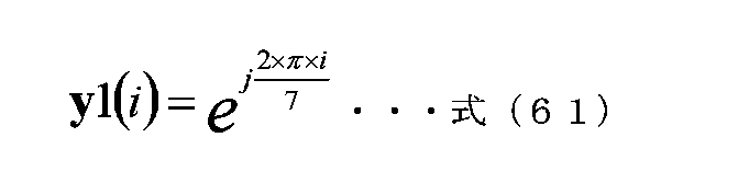
そして、位相変更部205Bは、位相変更を行わない。
・[u0 u1]=[01](u0=0,u1=1)、[u2 u3]=[11](u2=1,u3=1)のとき、基地局は、「位相変更部205A、位相変更部205Bが、方法01_4による周期的/規則的な位相変更をシンボルごとに行う」。
Then, the
- When [u0 u1] = [01] (u0 = 0, u1 = 1), [u2 u3] = [11] (u2 = 1, u3 = 1), the base station The
方法01_4:
位相変更部205Aが、位相変更を行うことにより乗算に使用する係数をy1(i)とする。iはシンボル番号を示しており、0以上の整数である。このとき、y1(i)は以下のようにあらわされる。
Method 01_4:
The

そして、位相変更部205Bは、位相変更を行わない。
表2の解釈の第3の例は以下のようになる。
・[u0 u1]=[01](u0=0,u1=1)、[u2 u3]=[00](u2=0,u3=0)のとき、基地局は、「位相変更部205A、位相変更部205Bが、方法01_1による周期的/規則的な位相変更をシンボルごとに行う」。
Then, the
A third example of the interpretation of Table 2 is as follows.
- When [u0 u1] = [01] (u0 = 0, u1 = 1), [u2 u3] = [00] (u2 = 0, u3 = 0), the base station The
方法01_1:
位相変更部205Aは、位相変更を行わない。そして、位相変更部205Bが、位相変更を行うことにより乗算に使用する係数をy2(i)とする。iはシンボル番号を示しており、0以上の整数である。このとき、y2(i)は以下のようにあらわされる。
Method 01_1:
The

・[u0 u1]=[01](u0=0, u1=1)、[u2 u3]=[01](u2=0, u3=1)のとき、基地局は、「位相変更部205A、位相変更部205Bが、方法01_2による周期的/規則的な位相変更をシンボルごとに行う」。
- When [u0 u1] = [01] (u0 = 0, u1 = 1), [u2 u3] = [01] (u2 = 0, u3 = 1), the base station The
方法01_2:
位相変更部205Aは、位相変更を行わない。そして、位相変更部205Bが、位相変更を行うことにより乗算に使用する係数をy2(i)とする。iはシンボル番号を示しており、0以上の整数である。このとき、y2(i)は以下のようにあらわされる。
Method 01_2:
The

・[u0 u1]=[01](u0=0, u1=1)、[u2 u3]=[10](u2=1, u3=0)のとき、基地局は、「位相変更部205A、位相変更部205Bが、方法01_3による周期的/規則的な位相変更をシンボルごとに行う」。
- When [u0 u1] = [01] (u0 = 0, u1 = 1), [u2 u3] = [10] (u2 = 1, u3 = 0), the base station The
方法01_3:
位相変更部205Aは、位相変更を行わない。そして、位相変更部205Bが、位相変更を行うことにより乗算に使用する係数をy2(i)とする。iはシンボル番号を示しており、0以上の整数である。このとき、y2(i)は以下のようにあらわされる。
Method 01_3:
The

・[u0 u1]=[01](u0=0, u1=1)、[u2 u3]=[11](u2=1, u3=1)のとき、基地局は、「位相変更部205A、位相変更部205Bが、方法01_4による周期的/規則的な位相変更をシンボルごとに行う」。
- When [u0 u1] = [01] (u0 = 0, u1 = 1), [u2 u3] = [11] (u2 = 1, u3 = 1), the base station The
方法01_4:
位相変更部205Aは、位相変更を行わない。そして、位相変更部205Bが、位相変更を行うことにより乗算に使用する係数をy2(i)とする。iはシンボル番号を示しており、0以上の整数である。このとき、y2(i)は以下のようにあらわされる。
Method 01_4:
The

表2の解釈の第4の例は以下のようになる。
・[u0 u1]=[01](u0=0, u1=1)、[u2 u3]=[00](u2=0, u3=0)のとき、基地局は、「位相変更部205A、位相変更部205Bが、方法01_1による周期的/規則的な位相変更をシンボルごとに行う」。
A fourth example of the interpretation of Table 2 is as follows.
- When [u0 u1] = [01] (u0 = 0, u1 = 1), [u2 u3] = [00] (u2 = 0, u3 = 0), the base station The
方法01_1:
位相変更部205Aが、位相変更を行うことにより乗算に使用する係数をy1(i)とする。iはシンボル番号を示しており、0以上の整数である。このとき、y1(i)は以下のようにあらわされる。
Method 01_1:
The

そして、位相変更部205Bが、位相変更を行うことにより乗算に使用する係数をy2(i)とする。iはシンボル番号を示しており、0以上の整数である。このとき、y2(i)は以下のようにあらわされる。
Then, the

・[u0 u1]=[01](u0=0, u1=1)、[u2 u3]=[01](u2=0, u3=1)のとき、基地局は、「位相変更部205A、位相変更部205Bが、方法01_2による周期的/規則的な位相変更をシンボルごとに行う」。
- When [u0 u1] = [01] (u0 = 0, u1 = 1), [u2 u3] = [01] (u2 = 0, u3 = 1), the base station The
方法01_2:
位相変更部205Aが、位相変更を行うことにより乗算に使用する係数をy1(i)とする。iはシンボル番号を示しており、0以上の整数である。このとき、y1(i)は以下のようにあらわされる。
Method 01_2:
The

そして、位相変更部205Bが、位相変更を行うことにより乗算に使用する係数をy2(i)とする。iはシンボル番号を示しており、0以上の整数である。このとき、y2(i)は以下のようにあらわされる。
Then, the

・[u0 u1]=[01](u0=0, u1=1)、[u2 u3]=[10](u2=1, u3=0)のとき、基地局は、「位相変更部205A、位相変更部205Bが、方法01_3による周期的/規則的な位相変更をシンボルごとに行う」。
- When [u0 u1] = [01] (u0 = 0, u1 = 1), [u2 u3] = [10] (u2 = 1, u3 = 0), the base station The
方法01_3:
位相変更部205Aが、位相変更を行うことにより乗算に使用する係数をy1(i)とする。iはシンボル番号を示しており、0以上の整数である。このとき、y1(i)は以下のようにあらわされる。
Method 01_3:
The

そして、位相変更部205Bが、位相変更を行うことにより乗算に使用する係数をy2(i)とする。iはシンボル番号を示しており、0以上の整数である。このとき、y2(i)は以下のようにあらわされる。
Then, the

・[u0 u1]=[01](u0=0, u1=1)、[u2 u3]=[11](u2=1, u3=1)のとき、基地局は、「位相変更部205A、位相変更部205Bが、方法01_4による周期的/規則的な位相変更をシンボルごとに行う」。
- When [u0 u1] = [01] (u0 = 0, u1 = 1), [u2 u3] = [11] (u2 = 1, u3 = 1), the base station The
方法01_4:
位相変更部205Aが、位相変更を行うことにより乗算に使用する係数をy1(i)とする。iはシンボル番号を示しており、0以上の整数である。このとき、y1(i)は以下のようにあらわされる。
Method 01_4:
The

そして、位相変更部205Bが、位相変更を行うことにより乗算に使用する係数をy2(i)とする。iはシンボル番号を示しており、0以上の整数である。このとき、y2(i)は以下のようにあらわされる。
Then, the

以上のように、第1の例から第4の例を記載したが、位相変更部205A、位相変更部205Bの具体的な位相変更方法は、これに限ったものではない。
<1>位相変更部205Aにおいて、周期的/規則的な位相変更をシンボルごとに行う
<2>位相変更部205Bにおいて、周期的/規則的な位相変更をシンボルごとに行う
<3>位相変更部205A、位相変更部205Bにおいて、周期的/規則的な位相変更をシンボルごとに行う
<1><2><3>のいずれか一つ以上の方法が[u2 u3]による具体的に設定されていれば上述の説明を同様に実施することができる。
As mentioned above, although the first to fourth examples have been described, the specific phase changing method of the
<1>
基地局が具備する位相変更部205A、205Bの動作を制御する、上述で説明した[u0 u1]を[u0 u1]=[10](u0=1, u1=0)と設定したとき、つまり、位相変更部205A、205Bが、特定の位相変更値(セット)で位相変更を施す場合に、具体的に行う位相変更、を設定するための制御情報をu4, u5とする。[u4 u5]と位相変更部205A、205Bが具体的に行う位相変更の関係を表3に示す。
When [u0 u1] explained above, which controls the operation of the
なお、u4, u5は、例えば、その他のシンボル403、503の制御情報シンボルの一部として、基地局が送信する、そして、端末は、その他のシンボル403、503の制御情報シンボルに含まれる[u4 u5]を得、[u4 u5]から位相変更部205A、205Bの動作を知り、データシンボルの復調及び復号を行う。そして、「具体的な位相変更」のための制御情報を2ビットとしているが、ビット数は2ビット以外であってもよい。
Note that u4 and u5 are transmitted by the base station as part of the control information symbols of other symbols 403 and 503, and the terminal transmits [u4 and u5] included in the control information symbols of other symbols 403 and 503. u5], learns the operation of the

表3の解釈の第1の例は以下のようになる。
・[u0 u1]=[10](u0=1, u1=0)、[u4 u5]=[00](u4=0, u5=0)のとき、基地局は、「位相変更部205A、位相変更部205Bが、方法10_1の特定の位相変更値(セット)で位相変更を施す」。
A first example of interpretation of Table 3 is as follows.
- When [u0 u1] = [10] (u0 = 1, u1 = 0), [u4 u5] = [00] (u4 = 0, u5 = 0), the base station The
方法10_1:
位相変更部205Aが、位相変更を行うことにより乗算に使用する係数をy1(i)とする。iはシンボル番号を示しており、0以上の整数である。このとき、y1(i)は以下のようにあらわされる。シンボル番号の依らず固定の位相値となる。
Method 10_1:
The
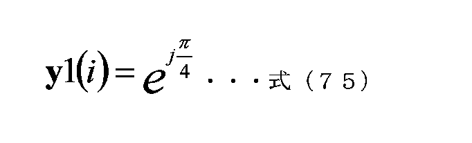
そして、位相変更部205Bは、位相変更を行わない。
・[u0 u1]=[10] (u0=1, u1=0)、[u4 u5]=[01](u4=0, u5=1)のとき、基地局は、「位相変更部205A、位相変更部205Bが、方法10_2の特定の位相変更値(セット)で位相変更を施す」。
Then, the
- When [u0 u1] = [10] (u0 = 1, u1 = 0), [u4 u5] = [01] (u4 = 0, u5 = 1), the base station The
方法10_2:
位相変更部205Aは、位相変更を行わない。そして、位相変更部205Bが、位相変更を行うことにより乗算に使用する係数をy2(i)とする。iはシンボル番号を示しており、0以上の整数である。このとき、y2(i)は以下のようにあらわされる。シンボル番号の依らず固定の位相値となる。
Method 10_2:
The

・[u0 u1]=[10] (u0=1, u1=0)、[u4 u5]=[10](u4=1, u5=0)のとき、基地局は、「位相変更部205A、位相変更部205Bが、方法10_3の特定の位相変更値(セット)で位相変更を施す」。
- When [u0 u1] = [10] (u0 = 1, u1 = 0), [u4 u5] = [10] (u4 = 1, u5 = 0), the base station The
方法10_3:
位相変更部205Aが、位相変更を行うことにより乗算に使用する係数をy1(i)とする。iはシンボル番号を示しており、0以上の整数である。このとき、y1(i)は以下のようにあらわされる。シンボル番号の依らず固定の位相値となる。
Method 10_3:
The

そして、位相変更部205Bが、位相変更を行うことにより乗算に使用する係数をy2(i)とする。iはシンボル番号を示しており、0以上の整数である。このとき、y2(i)は以下のようにあらわされる。シンボル番号の依らず固定の位相値となる。
Then, the

・[u0 u1]=[10] (u0=1, u1=0)、[u4 u5]=[11](u4=1, u5=1)のとき、基地局は、「位相変更部205A、位相変更部205Bが、方法10_4の特定の位相変更値(セット)で位相変更を施す」。
- When [u0 u1] = [10] (u0 = 1, u1 = 0), [u4 u5] = [11] (u4 = 1, u5 = 1), the base station The
方法10_4:
位相変更部205Aが、位相変更を行うことにより乗算に使用する係数をy1(i)とする。iはシンボル番号を示しており、0以上の整数である。このとき、y1(i)は以下のようにあらわされる。シンボル番号の依らず固定の位相値となる。
Method 10_4:
The

そして、位相変更部205Bが、位相変更を行うことにより乗算に使用する係数をy2(i)とする。iはシンボル番号を示しており、0以上の整数である。このとき、y2(i)は以下のようにあらわされる。シンボル番号の依らず固定の位相値となる。
Then, the

表3の解釈の第2の例は以下のようになる。
・[u0 u1]=[10](u0=1, u1=0)、[u4 u5]=[00](u4=0, u5=0)のとき、基地局は、「位相変更部205A、位相変更部205Bが、方法10_1の特定の位相変更値(セット)で位相変更を施す」。
A second example of the interpretation of Table 3 is as follows.
- When [u0 u1] = [10] (u0 = 1, u1 = 0), [u4 u5] = [00] (u4 = 0, u5 = 0), the base station The
方法10_1:
位相変更部205Aが、位相変更を行うことにより乗算に使用する係数をy1(i)とする。iはシンボル番号を示しており、0以上の整数である。このとき、y1(i)は以下のようにあらわされる。シンボル番号の依らず固定の位相値となる。
Method 10_1:
The

式(81)の場合、位相変更部205Aでは、位相を行っていない。そして、位相変更部205Bは、位相変更を行わない。
・[u0 u1]=[10] (u0=1, u1=0)、[u4 u5]=[01](u4=0, u5=1)のとき、基地局は、「位相変更部205A、位相変更部205Bが、方法10_2の特定の位相変更値(セット)で位相変更を施す」。
In the case of equation (81), the
- When [u0 u1] = [10] (u0 = 1, u1 = 0), [u4 u5] = [01] (u4 = 0, u5 = 1), the base station The
方法10_2:
位相変更部205Aが、位相変更を行うことにより乗算に使用する係数をy1(i)とする。iはシンボル番号を示しており、0以上の整数である。このとき、y1(i)は以下のようにあらわされる。シンボル番号の依らず固定の位相値となる。
Method 10_2:
The

そして、位相変更部205Bは、位相変更を行わない。
・[u0 u1]=[10] (u0=1, u1=0)、[u4 u5]=[10](u4=1, u5=0)のとき、基地局は、「位相変更部205A、位相変更部205Bが、方法10_3の特定の位相変更値(セット)で位相変更を施す」。
Then, the
- When [u0 u1] = [10] (u0 = 1, u1 = 0), [u4 u5] = [10] (u4 = 1, u5 = 0), the base station The
方法10_3:
位相変更部205Aが、位相変更を行うことにより乗算に使用する係数をy1(i)とする。iはシンボル番号を示しており、0以上の整数である。このとき、y1(i)は以下のようにあらわされる。シンボル番号の依らず固定の位相値となる。
Method 10_3:
The

そして、位相変更部205Bは、位相変更を行わない。
・[u0 u1]=[10] (u0=1, u1=0)、[u4 u5]=[11](u4=1, u5=1)のとき、基地局は、「位相変更部205A、位相変更部205Bが、方法10_4の特定の位相変更値(セット)で位相変更を施す」。
Then, the
- When [u0 u1] = [10] (u0 = 1, u1 = 0), [u4 u5] = [11] (u4 = 1, u5 = 1), the base station The
方法10_4:
位相変更部205Aが、位相変更を行うことにより乗算に使用する係数をy1(i)とする。iはシンボル番号を示しており、0以上の整数である。このとき、y1(i)は以下のようにあらわされる。シンボル番号の依らず固定の位相値となる。
Method 10_4:
The

そして、位相変更部205Bは、位相変更を行わない。
表3の解釈の第3の例は以下のようになる。
・[u0 u1]=[10](u0=1, u1=0)、[u4 u5]=[00](u4=0, u5=0)のとき、基地局は、「位相変更部205A、位相変更部205Bが、方法10_1の特定の位相変更値(セット)で位相変更を施す」。
Then, the
A third example of the interpretation of Table 3 is as follows.
- When [u0 u1] = [10] (u0 = 1, u1 = 0), [u4 u5] = [00] (u4 = 0, u5 = 0), the base station The
方法10_1:
位相変更部205Bが、位相変更を行うことにより乗算に使用する係数をy2(i)とする。iはシンボル番号を示しており、0以上の整数である。このとき、y2(i)は以下のようにあらわされる。シンボル番号の依らず固定の位相値となる。
Method 10_1:
The

式(85)の場合、位相変更部205Bでは、位相を行っていない。そして、位相変更部205Aは、位相変更を行わない。
・[u0 u1]=[10] (u0=1, u1=0)、[u4 u5]=[01](u4=0, u5=1)のとき、基地局は、「位相変更部205A、位相変更部205Bが、方法10_2の特定の位相変更値(セット)で位相変更を施す」。
In the case of equation (85), the
- When [u0 u1] = [10] (u0 = 1, u1 = 0), [u4 u5] = [01] (u4 = 0, u5 = 1), the base station The
方法10_2:
位相変更部205Bが、位相変更を行うことにより乗算に使用する係数をy2(i)とする。iはシンボル番号を示しており、0以上の整数である。このとき、y2(i)は以下のようにあらわされる。シンボル番号の依らず固定の位相値となる。
Method 10_2:
The

そして、位相変更部205Aは、位相変更を行わない。
・[u0 u1]=[10] (u0=1, u1=0)、[u4 u5]=[10](u4=1, u5=0)のとき、基地局は、「位相変更部205A、位相変更部205Bが、方法10_3の特定の位相変更値(セット)で位相変更を施す」。
Then, the
- When [u0 u1] = [10] (u0 = 1, u1 = 0), [u4 u5] = [10] (u4 = 1, u5 = 0), the base station The
方法10_3:
位相変更部205Bが、位相変更を行うことにより乗算に使用する係数をy2(i)とする。iはシンボル番号を示しており、0以上の整数である。このとき、y2(i)は以下のようにあらわされる。シンボル番号の依らず固定の位相値となる。
Method 10_3:
The

そして、位相変更部205Aは、位相変更を行わない。
・[u0 u1]=[10] (u0=1, u1=0)、[u4 u5]=[11](u4=1, u5=1)のとき、基地局は、「位相変更部205A、位相変更部205Bが、方法10_4の特定の位相変更値(セット)で位相変更を施す」。
Then, the
- When [u0 u1] = [10] (u0 = 1, u1 = 0), [u4 u5] = [11] (u4 = 1, u5 = 1), the base station The
方法10_4:
位相変更部205Bが、位相変更を行うことにより乗算に使用する係数をy2(i)とする。iはシンボル番号を示しており、0以上の整数である。このとき、y2(i)は以下のようにあらわされる。シンボル番号の依らず固定の位相値となる。
Method 10_4:
The

そして、位相変更部205Aは、位相変更を行わない。
表3の解釈の第4の例は以下のようになる。
・[u0 u1]=[10](u0=1, u1=0)、[u4 u5]=[00](u4=0, u5=0)のとき、基地局は、「位相変更部205A、位相変更部205Bが、方法10_1の特定の位相変更値(セット)で位相変更を施す」。
Then, the
A fourth example of the interpretation of Table 3 is as follows.
- When [u0 u1] = [10] (u0 = 1, u1 = 0), [u4 u5] = [00] (u4 = 0, u5 = 0), the base station The
方法10_1:
位相変更部205Aが、位相変更を行うことにより乗算に使用する係数をy1(i)とする。iはシンボル番号を示しており、0以上の整数である。このとき、y1(i)は以下のようにあらわされる。シンボル番号の依らず固定の位相値となる。
Method 10_1:
The

そして、位相変更部205Bが、位相変更を行うことにより乗算に使用する係数をy2(i)とする。iはシンボル番号を示しており、0以上の整数である。このとき、y2(i)は以下のようにあらわされる。シンボル番号の依らず固定の位相値となる。
Then, the

式(90)の場合、位相変更部205Bでは、位相を行っていない。
・[u0 u1]=[10] (u0=1, u1=0)、[u4 u5]=[01](u4=0, u5=1)のとき、基地局は、「位相変更部205A、位相変更部205Bが、方法10_2の特定の位相変更値(セット)で位相変更を施す」。
In the case of equation (90), the
- When [u0 u1] = [10] (u0 = 1, u1 = 0), [u4 u5] = [01] (u4 = 0, u5 = 1), the base station The
方法10_2:
位相変更部205Aが、位相変更を行うことにより乗算に使用する係数をy1(i)とする。iはシンボル番号を示しており、0以上の整数である。このとき、y1(i)は以下のようにあらわされる。シンボル番号の依らず固定の位相値となる。
Method 10_2:
The

そして、位相変更部205Bが、位相変更を行うことにより乗算に使用する係数をy2(i)とする。iはシンボル番号を示しており、0以上の整数である。このとき、y2(i)は以下のようにあらわされる。シンボル番号の依らず固定の位相値となる。
Then, the

・[u0 u1]=[10] (u0=1, u1=0)、[u4 u5]=[10](u4=1, u5=0)のとき、基地局は、「位相変更部205A、位相変更部205Bが、方法10_3の特定の位相変更値(セット)で位相変更を施す」。
- When [u0 u1] = [10] (u0 = 1, u1 = 0), [u4 u5] = [10] (u4 = 1, u5 = 0), the base station The
方法10_3:
位相変更部205Aが、位相変更を行うことにより乗算に使用する係数をy1(i)とする。iはシンボル番号を示しており、0以上の整数である。このとき、y1(i)は以下のようにあらわされる。シンボル番号の依らず固定の位相値となる。
Method 10_3:
The

そして、位相変更部205Bが、位相変更を行うことにより乗算に使用する係数をy2(i)とする。iはシンボル番号を示しており、0以上の整数である。このとき、y2(i)は以下のようにあらわされる。シンボル番号の依らず固定の位相値となる。
Then, the

・[u0 u1]=[10] (u0=1, u1=0)、[u4 u5]=[11](u4=1, u5=1)のとき、基地局は、「位相変更部205A、位相変更部205Bが、方法10_4の特定の位相変更値(セット)で位相変更を施す」。
- When [u0 u1] = [10] (u0 = 1, u1 = 0), [u4 u5] = [11] (u4 = 1, u5 = 1), the base station The
方法10_4:
位相変更部205Aが、位相変更を行うことにより乗算に使用する係数をy1(i)とする。iはシンボル番号を示しており、0以上の整数である。このとき、y1(i)は以下のようにあらわされる。シンボル番号の依らず固定の位相値となる。
Method 10_4:
The

式(95)の場合、位相変更部205Aでは、位相を行っていない。そして、位相変更部205Bが、位相変更を行うことにより乗算に使用する係数をy2(i)とする。iはシンボル番号を示しており、0以上の整数である。このとき、y2(i)は以下のようにあらわされる。シンボル番号の依らず固定の位相値となる。
In the case of equation (95), the

以上のように、第1の例から第4の例を記載したが、位相変更部205A、位相変更部205Bの具体的な位相変更方法は、これに限ったものではない。
<4>位相変更部205Aにおいて、特定の位相変更値(セット)で位相変更を施す。
<5>位相変更部205Bにおいて、特定の位相変更値(セット)で位相変更を施す。
<6>位相変更部205A、位相変更部205Bにおいて、特定の位相変更値(セット)で位相変更を施す。
<4><5><6>のいずれか一つ以上の方法が[u4 u5]による具体的に設定されていれば上述の説明を同様に実施することができる。
As mentioned above, although the first to fourth examples have been described, the specific phase changing method of the
<4> The
<5> The
<6> The
If one or more of the methods <4><5><6> is specifically set by [u4 u5], the above description can be implemented in the same way.
また、基地局が具備する位相変更部205A、205Bにおいて、周期的/規則的にシンボルごとに位相変更を行う方法と特定の位相変更値で位相変更を行う方法とを組み合わせることも可能である。位相変更部205A、205Bが、周期的/規則的にシンボルごとに位相変更を行う方法と特定変更値で位相変更を行う方法の組み合わせのモードを表1の「Reserve」、つまり、[u0 u1]=[11](u0=1, u1=1)に割り当てる。
Furthermore, in the
基地局が具備する位相変更部205A、205Bの動作を制御する、[u0 u1]=[11](u0=1, u1=1)と設定したとき、つまり、位相変更部205A、205Bが、周期的/規則的な位相変更をシンボルごとに行う方法と特定の位相変更値で位相変更を行う方法とを組み合わせる場合に、具体的に行う位相変更、を設定するための制御情報をu6, u7とする。[u6 u7]と位相変更部205A、205Bが具体的に行う位相変更の関係を表4に示す。
When [u0 u1] = [11] (u0 = 1, u1 = 1), which controls the operation of the
なお、u6, u7は、例えば、その他のシンボル403、503の制御情報シンボルの一部として、基地局が送信する。そして、端末は、その他のシンボル403、503の制御情報シンボルに含まれる[u6 u7]を得、[u6 u7]から位相変更部205A、205Bの動作を知り、データシンボルの復調及び復号を行う。そして、「具体的な位相変更」のための制御情報を2ビットとしているが、ビット数は、2ビット以外であってもよい。
Note that u6 and u7 are transmitted by the base station, for example, as part of the control information symbols of the other symbols 403 and 503. Then, the terminal obtains [u6 u7] included in the control information symbols of the other symbols 403 and 503, learns the operation of the

表4の解釈の第1の例は以下のとおりとなる。
・[u0 u1]=[11](u0=1, u1=1)、[u6 u7]=[00](u6=0, u7=0)のとき、基地局は、「位相変更部205A、位相変更部205Bが、方法11_1の周期的/規則的にシンボルごとに位相変更を行う方法と特定の位相変更値で位相変更を行う方法とを組み合わせる位相変更を行う」。
A first example of the interpretation of Table 4 is as follows.
- When [u0 u1] = [11] (u0 = 1, u1 = 1), [u6 u7] = [00] (u6 = 0, u7 = 0), the base station The changing
方法11_1:
位相変更部205Aが、位相変更を行うことにより乗算に使用する係数をy1(i)とする。iはシンボル番号を示しており、0以上の整数である。このとき、y1(i)は以下のようにあらわされる。
Method 11_1:
The

そして、位相変更部205Bが、位相変更を行うことにより乗算に使用する係数をy2(i)とする。iはシンボル番号を示しており、0以上の整数である。このとき、y2(i)は以下のようにあらわされる。
Then, the

・[u0 u1]=[11](u0=1, u1=1)、[u6 u7]=[01](u6=0, u7=1)のとき、基地局は、「位相変更部205A、位相変更部205Bが、方法11_2による周期的/規則的な位相変更をシンボルごとに行う方法と特定の位相変更値で位相変更を行う方法とを組み合わせる位相変更を行う」。
- When [u0 u1] = [11] (u0 = 1, u1 = 1), [u6 u7] = [01] (u6 = 0, u7 = 1), the base station The changing
方法11_2:
位相変更部205Aが、位相変更を行うことにより乗算に使用する係数をy1(i)とする。iはシンボル番号を示しており、0以上の整数である。このとき、y1(i)は以下のようにあらわされる。
Method 11_2:
The

そして、位相変更部205Bが、位相変更を行うことにより乗算に使用する係数をy2(i)とする。iはシンボル番号を示しており、0以上の整数である。このとき、y2(i)は以下のようにあらわされる。
Then, the

・[u0 u1]=[11](u0=1, u1=1)、[u6 u7]=[10](u6=1, u7=0)のとき、基地局は、「位相変更部205A、位相変更部205Bが、方法11_3による周期的/規則的な位相変更をシンボルごとに行う方法と特定の位相変更値で位相変更を行う方法とを組み合わせる位相変更を行う」。
- When [u0 u1] = [11] (u0 = 1, u1 = 1), [u6 u7] = [10] (u6 = 1, u7 = 0), the base station The changing
方法11_3:
位相変更部205Aが、位相変更を行うことにより乗算に使用する係数をy1(i)とする。iはシンボル番号を示しており、0以上の整数である。このとき、y1(i)は以下のようにあらわされる。
Method 11_3:
The

そして、位相変更部205Bが、位相変更を行うことにより乗算に使用する係数をy2(i)とする。iはシンボル番号を示しており、0以上の整数である。このとき、y2(i)は以下のようにあらわされる。
Then, the

・[u0 u1]=[11](u0=1, u1=1)、[u6 u7]=[11](u6=1, u7=1)のとき、基地局は、「位相変更部205A、位相変更部205Bが、方法11_4による周期的/規則的な位相変更をシンボルごとに行う方法と特定の位相変更値で位相変更を行う方法とを組み合わせる位相変更を行う」。
- When [u0 u1] = [11] (u0 = 1, u1 = 1), [u6 u7] = [11] (u6 = 1, u7 = 1), the base station The changing
方法11_4:
位相変更部205Aが、位相変更を行うことにより乗算に使用する係数をy1(i)とする。iはシンボル番号を示しており、0以上の整数である。このとき、y1(i)は以下のようにあらわされる。
Method 11_4:
The

そして、位相変更部205Bが、位相変更を行うことにより乗算に使用する係数をy2(i)とする。iはシンボル番号を示しており、0以上の整数である。このとき、y2(i)は以下のようにあらわされる。
Then, the

表4の解釈の第2の例は以下のとおりとなる。
・[u0 u1]=[11](u0=1, u1=1)、[u6 u7]=[00](u6=0, u7=0)のとき、基地局は、「位相変更部205A、位相変更部205Bが、方法11_1による周期的/規則的な位相変更をシンボルごとに行う方法と特定の位相変更値で位相変更を行う方法とを組み合わせる位相変更を行う」。
A second example of the interpretation of Table 4 is as follows.
- When [u0 u1] = [11] (u0 = 1, u1 = 1), [u6 u7] = [00] (u6 = 0, u7 = 0), the base station The changing
方法11_1:
位相変更部205Aが、位相変更を行うことにより乗算に使用する係数をy1(i)とする。iはシンボル番号を示しており、0以上の整数である。このとき、y1(i)は以下のようにあらわされる。
Method 11_1:
The
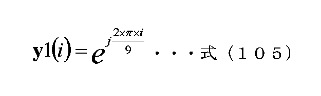
そして、位相変更部205Bが、位相変更を行うことにより乗算に使用する係数をy2(i)とする。iはシンボル番号を示しており、0以上の整数である。このとき、y2(i)は以下のようにあらわされる。
Then, the

・[u0 u1]=[11](u0=1, u1=1)、[u6 u7]=[01](u6=0, u7=1)のとき、基地局は、「位相変更部205A、位相変更部205Bが、方法11_2による周期的/規則的な位相変更をシンボルごとに行う方法と特定の位相変更値で位相変更を行う方法とを組み合わせる位相変更を行う」。
- When [u0 u1] = [11] (u0 = 1, u1 = 1), [u6 u7] = [01] (u6 = 0, u7 = 1), the base station The changing
方法11_2:
位相変更部205Aが、位相変更を行うことにより乗算に使用する係数をy1(i)とする。iはシンボル番号を示しており、0以上の整数である。このとき、y1(i)は以下のようにあらわされる。
Method 11_2:
The

そして、位相変更部205Bが、位相変更を行うことにより乗算に使用する係数をy2(i)とする。iはシンボル番号を示しており、0以上の整数である。このとき、y2(i)は以下のようにあらわされる。
Then, the

・[u0 u1]=[11](u0=1, u1=1)、[u6 u7]=[10](u6=1, u7=0)のとき、基地局は、「位相変更部205A、位相変更部205Bが、方法11_3による周期的/規則的な位相変更をシンボルごとに行う方法と特定の位相変更値で位相変更を行う方法とを組み合わせる位相変更を行う」。
- When [u0 u1] = [11] (u0 = 1, u1 = 1), [u6 u7] = [10] (u6 = 1, u7 = 0), the base station The changing
方法11_3:
位相変更部205Aが、位相変更を行うことにより乗算に使用する係数をy1(i)とする。iはシンボル番号を示しており、0以上の整数である。このとき、y1(i)は以下のようにあらわされる。
Method 11_3:
The

そして、位相変更部205Bが、位相変更を行うことにより乗算に使用する係数をy2(i)とする。iはシンボル番号を示しており、0以上の整数である。このとき、y2(i)は以下のようにあらわされる。
Then, the

・[u0 u1]=[11](u0=1, u1=1)、[u6 u7]=[11](u6=1, u7=1)のとき、基地局は、「位相変更部205A、位相変更部205Bが、方法11_4による周期的/規則的な位相変更をシンボルごとに行う方法と特定の位相変更値で位相変更を行う方法とを組み合わせる位相変更を行う」。
- When [u0 u1] = [11] (u0 = 1, u1 = 1), [u6 u7] = [11] (u6 = 1, u7 = 1), the base station The changing
方法11_4:
位相変更部205Aが、位相変更を行うことにより乗算に使用する係数をy1(i)とする。iはシンボル番号を示しており、0以上の整数である。このとき、y1(i)は以下のようにあらわされる。
Method 11_4:
The

そして、位相変更部205Bが、位相変更を行うことにより乗算に使用する係数をy2(i)とする。iはシンボル番号を示しており、0以上の整数である。このとき、y2(i)は以下のようにあらわされる。
Then, the

表4の解釈の第3の例は以下のとおりとなる。
・[u0 u1]=[11](u0=1, u1=1)、[u6 u7]=[00](u6=0, u7=0)のとき、基地局は、「位相変更部205A、位相変更部205Bが、方法11_1による周期的/規則的な位相変更をシンボルごとに行う方法と特定の位相変更値で位相変更を行う方法とを組み合わせる位相変更を行う」。
A third example of the interpretation of Table 4 is as follows.
- When [u0 u1] = [11] (u0 = 1, u1 = 1), [u6 u7] = [00] (u6 = 0, u7 = 0), the base station The changing
方法11_1:
位相変更部205Aが、位相変更を行うことにより乗算に使用する係数をy1(i)とする。iはシンボル番号を示しており、0以上の整数である。このとき、y1(i)は以下のようにあらわされる。
Method 11_1:
The

そして、位相変更部205Bが、位相変更を行うことにより乗算に使用する係数をy2(i)とする。iはシンボル番号を示しており、0以上の整数である。このとき、y2(i)は以下のようにあらわされる。
Then, the

・[u0 u1]=[11](u0=1, u1=1)、[u6 u7]=[01](u6=0, u7=1)のとき、基地局は、「位相変更部205A、位相変更部205Bが、方法11_2による周期的/規則的な位相変更をシンボルごとに行う方法と特定の位相変更値で位相変更を行う方法とを組み合わせる位相変更を行う」。
- When [u0 u1] = [11] (u0 = 1, u1 = 1), [u6 u7] = [01] (u6 = 0, u7 = 1), the base station The changing
方法11_2:
位相変更部205Aが、位相変更を行うことにより乗算に使用する係数をy1(i)とする。iはシンボル番号を示しており、0以上の整数である。このとき、y1(i)は以下のようにあらわされる。
Method 11_2:
The

そして、位相変更部205Bが、位相変更を行うことにより乗算に使用する係数をy2(i)とする。iはシンボル番号を示しており、0以上の整数である。このとき、y2(i)は以下のようにあらわされる。
Then, the

・[u0 u1]=[11](u0=1, u1=1)、[u6 u7]=[10](u6=1, u7=0)のとき、基地局は、「位相変更部205A、位相変更部205Bが、方法11_3による周期的/規則的な位相変更をシンボルごとに行う方法と特定の位相変更値で位相変更を行う方法とを組み合わせる位相変更を行う」。
- When [u0 u1] = [11] (u0 = 1, u1 = 1), [u6 u7] = [10] (u6 = 1, u7 = 0), the base station The changing
方法11_3:
位相変更部205Aが、位相変更を行うことにより乗算に使用する係数をy1(i)とする。iはシンボル番号を示しており、0以上の整数である。このとき、y1(i)は以下のようにあらわされる。
Method 11_3:
The

そして、位相変更部205Bが、位相変更を行うことにより乗算に使用する係数をy2(i)とする。iはシンボル番号を示しており、0以上の整数である。このとき、y2(i)は以下のようにあらわされる。
Then, the

・[u0 u1]=[11](u0=1, u1=1)、[u6 u7]=[11](u6=1, u7=1)のとき、基地局は、「位相変更部205A、位相変更部205Bが、方法11_4による周期的/規則的な位相変更をシンボルごとに行う方法と特定の位相変更値で位相変更を行う方法とを組み合わせる位相変更を行う」。
- When [u0 u1] = [11] (u0 = 1, u1 = 1), [u6 u7] = [11] (u6 = 1, u7 = 1), the base station The changing
方法11_4:
位相変更部205Aが、位相変更を行うことにより乗算に使用する係数をy1(i)とする。iはシンボル番号を示しており、0以上の整数である。このとき、y1(i)は以下のようにあらわされる。
Method 11_4:
The

そして、位相変更部205Bが、位相変更を行うことにより乗算に使用する係数をy2(i)とする。iはシンボル番号を示しており、0以上の整数である。このとき、y2(i)は以下のようにあらわされる。
Then, the

表4の解釈の第4の例は以下のとおりとなる。
・[u0 u1]=[11](u0=1, u1=1)、[u6 u7]=[00](u6=0, u7=0)のとき、基地局は、「位相変更部205A、位相変更部205Bが、方法11_1による周期的/規則的な位相変更をシンボルごとに行う方法と特定の位相変更値で位相変更を行う方法とを組み合わせる位相変更を行う」。
A fourth example of the interpretation of Table 4 is as follows.
- When [u0 u1] = [11] (u0 = 1, u1 = 1), [u6 u7] = [00] (u6 = 0, u7 = 0), the base station The changing
方法11_1:
位相変更部205Aが、位相変更を行うことにより乗算に使用する係数をy1(i)とする。iはシンボル番号を示しており、0以上の整数である。このとき、y1(i)は以下のようにあらわされる。
Method 11_1:
The

そして、位相変更部205Bが、位相変更を行うことにより乗算に使用する係数をy2(i)とする。iはシンボル番号を示しており、0以上の整数である。このとき、y2(i)は以下のようにあらわされる。
Then, the

・[u0 u1]=[11](u0=1, u1=1)、[u6 u7]=[01](u6=0, u7=1)のとき、基地局は、「位相変更部205A、位相変更部205Bが、方法11_2による周期的/規則的な位相変更をシンボルごとに行う方法と特定の位相変更値で位相変更を行う方法とを組み合わせる位相変更を行う」。
- When [u0 u1] = [11] (u0 = 1, u1 = 1), [u6 u7] = [01] (u6 = 0, u7 = 1), the base station The changing
方法11_2:
位相変更部205Aが、位相変更を行うことにより乗算に使用する係数をy1(i)とする。iはシンボル番号を示しており、0以上の整数である。このとき、y1(i)は以下のようにあらわされる。
Method 11_2:
The

そして、位相変更部205Bが、位相変更を行うことにより乗算に使用する係数をy2(i)とする。iはシンボル番号を示しており、0以上の整数である。このとき、y2(i)は以下のようにあらわされる。
Then, the
・[u0 u1]=[11](u0=1, u1=1)、[u6 u7]=[10](u6=1, u7=0)のとき、基地局は、「位相変更部205A、位相変更部205Bが、方法11_3による周期的/規則的な位相変更をシンボルごとに行う方法と特定の位相変更値で位相変更を行う方法とを組み合わせる位相変更を行う」。
- When [u0 u1] = [11] (u0 = 1, u1 = 1), [u6 u7] = [10] (u6 = 1, u7 = 0), the base station The changing
方法11_3:
位相変更部205Aが、位相変更を行うことにより乗算に使用する係数をy1(i)とする。iはシンボル番号を示しており、0以上の整数である。このとき、y1(i)は以下のようにあらわされる。
Method 11_3:
The

そして、位相変更部205Bが、位相変更を行うことにより乗算に使用する係数をy2(i)とする。iはシンボル番号を示しており、0以上の整数である。このとき、y2(i)は以下のようにあらわされる。
Then, the

・[u0 u1]=[11](u0=1, u1=1)、[u6 u7]=[11](u6=1, u7=1)のとき、基地局は、「位相変更部205A、位相変更部205Bが、方法11_4による周期的/規則的な位相変更をシンボルごとに行う方法と特定の位相変更値で位相変更を行う方法とを組み合わせる位相変更を行う」。
- When [u0 u1] = [11] (u0 = 1, u1 = 1), [u6 u7] = [11] (u6 = 1, u7 = 1), the base station The changing
方法11_4:
位相変更部205Aが、位相変更を行うことにより乗算に使用する係数をy1(i)とする。iはシンボル番号を示しており、0以上の整数である。このとき、y1(i)は以下のようにあらわされる。
Method 11_4:
The

そして、位相変更部205Bが、位相変更を行うことにより乗算に使用する係数をy2(i)とする。iはシンボル番号を示しており、0以上の整数である。このとき、y2(i)は以下のようにあらわされる。
Then, the

表4の解釈の第5の例は以下のとおりとなる。
・[u0 u1]=[11](u0=1, u1=1)、[u6 u7]=[00](u6=0, u7=0)のとき、基地局は、「位相変更部205A、位相変更部205Bが、方法11_1による周期的/規則的な位相変更をシンボルごとに行う方法と特定の位相変更値で位相変更を行う方法とを組み合わせる位相変更を行う」。
A fifth example of the interpretation of Table 4 is as follows.
- When [u0 u1] = [11] (u0 = 1, u1 = 1), [u6 u7] = [00] (u6 = 0, u7 = 0), the base station The changing
方法11_1:
位相変更部205Aが、位相変更を行うことにより乗算に使用する係数をy1(i)とする。iはシンボル番号を示しており、0以上の整数である。このとき、y1(i)は以下のようにあらわされる。
Method 11_1:
The

そして、位相変更部205Bが、位相変更を行うことにより乗算に使用する係数をy2(i)とする。iはシンボル番号を示しており、0以上の整数である。このとき、y2(i)は以下のようにあらわされる。
Then, the

・[u0 u1]=[11](u0=1, u1=1)、[u6 u7]=[01](u6=0, u7=1)のとき、基地局は、「位相変更部205A、位相変更部205Bが、方法11_2による周期的/規則的な位相変更をシンボルごとに行う方法と特定の位相変更値で位相変更を行う方法とを組み合わせる位相変更を行う」。
- When [u0 u1] = [11] (u0 = 1, u1 = 1), [u6 u7] = [01] (u6 = 0, u7 = 1), the base station The changing
方法11_2:
位相変更部205Aが、位相変更を行うことにより乗算に使用する係数をy1(i)とする。iはシンボル番号を示しており、0以上の整数である。このとき、y1(i)は以下のようにあらわされる。
Method 11_2:
The

そして、位相変更部205Bが、位相変更を行うことにより乗算に使用する係数をy2(i)とする。iはシンボル番号を示しており、0以上の整数である。このとき、y2(i)は以下のようにあらわされる。
Then, the

・[u0 u1]=[11](u0=1, u1=1)、[u6 u7]=[10](u6=1, u7=0)のとき、基地局は、「位相変更部205A、位相変更部205Bが、方法11_3による周期的/規則的な位相変更をシンボルごとに行う方法と特定の位相変更値で位相変更を行う方法とを組み合わせる位相変更を行う」。
- When [u0 u1] = [11] (u0 = 1, u1 = 1), [u6 u7] = [10] (u6 = 1, u7 = 0), the base station The changing
方法11_3:
位相変更部205Aが、位相変更を行うことにより乗算に使用する係数をy1(i)とする。iはシンボル番号を示しており、0以上の整数である。このとき、y1(i)は以下のようにあらわされる。
Method 11_3:
The

そして、位相変更部205Bが、位相変更を行うことにより乗算に使用する係数をy2(i)とする。iはシンボル番号を示しており、0以上の整数である。このとき、y2(i)は以下のようにあらわされる。
Then, the
・[u0 u1]=[11](u0=1, u1=1)、[u6 u7]=[11](u6=1, u7=1)のとき、基地局は、「位相変更部205A、位相変更部205Bが、方法11_4による周期的/規則的な位相変更をシンボルごとに行う方法と特定の位相変更値で位相変更を行う方法とを組み合わせる位相変更を行う」。
- When [u0 u1] = [11] (u0 = 1, u1 = 1), [u6 u7] = [11] (u6 = 1, u7 = 1), the base station The changing
方法11_4:
位相変更部205Aが、位相変更を行うことにより乗算に使用する係数をy1(i)とする。iはシンボル番号を示しており、0以上の整数である。このとき、y1(i)は以下のようにあらわされる。
Method 11_4:
The

そして、位相変更部205Bが、位相変更を行うことにより乗算に使用する係数をy2(i)とする。iはシンボル番号を示しており、0以上の整数である。このとき、y2(i)は以下のようにあらわされる。
Then, the

以上のように、第1の例から第5の例を記載したが、位相変更部205A、位相変更部205Bの具体的な位相変更方法は、これに限ったものではない。
<7>位相変更部205Aにおいて、周期的/規則的な位相変更をシンボルごとに行い、位相変更部205Bにおいて、特定の位相変更値(セット)により位相変更を行う。
<8>位相変更部205Bにおいて、特定の位変更値(セット)により、位相変更を行い、位相変更部205Bにおいて、周期的/規則的な位相変更をシンボルごとに行う。
<3>位相変更部205A、位相変更部205Bにおいて、周期的/規則的な位相変更をシンボルごとに行う。
<7><8>のいずれか一つ以上の方法が[u2 u3]による具体的に設定されていれば上述の説明を同様に実施することができる。
As mentioned above, although the first to fifth examples have been described, the specific phase changing method of the
<7> The
<8> The
<3> The
If one or more of the methods <7> and <8> are specifically set by [u2 u3], the above description can be implemented in the same way.
基地局が具備する重み付け合成部203では、重み付け合成の行列の切り替えてもよい。重み付け合成の行列を設定するための制御情報をu8, u9とする。[u8 u9]と重み付け合成部203が具体的に使用する重み付け合成の行列の関係を表5に示す。
The
なお、u8, u9は、例えば、その他のシンボル403、503の制御情報シンボルの一部として、基地局が送信する。そして、端末は、その他のシンボル403、503の制御情報シンボルに含まれる[u8 u9]を得、[u8 u9]から重み付け合成部203の動作を知り、データシンボルの復調及び復号を行う。そして、「具体的な重み付け行列」の指定のための制御情報を2ビットとしているが、ビット数は、2ビット以外であってもよい。
Note that u8 and u9 are transmitted by the base station, for example, as part of the control information symbols of the other symbols 403 and 503. Then, the terminal obtains [u8 u9] included in the control information symbols of other symbols 403 and 503, learns the operation of the

・[u8 u9]=[00](u8=0, u9=0)のとき、「基地局の重み付け合成部203において、行列1を用いたプリコーディングを行う」。
・[u8 u9]=[01](u8=0, u9=1)のとき、「基地局の重み付け合成部203において、行列2を用いたプリコーディングを行う」。
・[u8 u9]=[10](u8=1, u9=0)のとき、「基地局の重み付け合成部203において、行列3を用いたプリコーディングを行う」。
・[u8 u9]=[11](u8=1, u9=1)のとき、「基地局は、通信相手から、例えば、フィードバック情報を得、そのフィードバック情報に基づいて、基地局の重み付け合成部203において、使用するプリコーディング行列を求め、求めたプリコーディング行列を用いたプリコーディングを行う」。
- When [u8 u9] = [00] (u8 = 0, u9 = 0), "precoding is performed using
- When [u8 u9] = [01] (u8 = 0, u9 = 1), "precoding is performed using
- When [u8 u9] = [10] (u8 = 1, u9 = 0), "precoding is performed using
- When [u8 u9] = [11] (u8 = 1, u9 = 1), "The base station obtains, for example, feedback information from the communication partner, and based on that feedback information, the base station's weighted synthesis unit In
以上のようにして、基地局の重み付け合成部203は、使用するプリコーディングの行列を切り替える。そして、基地局の通信相手である端末は、制御情報シンボルに含まれるu8, u9を得、u8, u9に基づいて、データシンボルの復調及び復号を行うことができる。このようにすることで、電波伝搬環境の状態などの通信状況により、好適なプリコーディングの行列を設定することができるため、端末は、高いデータの受信品質を得ることができるという効果を得ることができる。
As described above, the
なお、表1に示したように、基地局の位相変更部205A、205Bのように指定する方法を説明したが、表1のかわりに、表6のような設定を行うようにしてもよい。
Note that, as shown in Table 1, a method of specifying the
図23の基地局の送信装置2303は、図1の構成をもつ。そして、図1の信号処理部106は、図2、図18、図19、図20、図21、図22、図28、図29、図30、図31、図32、図33のいずれかの構成をもつ。このとき、位相変更部205A、205Bの動作を通信環境や設定状況によって切り替えてもよい。そして、位相変更部205A、205Bの動作に関する制御情報を、フレーム構成図4、図5、図13、図14におけるその他のシンボル403、503の制御情報シンボルで伝送する制御情報の一部として、基地局が送信する。
The
このとき、位相変更部205A、205Bの動作に関する制御情報をu10とする。[u10]と位相変更部205A、205Bの関係を表6に示す。
At this time, control information regarding the operation of the

なお、u10は、その他のシンボル403、503の制御情報シンボルの一部として、例えば、基地局が送信する。そして、端末は、その他のシンボル403、503の制御情報シンボルに含まれる[u10]を得、[u10]から位相変更部205A、205Bの動作を知り、データシンボルの復調及び復号を行う。
Note that u10 is transmitted by, for example, the base station as part of the control information symbols of the other symbols 403 and 503. Then, the terminal obtains [u10] included in the control information symbols of the other symbols 403 and 503, learns the operation of the
表6の解釈は以下のようになる。
・「位相変更部205A、205Bは位相変更を行わない。」と基地局が設定したとき、「u10=0」と設定する。よって、位相変更部205Aは、入力信号204Aに対し、位相変更を行わずに、信号206Aを出力する。同様に、位相変更部205Bは、入力信号(204B)に対し、位相変更を行わずに、信号(206B)を出力する。
・「位相変更部205A、205Bが、周期的/規則的な位相変更をシンボルごとに行う。」と基地局が設定したとき、「u10=1」と設定する。なお、位相変更部205A、205Bが、「シンボルごとに施す周期的/規則的な位相変更」を変更する方法の詳細については、実施の形態1から実施の形態6で説明したとおりであるので、詳細の説明を省略する。そして、図1の信号処理部106が、図20、図21、図22のいずれかの構成を持つ場合、「位相変更部205Aが周期的/規則的な位相変更をシンボルごとに行い、位相変更部205Bが周期的/規則的な位相変更をシンボルごとに行わない」「位相変更部205Aが周期的/規則的な位相変更をシンボルごとに行わない、位相変更部205Bが周期的/規則的な位相変更をシンボルごとに行う」ときについても「u10=1」と設定する。
The interpretation of Table 6 is as follows.
- When the base station sets "The
- When the base station sets "The
以上のようにして、電波伝搬環境などの通信状況により、位相変更部205A、205Bの位相変更の動作のON/OFFを行うことで、端末は、高いデータの受信品質を得ることができるという効果を得ることができる。
As described above, by turning on/off the phase changing operation of the
図23の基地局の送信装置2303は、図1の構成をもつ。そして、図1の信号処理部106は、図2、図18、図19、図20、図21、図22、図28、図29、図30、図31、図32、図33のいずれかの構成をもつ。このとき、位相変更部209A、209Bの動作を通信環境や設定状況によって切り替えてもよい。そして、位相変更部209A、209Bの動作に関する制御情報を、フレーム構成図4、図5、図13、図14におけるその他のシンボル403、503の制御情報シンボルで伝送する制御情報の一部として、基地局が送信する。
The
このとき、位相変更部209A、209Bの動作に関する制御情報をu11とする。[u11]と位相変更部209A、209Bの関係を表7に示す。
At this time, control information regarding the operation of the

なお、u11は、その他のシンボル403、503の制御情報シンボルの一部として、例えば、基地局が送信する。そして、端末は、その他のシンボル403、503の制御情報シンボルに含まれる[u11]を得、[u11]から位相変更部209A、209Bの動作を知り、データシンボルの復調及び復号を行う。
Note that u11 is transmitted by, for example, the base station as part of the control information symbols of the other symbols 403 and 503. Then, the terminal obtains [u11] included in the control information symbols of the other symbols 403 and 503, learns the operation of the
表7の解釈は以下のようになる。
・「位相変更部209A、209Bは位相変更を行わない。」と基地局が設定したとき、「u11=0」と設定する。よって、位相変更部209Aは、入力信号(208A)に対し、位相変更を行わずに、信号(210A)を出力する。同様に、位相変更部209Bは、入力信号(208B)に対し、位相変更を行わずに、信号(210B)を出力する。
・「位相変更部209A、209Bが、周期的/規則的な位相変更をシンボルごとに行う。または、サイクリックディレイダイバーシチを適用する。」と基地局が設定したとき、「u11=1」と設定する。
The interpretation of Table 7 is as follows.
- When the base station sets "The
- When the base station sets "The
なお、位相変更部209A、209Bが、周期的/規則的にシンボルごとに位相変更を変更する方法の詳細については、実施の形態1から実施の形態6で説明したとおりであるので、詳細の説明を省略する。そして、図1の信号処理部106が、図19、図22のいずれかの構成を持つ場合、「位相変更部209Aが周期的/規則的な位相変更をシンボルごとに行い、位相変更部209Bが周期的/規則的な位相変更をシンボルごとに行わない」「位相変更部209Aが周期的/規則的な位相変更をシンボルごとに行わない、位相変更部209Bが周期的/規則的な位相変更をシンボルごとに行う」ときについても「u11=1」と設定する。
Note that the details of the method by which the
以上のようにして、電波伝搬環境などの通信状況により、位相変更部209A、209Bの位相変更の動作のON/OFFを行うことで、端末は、高いデータの受信品質を得ることができるという効果を得ることができる。
As described above, by turning on/off the phase changing operation of the
次に、表1のように位相変更部205A、205Bの動作を切り替える一例を説明する。
Next, an example of switching the operations of the
例えば、基地局と端末は、図27のような通信を行っている。なお、図27に基づいた通信については、前に説明したので、説明の一部を省略する。 For example, a base station and a terminal communicate as shown in FIG. 27. Note that the communication based on FIG. 27 has been explained previously, so a part of the explanation will be omitted.
まず、端末は、基地局に対し、通信の要求を行う。 First, the terminal makes a communication request to the base station.
すると、基地局は、表1の「特定の位相変更値(セット)で位相変更を施す」を選択し、位相変更部205A、および/または、位相変更部205Bは、「特定の位相変更値(セット)で位相変更を施す」に相当する信号処理を施し、データシンボル#1 2702_1を送信する。
Then, the base station selects "perform phase change using a specific phase change value (set)" in Table 1, and the
端末は、基地局が送信した制御情報シンボル2701_1およびデータシンボル#1 2702_1を受信し、制御情報シンボル2701_1に含まれる送信方法に基づいて、データシンボル#1 2702_1を復調及び復号する。その結果、「データシンボル#1 2702_1に含まれるデータが誤りなく得られた」と、端末が判断した。すると、端末は、「データシンボル#1 2702_1に含まれるデータが誤りなく得られた」という情報を少なくとも含む端末送信シンボル2750_1を基地局に対し、送信する。
The terminal receives control information symbol 2701_1 and
基地局は、端末が送信した端末送信シンボル2750_1を受信し、端末送信シンボル2750_1に含まれる少なくとも「データシンボル#1 2702_1に含まれるデータが誤りなく得られた」の情報に基づき、位相変更部205A、および/または、位相変更部205Bで施す位相変更(セット)を、データシンボル#1 2702_1を送信するときと同様に、「特定の位相変更値(セット)で位相変更を施す」と決定をする。
The base station receives the terminal transmission symbol 2750_1 transmitted by the terminal, and based on the information included in the terminal transmission symbol 2750_1 that at least "the data included in
基地局は、「データシンボル#1 2702_1に含まれるデータが誤りなく得られた」ので、次のデータシンボルを送信する際も、「特定の位相変更値(セット)で位相変更を施す」を使用しても、端末は、誤りなくデータを得ることができる可能性が高いと判断することができる。
Since "the data included in
これにより、端末は高いデータの受信品質を得ることができる可能性が高いという効果を得ることができる。そして、基地局は、決定した「特定の位相変更値(セット)で位相変更を施す」に基づき、位相変更部205A、および/または、位相変更部205Bにおいて、位相変更を施す。
Thereby, the terminal can obtain the effect that there is a high possibility of obtaining high data reception quality. Then, the base station performs a phase change in the
基地局は、制御情報シンボル2701_2、および、データシンボル#2 2702_2を送信するが、少なくともデータシンボル#2 2702_2は、決定した「特定の位相変更値(セット)で位相変更を施す」による位相変更が行われる。
The base station transmits the control information symbol 2701_2 and the
端末は、基地局が送信した制御情報シンボル2701_2およびデータシンボル#2 2702_2を受信し、制御情報シンボル2701_2に含まれる送信方法に関する情報に基づいて、データシンボル#2 2702_2を復調及び復号する。その結果、「データシンボル#2 2702_2 に含まれるデータが正しく得られなかった」と、端末が判断した。
The terminal receives control information symbol 2701_2 and
すると、端末は、「データシンボル#2 2702_2に含まれるデータが正しく得られなかった」という情報を少なくとも含む端末送信シンボル2750_2を基地局に対し、送信する。
Then, the terminal transmits to the base station a terminal transmission symbol 2750_2 that includes at least the information that "the data included in
基地局は、端末が送信した端末送信シンボル2750_2を受信し、端末送信シンボル2750_2に含まれる少なくとも「データシンボル#2 2702_2に含まれるデータが正しく得られなかった」の情報に基づき、位相変更部205A、および/または、位相変更部205Bで施す位相変更を、「シンボルごとに位相変更値を周期的/規則的に変更する」に変更すると判断する。
The base station receives the terminal transmission symbol 2750_2 transmitted by the terminal, and based on the information included in the terminal transmission symbol 2750_2 that at least "the data included in
基地局は、「データシンボル#2 2702_2に含まれるデータが正しく得られなかった」ので、次のデータシンボルを送信する際、「周期的/規則的な位相変更をシンボルごとに行う」に位相変更方法を変更すると、端末は、誤りなくデータを得ることができる可能性が高いと判断することができる。
Since "the data included in
これにより、端末は高いデータの受信品質を得ることができる可能性が高いという効果を得ることができる。したがって、基地局は、「周期的/規則的な位相変更をシンボルごとに行う」に基づき、位相変更部205A、および/または、位相変更部205Bにおいて、位相変更を施す。
Thereby, the terminal can obtain the effect that there is a high possibility of obtaining high data reception quality. Therefore, the base station performs a phase change in the
このとき、制御情報シンボル2701_3と「データシンボル#2 2702_2-1」を基地局は、送信するするが、少なくとも、「データシンボル#2 2702_2-1」に対して、「周期的/規則的な位相変更をシンボルごとに行う」に基づいた位相変更を行う。
At this time, the base station transmits the control information symbol 2701_3 and "
端末は、基地局が送信した制御情報シンボル2701_3およびデータシンボル#2 2702_2を受信し、制御情報シンボル2701_3に含まれる送信方法の情報に基づいて、データシンボル#2 2702_2-1を復調及び復号する。その結果、「データシンボル#2 2702_2-1に含まれるデータが正しく得られなかった」と、端末が判断した。すると、端末は、「データシンボル#2 2702_2-1に含まれるデータが正しく得られなかった」という情報を少なくとも含む端末送信シンボル2750_3を基地局に対し、送信する。
The terminal receives control information symbol 2701_3 and
基地局は、端末が送信した端末送信シンボル2750_3を受信し、端末送信シンボル2750_3に含まれる少なくとも「データシンボル#2 2702_2-1に含まれるデータが正しく得られなかった」情報に基づき、位相変更部A、および、位相変更部Bで施す位相変更を、再度、「周期的/規則的な位相変更をシンボルごとに行う」に設定すると判断する。したがって、基地局は、「周期的/規則的な位相変更をシンボルごとに行う」に基づき、位相変更部205A、および/または、位相変更部205Bにおいて、位相変更を施す。このとき、制御情報シンボル2701_4と「データシンボル#2 2702_2-2」を基地局は、送信するが、少なくとも、「データシンボル#2 2702_2-2」に対して、「周期的/規則的な位相変更をシンボルごとに行う」に基づいた位相変更を行う。
The base station receives the terminal transmission symbol 2750_3 transmitted by the terminal, and based on the information included in the terminal transmission symbol 2750_3 that at least "the data included in
端末は、基地局が送信した制御情報シンボル2701_4およびデータシンボル#2 2702_2-2を受信し、制御情報シンボル2701_4に含まれている送信方法に関する情報に基づいて、データシンボル#2 2702_2-2を復調及び復号する。その結果、「データシンボル#2 2702_2-2に含まれているデータが誤りなく得られた」と、端末が判断した。すると、端末は、「データシンボル#2 2702_2-2に含まれているデータが誤りなく得られた」という情報を少なくとも含む端末送信シンボル2750_4を基地局に対し、送信する。
The terminal receives the control information symbol 2701_4 and the
基地局は、端末が送信した端末送信シンボル2750_4を受信し、端末送信シンボル2750_4に含まれる少なくとも「データシンボル#2 2702-2に含まれるデータが誤りなく得られた」の情報に基づき、位相変更部205A、および/または、位相変更部205Bで施す位相変更(セット)を、「特定の位相変更値(セット)で位相変更を施す」と決定をする。そして、基地局は、「特定の位相変更値(セット)で位相変更を施す」に基づき、位相変更部205A、および/または、位相変更部205Bにおいて、位相変更を施す。
The base station receives the terminal transmission symbol 2750_4 transmitted by the terminal, and changes the phase based on at least the information "the data included in
基地局は、制御情報シンボル2701_5、および、データシンボル#3 2702_3を送信するが、少なくともデータシンボル#3 2702_3は、「特定の位相変更値(セット)で位相変更を施す」に基づく、位相変更が行われる。
The base station transmits the control information symbol 2701_5 and the
端末は、基地局が送信した制御情報シンボル2701_5およびデータシンボル#3 2702_3を受信し、制御情報シンボル2701_5に含まれている送信方法に関する情報に基づいて、データシンボル#3 2702_3を復調及び復号する。その結果、「データシンボル#3 2702_3に含まれるデータが誤りなく得られた」と、端末が判断した。すると、端末は、「データシンボル#3 2702_3に含まれるデータが誤りなく得られた」という情報を少なくとも含む端末送信シンボル2750_5を基地局に対し、送信する。
The terminal receives control information symbol 2701_5 and
基地局は、端末が送信した端末送信シンボル2750_5を受信し、端末送信シンボル2750_5に含まれる少なくとも「データシンボル#3 2702_3に含まれるデータが誤りなく得られた」の情報に基づき、位相変更部205A」、および/または、位相変更部205Bで施す方法を「特定の位相変更値(セット)で位相変更を施す」方法と決定する。そして、基地局は、「特定の位相変更値(セット)で位相変更を施す」に基づき、データシンボル#4 2702_4を送信する。
The base station receives the terminal transmission symbol 2750_5 transmitted by the terminal, and based on the information included in the terminal transmission symbol 2750_5 that at least "the data included in
端末は、基地局が送信した制御情報シンボル2701_6およびデータシンボル#4 2702_4を受信し、制御情報シンボル2701_6に含まれる送信方法に関する情報に基づき、データシンボル#4 2702_4を復調及び復号する。その結果、「データシンボル#4 2702_4に含まれるデータが正しく得られなかった」と、端末が判断した。すると、端末は「データシンボル#4 2702_4に含まれるデータが正しく得られなかった」という情報を少なくとも含む端末送信シンボル2750_6を基地局に対し、送信する。
The terminal receives control information symbol 2701_6 and
基地局は、端末が送信した端末送信シンボル2750_6を受信し、端末送信シンボル2750_6に含まれる少なくとも「データシンボル#4 2702_4に含まれるデータが正しく得られなかった」の情報に基づき、位相変更部205A、および/または、位相変更部205Bで施す位相変更を、「周期的/規則的な位相変更をシンボルごとに行う」に変更すると判断する。したがって、基地局は、「周期的/規則的な位相変更をシンボルごとに行う」に基づき、位相変更部205A、および/または、位相変更部205Bにおいて、位相変更を施す。このとき、制御情報シンボル2701_7と「データシンボル#4 2702_4-1」を基地局は、送信するが、少なくとも、「データシンボル#4 2702_4-1」に対して、「周期的/規則的な位相変更をシンボルごとに行う」に基づいた位相変更を行う。
The base station receives the terminal transmission symbol 2750_6 transmitted by the terminal, and changes the
端末は、基地局が送信した制御情報シンボル2701_7およびデータシンボル#4 2702_4-1を受信し、制御情報シンボル2701_7に含まれる送信方法に関する情報に基づいて、データシンボル#4 2702_4-1を復調及び復号する。
The terminal receives the control information symbol 2701_7 and the
なお、データシンボル#1 2702_1、データシンボル#2 2702_2、データシンボル#3 2702_3、データシンボル#4 2702_4において、実施の形態1から実施の形態6で説明したように、基地局は、複数の変調信号を複数のアンテナから送信する。
Note that in
図27の基地局、端末のフレーム構成はあくまでも一例であり、他のシンボルが含まれていてもよい。そして、制御情報シンボル2701_1、2701_2、2701_3、2701_4、2701_5、2701_6、データシンボル#1 2702_1、データシンボル#2 2702_2、データシンボル#3 2702_3、データシンボル#4 2702_4のそれぞれのシンボルは、例えば、パイロットシンボルのような他のシンボルを含んでいてもよい。また、制御情報シンボル2701_1、2701_2、2701_3、2701_4、2701_5、2701_6には、データシンボル#1 2702_1、データシンボル#2 2702_2、データシンボル#3 2702_3、データシンボル#4 2702_4を送信する際に使用した「特定の位相変更値」の値に関する情報を含んでおり、端末は、この情報を得ることで、データシンボル#1 2702_1、データシンボル#2 2702_2、データシンボル#3 2702_3、データシンボル#4 2702_4の復調及び復号が可能となる。
The frame structure of the base station and terminal in FIG. 27 is just an example, and other symbols may be included. Each of the control information symbols 2701_1, 2701_2, 2701_3, 2701_4, 2701_5, 2701_6,
なお、図27を用いた、基地局の本実施の形態で記載した「表1」に基づく送信方法の切り替えについては、上述に限ったものではなく、上述の説明は、送信方法切り替えの一例でしかなく、より、柔軟に「表1」に基づく送信方法の切り替えを行ってもよい。 Note that the switching of the transmission method based on "Table 1" described in this embodiment of the base station using FIG. 27 is not limited to the above, and the above explanation is an example of switching the transmission method. However, the transmission method may be switched more flexibly based on "Table 1".
以上のように、送信方法の切り替え、位相変更方法の切り替え、位相変更の動作のON/OFFを、通信環境等により、より柔軟に動作を切り替えることで、通信相手の受信装置は、データの受信品質が向上するという効果を得ることができる。 As described above, by switching the transmission method, switching the phase change method, and turning ON/OFF the phase change operation more flexibly depending on the communication environment, the receiving device of the communication partner can receive data. The effect of improving quality can be obtained.
なお、本実施の形態の表1のu0=1かつu1=1のReserveに対し、通信相手からの情報などによって、プリコーディング行列を切り替える方式を割り当ててもよい。つまり、基地局は、MIMO伝送方式を選択した際、通信相手からの情報に基づき、プリコーディング行列を選択する方式を選ぶことができるようにしてもよい。 Note that a method for switching the precoding matrix may be assigned to Reserve with u0=1 and u1=1 in Table 1 of this embodiment based on information from the communication partner. That is, when the base station selects the MIMO transmission method, the base station may be able to select the method for selecting the precoding matrix based on information from the communication partner.
本実施の形態において、図1の信号処理部106の構成として、図28、図29、図30、図31、図32、図33について説明を行ったが、実施の形態1から実施の形態6に対し、図1の信号処理部106として、図28、図29、図30、図31、図32、図33を適用しても、実施することが可能である。
In this embodiment, FIGS. 28, 29, 30, 31, 32, and 33 have been described as the configuration of the
(補足3)
本開示で記載したマッピング部において、シンボルごとにマッピングの方法を、例えば、規則的/周期的に切り替えてもよい。例えば、変調方式として、同相I-直交Q平面において、4ビット伝送のための16個の信号点をもつ変調方式と設定した。このとき、シンボルごとに、同相I-直交Q平面における4ビットを伝送するための16個の信号点の配置を切り替えてもよい。
(Supplement 3)
In the mapping unit described in this disclosure, the mapping method may be switched regularly/periodically for each symbol, for example. For example, the modulation method is set to have 16 signal points for 4-bit transmission in the in-phase I-quadrature Q plane. At this time, the arrangement of 16 signal points for transmitting 4 bits in the in-phase I-quadrature Q plane may be switched for each symbol.
また、実施の形態1から実施の形態6において、OFDMなどのマルチキャリア方式に適用した場合について説明したが、シングルキャリア方式に適用しても同様に実施することは可能である。
Further, in
また、本開示の各実施の形態において、スペクトル拡散通信方式を適用した場合についても同様に実施することが可能である。 Further, in each embodiment of the present disclosure, it is possible to implement the spread spectrum communication method in the same manner.
(補足4)
本開示で開示した各実施の形態において、送信装置の構成として図1を例に挙げて説明し、図1の信号処理部106の構成として、図2、図18、図19、図20、図21、図22、図28、図29、図30、図31、図32、図33を例に挙げて説明した。しかしながら、送信装置の構成は図1で説明した構成に限られず、信号処理部106の構成は、図2、図18、図19、図20、図21、図22、図28、図29、図30、図31、図32、図33で示した構成に限られない。すなわち、送信装置が本開示で開示した各実施の形態において説明した信号処理後の信号106_A、106_Bのいずれかと同じ信号を生成し、複数のアンテナ部を用いて送信することができれば、送信装置及びその信号処理部106は、どのような構成でもよい。
(Supplement 4)
In each embodiment disclosed in this disclosure, the configuration of the transmitter will be described using FIG. 1 as an example, and the configuration of the
以下では、そのような条件を満たす、送信装置及びその信号処理部106の異なる構成例について説明する。 Below, different configuration examples of the transmitting device and its signal processing unit 106 that satisfy such conditions will be explained.
異なる構成例の一つとしては、図1のマッピング部104が、符号化データ103及び制御信号100に基づいて、図2、図18、図19、図20、図21、図22のいずれかにおける重み付け合成後の信号204A、204Bに相当する信号を、マッピング後の信号105_1、105_2として生成する。信号処理部106は、図2、図18、図19、図20、図21、図22のいずれかから重み付け合成部203を除いた構成を備え、マッピング後の信号105_1が位相変更部205Aまたは挿入部207Aに入力され、マッピング後の信号105_2が位相変更部205Bまたは挿入部207Bに入力される。
As one example of a different configuration, the
また、異なる構成例の別の一つとしては、重み付け合成(プリコーディング)の処理が、式(33)または式(34)で示す(プリコーディング)行列Fであらわされる場合、図2における重み付け合成部203は、マッピング後の信号201A、201Bに対し、重み付け合成のための信号処理を施さずに、マッピング後の信号201Aを重み付け合成後の信号204Aとして出力し、マッピング後の信号201Bを重み付け合成後の信号204Bとして出力する。
In addition, as another example of a different configuration, when the weighted combination (precoding) process is expressed by the (precoding) matrix F shown in equation (33) or equation (34), the weighted combination in FIG. The
この場合、重み付け合成部203は、制御信号200に基づいて、(i)重み付け合成に対応する信号処理を施して重み付け合成後の信号204A、204Bを生成する、(ii)重み付け合成のための信号処理を行わず、マッピング後の信号201Aを重み付け合成後の信号204Aとして出力し、マッピング後の信号201Bを重み付け合成後の信号204Bとして出力する、という(i)の処理と(ii)の処理を切り替える制御を行う。また、重み付け合成(プリコーディング)の処理として、式(33)または式(34)の(プリコーディング)行列Fであらわされるものしか実施しない場合、重み付け合成部203を備えていなくてもよい。
In this case, based on the
このように、送信装置の具体的な構成が異なっていたとしても、本開示で開示した各実施の形態において説明した信号処理後の信号106_A、106_Bのいずれかと同じ信号を生成し、複数のアンテナ部を用いて送信すれば、受信装置は、直接波が支配的な環境、例えば、LOS環境のときに、MIMO伝送を行っている、又は、複数のストリームを伝送しているデータシンボルの受信装置におけるデータの受信品質が向上するという効果を得ることができる。 In this way, even if the specific configuration of the transmitting device is different, the same signal as either the signal 106_A or 106_B after signal processing described in each embodiment disclosed in this disclosure is generated, and multiple antennas are used. If the data symbol is transmitted using a data symbol, the receiving device is performing MIMO transmission or transmitting a plurality of streams in an environment where direct waves are dominant, for example, a LOS environment. It is possible to obtain the effect that the reception quality of data is improved.
なお、図1の信号処理部106において、重み付け合成部203の前と後ろの両方に位相変更部を設けてもよい。具体的には、信号処理部106は、重み付け合成部203の前段に、マッピング後の信号201Aに対して位相変更を施して位相変更後の信号2801Aを生成する位相変更部205A_1、及びマッピング後の信号201Bに対して位相変更を施して位相変更後の信号2801Bを生成する位相変更部205B_1のいずれか一方または両方を備える。
Note that in the
さらに、信号処理部106は、挿入部207A、207Bの前段に、重み付け合成後の信号204Aに対して位相変更を施して位相変更後の信号206Aを生成する位相変更部205A_2、及び重み付け合成後の信号204Bに対して位相変更を施して位相変更後の信号206Bを生成する位相変更部205B_2のいずれか一方または両方を備える。
Further, the
ここで、信号処理部106が位相変更部205A_1を備える場合、重み付け合成部203一方の入力は位相変更後の信号2801Aであり、信号処理部106が位相変更部205A_1を備えない場合、重み付け合成部203一方の入力はマッピング後の信号201Aである。
Here, when the
信号処理部106が位相変更部205B_1を備える場合、重み付け合成部203の他方の入力は位相変更後の信号2801Bであり、信号処理部106が位相変更部205B_1を備えない場合、重み付け合成部203の他方の入力はマッピング後の信号201Bである。信号処理部106が位相変更部205A_2を備える場合、挿入部207Aの入力は位相変更後の信号206Aであり、信号処理部106が位相変更部205A_2を備えない場合、挿入部207Aの入力は重み付け合成後の信号204Aである。
When the
そして、信号処理部106が位相変更部205B_2を備える場合、挿入部207Bの入力は位相変更後の信号206Bであり、信号処理部106が位相変更部205B_2を備えない場合、挿入部207Bの入力は重み付け合成後の信号204Bである。
When the
また、図1の送信装置は、信号処理部106の出力である信号処理後の信号106_A、106_Bに対し、別の信号処理を施す第2の信号処理部を備えていてもよい。このとき、第2の信号処理部が出力する2つの信号を第2の信号処理後の信号A、第2の信号処理後の信号Bとすると、無線部107_Aは、第2の信号処理後の信号Aを入力とし、所定の処理を施し、無線部107_Bは、第2の信号処理後の信号Bを入力とし、所定の処理を施す。
Further, the transmitting device in FIG. 1 may include a second signal processing unit that performs another signal processing on the signal-processed signals 106_A and 106_B that are output from the
(実施の形態A1)
以下では、基地局(AP)と端末が通信を行っている場合について説明する。このとき、基地局(AP)は、複数のストリームのデータを含む複数の変調信号を複数のアンテナを用いて送信することができる。
(Embodiment A1)
In the following, a case where a base station (AP) and a terminal are communicating will be described. At this time, the base station (AP) can transmit multiple modulated signals including data of multiple streams using multiple antennas.
例えば、基地局(AP)は、複数のストリームのデータを含む複数の変調信号を複数のアンテナを用いて送信するために、図1の送信装置を備える。また、図1の信号処理部106の構成として、例えば、図2、図18、図19、図20、図21、図22、図28、図29、図30、図31、図32、図33の構成のいずれかを備える。
For example, a base station (AP) includes the transmitting device of FIG. 1 in order to transmit multiple modulated signals including multiple streams of data using multiple antennas. Further, as the configuration of the
上述した送信装置では、プリコーディング後の、少なくとも一つの変調信号に対し、位相変更を行う場合について説明している。本実施の形態では、基地局(AP)は、「位相変更を行う、位相変更を行わない」、を制御信号により切り替え可能である。したがって、以下のようになる。 In the transmitting device described above, a case is described in which the phase is changed for at least one modulated signal after precoding. In this embodiment, the base station (AP) can switch between "performing phase change and not performing phase change" using a control signal. Therefore, it becomes as follows.
<位相変更を行う場合>
基地局(AP)は少なくとも一つの変調信号に対し、位相変更を行う。そして、複数の変調信号を複数のアンテナを用いて送信する。なお、少なくとも一つの変調信号に対し、位相変更を行い、複数の変調信号を複数のアンテナを用いて送信する送信方法については、本開示の複数の実施の形態において説明したとおりである。
<When changing the phase>
A base station (AP) changes the phase of at least one modulated signal. Then, multiple modulated signals are transmitted using multiple antennas. Note that the transmission method of changing the phase of at least one modulated signal and transmitting multiple modulated signals using multiple antennas is as described in multiple embodiments of the present disclosure.
<位相変更を行わない場合>
基地局(AP)は、複数のストリームの変調信号(ベースバンド信号)に対し、本開示で説明したプリコーディング(重み付け合成)を行い、位相変更は施さないで、生成された複数の変調信号を複数のアンテナを用いて送信する。ただし、本開示で上述したように、プリコーディング部(重み付け合成部)は、プリコーディングの処理を行わない場合があってもよいし、常にプリコーディングの処理を行わずプリコーディング部(重み付け合成部)を備えていなくてもよい。
<When not changing the phase>
A base station (AP) performs precoding (weighted synthesis) as described in this disclosure on modulated signals (baseband signals) of multiple streams, and converts the generated multiple modulated signals without changing the phase. Transmit using multiple antennas. However, as described above in this disclosure, the precoding unit (weighted synthesis unit) may not perform the precoding process, or may not always perform the precoding process and the precoding unit (weighted synthesis unit) ) may not be provided.
なお、基地局(AP)は、例えば、プリアンブルを用いて、位相変更を行う/行わないを通信相手である端末に通知するための制御情報を送信する。 Note that the base station (AP) uses, for example, a preamble to transmit control information for notifying a communication partner terminal whether to perform or not to change the phase.
図34は、基地局(AP)3401と端末3402が通信を行っている状態におけるシステム構成の一例を示している。
FIG. 34 shows an example of a system configuration in a state where a base station (AP) 3401 and a
図34に示しているように、基地局(AP)3401が変調信号を送信し、通信相手である端末3402がその変調信号を受信する。そして、端末3402が変調信号を送信し、通信相手である基地局3401がその変調信号を受信する。
As shown in FIG. 34, a base station (AP) 3401 transmits a modulated signal, and a
図35は、基地局(AP)3401と端末3402の通信のやりとりの例を示している。
FIG. 35 shows an example of communication exchange between a base station (AP) 3401 and a
図35において、図35における(A)は基地局(AP)3401の送信信号の時間における様子を示しており、横軸は時間である。図35における(B)は端末3402の送信信号の時間における様子を示しており、横軸は時間である。
In FIG. 35, (A) in FIG. 35 shows the state of the transmission signal of the base station (AP) 3401 over time, and the horizontal axis is time. (B) in FIG. 35 shows the state of the transmission signal of the
まず、基地局(AP)3401は、例えば変調信号を送信したいという要求情報を含んだ送信要求3501を送信する。
First, the base station (AP) 3401 transmits a
そして、端末3402は、基地局(AP)3401が送信した変調信号を送信したいという要求情報である送信要求3501を受信し、例えば端末3402が受信可能な能力(もしくは受信可能な方式)を示す情報を含んだ受信能力通知シンボル3502を送信する。
Then, the
基地局(AP)3401は、端末3402が送信した受信能力通知シンボル3502を受信し、受信能力通知シンボル3502に含まれる情報の内容に基づいて、誤り訂正符号化方法、変調方式(または、変調方式のセット)、送信方法を決定し、これらの決定した方法に基づいて、送信したい情報(データ)に対し、誤り訂正符号化、変調方式におけるマッピング、その他の信号処理(例えば、プリコーディング、位相変更など)を施して生成された、データシンボル等を含む変調信号3503を送信する。
The base station (AP) 3401 receives the reception
なお、データシンボル等3503には、例えば、制御情報シンボルが含まれていてもよい。このとき、データシンボルを、「複数ストリームのデータを含む複数の変調信号を複数のアンテナを用いて送信する送信方法」を用いて送信する際、少なくとも一つの変調信号に対し位相変更を行っているか、または、前述の位相変更を行っていないか、を通信相手に通知するための情報を含む制御シンボルを送信しているとよい。通信相手が容易に復調方法変更することができる。 Note that the data symbols etc. 3503 may include, for example, control information symbols. At this time, when transmitting data symbols using a "transmission method in which multiple modulated signals containing multiple streams of data are transmitted using multiple antennas," is the phase of at least one modulated signal changed? Alternatively, it is preferable to transmit a control symbol that includes information for notifying the communicating party whether or not the above-mentioned phase change is being performed. The communication partner can easily change the demodulation method.
端末3402は、基地局3401が送信したデータシンボル等3503を受信し、データを得る。
The
図36は、図35で示した端末が送信する受信能力通知シンボル3502が含むデータの例を示している。図36は、「位相変更の復調に対応している/対応していない」に関する情報を示すデータ3601、「受信指向性制御に対応している/対応していない」に関する情報を示すデータ3602を示す。
FIG. 36 shows an example of data included in reception
なお、「位相変更の復調に対応している/対応していない」に関する情報を示すデータ3601において、「対応している」とは、例えば、以下の状態を示す。
Note that in the
「位相変更の復調に対応している」:
・基地局(AP)3401は少なくとも一つの変調信号に対し、位相変更を行い、複数の変調信号を複数のアンテナを用いて送信した際、端末3402は、この変調信号を受信し、復調することができる、ということを意味している。つまり、位相変更を考慮した復調を行うことができ、データを得ることができるということを意味している。なお、少なくとも一つの変調信号に対し、位相変更を行い、複数の変調信号を複数のアンテナを用いて送信する送信方法については、本開示の複数の実施の形態において説明したとおりである。
"Supports phase change demodulation":
- When the base station (AP) 3401 changes the phase of at least one modulated signal and transmits multiple modulated signals using multiple antennas, the terminal 3402 receives and demodulates this modulated signal. It means that you can. In other words, it means that demodulation can be performed in consideration of phase changes and data can be obtained. Note that the transmission method of changing the phase of at least one modulated signal and transmitting multiple modulated signals using multiple antennas is as described in multiple embodiments of the present disclosure.
「位相変更の復調に対応している/対応していない」に関するデータ3601において、「対応していない」とは、例えば以下の状態を示す。
In the
「位相変更の復調対応していない」:
・基地局(AP)3401は少なくとも一つの変調信号に対し、位相変更を行い、複数の変調信号を複数のアンテナを用いて送信した際、端末3402は、この変調信号を受信しても、復調することが困難である、ということを意味している。つまり、位相変更を考慮した復調を行うことが困難であることを意味している。なお、少なくとも一つの変調信号に対し、位相変更を行い、複数の変調信号を複数のアンテナを用いて送信する送信方法については、上述した本開示の複数の実施の形態において説明したとおりである。
"Phase change demodulation is not supported":
- When the base station (AP) 3401 changes the phase of at least one modulated signal and transmits multiple modulated signals using multiple antennas, the terminal 3402 cannot demodulate the modulated signal even if it receives this modulated signal. It means that it is difficult to do. This means that it is difficult to perform demodulation that takes phase changes into consideration. Note that the transmission method of changing the phase of at least one modulated signal and transmitting multiple modulated signals using multiple antennas is as described in the multiple embodiments of the present disclosure described above.
例えば、端末3402が、上述したように「位相変更に対応している」場合、「位相変更の復調に対応している/対応していない」に関する情報を示すデータ3601を「0」に設定し、端末3402が受信能力通知シンボル3502を送信する。また、端末(3402)が上述したように「位相変更に対応していない」場合、「位相変更の復調に対応している/対応していない」に関する情報を示すデータ3601を「1」に設定し、端末3402が受信能力通知シンボル3502を送信する。
For example, if the terminal 3402 "supports phase change" as described above, the
そして、基地局(AP)3401は、端末3402が送信した「位相変更の復調に対応している/対応していない」に関する情報を示すデータ3601を受信し、「位相変更に対応している」と受信し、かつ、基地局(AP)3401が、複数のストリームの変調信号を複数のアンテナを用いて送信すると決定した場合、基地局(AP)3401は以下の<方法#1><方法#2>のいずれの方法を用いて変調信号を送信してもよい。または、基地局(AP)3401は<方法#2>で変調信号を送信する。なお、「位相変更に対応している」と受信とは、「位相変更の復調に対応している/対応していない」に関する情報を示すデータ3601として「0」を受信することである。
Then, the base station (AP) 3401 receives
<方法#1>
基地局(AP)3401は、複数のストリームの変調信号(ベースバンド信号)に対し、本開示で説明したプリコーディング(重み付け合成)を行い、位相変更は施さないで、生成された複数の変調信号を複数のアンテナを用いて送信する。ただし、本開示で説明しているように、プリコーディング部(重み付け合成部)は、プリコーディングの処理を行わなくてもよい。
<
The base station (AP) 3401 performs precoding (weighted synthesis) as described in this disclosure on modulated signals (baseband signals) of multiple streams, and generates multiple modulated signals without performing phase change. is transmitted using multiple antennas. However, as described in the present disclosure, the precoding unit (weighted synthesis unit) does not need to perform precoding processing.
<方法#2>
基地局(AP)3401は少なくとも一つの変調信号に対し、位相変更を行う。そして、複数の変調信号を複数のアンテナを用いて送信する。なお、少なくとも一つの変調信号に対し、位相変更を行い、複数の変調信号を複数のアンテナを用いて送信する送信方法については、本開示の複数の実施の形態において説明したとおりである。
<
A base station (AP) 3401 changes the phase of at least one modulated signal. Then, multiple modulated signals are transmitted using multiple antennas. Note that the transmission method of changing the phase of at least one modulated signal and transmitting multiple modulated signals using multiple antennas is as described in multiple embodiments of the present disclosure.
ここで、重要なことは、基地局(AP)3401が選択可能な送信方法として<方法#2>が含まれていることである。したがって、基地局(AP)3401が<方法#1><方法#2>以外の方法を用いて変調信号を送信してもよい。
What is important here is that <
基地局(AP)3401は、端末3402が送信した「位相変更の復調に対応している/対応していない」に関する情報を示すデータ3601を受信し、「位相変更に対応していない」と受信し、かつ、基地局(AP)3401が、複数のストリームの変調信号を複数のアンテナを用いて送信すると決定した場合、例えば、基地局(AP)3401は<方法#1>で変調信号を送信する。「位相変更に対応していない」と受信するとは、「位相変更の復調に対応している/対応していない」に関する情報を示すデータ3601として「1」を受信することである。
The base station (AP) 3401 receives
ここで、基地局(AP)3401が選択可能な送信方法として<方法#2>が含まれていないことである。したがって、基地局(AP)3401が<方法#1>とは別であり、かつ、<方法#2>でない送信方法を用いて変調信号を送信してもよい。
Here, <
なお、受信能力通知シンボル3502は、「位相変更の復調に対応している/対応していない」に関する情報を示すデータ3601以外の情報を示すデータを含んでいてもよい。例えば、端末3402の受信装置が「受信指向性制御に対応している/対応していない」に関する情報を示すデータ3602などが含まれていてもよい。したがって、受信能力通知シンボル3502の構成は、図36の構成に限ったものではない。
Note that the reception
例えば、基地局(AP)3401が<方法#1><方法#2>以外の方法を用いて変調信号を送信する機能を備える場合に、端末3402の受信装置が、「当該<方法#1><方法#2>以外の方法に対応している/対応していない」に関する情報を示すデータを含んでいてもよい。
For example, when the base station (AP) 3401 is equipped with a function of transmitting a modulated signal using a method other than <
例えば、端末3402が受信指向性制御を行うことができる場合、「受信指向性制御に対応している/対応していない」に関する情報を示すデータ3602として「0」を設定する。また、端末3402が受信指向性制御を行うことができない場合、「受信指向性制御に対応している/対応していない」に関するデータ3602として「1」を設定する。
For example, if the terminal 3402 is capable of performing reception directivity control, "0" is set as the
端末3402は、「受信指向性制御に対応している/対応していない」に関するデータ3602の情報を送信し、基地局(AP)3401は、この情報を得、端末3402が「受信指向性制御に対応している」と判断した場合、基地局(AP)3401、端末3402は、端末3402の受信指向性制御のためのトレーニングシンボル、リファレンスシンボル、制御情報シンボルなどを送信する。
The terminal 3402 transmits
図37は、図35に示す端末が送信する受信能力通知シンボル3502が含むデータの一例として図36とは異なる例を示している。なお、図36と同様に動作が行われるものには、同一番号を付している。したがって、図37の「位相変更の復調に対応している/対応していない」に関するデータ3601については、すでに説明をしているので、説明を省略する。
FIG. 37 shows an example of data included in the reception
次に、図37の「複数ストリームのための受信に対応している/対応していない」に関する情報を示すデータ3702について、以下で、説明を行う。
Next, the
「複数ストリームのための受信に対応している/対応していない」に関するデータ3702において、「対応している」とは、例えば以下の状態を示す。
In the
「複数ストリームのための受信に対応している」:
・基地局(AP)3401が、複数のストリームを伝送するために、複数の変調信号を複数のアンテナから送信する際、端末は、基地局が送信した複数の変調信号をを受信し、復調することができる、ということを意味している。ただし、例えば、基地局(AP)3401が、複数の変調信号を複数のアンテナから送信した際、位相変更を施している/施していないは問わない。つまり、基地局(AP)3401が複数のストリームを伝送するために複数の変調信号を複数アンテナで送信する送信方法として、複数の送信方法を定義している場合、端末は、復調可能な送信方法が少なくとも一つ存在していればよい。
"Supports reception for multiple streams":
- When the base station (AP) 3401 transmits multiple modulated signals from multiple antennas in order to transmit multiple streams, the terminal receives and demodulates the multiple modulated signals transmitted by the base station. It means that you can. However, for example, when the base station (AP) 3401 transmits a plurality of modulated signals from a plurality of antennas, it does not matter whether the base station (AP) 3401 changes the phase or not. In other words, if the base station (AP) 3401 defines multiple transmission methods as transmission methods for transmitting multiple modulated signals using multiple antennas in order to transmit multiple streams, the terminal can define a transmission method that can be demodulated. It is sufficient that at least one exists.
「複数ストリームのための受信に対応している/対応していない」に関する情報を示すデータ3702において、「対応していない」とは、例えば以下の状態を示す。
In the
「複数ストリームのための受信に対応していない」:
・基地局(AP)3401が、複数のストリームを伝送するためにづく数の変調信号を複数アンテナで送信する送信方法として、複数の送信方法を定義している場合、端末3402は、いずれの送信方法で基地局が変調信号を送信しても復調することができない。
"Reception for multiple streams is not supported":
- If the base station (AP) 3401 defines multiple transmission methods for transmitting the number of modulated signals required to transmit multiple streams using multiple antennas, the terminal 3402 Even if a base station transmits a modulated signal using this method, it cannot be demodulated.
例えば、端末3402が「複数ストリームのための受信に対応している」場合、「複数ストリームのための受信に対応している/対応していない」に関するデータ3702として「0」と設定する。また、端末(3402)が、「複数ストリームのための受信に対応していない」場合、「複数ストリームのための受信に対応している/対応していない」に関するデータ3702として「1」と設定する。
For example, if the terminal 3402 "supports reception for multiple streams", "0" is set as the
したがって、端末3402が、「複数ストリームのための受信に対応している/対応していない」に関するデータ3702として「0」と設定している場合、「位相変更の復調に対応している/対応していない」に関するデータ3601は有効であり、このとき、基地局(AP)3401は、「位相変更の復調に対応している/対応していない」に関するデータ3601、「複数ストリームのための受信に対応している/対応していない」に関するデータ3702により、データを送信する送信方法を決定する。
Therefore, if the terminal 3402 sets "0" as the
端末3402が、「複数ストリームのための受信に対応している/対応していない」に関するデータ3702として「1」と設定している場合、「位相変更の復調に対応している/対応していない」に関する情報を示すデータ3601は無効であり、このとき、基地局(AP)3401は、「複数ストリームのための受信に対応している/対応していない」に関する情報を示すデータ3702により、データを送信する送信方法を決定する。
If the terminal 3402 sets "1" as the
以上のように、端末3402が受信能力通知シンボル3502を送信し、基地局(AP)3401が、このシンボルに基づいて、データを送信する送信方法を決定することで、端末に対し、データを的確に送信することができるという利点があり(端末3402が復調できない送信方法でデータを送信するケースを少なくすることができるため)、これにより、基地局(AP)3401のデータ伝送効率を向上させることができるという効果を得ることができる。
As described above, the terminal 3402 transmits the reception
また、受信能力通知シンボル3502として、「位相変更の復調に対応している/対応していない」に関する情報を示すデータ3601が存在しており、位相変更の復調に対応している端末3402と基地局(AP)3401が通信を行っている場合、基地局(AP)3401が的確に「位相変更を施す送信方法で、変調信号を送信する」モードを選択することができるため、端末3402は、直接波が支配的な環境においても、高いデータの受信品質を得ることができるという効果を得ることができる。
Furthermore, as a receiving
また、位相変更の復調に対応していない端末と基地局(AP)3401が通信を行っている場合、基地局(AP)3401は、端末3402が受信可能な送信方法を的確に選ぶことができるので、データの伝送効率を向上させることができるという効果を得ることができる。
Furthermore, when the base station (AP) 3401 is communicating with a terminal that does not support phase change demodulation, the base station (AP) 3401 can accurately select a transmission method that can be received by the
なお、図35において、図35における(A)を基地局(AP)3401の送信信号、図35Bを端末3402の送信信号としているが、これに限ったものではない。例えば、図35Aを端末3402の送信信号、図35における(B)を基地局(AP)3401の送信信号としてもよい。 Note that in FIG. 35, (A) in FIG. 35 is a transmission signal of the base station (AP) 3401, and FIG. 35B is a transmission signal of the terminal 3402, but the present invention is not limited to this. For example, FIG. 35A may be a transmission signal of the terminal 3402, and (B) in FIG. 35 may be a transmission signal of the base station (AP) 3401.
また、図35における(A)を端末#1の送信信号、図35における(B)を端末#2の送信信号とし、端末同士の通信であってもよい。
Alternatively, (A) in FIG. 35 may be a transmission signal from
そして、図35における(A)を基地局(AP)#1の送信信号、図35における(B)を基地局(AP)#2の送信信号とし、基地局(AP)同士の通信であってもよい。 Then, (A) in FIG. 35 is a transmission signal of base station (AP) #1, and (B) in FIG. 35 is a transmission signal of base station (AP) #2. Good too.
なお、これらの例に限ったものではなく、通信装置同士の通信であればよい。 Note that the present invention is not limited to these examples, and any communication between communication devices may be used.
また、図35における(A)におけるデータシンボル等3503の送信におけるデータシンボルは、OFDMのようなマルチキャリア方式の信号であってもよいし、シングルキャリア方式の信号であってもよい。同様に、図35の受信能力通知シンボル3502は、OFDMのようなマルチキャリア方式の信号であってもよいし、シングルキャリア方式の信号であってもよい。
Furthermore, the data symbols used in the transmission of the data symbols etc. 3503 in (A) in FIG. 35 may be multi-carrier signals such as OFDM, or may be single-carrier signals. Similarly, the reception
例えば、図35の受信能力通知シンボル3502をシングルキャリア方式としたとき、図35の場合、端末3402は、消費電力を低減することができるという効果を得ることができる。
For example, when the reception
(実施の形態A2)
次に、別の例を説明する。
(Embodiment A2)
Next, another example will be explained.
図38は、図35の端末が送信する「受信能力通知シンボル」3502が含むデータの図36、図37とは別の例を示している。なお、図36、図37と同様に動作するものには、同一番号を付している。そして、図36、図37と同様に動作するものについては説明を省略する。 FIG. 38 shows another example of data included in the "reception capability notification symbol" 3502 transmitted by the terminal in FIG. 35, different from those in FIGS. 36 and 37. Components that operate in the same manner as in FIGS. 36 and 37 are given the same numbers. 36 and 37, a description thereof will be omitted.
図38における「サポートしている方式」に関するデータ3801について、説明を行う。図34における基地局(AP)の端末への変調信号の送信、および、端末の基地局(AP)への変調信号の送信は、ある特定の周波数(周波数帯)の通信方式の変調信号の送信である。そして、この「ある特定の周波数(周波数帯)の通信方式」として、例えば、通信方式#Aと通信方式#Bが存在する。
例えば、「サポートしている方式」に関するデータ3801は2ビットで構成されている。そして、
・端末が「通信方式#A」をサポートしている場合、「サポートしている方式」に関するデータ3801を「01」と設定する。「サポートしている方式」に関するデータ3801を「01」と設定した場合、基地局(AP)が、「通信方式#B」の変調信号を送信しても、端末は、復調し、データを得ることができない。
・端末が「通信方式#B」をサポートしている場合、「サポートしている方式」に関するデータ3801を「10」と設定する。「サポートしている方式」に関するデータ3801を「10」と設定した場合、基地局(AP)が、「通信方式#A」の変調信号を送信しても、端末は、復調し、データを得ることができない。
・端末が「通信方式#Aと通信方式#B」の両者をサポートしている場合、「サポートしている方式」に関するデータ3801を「11」と設定する。
For example,
- If the terminal supports "communication method #A",
- If the terminal supports "communication method #B",
- If the terminal supports both "communication method #A and communication method #B",
なお、「通信方式#A」には、「複数のストリームを含む複数の変調信号を複数のアンテナを用いて送信する方式」をサポートしていない。つまり、「通信方式#A」としての「複数のストリームを含む複数の変調信号を複数のアンテナを用いて送信する方式」の選択肢がない。そして、「通信方式#B」には、「複数のストリームを含む複数の変調信号を複数のアンテナを用いて送信する方式」をサポートしている。「通信方式#B」として、「複数のストリームを含む複数のストリームを含む複数の変調信号を複数のアンテナを用いて送信する送信方法」を選択することが可能である。 Note that "communication method #A" does not support "a method of transmitting multiple modulated signals including multiple streams using multiple antennas". In other words, there is no option of ``a method of transmitting multiple modulated signals including multiple streams using multiple antennas'' as ``communication method #A''. The "communication method #B" supports "a method of transmitting a plurality of modulated signals including a plurality of streams using a plurality of antennas." As the "communication method #B", it is possible to select "a transmission method in which a plurality of modulated signals including a plurality of streams are transmitted using a plurality of antennas".
次に、図38における「マルチキャリア方式に対応している/対応していない」に関するデータ3802について、説明を行う。「通信方式#A」は、変調信号の送信方法として、「シングルキャリア方式」、「OFDM方式などのマルチキャリア方式」の選択が可能である。また、「通信方式#B」は、変調信号の送信方法として、「シングルキャリア方式」、「OFDM方式などのマルチキャリア方式」の選択が可能である。
Next,
例えば、「マルチキャリア方式に対応している/対応していない」に関するデータ3802は2ビットで構成されている。そして、
・端末が「シングルキャリア方式」をサポートしている場合、「マルチキャリア方式に対応している/対応していない」に関するデータ3802を「01」と設定する。「マルチキャリア方式に対応している/対応していない」に関するデータ3802を「01」と設定した場合、基地局(AP)が、「OFDM方式などのマルチキャリア方式」の変調信号を送信しても、端末は、復調し、データを得ることができない。
・端末が「OFDM方式などのマルチキャリア方式」をサポートしている場合、「マルチキャリア方式に対応している/対応していない」に関するデータ3802を「10」と設定する。「マルチキャリア方式に対応している/対応していない」に関するデータ3802を「10」と設定した場合、基地局(AP)が、「シングルキャリア方式」の変調信号を送信しても、端末は、復調し、データを得ることができない。
・端末が「シングルキャリア方式とOFDM方式などのマルチキャリア方式」の両者をサポートしている場合、「マルチキャリア方式に対応している/対応していない」に関するデータ3802を「11」と設定する。
For example,
- If the terminal supports "single carrier system",
- If the terminal supports "multi-carrier system such as OFDM system",
- If the terminal supports both "single carrier method and multi-carrier method such as OFDM method", set
次に、図38における「サポートしている誤り訂正符号化方式」に関するデータ3803について、説明を行う。例えば、「誤り訂正符号化方式#C」は、「符号長(ブロック長)cビットの1つ以上の符号化率に対応した誤り訂正符号化方法」であるものとし、「誤り訂正符号化方式#D」は、「符号長(ブロック長)dビットの1つ以上の符号化率に対応した誤り訂正符号化方法」である。cは1以上の整数であり、dは1以上の整数とし、dはcより大きい(d>c)が成立する。
Next,
なお、1つ以上の符号化率に対応する方法としては、符号化率ごとに異なる誤り訂正符号を用してもよいし、パンクチャにより1つ以上の符号化率に対応してもよい。また、これらの両者により、1つ以上の符号化率に対応してもよい。 Note that as a method for dealing with one or more coding rates, a different error correction code may be used for each coding rate, or puncturing may be used to deal with one or more coding rates. Further, both of these may correspond to one or more coding rates.
なお、「通信方式#A」は、「誤り訂正符号化方式#C」のみ選択可能であり、「通信方式#B」は、「誤り訂正符号化方式#C」「誤り訂正符号化方式#D」の選択が可能である。 Note that for "communication method #A", only "error correction coding method #C" can be selected, and for "communication method #B", "error correction coding method #C" and "error correction coding method #D" can be selected. ” can be selected.
例えば、「サポートしている誤り訂正符号化方式」に関するデータ3803は2ビットで構成されている。そして、
・端末が「誤り訂正符号化方式#C」をサポートしている場合、「サポートしている誤り訂正符号化方式」に関するデータ3803を「01」と設定する。「サポートしている誤り訂正符号化方式」に関するデータ3803を「01」と設定した場合、基地局(AP)が、「誤り訂正符号化方式#D」を用い、変調信号を生成し、送信しても、端末は、復調及び復号し、データを得ることができない。
・端末が「誤り訂正符号化方式#D」をサポートしている場合、「サポートしている誤り訂正符号化方式」に関するデータ3803を「10」と設定する。「サポートしている誤り訂正符号化方式」に関するデータ3803を「10」と設定した場合、基地局(AP)が、「誤り訂正符号化方式#C」を用い。変調信号を生成し、送信しても、端末は、復調及び復号し、データを得ることができない。
・端末が「誤り訂正符号化方式#Cと誤り訂正符号化方式#D」の両者をサポートしている場合、「サポートしている誤り訂正符号化方式」に関するデータ3803を「11」と設定する。
For example,
- If the terminal supports "error correction encoding method #C",
- If the terminal supports "error correction encoding method #D",
- If the terminal supports both "error correction coding method #C and error correction coding method #D", set
基地局(AP)は、端末が送信した、例えば、図38のように構成された受信能力通知シンボル3502を受信し、基地局(AP)は、受信能力通知シンボル3502の内容に基づいて、端末宛のデータシンボルを含む変調信号の生成方法を決定し、端末宛の変調信号を送信する。
The base station (AP) receives the reception
このとき、特徴的な点を説明する。 At this time, the characteristic points will be explained.
[例1]
端末が、「「サポートしている方式」に関するデータ3801を「01」(通信方式#A)」として送信した場合、このデータを得た基地局(AP)は、「サポートしている誤り訂正符号化方式」に関するデータ3803は、無効であると判断し、基地局(AP)は、端末宛の変調信号を生成する際、「通信方式#A」では、「誤り訂正符号化方式#D」を選択できないため、「誤り訂正符号化方式#C」を用いて、誤り訂正符号化を行う。
[Example 1]
When a terminal transmits
[例2]
端末が、「「サポートしている方式」に関するデータ3801を「01」(通信方式#A)」として送信した場合、このデータを得た基地局(AP)は、「位相変更の復調に対応している/対応していない」に関するデータ3601、および、「複数ストリームのための受信に対応している/対応していない」に関するデータ3702が無効であると判断し、基地局(AP)は、端末宛の変調信号を生成する際、「通信方式#A」では、「複数のストリームを含む複数の変調信号を複数のアンテナを用いて送信する方式」をサポートしていないため、1つのストリームの変調信号を生成し、送信する。
[Example 2]
When a terminal transmits
上記に加え、例えば、以下のような制約がある場合を考える。 In addition to the above, consider a case where there are the following constraints, for example.
[制約条件1]
「通信方式#B」において、シングルキャリア方式では、「複数のストリームを含む複数の変調信号を複数のアンテナを用いて送信する方式」において、「複数の変調信号のうち、少なくとも一つの変調信号に対し、位相変更を行う」方式をサポートしていない、なお、他の方式をサポートしていてもよい。かつ、OFDM方式などのマルチキャリア方式において、少なくとも「複数の変調信号のうち、少なくとも一つの変調信号に対し、位相変更を行う」方式をサポートしている、なお、他の方式をサポートしていてもよい。
[Constraint condition 1]
In "Communication method #B", in the single carrier method, in the "method of transmitting multiple modulated signals including multiple streams using multiple antennas", "At least one modulated signal among multiple modulated signals However, it does not support the ``phase change''method; however, other methods may be supported. In addition, in multi-carrier systems such as OFDM systems, it supports at least a system that "changes the phase of at least one modulated signal among a plurality of modulated signals", and does not support other systems. Good too.
このとき、以下のようになる。 At this time, it becomes as follows.
[例3]
端末が、「「マルチキャリア方式に対応している/対応していない」に関するデータ3802を「01」(シングルキャリア方式)」として送信した場合、このデータを得た基地局(AP)は、「位相変更の復調に対応している/対応していない」に関するデータ3601は、無効であると判断し、基地局(AP)は、端末宛の変調信号を生成する際、「複数の変調信号のうち、少なくとも一つの変調信号に対し、位相変更を行う」方式を用いることはない。
[Example 3]
When a terminal transmits
なお、図38は、端末が送信する「受信能力通知シンボル」(3502)の一例である。図38を用いて説明したように、複数の受信能力の情報(例えば、図38の3601、3702、3801、3802、3803)を、端末が送信した場合、基地局(AP)は、端末宛の変調信号を生成する方法を、「受信能力通知シンボル」(3502)に基づいて決定する際、複数の受信能力の情報のうちの一部が無効であると判断する必要がある場合がある。このようなことを考慮すると、複数の受信能力の情報を束ね、「受信能力通知シンボル」(3502)とし、端末が送信すると、基地局(AP)が、端末宛の変調信号の生成を簡単に、遅延が少なく、決定することができるという効果を得ることができる。 Note that FIG. 38 is an example of a "reception capability notification symbol" (3502) transmitted by the terminal. As explained using FIG. 38, when a terminal transmits multiple reception capability information (for example, 3601, 3702, 3801, 3802, 3803 in FIG. 38), the base station (AP) When determining the method of generating a modulated signal based on the "reception capability notification symbol" (3502), it may be necessary to determine that some of the plurality of reception capability information is invalid. Taking this into consideration, information on multiple reception capabilities is bundled into a "reception capability notification symbol" (3502), and when the terminal transmits it, the base station (AP) easily generates a modulated signal addressed to the terminal. , it is possible to obtain the effect that a decision can be made with less delay.
(実施の形態A3)
本実施の形態では、本開示で説明した実施の形態において、シングルキャリア方式を適用した場合の動作例について説明する。
(Embodiment A3)
In this embodiment, an operation example will be described when a single carrier scheme is applied in the embodiment described in this disclosure.
図39は、図1の送信信号106_Aのフレーム構成の例である。図39において、横軸は時間である。図39のフレーム構成は、シングルキャリア方式のときのフレーム構成の例であり、時間方向にシンボルが存在している。そして、図39では、時間t1からt22のシンボルを示している。 FIG. 39 is an example of the frame structure of the transmission signal 106_A in FIG. 1. In FIG. 39, the horizontal axis is time. The frame structure in FIG. 39 is an example of a frame structure in the case of a single carrier system, and symbols exist in the time direction. FIG. 39 shows symbols from time t1 to t22.
図39のプリアンブル3901は、図2、図18、図19、図20、図21、図28、図29、図30、図31、図32、図33などにおけるプリアンブル信号252に相当する。このとき、プリアンブルは、データ(制御用のデータ)を伝送してもよいし、、信号検出のためのシンボル、周波数同期及び時間同期を行うためのシンボル、チャネル推定、フレーム同期を行うためのシンボルなどで構成されている。
The
図39の制御情報シンボル3902は、図2、図18、図19、図20、図21、図28、図29、図30、図31、図32、図33などにおける制御情報シンボル信号253に相当するシンボルであり、図39のフレームを受信した受信装置が、データシンボルの復調及び復号を実現するための制御情報を含んだシンボルである。
The
図39のパイロットシンボル3904は、図2、図18、図19、図20、図21、図28、図29、図30、図31、図32、図33などのパイロット信号pa(t)251Aに相当するシンボルであり、パイロットシンボル3904は、例えば、PSKのシンボルであり、このフレームを受信する受信装置がチャネル推定(伝搬路変動の推定)、周波数オフセットの推定及び位相変動の推定を行うためのシンボルであり、例えば、図1の送信装置と、図39のフレームを受信する受信装置がパイロットシンボルの送信方法を共有しているとよい。
The
そして、図39の3903は、データを伝送するためのデータシンボルである。 3903 in FIG. 39 is a data symbol for transmitting data.
マッピング後の信号201A(図1のマッピング後の信号105_1)を「ストリーム#1」と名付け、マッピング後の信号201B(図1のマッピング後の信号105_2)を「ストリーム#2」と名付ける。
The mapped
データシンボル3903は、図2、図18、図19、図20、図21、図28、図29、図30、図31、図32、図33などによる信号処理で生成したベースバンド信号208Aに含まれるデータシンボルに相当するシンボルであり、したがって、データシンボル3903は、「「ストリーム#1」のシンボルと「ストリーム#2」のシンボルの両者を含んだシンボル」、または、「「ストリーム#1」のシンボル」、または、「「ストリーム#2」のシンボル」のいずれかであり、これは、重み付け合成部203で使用するプリコーディング行列の構成によって決まる。つまり、データシンボル3903は、重み付け合成後の信号204A(z1(i))に相当する。
The
なお、図39では、記載していないが、フレームに、プリアンブル、制御情報シンボル、データシンボル、パイロットシンボル以外のシンボルが含まれていてもよい。また、プリアンブル3901、制御情報シンボル3902、パイロットシンボル3904のすべてがフレームに存在していなくてもよい。
Although not shown in FIG. 39, the frame may include symbols other than the preamble, control information symbols, data symbols, and pilot symbols. Furthermore, the
例えば、送信装置は、図39における時刻t1ではプリアンブル3901を送信し、時刻t2では制御情報シンボル3902を送信し、時刻t3からt11ではデータシンボル3903を送信し、時刻t12ではパイロットシンボル3904を送信し、時刻t13からt21ではデータシンボル3903を送信し、時刻t22ではパイロットシンボル3904を送信する。
For example, the transmitting device transmits a
図40は、図1の送信信号106_Bのフレーム構成の例である。図40において、横軸は時間である。図40のフレーム構成は、シングルキャリア方式のときのフレーム構成の例であり、時間方向にシンボルが存在している。そして、図40では、時間t1からt22のシンボルを示している。 FIG. 40 is an example of the frame structure of the transmission signal 106_B in FIG. 1. In FIG. 40, the horizontal axis is time. The frame structure in FIG. 40 is an example of a frame structure in a single carrier system, and symbols exist in the time direction. FIG. 40 shows symbols from time t1 to t22.
図40のプリアンブル4001は、図2、図18、図19、図20、図21、図28、図29、図30、図31、図32、図33などにおけるプリアンブル信号252に相当する。このとき、プリアンブルは、データ(制御用のデータ)を伝送してもよいし、信号検出のためのシンボル、周波数同期及び時間同期を行うためのシンボル、チャネル推定、フレーム同期を行うためのシンボルなどで構成されている。
The
図40の制御情報シンボル1102は、図2、図18、図19、図20、図21、図28、図29、図30、図31、図32、図33などにおける制御情報シンボル信号253に相当するシンボルであり、図40のフレームを受信した受信装置が、データシンボルの復調及び復号を実現するための制御情報を含んだシンボルである。
The control information symbol 1102 in FIG. 40 corresponds to the control
図40のパイロットシンボル4004は、図2、図18、図19、図20、図21、図28、図29、図30、図31、図32、図33などのパイロット信号pb(t)251Bに相当するシンボルであり、パイロットシンボル4004は、例えば、PSKのシンボルであり、このフレームを受信する受信装置がチャネル推定(伝搬路変動の推定)、周波数オフセットの推定及び位相変動の推定を行うためのシンボルであり、例えば、図1の送信装置と、図40のフレームを受信する受信装置がパイロットシンボルの送信方法を共有しているとよい。
The
そして、図40の4003は、データを伝送するためのデータシンボルである。 4003 in FIG. 40 is a data symbol for transmitting data.
マッピング後の信号201A(図1のマッピング後の信号105_1)を「ストリーム#1」と名付け、マッピング後の信号201B(図1のマッピング後の信号105_2)を「ストリーム#2」と名付ける。
The mapped
データシンボル4003は、図2、図18、図19、図20、図21、図28、図29、図30、図31、図32、図33などによる信号処理で生成したベースバンド信号208Bに含まれるデータシンボルに相当するシンボルであり、したがって、データシンボル4003は、「「ストリーム#1」のシンボルと「ストリーム#2」のシンボルの両者を含んだシンボル」、または、「「ストリーム#1」のシンボル」、または、「「ストリーム#2」のシンボル」のいずれかであり、これは、重み付け合成部203で使用するプリコーディング行列の構成によって決まる。つまり、データシンボル4003は、位相変更後の信号206B(z2(i))に相当する。
The
なお、図40では、記載していないが、フレームに、プリアンブル、制御情報シンボル、データシンボル、パイロットシンボル以外のシンボルが含まれていてもよい。また、プリアンブル4001、制御情報シンボル4002、パイロットシンボル4004のすべてがフレームに存在していなくてもよい。
Although not shown in FIG. 40, the frame may include symbols other than the preamble, control information symbols, data symbols, and pilot symbols. Furthermore, the
例えば、送信装置は、図40における時刻t1ではプリアンブル4001を送信し、時刻t2では制御情報シンボル4002を送信し、時刻t3からt11ではデータシンボル4003を送信し、時刻t12ではパイロットシンボル4004を送信し、時刻t13からt21ではデータシンボル4003を送信し、時刻t22ではパイロットシンボル4004を送信する。
For example, the transmitting device transmits a
図39の時刻tpにシンボルが存在し、図40の時刻tp(pは1以上の整数)にシンボルが存在したとき、図39の時刻tpのシンボルと図40の時刻tpのシンボルは、同一時間及び同一周波数、または、同一時間及び同一周波数帯に送信される。例えば、図39の時刻t3のデータシンボルと図40の時刻t3のデータシンボルは、同一時間及び同一周波数、または、同一時間及び同一周波数帯に送信される。なお、フレーム構成については、図39、図40に限ったものではなく、あくまでも、図39、図40はフレーム構成の例である。 When a symbol exists at time tp in FIG. 39 and a symbol exists at time tp in FIG. 40 (p is an integer of 1 or more), the symbol at time tp in FIG. 39 and the symbol at time tp in FIG. and transmitted on the same frequency, or at the same time and frequency band. For example, the data symbol at time t3 in FIG. 39 and the data symbol at time t3 in FIG. 40 are transmitted at the same time and the same frequency, or at the same time and in the same frequency band. Note that the frame configuration is not limited to those shown in FIGS. 39 and 40, and FIGS. 39 and 40 are merely examples of frame configurations.
そして、図39、図40におけるプリアンブル、制御情報シンボルは、同一のデータ(同一の制御情報)を伝送しているという方法でもよい。 The preamble and control information symbols in FIGS. 39 and 40 may transmit the same data (same control information).
なお、図39のフレームと図40のフレームを受信装置は同時に受信することを想定しているが、図39のフレーム、または、図40のフレームを受信しても受信装置は送信装置が送信したデータを得ることは可能である。 It is assumed that the receiving device receives the frame in FIG. 39 and the frame in FIG. 40 at the same time, but even if the receiving device receives the frame in FIG. 39 or the frame in FIG. It is possible to obtain data.
なお、本実施の形態で説明したシングルキャリア方式の送信方法、送信装置を用い、本開示で説明した他の実施の形態を組み合わせて実施することが可能である。 Note that it is possible to implement the single carrier transmission method and transmission device described in this embodiment in combination with other embodiments described in this disclosure.
(実施の形態A4)
本実施の形態では、実施の形態A2で説明した例を用い、端末の動作例を説明する。
(Embodiment A4)
In this embodiment, an operation example of a terminal will be described using the example described in Embodiment A2.
図24は、端末の構成の一例であり、すでに説明を行っているので、説明を省略する。 FIG. 24 shows an example of the configuration of a terminal, and since it has already been explained, the explanation will be omitted.
図41は、図24における、端末の受信装置2404の構成の一例である。無線部4103は、アンテナ部4101で受信した受信信号4102を入力とし、周波数変換等の処理を行い、ベースバンド信号4104を出力する。
FIG. 41 is an example of the configuration of the
制御情報復号部4107は、ベースバンド信号4104を入力とし、制御情報シンボルを復調し、制御情報4108を出力する。
Control
チャネル推定部4105は、ベースバンド信号4104を入力とし、プリアンブルやパイロットシンボルを抽出し、チャネル変動を推定し、チャネル推定信号4106を出力する。
信号処理部4109は、ベースバンド信号4104、チャネル推定信号4106、制御情報4108を入力とし、制御情報4108に基づいて、データシンボルを復調、および、誤り訂正復号を行い、受信データ4110を出力する。
図42は、端末の通信相手である基地局またはAPが、OFDM方式などのマルチキャリア伝送方式を用い、シングル変調信号送信時のフレーム構成の一例を示しており、図4と同様に動作するものについては、同一番号を付している。 FIG. 42 shows an example of a frame structure when a base station or AP with which a terminal communicates uses a multicarrier transmission method such as an OFDM method and transmits a single modulated signal, and operates in the same manner as in FIG. 4. are given the same number.
図42において、横軸周波数であり、図42では、全てのキャリアのシンボルを示している。そして、図42において、縦軸は時間であり、時刻$1から時刻$11のシンボルを示している。 In FIG. 42, the horizontal axis is frequency, and FIG. 42 shows symbols of all carriers. In FIG. 42, the vertical axis is time and indicates symbols from time $1 to time $11.
そして、例えば、図1の基地局の送信装置は、図42のフレーム構成のシングルストリームの変調信号を送信してもよい。 For example, the transmitting device of the base station in FIG. 1 may transmit a single-stream modulated signal having the frame configuration in FIG. 42.
図43は、端末の通信相手である基地局またはAPが、シングルキャリア伝送方式を用い、シングル変調信号送信時のフレーム構成の一例を示しており、図39と同様に動作するものについては、同一番号を付している。 FIG. 43 shows an example of a frame structure when a base station or AP with which a terminal communicates uses a single carrier transmission method and transmits a single modulated signal. Numbered.
図43において、横軸時間であり、図43では時間t1からt22のシンボルを示している。 In FIG. 43, the horizontal axis is time, and FIG. 43 shows symbols from time t1 to t22.
そして、例えば、図1の基地局の送信装置は、図43のフレーム構成のシングルストリームの変調信号を送信してもよい。 For example, the transmitting device of the base station in FIG. 1 may transmit a single-stream modulated signal having the frame configuration in FIG. 43.
また、例えば、図1の基地局の送信装置は、図4、図5のフレーム構成の複数ストリームの複数変調信号を送信してもよい。 Further, for example, the transmitting device of the base station in FIG. 1 may transmit multiple modulated signals of multiple streams having the frame configurations in FIGS. 4 and 5.
さらに、例えば、図1の基地局の送信装置は、図39、図40のフレーム構成の複数ストリームの複数変調信号を送信してもよい。 Furthermore, for example, the transmitting device of the base station in FIG. 1 may transmit multiple modulated signals of multiple streams having the frame configurations shown in FIGS. 39 and 40.
端末の受信装置の構成が図41で示した構成であり、例えば、端末の受信装置は、以下をサポートしている。
・実施の形態A2で説明した「通信方式#A」の例えば受信をサポートしている。
・したがって、通信相手が複数ストリームの複数変調信号を送信しても、端末は、その受信をサポートしていない。
・よって、通信相手が複数ストリームの複数変調信号を送信する際、位相変更を施した場合、端末は、その受信をサポートしていない。
・シングルキャリア方式のみをサポートしている。
・誤り訂正符号化方式として、「誤り訂正符号化方式#C」の復号をサポートしている。
The configuration of the receiving device of the terminal is the configuration shown in FIG. 41, and for example, the receiving device of the terminal supports the following.
- For example, reception of "communication method #A" described in embodiment A2 is supported.
- Therefore, even if the communication partner transmits multiple modulated signals of multiple streams, the terminal does not support reception.
- Therefore, if the communication partner changes the phase when transmitting multiple modulated signals of multiple streams, the terminal does not support reception.
- Only single carrier system is supported.
- Supports decoding of "error correction coding method #C" as an error correction coding method.
よって、上述をサポートしている図41の構成を持つ端末は、実施の形態A2で説明した規則に基づき、図38で示した受信能力通知シンボル3502を生成し、例えば、図35の手順にしたがって、受信能力通知シンボル3502を送信する。
Therefore, a terminal having the configuration shown in FIG. 41 that supports the above generates the reception
このとき、端末は、例えば、図24の送信装置2403で、図38で示した受信能力通知シンボル3502を生成し、図35の手順にしたがって、図24の送信装置2403が図38で示した受信能力通知シンボル3502を送信する。
At this time, the terminal generates the receiving
図23の基地局またはAPの受信装置2304は、端末が送信した受信能力通知シンボル3502を受信する。そして、図23の基地局の制御信号生成部2308は、受信能力通知シンボル3502の含まれるデータを抽出し、「サポートしている方式3801」から、端末が「通信方式#A」をサポートしていることを知る。
The
したがって、基地局の制御信号生成部2308は、図38の「位相変更の復調に対応している/対応していない」に関する情報3601が無効であり、通信方式#Aをサポートしていることから、位相変更を施した変調信号を送信しないと判断し、この情報を含む制御信号2309を出力する。なぜなら、通信方式#Aが、複数ストリームのための複数の変調信号の送信及び受信をサポートしていないからである。
Therefore, the control
また、基地局の制御信号生成部2308は、図38の「複数ストリームのための受信に対応している/対応していない」に関する情報3702が無効であり、通信方法#Aをサポートしていることから、複数ストリームのための複数の変調信号を送信しないと判断し、この情報を含む制御信号2309を出力する。なぜなら、通信方式#Aが、複数ストリームのための複数の変調信号の送信及び受信をサポートしていないからである。
Furthermore, the control
そして、基地局の制御信号生成部2308は、図38の「サポートしている誤り訂正符号化方式」に関する情報3803が無効であり、通信方法#Aをサポートしていることから、「誤り訂正符号化方式#C」を用いると判断し、この情報を含む制御信号2309を出力する。なぜなら、通信方式#Aが、「誤り訂正符号化方式#C」をサポートしているからである。
Then, the control
例えば、図41のように、「通信方法#A」にサポートしており、したがって、基地局またはAPが複数ストリームのための複数の変調信号の送信を行わないようにするために、上述で述べたような動作をすることで、基地局またはAPは、「通信方法#A」の変調信号を的確に送信するため、基地局またはAPと端末で構成するシステムにおけるデータの伝送効率を向上させることができるという効果を得ることができる。 For example, as shown in FIG. 41, "communication method #A" is supported, and therefore, in order to prevent the base station or AP from transmitting multiple modulated signals for multiple streams, By performing the above operations, the base station or AP accurately transmits the modulated signal of "communication method #A", thereby improving the data transmission efficiency in the system consisting of the base station or AP and the terminal. You can get the effect of being able to do this.
第2の例として、端末の受信装置の構成が図41で示した構成であり、端末の受信装置は、以下をサポートしている。
・実施の形態A2で説明した「通信方式#B」の例えば受信をサポートしている。
・受信装置が図41のため、通信相手が複数ストリームの複数変調信号を送信しても、端末は、その受信をサポートしていない。
・よって、通信相手が複数ストリームの複数変調信号を送信する際、位相変更を施した場合、端末は、その受信をサポートしていない。
・シングルキャリア方式、および、OFDM方式などのマルチキャリア方式をサポートしている。
・誤り訂正符号化方式として、「誤り訂正符号化方式#C」、「誤り訂正符号化方式#D」の復号をサポートしている。
As a second example, the configuration of the receiving device of the terminal is the configuration shown in FIG. 41, and the receiving device of the terminal supports the following.
- Supports, for example, reception of "communication method #B" explained in embodiment A2.
- Since the receiving device is shown in FIG. 41, even if the communication partner transmits multiple modulated signals of multiple streams, the terminal does not support reception.
- Therefore, if the communication partner changes the phase when transmitting multiple modulated signals of multiple streams, the terminal does not support reception.
・Supports single carrier system and multi-carrier system such as OFDM system.
- Supports decoding of "error correction coding method #C" and "error correction coding method #D" as error correction coding methods.
よって、上述をサポートしている図41の構成を持つ端末は、実施の形態A2で説明した規則に基づき、図38で示した受信能力通知シンボル3502を送信する。
Therefore, the terminal having the configuration shown in FIG. 41 that supports the above transmits the reception
図23の基地局またはAPの受信装置2304は、端末が送信した受信能力通知シンボル3502を受信する。そして、図23の基地局の制御信号生成部2308は、受信能力通知シンボル3502に含まれるデータを抽出し、「サポートしている方式3801」から、端末が「通信方式#B」をサポートしていることを知る。
The
また、基地局の制御信号生成部2308は、図38の「複数ストリームのための受信に対応している/対応していない」に関する情報3702から、通信通信相手である端末が、複数ストリームのための複数変調信号の復調ができないことを知る。
In addition, the control
したがって、基地局の制御情報信号生成部2308は、図38の「位相変更の復調に対応している/対応していない」に関する情報3601が無効であり、位相変更を施した変調信号を送信しないと判断し、この情報を含む制御信号2309を出力する。なぜなら、端末が「複数ストリームのための受信」に対応していないためである。
Therefore, the control information
また、基地局の制御信号生成部2308は、図38の「マルチキャリア方式に対応している/対応していない」に関する情報3802から、通信相手である端末がマルチキャリア方式に対応している、および/または、シングルキャリア方式に対応しているに関する情報を含む制御信号2309を出力する。
In addition, the control
そして、基地局の制御信号生成部2308は、図38の「サポートしている誤り訂正符号化方式」に関する情報3803から、通信相手である端末が「誤り訂正符号化方式#C」、および/または、「誤り訂正符号化方式#D」に対応しているに関する情報を含む制御信号2309を出力する。
Then, the control
したがって、基地局またはAPが複数のストリームのための複数の変調信号の送信を行わないようにするために、上述で述べたような動作をすることで、基地局またはAPは、シングルストリームの変調信号の送信を的確に行うことができ、これにより、基地局またはAPと端末で構成するシステムにおけるデータの伝送効率を向上させることができるという効果を得ることができる。 Therefore, in order to prevent the base station or AP from transmitting multiple modulated signals for multiple streams, by operating as described above, the base station or AP can transmit multiple modulated signals for multiple streams. It is possible to accurately transmit signals, thereby achieving the effect that data transmission efficiency in a system constituted by a base station or an AP and a terminal can be improved.
第3の例として、端末の受信装置の構成が図41で示した構成であり、例えば、端末の受信装置は、以下をサポートしている。
・実施の形態A2で説明した「通信方式#A」の受信、および、「通信方式#B」の受信をサポートしている。
・「通信方式#A」、「通信方式#B」いずれにおいても、通信相手が複数ストリームの複数変調信号を送信しても、端末は、その受信をサポートしてない。
・よって、通信相手が複数ストリームの複数変調信号を送信する際、位相変更を施した場合、端末は、その受信をサポートしていない。
・「通信方式#A」、「通信方式#B」いずれにおいても、シングルキャリア方式をサポートしている。
・誤り訂正符号化方式として、「通信方式#A」として、「誤り訂正符号化方式#C」の復号をサポートしており、「通信方式#B」として、「誤り訂正符号化方式#C」および「誤り訂正符号化方式#D」の復号をサポートしている。
As a third example, the configuration of the receiving device of the terminal is the configuration shown in FIG. 41, and for example, the receiving device of the terminal supports the following.
- Supports reception of "communication method #A" and reception of "communication method #B" described in embodiment A2.
- In either "communication method #A" or "communication method #B", even if the communication partner transmits multiple modulated signals of multiple streams, the terminal does not support reception thereof.
- Therefore, if the communication partner changes the phase when transmitting multiple modulated signals of multiple streams, the terminal does not support reception.
-Single carrier system is supported for both "Communication method #A" and "Communication method #B".
・As the error correction encoding method, "communication method #A" supports decoding of "error correction encoding method #C", and "communication method #B" supports decoding of "error correction encoding method #C". It also supports decoding of "error correction coding method #D".
よって、上述をサポートしている図41の構成を持つ端末は、実施の形態A2で説明した規則に基づき、図38で示した受信能力通知シンボル3502を生成し、例えば、図35の手順にしたがって、受信能力通知シンボル3502を送信する。
Therefore, a terminal having the configuration shown in FIG. 41 that supports the above generates the reception
図23の基地局またはAPの受信装置2304は、端末が送信した受信能力通知シンボル3502を受信する。そして、図23の基地局の制御信号生成部2308は、受信能力通知シンボル3502の含まれるデータを抽出し、「サポートしている方式3801」から、端末が「通信方式#A」および「通信方式#B」をサポートしていることを知る。
The
そして、基地局の制御信号生成部2308は、図38の「複数ストリームのための受信に対応している/対応していないに関する情報3702」から、端末が、「複数ストリームのための受信に対応していない」ことを知る。
Then, the control
したがって、基地局の制御信号生成部2308は、図38の「位相変更の復調に対応している/対応していない」に関する情報3601が無効であり、通信方式#Aをサポートしていることから、位相変更を施した変調信号を送信しないと判断し、この情報を含む制御信号2309を出力する。なぜなら、端末Aが、複数ストリームのための複数の変調信号の送信及び受信をサポートしていないからである。
Therefore, the control
そして、基地局の制御信号生成部2308は、図38の「マルチキャリア方式に対応している/対応していない」に関する情報3802から、端末が、シングルキャリア方式をサポートしているか、OFDM方式などのマルチキャリア方式をサポートしているか、を知る。
Then, the control
また、基地局の制御信号生成部2308は、図38の「サポートしている誤り訂正符号化方式」に関する情報3803から、端末が「誤り訂正符号化方式#C」および「誤り訂正符号化方式#D」の復号をサポートしていることを知る。
In addition, the control
したがって、基地局またはAPが複数のストリームのための複数の変調信号の送信を行わないようにするために、上述で述べたような動作をすることで、基地局またはAPは、シングルストリームの変調信号の送信を的確に行うことができ、これにより、基地局またはAPと端末で構成するシステムにおけるデータの伝送効率を向上させることができるという効果を得ることができる。 Therefore, in order to prevent the base station or AP from transmitting multiple modulated signals for multiple streams, by operating as described above, the base station or AP can transmit multiple modulated signals for multiple streams. It is possible to accurately transmit signals, thereby achieving the effect that data transmission efficiency in a system constituted by a base station or an AP and a terminal can be improved.
第4の例として、端末の受信装置の構成が図41で示した構成であり、例えば、端末の受信装置は、以下をサポートしている。
・実施の形態A2で説明した「通信方式#A」の受信、および、「通信方式#B」の受信をサポートしている。
・「通信方式#A」、「通信方式#B」いずれにおいても、通信相手が複数ストリームの複数変調信号を送信しても、端末は、その受信をサポートしてない。
・よって、通信相手が複数ストリームの複数変調信号を送信する際、位相変更を施した場合、端末は、その受信をサポートしていない。
・「通信方式#A」として、シングルキャリア方式をサポートしており、「通信方式#B」として、シングルキャリア方式とOFDM方式などのマルチキャリア方式をサポートしている。
・誤り訂正符号化方式として、「通信方式#A」として、「誤り訂正符号化方式#C」の復号をサポートしており、「通信方式#B」として、「誤り訂正符号化方式#C」および「誤り訂正符号化方式#D」の復号をサポートしている。
As a fourth example, the configuration of the receiving device of the terminal is the configuration shown in FIG. 41, and for example, the receiving device of the terminal supports the following.
- Supports reception of "communication method #A" and reception of "communication method #B" described in embodiment A2.
- In either "communication method #A" or "communication method #B", even if the communication partner transmits multiple modulated signals of multiple streams, the terminal does not support reception thereof.
- Therefore, if the communication partner changes the phase when transmitting multiple modulated signals of multiple streams, the terminal does not support reception.
- As "communication method #A", single carrier method is supported, and as "communication method #B", single carrier method and multi-carrier method such as OFDM method are supported.
・As the error correction encoding method, "communication method #A" supports decoding of "error correction encoding method #C", and "communication method #B" supports decoding of "error correction encoding method #C". It also supports decoding of "error correction coding method #D".
よって、上述をサポートしている図41の構成を持つ端末は、実施の形態A2で説明した規則に基づき、図38で示した受信能力通知シンボル3502を生成し、例えば、図35の手順にしたがって、受信能力通知シンボル3502を送信する。
Therefore, a terminal having the configuration shown in FIG. 41 that supports the above generates the reception
図23の基地局またはAPの受信装置2304は、端末が送信した受信能力通知シンボル3502を受信する。そして、図23の基地局の制御信号生成部2308は、受信能力通知シンボル3502の含まれるデータを抽出し、「サポートしている方式3801」から、端末が「通信方式#A」および「通信方式#B」をサポートしていることを知る。
The
そして、基地局の制御信号生成部2308は、図38の「複数ストリームのための受信に対応している/対応していないに関する情報3702」から、端末が、「複数ストリームのための受信に対応していない」ことを知る。
Then, the control
したがって、基地局の制御信号生成部2308は、図38の「位相変更の復調に対応している/対応していない」に関する情報3601が無効であり、通信方式#Aをサポートしていることから、位相変更を施した変調信号を送信しないと判断し、この情報を含む制御信号2309を出力する。なぜなら、端末Aが、複数ストリームのための複数の変調信号の送信及び受信をサポートしていないからである。
Therefore, the control
そして、基地局の制御信号生成部2308は、図38の「マルチキャリア方式に対応している/対応していない」に関する情報3802から、端末が、シングルキャリア方式をサポートしているか、OFDM方式などのマルチキャリア方式をサポートしているか、を知る。
Then, the control
このとき、「マルチキャリア方式に対応している/対応していない」に関する情報3802は、例えば、以下で述べるような構成が必要となる。
At this time, the
「マルチキャリア方式に対応している/対応していない」に関する情報3802を4ビットで構成し、この4ビットをg0、g1、g2、g3とあらわす。
端末が、
「通信方式#A」について、シングルキャリアの復調に対応している場合、(g0、g1)=(0、0)を送信する、
「通信方式#A」について、OFDMなどのマルチキャリア方式の復調に対応している場合、(g0、g1)=(0、1)を送信する、
「通信方式#A」について、シングルキャリアの復調、および、OFDMの復調に対応している場合、(g0、g1)=(1、1)を送信する。
The terminal is
For "communication method #A", if it supports single carrier demodulation, transmit (g0, g1) = (0, 0),
Regarding "communication method #A", if it supports demodulation of a multi-carrier method such as OFDM, transmit (g0, g1) = (0, 1),
For "communication method #A", if it supports single carrier demodulation and OFDM demodulation, (g0, g1) = (1, 1) is transmitted.
端末が
「通信方式#B」について、シングルキャリアの復調に対応している場合、(g2、g3)=(0、0)を送信する、
「通信方式#B」について、OFDMなどのマルチキャリア方式の復調に対応している場合、(g2、g3)=(0、1)を送信する、
「通信方式#B」について、シングルキャリアの復調、および、OFDMの復調に対応している場合、(g2、g3)=(1、1)を送信する。
If the terminal supports single carrier demodulation for "communication method #B", it transmits (g2, g3) = (0, 0),
Regarding "communication method #B", if it supports demodulation of a multi-carrier method such as OFDM, transmit (g2, g3) = (0, 1),
Regarding "communication method #B", if it supports single carrier demodulation and OFDM demodulation, (g2, g3) = (1, 1) is transmitted.
また、基地局の制御信号生成部2308は、図38の「サポートしている誤り訂正符号化方式」に関する情報3803から、端末が「誤り訂正符号化方式#C」および「誤り訂正符号化方式#D」の復号をサポートしていることを知る。
In addition, the control
したがって、基地局またはAPが複数のストリームのための複数の変調信号の送信を行わないようにするために、上述で述べたような動作をすることで、基地局またはAPは、シングルストリームの変調信号の送信を的確に行うことができ、これにより、基地局またはAPと端末で構成するシステムにおけるデータの伝送効率を向上させることができるという効果を得ることができる。 Therefore, in order to prevent the base station or AP from transmitting multiple modulated signals for multiple streams, by operating as described above, the base station or AP can transmit multiple modulated signals for multiple streams. It is possible to accurately transmit signals, thereby achieving the effect that data transmission efficiency in a system constituted by a base station or an AP and a terminal can be improved.
第5の例として、端末の受信装置の構成が図8で示した構成であり、例えば、端末の受信装置は、以下をサポートしている。
・実施の形態A2で説明した「通信方式#A」および「通信方式#B」の例えば受信をサポートしている。
・「通信方式#B」における、通信相手が複数ストリームの複数変調信号を送信しても、端末は、その受信をサポートしている。また、「通信方式#A」および「通信方式#B」における、通信相手がシングルストリームの変調信号を送信しても、端末は、その受信をサポートしている。
・そして、通信相手が複数ストリームの変調信号を送信する際、位相変更を施した場合、端末は、その受信をサポートしている。
・シングルキャリア方式をサポートしている。
・誤り訂正符号化方式として、「誤り訂正符号化方式#C」の復号をサポートしている。
As a fifth example, the configuration of the receiving device of the terminal is the configuration shown in FIG. 8, and for example, the receiving device of the terminal supports the following.
- For example, reception of "communication method #A" and "communication method #B" described in embodiment A2 is supported.
- In "communication method #B", even if the communication partner transmits multiple modulated signals of multiple streams, the terminal supports reception. Further, even if the communication partner transmits a single-stream modulated signal in "communication method #A" and "communication method #B", the terminal supports reception thereof.
- If the communication partner changes the phase when transmitting multiple streams of modulated signals, the terminal supports reception.
-Supports single carrier system.
- Supports decoding of "error correction coding method #C" as an error correction coding method.
よって、上述をサポートしている図8の構成を持つ端末は、実施の形態A2で説明した規則に基づき、図38で示した受信能力通知シンボル3502を生成し、例えば、図35の手順にしたがって、受信能力通知シンボル3502を送信する。
Therefore, a terminal with the configuration shown in FIG. 8 that supports the above generates the receiving
このとき、端末は、例えば、図24の送信装置2403で、図38で示した受信能力通知シンボル3502を生成し、図35の手順にしたがって、図24の送信装置2403が図38で示した受信能力通知シンボル3502を送信する。
At this time, the terminal generates the receiving
図23の基地局またはAPの受信装置2304は、端末が送信した受信能力通知シンボル3502を受信する。そして、図23の基地局の制御信号生成部2308は、受信能力通知シンボル3502の含まれるデータを抽出し、「サポートしている方式3801」から、端末が「通信方式#A」および「通信方式#B」をサポートしていることを知る。
The
また、基地局の制御信号生成部2308は、図38の「複数ストリームのための受信に対応している/対応していない」に関する情報3702から、「端末が「「通信方式#B」における、通信相手が複数ストリームの複数変調信号を送信しても、端末は、その受信をサポートしており、また、「通信方式#A」および「通信方式#B」における、通信相手がシングルストリームの変調信号を送信しても、端末は、その受信をサポートしている。」」ことを知る。
In addition, the control
そして、基地局の制御信号生成部2308は、図38の「位相変更の復調に対応している/対応していない」に関する情報3601から、端末が、「位相変更の復調に対応している」ことを知る。
Then, the control
基地局の制御信号生成部2308は、図38の「マルチキャリア方式に対応している/対応していない」に関する情報3802から、端末が、「シングルキャリア方式のみをサポートしている」ことを知る。
The control
基地局の制御信号生成部2308は、図38の「サポートしている誤り訂正符号化方式」に関する情報3803から、端末が、「「誤り訂正符号化方式#C」の復号をサポートしている」ことを知る。
The control
したがって、基地局またはAPは、端末がサポートしている通信方法、および、通信環境などを考慮し、端末が受信可能な変調信号を、基地局またはAPは的確に生成し、送信することで、基地局またはAPと端末で構成するシステムにおけるデータ伝送効率を向上させることができるという効果を得ることができる。 Therefore, the base station or AP takes into account the communication method supported by the terminal, the communication environment, etc., and accurately generates and transmits a modulated signal that the terminal can receive. It is possible to obtain the effect that data transmission efficiency in a system configured with a base station or an AP and a terminal can be improved.
第6の例として、端末の受信装置の構成が図8で示した構成であり、例えば、端末の受信装置は、以下をサポートしている。
・実施の形態A2で説明した「通信方式#A」および「通信方式#B」の例えば受信をサポートしている。
・「通信方式#B」における、通信相手が複数ストリームの複数変調信号を送信しても、端末は、その受信をサポートしている。また、「通信方式#A」および「通信方式#B」における、通信相手がシングルストリームの変調信号を送信しても、端末は、その受信をサポートしている。
・そして、通信相手が、複数ストリームの変調信号を送信する際、位相変更を施した場合、端末は、その受信をサポートしていない。
・シングルキャリア方式をサポートしている。
・誤り訂正符号化方式として、「誤り訂正符号化方式#C」の復号、および、「誤り訂正符号化方式#D」の復号をサポートしている。
As a sixth example, the configuration of the receiving device of the terminal is the configuration shown in FIG. 8, and for example, the receiving device of the terminal supports the following.
- For example, reception of "communication method #A" and "communication method #B" described in embodiment A2 is supported.
- In "communication method #B", even if the communication partner transmits multiple modulated signals of multiple streams, the terminal supports reception. Further, even if the communication partner transmits a single-stream modulated signal in "communication method #A" and "communication method #B", the terminal supports reception thereof.
- If the communication partner changes the phase when transmitting multiple streams of modulated signals, the terminal does not support reception.
-Supports single carrier system.
- Supports decoding of "error correction coding method #C" and "error correction coding method #D" as error correction coding methods.
よって、上述をサポートしている図8の構成を持つ端末は、実施の形態A2で説明した規則に基づき、図38で示した受信能力通知シンボル3502を生成し、例えば、図35の手順にしたがって、受信能力通知シンボル3502を送信する。
Therefore, a terminal with the configuration shown in FIG. 8 that supports the above generates the receiving
このとき、端末は、例えば、図24の送信装置2403で、図38で示した受信能力通知シンボル3502を生成し、図35の手順にしたがって、図24の送信装置2403が図38で示した受信能力通知シンボル3502を送信する。
At this time, the terminal generates the receiving
図23の基地局またはAPの受信装置2304は、端末が送信した受信能力通知シンボル3502を受信する。そして、図23の基地局の制御信号生成部2308は、受信能力通知シンボル3502の含まれるデータを抽出し、「サポートしている方式3801」から、端末が「通信方式#A」および「通信方式#B」をサポートしていることを知る。
The
また、基地局の制御信号生成部2308は、図38の「複数ストリームのための受信に対応している/対応していない」に関する情報3702から、「端末が「「通信方式#B」における、通信相手が複数ストリームの複数変調信号を送信しても、端末は、その受信をサポートしており、また、「通信方式#A」および「通信方式#B」における、通信相手がシングルストリームの変調信号を送信しても、端末は、その受信をサポートしている。」」ことを知る。
In addition, the control
そして、基地局の制御信号生成部2308は、図38の「位相変更の復調に対応している/対応していない」に関する情報3601から、端末が、「位相変調の復調に対応していない」ことを知る。したがって、基地局またはAPは、この端末に対し、複数ストリームの複数変調信号を送信する際、位相変更を施さずに変調信号を送信する。
Then, the control
基地局の制御信号生成部2308は、図38の「マルチキャリア方式に対応している/対応していない」に関する情報3802から、端末が、「シングルキャリア方式をサポートしている」ことを知る。
The control
基地局の制御信号生成部2308は、図38の「サポートしている誤り訂正符号化方式」に関する情報3803から、端末が「「誤り訂正符号化方式#C」の復号、および、「誤り訂正符号化方式#D」の復号をサポートしている」ことを知る。
The control
したがって、基地局またはAPは、端末がサポートしている通信方法。および、通信環境などを考慮し、端末が受信可能な変調信号を、基地局またはAPは的確に生成し、送信することで、基地局またはAPと端末で構成するシステムにおけるデータ伝送効率を向上させることができるという効果を得ることができる。 Therefore, the base station or AP determines the communication method supported by the terminal. In addition, the base station or AP accurately generates and transmits a modulated signal that can be received by the terminal, taking into consideration the communication environment, etc., thereby improving data transmission efficiency in a system composed of the base station or AP and the terminal. You can get the effect that you can.
第7の例として、端末の受信装置の構成が図8で示した構成であり、例えば、端末の受信装置は、以下をサポートしている。
・実施の形態A2で説明した「通信方式#A」および「通信方式#B」の例えば受信をサポートしている。
・「通信方式#B」における、通信相手が複数ストリームの複数変調信号を送信しても、端末は、その受信をサポートしている。また、「通信方式#A」および「通信方式#B」における、通信相手がシングルストリームの変調信号を送信しても、端末は、その受信をサポートしている。
・「通信方式#A」として、シングルキャリア方式をサポートしており、「通信方式#B」として、シングルキャリア方式とOFDM方式などのマルチキャリア方式をサポートしている。ただし、「通信方式#B」のOFDM方式などのマルチキャリア方式のとき、「通信相手が、複数ストリームの変調信号を送信する際、位相変更を施すことが可能」である。
・そして、通信相手が、複数ストリームの変調信号を送信する際、位相変更を施した場合、端末は、その受信をサポートしている。
・誤り訂正符号化方式として、「誤り訂正符号化方式#C」の復号、および、「誤り訂正符号化方式#D」の復号をサポートしている。
As a seventh example, the configuration of the receiving device of the terminal is the configuration shown in FIG. 8, and for example, the receiving device of the terminal supports the following.
- For example, reception of "communication method #A" and "communication method #B" described in embodiment A2 is supported.
- In "communication method #B", even if the communication partner transmits multiple modulated signals of multiple streams, the terminal supports reception. Further, even if the communication partner transmits a single-stream modulated signal in "communication method #A" and "communication method #B", the terminal supports reception thereof.
- As "communication method #A", single carrier method is supported, and as "communication method #B", single carrier method and multi-carrier method such as OFDM method are supported. However, in the case of a multicarrier system such as the OFDM system of "communication system #B", "the communication partner can change the phase when transmitting modulated signals of multiple streams".
- If the communication partner changes the phase when transmitting multiple streams of modulated signals, the terminal supports the reception.
- Supports decoding of "error correction coding method #C" and "error correction coding method #D" as error correction coding methods.
よって、上述をサポートしている図8の構成を持つ端末は、実施の形態A2、および、本実施の形態で説明した規則に基づき、図38で示した受信能力通知シンボル3502を生成し、例えば、図35の手順にしたがって、受信能力通知シンボル3502を送信する。
Therefore, the terminal having the configuration shown in FIG. 8 that supports the above generates the reception
このとき、端末は、例えば、図24の送信装置2403で、図38で示した受信能力通知シンボル3502を生成し、図35の手順にしたがって、図24の送信装置2403が図38で示した受信能力通知シンボル3502を送信する。
At this time, the terminal generates the receiving
図23の基地局またはAPの受信装置2304は、端末が送信した受信能力通知シンボル3502を受信する。そして、図23の基地局の制御信号生成部2308は、受信能力通知シンボル3502の含まれるデータを抽出し、「サポートしている方式3801」から、端末が「通信方式#A」および「通信方式#B」をサポートしていることを知る。
The
また、基地局の制御信号生成部2308は、図38の「複数ストリームのための受信に対応している/対応していない」に関する情報3702から、「端末が「「通信方式#B」における、通信相手が複数ストリームの複数変調信号を送信しても、端末は、その受信をサポートしており、また、「通信方式#A」および「通信方式#B」における、通信相手がシングルストリームの変調信号を送信しても、端末は、その受信をサポートしている。」」ことを知る。
In addition, the control
そして、基地局の制御信号生成部2308は、図38の「位相変更の復調に対応している/対応していない」に関する情報3601から、端末が、「位相変調の復調に対応していない」ことを知る。したがって、基地局またはAPは、この端末に対し、複数ストリームの複数変調信号を送信する際、位相変更を施さずに変調信号を送信する。なお、上述の説明のように「位相変更の復調に対応している/対応していない」に関する情報3601で、「位相変更の復調に対応している」という情報を端末が得たとき、「通信方式#B」のときであることを端末は、理解する。
Then, the control
基地局の制御信号生成部2308は、図38の「マルチキャリア方式に対応している/対応していない」に関する情報3802から、端末が、「通信方式#A」として、シングルキャリア方式をサポートしており、「通信方式#B」として、シングルキャリア方式とOFDM方式などのマルチキャリア方式をサポートしていることを知る。
The control
このとき、上述で説明したように、端末が、「通信方式#A」のシングルキャリア方式およびOFDMなどのマルチキャリア方式の対応、「通信方式#B」のシングルキャリア方式およびOFDMなどのマルチキャリア方式の対応の状況を、基地局またはAPに通知するような構成であるとよい。 At this time, as explained above, the terminal supports "communication method #A" single carrier method and multi-carrier method such as OFDM, "communication method #B" single carrier method and multi-carrier method such as OFDM. It is preferable that the configuration is such that the base station or the AP is notified of the status of response.
基地局の制御信号生成部2308は、図38の「サポートしている誤り訂正符号化方式」に関する情報3803から、端末が「「誤り訂正符号化方式#C」の復号、および、「誤り訂正符号化方式#D」の復号をサポートしている」ことを知る。
The control
したがって、基地局またはAPは、端末がサポートしている通信方法、および、通信環境などを考慮し、端末が受信可能な変調信号を、的確に生成し、送信することで、基地局またはAPと端末で構成するシステムにおけるデータ伝送効率を向上させることができるという効果を得ることができる。 Therefore, the base station or AP can communicate with the base station or AP by accurately generating and transmitting a modulated signal that the terminal can receive, taking into account the communication method supported by the terminal and the communication environment. It is possible to obtain the effect that data transmission efficiency in a system configured with terminals can be improved.
第8の例として、端末の受信装置の構成が図8で示した構成であり、例えば、端末の受信装置は、以下をサポートしている。
・実施の形態A2で説明した「通信方式#A」および「通信方式#B」の例えば受信をサポートしている。
・「通信方式#B」における、通信相手が複数ストリームのための複数変調信号を送信しても、端末は、その受信をサポートしている。また、「通信方式#A」および「通信方式#B」における、通信相手がシングルストリームの変調信号を送信しても、端末は、その受信をサポートしている。
・そして、「通信方式#B」のシングルキャリア方式のとき、通信相手が複数ストリームの複数変調信号を送信しても、端末は、その受信をサポートしている。一方、「通信方式#B」のOFDMなどのマルチキャリア方式のとき、通信相手が複数ストリームの複数変調信号を送信しても、端末はその受信をサポートしていない。また、「通信方式#A」のシングルキャリア方式のとき、通信相手がシングルストリームを送信した際、端末は、その受信をサポートしているが、OFDM方式などのマルチキャリア方式の受信については、サポートしていない。
・そして、通信相手が複数ストリームの変調信号を送信する際、位相変更を施した場合、端末は、その受信をサポートしている。
・誤り訂正符号化方式として、「誤り訂正符号化方式#C」の復号、および、「誤り訂正符号化方式#D」の復号をサポートしている。
As an eighth example, the configuration of the receiving device of the terminal is the configuration shown in FIG. 8, and for example, the receiving device of the terminal supports the following.
- For example, reception of "communication method #A" and "communication method #B" described in embodiment A2 is supported.
- In "communication method #B", even if the communication partner transmits multiple modulated signals for multiple streams, the terminal supports reception. Further, even if the communication partner transmits a single-stream modulated signal in "communication method #A" and "communication method #B", the terminal supports reception thereof.
- When using the single carrier method of "communication method #B", even if the communication partner transmits multiple modulated signals of multiple streams, the terminal supports reception thereof. On the other hand, in the case of a multicarrier system such as OFDM of "communication system #B", even if the communication partner transmits multiple modulated signals of multiple streams, the terminal does not support reception thereof. In addition, when using the single carrier method of "communication method #A", the terminal supports reception when the communication partner transmits a single stream, but it does not support reception of multi-carrier methods such as OFDM method. I haven't.
- If the communication partner changes the phase when transmitting multiple streams of modulated signals, the terminal supports reception.
- Supports decoding of "error correction coding method #C" and "error correction coding method #D" as error correction coding methods.
よって、上述をサポートしている図8の構成を持つ端末は、実施の形態A2で説明した規則に基づき、図38で示した受信能力通知シンボル3502を生成し、例えば、図35の手順にしたがって、受信能力通知シンボル3502を送信する。
Therefore, a terminal with the configuration shown in FIG. 8 that supports the above generates the receiving
このとき、端末は、例えば、図24の送信装置2403で、図38で示した受信能力通知シンボル3502を生成し、図35の手順にしたがって、図24の送信装置2403が図38で示した受信能力通知シンボル3502を送信する。
At this time, the terminal generates the receiving
図23の基地局またはAPの受信装置2304は、端末が送信した受信能力通知シンボル3502を受信する。そして、図23の基地局の制御信号生成部2308は、受信能力通知シンボル3502の含まれるデータを抽出し、「サポートしている方式3801」から、端末が「通信方式#A」および「通信方式#B」をサポートしていることを知る。
The
また、基地局の制御信号生成部2308は、図38の「複数ストリームのための受信に対応している/対応していない」に関する情報3702から、「端末が、「通信方式#B」のシングルキャリア方式のとき、基地局が複数ストリームの複数変調信号を送信しても、その受信をサポートしており、また、端末が「通信方式#B」のOFDMなどのマルチキャリア方式のとき、基地局が複数ストリームの複数変調信号を送信しても、その受信をサポートしていない」ことを知る。また、基地局の制御信号生成部2308は、図38の「複数ストリームのための受信に対応している/対応していない」に関する情報3702から、「「通信方式#A」および「通信方式#B」において、基地局がシングルストリームの変調信号を送信しても、端末がその受信をサポートしている」ことを知る。
Further, the control
このとき、「複数ストリームのための受信に対応している/対応していない」に関する情報3702は、例えば、以下に述べるような構成が必要となる。
At this time, the
「複数ストリームのための受信に対応している/対応していない」に関する情報3702を2ビットで構成し、この2ビットをh0、h1とあらわす。
端末が、
「通信方式#B」のシングルキャリア方式の際、通信相手が複数ストリームのための複数変調信号を送信し、復調に対応している場合、h0=1を送信し、復調に対応していない場合、h0=0を送信する。
The terminal is
When using the single carrier method of "Communication method #B", if the communication partner transmits multiple modulation signals for multiple streams and supports demodulation, it transmits h0 = 1 and does not support demodulation , h0=0 is transmitted.
端末が、
「通信方式#B」のOFDMなどのマルチキャリア方式の際、通信相手が複数ストリームのための複数変調信号を送信し、復調に対応している場合、h1=1を送信し、復調に対応していない場合、h1=0を送信する。
The terminal is
When using a multi-carrier method such as OFDM in "communication method #B", if the communication partner transmits multiple modulated signals for multiple streams and supports demodulation, it transmits h1 = 1 and supports demodulation. If not, send h1=0.
そして、基地局の制御信号生成部2308は、図38の「位相変更の復調に対応している/対応していない」に関する情報3601から、端末が「位相変更の復調に対応している」ことを知る。
Then, the control
基地局の制御信号生成部2308は、図38の「マルチキャリア方式に対応している/対応していない」に関する情報3802から、端末が、「シングルキャリア方式をサポートしている」ことを知る。
The control
基地局の制御信号生成部2308は、図38の「サポートしている誤り訂正符号化方式」に関する情報3803から、端末が、「誤り訂正符号化方式#C」および「誤り訂正符号化方式#D」の復号をサポートしていることを知る。
The control
したがって、基地局またはAPが、端末がサポートしている通信方法、および、通信環境などを考慮し、端末が受信可能な変調信号を、基地局またはAPは的確に生成し、送信することで、基地局またはAPと端末で構成するシステムにおけるデータ伝送効率を向上させることができるという効果を得ることができる。 Therefore, the base station or AP can accurately generate and transmit a modulated signal that can be received by the terminal, taking into consideration the communication method supported by the terminal and the communication environment. It is possible to obtain the effect that data transmission efficiency in a system configured with a base station or an AP and a terminal can be improved.
第9の例として、端末の受信装置の構成が図8で示した構成であり、例えば、端末の受信装置は、以下をサポートしている。
・実施の形態A2で説明した「通信方式#A」および「通信方式#B」の例えば受信をサポートしている。
・「通信方式#B」における、通信相手が複数ストリームのための複数変調信号を送信しても、端末は、その受信をサポートしている。」」また、「通信方式#A」および「通信方式#B」における、通信相手がシングルストリームの変調信号を送信しても、端末は、その受信をサポートしている。
・「通信方式#B」において、基地局またはAPは、シングルキャリア方式、および、OFDMなどのマルチキャリア方式のとき、複数ストリームのための複数変調信号を送信することができる。しかし、「通信方式#B」のOFDM方式などのマルチキャリア方式のとき、「通信相手が、複数ストリームの変調信号を送信する際、位相変更を施すことが可能」である。そして、通信相手が、複数ストリームの変調信号を送信する際、位相変更を施した場合、端末は、その受信をサポートしている。
・誤り訂正方式として、「誤り訂正符号化方式#C」の復号、および、「誤り訂正符号化方式#D」の復号をサポートしている。
As a ninth example, the configuration of the receiving device of the terminal is the configuration shown in FIG. 8, and for example, the receiving device of the terminal supports the following.
- For example, reception of "communication method #A" and "communication method #B" described in embodiment A2 is supported.
- In "communication method #B", even if the communication partner transmits multiple modulated signals for multiple streams, the terminal supports reception. ” In addition, in “communication method #A” and “communication method #B”, even if the communication partner transmits a single-stream modulated signal, the terminal supports reception thereof.
- In "communication method #B", the base station or AP can transmit multiple modulated signals for multiple streams when using a single carrier method or a multicarrier method such as OFDM. However, in the case of a multi-carrier system such as the OFDM system of "communication system #B", "the communication partner can change the phase when transmitting modulated signals of multiple streams". If the communication partner changes the phase when transmitting multiple streams of modulated signals, the terminal supports the reception.
- As error correction methods, decoding of "error correction coding method #C" and "error correction coding method #D" is supported.
よって、上述をサポートしている図8の構成を持つ端末は、実施の形態A2で説明した規則に基づき、図38で示した受信能力通知シンボル3502を生成し、例えば、図35の手順にしたがって、受信能力通知シンボル3502を送信する。
Therefore, a terminal with the configuration shown in FIG. 8 that supports the above generates the receiving
このとき、端末は、例えば、図24の送信装置2403で、図38で示した受信能力通知シンボル3502を生成し、図35の手順にしたがって、図24の送信装置2403が図38で示した受信能力通知シンボル3502を送信する。
At this time, the terminal generates the receiving
図23の基地局またはAPの受信装置2304は、端末が送信した受信能力通知シンボル3502を受信する。そして、図23の基地局の制御信号生成部2308は、受信能力通知シンボル3502の含まれるデータを抽出し、「サポートしている方式3801」から、端末が、「通信方式#A」および「通信方式#B」をサポートしていることを知る。
The
基地局の制御信号生成部2308は、図38の「複数ストリームのための受信に対応している/していない」に関する情報3702から、「端末が、「通信方式#B」における、通信相手が複数ストリームのための複数変調信号を送信しても、その受信をサポートしており、また、「通信方式#A」および「通信方式#B」における、通信相手がシングルストリームの変調信号を送信しても、その受信をサポートしている。」ことを知る。
The control
また、基地局の制御信号生成部2308は、図38の「マルチキャリア方式に対応している/対応していない」に関する情報3802から、端末が、「シングルキャリア方式」に対応しているか、「OFDMなどのマルチキャリア方式」に対応しているか、「シングルキャリア方式とOFDMなどのマルチキャリア方式の両者」に対応しているか、のいずれであるかを知る。
In addition, the control
端末が「シングルキャリア方式に対応している」と、基地局の制御信号生成部2308が知った際、基地局の制御信号生成部2308は、シングルキャリア方式の際、位相変更に対応していないため、図38の「位相変更の復調に対応している/対応していない」に関する情報3601を無視し、「位相変更の復調に対応していない」と解釈する。
When the control
端末が「OFDMなどのマルチキャリア方式に対応している」または「シングルキャリア方式とOFDMなどのマルチキャリア方式の両者に対応している」と、基地局の制御信号生成部2308は、図38の「位相変更の復調に対応している/対応していない」に関する情報3601から、OFDMなどのマルチキャリア方式のときの位相変更の復調に対応している、または、対応していないの情報を得る。
When the terminal is “compatible with a multi-carrier system such as OFDM” or “is compatible with both a single-carrier system and a multi-carrier system such as OFDM,” the control
基地局の制御信号生成部2308は、図38の「サポートしている誤り訂正符号化方法」に関する情報3803から、端末が、「「誤り訂正符号化方式#C」の復号、および、「誤り訂正符号化方式#D」の復号をサポートしている」ことを知る。
The control
したがって、基地局またはAPは、端末がサポートしている通信方法、および、通信環境などを考慮し、端末が受信可能な変調信号を、基地局またはAPは的確に生成し、送信することで、基地局またはAPと端末で構成するシステムにおけるデータ伝送効率を向上させることができるという効果を得ることができる。 Therefore, the base station or AP takes into account the communication method supported by the terminal, the communication environment, etc., and accurately generates and transmits a modulated signal that the terminal can receive. It is possible to obtain the effect that data transmission efficiency in a system configured with a base station or an AP and a terminal can be improved.
第10の例として、端末の受信装置の構成が図8で示した構成であり、例えば、端末の受信装置は、以下をサポートしている。
・実施の形態A2で説明した「通信方式#A」および「通信方式#B」の例えば受信をサポートしている。
・「通信方式#B」における、通信相手が複数ストリームのための複数変調信号を送信しても、端末は、その受信をサポートしている。また、「通信方式#A」および「通信方式#B」における、通信相手がシングルストリームの変調信号を送信しても、端末は、その受信をサポートしている。
・「通信方式#B」において、基地局またはAPは、シングルキャリア方式、および、OFDMなどのマルチキャリア方式のとき、複数ストリームのための複数変調信号を送信することができる。
・そして、シングルキャリア方式のとき、通信相手が複数ストリームの変調信号を送信する際、位相変更を施す/施さないを設定でき、また、OFDMなどのマルチキャリア方式のとき、通信相手が複数ストリームの変調信号を送信する際、位相変更を施す/施さないを設定できる。
・誤り訂正方式として、「誤り訂正符号化方式#C」の復号、および、「誤り訂正符号化方式#D」の復号をサポートしている。
As a tenth example, the configuration of the receiving device of the terminal is the configuration shown in FIG. 8, and for example, the receiving device of the terminal supports the following.
- For example, reception of "communication method #A" and "communication method #B" described in embodiment A2 is supported.
- In "communication method #B", even if the communication partner transmits multiple modulated signals for multiple streams, the terminal supports reception. Further, even if the communication partner transmits a single-stream modulated signal in "communication method #A" and "communication method #B", the terminal supports reception thereof.
- In "communication method #B", the base station or AP can transmit multiple modulated signals for multiple streams when using a single carrier method or a multicarrier method such as OFDM.
・In the case of a single carrier system, when the communication partner transmits a modulated signal of multiple streams, it is possible to set whether or not to perform phase change. When transmitting a modulated signal, you can set whether or not to change the phase.
- As error correction methods, decoding of "error correction coding method #C" and "error correction coding method #D" is supported.
よって、上述をサポートしている図8の構成を持つ端末は、実施の形態A2で説明した規則に基づき、図38で示した受信能力通知シンボル3502を生成し、例えば、図35の手順にしたがって、受信能力通知シンボル3502を送信する。
Therefore, a terminal with the configuration shown in FIG. 8 that supports the above generates the receiving
このとき、端末は、例えば、図24の送信装置2403で、図38で示した受信能力通知シンボル3502を生成し、図35の手順にしたがって、図24の送信装置2403が図38で示した受信能力通知シンボル3502を送信する。
At this time, the terminal generates the receiving
図23の基地局またはAPの受信装置2304は、端末が送信した受信能力通知シンボル3502を受信する。そして、図23の基地局の制御信号生成部2308は、受信能力通知シンボル3502の含まれるデータを抽出し、「サポートしている方式3801」から、端末が、「通信方式#A」および「通信方式#B」をサポートしていることを知る。
The
基地局の制御信号生成部2308は、図38の「複数ストリームのための受信に対応している/していない」に関する情報3702から、「端末が、「通信方式#B」における、通信相手が複数ストリームのための複数変調信号を送信しても、その受信をサポートしており、また、「通信方式#A」および「通信方式#B」における、通信相手がシングルストリームの変調信号を送信しても、その受信をサポートしている。」ことを知る。
The control
また、基地局の制御信号生成部2308は、図38の「マルチキャリア方式に対応している/対応していない」に関する情報3802から、端末が、「シングルキャリア方式」に対応しているか、「OFDMなどのマルチキャリア方式」に対応しているか、「シングルキャリア方式とOFDMなどのマルチキャリア方式の両者」に対応しているか、のいずれであるかを知る。
In addition, the control
そして、基地局の制御信号生成部2308は、図38の「位相変更の復調に対応している/対応していない」に関する情報3601から、端末の位相変更の対応状況を知る。
Then, the control
このとき、「位相変更の復調に対応している/対応していない」に関する情報3802は、例えば、以下に述べるような構成が必要となる。
At this time, the
「位相変更の復調に対応している/対応していない」に関する情報3802を2ビットで構成し、この2ビットをk0、k1とあらわす。
「通信方式#B」のシングルキャリア方式の際、通信相手が複数ストリームのための複数の変調信号を送信し、その際、位相変更を行ったとき、端末がその復調に対応している場合、k0=1を送信し、復調に対応していない場合、k0=0を送信する。 When using the single carrier method of "communication method #B", when the communication partner transmits multiple modulated signals for multiple streams and changes the phase at that time, if the terminal supports demodulation, k0=1 is transmitted, and if demodulation is not supported, k0=0 is transmitted.
「通信方式#B」のOFDMなどのマルチキャリア方式の際、通信相手が複数ストリームのための複数の変調信号を送信し、その際、位相変更を行ったとき、端末がその復調に対応している場合、k1=1を送信し、復調に対応していない場合、k1=0を送信する。 When using a multi-carrier system such as OFDM of "communication system #B", when the communication partner transmits multiple modulated signals for multiple streams and changes the phase at that time, the terminal responds to the demodulation. If demodulation is not supported, k1=1 is transmitted, and if demodulation is not supported, k1=0 is transmitted.
基地局の制御信号生成部2308は、図38の「サポートしている誤り訂正符号化方式」に関する情報3803から、端末が、「誤り訂正符号化方式#C」および「誤り訂正符号化方式#D」の復号をサポートしていることを知る。
The control
したがって、基地局またはAPが、端末がサポートしている通信方法、および、通信環境などを考慮し、端末が受信可能な変調信号を、基地局またはAPは的確に生成し、送信することで、基地局またはAPと端末で構成するシステムにおけるデータ伝送効率を向上させることができるという効果を得ることができる。 Therefore, the base station or AP can accurately generate and transmit a modulated signal that can be received by the terminal, taking into consideration the communication method supported by the terminal and the communication environment. It is possible to obtain the effect that data transmission efficiency in a system configured with a base station or an AP and a terminal can be improved.
以上のように、基地局またはAPは、基地局またはAPの通信相手である端末から、端末が復調の対応が可能な方式に関する情報を得、その情報に基づいて、変調信号の数、変調信号の通信方法、変調信号の信号処理方法などを決定することにより、端末が受信可能な変調信号を、基地局またはAPは的確に生成し、送信することで、基地局またはAPと端末で構成するシステムにおけるデータ伝送効率を向上させることができるという効果を得ることができるという効果を得ることができる。 As described above, the base station or AP obtains information about the demodulation methods that the terminal can support from the terminal that is the communication partner of the base station or AP, and based on that information, determines the number of modulated signals, By determining the communication method and signal processing method for modulated signals, the base station or AP can accurately generate and transmit modulated signals that can be received by the terminal, thereby configuring the base station or AP and terminal. It is possible to obtain the effect that data transmission efficiency in the system can be improved.
このとき、例えば、図38のように、受信能力通知シンボルを、複数の情報で構成することで、基地局またはAPは受信能力通知シンボルに含まれる情報の有効/無効の判断を容易に行うことができ、これにより、送信するための変調信号の方式及び信号処理方法などの決定を高速に判断することができるという利点がある。 At this time, for example, by configuring the reception capability notification symbol with a plurality of pieces of information as shown in FIG. 38, the base station or AP can easily determine whether the information included in the reception capability notification symbol is valid or invalid. This has the advantage that it is possible to quickly determine the modulation signal format and signal processing method for transmission.
そして、各端末が送信した受信能力通知シンボルの情報の内容に基づき、基地局はまたはAPが、好適な送信方法で各端末に変調信号を送信することで、データの伝送効率が向上する。 Then, based on the information of the receiving capability notification symbol transmitted by each terminal, the base station or the AP transmits a modulated signal to each terminal using a suitable transmission method, thereby improving data transmission efficiency.
なお、本実施の形態で説明した受信能力通知シンボルの情報の構成方法は、一例であり、受信能力通知シンボルの情報の構成方法はこれに限ったものではない。また、端末が、基地局またはAPに対し、受信能力通知シンボルを送信するための送信手順、送信タイミングについても本実施の形態の説明は、あくまでも一例であり、これに限ったものではない。 Note that the method of configuring the information of the reception capability notification symbol described in this embodiment is just an example, and the method of configuring the information of the reception capability notification symbol is not limited to this. Furthermore, the description of the present embodiment regarding the transmission procedure and transmission timing for a terminal to transmit a reception capability notification symbol to a base station or AP is merely an example, and is not limited thereto.
(実施の形態A5)
本開示において、例えば、基地局、アクセスポイント、放送局などの送信装置の構成の一例として、図1の構成の説明を行った。本実施の形態では、基地局、アクセスポイント、放送局などの送信装置の構成として、図1と異なる図44の構成について説明する。
(Embodiment A5)
In this disclosure, the configuration of FIG. 1 has been described as an example of the configuration of a transmitting device such as a base station, an access point, or a broadcast station. In this embodiment, the configuration of FIG. 44, which is different from FIG. 1, will be described as the configuration of a transmitting device such as a base station, access point, or broadcast station.
図44において、図1と同様に動作するものについては、同一番号を付しており、説明は省略する。図44において、図1と異なる点は、誤り訂正符号化部が複数存在していることである。図44では、誤り訂正符号化部が2つ存在している点である。 In FIG. 44, components that operate in the same manner as in FIG. 1 are given the same numbers, and their explanations will be omitted. The difference in FIG. 44 from FIG. 1 is that there are multiple error correction encoding units. In FIG. 44, there are two error correction encoding units.
なお、誤り訂正符号化部の数は、図1のときの1つ、図44のときの2つに限ったものではない。例えば、3つ以上ある場合、マッピング部で、各誤り訂正符号化部が出力したデータを使って、マッピングを行う。 Note that the number of error correction encoding units is not limited to one in FIG. 1 and two in FIG. 44. For example, if there are three or more, the mapping section performs mapping using the data output from each error correction encoding section.
図44において、誤り訂正符号化部102_1は、第1のデータ101_1、制御信号100を入力とし、制御信号100に含まれる誤り訂正符号化方法の情報に基づき、第1のデータ101_1に対し誤り訂正符号化を行い、符号化データ103_1を出力する。
In FIG. 44, the error correction encoding unit 102_1 receives the first data 101_1 and the
マッピング部104_1は、符号化データ103_1、制御信号100を入力とし、制御信号100に含まれる変調方式の情報に基づいて、符号化データ103_1に対しマッピングを行い、マッピング後の信号105_1を出力する。
Mapping section 104_1 receives encoded data 103_1 and control signal 100 as input, performs mapping on encoded data 103_1 based on information on the modulation method included in
誤り訂正符号化部102_1は、第2のデータ101_2、制御信号100を入力とし、制御信号100に含まれる誤り訂正符号化方法の情報に基づき、第2のデータ101_2に対し誤り訂正符号化を行い、符号化データ103_2を出力する。
The error correction encoding unit 102_1 receives the second data 101_2 and the
マッピング部104_2は、符号化データ103_2、制御信号100を入力とし、制御信号100に含まれる変調方式の情報に基づいて、符号化データ103_2に対しマッピングを行い、マッピング後の信号105_2を出力する。
Mapping section 104_2 receives encoded data 103_2 and control signal 100 as input, performs mapping on encoded data 103_2 based on information on the modulation method included in
そして、図44に示す送信装置の構成に対し、本実施の形態で説明した動作を施しても、図1と同様に実施することが可能であり、また、同様の効果を得ることができる。 Even if the operation described in this embodiment is applied to the configuration of the transmitting device shown in FIG. 44, it can be performed in the same manner as in FIG. 1, and the same effects can be obtained.
なお、例えば、基地局、AP、放送局などの送信装置が、図1のような構成で変調信号を送信する場合と図44のような構成で変調信号を送信する場合を切り替えてもよい。 Note that, for example, a transmitting device such as a base station, an AP, or a broadcasting station may switch between transmitting a modulated signal with the configuration shown in FIG. 1 and transmitting a modulated signal with the configuration shown in FIG. 44.
(実施の形態A6)
図1などで説明した信号処理部106の構成の例として、図20、図21、図22を示した。以下では、図20、図21、図22位相変更部205A、205Bの動作の例を説明する。
(Embodiment A6)
FIGS. 20, 21, and 22 are shown as examples of the configuration of the
実施の形態4で説明したように、位相変更部205Aにおける位相変更値をw(i)、位相変更部205Bにおける位相変更値をy(i)とする。このとき、z1(i)、z2(i)は、式(52)のようにあらわされる。そして、位相変更部205Aの位相変更の周期をN、位相変更部205Bの位相変更の周期をNとする。ただし、Nは3以上の整数、つまり、送信ストリーム数または送信変調信号数2より大きな整数である。このとき、位相変更値w(i)および位相変更値y(i)を以下のように与える。
As described in the fourth embodiment, the phase change value in the

なお、式(137)におけるΔ、および、式(138)におけるΩは実数である。ごく簡単な例としては、ΔおよびΩをゼロとする。ただし、これに限ったものではない。このように設定した場合、図20、図21、図22における信号z1(t)または信号z1(i)のPAPR(Peak-to-Average Power Ratio)とz2(t)または信号z2(i)のPAPRが、シングルキャリア方式のとき、同等になり、これにより、図1などの無線部107_Aと108_Bの無線部における位相雑音や送信電力部の線形性の要求基準が同等となり、低消費電力の実現が容易になるという利点があり、また、無線部の構成を共通にすることができるという利点もある。ただし、OFDMなどのマルチキャリア方式のときも同様の効果を得ることができる可能性が高い。 Note that Δ in equation (137) and Ω in equation (138) are real numbers. As a very simple example, let Δ and Ω be zero. However, it is not limited to this. When set in this way, the PAPR (Peak-to-Average Power Ratio) of signal z1(t) or signal z1(i) and z2(t) or signal z2(i) in FIGS. 20, 21, and 22 are The PAPR becomes the same when using the single carrier system, and as a result, the requirements for phase noise and linearity of the transmission power section in the radio sections 107_A and 108_B shown in FIG. 1 become the same, achieving low power consumption. There is an advantage that the configuration becomes easy, and there is also an advantage that the configuration of the wireless section can be made common. However, it is highly likely that similar effects can be obtained when using a multicarrier system such as OFDM.
また、位相変更部w(i)およびy(i)を以下のように与えてもよい。 Moreover, the phase change parts w(i) and y(i) may be provided as follows.


式(139)および式(140)のように与えても、上述と同様の効果を得ることが可能である。 It is possible to obtain the same effect as described above even if the expressions (139) and (140) are given.
位相変更部w(i)およびy(i)を以下のように与えてもよい。 The phase change parts w(i) and y(i) may be provided as follows.


なお、kは0を除く整数である。例えば、kは1であってもよいし、-1であってもよいし、2であってもよいし、-2であってもよい。これに限ったものではない。式(141)および式(142)のように与えても、上述と同様の効果を得ることが可能である。 Note that k is an integer excluding 0. For example, k may be 1, -1, 2, or -2. It is not limited to this. It is possible to obtain the same effect as described above even if the equations (141) and (142) are given.
(実施の形態A7)
図1などで説明した信号処理部106の構成の例として、図31、図32、図33を示した。以下では、図31、図32、図33位相変更部205A、205Bの動作の例を説明する。
(Embodiment A7)
31, FIG. 32, and FIG. 33 are shown as examples of the configuration of the
実施の形態7で説明したように、位相変更部205Bでは、例えば、s2(i)に対しy(i)の位相変更を施す。したがって、位相変更後の信号s2’(i)2801Bは、s2’(i)=y(i)×s2(i)とあらわすことができる。iはシンボル番号(iは0以上の整数とする。
As described in the seventh embodiment, the
そして、位相変更部205Aでは、例えば、s1(i)に対しw(i)の位相変更を施す。したがって、位相変更後の信号s1’(i)2901Aは、s1’(i)=w(i)×s1(i)とあらわすことができる。iはシンボル番号であり、iは0以上の整数である。そして、位相変更部205Aの位相変更の周期をN、位相変更部205Bの位相変更の周期をNとする。ただし、Nは3以上の整数、つまり、送信ストリーム数または送信変調信号数2より大きな整数である。このとき、位相変更値w(i)および位相変更値y(i)を以下のように与える。
Then, the


なお、式(143)におけるΔ、および、式(144)におけるΩは実数である。ごく簡単な例としては、ΔおよびΩをゼロとする。ただし、これに限ったものではない。このように設定した場合、図31、図32、図33における信号z1(t)または信号z1(i)のPAPRとz2(t)または信号z2(i)のPAPRが、シングルキャリア方式のとき、同等になり、これにより、図1などの無線部107_A、108_Bの無線部における位相雑音や送信電力部の線形性の要求基準が同等となり、低消費電力の実現が容易になるという利点があり、また、無線部の構成を共通にすることができるという利点もある。ただし、OFDMなどのマルチキャリア方式のときも同様の効果を得ることができる可能性が高い。 Note that Δ in equation (143) and Ω in equation (144) are real numbers. As a very simple example, let Δ and Ω be zero. However, it is not limited to this. When set in this way, when the PAPR of the signal z1(t) or the signal z1(i) and the PAPR of the signal z2(t) or the signal z2(i) in FIGS. 31, 32, and 33 are in the single carrier system, This has the advantage that the requirements for phase noise and linearity of the transmission power section in the radio sections 107_A and 108_B shown in FIG. Another advantage is that the configuration of the wireless section can be made common. However, it is highly likely that similar effects can be obtained when using a multicarrier system such as OFDM.
また、位相変更部w(i)およびy(i)を以下のように与えてもよい。 Moreover, the phase change parts w(i) and y(i) may be provided as follows.


式(145)および式(146)のように与えても、上述と同様の効果を得ることが可能である。 It is possible to obtain the same effect as described above even if the expressions (145) and (146) are given.
位相変更部w(i)およびy(i)を以下のように与えてもよい。 The phase change parts w(i) and y(i) may be provided as follows.


なお、kは0を除く整数である。例えば、kは1であってもよいし、-1であってもよいし、2であってもよいし、-2であってもよい。これに限ったものではない。式(147)および式(148)のように与えても、上述と同様の効果を得ることが可能である。 Note that k is an integer excluding 0. For example, k may be 1, -1, 2, or -2. It is not limited to this. It is possible to obtain the same effect as described above even if the expressions (147) and (148) are given.
(補足5)
本開示の各実施の形態は、OFDMなどのマルチキャリア方式に対して、実施してもよいし、シングルキャリア方式に対して、実施してもよい。以下では、シングルキャリア方式を適用したときの補足説明を行う。
(Supplement 5)
Each embodiment of the present disclosure may be implemented for a multi-carrier system such as OFDM, or may be implemented for a single-carrier system. Below, supplementary explanation will be provided when the single carrier method is applied.
例えば、実施の形態1において、式(1)から式(36)まで、図2などを用い、また、他の実施の形態において、図18から図22、図28から図33を用いて、信号z1(i)、信号z2(i)、または、信号z1’(i)、信号z2’(i)を生成し、信号z1(i)、信号z2(i)、または、信号z1’(i)、信号z2’(i)を生成し、信号z1(i)、信号z2(i)、または、信号z1’(i)、信号z2’(i)は、同一時間、同一周波数(同一周波数帯)で、送信装置から送信されることを説明した。なお、iはシンボル番号である。 For example, in the first embodiment, equations (1) to (36) and FIG. 2 are used, and in other embodiments, FIGS. Generate z1(i), signal z2(i), or signal z1'(i), or signal z2'(i), and generate signal z1(i), signal z2(i), or signal z1'(i) , the signal z2'(i) is generated, and the signal z1(i), the signal z2(i), or the signal z1'(i) and the signal z2'(i) are generated at the same time and the same frequency (same frequency band). As explained above, it is transmitted from the transmitting device. Note that i is a symbol number.
このとき、例えば、OFDM方式などのマルチキャリア方式の場合、実施の形態1から実施の形態6で説明しており、信号z1(i)、信号z2(i)、または、信号z1’(i)、信号z2’(i)を「周波数(キャリア番号)」の関数、または、「時間及び周波数」の関数、または、「時間」の関数とみなし、例えば、以下のように配置する。
・信号z1(i)、信号z2(i)、または、信号z1’(i)、信号z2’(i)を周波数軸方向に並べる。
・信号z1(i)、信号z2(i)、または、信号z1’(i)、信号z2’(i)を時間軸方向に並べる。
・信号z1(i)、信号z2(i)、または、信号z1’(i)、信号z2’(i)を周波数及び時間軸方向に並べる。
At this time, for example, in the case of a multi-carrier system such as an OFDM system, as described in
- Arrange the signal z1(i), the signal z2(i), or the signal z1'(i), and the signal z2'(i) in the frequency axis direction.
- Arrange the signal z1(i), the signal z2(i), or the signal z1'(i), and the signal z2'(i) in the time axis direction.
- Arrange the signal z1(i), the signal z2(i), or the signal z1'(i), and the signal z2'(i) in the frequency and time axis directions.
以下では、具体的な例を示す。 A specific example will be shown below.
図45は、信号z1(i)、信号z2(i)、または、信号z1’(i)、信号z2’(i)の時間軸に対するシンボルの配置方法の例を示している。図45において、例えば、zq(0)と示している。このとき、qは1または2である。よって、図45のzq(0)は、「z1(i)、z2(i)において、シンボル番号i=0のときのz1(0)、z2(0)」をあらわしている。同様に、zq(1)は、「z1(i)、z2(i)において、シンボル番号i=1のときのz1(1)、z2(1)」をあらわしている。つまり、zq(X)は、「z1(i)、z2(i)において、シンボル番号i=Xのときのz1(X)、z2(X)」をあらわしている。なお、この点については、図46、図47、図48、図49、図50についても同様である。 FIG. 45 shows an example of a method of arranging symbols on the time axis of the signal z1(i), the signal z2(i), or the signal z1'(i), and the signal z2'(i). In FIG. 45, it is shown as zq(0), for example. At this time, q is 1 or 2. Therefore, zq(0) in FIG. 45 represents "z1(0), z2(0) when symbol number i=0 in z1(i), z2(i)". Similarly, zq(1) represents "z1(1) and z2(1) when symbol number i=1 in z1(i) and z2(i)". That is, zq(X) represents "z1(X), z2(X) when symbol number i=X in z1(i), z2(i)". Note that this point also applies to FIGS. 46, 47, 48, 49, and 50.
図45に示すように、シンボル番号i=0のシンボルzq(0)は時刻0に配置し、シンボル番号i=1のシンボルzq(1)は時刻1に配置し、シンボル番号i=2のシンボルzq(2)は時刻2に配置し、シンボル番号i=3のシンボルzq(3)は時刻3に配置し、上記以外の時刻についても同様に配置することで、信号z1(i)、信号z2(i)、または、信号z1’(i)、信号z2’(i)の時間軸に対するシンボルの配置を行っている。ただし、図45は一例であり、シンボル番号と時刻の関係は、これに限ったものではない。
As shown in FIG. 45, symbol zq(0) with symbol number i=0 is placed at
図46は、信号z1(i)、信号z2(i)、または、信号z1’(i)、信号z2’(i)の周波数軸に対するシンボルの配置方法の例を示している。 FIG. 46 shows an example of a method of arranging symbols on the frequency axis of the signal z1(i), the signal z2(i), or the signal z1'(i), and the signal z2'(i).
図46に示すように、シンボル番号i=0のシンボルzq(0)はキャリア0に配置し、シンボル番号i=1のシンボルzq(1)はキャリア1に配置し、シンボル番号i=2のシンボルzq(2)はキャリア2に配置し、シンボル番号i=3のシンボルzq(3)はキャリア3に配置し、上記以外のキャリアについても同様に配置することで、信号z1(i)、信号z2(i)、または、信号z1’(i)、信号z2’(i)の周波数軸に対するシンボルの配置を行っている。ただし、図46は一例であり、シンボル番号と周波数の関係は、これに限ったものではない。
As shown in FIG. 46, symbol zq(0) with symbol number i=0 is placed on
図47は、信号z1(i)、信号z2(i)、または、信号z1’(i)、信号z2’(i)の時間及び周波数軸に対するシンボルの配置の例を示している。 FIG. 47 shows an example of the arrangement of symbols in the time and frequency axes of the signal z1(i), the signal z2(i), or the signal z1'(i), and the signal z2'(i).
図47に示すように、シンボル番号i=0のシンボルzq(0)は、時刻0及びキャリア0に配置し、シンボル番号i=1のシンボルzq(1)は時刻0キャリア1に配置し、シンボル番号i=2のシンボルzq(2)は時刻1及びキャリア0に配置し、シンボル番号i=3のシンボルzq(3)は時刻1及びキャリア1に配置し、上記以外の時刻、キャリアについても同様に配置することで、信号z1(i)、信号z2(i)、または、信号z1’(i)、信号z2’(i)の時間及び周波数軸に対するシンボルの配置を行っている。ただし、図47は一例であり、シンボル番号と時間及び周波数の関係は、これに限ったものではない。
As shown in FIG. 47, symbol zq(0) with symbol number i=0 is placed at
図48は、信号z1(i)、信号z2(i)、または、信号z1’(i)、信号z2’(i)の時間に対するシンボルの配置の第2の例を示している。 FIG. 48 shows a second example of the arrangement of symbols with respect to time for the signal z1(i), the signal z2(i), or the signal z1'(i), and the signal z2'(i).
図48に示すように、シンボル番号i=0のシンボルzq(0)は、時刻0に配置し、シンボル番号i=1のシンボルzq(1)は、時刻16に配置し、シンボル番号i=2のシンボルzq(2)は、時刻12に配置し、シンボル番号i=3のシンボルzq(3)は、時刻5に配置し、上記以外の時刻についても同様に配置することで、信号z1(i)、信号z2(i)、または、信号z1’(i)、信号z2’(i)の時間軸に対するシンボルの配置を行っている。ただし、図48は一例であり、シンボル番号と時間の関係は、これに限ったものではない。
As shown in FIG. 48, symbol zq(0) with symbol number i=0 is placed at
図49は、信号z1(i)、信号z2(i)、または、信号z1’(i)、信号z2’(i)の周波数に対するシンボルの配置の第2の例を示している。 FIG. 49 shows a second example of the arrangement of symbols with respect to the frequencies of the signal z1(i), the signal z2(i), the signal z1'(i), and the signal z2'(i).
図49に示すように、シンボル番号i=0のシンボルzq(0)は、キャリア0に配置し、シンボル番号i=1のシンボルzq(1)は、キャリア16に配置し、シンボル番号i=2のシンボルzq(2)は、キャリア12に配置し、シンボル番号i=3のシンボルzq(3)は、キャリア5に配置し、上記以外のキャリアについても同様に配置することで、信号z1(i)、信号z2(i)、または、信号z1’(i)、信号z2’(i)の周波数軸に対するシンボルの配置を行っている。ただし、図49は一例であり、シンボル番号と周波数の関係は、これに限ったものではない。
As shown in FIG. 49, symbol zq(0) with symbol number i=0 is placed on
図50は、信号z1(i)、信号z2(i)、または、信号z1’(i)、信号z2’(i)の時間及び周波数に対するシンボルの配置の例を示している。 FIG. 50 shows an example of the arrangement of symbols with respect to time and frequency of signal z1(i), signal z2(i), or signal z1'(i), signal z2'(i).
図50に示すように、シンボル番号i=0のシンボルzq(0)は、時刻1及びキャリア1に配置し、シンボル番号i=1のシンボルzq(1)は、時刻3及びキャリア3に配置し、シンボル番号i=2のシンボルzq(2)は、時刻1及びキャリア0に配置し、シンボル番号i=3のシンボルzq(3)は、時刻1及びキャリア3に配置し、上記以外の時刻及びキャリアについても同様に配置することで、信号z1(i)、信号z2(i)、または、信号z1’(i)、信号z2’(i)の時間及び周波数軸に対するシンボルの配置を行っている。ただし、図50は一例であり、シンボル番号と時間及び周波数の関係はこれに限ったものではない。
As shown in FIG. 50, symbol zq(0) with symbol number i=0 is placed at
また、シングルキャリア方式の場合、信号z1(i)、信号z2(i)、または、信号z1’(i)、信号z2’(i)を生成後、時間軸に対し、シンボルを配置する。したがって、上述で説明した、例えば、図45、図48のように、信号z1(i)、信号z2(i)、または、信号z1’(i)、信号z2’(i)を時間軸に対し、シンボルの配置を行う。ただし、図45、図48は例であり、シンボル番号と時間の関係はこれに限ったものではない。 Furthermore, in the case of the single carrier system, after generating the signal z1(i), the signal z2(i), or the signal z1'(i), and the signal z2'(i), symbols are arranged on the time axis. Therefore, as explained above, for example, as shown in FIG. 45 and FIG. , arranges symbols. However, FIGS. 45 and 48 are examples, and the relationship between symbol numbers and time is not limited to this.
また、本開示において、種々のフレーム構成について説明した。本開示で説明したフレーム構成の変調信号を、基地局またはAPが、OFDM方式などのマルチキャリア方式を用いて送信する。このとき、基地局(AP)と通信を行っている端末が変調信号を送信する際、端末が送信する変調信号はシングルキャリアの方式であるとよい。基地局またはAPはOFDM方式を用いることで、複数の端末に対し、同時にデータシンボル群を送信することができ、また、端末はシングルキャリア方式を用いることにより、消費電力を低減することが可能となる。 Additionally, various frame configurations have been described in this disclosure. A base station or an AP transmits a modulated signal having the frame structure described in this disclosure using a multicarrier method such as an OFDM method. At this time, when a terminal communicating with a base station (AP) transmits a modulated signal, the modulated signal transmitted by the terminal is preferably of a single carrier type. By using the OFDM method, a base station or AP can simultaneously transmit a group of data symbols to multiple terminals, and by using a single carrier method, terminals can reduce power consumption. Become.
そして、基地局またはAPが送信する変調信号が使用する周波数帯域の一部を用いて、端末は変調方式を送信するTDD(Time Division Duplex)方式を適用してもよい。 Then, the terminal may apply a TDD (Time Division Duplex) method in which the terminal transmits the modulation method using part of the frequency band used by the modulated signal transmitted by the base station or the AP.
本開示において、位相変更部205A、および/または、位相変更部205Bにおいて、位相変更を行うことを説明している。
In the present disclosure, it is explained that the phase is changed in the
このとき、位相変更部205Aの位相変更の周期をNAとした場合、NAは3以上の整数、つまり、送信ストリーム数または送信変調信号数2より大きな整数とすると、通信相手の受信装置が良好なデータの受信品質を得る可能性が高い。
At this time, if the phase change period of the
同様に、位相変更部205Bの位相変更の周期をNBとした場合、NBは3以上の整数、つまり、送信ストリーム数または送信変調信号数2より[大きな整数とすると、通信相手の受信装置が良好なデータの受信品質を得る可能性が高い。
Similarly, when the phase change period of the
当然であるが、本開示において説明した実施の形態、その他の内容を複数組み合わせて実施してもよい。 Of course, the embodiments described in this disclosure and other contents may be combined and implemented.
(実施の形態A8)
本実施の形態では、実施の形態7、および、補足1などで説明した動作に基づいた通信装置の動作例について説明する。
(Embodiment A8)
In this embodiment, an example of the operation of a communication device based on the operations described in
第1の例:
図51は、本実施の形態における基地局またはAPが送信する変調信号の構成の一例を示している。
First example:
FIG. 51 shows an example of the configuration of a modulated signal transmitted by a base station or AP in this embodiment.
図51において、横軸は時間であり、図51に示すように、基地局またはAPの送信装置は、「シングルストリームの変調信号送信5101」を行い、その後、「複数ストリームのための複数変調信号送信5102」を行う。
In FIG. 51, the horizontal axis is time, and as shown in FIG. 51, the transmitting device of the base station or AP performs "single stream modulated
図52は、図51の「シングルストリームの変調信号送信5101」時のフレーム構成の一例を示している。
FIG. 52 shows an example of a frame configuration during "single stream modulated
図52において、横軸は時間であり、図52に示すように、基地局またはAPは、プリアンブル5201を送信後、制御情報シンボル5201を送信する。
In FIG. 52, the horizontal axis is time, and as shown in FIG. 52, the base station or AP transmits the
なお、プリアンブル5201は、例えば、基地局またはAPの通信相手である端末が、信号検出、時間同期、周波数同期、周波数オフセット推定、チャネル推定、フレーム同期を行うためのシンボルが含まれていることが考えられ、例えば、PSK方式のシンボルであることが考えられる。
Note that the
そして、制御情報シンボル5201は、基地局およびAPが送信した変調信号の通信方法に関する情報や、端末がデータシンボルを復調するために必要な情報などを含んだシンボルであるとする。ただし、制御情報シンボル5202が含む情報はこれに限ったものではなく、データ(データシンボル)を含んでいてもよいし、他の制御情報を含んでいてもよい。
It is assumed that the
また、「シングルストリームの変調信号」に含まれるシンボルの構成は図52に限ったものではなく、また、「シングルストリームの変調信号」に含まれるシンボルは、図52に限ったものではない。 Furthermore, the structure of the symbols included in the "single stream modulated signal" is not limited to that shown in FIG. 52, and the symbols included in the "single stream modulated signal" are not limited to those shown in FIG. 52.
図53は、図51の「複数ストリームのための複数変調信号送信5102」時のフレーム構成の一例を示している。
FIG. 53 shows an example of a frame structure during "multiple modulated
図53において、横軸は時間であり、図53に示すように、基地局またはAPは、プリアンブル5301を送信後、制御情報シンボル5302を送信し、その後データシンボルなど5303を送信する。
In FIG. 53, the horizontal axis is time, and as shown in FIG. 53, after transmitting a
なお、少なくともデータシンボルについては、同一時間及び同一周波数を用いて、複数ストリームのための複数変調信号が送信される。そして、プリアンブル5301については、例えば、基地局またはAPの通信相手である端末が、信号検出、時間同期、周波数同期、周波数オフセット推定、チャネル推定、フレーム同期を行うためのシンボルが含まれていることが考えられ、例えば、PSK方式のシンボルであることが考えられる。
Note that, at least for data symbols, multiple modulated signals for multiple streams are transmitted using the same time and the same frequency. The
また、複数のアンテナからチャネル推定を行うためのシンボルが送信されることになり、これにより、データシンボルなど5303に含まれるデータシンボルの復調が可能となる。 Further, symbols for performing channel estimation are transmitted from a plurality of antennas, thereby making it possible to demodulate data symbols included in 5303 such as data symbols.
そして、制御情報シンボル5302は、基地局およびAPが送信した変調信号の通信方法に関する情報や、端末がデータシンボルを復調するために必要な情報などを含んだシンボルであるとする。ただし、制御情報シンボル5302が含む情報はこれに限ったものではなく、データ(データシンボル)を含んでいてもよいし、他の制御情報を含んでいてもよい。
It is assumed that the
また、「複数ストリームのための複数の変調信号」に含まれるシンボルは、図53に限ったものではない。 Furthermore, the symbols included in the "multiple modulated signals for multiple streams" are not limited to those shown in FIG. 53.
なお、以降では、図51における「シングルストリームの変調信号送信5101」の方式として、シングルキャリア方式を採るものとし、「複数ストリームのための複数変調信号送信5102」の方式として、シングルキャリア方式を採用してもよいし、マルチキャリア方式を採用してもよい。なお、以降の説明では、マルチキャリア方式の例としてOFDM方式を扱うことにする。ただし、マルチキャリア方式としては、OFDM方式以外の方式であってもよい。
Note that, hereinafter, a single carrier method will be adopted as the method for "single stream modulated
本実施の形態の特徴的な点としては、図51において、シングルキャリア方式で、「シングルストリームの変調信号送信5101」を行う際、補足1で説明したように、CDD/CSDを適用する。
A characteristic feature of this embodiment is that, in FIG. 51, when "single stream modulated
そして、図51における「複数ストリームのための複数変調信号送信5102」を行う際、位相変更を行う/行わないを切り替える。
Then, when performing "multiple modulated
このときの基地局の送信装置の動作について、図54を用いて説明する。 The operation of the transmitter of the base station at this time will be explained using FIG. 54.
図54は、例えば、図1、図44の基地局の送信装置における信号処理部106の構成の一例を示している。
FIG. 54 shows an example of the configuration of the
複数ストリームのための複数変調信号生成部5402は、例えば、図2、図18、図19、図20、図21、図22、図28、図29、図30、図31、図32、図33などで構成されている。複数ストリームのための複数変調信号生成部5402は、マッピング後の信号s1(t)5401A、マッピング後の信号s2(t)5401B、制御信号5400を入力とする。
The multiple modulation
このとき、マッピング後の信号s1(t)5401Aはマッピング後の信号201Aに相当し、マッピング後の信号s2(t)5401Bのはマッピング後の信号201Bに相当し、制御信号5400は制御信号200に相当する。そして、複数ストリームのための複数変調信号生成部5402は、例えば、図2、図18、図19、図20、図21、図22、図28、図29、図30、図31、図32、図33などを用いて説明した処理を行い、信号5403A、5403Bを出力する。
At this time, the mapped signal s1(t) 5401A corresponds to the mapped
なお、信号5403Aは、図2ではベースバンド信号208A、図18では信号210A、図19では信号210A、図20では信号208A、図21では信号210A、図22では信号210A、図28では信号208A、図29では信号210A、図30では信号210A、図31では信号208A、図32では信号210A、図33では信号208Aに相当する。
Note that the
信号5403Bは、図2では信号210B、図18ではベースバンド信号208B、図19では信号210B、図20では信号210B、図21では信号208B、図22では信号210B、図28では信号210B、図29では信号208B、図30では信号210B、図31では信号210B、図32では信号208B、図33では信号210Bに相当する。
そして、複数ストリームのための複数変調信号生成部5402は、制御信号200に含まれる「シングルストリームの変調信号送信タイミングなのか、または、複数のストリームのための複数変調信号送信タイミングなのか」に関する情報に基づき、「複数ストリームのための複数変調信号送信タイミング」であると判断した場合、各信号処理部が動作し、信号5403A、5403Bを生成し、出力する。
Then, the multiple modulation
挿入部5405は、マッピング後の信号5401A、プリアンブル及び制御シンボルの信号5404、制御信号5400を入力とし、制御信号5400に含まれる「シングルストリームの変調信号送信タイミングなのか、または、複数のストリームのための複数変調信号送信タイミングなのか」に関する情報に基づき、「シングルストリームの変調信号送信タイミング」であると判断した場合、例えば、マッピング後の信号5401A、プリアンブル及び制御シンボルの信号5404から、例えば、図52のフレーム構成にしたがったシングルキャリア方式の信号5406を生成し出力する。
The inserting
なお、図54では、挿入部5405は、マッピング後の信号5401Aを入力としているが、図52のフレーム構成にしたがった信号を生成する場合、マッピング後の信号5401Aは使用されない。
Note that in FIG. 54, the
CDD/CSD処理部5407は、フレーム構成にしたがったシングルキャリア方式の信号5406、制御信号5400を入力とし、制御信号5400が「シングルストリームの変調信号送信タイミング」であることを示している場合、フレーム構成にしたがったシングルキャリア方式の信号5406に対し、CDD/CSDの処理を施し、CDD/CSD処理後のフレーム構成にしたがった信号5408を出力する。
The CDD/
選択部5409Aは、信号5403A、フレーム構成にしたがった信号5406、制御信号5400を入力とし、制御信号5400に基づき、信号5403A、フレーム構成にしたがった信号5406のいずれかを選択し、選択された信号5410Aを出力する。
The
例えば、図51における「シングルストリームの変調信号送信5101」において、選択部5409Aは、フレーム構成にしたがった信号5406を選択された信号5410Aとして出力し、図51における「複数ストリームのための複数変調信号送信5102」において、選択部5409Aは、信号5403Aを選択された信号5410Aとして出力する。
For example, in "single stream modulated
選択部5409Bは、信号5403B、CDD/CSD処理後のフレーム構成にしたがった信号5408、制御信号5400を入力とし、制御信号5400に基づき、信号5403B、CDD/CSD処理後のフレーム構成にしたがった信号5408のいずれかを選択し、選択された信号5410Bを出力する。
The
例えば、図51における「シングルストリームの変調信号送信5101」において、選択部5409Bは、CDD/CSD処理後のフレーム構成にしたがった信号5408を選択された信号5410Bとして出力し、図51における「複数ストリームのための複数変調信号送信5102」において、選択部5409Bは、信号5403Bを選択された信号5410Bとして出力する。
For example, in "single stream modulated
なお、選択された信号5410Aは、図1、図44の信号処理後の信号106_Aに相当し、選択された信号5410Bは、図1、図44の信号処理後の信号106_Bに相当する。
Note that the selected
図55は、図1、図44における無線部107_A、107_Bの構成の一例を示している。 FIG. 55 shows an example of the configuration of the wireless sections 107_A and 107_B in FIGS. 1 and 44.
OFDM方式用無線部5502は、信号処理後の信号5501、制御信号5500を入力とし、制御信号5500に含まれる「OFDM方式またはシングルキャリア方式いずれが選択されているか」に関する情報が「OFDM方式」であることを示している場合、信号処理後の信号5501に対し、OFDM方式用無線部の処理を施し、OFDM方式変調信号5503を出力する。
The OFDM
なお、OFDMを例に説明しているが、他のマルチキャリア方式であってもよい。 Note that although OFDM has been described as an example, other multicarrier systems may be used.
シングルキャリア方式用無線部5504は、信号処理後の信号5501、制御信号5500を入力とし、制御信号5500に含まれる「OFDM方式またはシングルキャリア方式いずれが選択されているか」に関する情報が「シングルキャリア方式」であることを示している場合、信号処理後の信号5501に対し、シングルキャリア方式用無線部の処理を施し、シングルキャリア方式変調信号5505を出力する。
The single carrier
選択部5506は、OFDM方式変調信号5503、シングルキャリア方式変調信号5505、制御信号5500を入力とし、制御信号5500に含まれる「OFDM方式またはシングルキャリア方式いずれが選択されているか」に関する情報が「OFDM方式」であることを示している場合、選択された信号5507として、OFDM方式変調信号5503を出力し、制御信号5500に含まれる「OFDM方式またはシングルキャリア方式いずれが選択されているか」に関する情報が「シングルキャリア方式」であることを示している場合、選択された信号5507として、シングルキャリア方式変調信号5505を出力する。
The
なお、無線部107_Aの構成が図55のとき、信号処理後の信号5501は信号106_Aに相当し、制御信号5500は制御信号100に相当し、選択された信号5507は信号108_Aに相当する。また、無線部107_Bの構成が図55のとき、信号処理後の信号5501は信号106_Bに相当し、制御信号5500は制御信号100に相当し、選択された信号5507は信号108_Bに相当する。
Note that when the configuration of the wireless section 107_A is as shown in FIG. 55, the
上述の動作について、実施の形態7の説明を参照して説明を行う。 The above operation will be explained with reference to the explanation of the seventh embodiment.
(例1-1):
図51において、「複数ストリームのための複数変調信号送信5102」では、CDD/CSDの処理は施さないものとし、また、「複数ストリームのための複数変調信号送信5102」では、シングルキャリア方式とOFDM方式を選択できる。
(Example 1-1):
In FIG. 51, in "multiple modulated
したがって、例えば、図2、図18、図19、図20、図21、図22、図28、図29、図30、図31、図32、図33などの位相変更部209A、および/または、209Bは位相変更の処理は施さない。したがって、実施の形態7で説明したサイクリックディレイダイバーシチ(CDD/CSD)に関するON/OFFの制御情報(u11)は、「複数ストリームのための複数変調信号送信5102」では無視される。なお、この場合、位相変更部209A、および/または、209Bが図54の複数ストリームのための複数変調信号生成部5402に含まれていなくてもよい。
Therefore, for example, the
そして、「複数ストリームのための複数変調信号送信5102」では、シンボルごとに位相変更値を周期的/規則的に変更する動作のON/OFFが可能であるとする。したがって、例えば、図2、図18、図19、図20、図21、図22、図28、図29、図30、図31図32、図33など位相変更部205A、および/または、205Bは、位相変更の動作のON/OFFの制御を行うことができる。したがって、実施の形態7で説明した「シンボルごとに位相変更値を周期的/規則的に変更する動作のON/OFF」の制御情報(u10)により、位相変更部205A、および/または、位相変更部205Bの位相変更の動作のON/OFFが制御される。
In "multiple modulated
また、図51において、「シングルストリームの変調信号送信5101」では、サイクリックディレイダイバーシチ(CDD/CSD)の処理は常に行われる。この場合、実施の形態7で説明したサイクリックディレイダイバーシチ(CDD/CSD)に関するON/OFFの制御情報(u11)は不要となる。
Further, in FIG. 51, in "single stream modulated
(例1-2):
図51において、「複数ストリームのための複数変調信号送信5102」では、CDD/CSDの処理は施さないものとし、また、「複数ストリームのための複数変調信号送信5102」では、シングルキャリア方式とOFDM方式を選択できる。
(Example 1-2):
In FIG. 51, in "multiple modulated
したがって、例えば、図2、図18、図19、図20、図21、図22、図28、図29、図30、図31、図32、図33などの位相変更部209A、および/または、位相変更部209Bは位相変更の処理は施さない。したがって、実施の形態7で説明したサイクリックディレイダイバーシチ(CDD/CSD)に関するON/OFFの制御情報(u11)は、「複数ストリームのための複数変調信号送信5102」では無視される。なお、この場合、位相変更部209A、および/または、位相変更部209Bが図54の複数ストリームのための複数変調信号生成部5402に含まれていなくてもよい。
Therefore, for example, the
そして、「複数ストリームのための複数変調信号送信5102」では、シンボルごとに位相変更値を周期的/規則的に変更する動作のON/OFF制御が可能であるとする。したがって、例えば、図2、図18、図19、図20、図21、図22、図28、図29、図30、図31、図32、図33など位相変更部205A、および/または、205Bは、位相変更の動作のON/OFFの制御を行うことができる。したがって、実施の形態7で説明した「周期的/規則的な位相変更をシンボルごとに行うの動作のON/OFF制御」の制御情報(u10)により、位相変更部205A、および/または、位相変更部205Bの位相変更の動作のON/OFFが制御される。
In "multiple modulated
また、「シングルストリームの変調信号送信」では、サイクリックディレイダイバーシチ(CDD/CSD)の処理は、実施の形態7で説明したサイクリックディレイダイバーシチ(CDD/CSD)に関するON/OFFの制御情報(u11)により制御される。ただし、上述で説明したように、図51、図52、図53にしたがって、基地局またはAPが変調信号を送信する場合、図51の「シングルストリームの変調信号送信5101」では、サイクリックディレイダイバーシチ(CDD/CSD)に関するON/OFFの制御情報(u11)はONであり、図51の「シングルストリームの変調信号送信5101」ではCDD/CSDの処理が行われる。
In addition, in "single stream modulated signal transmission", cyclic delay diversity (CDD/CSD) processing is performed using ON/OFF control information (u11) regarding cyclic delay diversity (CDD/CSD) described in Embodiment 7. ) is controlled by However, as explained above, when the base station or AP transmits a modulated signal according to FIGS. 51, 52, and 53, cyclic delay diversity is The ON/OFF control information (u11) regarding (CDD/CSD) is ON, and CDD/CSD processing is performed in "single stream modulated
(例1-3):
図51において、「複数ストリームのための複数変調信号送信5102」では、CDD/CSDの処理を施すものとし、また、「複数ストリームのための複数変調信号送信5102」では、シングルキャリア方式とOFDM方式を選択できる。
(Example 1-3):
In FIG. 51, "multiple modulated
したがって、例えば、図2、図18、図19、図20、図21、図22、図28、図29、図30、図31、図32、図33などの位相変更部209A、および/または、位相変更部209Bは位相変更の処理を施す、または、CDD/CSDの処理を施す。したがって、実施の形態7で説明したサイクリックディレイダイバーシチ(CDD/CSD)に関するON/OFFの制御情報(u11)は、「複数ストリームのための複数変調信号送信5102」では無視される。
Therefore, for example, the
そして、「複数ストリームのための複数変調信号送信5102」では、シンボルごとに位相変更値を周期的/規則的に変更する動作のON/OFFが可能であるとする。したがって、例えば、図2、図18、図19、図20、図21、図22、図28、図29、図30、図31、図32、図33など位相変更部205A、および/または、205Bは、位相変更の動作のON/OFFの制御を行うことができる。したがって、実施の形態7で説明した「周期的/規則的な位相変更をシンボルごとに行うの動作のON/OFF」の制御情報(u10)により、位相変更部205A、および/または、205Bの位相変更の動作のON/OFFが制御される。
In "multiple modulated
また、図51において、「シングルストリームの変調信号送信5101」では、サイクリックディレイダイバーシチ(CDD/CSD)の処理は常に行われる。この場合、実施の形態7で説明したサイクリックディレイダイバーシチ(CDD/CSD)に関するON/OFFの制御情報(u11)は不要となる。
Further, in FIG. 51, in "single stream modulated
(例1-4):
図51において、「複数ストリームのための複数変調信号送信5102」では、CDD/CSDの処理を施すものとし、また、「複数ストリームのための複数変調信号送信5102」では、シングルキャリア方式とOFDM方式を選択できる。
(Example 1-4):
In FIG. 51, "multiple modulated
したがって、例えば、図2、図18、図19、図20、図21、図22、図28、図29、図30、図31、図32、図33などの位相変更部209A、および/または、209Bは位相変更の処理を施す、または、CDD/CSDの処理を施す。したがって、実施の形態7で説明したサイクリックディレイダイバーシチ(CDD/CSD)に関するON/OFFの制御情報(u11)は、「複数ストリームのための複数変調信号送信5102」では無視される。
Therefore, for example, the
そして、「複数ストリームのための複数変調信号送信5102」では、周期的/規則的な位相変更をシンボルごとに行うの動作のON/OFFが可能であるとする。したがって、例えば、図2、図18、図19、図20、図21、図22、図28、図29、図30、図31、図32、図33など位相変更部205A、および/または、位相変更部205Bは、位相変更の動作のON/OFFの制御を行うことができる。したがって、実施の形態7で説明した「周期的/規則的な位相変更をシンボルごとに行うの動作のON/OFF」の制御情報(u10)により、位相変更部205A、および/または、位相変更部205Bの位相変更の動作のON/OFFが制御される。
In "multiple modulated
また、「シングルストリームの変調信号送信」では、サイクリックディレイダイバーシチ(CDD/CSD)の処理は、実施の形態7で説明したサイクリックディレイダイバーシチ(CDD/CSD)に関するON/OFFの制御情報(u11)により制御される。ただし、上述で説明したように、図51、図52、図53にしたがって、基地局またはAPが変調信号を送信する場合、図51の「シングルストリームの変調信号送信5101」では、サイクリックディレイダイバーシチ(CDD/CSD)に関するON/OFFの制御情報(u11)はONであり、図51の「シングルストリームの変調信号送信5101」ではCDD/CSDの処理が行われる。
In addition, in "single stream modulated signal transmission", cyclic delay diversity (CDD/CSD) processing is performed using ON/OFF control information (u11) regarding cyclic delay diversity (CDD/CSD) described in Embodiment 7. ) is controlled by However, as explained above, when the base station or AP transmits a modulated signal according to FIGS. 51, 52, and 53, cyclic delay diversity is The ON/OFF control information (u11) regarding (CDD/CSD) is ON, and CDD/CSD processing is performed in "single stream modulated
(例1-5):
図51において、「複数ストリームのための複数変調信号送信5102」では、CDD/CSDの処理を施す/施さないを選択できるものとし、また、「複数ストリームのための複数変調信号送信5102」では、シングルキャリア方式とOFDM方式を選択できる。
(Example 1-5):
In FIG. 51, in "multiple modulated
したがって、例えば、図2、図18、図19、図20、図21、図22、図28、図29、図30、図31、図32、図33などの位相変更部209A、および/または、209Bは、実施の形態7で説明したサイクリックディレイダイバーシチ(CDD/CSD)に関するON/OFFの制御情報(u11)により、「位相変更の処理を施す、または、CDD/CSDの処理を施す」、または、「位相変更を施さない、または、CDD/CSDの処理を施さない」を選択する。
Therefore, for example, the
そして、「複数ストリームのための複数変調信号送信5102」では、周期的/規則的な位相変更をシンボルごとに行うの動作のON/OFFが可能である。したがって、例えば、図2、図18、図19、図20、図21、図22、図28、図29、図30、図31、図32、図33など位相変更部205A、および/または、位相変更部205Bは、位相変更の動作のON/OFFの制御を行うことができる。したがって、実施の形態7で説明した「周期的/規則的な位相変更をシンボルごとに行うの動作のON/OFF」の制御情報(u10)により、位相変更部205A、および/または、位相変更部205Bの位相変更の動作のON/OFFが制御される。
In "multiple modulated
また、図51において、「シングルストリームの変調信号送信5101」では、サイクリックディレイダイバーシチ(CDD/CSD)の処理は常に行われる。この場合、実施の形態7で説明したサイクリックディレイダイバーシチ(CDD/CSD)に関するON/OFFの制御情報(u11)は不要となる。
Further, in FIG. 51, in "single stream modulated
(例1-6)
図51において、「複数ストリームのための複数変調信号送信5102」では、CDD/CSDの処理を施す/施さないを選択できるものとし、また、「複数ストリームのための複数変調信号送信5102」では、シングルキャリア方式とOFDM方式を選択できる。
(Example 1-6)
In FIG. 51, in "multiple modulated
したがって、例えば、図2、図18、図19、図20、図21、図22、図28、図29、図30、図31、図32、図33などの位相変更部209A、および/または、209Bは、実施の形態7で説明したサイクリックディレイダイバーシチ(CDD/CSD)に関するON/OFFの制御情報(u11)により、「位相変更の処理を施す、または、CDD/CSDの処理を施す」、または、「位相変更を施さない、または、CDD/CSDの処理を施さない」を選択する。
Therefore, for example, the
そして、「複数ストリームのための複数変調信号送信5102」では、シンボルごとに位相変更値を周期的/規則的に変更する動作のON/OFFが可能であるとする。したがって、例えば、図2、図18、図19、図20、図21、図22、図28、図29、図30、図31、図32、図33など位相変更部205A、および/または、位相変更部205Bは、位相変更の動作のON/OFFの制御を行うことができる。したがって、実施の形態7で説明した「周期的/規則的な位相変更をシンボルごとに行うの動作のON/OFF」の制御情報(u10)により、位相変更部205A、および/または、位相変更部205Bの位相変更の動作のON/OFFが制御される。
In "multiple modulated
また、「シングルストリームの変調信号送信」では、サイクリックディレイダイバーシチ(CDD/CSD)の処理は、実施の形態7で説明したサイクリックディレイダイバーシチ(CDD/CSD)に関するON/OFFの制御情報(u11)により制御される。ただし、上述で説明したように、図51、図52、図53にしたがって、基地局またはAPが変調信号を送信する場合、図51の「シングルストリームの変調信号送信5101」では、サイクリックディレイダイバーシチ(CDD/CSD)に関するON/OFFの制御情報(u11)はONであり、図51の「シングルストリームの変調信号送信5101」ではCDD/CSDの処理が行われる。
In addition, in "single stream modulated signal transmission", cyclic delay diversity (CDD/CSD) processing is performed using ON/OFF control information (u11) regarding cyclic delay diversity (CDD/CSD) described in Embodiment 7. ) is controlled by However, as explained above, when the base station or AP transmits a modulated signal according to FIGS. 51, 52, and 53, cyclic delay diversity is The ON/OFF control information (u11) regarding (CDD/CSD) is ON, and CDD/CSD processing is performed in "single stream modulated
第2の例:
図51は、本実施の形態における基地局またはAPが送信する変調信号の構成の一例を示しており、すでに説明を行っているので説明は省略する。
Second example:
FIG. 51 shows an example of the configuration of a modulated signal transmitted by the base station or AP in this embodiment, and since it has already been explained, the explanation will be omitted.
図52は、図51の「シングルストリームの変調信号送信5101」の時のフレーム構成の一例を示しており、すでに説明を行っているので説明を省略する。
FIG. 52 shows an example of a frame structure for "single stream modulated
図53は、図51の「複数ストリームのための複数変調信号送信5102」時のフレーム構成の一例を示しており、すでに説明を行っているので説明を省略する。
FIG. 53 shows an example of a frame structure at the time of "multiple modulated
なお、以降では、図51における「シングルストリームの変調信号送信5101」の方式として、シングルキャリア方式を採るものとし、「複数ストリームのための複数変調信号送信5102」の方式として、シングルキャリア方式を採用してもよいし、マルチキャリア方式を採用してもよい。なお、以降の説明では、マルチキャリア方式の例としてOFDM方式を扱うことにする。ただし、マルチキャリア方式としては、OFDM方式以外の方式であってもよい。
Note that, hereinafter, a single carrier method will be adopted as the method for "single stream modulated
本実施の形態の特徴的な点としては、図51において、シングルキャリア方式で、「シングルストリームの変調信号送信5101」を行う際、補足1で説明したように、CDD/CSDを適用する。
A characteristic feature of this embodiment is that, in FIG. 51, when "single stream modulated
そして、図51における「複数ストリームのための複数変調信号送信5102」を行う際、位相変更を行う/行わないを切り替える。
Then, when performing "multiple modulated
このときの基地局の送信装置の動作について、図56を用いて説明する。 The operation of the transmitter of the base station at this time will be explained using FIG. 56.
図56は、例えば、図1、図44の気t局の送信装置における信号処理部106の構成の一例を示しており、図54と同様に動作するものについては、同一番号を付しており、説明を省略する。
FIG. 56 shows an example of the configuration of the
CDD/CSD処理部5601は、フレーム構成にしたがったシングルキャリア方式の信号5406、制御信号5400を入力とし、制御信号5400が「シングルストリームの変調信号送信タイミング」であることを示している場合、フレーム構成にしたがったシングルキャリア方式の信号5406に対し、CDD/CSDの処理を施し、CDD/CSD処理後のフレーム構成にしたがった信号5602を出力する。
The CDD/
選択部5409Aは、信号5403A、CDD/CSD処理後のフレーム構成にしたがった信号5602、制御信号5400を入力とし、制御信号5400に基づき、信号5403A、CDD/CSD処理後のフレーム構成にしたがった信号5602のいずれかを選択し、選択された信号5410Aを出力する。
The
例えば、図51における「シングルストリームの変調信号送信5101」において、選択部5409Aは、CDD/CSD処理後のフレーム構成にしたがった信号5602を選択された信号5410Aとして出力し、図51における「複数ストリームのための複数変調信号送信5102」において、選択部5409Aは、信号5403Aを選択された信号5410Aとして出力する。
For example, in "single stream modulated
図55は、図1、図44における無線部107_A、107_Bの構成の一例を示しており、すでに説明を行っているので説明を省略する。 FIG. 55 shows an example of the configuration of the wireless units 107_A and 107_B in FIGS. 1 and 44, and since it has already been explained, the explanation will be omitted.
(例2-1):
図51において、「複数ストリームのための複数変調信号送信5102」では、CDD/CSDの処理は施さないものとし、また、「複数ストリームのための複数変調信号送信5102」では、シングルキャリア方式とOFDM方式を選択できる。
(Example 2-1):
In FIG. 51, in "multiple modulated
したがって、例えば、図2、図18、図19、図20、図21、図22、図28、図29、図30、図31、図32、図33などの位相変更部209A、および/または、209Bは位相変更の処理は施さない。したがって、実施の形態7で説明したサイクリックディレイダイバーシチ(CDD/CSD)に関するON/OFFの制御情報(u11)は、「複数ストリームのための複数変調信号送信5102」では無視される。なお、この場合、位相変更部209A、および/または、位相変更部209Bが図56の複数ストリームのための複数変調信号生成部5402に含まれていなくてもよい。
Therefore, for example, the
そして、「複数ストリームのための複数変調信号送信5102」では、周期的/規則的な位相変更をシンボルごとに行うの動作のON/OFFが可能であるとする。したがって、例えば、図2、図18、図19、図20、図21、図22、図28、図29、図30、図31、図32、図33など位相変更部205A、および/または、位相変更部205Bは、位相変更の動作のON/OFFの制御を行うことができる。したがって、実施の形態7で説明した「周期的/規則的な位相変更をシンボルごとに行うの動作のON/OFF」の制御情報(u10)により、位相変更部205A、および/または、位相変更部205Bの位相変更の動作のON/OFFが制御される。
In "multiple modulated
また、図51において、「シングルストリームの変調信号送信5101」では、サイクリックディレイダイバーシチ(CDD/CSD)の処理は常に行われる。この場合、実施の形態7で説明したサイクリックディレイダイバーシチ(CDD/CSD)に関するON/OFFの制御情報(u11)は不要となる。
Further, in FIG. 51, in "single stream modulated
(例2-2):
図51において、「複数ストリームのための複数変調信号送信5102」では、CDD/CSDの処理は施さないものとし、また、「複数ストリームのための複数変調信号送信5102」では、シングルキャリア方式とOFDM方式を選択できる。
(Example 2-2):
In FIG. 51, in "multiple modulated
したがって、例えば、図2、図18、図19、図20、図21、図22、図28、図29、図30、図31、図32、図33などの位相変更部209A、および/または、209Bは位相変更の処理は施さない。したがって、実施の形態7で説明したサイクリックディレイダイバーシチ(CDD/CSD)に関するON/OFFの制御情報(u11)は、「複数ストリームのための複数変調信号送信5102」では無視される。なお、この場合、位相変更部209A、および/または、位相変更部209Bが図54の複数ストリームのための複数変調信号生成部5402に含まれていなくてもよい。
Therefore, for example, the
そして、「複数ストリームのための複数変調信号送信5102」では、周期的/規則的な位相変更をシンボルごとに行うの動作のON/OFFが可能であるとする。したがって、例えば、図2、図18、図19、図20、図21、図22、図28、図29、図30、図31、図32、図33など位相変更部205A、および/または、位相変更部205Bは、位相変更の動作のON/OFFの制御を行うことができる。したがって、実施の形態7で説明した「周期的/規則的な位相変更をシンボルごとに行うの動作のON/OFF」の制御情報(u10)により、位相変更部205A、および/または、位相変更部205Bの位相変更の動作のON/OFFが制御される。
In "multiple modulated
また、「シングルストリームの変調信号送信」では、サイクリックディレイダイバーシチ(CDD/CSD)の処理は、実施の形態7で説明したサイクリックディレイダイバーシチ(CDD/CSD)に関するON/OFFの制御情報(u11)により制御される。ただし、上述で説明したように、図51、図52、図53にしたがって、基地局またはAPが変調信号を送信する場合、図51の「シングルストリームの変調信号送信5101」では、サイクリックディレイダイバーシチ(CDD/CSD)に関するON/OFFの制御情報(u11)はONであり、図51の「シングルストリームの変調信号送信5101」ではCDD/CSDの処理が行われる。
In addition, in "single stream modulated signal transmission", cyclic delay diversity (CDD/CSD) processing is performed using ON/OFF control information (u11) regarding cyclic delay diversity (CDD/CSD) described in Embodiment 7. ) is controlled by However, as explained above, when the base station or AP transmits a modulated signal according to FIGS. 51, 52, and 53, cyclic delay diversity is The ON/OFF control information (u11) regarding (CDD/CSD) is ON, and CDD/CSD processing is performed in "single stream modulated
(例2-3):
図51において、「複数ストリームのための複数変調信号送信5102」では、CDD/CSDの処理を施すものとし、また、「複数ストリームのための複数変調信号送信5102」では、シングルキャリア方式とOFDM方式を選択できる。
(Example 2-3):
In FIG. 51, "multiple modulated
したがって、例えば、図2、図18、図19、図20、図21、図22、図28、図29、図30、図31、図32、図33などの位相変更部209A、および/または、209Bは位相変更の処理を施す、または、CDD/CSDの処理を施す。したがって、実施の形態7で説明したサイクリックディレイダイバーシチ(CDD/CSD)に関するON/OFFの制御情報(u11)は、「複数ストリームのための複数変調信号送信5102」では無視される。
Therefore, for example, the
そして、「複数ストリームのための複数変調信号送信5102」では、周期的/規則的な位相変更をシンボルごとに行うの動作のON/OFFが可能であるとする。したがって、例えば、図2、図18、図19、図20、図21、図22、図28、図29、図30、図31、図32、図33など位相変更部205A、および/または、205Bは、位相変更の動作のON/OFFの制御を行うことができる。したがって、実施の形態7で説明した「周期的/規則的な位相変更をシンボルごとに行うの動作のON/OFF」の制御情報(u10)により、位相変更部205A、および/または、位相変更部205Bの位相変更の動作のON/OFFが制御される。
In "multiple modulated
また、図51において、「シングルストリームの変調信号送信5101」では、サイクリックディレイダイバーシチ(CDD/CSD)の処理は常に行われる。この場合、実施の形態7で説明したサイクリックディレイダイバーシチ(CDD/CSD)に関するON/OFFの制御情報(u11)は不要となる。
Further, in FIG. 51, in "single stream modulated
(例2-4):
図51において、「複数ストリームのための複数変調信号送信5102」では、CDD/CSDの処理を施すものとし、また、「複数ストリームのための複数変調信号送信5102」では、シングルキャリア方式とOFDM方式を選択できる。
(Example 2-4):
In FIG. 51, "multiple modulated
したがって、例えば、図2、図18、図19、図20、図21、図22、図28、図29、図30、図31、図32、図33などの位相変更部209A、および/または、209Bは位相変更の処理を施す、または、CDD/CSDの処理を施す。したがって、実施の形態7で説明したサイクリックディレイダイバーシチ(CDD/CSD)に関するON/OFFの制御情報(u11)は、「複数ストリームのための複数変調信号送信5102」では無視される。
Therefore, for example, the
そして、「複数ストリームのための複数変調信号送信5102」では、周期的/規則的な位相変更をシンボルごとに行うの動作のON/OFFが可能であるとする。したがって、例えば、図2、図18、図19、図20、図21、図22、図28、図29、図30、図31、図32、図33など位相変更部205A、および/または、205Bは、位相変更の動作のON/OFFの制御を行うことができる。したがって、実施の形態7で説明した「周期的/規則的な位相変更をシンボルごとに行うの動作のON/OFF」の制御情報(u10)により、位相変更部205A、および/または、位相変更部205Bの位相変更の動作のON/OFFが制御される。
In "multiple modulated
また、「シングルストリームの変調信号送信」では、サイクリックディレイダイバーシチ(CDD/CSD)の処理は、実施の形態7で説明したサイクリックディレイダイバーシチ(CDD/CSD)に関するON/OFFの制御情報(u11)により制御される。ただし、上述で説明したように、図51、図52、図53にしたがって、基地局またはAPが変調信号を送信する場合、図51の「シングルストリームの変調信号送信5101」では、サイクリックディレイダイバーシチ(CDD/CSD)に関するON/OFFの制御情報(u11)はONであり、図51の「シングルストリームの変調信号送信5101」ではCDD/CSDの処理が行われる。
In addition, in "single stream modulated signal transmission", cyclic delay diversity (CDD/CSD) processing is performed using ON/OFF control information (u11) regarding cyclic delay diversity (CDD/CSD) described in Embodiment 7. ) is controlled by However, as explained above, when the base station or AP transmits a modulated signal according to FIGS. 51, 52, and 53, cyclic delay diversity is The ON/OFF control information (u11) regarding (CDD/CSD) is ON, and CDD/CSD processing is performed in "single stream modulated
(例2-5):
図51において、「複数ストリームのための複数変調信号送信5102」では、CDD/CSDの処理を施す/施さないを選択できるものとし、また、「複数ストリームのための複数変調信号送信5102」では、シングルキャリア方式とOFDM方式を選択できる。
(Example 2-5):
In FIG. 51, in "multiple modulated
したがって、例えば、図2、図18、図19、図20、図21、図22、図28、図29、図30、図31、図32、図33などの位相変更部209A、および/または、209Bは、実施の形態7で説明したサイクリックディレイダイバーシチ(CDD/CSD)に関するON/OFFの制御情報(u11)により、「位相変更の処理を施す、または、CDD/CSDの処理を施す」、または、「位相変更を施さない、または、CDD/CSDの処理を施さない」を選択する。
Therefore, for example, the
そして、「複数ストリームのための複数変調信号送信5102」では、周期的/規則的な位相変更をシンボルごとに行うの動作のON/OFFが可能であるとする。したがって、例えば、図2、図18、図19、図20、図21、図22、図28、図29、図30、図31、図32、図33など位相変更部205A、および/または、205Bは、位相変更の動作のON/OFFの制御を行うことができる。したがって、実施の形態7で説明した「周期的/規則的な位相変更をシンボルごとに行うの動作のON/OFF」の制御情報(u10)により、位相変更部205A、および/または、205Bの位相変更の動作のON/OFFが制御される。
In "multiple modulated
また、図51において、「シングルストリームの変調信号送信5101」では、サイクリックディレイダイバーシチ(CDD/CSD)の処理は常に行われる。この場合、実施の形態7で説明したサイクリックディレイダイバーシチ(CDD/CSD)に関するON/OFFの制御情報(u11)は不要となる。
Further, in FIG. 51, in "single stream modulated
(例2-6)
図51において、「複数ストリームのための複数変調信号送信5102」では、CDD/CSDの処理を施す/施さないを選択できるものとし、また、「複数ストリームのための複数変調信号送信5102」では、シングルキャリア方式とOFDM方式を選択できる。
(Example 2-6)
In FIG. 51, in "multiple modulated
したがって、例えば、図2、図18、図19、図20、図21、図22、図28、図29、図30、図31、図32、図33などの位相変更部209A、および/または、209Bは、実施の形態7で説明したサイクリックディレイダイバーシチ(CDD/CSD)に関するON/OFFの制御情報(u11)により、「位相変更の処理を施す、または、CDD/CSDの処理を施す」、または、「位相変更を施さない、または、CDD/CSDの処理を施さない」を選択する。
Therefore, for example, the
そして、「複数ストリームのための複数変調信号送信5102」では、周期的/規則的な位相変更をシンボルごとに行うの動作のON/OFFが可能であるとする。したがって、例えば、図2、図18、図19、図20、図21、図22、図28、図29、図30、図31、図32、図33など位相変更部205A、および/または、205Bは、位相変更の動作のON/OFFの制御を行うことができる。したがって、実施の形態7で説明した「周期的/規則的な位相変更をシンボルごとに行うの動作のON/OFF」の制御情報(u10)により、位相変更部205A、および/または、205Bの位相変更の動作のON/OFFが制御される。
In "multiple modulated
また、「シングルストリームの変調信号送信」では、サイクリックディレイダイバーシチ(CDD/CSD)の処理は、実施の形態7で説明したサイクリックディレイダイバーシチ(CDD/CSD)に関するON/OFFの制御情報(u11)により制御される。ただし、上述で説明したように、図51、図52、図53にしたがって、基地局またはAPが変調信号を送信する場合、図51の「シングルストリームの変調信号送信5101」では、サイクリックディレイダイバーシチ(CDD/CSD)に関するON/OFFの制御情報(u11)はONであり、図51の「シングルストリームの変調信号送信5101」ではCDD/CSDの処理が行われる。
In addition, in "single stream modulated signal transmission", cyclic delay diversity (CDD/CSD) processing is performed using ON/OFF control information (u11) regarding cyclic delay diversity (CDD/CSD) described in Embodiment 7. ) is controlled by However, as explained above, when the base station or AP transmits a modulated signal according to FIGS. 51, 52, and 53, cyclic delay diversity is The ON/OFF control information (u11) regarding (CDD/CSD) is ON, and CDD/CSD processing is performed in "single stream modulated
第3の例:
図57は、本実施の形態における基地局またはAPが送信する変調信号の構成の一例を示している。
Third example:
FIG. 57 shows an example of the configuration of a modulated signal transmitted by the base station or AP in this embodiment.
図57において、横軸は時間であり、図51と同様の動作するものについては同一番号を付している。図57に示すように、基地局またはAPの送信装置は、「シングルストリームの変調信号送信5101」を行い、その後、再び「シングルストリームの変調信号送信5701」を行う。
In FIG. 57, the horizontal axis is time, and components that operate in the same way as in FIG. 51 are given the same numbers. As shown in FIG. 57, the transmitting device of the base station or AP performs "single stream modulated
図52は、図57の「シングルストリームの変調信号送信5101」時のフレーム構成の一例を示している。なお、すでに説明を行っているので、説明は省略する。
FIG. 52 shows an example of a frame structure during "single stream modulated
図58は、図57の「シングルストリームの変調信号送信5701」時のフレーム構成の一例を示している。
FIG. 58 shows an example of a frame structure during "single stream modulated
図58において、横軸は時間であり、図58に示すように、基地局またはAPは、プリアンブル5801を送信後、制御情報シンボル5802を送信し、その後データシンボルなど5803を送信する。なお、プリアンブル5801、制御情報シンボル5802、データシンボルなど5803は、いずれもシングルストリームによる送信が行われる。
In FIG. 58, the horizontal axis is time, and as shown in FIG. 58, after transmitting a
プリアンブル5801については、例えば、基地局またはAPの通信相手である端末が、信号検出、時間同期、周波数同期、周波数オフセット推定チャネル推定、フレーム同期を行うためのシンボルが含まれていることが考えられ、例えば、PSK方式のシンボルであることが考えられる。
For example, the
制御情報シンボル5802は、基地局またはAPが送信した変調信号の通信方法に関する情報や、端末がデータシンボルを復調するために必要な情報などを含んだシンボルであるとする。ただし、制御情報シンボル5802が含む情報はこれに限ったものではなく、他の制御情報を含んでもよい。
It is assumed that the
なお、以降では、図57における「シングルストリームの変調信号送信5101」の方式として、シングルキャリア方式を採るものとし、「シングルストリームの変調信号送信5701」の方式として、シングルキャリア方式を採用してもよいし、マルチキャリア方式を採用してもよい。なお、以降の説明では、マルチキャリア方式の例としてOFDM方式を扱うことにする。ただし、マルチキャリア方式としては、OFDM方式以外の方式であってもよい。
Note that in the following, a single carrier method will be adopted as the method for "single stream modulated
本実施の形態では、図51において、シングルキャリア方式で、「シングルストリームの変調信号送信5101」を行う際、補足1で説明したように、CDD/CSDを適用する。
In this embodiment, when performing "single stream modulated
(例3-1):
図57において、「シングルストリームの変調信号送信5701」では、CDD/CSDの処理は施さないものとし、また、「シングルストリームの変調信号送信5701」では、シングルキャリア方式とOFDM方式を選択できる。
(Example 3-1):
In FIG. 57, in "single stream modulated
そして、「シングルストリームの変調信号送信5701」の時間において、「シングルストリームの変調信号送信」にかわって、「複数ストリームのための複数変調信号の送信」を選択することが可能である。なお、「複数ストリームのための複数変調信号の送信」については、すでに説明を行ったので、説明は省略する。
Then, at the time of "single stream modulated
このとき、基地局の送信装置の動作について、図54を用いて説明する。 At this time, the operation of the transmitter of the base station will be explained using FIG. 54.
図54は、例えば、図1、図44の基地局の送信装置における信号処理部106の構成の一例を示している。図54の基本的な動作については、すでに説明を行ったので、説明は省略する。
FIG. 54 shows an example of the configuration of the
ここでの例では、図57において、「シングルストリームの変調信号送信5101」の際、CDD/CSDの処理を行い、「シングルストリームの変調信号送信5701」の際、CDD/CSDの処理を施さないことが特長となる。
In this example, in FIG. 57, CDD/CSD processing is performed during "single stream
挿入部5405の動作については、すでに説明を行ったので、説明を省略する。
The operation of the
CDD/CSD部5407は、制御信号5400により、CDD/CSDの処理のON/OFFが切り替わる。CDD/CSD部5407は、制御信号5400に含まれる「複数ストリームのための複数変調信号を送信するタイミングであるのか、または、シングルストリームの変調信号を送信するタイミングであるのか」の情報から図57における「シングルストリームの変調信号送信5101」のタイミングを知る。
In the CDD/
そして、CDD/CSD部5407は、制御信号5400に含まれる実施の形態7で説明したサイクリックディレイダイバーシチ(CDD/CSD)に関するON/OFFの制御情報(u11)により、サイクリックディレイダイバーシチの動作を行うと判断する。したがって、図57の「シングルストリームの変調信号送信5101」の際、CDD/CSD部5407は、サイクリックディレイダイバーシチのための信号処理を施し、CDD/CSD処理後のフレーム構成にしたがった信号5408を出力する。
Then, the CDD/
CDD/CSD部5407は、制御信号に含まれる「複数ストリームのための複数変調信号を送信するタイミングであるのか、または、シングルストリームの変調信号を送信するタイミングであるのか」の情報から図57における「シングルストリームの変調信号送信5701」のタイミングを知る。
The CDD/
そして、CDD/CSD部5407は、制御信号5400に含まれる実施の形態7で説明したサイクリックディレイダイバーシチ(CDD/CSD)に関するON/OFFの制御情報(u11)により、サイクリックディレイダイバーシチの動作を行わないと判断する。したがって、図57の「シングルストリームの変調信号送信5701」の際、CDD/CSD部5407は、サイクリックディレイダイバーシチのための信号処理施さず、例えば、信号の出力を停止する。
Then, the CDD/
選択部5409Aは、信号5403A、フレーム構成にしたがった信号5406、制御信号5400を入力とし、制御信号5400に基づき、信号5403A、フレーム構成にしたがった信号5406のいずれかを選択し、選択された信号5410Aを出力する。したがって、「シングルストリームの変調信号送信5101」の際、「シングルストリームの変調信号送信5701」の際いずれの場合も、選択部5409Aは、フレーム構成にしたがった信号5406を選択された信号5410Aとして出力する。
The
選択部5409Bは、「シングルストリームの変調信号送信5101」の際、CDD/CSD処理後のフレーム構成にしたがった信号5408を選択された信号5410Bとして出力し、「シングルストリームの変調信号送信5701」の際は、例えば、選択された信号5410Bの出力を停止する。
The
そして、図1、図44の基地局における無線部107_A、107_Bの動作については、すでに説明を行ったので、説明を省略する。 The operations of the radio units 107_A and 107_B in the base stations in FIGS. 1 and 44 have already been explained, so the explanation will be omitted.
(例3-2):
図57において、「シングルストリームの変調信号送信5701」では、CDD/CSDの処理を施す/施さないを選択できるものとし、また、「シングルストリームの変調信号送信5701」では、シングルキャリア方式とOFDM方式を選択できる。
(Example 3-2):
In FIG. 57, in "single stream modulated
そして、「シングルストリームの変調信号送信5701」の時間において、「シングルストリームの変調信号送信」にかわって、「複数ストリームのための複数変調信号の送信」を選択することが可能である。なお、「複数ストリームのための複数変調信号の送信」については、すでに説明を行ったので、説明は省略する。
Then, at the time of "single stream modulated
このとき、基地局の送信装置の動作について、図54を用いて説明する。 At this time, the operation of the transmitter of the base station will be explained using FIG. 54.
図54は、例えば、図1、図44の基地局の送信装置における信号処理部106の構成の一例を示している。図54の基本的な動作については、すでに説明を行っているので、説明は省略する。
FIG. 54 shows an example of the configuration of the
ここでの例では、図57において、「シングルストリームの変調信号送信5101」の際、CDD/CSDの処理を行い、「シングルストリームの変調信号送信5701」の際、CDD/CSDの処理を行う/行わないを選択できることが特長となる。
In this example, in FIG. 57, CDD/CSD processing is performed during "single stream modulated
挿入部5405の動作については、すでに説明を行ったので、説明を省略する。
The operation of the
CDD/CSD部5407は、制御信号5400により、CDD/CSDの処理のON/OFFが切り替わる。CDD/CSD部5407は、制御信号5400に含まれる「複数ストリームのための複数変調信号を送信するタイミングであるのか、または、シングルストリームの変調信号を送信するタイミングであるのか」の情報から図57における「シングルストリームの変調信号送信5101」のタイミングを知る。
In the CDD/
そして、CDD/CSD部5407は、制御信号5400に含まれる実施の形態7で説明したサイクリックディレイダイバーシチ(CDD/CSD)に関する(N/OFFの制御情報(u11)により、サイクリックディレイダイバーシチの動作を行うと判断する。したがって、図57の「シングルストリームの変調信号送信5101」の際、CDD/CSD部5407は、サイクリックディレイダイバーシチのための信号処理を施し、CDD/CSD処理後のフレーム構成にしたがった信号5408を出力する。
Then, the CDD/
CDD/CSD部5407は、制御信号に含まれる「複数ストリームのための複数変調信号を送信するタイミングであるのか、または、シングルストリームの変調信号を送信するタイミングであるのか」の情報から図57における「シングルストリームの変調信号送信5701」のタイミングを知る。
The CDD/
そして、CDD/CSD部5407は、「シングルストリームの変調信号送信5701」の際、制御信号5400に含まれる実施の形態7で説明したサイクリックディレイダイバーシチ(CDD/CSD)に関するON/OFFの制御情報(u11)により、サイクリックディレイダイバーシチの動作を行わないと判断した。
Then, the CDD/
すると、図57の「シングルストリームの変調信号送信5701」の際、CDD/CSD部5407は、サイクリックディレイダイバーシチのための信号処理施さず、例えば、信号の出力を停止する。
Then, during "single stream modulated
これとは異なる動作について説明する。 An operation different from this will be explained.
CDD/CSD部5407は、制御信号に含まれる「複数ストリームのための複数変調信号を送信するタイミングであるのか、または、シングルストリームの変調信号を送信するタイミングであるのか」の情報から図57における「シングルストリームの変調信号送信5701」のタイミングを知る。
The CDD/
そして、CDD/CSD部5407は、「シングルストリームの変調信号送信5701」の際、制御信号5400に含まれる実施の形態7で説明したサイクリックディレイダイバーシチ(CDD/CSD)に関する(ON/OFFの)制御情報(u11)により、サイクリックディレイダイバーシチの動作を行うと判断した。
Then, during "single stream
すると、図57の「シングルストリームの変調信号送信5701」の際、CDD/CSD部5407は、サイクリックディレイダイバーシチのための信号処理を施し、CDD/CSD処理後のフレーム構成にしたがった信号5408を出力する。
Then, during "single stream modulated
選択部5409Aは、信号5403A、フレーム構成にしたがった信号5406A、制御信号5400を入力とし、制御信号5400に基づき、信号5403A、フレーム構成にしたがった信号5406のいずれかを選択し、選択された信号5410Aを出力する。
The
したがって、「シングルストリームの変調信号送信5101」の際、「シングルストリームの変調信号送信5701」の際いずれの場合も、選択部5409Aは、フレーム構成にしたがった信号5406を選択された信号5410Aとして出力する。
Therefore, in both cases of "single stream modulated
選択部5409Bは、「シングルストリームの変調信号送信5101」の際、CDD/CSD処理後のフレーム構成にしたがった信号5408を選択された信号5410Bとして出力する。
The
「シングルストリームの変調信号送信5701」の際、選択部5409Bは、「シングルストリームの変調信号送信5701」において、CDD/CSD処理を行わないと判断した場合、例えば、選択された信号5410Bの出力を停止する。
When performing "single stream modulated
「シングルストリームの変調信号送信5701」の際、選択部5409Bは、「シングルストリームの変調信号送信5701」において、CDD/CSD処理を行うと判断した場合、CDD/CSD処理後のフレーム構成にしたがった信号5408を選択された信号5410Bとして出力する。
In the "single stream modulated
そして、図1、図44の基地局における無線部107_A、107_Bの動作については、すでに説明を行ったので、説明を省略する。 The operations of the radio units 107_A and 107_B in the base stations in FIGS. 1 and 44 have already been explained, so the explanation will be omitted.
以上の説明のように、送信ストリーム数、送信方法などにより、位相変更を実施する/実施しないの制御、および、CDD/CSDを実施する/実施しないの制御を好適に制御することで、通信相手のデータの受信品質を向上させることができるという効果を得ることができる。 As explained above, by appropriately controlling whether to implement phase change or not to implement CDD/CSD, depending on the number of transmission streams, transmission method, etc. It is possible to obtain the effect that the reception quality of data can be improved.
なお、CDD/CSDを実施することで、通信相手のデータの受信品質を向上させることができる可能性が高くなり、例えば、シングルストリームの送信を行う場合、送信装置の複数の送信アンテナを効果的に活用することができるという利点がある。そして、複数ストリーム送信の場合、伝搬環境や通信環境、通信相手の位相変更への対応などの状況により、位相変更の実施、非実施を制御することで、好適なデータの受信品質を得ることができるという利点がある。 Note that by implementing CDD/CSD, there is a high possibility that the reception quality of data from the communication partner can be improved. For example, when transmitting a single stream, multiple transmitting antennas of the transmitting device can be effectively used. It has the advantage that it can be used for In the case of multiple stream transmission, it is possible to obtain suitable data reception quality by controlling whether or not to implement a phase change depending on the propagation environment, communication environment, response to the communication partner's phase change, etc. It has the advantage of being possible.
なお、図1、図44の信号処理部106の構成の一例として、図54を説明したが、例えば、図2、図18、図19、図20、図21、図22、図28、図29、図30、図31、図32、図33などの構成でも実施することができる。
Although FIG. 54 has been described as an example of the configuration of the
例えば、図2、図18、図19、図20、図21、図22、図28、図29、図30、図31、図32、図33などの構成において、シングルストリーム送信に場合、s2(t)のマッピング後の信号201Bを無効とする。
For example, in the configurations shown in FIGS. 2, 18, 19, 20, 21, 22, 28, 29, 30, 31, 32, and 33, in the case of single stream transmission, s2 ( The
そして、重み付け合成部203では、プリコーディング行列Fとして、例えば以下のいずれかの式を与えるとよい。
Then, in the


なお、αは、実数であってもよいし、虚数であってもよい。そして、βも、実数であってもよいし、虚数であってもよい。ただし、αはゼロではなく、βもゼロではない。 Note that α may be a real number or an imaginary number. Further, β may also be a real number or an imaginary number. However, α is not zero, and β is also not zero.
上述は式による表現を行っているが、上記の式による重み付け合成(行列を用いた演算)を実施するのではなく、信号を分配するという動作であってもよい。 Although the above expression is expressed by a formula, the operation may be to distribute signals instead of performing weighted synthesis (calculation using a matrix) by the formula described above.
そして、シングルストリームの場合、位相変更部205A、205Bは、位相変更を行わない。つまり、入力信号をそのまま出力する。
In the case of a single stream, the
また、シングルストリーム送信の場合、位相変更部209A、209Bは、位相変更を行うのではなく、CDD/CSDのための信号処理を行ってもよい。
Furthermore, in the case of single stream transmission, the
(実施の形態A9)
補足4において、例えば、図2、図18、図19、図20、図21、図22、図28、図29、図30、図31、図32、図33などの構成に対し、重み付け合成部203の前後に位相変更部を配置してもよいことを記載した。
(Embodiment A9)
In
本実施の形態では、この点について補足説明を行う。 In this embodiment, supplementary explanation will be given regarding this point.
重み付け合成部203の前後に位相変更部を配置する第1の例を図59に示す。図59において、図2などと同様に動作するものについては、同一番号を付しており、図2などと同様に動作するものについては、説明を省略する。図59に示すように位相変更部5901Aは、マッピング後の信号s1(t)201A、制御信号200を入力とし、例えば、制御信号200に含まれる位相変更方法の情報に基づき、マッピング後の信号s1(t)201Aに対し位相変更を施し、位相変更後の信号5902Aを出力する。
A first example in which phase changing units are arranged before and after the
同様に、位相変更部5901Bは、マッピング後の信号s2(t)201B、制御信号200を入力とし、例えば、制御信号200に含まれる位相変更方法の情報に基づき、マッピング後の信号s2(t)201Bに対し位相変更を施し、位相変更後の信号5902Bを出力する。
Similarly, the
そして、位相変更後の信号206Aは、図2などに記載されている挿入部207Aに入力され、また、位相変更後の信号206Bは、図2などに記載されている挿入部207Bに入力される。
The phase-changed
重み付け合成部203の前後に位相変更部を配置する第2の例を図60に示す。図60において、図2などと同様に動作するものについては、同一番号を付しており、図2などと同様に動作するものについては、説明を省略する。また、図59と同様に動作するものについては、同一番号を付しており、図59と同様に動作するものについては、説明を省略する。
A second example in which phase change units are arranged before and after the
図60では、図59と異なり、重み付け合成部203の後段に位相変更部205Aが存在せずに、位相変更部205Bが存在している。
In FIG. 60, unlike FIG. 59, the
そして、重み付け合成後の信号204Aは、図2などに記載されている挿入部207Aに入力され、また、位相変更後の信号206Bは、図2などに記載されている挿入部207Bに入力される。
The
重み付け合成部203の前後に位相変更部を配置する第3の例を図61に示す。図61において、図2などと同様に動作するものについては、同一番号を付しており、図2などと同様に動作するものについては、説明を省略する。また、図59と同様に動作するものについては、同一番号を付しており、図59と同様に動作するものについては、説明を省略する。
A third example in which phase change units are arranged before and after the
図61では、図60と異なり、重み付け合成部203の後段の上段に位相変更部205Aが存在し、下段に位相変更部205Aが存在しない。
In FIG. 61, unlike FIG. 60, there is a
そして、位相変更後の信号206Aは、図2などに記載されている挿入部207Aに入力され、また、重み付け合成後の信号204Bは、図2などに記載されている挿入部207Bに入力される。
The
重み付け合成部203の前後に位相変更部を配置する第4の例を図62に示す。図62において、図2などと同様に動作するものについては、同一番号を付しており、図2などと同様に動作するものについては、説明を省略する。また、図59と同様に動作するものについては、同一番号を付しており、図59と同様に動作するものについては、説明を省略する。
A fourth example in which phase change units are arranged before and after the
図62では、図59と異なり、重み付け合成語の前段に位相変更部5901Bが存在し、位相変更部5901Aが存在しない。
In FIG. 62, unlike FIG. 59, a
そして、位相変更後の信号206Aは、図2などに記載されている挿入部207Aに入力され、また、位相変更後の信号206Bは、図2などに記載されている挿入部207Bに入力される。
The phase-changed
重み付け合成部203の前後に位相変更部を配置する第5の例を図63に示す。図63において、図2などと同様に動作するものについては、同一番号を付しており、図2などと同様に動作するものについては、説明を省略する。また、図59と同様に動作するものについては、同一番号を付しており、図59と同様に動作するものについては、説明を省略する。
A fifth example in which phase changing units are arranged before and after the
図63では、図62と異なり、重み付け合成部203の前段の上段に位相変更部5901Aが存在し、下段に位相変更部5901Bが存在しない。
In FIG. 63, unlike FIG. 62, a
そして、位相変更後の信号206Aは、図2などに記載されている挿入部207Aに入力され、また、位相変更後の信号206Bは、図2などに記載されている挿入部207Bに入力される。
The phase-changed
重み付け合成部203の前後に位相変更部を配置する第6の例を図64に示す。図64において、図2などと同様に動作するものについては、同一番号を付しており、図2などと同様に動作するものについては、説明を省略する。また、図59と同様に動作するものについては、同一番号を付しており、図59と同様に動作するものについては、説明を省略する。
A sixth example in which phase change units are arranged before and after the
図64では、重み付け合成部203の前段の下段、および、後段の下段に位相変更部5901B、205Bが存在し、重み付け合成部203の前段の上段、および、後段の上段に位相変更部5901A、205Aが存在しない。
In FIG. 64,
そして、重み付け合成後の信号204Aは、図2などに記載されている挿入部207Aに入力され、また、位相変更後の信号206Bは、図2などに記載されている挿入部207Bに入力される。
The
重み付け合成部203の前後に位相変更部を配置する第7の例を図65に示す。図65において、図2などと同様に動作するものについては、同一番号を付しており、図2などと同様に動作するものについては、説明を省略する。また、図59と同様に動作するものについては、同一番号を付しており、図59と同様に動作するものについては、説明を省略する。
FIG. 65 shows a seventh example in which phase change units are placed before and after the
図65では、重み付け合成部203の前段の下段、および、後段の上段に位相変更部5901B、205Aが存在し、重み付け合成部203の前段の上段、および、後段の下段に位相変更部5901A、205Bが存在しない。
In FIG. 65,
そして、位相変更後の信号206Aは、図2などに記載されている挿入部207Aに入力され、また、重み付け合成後の信号204Bは、図2などに記載されている挿入部207Bに入力される。
The
重み付け合成部203の前後に位相変更部を配置する第8の例を図66に示す。図66において、図2などと同様に動作するものについては、同一番号を付しており、図2などと同様に動作するものについては、説明を省略する。また、図59と同様に動作するものについては、同一番号を付しており、図59と同様に動作するものについては、説明を省略する。
FIG. 66 shows an eighth example in which phase change units are placed before and after the
図66では、重み付け合成部203の前段の上段、および、後段の下段に位相変更部5901A、205Bが存在し、重み付け合成部203の前段の下段、および、後段の上段に位相変更部5901B、205Aが存在しない。
In FIG. 66,
そして、重み付け合成後の信号204Bは、図2などに記載されている挿入部207Aに入力され、また、位相変更後の信号206Bは、図2などに記載されている挿入部207Bに入力される。
The
重み付け合成部203の前後に位相変更部を配置する第9の例を図67に示す。図67において、図2などと同様に動作するものについては、同一番号を付しており、図2などと同様に動作するものについては、説明を省略する。また、図59と同様に動作するものについては、同一番号を付しており、図59と同様に動作するものについては、説明を省略する。
A ninth example in which phase changing units are arranged before and after the
図67では、重み付け合成部203の前段の上段、および、後段の上段に位相変更部5901A、205Aが存在し、重み付け合成部203の前段の下段、および、後段の下段に位相変更部5901B、205Bが存在しない。
In FIG. 67,
そして、位相変更後の信号206Aは、図2などに記載されている挿入部207Aに入力され、また、重み付け合成後の信号204Bは、図2などに記載されている挿入部207Bに入力される。
The
以上のような構成であっても、本開示における各実施の形態を実施することが可能である。 Even with the above configuration, it is possible to implement each embodiment of the present disclosure.
そして、図59、図60、図61、図62、図63、図64、図65、図66、図67における位相変更部5901A、5901B、205A、205Bの各位相変更方法は、例えば、制御信号200により設定される。 59, FIG. 60, FIG. 61, FIG. 62, FIG. 63, FIG. 64, FIG. 65, FIG. 66, and FIG. 200.
(実施の形態A10)
本実施の形態では、ロバストな通信方法の一例を説明する。
(Embodiment A10)
In this embodiment, an example of a robust communication method will be described.
第1の例:
基地局またはAPは、例えば、図1のマッピング部104の動作を説明するための図が図68である。
First example:
In the base station or AP, for example, FIG. 68 is a diagram for explaining the operation of the
マッピング部6802は、符号化データ6801、制御信号6800を入力とし、制御信号6800によりロバストな伝送方法が指定された場合、以下で述べるようなマッピングを行い、マッピング後の信号6803A、6803Bを出力する。
The
なお、制御信号6800は図1の制御信号100に相当し、符号化データ6801は図1の符号化データ103に相当し、マッピング部6802は図1のマッピング部104に相当し、マッピング後の信号6803Aは図1のマッピング後の信号であるベースバンド信号105_1に相当し、マッピング後の信号6801Bは図1のマッピング後の信号であるベースバンド信号105_2に相当する。
Note that the
例えば、マッピング部6802は、符号化データ6801として、ビットc0(k)、ビットc1(k)、ビットc2(k)、ビットc3(k)を入力とする。なお、kは0以上の整数とする。
For example, the
マッピング部6802は、例えば、下記ビットに対して、QPSKの変調を行い、
・ビットc0(k)、ビットc1(k)に対して、マッピング後の信号a(k)を得る、
・ビットc2(k)、ビットc3(k)に対して、マッピング後の信号b(k)を得る、
・ビットc0(k)、ビットc1(k)に対して、マッピング後の信号a’(k)を得る、
・ビットc2(k)、ビットc3(k)に対して、マッピング後の信号b’(k)を得る。
For example, the
・Obtain signal a(k) after mapping for bit c0(k) and bit c1(k),
- Obtain signal b(k) after mapping for bit c2(k) and bit c3(k),
- Obtain signal a'(k) after mapping for bit c0(k) and bit c1(k),
- Obtain the mapped signal b'(k) for bit c2(k) and bit c3(k).
そして、
・シンボル番号i=2kのマッピング後の信号6803Aをs1(i=2k)、
・シンボル番号i=2kのマッピング後の信号6803Bをs2(i=2k)、
・シンボル番号i=2k+1のマッピング後の信号6803Aをs1(i=2k+1)、
・シンボル番号i=2k+1のマッピング後の信号6803Bをs2(i=2k+1)
とあらわす。
and,
・
・
・
・
It is expressed as
そして、
・s1(i=2k)をa(k)、
・s2(i=2k)をb(k)、
・s1(i=2k+1)をb’(k)、
・s2(i=2k+1)をa’(k)
とする。
and,
・s1 (i=2k) as a(k),
・s2 (i=2k) as b(k),
・s1 (i=2k+1) as b'(k),
・s2 (i=2k+1) as a'(k)
shall be.
次に、「a(k)とa’(k)」、および、「b(k)とb’(k)」の関係の例を説明する。 Next, examples of relationships between "a(k) and a'(k)" and "b(k) and b'(k)" will be explained.
図69は、同相I-直交Q平面におけるQPSKのときの信号点配置の例を示しており、また、ビットx0の値、x1の値に対する信号点の関係を示している。 FIG. 69 shows an example of the signal point arrangement for QPSK on the in-phase I-quadrature Q plane, and also shows the relationship of the signal points with respect to the value of bit x0 and the value of bit x1.
ビット[x0 x1]=[0 0](x0が0、x1が0)のとき、同相成分I=z、直交成分Q=zを設定し、信号点6901に一致する。なお、zは0より大きい実数とする。
When bits [x0 x1]=[0 0] (x0 is 0, x1 is 0), the in-phase component I=z and the orthogonal component Q=z are set and match the
ビット[x0 x1]=[0 1](x0が0、x1が1)のとき、同相成分I=―z、直交成分Q=zを設定し、信号点6902に一致する。
When bits [x0 x1]=[0 1] (x0 is 0 and x1 is 1), the in-phase component I=-z and the orthogonal component Q=z are set and match the
ビット[x0 x1]=[1 0](x0が1、x1が0)のとき、同相成分I=z、直交成分Q=―zを設定し、信号点6903に一致する。
When bits [x0 x1]=[1 0] (x0 is 1 and x1 is 0), the in-phase component I=z and the orthogonal component Q=-z are set and match the
ビット[x0 x1]=[1 1](x0が1、x1が1)のとき、同相成分I=―z、直交成分Q=―zを設定し、信号点6904に一致する。
When bits [x0 x1]=[1 1] (x0 is 1, x1 is 1), in-phase component I=-z and quadrature component Q=-z are set and
図70は、同相I-直交Q平面におけるQPSKのときの信号点配置の例を示しており、また、ビットx0の値、x1の値に対する信号点の関係を示している。ただし、図69の「ビットx0の値、x1の値に対する信号点の関係」と図70の「ビットx0の値、x1の値に対する信号点の関係」は異なる。 FIG. 70 shows an example of the signal point arrangement for QPSK on the in-phase I-quadrature Q plane, and also shows the relationship of the signal points with respect to the value of bit x0 and the value of bit x1. However, the "relationship of signal points with respect to the value of bit x0 and the value of x1" in FIG. 69 and the "relationship of signal points with respect to the value of bit x0 and x1" in FIG. 70 are different.
ビット[x0 x1]=[0 0](x0が0、x1が0)のとき、同相成分I=z、直交成分Q=―zを設定し、信号点7003に一致する。なお、zは0より大きい実数とする。
When bits [x0 x1]=[0 0] (x0 is 0, x1 is 0), the in-phase component I=z and the orthogonal component Q=-z are set and match the
ビット[x0 x1]=[0 1](x0が0、x1が1)のとき、同相成分I=―z、直交成分Q=―zを設定し、信号点7004に一致する。
When bits [x0 x1]=[0 1] (x0 is 0 and x1 is 1), the in-phase component I=-z and the orthogonal component Q=-z are set and match the
ビット[x0 x1]=[1 0](x0が1、x1が0)のとき、同相成分I=z、直交成分Q=zを設定し、信号点7001に一致する。
When bits [x0 x1]=[1 0] (x0 is 1 and x1 is 0), in-phase component I=z and quadrature component Q=z are set, and they match
ビット[x0 x1]=[1 1](x0が1、x1が1)のとき、同相成分I=―z、直交成分Q=zを設定し、信号点7002に一致する。
When bits [x0 x1]=[1 1] (x0 is 1, x1 is 1), the in-phase component I=-z and the orthogonal component Q=z are set and match the
図71は、同相I-直交Q平面におけるQPSKのときの信号点配置の例を示しており、また、ビットx0の値、x1の値に対する信号点の関係を示している。ただし、図69の「ビットx0の値、x1の値に対する信号点の関係」、図70の「ビットx0の値、x1の値に対する信号点の関係」と図71の「ビットx0の値、x1の値に対する信号点の関係」は異なる。 FIG. 71 shows an example of the signal point arrangement for QPSK on the in-phase I-quadrature Q plane, and also shows the relationship of the signal points with respect to the value of bit x0 and the value of bit x1. However, "Relationship of signal points to value of bit x0, value of x1" in FIG. 69, "Relationship of signal point to value of bit x0, value of x1" in FIG. The relationship of the signal point to the value of is different.
ビット[x0 x1]=[0 0](x0が0、x1が0)のとき、同相成分I=―z、直交成分Q=zを設定し、信号点7102に一致する。なお、zは0より大きい実数とする。
When bits [x0 x1]=[0 0] (x0 is 0, x1 is 0), the in-phase component I=-z and the orthogonal component Q=z are set and match the
ビット[x0 x1]=[0 1](x0が0、x1が1)のとき、同相成分I=z、直交成分Q=zを設定し、信号点7101に一致する。
When bits [x0 x1]=[0 1] (x0 is 0 and x1 is 1), the in-phase component I=z and the quadrature component Q=z are set and match the
ビット[x0 x1]=[1 0](x0が1、x1が0)のとき、同相成分I=―z、直交成分Q=―zを設定し、信号点7104に一致する。
When bits [x0 x1]=[1 0] (x0 is 1 and x1 is 0), the in-phase component I=-z and the orthogonal component Q=-z are set and match the
ビット[x0 x1]=[1 1](x0が1、x1が1)のとき、同相成分I=z、直交成分Q=―zを設定し、信号点7103に一致する。
When bits [x0 x1]=[1 1] (x0 is 1 and x1 is 1), in-phase component I=z and orthogonal component Q=-z are set and
図72は、同相I-直交Q平面におけるQPSKのときの信号点配置の例を示しており、また、ビットx0の値、x1の値に対する信号点の関係を示している。ただし、図69の「ビットx0の値、x1の値に対する信号点の関係」、図70の「ビットx0の値、x1の値に対する信号点の関係」、図71の「ビットx0の値、x1の値に対する信号点の関係」と図72の「ビットx0の値、x1の値に対する信号点の関係」は異なる。 FIG. 72 shows an example of the signal point arrangement for QPSK on the in-phase I-quadrature Q plane, and also shows the relationship of the signal points to the values of bits x0 and x1. However, "Relationship of signal points to value of bit x0, value of x1" in FIG. 69, "Relationship of signal point to value of bit x0, value of x1" in FIG. 70, "Value of bit x0, x1" in FIG. The relationship between the signal point and the value of bit x0 and the value of bit x1 in FIG. 72 are different.
ビット[x0 x1]=[0 0](x0が0、x1が0)のとき、同相成分I=―z、直交成分Q=―zを設定し、信号点7204に一致する。なお、zは0より大きい実数とする。
When bits [x0 x1]=[0 0] (x0 is 0, x1 is 0), the in-phase component I=-z and the orthogonal component Q=-z are set and match the
ビット[x0 x1]=[0 1](x0が0、x1が1)のとき、同相成分I=z、直交成分Q=―zを設定し、信号点7203に一致する。
When bits [x0 x1]=[0 1] (x0 is 0 and x1 is 1), the in-phase component I=z and the quadrature component Q=-z are set and match the
ビット[x0 x1]=[1 0](x0が1、x1が0)のとき、同相成分I=―z、直交成分Q=zを設定し、信号点7202に一致する。
When bits [x0 x1]=[1 0] (x0 is 1 and x1 is 0), the in-phase component I=-z and the orthogonal component Q=z are set and match the
ビット[x0 x1]=[1 1](x0が1、x1が1)のとき、同相成分I=z、直交成分Q=zを設定し、信号点7201に一致する。
When bits [x0 x1]=[1 1] (x0 is 1 and x1 is 1), the in-phase component I=z and the quadrature component Q=z are set and match the
例えば、a(k)を生成するために、図69のマッピングを使用する。例えば、c0(k)=0、c1(k)=0であり、図69によるマッピングにより、信号点6901にマッピングし、信号点6901がa(k)に相当する。
For example, use the mapping of FIG. 69 to generate a(k). For example, c0(k)=0, c1(k)=0, and by mapping in FIG. 69, it is mapped to signal
a’(k)を生成するために、図69のマッピング、図70のマッピング、図71のマッピング、図72のマッピングのいずれかを使用すると設定されている。 In order to generate a'(k), it is set that any one of the mapping shown in FIG. 69, the mapping shown in FIG. 70, the mapping shown in FIG. 71, and the mapping shown in FIG. 72 is used.
<1>
a’(k)を生成するために、図69のマッピングを使用すると設定されている場合、c0(k)=0、c1(k)=0であるので、図69によるマッピングにより、信号点6901にマッピングし、信号点6901がa’(k)に相当する。
<1>
If the mapping shown in FIG. 69 is set to be used to generate a'(k), c0(k)=0, c1(k)=0, so by mapping shown in FIG. 69, the
<2>
a’(k)を生成するために、図70のマッピングを使用すると設定されている場合、c0(k)=0、c1(k)=0であるので、図70によるマッピングにより、信号点7003にマッピングし、信号点7003がa’(k)に相当する。
<2>
If the mapping in FIG. 70 is set to be used to generate a'(k), c0(k)=0, c1(k)=0, so by mapping in FIG. 70,
<3>
a’(k)を生成するために、図71のマッピングを使用すると設定されている場合、c0(k)=0、c1(k)=0であるので、図71によるマッピングにより、信号点7102にマッピングし、信号点7102がa’(k)に相当する。
<3>
When the mapping in FIG. 71 is set to be used to generate a'(k), c0(k)=0, c1(k)=0, so by the mapping in FIG. 71, the
<4>
a’(k)を生成するために、図72のマッピングを使用すると設定されている場合、c0(k)=0、c1(k)=0であるので、図72によるマッピングにより、信号点7204にマッピングし、信号点7204がa’(k)に相当する。
<4>
If the mapping in FIG. 72 is set to be used to generate a'(k), c0(k)=0, c1(k)=0, so by mapping in FIG. 72, the
以上のように、「a(k)を生成するための伝送するビット(例えば、x0 x1)と信号点の配置」の関係と「a’(k)を生成するための伝送するビット(例えば、x0 x1)と信号点の配置」の関係は、同一であってもよいし、異なっていてもよい。 As described above, the relationship between the bits to be transmitted to generate a(k) (for example, x0 x1) and the arrangement of signal points, and the bits to be transmitted to generate a'(k) (for example, x0 x1) and the arrangement of signal points may be the same or different.
「同一である場合の例」として、上述では「a(k)を生成するために図69を用い、a’(k)を生成するために図69を用いる」ことを記載している。 As an "example where they are the same", it is described above that "FIG. 69 is used to generate a(k), and FIG. 69 is used to generate a'(k)".
また、「異なる場合の例」として、上述では「a(k)を生成するために図69を用い、a’(k)を生成するために図70を用いる」、あるいは、「a(k)を生成するために図69を用い、a’(k)を生成するために図71を用いる」、あるいは、「a(k)を生成するために図69を用い、a’(k)を生成するために図72を用いる」を記載している。 In addition, as "an example of different cases", in the above example, "FIG. 69 is used to generate a(k), and FIG. 70 is used to generate a'(k)", or "a(k) 69 to generate a'(k), and FIG. 71 to generate a'(k).'' "Use Figure 72 to do this."
別の例としては、「a(k)を生成するための変調方式とa’(k)を生成するための変調方式が異なる」、あるいは、「a(k)を生成するための同相I-直交Q平面における信号点配置とa’(k)を生成するための同相I-直交Q平面における信号点配置が異なる」としてもよい。 Another example is ``the modulation method for generating a(k) and the modulation method for generating a'(k) are different'' or ``the in-phase I- The signal point arrangement on the orthogonal Q plane and the signal point arrangement on the in-phase I-orthogonal Q plane for generating a'(k) may be different.
例えば、a(k)を生成するための変調方式として、上述のように、QPSKを用い、a’(k)を生成するための変調方式として、QPSKとは異なる信号点配置の変調方式としてもよい。また、a(k)を生成するための同相I-直交Q平面における信号点配置を図69とし、a’(k)を生成するための同相I-直交Q平面における信号点配置を図69とは異なる信号点配置としてもよい。 For example, as described above, QPSK may be used as a modulation method to generate a(k), and a modulation method with a signal point arrangement different from QPSK may be used as a modulation method to generate a'(k). good. Also, the signal point arrangement on the in-phase I-quadrature Q plane for generating a(k) is shown in FIG. 69, and the signal point arrangement on the in-phase I-quadrature Q plane for generating a'(k) is shown in FIG. may have different signal point arrangements.
なお、「同相I-直交Q平面における信号点配置が異なるとは」、例えば、a(k)を生成するための同相I-直交Q平面における4つの信号点の座標が図69のとき、a’(k)を生成するための同相I-直交Q平面における4つの信号点のうち少なくとも1つの信号点は、図69の4つの信号点のいずれとも重ならないという。 For example, when the coordinates of four signal points on the in-phase I-orthogonal Q plane for generating a(k) are as shown in FIG. It is said that at least one signal point among the four signal points on the in-phase I-quadrature Q plane for generating '(k) does not overlap with any of the four signal points in FIG.
例えば、b(k)を生成するために、図69のマッピングを使用する。例えば、c2(k)=0、c3(k)=0であり、図69によるマッピングにより、信号点6901にマッピングし、信号点6901がb(k)に相当する。
For example, use the mapping of FIG. 69 to generate b(k). For example, c2(k)=0, c3(k)=0, and by mapping in FIG. 69, it is mapped to signal
b’(k)を生成するために、図69のマッピング、図70のマッピング、図71のマッピング、図72のマッピングのいずれかを使用すると設定されている。 In order to generate b'(k), it is set that any one of the mapping shown in FIG. 69, the mapping shown in FIG. 70, the mapping shown in FIG. 71, and the mapping shown in FIG. 72 is used.
<5>
b’(k)を生成するために、図69のマッピングを使用すると設定されている場合、c2(k)=0、c3(k)=0であるので、図69によるマッピングにより、信号点6901にマッピングし、信号点6901がb’(k)に相当する。
<5>
If the mapping shown in FIG. 69 is set to be used to generate b'(k), c2(k)=0, c3(k)=0, so by mapping shown in FIG. 69, the
<6>
b’(k)を生成するために、図70のマッピングを使用すると設定されている場合、c2(k)=0、c3(k)=0であるので、図70によるマッピングにより、信号点7003にマッピングし、信号点7003がb’(k)に相当する。
<6>
If the mapping shown in FIG. 70 is set to be used to generate b'(k), c2(k)=0, c3(k)=0, so the mapping shown in FIG. 70 creates
<7>
b’(k)を生成するために、図71のマッピングを使用すると設定されている場合、c2(k)=0、c3(k)=0であるので、図71によるマッピングにより、信号点7102にマッピングし、信号点7102がb’(k)に相当する。
<7>
If the mapping shown in FIG. 71 is set to be used to generate b'(k), c2(k)=0 and c3(k)=0, so the mapping shown in FIG. 71 creates the
<8>
b’(k)を生成するために、図72のマッピングを使用すると設定されている場合、c2(k)=0、c3(k)=0であるので、図72によるマッピングにより、信号点7204にマッピングし、信号点7204がb’(k)に相当する。
<8>
If the mapping shown in FIG. 72 is set to be used to generate b'(k), c2(k)=0, c3(k)=0, so the mapping shown in FIG. 72 creates the
以上のように、「b(k)を生成するための伝送するビット(例えば、x0 x1)と信号点の配置」の関係と「b’(k)を生成するための伝送するビット(例えば、x0 x1)と信号点の配置」の関係は、同一であってもよいし、異なっていてもよい。 As described above, the relationship between the bits to be transmitted to generate b(k) (for example, x0 x1) and the arrangement of signal points, and the bits to be transmitted to generate b'(k) (for example, x0 x1) and the arrangement of signal points may be the same or different.
「同一である場合の例」として、上述では「b(k)を生成するために図69を用い、b’(k)を生成するために図69を用いる」ことを記載している。 As an "example where they are the same", it is described above that "FIG. 69 is used to generate b(k), and FIG. 69 is used to generate b'(k)".
また、「異なる場合の例」として、上述では「b(k)を生成するために図69を用い、b’(k)を生成するために図70を用いる」、あるいは、「b(k)を生成するために図69を用い、b’(k)を生成するために図71を用いる」、あるいは、「b(k)を生成するために図69を用い、b’(k)を生成するために図72を用いる」を記載している。 In addition, as "an example of different cases", in the above example, "FIG. 69 is used to generate b(k), and FIG. 70 is used to generate b'(k)", or "b(k) 69 to generate b'(k), and FIG. 71 to generate b'(k).'' "Use Figure 72 to do this."
別の例としては、「b(k)を生成するための変調方式とb’(k)を生成するための変調方式が異なる」、あるいは、「b(k)を生成するための同相I-直交Q平面における信号点配置とb’(k)を生成するための同相I-直交Q平面における信号点配置が異なる」としてもよい。 Another example is ``the modulation method for generating b(k) and the modulation method for generating b'(k) are different'' or ``the in-phase I- The signal point arrangement on the orthogonal Q plane and the signal point arrangement on the in-phase I-orthogonal Q plane for generating b'(k) may be different.
例えば、b(k)を生成するための変調方式として、上述のように、QPSKを用い、b’(k)を生成するための変調方式として、QPSKとは異なる信号点配置の変調方式としてもよい。また、b(k)を生成するための同相I-直交Q平面における信号点配置を図69とし、b’(k)を生成するための同相I-直交Q平面における信号点配置を図69とは異なる信号点配置としてもよい。 For example, as described above, QPSK is used as a modulation method to generate b(k), and as a modulation method with a signal point arrangement different from QPSK as a modulation method to generate b'(k). good. The signal point arrangement on the in-phase I-quadrature Q plane for generating b(k) is shown in FIG. 69, and the signal point arrangement on the in-phase I-quadrature Q plane for generating b'(k) is shown in FIG. may have different signal point arrangements.
なお、「同相I-直交Q平面における信号点配置が異なるとは」、例えば、b(k)を生成するための同相I-直交Q平面における4つの信号点の座標が図69のとき、b’(k)を生成するための同相I-直交Q平面における4つの信号点のうち少なくとも1つの信号点は、図69の4つの信号点のいずれとも重ならないという。 For example, when the coordinates of four signal points on the in-phase I-orthogonal Q plane for generating b(k) are as shown in FIG. It is said that at least one signal point among the four signal points on the in-phase I-quadrature Q plane for generating '(k) does not overlap with any of the four signal points in FIG.
前述より、マッピング後の信号の信号6803Aは図1のマッピング後の信号105_1に相当し、マッピング後の信号6803Bは図1のマッピング後の信号105_2に相当するため、マッピング後の信号の信号6803Aおよびマッピング後の信号6803Bは、図1の信号処理部106に相当する図2、図18、図19、図20、図21、図22、図28、図29、図30、図31、図32、図33、図59、図60、図61、図62、図63、図64、図65、図66、図67などにより、位相変更や重み付け合成の処理が施される。
As described above, the mapped
第2の例:
基地局またはAPの送信装置の構成として図1としたが、基地局またはAPの送信装置の構成を図1とは異なる図73としたときの動作について、説明する。
Second example:
Although the configuration of the base station or AP transmitter is shown in FIG. 1, the operation when the base station or AP transmitter is configured as shown in FIG. 73, which is different from FIG. 1, will be described.
図73において、図1、図44と同様に動作するものについては、同一番号を付しており、説明は省略する。 In FIG. 73, parts that operate in the same way as in FIGS. 1 and 44 are given the same numbers, and their explanations will be omitted.
図73のマッピング部7301は、符号化データ103_1、103_2、および、制御信号100を入力とし、制御信号100に含まれるマッピング方法に関する情報にもとづいて、マッピングを行い、マッピング後の信号105_1、105_2を出力する。
The
図73のマッピング部7301の動作を説明するための図が図74となる。図74において、図68と同様に動作するものについては、同一番号を付しており、説明は省略する。
FIG. 74 is a diagram for explaining the operation of
マッピング部6802は、符号化データ7401_1、7401_2、制御信号6800を入力とし、制御信号6800によりロバストな伝送方法が指定された場合、以下で述べるようなマッピングを行い、マッピング後の信号6803A、6803Bを出力する。
The
なお、制御信号6800は図73の制御信号100に相当し、符号化データ7401_1は図73の符号化データ103_1に相当し、符号化データ7401_2は図73の符号化データ103_2に相当し、マッピング部6802は図73のマッピング部7301に相当し、マッピング後の信号6803Aは図73のマッピング後の信号105_1に相当し、マッピング後の信号6801Bは図73のマッピング後の信号105_2に相当する。
Note that the
例えば、マッピング部6802は、符号化データ7401_1としてビットc0(k)、ビットc1(k)、符号化データ7401_2としてビットc2(k)、ビットc3(k)を入力とする。なお、kは0以上の整数とする。
For example, the
マッピング部6802は、例えば、下記ビットに対して、QPSKの変調を行い、
・c0(k)、c1(k)に対して、マッピング後の信号a(k)を得る、
・c2(k)、c3(k)に対して、マッピング後の信号b(k)を得る、
・c0(k)、c1(k)に対して、マッピング後の信号a’(k)を得る、
・c2(k)、c3(k)に対して、マッピング後の信号b’(k)を得る。
For example, the
・Obtain signal a(k) after mapping for c0(k) and c1(k),
・Obtain signal b(k) after mapping for c2(k) and c3(k),
・Obtain the mapped signal a'(k) for c0(k) and c1(k),
- Obtain the mapped signal b'(k) for c2(k) and c3(k).
そして、
・シンボル番号i=2kのマッピング後の信号6803Aをs1(i=2k)、
・シンボル番号i=2kのマッピング後の信号6803Bをs2(i=2k)、
・シンボル番号i=2k+1のマッピング後の信号6803Aをs1(i=2k+1)、
・シンボル番号i=2k+1のマッピング後の信号6803Bをs2(i=2k+1)
とあらわす。
and,
・
・
・
・
It is expressed as
そして、
・s1(i=2k)をa(k)、
・s2(i=2k)をb(k)、
・s1(i=2k+1)をb’(k)、
・s2(i=2k+1)をa’(k)
とする。
and,
・s1 (i=2k) as a(k),
・s2 (i=2k) as b(k),
・s1 (i=2k+1) as b'(k),
・s2 (i=2k+1) as a'(k)
shall be.
なお、「a(k)とa’(k)」、および、「b(k)とb’(k)」の関係の例については、図69、図70、図71、図72を用いて説明したとおりである。 For examples of the relationships between "a(k) and a'(k)" and "b(k) and b'(k)", please refer to FIGS. 69, 70, 71, and 72. As explained.
前述より、マッピング後の信号の信号6803Aは図73のマッピング後の信号105_1に相当し、マッピング後の信号6803Bは図73のマッピング後の信号105_2に相当するため、マッピング後の信号の信号6803Aおよびマッピング後の信号6803Bは、図73の信号処理部106に相当する図2、図18、図19、図20、図21、図22、図28、図29、図30、図31、図32、図33、図59、図60、図61、図62、図63、図64、図65、図66、図67などにより、位相変更や重み付け合成の処理が施される。
As described above, since the mapped
第3の例:
基地局またはAPの送信装置の構成として図1としたが、基地局またはAPの送信装置の構成を図1とは異なる図73としたときの動作について、説明する。
Third example:
Although the configuration of the base station or AP transmitter is shown in FIG. 1, the operation when the base station or AP transmitter is configured as shown in FIG. 73, which is different from FIG. 1, will be described.
図73において、図1、図44と同様に動作するものについては、同一番号を付しており、説明は省略する。 In FIG. 73, parts that operate in the same way as in FIGS. 1 and 44 are given the same numbers, and their explanations will be omitted.
図73のマッピング部7301は、符号化データ103_1、103_2、および、制御信号100を入力とし、制御信号100に含まれるマッピング方法に関する情報にもとづいて、マッピングを行い、マッピング後の信号105_1、105_2を出力する。
The
図73のマッピング部7301の動作を説明するための図が図75となる。図75において、図68、図74と同様に動作するものについては、同一番号を付しており、説明は省略する。
FIG. 75 is a diagram for explaining the operation of the
マッピング部6802は、符号化データ7401_1、7401_2、制御信号6800を入力とし、制御信号6800によりロバストな伝送方法が指定された場合、以下で述べるようなマッピングを行い、マッピング後の信号6803A、6803Bを出力する。
The
なお、制御信号6800は図73の制御信号100に相当し、符号化データ7401_1は図73の符号化データ103_1に相当し、符号化データ7401_2は図73の符号化データ103_2に相当し、マッピング部6802は図73のマッピング部7301に相当し、マッピング後の信号6803Aは図73のマッピング後の信号105_1に相当し、マッピング後の信号6801Bは図73のマッピング後の信号105_2に相当する。
Note that the
例えば、マッピング部6802は、符号化データ7401_1としてビットc0(k)、ビットc2(k)、符号化データ7401_2としてビットc1(k)、ビットc3(k)を入力とする。なお、kは0以上の整数とする。
For example, the
マッピング部6802は、例えば、下記ビットに対して、QPSKの変調を行い、
・c0(k)、c1(k)に対して、マッピング後の信号a(k)を得る、
・c2(k)、c3(k)に対して、マッピング後の信号b(k)を得る、
・c0(k)、c1(k)に対して、マッピング後の信号a’(k)を得る、
・c2(k)、c3(k)に対して、マッピング後の信号b’(k)を得る。
For example, the
・Obtain signal a(k) after mapping for c0(k) and c1(k),
・Obtain signal b(k) after mapping for c2(k) and c3(k),
・Obtain the mapped signal a'(k) for c0(k) and c1(k),
- Obtain the mapped signal b'(k) for c2(k) and c3(k).
そして、
・シンボル番号i=2kのマッピング後の信号6803Aをs1(i=2k)、
・シンボル番号i=2kのマッピング後の信号6803Bをs2(i=2k)、
・シンボル番号i=2k+1のマッピング後の信号6803Aをs1(i=2k+1)、
・シンボル番号i=2k+1のマッピング後の信号6803Bをs2(i=2k+1)
とあらわす。
and,
・
・
・
・
It is expressed as
そして、
・s1(i=2k)をa(k)、
・s2(i=2k)をb(k)、
・s1(i=2k+1)をb’(k)、
・s2(i=2k+1)をa’(k)
とする。
and,
・s1 (i=2k) as a(k),
・s2 (i=2k) as b(k),
・s1 (i=2k+1) as b'(k),
・s2 (i=2k+1) as a'(k)
shall be.
なお、「a(k)とa’(k)」、および、「b(k)とb’(k)」の関係の例については、図69、図70、図71、図72を用いて説明したとおりである。 For examples of the relationships between "a(k) and a'(k)" and "b(k) and b'(k)", please refer to FIGS. 69, 70, 71, and 72. As explained.
前述より、マッピング後の信号の信号6803Aは図73のマッピング後の信号105_1に相当し、マッピング後の信号6803Bは図73のマッピング後の信号105_2に相当するため、マッピング後の信号の信号6803Aおよびマッピング後の信号6803Bは、図73の信号処理部106に相当する図2、図18、図19、図20、図21、図22、図28、図29、図30、図31、図32、図33、図59、図60、図61、図62、図63、図64、図65、図66、図67などにより、位相変更や重み付け合成の処理が施される。
As described above, since the mapped
第4の例:
基地局またはAPは、例えば、図1のマッピング部104の動作を説明するための図が図76である。図76において、図68と同様に動作するため、図68と同一番号を付している。
Fourth example:
In the base station or AP, for example, FIG. 76 is a diagram for explaining the operation of the
マッピング部6802は、符号化データ6801、制御信号6800を入力とし、制御信号6800によりロバストな伝送方法が指定された場合、以下で述べるようなマッピングを行い、マッピング後の信号6803A、6803Bを出力する。
The
なお、制御信号6800は図1の制御信号100に相当し、符号化データ6801は図1の符号化データ103に相当し、マッピング部6802は図1のマッピング部104に相当し、マッピング後の信号6803Aは図1のマッピング後の信号105_1に相当し、マッピング後の信号6801Bは図1のマッピング後の信号105_2に相当する。
Note that the
例えば、マッピング部6802は、符号化データ6801として、ビットc0(k)、ビットc1(k)、ビットc2(k)、ビットc3(k)、ビットc4(k)、ビットc5(k)、ビットc6(k)、ビットc7(k)を入力とする。なお、kは0以上の整数とする。
For example, the
マッピング部6802は、例えば、下記ビットに対して、16QAMなどの16個の信号点をもつ変調方式により変調を行うことによって、
・ビットc0(k)、ビットc1(k)、ビットc2(k)、ビットc3(k)に対して、マッピング後の信号a(k)を得る、
・ビットc4(k)、ビットc5(k)、ビットc6(k)、ビットc7(k)に対して、マッピング後の信号b(k)を得る、
・ビットc0(k)、ビットc1(k)、ビットc2(k)、ビットc3(k)に対して、マッピング後の信号a’(k)を得る、
・ビットc4(k)、ビットc5(k)、ビットc6(k)、ビットc7(k)に対して、マッピング後の信号b’(k)を得る。
For example, the
・Obtain a signal a(k) after mapping for bit c0(k), bit c1(k), bit c2(k), and bit c3(k),
・Obtain a signal b(k) after mapping for bit c4(k), bit c5(k), bit c6(k), and bit c7(k),
- Obtain signal a'(k) after mapping for bit c0(k), bit c1(k), bit c2(k), and bit c3(k),
- Obtain the mapped signal b'(k) for bit c4(k), bit c5(k), bit c6(k), and bit c7(k).
そして、
・シンボル番号i=2kのマッピング後の信号6803Aをs1(i=2k)、
・シンボル番号i=2kのマッピング後の信号6803Bをs2(i=2k)、
・シンボル番号i=2k+1のマッピング後の信号6803Aをs1(i=2k+1)、
・シンボル番号i=2k+1のマッピング後の信号6803Bをs2(i=2k+1)
とあらわす。
and,
・
・
・
・
It is expressed as
そして、
・s1(i=2k)をa(k)、
・s2(i=2k)をb(k)、
・s1(i=2k+1)をb’(k)、
・s2(i=2k+1)をa’(k)
とする。
and,
・s1 (i=2k) as a(k),
・s2 (i=2k) as b(k),
・s1 (i=2k+1) as b'(k),
・s2 (i=2k+1) as a'(k)
shall be.
「a(k)とa’(k)」、および、「b(k)とb’(k)」の関係であるが、すでに説明したように、例えば、「a(k)を生成するための伝送するビット(例えば、16個の信号点が存在するため、x0 x1、x2、x3)と信号点の配置」の関係と「a’(k)を生成するための伝送するビット(例えば、x0 x1、x2、x3)と信号点の配置」の関係は、同一であってもよいし、異なっていてもよい。 Regarding the relationships between "a(k) and a'(k)" and "b(k) and b'(k)", as already explained, for example, in order to generate "a(k)" The relationship between the bits to be transmitted (for example, x0 x1, x2, x3, since there are 16 signal points) and the arrangement of signal points, and the bits to be transmitted to generate a'(k) (for example, x0 x1, x2, x3) and the arrangement of signal points may be the same or different.
別の例としては、「a(k)を生成するための変調方式とa’(k)を生成するための変調方式が異なる」、あるいは、「a(k)を生成するための同相I-直交Q平面における信号点配置とa’(k)を生成するための同相I-直交Q平面における信号点配置が異なる」としてもよい。 Another example is ``the modulation method for generating a(k) and the modulation method for generating a'(k) are different'' or ``the in-phase I- The signal point arrangement on the orthogonal Q plane and the signal point arrangement on the in-phase I-orthogonal Q plane for generating a'(k) may be different.
なお、「同相I-直交Q平面における信号点配置が異なるとは」、例えば、a(k)を生成するための同相I-直交Q平面における16個の信号点の座標が存在し、a’(k)を生成するための同相I-直交Q平面における16個の信号点のうち少なくとも1つの信号点は、a(k)を生成するための同相I-直交Q平面における16個の信号点のいずれとも重ならないという。 In addition, "the signal point arrangement in the in-phase I-orthogonal Q plane is different" means, for example, there are coordinates of 16 signal points in the in-phase I-orthogonal Q plane to generate a(k), and a' At least one signal point among the 16 signal points in the in-phase I-quadrature Q plane to generate a(k) is the same as the 16 signal points in the in-phase I-quadrature Q plane to generate a(k). It is said that there is no overlap with either of them.
「a(k)とa’(k)」、および、「b(k)とb’(k)」の関係であるが、すでに説明したように、例えば、「b(k)を生成するための伝送するビット(例えば、16個の信号点が存在するため、x0 x1、x2、x3)と信号点の配置」の関係と「b’(k)を生成するための伝送するビット(例えば、x0 x1、x2、x3)と信号点の配置」の関係は、同一であってもよいし、異なっていてもよい。 The relationship between "a(k) and a'(k)" and "b(k) and b'(k)" is, as already explained, for example, to generate "b(k)" The relationship between the bits to be transmitted (for example, x0 x1, x2, x3, since there are 16 signal points) and the arrangement of signal points, and the bits to be transmitted to generate b'(k) (for example, x0 x1, x2, x3) and the arrangement of signal points may be the same or different.
別の例としては、「b(k)を生成するための変調方式とb’(k)を生成するための変調方式が異なる」、あるいは、「b(k)を生成するための同相I-直交Q平面における信号点配置とb’(k)を生成するための同相I-直交Q平面における信号点配置が異なる」としてもよい。 Another example is ``the modulation method for generating b(k) and the modulation method for generating b'(k) are different'' or ``the in-phase I- The signal point arrangement on the orthogonal Q plane and the signal point arrangement on the in-phase I-orthogonal Q plane for generating b'(k) may be different.
なお、「同相I-直交Q平面における信号点配置が異なるとは」、例えば、b(k)を生成するための同相I-直交Q平面における16個の信号点の座標が存在し、b’(k)を生成するための同相I-直交Q平面における16個の信号点のうち少なくとも1つの信号点は、b(k)を生成するための同相I-直交Q平面における16個の信号点のいずれとも重ならないという。 In addition, "the signal point arrangement in the in-phase I-orthogonal Q plane is different" means, for example, that there are coordinates of 16 signal points in the in-phase I-orthogonal Q plane to generate b(k), and b' At least one signal point among the 16 signal points in the in-phase I-quadrature Q plane to generate b(k) is the same as the 16 signal points in the in-phase I-quadrature Q plane to generate b(k). It is said that there is no overlap with either of them.
前述より、マッピング後の信号の信号6803Aは図1のマッピング後の信号105_1に相当し、マッピング後の信号6803Bは図1のマッピング後の信号105_2に相当するため、マッピング後の信号の信号6803A、6803Bは、図1の信号処理部106に相当する図2、図18、図19、図20、図21、図22、図28、図29、図30、図31、図32、図33、図59、図60、図61、図62、図63、図64、図65、図66、図67などにより、位相変更や重み付け合成の処理が施される。
As described above, the mapped
第5の例:
基地局またはAPの送信装置の構成として図1としたが、基地局またはAPの送信装置の構成を図1とは異なる図73としたときの動作について、説明する。
Fifth example:
Although the configuration of the base station or AP transmitter is shown in FIG. 1, the operation when the base station or AP transmitter is configured as shown in FIG. 73, which is different from FIG. 1, will be described.
図73において、図1、図44と同様に動作するものについては、同一番号を付しており、説明は省略する。 In FIG. 73, parts that operate in the same way as in FIGS. 1 and 44 are given the same numbers, and their explanations will be omitted.
図73のマッピング部7301は、符号化データ103_1、103_2、および、制御信号100を入力とし、制御信号100に含まれるマッピング方法に関する情報にもとづいて、マッピングを行い、マッピング後の信号105_1、105_2を出力する。
The
図73のマッピング部7301の動作を説明するための図が図77となる。図77において、図68、図74と同様に動作するものについては、同一番号を付しており、説明は省略する。
FIG. 77 is a diagram for explaining the operation of
マッピング部6802は、符号化データ7401_1、7401_2、制御信号6800を入力とし、制御信号6800によりロバストな伝送方法が指定された場合、以下で述べるようなマッピングを行い、マッピング後の信号6803A、6803Bを出力する。
The
なお、制御信号6800は図73の制御信号100に相当し、符号化データ7401_1は図73の符号化データ103_1に相当し、符号化データ7401_2は図73の符号化データ103_2に相当し、マッピング部6802は図73のマッピング部68027301に相当し、マッピング後の信号6803Aは図73のマッピング後の信号105_1に相当し、マッピング後の信号6801Bは図73のマッピング後の信号105_2に相当する。
Note that the
例えば、マッピング部6802は、符号化データ7401_1としてビットc0(k)、ビットc1(k)、ビットc2(k)、ビットc3(k)符号化データ7401_2としてビットc4(k)、ビットc5(k)、ビットc6(k)、ビットc7(k)を入力とする。なお、kは0以上の整数とする。
For example, the
マッピング部6802は、例えば、下記ビットに対して、16QAMなどの16個の信号点をもつ変調方式により変調を行うことによって、
・ビットc0(k)、ビットc1(k)、ビットc2(k)、ビットc3(k)に対して、マッピング後の信号a(k)を得る、
・ビットc4(k)、ビットc5(k)、ビットc6(k)、ビットc7(k)に対して、マッピング後の信号b(k)を得る、
・ビットc0(k)、ビットc1(k)、ビットc2(k)、ビットc3(k)に対して、マッピング後の信号a’(k)を得る、
・ビットc4(k)、ビットc5(k)、ビットc6(k)、ビットc7(k)に対して、マッピング後の信号b’(k)を得る。
For example, the
・Obtain a signal a(k) after mapping for bit c0(k), bit c1(k), bit c2(k), and bit c3(k),
・Obtain a signal b(k) after mapping for bit c4(k), bit c5(k), bit c6(k), and bit c7(k),
- Obtain signal a'(k) after mapping for bit c0(k), bit c1(k), bit c2(k), and bit c3(k),
- Obtain the mapped signal b'(k) for bit c4(k), bit c5(k), bit c6(k), and bit c7(k).
そして、
・シンボル番号i=2kのマッピング後の信号6803Aをs1(i=2k)、
・シンボル番号i=2kのマッピング後の信号6803Bをs2(i=2k)、
・シンボル番号i=2k+1のマッピング後の信号6803Aをs1(i=2k+1)、
・シンボル番号i=2k+1のマッピング後の信号6803Bをs2(i=2k+1)
とあらわす。
and,
・
・
・
・
It is expressed as
そして、
・s1(i=2k)をa(k)、
・s2(i=2k)をb(k)、
・s1(i=2k+1)をb’(k)、
・s2(i=2k+1)をa’(k)
とする。
and,
・s1 (i=2k) as a(k),
・s2 (i=2k) as b(k),
・s1 (i=2k+1) as b'(k),
・s2 (i=2k+1) as a'(k)
shall be.
なお、「a(k)とa’(k)」、および、「b(k)とb’(k)」の関係の例については、第4の例で説明したとおりである。 Note that examples of the relationships between "a(k) and a'(k)" and "b(k) and b'(k)" are as described in the fourth example.
前述より、マッピング後の信号の信号6803Aは図73のマッピング後の信号105_1に相当し、マッピング後の信号6803Bは図73のマッピング後の信号105_2に相当するため、マッピング後の信号の信号6803Aおよびマッピング後の信号6803Bは、図73の信号処理部106に相当する図2、図18、図19、図20、図21、図22、図28、図29、図30、図31、図32、図33、図59、図60、図61、図62、図63、図64、図65、図66、図67などにより、位相変更や重み付け合成の処理が施される。
As described above, since the mapped
第6の例:
基地局またはAPの送信装置の構成として図1としたが、基地局またはAPの送信装置の構成を図1とは異なる図73としたときの動作について、説明する。
Sixth example:
Although the configuration of the base station or AP transmitter is shown in FIG. 1, the operation when the base station or AP transmitter is configured as shown in FIG. 73, which is different from FIG. 1, will be described.
図73において、図1、図44と同様に動作するものについては、同一番号を付しており、説明は省略する。 In FIG. 73, parts that operate in the same way as in FIGS. 1 and 44 are given the same numbers, and their explanations will be omitted.
図73のマッピング部7301は、符号化データ103_1、103_2、および、制御信号100を入力とし、制御信号100に含まれるマッピング方法に関する情報にもとづいて、マッピングを行い、マッピング後の信号105_1、105_2を出力する。
The
図73のマッピング部7301の動作を説明するための図が図78となる。図78において、図68、図74と同様に動作するものについては、同一番号を付しており、説明は省略する。
FIG. 78 is a diagram for explaining the operation of
マッピング部6802は、符号化データ7401_1、7401_2、制御信号6800を入力とし、制御信号6800によりロバストな伝送方法が指定された場合、以下で述べるようなマッピングを行い、マッピング後の信号6803A、6803Bを出力する。
The
なお、制御信号6800は図73の100に相当し、符号化データ7401_1は図73の符号化データ103_1に相当し、符号化データ7401_2は図73の符号化データ103_2に相当し、マッピング部6802は図73のマッピング部7301に相当し、マッピング後の信号6803Aは図73のマッピング後の信号105_1に相当し、マッピング後の信号6801Bは図73のマッピング後の信号105_2に相当する。
Note that the
例えば、マッピング部6802は、符号化データ7401_1としてビットc0(k)、ビットc1(k)、ビットc4(k)、ビットc5(k)符号化データ7401_2としてビットc2(k)、ビットc3(k)、ビットc6(k)、ビットc7(k)を入力とする。なお、kは0以上の整数とする。
For example, the
マッピング部6802は、例えば、ビットc0(k)、ビットc1(k)、ビットc2(k)、ビットc3(k)に対して、16QAMなどの16個の信号点をもつ変調方式により変調を行い、マッピング後の信号a(k)を得る。
For example, the
また、マッピング部6802は、例えば、16QAMなどの16個の信号点をもつ変調方式により変調を行うことによって、
・ビットc4(k)、ビットc5(k)、ビットc6(k)、ビットc7(k)に対して、マッピング後の信号b(k)を得る、
・ビットc0(k)、ビットc1(k)、ビットc2(k)、ビットc3(k)に対して、マッピング後の信号a’(k)を得る、
・ビットc4(k)、ビットc5(k)、ビットc6(k)、ビットc7(k)に対して、マッピング後の信号b’(k)を得る。
Furthermore, the
・Obtain a signal b(k) after mapping for bit c4(k), bit c5(k), bit c6(k), and bit c7(k),
- Obtain signal a'(k) after mapping for bit c0(k), bit c1(k), bit c2(k), and bit c3(k),
- Obtain the mapped signal b'(k) for bit c4(k), bit c5(k), bit c6(k), and bit c7(k).
そして、
・シンボル番号i=2kのマッピング後の信号6803Aをs1(i=2k)、
・シンボル番号i=2kのマッピング後の信号6803Bをs2(i=2k)、
・シンボル番号i=2k+1のマッピング後の信号6803Aをs1(i=2k+1)、
・シンボル番号i=2k+1のマッピング後の信号6803Bをs2(i=2k+1)
とあらわす。
and,
・
・
・
・
It is expressed as
そして、
・s1(i=2k)をa(k)、
・s2(i=2k)をb(k)、
・s1(i=2k+1)をb’(k)、
・s2(i=2k+1)をa’(k)
とする。
and,
・s1 (i=2k) as a(k),
・s2 (i=2k) as b(k),
・s1 (i=2k+1) as b'(k),
・s2 (i=2k+1) as a'(k)
shall be.
なお、「a(k)とa’(k)」、および、「b(k)とb’(k)」の関係の例については、第4の例で説明したとおりである。 Note that examples of the relationships between "a(k) and a'(k)" and "b(k) and b'(k)" are as described in the fourth example.
前述より、マッピング後の信号の信号6803Aは図73のマッピング後の信号105_1に相当し、マッピング後の信号6803Bは図73のマッピング後の信号105_2に相当するため、マッピング後の信号の信号6803Aおよびマッピング後の信号6803Bは、図73の信号処理部106に相当する図2、図18、図19、図20、図21、図22、図28、図29、図30、図31、図32、図33、図59、図60、図61、図62、図63、図64、図65、図66、図67などにより、位相変更や重み付け合成の処理が施される。
As described above, since the mapped
以上、本実施の形態で説明したように、送信装置が変調信号を送信することで、受信装置は、高いデータの受信品質を得ることができる、例えば、直接波が支配的な環境において、良好なデータの受信品質を得ることができるという効果を得ることができる。 As described above in this embodiment, when the transmitting device transmits a modulated signal, the receiving device can obtain high data reception quality. For example, in an environment where direct waves are dominant, The advantage is that it is possible to obtain high quality data reception quality.
なお、本実施の形態で説明した通信方法(送信方法)を基地局またはAPが選択できる場合と実施の形態A1、実施の形態A2、実施の形態A4で説明した端末が、受信能力通知シンボルを送信する場合を組み合わせて実施してもよい。 Note that when the base station or AP can select the communication method (transmission method) described in this embodiment, and when the terminal described in Embodiment A1, Embodiment A2, and Embodiment A4 transmits the reception capability notification symbol, It is also possible to combine the cases of transmission.
例えば、端末が、図38の「位相変更の復調に対応している/対応していない」に関する情報3601により、位相変更の復調に対応していると基地局またはAPに通知し、また、端末が、「複数ストリームのための受信に対応している/対応していない」に関する情報3702により、本実施の形態で説明した送信方法(通信方法)に対応している、と通知した場合、基地局またはAPが、本実施の形態で説明した送信方法(通信方法)の複数ストリームのための複数の変調信号を送信すると決定し、変調信号を送信する、というような実施を行うことができ、これにより、端末は、高いデータの受信品質を得ることができ、基地局またはAPが、端末がサポートしている通信方法、および、通信環境などを考慮し、端末が受信可能な変調信号を、基地局またはAPは的確に生成し、送信することで、基地局またはAPと端末で構成するシステムにおけるデータ伝送効率を向上させることができるという効果を得ることができる。
For example, the terminal notifies the base station or AP that it supports phase change demodulation using the
本開示に係る実施形態の種々の態様として、以下のものが含まれる。 Various aspects of embodiments according to the present disclosure include the following.
本開示の第1の態様に係る送信装置は、第1のベースバンド信号及び第2のベースバンド信号に対してプリコーディング処理を施して、第1のプリコーディングされた信号及び第2のプリコーディングされた信号を生成する重み付け合成部と、前記第1のプリコーディングされた信号に対してパイロット信号を挿入した第3信号を出力する第1のパイロット挿入部と、前記第2のプリコーディングされた信号に対して第1の位相変更を施した第4信号を出力する第1の位相変更部と、前記第4信号に対してパイロット信号を挿入した第5信号を出力する第2のパイロット挿入部と、前記第5信号に対して第2の位相変更を施した第6信号を出力する第2の位相変更部と、を備える。 A transmitting device according to a first aspect of the present disclosure performs precoding processing on a first baseband signal and a second baseband signal to generate a first precoded signal and a second precoded signal. a weighted combining unit that generates a precoded signal; a first pilot insertion unit that outputs a third signal with a pilot signal inserted into the first precoded signal; a first phase change section that outputs a fourth signal obtained by performing a first phase change on the signal; and a second pilot insertion section that outputs a fifth signal obtained by inserting a pilot signal into the fourth signal. and a second phase change unit that outputs a sixth signal obtained by performing a second phase change on the fifth signal.
本開示の第2の態様に係る送信方法は、第1のベースバンド信号及び第2のベースバンド信号に対してプリコーディング処理を施して、第1のプリコーディングされた信号及び第2のプリコーディングされた信号を生成し、前記第1のプリコーディングされた信号に対してパイロット信号を挿入した第3信号を出力し、前記第2のプリコーディングされた信号に対して第1の位相変更を施した第4信号を出力し、前記第4信号に対してパイロット信号を挿入した第5信号を出力し、前記第5信号に対して第2の位相変更を施して第6信号を出力する。 A transmission method according to a second aspect of the present disclosure performs precoding processing on a first baseband signal and a second baseband signal, and transmits the first precoded signal and the second precoded signal. output a third signal obtained by inserting a pilot signal into the first precoded signal, and perform a first phase change on the second precoded signal. A fifth signal obtained by inserting a pilot signal into the fourth signal is output, and a sixth signal is output by subjecting the fifth signal to a second phase change.
以上、図面を参照しながら各種の実施形態について説明したが、本開示はかかる例に限定されないことは言うまでもない。当業者であれば、特許請求の範囲に記載された範疇内において、各種の変更例または修正例に想到し得ることは明らかであり、それらについても当然に本開示の技術的範囲に属するものと了解される。また、開示の趣旨を逸脱しない範囲において、上記実施形態における各構成要素を任意に組み合わせてもよい。 Although various embodiments have been described above with reference to the drawings, it goes without saying that the present disclosure is not limited to such examples. It is clear that those skilled in the art can come up with various changes or modifications within the scope of the claims, and these naturally fall within the technical scope of the present disclosure. Understood. Further, each of the constituent elements in the above embodiments may be arbitrarily combined without departing from the spirit of the disclosure.
上記各実施形態では、本開示はハードウェアを用いて構成する例にとって説明したが、本開示はハードウェアとの連携においてソフトウェアでも実現することも可能である。 In each of the above embodiments, the present disclosure has been explained using an example configured using hardware, but the present disclosure can also be realized by software in cooperation with hardware.
また、上記各実施形態の説明に用いた各機能ブロックは、典型的には、入力端子および出力端子を有する集積回路であるLSIとして実現される。これらは個別に1チップ化されてもよいし、一部または全てを含むように1チップ化されてもよい。ここでは、LSIとしたが、集積度の違いにより、IC、システムLSI、スーパーLSI、ウルトラLSIと呼称されることもある。 Furthermore, each functional block used in the description of each of the above embodiments is typically realized as an LSI, which is an integrated circuit having an input terminal and an output terminal. These may be integrated into one chip individually, or may be integrated into one chip including some or all of them. Although it is referred to as an LSI here, it may also be called an IC, system LSI, super LSI, or ultra LSI depending on the degree of integration.
また、集積回路化の手法はLSIに限るものではなく、専用回路または汎用プロセッサを用いて実現してもよい。LSI製造後に、プログラムすることが可能なFPGA(Field Programmable Gate Array)、LSI内部の回路セルの接続又は設定を再構成可能なリコンフィギュラブル プロセッサ(Reconfigurable Processor)を利用してもよい。 Moreover, the method of circuit integration is not limited to LSI, and may be implemented using a dedicated circuit or a general-purpose processor. After the LSI is manufactured, an FPGA (Field Programmable Gate Array) that can be programmed or a reconfigurable processor that can reconfigure the connections or settings of circuit cells inside the LSI may be used.
さらには、半導体技術の進歩又は派生する別技術により、LSIに置き換わる集積回路化の技術が登場すれば、当然、その技術を用いて機能ブロックを集積化してもよい。バイオ技術の適用等が可能性としてありえる。 Furthermore, if an integrated circuit technology that replaces LSI emerges due to advancements in semiconductor technology or other derivative technologies, it is natural that functional blocks may be integrated using that technology. Possibilities include the application of biotechnology.
本開示は、複数のアンテナから変調信号を送信する通信システムに広く適用できる。 The present disclosure is broadly applicable to communication systems that transmit modulated signals from multiple antennas.
102 誤り訂正符号化部
104 マッピング部
106 信号処理部
107A,107B 無線部
109A,109B アンテナ部
102 Error
Claims (8)
シングルキャリアモードにおいてマルチアンテナを介して前記第1の制御信号と前記位相変更後の第1の送信信号列z1(i)及び前記第2の制御信号と前記位相変更後の第2の送信信号列z2(i)を送信する送信器とを備え、
前記第1の信号処理において、周期Nで周期的に変わる第1の位相変更値に従って、第1の変調信号列s1(i)の複数のデータシンボル及び第2の変調信号列s2(i)の複数のデータシンボルの位相変更を行い、前記Nは2以上の整数であり、第1の変調信号列s1(i)に適用される第1の位相変更値は、第2の変調信号列s2(i)に適用される第1の位相変更値と絶対値が等しく、正負の符号が異なり、
前記第2の信号処理において、前記位相変更後の第1の変調信号列s1(i)と前記位相変更後の第2の変調信号列s2(i)から前記第1の送信信号列z1(i)と前記第2の送信信号列z2(i)を生成し、前記第1の送信信号列z1(i)と前記第2の送信信号列z2(i)のそれぞれに対して提供される時間的に一定の第2の位相変更値に従って、前記第1の送信信号列z1(i)と前記第2の送信信号列z2(i)に対して位相変更を行う
送信装置。 The first control signal and the second control signal generated by performing the Cyclic Shift Diversity method, and the first control signal after phase change generated by performing the first signal processing and the second signal processing. a signal processing circuit that generates a transmission signal sequence z1(i) and a second transmission signal sequence z2(i) after phase change , where i is a symbol number;
In single carrier mode, the first control signal and the phase-changed first transmission signal sequence z1(i) and the second control signal and the phase-changed second transmission signal sequence are transmitted via multi-antennas. a transmitter that transmits z2(i),
In the first signal processing, a plurality of data symbols of the first modulated signal sequence s1(i) and a plurality of data symbols of the second modulated signal sequence s2(i) are processed according to a first phase change value that changes periodically with a period N. The phase of a plurality of data symbols is changed, N is an integer of 2 or more, and the first phase change value applied to the first modulated signal sequence s1(i) is the same as that of the second modulated signal sequence s2(i). i) has the same absolute value as the first phase change value applied to i) and has a different positive or negative sign;
In the second signal processing, the first transmission signal sequence z1(i) is derived from the phase-changed first modulated signal sequence s1(i) and the phase-changed second modulated signal sequence s2(i) ) and the second transmission signal sequence z2(i), and the temporal timing provided for each of the first transmission signal sequence z1(i) and the second transmission signal sequence z2(i). A transmitting device that changes the phase of the first transmission signal sequence z1(i) and the second transmission signal sequence z2(i) according to a second phase change value that is constant.
請求項1に記載の送信装置。 After the first signal processing and before the second signal processing, the signal processing circuit processes the first modulated signal sequence s1 (i) after the phase change and the second modulation signal sequence after the phase change. The transmitting device according to claim 1, wherein a plurality of pilot symbols are inserted into each modulated signal sequence s2 (i).
請求項1に記載の送信装置。 The first phase change value y(i) applied to the first modulated signal sequence s1(i) is:
請求項1に記載の送信装置。 At least one of the second phase change values provided for each of the first transmission signal sequence z1(i) and the second transmission signal sequence z2(i),
Cyclic Shift Diversity法を行うことによって生成される第1の制御信号と第2の制御信号、及び、第1の信号処理及び第2の信号処理を行うことによって生成される位相変更後の第1の送信信号列z1(i)と位相変更後の第2の送信信号列z2(i)を生成し、前記iはシンボル番号であるステップと、
シングルキャリアモードにおいてマルチアンテナを介して前記第1の制御信号と前記位相変更後の第1の送信信号列z1(i)及び前記第2の制御信号と前記位相変更後の第2の送信信号列z2(i)を送信するステップとを含み、
前記第1の信号処理において、周期Nで周期的に変わる第1の位相変更値に従って、第1の変調信号列s1(i)の複数のデータシンボル及び第2の変調信号列s2(i)の複数のデータシンボルの位相変更を行い、前記Nは2以上の整数であり、第1の変調信号列s1(i)に適用される第1の位相変更値は、第2の変調信号列s2(i)に適用される第1の位相変更値と絶対値が等しく、正負の符号が異なり、
前記第2の信号処理において、前記位相変更後の第1の変調信号列s1(i)と前記位相変更後の第2の変調信号列s2(i)から前記第1の送信信号列z1(i)と前記第2の送信信号列z2(i)を生成し、前記第1の送信信号列z1(i)と前記第2の送信信号列z2(i)のそれぞれに対して提供される時間的に一定の第2の位相変更値に従って、前記第1の送信信号列z1(i)と前記第2の送信信号列z2(i)に対して位相変更を行う
送信方法。 A transmission method performed by a transmitting device, the method comprising:
The first control signal and the second control signal generated by performing the Cyclic Shift Diversity method, and the first control signal after phase change generated by performing the first signal processing and the second signal processing. generating a transmission signal sequence z1(i) and a phase -changed second transmission signal sequence z2(i), where i is a symbol number;
In single carrier mode, the first control signal and the phase-changed first transmission signal sequence z1(i) and the second control signal and the phase-changed second transmission signal sequence are transmitted via multi-antennas. and transmitting z2(i);
In the first signal processing, a plurality of data symbols of the first modulated signal sequence s1(i) and a plurality of data symbols of the second modulated signal sequence s2(i) are processed according to a first phase change value that changes periodically with a period N. The phase of a plurality of data symbols is changed, N is an integer of 2 or more, and the first phase change value applied to the first modulated signal sequence s1(i) is the same as that of the second modulated signal sequence s2(i). i) has the same absolute value as the first phase change value applied to i) and has a different positive or negative sign;
In the second signal processing, the first transmission signal sequence z1(i) is derived from the phase-changed first modulated signal sequence s1(i) and the phase-changed second modulated signal sequence s2(i) ) and the second transmission signal sequence z2(i), and the time provided for each of the first transmission signal sequence z1(i) and the second transmission signal sequence z2(i). A transmission method, wherein the first transmission signal sequence z1(i) and the second transmission signal sequence z2(i) are changed in phase according to a second phase change value that is constant.
請求項5に記載の送信方法。 After the first signal processing and before the second signal processing, the phase-changed first modulated signal sequence s 1 (i) and the phase-changed second modulated signal sequence s 2 ( The transmission method according to claim 5, wherein a plurality of pilot symbols are inserted into each of i).
請求項5に記載の送信方法。 The first phase change value y(i) applied to the first modulated signal sequence s1(i) is:
請求項5に記載の送信方法。 At least one of the second phase change values provided for each of the first transmission signal sequence z1(i) and the second transmission signal sequence z2(i),
Priority Applications (1)
| Application Number | Priority Date | Filing Date | Title |
|---|---|---|---|
| JP2023156386A JP2023166605A (en) | 2015-10-08 | 2023-09-21 | Transmission device and transmission method |
Applications Claiming Priority (19)
| Application Number | Priority Date | Filing Date | Title |
|---|---|---|---|
| JP2015199923 | 2015-10-08 | ||
| JP2015199923 | 2015-10-08 | ||
| JP2015213030 | 2015-10-29 | ||
| JP2015213030 | 2015-10-29 | ||
| US201562251303P | 2015-11-05 | 2015-11-05 | |
| US62/251,303 | 2015-11-05 | ||
| US201562266927P | 2015-12-14 | 2015-12-14 | |
| US62/266,927 | 2015-12-14 | ||
| JP2015246858 | 2015-12-18 | ||
| JP2015246858 | 2015-12-18 | ||
| JP2016042282 | 2016-03-04 | ||
| JP2016042282 | 2016-03-04 | ||
| US201662336895P | 2016-05-16 | 2016-05-16 | |
| US62/336,895 | 2016-05-16 | ||
| US201662356770P | 2016-06-30 | 2016-06-30 | |
| US62/356,770 | 2016-06-30 | ||
| JP2016164090 | 2016-08-24 | ||
| JP2016164090 | 2016-08-24 | ||
| JP2017544196A JPWO2017061113A1 (en) | 2015-10-08 | 2016-10-05 | Transmission method, transmission device, reception method, reception device |
Related Parent Applications (1)
| Application Number | Title | Priority Date | Filing Date |
|---|---|---|---|
| JP2017544196A Division JPWO2017061113A1 (en) | 2015-10-08 | 2016-10-05 | Transmission method, transmission device, reception method, reception device |
Related Child Applications (1)
| Application Number | Title | Priority Date | Filing Date |
|---|---|---|---|
| JP2023156386A Division JP2023166605A (en) | 2015-10-08 | 2023-09-21 | Transmission device and transmission method |
Publications (2)
| Publication Number | Publication Date |
|---|---|
| JP2021093758A JP2021093758A (en) | 2021-06-17 |
| JP7355774B2 true JP7355774B2 (en) | 2023-10-03 |
Family
ID=58487348
Family Applications (3)
| Application Number | Title | Priority Date | Filing Date |
|---|---|---|---|
| JP2017544196A Pending JPWO2017061113A1 (en) | 2015-10-08 | 2016-10-05 | Transmission method, transmission device, reception method, reception device |
| JP2021031497A Active JP7355774B2 (en) | 2015-10-08 | 2021-03-01 | Transmission device and transmission method |
| JP2023156386A Pending JP2023166605A (en) | 2015-10-08 | 2023-09-21 | Transmission device and transmission method |
Family Applications Before (1)
| Application Number | Title | Priority Date | Filing Date |
|---|---|---|---|
| JP2017544196A Pending JPWO2017061113A1 (en) | 2015-10-08 | 2016-10-05 | Transmission method, transmission device, reception method, reception device |
Family Applications After (1)
| Application Number | Title | Priority Date | Filing Date |
|---|---|---|---|
| JP2023156386A Pending JP2023166605A (en) | 2015-10-08 | 2023-09-21 | Transmission device and transmission method |
Country Status (5)
| Country | Link |
|---|---|
| US (5) | US10715230B2 (en) |
| EP (2) | EP3361657A4 (en) |
| JP (3) | JPWO2017061113A1 (en) |
| CN (2) | CN108352871B (en) |
| WO (1) | WO2017061113A1 (en) |
Families Citing this family (8)
| Publication number | Priority date | Publication date | Assignee | Title |
|---|---|---|---|---|
| EP3361657A4 (en) | 2015-10-08 | 2018-10-31 | Panasonic Intellectual Property Corporation of America | Transmission method, transmission device, reception method and reception device |
| CN109121463B (en) * | 2016-04-27 | 2022-03-15 | 松下电器(美国)知识产权公司 | Transmission device and transmission method |
| RU2736271C2 (en) | 2016-04-27 | 2020-11-13 | Панасоник Интеллекчуал Проперти Корпорэйшн оф Америка | Transmitting device and transmission method |
| CN109417411B (en) | 2016-06-30 | 2022-08-05 | 松下电器(美国)知识产权公司 | Transmission device and transmission method |
| EP3553960A4 (en) * | 2016-12-12 | 2019-10-23 | Panasonic Intellectual Property Corporation of America | Transmission apparatus and transmission method |
| JP7215995B2 (en) * | 2017-04-24 | 2023-01-31 | パナソニック インテレクチュアル プロパティ コーポレーション オブ アメリカ | Transmission device and transmission method |
| JP7237832B2 (en) * | 2017-07-12 | 2023-03-13 | パナソニック インテレクチュアル プロパティ コーポレーション オブ アメリカ | Transmission device and transmission method |
| WO2022153982A1 (en) | 2021-01-12 | 2022-07-21 | Ricoh Company, Ltd. | Diagnostic support apparatus, diagnostic support method, and diagnostic support program |
Citations (1)
| Publication number | Priority date | Publication date | Assignee | Title |
|---|---|---|---|---|
| WO2013175774A1 (en) | 2012-05-22 | 2013-11-28 | パナソニック株式会社 | Transmission method, reception method, transmitter, and receiver |
Family Cites Families (15)
| Publication number | Priority date | Publication date | Assignee | Title |
|---|---|---|---|---|
| EA012497B1 (en) * | 2005-10-31 | 2009-10-30 | Шарп Кабусики Кайся | Terminal apparatus, base station apparatus and communication system |
| CN101529777A (en) * | 2006-10-23 | 2009-09-09 | Lg电子株式会社 | Method for transmitting data using cyclic delay diversity |
| JP5106129B2 (en) * | 2007-01-10 | 2012-12-26 | パナソニック株式会社 | Base station equipment |
| BRPI1013496B1 (en) * | 2009-07-03 | 2021-03-09 | Panasonic Intellectual Property Corporation Of America | wireless communication device and wireless communication method on a wireless communication device |
| US8902873B2 (en) * | 2009-10-08 | 2014-12-02 | Qualcomm Incorporated | Efficient signaling for closed-loop transmit diversity |
| US8331488B2 (en) * | 2009-10-13 | 2012-12-11 | Qualcomm Incorporated | Methods and apparatus for communicating information using non-coherent and coherent modulation |
| CN106452521B (en) * | 2011-04-19 | 2019-12-10 | 太阳专利托管公司 | Relay device and relay method |
| JP5592839B2 (en) * | 2011-06-13 | 2014-09-17 | 日本電信電話株式会社 | Wireless communication system and wireless communication method |
| JP2013003239A (en) * | 2011-06-14 | 2013-01-07 | Konica Minolta Business Technologies Inc | Image forming apparatus |
| CN102769599B (en) * | 2012-07-30 | 2015-08-19 | 北京大学 | A kind of novel signal of orthogonal frequency division multiplexing system processing method and device |
| KR101740567B1 (en) * | 2012-10-22 | 2017-06-08 | 한국전자통신연구원 | Apparatus and method for transmitting with multiple antenna or multiple bandwidth |
| JP6323087B2 (en) * | 2014-03-13 | 2018-05-16 | 日本電気株式会社 | Modulator |
| EP3361657A4 (en) * | 2015-10-08 | 2018-10-31 | Panasonic Intellectual Property Corporation of America | Transmission method, transmission device, reception method and reception device |
| CN109121463B (en) * | 2016-04-27 | 2022-03-15 | 松下电器(美国)知识产权公司 | Transmission device and transmission method |
| CN109417411B (en) * | 2016-06-30 | 2022-08-05 | 松下电器(美国)知识产权公司 | Transmission device and transmission method |
-
2016
- 2016-10-05 EP EP16853269.5A patent/EP3361657A4/en not_active Withdrawn
- 2016-10-05 EP EP20190813.4A patent/EP3761538A1/en active Pending
- 2016-10-05 CN CN201680058101.1A patent/CN108352871B/en active Active
- 2016-10-05 US US15/766,574 patent/US10715230B2/en active Active
- 2016-10-05 CN CN202011047900.3A patent/CN112187329A/en active Pending
- 2016-10-05 JP JP2017544196A patent/JPWO2017061113A1/en active Pending
- 2016-10-05 WO PCT/JP2016/004483 patent/WO2017061113A1/en active Application Filing
-
2020
- 2020-05-29 US US16/887,441 patent/US10972163B2/en active Active
-
2021
- 2021-02-12 US US17/174,461 patent/US11239888B2/en active Active
- 2021-03-01 JP JP2021031497A patent/JP7355774B2/en active Active
- 2021-12-15 US US17/551,505 patent/US11742912B2/en active Active
-
2023
- 2023-07-07 US US18/219,181 patent/US20230353202A1/en active Pending
- 2023-09-21 JP JP2023156386A patent/JP2023166605A/en active Pending
Patent Citations (1)
| Publication number | Priority date | Publication date | Assignee | Title |
|---|---|---|---|---|
| WO2013175774A1 (en) | 2012-05-22 | 2013-11-28 | パナソニック株式会社 | Transmission method, reception method, transmitter, and receiver |
Non-Patent Citations (2)
| Title |
|---|
| Wing Seng Leon, et al.,Cyclic Delay Diversity for Single Carrier-Cyclic Prefix Systems,Conference Record of the Thirty-Ninth Asilomar Conference on Signals, Systems and Computers, 2005,2005年,p.519-523 |
| Zhehan Ding, et al.,Cyclic Delay Diversity For Single Carrier FDMA with Linear Precoding Technology,IET International Communication Conference on Wireless Mobile and Computing(CCWMC 2009),2009年,p.369-372 |
Also Published As
| Publication number | Publication date |
|---|---|
| EP3761538A1 (en) | 2021-01-06 |
| JP2021093758A (en) | 2021-06-17 |
| JP2023166605A (en) | 2023-11-21 |
| CN112187329A (en) | 2021-01-05 |
| JPWO2017061113A1 (en) | 2018-08-09 |
| US11742912B2 (en) | 2023-08-29 |
| US20230353202A1 (en) | 2023-11-02 |
| WO2017061113A1 (en) | 2017-04-13 |
| US10972163B2 (en) | 2021-04-06 |
| US10715230B2 (en) | 2020-07-14 |
| US20200295811A1 (en) | 2020-09-17 |
| US20180316400A1 (en) | 2018-11-01 |
| EP3361657A4 (en) | 2018-10-31 |
| US20210175939A1 (en) | 2021-06-10 |
| EP3361657A1 (en) | 2018-08-15 |
| US20220109476A1 (en) | 2022-04-07 |
| CN108352871B (en) | 2022-01-04 |
| CN108352871A (en) | 2018-07-31 |
| US11239888B2 (en) | 2022-02-01 |
Similar Documents
| Publication | Publication Date | Title |
|---|---|---|
| JP7355774B2 (en) | Transmission device and transmission method | |
| JP2023080219A (en) | Transmission method and transmission device | |
| JP7389169B2 (en) | Receiving device and receiving method | |
| JPWO2018198917A1 (en) | Transmission device and transmission method | |
| JP7260570B2 (en) | Receiving device, receiving method, and integrated circuit | |
| US20200382178A1 (en) | Reception apparatus and reception method | |
| JP2023118904A (en) | Transmission apparatus and transmission method | |
| JP7293186B2 (en) | Transmission method, reception method, transmission device, and reception device | |
| JPWO2019013058A1 (en) | Transmission device and transmission method |
Legal Events
| Date | Code | Title | Description |
|---|---|---|---|
| A621 | Written request for application examination |
Free format text: JAPANESE INTERMEDIATE CODE: A621 Effective date: 20210301 |
|
| A977 | Report on retrieval |
Free format text: JAPANESE INTERMEDIATE CODE: A971007 Effective date: 20211223 |
|
| A131 | Notification of reasons for refusal |
Free format text: JAPANESE INTERMEDIATE CODE: A131 Effective date: 20220125 |
|
| A601 | Written request for extension of time |
Free format text: JAPANESE INTERMEDIATE CODE: A601 Effective date: 20220418 |
|
| A521 | Request for written amendment filed |
Free format text: JAPANESE INTERMEDIATE CODE: A523 Effective date: 20220624 |
|
| A131 | Notification of reasons for refusal |
Free format text: JAPANESE INTERMEDIATE CODE: A131 Effective date: 20221101 |
|
| A601 | Written request for extension of time |
Free format text: JAPANESE INTERMEDIATE CODE: A601 Effective date: 20230130 |
|
| A601 | Written request for extension of time |
Free format text: JAPANESE INTERMEDIATE CODE: A601 Effective date: 20230331 |
|
| A521 | Request for written amendment filed |
Free format text: JAPANESE INTERMEDIATE CODE: A523 Effective date: 20230501 |
|
| TRDD | Decision of grant or rejection written | ||
| A01 | Written decision to grant a patent or to grant a registration (utility model) |
Free format text: JAPANESE INTERMEDIATE CODE: A01 Effective date: 20230822 |
|
| A61 | First payment of annual fees (during grant procedure) |
Free format text: JAPANESE INTERMEDIATE CODE: A61 Effective date: 20230921 |
|
| R150 | Certificate of patent or registration of utility model |
Ref document number: 7355774 Country of ref document: JP Free format text: JAPANESE INTERMEDIATE CODE: R150 |