JP7344899B2 - Liquid delivery cap devices, systems, and methods - Google Patents

Liquid delivery cap devices, systems, and methods Download PDF

Info

Publication number
JP7344899B2
JP7344899B2 JP2020551834A JP2020551834A JP7344899B2 JP 7344899 B2 JP7344899 B2 JP 7344899B2 JP 2020551834 A JP2020551834 A JP 2020551834A JP 2020551834 A JP2020551834 A JP 2020551834A JP 7344899 B2 JP7344899 B2 JP 7344899B2
Authority
JP
Japan
Prior art keywords
liquid delivery
sensor
delivery device
carriage
cap
Prior art date
Legal status (The legal status is an assumption and is not a legal conclusion. Google has not performed a legal analysis and makes no representation as to the accuracy of the status listed.)
Active
Application number
JP2020551834A
Other languages
Japanese (ja)
Other versions
JP2021519139A (en
Inventor
アダム ジョセフ リビングストン,
ジョン クリスチャン ラブ,
ジョージ クロータル,
アンソニー デビッド バルジーニ,
ジェフリー マイケル ジョンソン,
ティン タイン チャン,
Original Assignee
ペイシェンツ ペンディング リミテッド
Priority date (The priority date is an assumption and is not a legal conclusion. Google has not performed a legal analysis and makes no representation as to the accuracy of the date listed.)
Filing date
Publication date
Application filed by ペイシェンツ ペンディング リミテッド filed Critical ペイシェンツ ペンディング リミテッド
Publication of JP2021519139A publication Critical patent/JP2021519139A/en
Priority to JP2023142854A priority Critical patent/JP2023164929A/en
Application granted granted Critical
Publication of JP7344899B2 publication Critical patent/JP7344899B2/en
Active legal-status Critical Current
Anticipated expiration legal-status Critical

Links

Images

Classifications

    • AHUMAN NECESSITIES
    • A61MEDICAL OR VETERINARY SCIENCE; HYGIENE
    • A61MDEVICES FOR INTRODUCING MEDIA INTO, OR ONTO, THE BODY; DEVICES FOR TRANSDUCING BODY MEDIA OR FOR TAKING MEDIA FROM THE BODY; DEVICES FOR PRODUCING OR ENDING SLEEP OR STUPOR
    • A61M5/00Devices for bringing media into the body in a subcutaneous, intra-vascular or intramuscular way; Accessories therefor, e.g. filling or cleaning devices, arm-rests
    • A61M5/178Syringes
    • A61M5/31Details
    • A61M5/315Pistons; Piston-rods; Guiding, blocking or restricting the movement of the rod or piston; Appliances on the rod for facilitating dosing ; Dosing mechanisms
    • A61M5/31525Dosing
    • AHUMAN NECESSITIES
    • A61MEDICAL OR VETERINARY SCIENCE; HYGIENE
    • A61MDEVICES FOR INTRODUCING MEDIA INTO, OR ONTO, THE BODY; DEVICES FOR TRANSDUCING BODY MEDIA OR FOR TAKING MEDIA FROM THE BODY; DEVICES FOR PRODUCING OR ENDING SLEEP OR STUPOR
    • A61M5/00Devices for bringing media into the body in a subcutaneous, intra-vascular or intramuscular way; Accessories therefor, e.g. filling or cleaning devices, arm-rests
    • A61M5/178Syringes
    • A61M5/31Details
    • A61M5/315Pistons; Piston-rods; Guiding, blocking or restricting the movement of the rod or piston; Appliances on the rod for facilitating dosing ; Dosing mechanisms
    • A61M5/31565Administration mechanisms, i.e. constructional features, modes of administering a dose
    • A61M5/31566Means improving security or handling thereof
    • A61M5/31568Means keeping track of the total dose administered, e.g. since the cartridge was inserted
    • AHUMAN NECESSITIES
    • A61MEDICAL OR VETERINARY SCIENCE; HYGIENE
    • A61MDEVICES FOR INTRODUCING MEDIA INTO, OR ONTO, THE BODY; DEVICES FOR TRANSDUCING BODY MEDIA OR FOR TAKING MEDIA FROM THE BODY; DEVICES FOR PRODUCING OR ENDING SLEEP OR STUPOR
    • A61M5/00Devices for bringing media into the body in a subcutaneous, intra-vascular or intramuscular way; Accessories therefor, e.g. filling or cleaning devices, arm-rests
    • A61M5/178Syringes
    • A61M5/31Details
    • A61M2005/3125Details specific display means, e.g. to indicate dose setting
    • A61M2005/3126Specific display means related to dosing
    • AHUMAN NECESSITIES
    • A61MEDICAL OR VETERINARY SCIENCE; HYGIENE
    • A61MDEVICES FOR INTRODUCING MEDIA INTO, OR ONTO, THE BODY; DEVICES FOR TRANSDUCING BODY MEDIA OR FOR TAKING MEDIA FROM THE BODY; DEVICES FOR PRODUCING OR ENDING SLEEP OR STUPOR
    • A61M2205/00General characteristics of the apparatus
    • A61M2205/33Controlling, regulating or measuring
    • A61M2205/3306Optical measuring means
    • AHUMAN NECESSITIES
    • A61MEDICAL OR VETERINARY SCIENCE; HYGIENE
    • A61MDEVICES FOR INTRODUCING MEDIA INTO, OR ONTO, THE BODY; DEVICES FOR TRANSDUCING BODY MEDIA OR FOR TAKING MEDIA FROM THE BODY; DEVICES FOR PRODUCING OR ENDING SLEEP OR STUPOR
    • A61M2205/00General characteristics of the apparatus
    • A61M2205/33Controlling, regulating or measuring
    • A61M2205/3317Electromagnetic, inductive or dielectric measuring means
    • AHUMAN NECESSITIES
    • A61MEDICAL OR VETERINARY SCIENCE; HYGIENE
    • A61MDEVICES FOR INTRODUCING MEDIA INTO, OR ONTO, THE BODY; DEVICES FOR TRANSDUCING BODY MEDIA OR FOR TAKING MEDIA FROM THE BODY; DEVICES FOR PRODUCING OR ENDING SLEEP OR STUPOR
    • A61M2205/00General characteristics of the apparatus
    • A61M2205/33Controlling, regulating or measuring
    • A61M2205/3327Measuring
    • AHUMAN NECESSITIES
    • A61MEDICAL OR VETERINARY SCIENCE; HYGIENE
    • A61MDEVICES FOR INTRODUCING MEDIA INTO, OR ONTO, THE BODY; DEVICES FOR TRANSDUCING BODY MEDIA OR FOR TAKING MEDIA FROM THE BODY; DEVICES FOR PRODUCING OR ENDING SLEEP OR STUPOR
    • A61M2205/00General characteristics of the apparatus
    • A61M2205/33Controlling, regulating or measuring
    • A61M2205/3379Masses, volumes, levels of fluids in reservoirs, flow rates

Landscapes

  • Health & Medical Sciences (AREA)
  • Vascular Medicine (AREA)
  • Engineering & Computer Science (AREA)
  • Anesthesiology (AREA)
  • Biomedical Technology (AREA)
  • Heart & Thoracic Surgery (AREA)
  • Hematology (AREA)
  • Life Sciences & Earth Sciences (AREA)
  • Animal Behavior & Ethology (AREA)
  • General Health & Medical Sciences (AREA)
  • Public Health (AREA)
  • Veterinary Medicine (AREA)
  • Infusion, Injection, And Reservoir Apparatuses (AREA)

Description

関連出願の相互参照Cross-reference of related applications

本出願は、2018年3月26日に出願された米国出願第62/648,046号の優先権を主張する。先の出願の開示は、本出願の開示の一部とみなされ、その全体が本出願に組み込まれる。 This application claims priority to U.S. Application No. 62/648,046, filed March 26, 2018. The disclosures of the prior applications are considered part of the disclosure of this application and are incorporated herein in their entirety.

本明細書は、液体送達装置のキャップ装置であり、例えば液体送達装置のプランジャを検出するように構成されたキャップ装置に関連する装置、システム、および方法に関する。 TECHNICAL FIELD This specification relates to devices, systems, and methods relating to capping devices for liquid delivery devices, such as capping devices configured to detect a plunger of a liquid delivery device.

液体送達システムは、一般に、測定された量の薬剤を患者に送達するために使用される。例えば、ペン注射器送達装置は、測定された量の薬剤を送達するために使用される。同装置は、使用と使用の間に貯蔵のためにキャップされる送達端と、測定用量を分注するためにリザーバ内で移動可能なプランジャとを備える。キャップ装置は、保管中の損傷から送達端を保護することができ、送達装置の前回の使用時にキャップが最後に取り外されてからの期間または送達装置の内容物に関する情報などの情報をユーザに表示するために使用され得る。 Liquid delivery systems are commonly used to deliver measured amounts of drugs to patients. For example, pen syringe delivery devices are used to deliver measured amounts of medication. The device includes a delivery end that is capped for storage between uses and a plunger movable within the reservoir to dispense a measured dose. The capping device can protect the delivery end from damage during storage and can display information to the user such as the amount of time since the cap was last removed or information about the contents of the delivery device during the last use of the delivery device. can be used to

本明細書に記載のいくつかの実施形態は、液体送達装置の状態を検出し、検出された状態に基づいて投薬量情報を出力するように構成されたキャップ装置、システム、および方法を含む。例えば、液体送達システムは、リザーバと、リザーバから液体を押し出すための可動プランジャとを有する液体送達装置と、液体送達装置の少なくとも送達端を覆うように構成されたキャップ装置とを備え得る。キャップ装置は、プランジャの位置などの液体送達装置の状態を検出するように構成された1つまたは複数のセンサを含む。プランジャの位置を利用して、リザーバ内の液体の量、投薬量情報(例えば、以前に送達された投薬量)、および/または液体送達装置およびその動作に関連する他の情報を判定することができる。 Some embodiments described herein include cap devices, systems, and methods configured to detect a condition of a liquid delivery device and output dosage information based on the detected condition. For example, a liquid delivery system may include a liquid delivery device having a reservoir and a movable plunger for forcing liquid from the reservoir, and a cap device configured to cover at least a delivery end of the liquid delivery device. The cap device includes one or more sensors configured to detect a condition of the liquid delivery device, such as the position of the plunger. The position of the plunger may be utilized to determine the amount of liquid in the reservoir, dosage information (e.g., previously delivered dosages), and/or other information related to the liquid delivery device and its operation. can.

いくつかの例示的なキャップ装置は、任意で、本体および本体内に移動可能に配置されたセンサキャリッジを含む。センサキャリッジは、センサ信号を出力する1つまたは複数のセンサを含み得る。センサ信号は、プランジャまたはリザーバ内の液体など、1つまたは複数のセンサが遭遇する液体送達センサの特徴に基づいて変化し得る。いくつかの実施形態では、センサキャリッジは、ユーザ操作なしで第1の位置と第2の位置との間で移動可能であるか、または液体送達装置上にキャップ装置を配置することによって、それ以上のユーザ操作を要さずに移動可能であり得る。 Some example cap devices optionally include a body and a sensor carriage movably disposed within the body. The sensor carriage may include one or more sensors that output sensor signals. The sensor signal may vary based on characteristics of the liquid delivery sensor encountered by the one or more sensors, such as liquid within the plunger or reservoir. In some embodiments, the sensor carriage is movable between a first position and a second position without user interaction, or is further movable by placing a cap device on the liquid delivery device. may be movable without requiring any user interaction.

いくつかの例示的なキャップ装置は、液体送達装置のプランジャ位置の正確で再現性のある検出、そしてそれによる以前に送達された投薬量またはリザーバ内の残量の検出を用意にし得る。あるいは/さらに、いくつかの実施形態は、検出時の手動操作を減らすことによって、正確で再現性のある測定を容易にする。例えば、センサキャリッジは、液体送達装置がキャップ装置の本体に対して固定位置にある状態で、液体送達装置をキャップ装置に係合する操作以上のユーザによる追加手動操作なしで、第1の位置と第2の位置との間を移動することができる。 Some exemplary cap devices may facilitate accurate and reproducible detection of the plunger position of a liquid delivery device, and thereby the detection of previously delivered doses or remaining amounts in the reservoir. Alternatively/in addition, some embodiments facilitate accurate and reproducible measurements by reducing manual intervention during detection. For example, the sensor carriage can be moved to the first position without any additional manual action by the user beyond engaging the liquid delivery device with the capping device, with the liquid delivery device in a fixed position relative to the body of the capping device. and a second position.

いくつかの実施形態では、センサキャリッジは、液体送達装置をキャップ装置と係合させることによって、キャップ装置の空洞内に押し込むことができる。センサキャリッジは、キャップ装置が液体送達装置上に保持されるまで、任意で液体送達装置と共に移動可能であり得、保持された後、センサキャリッジは解放され得る。センサキャリッジの1つまたは複数のセンサは、センサキャリッジが第1の位置から第2の位置に移動する間に液体送達装置を走査するように構成され得る。その後、キャップ装置から液体送達装置を係合解除または取り外すことで、キャップ装置はリセットされ、その後に液体送達装置に係合可能となり得る。したがって、いくつかの例示的な実施形態では、キャップ装置は、液体送達装置を繰り返しかつ確実に走査してそのプランジャを検出するように、さらに/あるいは液体送達装置の特性およびその使用を評価するように構成され得る。
In some embodiments, the sensor carriage can be pushed into the cavity of the cap device by engaging the liquid delivery device with the cap device. The sensor carriage may optionally be movable with the liquid delivery device until the cap device is held on the liquid delivery device, after which the sensor carriage may be released. One or more sensors of the sensor carriage may be configured to scan the liquid delivery device while the sensor carriage moves from the first position to the second position. Thereafter, disengaging or removing the liquid delivery device from the capping device may reset the capping device and subsequently enable engagement of the liquid delivery device. Accordingly, in some exemplary embodiments, the cap device is configured to repeatedly and reliably scan a liquid delivery device to detect its plunger and/or to evaluate characteristics of the liquid delivery device and its use. may be configured.

いくつかの任意の実施形態では、キャップ装置は、液体送達装置の特徴を示すセンサ信号を出力するように構成された1つまたは複数のセンサ、および位置に関連するセンサ信号を出力するように構成された1つまたは複数の位置センサを含む。例えば、キャップ装置は、液体送達装置のプランジャを示すセンサ信号を出力するように構成された第1および第2の光学センサ、およびプランジャの対応する位置を決定するために使用できるセンサ信号を出力するように構成された線形ポテンショメータを含み得る。様々な例示的な実施形態では、キャップ装置は任意で、カラーセンサ、赤外線センサ、画像センサなどうちの1つまたは複数、および/またはロータリエンコーダ、リニアエンコーダ、膜ポテンショメータ、磁石ポテンショメータなどのうちの1つまたは複数を含み得る。 In some optional embodiments, the cap device includes one or more sensors configured to output a sensor signal indicative of a characteristic of the liquid delivery device and configured to output a sensor signal related to position. one or more position sensors. For example, the cap device outputs first and second optical sensors configured to output a sensor signal indicative of a plunger of the liquid delivery device, and a sensor signal that can be used to determine a corresponding position of the plunger. The linear potentiometer may include a linear potentiometer configured to. In various exemplary embodiments, the cap device optionally includes one or more of a color sensor, an infrared sensor, an image sensor, etc., and/or one of a rotary encoder, a linear encoder, a membrane potentiometer, a magnetic potentiometer, etc. may include one or more.

本明細書に記載の特定の実施形態は、液体送達システムのキャップ装置であって、液体送達装置の少なくとも一部を収容するように構成された空洞を画定する本体と、および空洞内で移動可能で第1のセンサを含むセンサキャリッジを含むキャップ装置を含む。センサキャリッジは、液体送達装置が空洞に対して固定された位置にある状態で、空洞に対して第1の位置と第2の位置との間で移動可能であり得る。 Certain embodiments described herein are cap devices for liquid delivery systems comprising: a body defining a cavity configured to receive at least a portion of a liquid delivery device; and a body movable within the cavity. and a cap device including a sensor carriage including a first sensor. The sensor carriage may be movable between a first position and a second position relative to the cavity with the liquid delivery device in a fixed position relative to the cavity.

いくつかの実装形態では、システムは任意で、以下の特徴の1つまたは複数を含むことができる。空洞は、本体の前壁および1つまたは複数の側壁によって画定され得、本体は、空洞への開口部を画定し得る。第1の位置のセンサキャリッジは前壁の近くに配置され得る。第2の位置のセンサキャリッジは、開口部の近くに配置され得る。装置は、センサキャリッジを第1の位置から第2の位置に移動させるように付勢されたバネをさらに備えてもよい。第1のセンサは、液体送達装置の物理的特徴を示すセンサ信号を出力するように構成され得る。第1のセンサは、センサキャリッジが第1の位置と第2の位置との間を移動する間、液体送達装置のプランジャを示すセンサ信号を出力するように構成され得る。センサキャリッジは、第1の透過型センサを含み得る。センサキャリッジは、第1の反射型センサを含み得る。センサキャリッジは、第1の光学レシーバと位置合わせされた第1の光学エミッタを有する光学センサを含み得る。第1のセンサは、第1の光学エミッタと第1の光学レシーバとの間の光路を含み得、光路は、キャップ装置の空洞の長手方向軸に垂直であり得る。光路は、キャップ装置の空洞の中心長手方向軸と交差しなくてもよい。センサキャリッジは、第2の光学レシーバと位置合わせされた第2の光学エミッタを有する第2の光学センサを含み得る。第1の光学エミッタは、第2の光学レシーバと位置合わせされなくてもよく、第2の光学エミッタは、第1の光学レシーバと位置合わせされなくてもよい。デバイスは、位置センサをさらに備え得る。デバイスは、第1のセンサのセンサ信号の変動に基づいて液体送達装置のプランジャを検出し、位置センサによって出力されたセンサ信号に基づいて対応する位置を決定するように構成されたプロセッサをさらに備え得る。位置センサは、線形ポテンショメータを含み得、線形ポテンショメータは、抵抗素子と、抵抗素子に沿って移動可能なワイパーとを含み得る。ワイパーはセンサキャリッジ上に配置され得る。線形ポテンショメータの出力は、センサキャリッジの位置を示し得る。位置センサは、線形エンコーダを含み得、線形エンコーダは、コードストリップおよびコードストリップに沿って移動可能なエンコーダを含み得る。位置センサは、ロータリエンコーダを含み得、ロータリエンコーダは、コードホイールおよびエンコーダを含み得る。 In some implementations, the system can optionally include one or more of the following features. The cavity may be defined by a front wall and one or more side walls of the body, and the body may define an opening to the cavity. The sensor carriage in the first position may be placed near the front wall. The sensor carriage in the second position may be placed near the opening. The apparatus may further include a spring biased to move the sensor carriage from the first position to the second position. The first sensor may be configured to output a sensor signal indicative of a physical characteristic of the liquid delivery device. The first sensor may be configured to output a sensor signal indicative of a plunger of the liquid delivery device while the sensor carriage moves between the first position and the second position. The sensor carriage may include a first transmissive sensor. The sensor carriage may include a first reflective sensor. The sensor carriage may include an optical sensor having a first optical emitter aligned with a first optical receiver. The first sensor may include an optical path between a first optical emitter and a first optical receiver, and the optical path may be perpendicular to a longitudinal axis of the cavity of the cap device. The optical path may not intersect the central longitudinal axis of the cavity of the cap device. The sensor carriage may include a second optical sensor having a second optical emitter aligned with a second optical receiver. The first optical emitter may not be aligned with the second optical receiver, and the second optical emitter may not be aligned with the first optical receiver. The device may further include a position sensor. The device further comprises a processor configured to detect the plunger of the liquid delivery device based on variations in the sensor signal of the first sensor and determine a corresponding position based on the sensor signal output by the position sensor. obtain. The position sensor may include a linear potentiometer that may include a resistive element and a wiper movable along the resistive element. A wiper may be placed on the sensor carriage. The output of the linear potentiometer may indicate the position of the sensor carriage. The position sensor may include a linear encoder, which may include a code strip and an encoder movable along the code strip. The position sensor may include a rotary encoder, and the rotary encoder may include a code wheel and an encoder.

本明細書に記載の特定の実施形態は、リザーバと、リザーバ内の液体と、リザーバから液体を分注するためにリザーバ内で移動可能なプランジャを含む液体送達装置を含む液体送達システムと、液体送達装置の少なくとも一部を収容するように構成された空洞を画定する本体と、空洞内で移動可能なセンサキャリッジとを含み、液体送達の物理的特徴を示すセンサ信号を出力するように構成された1つ以上のセンサと、位置センサとを含むキャップ装置を備える液体送達システムを含む。センサキャリッジは、液体送達装置が空洞に対して固定された位置にある状態で、空洞に対して第1の位置と第2の位置との間で移動可能であり得る。 Certain embodiments described herein provide a liquid delivery system that includes a reservoir, a liquid in the reservoir, a liquid delivery device including a plunger movable within the reservoir for dispensing the liquid from the reservoir; a body defining a cavity configured to receive at least a portion of the delivery device; and a sensor carriage movable within the cavity and configured to output a sensor signal indicative of a physical characteristic of liquid delivery. and a position sensor. The sensor carriage may be movable between a first position and a second position relative to the cavity with the liquid delivery device in a fixed position relative to the cavity.

いくつかの実装形態では、システムは任意で、以下の機能の1つまたは複数を含むことができる。キャップ装置は、第1のセンサのセンサ信号の変動に基づいて液体送達装置のプランジャを検出し、位置センサのセンサ信号に基づいて対応する位置を決定するように構成されたプロセッサを備え得る。プロセッサは、キャップ装置内に配置され得る。センサキャリッジ上に配置された1つまたは複数のセンサは、第1および第2の光学センサを含み、前記第1の光学センサは、前記第1の光学レシーバと位置合わせされた第1の光学エミッタを有し、前記第2の光学センサは、第2の光学レシーバと位置合わせされた光学エミッタを有し得る。第1の光学センサは、第1の光学エミッタと第1の光学レシーバとの間の光路を含み得、光路は、キャップ装置の空洞の中心長手方向軸に垂直であり得る。第1の光路は、キャップ装置の空洞の中長手方向軸と交差しなくてもよい。 In some implementations, the system can optionally include one or more of the following features. The cap device may include a processor configured to detect a plunger of the liquid delivery device based on a variation in the sensor signal of the first sensor and determine a corresponding position based on the sensor signal of the position sensor. The processor may be located within the cap device. One or more sensors disposed on the sensor carriage include first and second optical sensors, the first optical sensor having a first optical emitter aligned with the first optical receiver. and the second optical sensor may have an optical emitter aligned with a second optical receiver. The first optical sensor may include an optical path between a first optical emitter and a first optical receiver, and the optical path may be perpendicular to a central longitudinal axis of the cavity of the cap device. The first optical path may not intersect the medial longitudinal axis of the cavity of the cap device.

本明細書に記載の特定の実施形態は、キャップ装置の空洞内に液体送達装置の少なくとも一部を収容することと、液体送達装置が空洞内の固定位置に留まっている状態で、センサキャリッジを第1の位置から第2の位置に移動させるために、1つまたは複数のセンサを含むセンサキャリッジを解放することと、液体送達装置の特徴の存在を示す1つまたは複数のセンサの出力を評価することと、を含む、液体送達装置の状態を評価する方法を含む。 Certain embodiments described herein include housing at least a portion of a liquid delivery device within a cavity of a cap device and moving a sensor carriage while the liquid delivery device remains in a fixed position within the cavity. releasing a sensor carriage including one or more sensors for movement from a first position to a second position and evaluating an output of the one or more sensors indicative of the presence of a feature of the liquid delivery device; A method of assessing a condition of a liquid delivery device includes:

いくつかの実装形態では、方法は任意で、以下の特徴の1つまたは複数を含むことができる。この方法は、キャップ装置内のプロセッサによって、位置センサの出力を評価して、液体送達装置の特徴の位置を評価することをさらに含み得る。液体送達装置の特徴は、プランジャであり得る。1つまたは複数のセンサは、第1および第2の光学センサを含み得、位置センサは、抵抗素子およびワイパーを含む線形ポテンショメータを含み得る。ワイパーはセンサキャリッジ上に配置され得る。
In some implementations, the method can optionally include one or more of the following features. The method may further include evaluating, by a processor within the cap device, the output of the position sensor to evaluate the position of the feature of the liquid delivery device. The feature of the liquid delivery device may be a plunger. The one or more sensors may include first and second optical sensors, and the position sensor may include a linear potentiometer including a resistive element and a wiper. A wiper may be placed on the sensor carriage.

本明細書に記載の特定の実施形態は、液体送達装置を収容するように構成された空洞を画定する本体と、空洞とともに1つまたは複数のプランジャセンサを動かすための手段とを備える、液体送達システムキャップ装置を含む。 Certain embodiments described herein provide a liquid delivery system that includes a body defining a cavity configured to house a liquid delivery device, and means for moving one or more plunger sensors with the cavity. Includes system cap device.

いくつかの実装形態では、システムは任意で、以下の特徴の1つまたは複数を含むことができる。キャップ装置は、1つまたは複数のプランジャセンサの位置を検出するための手段をさらに含み得る。 In some implementations, the system can optionally include one or more of the following features. The cap device may further include means for detecting the position of the one or more plunger sensors.

本明細書に記載の特定の実施形態は、液体送達システムのキャップ装置であって、液体送達装置の少なくとも一部を収容するように構成された空洞を画定する本体と、液体送達装置のプランジャを示す第1のセンサ信号を出力するように構成された第1のセンサと、位置を示す第2のセンサ信号を出力するように構成された第2のセンサと、第1のセンサのセンサ信号の変動に基づいて液体送達装置のプランジャを検出し、第2のセンサによって出力されたセンサ信号に基づいて対応する位置を決定するように構成されたプロセッサとを備えるキャップ装置を含む。第2のセンサは、コードストリップおよびエンコーダを含む線形エンコーダを含み得る。 Certain embodiments described herein are cap devices for liquid delivery systems that include a body defining a cavity configured to receive at least a portion of a liquid delivery device and a plunger of the liquid delivery device. a first sensor configured to output a first sensor signal indicating the position; a second sensor configured to output a second sensor signal indicating the position; a processor configured to detect a plunger of a liquid delivery device based on the fluctuation and determine a corresponding position based on a sensor signal output by a second sensor. The second sensor may include a linear encoder that includes a code strip and an encoder.

いくつかの実装形態では、システムは任意で、以下の特徴の1つまたは複数を含むことができる。リニアエンコーダは、反射型リニアエンコーダであってもよい。リニアエンコーダは、透過型リニアエンコーダであってもよい。エンコーダは、空洞内で、第1の位置と第2の位置との間で移動可能なセンサキャリッジ上に配置され得る。第1のセンサは、本体に対して固定され得る。第1のセンサは、センサキャリッジ上に配置され、第1の位置と第2の位置との間で移動可能であり得る。キャップ装置は、センサキャリッジを第1の位置と第2の位置との間で移動させるように付勢された第1のバネを含み得る。センサキャリッジは、センサキャリッジが第1の位置と第2の位置との間を移動する間、本体と摩擦係合する第2のバネを含み得る。センサキャリッジが第1の位置と第2の位置との間で移動可能である場合、エンコーダは、スコードストリップから間隔を空けて離間し得る。 In some implementations, the system can optionally include one or more of the following features. The linear encoder may be a reflective linear encoder. The linear encoder may be a transmission linear encoder. The encoder may be disposed within the cavity on a sensor carriage movable between a first position and a second position. The first sensor may be fixed to the body. The first sensor may be disposed on the sensor carriage and movable between a first position and a second position. The cap device may include a first spring biased to move the sensor carriage between a first position and a second position. The sensor carriage may include a second spring that frictionally engages the body while the sensor carriage moves between the first position and the second position. The encoder may be spaced apart from the code strip when the sensor carriage is movable between the first position and the second position.

本明細書に記載の特定の実施形態は、液体送達システムのキャップ装置であって、液体送達装置の少なくとも一部を収容するように構成された空洞を画定する本体と、液体送達装置のプランジャを示す第1のセンサ信号を出力するように構成された第1のセンサと、位置を示す第2のセンサ信号を出力するように構成された第2のセンサと、第1のセンサのセンサ信号の変動に基づいて液体送達装置のプランジャを検出し、第2のセンサによって出力されたセンサ信号に基づいて対応する位置を決定するように構成されたプロセッサとを備えるキャップ装置を含む。第2のセンサは、コードホイールおよびエンコーダを含むロータリエンコーダを含み得る。 Certain embodiments described herein are cap devices for liquid delivery systems that include a body defining a cavity configured to receive at least a portion of a liquid delivery device and a plunger of the liquid delivery device. a first sensor configured to output a first sensor signal indicating the position; a second sensor configured to output a second sensor signal indicating the position; a processor configured to detect a plunger of a liquid delivery device based on the fluctuation and determine a corresponding position based on a sensor signal output by a second sensor. The second sensor may include a rotary encoder that includes a code wheel and an encoder.

いくつかの実装形態では、システムは任意で、以下の特徴の1つまたは複数を含むことができる。キャップ装置は、トラックと、トラックに沿って第1の位置と第2の位置との間で移動可能なキャリッジとを含み得、キャリッジは、液体送達装置の送達端を収容するように構成され得る。トラックは螺旋スロットを含み得、トラックは、螺旋スロットに沿った第1の位置と第2の位置との間のキャリッジの移動によって回転可能であり得る。トラックの回転により、コードホイールが回転され得る。キャップ装置は歯車列を含み得、トラックの回転は歯車列を介してコードホイールに送られ得る。キャリッジは、センサまたはセンサコンポーネントを含まなくてもよい。第1のセンサは、キャップ装置の本体に対して固定的に配置され得る。第1のセンサは、第1の位置と第2の位置との間で移動可能なキャリッジ上に配置され得る。 In some implementations, the system can optionally include one or more of the following features. The cap device may include a track and a carriage movable along the track between a first position and a second position, the carriage may be configured to receive a delivery end of a liquid delivery device. . The track may include a helical slot, and the track may be rotatable by movement of the carriage between a first position and a second position along the helical slot. Rotation of the track may cause the code wheel to rotate. The capping device may include a gear train through which rotation of the track may be sent to the codewheel. The carriage may not include sensors or sensor components. The first sensor may be fixedly arranged relative to the body of the capping device. The first sensor may be disposed on a carriage movable between a first position and a second position.

本明細書に記載の特定の実施形態は、キャップ装置の空洞内に液体送達装置の少なくとも一部を受け入れることを含む、液体送達装置の状態を評価する方法を含む。第1のセンサによって、液体送達装置の特徴を示す第1のセンサ信号を生成する。第2のセンサによって、第1のセンサ信号出力に関連する位置を示す第2のセンサ信号出力を生成する。最初のセンサ信号出力とセンサ信号出力を評価して、液体供給装置の特徴の位置を決定する。 Certain embodiments described herein include a method of assessing the condition of a liquid delivery device that includes receiving at least a portion of the liquid delivery device within a cavity of a cap device. A first sensor generates a first sensor signal indicative of a characteristic of the liquid delivery device. A second sensor produces a second sensor signal output indicative of a position relative to the first sensor signal output. The initial sensor signal output and the sensor signal output are evaluated to determine the location of the feature of the liquid supply device.

いくつかの実装形態では、システムは任意で、以下の機能の1つまたは複数を含むことができる。第2のセンサは、コードストリップおよびエンコーダを含む線形エンコーダを含み得、第2のセンサ信号出力を生成することは、コードストリップに沿ってエンコーダを移動させることを含む。第2のセンサは、コードホイールおよびエンコーダを含む回転エンコーダを含み得、第2のセンサ信号出力を生成することは、コードホイールとエンコーダとの間の相対回転を含む。特徴は、液体送達装置のプランジャであり得る。この方法は、プランジャの位置に関連する出力を表示することをさらに含み得る。出力は、液体送達装置から送達された以前の用量の量であり得る。 In some implementations, the system can optionally include one or more of the following features. The second sensor may include a linear encoder that includes a code strip and an encoder, and generating the second sensor signal output includes moving the encoder along the code strip. The second sensor may include a rotational encoder that includes a codewheel and an encoder, and generating the second sensor signal output includes relative rotation between the codewheel and the encoder. The feature can be a plunger of a liquid delivery device. The method may further include displaying an output related to the position of the plunger. The output may be the amount of previous doses delivered from the liquid delivery device.

本明細書に記載の特定の実施形態は、液体送達システムのキャップ装置であって、液体送達装置の少なくとも一部を収容するように構成された空洞を画定する本体と、および空洞内で移動可能で第1のセンサを含むセンサキャリッジと、センサキャリッジを動かすように構成されたモータを含むキャップ装置を含む。センサキャリッジは、液体送達装置が空洞に対して固定位置にある状態で、空洞に対して第1の位置と第2の位置との間で移動可能である。 Certain embodiments described herein are cap devices for liquid delivery systems comprising: a body defining a cavity configured to receive at least a portion of a liquid delivery device; and a body movable within the cavity. and a cap device including a sensor carriage including a first sensor and a motor configured to move the sensor carriage. The sensor carriage is movable between a first position and a second position relative to the cavity with the liquid delivery device in a fixed position relative to the cavity.

いくつかの実装形態では、装置は任意で、以下の特徴の1つまたは複数を含むことができる。電気モータは、液体送達装置の一部に沿ってセンサキャリッジを駆動するように構成することができる。空洞は、本体の前壁および1つまたは複数の側壁によって画定され得、本体は、空洞への開口部を画定し得る。第1のセンサは、液体送達装置の物理的特徴を示すセンサ信号を出力するように構成され得る。第1のセンサは、センサキャリッジが第1の位置と第2の位置との間を移動する間、液体送達装置のプランジャを示すセンサ信号を出力するように構成され得る。デバイスは、液体送達装置の少なくとも一部を収容するように構成されたスリーブをさらに含み得る。センサキャリッジは、スリーブの外側に沿って移動するように構成され得る。第1のセンサは、第1の光学エミッタと第1の光学レシーバとの間の光路を含み得、光路は、キャップ装置の空洞の長手方向軸に垂直であり得る。光路は、スリーブの材料厚を通過し得る。センサキャリッジは、第2の光学レシーバと位置合わせされた第2の光学エミッタを有する第2の光学センサを含み得る。第1の光学エミッタは、第2の光学レシーバと位置合わせされなくてもよく、第2の光学エミッタは、第1の光学レシーバと位置合わせされなくてもよい。装置は、位置センサを備え得る。装置は、第1のセンサのセンサ信号の変動に基づいて液体送達装置のプランジャを検出し、位置センサによって出力されたセンサ信号に基づいて対応する位置を決定するように構成されたプロセッサを備え得る。位置センサは線形エンコーダを含み得、線形エンコーダはコードストリップおよびコードストリップに沿って移動可能なエンコーダを含み得る。 In some implementations, the apparatus can optionally include one or more of the following features. The electric motor can be configured to drive the sensor carriage along a portion of the liquid delivery device. The cavity may be defined by a front wall and one or more side walls of the body, and the body may define an opening to the cavity. The first sensor may be configured to output a sensor signal indicative of a physical characteristic of the liquid delivery device. The first sensor may be configured to output a sensor signal indicative of a plunger of the liquid delivery device while the sensor carriage moves between the first position and the second position. The device may further include a sleeve configured to house at least a portion of the liquid delivery device. The sensor carriage may be configured to move along the outside of the sleeve. The first sensor may include an optical path between a first optical emitter and a first optical receiver, and the optical path may be perpendicular to a longitudinal axis of the cavity of the cap device. The optical path may pass through the material thickness of the sleeve. The sensor carriage may include a second optical sensor having a second optical emitter aligned with a second optical receiver. The first optical emitter may not be aligned with the second optical receiver, and the second optical emitter may not be aligned with the first optical receiver. The device may include a position sensor. The apparatus may include a processor configured to detect the plunger of the liquid delivery device based on a variation in the sensor signal of the first sensor and determine a corresponding position based on the sensor signal output by the position sensor. . The position sensor may include a linear encoder, which may include a code strip and an encoder movable along the code strip.

本明細書に記載の特定の実施形態は、リザーバと、リザーバ内の液体と、リザーバから液体を分注するためにリザーバ内で移動可能なプランジャとを含む液体送達装置を備える液体送達システムを含む。システムはさらに、液体送達装置の少なくとも一部を収容するように構成された空洞を画定する本体と、空洞内で移動可能なセンサキャリッジであって、物理的特徴を示すセンサ信号を出力するように構成された1つ以上のセンサを含むセンサキャリッジと、センサキャリッジを動かすように構成されたモータと、位置センサとを含むキャップ装置を備える。センサキャリッジは、液体送達装置が空洞に対して固定された位置にある状態で、空洞に対して第1の位置と第2の位置との間で移動可能である。 Certain embodiments described herein include a liquid delivery system that includes a liquid delivery device that includes a reservoir, a liquid in the reservoir, and a plunger movable within the reservoir for dispensing the liquid from the reservoir. . The system further includes a body defining a cavity configured to receive at least a portion of the liquid delivery device and a sensor carriage movable within the cavity to output a sensor signal indicative of the physical characteristic. A cap device includes a sensor carriage including one or more sensors configured, a motor configured to move the sensor carriage, and a position sensor. The sensor carriage is movable between a first position and a second position relative to the cavity with the liquid delivery device in a fixed position relative to the cavity.

いくつかの実装形態では、システムは任意で、以下の特徴の1つまたは複数を含むことができる。システムは、第1のセンサのセンサ信号の変動に基づいて液体送達装置のプランジャを検出し、位置センサによって出力されたセンサ信号に基づいて対応する位置を決定するように構成されたプロセッサを備え得る。プロセッサは、キャップ装置内に配置され得る。センサキャリッジ上に配置された1つまたは複数のセンサは、第1および第2の光学センサを含み、前記第1の光学センサは、前記第1の光学レシーバと位置合わせされた第1の光学エミッタを有し、前記第2の光学センサは、第2の光学レシーバと位置合わせされた光学エミッタを有する。 In some implementations, the system can optionally include one or more of the following features. The system may include a processor configured to detect the plunger of the liquid delivery device based on a variation in the sensor signal of the first sensor and determine a corresponding position based on the sensor signal output by the position sensor. . The processor may be located within the cap device. One or more sensors disposed on the sensor carriage include first and second optical sensors, the first optical sensor having a first optical emitter aligned with the first optical receiver. and the second optical sensor has an optical emitter aligned with a second optical receiver.

本明細書に記載の特定の実施形態は、キャップ装置の空洞内に液体送達装置の少なくとも一部を収容することと、液体送達装置が空洞内の固定位置に留まっている状態で、第1の位置から第2の位置に移動させるために、1つまたは複数のセンサを含むセンサキャリッジを駆動することと、液体送達装置の特徴の存在を示す1つまたは複数のセンサの出力を評価することと、を含む、液体送達装置の状態を評価する方法を含む。 Certain embodiments described herein include housing at least a portion of a liquid delivery device within a cavity of a cap device; and with the liquid delivery device remaining in a fixed position within the cavity. driving a sensor carriage including one or more sensors to move from the position to a second position; and evaluating an output of the one or more sensors indicative of the presence of a feature of the liquid delivery device. , comprising: a method of evaluating a condition of a liquid delivery device;

いくつかの実装形態では、システムは任意で、以下の特徴の1つまたは複数を含むことができる。センサキャリッジを駆動することは、電気モータによってセンサキャリッジを駆動することを含み得る。この方法は、キャップ装置内のプロセッサによって、位置センサの出力を評価して、液体送達装置の特徴の位置を評価することを含み得る。液体送達装置の特徴は、プランジャであり得る。 In some implementations, the system can optionally include one or more of the following features. Driving the sensor carriage may include driving the sensor carriage with an electric motor. The method may include, by a processor within the cap device, evaluating the output of the position sensor to evaluate the position of the feature of the liquid delivery device. The feature of the liquid delivery device may be a plunger.

本明細書に記載の特定の実施形態は、液体送達装置を収容するように構成された空洞を画定する本体と、空洞とともに1つまたは複数のプランジャセンサを動かすための手段とを備える、液体送達システムキャップ装置を含む。 Certain embodiments described herein provide a liquid delivery system that includes a body defining a cavity configured to house a liquid delivery device, and means for moving one or more plunger sensors with the cavity. Includes system cap device.

いくつかの実装形態では、システムは任意で、以下の特徴の1つまたは複数を含むことができる。動かすための手段は、電気モータを含み得る。 In some implementations, the system can optionally include one or more of the following features. The means for moving may include an electric motor.

本明細書に記載の特定の実施形態は、可動センサ手段と、可動センサ手段を移動するように構成されたモータとを含む、液体送達システムのキャップ装置を含む。 Certain embodiments described herein include a cap device for a liquid delivery system that includes a movable sensor means and a motor configured to move the movable sensor means.

本明細書に記載の装置、システム、および技術は、以下の利点のうちの1つまたは複数を提供し得る。第1に、本明細書に記載のいくつかの実施形態は、液体送達装置に関連する正確で繰り返し可能な測定を促進することができるキャップ装置を含む。例えば、センサコンポーネントを運ぶ(および/または制限下で、または手動のユーザ操作なしで移動可能な)センサキャリッジは、一定かつ予測可能なセンサ信号の実現を容易にする一定の移動速度および/または加速度の実現を促進することができる。センサキャリッジの動きに対するユーザの影響が低減され得、センサキャリッジの動作中にがたつきやその他のセンサキャリッジの不慮の動きを引き起こす可能性のある製造設計公差が低減可能である。 The devices, systems, and techniques described herein may provide one or more of the following advantages. First, some embodiments described herein include a cap device that can facilitate accurate and repeatable measurements associated with a liquid delivery device. For example, a sensor carriage carrying a sensor component (and/or movable under limits or without manual user interaction) has a constant travel speed and/or acceleration that facilitates achieving a constant and predictable sensor signal. The realization of this can be promoted. User influence on the movement of the sensor carriage may be reduced, and manufacturing design tolerances that may cause rattling or other unintentional movement of the sensor carriage during operation of the sensor carriage may be reduced.

第2に、本明細書に記載のいくつかの実施形態は、センサタイプの組み合わせを使用することによって、液体送達装置に関連する正確で再現性のある測定を容易にし得る。いくつかの実施形態では、キャップ装置は、例えば、線形ポテンショメータ、光学エンコーダ、ロータリエンコーダ、磁気ポテンショメータ、膜ポテンショメータ、ロードセルなどの位置センサとともに1つまたは複数の光学センサを含む。そのようなセンサタイプの組み合わせは、液体送達装置の様々な特徴の相対位置、および/または後続の液体送達装置の走査中の様々な特徴の位置の変化の正確な評価を促進する。 Second, some embodiments described herein may facilitate accurate and reproducible measurements associated with liquid delivery devices by using a combination of sensor types. In some embodiments, the cap device includes one or more optical sensors along with position sensors such as, for example, linear potentiometers, optical encoders, rotary encoders, magnetic potentiometers, membrane potentiometers, load cells, and the like. Such a combination of sensor types facilitates accurate assessment of the relative positions of various features of the liquid delivery device and/or changes in the position of the various features during subsequent scans of the liquid delivery device.

第3に、キャップ装置は、比較的少数のセンサを含むことにより、効率的で費用効果の高い製造および組み立てプロセス実現を促進し得る。いくつかの実施形態では、キャップ装置は、1つまたは2つの光学センサなどの1つまたは2つの液体送達装置センサ(例えば、プランジャセンサ)、および線形ポテンショメータ、光学エンコーダ、ロータリエンコーダ、磁気ポテンショメータ、膜ポテンショメータなどの位置センサを含む。したがって、そのような構成は、比較的少数のセンサを含み、このような構成ではなく多くのセンサをキャップ装置に組み付ける場合に適切であり得る組み付けおよび/または較正ステップの数が低減される。 Third, the cap device may include a relatively small number of sensors, thereby facilitating efficient and cost-effective manufacturing and assembly processes. In some embodiments, the cap device includes one or two liquid delivery device sensors, such as one or two optical sensors (e.g., plunger sensors), and linear potentiometers, optical encoders, rotary encoders, magnetic potentiometers, membrane Includes position sensors such as potentiometers. Accordingly, such a configuration includes a relatively small number of sensors, reducing the number of assembly and/or calibration steps that may be appropriate if more sensors than such a configuration were assembled into the cap device.

第4に、本明細書に記載の様々な実施形態は、様々な種類の液体送達装置と互換性のあるキャップ装置を含み得る。例えば、キャップ装置は、形状、サイズ、センサおよびキャップ装置のその他特徴と異なる相互作用をする特徴が互いに異なる、異なる種類の液体送達装置に使用されても、正確かつ再現性のある測定の実現を促進し得る。センサキャリッジの1つまたは複数の光学センサは、様々な異なる種類の液体送達装置に対して、信頼性の高いプランジャ検出を促進する所定の視線を得るために配向され得る。例えば、光学センサは、別の光学センサが特定の場合に液体送達装置の特徴によって妨害された場合でも、プランジャを検出するように少なくとも1つの光学センサが配置されるように配置され得る。 Fourth, the various embodiments described herein may include cap devices that are compatible with various types of liquid delivery devices. For example, a cap device can provide accurate and reproducible measurements even when used with different types of liquid delivery devices that have different shapes, sizes, and features that interact differently with sensors and other features of the cap device. It can be promoted. One or more optical sensors of the sensor carriage may be oriented to obtain a predetermined line of sight that facilitates reliable plunger detection for a variety of different types of liquid delivery devices. For example, the optical sensors may be arranged such that at least one optical sensor is arranged to detect the plunger even if another optical sensor is obstructed by a feature of the liquid delivery device in a particular case.

第5に、本明細書に記載のいくつかのキャップ装置は、投薬量の測定および管理に関連するいくつかの動作を自動化することによって、液体送達システムの使い勝手を改善する。例えば、キャップ装置は、以前に送達された液体の用量、前回の用量からの経過時間、残りの用量の数、液体の残量、液体送達装置の予想される残りの寿命をユーザに通知する出力を提供し得る。 Fifth, some of the capping devices described herein improve the usability of the liquid delivery system by automating some operations related to dosage measurement and management. For example, the capping device may have outputs that inform the user of previously delivered doses of liquid, time elapsed since the last dose, number of doses remaining, amount of liquid remaining, and the expected remaining life of the liquid delivery device. can be provided.

第6に、いくつかの任意の実施形態では、本明細書に記載のキャップ装置は、半自動または自動操作を容易にすることによって、液体送達システムの使い勝手を改善することができる。例えば、キャップ装置を液体送達装置と係合させる以外に、手動操作はほとんどまたはまったく必要とされない場合がある。可動センサキャリッジを含むいくつかの任意の実施形態では、センサキャリッジは、キャップ装置を液体送達装置に係合させることによって第1の位置に配置され得、センサキャリッジは、液体供給装置を走査する動作時に、第1の位置から第2の位置に移動できるように自動的に解放され得る。 Sixth, in some optional embodiments, the capping devices described herein can improve the usability of a liquid delivery system by facilitating semi-automated or automated operation. For example, little or no manual intervention may be required other than engaging the cap device with the liquid delivery device. In some optional embodiments that include a movable sensor carriage, the sensor carriage may be placed in the first position by engaging the cap device with the liquid delivery device, and the sensor carriage may be moved through the scanning motion of the liquid delivery device. At times, it may be automatically released for movement from a first position to a second position.

第7に、本明細書に記載のいくつかの実施形態は、長期間にわたって動作することができる、さらに/あるいは多くの液体送達装置と共に使用することができる耐久性のあるキャップ装置の実現を促進する。例えば、単一のキャップ装置が、多くの使い捨て液体送達装置で再利用可能であり得る。1つまたは複数のプランジャセンサなどのキャップ装置のセンサ、および1つまたは複数の光学センサ、負荷センサ、線形ポテンショメータ、光学エンコーダ、ロータリエンコーダ、磁気ポテンショメータ、膜ポテンショメータなどの位置センサは、キャップ装置の動作寿命にわたって一貫したさらに/あるいは予測可能な出力を提供し得る。 Seventh, some embodiments described herein facilitate the realization of durable cap devices that can operate over long periods of time and/or can be used with many liquid delivery devices. do. For example, a single cap device may be reusable with many disposable liquid delivery devices. Sensors of the cap device, such as one or more plunger sensors, and position sensors, such as one or more optical sensors, load sensors, linear potentiometers, optical encoders, rotary encoders, magnetic potentiometers, membrane potentiometers, etc., determine the operation of the cap device. It may provide consistent and/or predictable output over a lifetime.

第8に、本明細書に記載のいくつかの実施形態は、信頼性が高く再現性のある検出を実現し得る、制御されたセンサの動きを提供する。例えば、電動駆動システムは、手動の入力または動きとは実質的に独立してセンサキャリッジを駆動し得る。いくつかの実施形態では、電動駆動システムは、検出を改善するために、センサキャリッジを様々な速度で、複数の方向に駆動することなどが可能である。あるいは/さらに、センサキャリッジの移動は、システムにほとんどまたはまったく移動または外力がない間、測定を容易にするために、キャップ装置と液体送達装置との間の係合後、所定の時間遅延され得る。 Eighth, some embodiments described herein provide controlled sensor movement that may provide reliable and reproducible detection. For example, an electric drive system may drive the sensor carriage substantially independent of manual input or movement. In some embodiments, the motorized drive system can drive the sensor carriage at different speeds, in multiple directions, etc. to improve detection. Alternatively/in addition, movement of the sensor carriage may be delayed for a predetermined period of time after engagement between the cap device and the liquid delivery device to facilitate measurements while there is little or no movement or external force on the system. .

1つまたは複数の形態の詳細が、添付の図面および以下の説明に記載されている。他の特徴および利点は、説明および図面、ならびに特許請求の範囲から明らかになるであろう。 The details of one or more forms are set forth in the accompanying drawings and the description below. Other features and advantages will be apparent from the description and drawings, and from the claims.

図1は、キャップ装置を含む例示的な液体送達システムの分解斜視図である。FIG. 1 is an exploded perspective view of an exemplary liquid delivery system including a cap device. 図2は、図1の例示的な液体送達システムの断面図である。FIG. 2 is a cross-sectional view of the exemplary liquid delivery system of FIG. 図3は、図1の例示的な液体送達システムの部分断面図であり、1つまたは複数のセンサコンポーネントを含むセンサキャリッジを示す。FIG. 3 is a partial cross-sectional view of the exemplary liquid delivery system of FIG. 1 showing a sensor carriage that includes one or more sensor components. 図4は、図1の例示的な液体送達システムのセンサキャリッジの斜視図である。4 is a perspective view of a sensor carriage of the exemplary liquid delivery system of FIG. 1; 図5Aは、図1に示す例示的な液体送達システムのキャップ装置の端面図である。5A is an end view of the capping device of the exemplary liquid delivery system shown in FIG. 1. FIG. 図5Bは、図1の液体送達システムの斜視図である。5B is a perspective view of the liquid delivery system of FIG. 1. FIG. 図5Cは、図1の例示的な液体送達システムの部分断面図であり、液体送達装置がキャップ装置の空洞に収容される際のセンサキャリッジの動きを示す。FIG. 5C is a partial cross-sectional view of the exemplary liquid delivery system of FIG. 1 illustrating movement of the sensor carriage as the liquid delivery device is received in the cavity of the cap device. 図6Aは、第1の位置、中間位置、および第2の位置にある、図1の例示的な液体送達システムのセンサキャリッジを示す。FIG. 6A shows the sensor carriage of the exemplary liquid delivery system of FIG. 1 in a first position, an intermediate position, and a second position. 図6Bは、第1の位置、中間位置、および第2の位置にある、図1の例示的な液体送達システムのセンサキャリッジを示す。FIG. 6B shows the sensor carriage of the exemplary liquid delivery system of FIG. 1 in a first position, an intermediate position, and a second position. 図6Cは、第1の位置、中間位置、および第2の位置にある、図1の例示的な液体送達システムのセンサキャリッジを示す。FIG. 6C shows the sensor carriage of the exemplary liquid delivery system of FIG. 1 in a first position, an intermediate position, and a second position. 図7Aは、図1の例示的な液体送達システムの断面図であり、伸張位置にあるセンサキャリッジの係合特徴を示す。FIG. 7A is a cross-sectional view of the exemplary liquid delivery system of FIG. 1 showing engagement features of the sensor carriage in an extended position. 図7Bは、図1の例示的な液体送達システムの断面図であり、後退位置にあるセンサキャリッジの係合特徴を示す。FIG. 7B is a cross-sectional view of the exemplary liquid delivery system of FIG. 1 showing engagement features of the sensor carriage in a retracted position. 図8は、図1の例示的な液体送達システムの部分断面図であり、キャップ装置の回転特徴を含む。FIG. 8 is a partial cross-sectional view of the exemplary liquid delivery system of FIG. 1, including rotational features of the cap device. 図9Aは、例示的な液体送達装置の部分斜視図である。FIG. 9A is a partial perspective view of an exemplary liquid delivery device. 図9Bは、図9Aの例示的な液体送達装置の断面図である。FIG. 9B is a cross-sectional view of the exemplary liquid delivery device of FIG. 9A. 図10Aは、伸長または係合状態のアームを含む例示的なセンサキャリッジを示す。FIG. 10A shows an exemplary sensor carriage including arms in an extended or engaged state. 図10Bは、伸長または係合状態のアームを含む例示的なセンサキャリッジを示す。FIG. 10B shows an exemplary sensor carriage including arms in an extended or engaged state. 図10Cは、格納または解放状態のアームを含む例示的なセンサキャリッジを示す。FIG. 10C shows an exemplary sensor carriage with arms in a retracted or released state. 図10Dは、格納または解放状態のアームを含む例示的なセンサキャリッジを示す。FIG. 10D shows an exemplary sensor carriage with arms in a retracted or released state. 図11Aは、キャップ装置内の複数の位置にあるセンサキャリッジの例を示す。FIG. 11A shows an example of a sensor carriage in multiple positions within a capping device. 図11Bは、キャップ装置内の複数の位置にあるセンサキャリッジの例を示す。FIG. 11B shows an example of a sensor carriage in multiple positions within a capping device. 図11Cは、キャップ装置内の複数の位置にあるセンサキャリッジの例を示す。FIG. 11C shows an example of a sensor carriage in multiple positions within a capping device. 図11Dは、キャップ装置内の複数の位置にあるセンサキャリッジの例を示す。FIG. 11D shows an example of a sensor carriage in multiple positions within a capping device. 図11Eは、キャップ装置内の複数の位置にあるセンサキャリッジの例を示す。FIG. 11E shows an example of a sensor carriage in multiple positions within a capping device. 図11Fは、キャップ装置内の複数の位置にあるセンサキャリッジの例を示す。FIG. 11F shows an example of a sensor carriage in multiple positions within a capping device. 図12は、リニアエンコーダを含む例示的な液体送達装置の断面図である。FIG. 12 is a cross-sectional view of an exemplary liquid delivery device that includes a linear encoder. 図13は、ロータリエンコーダを含む例示的な液体送達装置の断面図である。FIG. 13 is a cross-sectional view of an exemplary liquid delivery device that includes a rotary encoder. 図14は、液体送達装置の状態を評価する例示的な方法のフローチャートである。FIG. 14 is a flowchart of an example method for evaluating the status of a liquid delivery device. 図15は、電動のキャップ装置を含む例示的な液体送達システムの分解斜視図である。FIG. 15 is an exploded perspective view of an exemplary liquid delivery system including a motorized capping device. 図16は、図15の例示的な液体送達システムの部分断面図であり、FIG. 16 is a partial cross-sectional view of the exemplary liquid delivery system of FIG. 15; 図17Aは、図15の例示的な液体送達システムの部分断面図である。FIG. 17A is a partial cross-sectional view of the exemplary liquid delivery system of FIG. 15. 図17Bは、図15の例示的な液体送達システムの部分断面図である。FIG. 17B is a partial cross-sectional view of the exemplary liquid delivery system of FIG. 15. 図18は、液体送達装置の状態を評価する例示的な方法のフローチャートである。FIG. 18 is a flowchart of an example method for evaluating the status of a liquid delivery device.

図1および図2に液体を貯蔵および送達し、投薬量情報をユーザに出力するために使用可能な、例示的な液体送達システム10を示す。液体送達システム10は、キャップ装置100および液体送達装置200を含む。液体送達装置200は、リザーバ201、送達端202、および送達端202を通してリザーバ201内の投薬用液体を送達するように操作され得るプランジャ205を含む。キャップ装置100は、液体送達装置200の使用と使用の間の保管のために、液体送達装置200の送達端202上に配置可能である。例示的な実施形態では、キャップ装置100は、液体送達装置200の状態(そのプランジャの位置など)を検出するように構成された1つまたは複数のセンサと、液体送達装置200の状態に関連する情報を出力するように構成された1つまたは複数の出力デバイス(ディスプレイ、通信システムなど)とを含む。 1 and 2 illustrate an exemplary liquid delivery system 10 that can be used to store and deliver liquids and output dosage information to a user. Liquid delivery system 10 includes a cap device 100 and a liquid delivery device 200. Liquid delivery device 200 includes a reservoir 201 , a delivery end 202 , and a plunger 205 that can be operated to deliver dosing liquid in reservoir 201 through delivery end 202 . Cap device 100 is positionable on delivery end 202 of liquid delivery device 200 for storage between uses of liquid delivery device 200. In an exemplary embodiment, the cap device 100 includes one or more sensors configured to detect a condition of the liquid delivery device 200 (such as the position of its plunger) and a sensor associated with the condition of the liquid delivery device 200. one or more output devices (displays, communication systems, etc.) configured to output information.

液体送達装置200は、疾患の治療のために、測定された投薬量の液体を対象に送達するように構成され得る。例えば、液体送達装置200は、糖尿病を管理するために、インスリンなどの液体を送達するためのペン注射器であり得る。例示的な実施形態では、液体送達装置200の送達端202は、隔壁203および注射針204を含む。所望の投薬量は、ダイヤル206の操作によって(例えば、ダイヤル206を手動で回転させることによって)測定され得、プランジャ205を前進させることによって送達され得る。ロッド214を介したプランジャ205の前進により、測定された投薬量の液体がリザーバ201から送達端202を通じて対象に押し込まれる。例示的な実施形態では、プランジャ205を特定の距離だけ前進させると、対応する量の液体が液体送達装置200から分注される。 Liquid delivery device 200 may be configured to deliver a measured dose of liquid to a subject for treatment of a disease. For example, fluid delivery device 200 may be a pen syringe for delivering fluids such as insulin to manage diabetes. In the exemplary embodiment, delivery end 202 of liquid delivery device 200 includes a septum 203 and a needle 204. The desired dosage can be measured by manipulation of dial 206 (eg, by manually rotating dial 206) and delivered by advancing plunger 205. Advancement of plunger 205 through rod 214 forces a measured dose of liquid from reservoir 201 through delivery end 202 and into the subject. In the exemplary embodiment, advancing plunger 205 a particular distance causes a corresponding amount of liquid to be dispensed from liquid delivery device 200.

キャップ装置100は、送達端202および/またはリザーバ201の少なくとも一部などの液体送達装置200の少なくとも一部を収容するように構成された空洞111を画定する本体110を含む。キャップ装置100は、送達端202上に配置可能であり、これにより液体送達装置200が保存され得る(例えば、使用期間と使用期間の間)。キャップ装置100は、損傷または外部環境の汚染物質から送達端202を保護し得、注射針204を収容し得る。液体送達装置200は、各使用の前にキャップ装置100の空洞111から取り外され、その後、用量が送達された後にキャップ装置100と係合され得る。したがって、キャップ装置100は、複数の使用にわたって液体送達装置200に対して取り外し、交換され得る。特定の液体送達装置200の内容物が全て使用された後、液体送達装置200は廃棄され得、キャップ装置100は、新しい液体送達装置に使用され得る。いくつかの例示的な実施形態では、液体送達装置200は、その使用可能な内容物が使用されると廃棄可能であり、キャップ装置100は、複数の液体送達装置200に再利用可能であり得る。他の例示的な実施形態では、キャップ装置100は、特定の液体送達装置200に対応付けられ得、キャップ装置100および液体送達装置200の両方が、リザーバ201の内容物が全て使用されると廃棄され得る。 Cap device 100 includes a body 110 that defines a cavity 111 configured to accommodate at least a portion of liquid delivery device 200, such as delivery end 202 and/or at least a portion of reservoir 201. Cap device 100 can be placed on delivery end 202, thereby allowing liquid delivery device 200 to be stored (eg, between periods of use). Cap device 100 may protect delivery end 202 from damage or external environmental contaminants and may house injection needle 204. Liquid delivery device 200 may be removed from cavity 111 of cap device 100 before each use and then engaged with cap device 100 after the dose has been delivered. Thus, cap device 100 may be removed and replaced on liquid delivery device 200 over multiple uses. After the contents of a particular liquid delivery device 200 are all used, the liquid delivery device 200 may be discarded and the cap device 100 may be used for a new liquid delivery device. In some exemplary embodiments, the liquid delivery device 200 may be disposable once its usable contents have been used, and the cap device 100 may be reusable for multiple liquid delivery devices 200. . In other exemplary embodiments, the cap device 100 may be associated with a particular liquid delivery device 200 such that both the cap device 100 and the liquid delivery device 200 are disposed of once the contents of the reservoir 201 are fully used. can be done.

キャップ装置100は、液体送達装置200の状態を検出するように構成された1つまたは複数のセンサを含み得る。例示的な実施形態では、キャップ装置100は、プランジャ205、プランジャ205の位置、キャップ装置100との一連の係合の間のプランジャ205の位置の変化(例えば、容量送達後の位置の変化)、および/または液体送達装置200のその他の状態を検出するように評価され得るセンサ信号を出力するセンサを含む。プランジャ205の位置、および/またはプランジャ205の位置の変化は、液体送達装置200によって送達される投薬量、リザーバ201内の液体の残りの総量、リザーバ201内の残りの投薬回数、リザーバ201が空になるまでの残り時間、および/または液体送達装置200に関連するその他情報を監視するために使用され得る。 Cap device 100 may include one or more sensors configured to detect a condition of liquid delivery device 200. In an exemplary embodiment, the cap device 100 includes a plunger 205, a position of the plunger 205, a change in the position of the plunger 205 during successive engagements with the cap device 100 (e.g., a change in position after volume delivery); and/or a sensor that outputs a sensor signal that can be evaluated to detect other conditions of the liquid delivery device 200. The position of the plunger 205 and/or the change in the position of the plunger 205 may vary depending on the dosage delivered by the liquid delivery device 200, the total amount of liquid remaining in the reservoir 201, the number of doses remaining in the reservoir 201, or when the reservoir 201 is empty. The liquid delivery device 200 may be used to monitor the amount of time remaining and/or other information related to the liquid delivery device 200.

キャップ装置100は、1つまたは複数のセンサによって出力され得るセンサ信号の計算、表示、記憶、および/または通信を容易にする様々なコンポーネントを含み得る。例示的な実施形態では、キャップ装置100は、ディスプレイ121、ユーザ入力122、通信デバイス123、メモリ124、プロセッサ125、スピーカー126、および回路基板127を含む。1つまたは複数のコンポーネントは、回路基板127を介して1つまたは複数の他のコンポーネントと電気的に通信することができ、プロセッサ125は、ディスプレイ121、ユーザ入力122、通信デバイス123、メモリ124、およびスピーカー126の1つまたは複数の動作を制御し、キャップ装置100の1つまたは複数のセンサから受信したセンサ信号を処理するためのロジックで構成され得る。 Cap device 100 may include various components that facilitate calculation, display, storage, and/or communication of sensor signals that may be output by one or more sensors. In the exemplary embodiment, cap device 100 includes a display 121, user input 122, communication device 123, memory 124, processor 125, speaker 126, and circuit board 127. One or more components may be in electrical communication with one or more other components via circuit board 127, processor 125 may communicate with display 121, user input 122, communication device 123, memory 124, and logic for controlling one or more operations of speaker 126 and processing sensor signals received from one or more sensors of cap device 100.

ディスプレイ121は、キャップ装置100および/または液体送達装置200の状態に関連する視覚的出力をユーザに提供する。ディスプレイ121は、例えば、LEDまたはLCDディスプレイであり得る。いくつかの実施形態では、ディスプレイ121は、液体送達装置200によって送達される投薬量、リザーバ201内の液体の残りの総量、リザーバ201内の残りの投薬回数、リザーバ201が空になるまでの残りの時間、前回の投薬時(例えば、キャップ装置100が液体送達装置200に対して交換された時間)、前回の投薬からの経過時間(例えば、キャップ装置100が液体送達装置200に対して交換されてからの経過時間)、および/または液体送達装置200に関するその他情報に関する視覚的表示を提供し得る。 Display 121 provides visual output to the user related to the status of cap device 100 and/or liquid delivery device 200. Display 121 may be, for example, an LED or LCD display. In some embodiments, the display 121 displays the dosage delivered by the liquid delivery device 200, the total amount of liquid remaining in the reservoir 201, the number of doses remaining in the reservoir 201, and the number of doses remaining until the reservoir 201 is empty. time, the time of the last dose (e.g., the time the cap device 100 was replaced with the liquid delivery device 200), the time elapsed since the last dose (e.g., the time the cap device 100 was replaced with the liquid delivery device 200). (elapsed time since the liquid delivery device 200) and/or other information regarding the liquid delivery device 200.

あるいは/さらに、キャップ装置100は、キャップ装置100および/または液体送達装置200の状態に関する音声および/または振動アラートを含み得る。プロセッサ125は、スピーカー126の音声出力を制御して可聴アラートを出力するか、またはバイブレータ128を制御して振動アラートを出力し得る。これは、液体送達装置200によって送達される投薬量、リザーバ201内の液体の残りの総量、リザーバ201内の残りの投薬回数、リザーバ201が空になるまでの残りの時間、前回の投薬時(例えば、キャップ装置100が液体送達装置200に対して交換された時間)、前回の投薬からの経過時間(例えば、キャップ装置100が液体送達装置200に対して交換されてからの経過時間)、および/または液体送達装置200に関するその他情報を示すものとして知覚され得る。あるいは/さらに、バイブレータ128は、液体送達装置200に振動を送達し得る。バイブレータ128は、液体送達装置200の内容物の混合を容易にするために、さらに/あるいは(例えば、プランジャの先端面および/またはリザーバ201の表面上の)沈殿物の形成または蓄積を抑制するために作動され得る。 Alternatively/in addition, cap device 100 may include audio and/or vibration alerts regarding the status of cap device 100 and/or liquid delivery device 200. Processor 125 may control the audio output of speaker 126 to output an audible alert or control the vibrator 128 to output a vibration alert. This includes the dose delivered by the liquid delivery device 200, the total amount of liquid remaining in the reservoir 201, the number of doses remaining in the reservoir 201, the time remaining until the reservoir 201 is empty, the time of the previous dose ( e.g., the time when the cap device 100 was replaced with the liquid delivery device 200), the elapsed time since the last dose (e.g., the elapsed time since the cap device 100 was replaced with the liquid delivery device 200), and and/or may be perceived as indicating other information regarding the liquid delivery device 200. Alternatively/in addition, vibrator 128 may deliver vibrations to liquid delivery device 200. Vibrator 128 may be used to facilitate mixing of the contents of liquid delivery device 200 and/or to inhibit the formation or accumulation of precipitates (e.g., on the tip surface of the plunger and/or on the surface of reservoir 201). can be activated.

キャップ装置100は、任意で、キャップ装置100とのユーザ相互作用を容易にする1つまたは複数のユーザ入力122を含む。例示的な実施形態では、ユーザ入力122は、キャップ装置100を制御するために操作され得る第1および第2のボタンを含む。例えば、ユーザ入力122は、キャップ装置100を起動するために、さらに/あるいはディスプレイ121によって表示される情報を選択するために、ユーザによって操作され得る。あるいは/さらに、ユーザ入力122は、キャップ装置100が新しい液体送達装置200と係合するときなどに、キャップ装置100の設定および/またはメモリ124をリセットするように操作され得る。いくつかの例示的な実施形態では、キャップ装置100は、ボタンなどのユーザ入力122を含まない。ボタンまたは他のユーザ入力を含まないキャップ装置100は、完全に自動化されたキャップ装置100の認知を促進し、さらに/あるいはユーザの操作性を改善し得る。 Cap device 100 optionally includes one or more user inputs 122 to facilitate user interaction with cap device 100. In the exemplary embodiment, user input 122 includes first and second buttons that may be operated to control capping device 100. For example, user input 122 may be manipulated by a user to activate capping device 100 and/or to select information displayed by display 121. Alternatively/in addition, user input 122 may be manipulated to reset settings and/or memory 124 of cap device 100, such as when cap device 100 engages a new liquid delivery device 200. In some exemplary embodiments, cap device 100 does not include user inputs 122, such as buttons. Capping device 100 that does not include buttons or other user input may facilitate perception of fully automated capping device 100 and/or improve user experience.

キャップ装置100は、液体送達システムの他の1つまたは複数のコンポーネントと通信して、キャップ装置100および/または液体送達装置200の状態に関連する情報を送信および/または受信することができる。例えば、キャップ装置100は、キャップ装置100から離れた1つまたは複数のコンポーネントと通信するように構成された通信デバイス123を含む。通信デバイス123は、短波長UHF無線周波数、RF通信、WI-FI、BLUETOOTH(登録商標)、ZIGBEE(登録商標)を介したもののような無線通信用に構成された無線通信プリント回路アセンブリを含み得る。あるいは/さらに、通信デバイス123は、電気別の電子機器との有線通信用のポートを含み得る。様々な例示的な実施形態では、通信デバイス123は、キャップ装置100との通信を送受信するように構成されたソフトウェアを有するモバイルデバイスとの双方向通信などの双方向通信用に構成される。あるいは、キャップ装置100は、情報のモバイルデバイスへのアップロード専用、またはモバイルデバイスからの情報受信専用などのように、一方向通信用に構成され得る。 Cap device 100 may communicate with one or more other components of the liquid delivery system to send and/or receive information related to the status of cap device 100 and/or liquid delivery device 200. For example, cap apparatus 100 includes a communication device 123 configured to communicate with one or more components remote from cap apparatus 100. The communication device 123 may include a wireless communication printed circuit assembly configured for wireless communication, such as via short wavelength UHF radio frequencies, RF communications, WI-FI, BLUETOOTH, ZIGBEE. . Alternatively/in addition, communication device 123 may include a port for wired communication with other electronic equipment. In various exemplary embodiments, communication device 123 is configured for two-way communication, such as two-way communication with a mobile device having software configured to send and receive communications with cap device 100. Alternatively, the cap device 100 may be configured for one-way communication, such as only for uploading information to or receiving information from a mobile device.

通信デバイス123は、糖尿病管理ソフトウェアで構成された電子装置と通信するように構成され得る。例えば、通信デバイス123は、電子デバイスによってさらに処理され得る液体送達装置200に関連する情報を送信し得る。このようにして、キャップ装置100は、そのセンサによって収集された情報を、離れた場所のユーザまたはヘルスケアプロバイダーによって評価しやすくし、電子デバイスによる液体送達システム200に関連するアラートを提供し得(例えば、注射の予定時間、液体送達装置がほぼ空であるなど)、さらに/あるいはキャップ装置100によって収集された情報の追加の処理および分析を容易にし得る。 Communication device 123 may be configured to communicate with an electronic device configured with diabetes management software. For example, communication device 123 may transmit information related to liquid delivery device 200 that may be further processed by the electronic device. In this manner, the cap apparatus 100 may facilitate the evaluation of information collected by its sensors by a remote user or healthcare provider and provide alerts related to the electronic device liquid delivery system 200 ( (e.g., scheduled time of injection, liquid delivery device nearly empty, etc.) and/or may facilitate further processing and analysis of information collected by capping device 100.

キャップ装置100は、電源170を含む。例示的な実施形態では、電源170は、アルカリ電池、ニッケルカドミウム電池、リチウムイオン電池などのような1つまたは複数の電池を含む。電源170は、キャップ装置を非稼働または低電力状態と、キャップ装置100のセンサが稼働している稼働または動作状態との間で切り替えるように構成されたマイクロスイッチに対応付けられるあるいは/さらに、1つまたは複数の位置センサなどのキャップ装置100の1つまたは複数のセンサからのセンサ信号は、キャップ装置を稼働状態または動作状態に切り替えるようにプロセッサ125にアラートを提供し得る。 Cap device 100 includes a power source 170. In an exemplary embodiment, power source 170 includes one or more batteries, such as alkaline batteries, nickel cadmium batteries, lithium ion batteries, and the like. The power source 170 is associated with a microswitch configured to switch the cap device between an inactive or low power state and an active or operational state in which the sensor of the cap device 100 is activated and/or Sensor signals from one or more sensors of cap device 100, such as one or more position sensors, may provide an alert to processor 125 to switch the cap device into an active or operational state.

さらに図1を参照すると、キャップ装置100の本体110は、液体送達装置200の少なくとも一部を収容するように構成された空洞111を画定する。本体110は、ディスプレイ121、ユーザ入力122、通信デバイス123、メモリ124、プロセッサ125、スピーカー126、および回路基板127などのキャップ装置100の様々なコンポーネントを収容するように構成され得る。様々な例示的な実施形態では、本体110は、成形プラスチックなどの成形体である。本体110は、組み立てられて本体110を形成する複数の本体部を含み得る。即ち、空洞111および/またはキャップ装置100を収容するその他空間を画定するように結合され得る第1本体部110aおよび第2本体部110bなどである。第1および第2本体部110a、110bを含む本体110は、本体110の効率的な製造および/またはキャップ装置100の他のコンポーネントとの効率的な組み立てを容易にし得る。他の例示的な実施形態では、空洞111を画定する本体110の部位は、単一のコンポーネントとして一体的に形成され得る(例えば、空洞111を画定するために複数のコンポーネントを結合する必要がなくする)。 Still referring to FIG. 1, the body 110 of the cap device 100 defines a cavity 111 configured to receive at least a portion of the liquid delivery device 200. Body 110 may be configured to house various components of cap device 100 such as display 121, user input 122, communication device 123, memory 124, processor 125, speaker 126, and circuit board 127. In various exemplary embodiments, body 110 is a molded object, such as molded plastic. Body 110 may include multiple body portions that are assembled to form body 110. That is, the first body part 110a and the second body part 110b may be coupled to define the cavity 111 and/or other space for accommodating the cap device 100. The body 110 including first and second body portions 110a, 110b may facilitate efficient manufacturing of the body 110 and/or efficient assembly with other components of the cap device 100. In other exemplary embodiments, the portion of body 110 that defines cavity 111 may be integrally formed as a single component (e.g., without the need to combine multiple components to define cavity 111). do).

本体110は、前壁112、側壁113、および空洞111への開口部114を含む。空洞111は、前壁112および側壁113によって少なくとも部分的に画定される。前壁112は、注射針204を少なくとも部分的に取り囲む、プラグ112b(図2)を含むレセプタクル112aなどの、液体送達装置200の送達端202および/または注射針204を受け入れるように構成された特徴を含む。あるいは/さらに、前壁112は、液体送達装置200と係合し、液体送達装置200とキャップ装置100の本体110との間の相対移動を制限する1つまたは複数の保持特徴を含み得る。 Body 110 includes a front wall 112, side walls 113, and an opening 114 to cavity 111. Cavity 111 is at least partially defined by front wall 112 and side wall 113. The front wall 112 includes features configured to receive the delivery end 202 of the liquid delivery device 200 and/or the injection needle 204, such as a receptacle 112a that includes a plug 112b (FIG. 2) that at least partially surrounds the injection needle 204. including. Alternatively/in addition, front wall 112 may include one or more retention features that engage liquid delivery device 200 and limit relative movement between liquid delivery device 200 and body 110 of cap device 100.

いくつかの任意の実施形態では、キャップ装置100は、本体110内で移動可能である(例えば、空洞111内で移動可能である)センサキャリッジ140を含む。センサキャリッジ140は、空洞111内の液体送達装置200の少なくとも一部に沿って移動するように構成され、空洞111は、液体送達装置200の寸法およびセンサキャリッジ140の経路を収容するようなサイズに設定される。センサキャリッジ140は、第1の位置と第2の位置との間で液体送達装置に沿って1つまたは複数のセンサを運ぶことによって、液体送達装置200の特性の検出を容易にする。例示的な実施形態では、センサキャリッジ140は、液体送達装置200が空洞に対して固定位置に留まっている状態で、空洞に対して第1の位置と第2の位置との間で移動可能である(例えば、センサキャリッジ140は、液体送達装置200がキャップ装置100と固定的に係合している状態で移動可能である)。 In some optional embodiments, cap device 100 includes a sensor carriage 140 that is movable within body 110 (eg, movable within cavity 111). Sensor carriage 140 is configured to move along at least a portion of liquid delivery device 200 within cavity 111 , cavity 111 is sized to accommodate the dimensions of liquid delivery device 200 and the path of sensor carriage 140 . Set. Sensor carriage 140 facilitates detection of characteristics of liquid delivery device 200 by carrying one or more sensors along the liquid delivery device between a first position and a second position. In an exemplary embodiment, the sensor carriage 140 is movable between a first position and a second position relative to the cavity while the liquid delivery device 200 remains in a fixed position relative to the cavity. (eg, sensor carriage 140 is movable with liquid delivery device 200 fixedly engaged with capping device 100).

キャップ装置100は、トラック150を含み得る。センサキャリッジ140は、トラック150に沿って移動し得、トラック150は、センサキャリッジ140の動きを誘導および/または制限する1つまたは複数の特徴を含み得る。例示的な実施形態では、トラック150は、センサキャリッジ140の対応する特徴と相互作用する1つまたは複数のスロット151を含む。スロット151は、センサキャリッジ140が、例えば、前壁112に近接する第1の位置と開口部114に近接する第2の位置との間の長手方向などに沿って移動する経路を画定する。いくつかの実施形態では、スロット151は、センサキャリッジ140またはセンサキャリッジ140のコンポーネントの、空洞111の中央長手方向軸(A)周りの回転(例えば、その際にキャリッジ140が運ぶセンサは回転しない)など、センサキャリッジ140またはセンサキャリッジ140のコンポーネントの1つまたは複数の追加の方向への移動を可能にするキー付き端部領域152を含み得る。 Cap device 100 may include a track 150. Sensor carriage 140 may move along a track 150, which may include one or more features that guide and/or limit movement of sensor carriage 140. In the exemplary embodiment, track 150 includes one or more slots 151 that interact with corresponding features of sensor carriage 140. Slot 151 defines a path along which sensor carriage 140 moves, such as along a length, for example, between a first position proximate front wall 112 and a second position proximate opening 114. In some embodiments, the slot 151 allows rotation of the sensor carriage 140 or a component of the sensor carriage 140 about the central longitudinal axis (A) of the cavity 111 (e.g., without rotation of the sensor carried by the carriage 140). etc., may include a keyed end region 152 that allows movement of sensor carriage 140 or components of sensor carriage 140 in one or more additional directions.

いくつかの実施形態では、トラック150は、液体送達装置200の特徴と相互作用するように構成された特徴をさらに1つ以上含む。例えば、トラック150の内面153は、キャップ装置100内で液体送達装置200を配向および/または保持する特徴を含み得る。トラック150は、液体送達装置のリザーバ201を少なくとも部分的に取り囲むことができ、センサキャリッジ140は、トラック150と、キャップ装置110の空洞111を画定する側壁113との間で移動可能であり得る。したがって、例示的な実施形態では、トラック150は、センサキャリッジ140の動作中に、液体送達装置200とセンサキャリッジ140との間に配置される。
In some embodiments, track 150 further includes one or more features configured to interact with features of liquid delivery device 200. For example, the inner surface 153 of the track 150 may include features to orient and/or retain the liquid delivery device 200 within the cap device 100. The track 150 may at least partially surround the reservoir 201 of the liquid delivery device, and the sensor carriage 140 may be movable between the track 150 and the sidewall 113 defining the cavity 111 of the cap device 110. Thus, in the exemplary embodiment, track 150 is positioned between liquid delivery device 200 and sensor carriage 140 during operation of sensor carriage 140.

いくつかの実施形態では、トラック150は、キャップ装置100の本体110と一体的に形成され得る。例えば、トラック150は、単一コンポーネントとなるように、本体110と一体的に形成され得る。あるいは、トラック150は、本体110の他のコンポーネントとは別のコンポーネントとして形成され、その後、本体110の別のコンポーネントに組み付けられ得る。別個に形成されたトラック150は、容易に製造することができる(例えば、任意で、製造公差がより厳格となり得、さらに/あるいは本体110の空洞111内に形成することが困難な特徴を含み得る)。 In some embodiments, track 150 may be integrally formed with body 110 of cap device 100. For example, track 150 may be integrally formed with body 110 such that it is a single component. Alternatively, track 150 may be formed as a separate component from other components of body 110 and then assembled thereto. Separately formed tracks 150 may be easier to manufacture (e.g., may optionally have tighter manufacturing tolerances and/or may include features that are difficult to form within cavity 111 of body 110). ).

センサキャリッジ140は、キャップ装置100の長手方向軸(例えば、前壁112および開口部114の中心を通って延在する長手方向軸)に沿って移動可能であり、さらに/あるいは特定の位置で、長手方向軸を中心に回転可能であり得る(例えば、センサキャリッジ140のコンポーネントが回転可能であり得る)。キャップ装置100が液体送達装置200と係合すると、センサキャリッジ140は、例えば、送達端202と、プランジャ205の先の位置との間など、液体送達装置200の少なくとも一部に沿って移動し得る。例示的な実施形態では、キャップ装置100は、センサキャリッジ140を第1の位置から第2の位置に移動させるように構成されたバネ160を含む。例えば、バネ160は、センサキャリッジ140が本体111の前壁112に近接する第1の位置に移動される際に手動で圧縮され得る。液体送達装置200が空洞111に挿入されるとき、センサキャリッジ140は第1の位置に移動され得(例えば、液体送達装置200がセンサキャリッジを第1の位置に押し込み得る)、その後センサキャリッジ140は解放されて、(例えば、液体送達装置200とは独立して)本体111の開口部114近傍の第2の位置に移動し得る。様々な例示的な実施形態では、バネ160はコイルバネである。あるいは/さらに、バネ160は、特定の位置に向かってセンサキャリッジ140を付勢するように構成された弾性バンド、ワイヤ、弾性コンポーネント、または他のコンポーネントであり得る。 Sensor carriage 140 is movable along a longitudinal axis of capping device 100 (e.g., a longitudinal axis extending through the center of front wall 112 and opening 114) and/or at a particular location. It may be rotatable about a longitudinal axis (eg, components of sensor carriage 140 may be rotatable). When cap device 100 engages liquid delivery device 200, sensor carriage 140 may move along at least a portion of liquid delivery device 200, e.g., between delivery end 202 and a position beyond plunger 205. . In the exemplary embodiment, cap device 100 includes a spring 160 configured to move sensor carriage 140 from a first position to a second position. For example, spring 160 may be manually compressed when sensor carriage 140 is moved to a first position proximate front wall 112 of body 111. When the liquid delivery device 200 is inserted into the cavity 111, the sensor carriage 140 may be moved to a first position (e.g., the liquid delivery device 200 may push the sensor carriage into the first position), and then the sensor carriage 140 It may be released and moved (eg, independently of liquid delivery device 200) to a second position proximate opening 114 of body 111. In various exemplary embodiments, spring 160 is a coil spring. Alternatively/in addition, spring 160 may be an elastic band, wire, elastic component, or other component configured to bias sensor carriage 140 toward a particular position.

様々な例示的な実施形態では、液体送達装置200は、センサキャリッジ140が液体送達装置200に沿って移動する間、キャップ装置100の空洞111および本体110に対して固定位置に留まる。液体送達装置200は、空洞111の長手方向軸Aを中心としたねじれまたは回転が規制され、さらに/あるいは長手方向軸Aに沿った長手方向の動きが規制され得る。液体送達装置200と本体110との相対移動が制限されているか不能になっていることで、センサキャリッジ140のセンサがプランジャ205を正確かつ繰り返し検出可能となり、さらにセンサキャリッジ140のセンサに予測可能な視線を実現する。 In various exemplary embodiments, liquid delivery device 200 remains in a fixed position relative to cavity 111 and body 110 of cap device 100 while sensor carriage 140 moves along liquid delivery device 200. The liquid delivery device 200 may be restricted from twisting or rotation about the longitudinal axis A of the cavity 111 and/or from longitudinal movement along the longitudinal axis A. Restricting or disabling relative movement between liquid delivery device 200 and body 110 allows sensors in sensor carriage 140 to accurately and repeatedly detect plunger 205, and also allows sensors in sensor carriage 140 to predictably detect plunger 205. Realize the line of sight.

いくつかの例示的な実施形態では、センサキャリッジ140は、(例えば、センサキャリッジが第1の位置と第2の位置との間を移動する際に)液体送達装置200の状態を検出するように構成された1つまたは複数のセンサコンポーネントを含む。センサキャリッジ140は、反射型光学センサまたは透過型光学センサなどのプランジャ検出センサ、および/または負荷センサ、線形ポテンショメータ、線形エンコーダ、ロータリエンコーダ、磁気ポテンショメータ、膜ポテンショメータなどの位置センサのコンポーネントを含み得る。当該コンポーネントは例えば、液体送達装置200の状態を評価するために使用することができる情報を検出するように構成される。 In some exemplary embodiments, the sensor carriage 140 is configured to detect the state of the liquid delivery device 200 (e.g., as the sensor carriage moves between the first position and the second position). one or more sensor components configured. The sensor carriage 140 may include plunger detection sensors, such as reflective or transmissive optical sensors, and/or position sensor components such as load sensors, linear potentiometers, linear encoders, rotary encoders, magnetic potentiometers, membrane potentiometers, and the like. The component is configured, for example, to detect information that can be used to assess the condition of the liquid delivery device 200.

次に図2を参照すると、液体送達装置200に保持されたキャップ装置100を含む、液体送達システム10の断面図が示される。液体送達装置200の送達端202と、リザーバ201の少なくとも一部とが、キャップ装置110の空洞111内に配置される。前壁112は、送達端202を位置合わせおよび/またはそれと係合するように構成された係合特徴を含む。例えば、前壁112は、送達端202を空洞111内の中心位置に配向可能なテーパ状または面取りされた壁部位112cを含む。あるいは/さらに、係合特徴112cは、送達端202の対応する表面と相互作用して、送達端202を摩擦により保持する。例えば、壁部位112cは、液体送達装置200を空洞111内の固定位置に保持するために、1つまたは複数のリブ、戻り止めなどを含み得る。 Referring now to FIG. 2, a cross-sectional view of the liquid delivery system 10 is shown, including the cap device 100 carried by the liquid delivery device 200. Delivery end 202 of liquid delivery device 200 and at least a portion of reservoir 201 are positioned within cavity 111 of cap device 110. Front wall 112 includes engagement features configured to align and/or engage delivery end 202. For example, front wall 112 includes a tapered or chamfered wall section 112c that allows delivery end 202 to be centered within cavity 111. Alternatively/in addition, engagement feature 112c interacts with a corresponding surface of delivery end 202 to frictionally retain delivery end 202. For example, wall portion 112c may include one or more ribs, detents, etc. to hold liquid delivery device 200 in a fixed position within cavity 111.

本体110は、(例えば、液体送達装置200が空洞111に挿入される際に)液体送達装置200を本体110に対して配向および位置合わせする1つまたは複数の特徴を含み得る。例えば、トラック150の内面153および/または側壁113は、トラック150の先端部がトラック150の内部よりも広くなるように、テーパ部分153aを開口部114近傍に含み得る。テーパ部分153aは、液体送達装置200を本体110内の中央位置に向けることによって、液体送達装置200の空洞111への手動挿入を容易にし得るいくつかの実施形態では、テーパ部分153aは、液体送達装置200の中心長手方向軸Bを空洞111の中心長手方向軸Aに一致するように誘導し得る。あるいは/さらに、トラック150および/または側壁113は、1つまたは複数の回転位置合わせ特徴153bを含み得る(図11)。これは、液体送達装置200を1つまたは複数の所定の角度方向に誘導する。このようにして、液体送達装置200の特徴は、キャップ装置100およびそのセンサ(センサキャリッジ140上に配置されたセンサなど)に対して所定の角度位置に誘導され得る。 Body 110 may include one or more features that orient and align liquid delivery device 200 relative to body 110 (eg, when liquid delivery device 200 is inserted into cavity 111). For example, the inner surface 153 and/or sidewall 113 of the track 150 may include a tapered portion 153a near the opening 114 such that the leading end of the track 150 is wider than the interior of the track 150. Tapered portion 153a may facilitate manual insertion of liquid delivery device 200 into cavity 111 by directing liquid delivery device 200 to a central position within body 110. In some embodiments, tapered portion 153a The central longitudinal axis B of the device 200 may be guided to coincide with the central longitudinal axis A of the cavity 111. Alternatively/in addition, track 150 and/or sidewall 113 may include one or more rotational alignment features 153b (FIG. 11). This directs the liquid delivery device 200 in one or more predetermined angular directions. In this manner, features of the liquid delivery device 200 may be guided to a predetermined angular position relative to the cap device 100 and its sensors (such as those disposed on the sensor carriage 140).

次に図3および図4を参照すると、キャップ装置100の本体110内で移動可能な例示的なセンサキャリッジ140が示される。図3は、キャップ装置100内のセンサキャリッジ140の断面図である。図4は、センサキャリッジ140の斜視図である。センサキャリッジ140は、液体送達装置200内のプランジャの位置など、液体送達装置200の状態を検出するように構成された1つまたは複数のセンサコンポーネントを含む。例えば、センサキャリッジ140は、液体送達装置200の特性を表すセンサ信号を出力するセンサ142を含む。センサ142からの出力信号は、センサ142が遭遇する液体送達装置200の物理的特性に応じて変化し得る。したがって、出力信号は、液体送達装置200の長さに沿った異なる位置で変化し得る。例えば、センサキャリッジ140の液体送達装置200に対する移動時に、センサ142の出力信号の変化を評価して、リザーバ201の前端(例えば、供給端202)、プランジャ205の前端、プランジャ205の後端、および/または液体送達装置200の他の属性が判定され得る。投薬量が送達される前後のプランジャ205の位置の変化など、一連の投薬と投薬の間で検出された位置の変化を使用して、液体送達装置200によって送達される投薬量、リザーバ201内の液体の残りの総量、リザーバ201内の残りの投薬回数、リザーバ201が空になるまでの残りの時間、前回の投薬時(例えば、キャップ装置100が液体送達装置200に対して交換された時間)、前回の投薬からの経過時間(例えば、キャップ装置100が液体送達装置200に対して交換されてからの経過時間)、および/または液体送達装置200に関するその他情報が評価され得る。あるいは/さらに、これらの検出された特性の1つまたは複数の相対位置、またはこれらの検出された特性の1つまたは複数の間の距離を使用して、液体送達装置200に関連する投薬情報が評価され得る。 3 and 4, an exemplary sensor carriage 140 is shown movable within the body 110 of the capping device 100. FIG. 3 is a cross-sectional view of the sensor carriage 140 within the cap device 100. FIG. 4 is a perspective view of the sensor carriage 140. Sensor carriage 140 includes one or more sensor components configured to detect a condition of liquid delivery device 200, such as the position of a plunger within liquid delivery device 200. For example, sensor carriage 140 includes a sensor 142 that outputs a sensor signal representative of a characteristic of liquid delivery device 200. The output signal from sensor 142 may vary depending on the physical characteristics of liquid delivery device 200 that sensor 142 encounters. Therefore, the output signal may vary at different locations along the length of liquid delivery device 200. For example, upon movement of sensor carriage 140 relative to liquid delivery device 200, changes in the output signal of sensor 142 may be evaluated to detect the forward end of reservoir 201 (e.g., supply end 202), the forward end of plunger 205, the rear end of plunger 205, and /Or other attributes of liquid delivery device 200 may be determined. Changes in position detected between successive doses, such as changes in the position of plunger 205 before and after the dose is delivered, are used to determine the dose delivered by liquid delivery device 200, within reservoir 201. the total amount of liquid remaining, the number of doses remaining in the reservoir 201, the time remaining until the reservoir 201 is empty, the time of the last dose (e.g., the time the capping device 100 was replaced with the liquid delivery device 200). , the elapsed time since the last dose (eg, the elapsed time since the cap device 100 was replaced with the liquid delivery device 200), and/or other information regarding the liquid delivery device 200 may be evaluated. Alternatively/in addition, the relative position of one or more of these detected characteristics, or the distance between one or more of these detected characteristics, may be used to determine dosing information associated with the liquid delivery device 200. can be evaluated.

例示的な実施形態では、センサ142は、光学エミッタ142aおよび光学エミッタ142bなどのエミッタ142aおよびレシーバ142bを含む。光学エミッタ142aは、光学レシーバ142bによって検出することができる放射エネルギーを放出し、いくつかの実施形態では、LEDまたはレーザダイオードを含み得る。センサ142は、光学レシーバ142bによって受信された放射エネルギーの量(例えば、光学エミッタ142aから受信された放射エネルギーの量)に関連するセンサ信号を出力することができる。したがって、センサ信号は、光学エミッタ142aと光レシーバ142bとの間の光路142cに存在する液体送達装置200の特徴に依存し得る。すなわち、光学レシーバによって受信される放射エネルギーの量は、プランジャまたは他の固体構造が光路142cに存在する場合は比較的少なく、例えば、リザーバの透明な壁およびその液体内容物のみが光路142cに存在する場合は比較的高くなり得る。 In the exemplary embodiment, sensor 142 includes an emitter 142a and a receiver 142b, such as optical emitter 142a and optical emitter 142b. Optical emitter 142a emits radiant energy that can be detected by optical receiver 142b, and in some embodiments may include an LED or a laser diode. Sensor 142 can output a sensor signal related to the amount of radiant energy received by optical receiver 142b (eg, the amount of radiant energy received from optical emitter 142a). Accordingly, the sensor signal may depend on the characteristics of the liquid delivery device 200 that are present in the optical path 142c between the optical emitter 142a and the optical receiver 142b. That is, the amount of radiant energy received by the optical receiver is relatively small when a plunger or other solid structure is present in optical path 142c, e.g., when only the transparent wall of the reservoir and its liquid contents are present in optical path 142c. If so, it can be relatively high.

エミッタ142aとレシーバ142bは、エミッタ142aとレシーバ142bの間の光路142cが空洞111の中心長手方向軸Aに対して垂直に(例えば、完全に垂直の10°以内である実質的に垂直に)延びるように、互いに位置合わせして配置することができる。いくつかの実施形態では、エミッタ142aは、光路142cの外部への拡散が限定された細いビームを生成するように構成される。これは細いビームを放出するエミッタ142aによって、および/またはエミッタ142aの出力を光路142cに沿って集束するように構成されたコリメート構造などによって実現される。様々な例示的な実施形態では、エミッタ142aによって放出される放射エネルギーは、可視および/または不可視の波長内にあり得る。 The emitter 142a and the receiver 142b are such that the optical path 142c between the emitter 142a and the receiver 142b extends perpendicularly (e.g., substantially perpendicularly, within 10° of perfect verticality) with respect to the central longitudinal axis A of the cavity 111. They can be placed in alignment with each other. In some embodiments, emitter 142a is configured to produce a narrow beam with limited diffusion out of optical path 142c. This is accomplished by emitter 142a emitting a narrow beam and/or by a collimating structure configured to focus the output of emitter 142a along optical path 142c, or the like. In various exemplary embodiments, the radiant energy emitted by emitter 142a may be within visible and/or invisible wavelengths.

いくつかの例示的な実施形態では、センサ142は、反射光を検出する反射型センサであり得る。反射型センサ142は、液体および/またはリザーバ201の比較的高い透明度および/または、明るい色から、プランジャ205の比較的低い透明度および/または暗い色(例えば、赤、オレンジ、黒など)への遷移などの、プランジャ205を示す色遷移を検出し得る。 In some example embodiments, sensor 142 may be a reflective sensor that detects reflected light. Reflective sensor 142 detects the transition from relatively high transparency and/or light color of liquid and/or reservoir 201 to relatively low transparency and/or dark color (e.g., red, orange, black, etc.) of plunger 205. A color transition indicating plunger 205 may be detected, such as.

センサキャリッジ140は、第1および第2の光学センサ142、143(図4)などの複数のセンサを含み得る。第1の光学センサ142は、第1のエミッタ142aおよび第1のレシーバ142bを含み、第2の光学センサ143は、第2のエミッタ143aおよび第2のレシーバ143bを含む。第1のエミッタ142aは、第1のレシーバ142bと位置合わせされ得、第2のエミッタ143aは、第2のレシーバ143bと位置合わせされ得る(例えば、第1のレシーバ142bは、放射エネルギーを第1のエミッタ142aから主にまたはそれのみから受け取り、第2のレシーバ143bは、放射エネルギーを第2のエミッタ143aから主にまたはそれのみから受け取る)。例えば、第1のエミッタ142aおよび第2のレシーバ143b、ならびに第2のエミッタ143aおよび第1のレシーバ142bは、位置合わせされず、空洞111の長手方向軸に垂直な光路を定義しない。例示的な実施形態では、第1および第2のエミッタ142a、142b、ならびに第1および第2のレシーバ143a、143bは、センサキャリッジ140の外周に沿って互いに90°離間する。したがって、第1のセンサ142および第2のセンサ143は、互いに垂直に配向された第1および第2の光路142c、143cを画定し得る。いくつかの実施形態では、第1の光路142cおよび/または第2の光路143cは、空洞111の中心長手方向軸(A)または液体送達装置200の中心長手方向軸(B)と交差しない。中心軸と交差しない第1および/または第2の光路142c、143cは、ロッド214による妨害を回避することによって、プランジャ205の後面205bの検出を容易にし得る。 Sensor carriage 140 may include multiple sensors, such as first and second optical sensors 142, 143 (FIG. 4). The first optical sensor 142 includes a first emitter 142a and a first receiver 142b, and the second optical sensor 143 includes a second emitter 143a and a second receiver 143b. The first emitter 142a may be aligned with the first receiver 142b, and the second emitter 143a may be aligned with the second receiver 143b (e.g., the first receiver 142b transmits radiant energy to the first (the second receiver 143b receives radiant energy primarily or only from the second emitter 143a). For example, first emitter 142a and second receiver 143b and second emitter 143a and first receiver 142b are not aligned and do not define an optical path perpendicular to the longitudinal axis of cavity 111. In the exemplary embodiment, first and second emitters 142a, 142b and first and second receivers 143a, 143b are spaced 90 degrees apart from each other along the circumference of sensor carriage 140. Accordingly, the first sensor 142 and the second sensor 143 may define first and second optical paths 142c, 143c oriented perpendicularly to each other. In some embodiments, the first optical path 142c and/or the second optical path 143c do not intersect the central longitudinal axis (A) of the cavity 111 or the central longitudinal axis (B) of the liquid delivery device 200. The first and/or second optical paths 142c, 143c that do not intersect the central axis may facilitate detection of the rear surface 205b of the plunger 205 by avoiding obstruction by the rod 214.

様々な例示的な実施形態では、センサ142および143の相対位置は、センサ142またはセンサ143のうちの少なくとも1つによって(例えば、液体送達装置200を通じた)適切な視線を実現しやすくするように選択され得る。センサ142、143の相対位置は、プランジャ205または送達端202などの液体送達装置200の特徴の信頼性の高い検出に影響を及ぼし得るリブ、しるし、および他の障害物の位置などの液体送達装置200の特徴に基づいて選択され得る。いくつかの例示的な実施形態では、第1および第2の光路142c、143cは、15°から90°、30°から75°、または約60°の角度を形成し得る。あるいは/さらに、第1および第2のセンサ142、143は、センサキャリッジ140に沿って長手方向に離間し得る。 In various exemplary embodiments, the relative positions of sensors 142 and 143 are such that they facilitate achieving proper line of sight (e.g., through liquid delivery device 200) by at least one of sensor 142 or sensor 143. can be selected. The relative position of sensors 142, 143 may affect the liquid delivery device, such as the location of ribs, indicia, and other obstructions that may affect reliable detection of features of liquid delivery device 200, such as plunger 205 or delivery end 202. The selection may be based on over 200 characteristics. In some exemplary embodiments, the first and second optical paths 142c, 143c may form an angle of 15° to 90°, 30° to 75°, or about 60°. Alternatively/in addition, first and second sensors 142, 143 may be longitudinally spaced apart along sensor carriage 140.

センサ142、143の経路は、空洞111および液体送達装置200の中心長手方向軸(A)、(B)に対して角度を付けられ得る。角度の付いたセンサ経路は、リザーバ201が満杯またはほぼ満杯のままである状態の液体送達装置200の初期使用時など、液体送達装置200の不透明領域内の位置でのプランジャの検出を容易にし得る。例えば、角度の付いたセンサ経路は、センサキャリッジ140自体がプランジャ205の長手方向位置に移動することなく、プランジャの検出を可能にし得る。したがって、センサ142は、センサキャリッジ140が第1の位置と第2の位置との間で液体送達装置200に沿って移動する長さよりも長い距離に亘って、液体送達装置200の特性を検出することができる。センサ142は、プランジャ205の先端面205aで反射された放射エネルギーの大きさを検出するように構成され得る。様々な例示的な実施形態では、プランジャ205は、例えば、約10から60回分、20から40回分、または約30回分が液体送達装置200から分注されるまで、角度の付いたセンサ経路142d、143dによって検出され得る。 The paths of the sensors 142, 143 may be angled relative to the central longitudinal axis (A), (B) of the cavity 111 and the liquid delivery device 200. The angled sensor path may facilitate detection of the plunger at a location within an opaque region of the liquid delivery device 200, such as during initial use of the liquid delivery device 200 with the reservoir 201 remaining full or nearly full. . For example, the angled sensor path may allow detection of the plunger without the sensor carriage 140 itself moving into the longitudinal position of the plunger 205. Thus, the sensor 142 detects a characteristic of the liquid delivery device 200 over a distance greater than the length that the sensor carriage 140 moves along the liquid delivery device 200 between the first position and the second position. be able to. Sensor 142 may be configured to detect the amount of radiant energy reflected from tip surface 205a of plunger 205. In various exemplary embodiments, the plunger 205 is configured to move the angled sensor path 142d until, for example, about 10 to 60 doses, 20 to 40 doses, or about 30 doses have been dispensed from the liquid delivery device 200. 143d.

複数の光学センサ142、143が存在するいくつかの実施形態では、異なる波長が各エミッタ142a、143aによって放出され得、レシーバ142b、143bは、例えば、バンドパスフィルタを含むことで、同じく波長固有であり得る。あるいは/さらに、各センサは、1周期内の異なる期間で放射エネルギーのパルスを放出および検出することができる(例えば、時分割多重化を使用する)。いくつかの実施形態では、サンプリングレートは、100Hz超、1000Hz超、またはそれ以上であり得る。 In some embodiments where there are multiple optical sensors 142, 143, different wavelengths may be emitted by each emitter 142a, 143a, and the receivers 142b, 143b may be wavelength-specific as well, for example by including bandpass filters. could be. Alternatively/in addition, each sensor can emit and detect pulses of radiant energy at different periods within a period (eg, using time division multiplexing). In some embodiments, the sampling rate may be greater than 100Hz, greater than 1000Hz, or greater.

センサ142、143に代えて/加えて、センサキャリッジ140は、位置または距離を示すセンサ信号を出力するように構成された位置センサ145を含み得る。例示的な実施形態では、キャップ装置100は、センサキャリッジの位置および/またはセンサキャリッジが(例えば、センサキャリッジ140が液体送達装置200に沿って、または液体送達装置200による後続の投薬間に移動する際に)第1の位置と第2の位置との間で移動した距離を示すセンサ信号を出力する位置センサ145を含む。例示的な実施形態では、位置センサ145は、線形ポテンショメータを含む。抵抗素子145aが、本体110の側壁113またはトラック150など、空洞111の長さ方向の少なくとも一部に沿って配置される。ワイパー145bが、センサキャリッジ140上に配置される。ワイパー145bは、バネアームまたはバネなどの弾性要素145cによって、抵抗素子145aに向かって付勢され得る(図3)。これにより、抵抗素子145aとワイパー145bとの継続的接触が促される。いくつかの実施形態では、弾性要素145cは、摩擦抵抗または抵抗素子145aの摩耗が低減しても、ワイパー145bが抵抗素子145aと接触し続けるように、比較的弱く付勢する。 Instead/in addition to sensors 142, 143, sensor carriage 140 may include a position sensor 145 configured to output a sensor signal indicative of position or distance. In an exemplary embodiment, the capping device 100 is configured such that the position of the sensor carriage and/or the sensor carriage (e.g., the sensor carriage 140 moves along the liquid delivery device 200 or during subsequent dispensing by the liquid delivery device 200) a position sensor 145 that outputs a sensor signal indicative of the distance traveled between a first position and a second position. In the exemplary embodiment, position sensor 145 includes a linear potentiometer. A resistive element 145a is disposed along at least a portion of the length of cavity 111, such as sidewall 113 or track 150 of body 110. A wiper 145b is arranged on the sensor carriage 140. Wiper 145b may be biased toward resistive element 145a by a resilient element 145c, such as a spring arm or spring (FIG. 3). This promotes continuous contact between the resistance element 145a and the wiper 145b. In some embodiments, the resilient element 145c biases the wiper 145b relatively weakly so that it remains in contact with the resistance element 145a even though the frictional resistance or wear of the resistance element 145a is reduced.

センサ145は、抵抗素子145aに沿ったワイパー145bの位置(例えば、空洞111に沿ったセンサキャリッジ140の位置)に応じて変化するセンサ信号(例えば、電圧)を出力し得る。例えば、特定の電圧は、抵抗素子145aに沿った特定の位置に関連付けられ得、電圧は一定であり、ワイパー145bが抵抗素子145aに沿って移動するたびに再現可能であり得る。センサ145は、ワイパー145bの各位置の電圧出力の固有の特徴を有することができ、非常に正確で再現性のある測定を達成するように較正することができる。いくつかの例示的な実施形態では、センサ145の分解能は、1μmから30μm、2μmから15μm、3μmから10μm、または約6μmであり得、液体送達装置200の分解能は、約130μmであり得る。したがって、キャップ装置100のセンサ145の分解能は、液体送達装置200の分解能の約10から20倍の間であり得る。センサ145のそのような分解能は、プランジャ205の位置を非常に正確に判定し易くする。例えば、センサによる誤差が、液体送達装置200による用量送達の変動の10分の1となる。 Sensor 145 may output a sensor signal (eg, a voltage) that varies depending on the position of wiper 145b along resistive element 145a (eg, the position of sensor carriage 140 along cavity 111). For example, a particular voltage may be associated with a particular location along resistive element 145a, and the voltage may be constant and reproducible each time wiper 145b moves along resistive element 145a. The sensor 145 can have a unique signature of voltage output for each position of the wiper 145b and can be calibrated to achieve highly accurate and repeatable measurements. In some exemplary embodiments, the resolution of sensor 145 may be 1 μm to 30 μm, 2 μm to 15 μm, 3 μm to 10 μm, or about 6 μm, and the resolution of liquid delivery device 200 may be about 130 μm. Accordingly, the resolution of the sensor 145 of the cap device 100 may be between about 10 and 20 times the resolution of the liquid delivery device 200. Such resolution of sensor 145 facilitates determining the position of plunger 205 with great accuracy. For example, the error due to the sensor may account for one tenth of the variation in dose delivery by the liquid delivery device 200.

いくつかの実施形態では、センサ145の精度および再現性は、周辺温度の変化により生じ得る変動を考慮することによってさらに高められ得る。例えば、キャップ装置100は、温度センサ129(図1)を含み得る。温度センサ129は温度を検出し、温度信号をプロセッサ125に出力する。プロセッサ125は、温度とセンサ142、143、145などからのセンサ信号との間の所定の関係に基づいて、センサ145から受信したセンサ信号を評価する際に、温度の変化を考慮することができる。 In some embodiments, the accuracy and repeatability of sensor 145 may be further enhanced by accounting for variations that may occur due to changes in ambient temperature. For example, cap device 100 may include temperature sensor 129 (FIG. 1). Temperature sensor 129 detects temperature and outputs a temperature signal to processor 125. Processor 125 may take changes in temperature into account when evaluating sensor signals received from sensors 145 based on a predetermined relationship between temperature and sensor signals from sensors 142, 143, 145, etc. .

線形ポテンショメータに代えて/加えて、位置センサ145は、センサ142によって出力されたセンサ信号と相関可能な位置のインジケーションを提供する1つまたは複数の他の種類のセンサを含み得る。例えば、位置センサ145は、例えば、リニアエンコーダ、ロータリエンコーダ、磁気ポテンショメータ、膜ポテンショメータ、ロードセルなどを含み得る。 In place of/in addition to a linear potentiometer, position sensor 145 may include one or more other types of sensors that provide an indication of position that can be correlated with the sensor signal output by sensor 142. For example, position sensor 145 may include, for example, a linear encoder, a rotary encoder, a magnetic potentiometer, a membrane potentiometer, a load cell, or the like.

例示的な実施形態では、プロセッサ125は、プランジャを示すセンサ信号の変動など、センサ142および/または143からのセンサ信号を評価し、センサ145からのセンサ信号に基づいて対応する位置を判定するように構成される。いくつかの実施形態では、対応する位置が記憶され、その後の測定時にプランジャ205の対応する位置と比較され得る。次に、位置の変化を評価して(例えば、プランジャ205によって移動した距離を評価することによって)、以前に送達された投薬量を判定してもよい。いくつかの例示的な実施形態では、プランジャ205の位置の変化のみが評価され、液体送達装置200および/またはキャップ装置100の他のコンポーネントに対するプランジャ205の位置は評価されない。 In an exemplary embodiment, processor 125 is configured to evaluate sensor signals from sensors 142 and/or 143, such as variations in sensor signals indicative of a plunger, and to determine a corresponding position based on the sensor signals from sensor 145. It is composed of In some embodiments, the corresponding position may be stored and compared to the corresponding position of plunger 205 during subsequent measurements. The change in position may then be evaluated (eg, by evaluating the distance traveled by plunger 205) to determine the previously delivered dose. In some exemplary embodiments, only changes in the position of plunger 205 are evaluated, and not the position of plunger 205 relative to other components of liquid delivery device 200 and/or cap device 100.

あるいは/さらに、液体送達装置200および/またはキャップ装置の特徴に対するプランジャ205の位置を評価してもよい。例えば、プロセッサは、リザーバ201の前端を示す、センサ142、143から出力されたセンサ信号を検出し、センサ145からの出力信号に基づいて対応する位置を判定するように構成され得る。そのような特徴の相対位置を評価して、リザーバ201の前端とプランジャ205との間の距離を決定することができ、これにより、リザーバ201内の液体の残りの総量、リザーバ201内の残りの投薬回数、リザーバ201が空になるまでの残りの時間、および/または液体送達装置200に関連する他の情報の計算が容易になり得る。 Alternatively/in addition, the position of plunger 205 relative to features of liquid delivery device 200 and/or cap device may be evaluated. For example, the processor may be configured to detect sensor signals output from sensors 142, 143 that are indicative of the front end of reservoir 201 and determine a corresponding position based on the output signal from sensor 145. The relative positions of such features can be evaluated to determine the distance between the front end of reservoir 201 and plunger 205, which determines the total amount of liquid remaining in reservoir 201, the remaining amount in reservoir 201, and so on. Calculating the number of doses, time remaining until reservoir 201 is empty, and/or other information related to liquid delivery device 200 may be facilitated.

センサキャリッジ140は、センサ信号の電気通信を容易にするためにプロセッサ125と電気的に接続され得る。いくつかの実施形態では、可撓性電気コネクタ147が、センサキャリッジ140と、プロセッサ125を支持する回路基板127との間に少なくとも部分的に電気接続を提供する。フレキシブル電気コネクタは、薄くて可撓性のある基板上の導電性電気構造を含み得る。例えば、可撓性電気コネクタは、印刷または積層された電気構造を有するPEEK、ポリエステル、またはポリアミドの1つまたは複数の層を含み得る。したがって、可撓性電気コネクタは、小さな曲率半径で曲げやすいように、薄い形状を有し得る。センサキャリッジ140がトラック150に沿って移動する間に、可撓性電気コネクタは、回路基板127および/またはプロセッサ125との電気的接続を維持しながら、湾曲、屈曲し得る。 Sensor carriage 140 may be electrically connected to processor 125 to facilitate electrical communication of sensor signals. In some embodiments, a flexible electrical connector 147 provides at least a partial electrical connection between the sensor carriage 140 and the circuit board 127 supporting the processor 125. Flexible electrical connectors may include conductive electrical structures on a thin, flexible substrate. For example, a flexible electrical connector may include one or more layers of PEEK, polyester, or polyamide with printed or laminated electrical structures. Accordingly, flexible electrical connectors may have a thin profile for ease of bending with a small radius of curvature. While the sensor carriage 140 moves along the track 150, the flexible electrical connector may bend or flex while maintaining electrical connection with the circuit board 127 and/or processor 125.

あるいは/さらに、トラック150は、センサキャリッジ140がトラック150に沿って移動する間、センサキャリッジ140と回路基板127との間の電気通信を提供する1つまたは複数の導電体を含み得る。例えば、センサキャリッジ140は、トラック150の対応する導電性表面と摺動係合するように付勢される固定電気接点を有し得る。 Alternatively/in addition, track 150 may include one or more electrical conductors that provide electrical communication between sensor carriage 140 and circuit board 127 while sensor carriage 140 moves along track 150. For example, sensor carriage 140 may have fixed electrical contacts that are biased into sliding engagement with corresponding conductive surfaces of track 150.

いくつかの実施形態では、センサキャリッジ140は、回路基板127および/またはプロセッサ125と継続的に電気的接続されていない。例えば、センサキャリッジ140は、回路基板127および/またはプロセッサ125と電気的に通信していない間に、液体送達装置200の状態を検出するように動作し得る。センサキャリッジ140は、センサキャリッジ140によって運ばれる1つまたは複数のセンサに電力を供給することができる電源、およびセンサ信号情報を記憶するためのセンサキャリッジメモリを含み得る。センサキャリッジ130は、第1の位置と第2の位置との間を移動するときに収集されたセンサ情報を記憶し得、収集された情報をメモリ124にアップロードするために、第1および/または第2の位置で停止したときに回路基板127および/またはプロセッサ125と電気通信することができる。 In some embodiments, sensor carriage 140 is not in continuous electrical connection with circuit board 127 and/or processor 125. For example, sensor carriage 140 may operate to detect the status of liquid delivery device 200 while not in electrical communication with circuit board 127 and/or processor 125. Sensor carriage 140 may include a power source that can power one or more sensors carried by sensor carriage 140, and sensor carriage memory for storing sensor signal information. Sensor carriage 130 may store sensor information collected as it moves between a first position and a second position, and may be configured to When stopped in the second position, it may be in electrical communication with circuit board 127 and/or processor 125.

さらに図3および4を参照すると、センサキャリッジ140は、トラック150および/または液体送達装置200と相互作用するように構成された係合特徴を含む。いくつかの任意の実施形態では、センサキャリッジ140のアーム146が、スロット151に沿ってセンサキャリッジ140を案内し得る。アーム146が少なくとも部分的にスロット151内に延在することで、センサキャリッジ146の移動は、スロット151により画定された経路内に制限され、センサキャリッジ140の回転が防止される。スロット151は、空洞111の中心長手方向軸Aに平行な略直線部分を含み得る。あるいは/さらに、スロット151は、センサキャリッジ140が空洞111に沿って移動する際に、センサキャリッジ140および/またはトラック150を互いに、あるいは/さらにキャップ装置140の他のコンポーネントに対して回転させる湾曲または螺旋部分を含み得る。 Still referring to FIGS. 3 and 4, sensor carriage 140 includes engagement features configured to interact with track 150 and/or liquid delivery device 200. In some optional embodiments, arm 146 of sensor carriage 140 may guide sensor carriage 140 along slot 151. With arm 146 extending at least partially into slot 151, movement of sensor carriage 146 is restricted within the path defined by slot 151 and rotation of sensor carriage 140 is prevented. Slot 151 may include a generally straight section parallel to central longitudinal axis A of cavity 111. Alternatively/in addition, slot 151 may have a curvature or curvature that allows sensor carriage 140 and/or track 150 to rotate relative to each other and/or even other components of capping device 140 as sensor carriage 140 moves along cavity 111. May include a helical portion.

次に図5A、図5B、図5Cを参照すると、センサキャリッジ140は、液体送達装置200と相互作用するように構成された1つまたは複数の係合特徴を含む。例えば、センサキャリッジ140は、液体送達装置200によって押されると、センサキャリッジ140を動かすことができるアーム146を含む。液体送達装置100が空洞111に挿入されると、アーム146と液体送達装置200との間の干渉により、センサキャリッジ140が液体送達装置200と共に本体110の前壁112に向かって移動する。アーム146は、その後、液体送達装置200から係合解除されて(例えば、後退、解放、回転などによる)、センサキャリッジ140を解放する。したがって、液体送達装置200がキャップ装置100の空洞111に対して固定位置に留まっている状態で、センサキャリッジ140は空洞111の開口部114に向かって戻る。いくつかの実施形態では、バネ160は、液体送達装置200が空洞110に完全に挿入されると圧縮され得、アーム146が液体送達装置200との係合から解放されると、センサキャリッジ140を開口部114に向けて戻し得る。 5A, 5B, and 5C, sensor carriage 140 includes one or more engagement features configured to interact with liquid delivery device 200. For example, sensor carriage 140 includes an arm 146 that can move sensor carriage 140 when pushed by liquid delivery device 200. When the liquid delivery device 100 is inserted into the cavity 111, the interference between the arm 146 and the liquid delivery device 200 causes the sensor carriage 140 to move with the liquid delivery device 200 toward the front wall 112 of the body 110. Arm 146 is then disengaged from liquid delivery device 200 (eg, by retracting, releasing, rotating, etc.) to release sensor carriage 140. Thus, the sensor carriage 140 moves back towards the opening 114 of the cavity 111 with the liquid delivery device 200 remaining in a fixed position relative to the cavity 111 of the cap device 100. In some embodiments, spring 160 may be compressed when liquid delivery device 200 is fully inserted into cavity 110 and may cause sensor carriage 140 to move when arm 146 is released from engagement with liquid delivery device 200. It may be directed back toward opening 114 .

図5Aを参照すると、例示的な実施形態では、センサキャリッジは、センサキャリッジ140の外周の周りに、径方向に間隔を置いて配置された4つのアーム146を含む。アーム146は、アーム146がセンサキャリッジ140によって画定される内腔148内へと延在する伸長位置(例えば、センサキャリッジ140の内壁から内側に延びる)と後退位置との間で移動可能である。例えば、トラック150は、対向する内面153の間に長径(D)を有し、伸長位置にある、対向するアーム146の間に短径(d)を有する。長径(D)は、センサキャリッジ140が液体送達装置200に沿って移動できるように、液体送達装置200の外径よりわずかに大きくてもよい。小径(d)は、液体送達装置200の外径よりわずかに小さくてもよい。これにより、センサキャリッジ140は、伸張したアーム146を介して、液体送達装置200により押され得る。アーム146が後退位置にあるとき、対向するアーム146間の直径(d)は、長直径(D)よりも大きくてもよい。これにより、センサキャリッジ140がアーム146と干渉することなく液体送達装置200に沿って移動できるようになる。 Referring to FIG. 5A, in the exemplary embodiment, the sensor carriage includes four arms 146 that are radially spaced around the outer circumference of the sensor carriage 140. Arm 146 is movable between an extended position in which arm 146 extends into a lumen 148 defined by sensor carriage 140 (eg, extending inwardly from an inner wall of sensor carriage 140) and a retracted position. For example, track 150 has a major axis (D) between opposing inner surfaces 153 and a minor axis (d) between opposing arms 146 in the extended position. The major axis (D) may be slightly larger than the outer diameter of the liquid delivery device 200 to allow the sensor carriage 140 to move along the liquid delivery device 200. The minor diameter (d) may be slightly less than the outer diameter of the liquid delivery device 200. This allows sensor carriage 140 to be pushed by liquid delivery device 200 via extended arm 146. When the arms 146 are in the retracted position, the diameter (d) between the opposing arms 146 may be greater than the major diameter (D). This allows sensor carriage 140 to move along liquid delivery device 200 without interfering with arm 146.

図5Bおよび5Cを参照すると、キャップ装置100は、本体110の開口部114を介して空洞111内に送達端202を挿入することにより、液体送達装置200と係合可能である。液体送達装置200が開口部114を通じて挿入されると、送達端202は、伸長位置にあるアーム146などのセンサキャリッジ140の係合特徴に遭遇する。図5Cに示すように、キャップ装置100と液体送達装置200との間の相対移動(例えば、キャップ装置100と液体送達装置200が一体となる)により、液体送達装置200がセンサキャリッジ140を空洞111に押し込む。例えば、液体送達装置200は、センサキャリッジ140をトラック150に沿って、開口部114の位置から前壁112の位置に押し出し、バネ160を圧縮する。 5B and 5C, cap device 100 is engageable with liquid delivery device 200 by inserting delivery end 202 into cavity 111 through opening 114 in body 110. When liquid delivery device 200 is inserted through opening 114, delivery end 202 encounters engagement features of sensor carriage 140, such as arm 146, in an extended position. As shown in FIG. 5C, relative movement between the cap device 100 and the liquid delivery device 200 (e.g., the cap device 100 and the liquid delivery device 200 become one) causes the liquid delivery device 200 to move the sensor carriage 140 into the cavity 111. Push it into. For example, the liquid delivery device 200 pushes the sensor carriage 140 along the track 150 from the location of the opening 114 to the location of the front wall 112 and compresses the spring 160.

本体110および液体送達装置200は、液体送達装置200を本体110に向けて位置合わせする1つまたは複数の特徴を含み得る。例示的な実施形態では、液体送達装置200の少なくとも一部は、特定の数の向きで空洞111内に収容可能な非円形および/または非対称の断面を含む。液体送達装置200は、液体送達装置200が4つの配向のうちの1つで空洞111内に配置可能であるように、略正方形または長方形の断面を有する非円形本体部207を含む。他の例示的な実施形態では、非円形本体部207は、三角形、五角形、多角形、または他の形状を有し得る。あるいは/さらに、液体送達装置200は、キャップ装置100の対応する窪みまたは突起と相互作用して、係合したときに液体送達装置200とキャップ装置100との間の所定の角度配向を決定する1つまたは複数の突起または窪みを含み得る。断面形状、突起、および/またはくぼみは、係合時に所定の角度配向の実現を促進し、キャップ装置100が液体送達装置200と係合している間、所定の角度配向を維持し得る。キャップ装置100内のセンサ142、143の位置および相対的な角度方向は、液体送達装置200の所定の角度方向に基づき、センサエミッタとレシーバとの間の所定の経路実現を容易にするように選択され得る(例えば、リブ、しるし、または液体送達装置200の他の特徴による妨害を抑制する)。 Body 110 and liquid delivery device 200 may include one or more features that align liquid delivery device 200 toward body 110. In an exemplary embodiment, at least a portion of liquid delivery device 200 includes a non-circular and/or asymmetric cross-section that can be accommodated within cavity 111 in a certain number of orientations. Liquid delivery device 200 includes a non-circular body portion 207 having a generally square or rectangular cross section such that liquid delivery device 200 is positionable within cavity 111 in one of four orientations. In other exemplary embodiments, non-circular body portion 207 may have a triangular, pentagonal, polygonal, or other shape. Alternatively/further, the liquid delivery device 200 interacts with a corresponding indentation or protrusion of the cap device 100 to determine a predetermined angular orientation between the liquid delivery device 200 and the cap device 100 when engaged. It may include one or more protrusions or depressions. The cross-sectional shapes, protrusions, and/or indentations may facilitate achieving the predetermined angular orientation upon engagement and maintain the predetermined angular orientation while the cap device 100 is engaged with the liquid delivery device 200. The positions and relative angular orientations of the sensors 142, 143 within the cap device 100 are selected to facilitate achieving a predetermined path between the sensor emitter and receiver based on the predetermined angular orientation of the liquid delivery device 200. (e.g., to suppress interference by ribs, indicia, or other features of liquid delivery device 200).

キャップ装置100のトラック150および/または側壁113は、液体送達装置200を所定の角度方向に向けて案内する1つまたは複数の回転位置合わせ特徴153bを含み得る。例えば、液体送達装置200の特徴は、キャップ装置100およびそのセンサに対して所定の角度位置へと誘導され得る。位置合わせ特徴153bは、送達端202が空洞111に挿入された後、本体部207と相互作用し得、液体送達装置200を所定の角度方向に誘導し得る。 Tracks 150 and/or sidewalls 113 of cap device 100 may include one or more rotational alignment features 153b to guide liquid delivery device 200 in a predetermined angular orientation. For example, features of the liquid delivery device 200 may be guided into a predetermined angular position relative to the cap device 100 and its sensor. Alignment feature 153b may interact with body portion 207 and direct liquid delivery device 200 in a predetermined angular orientation after delivery end 202 is inserted into cavity 111.

次に図6A、6B、6Cを参照すると、可動センサキャリッジ140が第1の位置(図6A)、中間位置(図6B)、および第2の位置(図6C)にあるように、それぞれ図示されている。センサキャリッジ140は、液体送達装置200が、本体110および空洞111に対して固定された状態で、第1の、中間、および第2の位置の間で移動可能である。第1の位置と第2の位置との間のセンサキャリッジ140の移動は、液体送達装置200の複数の位置での液体送達装置200の特性の検出を容易にする。センサ142は、センサキャリッジ140が第1の位置と第2の位置との間を移動する間、連続的にまたは比較的高い周波数(例えば、0.1から100kHz、5から50kHz、または約30kHz)で出力信号を生成し得る。いくつかの実施形態では、センサキャリッジ140が第1の位置と第2の位置との間を移動するときのセンサ142の動作は、液体送達装置200の一部の走査を行うものとして表現され得る。そしてセンサ142(例えば、単独で、またはセンサ145などの1つまたは複数のセンサと連動)の出力信号が評価されることで、リザーバ201内のプランジャ205の位置、リザーバ201内のプランジャ205の位置変化、および/または液体送達装置200のその他状態が判定可能となる。 6A, 6B, and 6C, movable sensor carriage 140 is illustrated as being in a first position (FIG. 6A), an intermediate position (FIG. 6B), and a second position (FIG. 6C), respectively. ing. Sensor carriage 140 is movable between first, intermediate, and second positions with liquid delivery device 200 fixed relative to body 110 and cavity 111. Movement of the sensor carriage 140 between the first position and the second position facilitates detection of characteristics of the liquid delivery device 200 at multiple positions of the liquid delivery device 200. The sensor 142 continuously or at a relatively high frequency (e.g., 0.1 to 100 kHz, 5 to 50 kHz, or about 30 kHz) while the sensor carriage 140 moves between the first position and the second position. can generate an output signal. In some embodiments, operation of sensor 142 as sensor carriage 140 moves between a first position and a second position may be described as scanning a portion of liquid delivery device 200. . The output signal of sensor 142 (e.g., alone or in conjunction with one or more sensors, such as sensor 145) is then evaluated to determine the position of plunger 205 within reservoir 201, the position of plunger 205 within reservoir 201, etc. Changes and/or other conditions of the liquid delivery device 200 can be determined.

図6Aに示される第1の位置において、センサキャリッジ140は、本体110の前壁112近傍に配置される。センサキャリッジ140は、空洞111内に液体送達装置200を挿入する操作によって第1の位置に配置され得る。例示的な実施形態では、センサキャリッジ140が第1の位置にあるとき、バネ160は圧縮状態となる。第1の位置からのセンサキャリッジ140の移動は、センサキャリッジ140および/またはバネ160の解放によって開始され得る。例えば、アーム146などのセンサキャリッジ140の1つまたは複数の係合特徴は、液体送達装置200と相互作用し得る。第1の位置に到達すると、係合特徴は、センサキャリッジ140および液体送達装置200で維持されていた固定位置関係が解除されるように、移動または解放され得る。第1の位置への到達をもって、センサキャリッジ140は、追加の手動操作なしに解放され得る。他の例示的な実施形態では、センサキャリッジ140は、手動操作によって(例えば、アーム146の手動移動または解放によって)解放されるまで、第1の位置に保持され得る。 In the first position shown in FIG. 6A, the sensor carriage 140 is positioned near the front wall 112 of the body 110. Sensor carriage 140 may be placed in the first position by inserting liquid delivery device 200 into cavity 111 . In the exemplary embodiment, spring 160 is in compression when sensor carriage 140 is in the first position. Movement of sensor carriage 140 from the first position may be initiated by release of sensor carriage 140 and/or spring 160. For example, one or more engagement features of sensor carriage 140, such as arm 146, may interact with liquid delivery device 200. Upon reaching the first position, the engagement features may be moved or released such that the fixed positional relationship maintained by sensor carriage 140 and liquid delivery device 200 is released. Upon reaching the first position, the sensor carriage 140 can be released without additional manual intervention. In other exemplary embodiments, sensor carriage 140 may be held in the first position until released by manual operation (eg, by manual movement or release of arm 146).

センサキャリッジ140は、バネ160によって第1の位置から第2の位置に向かって移動可能である。バネ160は、センサキャリッジ140が空洞111の開口部114に近接する第2の位置に配置される、非圧縮または圧縮減状態に向かって付勢されている。バネ160は、抵抗素子145aとワイパー145bとの間、およびセンサキャリッジ140、トラック150、および/またはキャップ装置100の他のコンポーネントとの間の摩擦抵抗を十分に上回る力を提供するバネ定数によって特徴付けられ得る。これにより、センサキャリッジ140は、スムーズかつ制御下で(たとえば、予測可能な速度と加速度で)第1と第2の位置の間で移動可能となる。例えば、バネ160の最小力(例えば、第2の位置のセンサキャリッジ140によって伸張された状態)は、1N超、1.5N超、または約2Nであり得る。バネ160の力は、液体送達装置200上でキャップ装置100を強固に保持しやすいように十分に低い。例えば、バネ160の最大力(例えば、第1の位置のセンサキャリッジ140によって圧縮された状態)は、約5N未満、約4.5N未満、または約4N以下であり得る。あるいは/さらに、キャップ装置110は、センサキャリッジ140の滑らかで一貫した動きを実現するように構成されたダンパーを含み得る。例えば、センサキャリッジ140は、キャップ装置140のコンポーネント上の対応する特徴(例えば、ラック)と相互作用する回転ダンパーを含み得る。 Sensor carriage 140 is movable from a first position toward a second position by a spring 160. Spring 160 is biased toward an uncompressed or decompressed state in which sensor carriage 140 is placed in a second position proximate opening 114 of cavity 111 . Spring 160 is characterized by a spring constant that provides a force sufficient to overcome the frictional resistance between resistive element 145a and wiper 145b and between sensor carriage 140, track 150, and/or other components of capping device 100. can be attached. This allows sensor carriage 140 to move smoothly and under control (eg, with predictable velocity and acceleration) between the first and second positions. For example, the minimum force of spring 160 (eg, when stretched by sensor carriage 140 in the second position) can be greater than 1N, greater than 1.5N, or about 2N. The force of spring 160 is low enough to facilitate holding cap device 100 firmly on liquid delivery device 200. For example, the maximum force of spring 160 (eg, when compressed by sensor carriage 140 in the first position) can be less than about 5N, less than about 4.5N, or less than about 4N. Alternatively/in addition, cap device 110 may include a damper configured to provide smooth and consistent movement of sensor carriage 140. For example, sensor carriage 140 may include a rotating damper that interacts with a corresponding feature (eg, a rack) on a component of cap device 140.

センサキャリッジ140のセンサ142は、センサキャリッジ140が液体送達装置200に沿って第1の位置と第2の位置との間を移動する際にセンサ信号を出力し得る。図6Aに示される第1の位置において、エミッタ142aとレシーバ142bとの間の光路142cは、液体送達装置200の送達端202と交差する。センサ信号は、テーパ壁204a直後の位置など、リザーバ201の前端の存在を検出するために(例えば、プロセッサ125によって)評価され得る。例えば、レシーバ142bによって受信される放射エネルギーの大きさは、光路142cがテーパ壁204aを通過する位置と、光路142cがリザーバ201の長手方向軸に実質的に平行に配向された壁204bを通過する位置との間で増加または上昇し得る。したがって、いくつかの実施形態では、センサ信号の特定の大きさ、またはセンサ信号の大きさの増加は、リザーバ201の前端を示唆し得る。 Sensor 142 of sensor carriage 140 may output a sensor signal as sensor carriage 140 moves between a first position and a second position along liquid delivery device 200. In the first position shown in FIG. 6A, optical path 142c between emitter 142a and receiver 142b intersects delivery end 202 of liquid delivery device 200. The sensor signal may be evaluated (eg, by processor 125) to detect the presence of a forward end of reservoir 201, such as a location immediately behind tapered wall 204a. For example, the magnitude of the radiant energy received by the receiver 142b is such that the optical path 142c passes through the tapered wall 204a and the optical path 142c passes through the wall 204b oriented substantially parallel to the longitudinal axis of the reservoir 201. It can increase or rise between positions. Thus, in some embodiments, a particular magnitude of the sensor signal, or an increase in the magnitude of the sensor signal, may indicate the front end of the reservoir 201.

図6Bは、第1の位置と第2の位置との間の中間位置にあるセンサキャリッジ140を示す。エミッタ142aとレシーバ142bの間の光路142cは、リザーバ201の中間位置を通過する。リザーバ201の壁204b、およびリザーバ201内の液体は、センサ信号が中間位置で比較的高くなるように、エミッタ142aとレシーバ142bとの間の放射エネルギーの透過に対して比較的低い不透明度を提供し得る。 FIG. 6B shows sensor carriage 140 in an intermediate position between a first position and a second position. Optical path 142c between emitter 142a and receiver 142b passes through an intermediate position of reservoir 201. The walls 204b of the reservoir 201, and the liquid within the reservoir 201, provide relatively low opacity to the transmission of radiant energy between the emitter 142a and the receiver 142b such that the sensor signal is relatively high at intermediate positions. It is possible.

図6Cは、空洞111の開口部114近傍の第2の位置にあるセンサキャリッジ140を示す。センサキャリッジ140は、光路142cがプランジャ205と交差するように、プランジャ205の先端面205aを越えて移動して、第2の位置に到達する。先端面205aの存在は、先端面205aに光路142cが遭遇する位置でのセンサ信号の変化によって検出され得る。例えば、レシーバ142bによって受信される放射エネルギーの大きさは、光路142c内のプランジャ205の存在により減少または低下し得る。 FIG. 6C shows sensor carriage 140 in a second position near opening 114 of cavity 111. The sensor carriage 140 moves beyond the tip surface 205a of the plunger 205 so that the optical path 142c intersects with the plunger 205, and reaches the second position. The presence of tip surface 205a may be detected by a change in the sensor signal at the location where optical path 142c encounters tip surface 205a. For example, the amount of radiant energy received by receiver 142b may be reduced or reduced by the presence of plunger 205 in optical path 142c.

センサ142は、プランジャ205の先端面205aを超えて移動した後も、液体送達装置200の特性を検出し続け得る。例えば、後端面205bは、後端面205bが光路142cと交差する位置でのセンサ出力の変化に基づいて検出され得る。例えば、レシーバ142bによって受け取られる放射エネルギーの大きさは、光路142cにプランジャ205が交差しないことで増加または上昇し得る。先端面205aと後端面205bとの間のプランジャ205の長さは固定されており、したがって、先端面205aまたはトレーリング面205bのいずれかを使用して、プランジャ205の位置が評価され得る。プランジャ205の先端面および後端面205a、205bの両方を検出することにより、プランジャ205の評価精度向上を図ることができる。例えば、プランジャ205の位置は、先端面および後端面205a、205bが、リブ、しるしなどの液体送達装置200のその他特徴によって遮られている場合でも、正確に特定され得る。
Sensor 142 may continue to detect characteristics of liquid delivery device 200 after moving beyond distal surface 205a of plunger 205. For example, the rear end surface 205b can be detected based on a change in sensor output at a position where the rear end surface 205b intersects the optical path 142c. For example, the amount of radiant energy received by receiver 142b may be increased or increased by not intersecting optical path 142c with plunger 205. The length of the plunger 205 between the leading surface 205a and the trailing surface 205b is fixed, so either the leading surface 205a or the trailing surface 205b can be used to assess the position of the plunger 205. By detecting both the front end surface and the rear end surfaces 205a and 205b of the plunger 205, it is possible to improve the evaluation accuracy of the plunger 205. For example, the position of plunger 205 may be accurately determined even if the leading and trailing surfaces 205a, 205b are obstructed by other features of liquid delivery device 200, such as ribs, markings, etc.

プランジャ205の位置またはプランジャ205の位置の変化を、位置センサ145によって出力されるセンサ信号と併せて評価してもよい。例示的な実施形態では、位置センサ145によって生成されるセンサ信号は、センサキャリッジ140が第1の位置と第2の位置との間を移動するときに予測可能なとおりに変化する。例えば、特定の場所の位置センサ145のセンサ信号は、特定の場所のセンサ142からのセンサ信号に関連付けられ得る。投薬量が送達される前後のプランジャ205の位置の変化が検出され得、送達された投薬量が、位置の変化に基づいて計算され得る。あるいは/さらに、センサ142からの各種出力信号に関連付けられた位置間の距離(例えば、リザーバ201の先端とプランジャ205の先端面205aとの間の距離)が評価され、その距離に基づいてリザーバ201内の残量が計算され得る。 The position of plunger 205 or changes in the position of plunger 205 may be evaluated in conjunction with the sensor signal output by position sensor 145. In the exemplary embodiment, the sensor signal generated by position sensor 145 changes in a predictable manner as sensor carriage 140 moves between the first position and the second position. For example, a sensor signal from a location sensor 145 at a particular location may be associated with a sensor signal from a sensor 142 at a particular location. Changes in the position of plunger 205 before and after the dose is delivered can be detected, and the delivered dose can be calculated based on the change in position. Alternatively/in addition, the distance between the positions associated with the various output signals from the sensor 142 (e.g., the distance between the tip of the reservoir 201 and the tip surface 205a of the plunger 205) is evaluated, and based on that distance, the distance between the positions associated with the various output signals from the sensor 142 is The remaining amount within can be calculated.

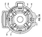
次に図7Aおよび7Bを参照すると、センサキャリッジ140の係合特徴が、伸張または係合状態(図7A)、格納または非係合状態(7B)で示される。例示的な実施形態では、センサキャリッジ140は、アーム146に関連付けられた、回転可能なリング147を含む。リング147は、アーム146を伸長状態と後退状態との間で移動させるように回転可能であり得る。例えば、アーム146およびリング147は、リング147がセンサキャリッジ140の他のコンポーネントに対して回転されるときに相互作用する、対応する特徴を含み得る。いくつかの例示的な実施形態では、アーム146およびリング147は、ラックアンドピニオンと同様に相互作用する対応する歯146a、147aを含む。リング147を第1の方向に回転させると、アーム146が伸長状態から後退状態に移動し、リング147を第2の方向に回転させると、アーム146が後退状態から伸張状態に移動する。このようにして、アーム146は、液体送達装置200と干渉しやすくなる係合状態(例えば、液体送達装置200の空洞111への挿入時)と、液体送達装置200との干渉を回避する後退状態(例えば、これによりセンサキャリッジ140がプランジャ検出動作中に液体送達装置200の一部に沿って移動可能となる)との間で移動可能である。 7A and 7B, the engagement features of sensor carriage 140 are shown in an extended or engaged state (FIG. 7A) and in a retracted or disengaged state (7B). In the exemplary embodiment, sensor carriage 140 includes a rotatable ring 147 associated with arm 146. Ring 147 may be rotatable to move arm 146 between an extended state and a retracted state. For example, arm 146 and ring 147 may include corresponding features that interact when ring 147 is rotated relative to other components of sensor carriage 140. In some exemplary embodiments, arm 146 and ring 147 include corresponding teeth 146a, 147a that interact similar to a rack and pinion. Rotating ring 147 in a first direction moves arm 146 from an extended state to a retracted state, and rotating ring 147 in a second direction moves arm 146 from a retracted state to an extended state. In this manner, the arm 146 can be placed in an engaged state in which it is susceptible to interference with the liquid delivery device 200 (e.g., upon insertion of the liquid delivery device 200 into the cavity 111), and in a retracted state in which it avoids interference with the liquid delivery device 200. (eg, allows sensor carriage 140 to move along a portion of liquid delivery device 200 during plunger sensing operations).

キャップ装置100は、センサキャリッジ140が第1および第2の位置に到達したときに、アーム146をそれぞれ伸長位置と後退位置との間で移動させる特徴を含み得る。例えば、いくつかの実施形態では、アーム146は、液体送達装置200の空洞111への挿入後に追加の手動操作なしに、伸長位置と後退位置との間を移動するように構成される。本体110は、傾斜またはスロープ表面を有する凹部115を含み得る。リング147は、凹部115の傾斜面と係合可能な突起147bを含む。突起147bが傾斜面に遭遇すると(例えば、液体送達装置200を空洞111に挿入する力による)、リング147は、センサキャリッジ140の他の部分に対して第1の方向に回転させられる。これにより、アーム146は、図7Bに示される後退位置に移動される。アーム146の後退位置への移動(例えば、キャップ装置100が液体送達装置200に係合し、センサキャリッジ140が前壁112に近接する第1の位置にあるとき)は、バネ160がセンサキャリッジ140を液体送達装置200に沿って、第1の位置から第2の位置に移動させるようにセンサキャリッジ140を解放し得る。あるいは/さらに、バネ、バネアームなどとの相互作用も、回転および/または移動発生に一部寄与し得る。 Cap device 100 may include a feature that moves arm 146 between an extended position and a retracted position when sensor carriage 140 reaches the first and second positions, respectively. For example, in some embodiments, arm 146 is configured to move between extended and retracted positions without additional manual manipulation after insertion of liquid delivery device 200 into cavity 111. Body 110 may include a recess 115 having an inclined or sloped surface. Ring 147 includes a protrusion 147b that can engage with the inclined surface of recess 115. When protrusion 147b encounters the inclined surface (eg, due to the force of inserting liquid delivery device 200 into cavity 111), ring 147 is rotated in the first direction relative to the rest of sensor carriage 140. This moves arm 146 to the retracted position shown in FIG. 7B. Movement of arm 146 to a retracted position (e.g., when cap device 100 engages liquid delivery device 200 and sensor carriage 140 is in a first position proximate front wall 112) causes spring 160 to Sensor carriage 140 may be released to move along liquid delivery device 200 from a first position to a second position. Alternatively/in addition, interactions with springs, spring arms, etc. may also contribute in part to rotation and/or movement generation.

トラック150のスロット151は、幅広端部領域152を含み得る(図3)。これは、伸長位置と後退位置との間のアーム146の移動を容易にするか、促す。例えば、幅広端部領域は、アーム146の回転のために追加の間隙を提供し得る。あるいは/さらに、幅広端部領域152は、アーム146を係合状態と後退状態との間で移動させる、センサキャリッジ140と係合可能なスロープ面または他の特徴を含み得る。スロット151は、センサキャリッジ140が第1の位置と第2の位置との間を移動する間、アーム146の回転または解放を防止または制限するように構成され得る。 Slot 151 of track 150 may include a wide end region 152 (FIG. 3). This facilitates or encourages movement of arm 146 between the extended and retracted positions. For example, the wide end region may provide additional clearance for rotation of arm 146. Alternatively/in addition, wide end region 152 may include a sloped surface or other feature engageable with sensor carriage 140 to move arm 146 between an engaged state and a retracted state. Slot 151 may be configured to prevent or limit rotation or release of arm 146 while sensor carriage 140 moves between the first and second positions.

いくつかの例示的な実施形態では、本体110は、センサキャリッジ140が開口部114に近接する第2の位置に到達する(例えば、バネ160により生じた動きで第2の位置に到達する)と、リング147をセンサキャリッジ140の他の部分に対して第2の方向に回転させる1つまたは複数の特徴を含み得る。次に図8を参照すると、キャップ装置100は、センサキャリッジ140が第2の位置にある時にリング147と相互作用するバネ117を含み得るバネ117は、リング147を第2の方向に回転させ、それによりアーム146を伸張状態に戻すように付勢されている。空洞111内の液体送達装置200の存在は、アーム146が伸長位置に移動するのを防ぐ。したがってリング147は、液体送達装置200が取り外される際にのみ、バネ117によって強制的に回転させられ得る。 In some exemplary embodiments, body 110 is configured such that when sensor carriage 140 reaches a second position proximate opening 114 (e.g., reaches the second position with movement caused by spring 160). , may include one or more features that rotate ring 147 in a second direction relative to the rest of sensor carriage 140. Referring now to FIG. 8, the cap device 100 may include a spring 117 that interacts with the ring 147 when the sensor carriage 140 is in the second position, causing the spring 117 to rotate the ring 147 in a second direction; This biases arm 146 back into its extended state. The presence of liquid delivery device 200 within cavity 111 prevents arm 146 from moving to the extended position. Ring 147 can therefore only be forced to rotate by spring 117 when liquid delivery device 200 is removed.

例示的な実施形態では、リング147の回転および/または伸長位置と後退位置との間のアーム146などの係合特徴の移動は、液体送達装置200の挿入および取り外し後の手動操作なしで生じ得る。例えば、液体送達装置200の挿入により、センサキャリッジ140が第1の位置に移動し、その後解放されることで、第1の位置から第2の位置に移動しながら液体送達装置200を走査する。空洞111から液体送達装置200が取り外されると、アーム146が伸張位置に戻る。これにより、キャップ装置100が再び液体送達装置200を受け入れ可能となる。したがって、様々な例示的な実施形態では、キャップ装置100は、液体送達装置200を繰り返しかつ確実に走査するように構成される。これにより、プランジャ205の位置が判定され、その後のプランジャ位置が評価されて、液体送達装置200の様々な特性およびその使用が判定される。 In exemplary embodiments, rotation of ring 147 and/or movement of engagement features such as arms 146 between extended and retracted positions may occur without manual intervention after insertion and removal of liquid delivery device 200. . For example, insertion of liquid delivery device 200 causes sensor carriage 140 to move to a first position and then released to scan liquid delivery device 200 while moving from the first position to a second position. When liquid delivery device 200 is removed from cavity 111, arm 146 returns to the extended position. This allows the cap device 100 to accept the liquid delivery device 200 again. Accordingly, in various exemplary embodiments, cap device 100 is configured to repeatedly and reliably scan liquid delivery device 200. This determines the position of plunger 205 and evaluates subsequent plunger positions to determine various characteristics of liquid delivery device 200 and its use.

次に図9Aおよび9Bを参照すると、例示的液体送達装置200の部分斜視図と、断面図が示されている。液体送達装置200は、センサ142などのセンサのセンサ信号に影響し得る様々な特徴を含む。例えば、液体送達装置200は、比較的高い不透明度を有する領域208、リブ209、しるし210、および/またはセンサ142によって利用される放射エネルギーの透過率を比較的低くできる他の特徴、ならびに比較的低い不透明度を有する領域212を含み得る。これら特徴は、障害物となる可能性があり、さらに/あるいはプランジャ205との遭遇時に生成されるセンサ信号と同様のセンサ信号、または正確な測定に使用できないその他信号に帰結し得る。同様に、プランジャ205は、その先端面に隆起または突起211を含み得る。 9A and 9B, a partial perspective view and a cross-sectional view of an exemplary liquid delivery device 200 are shown. Liquid delivery device 200 includes various features that can affect the sensor signal of a sensor, such as sensor 142. For example, liquid delivery device 200 may include regions 208 having relatively high opacity, ribs 209, indicia 210, and/or other features that may have relatively low transmission of radiant energy utilized by sensor 142, as well as relatively high opacity. It may include regions 212 with low opacity. These features may result in obstructions and/or sensor signals similar to those generated upon encounter with plunger 205, or other signals that cannot be used for accurate measurements. Similarly, plunger 205 may include a ridge or protrusion 211 on its distal surface.

各種例示的な実施形態では、これら特徴は、キャップ装置100および液体送達装置200の所定の角度配向によって回避および/または考慮することができる。図9Bに示すように、液体送達装置200は、比較的低い不透明度を有する領域212を通る経路(C)、(D)を含む。あるいは/さらに、経路(C)、(D)は、より高い不透明度を有する領域208、リブ209、および/またはしるし210のうちの1つまたは複数との交差を回避する。例示的な実施形態では、キャップ装置100は、当該特徴との交差を回避するために、センサ142の光路142cなどの少なくとも1つのセンサのセンサ経路が、経路(C)または(D)と同様に位置合わせされるように液体送達装置200を配向するように構成され得る。例えば、互いにずれた2つのセンサ142、143を有するセンサキャリッジ140(例えば、図4に示される構成)は、領域212を通る少なくとも1つのセンサ経路の位置合わせを容易にする。センサ142、143によって出力されたセンサ信号は、プランジャ205を液体送達装置200の他の1つまたは複数の特徴から確実に区別するように処理することができる。あるいは/さらに、センサ142、143によって出力されたセンサ信号は、隆起または突起211の存在を考慮するために処理され得る(例えば、センサ142、143のそれぞれからの一連のセンサ信号を評価することによる)。したがって、プランジャ205の信頼性が高く、繰り返し可能な検出は、液体送達装置200の他の1つまたは複数の特徴を考慮すること、および/または動作中に液体送達装置200をキャップ装置100に対して固定された長手方向および角度位置に維持することによって実現され得る。 In various exemplary embodiments, these features may be avoided and/or accounted for by predetermined angular orientations of cap device 100 and liquid delivery device 200. As shown in FIG. 9B, liquid delivery device 200 includes paths (C), (D) through regions 212 having relatively low opacity. Alternatively/in addition, paths (C), (D) avoid intersecting one or more of regions 208, ribs 209, and/or indicia 210 with higher opacity. In an exemplary embodiment, the capping device 100 is arranged such that the sensor path of at least one sensor, such as the optical path 142c of the sensor 142, is similar to path (C) or (D) to avoid intersection with the feature. The liquid delivery device 200 may be configured to orient the liquid delivery device 200 so that it is aligned. For example, a sensor carriage 140 having two sensors 142, 143 offset from each other (eg, the configuration shown in FIG. 4) facilitates alignment of at least one sensor path through region 212. The sensor signals output by sensors 142 , 143 can be processed to reliably distinguish plunger 205 from one or more other features of liquid delivery device 200 . Alternatively/in addition, the sensor signals output by the sensors 142, 143 may be processed to account for the presence of a bump or protrusion 211 (e.g., by evaluating a series of sensor signals from each of the sensors 142, 143). ). Accordingly, reliable and repeatable detection of plunger 205 can be achieved by taking into account one or more other characteristics of liquid delivery device 200 and/or by moving liquid delivery device 200 relative to capping device 100 during operation. This can be achieved by maintaining the device in a fixed longitudinal and angular position.

次に図10および11を参照すると、液体の貯蔵および送達に使用可能な例示的液体送達システム50が示される液体送達システム50は、キャップ装置700および液体送達装置900を含む。液体送達装置900は、リザーバ901、送達端902、および送達端902を通してリザーバ901内の液体の用量を送達するように操作され得るプランジャ905を含む。キャップ装置700は、液体送達装置900の使用と使用の間の保管のために、液体送達装置900の送達端902上に配置可能である。例示的な実施形態では、キャップ装置700は、液体送達装置900の状態の状態(そのプランジャの位置など)を検出するように構成された1つまたは複数のセンサと、液体送達装置900の状態に関連する情報を出力するように構成され得る1つまたは複数の出力デバイス(ディスプレイ、通信システムなど)とを含む。いくつかの例示的な実施形態では、液体送達システム50は、図1から図9を参照して上記で説明した液体送達システム10の特徴および特性と同様の特徴および特性を含む。 10 and 11, an exemplary liquid delivery system 50 that can be used to store and deliver liquids is shown. Liquid delivery system 50 includes a cap device 700 and a liquid delivery device 900. Liquid delivery device 900 includes a reservoir 901 , a delivery end 902 , and a plunger 905 that can be operated to deliver a dose of liquid within reservoir 901 through delivery end 902 . Cap device 700 is positionable on delivery end 902 of liquid delivery device 900 for storage between uses of liquid delivery device 900. In an exemplary embodiment, the cap device 700 includes one or more sensors configured to detect a condition of the liquid delivery device 900 (such as the position of its plunger) and a sensor configured to detect the condition of the liquid delivery device 900 . one or more output devices (displays, communication systems, etc.) that may be configured to output relevant information. In some exemplary embodiments, liquid delivery system 50 includes features and characteristics similar to those of liquid delivery system 10 described above with reference to FIGS. 1-9.

キャップ装置700は、液体送達装置900の状態を検出するように構成された1つまたは複数のセンサを含み得る。例示的な実施形態では、キャップ装置700は、プランジャ、プランジャの位置、キャップ装置700との一連の係合と係合の間のプランジャの位置の変化(例えば、容量送達後の位置の変化)、および/または液体送達装置900のその他の状態を検出するように評価され得るセンサ信号を出力するセンサを含む。プランジャの位置、および/またはプランジャの位置の変化は、液体送達装置900によって送達される投薬量、リザーバ902内の液体の残りの総量、リザーバ902内の残りの投薬回数数、リザーバ902が空になるまでの残り時間、および/または液体送達装置900に関連する他の情報を監視するために使用され得る。 Cap device 700 may include one or more sensors configured to detect the condition of liquid delivery device 900. In an exemplary embodiment, the cap device 700 includes a plunger, a position of the plunger, a change in position of the plunger between successive engagements with the cap device 700 (e.g., a change in position after volume delivery); and/or sensors that output sensor signals that can be evaluated to detect other conditions of the liquid delivery device 900. The position of the plunger and/or the change in the position of the plunger determines the amount of dosage delivered by the liquid delivery device 900, the total amount of liquid remaining in the reservoir 902, the number of doses remaining in the reservoir 902, the amount of medication remaining in the reservoir 902, and the amount of medication remaining in the reservoir 902. The liquid delivery device 900 may be used to monitor the amount of time remaining and/or other information related to the liquid delivery device 900.

いくつかの実施形態では、キャップ装置700は、本体710内で移動可能である(例えば、本体710の壁と液体送達装置が配置される内腔748との間で、空洞711内で移動可能)センサキャリッジ740を含む。センサキャリッジ740は、空洞711内の液体送達装置900の少なくとも一部に沿って移動するように構成され、空洞711は、液体送達装置900の寸法およびセンサキャリッジ740の経路を収容するようなサイズに設定される。センサキャリッジ740は、第1の位置と第2の位置との間で液体送達装置に沿って1つまたは複数のセンサを運ぶことによって、液体送達装置900の特性の検出を容易にする。センサキャリッジ740は、液体送達装置900が空洞711に対して固定位置に留まっている状態で、空洞711に対して第1の位置と第2の位置との間で移動可能である(例えば、センサキャリッジ740は、液体送達装置900がキャップ装置700と固定的に係合している状態で移動可能である)。 In some embodiments, the cap device 700 is movable within the body 710 (e.g., movable within the cavity 711 between the wall of the body 710 and the lumen 748 in which the liquid delivery device is disposed). A sensor carriage 740 is included. Sensor carriage 740 is configured to move along at least a portion of liquid delivery device 900 within cavity 711 , cavity 711 is sized to accommodate the dimensions of liquid delivery device 900 and the path of sensor carriage 740 . Set. Sensor carriage 740 facilitates detection of characteristics of liquid delivery device 900 by carrying one or more sensors along the liquid delivery device between a first position and a second position. The sensor carriage 740 is movable between a first position and a second position relative to the cavity 711 with the liquid delivery device 900 remaining in a fixed position relative to the cavity 711 (e.g., Carriage 740 is movable with liquid delivery device 900 fixedly engaged with capping device 700).

例示的な実施形態では、キャップ装置700は、センサキャリッジ740を第1の位置から第2の位置に移動させるように構成されたバネ760を含む。例えば、バネ760は、液体送達装置900を空洞711に挿入することなどによって、センサキャリッジ740を本体710の前壁712に近接する第1の位置に移動するように手動で圧縮され得、解放時にセンサキャリッジを本体710の開口部714に近接する第2の位置に戻すように付勢され得る。 In the exemplary embodiment, cap device 700 includes a spring 760 configured to move sensor carriage 740 from a first position to a second position. For example, spring 760 may be manually compressed to move sensor carriage 740 to a first position proximate front wall 712 of body 710, such as by inserting liquid delivery device 900 into cavity 711, and upon release, The sensor carriage may be biased back to a second position proximate opening 714 of body 710.

センサキャリッジ740は、センサキャリッジが第1の位置と第2の位置との間を移動する際に、液体送達装置900の状態を検出するように構成された1つまたは複数のセンサコンポーネントを含む。様々な例示的な実施形態では、センサキャリッジ740は、液体送達装置900の状態を評価するために使用可能な情報を検出するように構成されたプランジャセンサのコンポーネントを含む。あるいは、センサキャリッジ740は、位置センサのコンポーネントのみを含み得る(例えば、プランジャセンサを含まない)。いくつかの実施形態では、1つまたは複数の光学センサ744は、キャップ装置700の本体710上に固定的に配置され得る。 Sensor carriage 740 includes one or more sensor components configured to detect a condition of liquid delivery device 900 as sensor carriage moves between a first position and a second position. In various exemplary embodiments, sensor carriage 740 includes a plunger sensor component configured to detect information that can be used to assess the condition of liquid delivery device 900. Alternatively, sensor carriage 740 may include only position sensor components (eg, no plunger sensor). In some embodiments, one or more optical sensors 744 may be fixedly disposed on the body 710 of the cap device 700.

次に図10Aから10Dを参照すると、センサキャリッジ740は、液体送達装置900と相互作用するように構成された1つまたは複数の係合特徴を含む。例えば、センサキャリッジ740は、液体送達装置900によって押されると、センサキャリッジ740を動かすことができるアーム746を含む。液体送達装置900が空洞711に挿入されると、アーム746と液体送達装置900との間の干渉により、センサキャリッジ740が液体送達装置900と共に本体710の前壁712に向かって移動する。アーム746は、その後、液体送達装置900から係合解除されて、センサキャリッジ740を解放する。したがって、液体送達装置900がキャップ装置700の空洞711に対して固定位置に留まっている状態で、センサキャリッジ740は空洞711の開口部714に向かって戻る。例えば、アーム746は、センサキャリッジ740および/またはキャップ700の他の1つまたは複数のコンポーネントとの相互作用によって、係合状態と非係合状態との間で移動可能であり得る可撓性アームであり得る。いくつかの実施形態では、バネ760は、液体送達装置900が空洞711(例えば内腔748)に完全に挿入されると圧縮され得、アーム746が液体送達装置900との係合から解放されると、センサキャリッジ740を開口部714に向けて戻し得る。 Referring now to FIGS. 10A-10D, sensor carriage 740 includes one or more engagement features configured to interact with liquid delivery device 900. For example, sensor carriage 740 includes an arm 746 that can move sensor carriage 740 when pushed by liquid delivery device 900. When the liquid delivery device 900 is inserted into the cavity 711, the interference between the arm 746 and the liquid delivery device 900 causes the sensor carriage 740 to move with the liquid delivery device 900 toward the front wall 712 of the body 710. Arm 746 is then disengaged from liquid delivery device 900 to release sensor carriage 740. Thus, the sensor carriage 740 moves back toward the opening 714 of the cavity 711 with the liquid delivery device 900 remaining in a fixed position relative to the cavity 711 of the cap device 700. For example, arm 746 is a flexible arm that may be movable between an engaged state and a disengaged state by interaction with sensor carriage 740 and/or one or more other components of cap 700. It can be. In some embodiments, spring 760 may be compressed when liquid delivery device 900 is fully inserted into cavity 711 (e.g., lumen 748), and arm 746 is released from engagement with liquid delivery device 900. The sensor carriage 740 may then be moved back towards the opening 714.

例示的な実施形態では、センサキャリッジ740は、センサキャリッジ740の外周の周りに間隔を置いて配置された2つのアーム746を含む。アーム746は、アーム746がセンサキャリッジ740によって画定される内腔748内へと延在する伸長位置(例えば、センサキャリッジ740の内壁から内側に延びる)と後退位置との間で移動可能である。アーム746は、カム表面749bを含むセンサキャリッジリング749aなどの、センサキャリッジ740の1つまたは複数のコンポーネントに対して移動可能であり得る。第1の相対位置(図10A、10B)では、アーム746は、カム表面749bによって屈曲または係合状態に維持される。アーム746は、内腔748内に延在し、キャップ装置700に挿入された液体送達装置と干渉するように配置されている。第2の相対位置(図10C、10D)では、アーム746は、カム表面749bと接触しておらず、非屈曲または非係合状態にある(例えば、アーム746は、カム表面749bによって強制的に係合位置に配置されていない)。アーム746は、センサキャリッジ740が、移動を妨げる干渉なしに、内腔748および/または内腔748内に配置された液体送達装置900に対して移動できるように配置される。 In the exemplary embodiment, sensor carriage 740 includes two arms 746 spaced around the circumference of sensor carriage 740 . Arm 746 is movable between an extended position in which arm 746 extends into a lumen 748 defined by sensor carriage 740 (eg, extending inwardly from an inner wall of sensor carriage 740) and a retracted position. Arm 746 may be movable relative to one or more components of sensor carriage 740, such as sensor carriage ring 749a that includes camming surface 749b. In the first relative position (FIGS. 10A, 10B), arm 746 is maintained flexed or engaged by camming surface 749b. Arm 746 extends into lumen 748 and is positioned to interfere with a liquid delivery device inserted into cap device 700. In a second relative position (FIGS. 10C, 10D), arm 746 is not in contact with cam surface 749b and is in an unflexed or disengaged state (e.g., arm 746 is forced by cam surface 749b to (not placed in the engaged position). Arm 746 is positioned such that sensor carriage 740 can move relative to lumen 748 and/or liquid delivery device 900 disposed within lumen 748 without interference preventing movement.

アーム746とカム表面749bとの間の相対移動は、センサキャリッジ740とキャップ装置700の1つまたは複数の特徴との間の相互作用により生じ得る。例えば、本体710は、液体送達装置900の挿入中にセンサキャリッジリング749aのさらなる長手方向の動きを防止する1つまたは複数のリブ718を含み得る。アーム746は継続的に移動することで、表面749bとの接触から解放され得る。その結果、アームは屈曲し、退避または非係合状態になることができる(図10C、10D)。センサキャリッジ740が開口部714に近接する位置に戻されると(例えば、バネ760によって)、リブ719は、バネ760がアーム746を押し続けている間、センサキャリッジリング749aのさらなる長手方向の動きを防ぐことができる。したがって、アーム746は、カム表面749bと強制的に接触させられ、伸張状態または係合状態に移動され得る。 Relative movement between arm 746 and camming surface 749b may occur due to interaction between sensor carriage 740 and one or more features of capping device 700. For example, body 710 may include one or more ribs 718 that prevent further longitudinal movement of sensor carriage ring 749a during insertion of liquid delivery device 900. Arm 746 may continue to move out of contact with surface 749b. As a result, the arms can flex and become retracted or disengaged (FIGS. 10C, 10D). When sensor carriage 740 is returned to a position proximate opening 714 (e.g., by spring 760), rib 719 prevents further longitudinal movement of sensor carriage ring 749a while spring 760 continues to push arm 746. It can be prevented. Thus, arm 746 can be forced into contact with cam surface 749b and moved into an extended or engaged state.

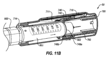
図11AからFを参照すると、キャップ装置700は、本体710の開口部714を介して空洞711内に送達端902を挿入することにより、液体送達装置900と係合可能である。液体送達装置900が開口部714(図11A)を通じて挿入されると、送達端902は、伸長位置にあるアーム746などのセンサキャリッジ740の係合特徴に遭遇する。キャップ装置700と液体送達装置900との間の相対移動(例えば、キャップ装置700と液体送達装置900が一体となる)により、液体送達装置900がセンサキャリッジ740を空洞711に押し込む(図11B)。センサキャリッジ740が本体710の前壁712に近接する位置に到達すると、例えば、センサキャリッジリング749aの長手方向の動きは、リブ718によって停止され、アーム746は、センサキャリッジリング749aに対して(例えば、液体送達装置900の挿入による力によって)移動し得る。そのような相対移動により、アーム746がカム表面749bとの接触から解放され、非係合状態に移動する(図11C)。アーム746が非係合状態に移動すると、アーム746およびセンサキャリッジ740が液体送達装置900と干渉しなくなるように移動する。したがって、センサキャリッジがバネ760によって(例えば、開口部714に向かって)移動され得る(図11D)。センサキャリッジ740が本体710の開口部714に近接する位置に到達すると、例えば、センサキャリッジリング749aの長手方向の動きは、リブ719によって停止され、アーム746は、センサキャリッジリング749aに対して(例えば、バネ760からの力によって)移動し得る(図11E)。そのような相対移動により、アーム746がカム表面749bと接触し、屈曲または係合状態に移動する(図11F)。センサキャリッジ740が開口部714の近くに配置され、アーム746が係合状態にあると、液体送達装置900が再度収容され得、処理が繰り返され得る。 Referring to FIGS. 11A-F, cap device 700 is engageable with liquid delivery device 900 by inserting delivery end 902 into cavity 711 through opening 714 in body 710. When liquid delivery device 900 is inserted through opening 714 (FIG. 11A), delivery end 902 encounters engagement features of sensor carriage 740, such as arm 746, in an extended position. Relative movement between cap device 700 and liquid delivery device 900 (eg, cap device 700 and liquid delivery device 900 come together) causes liquid delivery device 900 to force sensor carriage 740 into cavity 711 (FIG. 11B). When the sensor carriage 740 reaches a position proximate the front wall 712 of the body 710, e.g. , by force due to insertion of the liquid delivery device 900). Such relative movement releases arm 746 from contact with cam surface 749b and moves it into a disengaged state (FIG. 11C). When arm 746 moves into the disengaged state, arm 746 and sensor carriage 740 move out of interference with liquid delivery device 900 . Accordingly, the sensor carriage may be moved (eg, toward opening 714) by spring 760 (FIG. 11D). When the sensor carriage 740 reaches a position proximate the opening 714 of the body 710, for example, the longitudinal movement of the sensor carriage ring 749a is stopped by the rib 719, and the arm 746 is , by force from spring 760) (FIG. 11E). Such relative movement causes arm 746 to contact cam surface 749b and move into flexion or engagement (FIG. 11F). With sensor carriage 740 positioned near opening 714 and arm 746 in engagement, liquid delivery device 900 may be re-stored and the process repeated.

図12を参照すると、液体を貯蔵および送達するために使用することができる例示的な液体送達システム20が示されている。液体送達システム20は、キャップ装置300および液体送達装置400を含む。液体送達装置400は、リザーバ401、送達端402、および送達端402を通してリザーバ401内の液体の投薬量を送達するように操作され得るプランジャ405を含む。キャップ装置300は、液体送達装置400の使用間の保管のために、液体送達装置400の送達端402上に配置可能である。例示的な実施形態では、キャップ装置300は、リニアエンコーダを含む1つまたは複数のセンサを含む。キャップ装置は、液体送達装置400の状態(そのプランジャの位置など)を検出するように構成された1つまたは複数のセンサと、液体送達装置400の状態に関連する情報を出力するように構成された1つまたは複数の出力デバイス(ディスプレイ、通信システムなど)とを含む。いくつかの例示的な実施形態では、液体送達システム20は、図1から図11を参照して上記で説明した液体送達システム10の特徴および特性と同様の特徴および特性を含む。 Referring to FIG. 12, an exemplary liquid delivery system 20 that can be used to store and deliver liquids is shown. Liquid delivery system 20 includes a cap device 300 and a liquid delivery device 400. Liquid delivery device 400 includes a reservoir 401 , a delivery end 402 , and a plunger 405 that can be operated to deliver a dosage of the liquid in reservoir 401 through delivery end 402 . Cap device 300 is positionable on delivery end 402 of liquid delivery device 400 for storage between uses of liquid delivery device 400. In an exemplary embodiment, cap device 300 includes one or more sensors including a linear encoder. The cap device includes one or more sensors configured to detect a condition of the liquid delivery device 400 (such as the position of its plunger) and configured to output information related to the condition of the liquid delivery device 400. and one or more output devices (displays, communication systems, etc.). In some exemplary embodiments, liquid delivery system 20 includes features and characteristics similar to those of liquid delivery system 10 described above with reference to FIGS. 1-11.

液体送達装置400は、疾患の治療のために、測定された投薬量の液体を対象に送達するように構成され得る。例えば、液体送達装置400は、糖尿病を管理するために、インスリンなどの液体を送達するためのペン注射器であり得る。例示的な実施形態では、液体送達装置400の送達端402は、隔壁403および注射針404を含む。所望の投薬量は、ダイヤル406の操作(例えば、ダイヤル406を手動で回転させることによる)、およびプランジャを前進させるための液体送達装置400の操作によって測定され得る。ロッド414を介したプランジャ405の前進により、測定された投薬量の液体がリザーバ401から送達端402を通じて対象に押し込まれる。例示的な実施形態では、プランジャ405を特定の距離だけ前進させると、対応する量の液体が液体送達装置400から分注される。 Liquid delivery device 400 may be configured to deliver a measured dose of liquid to a subject for treatment of a disease. For example, fluid delivery device 400 may be a pen syringe for delivering fluids such as insulin to manage diabetes. In the exemplary embodiment, delivery end 402 of liquid delivery device 400 includes a septum 403 and a needle 404. The desired dosage can be measured by manipulation of dial 406 (eg, by manually rotating dial 406) and manipulation of liquid delivery device 400 to advance the plunger. Advancement of plunger 405 through rod 414 forces a measured dose of liquid from reservoir 401 through delivery end 402 and into the subject. In the exemplary embodiment, advancing plunger 405 a particular distance causes a corresponding amount of liquid to be dispensed from liquid delivery device 400.

キャップ装置300は、液体送達装置400の状態を検出するように構成された1つまたは複数のセンサを含み得る。例示的な実施形態では、キャップ装置300は、プランジャ、プランジャの位置、キャップ装置300との一連の係合と係合の間のプランジャの位置の変化(例えば、容量送達後の位置の変化)、および/または液体送達装置400のその他の状態を検出するように評価され得るセンサ信号を出力するセンサを含む。プランジャの位置、および/またはプランジャの位置の変化は、液体送達装置400によって送達される投薬量、リザーバ402内の液体の残りの総量、リザーバ402内の残りの投薬回数、リザーバ402が空になるまでの残り時間、および/または液体送達装置400に関連するその他情報を監視するために使用され得る。 Cap device 300 may include one or more sensors configured to detect the condition of liquid delivery device 400. In an exemplary embodiment, the cap device 300 includes a plunger, a position of the plunger, a change in position of the plunger between successive engagements with the cap device 300 (e.g., a change in position after volume delivery); and/or a sensor that outputs a sensor signal that can be evaluated to detect other conditions of the liquid delivery device 400. The position of the plunger and/or the change in the position of the plunger determines the amount of dosage delivered by the liquid delivery device 400, the total amount of liquid remaining in the reservoir 402, the number of doses remaining in the reservoir 402, the number of doses remaining in the reservoir 402, the amount of dosage delivered by the fluid delivery device 400, the number of doses remaining in the reservoir 402, and the amount of dosage delivered by the liquid delivery device 400. may be used to monitor the time remaining and/or other information related to the liquid delivery device 400.

キャップ装置300は、任意で、キャップ装置100とのユーザ相互作用を容易にする1つまたは複数のユーザ入力322を含む。例示的な実施形態では、ユーザ入力322は、キャップ装置300を制御するために操作され得る第1および第2のボタンを含む。例えば、ユーザ入力322は、キャップ装置300を起動するために、さらに/あるいはディスプレイ321によって表示される情報を選択するために、ユーザによって操作され得る。あるいは/さらに、ユーザ入力322は、キャップ装置300が新しい液体送達装置400と係合しているときなど、キャップ装置300の設定および/またはメモリをリセットするように操作され得る。いくつかの例示的な実施形態では、キャップ装置300は、手動で操作可能なユーザ入力を含まない。ボタンまたは他のユーザ入力を含まないキャップ装置300は、操作性を改善し、完全に自動化されたキャップ装置300の認知を促進し得る。 Cap device 300 optionally includes one or more user inputs 322 to facilitate user interaction with cap device 100. In the exemplary embodiment, user input 322 includes first and second buttons that may be operated to control cap device 300. For example, user input 322 may be manipulated by a user to activate capping device 300 and/or to select information displayed by display 321. Alternatively/in addition, user input 322 may be manipulated to reset settings and/or memory of cap device 300, such as when cap device 300 is engaged with a new liquid delivery device 400. In some exemplary embodiments, capping device 300 does not include manually operable user input. A cap device 300 that does not include buttons or other user input may improve operability and facilitate the perception of a fully automated cap device 300.

キャップ装置300は、液体送達システムの他の1つまたは複数のコンポーネントと通信して、キャップ装置100および/または液体送達装置400の状態に関連する情報を送信および/または受信することができる。例えば、キャップ装置300は、キャップ装置300から離れた1つまたは複数のコンポーネントと通信するように構成された通信デバイス323を含む。通信デバイス323は、短波長UHF無線周波数、RF通信、WI-FI、BLUETOOTH、ZIGBEEを介したもののような無線通信用に構成された無線通信プリント回路アセンブリを含み得る。あるいは/さらに、通信デバイス323は、電気別の電子機器との有線通信用のポートを含み得る。様々な例示的な実施形態では、通信デバイス323は、キャップ装置300との通信を送受信するように構成されたソフトウェアを有するモバイルデバイスとの双方向通信などの双方向通信用に構成される。あるいは、キャップ装置300は、情報のモバイルデバイスへのアップロード専用、またはモバイルデバイスからの情報受信専用などのように、一方向通信用に構成され得る。 Cap device 300 can communicate with one or more other components of the liquid delivery system to send and/or receive information related to the status of cap device 100 and/or liquid delivery device 400. For example, cap apparatus 300 includes a communication device 323 configured to communicate with one or more components remote from cap apparatus 300. Communication device 323 may include a wireless communication printed circuit assembly configured for wireless communication, such as via short wavelength UHF radio frequencies, RF communications, WI-FI, BLUETOOTH, ZIGBEE. Alternatively/in addition, communication device 323 may include a port for wired communication with other electronic equipment. In various exemplary embodiments, communication device 323 is configured for two-way communication, such as two-way communication with a mobile device having software configured to send and receive communications with cap device 300. Alternatively, capping device 300 may be configured for one-way communication, such as only for uploading information to or receiving information from a mobile device.

通信デバイス323は、糖尿病管理ソフトウェアで構成された電子装置と通信するように構成され得る。例えば、通信デバイス323は、電子デバイスによってさらに処理され得る液体送達装置400に関連する情報を送信し得る。このようにして、キャップ装置300は、そのセンサによって収集された情報を、離れた場所のユーザまたはヘルスケアプロバイダーによって遠隔評価しやすくし、電子デバイスによる液体送達システム400に関連するアラートを提供し得(例えば、注射の予定時間、液体送達装置がほぼ空であるなど)、さらに/あるいはキャップ装置300によって収集された情報の追加の処理および分析を容易にする。 Communication device 323 may be configured to communicate with an electronic device configured with diabetes management software. For example, communication device 323 may transmit information related to liquid delivery apparatus 400 that may be further processed by an electronic device. In this manner, the cap apparatus 300 may facilitate remote evaluation of information collected by its sensors by a remote user or healthcare provider and provide alerts related to the electronic device liquid delivery system 400. (e.g., scheduled time of injection, liquid delivery device nearly empty, etc.) and/or facilitates further processing and analysis of information collected by capping device 300.

いくつかの任意の実施形態では、キャップ装置300は任意で、本体310内で移動可能である(例えば、空洞311内で移動可能である)センサキャリッジ340を含む。センサキャリッジ340は、空洞311内の液体送達装置400の少なくとも一部に沿って移動するように構成され、空洞311は、液体送達装置400の寸法およびセンサキャリッジ340の経路を収容するようなサイズに設定される。センサキャリッジ340は、第1の位置と第2の位置との間で液体送達装置に沿って1つまたは複数のセンサを運ぶことによって、液体送達装置400の特性の検出を容易にする。センサキャリッジ340は、液体送達装置400が空洞311に対して固定位置に留まっている状態で、任意で空洞311に対して第1の位置と第2の位置との間で移動可能である(例えば、センサキャリッジ340は、液体送達装置400がキャップ装置300と固定的に係合している状態で移動可能である)。 In some optional embodiments, cap device 300 optionally includes a sensor carriage 340 that is movable within body 310 (eg, movable within cavity 311). Sensor carriage 340 is configured to move along at least a portion of liquid delivery device 400 within cavity 311 , cavity 311 is sized to accommodate the dimensions of liquid delivery device 400 and the path of sensor carriage 340 . Set. Sensor carriage 340 facilitates detection of characteristics of liquid delivery device 400 by carrying one or more sensors along the liquid delivery device between a first position and a second position. Sensor carriage 340 is optionally movable relative to cavity 311 between a first position and a second position, with liquid delivery device 400 remaining in a fixed position relative to cavity 311 (e.g. , the sensor carriage 340 is movable with the liquid delivery device 400 fixedly engaged with the capping device 300).

キャップ装置300は、トラック350を含み得る。センサキャリッジ340は、トラック350に沿って移動し得、トラック350は、センサキャリッジ340の動きを誘導および/または制限する1つまたは複数の特徴を含むことができる。例示的な実施形態では、キャップ装置300は、センサキャリッジ340を第1の位置から第2の位置に移動させるように構成されたバネ360を含む。例えば、バネ360は、液体送達装置400を空洞311に挿入することなどによって、センサキャリッジ340を本体310の前壁312に近接する第1の位置に移動するように手動で圧縮され得、解放時にセンサキャリッジを本体310の開口314に近接する第2の位置に戻すように付勢され得る。 Cap device 300 may include a track 350. Sensor carriage 340 may move along track 350, and track 350 may include one or more features that guide and/or limit movement of sensor carriage 340. In the exemplary embodiment, cap device 300 includes a spring 360 configured to move sensor carriage 340 from a first position to a second position. For example, spring 360 may be manually compressed to move sensor carriage 340 to a first position proximate front wall 312 of body 310, such as by inserting liquid delivery device 400 into cavity 311, and upon release, The sensor carriage may be biased back to a second position proximate the opening 314 of the body 310.

センサキャリッジ340は、センサキャリッジが第1の位置と第2の位置との間を移動する際に、液体送達装置400の状態を検出するように構成された1つまたは複数のセンサコンポーネントを含む。様々な例示的な実施形態では、センサキャリッジ340は、液体送達装置400の状態を評価するために使用可能な情報を検出するように構成されたプランジャセンサのコンポーネント(光学センサ、およびリニアエンコーダなどの位置センサ)を含む。あるいは、センサキャリッジ340は、位置センサのコンポーネントのみを含み得る(例えば、プランジャセンサを含まない)。いくつかの実施形態では、1つまたは複数の光学センサ344は、キャップ装置300の本体310上に固定的に配置され得る。 Sensor carriage 340 includes one or more sensor components configured to detect a condition of liquid delivery device 400 as sensor carriage moves between a first position and a second position. In various exemplary embodiments, sensor carriage 340 includes plunger sensor components (such as optical sensors and linear encoders) that are configured to detect information that can be used to assess the condition of liquid delivery device 400. position sensor). Alternatively, sensor carriage 340 may include only position sensor components (eg, no plunger sensor). In some embodiments, one or more optical sensors 344 may be fixedly disposed on the body 310 of the cap device 300.

いくつかの実施形態では、センサキャリッジ340は、光学エミッタ342aおよび光学エミッタ342bなどの、エミッタ342aおよびレシーバ342bを含むセンサ342(例えば、プランジャセンサ)を有する。光学エミッタ342aは、光学レシーバ342bによって検出することができる放射エネルギーを放出し、いくつかの実施形態では、LEDまたはレーザダイオードを含み得る。光学レシーバ342bは、光学エミッタ342aから受信した放射エネルギーに関連する信号を出力し得る。これは、光学エミッタ342aと光受信342bとの間の経路342cに存在する液体送達装置400の部位に依存し得る。したがって、光学レシーバによって受け取られる放射エネルギーの量は、経路342cがプランジャまたは他の固体構造と交差するときに比較的少なく、経路342cがリザーバの透明な壁およびその液体内容物と交差するときに比較的高くなり得る。 In some embodiments, sensor carriage 340 has a sensor 342 (eg, a plunger sensor) that includes an emitter 342a and a receiver 342b, such as optical emitter 342a and optical emitter 342b. Optical emitter 342a emits radiant energy that can be detected by optical receiver 342b, and in some embodiments may include an LED or a laser diode. Optical receiver 342b may output a signal related to the radiant energy received from optical emitter 342a. This may depend on the portion of the liquid delivery device 400 that is in the path 342c between the optical emitter 342a and the optical receiver 342b. Therefore, the amount of radiant energy received by the optical receiver is relatively low when path 342c intersects a plunger or other solid structure, compared to when path 342c intersects the transparent wall of the reservoir and its liquid contents. It can be highly targeted.

センサ342に代えて/加えて、センサキャリッジ340は、位置または距離を示すセンサ信号を出力するように構成された位置センサ345を含み得る。例示的な実施形態では、キャップ装置300は、センサキャリッジ340の位置および/またはセンサキャリッジ340が(例えば、センサキャリッジ340が液体送達装置400に沿って、または液体送達装置400による後続の投薬間に移動する際に)第1の位置と第2の位置との間で移動した距離を示すセンサ信号を出力する位置センサ345を含む。例示的な実施形態では、位置センサ345は、反射型リニアエンコーダまたは透過型リニアエンコーダなどのリニアエンコーダを含む。エンコーダコードストリップ345aは、本体310の側壁313またはトラック350など、空洞311の長さ方向の少なくとも一部に沿って配置されている。光学エンコーダなどのエンコーダ345bは、センサキャリッジ340上に配置されている。いくつかの例示的な実施形態では、エンコーダ345bは、コードストリップ345aに近接しながら接触せずに配置され得る。 Instead/in addition to sensor 342, sensor carriage 340 may include a position sensor 345 configured to output a sensor signal indicative of position or distance. In an exemplary embodiment, the capping device 300 is configured such that the position of the sensor carriage 340 and/or the sensor carriage 340 (e.g., when the sensor carriage 340 is along the liquid delivery device 400 or during subsequent dispensing by the liquid delivery device 400 a position sensor 345 that outputs a sensor signal indicative of the distance traveled between a first position and a second position (as the position is moved). In an exemplary embodiment, position sensor 345 includes a linear encoder, such as a reflective linear encoder or a transmissive linear encoder. Encoder code strip 345a is disposed along at least a portion of the length of cavity 311, such as sidewall 313 or track 350 of body 310. An encoder 345b, such as an optical encoder, is located on the sensor carriage 340. In some exemplary embodiments, encoder 345b may be placed in close proximity to but not in contact with code strip 345a.

リニアエンコーダ345は、コードストリップ345aに沿ったエンコーダ345bの位置(例えば、空洞311に沿ったセンサキャリッジ340の位置)に応じて変化するセンサ信号(例えば、カウント)を出力し得る様々な例示的な実施形態では、コードストリップ345aは、一連の交互の暗線および白線などの光学パターンを含む。リニアエンコーダ345は、コードストリップ345aに沿ったエンコーダ345bの位置を示すセンサ信号を出力し得る。例えば、特定のカウントは、コードストリップ345aに沿った特定の位置に関連付けられ得、カウントは、エンコーダ345bのコードストリップ345aに沿った移動毎に一定で、再現可能であり得る。 Linear encoder 345 may output a sensor signal (e.g., a count) that varies depending on the position of encoder 345b along code strip 345a (e.g., the position of sensor carriage 340 along cavity 311). In embodiments, code strip 345a includes an optical pattern, such as a series of alternating dark and white lines. Linear encoder 345 may output a sensor signal indicating the position of encoder 345b along code strip 345a. For example, a particular count may be associated with a particular position along code strip 345a, and the count may be constant and repeatable for each movement of encoder 345b along code strip 345a.

エンコーダの分解能は、各ラインの前縁での遷移を検出することによって、および/または速度ベースの補間技術によって、コードストリップ345aの交互のラインの太さよりも細かい分解能に高めることができる。様々な例示的な実施形態では、リニアエンコーダ345は、25μm未満、15μm未満、10μm未満、約5μmから10μm、または約7.5μmの分解能による高精度で信頼性の高い測定を提供することができる。液体送達装置400の分解能は、約130μmであり得る。したがって、キャップ装置300のセンサ345の分解能は、液体送達装置400の分解能の約10から20倍の間であり得る。センサ345のそのような分解能は、プランジャ405の位置を非常に正確に判定し易くする。例えば、センサによる誤差が、液体送達装置400による用量送達の変動の10分の1となる。様々な例示的な実施形態では、キャップ装置300の組み立て中にセンサ345の較正をほとんどまたは全く行わずに、高分解能を実現することができる。 The resolution of the encoder can be increased to a resolution finer than the thickness of alternating lines of code strip 345a by detecting transitions at the leading edge of each line and/or by velocity-based interpolation techniques. In various exemplary embodiments, linear encoder 345 can provide highly accurate and reliable measurements with a resolution of less than 25 μm, less than 15 μm, less than 10 μm, about 5 μm to 10 μm, or about 7.5 μm. . The resolution of liquid delivery device 400 may be approximately 130 μm. Accordingly, the resolution of the sensor 345 of the cap device 300 may be between about 10 and 20 times the resolution of the liquid delivery device 400. Such resolution of sensor 345 facilitates determining the position of plunger 405 with great accuracy. For example, the error due to the sensor may account for one tenth of the variation in dose delivery by the liquid delivery device 400. In various exemplary embodiments, high resolution can be achieved with little or no calibration of the sensor 345 during assembly of the cap device 300.

例示的な実施形態では、キャップ装置300は、プランジャを示すセンサ信号の変動など、センサ342および/または344からのセンサ信号を評価し、センサ345からのセンサ信号に基づいて対応する位置を判定するように構成されるプロセッサを有する。いくつかの実施形態では、対応する位置が記憶され、その後の測定時にプランジャの対応する位置と比較され得る。次に、位置の変化を評価して(例えば、プランジャによって移動した距離を評価することによって)、以前に送達された投薬量を判定してもよい。いくつかの例示的な実施形態では、プランジャの位置の変化のみが評価され、液体送達装置400および/またはキャップ装置300の他のコンポーネントに対するプランジャの位置は評価されない。 In an exemplary embodiment, capping device 300 evaluates sensor signals from sensors 342 and/or 344, such as variations in sensor signals indicative of a plunger, and determines a corresponding position based on sensor signals from sensor 345. The computer has a processor configured as follows. In some embodiments, the corresponding position may be stored and compared to the corresponding position of the plunger during subsequent measurements. The change in position may then be evaluated (eg, by evaluating the distance traveled by the plunger) to determine the previously delivered dose. In some exemplary embodiments, only changes in the position of the plunger are evaluated, and not the position of the plunger relative to other components of the liquid delivery device 400 and/or the cap device 300.

あるいは/さらに、液体送達装置400および/またはキャップ装置300の特徴に対するプランジャの位置を評価してもよい。例えば、プロセッサは、リザーバ403の前端を示す、1つまたは複数のセンサ342および/または344から出力されたセンサ信号を検出し、センサ345からの出力信号に基づいて対応する位置を判定するように構成され得る。そのような特徴の相対位置を評価して、リザーバ403の前端とプランジャ405との間の距離を決定することができ、これにより、リザーバ401内の液体の残りの総量、リザーバ401内の残りの投薬回数、リザーバ401が空になるまでの残りの時間、および/または液体送達装置400に関連する他の情報の計算が容易になり得る。 Alternatively/in addition, the position of the plunger relative to features of the liquid delivery device 400 and/or the cap device 300 may be evaluated. For example, the processor is configured to detect sensor signals output from one or more sensors 342 and/or 344 indicative of the front end of reservoir 403 and determine a corresponding position based on the output signal from sensor 345. can be configured. The relative positions of such features can be evaluated to determine the distance between the front end of reservoir 403 and plunger 405, which determines the total amount of liquid remaining in reservoir 401, the remaining amount in reservoir 401, and so on. Calculating the number of doses, time remaining until reservoir 401 is empty, and/or other information related to liquid delivery device 400 may be facilitated.

エンコーダ345bは、コードストリップ345aから間隔を空けて離間するなどして、センサ345の動作中に接触しない。したがって、エンコーダ345bは、コードストリップ345aとの接触によって摩擦抵抗を生じず、摩擦摩耗が発生しない。エンコーダ345bは、コードストリップ345aを摩耗したり、それ以外の影響を与えたりすることなく、コードストリップ345aに沿って繰り返し移動することができる。いくつかの例示的な実施形態では、任意のバネ348が含まれ得る。これにより、バネ360によって推進されるセンサキャリッジ340の動きに対して、制御された抗力を付与することができる。例えば、センサ342、344、または345のコンポーネントに摩擦係合または摩耗を引き起こすことなく、センサキャリッジ340の制御された動きは実現しやすくなり得る。 Encoder 345b is spaced apart from code strip 345a so that it does not come into contact with it during operation of sensor 345. Therefore, the encoder 345b does not generate any frictional resistance due to contact with the code strip 345a, and no frictional wear occurs. Encoder 345b can be moved repeatedly along code strip 345a without wearing or otherwise affecting code strip 345a. In some example embodiments, an optional spring 348 may be included. Thereby, a controlled drag force can be applied to the movement of the sensor carriage 340 propelled by the spring 360. For example, controlled movement of sensor carriage 340 may be facilitated without causing frictional engagement or wear on components of sensors 342, 344, or 345.

センサ342に代えて/加えて、キャップ装置300の本体310上に固定的に配置されたセンサ344を使用して、液体送達装置400のプランジャおよび/または他の特徴を検出することができる。センサ344は、液体送達装置400が空洞311に挿入され、キャップ装置300と係合するときに、センサ信号を出力することができる。バネ360は、キャップ装置300の空洞311(例えば、液体送達装置400を受け入れる内腔内)への液体送達装置400の制御された手動挿入をし易くし得る。 In place of/in addition to sensor 342, a sensor 344 fixedly disposed on body 310 of capping device 300 can be used to detect the plunger and/or other features of liquid delivery device 400. Sensor 344 can output a sensor signal when liquid delivery device 400 is inserted into cavity 311 and engages cap device 300. Spring 360 may facilitate controlled manual insertion of liquid delivery device 400 into cavity 311 (eg, within a lumen that receives liquid delivery device 400) of cap device 300.

次に図13を参照すると、ロータリエンコーダ位置センサを含む例示的な液体送達システム30が示されている。液体送達システム30は、使用と使用の間に液体送達装置を保管するために、液体送達装置の送達端上に配置可能なキャップ装置500を含む。例示的な実施形態では、キャップ装置500は、液体送達装置の状態の状態(そのプランジャの位置など)を検出するように構成された1つまたは複数のセンサと、液体送達装置の状態に関連する情報を出力するように構成された1つまたは複数の出力デバイス(ディスプレイ、通信システムなど)とを含む。いくつかの例示的な実施形態では、液体送達システム30は、図1から図12を参照して上述した液体送達システム10および20の特徴と同様の特徴を含む。 Referring now to FIG. 13, an exemplary liquid delivery system 30 is shown that includes a rotary encoder position sensor. Liquid delivery system 30 includes a cap device 500 that is positionable on the delivery end of the liquid delivery device to store the liquid delivery device between uses. In an exemplary embodiment, the cap device 500 includes one or more sensors configured to detect a condition of the condition of the liquid delivery device (such as the position of its plunger) and a sensor associated with the condition of the liquid delivery device. one or more output devices (displays, communication systems, etc.) configured to output information. In some exemplary embodiments, liquid delivery system 30 includes features similar to those of liquid delivery systems 10 and 20 described above with reference to FIGS. 1-12.

キャップ装置500は、液体送達装置の状態を検出するように構成された1つまたは複数のセンサを含み得る。例示的な実施形態では、キャップ装置500は、プランジャ、プランジャの位置、キャップ装置500との一連の係合と係合の間のプランジャの位置の変化(例えば、容量送達後の位置の変化)、および/または液体送達装置のその他の状態を検出するように評価され得るセンサ信号を出力するセンサを含む。プランジャの位置、および/またはプランジャの位置の変化は、液体送達装置によって送達される投薬量、液体の残りの総量、残りの投薬回数、液体送達装置が空になるまでの残り時間、および/または液体送達装置に関連するその他情報を監視するために使用され得る。 Cap device 500 may include one or more sensors configured to detect the condition of the liquid delivery device. In an exemplary embodiment, the cap device 500 includes a plunger, a position of the plunger, a change in position of the plunger between successive engagements with the cap device 500 (e.g., a change in position after volume delivery); and/or a sensor that outputs a sensor signal that can be evaluated to detect other conditions of the liquid delivery device. The position of the plunger, and/or the change in position of the plunger, may affect the dosage delivered by the liquid delivery device, the total amount of liquid remaining, the number of doses remaining, the time remaining until the liquid delivery device is empty, and/or It may be used to monitor other information related to the liquid delivery device.

キャップ装置500は、任意で、キャップ装置500とのユーザ相互作用を容易にする1つまたは複数のユーザ入力522を含む。例示的な実施形態では、ユーザ入力522は、キャップ装置500を制御するために操作され得る第1および第2のボタンを含む。例えば、ユーザ入力522は、キャップ装置500を起動するために、さらに/あるいはディスプレイ521によって表示される情報を選択するために、ユーザによって操作され得る。あるいは/さらに、ユーザ入力522は、キャップ装置500が新しい液体送達装置と係合しているときなど、キャップ装置500の設定および/またはメモリをリセットするように操作され得る。いくつかの例示的な実施形態では、キャップ装置500は、手動で操作可能なユーザ入力を含まない。ボタンまたは他のユーザ入力を含まないキャップ装置500は、操作性を改善し、完全に自動化されたキャップ装置500の認知を促進し得る。 Cap device 500 optionally includes one or more user inputs 522 to facilitate user interaction with cap device 500. In the exemplary embodiment, user input 522 includes first and second buttons that may be operated to control cap device 500. For example, user input 522 may be manipulated by a user to activate capping device 500 and/or to select information displayed by display 521. Alternatively/in addition, user input 522 may be manipulated to reset settings and/or memory of cap device 500, such as when cap device 500 is engaged with a new liquid delivery device. In some exemplary embodiments, capping device 500 does not include manually operable user input. A cap device 500 that does not include buttons or other user input may improve operability and facilitate the perception of a fully automated cap device 500.

キャップ装置500は、液体送達システムの他の1つまたは複数のコンポーネントと通信して、キャップ装置500および/または液体送達装置の状態に関連する情報を送信および/または受信することができる。例えば、キャップ装置500は、キャップ装置500から離れた1つまたは複数のコンポーネントと通信するように構成された通信デバイス523を含む。通信デバイス523は、短波長UHF無線周波数、RF通信、WI-FI、BLUETOOTH、ZIGBEEを介したもののような無線通信用に構成された無線通信プリント回路アセンブリを含み得る。あるいは/さらに、通信デバイス523は、電気別の電子機器との有線通信用のポートを含み得る。様々な例示的な実施形態では、通信デバイス523は、キャップ装置500との通信を送受信するように構成されたソフトウェアを有するモバイルデバイスとの双方向通信などの双方向通信用に構成される。あるいは、キャップ装置500は、情報のモバイルデバイスへのアップロード専用、またはモバイルデバイスからの情報受信専用などのように、一方向通信用に構成され得る。 Cap device 500 can communicate with one or more other components of the liquid delivery system to send and/or receive information related to the status of cap device 500 and/or the liquid delivery device. For example, cap apparatus 500 includes a communication device 523 configured to communicate with one or more components remote from cap apparatus 500. Communication device 523 may include a wireless communication printed circuit assembly configured for wireless communication, such as via short wavelength UHF radio frequencies, RF communications, WI-FI, BLUETOOTH, ZIGBEE. Alternatively/in addition, communication device 523 may include a port for wired communication with other electronic equipment. In various exemplary embodiments, communication device 523 is configured for two-way communication, such as two-way communication with a mobile device having software configured to send and receive communications with cap device 500. Alternatively, capping device 500 may be configured for one-way communication, such as only for uploading information to or receiving information from a mobile device.

通信デバイス523は、糖尿病管理ソフトウェアで構成された電子装置と通信するように構成され得る。例えば、通信デバイス523は、電子デバイスによってさらに処理され得る液体送達装置に関連する情報を送信し得る。このようにして、キャップ装置500は、そのセンサによって収集された情報を、離れた場所のユーザまたはヘルスケアプロバイダーによって遠隔評価しやすくし、電子デバイスによる液体送達システムに関連するアラートを提供し得(例えば、注射の予定時間、液体送達装置がほぼ空であるなど)、さらに/あるいはキャップ装置500によって収集された情報の追加の処理および分析を容易にする。 Communication device 523 may be configured to communicate with an electronic device configured with diabetes management software. For example, communication device 523 may transmit information related to the liquid delivery device that may be further processed by the electronic device. In this way, the cap device 500 may facilitate remote evaluation of information collected by its sensors by a remote user or healthcare provider and provide alerts related to the electronic device fluid delivery system. (e.g., scheduled time of injection, liquid delivery device nearly empty, etc.) and/or facilitates further processing and analysis of information collected by capping device 500.

いくつかの実施形態では、キャップ装置500は、任意で、液体送達装置の少なくとも一部を収容するように構成されたキャリッジ540を含む。例えば、キャリッジ540は、液体送達装置の送達端を収容するように、さらに/あるいは液体送達装置がキャップ装置500と係合するときに液体送達装置と一緒に移動するように構成され得る。キャップ装置は、キャリッジ540がそれに沿って移動可能であるトラック550を含む(例えば、キャリッジ540が空洞511内を移動するときに、キャリッジ540を誘導および/または規制する)。 In some embodiments, cap device 500 optionally includes a carriage 540 configured to house at least a portion of a liquid delivery device. For example, carriage 540 may be configured to accommodate a delivery end of a liquid delivery device and/or to move with the liquid delivery device when the liquid delivery device engages cap device 500. The capping device includes a track 550 along which the carriage 540 is movable (eg, guiding and/or regulating the carriage 540 as it moves within the cavity 511).

例示的な実施形態では、キャップ装置500は、キャリッジ540を第1の位置から第2の位置に移動させるように構成されたバネ560を含む。例えば、バネ560は、キャリッジ540が空洞511の前壁512に向かって移動されるとき、例えば、液体送達装置500を空洞511に挿入することによって、手動で圧縮することができる。バネ560は、解放されたとき(例えば、液体送達装置がキャップ装置500との係合から取り外されたとき)、キャリッジ540を本体510の開口部514の第2の位置に戻すように付勢され得る。例示的な実施形態では、バネ560は、バネ用ハット部586の周りに取り付けられる。 In the exemplary embodiment, capping device 500 includes a spring 560 configured to move carriage 540 from a first position to a second position. For example, spring 560 can be manually compressed when carriage 540 is moved toward front wall 512 of cavity 511, eg, by inserting liquid delivery device 500 into cavity 511. Spring 560 is biased to return carriage 540 to the second position in opening 514 of body 510 when released (e.g., when the liquid delivery device is removed from engagement with capping device 500). obtain. In the exemplary embodiment, spring 560 is mounted around spring hat 586.

キャップ装置500は、液体送達装置がキャップ装置500と係合するときに液体送達装置の状態を検出するように構成された1つまたは複数のセンサコンポーネントを含む。例示的な実施形態では、キャップ装置500は、液体送達装置の状態を評価するために使用することができる情報を検出するように構成されたプランジャセンサおよび/またはロータリエンコーダを含む。例えば、キャップ装置500は、空洞511の開口部514に固定的に配置された1つまたは複数のセンサ544を含む。センサ544は、光学エミッタ542aおよび光学エミッタ542bなどのエミッタ542aおよびレシーバ542bを含み得る。光学エミッタ542aは、光学レシーバ542bによって検出することができる放射エネルギーを放出し、いくつかの実施形態では、LEDまたはレーザダイオードを含み得る。光学レシーバ542bは、光学エミッタ542aから受信した放射エネルギーに関連する信号を出力し得る。これは、光学エミッタ542aと光受信542bとの間の経路542cに存在する液体送達装置の部位に依存し得る。すなわち、光学レシーバによって受信される放射エネルギーの量は、プランジャまたは他の固体構造が経路542cに存在する場合は比較的少なく、例えば、リザーバの透明な壁およびその液体内容物が経路542cに存在する場合は比較的高くなり得る。 Cap device 500 includes one or more sensor components configured to detect a condition of the liquid delivery device when the liquid delivery device engages cap device 500. In an exemplary embodiment, cap device 500 includes a plunger sensor and/or rotary encoder configured to detect information that can be used to assess the condition of the liquid delivery device. For example, cap device 500 includes one or more sensors 544 fixedly disposed in opening 514 of cavity 511. Sensor 544 may include an emitter 542a and a receiver 542b, such as optical emitter 542a and optical emitter 542b. Optical emitter 542a emits radiant energy that can be detected by optical receiver 542b, and in some embodiments may include an LED or a laser diode. Optical receiver 542b may output a signal related to the radiant energy received from optical emitter 542a. This may depend on the location of the liquid delivery device present in the path 542c between optical emitter 542a and optical receiver 542b. That is, the amount of radiant energy received by the optical receiver is relatively low when a plunger or other solid structure is present in path 542c, e.g., a transparent wall of a reservoir and its liquid contents are present in path 542c. can be relatively high.

センサ544に代えて/加えて、キャップ装置500は、位置または距離を示すセンサ信号を出力するように構成された位置センサのコンポーネントを含み得る。例示的な実施形態では、キャップ装置500は、キャリッジ540の位置および/またはキャリッジ540が(例えば、キャリッジ540が、キャップ装置500と液体送達装置とが係合している間に、空洞511内に沿って押される際に)第1の位置と第2の位置との間で移動した距離を示すセンサ信号を出力するロータリエンコーダ570を含む。 Instead/in addition to sensor 544, cap device 500 may include a position sensor component configured to output a sensor signal indicative of position or distance. In the exemplary embodiment, the cap device 500 is positioned within the cavity 511 during the position of the carriage 540 and/or the carriage 540 (e.g., while the cap device 500 and the liquid delivery device are engaged). It includes a rotary encoder 570 that outputs a sensor signal indicative of the distance traveled between a first position and a second position (when pushed along).

キャップ装置500は、螺旋状スロット551を有するトラック550を含む。トラック550の端部は、トラック550がキャリッジ540、本体510、および/またはキャップ装置500の他のコンポーネントに対して回転可能であるように、トラックリング585と螺旋状トラックベース584との間に保持される。空洞511に沿ったキャリッジ540の移動は、トラック550の回転(例えば、キャリッジ540、本体510、および/またはキャップ装置500の他のコンポーネントに対する回転)を生じる。 Cap device 500 includes a track 550 with a helical slot 551. The ends of the tracks 550 are held between a track ring 585 and a helical track base 584 such that the tracks 550 are rotatable relative to the carriage 540, the body 510, and/or other components of the capping device 500. be done. Movement of carriage 540 along cavity 511 causes rotation of track 550 (eg, relative to carriage 540, body 510, and/or other components of capping device 500).

例示的な実施形態では、位置センサ545は、エンコーダコードホイール545a、および光学エンコーダなどのエンコーダ545bを含む。エンコーダ545bは、コードホイール545aに接触せずに、コードホイール545aのすぐ近くに配置してもよい。トラック550の回転は、コードホイール545aおよび/またはエンコーダ545bに送られる。対応する回転は、エンコーダ545bによって検出される。ロータリエンコーダ545は、コードホイール545aおよびエンコーダ545bの相対回転に応じて変化するセンサ信号(例えば、カウント)を生成し得る。例示的な実施形態では、コードホイール545aは、一連の交互の暗線および白線などの光学パターンを含む。ロータリエンコーダ545は、エンコーダ545bによって検出された回転を示すセンサ信号を出力し得る。例えば、特定のカウントは、コードホイール545aの特定の回転、即ちトラック550の特定の回転に関連付けられ得、そしてカウントは、キャリッジ540のトラック550に沿った移動毎に一定で再現可能であり得る。 In the exemplary embodiment, position sensor 545 includes an encoder code wheel 545a and an encoder 545b, such as an optical encoder. Encoder 545b may be placed in close proximity to codewheel 545a without contacting codewheel 545a. Rotation of track 550 is sent to code wheel 545a and/or encoder 545b. The corresponding rotation is detected by encoder 545b. Rotary encoder 545 may generate a sensor signal (eg, a count) that changes depending on the relative rotation of code wheel 545a and encoder 545b. In the exemplary embodiment, codewheel 545a includes an optical pattern, such as a series of alternating dark and white lines. Rotary encoder 545 may output a sensor signal indicative of the rotation detected by encoder 545b. For example, a particular count may be associated with a particular rotation of code wheel 545a, ie, a particular rotation of track 550, and the count may be constant and repeatable for each movement of carriage 540 along track 550.

エンコーダの分解能は、各ラインの前縁での遷移の検出および/または速度ベースの補間によって、コードホイール545aの交互のラインの太さよりも細かい分解能に高めることができる。様々な例示的な実施形態では、リニアエンコーダ345は、25μm未満、15μm未満、10μm未満、約5μmから10μm、または約7.5μmの分解能による高精度で信頼性の高い測定を提供することができる。 The resolution of the encoder can be increased to finer resolution than the thickness of alternating lines of code wheel 545a by detecting transitions at the leading edge of each line and/or by velocity-based interpolation. In various exemplary embodiments, linear encoder 345 can provide highly accurate and reliable measurements with a resolution of less than 25 μm, less than 15 μm, less than 10 μm, about 5 μm to 10 μm, or about 7.5 μm. .

ロータリエンコーダ345の分解能は、トラック550とコードホイール345aとの間の歯車列581によってさらに向上させることができる。例えば、歯車列は、歯車581a、581b、581c、581d、581eを含み得、これらは、2から100、4から50、8から25、または約16のギア比を実現する。歯車581a、581c、581eは、例えば、ベアリング583によって支持された主軸582上で回転可能であり得、歯車581b、581dは、歯車ポスト589上で回転可能であり得る。したがって、いくつかの実施形態では、トラック150の各回転により、コードホイール545aは複数回回転し得る。 The resolution of rotary encoder 345 can be further improved by gear train 581 between track 550 and code wheel 345a. For example, the gear train may include gears 581a, 581b, 581c, 581d, 581e that provide gear ratios of 2 to 100, 4 to 50, 8 to 25, or about 16. Gears 581a, 581c, 581e may be rotatable on a main shaft 582 supported by a bearing 583, and gears 581b, 581d may be rotatable on a gear post 589, for example. Thus, in some embodiments, each rotation of track 150 may rotate code wheel 545a multiple times.

いくつかの実施形態では、エンコーダ545bはロータリエンコーダ545の動作中に、コードホイール545aから間隔を空けて離間するように、コードホイール545aと非接触であり得る。したがって、エンコーダ545bは、コードホイール545aとの接触によって摩擦抵抗を生じず、エンコーダ545bの接触によるコードホイール545aの摩擦摩耗が生じない。エンコーダ345bは、コードホイール345aを摩耗したり、それ以外の影響を与えたりすることなく、コードホイール345aを繰り返し検出することができる。 In some embodiments, encoder 545b may be non-contact with codewheel 545a such that it is spaced apart from codewheel 545a during operation of rotary encoder 545. Therefore, the encoder 545b does not generate any frictional resistance due to contact with the code wheel 545a, and no frictional wear of the code wheel 545a occurs due to the contact of the encoder 545b. Encoder 345b can repeatedly detect codewheel 345a without wearing codewheel 345a or otherwise affecting codewheel 345a.

本明細書に記載の様々な例示的なキャップ装置は、液体送達装置の状態を評価する効果的で再現可能な技術を容易にする。図14を参照すると、液体装置の状態を評価する例示的な方法800のフローチャートが示されている。方法800は、キャップ装置の空洞内に液体送達装置の少なくとも一部を収容する操作802を含む。様々な例示的な実施形態において、液体送達装置は、本明細書に記載の液体送達装置200、400、600と同様の特徴および特徴を有し得、そしてある用量のインスリンを投薬するためのペン注射器装置であり得る。 The various exemplary cap devices described herein facilitate effective and reproducible techniques for assessing the condition of a liquid delivery device. Referring to FIG. 14, a flowchart of an example method 800 for evaluating the condition of a liquid device is shown. Method 800 includes an operation 802 of housing at least a portion of a liquid delivery device within a cavity of a cap device. In various exemplary embodiments, the liquid delivery device may have features and characteristics similar to the liquid delivery devices 200, 400, 600 described herein and includes a pen for dispensing a dose of insulin. It can be a syringe device.

操作802は、液体送達装置の中心長手方向軸をキャップ装置の空洞の中心長手方向軸と位置合わせするなどして、液体送達装置をキャップ装置の空洞と位置合わせさせることを含み得る。あるいは/さらに、操作802は、液体送達装置をキャップ装置との1つまたは複数の別個の位置合わせ位置に位置合わせすることを含み得る。例えば、液体送達装置および/またはキャップ装置は、キャップ装置内の1つまたは複数のセンサの位置に基づいて選択された1つまたは複数の別個の位置で液体送達装置を収容することを容易にする非対称の特徴および/または非円形の形状を有し得る。液体送達装置を特定の向きでキャップ装置と位置合わせすることを含む操作802は、リブ、しるし、不透明領域、および/または他の特徴による干渉または妨害を抑制することによって、キャップ装置の1つまたは複数のセンサと液体送達装置との間の所望の相互作用を容易にする。 Operation 802 may include aligning the liquid delivery device with the cavity of the cap device, such as aligning a central longitudinal axis of the liquid delivery device with a central longitudinal axis of the cavity of the cap device. Alternatively/in addition, operation 802 may include aligning the liquid delivery device to one or more discrete alignment locations with the capping device. For example, the liquid delivery device and/or the cap device facilitate housing the liquid delivery device at one or more discrete locations selected based on the location of the one or more sensors within the cap device. It may have asymmetric features and/or a non-circular shape. An operation 802 that includes aligning a liquid delivery device with a cap device in a particular orientation may include aligning one or more of the cap devices by suppressing interference or obstruction by ribs, indicia, opaque areas, and/or other features. Facilitates desired interaction between multiple sensors and a liquid delivery device.

例示的な実施形態では、キャップ装置の空洞内に液体送達装置を収容する操作802は、キャップ装置を液体送達装置と固定的に係合させることを含み得る。例えば、操作802の後、液体送達装置とキャップ装置との間の相対運動は、液体送達装置が空洞内で回転できないように、および/または液体送達装置が空洞内で長手方向に移動できないように制限され得る。 In an exemplary embodiment, operation 802 of housing the liquid delivery device within the cavity of the cap device may include fixedly engaging the cap device with the liquid delivery device. For example, after operation 802, the relative movement between the liquid delivery device and the cap device is such that the liquid delivery device cannot rotate within the cavity and/or such that the liquid delivery device cannot move longitudinally within the cavity. may be limited.

方法800は、1つまたは複数のセンサを含むセンサキャリッジを解放する操作804を含み得る。センサキャリッジが解放されると、液体送達装置が空洞内の固定位置に留まった状態で、センサキャリッジが第1の位置から第2の位置に移動することができる。例えば、センサキャリッジは、空洞の一部を画定する前壁に近接する第1の位置から、空洞の開口部に近接する第2の位置に移動することができる。センサキャリッジ上に配置された1つまたは複数のセンサは、センサキャリッジが第1の位置と第2の位置との間を移動する間に操作して、液体送達装置の1つまたは複数の特徴を示すセンサ信号を出力する。 Method 800 may include an operation 804 of releasing a sensor carriage that includes one or more sensors. Once the sensor carriage is released, the sensor carriage can be moved from the first position to the second position while the liquid delivery device remains in a fixed position within the cavity. For example, the sensor carriage can be moved from a first position proximate a front wall defining a portion of the cavity to a second position proximate an opening of the cavity. One or more sensors disposed on the sensor carriage are operated to detect one or more characteristics of the liquid delivery device while the sensor carriage moves between the first position and the second position. Outputs the sensor signal shown.

いくつかの例示的な実施形態では、センサキャリッジを解放する操作804は、追加の手動操作なしで開始され得る。例えば、液体送達装置がキャップ装置と係合している場合、センサキャリッジは手動操作なしで解放され得る。液体送達装置と相互作用するセンサキャリッジの1つまたは複数の係合特徴は、センサキャリッジおよび液体送達装置が互いに対して固定された位置に制限されないように移動または解放され得る。 In some example embodiments, the operation 804 of releasing the sensor carriage may be initiated without additional manual intervention. For example, when a liquid delivery device is engaged with a cap device, the sensor carriage can be released without manual intervention. One or more engagement features of the sensor carriage that interact with the liquid delivery device may be moved or released such that the sensor carriage and liquid delivery device are not restricted to a fixed position relative to each other.

方法800は、液体送達装置の特徴の存在を示す1つまたは複数のセンサの出力を評価する操作806をさらに含み得る。例えば、キャップ装置は、プランジャを示すセンサ信号の変動など、1つまたは複数のセンサからのセンサ信号を評価し、対応する位置を判定するように構成されたプロセッサを含み得る。いくつかの実施形態では、操作806は、対応する位置を記憶し、その後のキャップ取り付けイベント中に対応する位置を比較することを含み得る。センサ信号を評価することは、前回の送達用量の数値、液体送達装置内の残量、または液体送達装置の他の特性を判定する、位置の変化を評価する(例えば、プランジャ205によって移動した距離を評価することによる)ことを含み得る。 Method 800 may further include an operation 806 of evaluating the output of one or more sensors indicative of the presence of a characteristic of the liquid delivery device. For example, the cap device may include a processor configured to evaluate sensor signals from one or more sensors and determine a corresponding position, such as variations in sensor signals indicative of a plunger. In some embodiments, operation 806 may include storing the corresponding positions and comparing the corresponding positions during a subsequent capping event. Evaluating the sensor signal may include determining a previous delivered dose value, amount remaining in the liquid delivery device, or other characteristics of the liquid delivery device, evaluating a change in position (e.g., distance traveled by plunger 205). (by evaluating the

いくつかの実施形態では、方法800は、プランジャの位置に関連する出力を表示する操作808を含み得る。例えば、操作808は、前回送達された用量を表示することを含み得る。あるいは/さらに、操作808は、液体送達装置のリザーバ内の液体の残りの総量、液体送達装置のリザーバ内の残りの投薬回数、液体送達装置のリザーバが空になるまでの残りの時間、前回の投薬時間(例えば、空洞内に液体送達装置を収容する操作802の時間)、前回の投薬からの経過時間(例えば、空洞内に液体送達装置を収容する操作802からの経過時間)に関する投薬情報、および/または液体送達装置に関連する他の情報を表示することを含み得る。 In some embodiments, method 800 may include an operation 808 of displaying output related to plunger position. For example, operation 808 may include displaying the last delivered dose. Alternatively/in addition, operation 808 determines the total amount of liquid remaining in the reservoir of the liquid delivery device, the number of doses remaining in the reservoir of the liquid delivery device, the amount of time remaining until the reservoir of the liquid delivery device is empty, the previous dosing information regarding the time of dosing (e.g., the time of the operation 802 of placing the liquid delivery device in the cavity), the elapsed time since the previous dosing (e.g., the time elapsed since the act of placing the liquid delivery device in the cavity 802); and/or displaying other information related to the liquid delivery device.

図15から17に、電動のキャップ装置1100および液体送達装置1200を含む例示的な液体送達システム1010を示す。液体送達システム1010は、液体を貯蔵および送達し、投薬量情報をユーザに出力するために使用することができ、いくつかの例示的な実施形態では、液体送達システム1010は、図1から14を参照して上述した液体送達システム10、20、および30の特徴と同様の1つまたは複数の特徴を含む。 15-17 illustrate an exemplary liquid delivery system 1010 that includes a motorized cap device 1100 and a liquid delivery device 1200. The liquid delivery system 1010 can be used to store and deliver liquids and output dosage information to a user, and in some exemplary embodiments, the liquid delivery system 1010 may be It includes one or more features similar to those of liquid delivery systems 10, 20, and 30 discussed above with reference.

液体送達装置1200は、リザーバ1201、送達端1202、および送達端1202を通してリザーバ1201内の液体の用量を送達するように操作され得るプランジャ1205を含む。キャップ装置1100は、液体送達装置1200の使用間の保管のために、液体送達装置1200の送達端1202上に配置可能である。例示的な実施形態では、キャップ装置1100は、液体送達装置1200の状態の状態(そのプランジャの位置など)を検出するように構成された1つまたは複数のセンサと、液体送達装置1200の状態に関連する情報を出力するように構成された1つまたは複数の出力デバイス(ディスプレイ、通信システムなど)とを含む。 Liquid delivery device 1200 includes a reservoir 1201, a delivery end 1202, and a plunger 1205 that can be operated to deliver a dose of the liquid in reservoir 1201 through delivery end 1202. Cap device 1100 is positionable on delivery end 1202 of liquid delivery device 1200 for storage between uses of liquid delivery device 1200. In an exemplary embodiment, the cap device 1100 includes one or more sensors configured to detect the condition of the liquid delivery device 1200 (such as the position of its plunger) and a sensor configured to detect the condition of the liquid delivery device 1200 (such as the position of its plunger). one or more output devices (displays, communication systems, etc.) configured to output relevant information.

液体送達装置1200は、疾患の治療のために、測定された用量の液体を対象に送達するように構成され得る。例えば、液体送達装置1200は、糖尿病を管理するために、インスリンなどの液体を送達するためのペン注射器であり得る。例示的な実施形態では、液体送達装置1200の送達端1202は、隔壁1203および注射針1204を含む。所望の投薬量は、ダイヤル1206の操作によって(例えば、ダイヤル1206を手動で回転させることによって)測定され得、そしてプランジャ1205を前進させることによって送達され得る。ロッド1214を介したプランジャ1205の前進により、測定された投薬量の液体がリザーバ1201から送達端1202を通じて対象に押し込まれる。例示的な実施形態では、プランジャ1205を特定の距離だけ前進させると、対応する量の液体が液体送達装置1200から分注される。 Liquid delivery device 1200 may be configured to deliver a measured dose of liquid to a subject for treatment of a disease. For example, liquid delivery device 1200 may be a pen syringe for delivering liquids such as insulin to manage diabetes. In the exemplary embodiment, delivery end 1202 of liquid delivery device 1200 includes a septum 1203 and a needle 1204. The desired dosage can be measured by manipulation of dial 1206 (eg, by manually rotating dial 1206) and delivered by advancing plunger 1205. Advancement of plunger 1205 through rod 1214 forces a measured dose of liquid from reservoir 1201 through delivery end 1202 and into the subject. In the exemplary embodiment, advancing plunger 1205 a particular distance causes a corresponding amount of liquid to be dispensed from liquid delivery device 1200.

キャップ装置1100は、送達端1202および/またはリザーバ1201の少なくとも一部などの液体送達装置1200の少なくとも一部を収容するように構成された空洞1111を画定する本体1110を含む。キャップ装置1100は、送達端1202上に配置可能であり、これにより液体送達装置1200が保存され得る(例えば、使用期間の間)。キャップ装置1100は、損傷または外部環境の汚染物質から送達端1202を保護し得、注射針1204を収容し得る。液体送達装置1200は、各使用の前にキャップ装置1100の空洞1111から取り外され、その後、用量が送達された後にキャップ装置1100と係合され得る。したがって、キャップ装置1100は、複数の使用にわたって液体送達装置1200から取り外され、その上に再配置され得る。特定の液体送達装置1200の内容物が全て使用された後、液体送達装置1200は廃棄され得、キャップ装置1100は、新しい液体送達装置に使用され得る。いくつかの例示的な実施形態では、液体送達装置1200は、その使用可能な内容物が使用されると廃棄可能であり、キャップ装置1100は、複数の液体送達装置1200に再利用可能であり得る。他の例示的な実施形態では、キャップ装置1100は、特定の液体送達装置1200に対応付けられ得、キャップ装置1100および液体送達装置1200の両方が、リザーバ1201の内容物が全て使用されると廃棄され得る。 Cap device 1100 includes a body 1110 that defines a cavity 1111 that is configured to accommodate at least a portion of liquid delivery device 1200, such as delivery end 1202 and/or at least a portion of reservoir 1201. Cap device 1100 can be placed on delivery end 1202 so that liquid delivery device 1200 can be stored (eg, between periods of use). Cap device 1100 may protect delivery end 1202 from damage or external environmental contaminants and may house injection needle 1204. The liquid delivery device 1200 can be removed from the cavity 1111 of the cap device 1100 before each use and then engaged with the cap device 1100 after the dose has been delivered. Thus, cap device 1100 may be removed from and repositioned onto liquid delivery device 1200 over multiple uses. After the contents of a particular liquid delivery device 1200 are all used, the liquid delivery device 1200 may be discarded and the cap device 1100 may be used for a new liquid delivery device. In some exemplary embodiments, the liquid delivery device 1200 may be disposable once its usable contents are used, and the cap device 1100 may be reusable for multiple liquid delivery devices 1200. . In other exemplary embodiments, the cap device 1100 may be associated with a particular liquid delivery device 1200, such that both the cap device 1100 and the liquid delivery device 1200 are disposed of once the contents of the reservoir 1201 are fully used. can be done.

キャップ装置1100は、液体送達装置1200の状態を検出するように構成された1つまたは複数のセンサを含み得る。例示的な実施形態では、キャップ装置1100は、プランジャ1205、プランジャ1205の位置、キャップ装置1100との一連の係合の間のプランジャ1205の位置の変化(例えば、容量送達後の位置の変化)、および/または液体送達装置1200のその他の状態を検出するように評価され得るセンサ信号を出力するセンサを含む。プランジャ1205の位置、および/またはプランジャ1205の位置の変化は、液体送達装置1200によって送達される投薬量、リザーバ1201内の液体の残りの総量、リザーバ1201内の残りの投薬回数、リザーバ1201が空になるまでの残りの期間、および/または液体送達装置1200に関連する他の情報を監視するために使用され得る。 Cap device 1100 may include one or more sensors configured to detect the condition of liquid delivery device 1200. In an exemplary embodiment, the cap device 1100 includes a plunger 1205, a position of the plunger 1205, a change in the position of the plunger 1205 during successive engagements with the cap device 1100 (e.g., a change in position after volume delivery); and/or a sensor that outputs a sensor signal that can be evaluated to detect other conditions of the liquid delivery device 1200. The position of the plunger 1205 and/or the change in the position of the plunger 1205 may vary depending on the dosage delivered by the liquid delivery device 1200, the total amount of liquid remaining in the reservoir 1201, the number of doses remaining in the reservoir 1201, or when the reservoir 1201 is empty. The liquid delivery device 1200 may be used to monitor the remaining period of time and/or other information related to the liquid delivery device 1200.

キャップ装置1100は、1つまたは複数のセンサによって出力され得るセンサ信号の計算、表示、記憶、および/または通信を容易にする様々なコンポーネントを含み得る。例示的な実施形態では、キャップ装置1100は、ディスプレイ1121、ユーザ入力1122、通信デバイス1123、メモリ1124、プロセッサ1125、スピーカー1126、および回路基板1127を含む。1つまたは複数のコンポーネントは、回路基板1127を介して1つまたは複数の他のコンポーネントと電気的に通信することができ、プロセッサ1125は、ディスプレイ1121、ユーザ入力1122、通信デバイス1123、メモリ1124、およびスピーカー1126の1つまたは複数の動作を制御し、キャップ装置1100の1つまたは複数のセンサから受信したセンサ信号を処理するためのロジックで構成され得る。 Cap apparatus 1100 may include various components that facilitate calculation, display, storage, and/or communication of sensor signals that may be output by one or more sensors. In the exemplary embodiment, cap device 1100 includes a display 1121, user input 1122, communication device 1123, memory 1124, processor 1125, speaker 1126, and circuit board 1127. The one or more components may be in electrical communication with one or more other components via the circuit board 1127, and the processor 1125 may communicate with the display 1121, user input 1122, communication device 1123, memory 1124, and logic for controlling one or more operations of speaker 1126 and processing sensor signals received from one or more sensors of cap device 1100.

ディスプレイ1121は、キャップ装置1100および/または液体送達装置1200の状態に関連する視覚的出力をユーザに提供する。ディスプレイ1121は、例えば、LED、LCD、電子インク、または電子ペーパディスプレイであり得る。いくつかの実施形態では、ディスプレイ1121は、液体送達装置1200によって送達される投薬量、リザーバ1201内の液体の残りの総量、リザーバ1201内の残りの投薬回数、リザーバ1201が空になるまでの残りの時間、前回の投薬時(例えば、キャップ装置1100が液体送達装置1200に対して交換された時間)、前回の投薬からの経過時間(例えば、キャップ装置1100が液体送達装置1200に対して交換されてからの経過時間)、および/または液体送達装置1200に関するその他情報に関する視覚的表示を提供し得る。 Display 1121 provides visual output to the user related to the status of cap device 1100 and/or liquid delivery device 1200. Display 1121 can be, for example, an LED, LCD, e-ink, or e-paper display. In some embodiments, the display 1121 displays the dosage delivered by the liquid delivery device 1200, the total amount of liquid remaining in the reservoir 1201, the number of doses remaining in the reservoir 1201, and the number of doses remaining until the reservoir 1201 is empty. the time of the last dispensing (e.g., the time when the cap device 1100 was replaced with the liquid delivery device 1200), the elapsed time since the last dispensing (e.g., the time when the cap device 1100 was replaced with the liquid delivery device 1200). (elapsed time since the liquid delivery device 1200) and/or other information regarding the liquid delivery device 1200.

あるいは/さらに、キャップ装置1100は、キャップ装置1100および/または液体送達装置1200の状態に関する音声および/または振動アラートを含み得る。プロセッサ1125は、スピーカー1126の音声出力を制御して可聴アラートを出力するか、またはバイブレータ1128を制御して振動アラートを出力し得る。これは、液体送達装置1200によって送達される投薬量、リザーバ1201内の液体の残りの総量、リザーバ1201内の残りの投薬回数、リザーバ1201が空になるまでの残りの時間、前回の投薬時(例えば、キャップ装置1100が液体送達装置1200に対して交換された時間)、前回の投薬からの経過時間(例えば、キャップ装置1100が液体送達装置1200に対して交換されてからの経過時間)、および/または液体送達装置1200に関するその他情報を示すものとして知覚され得る。あるいは/さらに、バイブレータ1128は、液体送達装置1200に振動を送達し得る。バイブレータ1128は、液体送達装置1200の内容物の混合を容易にするために、さらに/あるいは(例えば、プランジャの先端面および/またはリザーバ1201の表面上の)沈殿物の形成または蓄積を抑制するために起動され得る。 Alternatively/in addition, cap device 1100 may include audio and/or vibration alerts regarding the status of cap device 1100 and/or liquid delivery device 1200. Processor 1125 may control the audio output of speaker 1126 to output an audible alert or control the vibrator 1128 to output a vibration alert. This includes the dose delivered by the liquid delivery device 1200, the total amount of liquid remaining in the reservoir 1201, the number of doses remaining in the reservoir 1201, the time remaining until the reservoir 1201 is empty, the time of the last dose ( e.g., the time since the capping device 1100 was replaced with the liquid delivery device 1200), the elapsed time since the last dose (e.g., the elapsed time since the capping device 1100 was replaced with the liquid delivery device 1200), and and/or may be perceived as indicating other information regarding the liquid delivery device 1200. Alternatively/in addition, vibrator 1128 may deliver vibrations to liquid delivery device 1200. Vibrator 1128 may be used to facilitate mixing of the contents of liquid delivery device 1200 and/or to inhibit the formation or accumulation of precipitates (e.g., on the tip surface of the plunger and/or on the surface of reservoir 1201). can be activated.

キャップ装置1100は、任意で、キャップ装置1100とのユーザ相互作用を容易にする1つまたは複数のユーザ入力1122を含む。例示的な実施形態では、ユーザ入力1122は、キャップ装置1100を制御するために操作され得る第1および第2のボタンを含む。例えば、ユーザ入力1122は、キャップ装置1100を起動するために、さらに/あるいはディスプレイ1121によって表示される情報を選択するために、ユーザによって操作され得る。あるいは/さらに、ユーザ入力1122は、キャップ装置1100が新しい液体送達装置1200と係合しているときなど、キャップ装置1100の設定および/またはメモリ1124をリセットするように操作され得る。いくつかの例示的な実施形態では、キャップ装置1100は、ボタンなどのユーザ入力1122を含まない。ボタンまたは他のユーザ入力を含まないキャップ装置1100は、完全に自動化されたキャップ装置1100の認知を促進し、さらに/あるいはユーザの操作性を改善し得る。 Cap device 1100 optionally includes one or more user inputs 1122 to facilitate user interaction with cap device 1100. In the exemplary embodiment, user input 1122 includes first and second buttons that may be operated to control capping device 1100. For example, user input 1122 may be manipulated by a user to activate capping device 1100 and/or to select information displayed by display 1121. Alternatively/in addition, user input 1122 may be manipulated to reset settings and/or memory 1124 of capping device 1100, such as when capping device 1100 is engaged with a new liquid delivery device 1200. In some example embodiments, cap device 1100 does not include user input 1122, such as a button. A capping device 1100 that does not include buttons or other user input may facilitate perception of a fully automated capping device 1100 and/or improve user experience.

キャップ装置1100は、液体送達システムの他の1つまたは複数のコンポーネントと通信して、キャップ装置1100および/または液体送達装置1200の状態に関連する情報を送信および/または受信することができる。例えば、キャップ装置1100は、キャップ装置1100から離れた1つまたは複数のコンポーネントと通信するように構成された通信デバイス1123を含む。通信デバイス1123は、短波長UHF無線周波数、RF通信、WI-FI、BLUETOOTH、ZIGBEEを介したもののような無線通信用に構成された無線通信プリント回路アセンブリを含み得る。あるいは/さらに、通信デバイス1123は、電気別の電子機器との有線通信用のポートを含み得る。様々な例示的な実施形態では、通信デバイス1123は、キャップ装置1100との通信を送受信するように構成されたソフトウェアを有するモバイルデバイスとの双方向通信などの双方向通信用に構成される。あるいは、キャップ装置1100は、情報のモバイルデバイスへのアップロード専用、またはモバイルデバイスからの情報受信専用などのように、一方向通信用に構成され得る。 Cap device 1100 can communicate with one or more other components of the liquid delivery system to send and/or receive information related to the status of cap device 1100 and/or liquid delivery device 1200. For example, cap apparatus 1100 includes a communication device 1123 configured to communicate with one or more components remote from cap apparatus 1100. Communication device 1123 may include a wireless communication printed circuit assembly configured for wireless communication, such as via short wavelength UHF radio frequency, RF communication, WI-FI, BLUETOOTH, ZIGBEE. Alternatively/in addition, the communication device 1123 may include a port for wired communication with other electronic equipment. In various exemplary embodiments, communication device 1123 is configured for two-way communication, such as two-way communication with a mobile device having software configured to send and receive communications with cap device 1100. Alternatively, the cap device 1100 may be configured for one-way communication, such as only for uploading information to or receiving information from a mobile device.

通信デバイス1123は、糖尿病管理ソフトウェアで構成された電子装置と通信するように構成され得る。例えば、通信デバイス1123は、電子デバイスによってさらに処理され得る液体送達装置1200に関連する情報を送信してもよい。このようにして、キャップ装置1100は、そのセンサによって収集された情報を、離れた場所のユーザまたはヘルスケアプロバイダーによって評価しやすくし、電子デバイスによる液体送達システム1010に関連するアラートを提供し得(例えば、注射の予定時間、液体送達装置がほぼ空であるなど)、さらに/あるいはキャップ装置1100によって収集された情報の追加の処理および分析を容易にする。 Communication device 1123 may be configured to communicate with an electronic device configured with diabetes management software. For example, communication device 1123 may transmit information related to liquid delivery apparatus 1200 that may be further processed by an electronic device. In this manner, the cap apparatus 1100 may facilitate the evaluation of information collected by its sensors by a remote user or healthcare provider and provide alerts related to the electronic device liquid delivery system 1010 ( (e.g., scheduled time of injection, liquid delivery device nearly empty, etc.) and/or facilitates further processing and analysis of information collected by capping device 1100.

キャップ装置1100は、電源1170を含む。例示的な実施形態では、電源1170は、アルカリ電池、ニッケルカドミウム電池、リチウムイオン電池、リチウムポリマー電池などのような1つまたは複数の電池を含む。一実施形態では、電源1170は、充電可能な3.7Vリチウムポリマー電池を含み得る。これにより、電動駆動機構のモータ、通信デバイス1123、および/またはキャップ装置1100の1つまたは複数の他のコンポーネントに電力を供給する。このような電源1170は、通常の使用よりも5日超、通常の使用よるも7日超、またはそれ以上に亘るような、再充電までの期間延長を実現し得る。電源1170は、キャップ装置を非起動状態または低電力状態から、キャップ装置1100のセンサが起動されている、起動または動作状態に切り替えるように構成されたマイクロスイッチに対応付けられ得る。あるいは/さらに、1つまたは複数の位置センサなどのキャップ装置1100の1つまたは複数のセンサからのセンサ信号は、キャップ装置を起動状態または動作状態に切り替えるようにプロセッサ1125にアラートを提供し得る。 Cap device 1100 includes a power source 1170. In an exemplary embodiment, power source 1170 includes one or more batteries, such as alkaline batteries, nickel cadmium batteries, lithium ion batteries, lithium polymer batteries, and the like. In one embodiment, power source 1170 may include a rechargeable 3.7V lithium polymer battery. This provides power to the motor of the electric drive mechanism, the communication device 1123, and/or one or more other components of the cap apparatus 1100. Such a power supply 1170 may provide an extended period of time between recharges, such as more than 5 days than normal use, more than 7 days than normal use, or more. Power supply 1170 may be associated with a microswitch configured to switch the cap device from an inactive or low power state to an activated or operational state in which the sensors of cap device 1100 are activated. Alternatively/in addition, sensor signals from one or more sensors of cap device 1100, such as one or more position sensors, may provide an alert to processor 1125 to switch the cap device into an activated or operational state.

図15および16をさらに参照すると、キャップ装置1100の本体1110は、液体送達装置1200の少なくとも一部を(例えば、空洞1111の内腔に)収容するように構成された空洞1111を画定する。例えば、本体1110は、前壁1112、側壁1113、および開口部1114を含み得る。本体1110は、ディスプレイ1121、ユーザ入力1122、通信デバイス1123、メモリ1124、プロセッサ1125、スピーカー1126、および回路基板1127などのキャップ装置1100の様々なコンポーネントを収容するように構成され得る。様々な例示的な実施形態では、本体1110は、成形プラスチックなどの成形体である。本体1110は、組み立てられて本体1110を形成する複数の本体部を含み得る。即ち、空洞1111および/またはキャップ装置1100を収容するその他空間を画定するように結合され得る第1本体部1110aおよび第2本体部1110bなどである。第1および第2本体部1110a、1110bを含む本体1110は、本体1110の効率的な製造および/またはキャップ装置1100の他のコンポーネントとの効率的な組み立てを容易にし得る。他の例示的な実施形態では、空洞1111を画定する本体1110の部位は、単一のコンポーネントとして一体的に形成され得る(例えば、空洞1111を画定するために複数のコンポーネントを結合する必要がなくする)。 With further reference to FIGS. 15 and 16, the body 1110 of the cap device 1100 defines a cavity 1111 that is configured to receive at least a portion of the liquid delivery device 1200 (eg, within the lumen of the cavity 1111). For example, body 1110 may include a front wall 1112, side walls 1113, and an opening 1114. Body 1110 may be configured to house various components of cap device 1100 such as display 1121, user input 1122, communication device 1123, memory 1124, processor 1125, speaker 1126, and circuit board 1127. In various exemplary embodiments, body 1110 is a molded object, such as molded plastic. Body 1110 may include multiple body portions that are assembled to form body 1110. That is, a first body part 1110a and a second body part 1110b, etc., which may be coupled to define a cavity 1111 and/or other space for accommodating the cap device 1100. The body 1110 including first and second body portions 1110a, 1110b may facilitate efficient manufacturing of the body 1110 and/or efficient assembly with other components of the cap device 1100. In other exemplary embodiments, the portion of body 1110 that defines cavity 1111 may be integrally formed as a single component (e.g., without the need to combine multiple components to define cavity 1111). do).

例示的な実施形態では、キャップ装置1100は、液体送達装置1200の少なくとも一部を収容するように構成されたスリーブ1118を含む(例えば、本体1110がスリーブ1118を含む)。スリーブ1118は、液体送達装置1200の送達端1202および/または注射針1204を収容するように構成された側壁1118aおよび前壁1118bを含み得る。スリーブは、注射針1204(例えば、キャップ装置1100の前面に近接する)および注射針1204と開口部1114との間のリザーバ1201とを少なくとも部分的に囲う。あるいは/さらに、スリーブ1118は、液体送達装置1200と係合し、液体送達装置1200とキャップ装置1100の本体1110との間の相対移動を制限する1つまたは複数の保持特徴を含み得る。 In the exemplary embodiment, cap device 1100 includes a sleeve 1118 configured to accommodate at least a portion of liquid delivery device 1200 (eg, body 1110 includes sleeve 1118). Sleeve 1118 can include a side wall 1118a and a front wall 1118b configured to accommodate delivery end 1202 and/or injection needle 1204 of liquid delivery device 1200. The sleeve at least partially encloses the injection needle 1204 (eg, proximate the front of the cap device 1100) and the reservoir 1201 between the injection needle 1204 and the opening 1114. Alternatively/in addition, sleeve 1118 may include one or more retention features that engage liquid delivery device 1200 and limit relative movement between liquid delivery device 1200 and body 1110 of cap device 1100.

電動のキャップ装置1100は、本体1110内で移動可能である(例えば、側壁1113とスリーブ1118との間で、空洞1111内で移動可能である)センサキャリッジ1140を含む。センサキャリッジ1140は、空洞111内の液体送達装置200の少なくとも一部に沿って移動するように構成され、空洞1111は、液体送達装置1200の寸法およびセンサキャリッジ1140の経路を収容するようなサイズに設定される。センサキャリッジ1140は、1つまたは複数のセンサを液体送達装置に沿って運ぶことによって、液体送達装置1200の特性の検出を容易にする。例示的な実施形態では、センサキャリッジ1140は、液体送達装置1200が空洞1111に対して固定位置に留まっている状態で、スリーブ1118/空洞1111に対して第1の位置と第2の位置との間で移動可能である(例えば、センサキャリッジ1140は、液体送達装置1200がキャップ装置1100と固定的に係合している状態で移動可能である)。 Motorized capping device 1100 includes a sensor carriage 1140 that is movable within body 1110 (eg, movable within cavity 1111 between sidewall 1113 and sleeve 1118). Sensor carriage 1140 is configured to move along at least a portion of liquid delivery device 200 within cavity 111 , and cavity 1111 is sized to accommodate the dimensions of liquid delivery device 1200 and the path of sensor carriage 1140 . Set. Sensor carriage 1140 facilitates detection of characteristics of liquid delivery device 1200 by carrying one or more sensors along the liquid delivery device. In the exemplary embodiment, the sensor carriage 1140 is moved between a first position and a second position relative to the sleeve 1118/cavity 1111 with the liquid delivery device 1200 remaining in a fixed position relative to the cavity 1111. (eg, sensor carriage 1140 is movable with liquid delivery device 1200 fixedly engaged with capping device 1100).

センサキャリッジ1140は、スリーブ1118に沿って移動し得、スリーブ1118は、センサキャリッジ1140の動きを誘導および/または制限する1つまたは複数の特徴を含むことができる。例示的な実施形態では、センサキャリッジ1140は、スリーブ1118の形状に対応する形状を有する開口部を画定する(例えば、センサキャリッジ1140は、スリーブ1118の円形断面と同様のサイズの円形開口部を画定する)。あるいは/さらに、スリーブ1118は、センサキャリッジ1140の対応する特徴と相互作用し、センサキャリッジ1140が沿って移動する経路(例えば、前壁1112に比較的近い第1の位置と開口部1114に比較的近い第2の位置の間の長手方向)を画定する1つまたは複数のリブまたは他の特徴を含み得る。いくつかの実施形態では、センサキャリッジ1140は、スリーブ1118の完全に外側に配置されている(例えば、センサキャリッジ1140のどの部分もスリーブ1118内に延在しない)。したがって、スリーブ1118は、センサキャリッジ1140を外部環境および/または液体送達装置1200の内容物から保護することができる。 Sensor carriage 1140 may move along sleeve 1118, and sleeve 1118 may include one or more features to guide and/or restrict movement of sensor carriage 1140. In the exemplary embodiment, sensor carriage 1140 defines an opening having a shape that corresponds to the shape of sleeve 1118 (e.g., sensor carriage 1140 defines a circular opening of similar size to the circular cross-section of sleeve 1118). do). Alternatively/in addition, the sleeve 1118 interacts with corresponding features of the sensor carriage 1140 to allow the sleeve 1118 to interact with corresponding features of the sensor carriage 1140 to allow the sensor carriage 1140 to move along a path (e.g., at a first position relatively close to the front wall 1112 and relatively close to the opening 1114). may include one or more ribs or other features defining a longitudinal distance between adjacent second positions. In some embodiments, sensor carriage 1140 is positioned completely outside sleeve 1118 (eg, no portion of sensor carriage 1140 extends within sleeve 1118). Thus, sleeve 1118 can protect sensor carriage 1140 from the external environment and/or the contents of liquid delivery device 1200.

いくつかの実施形態では、スリーブ1118は、液体送達装置1200の特徴と相互作用するように構成された特徴をさらに1つ以上含む。例えば、スリーブ1118の内面1118cは、キャップ装置1100内で液体送達装置1200を配向および/または保持する特徴を含み得る。スリーブ1118は、液体送達装置1200のリザーバ1201を少なくとも部分的に取り囲むことができ、センサキャリッジ1140は、スリーブ1118と、キャップ装置1100の空洞1111を画定する側壁1113との間で移動可能であり得る。したがって、例示的な実施形態では、スリーブ1118は、センサキャリッジ1140の動作中に、液体送達装置1200とセンサキャリッジ1140との間に配置される。スリーブ1118は、例えば、光学的に透明な材料、またはセンサキャリッジ1140に関連するセンサの動作を可能にする他の材料から少なくとも部分的に構築され得る。
In some embodiments, sleeve 1118 further includes one or more features configured to interact with features of liquid delivery device 1200. For example, the inner surface 1118c of the sleeve 1118 can include features to orient and/or retain the liquid delivery device 1200 within the cap device 1100. Sleeve 1118 can at least partially surround reservoir 1201 of liquid delivery device 1200, and sensor carriage 1140 can be movable between sleeve 1118 and sidewall 1113 defining cavity 1111 of capping device 1100. . Thus, in the exemplary embodiment, sleeve 1118 is positioned between liquid delivery device 1200 and sensor carriage 1140 during operation of sensor carriage 1140. Sleeve 1118 may be constructed, for example, at least in part from an optically transparent material or other material that allows operation of a sensor associated with sensor carriage 1140.

いくつかの実施形態では、スリーブ1118は、キャップ装置1100の本体1110と一体的に形成され得る。例えば、スリーブ1118は、単一コンポーネントとなるように、本体1110と一体的に形成され得る。あるいは、スリーブ1118は、本体1110の他のコンポーネントとは別のコンポーネントとして形成され、その後、本体1110の別のコンポーネントに組み付けられ得る。例えば、スリーブ1118は、本体1110の、開口部1114に近い他のコンポーネントおよび/または本体1110の他の位置に密閉接合されてもよい。別個に形成されたスリーブ1118は、容易に製造することができ得る(例えば、任意で、製造公差がより厳格となり得、さらに/あるいは本体1110の空洞1111内に形成することが困難な特徴を含み得る)。 In some embodiments, the sleeve 1118 may be integrally formed with the body 1110 of the cap device 1100. For example, sleeve 1118 may be integrally formed with body 1110 such that it is a single component. Alternatively, the sleeve 1118 may be formed as a separate component from other components of the body 1110 and then assembled thereto. For example, the sleeve 1118 may be sealingly joined to other components of the body 1110 proximate the opening 1114 and/or other locations on the body 1110. Separately formed sleeve 1118 may be easier to manufacture (e.g., optionally may have tighter manufacturing tolerances and/or include features that are difficult to form within cavity 1111 of body 1110). obtain).

スリーブ1118は、液体、破片、および環境汚染物質から本体1110内の電子および他のコンポーネントを保護することができる。例示的な実施形態では、スリーブ1118は、本体1110の他のコンポーネントで密封され、さらに/あるいは空洞1111への開口部を画定しない。したがって、空洞1111は、封止された密閉空洞を画定し得る。電動駆動システム1160によって駆動される(例えば、電動駆動システム1160によって排他的に駆動される)センサキャリッジ1140は、開口部を含まないスリーブ1118を実現しやすくし得る。そのような構造は、機械的および電子的コンポーネントが保護される強固な液体送達システム1010を提供し得る。 Sleeve 1118 can protect electronic and other components within body 1110 from liquids, debris, and environmental contaminants. In the exemplary embodiment, sleeve 1118 is sealed with other components of body 1110 and/or does not define an opening to cavity 1111. Cavity 1111 may thus define a sealed, hermetic cavity. Sensor carriage 1140 that is driven by (eg, driven exclusively by) electric drive system 1160 may facilitate achieving a sleeve 1118 that does not include an aperture. Such a structure may provide a robust liquid delivery system 1010 in which mechanical and electronic components are protected.

キャップ装置1100は、キャップ装置1100の長手方向軸に沿って(例えば、前壁1112および開口部1114を通って中央に延びる長手方向軸に沿って)センサキャリッジ1140を駆動するように構成された電動駆動システム1160を含む。例えば、電動駆動システム1160は、モータ1161の駆動シャフトに直接または間接的に接続されたモータ1161および親ねじ1162を含み得る。モータ1161の動作によって親ねじ1162が回転し、センサキャリッジが動かされ得る。モータ1161を第1の方向に回転させると、センサキャリッジ1140が空洞1111の開口部1114に向かって移動し、モータ1161を第2の方向に回転させると、センサキャリッジ1140が本体1110の前壁1112に向かって移動する。したがって、例示的な実施形態では、電動駆動システム1160は、親ねじ1162に沿った任意の数の個別の点の間でセンサキャリッジ1140を駆動することができる。 The capping device 1100 includes a motorized motor configured to drive a sensor carriage 1140 along a longitudinal axis of the capping device 1100 (e.g., along a longitudinal axis extending centrally through the front wall 1112 and the opening 1114). A drive system 1160 is included. For example, electric drive system 1160 may include a motor 1161 and a lead screw 1162 connected directly or indirectly to a drive shaft of motor 1161. Operation of motor 1161 may rotate lead screw 1162 and move the sensor carriage. Rotating the motor 1161 in a first direction moves the sensor carriage 1140 toward the opening 1114 of the cavity 1111, and rotating the motor 1161 in the second direction moves the sensor carriage 1140 toward the front wall 1112 of the body 1110. move towards. Thus, in the exemplary embodiment, electric drive system 1160 can drive sensor carriage 1140 between any number of discrete points along lead screw 1162.

様々な例示的な実施形態では、液体送達装置1200は、センサキャリッジ1140が液体送達装置1200に沿って移動する間、キャップ装置1100の空洞1111および本体1110に対して固定位置に留まる。液体送達装置1200は、空洞1111の長手方向軸Aを中心としたねじれまたは回転が規制され、さらに/あるいは長手方向軸Aに沿った長手方向の動きが規制され得る。液体送達装置1200と本体1110との相対移動が制限されているか不能になっていることで、センサキャリッジ1140のセンサがプランジャ1205を正確かつ繰り返し検出可能となり、さらにセンサキャリッジ1140のセンサに予測可能な視線を実現する。 In various exemplary embodiments, liquid delivery device 1200 remains in a fixed position relative to cavity 1111 and body 1110 of cap device 1100 while sensor carriage 1140 moves along liquid delivery device 1200. The liquid delivery device 1200 may be restricted from twisting or rotation about the longitudinal axis A of the cavity 1111 and/or from longitudinal movement along the longitudinal axis A. Restricting or disabling relative movement between liquid delivery device 1200 and body 1110 allows sensors in sensor carriage 1140 to accurately and repeatedly detect plunger 1205, and also allows sensors in sensor carriage 1140 to predictably detect plunger 1205. Realize the line of sight.

いくつかの例示的な実施形態では、センサキャリッジ1140は、液体送達装置1200の状態を検出するように構成された1つまたは複数のセンサコンポーネントを含む(例えば、いくつかの実施形態ではセンサキャリッジ140と同様)。センサキャリッジ1140は、反射型光学センサまたは透過型光学センサなどのプランジャ検出センサ、および/または負荷センサ、線形ポテンショメータ、線形エンコーダ、ロータリエンコーダ、磁気電位差計、膜電位差計などの位置センサのコンポーネントを含み得る。当該コンポーネントは例えば、液体送達装置1200の状態を評価するために使用することができる情報を検出するように構成される。 In some exemplary embodiments, sensor carriage 1140 includes one or more sensor components configured to detect a condition of liquid delivery device 1200 (e.g., in some embodiments sensor carriage 140 same as). The sensor carriage 1140 includes components for plunger detection sensors, such as reflective or transmissive optical sensors, and/or position sensors such as load sensors, linear potentiometers, linear encoders, rotary encoders, magnetic potentiometers, membrane potentiometers, etc. obtain. The component is configured, for example, to detect information that can be used to assess the condition of the liquid delivery device 1200.

センサキャリッジ1140は、液体送達装置1200内のプランジャの位置など、液体送達装置1200の状態を検出するように構成された1つまたは複数のセンサコンポーネントを含む。例えば、センサキャリッジ1140は、液体送達装置1200の特性を表すセンサ信号を出力するセンサ1142を含む。センサ1142からの出力信号は、センサ1142が遭遇する液体送達装置1200の物理的特性に応じて変化し得る。したがって、出力信号は、液体送達装置1200の長さに沿った異なる位置で変化し得る。例えば、センサキャリッジ1140の液体送達装置1200に対する移動時に、センサ1142の出力信号の変化を評価して、リザーバ1201の前端(例えば、供給端1202)、プランジャ1205の前端、プランジャ1205の後端、および/または液体送達装置1200の他の属性が判定され得る。用量が送達される前後のプランジャ1205の位置の変化など、一連の投薬間で検出された位置の変化を使用して、液体送達装置1200によって送達される投薬量、リザーバ1201内の液体の残りの総量、リザーバ1201内の残りの投薬回数、リザーバ1201が空になるまでの残りの時間、前回の投薬時(例えば、キャップ装置1100が液体送達装置1200に対して交換された時間)、前回の投薬からの経過時間(例えば、キャップ装置1100が液体送達装置1200に対して交換されてからの経過時間)、および/または液体送達装置1200に関するその他情報が評価され得る。あるいは/さらに、これらの検出された特性の1つまたは複数の相対位置、またはこれらの検出された特性の1つまたは複数の間の距離を使用して、液体送達装置1200に関連する投薬情報が評価され得る。 Sensor carriage 1140 includes one or more sensor components configured to detect a condition of liquid delivery device 1200, such as the position of a plunger within liquid delivery device 1200. For example, sensor carriage 1140 includes a sensor 1142 that outputs a sensor signal representative of a characteristic of liquid delivery device 1200. The output signal from sensor 1142 may vary depending on the physical characteristics of liquid delivery device 1200 that sensor 1142 encounters. Therefore, the output signal may vary at different locations along the length of liquid delivery device 1200. For example, upon movement of sensor carriage 1140 relative to liquid delivery device 1200, changes in the output signal of sensor 1142 may be evaluated to detect the forward end of reservoir 1201 (e.g., supply end 1202), the forward end of plunger 1205, the rear end of plunger 1205, and /Or other attributes of liquid delivery device 1200 may be determined. Changes in position detected between successive doses, such as changes in the position of plunger 1205 before and after a dose is delivered, are used to determine the dose delivered by liquid delivery device 1200, the amount of liquid remaining in reservoir 1201, etc. the total amount, the number of doses remaining in the reservoir 1201, the time remaining until the reservoir 1201 is empty, the time of the last dose (e.g., the time the cap device 1100 was replaced with the liquid delivery device 1200), the last dose. (e.g., the amount of time elapsed since the cap device 1100 was replaced with the liquid delivery device 1200) and/or other information regarding the liquid delivery device 1200 may be evaluated. Alternatively/in addition, the relative position of one or more of these detected characteristics, or the distance between one or more of these detected characteristics, may be used to determine dosing information associated with the liquid delivery device 1200. can be evaluated.

例示的な実施形態では、センサ1142は、例えば、光学エミッタ1142aおよび光学レシーバ1142b(例えば、いくつかの実施形態では、本明細書に記載のセンサ142の1つまたは複数の特徴を有し得る)のようなエミッタ1142aおよびレシーバ1142bを含む(図16)。エミッタ1142aとレシーバ1142bは、エミッタ1142aとレシーバ1142bの間の光路1142cが空洞111の中心長手方向軸Aに対して垂直に(例えば、完全に垂直の10°以内である実質的に垂直に)延びるように、互いに位置合わせして配置することができる。光路1142cは、エミッタ1142aとレシーバ1142bとの間のスリーブ1118を少なくとも部分的に通過する。いくつかの実施形態では、エミッタ1142aは、光路1142cの外部への拡散が限定された細いビームを生成するように構成される。これは細いビームを放出するエミッタ1142aによって、および/またはエミッタ1142aの出力を経路に沿って集束するように構成されたコリメート構造などによって実現される。様々な例示的な実施形態では、エミッタ1142aによって放出される放射エネルギーは、可視および/または不可視の波長内にあり得る。 In an exemplary embodiment, sensor 1142 may include, for example, an optical emitter 1142a and an optical receiver 1142b (e.g., in some embodiments, may have one or more characteristics of sensor 142 described herein). (FIG. 16). The emitter 1142a and the receiver 1142b are such that the optical path 1142c between the emitter 1142a and the receiver 1142b extends perpendicularly to the central longitudinal axis A of the cavity 111 (e.g., substantially perpendicularly, within 10 degrees of full perpendicular). They can be placed in alignment with each other. Optical path 1142c passes at least partially through sleeve 1118 between emitter 1142a and receiver 1142b. In some embodiments, emitter 1142a is configured to produce a narrow beam with limited diffusion out of optical path 1142c. This is accomplished by emitter 1142a emitting a narrow beam and/or by a collimating structure configured to focus the output of emitter 1142a along a path, etc. In various exemplary embodiments, the radiant energy emitted by emitter 1142a may be within visible and/or invisible wavelengths.

いくつかの例示的な実施形態では、センサ1142は、反射光を検出する反射型センサであり得る。反射型センサ1142は、液体および/またはリザーバ1201の比較的高い透明度および/または、明るい色から、プランジャ1205の比較的低い透明度および/または暗い色(例えば、赤、オレンジ、黒など)への遷移などの、プランジャ1205を示す色遷移を検出し得る。 In some example embodiments, sensor 1142 may be a reflective sensor that detects reflected light. Reflective sensor 1142 detects the transition from relatively high transparency and/or light color of liquid and/or reservoir 1201 to relatively low transparency and/or dark color (e.g., red, orange, black, etc.) of plunger 1205. A color transition indicating the plunger 1205, such as, may be detected.

センサキャリッジ1140は、例えば、それぞれがエミッタおよびレシーバを含む、第1および第2の光学センサ1142、1143などの複数のセンサを含み得る。様々な例示的な実施形態では、第1および第2のセンサの相対位置は、第1および第2のセンサのうちの少なくとも1つによって(例えば、液体送達装置1200を通じた)適切な視線を実現しやすくするように選択され得る。 Sensor carriage 1140 may include multiple sensors, such as, for example, first and second optical sensors 1142, 1143, each including an emitter and a receiver. In various exemplary embodiments, the relative positions of the first and second sensors provide adequate line-of-sight (e.g., through liquid delivery device 1200) by at least one of the first and second sensors. may be selected to make it easier to use.

センサ1142に代えて/加えて、センサキャリッジ1140は、位置または距離を示すセンサ信号を出力するように構成された位置センサ1145を含み得る。例示的な実施形態では、キャップ装置1100は、センサキャリッジの位置および/またはセンサキャリッジが(例えば、センサキャリッジ1140が液体送達装置1200に沿って、または液体送達装置1200による後続の投薬間に移動する際に)第1の位置と第2の位置との間で移動した距離を示すセンサ信号を出力する位置センサ1145を含む。例示的な実施形態では、位置センサ1145は、線形ポテンショメータを含む。抵抗素子は、本体1110の側壁1113またはスリーブ1118など、空洞1111の長さ方向の少なくとも一部に沿って配置されている。ワイパーはセンサキャリッジ1140上に配置される。 Alternatively/in addition to sensor 1142, sensor carriage 1140 may include a position sensor 1145 configured to output a sensor signal indicative of position or distance. In an exemplary embodiment, the capping device 1100 is configured to change the position of the sensor carriage and/or the sensor carriage (e.g., when the sensor carriage 1140 moves along the liquid delivery device 1200 or during subsequent dispensing by the liquid delivery device 1200). a position sensor 1145 that outputs a sensor signal indicative of the distance traveled between the first position and the second position (when the position is moved). In the exemplary embodiment, position sensor 1145 includes a linear potentiometer. A resistive element is disposed along at least a portion of the length of cavity 1111, such as sidewall 1113 of body 1110 or sleeve 1118. The wiper is placed on the sensor carriage 1140.

位置センサ1145は、抵抗素子に沿ったワイパーの位置(例えば、空洞1111に沿ったセンサキャリッジ1140の位置)に応じて変化するセンサ信号(例えば、電圧)を出力し得る例えば、特定の電圧は、抵抗素子に沿った特定の位置に関連付けられ得、電圧は一定であり、ワイパーが抵抗素子に沿って移動するたびに再現可能であり得る。位置センサ1145は、ワイパーの各位置の電圧出力の固有の特徴を有することができ、非常に正確で再現性のある測定を実現するように較正することができる。 Position sensor 1145 may output a sensor signal (e.g., a voltage) that varies depending on the position of the wiper along the resistive element (e.g., the position of sensor carriage 1140 along cavity 1111). It may be associated with a particular location along the resistive element, and the voltage may be constant and reproducible each time the wiper moves along the resistive element. The position sensor 1145 can have a unique signature of voltage output for each position of the wiper and can be calibrated to provide highly accurate and repeatable measurements.

線形ポテンショメータに代えて/加えて、位置センサ1145は、センサ1142によって出力されたセンサ信号と相関可能な位置のインジケーションを提供する1つまたは複数の他の種類のセンサを含み得る。例えば、位置センサ1145は、例えば、リニアエンコーダ、ロータリエンコーダ、磁気ポテンショメータ、膜ポテンショメータ、ロードセルなどを含み得る。 Instead/in addition to a linear potentiometer, position sensor 1145 may include one or more other types of sensors that provide an indication of position that can be correlated with the sensor signal output by sensor 1142. For example, position sensor 1145 may include, for example, a linear encoder, a rotary encoder, a magnetic potentiometer, a membrane potentiometer, a load cell, or the like.

例示的な実施形態では、プロセッサ1125は、プランジャを示すセンサ信号の変動など、センサ1142および/または1143からのセンサ信号を評価し、センサ1145からのセンサ信号に基づいて対応する位置を判定するように構成される。いくつかの実施形態では、対応する位置が記憶され、その後の測定時にプランジャ1205の対応する位置と比較され得る。次に、位置の変化を評価して(例えば、プランジャ1205によって移動した距離を評価することによって)、以前に送達された投薬量を判定してもよい。いくつかの例示的な実施形態では、プランジャ1205の位置の変化のみが評価され、液体送達装置1200および/またはキャップ装置1100の他のコンポーネントに対するプランジャ1205の位置は評価されない。 In the exemplary embodiment, processor 1125 is configured to evaluate sensor signals from sensors 1142 and/or 1143, such as variations in the sensor signals indicative of the plunger, and to determine a corresponding position based on the sensor signals from sensor 1145. It is composed of In some embodiments, the corresponding position may be stored and compared to the corresponding position of plunger 1205 during subsequent measurements. The change in position may then be evaluated (eg, by evaluating the distance traveled by plunger 1205) to determine the previously delivered dose. In some exemplary embodiments, only changes in the position of plunger 1205 are evaluated, and the position of plunger 1205 relative to other components of liquid delivery device 1200 and/or cap device 1100 is not evaluated.

あるいは/さらに、液体送達装置1200および/またはキャップ装置の特徴に対するプランジャ1205の位置を評価してもよい。例えば、プロセッサは、リザーバ1201の前端を示す、センサ1142、1143から出力されたセンサ信号を検出し、センサ1145からの出力信号に基づいて対応する位置を判定するように構成され得る。そのような特徴の相対位置を評価して、リザーバ1201の前端とプランジャ1205との間の距離を決定することができ、これにより、リザーバ1201内の液体の残りの総量、リザーバ1201内の残りの投薬回数、リザーバ1201が空になるまでの残りの時間、および/または液体送達装置1200に関連する他の情報の計算が容易になり得る。 Alternatively/in addition, the position of plunger 1205 relative to features of liquid delivery device 1200 and/or cap device may be evaluated. For example, the processor may be configured to detect sensor signals output from sensors 1142, 1143 that are indicative of the front end of reservoir 1201 and determine a corresponding position based on the output signal from sensor 1145. The relative positions of such features can be evaluated to determine the distance between the front end of reservoir 1201 and plunger 1205, which determines the total amount of liquid remaining in reservoir 1201, the remaining amount in reservoir 1201, Calculating the number of doses, time remaining until reservoir 1201 is empty, and/or other information related to liquid delivery device 1200 may be facilitated.

センサキャリッジ1140は、センサ信号の電気通信を容易にするために、プロセッサ1125と電気的に接続され得る。いくつかの実施形態では、可撓性電気コネクタ1147が、センサキャリッジ1140と、プロセッサ1125を支持する回路基板1127との間に少なくとも部分的に電気接続を提供する。フレキシブル電気コネクタは、薄くて可撓性のある基板上の導電性電気構造を含み得る。例えば、可撓性電気コネクタは、印刷または積層された電気構造を有するPEEK、ポリエステル、またはポリアミドの1つまたは複数の層を含み得る。したがって、可撓性電気コネクタは、小さな曲率半径で曲げやすいように、薄い形状を有し得る。可撓性電気コネクタは、センサキャリッジ1140の移動中に、回路基板1127および/またはプロセッサ1125との電気的接続を維持しながら屈曲、湾曲し得る。 Sensor carriage 1140 may be electrically connected to processor 1125 to facilitate electrical communication of sensor signals. In some embodiments, a flexible electrical connector 1147 provides at least a partial electrical connection between the sensor carriage 1140 and the circuit board 1127 that supports the processor 1125. Flexible electrical connectors may include conductive electrical structures on a thin, flexible substrate. For example, a flexible electrical connector may include one or more layers of PEEK, polyester, or polyamide with printed or laminated electrical structures. Accordingly, flexible electrical connectors may have a thin profile for ease of bending with a small radius of curvature. The flexible electrical connector may flex and curve during movement of the sensor carriage 1140 while maintaining electrical connection with the circuit board 1127 and/or the processor 1125.

いくつかの実施形態では、センサキャリッジ1140は、親ねじ1162などの電動駆動システム1160の1つまたは複数のコンポーネントを介して回路基板1127と電気的に接続され得る。あるいは/さらに、スリーブ1118は、センサキャリッジ1140がトラック1150に沿って移動する間、センサキャリッジ1140と回路基板1127との間の電気通信を提供する1つまたは複数の導電体を含み得る。例えば、センサキャリッジ1140は、スリーブ1118の対応する導電性表面と摺動係合するように付勢される固定電気接点を有し得る。 In some embodiments, sensor carriage 1140 may be electrically connected to circuit board 1127 via one or more components of electric drive system 1160, such as lead screw 1162. Alternatively/in addition, sleeve 1118 may include one or more electrical conductors that provide electrical communication between sensor carriage 1140 and circuit board 1127 while sensor carriage 1140 moves along track 1150. For example, sensor carriage 1140 may have stationary electrical contacts that are biased into sliding engagement with corresponding conductive surfaces of sleeve 1118.

いくつかの実施形態では、センサキャリッジ1140は、回路基板1127および/またはプロセッサ1125と継続的に電気的接続されていない。例えば、センサキャリッジ1140は、回路基板1127および/またはプロセッサ1125と電気的に通信していない間に、液体送達装置1200の状態を検出するように動作し得る。センサキャリッジ1140は、センサキャリッジ1140によって運ばれる1つまたは複数のセンサに電力を供給することができる電源、およびセンサ信号情報を格納するためのセンサキャリッジメモリを含み得る。センサキャリッジ1140は、第1の位置と第2の位置との間を移動するときに収集されたセンサ情報を格納し得、収集された情報をメモリ124にアップロードするために、特定の位置で停止したときに回路基板1127および/またはプロセッサ1125と電気通信することができる。例えば、センサキャリッジ1140の各動作、または一連の動作の後、センサキャリッジ1140は、収集された情報が伝達され得るように、電動駆動システム1160によって、センサキャリッジ1140が回路基板1127および/またはプロセッサ1125と電気的に通信する位置まで駆動され得る。 In some embodiments, sensor carriage 1140 is not in continuous electrical connection with circuit board 1127 and/or processor 1125. For example, sensor carriage 1140 may operate to detect the status of liquid delivery device 1200 while not in electrical communication with circuit board 1127 and/or processor 1125. Sensor carriage 1140 may include a power source that can power one or more sensors carried by sensor carriage 1140, and sensor carriage memory for storing sensor signal information. Sensor carriage 1140 may store collected sensor information as it moves between a first position and a second position, and may stop at a particular position to upload the collected information to memory 124. may be in electrical communication with circuit board 1127 and/or processor 1125 when doing so. For example, after each motion, or series of motions, of sensor carriage 1140, sensor carriage 1140 is driven by motorized drive system 1160 such that sensor carriage 1140 is connected to circuit board 1127 and/or processor 1125 so that the collected information may be communicated. may be driven to a position in electrical communication with.

次に図17Aおよび17Bを参照すると、液体送達システム1010の部分断面図が示されている。即ち、キャップ装置1100に挿入されている液体送達装置1200(図17A)と、液体送達装置1200上に保持されたキャップ装置1100(図17B)が示される。液体送達装置1200の送達端1202と、リザーバ1201の少なくとも一部とが、キャップ装置1100の空洞1111内に配置され得る。センサキャリッジ1140は、液体送達装置1200が本体1110および空洞1111に対して固定された状態で、液体送達装置1200の一部に沿って駆動され得る。第1の位置と第2の位置との間のセンサキャリッジ1140の移動は、液体送達装置1200の複数の箇所での液体送達装置1200の特性の検出を容易にする。いくつかの実施形態では、センサキャリッジ1140が第1の位置と第2の位置との間を移動するときのセンサ1142の動作は、液体送達装置1200の一部の走査を行うものとして表現され得る。そしてセンサ1142(例えば、単独で、またはセンサ1145などの1つまたは複数のセンサと連動)の出力信号が評価されることで、リザーバ1201内のプランジャ1205の位置、リザーバ1201内のプランジャ1205の位置変化、および/または液体送達装置1200のその他状態が判定可能となる。 17A and 17B, a partial cross-sectional view of a liquid delivery system 1010 is shown. That is, a liquid delivery device 1200 (FIG. 17A) inserted into a cap device 1100 and a cap device 1100 (FIG. 17B) held on top of the liquid delivery device 1200 are shown. Delivery end 1202 of liquid delivery device 1200 and at least a portion of reservoir 1201 may be disposed within cavity 1111 of cap device 1100. Sensor carriage 1140 may be driven along a portion of liquid delivery device 1200 with liquid delivery device 1200 fixed relative to body 1110 and cavity 1111. Movement of the sensor carriage 1140 between the first position and the second position facilitates detection of characteristics of the liquid delivery device 1200 at multiple locations on the liquid delivery device 1200. In some embodiments, operation of sensor 1142 as sensor carriage 1140 moves between a first position and a second position can be described as scanning a portion of liquid delivery device 1200. . The output signal of sensor 1142 (e.g., alone or in conjunction with one or more sensors, such as sensor 1145) is then evaluated to determine the position of plunger 1205 within reservoir 1201, the position of plunger 1205 within reservoir 1201, etc. Changes and/or other conditions of the liquid delivery device 1200 can be determined.

モータ1161は、直接的または間接的に親ねじ1162に結合される。いくつかの実施形態では、電動駆動システム1160は、モータ1161と親ねじ1162との間に歯車列1163を含む。歯車列1163は、遊星歯車列、複合歯車列などで、センサキャリッジ1140を駆動するために親ねじ1162に十分なトルクを提供するように構成され得る。歯車列1163は、センサキャリッジ1140を駆動するのに十分な電力を供給しながら、小型または比較的低出力であるモータ1161、およびコンパクトである電動駆動システム1160の実現を容易にし得る。様々な例示的な実施形態では、モータ1161、親ねじ1162、および/または歯車列1163は、同軸に配置され得る。あるいは/さらに、モータ1161および親ねじ1162は、ずれて配置されるか、または互いに対して角度が付けられてもよい(例えば、互いにずれた長手方向軸を中心に回転するか、または互いに垂直または他の態様で角度が付けられる)。歯車列1163は、本体1110内でのモータ1161および親ねじ1162の位置決めを容易にし得る(例えば、モータ1161の駆動シャフトを、親ねじ1162と位置合わせする必要がない)。 Motor 1161 is coupled directly or indirectly to lead screw 1162. In some embodiments, electric drive system 1160 includes a gear train 1163 between motor 1161 and lead screw 1162. Gear train 1163 may be a planetary gear train, a compound gear train, etc., and configured to provide sufficient torque to lead screw 1162 to drive sensor carriage 1140. Gear train 1163 may facilitate implementation of motor 1161 that is small or relatively low power, and electric drive system 1160 that is compact while providing sufficient power to drive sensor carriage 1140. In various exemplary embodiments, motor 1161, lead screw 1162, and/or gear train 1163 may be coaxially arranged. Alternatively/in addition, motor 1161 and lead screw 1162 may be offset or angled with respect to each other (e.g., rotate about longitudinal axes that are offset from each other, or perpendicular or angled in other manners). Gear train 1163 may facilitate positioning of motor 1161 and lead screw 1162 within body 1110 (eg, the drive shaft of motor 1161 does not need to be aligned with lead screw 1162).

電動駆動システム1160は、液体送達装置1200の少なくとも一部に沿ってセンサキャリッジ1140を駆動することができる。様々な例示的な実施形態では、電動駆動システム1160は、選択された移動距離(例えば、第1の位置と第2の位置との間の前方または後方方向)または任意の一連の移動距離(例えば、第1、第2およびそれ以上の位置の間の前方および/または後方)にわたってセンサキャリッジ1140を駆動することができる。したがって、センサキャリッジ1140の動きは、手動操作および/またはキャップ装置1100と液体送達装置1200との間の係合とは独立していてもよい。いくつかの実施形態では、センサキャリッジ1140は、液体送達装置1200がキャップ装置1100に対して固定位置にある状態で、液体送達装置の長さに沿って複数回(例えば、前後に移動して)駆動可能である。したがって、電動駆動システム1160によって駆動されるセンサキャリッジ1140は、一貫性のある信頼性の高い検出を促進し、および/または単一のキャップ取り付けイベント後の複数の測定を容易にし得る(例えば、キャップ装置1100を備えた液体送達装置1200を解放および再係合することなく複数の測定)。 Electric drive system 1160 can drive sensor carriage 1140 along at least a portion of liquid delivery device 1200. In various exemplary embodiments, the electric drive system 1160 is configured to move a selected distance of travel (e.g., in a forward or backward direction between a first position and a second position) or any series of distances of travel (e.g., in a forward or backward direction between a first position and a second position). , forward and/or rearward between first, second and further positions). Accordingly, movement of sensor carriage 1140 may be independent of manual manipulation and/or engagement between cap device 1100 and liquid delivery device 1200. In some embodiments, the sensor carriage 1140 is moved multiple times (e.g., by moving back and forth) along the length of the liquid delivery device, with the liquid delivery device 1200 in a fixed position relative to the capping device 1100. Can be driven. Accordingly, sensor carriage 1140 driven by motorized drive system 1160 may facilitate consistent and reliable detection and/or facilitate multiple measurements after a single capping event (e.g., capping multiple measurements without disengaging and re-engaging the liquid delivery device 1200 with the device 1100).

電動駆動システム1160の動作およびセンサキャリッジ1140の動きは、選択された(例えば、事前にプログラムされた)シーケンスに従って、または様々な性能上の利点を実現するために制御され得る。様々な例示的な実施形態では、電動駆動システム1160は、液体送達装置1200がキャップ装置1100と係合するたびに、センサキャリッジ1140を第1の位置と第2の位置との間で駆動することができる。第1の位置および第2の位置は、液体送達装置1200の特性を検出するために必要とされるセンサキャリッジ1140の移動距離を短縮するように選択され得る。例えば、センサキャリッジ1140は、液体送達装置1200がキャップ装置1100と係合しているときのセンサキャリッジ1140の位置である第1の位置で開始することができ、第2の位置は、プランジャ1205または他の特徴が検出される位置であり得る。したがって、センサキャリッジ1140は、前回の投薬時にプランジャ1205が動かされた距離に対応する距離だけ、親ねじ1162の長さに沿って漸進的に前進され得る。 Operation of electric drive system 1160 and movement of sensor carriage 1140 may be controlled according to a selected (eg, preprogrammed) sequence or to achieve various performance benefits. In various exemplary embodiments, the motorized drive system 1160 drives the sensor carriage 1140 between the first position and the second position each time the liquid delivery device 1200 engages the capping device 1100. Can be done. The first position and the second position may be selected to reduce the distance of movement of sensor carriage 1140 required to detect a characteristic of liquid delivery device 1200. For example, the sensor carriage 1140 can start in a first position that is the position of the sensor carriage 1140 when the liquid delivery device 1200 is engaged with the capping device 1100, and the second position is the position of the sensor carriage 1140 in which the plunger 1205 or It may be the location where other features are detected. Thus, sensor carriage 1140 may be progressively advanced along the length of lead screw 1162 a distance corresponding to the distance plunger 1205 was moved during the previous dose.

いくつかの実施形態では、センサキャリッジ1140は、新しい液体送達装置1200がキャップ装置1100と係合した後、本体1110の前壁1112の近くの初期位置から始める。最初の投薬イベント(例えば、液体送達装置1200が取り外され、投薬量を投薬するために使用され、キャップ装置1100と再係合される)の後、センサキャリッジ1140は、液体送達装置1200のプランジャ1205に遭遇するまで開口部1114に向かって第1の方向に電動駆動システム1160によって駆動される。次に、電動駆動システム1160の動作、およびセンサキャリッジ1140の移動が停止され、センサキャリッジ1140は、プランジャ1205が検出された位置に留まる。その後の投薬イベントの後、液体送達装置1200のプランジャ1205に遭遇するまで、センサキャリッジ1140は、電動駆動システム1160によって開口部1114に向かって第1の方向に駆動され、電動駆動システム1160の動作およびセンサキャリッジ1140の移動は再び停止される。電動駆動システム1160の断続的動作、および対応するセンサキャリッジ1140の移動は、液体送達装置1200を使い切るか、または新しい液体送達装置がキャップ装置1100と係合するまで繰り返される。 In some embodiments, the sensor carriage 1140 begins in an initial position near the front wall 1112 of the body 1110 after a new liquid delivery device 1200 is engaged with the cap device 1100. After an initial dispensing event (e.g., when liquid delivery device 1200 is removed, used to dispense a dosage, and re-engaged with capping device 1100), sensor carriage 1140 detects that plunger 1205 of liquid delivery device 1200 is driven by electric drive system 1160 in a first direction toward opening 1114 until it is encountered. The operation of the electric drive system 1160 and the movement of the sensor carriage 1140 are then stopped, and the sensor carriage 1140 remains in the position where the plunger 1205 was detected. After a subsequent dispensing event, the sensor carriage 1140 is driven in a first direction toward the opening 1114 by the motorized drive system 1160 until it encounters the plunger 1205 of the liquid delivery device 1200 and the sensor carriage 1140 Movement of sensor carriage 1140 is stopped again. The intermittent operation of the motorized drive system 1160 and corresponding movement of the sensor carriage 1140 is repeated until the liquid delivery device 1200 is used up or a new liquid delivery device is engaged with the capping device 1100.

初期位置(例えば、プランジャ1205の前の位置)と第2の位置(例えば、投薬イベント後のプランジャ1205の次の位置)との間でのみ前進することで、センサキャリッジ1140が移動する総距離が低減され得る。センサキャリッジ1140は、一方向にのみ移動しながら、複数の場所でプランジャ1205の位置を検出してもよい。あるいは/さらに、そのような構成は、センサキャリッジ1140を駆動することによって移動される総距離および消費される電力を低減することによって、効率的な動作を促進し、バッテリ寿命を延ばし得る。いくつかの例示的な実施形態では、センサキャリッジ1140の移動距離の短縮はまた、走査時間の短縮(例えば、ユーザが走査に基づいた情報を受信するのを待つ必要がある期間の短縮)を促進し、電動駆動システム1160の動作中に発生するノイズを低減し得る。 Advancing only between an initial position (e.g., the previous position of plunger 1205) and a second position (e.g., the next position of plunger 1205 after a dosing event) reduces the total distance that sensor carriage 1140 moves. can be reduced. Sensor carriage 1140 may detect the position of plunger 1205 at multiple locations while moving in only one direction. Alternatively/in addition, such a configuration may promote efficient operation and extend battery life by reducing the total distance traveled and power consumed by driving sensor carriage 1140. In some example embodiments, reducing the distance traveled by the sensor carriage 1140 also facilitates reducing scan times (e.g., reducing the amount of time a user must wait to receive information based on a scan). However, noise generated during operation of electric drive system 1160 may be reduced.

いくつかの例示的な実施形態では、センサキャリッジ1140は、液体送達装置1200がキャップ装置1100と係合するたびに、共通の開始点から移動を繰り返し開始することができる。例えば、センサキャリッジ1140は、液体送達装置1200の送達端1202の近くの位置から移動を開始し、開口部1114に向かって第1の方向に移動し得る。投薬イベントの後、電動駆動システム1160は、センサキャリッジを第2の方向に前壁1112に向かって初期位置に戻すことができる。この処理は、一連の投薬イベントの間継続し得る。第1の位置または初期位置から第2の位置(例えば、プランジャ1205が検出される場所)までの各連続動作の移動距離は、各投薬イベント中にプランジャ1205が液体送達装置1200内で前進するにつれて漸次的に短くなり得る。 In some exemplary embodiments, sensor carriage 1140 may repeatedly begin moving from a common starting point each time liquid delivery device 1200 engages capping device 1100. For example, sensor carriage 1140 may begin moving from a position near delivery end 1202 of liquid delivery device 1200 and move in a first direction toward opening 1114. After a dosing event, the motorized drive system 1160 can return the sensor carriage to the initial position toward the front wall 1112 in a second direction. This process may continue for a series of dosing events. The distance traveled for each successive motion from a first or initial position to a second position (e.g., where plunger 1205 is sensed) varies as plunger 1205 advances within liquid delivery device 1200 during each dispensing event. It can become progressively shorter.

センサキャリッジ1140の速度は、1つまたは複数の性能上の利点を実現するように選択することができる。例示的な実施形態では、センサキャリッジ1140の速度は、センサ1142および/またはキャップ装置1100の1つまたは複数のセンサの分解能、走査を実行する期間、電力消費、ノイズ生成などを含む1つまたは複数のパラメータに基づいて選択され得る。様々な例示的な実施形態では、電動駆動システム1160によって駆動されるときのセンサキャリッジ1140の速度は、0.25秒から8秒、0.5から4秒、または1から2秒で、キャップ装置1100内の液体送達装置1200の全長に沿ってセンサキャリッジ1140を駆動するのに十分であり得る。そのようなセンサキャリッジ速度は、例えば、消費電力および走査期間を削減しながら、選択された走査分解能実現を促進し得る。 The speed of sensor carriage 1140 can be selected to achieve one or more performance benefits. In an exemplary embodiment, the speed of sensor carriage 1140 may be determined by one or more factors, including the resolution of one or more sensors of sensor 1142 and/or capping device 1100, the period of time during which a scan is performed, power consumption, noise generation, etc. may be selected based on the parameters of In various exemplary embodiments, the speed of sensor carriage 1140 when driven by electric drive system 1160 is 0.25 seconds to 8 seconds, 0.5 to 4 seconds, or 1 to 2 seconds, and It may be sufficient to drive sensor carriage 1140 along the entire length of liquid delivery device 1200 within 1100 . Such sensor carriage speed may facilitate achieving selected scanning resolutions while reducing power consumption and scanning duration, for example.

電動駆動システム1160は、センサキャリッジ1140の速度を変化させるように構成され得る。いくつかの実施形態では、センサキャリッジ1140の速度は、センサキャリッジ1140が液体送達装置1200の特性を検出するように動作しているかどうかに応じて変化し得る。電動駆動システム1160は、液体送達装置1200の特性を検出するためのセンサ1142の動作中にセンサキャリッジ1140を第1の速度で駆動し得、センサ1142が液体送達装置1200の特性を検出するために動作していない間に、センサキャリッジ1140を定位置に動かす場合は、センサキャリッジ1140を第2の速度で駆動し得る。 Electric drive system 1160 may be configured to vary the speed of sensor carriage 1140. In some embodiments, the speed of sensor carriage 1140 may vary depending on whether sensor carriage 1140 is operating to detect a characteristic of liquid delivery device 1200. The motorized drive system 1160 may drive the sensor carriage 1140 at a first speed during operation of the sensor 1142 for detecting the property of the liquid delivery device 1200 , and the sensor 1142 for detecting the property of the liquid delivery device 1200 . If sensor carriage 1140 is to be moved into position while not in operation, sensor carriage 1140 may be driven at a second speed.

あるいは/さらに、電動駆動システム1160は、センサキャリッジ1140の位置、プランジャ1205あるいは液体送達装置1200またはキャップ装置1100のその他特徴に対するセンサキャリッジ1140の予想位置、センサ1142、位置センサ1145、またはキャップ装置1100のその他センサから出力されたセンサ信号に基づいて、センサキャリッジ1140を2つ以上の速度で駆動するように構成され得る。例示的な実施形態では、電動駆動システム1160はセンサキャリッジ1140を、プランジャ1205が存在しないと予想される(例えば、以前のプランジャ位置、投薬量情報などに基づいて)長さにわたって第1の平均速度で駆動し得、プランジャ1205が存在すると予想される長さでは第2の平均速度で駆動し得る。第1の平均速度は比較的高く、第2の平均速度は比較的低くなり得る。いくつかの実施形態では、電動駆動システム1160は、初期位置(例えば、プランジャ1205が存在する可能性が低い場所)と第2の位置(例えば、プランジャ1205が存在する場所)との間の速度を漸次的に低下させることなどによって、センサキャリッジ1140の速度を漸次的に変化させ得る。センサキャリッジ1140の速度のそのような調整は、例えば、走査期間、電力消費ノイズ生成などを低減しながら、プランジャ1205の位置を検出する際の選択された走査分解能、信頼性、および/または精度の実現を促進し得る。 Alternatively/in addition, the motorized drive system 1160 may be configured to determine the position of the sensor carriage 1140, the expected position of the sensor carriage 1140 relative to the plunger 1205 or other features of the liquid delivery device 1200 or the capping device 1100, the position of the sensor 1142, the position sensor 1145, or the capping device 1100. The sensor carriage 1140 may be configured to be driven at two or more speeds based on sensor signals output from other sensors. In an exemplary embodiment, the electric drive system 1160 moves the sensor carriage 1140 at a first average velocity over the length where plunger 1205 is expected to be absent (e.g., based on previous plunger position, dosage information, etc.). and at a second average speed for the length that plunger 1205 is expected to exist. The first average speed may be relatively high and the second average speed may be relatively low. In some embodiments, the electric drive system 1160 increases the velocity between an initial position (e.g., where plunger 1205 is unlikely to be present) and a second position (e.g., where plunger 1205 is present). The speed of sensor carriage 1140 may be varied gradually, such as by gradually decreasing it. Such adjustment of the speed of the sensor carriage 1140 improves the selected scan resolution, reliability, and/or accuracy in detecting the position of the plunger 1205, while reducing, for example, scan duration, power consumption, noise generation, etc. Realization can be facilitated.

電動駆動システム1160は、プランジャ1205または液体送達システム1000の別の特性を検出する際の信頼性および再現性の改善を容易にするように構成され得る。例示的な実施形態では、電動駆動システム1160は、液体送達装置1200がキャップ装置1100と固定的に係合した状態で、単一の位置または一連の位置での複数の測定を容易にする。例示的な実施形態では、電動駆動システム1160は、複数の測定値を得るために、関心位置に近接する1つまたは複数の前後の動きでセンサキャリッジ1140を駆動することができる。そして、(例えば、プロセッサ1125によって)測定値を平均化するかそれ以外の処理を行い、信頼性が高く再現性のある出力が提供され得る。 Electric drive system 1160 may be configured to facilitate improved reliability and reproducibility in detecting plunger 1205 or other characteristics of liquid delivery system 1000. In the exemplary embodiment, the motorized drive system 1160 facilitates multiple measurements at a single location or a series of locations while the liquid delivery device 1200 is fixedly engaged with the cap device 1100. In an exemplary embodiment, the motorized drive system 1160 can drive the sensor carriage 1140 in one or more back and forth movements proximate the location of interest to obtain multiple measurements. The measurements may then be averaged or otherwise processed (eg, by processor 1125) to provide reliable and reproducible output.

あるいは/さらに、電動駆動システム1160は、センサ信号に関連する信頼値に基づいて、関心位置に近接する1つまたは複数の前後の動きでセンサキャリッジ1140を駆動することができる。例えば、1つまたは複数のセンサ信号を(例えば、リアルタイムで)評価して、センサ信号がプランジャ1205または液体送達システム1010の別の特性に正確に対応するという信頼度を示す信頼値が判定され得る。信頼値が所定の閾値を下回る場合、電動駆動システム1160は、追加の測定値を得るために、液体送達装置1200の一部に沿ってセンサキャリッジ1140を駆動することができる。いくつかの実施形態では、キャップ装置1100は、信頼値および/またはユーザからの要求入力に基づいて、潜在的なエラーのアラートをユーザに出力し得る。 Alternatively/in addition, the motorized drive system 1160 can drive the sensor carriage 1140 in one or more back and forth movements proximate the location of interest based on confidence values associated with the sensor signals. For example, one or more sensor signals may be evaluated (e.g., in real time) to determine a confidence value indicating a degree of confidence that the sensor signal accurately corresponds to plunger 1205 or another characteristic of liquid delivery system 1010. . If the confidence value is below a predetermined threshold, motorized drive system 1160 may drive sensor carriage 1140 along a portion of liquid delivery device 1200 to obtain additional measurements. In some embodiments, capping device 1100 may output alerts of potential errors to the user based on the confidence value and/or requested input from the user.

電動駆動システム1160は、キャップ装置1100と液体送達装置100との間の係合に応じて作動され得る。例えば、キャップ装置1100は、スリーブ1118内の液体送達装置1200の存在を検出するように配置されたセンサ1180を含み得る。センサ1180は、接触スイッチ、光学センサなどであり得る。液体送達装置1200がキャップ装置1100と係合しているとき、センサ1180は、液体送達装置1200の存在を示す信号を発し得る。電動駆動システム1160は、センサ1180が液体送達装置1200がキャップ装置1100と係合したことを示す信号を発した後、センサキャリッジ1140を駆動するように作動され得る。いくつかの例示的な実施形態では、電動駆動システム1160は、センサ1180が発する信号に応じて、センサキャリッジ1140を駆動するように作動され得る。例えば、電動駆動システム1160は、センサ1180が液体送達装置1200の存在を示す信号を発した後、センサキャリッジ1140を所定の時間(例えば、1秒、2秒、5秒など)駆動するように作動され得る。所定の期間は、プランジャ1205または液体送達システム1010の他の特徴を検出するためにセンサキャリッジ1140を駆動する前に、液体送達装置1200が完全に係合し、キャップ装置1100に対して固定位置にあること、および/またはリザーバ1204の内容物が安定していることを保証し得る。 Electric drive system 1160 may be activated in response to engagement between cap device 1100 and liquid delivery device 100. For example, cap device 1100 may include a sensor 1180 positioned to detect the presence of liquid delivery device 1200 within sleeve 1118. Sensor 1180 can be a contact switch, an optical sensor, etc. When liquid delivery device 1200 is engaged with cap device 1100, sensor 1180 may emit a signal indicating the presence of liquid delivery device 1200. Electric drive system 1160 may be activated to drive sensor carriage 1140 after sensor 1180 issues a signal indicating that liquid delivery device 1200 has engaged cap device 1100. In some exemplary embodiments, electric drive system 1160 may be activated to drive sensor carriage 1140 in response to signals emitted by sensor 1180. For example, the motorized drive system 1160 is operative to drive the sensor carriage 1140 for a predetermined period of time (e.g., 1 second, 2 seconds, 5 seconds, etc.) after the sensor 1180 signals the presence of the liquid delivery device 1200. can be done. The predetermined period of time is such that liquid delivery device 1200 is fully engaged and in a fixed position relative to capping device 1100 before driving sensor carriage 1140 to detect plunger 1205 or other characteristics of liquid delivery system 1010. and/or that the contents of reservoir 1204 are stable.

あるいは/さらに、電動駆動システム1160の動作は、キャップ装置1100の1つまたは複数の追加のセンサによって出力される信号に依存し得る。例えば、キャップ装置1100は、キャップ装置1100の動きに関連する信号を出力する加速度計を含み得る。電動駆動システム1160の動作は、加速度計が、キャップ装置が静止しているか、または大きく動いていないことを示す信号を出力した後、1秒、2秒、またはそれ以上の期間経過すると開始してもよい。電動駆動システム1160、センサキャリッジ1140、およびセンサキャリッジ1140によって運ばれるセンサの信頼性および再現性は、キャップ装置1100が静止しているか、または大きく動いていないときの動作によって促進され得る。 Alternatively/in addition, operation of the electric drive system 1160 may depend on signals output by one or more additional sensors of the cap device 1100. For example, cap device 1100 may include an accelerometer that outputs a signal related to movement of cap device 1100. Operation of the electric drive system 1160 begins one second, two seconds, or more after the accelerometer outputs a signal indicating that the cap device is stationary or not moving significantly. Good too. Reliability and repeatability of the motorized drive system 1160, the sensor carriage 1140, and the sensors carried by the sensor carriage 1140 may be facilitated by operation when the capping device 1100 is stationary or not moving significantly.

本明細書に記載の様々な例示的なキャップ装置は、キャップ装置のコンポーネントの手動の、ユーザによる動きにほとんどまたは全く依存することなく、液体送達装置の状態を評価する効果的で再現性のある技術の実現を促進し得る。図18を参照すると、液体送達装置の状態を評価する例示的な方法1800のフローチャートが示されている。方法1800は、キャップ装置の空洞内に液体送達装置の少なくとも一部を収容する操作1802を含む。様々な例示的な実施形態において、液体送達装置は、本明細書に記載の液体送達装置200、400、600、1200と同様の特徴および特性を有し得、ある用量のインスリンを投薬するためのペン注射器装置であり得る。
Various exemplary cap devices described herein provide an effective and reproducible way to assess the condition of a liquid delivery device with little or no reliance on manual, user movement of components of the cap device. It can facilitate the realization of technology. Referring to FIG. 18, a flowchart of an example method 1800 for evaluating the status of a liquid delivery device is shown. Method 1800 includes an operation 1802 of housing at least a portion of a liquid delivery device within a cavity of a cap device. In various exemplary embodiments, the liquid delivery device may have similar features and characteristics as the liquid delivery devices 200, 400, 600, 1200 described herein and is suitable for dispensing a dose of insulin. It can be a pen syringe device.

本操作1802は、液体送達装置の中心長手方向軸をキャップ装置の空洞の中心長手方向軸と位置合わせするなどして、液体送達装置をキャップ装置の空洞と位置合わせさせることを含み得る。あるいは/さらに、操作1802は、液体送達装置をキャップ装置との1つまたは複数の別個の位置合わせ位置に位置合わせすることを含み得る。例えば、液体送達装置および/またはキャップ装置は、キャップ装置内の1つまたは複数のセンサの位置に基づいて選択された1つまたは複数の別個の位置で液体送達装置を収容することを容易にする非対称の特徴および/または非円形の形状を有し得る。液体送達装置を特定の向きでキャップ装置と位置合わせすることを含む操作1802は、リブ、しるし、不透明領域、および/または他の特徴による干渉または妨害を抑制することによって、キャップ装置の1つまたは複数のセンサと液体送達装置との間の所望の相互作用を容易にする。 This operation 1802 may include aligning the liquid delivery device with the cavity of the capping device, such as aligning the central longitudinal axis of the liquid delivery device with the central longitudinal axis of the cavity of the capping device. Alternatively/in addition, operation 1802 may include aligning the liquid delivery device to one or more discrete alignment locations with the capping device. For example, the liquid delivery device and/or the cap device facilitate housing the liquid delivery device at one or more discrete locations selected based on the location of the one or more sensors within the cap device. It may have asymmetric features and/or a non-circular shape. An operation 1802 that includes aligning a liquid delivery device with a cap device in a particular orientation may include aligning one or more of the cap devices by suppressing interference or obstruction by ribs, indicia, opaque areas, and/or other features. Facilitates desired interaction between multiple sensors and a liquid delivery device.

本例示的な実施形態では、キャップ装置の空洞内に液体送達装置を収容する操作1802は、キャップ装置を液体送達装置と固定的に係合させることを含み得る。例えば、操作1802の後、液体送達装置が空洞内で回転できないように、さらに/あるいは液体送達装置が空洞内で長手方向に移動できないように、液体送達装置とキャップ装置との間の相対移動が制限され得る。 In the exemplary embodiment, operation 1802 of housing the liquid delivery device within the cavity of the cap device may include fixedly engaging the cap device with the liquid delivery device. For example, after operation 1802, relative movement between the liquid delivery device and the cap device is such that the liquid delivery device cannot rotate within the cavity and/or the liquid delivery device cannot move longitudinally within the cavity. may be limited.

本方法1800は、1つまたは複数のセンサを含むセンサキャリッジを駆動する操作1804を含み得る。操作1804は、電気モータを含む電動駆動システムによるセンサキャリッジの駆動を含み得る。例えば、電動駆動システムは、センサキャリッジを第1の位置から第2の位置に駆動することができる。センサキャリッジ上に配置された1つまたは複数のセンサは、センサキャリッジが第1の位置と第2の位置との間を移動する間に動作して、液体送達装置の1つまたは複数の特徴を示すセンサ信号を出力する。
The method 1800 may include an operation 1804 of driving a sensor carriage that includes one or more sensors. Operation 1804 may include driving the sensor carriage with an electric drive system that includes an electric motor. For example, an electric drive system can drive the sensor carriage from a first position to a second position. One or more sensors disposed on the sensor carriage are operative while the sensor carriage moves between the first position and the second position to detect one or more characteristics of the liquid delivery device. Outputs a sensor signal indicating.

本いくつかの例示的な実施形態では、センサキャリッジを駆動する操作1804は、追加の手動操作なしで開始し得る。例えば、キャップ装置は、センサなどにより液体送達装置との係合を検出し、液体送達装置を検出した後、電動駆動システムの動作を開始することができる。 In some exemplary embodiments, operation 1804 of driving the sensor carriage may begin without additional manual intervention. For example, the cap device can detect engagement with a liquid delivery device, such as by a sensor, and after detecting the liquid delivery device, initiate operation of the electric drive system.

本操作1804は、任意で、センサキャリッジを複数の方向に駆動することを含み得る。例えば、電動駆動システムは、特定の位置または複数の位置にわたって複数の測定値を取得するなど、センサキャリッジを1つまたは複数の前後の動きで駆動することができる。センサキャリッジは、液体送達装置がキャップ装置に対して固定された状態で、さらに/あるいは追加の手動介入なしに、例えば、電動駆動システムによって駆動され得る(前後方向を含む)。 This operation 1804 may optionally include driving the sensor carriage in multiple directions. For example, the motorized drive system can drive the sensor carriage in one or more back and forth movements, such as taking multiple measurements over a particular location or locations. The sensor carriage may be driven (including in the front-to-back direction) by, for example, an electric drive system, with the liquid delivery device fixed relative to the cap device and/or without additional manual intervention.

本方法1800は、液体送達装置の特徴の存在を示す1つまたは複数のセンサの出力を評価する操作1806をさらに含み得る。例えば、キャップ装置は、プランジャを示すセンサ信号の変動など、1つまたは複数のセンサからのセンサ信号を評価し、対応する位置を判定するように構成されたプロセッサを含み得る。いくつかの実施形態では、操作1806は、対応する位置を記憶し、その後のキャップ取り付けイベント中に対応する位置を比較することを含み得る。センサ信号を評価することは、前回の送達用量の数値、液体送達装置内の残量、または液体送達装置の他の特性を判定する、位置の変化を評価する(例えば、プランジャ205によって移動した距離を評価することによる)ことを含み得る。 The method 1800 may further include an operation 1806 of evaluating the output of one or more sensors indicative of the presence of a characteristic of the liquid delivery device. For example, the cap device may include a processor configured to evaluate sensor signals from one or more sensors and determine a corresponding position, such as variations in sensor signals indicative of a plunger. In some embodiments, operation 1806 may include storing the corresponding positions and comparing the corresponding positions during a subsequent capping event. Evaluating the sensor signal may include determining a previous delivered dose value, amount remaining in the liquid delivery device, or other characteristics of the liquid delivery device, evaluating a change in position (e.g., distance traveled by plunger 205). (by evaluating the

本いくつかの実施形態では、方法1800は、プランジャの位置に関連する情報を出力する操作1808を含み得る。情報は、キャップ装置によって出力され、さらに/あるいは1つまたは複数の離れた装置に送信され得る。例えば、操作1808は、前回送達された用量を表示することを含み得る。あるいは/さらに、操作1808は、液体送達装置のリザーバ内の液体の残りの総量、液体送達装置のリザーバ内の残りの投薬回数、液体送達装置のリザーバが空になるまでの残りの時間、前回の投薬時間(例えば、空洞内に液体送達装置を収容する操作1802の時間)、前回の投薬からの経過時間(例えば、空洞内に液体送達装置を収容する操作1802からの経過時間)に関する投薬情報、および/または液体送達装置に関連する他の情報を表示することを含み得る。 In some embodiments, the method 1800 may include an operation 1808 of outputting information related to the position of the plunger. Information may be output by the cap device and/or transmitted to one or more remote devices. For example, operation 1808 may include displaying the last delivered dose. Alternatively/in addition, operation 1808 determines the total amount of liquid remaining in the fluid delivery device reservoir, the number of doses remaining in the fluid delivery device reservoir, the remaining time until the fluid delivery device reservoir is empty, the previous dosing information regarding the time of dosing (e.g., the time of operation 1802 of placing the liquid delivery device in the cavity), the elapsed time since the previous dosing (e.g., the time elapsed since the act of placing the liquid delivery device in the cavity 1802); and/or displaying other information related to the liquid delivery device.

本明細書は多くの特定の実装の詳細を含むが、これらは開示された技術の範囲または主張され得るものの制限として解釈されるべきではなく、むしろ特定の開示された技術の特定の実施形態に固有であり得る特徴の説明として解釈されるべきである。別個の実施形態の文脈で本明細書に記載されている特定の特徴はまた、一部または全てが単一の実施形態として組み合わせて実施することができる。逆に、単一の実施形態の文脈で説明される様々な特徴はまた、複数の実施形態で別々に、または任意の適切なサブコンビネーションで実施することができる。さらに、特徴は、特定の組み合わせで作用するものとして本明細書に記載され、さらに/あるいはそのように最初に請求され得るが、主張された組み合わせからの1つまたは複数の特徴は、場合によっては組み合わせから切り離され得る。そして請求された組み合わせは、サブコンビネーションまたはサブコンビネーションの変形に関し得る。同様に、動作が特定の順序で説明され得たが、これは、望ましい結果を達成するために、そのような動作を特定の順序または一連の順序で実行すること、またはすべての動作を実行することを要求するものとして理解されるべきではない。サブジェクトマターの特定の実施形態を説明した。その他の実施形態が、以下の特許請求の範囲に含まれる。 Although this specification contains many specific implementation details, these should not be construed as limitations on the scope or what may be claimed of the disclosed technology, but rather with specific embodiments of the disclosed technology. It should be interpreted as a description of characteristics that may be unique. Certain features that are described in this specification in the context of separate embodiments can also be implemented in some or all in combination in a single embodiment. Conversely, various features that are described in the context of a single embodiment can also be implemented in multiple embodiments separately or in any suitable subcombination. Furthermore, although features may be described herein and/or originally claimed as acting in a particular combination, one or more features from the claimed combination may Can be separated from the combination. The claimed combination may then relate to subcombinations or variations of subcombinations. Similarly, although operations could be described in a particular order, this does not mean performing such operations in a particular order or sequence of orders, or performing all operations in order to achieve a desired result. It should not be understood as requiring that Certain embodiments of subject matter have been described. Other embodiments are within the scope of the following claims.

10 液体送達システム
100 キャップ装置
110 本体
111 空洞
112 前壁
113 側壁
114 開口部
140 センサ
150 トラック
151 スロット
152 キー付き端部領域
160 バネ
121 ディスプレイ
122 ユーザ入力
123 通信デバイス
124 メモリ
125 プロセッサ
126 スピーカー
127 回路基板
128 バイブレータ
200 液体送達装置
201 リザーバ
202 送達端
203 隔壁
204 注射針
205 プランジャ
206 ダイヤル
10 liquid delivery system 100 capping device 110 body 111 cavity 112 front wall 113 side wall 114 opening 140 sensor 150 track 151 slot 152 keyed end region 160 spring 121 display 122 user input 123 communication device 124 memory 125 processor 126 speaker 12 7 Circuit board 128 Vibrator 200 Liquid Delivery Device 201 Reservoir 202 Delivery End 203 Septum 204 Syringe Needle 205 Plunger 206 Dial

Claims (14)

液体送達システムのキャップ装置であって、
前記キャップ装置は、液体送達装置の少なくとも一部を収容するように構成された空洞を画定する本体と、前記空洞内で移動可能で、第1の光学センサを含むセンサキャリッジと、前記センサキャリッジを動かすように構成されたモータと、を備え、
前記センサキャリッジは、前記液体送達装置が前記空洞に対して固定位置にある状態で、第1の位置と第2の位置との間で移動可能であり、
前記第1の光学センサは、前記センサキャリッジが前記第1の位置と前記第2の位置との間を移動する間、前記液体送達装置のプランジャを検出するセンサ信号を出力するように構成される、キャップ装置。
A capping device for a liquid delivery system, the capping device comprising:
The cap device includes a body defining a cavity configured to receive at least a portion of a liquid delivery device, a sensor carriage movable within the cavity and including a first optical sensor, and a sensor carriage that is movable within the cavity and includes a first optical sensor. a motor configured to move;
the sensor carriage is movable between a first position and a second position with the liquid delivery device in a fixed position relative to the cavity ;
The first optical sensor is configured to output a sensor signal detecting a plunger of the liquid delivery device while the sensor carriage moves between the first position and the second position. , cap device.
前記モータは、前記液体送達装置の一部に沿って前記センサキャリッジを駆動するように構成され、さらに/あるいは
前記空洞は、前記本体の前壁および1つまたは複数の側壁によって画定され、前記本体は、前記空洞への開口部を画定する、請求項1に記載のキャップ装置。
the motor is configured to drive the sensor carriage along a portion of the liquid delivery device, and/or the cavity is defined by a front wall and one or more side walls of the body; 2. The cap device of claim 1, wherein: defines an opening to the cavity.
前記液体送達装置の少なくとも一部を収容するように構成されたスリーブをさらに備え、前記センサキャリッジは、前記スリーブの外側に沿って移動するように構成される、請求項1又は2に記載のキャップ装置。 3. The cap of claim 1 or 2 , further comprising a sleeve configured to house at least a portion of the liquid delivery device, and wherein the sensor carriage is configured to move along the outside of the sleeve. Device. 前記第1の光学センサは、第1の光学エミッタと第1の光学レシーバとの間の光路を含む、請求項3に記載のキャップ装置。 4. The cap apparatus of claim 3 , wherein the first optical sensor includes an optical path between a first optical emitter and a first optical receiver. 前記光路が前記キャップ装置の前記空洞の長手方向軸に垂直であり、さらに/あるいは前記光路が前記スリーブの材料厚を通過する、請求項4に記載のキャップ装置。 Cap device according to claim 4 , wherein the optical path is perpendicular to the longitudinal axis of the cavity of the cap device and/or the optical path passes through the material thickness of the sleeve. 前記センサキャリッジは、第2の光学レシーバと位置合わせされた第2の光学エミッタを含む第2の光学センサを有する、請求項4に記載のキャップ装置。 5. The cap device of claim 4 , wherein the sensor carriage has a second optical sensor including a second optical emitter aligned with a second optical receiver. 前記第1の光学エミッタが前記第2の光学レシーバと位置合わせされておらず、前記第2の光学エミッタが前記第1の光学レシーバと位置合わせされていない、請求項6に記載のキャップ装置。 7. The cap device of claim 6 , wherein the first optical emitter is not aligned with the second optical receiver and the second optical emitter is not aligned with the first optical receiver. 位置センサをさらに備える、請求項1に記載のキャップ装置。 The cap device of claim 1, further comprising a position sensor. 前記第1の光学センサのセンサ信号の変動に基づいて前記液体送達装置のプランジャを検出し、前記位置センサによって出力されたセンサ信号に基づいて対応する位置を決定するように構成されたプロセッサをさらに備え、さらに/あるいは
前記位置センサは、線形エンコーダ、コードストリップを含む前記線形エンコーダ、および前記コードストリップに沿って移動可能なエンコーダを含む、請求項8に記載のキャップ装置。
further comprising: a processor configured to detect a plunger of the liquid delivery device based on variations in a sensor signal of the first optical sensor and determine a corresponding position based on a sensor signal output by the position sensor; 9. The cap device of claim 8 , comprising and/or wherein the position sensor includes a linear encoder, the linear encoder including a code strip, and an encoder movable along the code strip.
液体送達装置であって、
リザーバと、前記リザーバ内の液体と、前記リザーバから液体を分注するように、前記
リザーバ内で移動可能なプランジャと、を含む、液体送達装置と、
請求項1~8のいずれか一項に記載のキャップ装置と、を備える、液体送達システム。
A liquid delivery device comprising:
a liquid delivery device comprising a reservoir, a liquid in the reservoir, and a plunger movable within the reservoir to dispense liquid from the reservoir;
A liquid delivery system comprising: a cap device according to any one of claims 1 to 8.
前記キャップ装置は、位置センサと、前記第1の光学センサのセンサ信号の変動に基づ
いて前記液体送達装置のプランジャを検出し、前記位置センサによって出力されたセンサ
信号に基づいて対応する位置を決定するように構成されたプロセッサと、をさらに備え、
前記プロセッサが、前記キャップ装置内に配置される、請求項11に記載の液体送達シ
ステム。
The cap device detects a plunger of the liquid delivery device based on a position sensor and a variation in a sensor signal of the first optical sensor, and determines a corresponding position based on a sensor signal output by the position sensor. further comprising: a processor configured to;
12. The liquid delivery system of claim 11, wherein the processor is disposed within the cap device.
液体送達装置の状態を評価する方法であって、
キャップ装置の空洞内に液体送達装置の少なくとも一部を収容することと、
前記液体送達装置が前記空洞内の固定位置に留まっている状態で、1つまたは複数のセンサを含むセンサキャリッジを第1の位置から第2の位置に駆動することと、
前記センサキャリッジを前記第1の位置と前記第2の位置との間を駆動させることで、前記センサキャリッジの第1の光学センサにより、前記液体送達装置のプランジャを検出する1つまたは複数のセンサの出力を評価することと、を含む、方法。
A method of evaluating the condition of a liquid delivery device, the method comprising:
housing at least a portion of the liquid delivery device within the cavity of the cap device;
driving a sensor carriage containing one or more sensors from a first position to a second position while the liquid delivery device remains in a fixed position within the cavity;
one or more sensors detecting a plunger of the liquid delivery device with a first optical sensor of the sensor carriage by driving the sensor carriage between the first position and the second position; A method comprising: evaluating an output of.
前記センサキャリッジを駆動することは、前記センサキャリッジを電気モータによって駆動することを含む、請求項13に記載の方法。 14. The method of claim 13, wherein driving the sensor carriage includes driving the sensor carriage with an electric motor. 前記キャップ装置内のプロセッサによって、位置センサの出力を評価して、前記液体送達装置の前記プランジャの位置を評価することをさらに含む、請求項13または14に記載の方法。
15. The method of claim 13 or 14, further comprising evaluating, by a processor within the cap device, the output of a position sensor to evaluate the position of the plunger of the liquid delivery device.
JP2020551834A 2018-03-26 2018-12-18 Liquid delivery cap devices, systems, and methods Active JP7344899B2 (en)

Priority Applications (1)

Application Number Priority Date Filing Date Title
JP2023142854A JP2023164929A (en) 2018-03-26 2023-09-04 Liquid delivery cap devices, systems, and methods

Applications Claiming Priority (3)

Application Number Priority Date Filing Date Title
US201862648046P 2018-03-26 2018-03-26
US62/648,046 2018-03-26
PCT/IB2018/060267 WO2019186261A1 (en) 2018-03-26 2018-12-18 Cap devices, systems, and methods for liquid delivery devices

Related Child Applications (1)

Application Number Title Priority Date Filing Date
JP2023142854A Division JP2023164929A (en) 2018-03-26 2023-09-04 Liquid delivery cap devices, systems, and methods

Publications (2)

Publication Number Publication Date
JP2021519139A JP2021519139A (en) 2021-08-10
JP7344899B2 true JP7344899B2 (en) 2023-09-14

Family

ID=65237095

Family Applications (2)

Application Number Title Priority Date Filing Date
JP2020551834A Active JP7344899B2 (en) 2018-03-26 2018-12-18 Liquid delivery cap devices, systems, and methods
JP2023142854A Pending JP2023164929A (en) 2018-03-26 2023-09-04 Liquid delivery cap devices, systems, and methods

Family Applications After (1)

Application Number Title Priority Date Filing Date
JP2023142854A Pending JP2023164929A (en) 2018-03-26 2023-09-04 Liquid delivery cap devices, systems, and methods

Country Status (7)

Country Link
US (1) US11819667B2 (en)
EP (1) EP3773817B1 (en)
JP (2) JP7344899B2 (en)
AU (1) AU2018416009A1 (en)
CA (1) CA3094761A1 (en)
IL (1) IL277627B1 (en)
WO (1) WO2019186261A1 (en)

Families Citing this family (1)

* Cited by examiner, † Cited by third party
Publication number Priority date Publication date Assignee Title
CA3229626A1 (en) * 2021-08-26 2023-03-02 Credence Medsystems, Inc. System and method for collecting injection information

Citations (6)

* Cited by examiner, † Cited by third party
Publication number Priority date Publication date Assignee Title
JP2009279438A (en) 2002-07-02 2009-12-03 Panasonic Corp Medical automatic administration instrument
JP2012519026A (en) 2009-02-27 2012-08-23 ライフスキャン・インコーポレイテッド Drug delivery system
JP2013530004A (en) 2010-07-01 2013-07-25 ペイシャンツ ペンディング リミテッド Replaceable cap for dosing device
WO2017009724A1 (en) 2015-07-12 2017-01-19 Friedman, Mark Cover for liquid delivery system with integrated plunger position sensing, and corresponding method
JP2017531454A (en) 2014-08-01 2017-10-26 コモン センシング インコーポレイテッド Liquid measurement system, apparatus and method optimized by temperature sensing
JP2017531459A (en) 2014-08-28 2017-10-26 ユニトラクト シリンジ プロプライエタリイ リミテッドUnitract Syringe Pty Ltd Sensor system for drug delivery device

Family Cites Families (12)

* Cited by examiner, † Cited by third party
Publication number Priority date Publication date Assignee Title
DE10330985A1 (en) * 2003-07-09 2005-02-17 Tecpharma Licensing Ag Device for administering a fluid product with optical scanning
EP2182456B1 (en) * 2008-10-28 2018-11-28 Roche Diabetes Care GmbH A method for monitoring the operation of a medication delivery device, an electronic module, and a medication delivery system
US10155090B2 (en) 2011-10-07 2018-12-18 Novo Nordisk A/S System for determining position of an element in relation to another element using magnetic fields
EP3736004A1 (en) 2012-02-13 2020-11-11 Sanofi-Aventis Deutschland GmbH Monitoring device for monitoring operation of a drug delivery device
US8817258B2 (en) * 2012-05-21 2014-08-26 Common Sensing Inc. Dose measurement system and method
JP6261579B2 (en) 2012-08-03 2018-01-17 サノフィ−アベンティス・ドイチュラント・ゲゼルシャフト・ミット・ベシュレンクテル・ハフツング Pen-type drug injection device and electronic extension monitoring module for monitoring and logging dose setting and administration
GB2508588A (en) * 2012-11-30 2014-06-11 Owen Mumford Ltd Medical delivery device comprising mechanical-electrical transducer
EP2945673B1 (en) * 2013-01-15 2018-12-05 Sanofi-Aventis Deutschland GmbH A decoding system
JP6301448B2 (en) * 2013-04-05 2018-03-28 ノボ・ノルデイスク・エー/エス Drug delivery device and recording module assembly
EP4316552A3 (en) * 2015-06-09 2024-04-17 Sanofi-Aventis Deutschland GmbH Data collection apparatus for attachment to an injection device
JP6884152B2 (en) * 2015-09-23 2021-06-09 サノフィ−アベンティス・ドイチュラント・ゲゼルシャフト・ミット・ベシュレンクテル・ハフツング Device to attach to injection device
EP3175876A1 (en) 2015-12-01 2017-06-07 Carebay Europe Ltd. Medicament delivery device with user feedback capability

Patent Citations (6)

* Cited by examiner, † Cited by third party
Publication number Priority date Publication date Assignee Title
JP2009279438A (en) 2002-07-02 2009-12-03 Panasonic Corp Medical automatic administration instrument
JP2012519026A (en) 2009-02-27 2012-08-23 ライフスキャン・インコーポレイテッド Drug delivery system
JP2013530004A (en) 2010-07-01 2013-07-25 ペイシャンツ ペンディング リミテッド Replaceable cap for dosing device
JP2017531454A (en) 2014-08-01 2017-10-26 コモン センシング インコーポレイテッド Liquid measurement system, apparatus and method optimized by temperature sensing
JP2017531459A (en) 2014-08-28 2017-10-26 ユニトラクト シリンジ プロプライエタリイ リミテッドUnitract Syringe Pty Ltd Sensor system for drug delivery device
WO2017009724A1 (en) 2015-07-12 2017-01-19 Friedman, Mark Cover for liquid delivery system with integrated plunger position sensing, and corresponding method

Also Published As

Publication number Publication date
CA3094761A1 (en) 2019-10-03
US11819667B2 (en) 2023-11-21
IL277627B1 (en) 2024-04-01
US20210023306A1 (en) 2021-01-28
EP3773817A1 (en) 2021-02-17
EP3773817B1 (en) 2024-03-20
JP2021519139A (en) 2021-08-10
AU2018416009A1 (en) 2020-10-15
WO2019186261A1 (en) 2019-10-03
IL277627A (en) 2020-11-30
JP2023164929A (en) 2023-11-14

Similar Documents

Publication Publication Date Title
JP7489947B2 (en) COVER FOR A LIQUID DELIVERY SYSTEM HAVING INTEGRATED PLUNGER POSITION SENSING AND CORRESPONDING METHODS - Patent application
CN106456885B (en) Method and apparatus for enhancing a drug delivery device
ES2683700T3 (en) Drug administration management systems and methods
JP2023164929A (en) Liquid delivery cap devices, systems, and methods
US9446206B2 (en) Pharmaceutical injection device
US20240050661A1 (en) Liquid delivery cap devices, systems, and methods
CN109939301B (en) Cover device for a liquid delivery system and method for evaluating the condition of a liquid delivery device
US20240181166A1 (en) Liquid delivery cap devices, systems, and methods
US20200306458A1 (en) Liquid delivery cap devices, systems, and methods
US20220305210A1 (en) Liquid delivery cap with alignment verification
KR20200032307A (en) Monitering and Management System for Pen Type Injection Appartus

Legal Events

Date Code Title Description
A521 Request for written amendment filed

Free format text: JAPANESE INTERMEDIATE CODE: A523

Effective date: 20201130

A621 Written request for application examination

Free format text: JAPANESE INTERMEDIATE CODE: A621

Effective date: 20211210

A977 Report on retrieval

Free format text: JAPANESE INTERMEDIATE CODE: A971007

Effective date: 20221129

A131 Notification of reasons for refusal

Free format text: JAPANESE INTERMEDIATE CODE: A131

Effective date: 20221213

A521 Request for written amendment filed

Free format text: JAPANESE INTERMEDIATE CODE: A523

Effective date: 20230309

TRDD Decision of grant or rejection written
A01 Written decision to grant a patent or to grant a registration (utility model)

Free format text: JAPANESE INTERMEDIATE CODE: A01

Effective date: 20230704

A601 Written request for extension of time

Free format text: JAPANESE INTERMEDIATE CODE: A601

Effective date: 20230802

A61 First payment of annual fees (during grant procedure)

Free format text: JAPANESE INTERMEDIATE CODE: A61

Effective date: 20230904

R150 Certificate of patent or registration of utility model

Ref document number: 7344899

Country of ref document: JP

Free format text: JAPANESE INTERMEDIATE CODE: R150