JP7331663B2 - Storage hot water heater - Google Patents
Storage hot water heater Download PDFInfo
- Publication number
- JP7331663B2 JP7331663B2 JP2019214336A JP2019214336A JP7331663B2 JP 7331663 B2 JP7331663 B2 JP 7331663B2 JP 2019214336 A JP2019214336 A JP 2019214336A JP 2019214336 A JP2019214336 A JP 2019214336A JP 7331663 B2 JP7331663 B2 JP 7331663B2
- Authority
- JP
- Japan
- Prior art keywords
- hot water
- power generation
- information
- power
- water storage
- Prior art date
- Legal status (The legal status is an assumption and is not a legal conclusion. Google has not performed a legal analysis and makes no representation as to the accuracy of the status listed.)
- Active
Links
Images
Landscapes
- Heat-Pump Type And Storage Water Heaters (AREA)
Description
本発明は、貯湯式給湯装置に関する。 The present invention relates to a hot water storage type hot water supply apparatus.
下記特許文献1には、太陽光発電手段で生成された昼間電力、または深夜電力のいずれを利用して温水を貯湯するかを判断する電力切替判断手段を備えた貯湯式給湯装置において、気象情報取得手段で取得した気象予測情報が予め設定された気象情報と一致した時、深夜電力の代わりに太陽光発電手段の電力を利用して貯湯式給湯手段を動作させ温水を作る技術が開示されている。 Patent Document 1 below discloses a hot water storage type hot water supply apparatus having power switching determination means for determining whether hot water is to be stored using daytime power or late-night power generated by solar power generation means. There is disclosed a technique for generating hot water by operating a hot water storage type hot water supply means using power from a photovoltaic power generation means instead of late-night power when weather forecast information acquired by an acquisition means matches preset weather information. there is
特許文献1の技術では、気象予測情報が予め設定された気象情報と一致しない場合には、太陽光発電手段の電力を利用せず、深夜電力を利用して貯湯式給湯手段を動作させる。このため、太陽光発電手段の電力を必ずしも有効に利用することができない。 In the technique of Patent Document 1, when the weather forecast information does not match the preset weather information, the electric power of the photovoltaic power generation means is not used, and the late-night electric power is used to operate the hot water storage type hot water supply means. Therefore, the power of the photovoltaic power generation means cannot always be effectively used.
本発明は、上述のような課題を解決するためになされたもので、昼間に太陽光発電装置により発電された電力を用いて行う昼間沸上げ運転を、簡単な構成で、より有効に実行することのできる貯湯式給湯装置を提供することを目的とする。 SUMMARY OF THE INVENTION The present invention has been made to solve the above-described problems, and more effectively executes a daytime heating operation using power generated by a solar power generation device in the daytime with a simple configuration. It is an object of the present invention to provide a hot water storage type hot water supply apparatus capable of
本発明に係る貯湯式給湯装置は、貯湯タンクと、電力を消費して水を加熱する加熱手段と、加熱手段により貯湯タンクの水を加熱する沸上げ運転を制御する制御手段と、を備え、沸上げ運転として、夜間に商用電源から供給される電力を用いて行う夜間沸上げ運転と、昼間に太陽光発電装置により発電された電力を用いて行う昼間沸上げ運転とを実行可能であり、制御手段は、使用者が情報入力デバイスに入力した情報を受信可能であり、情報入力デバイスは、太陽光発電装置の発電能力に関する情報である発電能力情報と、太陽光発電装置の所在地に関する情報である所在地情報とを使用者が入力可能であるように構成され、制御手段は、発電能力情報と、所在地情報と、翌日の天気予報情報とを用いて、翌日に太陽光発電装置が発電する電力量である太陽光発電電力量を予測し、制御手段は、予測された翌日の太陽光発電電力量が大きい場合には、予測された翌日の太陽光発電電力量が小さい場合に比べて、夜間沸上げ運転の消費電力量が小さくなるように制御し、家庭内の電気機器を管理するエネルギー管理装置と接続されていないものである。 A hot water storage type hot water supply apparatus according to the present invention includes a hot water storage tank, a heating means for consuming electric power to heat water, and a control means for controlling a boiling operation for heating the water in the hot water storage tank by the heating means, As the heating operation, it is possible to perform a nighttime heating operation using power supplied from a commercial power supply at night and a daytime heating operation using power generated by the solar power generation device during the daytime, The control means can receive information input by the user to the information input device, and the information input device receives power generation capacity information, which is information on the power generation capacity of the photovoltaic power generation device, and information on the location of the photovoltaic power generation device. The control means uses the power generation capacity information, the location information, and the weather forecast information for the next day to determine the power generated by the photovoltaic power generation device on the next day. The amount of photovoltaic power generation is predicted, and the control means predicts that when the predicted amount of photovoltaic power generation on the next day is large, compared to when the predicted amount of photovoltaic power generation on the next day is small, It is not connected to an energy management device that controls electric appliances in the home so as to reduce the power consumption of the heating operation.
本発明によれば、昼間に太陽光発電装置により発電された電力を用いて行う昼間沸上げ運転を、簡単な構成で、より有効に実行することのできる貯湯式給湯装置を提供することが可能となる。 According to the present invention, it is possible to provide a hot water storage type hot water supply apparatus that can more effectively perform daytime heating operation using electric power generated by a solar power generation apparatus in the daytime with a simple configuration. becomes.
以下、図面を参照して実施の形態について説明する。各図において共通または対応する要素には、同一の符号を付して、共通する説明を簡略化または省略する。以下の説明において、「水」との記載は、原則として、液体の水を意味し、低温の水から高温の湯までが含まれうるものとする。 Embodiments will be described below with reference to the drawings. Elements that are common or correspond to each figure are denoted by the same reference numerals, and common descriptions are simplified or omitted. In the following description, the term "water" basically means liquid water, and can include low temperature water to high temperature water.
実施の形態1.
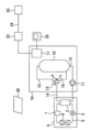
図1は、実施の形態1による貯湯式給湯装置を示す図である。図1に示すように、本実施の形態の貯湯式給湯装置は、ヒートポンプユニット6と、タンクユニット18とを備える。ヒートポンプユニット6は、電力を消費して水を加熱する加熱手段に相当する。ヒートポンプユニット6は、ヒートポンプサイクルの運転をすることで水を加熱する。ヒートポンプユニット6は、圧縮機1と、水冷媒熱交換器2と、膨張弁3と、空気熱交換器4と、冷媒循環配管5とを備える。水と、圧縮機1により加熱された冷媒とが水冷媒熱交換器2にて熱を交換することで水が加熱される。水冷媒熱交換器2を通過した冷媒は、膨張弁3により減圧されて気液二相となる。気液二相となった冷媒は、空気熱交換器4を通過する間に外気の熱を吸収して蒸発した後、圧縮機1に吸入される。ヒートポンプユニット6の加熱能力は、単位時間当たりに水に与える熱量であり、単位はワットである。ヒートポンプユニット6の加熱能力は、調整可能でもよい。例えば、圧縮機1の回転速度を変えてヒートポンプユニット6の加熱能力を変えることで、ヒートポンプユニット6の消費電力を調整可能である。
Embodiment 1.
FIG. 1 is a diagram showing a hot water storage type hot water supply apparatus according to Embodiment 1. FIG. As shown in FIG. 1 , the hot water storage type hot water supply apparatus of the present embodiment includes a heat pump unit 6 and a
タンクユニット18内には、湯水を貯留する貯湯タンク10と、循環ポンプ11と、切替弁12とが設置されている。ヒートポンプユニット6とタンクユニット18とは、ヒートポンプ往き配管13と、ヒートポンプ戻り配管14と、電気配線(図示省略)とを介して接続されている。ヒートポンプ往き配管13は、貯湯タンク10の下部と、水冷媒熱交換器2の入水口との間をつなぐ。ヒートポンプ往き配管13の途中に循環ポンプ11が接続されている。切替弁12は、流入口であるAポートと、第一出口となるBポートと、第二出口となるCポートとを有する。ヒートポンプ戻り配管14は、水冷媒熱交換器2の出湯口と、切替弁12のAポートとの間をつなぐ。切替弁12のBポートは、貯湯配管15を介して、貯湯タンク10の上部に接続されている。切替弁12のCポートは、バイパス配管16を介して、貯湯タンク10の下部に接続されている。
A hot
貯湯タンク10の下部には、給水配管(図示省略)がさらに接続されている。水道等の外部の水源から供給される水が、給水配管を通って、貯湯タンク10内に流入し、貯留される。貯湯タンク10内では、温度による水の密度の差によって、上側が高温で下側が低温になる温度成層を形成することができる。貯湯タンク10から、蛇口、シャワー、浴槽等の給湯先へ給湯するための配管及び混合弁等がタンクユニット18内にさらに設けられているが、図示を省略する。貯湯タンク10から給湯すると、給水配管からの水が貯湯タンク10の下部に流入することで、貯湯タンク10内は常に満水状態に維持される。
A water supply pipe (not shown) is further connected to the lower portion of the hot
本実施の形態の貯湯式給湯装置は、制御手段としての制御部17を備えている。制御部17は、貯湯式給湯装置に含まれる各構成要素と電気的に接続されており、貯湯式給湯装置の運転を制御する。制御部17は、例えば、少なくとも一つのメモリと、少なくとも一つのプロセッサとを備えていてもよい。図示の例では、タンクユニット18内に制御部17が設置されているが、ヒートポンプユニット6内に制御部17を設置してもよい。また、単一の制御部17に限らず、異なる場所に配置された複数の制御装置が通信により連携することで貯湯式給湯装置の動作を制御してもよい。
The hot water storage type hot water supply apparatus of the present embodiment includes a
貯湯式給湯装置は、沸上げ運転を実行できる。沸上げ運転は、ヒートポンプユニット6により貯湯タンク10の水を加熱する運転である。沸上げ運転のときには以下のようになる。ヒートポンプユニット6と循環ポンプ11とが運転される。貯湯タンク10内の下部の低温水がヒートポンプ往き配管13を通って水冷媒熱交換器2に流入する。低温水は、水冷媒熱交換器2内で加熱されて湯すなわち高温水になる。この高温水がヒートポンプ戻り配管14、切替弁12、及び貯湯配管15を通って貯湯タンク10の上部に流入する。貯湯タンク10内で上から下に向かって高温水が徐々に貯えられていく。
A hot water storage type hot water supply apparatus can perform a boiling operation. The boiling operation is an operation in which the heat pump unit 6 heats the water in the hot
貯湯タンク10内の貯湯量及び蓄熱量を検出するための複数の貯湯温度センサ(図示省略)が貯湯タンク10に設置されている。また、給湯に使用された熱量を検出するための給湯温度センサ、給湯流量センサ等(図示省略)がタンクユニット18内の配管に設置されている。制御部17は、それらのセンサで検出される情報に応じて、沸上げ運転により貯湯タンク10に蓄える熱量を制御する。例えば、制御部17は、過去所定期間(例えば過去2週間)における給湯使用熱量を統計的に処理した学習結果に応じて、貯湯タンク10に蓄える熱量を制御してもよい。
A plurality of hot water temperature sensors (not shown) for detecting the amount of hot water and heat stored in the
制御部17と、リモコン20との間は、有線通信または無線通信により、双方向に通信可能である。制御部17とリモコン20とがネットワークを介して通信可能でもよい。リモコン20は、ユーザインターフェースの例である。リモコン20は、情報を表示する表示部と、使用者が操作する操作部とを有する。リモコン20は表示部及び操作部の両方の機能を有するタッチスクリーンを備えてもよい。使用者等の人間は、リモコン20を操作することで、貯湯式給湯装置を遠隔操作したり、各種の設定などを行ったりすることが可能である。リモコン20の表示部は、使用者等の人間に情報を報知する報知手段としての機能を有する。リモコン20は、例えば台所、リビング、浴室などの壁に設置されたものでもよい。
Two-way communication is possible between the
制御部17には、貯湯式給湯装置が備える各種のセンサの出力と、リモコン20に対する使用者の操作内容の情報などが入力される。制御部17は、これらの入力情報に基づいてヒートポンプユニット6及びタンクユニット18の動作をそれぞれ制御する。
The
制御部17は、ブロードバンドルーター33と通信可能に接続されている。情報入力デバイス35は、インターネット回線34とブロードバンドルーター33とを介して、制御部17と通信可能である。情報入力デバイス35は、例えば、使用者が所持するスマートフォンでもよい。
The
本実施の形態の貯湯式給湯装置を有する家庭に太陽光発電装置30が設けられている。以下では、当該家庭を単に「家庭」と称する。太陽光発電装置30は、太陽光を受けて発電する太陽電池等を備える。太陽光発電装置30により発電された直流電力は、パワーコンディショナ(図示省略)により、交流電力に変換され、家庭に供給される。家庭内の貯湯式給湯装置と、貯湯式給湯装置以外の電気機器とは、太陽光発電装置30により発電された電力により作動可能である。太陽光発電装置30が発電しない夜間においては電力会社の商用電源からの電力が家庭に供給される。また、太陽光発電装置30の発電電力が家庭の消費電力に対して不足する場合には、その不足分の電力が商用電源から家庭に供給される。
A solar
本実施の形態の貯湯式給湯装置は、沸上げ運転として、夜間に商用電源から供給される電力を用いて行う夜間沸上げ運転と、昼間に太陽光発電装置30により発電された電力を用いて行う昼間沸上げ運転とを実行可能である。制御部17は、深夜時間帯に商用電源から供給される単価の安い深夜電力を用いて夜間沸上げ運転を実施してもよい。深夜時間帯の開始時刻は、例えば22時あるいは23時である。太陽光発電装置30により発電された電力から、貯湯式給湯装置以外の電気機器が消費する電力を差し引いた値を、以下「余剰電力」と称する。本実施の形態であれば、余剰電力を活用した昼間沸上げ運転により貯湯タンク10に熱を蓄えるので、夜間沸上げ運転により貯湯タンク10に蓄える必要のある熱量が減る。それゆえ、夜間沸上げ運転の消費電力量を低減できるので、使用者が電力会社に支払う電気料金を軽減できる。
The hot water storage type hot water supply apparatus of the present embodiment performs a nighttime heating operation using electric power supplied from a commercial power source during the nighttime as a heating operation, and a nighttime heating operation using electric power generated by the solar
一般的に、夜間沸上げ運転が開始される時刻は、例えば22時あるいは23時であり、浴槽の湯張りのような集中給湯負荷が発生する夕方の時間帯よりも遅い時刻である。このため、翌日の集中給湯負荷が発生する時刻までに、当夜の夜間沸上げ運転と、翌日の昼間沸上げ運転とにより、必要な熱量を貯湯タンク10に蓄える必要がある。以下の説明では、夜間沸上げ運転により貯湯タンク10に蓄える熱量を「夜間沸上げ量」と称し、昼間沸上げ運転により貯湯タンク10に蓄える熱量を「昼間沸上げ量」と称する。夜間沸上げ量は、夜間沸上げ運転の消費電力量[kWh]に比例する。昼間沸上げ量は、昼間沸上げ運転の消費電力量[kWh]に比例する。また、太陽光発電装置30が発電する電力量を「太陽光発電電力量[kWh]」と称する。
Generally, the time at which the nighttime heating operation is started is, for example, 22:00 or 23:00, which is later than the evening hours when a concentrated hot water supply load such as filling the bathtub with hot water occurs. Therefore, it is necessary to store the required amount of heat in the hot
余剰電力を活用して昼間沸上げ運転を行う場合、どの程度の昼間沸上げ量が見込めるかは、翌日の太陽光発電電力量に応じて異なる。翌日の昼間沸上げ量が多く見込める場合には、当夜の夜間沸上げ量は少なくてよいので、夜間沸上げ量を少なくして夜間沸上げ運転の消費電力量を抑制することが電気料金抑制につながる。しかしながら、そのようにして夜間沸上げ量を抑制した日に天気が予想よりも悪くなると、実際の太陽光発電電力量が期待よりも少なくなり、昼間沸上げ量が見込みを下回る。その結果、必要な熱量を貯湯タンク10に蓄えることができなくなる。その場合、単価の高い昼間の電力を商用電源から買電して昼間沸上げ運転を行うことになり、電気料金が上昇する。それらの事態を防止するためには、夜間沸上げ運転の開始前に、翌日の太陽光発電電力量を精度良く予測することが重要となる。
When the surplus power is used to perform the daytime heating operation, the amount of daytime heating that can be expected differs depending on the amount of photovoltaic power generation on the next day. If the amount of heating during the daytime on the next day is expected to be large, the amount of heating at nighttime that night may be small. Connect. However, if the weather turns worse than expected on the day on which the nighttime heating amount is suppressed in this way, the actual photovoltaic power generation amount will be less than expected, and the daytime heating amount will be less than expected. As a result, the required amount of heat cannot be stored in the hot
情報入力デバイス35は、太陽光発電装置30の発電能力に関する情報である発電能力情報と、太陽光発電装置30の所在地に関する情報である所在地情報とを使用者が入力可能であるように構成されている。発電能力情報は、例えば、太陽光発電装置30の定格発電能力[kW]の値の情報を含む。すなわち、発電能力情報は、太陽光発電装置30のシステム容量の情報に相当する。制御部17は、使用者が情報入力デバイス35に入力した発電能力情報及び所在地情報を、インターネット回線34及びブロードバンドルーター33を介して受信できる。
The
制御部17は、発電能力情報と、所在地情報と、翌日の天気予報情報とを用いて、翌日の太陽光発電電力量を予測する。太陽光発電装置30が発電する電力は、日射量に応じて変化する。日射量は、天気によって変化する。また、同じ天気でも、時間ごとの日射量は、緯度及び経度に応じて異なるので、太陽光発電装置30の所在地によって異なる。制御部17は、所在地情報と、翌日の天気予報情報とを用いることで、翌日の日射量を精度良く予測できる。制御部17は、その予測した翌日の日射量と、発電能力情報とを用いることで、翌日の太陽光発電電力量を予測する。
The
制御部17は、ネットワークにより配信された翌日の天気予報情報を受信してもよい。例えば、気象庁あるいは気象予測会社からインターネット回線34により配信された翌日の天気予報情報を、ブロードバンドルーター33を介して制御部17が受信してもよい。制御部17は、受信した天気予報情報のうち、太陽光発電装置30の所在地についての天気予報情報を用いて、翌日の日射量を予測する。
The
また、翌日の天気予報情報を使用者が情報入力デバイス35に入力し、その天気予報情報を、インターネット回線34及びブロードバンドルーター33を介して制御部17が受信してもよい。この場合、ネットワークにより配信された天気予報情報を制御部17が受信可能な構成としなくてもよいので、より簡易なシステムとすることが可能となる。また、局所的な天気については、気象庁あるいは気象予測会社の天気予報よりも、その地で生活している使用者が予測する天気の方が当たる確率が高い場合もある。そのような場合に翌日の天気予報情報を使用者が情報入力デバイス35に入力することで、太陽光発電電力量の予測精度が向上する。なお、使用者が情報入力デバイス35に入力した天気予報情報と、ネットワークにより配信された天気予報情報との両方を制御部17が受信してもよい。その場合に、いずれの天気予報情報を制御部17が用いるかを使用者がリモコン20または情報入力デバイス35を操作することで事前に設定できるように構成してもよい。
Alternatively, the user may input weather forecast information for the next day into the
なお、本実施の形態では、情報入力デバイス35がインターネット回線34及びブロードバンドルーター33を介して制御部17と通信するが、変形例として、情報入力デバイス35と制御部17とが直接的に通信可能な構成としてもよい。また、発電能力情報、所在地情報、及び天気予報情報のうちの少なくとも一つの情報を使用者がリモコン20に入力できるように構成してもよい。すなわち、リモコン20を情報入力デバイスとして使用してもよい。
In this embodiment, the
夜間沸上げ運転を開始する前に、制御部17は、上記のようにして、翌日の太陽光発電電力量を精度良く予測できる。その予測された翌日の太陽光発電電力量を以下「太陽光発電電力量予測値」と称する。太陽光発電電力量予測値が大きい場合には翌日の昼間沸上げ量が多く見込めるので、当夜の夜間沸上げ量は少なくてよい。このため、制御部17は、太陽光発電電力量予測値が大きい場合には、太陽光発電電力量予測値が小さい場合に比べて、夜間沸上げ運転の消費電力量が少なくなるように制御する。これにより、電気料金を抑制できる。制御部17は、太陽光発電電力量予測値が大きいほど、夜間沸上げ運転の消費電力量を少なくしてもよい。すなわち、制御部17は、太陽光発電電力量予測値が小さいほど、夜間沸上げ運転の消費電力量を多くしてもよい。そのようにすることで、翌日の昼間沸上げ量が少ないと予想される場合でも、貯湯タンク10の蓄熱量が不足することを確実に抑制できる。
Before starting the nighttime heating operation, the
制御部17が太陽光発電電力量予測値を計算する方法の一例を以下に説明する。まず、制御部17は、所在地情報と天気予報情報とを用いて日射量と時刻との関係を予測する。例えば、日中の天気予報が快晴である場合には、日射量として、午前9時台に200W/m2、午前10時台に400W/m2、午前11時台に800W/m2、のように予測する。この時間ごとの日射量の予測値は、緯度及び経度に応じて補正されている値である。次いで、制御部17は、発電効率を80%と設定する。太陽光発電装置30の定格発電能力が3kWであるとすると、上記の条件から、制御部17は、時間ごとの太陽光発電装置30の予測発電電力として、午前9時台に0.48kW、午前10時台に0.96kW、午前11時台に1.92kW、のように計算する。制御部17は、この予測発電電力を積分することにより、太陽光発電電力量予測値を算出できる。なお、制御部17は、天気予報が快晴などのように雲量が少ないほど発電効率の値を高く設定し、曇りまたは雨などのように雲量が多いほど発電効率の値を低く設定する。
An example of the method by which the
なお、上記の例では、時間ごとの日射量を用いて制御部17が太陽光発電電力量予測値を計算しているが、変形例として、制御部17は、日中の平均日射量を用いて太陽光発電電力量予測値を計算してもよい。
In the above example, the
本実施の形態では、所在地情報として、太陽光発電装置30の所在地の郵便番号を用いてもよい。制御部17は、予めメモリに記憶されたデータに基づいて、郵便番号から緯度及び経度を求めることができる。所在地情報として郵便番号を用いることで、使用者が所在地情報を情報入力デバイス35に入力する作業が容易になる。ただし、本開示における所在地情報は郵便番号に限定されない。例えば、太陽光発電装置30の所在地の都道府県名及び市町村名を使用者が所在地情報として情報入力デバイス35に入力してもよい。
In this embodiment, the postal code of the location of the photovoltaic
翌日の昼間に貯湯式給湯装置以外の電気機器が消費すると予測される電力に関する情報を以下「電力負荷情報」と称する。電力負荷情報を使用者が情報入力デバイス35に入力可能としてもよい。家庭内で貯湯式給湯装置以外の電気機器が消費する電力を以下「家庭内使用電力」と称する。家庭内使用電力は、生活パターンに応じて決まると考えられる。使用者は、日頃の生活パターンと家庭内使用電力との関係を把握することで、翌日の家庭内使用電力を予測できる。使用者は、翌日の昼間の時間ごとの家庭内使用電力の予測値を電力負荷情報として情報入力デバイス35に入力してもよい。
Information about electric power expected to be consumed by electrical equipment other than the hot water storage type hot water supply apparatus during the daytime of the next day is hereinafter referred to as "power load information". The power load information may be input to the
制御部17は、上述した電力負荷情報と、発電能力情報と、所在地情報と、天気予報情報とを用いて、翌日の余剰電力である予測余剰電力を予測することができる。例えば、制御部17は、時間ごとの太陽光発電装置30の予測発電電力から、電力負荷情報における時間ごとの家庭内使用電力の予測値を減算することで、予測余剰電力を算出できる。
The
昼間沸上げ運転に必要な電力は、ヒートポンプユニット6を動作させる電力と、循環ポンプ11を動作させる電力との合計である。本実施の形態の貯湯式給湯装置は、昼間沸上げ運転に必要な電力よりも予測余剰電力が小さい場合に商用電源から供給される電力を併用して翌日の昼間沸上げ運転を実行する制御モードを有していてもよい。当該制御モードを以下「第一モード」と称する。第一モードの制御によれば、昼間沸上げ運転に必要な電力よりも予測余剰電力が小さい場合にも余剰電力を活用して貯湯タンク10に熱を蓄えることができるので、余剰電力をより有効に活用できる。
The electric power required for the daytime heating operation is the sum of the electric power for operating the heat pump unit 6 and the electric power for operating the
また、本実施の形態の貯湯式給湯装置は、昼間沸上げ運転に必要な電力よりも予測余剰電力が小さい場合に翌日の昼間沸上げ運転を実行しないようにする制御モードを有していてもよい。当該制御モードを以下「第二モード」と称する。第二モードの制御によれば、単価の高い昼間の電力を商用電源から買電することを確実に防止できる。第二モードの場合、制御部17は、夜間沸上げ運転の開始前に、昼間沸上げ運転に必要な電力よりも予測余剰電力が小さいかどうかを判断し、昼間沸上げ運転に必要な電力よりも予測余剰電力が小さい場合には、昼間沸上げ量をゼロと予測して、夜間沸上げ量を決定する。
Further, the hot water storage type hot water supply apparatus of the present embodiment has a control mode in which the daytime heating operation of the next day is not executed when the predicted surplus power is smaller than the power required for the daytime heating operation. good. This control mode is hereinafter referred to as "second mode". According to the control in the second mode, it is possible to reliably prevent the purchase of electricity from the commercial power source during the day when the unit price is high. In the case of the second mode, the
本実施の形態の貯湯式給湯装置は、第一モードと第二モードとの両方の制御モードを備えていてもよいし、いずれか一方の制御モードだけを備えたものでもよい。第一モードと第二モードとの両方を備える場合には、第一モードと第二モードとのいずれを実行するかを使用者が選択可能としてもよい。そのようにすることで、利便性が向上する。 The hot water storage type hot water supply apparatus of the present embodiment may have both the first mode and the second control mode, or may have only one of the control modes. When both the first mode and the second mode are provided, the user may be able to select which of the first mode and the second mode is to be executed. By doing so, convenience is improved.
昼間沸上げ運転を開始する前または昼間沸上げ運転の実行中に、当日の天気予報を制御部17が受信してもよい。この場合、使用者が情報入力デバイス35に入力した当日の天気予報を制御部17が受信してもよいし、気象庁あるいは気象予測会社からインターネット回線34により配信された当日の天気予報情報を制御部17が受信してもよい。昼間沸上げ運転を開始する前または昼間沸上げ運転の実行中に当日の天気予報を受信した場合に、制御部17は、その受信した当日の天気予報に基づいて、太陽光発電電力量が前日の予測よりも小さくなるかどうかを判定する。そして、制御部17は、太陽光発電電力量が前日の予測よりも小さくなると判定した場合には、昼間沸上げ運転の消費電力量が予定よりも小さくなるように制御する。これにより、単価の高い昼間の電力を商用電源から買電することを確実に抑制できる。
The
制御部17は、一日のうちで、夜間沸上げ運転の消費電力量が昼間沸上げ運転の消費電力量よりも大きくなるように制御することが望ましい。昼間電力よりも深夜電力の方を優先的に利用することで、深夜電力機器として電力会社に認定されるため、使用者がコストメリットを得ることができる。
It is desirable that the
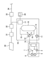
図2は、比較例の貯湯式給湯装置を示す図である。図2を参照して、比較例の貯湯式給湯装置について説明するが、実施の形態1の貯湯式給湯装置と共通または対応する要素には、同一の符号を付して、共通する説明を簡略化または省略する。エネルギー管理装置31は、貯湯式給湯装置を含む家庭内の電気機器を管理する。制御部17は、通信アダプタ32を介して、エネルギー管理装置31と通信可能に接続されている。太陽光発電装置30の発電量は、エネルギー管理装置31にて計測される。エネルギー管理装置31は、太陽光発電装置30の発電電力から家庭内使用電力を減算することで余剰電力を算出することができる。その余剰電力の情報は、通信アダプタ32を介して制御部17に伝達される。また、通信アダプタ32は、ブロードバンドルーター33に接続することが可能である。通信アダプタ32は、ブロードバンドルーター33を介してインターネット回線34と接続することにより天気予報の情報等をインターネットを介して取得することが可能であり、その取得した情報を制御部17に送信することが可能である。制御部17は、上記のようにして得られた余剰電力の情報と、翌日の天気予報情報と、貯湯タンク10の蓄熱量の情報等に基づいて、当夜の夜間沸上げ量を決定する。このような比較例の貯湯式給湯装置は、エネルギー管理装置31及び通信アダプタ32を必要とするシステムのため、システム価格が高価になる。これに対し、実施の形態1の貯湯式給湯装置であれば、エネルギー管理装置31及び通信アダプタ32が不要であるので、システム価格を低減することが可能となる。
FIG. 2 is a diagram showing a hot water storage type hot water supply apparatus of a comparative example. Referring to FIG. 2, the storage-type hot water supply apparatus of the comparative example will be described. Elements common to or corresponding to those of the storage-type hot water supply apparatus of Embodiment 1 are denoted by the same reference numerals, and the common description is simplified. reduced or omitted. The
1 圧縮機、 2 水冷媒熱交換器、 3 膨張弁、 4 空気熱交換器、 5 冷媒循環配管、 6 ヒートポンプユニット、 10 貯湯タンク、 11 循環ポンプ、 12 切替弁、 13 ヒートポンプ往き配管、 14 ヒートポンプ戻り配管、 15 貯湯配管、 16 バイパス配管、 17 制御部、 18 タンクユニット、 20 リモコン、 30 太陽光発電装置、 31 エネルギー管理装置、 32 通信アダプタ、 33 ブロードバンドルーター、 34 インターネット回線、 35 情報入力デバイス
1 compressor 2 water-
Claims (10)
電力を消費して水を加熱する加熱手段と、
前記加熱手段により前記貯湯タンクの水を加熱する沸上げ運転を制御する制御手段と、
を備え、
前記沸上げ運転として、夜間に商用電源から供給される電力を用いて行う夜間沸上げ運転と、昼間に太陽光発電装置により発電された電力を用いて行う昼間沸上げ運転とを実行可能であり、
前記制御手段は、使用者が情報入力デバイスに入力した情報を受信可能であり、
前記情報入力デバイスは、前記太陽光発電装置の発電能力に関する情報である発電能力情報と、前記太陽光発電装置の所在地に関する情報である所在地情報とを使用者が入力可能であるように構成され、
前記制御手段は、前記発電能力情報と、前記所在地情報と、翌日の天気予報情報とを用いて、翌日に前記太陽光発電装置が発電する電力量である太陽光発電電力量を予測し、
前記制御手段は、前記予測された翌日の前記太陽光発電電力量が大きい場合には、前記予測された翌日の前記太陽光発電電力量が小さい場合に比べて、前記夜間沸上げ運転の消費電力量が小さくなるように制御し、
家庭内の電気機器を管理するエネルギー管理装置と接続されていない貯湯式給湯装置。 a water storage tank; and
a heating means for consuming electric power to heat water;
a control means for controlling a boiling operation for heating the water in the hot water storage tank by the heating means;
with
As the heating operation, it is possible to perform a nighttime heating operation using power supplied from a commercial power supply at night and a daytime heating operation using power generated by a solar power generation device during the daytime. ,
The control means is capable of receiving information input by a user into an information input device,
The information input device is configured so that a user can input power generation capacity information, which is information regarding the power generation capacity of the solar power generation device, and location information, which is information regarding the location of the solar power generation device,
The control means uses the power generation capacity information, the location information, and the next day's weather forecast information to predict the amount of photovoltaic power generation, which is the amount of power to be generated by the photovoltaic power generation device on the next day,
When the predicted amount of photovoltaic power generation on the next day is large, the control means controls the power consumption of the nighttime heating operation compared to when the predicted amount of photovoltaic power generation on the next day is small. Control so that the amount is small ,
A hot water storage type water heater that is not connected to an energy management device that manages electrical appliances in the home .
翌日の昼間に前記貯湯式給湯装置以外の電気機器が消費すると予測される電力に関する情報である電力負荷情報を使用者が前記情報入力デバイスに入力可能であり、
前記制御手段は、前記発電能力情報と、前記所在地情報と、前記天気予報情報と、前記電力負荷情報とを用いて、翌日の前記余剰電力である予測余剰電力を予測し、
前記昼間沸上げ運転に必要な電力よりも前記予測余剰電力が小さい場合に前記商用電源から供給される電力を併用して翌日の前記昼間沸上げ運転を実行する第一モードと、前記昼間沸上げ運転に必要な電力よりも前記予測余剰電力が小さい場合に翌日の前記昼間沸上げ運転を実行しないようにする第二モードとのうちのいずれか一方または両方の制御モードを備える請求項1から請求項5のいずれか一項に記載の貯湯式給湯装置。 The hot water storage type hot water supply device is capable of executing the daytime heating operation using surplus power out of power generated by the solar power generation device,
A user can input power load information, which is information about power expected to be consumed by electrical equipment other than the hot water storage type hot water supply apparatus during the daytime of the next day, into the information input device;
The control means uses the power generation capacity information, the location information, the weather forecast information, and the power load information to predict the predicted surplus power that is the surplus power for the next day,
a first mode for performing the daytime heating operation on the next day using the electric power supplied from the commercial power source when the predicted surplus power is smaller than the electric power required for the daytime heating operation; and a second mode for not executing the daytime heating operation on the next day when the predicted surplus power is smaller than the power required for the operation, or a control mode for both of them. Item 6. The hot water storage type hot water supply device according to any one of items 5.
前記第一モードと前記第二モードとのいずれを実行するかを使用者が選択可能である請求項6に記載の貯湯式給湯装置。 comprising both the first mode and the second mode of control,
7. The hot water storage type hot water supply apparatus according to claim 6, wherein a user can select which of said first mode and said second mode is to be executed.
前記制御手段は、前記当日の天気予報に基づいて、前記太陽光発電電力量が前日の予測よりも小さくなると判定した場合には、前記昼間沸上げ運転の消費電力量が予定よりも小さくなるように制御する請求項1から請求項7のいずれか一項に記載の貯湯式給湯装置。 The control means is capable of receiving a weather forecast for the day before starting the daytime heating operation or during execution of the daytime heating operation,
When the control means determines that the solar power generation amount will be smaller than the previous day's forecast based on the weather forecast for the day, the control means controls the power consumption of the daytime heating operation to be smaller than planned. 8. The hot water storage type hot water supply apparatus according to any one of claims 1 to 7, wherein the hot water supply is controlled to .
前記所在地情報は、郵便番号であり、
前記制御手段は、前記郵便番号を用いて前記所在地の緯度及び経度を求め、前記緯度及び前記経度と前記天気予報情報とを用いて翌日の日射量を予測し、その予測された日射量と前記定格発電能力の値とを用いて、翌日の前記太陽光発電電力量を予測する請求項1から請求項9のいずれか一項に記載の貯湯式給湯装置。 The power generation capacity information is a value of the rated power generation capacity of the photovoltaic power generation device,
the location information is a postal code;
The control means obtains the latitude and longitude of the location using the zip code, predicts the next day's solar radiation using the latitude and longitude, and the weather forecast information, and calculates the predicted solar radiation and the The hot water storage type hot water supply apparatus according to any one of claims 1 to 9, wherein the photovoltaic power generation amount for the next day is predicted using the value of the rated power generation capacity.
Priority Applications (1)
| Application Number | Priority Date | Filing Date | Title |
|---|---|---|---|
| JP2019214336A JP7331663B2 (en) | 2019-11-27 | 2019-11-27 | Storage hot water heater |
Applications Claiming Priority (1)
| Application Number | Priority Date | Filing Date | Title |
|---|---|---|---|
| JP2019214336A JP7331663B2 (en) | 2019-11-27 | 2019-11-27 | Storage hot water heater |
Publications (2)
| Publication Number | Publication Date |
|---|---|
| JP2021085600A JP2021085600A (en) | 2021-06-03 |
| JP7331663B2 true JP7331663B2 (en) | 2023-08-23 |
Family
ID=76087991
Family Applications (1)
| Application Number | Title | Priority Date | Filing Date |
|---|---|---|---|
| JP2019214336A Active JP7331663B2 (en) | 2019-11-27 | 2019-11-27 | Storage hot water heater |
Country Status (1)
| Country | Link |
|---|---|
| JP (1) | JP7331663B2 (en) |
Citations (5)
| Publication number | Priority date | Publication date | Assignee | Title |
|---|---|---|---|---|
| JP2008002702A (en) | 2006-06-20 | 2008-01-10 | Matsushita Electric Ind Co Ltd | Hot water storage type water heater, hot water supply method and program |
| JP2014224660A (en) | 2013-05-17 | 2014-12-04 | 株式会社コロナ | Heat pump hot water storage type water heater compatible with photovoltaic power generator |
| JP2019060503A (en) | 2017-09-25 | 2019-04-18 | 四国電力株式会社 | Storage type electric water heater operation system for each block based on control information transmission |
| JP2019095102A (en) | 2017-11-20 | 2019-06-20 | 三菱電機株式会社 | Hot water storage type water heater |
| JP2019168133A (en) | 2018-03-22 | 2019-10-03 | 三菱電機株式会社 | Hot water storage type hot water system |
-
2019
- 2019-11-27 JP JP2019214336A patent/JP7331663B2/en active Active
Patent Citations (5)
| Publication number | Priority date | Publication date | Assignee | Title |
|---|---|---|---|---|
| JP2008002702A (en) | 2006-06-20 | 2008-01-10 | Matsushita Electric Ind Co Ltd | Hot water storage type water heater, hot water supply method and program |
| JP2014224660A (en) | 2013-05-17 | 2014-12-04 | 株式会社コロナ | Heat pump hot water storage type water heater compatible with photovoltaic power generator |
| JP2019060503A (en) | 2017-09-25 | 2019-04-18 | 四国電力株式会社 | Storage type electric water heater operation system for each block based on control information transmission |
| JP2019095102A (en) | 2017-11-20 | 2019-06-20 | 三菱電機株式会社 | Hot water storage type water heater |
| JP2019168133A (en) | 2018-03-22 | 2019-10-03 | 三菱電機株式会社 | Hot water storage type hot water system |
Also Published As
| Publication number | Publication date |
|---|---|
| JP2021085600A (en) | 2021-06-03 |
Similar Documents
| Publication | Publication Date | Title |
|---|---|---|
| JP5838825B2 (en) | Hot water storage hot water supply system | |
| JP6641455B2 (en) | Hot water supply system and water heater control method | |
| JP6044326B2 (en) | Hot water storage water heater and solar system | |
| WO2010114934A1 (en) | Healthy home graphical user interface method and device | |
| JP6191531B2 (en) | Hot water storage water heater | |
| JP6599558B2 (en) | Hot water supply system, water heater, and control method of water heater | |
| JP5904932B2 (en) | Hot water storage water heater | |
| JP2019095102A (en) | Hot water storage type water heater | |
| JP5904933B2 (en) | Hot water storage water heater | |
| JP5375670B2 (en) | Hybrid system | |
| JP6937636B2 (en) | Hot water storage type water heater, home system, and control method | |
| JP7331663B2 (en) | Storage hot water heater | |
| JP6719669B2 (en) | Control device, power management system, device control method and program | |
| JP7108220B2 (en) | Storage hot water heater | |
| JP7251507B2 (en) | Storage hot water heater | |
| WO2020225905A1 (en) | Storage type hot water supply system | |
| JP7294087B2 (en) | heat pump water heater | |
| JP7390811B2 (en) | Hot water supply control device, cloud server, hot water system, hot water supply control method and program | |
| JP6816706B2 (en) | Hot water storage type hot water supply device | |
| US20230324080A1 (en) | Heating system and related methods | |
| JP7005309B2 (en) | Hot water storage type hot water supply device | |
| JP2021196094A (en) | Storage type hot water supply device | |
| JP2023096640A (en) | Hot water storage type water heater | |
| JP2023093872A (en) | Hot water storage type hot water supply device | |
| JP2023060710A (en) | Storage water heater |
Legal Events
| Date | Code | Title | Description |
|---|---|---|---|
| A621 | Written request for application examination |
Free format text: JAPANESE INTERMEDIATE CODE: A621 Effective date: 20220525 |
|
| A977 | Report on retrieval |
Free format text: JAPANESE INTERMEDIATE CODE: A971007 Effective date: 20230224 |
|
| A131 | Notification of reasons for refusal |
Free format text: JAPANESE INTERMEDIATE CODE: A131 Effective date: 20230322 |
|
| A521 | Request for written amendment filed |
Free format text: JAPANESE INTERMEDIATE CODE: A523 Effective date: 20230420 |
|
| TRDD | Decision of grant or rejection written | ||
| A01 | Written decision to grant a patent or to grant a registration (utility model) |
Free format text: JAPANESE INTERMEDIATE CODE: A01 Effective date: 20230711 |
|
| A61 | First payment of annual fees (during grant procedure) |
Free format text: JAPANESE INTERMEDIATE CODE: A61 Effective date: 20230724 |
|
| R150 | Certificate of patent or registration of utility model |
Ref document number: 7331663 Country of ref document: JP Free format text: JAPANESE INTERMEDIATE CODE: R150 |