JP7323112B2 - LATENTIC PRINTED MATERIAL, PRODUCTION METHOD AND SOFTWARE FOR THE SAME - Google Patents
LATENTIC PRINTED MATERIAL, PRODUCTION METHOD AND SOFTWARE FOR THE SAME Download PDFInfo
- Publication number
- JP7323112B2 JP7323112B2 JP2022109399A JP2022109399A JP7323112B2 JP 7323112 B2 JP7323112 B2 JP 7323112B2 JP 2022109399 A JP2022109399 A JP 2022109399A JP 2022109399 A JP2022109399 A JP 2022109399A JP 7323112 B2 JP7323112 B2 JP 7323112B2
- Authority
- JP
- Japan
- Prior art keywords
- latent image
- pattern
- color component
- visible
- pattern data
- Prior art date
- Legal status (The legal status is an assumption and is not a legal conclusion. Google has not performed a legal analysis and makes no representation as to the accuracy of the status listed.)
- Active
Links
Images


Description
本発明は、銀行券、パスポート、有価証券、証明書、重要書類等の偽造や変造の防止が求められるセキュリティ印刷物の分野において、あらゆる印刷機やプリンタによる出力が可能な潜像印刷物、その作成方法及びその作成用ソフトウェアに関するものである。 The present invention relates to the field of security printed matter, such as banknotes, passports, negotiable securities, certificates, important documents, etc., in which the prevention of counterfeiting and alteration is required. and software for its creation.
銀行券、パスポート、有価証券、証明書、重要書類等のセキュリティ印刷物では、偽造や変造を防ぐことが重要である。これらの偽造防止策の一つに、網点や画線の配置、多層構造、特殊材料等によって印刷模様に手段と作用を加えることで、文字や図形等を目視では認識できないように潜像化させた印刷物(以下「潜像印刷物」という。)がある。その代表的なものとして、印刷物を複写機でコピーすると複写物上に潜像を発現させるコピー牽制画線を施した潜像印刷物がある。このような印刷物は、証明書や重要書類等において古くから採用されており、複写機で再現が容易な網点から成る潜像部と、複写機で再現が困難な網点から成る背景部で構成され、潜像部と背景部の濃度を一様とすることで、潜像を秘匿化している(例えば、特許文献1及び2参照)。
For security printed matter such as banknotes, passports, negotiable securities, certificates, and important documents, it is important to prevent forgery and alteration. As one of these anti-counterfeiting measures, by adding means and effects to the printed pattern through the arrangement of halftone dots and lines, a multi-layer structure, special materials, etc., characters and figures are made into latent images so that they cannot be recognized by the naked eye. There is a printed matter (hereinafter referred to as “latent image printed matter”) that has been printed. A typical example is a latent-image printed material having a copy-preventing image line that develops a latent image on the copied material when the printed material is copied by a copier. Such printed matter has long been used for certificates and important documents, and consists of a latent image portion made up of halftone dots that can be easily reproduced on a copier, and a background portion made up of halftone dots that are difficult to reproduce on a copier. The latent image is concealed by making the density of the latent image portion and the background portion uniform (see, for example,
また、本出願人も、連続階調の潜像を有するコピー牽制画線の潜像印刷物を出願している。これは、複写機によって再現される大きさの第1の要素を複数配置し、その面積率の大小で連続階調を形成する潜像部と、複写機によって再現されないハーフトーン濃度の第2の要素で形成する背景部を組み合わせ、単位面積当たりの第1の要素と第2の要素を合計した面積率が、印刷模様の全てにおいて同一となるように構成された潜像印刷物である(例えば、特許文献3参照)。 Applicant also has filed a latent image print of anti-copy images having a continuous tone latent image. In this method, a plurality of first elements having a size that can be reproduced by a copier are arranged, and the latent image portion that forms a continuous tone depending on the size of the area ratio, and a second halftone density that cannot be reproduced by a copier. It is a latent image printed material configured so that the total area ratio of the first element and the second element per unit area is the same in all printed patterns by combining the background part formed by the elements (for example, See Patent Document 3).
上述のようなコピー牽制効果を目的とした潜像印刷物は、いずれも、複写機でコピーした場合、複写物上に目視では認識できなかった潜像を発現させることを特徴としている。したがって、潜像部の網点や画線は、複写機で再現される形状や大きさで形成されており、背景部の網点や画線は、複写機で再現されない、もしくは再現が困難な形状や大きさで形成されている。すなわち、潜像部と背景部では網点や画線が異なっている。 All of the above-mentioned latent image printed materials for the purpose of preventing copying are characterized in that when they are copied by a copier, a latent image that cannot be visually recognized appears on the copied material. Therefore, the halftone dots and lines in the latent image portion are formed in a shape and size that can be reproduced by the copier, and the halftone dots and lines in the background portion cannot be reproduced by the copier, or are difficult to reproduce. formed by shape and size. That is, halftone dots and lines are different between the latent image portion and the background portion.
一方、印刷ではドットゲインという現象が発生する。非特許文献1によればドットゲインとは、原版又は刷版に形成された網点の直径よりも、印刷で紙に刷られたインキの網点の直径の方が大きくなる現象であり、刷版の網点部分に付着したインキが、刷版から紙あるいはブランケットへ転写される時にかかる圧力によって、圧し潰され広がることで起きるとされている。また、この現象は、インキの膜厚は網点の大きさに関係せず一定の厚みを持つため、印圧が同じであれば網点が広がる幅も同じになる。すなわち、網点が小さいほど、ドットゲインによって直径が大きくなる比率が高くなる傾向にある。
On the other hand, a phenomenon called dot gain occurs in printing. According to Non-Patent
例えば、特許文献1及び2に記載のような潜像印刷物で、潜像を秘匿化するために異なる大きさの網点同士を印刷物上で一様の濃度とするには、ドットゲインを考慮して、各々の網点の面積率を原版で変えておく必要がある。例えば、潜像部の網点(大)と背景部の網点(小)の印刷物上での面積率を20%に統一するならば、網点(大)の原版における面積率を18%、網点(小)の原版における面積率を15%といったように、印刷前の原版において印刷結果の面積率を見越した補正をしておくのが一般的な手法である。
For example, in latent image prints as described in
また、ドットゲインは印刷機に限られた現象ではなく、メカニズムは違うがプリンタによる原版の出力においても発生する。特にプリンタの場合は、プリンタの印刷方式や画質等の特性に応じて原版の設計値を補正する、いわゆるキャリブレーションと呼ばれる作業が必要となる。なお、本出願人は、このキャリブレーションの手法として、特許文献3に記載のような画線構成の潜像印刷物を対象に、潜像のテストチャート画像を予めプリンタにより出力し、その出力結果をフィードバックすることで、プリンタの特性に合わせたプロファイルを作成して適正な原版の設計値を導く方法と、その方法を利用した発給システムを出願している(例えば、特許文献4参照)。
In addition, dot gain is not a phenomenon limited to printing presses, but occurs also in the output of originals by printers, although the mechanism is different. Particularly in the case of a printer, a so-called calibration process is required to correct the design values of the original according to the printer's printing method, image quality, and other characteristics. As a method for this calibration, the applicant previously output a test chart image of the latent image with a printer for a latent image printed material having an image line configuration as described in
その一方で証明書等は、近年の社会的な利便性向上のため、例えば、全国のコンビニエンスストアに設置されたマルチコピー機を利用する出力サービスが展開されている。このようなサービスの場合、上述のようにプリンタの特性に合わせたプロファイルを作成する方法は、全国で5万5千店舗(2009 年12月現在)を超えるコンビニエンスストアのマルチコピー機の全台を対象とするのは現実的とはいえない。そのため、あらゆる印刷機やプリンタによる出力において、その出力結果をフィードバックする必要がない潜像印刷物が求められていた。 On the other hand, for certificates and the like, in order to improve social convenience in recent years, for example, output services using multi-copiers installed in convenience stores nationwide have been developed. In the case of such a service, the method of creating a profile that matches the characteristics of the printer, as described above, requires all the multi-function copiers of more than 55,000 convenience stores nationwide (as of December 2009). It is not realistic to target them. Therefore, there has been a demand for a latent image printed material that does not require feedback of the output result in output by any printing machine or printer.
また、特許文献1、2及び3に記載のようなコピー牽制効果を目的とした潜像印刷物は、複写物上に潜像を発現させるものであるため、複写物の真偽判定、すなわちそれが原本ではないことを判定するのは容易である。しかしながら、原本に対する真偽判定として潜像を確認するには、複写機で潜像印刷物をコピーして、潜像を発現させる作業が必要となる。これは、市役所の窓口のように複写機が設置されている環境に依存する方法であり、駅や空港等の公共交通機関を利用した移動時や、施設等の入場時には、簡易的に潜像を確認できないという不便さがあった。
In addition, since the latent image printed matter for the purpose of copy restraint effect as described in
本出願人は、前述した不便を解消するために、特許文献5に記載された印刷物の読取検査装置を出願している。これは、潜像印刷物を撮影して画像を取得し、その画像から潜像模様の特異点を抽出する処理を行うことで、潜像を可視化して画面表示するための読取検査装置である。
The applicant of the present application has filed an application for a printed matter reading and inspecting apparatus described in
さらに本出願人は、特許文献6に示す潜像印刷物を出願している。この潜像印刷物は、第1の画線を有する第1のユニットを複数配列した潜像部と、第2の画線を有する第2のユニットを複数配列した背景部とを備え、第1の画線、第2の画線とは同色であり、かつ、第1の画線と第2の画線とは形状及び大きさが同一で、配置される角度が90度の範囲内で異なるものである。このような構成によれば、印刷条件が変化した場合にも、網点や画線の面積率の増加量(ドットゲイン量)も連動して変化するため、印刷物に形成された潜像模様が目視により視認されるという顕像化を防ぐことができる。
Furthermore, the applicant of the present application has applied for a latent image printed matter shown in
しかしながら、この潜像印刷物を構成する基材と異なる第1の画線及び第2の画線の色は同一色に限られており、その結果、読取検査装置に画面表示される潜像模様は、単色(モノクロ)に限定されていた。このため、顔画像や風景画をはじめとするフルカラーや階調変化を伴う様々な美麗な画像は表現することが困難であった。特に、フルカラーの顔画像等をパスポートや身分証明書に潜像模様として適用する場合、読取検査装置により潜像模様をカラーで可視化し、それによる高度な真偽判別や個人認証を行うことはできなかった。 However, the colors of the first image line and the second image line, which are different from the substrate constituting the latent image print, are limited to the same color, and as a result, the latent image pattern displayed on the screen of the reading and inspection device is , was limited to a single color (monochrome). For this reason, it has been difficult to express various beautiful images accompanied by full-color and gradation changes, such as face images and landscape paintings. In particular, when a full-color facial image is used as a latent image pattern on a passport or identification card, it is not possible to visualize the latent image pattern in color using a reading inspection device and perform advanced authenticity determination and personal authentication. I didn't.
前述したように、従来の潜像印刷物は、読取検査装置に画面表示される潜像模様が単色の模様に限定され、顔模様や風景画等の様々な美麗な模様の表現が困難であるとともに、パスポートや身分証明書の顔模様等による高度な真偽判別や個人認証ができないという課題があった。 As described above, in the conventional latent image printed matter, the latent image pattern displayed on the screen of the reading inspection device is limited to a single color pattern, and it is difficult to express various beautiful patterns such as facial patterns and landscape images. , there was a problem that advanced authenticity discrimination and personal authentication by facial patterns etc. of passports and identification cards could not be performed.
本発明は、上記課題の解決を目的とするものであり、印刷条件が変化した場合にも潜像模様の秘匿化が確保されるとともに、フルカラーの模様表現が可能であり、それによりパスポートや身分証明書の顔模様等による高度な真偽判別や個人認証も可能とする潜像印刷物、その作成方法及びその作成用ソフトウェアを提供することを目的とする。 SUMMARY OF THE INVENTION It is an object of the present invention to solve the above-mentioned problems. It is an object of the present invention to provide a latent-image printed matter, a method for producing the printed matter, and software for producing the printed matter, which enable high-level authenticity determination and personal authentication by means of a face pattern of a certificate.
本発明の潜像印刷物は、基材の少なくとも一部に潜像模様を形成するための印刷領域を有し、潜像模様は、少なくとも第1の色成分模様と第2の色成分模様とを有し、印刷領域には、第1の色成分模様に対応して形成された第1の潜像画線、第2の色成分模様に対応して形成された第2の潜像画線のいずれか一つをそれぞれ含む複数のユニットが所定間隔で配置されており、第1の潜像画線と第2の潜像画線は、ユニット内において面積率が等しく、かつ、配置される角度及び/又は形状が相互に異なることを特徴とする。 The latent image print of the present invention has a printing area for forming a latent image pattern on at least a part of a substrate, and the latent image pattern comprises at least a first color component pattern and a second color component pattern. a first latent image line formed corresponding to the first color component pattern and a second latent image line formed corresponding to the second color component pattern in the print area; A plurality of units each containing either one are arranged at predetermined intervals, and the first latent image line and the second latent image line have the same area ratio in the unit and are arranged at an angle and/or differ in shape from each other.
また、本発明の潜像印刷物は、第1の潜像画線像と第2の潜像画線とが同一色であってよい。 Further, in the latent image printed material of the present invention, the first latent image line image and the second latent image line image may be of the same color.
また、本発明の潜像印刷物は、印刷領域にはさらに可視模様が形成され、可視模様は、それぞれのユニット内において、第1の潜像画線又は第2の潜像画線が形成されていない領域に設けられた可視模様形成領域に形成され、可視模様形成領域の濃度が可視模様の階調濃度に対応するものであってよい。 Further, in the latent image printed material of the present invention, a visible pattern is further formed in the printing area, and the visible pattern includes the first latent image line or the second latent image line formed in each unit. It may be formed in a visible pattern forming area provided in an area where no visible pattern is formed, and the density of the visible pattern forming area may correspond to the gradation density of the visible pattern.
本発明の潜像印刷物の作成方法は、潜像模様の基模様を取得するステップと、基模様を少なくとも第1の色成分と第2の色成分とに色分解を行い、第1の色成分模様データと第2の色成分模様データとを生成するステップと、第1の色成分模様データと第2の色成分模様データとに誤差拡散ディザを行い、2階調化した第1の色成分階調模様データと第2の色成分階調模様データとを生成するステップと、第1の色成分階調模様データを第1の色成分で着色し、第2の色成分階調模様データを前記第2の色成分で着色して合成し、疑似カラー模様データを生成するステップと、疑似カラー模様データに対し、第1の色成分を第1の潜像画線に置き換え、第2の色成分を第2の潜像画線に置き換えて、潜像模様データを生成するステップと、を備え、第1の潜像画線及び第2の潜像画線のいずれか一つをそれぞれ含む複数のユニットが所定間隔で配置され、第1の潜像画線と第2の潜像画線は、ユニット内において面積率が等しく、かつ、配置される角度及び/又は形状が相互に異なることを特徴とする。 A method for producing a latent image print of the present invention includes the steps of acquiring a base pattern of a latent image pattern, performing color separation of the base pattern into at least a first color component and a second color component, and separating the base pattern into at least a first color component and a second color component. generating pattern data and second color component pattern data; performing error diffusion dithering on the first color component pattern data and the second color component pattern data to convert the first color component into two gradations; generating grayscale pattern data and second color component grayscale pattern data; coloring the first color component grayscale pattern data with the first color component to generate the second color component grayscale pattern data; coloring with the second color component and synthesizing to generate pseudo-color pattern data; replacing the first color component with the first latent image line for the pseudo-color pattern data, replacing the component with a second latent image line to generate latent image pattern data, a plurality of latent image lines each comprising either one of the first latent image line and the second latent image line; are arranged at predetermined intervals, the first latent image line and the second latent image line have the same area ratio within the unit, and are arranged at different angles and/or shapes. Characterized by
また、本発明の潜像印刷物の作成方法において、第1の潜像画線と第2の潜像画線とは同一色であってよい。 Further, in the method of creating a latent image print of the present invention, the first latent image lines and the second latent image lines may be of the same color.
また、本発明の潜像印刷物の作成方法において、第1の色成分模様データと第2の色成分模様データとを生成するステップでは、さらに、潜像模様の基模様を、第1の色成分、第2の色成分と異なり、潜像模様の背景部の色と同一の第3の色成分に色分解を行い、第3の色成分模様データを生成し、第1の色成分階調模様データと第2の色成分階調模様データとを生成するステップでは、さらに、第3の色成分模様データに誤差拡散ディザを行い、2階調化した第3の色成分階調模様データを生成し、疑似カラー模様データを生成するステップでは、さらに、第3の色成分階調模様データを第3の色成分で着色して第1の色成分階調模様データ、第2の色成分階調模様データと合成して疑似カラー模様データを生成し、潜像模様データを生成するステップでは、さらに、疑似カラー模様データに対し、第3の色成分を第3の潜像画線に置き換えて潜像模様データを生成し、第1の潜像画線、第2の潜像画線及び第3の潜像画線のいずれか一つをそれぞれ含む複数のユニットが所定間隔で配置され、第1の潜像画線と第2の潜像画線と第3の潜像画線は、ユニット内において面積率が等しく、かつ、配置される角度及び/又は形状が相互に異なるものであってよい。 In the method of creating a latent image print of the present invention, the step of generating the first color component pattern data and the second color component pattern data further includes converting the base pattern of the latent image pattern into the first color component pattern data. , different from the second color component, color separation is performed into a third color component that is the same as the color of the background portion of the latent image pattern, third color component pattern data is generated, and the first color component gradation pattern is generated. In the step of generating the data and the second color component gradation pattern data, the third color component gradation pattern data is further subjected to error diffusion dithering to generate 2-gradation third color component gradation pattern data. In the step of generating the pseudo-color pattern data, the third color component gradation pattern data is further colored with the third color component to obtain the first color component gradation pattern data and the second color component gradation. In the step of synthesizing the pseudo-color pattern data with the pattern data to generate the latent image pattern data, the third color component is replaced with the third latent image line in the pseudo-color pattern data to generate the latent image. a plurality of units each including one of a first latent image line, a second latent image line, and a third latent image line are arranged at predetermined intervals; The latent image lines, the second latent image lines, and the third latent image lines may have the same area ratio in the unit, and may be arranged at different angles and/or shapes. .
また、本発明の潜像印刷物の作成方法は、可視模様を形成するステップをさらに備え、可視模様を形成するステップは、可視模様の基模様を取得するステップと、ユニット内において、第1の潜像画線又は第2の潜像画線が形成されていない部分に、可視模様の階調濃度に対応する濃度を有する可視模様形成領域を形成するステップと、を備えるものであってよい。 Further, the method of producing a latent image print of the present invention further comprises the step of forming a visible pattern, wherein the step of forming the visible pattern comprises the step of obtaining a base pattern of the visible pattern, and the step of obtaining a base pattern of the visible pattern; and forming a visible pattern forming area having a density corresponding to the gradation density of the visible pattern in a portion where the image lines or the second latent image lines are not formed.
本発明の潜像印刷物の作成用ソフトウェアは、前述したいずれかの潜像印刷物の作成方法をコンピュータに実行させることを特徴とする。 A software for creating a latent image print of the present invention is characterized by causing a computer to execute any of the methods for creating a latent image print described above.
本発明の潜像印刷物、その作成方法及びその作成用ソフトウェアによれば、印刷条件が変化した場合にも潜像模様の秘匿化が確保されるとともに、フルカラーの模様を実現することで、美麗な模様表現が可能であり、それによりパスポートや身分証明書の顔模様等による高度な真偽判別や個人認証が可能である。 According to the latent image printed matter, the method for creating the same, and the software for creating the latent image printed matter of the present invention, concealment of the latent image pattern is ensured even when the printing conditions are changed, and a full-color pattern is realized, thereby producing a beautiful image. It is possible to express patterns, and as a result, it is possible to perform high-level authenticity determination and personal authentication using face patterns on passports and identification cards.
また、本発明の潜像印刷物、その作成方法及びその作成用ソフトウェアによれば、可視模様を備えることで、更に潜像模様の秘匿化を向上させることができ、デザイン面においても違和感のない印刷模様が形成可能である。 In addition, according to the latent image printed matter, the method for creating the same, and the software for creating the latent image printed matter of the present invention, by providing the visible pattern, the concealment of the latent image pattern can be further improved, and printing without discomfort in terms of design. Patterns can be formed.
本発明を実施するための形態について、図面を参照して説明するが、本発明は、以下に述べる実施するための形態に限定されるものではなく、特許請求の範囲に記載の技術的思想の範囲内であれば、その他の様々な実施の形態が含まれる。 Embodiments for carrying out the present invention will be described with reference to the drawings. Various other embodiments are included within the scope.
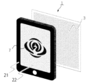
以下に、本発明の一実施の形態による潜像印刷物(1)について説明する。本実施の形態による潜像印刷物(1)は、目視で確認すると一見して単調な画線が一様に視認されるか、あるいは、一見すると可視模様が視認されるが、潜像模様を視認することはできず、スマートフォン等の潜像読取装置(21)で潜像印刷物(1)を読み取ると潜像模様(7)が出現するものである。 A latent image printed matter (1) according to one embodiment of the present invention will be described below. In the latent image printed material (1) according to the present embodiment, when visually confirmed, a seemingly monotonous image line is uniformly visually recognized, or a visible pattern is visually recognized at first glance, but the latent image pattern is visually recognized. The latent image pattern (7) appears when the latent image print (1) is read by a latent image reader (21) such as a smartphone.
(潜像印刷物)
図1に、本発明の一実施の形態による潜像印刷物(1)を示す。潜像印刷物(1)は、基材(2)上に潜像模様(7)を施した印刷模様(3)を有する。基材(2)は、印刷模様(3)を形成することができれば、紙、フィルム、紙をフィルムでコーティングした複合基材等が利用可能である。印刷模様(3)は、目視において模様として認識できるように、基材(2)とは異なる色を有している。
(latent image print)
FIG. 1 shows a latent image print (1) according to one embodiment of the present invention. A latent image print (1) has a printed pattern (3) obtained by applying a latent image pattern (7) on a substrate (2). As the substrate (2), a paper, a film, a composite substrate obtained by coating paper with a film, or the like can be used as long as the printed pattern (3) can be formed thereon. The printed pattern (3) has a color different from that of the substrate (2) so that it can be visually recognized as a pattern.
また、図1の拡大図に示すように、印刷模様(3)は後述にて説明する画線構成の最小単位である第1のユニット(4)、第2のユニット(5)及び第3のユニット(6)が複数配列して形成される。本実施の形態は、第1のユニット(4)、第2のユニット(5)及び第3のユニット(6)の3つのユニットで構成している例で説明するが、ユニットの種類は3つに限定されず、2種類あるいは4種類以上のユニットで構成してもよい。 Further, as shown in the enlarged view of FIG. 1, the printed pattern (3) consists of a first unit (4), a second unit (5), and a third unit, which are the minimum units of the image line structure, which will be described later. A plurality of units (6) are arranged and formed. The present embodiment will be described with an example configured with three units, a first unit (4), a second unit (5) and a third unit (6), but there are three types of units. , and may be composed of two or four or more types of units.
図2に、本実施の形態による潜像印刷物(1)を、例えば、スマートフォンに潜像模様(7)を可視化するアプリケーションをインストールした潜像読取装置(21)を使用して、観察した状態を示す。図2に示すように、印刷模様(3)は、潜像読取装置(21)のカメラ機能とアプリケーションによって潜像模様(7)として「鳳凰」が可視化されて、画面(22)に表示される。なお、潜像模様(7)は、記号、数字、イラスト、風景、顔模様等、階調の有無を含め、あらゆる模様を用いることができる。 FIG. 2 shows a state in which the latent image printed matter (1) according to the present embodiment is observed using, for example, a latent image reader (21) in which an application for visualizing the latent image pattern (7) is installed on a smartphone. show. As shown in FIG. 2, the printed pattern (3) is visualized as a latent image pattern (7) by the camera function of the latent image reader (21) and an application, and displayed on the screen (22). . As the latent image pattern (7), any pattern can be used, including symbols, numbers, illustrations, landscapes, facial patterns, and the like, including the presence or absence of gradation.
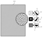
図3に、本実施の形態による潜像印刷物(1)における画線構成を示す。潜像印刷物(1)は、基材(2)の少なくとも一部に潜像模様(7)を備えた印刷模様(3)を有し、印刷模様(3)は、以下に示す複数のユニットが所定間隔で規則的に配置されて成る。 FIG. 3 shows the image line configuration in the latent image printed matter (1) according to the present embodiment. The latent image print (1) has a printed pattern (3) with a latent image pattern (7) on at least a portion of a substrate (2), the printed pattern (3) comprising a plurality of units shown below. They are arranged regularly at predetermined intervals.
(潜像画線)
本発明は、ユニットに潜像画線のみを有する構成であってよい。図3(a)に示された第1のユニット(4)は、潜像模様の構成要素としての潜像画線(31、32、33))が左上から右下への斜め線で形成され、図3(b)に示された第2のユニット(5)は、潜像画線(32)が右上から左下への斜め線で形成され、図3(c)に示された第3のユニット(6)は、潜像画線(33)が左中央から右中央への横線で形成されている。
(latent image line)
The present invention may be configured to have only latent image lines in the unit. In the first unit (4) shown in FIG. 3(a), the latent image lines (31, 32, 33) as components of the latent image pattern are formed by oblique lines from upper left to lower right. , the second unit (5) shown in FIG. 3(b), the latent image line (32) is formed by diagonal lines from the upper right to the lower left, and the third unit (5) shown in FIG. 3(c). In the unit (6), the latent image line (33) is formed by a horizontal line from left center to right center.
各ユニット(4、5、6)内に配置されている潜像画線(31)は、ユニット内における面積率が全て等しい。図3においては、図3(a)と図3(b)とは、二つともユニット(4、5)の一端から対角線の一端までの斜めの潜像画線(31、32)が配置されているため、長さ及び画線幅(V1、V2)はいずれも等しいことから、面積率は等しい。また、図3(c)の第3の潜像画線(33)については、第3のユニット(6)の横(水平)方向に配置されているため、長さは第1のユニット(4)の第1の潜像画線(31)及び第2のユニット(5)の第2の潜像画線(32)よりも短い。ただし、画線幅(V3)については、第1の潜像画線(31)の画線幅(V1)及び第2の潜像画線(32)の画線幅(V2)よりも太くなっており、面積率は、第3の潜像画線(33)も第1の潜像画線(31)及び第2の潜像画線(32)と等しくなっている。したがって、各潜像画線の長さ及び画線幅とを調整することにより、全てのユニットにおける潜像画線の面積率を等しく形成することができる。 All the latent image lines (31) arranged in each unit (4, 5, 6) have the same area ratio within the unit. In FIG. 3, in both FIGS. 3(a) and 3(b), oblique latent image lines (31, 32) are arranged from one end of the unit (4, 5) to one end of the diagonal line. Since the lengths and the image line widths (V1, V2) are equal, the area ratios are equal. Also, the third latent image line (33) in FIG. 3(c) is arranged in the lateral (horizontal) direction of the third unit (6), so its length is the same as that of the first unit (4 ) and the second latent image line (32) of the second unit (5). However, the image line width (V3) is thicker than the image line width (V1) of the first latent image line (31) and the image line width (V2) of the second latent image line (32). The area ratio of the third latent image line (33) is the same as that of the first latent image line (31) and the second latent image line (32). Therefore, by adjusting the length and width of each latent image line, the area ratio of the latent image lines in all units can be formed equally.
潜像画線の面積率については、図3では直線を対象として長さと画線幅による調整により、面積率を等しくする方法を説明したが、潜像画線は、直線のみに限定されるものではなく、後述するように、例えば「◎」、「〇」及び「×」のように形状を異ならせても良いため、大きさ及び画線幅を異ならせて面積率を等しくすることが可能である。 As for the area ratio of the latent image lines, a method of equalizing the area ratio by adjusting the length and the image line width for straight lines was explained in FIG. However, as will be described later, the shapes may be different, for example, “◎”, “〇” and “×”, so it is possible to equalize the area ratio by changing the size and line width. is.
図3においては、潜像画線の長さ及び画線幅が異なっていても面積率が等しい例で説明したが、全ての潜像画線を同じ形状及び大きさとし、配置角度のみ異ならせて各潜像画線(31、32、33)を形成すれば、面積率を全て等しくすることが可能である。 In FIG. 3, an example in which the area ratio is the same even if the length and width of the latent image lines are different has been described. By forming each latent image line (31, 32, 33), it is possible to make all the area ratios equal.
このように各ユニット内における潜像画線の面積率を等しくすることで、印刷模様(3)は濃度が一定となるため、目視で確認すると一見して単調な画線模様が視認され、潜像読取装置(21)において潜像模様(7)が可視化される潜像印刷物(1)となる。 By equalizing the area ratio of the latent image lines in each unit in this way, the printed pattern (3) has a constant density. The latent image pattern (7) becomes a latent image print (1) visualized in the image reading device (21).
本実施の形態においては、前述のとおり、3つのユニット(4、5、6)及び各ユニットに配置される3つの潜像画線(31、32、33)により潜像模様(7)が形成されている例で説明するが、本発明による潜像模様(7)は、後述する潜像読取装置(21)によって、カラー模様として確認可能とするため、少なくとも2色の色成分を有すればよいことから、異なる色成分にそれぞれ対応した2つの潜像画線を備えていればよい。 In this embodiment, as described above, the latent image pattern (7) is formed by the three units (4, 5, 6) and the three latent image lines (31, 32, 33) arranged in each unit. The latent image pattern (7) according to the present invention can be confirmed as a color pattern by a latent image reading device (21) described later, so that it has at least two color components. Since it is good, it suffices to have two latent image lines, each corresponding to a different color component.
この色成分に対応した潜像画線により形成される色成分模様は、あくまでも潜像模様(7)を形成する際の模様データ上及び潜像印刷物(1)から潜像模様(7)を読み取る際の潜像読取装置(21)内での模様データとしては存在するが、潜像印刷物(1)自体を目視で確認してもその存在を認識することはできない。 The color component pattern formed by the latent image lines corresponding to this color component is read from the pattern data and the latent image printed matter (1) when forming the latent image pattern (7). Although it exists as pattern data in the actual latent image reading device (21), its existence cannot be recognized even if the latent image printed matter (1) itself is visually confirmed.
以上のとおり、本発明における潜像模様(7)は、少なくとも2つの色成分模様(第1の色成分模様及び第2の色成分模様)を有しており、それぞれの色成分模様を構成するため、色成分模様に対応した少なくとも2つの潜像画線(第1の潜像画線及び第2の潜像画線)から成る。 As described above, the latent image pattern (7) in the present invention has at least two color component patterns (first color component pattern and second color component pattern). Therefore, it consists of at least two latent image lines (a first latent image line and a second latent image line) corresponding to the color component pattern.
なお、本発明における「色成分模様に対応した潜像画線」とは、例えば、形成する潜像模様(7)を色分解して、橙色と黒色とした場合、橙色を表す第1の色成分模様を形成するための潜像画線を第1の潜像画線とし、黒色を表す第2の色成分模様を形成するための潜像画線を第2の潜像画線とするものである。 In the present invention, the "latent image line corresponding to the color component pattern" is, for example, the first color representing orange when the latent image pattern (7) to be formed is color-separated into orange and black. A latent image line for forming a component pattern is defined as a first latent image line, and a latent image line for forming a second color component pattern representing black is defined as a second latent image line. is.
カラー模様として潜像模様(7)を形成するための最低色数である2色を例に説明したが、3色以上の場合についても同様に、形成する潜像模様を色分解した色成分模様に対応した潜像画線により潜像模様(7)は形成することとなる。3色以上とした場合には、フルカラー模様として潜像模様(7)を形成することが可能となる。この色成分模様については、潜像印刷物の作成方法において詳細を後述する。 Although two colors, which is the minimum number of colors for forming the latent image pattern (7) as a color pattern, has been described as an example, a color component pattern obtained by color-separating the latent image pattern to be formed is similarly applied to the case of three or more colors. The latent image pattern (7) is formed by the latent image lines corresponding to . When three or more colors are used, the latent image pattern (7) can be formed as a full-color pattern. This color component pattern will be described later in detail in the method of creating a latent image print.
また、本発明は、ユニットに潜像画線(31、32、33)に加えて、可視模様を形成する可視模様形成領域(41、42、43)を有していてもよい。図3(d)に示された第1のユニット(4)は、さらに潜像画線(31)より下側に、可視模様を形成するための画線面積が広がる可視模様形成領域(41)を有し、図3(e)に示された第2のユニット(5)は、さらに潜像画線(32)より下側に、可視模様を形成するための画線面積が広がる可視模様形成領域(42)を有し、図3(f)に示された第3のユニット(6)は、さらに潜像画線(33)より下側に可視模様を形成するための画線面積が広がる可視模様形成領域(43)を有している。なお、可視模様は、可視模様形成領域(41、42、43)だけではなく、潜像画線(31、32、33)の少なくとも一部を異なる色に置換して、置換した色を有する可視模様を形成してもよく、さらには、一本の潜像画線(31、32、33)の中で、一部を異なる色に置換して、可視模様を形成したり、これらを組み合わせたりしてもよい。以下、一例として、可視模様を、可視模様形成領域(41、42、43)で形成する構成として説明する。 The present invention may also have visible pattern forming areas (41, 42, 43) for forming visible patterns in addition to the latent image lines (31, 32, 33) in the unit. The first unit (4) shown in FIG. 3(d) further comprises a visible pattern forming area (41) below the latent image line (31) where the image line area for forming a visible pattern is widened. and a second unit (5) shown in FIG. A third unit (6), shown in FIG. 3(f), having an area (42) further extends the image area for forming the visible pattern below the latent image line (33). It has a visible patterned area (43). The visible pattern is formed by replacing not only the visible pattern forming areas (41, 42, 43) but also at least part of the latent image lines (31, 32, 33) with different colors. A pattern may be formed, and furthermore, in one latent image line (31, 32, 33), a part is replaced with a different color to form a visible pattern, or a combination thereof. You may Hereinafter, as an example, a configuration in which the visible pattern is formed in the visible pattern forming regions (41, 42, 43) will be described.
第1のユニット(4)、第2のユニット(5)及び第3のユニット(6)は、同一の形状と大きさを有し、縦横の寸法(u)は、0.18mmから0.50mmの範囲内にある。縦横の寸法(u)が0.50mmを超えると視認されやすく、潜像模様(7)の秘匿性が低くなり、0.18mmより小さいとプリンタ等による潜像画線の形成が困難となる。ただし、このユニットの寸法については、現状のプリンタの性能を考慮したものであり、将来に亘り、プリンタの性能が向上するに伴い、この範囲も適宜異なってくることは言うまでもなく、また、確認者の視力や視認角度による条件の差によっても異なるものではあるが、あくまでも例としての記載であり、本発明の技術的範囲を限定するものではない。 The first unit (4), the second unit (5) and the third unit (6) have the same shape and size, and the vertical and horizontal dimensions (u) are 0.18 mm to 0.50 mm. within the range of If the vertical and horizontal dimensions (u) exceed 0.50 mm, the latent image pattern (7) is likely to be visually recognized, and the confidentiality of the latent image pattern (7) becomes low. However, the dimensions of this unit take into consideration the performance of the current printer, and it goes without saying that this range will change as the performance of the printer improves in the future. Although it may differ depending on the difference in conditions due to visual acuity and viewing angle, it is only an example and does not limit the technical scope of the present invention.
また、第1のユニット(4)、第2のユニット(5)及び第3のユニット(6)にそれぞれ設けられた潜像画線(31、32、33)の画線幅(V1、V2、V3)は、ユニットの寸法(u)の1/5~1/10の範囲内が望ましい。例えば、ユニットの寸法(u)が0.423mmの場合、潜像画線(31、32、33)の画線幅(V1、V2、V3)は、0.040~0.085mmとなる。潜像画線(31、32、33)の画線幅(V1、V2、V3)がユニットの寸法(u)の1/5より太い場合は、潜像模様(7)が視認されやすくなる。潜像画線(31、32、33)の画線幅(V1、V2、V3)がユニットの寸法(u)の1/10より細い場合は、潜像画線(31、32、33)を読み取って潜像模様(7)を再現することが困難となる。 Further, the image line widths (V1, V2, V3) is preferably in the range of 1/5 to 1/10 of the dimension (u) of the unit. For example, when the dimension (u) of the unit is 0.423 mm, the image line widths (V1, V2, V3) of the latent image lines (31, 32, 33) are 0.040 to 0.085 mm. When the image line widths (V1, V2, V3) of the latent image lines (31, 32, 33) are thicker than 1/5 of the unit dimension (u), the latent image pattern (7) is easily visible. If the image line widths (V1, V2, V3) of the latent image lines (31, 32, 33) are thinner than 1/10 of the unit dimension (u), the latent image lines (31, 32, 33) are It becomes difficult to read and reproduce the latent image pattern (7).
図4(a)に示された第1のユニット(4)の例では、潜像画線(31)の両端部分がユニット内の端まで形成されている。図4(b)に示された第1のユニット(4)の例では、潜像画線(31)がユニット内の一方の端の途中から他方の端の途中まで配置されており、端までは形成されていない。このように、ユニット内において潜像画線がユニットの端まで形成されていてもよく、形成されていなくてもよい。 In the example of the first unit (4) shown in FIG. 4(a), both end portions of the latent image line (31) are formed to the ends within the unit. In the example of the first unit (4) shown in FIG. 4(b), the latent image line (31) is arranged from the middle of one end in the unit to the middle of the other end, is not formed. Thus, the latent image line may or may not be formed to the end of the unit within the unit.
(可視模様形成領域)
本発明における潜像印刷物(1)は、前述したように、目視で確認した際に視認できる可視模様を形成することができる。図5(a)に、第1のユニット(4)内において、潜像画線(31)に隣接して可視模様を形成する可視模様形成領域(41)に、形成する可視模様の任意の階調濃度に対応した濃度を形成した状態を示す。
(Visible pattern forming area)
As described above, the latent image printed matter (1) in the present invention can form a visible pattern that can be visually recognized. In FIG. 5( a ), in the first unit ( 4 ), the visible pattern forming area ( 41 ) forming the visible pattern adjacent to the latent image line ( 31 ) is formed on any level of the visible pattern. It shows a state in which a density corresponding to the tonal density is formed.
例えば、図5(b)は、可視模様形成領域(41)の濃度が0%であるときの状態を示す。この場合は、潜像画線(31)のみが形成されており、可視模様を形成するための可視模様形成領域(41)は形成されない。具体的には、トーンカーブで濃度10%に変換され、10%に相当する潜像画線(31)のみが形成される。なお、前述した可視模様形成領域(31)の濃度が0%であるとき、トーンカーブで変換される濃度10%の数値は、あくまで一例であり、ユニットに潜像画線(31)のみ形成可能であれば、これに限定されない。 For example, FIG. 5(b) shows the state when the density of the visible pattern forming area (41) is 0%. In this case, only the latent image lines (31) are formed, and the visible pattern forming area (41) for forming the visible pattern is not formed. Specifically, the density is converted to 10% by the tone curve, and only the latent image line (31) corresponding to 10% is formed. When the density of the visible pattern forming area (31) is 0%, the numerical value of the density of 10% converted by the tone curve is just an example, and only the latent image line (31) can be formed on the unit. If so, it is not limited to this.
図5(c)に、可視模様形成領域(41)の濃度が50%であるときの状態を示す。具体的には、トーンカーブで濃度24%に変換され、10%に相当する潜像画線(31)に加えて、14%に相当する可視要素が可視模様形成領域(41)に形成される。 FIG. 5(c) shows the state when the density of the visible pattern forming area (41) is 50%. Specifically, the density is converted to 24% by the tone curve, and in addition to the latent image line (31) corresponding to 10%, the visible element corresponding to 14% is formed in the visible pattern forming area (41). .
また、図5(d)に、可視模様形成領域(41)の濃度が100%であるときの状態を示す。具体的には、トーンカーブで濃度38%に変換され、10%に相当する潜像画線(31)に加えて、28%に相当する可視要素が可視模様形成領域(41)に形成される。 FIG. 5(d) shows the state when the density of the visible pattern forming area (41) is 100%. Specifically, the density is converted to 38% by the tone curve, and in addition to the latent image line (31) corresponding to 10%, the visible element corresponding to 28% is formed in the visible pattern forming area (41). .
なお、図5(c)における可視模様形成領域(31)の濃度が50%であるときにトーンカーブで変換される濃度24%の数値、及び図5(d)における可視模様形成領域(31)の濃度が100%であるときにトーンカーブで変換される濃度38%の数値は、あくまで一例であり、ユニットにおいて潜像画線(31)及び可視模様形成領域(41)に所望する濃度の可視模様を形成できればこれに限定されない。本発明における以降の説明についても同様である。 Note that the numerical value of the density of 24% converted by the tone curve when the density of the visible pattern forming area (31) in FIG. 5(c) is 50%, and the visible pattern forming area (31) in FIG. 5(d) The numerical value of 38% density converted by the tone curve when the density of 100% is only an example, and the desired density for the latent image line (31) and the visible pattern forming area (41) in the unit It is not limited to this as long as a pattern can be formed. The same applies to the subsequent description of the present invention.
前述と同様に、図6(a)に、第2のユニット(5)内において、潜像画線(32)に隣接して可視模様を形成する可視模様形成領域(42)に、形成する可視模様の任意の階調濃度に対応した濃度を形成した状態を示す。 As before, in FIG. 6(a), in the second unit (5), a visible pattern forming area (42) forming a visible pattern adjacent to the latent image line (32) forms a visible pattern forming area (42). It shows the state in which the density corresponding to the arbitrary gradation density of the pattern is formed.
図6(b)に、可視模様形成領域(42)の濃度が0%であるときの状態を示す。この場合は、潜像画線(32)のみが形成されており、可視模様を形成するための可視模様形成領域(42)は形成されない。具体的には、トーンカーブで濃度10%に変換され、10%に相当する潜像画線(32)のみが形成される。 FIG. 6(b) shows the state when the density of the visible pattern forming area (42) is 0%. In this case, only the latent image lines (32) are formed, and the visible pattern forming area (42) for forming the visible pattern is not formed. Specifically, the density is converted to 10% by the tone curve, and only the latent image line (32) corresponding to 10% is formed.
また、図6(c)に、可視模様形成領域(42)の濃度が50%であるときの状態を示す。具体的には、トーンカーブで濃度24%に変換され、10%に相当する潜像画線(32)に加えて、14%に相当する可視要素が可視模様形成領域(42)に形成される。 FIG. 6(c) shows the state when the density of the visible pattern forming area (42) is 50%. Specifically, the density is converted to 24% by the tone curve, and in addition to the latent image line (32) corresponding to 10%, the visible element corresponding to 14% is formed in the visible pattern forming area (42). .
次に、図6(d)に、可視模様形成領域(42)の濃度が100%であるときの状態を示す。具体的には、トーンカーブで濃度38%に変換され、10%に相当する潜像画線(32)に加えて、28%に相当する可視要素が可視模様形成領域(42)に形成される。 Next, FIG. 6(d) shows the state when the density of the visible pattern forming area (42) is 100%. Specifically, the density is converted to 38% by the tone curve, and in addition to the latent image line (32) corresponding to 10%, the visible element corresponding to 28% is formed in the visible pattern forming area (42). .
さらに、図7(a)に、第3のユニット(6)内において、潜像画線(33)に隣接して可視模様を形成する可視模様形成領域(43)に、形成する可視模様の任意の階調濃度に対応した濃度を形成した状態を示す。 Further, in FIG. 7(a), in the third unit (6), any visible pattern to be formed in the visible pattern forming area (43) forming the visible pattern adjacent to the latent image line (33). 2 shows a state in which densities corresponding to the gradation densities of are formed.
図7(b)に、可視模様形成領域(43)の濃度が0%であるときの状態を示す。この場合は、潜像画線(33)のみが形成されており、可視模様を形成するための可視模様形成領域(43)は形成されない。具体的には、トーンカーブで濃度10%に変換され、10%に相当する潜像画線33のみが形成される。
FIG. 7(b) shows the state when the density of the visible pattern forming area (43) is 0%. In this case, only the latent image lines (33) are formed, and the visible pattern forming area (43) for forming the visible pattern is not formed. Specifically, the density is converted to 10% by the tone curve, and only the
また、図7(c)に、可視模様形成領域(43)の濃度が50%であるときの状態を示す。具体的には、トーンカーブで濃度24%に変換され、10%に相当する潜像画線(33)に加えて、14%に相当する可視要素が可視模様形成領域(43)に形成される。 FIG. 7(c) shows the state when the density of the visible pattern forming area (43) is 50%. Specifically, the density is converted to 24% by the tone curve, and in addition to the latent image line (33) corresponding to 10%, the visible element corresponding to 14% is formed in the visible pattern forming area (43). .
次に、図7(d)に、可視模様形成領域(43)の濃度が100%であるときの状態を示す。具体的には、トーンカーブで濃度38%に変換され、10%に相当する潜像画線(33)に加えて、28%に相当する可視要素が可視模様形成領域(43)に形成される。 Next, FIG. 7(d) shows the state when the density of the visible pattern forming area (43) is 100%. Specifically, the density is converted to 38% by the tone curve, and in addition to the latent image line (33) corresponding to 10%, the visible element corresponding to 28% is formed in the visible pattern forming area (43). .
このように、例えば、第1のユニット(4)において、可視模様の階調濃度の増加に伴って、潜像画線(31)に隣接した可視模様形成領域(41)の画線面積率が増加し可視要素の面積が増加する。なお、前述した例では、潜像画線(31)の下側に可視模様形成領域(41)を設けている。しかし、可視模様形成領域(41)の位置には限定されず、ユニット内であれば、ユニット内における潜像画線が形成されていない領域や、さらには、前述したとおり、可視模様形成領域(41)だけではなく、複数配置した潜像画線(31)のうち、少なくとも一部を異なる色に置換して、置換した色を有する可視模様を形成してもよく、さらには、一本の潜像画線(31)中で、一部を異なる色に置換して、可視模様を形成したり、これらを組み合わせたりしてもよい。 Thus, for example, in the first unit (4), as the gradation density of the visible pattern increases, the image area ratio of the visible pattern forming area (41) adjacent to the latent image line (31) increases. Increase to increase the area of visible elements. In the above example, the visible pattern forming area (41) is provided below the latent image line (31). However, it is not limited to the position of the visible pattern forming area (41). 41), at least some of the arranged latent image lines (31) may be replaced with different colors to form a visible pattern having the replaced colors. Within the latent image lines (31), portions may be replaced with different colors to form visible patterns, or combinations thereof.
図5(a)、図6(a)、図7(a)を用いて前述した例では、可視模様形成領域(41、42、43)が潜像画線(31、32、33)を始点として徐々に拡大し、かつ、濃度が徐々に潜像画線(31、32、33)から離れるに従って低下するように階調性を伴って形成されている。これに対し、後述の例では、可視模様形成領域(41、42、43)が潜像画線(31、32、33)を境界として一方の領域又は両方の領域に、可視模様の階調濃度に応じて均一な画線面積率で形成されている。 In the examples described above with reference to FIGS. 5(a), 6(a), and 7(a), the visible pattern forming areas (41, 42, 43) start from the latent image lines (31, 32, 33). , and is formed with gradation such that the density gradually decreases as the distance from the latent image lines (31, 32, 33) increases. On the other hand, in the examples described later, the visible pattern forming regions (41, 42, 43) are divided into one region or both regions with the latent image lines (31, 32, 33) as boundaries, and the gradation density of the visible pattern is It is formed with a uniform image line area ratio according to the
可視模様形成領域(41、42、43)が潜像画線(31、32、33)を境界として2つの領域のうち一方の領域に、可視模様の階調濃度に応じて均一な画線面積率で形成される例を説明する。 The visible pattern forming areas (41, 42, 43) are formed in one of the two areas with the latent image lines (31, 32, 33) as boundaries, and a uniform image area corresponding to the gradation density of the visible pattern. An example formed by a rate is explained.
図8(a)に、第1のユニット(4)内において、潜像画線(31)に隣接して可視模様を形成する可視模様形成領域(41)に、形成する可視模様の階調濃度に対応した濃度を形成することを示す。 FIG. 8(a) shows the gradation density of the visible pattern formed in the visible pattern forming area (41) forming the visible pattern adjacent to the latent image line (31) in the first unit (4). to form a concentration corresponding to
図8(b)に、可視模様形成領域(41)の濃度が0%であるときの状態を示す。この場合は、潜像画線(31)のみが形成されており、可視模様を形成するための可視要素は形成されない。具体的には、トーンカーブで濃度10%に変換され、均一な10%の濃度の潜像画線(31)のみが形成される。 FIG. 8(b) shows the state when the density of the visible pattern forming area (41) is 0%. In this case only the latent image lines (31) are formed and no visible elements are formed to form the visible pattern. Specifically, the density is converted to 10% by the tone curve, and only latent image lines (31) with a uniform density of 10% are formed.
また、図8(c)に、可視模様形成領域(41)の濃度が50%であるときの状態を示す。具体的には、トーンカーブで濃度24%に変換され、10%に相当する潜像画線(31)に加えて、均一な14%の濃度の可視要素が可視模様形成領域(41)に形成される。 FIG. 8(c) shows the state when the density of the visible pattern forming area (41) is 50%. Specifically, in addition to the latent image lines (31) corresponding to 10%, which are converted to a density of 24% by the tone curve, visible elements with a uniform density of 14% are formed in the visible pattern forming area (41). be done.
次に、図8(d)に、可視模様形成領域(41)の濃度が100%であるときの状態を示す。具体的には、トーンカーブで濃度38%に変換され、10%に相当する潜像画線(31)に加えて、均一な28%の濃度の可視要素が可視模様形成領域(41)に形成される。 Next, FIG. 8(d) shows the state when the density of the visible pattern forming area (41) is 100%. Specifically, in addition to the latent image line (31) corresponding to 10%, which is converted to a density of 38% by the tone curve, a uniform 28% density visible element is formed in the visible pattern forming area (41). be done.
図9(a)に、第2のユニット(5)内において、潜像画線(32)に隣接して可視模様を形成する可視模様形成領域(42)に、形成する可視模様の階調濃度に対応した濃度を形成することを示す。 FIG. 9(a) shows the gradation density of the visible pattern formed in the visible pattern forming area (42) forming the visible pattern adjacent to the latent image line (32) in the second unit (5). to form a concentration corresponding to
図9(b)に、可視模様形成領域(42)の濃度が0%であるときの状態を示す。この場合は、潜像画線(32)のみが形成されており、可視模様を形成するための可視要素は形成されない。具体的には、トーンカーブで濃度10%に変換され、均一な10%の濃度の潜像画線(32)のみが形成される。 FIG. 9(b) shows the state when the density of the visible pattern forming area (42) is 0%. In this case only the latent image lines (32) are formed and no visible elements are formed to form the visible pattern. Specifically, the density is converted to 10% by the tone curve, and only latent image lines (32) with a uniform density of 10% are formed.
また、図9(c)に、可視模様形成領域(42)の濃度が50%であるときの状態を示す。具体的には、トーンカーブで濃度24%に変換され、10%に相当する潜像画線(32)に加えて、均一な14%の濃度の可視要素が可視模様形成領域(42)に形成される。 FIG. 9(c) shows the state when the density of the visible pattern forming area (42) is 50%. Specifically, in addition to the latent image lines (32) that are converted to 24% density by the tone curve and correspond to 10%, a uniform 14% density visible element is formed in the visible pattern forming area (42). be done.
次に、図9(d)に、可視模様形成領域(42)の濃度が100%であるときの状態を示す。具体的には、トーンカーブで濃度38%に変換され、10%に相当する潜像画線(32)に加えて、均一な28%の濃度の可視要素が可視模様形成領域(42)に形成される。 Next, FIG. 9(d) shows the state when the density of the visible pattern forming area (42) is 100%. Specifically, in addition to the latent image lines (32) that are converted to 38% density by the tone curve and correspond to 10%, a uniform 28% density visible element is formed in the visible pattern forming area (42). be done.
図10(a)に、第3のユニット(6)内において、潜像画線(33)に隣接して可視模様を形成する可視模様形成領域(43)に、形成する可視模様の階調濃度に対応した濃度を形成することを示す。 FIG. 10(a) shows the gradation density of the visible pattern formed in the visible pattern forming area (43) forming the visible pattern adjacent to the latent image line (33) in the third unit (6). to form a concentration corresponding to
図10(b)に、可視模様形成領域(43)の濃度が0%であるときの状態を示す。この場合は、潜像画線(33)のみが形成されており、可視模様を形成するための可視要素は形成されない。具体的には、トーンカーブで濃度10%に変換され、均一な10%の濃度の潜像画線(33)のみが形成される。 FIG. 10(b) shows the state when the density of the visible pattern forming area (43) is 0%. In this case only the latent image lines (33) are formed and no visible elements are formed to form the visible pattern. Specifically, the density is converted to 10% by the tone curve, and only latent image lines (33) with a uniform density of 10% are formed.
また、図10(c)に、可視模様形成領域(43)の濃度が50%であるときの状態を示す。具体的には、トーンカーブで濃度24%に変換され、10%に相当する潜像画線(33)に加えて、均一な14%の濃度の可視要素が可視模様形成領域(43)に形成される。 Further, FIG. 10(c) shows the state when the density of the visible pattern forming area (43) is 50%. Specifically, in addition to the latent image line (33) corresponding to 10%, which is converted to a density of 24% by the tone curve, a uniform 14% density visible element is formed in the visible pattern forming area (43). be done.
次に、図10(d)に、可視模様形成領域(43)の濃度が100%であるときの状態を示す。具体的には、トーンカーブで濃度38%に変換され、10%に相当する潜像画線(33)に加えて、均一な28%の濃度の可視要素が可視模様形成領域(43)に形成される。 Next, FIG. 10(d) shows the state when the density of the visible pattern forming area (43) is 100%. Specifically, in addition to the latent image line (33) corresponding to 10%, which is converted to a density of 38% by the tone curve, a uniform 28% density visible element is formed in the visible pattern forming area (43). be done.
次に、可視模様形成領域(41、42、43)が潜像画線(31、32、33)を境界とした二つの領域に、形成する可視模様の階調濃度に応じて均一な画線面積率で形成される例を説明する。 Next, the visible pattern forming regions (41, 42, 43) are formed in two regions bounded by the latent image lines (31, 32, 33), and uniform image lines are formed according to the gradation density of the visible pattern to be formed. An example formed with an area ratio will be described.
図11(a)に、第1のユニット(4)内において、潜像画線(31)を境界とした二つの可視模様形成領域(41)に、形成する可視模様の階調濃度に対応した濃度を形成することを示す。 In FIG. 11(a), in the first unit (4), two visible pattern forming regions (41) with the latent image line (31) as a boundary correspond to the gradation density of the visible pattern to be formed. It shows to form a concentration.
図11(b)に、可視模様形成領域(41)の濃度が0%であるときの状態を示す。この場合は、潜像画線(31)のみが形成されており、可視模様を形成するための可視要素は形成されない。具体的には、トーンカーブで濃度10%に変換され、均一な10%の濃度の潜像画線(31)のみが形成される。 FIG. 11(b) shows the state when the density of the visible pattern forming area (41) is 0%. In this case only the latent image lines (31) are formed and no visible elements are formed to form the visible pattern. Specifically, the density is converted to 10% by the tone curve, and only latent image lines (31) with a uniform density of 10% are formed.
また、図11(c)に、可視模様形成領域(41)の濃度が50%であるときの状態を示す。具体的には、トーンカーブで濃度24%に変換され、10%に相当する潜像画線(31)に加えて、均一な14%の濃度の可視要素が二つの可視模様形成領域(41)に形成される。 FIG. 11(c) shows the state when the density of the visible pattern forming area (41) is 50%. Specifically, in addition to the latent image line (31) which is converted to 24% density by the tone curve and corresponds to 10%, the uniform 14% density visible element is two visible pattern forming areas (41). formed in
次に、図11(d)に、可視模様形成領域(41)の濃度が100%であるときの状態を示す。具体的には、トーンカーブで濃度38%に変換され、10%に相当する潜像画線(31)に加えて、均一な28%の濃度の可視要素が二つの可視模様形成領域(41)に形成される。 Next, FIG. 11(d) shows the state when the density of the visible pattern forming area (41) is 100%. Specifically, in addition to the latent image line (31) which is converted to 38% density by the tone curve and corresponds to 10%, the uniform 28% density visible element is two visible pattern forming areas (41). formed in
また、図12(a)から(d)に示すように、第2のユニット(5)に潜像画線(32)を境界として、可視要素が二つの可視模様形成領域(42)に形成される場合及び図13(a)から(d)に示すように、第3のユニット(6)に潜像画線(33)を境界として、可視要素が二つの可視模様形成領域(43)に形成される場合も同様である。 Also, as shown in FIGS. 12(a) to (d), visible elements are formed in two visible pattern forming areas (42) with the latent image line (32) as a boundary in the second unit (5). 13(a) to 13(d), visible elements are formed in two visible pattern forming areas (43) with the latent image line (33) as a boundary in the third unit (6). The same is true when
(画素)
ここで、図14(a)に、10画素×10画素で構成された第1のユニット(4)内において、潜像画線(31)に隣接して可視模様を形成する可視模様形成領域(41)に、形成する可視模様の階調濃度に対応した濃度を形成した状態を示す。
(pixel)
Here, in FIG. 14(a), a visible pattern forming area ( 41) shows a state in which the density corresponding to the gradation density of the visible pattern to be formed is formed.
図14(b)に、可視模様形成領域(41)の濃度が0%であるときの状態を示す。この場合は、潜像画線(31)のみが形成されており、可視模様を形成するための可視要素は形成されない。具体的には、トーンカーブで濃度10%に変換され、10%に相当する潜像画線(31)のみが形成される。 FIG. 14(b) shows the state when the density of the visible pattern forming area (41) is 0%. In this case only the latent image lines (31) are formed and no visible elements are formed to form the visible pattern. Specifically, the density is converted to 10% by the tone curve, and only the latent image line (31) corresponding to 10% is formed.
また、図14(c)に、可視模様形成領域(41)の濃度が50%であるときの状態を示す。具体的には、トーンカーブで濃度24%に変換され、10%に相当する潜像画線(31)に加えて、14%に相当する可視要素が可視模様形成領域(41)に形成される。 FIG. 14(c) shows the state when the density of the visible pattern forming area (41) is 50%. Specifically, the density is converted to 24% by the tone curve, and in addition to the latent image line (31) corresponding to 10%, the visible element corresponding to 14% is formed in the visible pattern forming area (41). .
次に、図14(d)に、可視模様形成領域(41)の濃度が100%であるときの状態を示す。具体的には、トーンカーブで濃度38%に変換され、10%に相当する潜像画線(31)に加えて、28%に相当する可視要素が可視模様形成領域(41)に形成される。 Next, FIG. 14(d) shows the state when the density of the visible pattern forming area (41) is 100%. Specifically, the density is converted to 38% by the tone curve, and in addition to the latent image line (31) corresponding to 10%, the visible element corresponding to 28% is formed in the visible pattern forming area (41). .
図15(a)に、10画素×10画素で構成された第2のユニット(5)内において、潜像画線(32)に隣接して可視模様を形成する可視模様形成領域(42)に、可視模様の階調濃度に対応した濃度を形成した状態を示す。 In FIG. 15(a), in the visible pattern forming area (42) forming the visible pattern adjacent to the latent image line (32) in the second unit (5) composed of 10 pixels×10 pixels, , shows a state in which a density corresponding to the gradation density of the visible pattern is formed.
図15(b)に、可視模様形成領域(42)の濃度が0%であるときの状態を示す。この場合は、潜像画線(32)のみが形成されており、可視模様を形成するための可視要素は形成されない。具体的には、トーンカーブで濃度10%に変換され、10%に相当する潜像画線(32)のみが形成される。 FIG. 15(b) shows the state when the density of the visible pattern forming area (42) is 0%. In this case only the latent image lines (32) are formed and no visible elements are formed to form the visible pattern. Specifically, the density is converted to 10% by the tone curve, and only the latent image line (32) corresponding to 10% is formed.
また、図15(c)に、可視模様形成領域(42)の濃度が50%であるときの状態を示す。具体的には、トーンカーブで濃度24%に変換され、10%に相当する潜像画線(32)に加えて、14%に相当する可視要素が可視模様形成領域(42)に形成される。 FIG. 15(c) shows the state when the density of the visible pattern forming area (42) is 50%. Specifically, the density is converted to 24% by the tone curve, and in addition to the latent image line (32) corresponding to 10%, the visible element corresponding to 14% is formed in the visible pattern forming area (42). .
次に、図15(d)に、可視模様形成領域(42)の濃度が100%であるときの状態を示す。具体的には、トーンカーブで濃度38%に変換され、10%に相当する潜像画線(32)に加えて、28%に相当する可視要素が可視模様形成領域(42)に形成される。 Next, FIG. 15(d) shows the state when the density of the visible pattern forming area (42) is 100%. Specifically, the density is converted to 38% by the tone curve, and in addition to the latent image line (32) corresponding to 10%, the visible element corresponding to 28% is formed in the visible pattern forming area (42). .
図16(a)に、10画素×10画素で構成された第3のユニット(6)内において、潜像画線(33)に隣接して可視模様を形成する可視模様形成領域(43)に、形成する可視模様の階調濃度に対応した濃度を形成した状態を示す。 In FIG. 16(a), in the visible pattern forming area (43) forming the visible pattern adjacent to the latent image line (33) in the third unit (6) composed of 10 pixels×10 pixels, , shows a state in which a density corresponding to the gradation density of the visible pattern to be formed is formed.
図16(b)に、可視模様形成領域(43)の濃度が0%であるときの状態を示す。この場合は、潜像画線(33)のみが形成されており、可視模様を形成するための可視要素は形成されない。具体的には、トーンカーブで濃度10%に変換され、10%に相当する潜像画線(33)のみが形成される。 FIG. 16(b) shows the state when the density of the visible pattern forming area (43) is 0%. In this case only the latent image lines (33) are formed and no visible elements are formed to form the visible pattern. Specifically, the density is converted to 10% by the tone curve, and only the latent image line (33) corresponding to 10% is formed.
また、図16(c)に、可視模様形成領域(43)の濃度が50%であるときの状態を示す。具体的には、トーンカーブで濃度24%に変換され、10%に相当する潜像画線(33)に加えて、14%に相当する可視要素が可視模様形成領域(43)に形成される。 FIG. 16(c) shows the state when the density of the visible pattern forming area (43) is 50%. Specifically, the density is converted to 24% by the tone curve, and in addition to the latent image line (33) corresponding to 10%, the visible element corresponding to 14% is formed in the visible pattern forming area (43). .
次に、図16(d)に、可視模様形成領域(43)の濃度が100%であるときの状態を示す。具体的には、トーンカーブで濃度38%に変換され、10%に相当する潜像画線(33)に加えて、28%に相当する可視要素が可視模様形成領域(43)に形成される。 Next, FIG. 16(d) shows the state when the density of the visible pattern forming area (43) is 100%. Specifically, the density is converted to 38% by the tone curve, and in addition to the latent image line (33) corresponding to 10%, the visible element corresponding to 28% is formed in the visible pattern forming area (43). .
なお、ユニットを縦横ともに3画素以上で構成することが可能である。しかしながら、第1のユニット(4)、第2のユニット(5)及び第3のユニット(6)をプリンタにより出力する場合は、後述するように、プリンタの描画性能を考慮して縦横ともに5画素以上で構成するのが望ましい。この5画素を換算すると、出力解像度が600dpiのプリンタでは、寸法(u)は、約0.21mmとなり、出力解像度が720dpiのプリンタでは、寸法(u)は、約0.18mmとなる。 It should be noted that it is possible to configure a unit with three or more pixels in both the vertical and horizontal directions. However, when the first unit (4), the second unit (5) and the third unit (6) are output by a printer, as will be described later, taking into consideration the drawing performance of the printer, 5 pixels in both vertical and horizontal directions are required. It is desirable to configure as above. When these five pixels are converted, the dimension (u) is about 0.21 mm for a printer with an output resolution of 600 dpi, and the dimension (u) is about 0.18 mm for a printer with an output resolution of 720 dpi.
また、同実施の形態による潜像印刷物(1)は、秘匿性の高い潜像模様(7)の形成を意図するものである。このため、人の近見視力において、潜像画線が1つ1つの画線として認識されないことが望ましい。例えば、図17(a)に示すように、各々のユニットが小さければ、近見視力では潜像画線が認識されずに一様の濃度として観察されるが、図17(b)に示すように、各々のユニットが大きいと、画線として観察されることとなる。潜像印刷物(1)の観察条件にもよるが、ユニットの縦横の寸法(u)が0.50mmを超えると、近見視力では画線として認識されやすい傾向にある。このことから、寸法(u)は、0.50mm以下であることが望ましい。 Further, the latent image printed matter (1) according to the embodiment is intended to form a latent image pattern (7) with high secrecy. Therefore, it is desirable that the latent image lines are not recognized as individual lines in human near vision. For example, as shown in FIG. 17(a), if each unit is small, the latent image line is not recognized in near vision and is observed as a uniform density, but as shown in FIG. 17(b). Moreover, if each unit is large, it will be observed as a streak. Although it depends on the observation conditions of the latent image printed matter (1), when the vertical and horizontal dimensions (u) of the unit exceed 0.50 mm, it tends to be recognized as an image line with near vision. Therefore, it is desirable that the dimension (u) is 0.50 mm or less.
(ユニット形状)
本実施の形態による潜像印刷物(1)では、ユニットの形状が正方形である場合を例にとり説明する。しかしながら、本発明におけるユニットの形状は、図18(a)から(c)に示すような縦の寸法(u)と横の寸法(w)とが異なる長方形であってもよく、あるいは図18(d)から(f)に示すような六角形であってもよい。なお、図18(a)から(f)に示されたユニットでは、潜像画線(31、32、33)のみが形成され、可視模様形成領域は形成されていない場合を示している。また、ユニット内の潜像画線の端部は、前述したように、ユニットの端まで形成されていてもよく、形成されていなくてもよい。
(unit shape)
In the case of the latent image printed matter (1) according to the present embodiment, the case where the shape of the unit is a square will be described as an example. However, the shape of the unit in the present invention may be a rectangle with different vertical dimension (u) and horizontal dimension (w) as shown in FIGS. It may be hexagonal as shown in d) to (f). Note that the units shown in FIGS. 18A to 18F show the case where only the latent image lines (31, 32, 33) are formed and no visible pattern forming area is formed. Further, the end of the latent image line in the unit may or may not be formed to the end of the unit as described above.
図19、図20及び図21のそれぞれに、印刷模様(3)における各々のユニットの配列の例を示す。図19(a)に示すように、複数のユニットをマトリクス状に隙間なく配置してもよい。図19(b)に、マトリクス状に配置されたユニットに潜像画線(31、32、33)を形成した状態を示す。また図20(a)に示すように、複数のユニットを水平方向にレンガ状に隙間なく配置してもよい。この場合は、水平方向の配列に対して垂直方向の位相がずれた状態にある。図20(b)に、レンガ状に配置されたユニットに潜像画線(31、32、33)を形成した状態を示す。さらに図21(a)に示すように、複数のユニットを垂直方向にレンガ状に隙間なく配置してもよい。この場合は、垂直方向の配列に対して水平方向の位相がずれた状態にある。図21(b)に、レンガ状に配置されたユニットに潜像画線(31、32、33)を形成した状態を示す。また、ユニットの形状が図18(d)から(f)に示すような六角形である場合、複数のユニットをハニカム状に隙間なく配置することができる(図示せず)。 19, 20 and 21 each show an example of arrangement of each unit in the print pattern (3). As shown in FIG. 19A, a plurality of units may be arranged in a matrix without gaps. FIG. 19(b) shows a state in which latent image lines (31, 32, 33) are formed on units arranged in a matrix. Alternatively, as shown in FIG. 20(a), a plurality of units may be horizontally arranged in a brick-like manner without gaps. In this case, the phases in the vertical direction are out of phase with respect to the arrangement in the horizontal direction. FIG. 20(b) shows a state in which the latent image lines (31, 32, 33) are formed on the units arranged in a brick shape. Furthermore, as shown in FIG. 21(a), a plurality of units may be arranged vertically in a brick-like manner without gaps. In this case, the phases in the horizontal direction are out of phase with respect to the arrangement in the vertical direction. FIG. 21(b) shows a state in which the latent image lines (31, 32, 33) are formed on the units arranged in a brick shape. Moreover, when the shape of the unit is hexagonal as shown in FIGS.
(潜像模様作成フロー)
次に、本発明の一実施の形態による潜像印刷物(1)の作成方法について説明する。
図22に、本発明の一実施の形態による潜像印刷物(1)の作成方法における潜像模様作成フロー(ステップ1からステップ4)と、可視模様作成フロー(ステップ5)とを示す。
(Latent image pattern creation flow)
Next, a method for creating a latent image printed matter (1) according to one embodiment of the present invention will be described.
FIG. 22 shows a latent image pattern creation flow (
まず、本実施の形態による潜像印刷物(1)の作成方法における潜像模様作成フローについて説明する。図22及び図23に示すように、ステップ1として、潜像模様(7)の基模様データ(51)を用意し、図示されないコンピュータ等の装置に入力された基模様データ(51)を色分解する。なお、潜像模様(7)では、フルカラーの階調模様とした。
First, the latent image pattern forming flow in the method for forming the latent image printed material (1) according to the present embodiment will be described. As shown in FIGS. 22 and 23, in
例えば、基模様データ(51)として、ICメモリ等の記憶装置に記憶されたフルカラーの階調模様である、顔模様の24bitRGB模様データ(51)を用意する。本実施の形態では、図22及び図23に示すように顔模様データを用いているが、顔模様には限定されず、記号、数字、イラスト、風景等、あらゆる模様を用いることができる。 For example, as the base pattern data (51), 24-bit RGB pattern data (51) of a face pattern, which is a full-color gradation pattern stored in a storage device such as an IC memory, is prepared. In the present embodiment, facial pattern data are used as shown in FIGS. 22 and 23, but not limited to facial patterns, and any patterns such as symbols, numbers, illustrations, landscapes, etc. can be used.
また、本実施の形態では、一例として、基模様データ(51)を特色分解により橙色成分模様データ(61)と黒色成分模様データ(62)とに分解している。しかしながら、特色分解には限定されず、RGB色分解やCMY色分解等、任意の複数の色に分解することができる。 Further, in the present embodiment, as an example, the base pattern data (51) is separated into orange component pattern data (61) and black component pattern data (62) by special color separation. However, it is not limited to special color separation, and can be separated into arbitrary plural colors such as RGB color separation and CMY color separation.
図22及び図24に示すように、ステップ2として、ステップ1で得られた橙色成分模様データ(61)及び黒色成分模様データ(62)を、画像解像度60dpiに変換し、更に誤差拡散ディザにより2階調化した橙色成分階調模様データ(71)と黒色成分階調模様データ(72)とを生成する。これにより、橙色成分階調模様データ(71)と黒色成分階調模様データ(72)は、それぞれ8bitから1bitに変換される。なお、この画像解像度を60dpiに変換する理由は、ステップ4において後述する。また、変換する画像解像度については、比較的粗い解像度に変換できればよく、60dpiには限定されない。
As shown in FIGS. 22 and 24, in
本実施の形態では、2階調化した橙色成分階調模様データ(71)と黒色成分階調模様データ(72)とを生成するために誤差拡散ディザを用いているが、これは、図1又は図2に示すように、印刷物上に形成されている一様な印刷模様(3)とするために望ましい手段として選択したものであり、色成分階調模様データを作成するための二値化処理が出来ればこれに限定はしない。 In the present embodiment, error diffusion dither is used to generate two-tone orange component gradation pattern data (71) and black component gradation pattern data (72). Alternatively, as shown in FIG. 2, it is selected as a desirable means for forming a uniform print pattern (3) formed on the printed matter, and binarization for creating color component gradation pattern data If processing is possible, there is no limitation to this.
この二値化の処理については、単純二値化とハーフトーニングがあり、更にハーフトーニングについては、ドット集中型ハーフトーニングとドット分散型ハーフトーニングがある。更にドット集中型ハーフトーニングについては、AMスクリーンや特殊形状のスクリーン等があり、またドット分散型ハーフトーニングについては、パターンディザや本発明で用いた誤差拡散ディザ等がある。なお、近年の技術進歩により、ドット集中型ハーフトーニングとドット分散型ハーフトーニングにおいては、ニューラルネットワーク(機械学習)を用いる方法も可能である。どの手段を用いるかは、作成者の用途により適宜選択すればよい。 This binarization processing includes simple binarization and halftoning, and halftoning includes dot concentration halftoning and dot dispersion halftoning. Furthermore, dot concentration type halftoning includes AM screens and specially shaped screens, and dot dispersion type halftoning includes pattern dither, error diffusion dither used in the present invention, and the like. Due to recent technological advances, a method using a neural network (machine learning) is also possible in dot-concentrated halftoning and dot-dispersed halftoning. Which means to use may be appropriately selected depending on the use of the creator.
図22及び図25に示すように、ステップ3として、橙色成分階調模様データ(71)を橙色に着色し、黒色成分階調模様データ(72)を黒色に着色して、橙着色模様データ(81)及び黒着色模様データ(82)を生成する。また、得られた橙着色模様データ(81)及び黒着色模様データ(82)の画像解像度を600dpiに変換する。また、600dpiに変換して得られた橙着色模様データ(81)及び黒着色模様データ(82)を合成して、図22及び図26に示す疑似カラー模様データ(91)を得る。
As shown in FIGS. 22 and 25, in
ステップ3では、橙着色模様データ(81)及び黒着色模様データ(82)を600dpiに変換した後に2つのデータを合成しているが、2つのデータを合成した後に600dpiに変換してもよい。また、橙着色模様データ(81)及び黒着色模様データ(82)の画像解像度の変換については、600dpiには限定されず、ステップ2における解像度より細かい解像度であれば任意の解像度でよい。
In
本発明の実施の形態において、ステップ2において画像解像度を一旦、60dpiに変換して2階調化を行い、ステップ3において再度、600dpiに変換する理由は、潜像模様(7)として、図22及び図23に示す写真のような滑らかな階調表現の模様から、画素の粗密が荒く、いわゆるモザイク状の多階調化された模様を得るためである。なお、本実施の形態では、疑似的にカラー模様を表現していることから疑似カラー模様データ(91)という。
In the embodiment of the present invention, the reason why the image resolution is once converted to 60 dpi in
ステップ4として、疑似カラー模様データ(91)における白色成分模様データに第3のユニット(6)を適用する。ここで、第1のユニット(4)、第2のユニット(5)及び第3のユニット(6)は、前述したように、潜像画線(31、32、33)と可視模様形成領域(41、42、43)とを有し、臨界値配列模様の1つの単位に相当する。臨界値配列模様とは、印刷用の網点を創出する基本パターンであり、Adobe(登録商標)社のPostScript(登録商標)リファレンスマニュアルにて定義されている連続階調表現方法の一つである。
As
図27に示す、本発明の本実施の形態において用いる3種類の第1のユニット(4)、第2のユニット(5)及び第3のユニット(6)について説明する。 Three types of first unit (4), second unit (5) and third unit (6) used in this embodiment of the present invention shown in FIG. 27 will be described.
本実施の形態では、一例として第1のユニット(4)、第2のユニット(5)及び第3のユニット(6)のサイズをそれぞれ縦10画素×横10画素としているが、サイズや画素数は限定されない。しかしながら、図28のユニット(4A)に示すように、後述する可視模様の階調を表現する上で、縦3画素×横3画素以上のサイズとすることが望ましく、さらにユニット(4B)に示すように、縦5画素×横5画素以上とすることがより望ましい。 In this embodiment, as an example, the sizes of the first unit (4), the second unit (5), and the third unit (6) are each 10 pixels long by 10 pixels wide. is not limited. However, as shown in unit (4A) in FIG. 28, it is desirable to have a size of 3 pixels long by 3 pixels wide in order to express the gradation of a visible pattern, which will be described later. It is more desirable to have 5 pixels in the vertical direction×5 pixels in the horizontal direction or more, as shown in FIG.
また、本実施の形態では、第1のユニット(4)、第2のユニット(5)及び第3のユニット(6)の形状は正方形として説明する。しかしながら、第1のユニット(4)、第2のユニット(5)及び第3のユニット(6)の形状は、長方形、六角形又はその他の多角形でもよい。例えば、四角形とした場合、縦横マトリックス状に隙間なく配置されてもよく、又はレンガ状に隙間なく配置されてもよい。あるいは、ユニットの形状が六角形である場合、ハニカム状に隙間なく配置されてもよい。 Also, in this embodiment, the shapes of the first unit (4), the second unit (5) and the third unit (6) are assumed to be square. However, the shape of the first unit (4), second unit (5) and third unit (6) may be rectangular, hexagonal or other polygonal. For example, in the case of a square, they may be arranged in a vertical and horizontal matrix without gaps, or may be arranged in a brick shape without gaps. Alternatively, when the shape of the units is hexagonal, they may be arranged in a honeycomb shape without gaps.
図27に示すように、第3のユニット(6)は、潜像模様(7)の構成要素としての潜像画線(33)が左上から右下への斜め線で形成され、第2のユニット(5)は、潜像画線(32)が右上から左下への斜め線で形成され、第1のユニット(4)は、潜像画線(31)が左中央から右中央への横線で形成されている。 As shown in FIG. 27, in the third unit (6), the latent image line (33) as a component of the latent image pattern (7) is formed by diagonal lines from the upper left to the lower right. In the unit (5), the latent image line (32) is formed by a diagonal line from upper right to lower left, and in the first unit (4), the latent image line (31) is formed by a horizontal line from left center to right center. is formed by
さらに、第3のユニット(6)は、可視模様を構成する可視模様形成領域(43)として潜像画線(33)より下側に画線面積が広がる領域を有し、第2のユニット(5)は、可視模様形成領域(42)として潜像画線(32)より下側に画線面積が広がる領域を有し、第1のユニット(4)は、可視模様形成領域(41)として潜像画線(31)より下側に画線面積が広がる領域を有している。 Furthermore, the third unit (6) has an area where the image area spreads below the latent image line (33) as a visible pattern forming area (43) forming a visible pattern, and the second unit ( 5) has, as a visible pattern forming area (42), an area where the image area spreads below the latent image line (32), and the first unit (4) has a visible pattern forming area (41). It has an area where the image area spreads below the latent image line (31).
第3のユニット(6)の構成について、図29を用いて説明する。第3のユニット(6)は、ユニット(6a)において示された潜像模様(7)の構成要素である潜像画線(33)と、ユニット(6b)において示された可視模様の構成要素である可視模様形成領域(43)とを備えている。 The configuration of the third unit (6) will be described with reference to FIG. The third unit (6) comprises the latent image lines (33) which are components of the latent image pattern (7) shown in unit (6a) and the components of the visible pattern shown in unit (6b). and a visible pattern forming area (43).
そして、ユニット(6b)に示されたように、可視模様形成領域(43)は、潜像画線(33)を始点として下方に向けて徐々に濃度が低下していくような階調濃度を有する領域として形成されている。このように構成することで、各々のユニットにおいて、潜像画線(33)と可視模様形成領域(43)とを形成することができる。 Then, as shown in unit (6b), the visible pattern forming area (43) has a gradation density such that the density gradually decreases downward from the latent image line (33) as a starting point. It is formed as a region having By configuring in this way, the latent image line (33) and the visible pattern forming area (43) can be formed in each unit.
なお、この徐々に濃度が低下していく順番については、ユニットごとに予め定めておく。この時点では、徐々に濃度が低下していく階調濃度の領域を有しているが、着色はされてはいない。着色を行う際には、可視模様の階調濃度を表現するために可視模様の階調の濃淡の程度に応じて可視模様形成領域(43)に着色される。 Note that the order in which the density gradually decreases is determined in advance for each unit. At this point, there is a gradation density area where the density gradually decreases, but it is not colored. When coloring, the visible pattern forming area (43) is colored according to the degree of gradation of the visible pattern in order to express the gradation density of the visible pattern.
第1のユニット(4)、第2のユニット(5)及び第3のユニット(6)を前述のように構成する目的は、二つ存在する。 The purpose of configuring the first unit (4), the second unit (5) and the third unit (6) as described above is two-fold.
一つ目の目的は、階調濃度を有する可視模様を簡易に付与することを可能にすることである。詳細な手順については後述するが、前述したように、例えば、第1のユニット(4)において可視模様の構成要素として、潜像画線(31)を始点として下方に向けて徐々に濃度が低下していく可視模様形成領域(41)を形成する。これにより、潜像印刷物(1)の可視模様として表現したい可視模様データの階調濃度に応じて可視模様形成領域(41)に着色することで、可視模様の階調を簡易に表現することができる。 The first purpose is to make it possible to easily impart a visible pattern having gradation density. Details of the procedure will be described later, but as described above, for example, in the first unit (4), the density gradually decreases downward starting from the latent image line (31) as a component of the visible pattern. A visible pattern forming area (41) is formed. Thus, by coloring the visible pattern forming area (41) according to the gradation density of the visible pattern data to be expressed as the visible pattern of the latent image printed matter (1), the gradation of the visible pattern can be easily expressed. can.
二つ目の目的は、スマートフォン等の潜像読取装置(21)による読み取り効率を高めることにある。本発明により作成した潜像印刷物(1)を読み取り対象として、真偽判別や個人認証等のために潜像読取装置(21)のカメラにより印刷物を読み取ってその画面(22)に潜像模様を可視化させる際に、潜像画線(31、32、33)の抽出を容易、かつ、確実に行う必要がある。潜像画線(31、32、33)を前述のように読み取り易く構成することで、潜像読取装置(21)による読み取り効率を高めることができる。 The second purpose is to improve the reading efficiency by a latent image reading device (21) such as a smart phone. A latent image printed matter (1) prepared according to the present invention is read as an object to be read, and a latent image pattern is read on the screen (22) by reading the printed matter with a camera of a latent image reading device (21) for authenticity determination, personal authentication, etc. When visualizing, it is necessary to extract the latent image lines (31, 32, 33) easily and reliably. By configuring the latent image lines (31, 32, 33) to be easily read as described above, the reading efficiency of the latent image reading device (21) can be improved.
なお、本実施の形態では、ユニットの種類は、第1のユニット(4)、第2のユニット(5)及び第3のユニット(6)の3種類に限定されない。また、図29の第2のユニット(5)として示したように、可視模様形成領域(42)を、潜像画線(32)を始点として上側に画線面積が広がるように形成し、同様に可視模様形成領域(41)を、潜像画線(31)を始点として上側に画線面積が広がるように形成してもよい。 In addition, in this embodiment, the types of units are not limited to the three types of the first unit (4), the second unit (5), and the third unit (6). Also, as shown as the second unit (5) in FIG. 29, the visible pattern forming area (42) is formed with the latent image line (32) as the starting point so that the image line area spreads upward. Alternatively, the visible pattern forming area (41) may be formed so that the image line area expands upward from the latent image line (31) as a starting point.
さらには、図29の第1のユニット(4)及び第3のユニット(6)のように、可視模様形成領域(41、43)を潜像画線(31、33)と接触するように形成してもよく、又は図29のユニット(6c)のように可視模様形成領域(43a、43b)を潜像画線(33)から離間して形成してもよく、同様にユニット(6a)のように可視模様形成領域(41a、41b、41c、41d)を潜像画線(31)から離間して形成してもよい。つまりは、潜像読取装置(21)による潜像画線(31、32、33)の抽出が容易、かつ、確実に行うことが可能であれば、潜像要素と可視模様の構成要素は、繋がって形成してもよく、又は離間して形成してもよい。 Furthermore, like the first unit (4) and the third unit (6) of FIG. 29, the visible pattern forming areas (41, 43) are formed so as to be in contact with the latent image lines (31, 33). Alternatively, the visible pattern forming areas (43a, 43b) may be formed apart from the latent image lines (33) as in unit (6c) of FIG. Thus, the visible pattern forming areas (41a, 41b, 41c, 41d) may be formed away from the latent image line (31). In other words, if the latent image lines (31, 32, 33) can be easily and reliably extracted by the latent image reading device (21), the latent image elements and visible pattern components are They may be connected and formed, or may be formed separated from each other.
また、本実施の形態では、第1のユニット(4)、第2のユニット(5)及び第3のユニット(6)において潜像画線(31、32、33)を斜め線、横線で形成している。しかしながら潜像画線(31、32、33)の形状は限定されず、例えば、縦線等、他の任意の線で構成してもよく、あるいは一本の線でなく二本線以上の線で構成してもよい。さらには、潜像画線(31、32、33)は線には限定されず、例えば「◎」、「〇」、「×」の記号等を用いて形成してもよい。この場合には、潜像読取装置(21)により、それぞれの記号が有する特徴、例えば「◎」は閉図形が2つ、「〇」は閉図形が1つ、「×」は交点を有するという特徴に基づいて読み取ることができる。
Further, in the present embodiment, the latent image lines (31, 32, 33) in the first unit (4), the second unit (5), and the third unit (6) are formed by oblique lines and horizontal lines. are doing. However, the shape of the latent image lines (31, 32, 33) is not limited. may be configured. Furthermore, the latent image lines (31, 32, 33) are not limited to lines, and may be formed using symbols such as "⊚", "o", and "x". In this case, the latent
疑似カラー模様データ(91)への第1のユニット(4)、第2のユニット(5)及び第3のユニット(6)の適用について説明する。図30に示すように、疑似カラー模様データ(91)に含まれる3色のうちの白色の画素領域に対して第3のユニット(6)を適用させて疑似カラー模様データ(92)を生成する。ここで、図30に示された疑似カラー模様データ(92)及びその拡大図は、疑似カラー模様データ(91)に含まれる白色の画素領域を、潜像画線(33)、可視模様形成領域(43)を有する第3のユニット(6)に置き換えて、他の黒色の画素領域及び橙色の画素領域は、元の疑似カラー模様データ(91)に含まれたままの状態に相当する。 The application of the first unit (4), the second unit (5) and the third unit (6) to the pseudocolor pattern data (91) will now be described. As shown in FIG. 30, the pseudo-color pattern data (92) is generated by applying the third unit (6) to the white pixel area among the three colors included in the pseudo-color pattern data (91). . Here, the pseudo-color pattern data (92) and its enlarged view shown in FIG. By replacing the third unit (6) with (43), the other black and orange pixel areas correspond to the original pseudocolor pattern data (91) as they were.
図31に示すように、疑似カラー模様データ(92)に含まれる黒色の画素領域に対して第2のユニット(5)を適用させて疑似カラー模様データ(93)を生成する。ここで、図31に示された疑似カラー模様データ(93)及びその拡大図は、図30に示された疑似カラー模様データ(92)における黒色の画素領域を第2のユニット(5)に置き換えたものに相当する。 As shown in FIG. 31, the second unit (5) is applied to the black pixel area included in the pseudo-color pattern data (92) to generate pseudo-color pattern data (93). Here, the pseudo-color pattern data (93) shown in FIG. 31 and its enlarged view replace the black pixel area in the pseudo-color pattern data (92) shown in FIG. 30 with the second unit (5). equivalent to
図22及び図32に示すように、疑似カラー模様データ(93)に含まれる橙色の画素領域に対して第1のユニット(4)を適用させて臨界値配列模様データ(101)を生成する。ここで、図32に示された臨界値配列模様データ(101)及びその拡大図は、図31に示された疑似カラー模様データ(93)における橙色の画素領域を第1のユニット(4)に置き換えたものに相当する。 As shown in FIGS. 22 and 32, the first unit (4) is applied to the orange pixel area included in the pseudo-color pattern data (93) to generate the threshold array pattern data (101). Here, the critical value array pattern data (101) shown in FIG. 32 and its enlarged view are obtained by dividing the orange pixel area in the pseudo-color pattern data (93) shown in FIG. 31 into the first unit (4). Equivalent to what it replaces.
このように、白色、黒色及び橙色の画素領域を含む疑似カラー模様データ(91)に対し、各々の色の画素領域をそれぞれ対応する第1のユニット(4)、第2のユニット(5)及び第3のユニット(6)に置き替えることで、図22及び図32に示すような臨界値配列模様データ(101)を生成する。 Thus, for the pseudo-color pattern data (91) including white, black and orange pixel areas, the first unit (4), the second unit (5) and By replacing with the third unit (6), the critical value array pattern data (101) as shown in FIGS. 22 and 32 are generated.
なお、図22におけるステップ4において示された臨界値配列模様(91a)は、疑似カラー模様データ(91)に含まれる白色の画素領域に第3のユニット(6)を適用した模様データであり、臨界値配列模様(91b)は、疑似カラー模様データに含まれる黒色の画素領域に第2のユニット(5)を適用した模様データであり、臨界値配列模様(91c)は、疑似カラー模様データに含まれる橙色の画素領域に第1のユニット(4)を適用した模様データに相当する。この図30から図32を用いて各疑似カラー模様データ(91、92、93)にそれぞれ適用する各ユニット(4、5、6)及び色を説明したが、適用する各色の順序は特に限定はなく、どの色から適用してもよい。本例は、白色から黒、更に橙色の順序で適用した。
The threshold value array pattern (91a) shown in
すなわち、第1のユニット(4)、第2のユニット(5)及び第3のユニット(6)は、疑似カラー模様データ(91)に含まれる3色のそれぞれに適用する模様であり、疑似カラー模様データ(91)の各色が第1のユニット(4)、第2のユニット(5)及び第3のユニット(6)に置き換わった模様データ、言い換えれば、第1のユニット(4)、第2のユニット(5)及び第3のユニット(6)を合成した、フルカラーの模様データが合成臨界値配列模様データ(101)に相当する。 That is, the first unit (4), the second unit (5), and the third unit (6) are patterns applied to each of the three colors included in the pseudo-color pattern data (91). Pattern data in which each color of the pattern data (91) is replaced with the first unit (4), the second unit (5) and the third unit (6), in other words, the first unit (4), the second unit The full-color pattern data obtained by synthesizing the unit (5) and the third unit (6) corresponds to the synthesized critical value array pattern data (101).
生成された合成臨界値配列模様データ(101)を印刷した潜像印刷物(1)には、顔模様を基模様とする、フルカラーの潜像模様(7)が埋め込まれており、潜像印刷物(1)を目視で視認しても潜像模様(7)は視認されない。しかし、潜像読取装置(21)のカメラにより潜像印刷物(1)を撮影して潜像模様(7)を構成する構成要素に相当する第1のユニット(4)、第2のユニット(5)及び第3のユニット(6)を抽出して着色することで、潜像読取装置(21)の画面(22)上、又はこの潜像読取装置(21)からデータを送信された他の端末の画面(22)上に、フルカラーの潜像模様(7)を可視化させることができる。これにより、潜像印刷物(1)の真偽判別や個人認証等を行うことができる。 A full-color latent image pattern (7) having a facial pattern as a base pattern is embedded in the latent image print (1) printed with the generated composite critical value array pattern data (101). Even if 1) is visually recognized, the latent image pattern (7) is not visually recognized. However, a first unit (4) and a second unit (5) corresponding to constituent elements forming a latent image pattern (7) by photographing the latent image print (1) with the camera of the latent image reading device (21) ) and the third unit (6) are extracted and colored, the screen (22) of the latent image reader (21) or another terminal to which data is transmitted from this latent image reader (21) A full-color latent image pattern (7) can be visualized on the screen (22). As a result, it is possible to determine the authenticity of the latent image printed matter (1), authenticate the individual, and the like.
(可視模様形成フロー)
本実施の形態の潜像印刷物の作成方法における可視模様作成フローについて説明する。可視模様作成フローは、図33に示すように、潜像模様(7)が形成された合成臨界値配列模様データ(101)に対して、可視模様データ(301)に示すような可視模様を付与する手順を示すものである。合成臨界値配列模様データ(101)は、前述したように、潜像画線(31)及び可視模様形成領域(41)を有する第1のユニット(4)、潜像画線(32)及び可視模様形成領域(42)を有する第2のユニット(5)、潜像画線(33)及び可視模様形成領域(43)を有する第3のユニット(6)を備えている。
(Visible pattern formation flow)
A visible pattern creation flow in the method of creating a latent image print according to the present embodiment will be described. As shown in FIG. 33, in the visible pattern creation flow, a visible pattern as shown in visible pattern data (301) is added to synthetic critical value array pattern data (101) in which latent image pattern (7) is formed. It shows the procedure for The composite critical value array pattern data (101) consists of the first unit (4) having the latent image line (31) and the visible pattern forming area (41), the latent image line (32) and the visible pattern forming area (41), as described above. It comprises a second unit (5) with patterned areas (42) and a third unit (6) with latent image lines (33) and visible patterned areas (43).
図22におけるステップ5として、図34に示されたような可視模様を構成する可視模様テンプレートを用意する。例えば、可視模様の基模様データとして、ICメモリ等の記憶装置に格納された8bitRGB模様データを用意する。本実施の形態では、図34に示すような階調濃度を有する鳳凰の可視模様データ(301)を用いる。しかしながら、基模様の模様データは特に限定されず、例えば文字、記号、数字、ロゴマーク、図形、イラスト、風景等の様々な模様を用いることができる。また、8bitRGB模様データに限らず、模様データの形式も限定されない。
As
潜像模様(7)を表す合成臨界値配列模様データ(101)は、図33に示されたように第1のユニット(4)、第2のユニット(5)及び第3のユニット(6)により構成されている。そして図34に示すように、可視模様の鳳凰を形成するために用いられる可視模様テンプレートの階調濃度に応じて、第1のユニット(4)、第2のユニット(5)及び第3のユニット(6)における可視模様形成領域(41~43)が着色される。 The composite critical value array pattern data (101) representing the latent image pattern (7) consists of a first unit (4), a second unit (5) and a third unit (6) as shown in FIG. It is composed of Then, as shown in FIG. 34, the first unit (4), the second unit (5) and the third unit are arranged according to the gradation density of the visible pattern template used for forming the visible pattern phoenix. The visible pattern forming areas (41-43) in (6) are colored.
図34に示すように、例えば、可視模様テンプレートが、0%、25%、50%、75%及び100%の5種類の階調濃度によって構成されている場合、階調濃度に応じた濃度で第1のユニット(4)、第2のユニット(5)及び第3のユニット(6)の可視模様形成領域(41~43)が着色される。 As shown in FIG. 34, for example, when the visible pattern template is composed of five types of gradation densities of 0%, 25%, 50%, 75% and 100%, densities corresponding to the gradation densities The visible pattern forming areas (41-43) of the first unit (4), second unit (5) and third unit (6) are colored.
例えば、図34に示すように、可視模様テンプレートにおいて最も高い階調濃度100%に位置する第1のユニット(4)、第2のユニット(5)及び第3のユニット(6)では、可視模様形成領域(41、42、43)において100%の網点面積率を有する画素又は画線が形成される。 For example, as shown in FIG. 34, in the first unit (4), the second unit (5), and the third unit (6) positioned at the highest gradation density of 100% in the visible pattern template, the visible pattern Pixels or lines having a dot area ratio of 100% are formed in the forming regions (41, 42, 43).
階調濃度が濃度50%に位置する第1のユニット(4)、第2のユニット(5)及び第3のユニット(6)では、可視模様形成領域(41、42、43)において50%の網点面積率を有する画素又は画線が形成される。 In the first unit (4), the second unit (5) and the third unit (6) where the gradation density is located at a density of 50%, 50% in the visible pattern forming regions (41, 42, 43) A pixel or image line having a dot area ratio is formed.
階調濃度が濃度0%に位置する第1のユニット(4)、第2のユニット(5)、第3のユニット(6)では、可視模様形成領域(41、42、43)において可視模様の画素又は画線等の構成要素は形成されない。 In the first unit (4), the second unit (5), and the third unit (6) where the gradation density is located at a density of 0%, visible patterns are formed in the visible pattern forming regions (41, 42, 43). Components such as pixels or streaks are not formed.
このようにしてそれぞれの可視模様形成領域(41、42、43)に階調濃度に応じた網点面積率を有する画素又は、画線が形成された第1のユニット(4)、第2のユニット(5)及び第3のユニット(6)により、図34に示すような潜像模様及び可視模様が形成された模様データ(201)が生成される。模様データ(201)の拡大図からも確認されるように、潜像模様の構成要素と可視模様の構成要素とが形成されている。 In this way, the first unit (4) and the second unit (4), in which pixels or images having halftone dot area ratios corresponding to gradation densities are formed in the respective visible pattern forming regions (41, 42, 43), are formed. The unit (5) and the third unit (6) generate pattern data (201) in which latent image patterns and visible patterns as shown in FIG. 34 are formed. As can be seen from the enlarged view of the pattern data (201), a latent image pattern component and a visible pattern component are formed.
前述の可視模様形成フローによれば、可視模様テンプレートの階調濃度に応じて、簡易に可視模様の構成要素が適用された第1のユニット(4)、第2のユニット(5)及び第3のユニット(6)を用いて、潜像模様及び可視模様を形成することができる According to the above-described visible pattern formation flow, the first unit (4), the second unit (5), and the third unit (5) to which the constituent elements of the visible pattern are easily applied according to the gradation density of the visible pattern template. latent image pattern and visible pattern can be formed using the unit (6) of
それぞれの第1のユニット(4)、第2のユニット(5)及び第3のユニット(6)においては、潜像画線(31、32、33)を始点として可視模様形成領域の階調濃度を形成することで、簡易に可視模様の構成要素が適用された第1のユニット(4)、第2のユニット(5)及び第3のユニット(6)を生成することができる。 In each of the first unit (4), the second unit (5) and the third unit (6), the gradation density of the visible pattern forming area with the latent image line (31, 32, 33) as the starting point By forming , it is possible to easily generate the first unit (4), the second unit (5) and the third unit (6) to which the visible pattern component is applied.
なお、本実施の形態では、可視模様テンプレートの階調濃度について、0%、25%、50%、75%及び100%の濃度を例として説明したが、階調濃度の数値、段階数は限定されず、所望の濃度値及び段階数に設定することができる。 In the present embodiment, 0%, 25%, 50%, 75%, and 100% of the gradation densities of the visible pattern template have been described as examples, but the numerical value of the gradation density and the number of stages are limited. can be set to a desired density value and number of steps.
以上の手順により得られた潜像印刷物(1)は、図35に示されたように、目視により、濃度階調を有する可視模様の鳳凰が視認され、潜像模様(7)としての顔模様は視認されない。 In the latent image print (1) obtained by the above procedure, as shown in FIG. is not visible.
そして潜像読取装置(21)のカメラで潜像印刷物を撮影し、潜像模様の構成要素を抽出して画面(22)上に潜像模様(7)を可視化させ、又は潜像読取装置(21)からデータを送信して、他の端末の画面(22)上に潜像模様(7)を可視化させることができ、潜像印刷物(1)の真偽判別や個人認証等を行うことができる。 Then, the camera of the latent image reading device (21) photographs the latent image printed matter, extracts the constituent elements of the latent image pattern, and visualizes the latent image pattern (7) on the screen (22). 21), the latent image pattern (7) can be visualized on the screen (22) of another terminal, and the authenticity of the latent image printed matter (1) can be determined and personal authentication can be performed. can.
また、このようにして得られた模様データ(201)を用いることにより、容易、かつ、確実にカラー模様を印刷することができる。図35に示されたように、例えば、安価な家庭用プリンタ(401)での潜像印刷物(501)の印刷出力、事務用プリンタ(402)での潜像印刷物(502)の印刷出力、また生産用の印刷機(403)での潜像印刷物(503)での印刷出力が安定、かつ、容易に可能である。 Further, by using the pattern data (201) thus obtained, it is possible to easily and reliably print a color pattern. As shown in FIG. 35, for example, a printout of the latent image print (501) on an inexpensive home printer (401), a printout of the latent image print (502) on an office printer (402), or The printout of the latent image printed matter (503) on the printing machine (403) for production is stable and easily possible.
また、本実施の形態によれば、模様データ(201)を用いて印刷する際に、印刷色の種類を問わず、いかなる色でも同じ効果を得ることができる。図36に示すそれぞれの潜像印刷物(601、602、603)は、緑色、灰色、紫色のインキをそれぞれ1色ずつ用いて印刷されたものである。本実施の形態によれば、印刷に用いる色材が1色であっても、またその1色が一般的なプリンタで印刷可能な一般的な色材であっても、目視した際には不可視であるがスマートフォン等の簡易な潜像読取装置(21)で読み取ることにより潜像模様をカラーで再現することが可能である。さらに、色材の組み合わせによっては、フルカラーで潜像模様を再現することが可能となる。 Further, according to this embodiment, when printing using the pattern data (201), the same effect can be obtained regardless of the type of printing color. Each of the latent image prints (601, 602, 603) shown in FIG. 36 is printed using one color each of green, gray, and purple inks. According to the present embodiment, even if the color material used for printing is one color, and even if the one color is a general color material that can be printed by a general printer, it is invisible to the naked eye. However, it is possible to reproduce the latent image pattern in color by reading it with a simple latent image reading device (21) such as a smartphone. Furthermore, depending on the combination of color materials, it is possible to reproduce the latent image pattern in full color.
前述のような本発明の方法は、コンピュータにより実行されるソフトウェアで具現化され、コンピュータで読出し可能な形態で記録媒体(CD-ROM、RAM、ROM、フロッピーディスク、ハードディスク、光磁気ディスク等)に保存され得る。このような過程は、本発明が属する技術分野における通常の知識を有する者が容易に実施できるため、これ以上の説明は省略する。 The method of the present invention as described above is embodied in computer-executable software and stored in a computer-readable form on a recording medium (CD-ROM, RAM, ROM, floppy disk, hard disk, magneto-optical disk, etc.). can be saved. Such a process can be easily carried out by a person having ordinary knowledge in the technical field to which the present invention belongs, so further explanation is omitted.
本発明の潜像印刷物(1)は、画線の構成によって偽造防止効果をもたらすことが可能であることから、コストパフォーマンスに優れ、製版及び印刷方法も何ら限定されないため、印刷方式に自由度があるという効果を奏する。特に、本発明の潜像印刷物(1)の印刷出力は、プリンタが通常有する色のインクを用いて印刷することのみで対応可能であり、キャリブレーション等の調整作業を含めたテスト印刷が不要であることからプリンタの調整作業を不要とし、印刷条件が変化した場合にも潜像模様の秘匿が確保される。 The latent image printed material (1) of the present invention can provide an anti-counterfeiting effect depending on the composition of the image line, so it is excellent in cost performance, and the plate making and printing methods are not limited at all, so the printing method has a degree of freedom. It has the effect of being In particular, the print output of the latent image printed material (1) of the present invention can be handled only by printing using the inks of the colors that the printer normally has, and test printing including adjustment work such as calibration is unnecessary. Therefore, printer adjustment work is not required, and confidentiality of the latent image pattern is ensured even when printing conditions change.
従来技術における潜像印刷物(1)は、潜像読取装置(21)で読み取った際に、潜像模様が単色で可視化されるのに対し、本発明は、カラー模様、さらにはフルカラー模様として可視化されることから、顔模様及び風景を始め、様々な美麗の表現が可能である。また、本発明の構成によれば、スマートフォン等という誰もが入手できる装置を用いて潜像模様(7)を容易、かつ、鮮明に発現するという効果を奏する。 The latent image printed matter (1) in the prior art visualizes the latent image pattern in a single color when read by the latent image reading device (21). It is possible to express various beauty such as facial patterns and landscapes. Further, according to the configuration of the present invention, it is possible to easily and clearly express the latent image pattern (7) using a device such as a smart phone that anyone can obtain.
本発明の潜像読取装置(21)は、印刷物に形成された潜像模様(7)の特異点を抽出し、潜像模様(7)を容易、かつ、確実にカラーで出現させることができる。 The latent image reading device (21) of the present invention can extract the peculiar points of the latent image pattern (7) formed on the printed matter, and easily and reliably make the latent image pattern (7) appear in color. .
また、本発明の潜像印刷物(1)は、パスポートや身分証明書の顔模様等に用いることで、より高度な真偽判別や個人認証を行うことができる。 Further, the latent image printed material (1) of the present invention can be used for facial patterns of passports and identification cards, etc., so that more advanced authenticity determination and personal authentication can be performed.
本発明の一実施の形態について説明したが、この実施の形態は一例として提示したものであり、発明の技術的範囲を限定することは意図していない。この新規な実施の形態は、その他の様々な形態で実施されることが可能であり、発明の要旨を逸脱しない範囲で、種々の省略、置き換え、変更を行うことができる。この実施の形態やその変形は、発明の技術的範囲や要旨に含まれるとともに、特許請求の範囲に記載された発明とその均等の範囲に含まれる。 Although one embodiment of the present invention has been described, this embodiment is presented as an example and is not intended to limit the technical scope of the invention. This novel embodiment can be embodied in various other forms, and various omissions, replacements, and modifications can be made without departing from the scope of the invention. This embodiment and its modifications are included in the technical scope and gist of the invention, and are included in the scope of the invention described in the claims and equivalents thereof.
例えば、前述の実施の形態では、橙色成分、黒色成分及び白色成分の3色に色分解しているが、分解する色成分の数は限定されず2色以上に分解したものであればよい。また、潜像模様を構成する少なくとも2つ以上の臨界値配列模様は全て同一色であることが潜像模様の秘匿性の観点から望ましいが、必ずしも同一色には限られない。 For example, in the above-described embodiment, color separation is performed into three colors, an orange component, a black component, and a white component, but the number of color components to be separated is not limited, and two or more colors may be separated. Further, it is desirable that at least two or more critical value array patterns forming the latent image pattern have the same color from the viewpoint of secrecy of the latent image pattern, but the colors are not necessarily the same color.
1 潜像印刷物
2 基材
3 印刷模様
4 第1のユニット
5 第2のユニット
6 第3のユニット
7 潜像模様
21 潜像読取装置
22 画面
31、32、33 潜像画線
41、41a、41b、42、43、43a、43b、43c、43d 可視模様形成領域
51 基模様データ
61 橙色成分模様データ
62 黒色成分模様データ
71 橙色成分階調模様データ
72 黒色成分階調模様データ
81 橙着色模様データ
82 黒着色模様データ
91、92、93 疑似カラー模様データ
101 合成臨界値配列模様データ
201 模様データ
301 可視模様データ
401 家庭用プリンタ
402 事務用プリンタ
403 印刷機
1 latent image printed
5 second unit
6 Third unit
7
Claims (11)
前記潜像模様は、少なくとも第1の色成分模様と前記第1の色成分とは異なる色の第2の色成分模様とを有し、
前記印刷模様には、前記第1の色成分模様に対応して形成された第1の潜像画線、前記第2の色成分模様に対応して形成された第2の潜像画線のいずれか一つをそれぞれ含む複数のユニットが所定間隔で配置されており、
前記第1の潜像画線と前記第2の潜像画線は、前記ユニット内において面積率が等しく、かつ、配置される角度及び/又は形状が相互に異なり、
前記潜像模様は、近見視力で観察した場合に不可視であり、読取装置を介すると、少なくとも前記第1の潜像画線と前記第2の潜像画線が異なる色で着色されて可視化されることを特徴とする潜像印刷物。 At least a portion of the substrate has a printed pattern comprising a colored latent image pattern containing at least two color components ;
The latent image pattern has at least a first color component pattern and a second color component pattern of a color different from the first color component ,
The printed pattern includes a first latent image line formed corresponding to the first color component pattern and a second latent image line formed corresponding to the second color component pattern. A plurality of units each containing one of them are arranged at predetermined intervals,
The first latent image line and the second latent image line have the same area ratio within the unit and are arranged at different angles and/or shapes,
The latent image pattern is invisible when observed with near vision, and becomes visible through a reading device in which at least the first latent image line and the second latent image line are colored with different colors. A latent image print characterized by being printed .
前記可視模様は、それぞれの前記ユニット内において、前記第1の潜像画線又は前記第2の潜像画線が形成されていない領域に、前記可視模様の階調濃度に対応した可視模様形成領域により形成されたことを特徴とする請求項1又は2に記載の潜像印刷物。 A visible pattern is further formed on the printed pattern,
The visible pattern is formed in a region in which the first latent image lines or the second latent image lines are not formed in each of the units, and a visible pattern corresponding to the gradation density of the visible pattern is formed. 3. The latent image print according to claim 1, wherein the latent image print is formed by areas.
潜像模様の基模様を取得するステップと、
前記基模様を少なくとも第1の色成分と第2の色成分とに色分解を行い、第1の色成分模様データと第2の色成分模様データとを生成するステップと、
前記第1の色成分模様データと前記第2の色成分模様データとに誤差拡散ディザを行い、2階調化した第1の色成分階調模様データと第2の色成分階調模様データとを生成するステップと、
前記第1の色成分階調模様データを前記第1の色成分で着色し、前記第2の色成分階調模様データを前記第2の色成分で着色して合成し、疑似カラー模様データを生成するステップと、
前記疑似カラー模様データに対し、前記第1の色成分を第1の潜像画線に置き換え、前記第2の色成分を第2の潜像画線に置き換えて、潜像模様データを生成するステップと、
を備え、
前記第1の潜像画線、前記第2の潜像画線のいずれか一つをそれぞれ含む複数のユニットが所定間隔で配置し、
前記第1の潜像画線と前記第2の潜像画線は、前記ユニット内において面積率が等しく、かつ、配置される角度及び/又は形状が相互に異なることを特徴とする潜像印刷物の作成方法。 A method for producing a latent image print, comprising:
obtaining a base pattern of the latent image pattern;
performing color separation of the base pattern into at least a first color component and a second color component to generate first color component pattern data and second color component pattern data;
Error diffusion dithering is performed on the first color component pattern data and the second color component pattern data to convert the first color component gradation pattern data and the second color component gradation pattern data into two gradations. a step of generating
The first color component gradation pattern data is colored with the first color component, the second color component gradation pattern data is colored with the second color component, and synthesized to generate pseudo-color pattern data. a step of generating;
latent image pattern data is generated by replacing the first color component with a first latent image line and replacing the second color component with a second latent image line for the pseudo color pattern data. a step;
with
a plurality of units each including one of the first latent image line and the second latent image line are arranged at predetermined intervals;
The latent image printed material, wherein the first latent image lines and the second latent image lines have the same area ratio in the unit, and are arranged at different angles and/or shapes. How to create.
前記第1の色成分階調模様データと前記第2の色成分階調模様データとを生成するステップでは、さらに、前記第3の色成分模様データに誤差拡散ディザを行い、2階調化した第3の色成分階調模様データを生成し、
前記疑似カラー模様データを生成するステップでは、さらに、前記第3の色成分階調模様データを前記第3の色成分で着色して前記第1の色成分階調模様データ、前記第2の色成分階調模様データと合成して前記疑似カラー模様データを生成し、
前記潜像模様データを生成するステップでは、さらに、前記疑似カラー模様データに対し、前記第3の色成分を第3の潜像画線に置き換えて前記潜像模様データを生成し、
前記第1の潜像画線、前記第2の潜像画線、前記第3の潜像画線のいずれか一つをそれぞれ含む複数のユニットが所定間隔で配置し、
前記第1の潜像画線と前記第2の潜像画線と前記第3の潜像画線は、前記ユニット内において面積率が等しく、かつ、配置される角度又は形状が相互に異なることを特徴とする請求項4に記載の潜像印刷物の作成方法。 In the step of generating the first color component pattern data and the second color component pattern data, the base pattern of the latent image pattern may be different from the first color component and the second color component. performing color separation into a third color component that is the same as the color of the background portion of the latent image pattern to generate third color component pattern data;
In the step of generating the first color component gradation pattern data and the second color component gradation pattern data, error diffusion dithering is performed on the third color component gradation pattern data to convert it to two gradations. generating third color component gradation pattern data;
In the step of generating the pseudo-color pattern data, the third color component gradation pattern data is further colored with the third color component to obtain the first color component gradation pattern data and the second color component. synthesizing with the component gradation pattern data to generate the pseudo-color pattern data;
In the step of generating the latent image pattern data, the latent image pattern data is generated by replacing the third color component with a third latent image line in the pseudo color pattern data,
A plurality of units each including one of the first latent image line, the second latent image line, and the third latent image line are arranged at predetermined intervals,
The first latent image line, the second latent image line, and the third latent image line have the same area ratio within the unit, and are arranged at different angles or shapes. 5. The method of creating a latent image print according to claim 4 .
前記可視模様を形成するステップは、Forming the visible pattern includes:
前記可視模様の基模様を取得するステップと、obtaining a base pattern of the visible pattern;
前記ユニット内において、前記第1の潜像画線又は前記第2の潜像画線が形成されていない部分に、前記可視模様の階調濃度に対応する濃度を有する可視模様形成領域を形成するステップと、forming a visible pattern forming area having a density corresponding to the gradation density of the visible pattern in a portion of the unit where the first latent image lines or the second latent image lines are not formed; a step;
を備えることを特徴とする請求項5又は7に記載の潜像印刷物の作成方法。8. The method of creating a latent image print according to claim 5 or 7, comprising:
請求項4又は6に記載の潜像印刷物の作成方法をコンピュータに実行させることを特徴とする潜像印刷物の作成用ソフトウェア。7. Software for creating a latent image print, characterized by causing a computer to execute the method for creating a latent image print according to claim 4 or 6.
請求項5又は7に記載の潜像印刷物の作成方法をコンピュータに実行させることを特徴とする潜像印刷物の作成用ソフトウェア。8. Software for creating a latent image print, characterized by causing a computer to execute the method for creating a latent image print according to claim 5 or 7.
請求項8に記載の潜像印刷物の作成方法をコンピュータに実行させることを特徴とする潜像印刷物の作成用ソフトウェア。9. Software for creating a latent image print, characterized by causing a computer to execute the method for creating a latent image print according to claim 8.
Priority Applications (1)
| Application Number | Priority Date | Filing Date | Title |
|---|---|---|---|
| JP2022109399A JP7323112B2 (en) | 2022-07-07 | 2022-07-07 | LATENTIC PRINTED MATERIAL, PRODUCTION METHOD AND SOFTWARE FOR THE SAME |
Applications Claiming Priority (1)
| Application Number | Priority Date | Filing Date | Title |
|---|---|---|---|
| JP2022109399A JP7323112B2 (en) | 2022-07-07 | 2022-07-07 | LATENTIC PRINTED MATERIAL, PRODUCTION METHOD AND SOFTWARE FOR THE SAME |
Publications (2)
| Publication Number | Publication Date |
|---|---|
| JP2023014429A JP2023014429A (en) | 2023-01-27 |
| JP7323112B2 true JP7323112B2 (en) | 2023-08-08 |
Family
ID=85129870
Family Applications (1)
| Application Number | Title | Priority Date | Filing Date |
|---|---|---|---|
| JP2022109399A Active JP7323112B2 (en) | 2022-07-07 | 2022-07-07 | LATENTIC PRINTED MATERIAL, PRODUCTION METHOD AND SOFTWARE FOR THE SAME |
Country Status (1)
| Country | Link |
|---|---|
| JP (1) | JP7323112B2 (en) |
Citations (6)
| Publication number | Priority date | Publication date | Assignee | Title |
|---|---|---|---|---|
| JP2002254790A (en) | 2001-03-01 | 2002-09-11 | Printing Bureau Ministry Of Finance | Printed matter whose genuineness can be identified using line drawing image and method for identifying the same |
| US20070257977A1 (en) | 2006-05-05 | 2007-11-08 | Document Security Systems, Inc. | Security enhanced print media with copy protection |
| US20140225362A1 (en) | 2013-02-08 | 2014-08-14 | Graphic Security Systems Corporation | Multiple shade latent images |
| JP2016210146A (en) | 2015-05-13 | 2016-12-15 | 独立行政法人 国立印刷局 | Special latent image pattern formed body |
| JP2019147245A (en) | 2018-02-26 | 2019-09-05 | 独立行政法人 国立印刷局 | Special latent image pattern structure, creation method of data for special latent image pattern structure |
| JP6976527B1 (en) | 2021-05-12 | 2021-12-08 | 独立行政法人 国立印刷局 | Latent image printed matter |
-
2022
- 2022-07-07 JP JP2022109399A patent/JP7323112B2/en active Active
Patent Citations (6)
| Publication number | Priority date | Publication date | Assignee | Title |
|---|---|---|---|---|
| JP2002254790A (en) | 2001-03-01 | 2002-09-11 | Printing Bureau Ministry Of Finance | Printed matter whose genuineness can be identified using line drawing image and method for identifying the same |
| US20070257977A1 (en) | 2006-05-05 | 2007-11-08 | Document Security Systems, Inc. | Security enhanced print media with copy protection |
| US20140225362A1 (en) | 2013-02-08 | 2014-08-14 | Graphic Security Systems Corporation | Multiple shade latent images |
| JP2016210146A (en) | 2015-05-13 | 2016-12-15 | 独立行政法人 国立印刷局 | Special latent image pattern formed body |
| JP2019147245A (en) | 2018-02-26 | 2019-09-05 | 独立行政法人 国立印刷局 | Special latent image pattern structure, creation method of data for special latent image pattern structure |
| JP6976527B1 (en) | 2021-05-12 | 2021-12-08 | 独立行政法人 国立印刷局 | Latent image printed matter |
Also Published As
| Publication number | Publication date |
|---|---|
| JP2023014429A (en) | 2023-01-27 |
Similar Documents
| Publication | Publication Date | Title |
|---|---|---|
| EP1048168B1 (en) | Anti-counterfeiting method and apparatus using digital screening | |
| JP4915883B2 (en) | Printed matter for preventing forgery, method for producing the same, and recording medium storing software for producing halftone data | |
| JP2008199613A (en) | Method and system for simulating differential gloss image | |
| US20090129592A1 (en) | Method of forming a securitized image | |
| JP2010217886A (en) | High resolution scalable gloss effect | |
| US8792674B2 (en) | Method for encoding and simultaneously decoding images having multiple color components | |
| JP6976527B1 (en) | Latent image printed matter | |
| JP6991514B2 (en) | How to create anti-counterfeit printed matter and anti-counterfeit printed matter data | |
| JP5799425B2 (en) | Printed material capable of authenticating authenticity, manufacturing apparatus and manufacturing method thereof, authentication apparatus for printed matter capable of authenticating authenticity and authentication method thereof | |
| JP6808188B2 (en) | Color special latent image pattern forming body and its manufacturing method | |
| JP7284950B2 (en) | LATENT IMAGE PRINTED MATERIAL READING DEVICE, READING METHOD AND SOFTWARE FOR READING | |
| JP5768236B2 (en) | Anti-counterfeit printed matter, anti-counterfeit printed material preparation apparatus, and anti-counterfeit printed matter preparation method | |
| JP7323112B2 (en) | LATENTIC PRINTED MATERIAL, PRODUCTION METHOD AND SOFTWARE FOR THE SAME | |
| JP6909471B2 (en) | Anti-counterfeit printed matter data creation method, anti-counterfeit printed matter data creation software and anti-counterfeit printed matter issuance system | |
| JP5990791B2 (en) | Anti-counterfeit printed matter | |
| EP3678871B1 (en) | Full color, digitally printed copy evident documents | |
| JP3470312B2 (en) | Halftone screen preparation method and its printed matter | |
| JP7024979B1 (en) | How to create data for anti-counterfeit printed matter and anti-counterfeit printed matter and its creation device | |
| JP2024017568A (en) | Latent image printed matter and its production method | |
| JP6976525B2 (en) | How to create data for special latent image pattern forming body and special latent image pattern forming body | |
| JP7164855B1 (en) | anti-counterfeit printed matter | |
| JP2024017435A (en) | Anti-counterfeit printed matter, its manufacturing method, its authentication method, and authentication software | |
| JP2009202420A (en) | Method for preparing dot printed matter | |
| JP2006333213A (en) | Image processing apparatus and control method thereof | |
| JP2024053283A (en) | Anti-counterfeiting printed matter, method for creating data for anti-counterfeiting printed matter, and software for creating the same |
Legal Events
| Date | Code | Title | Description |
|---|---|---|---|
| A621 | Written request for application examination |
Free format text: JAPANESE INTERMEDIATE CODE: A621 Effective date: 20230119 |
|
| A871 | Explanation of circumstances concerning accelerated examination |
Free format text: JAPANESE INTERMEDIATE CODE: A871 Effective date: 20230119 |
|
| A131 | Notification of reasons for refusal |
Free format text: JAPANESE INTERMEDIATE CODE: A131 Effective date: 20230323 |
|
| A521 | Request for written amendment filed |
Free format text: JAPANESE INTERMEDIATE CODE: A523 Effective date: 20230517 |
|
| A521 | Request for written amendment filed |
Free format text: JAPANESE INTERMEDIATE CODE: A523 Effective date: 20230525 |
|
| TRDD | Decision of grant or rejection written | ||
| A01 | Written decision to grant a patent or to grant a registration (utility model) |
Free format text: JAPANESE INTERMEDIATE CODE: A01 Effective date: 20230718 |
|
| A61 | First payment of annual fees (during grant procedure) |
Free format text: JAPANESE INTERMEDIATE CODE: A61 Effective date: 20230718 |
|
| R150 | Certificate of patent or registration of utility model |
Ref document number: 7323112 Country of ref document: JP Free format text: JAPANESE INTERMEDIATE CODE: R150 |