JP7321049B2 - Light-emitting devices, display devices, photoelectric conversion devices, electronic devices, lighting devices, and moving bodies - Google Patents
Light-emitting devices, display devices, photoelectric conversion devices, electronic devices, lighting devices, and moving bodies Download PDFInfo
- Publication number
- JP7321049B2 JP7321049B2 JP2019188006A JP2019188006A JP7321049B2 JP 7321049 B2 JP7321049 B2 JP 7321049B2 JP 2019188006 A JP2019188006 A JP 2019188006A JP 2019188006 A JP2019188006 A JP 2019188006A JP 7321049 B2 JP7321049 B2 JP 7321049B2
- Authority
- JP
- Japan
- Prior art keywords
- pixel
- transistor
- light
- emitting device
- light emitting
- Prior art date
- Legal status (The legal status is an assumption and is not a legal conclusion. Google has not performed a legal analysis and makes no representation as to the accuracy of the status listed.)
- Active
Links
- 238000006243 chemical reaction Methods 0.000 title claims description 15
- 238000009792 diffusion process Methods 0.000 claims description 112
- 239000000758 substrate Substances 0.000 claims description 39
- 238000003384 imaging method Methods 0.000 claims description 8
- 230000003287 optical effect Effects 0.000 claims description 7
- 238000004891 communication Methods 0.000 claims description 4
- 238000005286 illumination Methods 0.000 claims description 4
- 239000012788 optical film Substances 0.000 claims description 4
- 239000010410 layer Substances 0.000 description 71
- 238000010586 diagram Methods 0.000 description 34
- 239000000463 material Substances 0.000 description 25
- 239000012044 organic layer Substances 0.000 description 21
- 238000000034 method Methods 0.000 description 20
- 230000003071 parasitic effect Effects 0.000 description 16
- 230000006866 deterioration Effects 0.000 description 13
- 230000004048 modification Effects 0.000 description 11
- 238000012986 modification Methods 0.000 description 11
- 239000010408 film Substances 0.000 description 10
- 239000011241 protective layer Substances 0.000 description 10
- 239000011347 resin Substances 0.000 description 9
- 229920005989 resin Polymers 0.000 description 9
- XUIMIQQOPSSXEZ-UHFFFAOYSA-N Silicon Chemical compound [Si] XUIMIQQOPSSXEZ-UHFFFAOYSA-N 0.000 description 8
- BQCADISMDOOEFD-UHFFFAOYSA-N Silver Chemical compound [Ag] BQCADISMDOOEFD-UHFFFAOYSA-N 0.000 description 8
- 229910052710 silicon Inorganic materials 0.000 description 8
- 239000010703 silicon Substances 0.000 description 8
- 229910052709 silver Inorganic materials 0.000 description 8
- 239000004332 silver Substances 0.000 description 8
- 239000000470 constituent Substances 0.000 description 6
- 238000013461 design Methods 0.000 description 6
- 238000002955 isolation Methods 0.000 description 6
- 239000004065 semiconductor Substances 0.000 description 6
- 229910052751 metal Inorganic materials 0.000 description 5
- 239000002184 metal Substances 0.000 description 5
- XLOMVQKBTHCTTD-UHFFFAOYSA-N Zinc monoxide Chemical compound [Zn]=O XLOMVQKBTHCTTD-UHFFFAOYSA-N 0.000 description 4
- 229910045601 alloy Inorganic materials 0.000 description 4
- 239000000956 alloy Substances 0.000 description 4
- 238000002347 injection Methods 0.000 description 4
- 239000007924 injection Substances 0.000 description 4
- 239000004925 Acrylic resin Substances 0.000 description 3
- 229920000178 Acrylic resin Polymers 0.000 description 3
- 229910052581 Si3N4 Inorganic materials 0.000 description 3
- 229910052782 aluminium Inorganic materials 0.000 description 3
- XAGFODPZIPBFFR-UHFFFAOYSA-N aluminium Chemical compound [Al] XAGFODPZIPBFFR-UHFFFAOYSA-N 0.000 description 3
- 239000002585 base Substances 0.000 description 3
- 239000011230 binding agent Substances 0.000 description 3
- 238000005229 chemical vapour deposition Methods 0.000 description 3
- 238000000576 coating method Methods 0.000 description 3
- 239000011521 glass Substances 0.000 description 3
- -1 indium tin oxide Metal oxides Chemical class 0.000 description 3
- 150000002739 metals Chemical class 0.000 description 3
- 229910021421 monocrystalline silicon Inorganic materials 0.000 description 3
- 150000002894 organic compounds Chemical class 0.000 description 3
- 239000004417 polycarbonate Substances 0.000 description 3
- 229920001721 polyimide Polymers 0.000 description 3
- 230000001681 protective effect Effects 0.000 description 3
- 230000004044 response Effects 0.000 description 3
- HQVNEWCFYHHQES-UHFFFAOYSA-N silicon nitride Chemical compound N12[Si]34N5[Si]62N3[Si]51N64 HQVNEWCFYHHQES-UHFFFAOYSA-N 0.000 description 3
- 239000010409 thin film Substances 0.000 description 3
- YVTHLONGBIQYBO-UHFFFAOYSA-N zinc indium(3+) oxygen(2-) Chemical compound [O--].[Zn++].[In+3] YVTHLONGBIQYBO-UHFFFAOYSA-N 0.000 description 3
- VYZAMTAEIAYCRO-UHFFFAOYSA-N Chromium Chemical compound [Cr] VYZAMTAEIAYCRO-UHFFFAOYSA-N 0.000 description 2
- PXHVJJICTQNCMI-UHFFFAOYSA-N Nickel Chemical compound [Ni] PXHVJJICTQNCMI-UHFFFAOYSA-N 0.000 description 2
- KDLHZDBZIXYQEI-UHFFFAOYSA-N Palladium Chemical compound [Pd] KDLHZDBZIXYQEI-UHFFFAOYSA-N 0.000 description 2
- RTAQQCXQSZGOHL-UHFFFAOYSA-N Titanium Chemical compound [Ti] RTAQQCXQSZGOHL-UHFFFAOYSA-N 0.000 description 2
- 229920001807 Urea-formaldehyde Polymers 0.000 description 2
- 229920000122 acrylonitrile butadiene styrene Polymers 0.000 description 2
- 230000002776 aggregation Effects 0.000 description 2
- 238000005452 bending Methods 0.000 description 2
- 230000015572 biosynthetic process Effects 0.000 description 2
- 230000000903 blocking effect Effects 0.000 description 2
- 230000008859 change Effects 0.000 description 2
- 229910052804 chromium Inorganic materials 0.000 description 2
- 239000011651 chromium Substances 0.000 description 2
- 238000000151 deposition Methods 0.000 description 2
- 238000006073 displacement reaction Methods 0.000 description 2
- 238000001035 drying Methods 0.000 description 2
- 239000007772 electrode material Substances 0.000 description 2
- 230000007613 environmental effect Effects 0.000 description 2
- 239000003822 epoxy resin Substances 0.000 description 2
- 230000005525 hole transport Effects 0.000 description 2
- AMGQUBHHOARCQH-UHFFFAOYSA-N indium;oxotin Chemical compound [In].[Sn]=O AMGQUBHHOARCQH-UHFFFAOYSA-N 0.000 description 2
- 230000010365 information processing Effects 0.000 description 2
- 239000012212 insulator Substances 0.000 description 2
- 239000004973 liquid crystal related substance Substances 0.000 description 2
- 229910044991 metal oxide Inorganic materials 0.000 description 2
- 239000000203 mixture Substances 0.000 description 2
- 230000007935 neutral effect Effects 0.000 description 2
- 239000005011 phenolic resin Substances 0.000 description 2
- 238000000206 photolithography Methods 0.000 description 2
- BASFCYQUMIYNBI-UHFFFAOYSA-N platinum Chemical compound [Pt] BASFCYQUMIYNBI-UHFFFAOYSA-N 0.000 description 2
- 229920003227 poly(N-vinyl carbazole) Polymers 0.000 description 2
- 229920000515 polycarbonate Polymers 0.000 description 2
- 229920005668 polycarbonate resin Polymers 0.000 description 2
- 239000004431 polycarbonate resin Substances 0.000 description 2
- 229920000647 polyepoxide Polymers 0.000 description 2
- 229920001225 polyester resin Polymers 0.000 description 2
- 239000004645 polyester resin Substances 0.000 description 2
- 239000009719 polyimide resin Substances 0.000 description 2
- VYPSYNLAJGMNEJ-UHFFFAOYSA-N silicon dioxide Inorganic materials O=[Si]=O VYPSYNLAJGMNEJ-UHFFFAOYSA-N 0.000 description 2
- 239000002356 single layer Substances 0.000 description 2
- 238000004544 sputter deposition Methods 0.000 description 2
- 239000010936 titanium Substances 0.000 description 2
- 229910052719 titanium Inorganic materials 0.000 description 2
- WFKWXMTUELFFGS-UHFFFAOYSA-N tungsten Chemical compound [W] WFKWXMTUELFFGS-UHFFFAOYSA-N 0.000 description 2
- 229910052721 tungsten Inorganic materials 0.000 description 2
- 239000010937 tungsten Substances 0.000 description 2
- 238000001771 vacuum deposition Methods 0.000 description 2
- XLYOFNOQVPJJNP-UHFFFAOYSA-N water Substances O XLYOFNOQVPJJNP-UHFFFAOYSA-N 0.000 description 2
- 239000011787 zinc oxide Substances 0.000 description 2
- 229910001316 Ag alloy Inorganic materials 0.000 description 1
- 229910001148 Al-Li alloy Inorganic materials 0.000 description 1
- OYPRJOBELJOOCE-UHFFFAOYSA-N Calcium Chemical compound [Ca] OYPRJOBELJOOCE-UHFFFAOYSA-N 0.000 description 1
- RYGMFSIKBFXOCR-UHFFFAOYSA-N Copper Chemical compound [Cu] RYGMFSIKBFXOCR-UHFFFAOYSA-N 0.000 description 1
- GYHNNYVSQQEPJS-UHFFFAOYSA-N Gallium Chemical compound [Ga] GYHNNYVSQQEPJS-UHFFFAOYSA-N 0.000 description 1
- WHXSMMKQMYFTQS-UHFFFAOYSA-N Lithium Chemical compound [Li] WHXSMMKQMYFTQS-UHFFFAOYSA-N 0.000 description 1
- ZOKXTWBITQBERF-UHFFFAOYSA-N Molybdenum Chemical compound [Mo] ZOKXTWBITQBERF-UHFFFAOYSA-N 0.000 description 1
- 239000004642 Polyimide Substances 0.000 description 1
- BUGBHKTXTAQXES-UHFFFAOYSA-N Selenium Chemical compound [Se] BUGBHKTXTAQXES-UHFFFAOYSA-N 0.000 description 1
- 206010047571 Visual impairment Diseases 0.000 description 1
- NEIHULKJZQTQKJ-UHFFFAOYSA-N [Cu].[Ag] Chemical compound [Cu].[Ag] NEIHULKJZQTQKJ-UHFFFAOYSA-N 0.000 description 1
- JFBZPFYRPYOZCQ-UHFFFAOYSA-N [Li].[Al] Chemical compound [Li].[Al] JFBZPFYRPYOZCQ-UHFFFAOYSA-N 0.000 description 1
- 230000002745 absorbent Effects 0.000 description 1
- 239000002250 absorbent Substances 0.000 description 1
- 239000006096 absorbing agent Substances 0.000 description 1
- 150000008360 acrylonitriles Chemical class 0.000 description 1
- 239000000654 additive Substances 0.000 description 1
- 238000005054 agglomeration Methods 0.000 description 1
- 238000004220 aggregation Methods 0.000 description 1
- 229910052783 alkali metal Inorganic materials 0.000 description 1
- 150000001340 alkali metals Chemical class 0.000 description 1
- 229910052784 alkaline earth metal Inorganic materials 0.000 description 1
- 150000001342 alkaline earth metals Chemical class 0.000 description 1
- SNAAJJQQZSMGQD-UHFFFAOYSA-N aluminum magnesium Chemical compound [Mg].[Al] SNAAJJQQZSMGQD-UHFFFAOYSA-N 0.000 description 1
- 229910021417 amorphous silicon Inorganic materials 0.000 description 1
- 239000003963 antioxidant agent Substances 0.000 description 1
- 229910052791 calcium Inorganic materials 0.000 description 1
- 239000011575 calcium Substances 0.000 description 1
- 238000005266 casting Methods 0.000 description 1
- 229910017052 cobalt Inorganic materials 0.000 description 1
- 239000010941 cobalt Substances 0.000 description 1
- GUTLYIVDDKVIGB-UHFFFAOYSA-N cobalt atom Chemical compound [Co] GUTLYIVDDKVIGB-UHFFFAOYSA-N 0.000 description 1
- 229920001940 conductive polymer Polymers 0.000 description 1
- 239000004020 conductor Substances 0.000 description 1
- 229920001577 copolymer Polymers 0.000 description 1
- 229910052802 copper Inorganic materials 0.000 description 1
- 239000010949 copper Substances 0.000 description 1
- 239000013078 crystal Substances 0.000 description 1
- 238000002425 crystallisation Methods 0.000 description 1
- 230000008025 crystallization Effects 0.000 description 1
- 230000007547 defect Effects 0.000 description 1
- 238000007598 dipping method Methods 0.000 description 1
- 230000005684 electric field Effects 0.000 description 1
- 238000005401 electroluminescence Methods 0.000 description 1
- 230000005674 electromagnetic induction Effects 0.000 description 1
- 238000005516 engineering process Methods 0.000 description 1
- DNXDYHALMANNEJ-UHFFFAOYSA-N furan-2,3-dicarboxylic acid Chemical class OC(=O)C=1C=COC=1C(O)=O DNXDYHALMANNEJ-UHFFFAOYSA-N 0.000 description 1
- 229910052733 gallium Inorganic materials 0.000 description 1
- PCHJSUWPFVWCPO-UHFFFAOYSA-N gold Chemical compound [Au] PCHJSUWPFVWCPO-UHFFFAOYSA-N 0.000 description 1
- 229910052737 gold Inorganic materials 0.000 description 1
- 239000010931 gold Substances 0.000 description 1
- 230000017525 heat dissipation Effects 0.000 description 1
- 229920001519 homopolymer Polymers 0.000 description 1
- 229910052738 indium Inorganic materials 0.000 description 1
- APFVFJFRJDLVQX-UHFFFAOYSA-N indium atom Chemical compound [In] APFVFJFRJDLVQX-UHFFFAOYSA-N 0.000 description 1
- 229910003437 indium oxide Inorganic materials 0.000 description 1
- PJXISJQVUVHSOJ-UHFFFAOYSA-N indium(iii) oxide Chemical compound [O-2].[O-2].[O-2].[In+3].[In+3] PJXISJQVUVHSOJ-UHFFFAOYSA-N 0.000 description 1
- 230000008595 infiltration Effects 0.000 description 1
- 238000001764 infiltration Methods 0.000 description 1
- 238000009413 insulation Methods 0.000 description 1
- 239000011133 lead Substances 0.000 description 1
- 239000007788 liquid Substances 0.000 description 1
- 229910052744 lithium Inorganic materials 0.000 description 1
- SJCKRGFTWFGHGZ-UHFFFAOYSA-N magnesium silver Chemical compound [Mg].[Ag] SJCKRGFTWFGHGZ-UHFFFAOYSA-N 0.000 description 1
- WPBNNNQJVZRUHP-UHFFFAOYSA-L manganese(2+);methyl n-[[2-(methoxycarbonylcarbamothioylamino)phenyl]carbamothioyl]carbamate;n-[2-(sulfidocarbothioylamino)ethyl]carbamodithioate Chemical compound [Mn+2].[S-]C(=S)NCCNC([S-])=S.COC(=O)NC(=S)NC1=CC=CC=C1NC(=S)NC(=O)OC WPBNNNQJVZRUHP-UHFFFAOYSA-L 0.000 description 1
- 239000011159 matrix material Substances 0.000 description 1
- 150000004706 metal oxides Chemical class 0.000 description 1
- 229910021424 microcrystalline silicon Inorganic materials 0.000 description 1
- 238000002156 mixing Methods 0.000 description 1
- 229910052750 molybdenum Inorganic materials 0.000 description 1
- 239000011733 molybdenum Substances 0.000 description 1
- 229910052759 nickel Inorganic materials 0.000 description 1
- 230000003647 oxidation Effects 0.000 description 1
- 238000007254 oxidation reaction Methods 0.000 description 1
- 229910052763 palladium Inorganic materials 0.000 description 1
- 238000002161 passivation Methods 0.000 description 1
- 230000035515 penetration Effects 0.000 description 1
- 239000004014 plasticizer Substances 0.000 description 1
- 229910052697 platinum Inorganic materials 0.000 description 1
- 229920000767 polyaniline Polymers 0.000 description 1
- 229910021420 polycrystalline silicon Inorganic materials 0.000 description 1
- 229920000642 polymer Polymers 0.000 description 1
- 229920000128 polypyrrole Polymers 0.000 description 1
- 229920005591 polysilicon Polymers 0.000 description 1
- 229920000123 polythiophene Polymers 0.000 description 1
- 230000008569 process Effects 0.000 description 1
- 238000012545 processing Methods 0.000 description 1
- 239000010453 quartz Substances 0.000 description 1
- 238000009877 rendering Methods 0.000 description 1
- 229910052711 selenium Inorganic materials 0.000 description 1
- 239000011669 selenium Substances 0.000 description 1
- 229910052814 silicon oxide Inorganic materials 0.000 description 1
- BSWGGJHLVUUXTL-UHFFFAOYSA-N silver zinc Chemical compound [Zn].[Ag] BSWGGJHLVUUXTL-UHFFFAOYSA-N 0.000 description 1
- 239000000243 solution Substances 0.000 description 1
- 239000002904 solvent Substances 0.000 description 1
- 238000004528 spin coating Methods 0.000 description 1
- XOLBLPGZBRYERU-UHFFFAOYSA-N tin dioxide Chemical compound O=[Sn]=O XOLBLPGZBRYERU-UHFFFAOYSA-N 0.000 description 1
- 229910001887 tin oxide Inorganic materials 0.000 description 1
- 229910052720 vanadium Inorganic materials 0.000 description 1
- LEONUFNNVUYDNQ-UHFFFAOYSA-N vanadium atom Chemical compound [V] LEONUFNNVUYDNQ-UHFFFAOYSA-N 0.000 description 1
Images


Classifications
-
- H—ELECTRICITY
- H10—SEMICONDUCTOR DEVICES; ELECTRIC SOLID-STATE DEVICES NOT OTHERWISE PROVIDED FOR
- H10K—ORGANIC ELECTRIC SOLID-STATE DEVICES
- H10K59/00—Integrated devices, or assemblies of multiple devices, comprising at least one organic light-emitting element covered by group H10K50/00
- H10K59/10—OLED displays
- H10K59/12—Active-matrix OLED [AMOLED] displays
- H10K59/121—Active-matrix OLED [AMOLED] displays characterised by the geometry or disposition of pixel elements
-
- G—PHYSICS
- G09—EDUCATION; CRYPTOGRAPHY; DISPLAY; ADVERTISING; SEALS
- G09G—ARRANGEMENTS OR CIRCUITS FOR CONTROL OF INDICATING DEVICES USING STATIC MEANS TO PRESENT VARIABLE INFORMATION
- G09G3/00—Control arrangements or circuits, of interest only in connection with visual indicators other than cathode-ray tubes
- G09G3/20—Control arrangements or circuits, of interest only in connection with visual indicators other than cathode-ray tubes for presentation of an assembly of a number of characters, e.g. a page, by composing the assembly by combination of individual elements arranged in a matrix no fixed position being assigned to or needed to be assigned to the individual characters or partial characters
- G09G3/22—Control arrangements or circuits, of interest only in connection with visual indicators other than cathode-ray tubes for presentation of an assembly of a number of characters, e.g. a page, by composing the assembly by combination of individual elements arranged in a matrix no fixed position being assigned to or needed to be assigned to the individual characters or partial characters using controlled light sources
- G09G3/30—Control arrangements or circuits, of interest only in connection with visual indicators other than cathode-ray tubes for presentation of an assembly of a number of characters, e.g. a page, by composing the assembly by combination of individual elements arranged in a matrix no fixed position being assigned to or needed to be assigned to the individual characters or partial characters using controlled light sources using electroluminescent panels
- G09G3/32—Control arrangements or circuits, of interest only in connection with visual indicators other than cathode-ray tubes for presentation of an assembly of a number of characters, e.g. a page, by composing the assembly by combination of individual elements arranged in a matrix no fixed position being assigned to or needed to be assigned to the individual characters or partial characters using controlled light sources using electroluminescent panels semiconductive, e.g. using light-emitting diodes [LED]
- G09G3/3208—Control arrangements or circuits, of interest only in connection with visual indicators other than cathode-ray tubes for presentation of an assembly of a number of characters, e.g. a page, by composing the assembly by combination of individual elements arranged in a matrix no fixed position being assigned to or needed to be assigned to the individual characters or partial characters using controlled light sources using electroluminescent panels semiconductive, e.g. using light-emitting diodes [LED] organic, e.g. using organic light-emitting diodes [OLED]
- G09G3/3225—Control arrangements or circuits, of interest only in connection with visual indicators other than cathode-ray tubes for presentation of an assembly of a number of characters, e.g. a page, by composing the assembly by combination of individual elements arranged in a matrix no fixed position being assigned to or needed to be assigned to the individual characters or partial characters using controlled light sources using electroluminescent panels semiconductive, e.g. using light-emitting diodes [LED] organic, e.g. using organic light-emitting diodes [OLED] using an active matrix
- G09G3/3233—Control arrangements or circuits, of interest only in connection with visual indicators other than cathode-ray tubes for presentation of an assembly of a number of characters, e.g. a page, by composing the assembly by combination of individual elements arranged in a matrix no fixed position being assigned to or needed to be assigned to the individual characters or partial characters using controlled light sources using electroluminescent panels semiconductive, e.g. using light-emitting diodes [LED] organic, e.g. using organic light-emitting diodes [OLED] using an active matrix with pixel circuitry controlling the current through the light-emitting element
-
- H—ELECTRICITY
- H04—ELECTRIC COMMUNICATION TECHNIQUE
- H04N—PICTORIAL COMMUNICATION, e.g. TELEVISION
- H04N23/00—Cameras or camera modules comprising electronic image sensors; Control thereof
- H04N23/50—Constructional details
- H04N23/53—Constructional details of electronic viewfinders, e.g. rotatable or detachable
-
- H—ELECTRICITY
- H10—SEMICONDUCTOR DEVICES; ELECTRIC SOLID-STATE DEVICES NOT OTHERWISE PROVIDED FOR
- H10K—ORGANIC ELECTRIC SOLID-STATE DEVICES
- H10K59/00—Integrated devices, or assemblies of multiple devices, comprising at least one organic light-emitting element covered by group H10K50/00
- H10K59/10—OLED displays
- H10K59/12—Active-matrix OLED [AMOLED] displays
- H10K59/121—Active-matrix OLED [AMOLED] displays characterised by the geometry or disposition of pixel elements
- H10K59/1213—Active-matrix OLED [AMOLED] displays characterised by the geometry or disposition of pixel elements the pixel elements being TFTs
-
- H—ELECTRICITY
- H10—SEMICONDUCTOR DEVICES; ELECTRIC SOLID-STATE DEVICES NOT OTHERWISE PROVIDED FOR
- H10K—ORGANIC ELECTRIC SOLID-STATE DEVICES
- H10K59/00—Integrated devices, or assemblies of multiple devices, comprising at least one organic light-emitting element covered by group H10K50/00
- H10K59/10—OLED displays
- H10K59/12—Active-matrix OLED [AMOLED] displays
- H10K59/131—Interconnections, e.g. wiring lines or terminals
-
- G—PHYSICS
- G09—EDUCATION; CRYPTOGRAPHY; DISPLAY; ADVERTISING; SEALS
- G09G—ARRANGEMENTS OR CIRCUITS FOR CONTROL OF INDICATING DEVICES USING STATIC MEANS TO PRESENT VARIABLE INFORMATION
- G09G2300/00—Aspects of the constitution of display devices
- G09G2300/04—Structural and physical details of display devices
- G09G2300/0421—Structural details of the set of electrodes
- G09G2300/0426—Layout of electrodes and connections
-
- G—PHYSICS
- G09—EDUCATION; CRYPTOGRAPHY; DISPLAY; ADVERTISING; SEALS
- G09G—ARRANGEMENTS OR CIRCUITS FOR CONTROL OF INDICATING DEVICES USING STATIC MEANS TO PRESENT VARIABLE INFORMATION
- G09G2300/00—Aspects of the constitution of display devices
- G09G2300/04—Structural and physical details of display devices
- G09G2300/0439—Pixel structures
-
- G—PHYSICS
- G09—EDUCATION; CRYPTOGRAPHY; DISPLAY; ADVERTISING; SEALS
- G09G—ARRANGEMENTS OR CIRCUITS FOR CONTROL OF INDICATING DEVICES USING STATIC MEANS TO PRESENT VARIABLE INFORMATION
- G09G2300/00—Aspects of the constitution of display devices
- G09G2300/08—Active matrix structure, i.e. with use of active elements, inclusive of non-linear two terminal elements, in the pixels together with light emitting or modulating elements
- G09G2300/0809—Several active elements per pixel in active matrix panels
- G09G2300/0842—Several active elements per pixel in active matrix panels forming a memory circuit, e.g. a dynamic memory with one capacitor
- G09G2300/0852—Several active elements per pixel in active matrix panels forming a memory circuit, e.g. a dynamic memory with one capacitor being a dynamic memory with more than one capacitor
-
- G—PHYSICS
- G09—EDUCATION; CRYPTOGRAPHY; DISPLAY; ADVERTISING; SEALS
- G09G—ARRANGEMENTS OR CIRCUITS FOR CONTROL OF INDICATING DEVICES USING STATIC MEANS TO PRESENT VARIABLE INFORMATION
- G09G2310/00—Command of the display device
- G09G2310/02—Addressing, scanning or driving the display screen or processing steps related thereto
- G09G2310/0243—Details of the generation of driving signals
- G09G2310/0251—Precharge or discharge of pixel before applying new pixel voltage
-
- G—PHYSICS
- G09—EDUCATION; CRYPTOGRAPHY; DISPLAY; ADVERTISING; SEALS
- G09G—ARRANGEMENTS OR CIRCUITS FOR CONTROL OF INDICATING DEVICES USING STATIC MEANS TO PRESENT VARIABLE INFORMATION
- G09G2310/00—Command of the display device
- G09G2310/02—Addressing, scanning or driving the display screen or processing steps related thereto
- G09G2310/0262—The addressing of the pixel, in a display other than an active matrix LCD, involving the control of two or more scan electrodes or two or more data electrodes, e.g. pixel voltage dependent on signals of two data electrodes
-
- G—PHYSICS
- G09—EDUCATION; CRYPTOGRAPHY; DISPLAY; ADVERTISING; SEALS
- G09G—ARRANGEMENTS OR CIRCUITS FOR CONTROL OF INDICATING DEVICES USING STATIC MEANS TO PRESENT VARIABLE INFORMATION
- G09G2320/00—Control of display operating conditions
- G09G2320/02—Improving the quality of display appearance
- G09G2320/0233—Improving the luminance or brightness uniformity across the screen
Landscapes
- Engineering & Computer Science (AREA)
- Physics & Mathematics (AREA)
- Microelectronics & Electronic Packaging (AREA)
- Geometry (AREA)
- Theoretical Computer Science (AREA)
- General Physics & Mathematics (AREA)
- Computer Hardware Design (AREA)
- Signal Processing (AREA)
- Multimedia (AREA)
- Electroluminescent Light Sources (AREA)
- Devices For Indicating Variable Information By Combining Individual Elements (AREA)
- Non-Portable Lighting Devices Or Systems Thereof (AREA)
- Control Of El Displays (AREA)
Description
本発明は、発光装置、表示装置、光電変換装置、電子機器、照明装置および移動体に関する。 The present invention relates to a light-emitting device, a display device, a photoelectric conversion device, an electronic device, a lighting device, and a moving body.
素子を流れる電流に応じた輝度で発光する有機EL(エレクトロルミネセンス)素子などの発光素子を含む画素が配された発光装置が知られている。特許文献1の図38には、行方向に隣接する2つの画素の書込みトランジスタWSTrが、列方向に配される同じデータ線DTLに接続されることが示されている。 2. Description of the Related Art A light-emitting device is known in which pixels each including a light-emitting element such as an organic EL (electroluminescence) element that emits light with luminance corresponding to a current flowing through the element are arranged. FIG. 38 of Patent Document 1 shows that write transistors WSTr of two pixels adjacent in the row direction are connected to the same data line DTL arranged in the column direction.
特許文献1に記載された回路構成においてトランジスタを形成した場合、2つの画素の書込みトランジスタのデータ線に接続される側の主端子を構成する拡散領域を共用できるため、画素の微細化が可能となる。画素の微細化が進むと、トランジスタ形成時のマスクパターンのアライメント精度などによって拡散領域とゲート電極との位置関係がずれてしまった場合の影響が大きくなりうる。各画素間で拡散領域とゲート電極との位置関係がずれてしまった場合、発光素子を輝度情報に応じた輝度で発光させるための駆動トランジスタにおいて電気的特性が変化し、表示画質が低下してしまう可能性がある。拡散領域とゲート電極との位置関係のずれは、同じ露光で形成されるトランジスタ間で同じ方向にずれうる。 When a transistor is formed in the circuit configuration described in Japanese Patent Laid-Open No. 2002-200012, the diffusion region constituting the main terminal of the writing transistor of the two pixels, which is connected to the data line, can be shared, so that the pixels can be miniaturized. Become. As pixels become finer and finer, the influence of displacement of the positional relationship between the diffusion region and the gate electrode due to the alignment accuracy of the mask pattern at the time of transistor formation may become greater. If the positional relationship between the diffusion region and the gate electrode is shifted between pixels, the electrical characteristics of the driving transistor for causing the light-emitting element to emit light with luminance corresponding to the luminance information change, resulting in deterioration of display image quality. It may get lost. The displacement of the positional relationship between the diffusion region and the gate electrode can occur in the same direction between transistors formed by the same exposure.
本発明は、発光装置において、画素を微細化し、かつ、画質の低下を低減するのに有利な技術を提供することを目的とする。 SUMMARY OF THE INVENTION An object of the present invention is to provide a technology that is advantageous for miniaturizing pixels and reducing deterioration in image quality in a light-emitting device.
上記課題に鑑みて、本発明の実施形態に係る発光装置は、基板に複数の画素が第1方向および第1方向と交差する第2方向にアレイ状に配された発光装置であって、複数の画素のそれぞれは、発光素子と、発光素子の陽極にドレイン領域が接続された第1トランジスタと、第1トランジスタのゲート電極にドレイン領域が接続された第2トランジスタと、を備え、複数の画素は、第1方向に互いに隣接する第1画素と第2画素とを含み、第1画素の第2トランジスタのソース領域と、第2画素の第2トランジスタのソース領域と、は1つの拡散領域を共有し、第1画素の第1トランジスタのソース領域、ゲート電極、ドレイン領域および第2画素の第1トランジスタのソース領域、ゲート電極、ドレイン領域は、第1方向の正または負のうち一方の方向に、それぞれ順に配されることを特徴とする。 In view of the above problems, a light-emitting device according to an embodiment of the present invention is a light-emitting device in which a plurality of pixels are arranged on a substrate in an array in a first direction and in a second direction intersecting the first direction. each of the pixels includes a light emitting element, a first transistor having a drain region connected to an anode of the light emitting element, and a second transistor having a drain region connected to a gate electrode of the first transistor, and a plurality of pixels includes a first pixel and a second pixel adjacent to each other in a first direction, wherein the source region of the second transistor of the first pixel and the source region of the second transistor of the second pixel define one diffusion region; shared, the source region, gate electrode and drain region of the first transistor of the first pixel and the source region, gate electrode and drain region of the first transistor of the second pixel are positive or negative in the first direction , respectively, in order.
本発明によれば、発光装置において、画素を微細化し、かつ、画質の低下を低減するのに有利な技術を提供することができる。 According to the present invention, it is possible to provide a technique that is advantageous in miniaturizing pixels and reducing deterioration in image quality in a light-emitting device.
以下、添付図面を参照して実施形態を詳しく説明する。尚、以下の実施形態は特許請求の範囲に係る発明を限定するものでない。実施形態には複数の特徴が記載されているが、これらの複数の特徴の全てが発明に必須のものとは限らず、また、複数の特徴は任意に組み合わせられてもよい。さらに、添付図面においては、同一若しくは同様の構成に同一の参照番号を付し、重複した説明は省略する。 Hereinafter, embodiments will be described in detail with reference to the accompanying drawings. It should be noted that the following embodiments do not limit the invention according to the scope of claims. Although multiple features are described in the embodiments, not all of these multiple features are essential to the invention, and multiple features may be combined arbitrarily. Furthermore, in the accompanying drawings, the same or similar configurations are denoted by the same reference numerals, and redundant description is omitted.
第1の実施形態
図1~5を参照して、本開示の第1の実施形態による発光装置の構造について説明する。図1は、本実施形態に係る発光装置101の構成例を示す図である。図2は、図1の発光装置101が備える1つの画素102の構成例を示す回路図、図3は、互いに隣接する2つの画素102の接続関係を示す回路図である。
First Embodiment A structure of a light emitting device according to a first embodiment of the present disclosure will be described with reference to FIGS. FIG. 1 is a diagram showing a configuration example of a
本明細書において、発光素子201の陽極に駆動トランジスタ202が接続され、画素102に配されるトランジスタが、すべてP型トランジスタである場合について説明する。しかしながら、発光装置101は、この構成に限定されることはない。発光素子201の極性および画素102に配されるトランジスタの導電型が全て逆であってもよい。また、例えば、駆動トランジスタ202はP型トランジスタであり、他のトランジスタはN型トランジスタであってもよい。発光素子201が、所定の光量で発光するように、適宜、極性および導電型に合わせて、供給される電位や接続を変更すればよい。したがって、以下において、例えば、トランジスタの「ドレイン領域」と「ソース領域」とは、適宜、入れ替わってもよい。
In this specification, a case where the
図1に示されるように、発光装置101の一例である有機EL発光装置は、画素アレイ部103と、画素アレイ部103の周辺に配置された駆動部と、を含む。画素アレイ部103は、基板に複数の画素102が、図2に示されるようにX方向およびX方向と交差するY方向にアレイ状に配される。X方向とY方向とは、図1に示されるように、互いに直交していていもよい。画素102は、図2に示されるように、発光素子201を有する。発光素子201は、陽極と陰極との電極間に発光層を含む有機層を有する。有機層は、発光層以外に、正孔注入層、正孔輸送層、電子注入層、電子輸送層のうち1つまたは複数を適宜有していてもよい。
As shown in FIG. 1, an organic EL light-emitting device, which is an example of the light-
駆動部は、それぞれの画素102を駆動するための回路である。例えば、駆動部は、垂直走査回路104および信号出力回路105を含む。画素アレイ部103において、行方向(図1においてY方向)に沿って、走査線106が、画素行ごとに配されている。また、画素アレイ部103において、列方向(図1においてX方向)に沿って、信号線107が、画素列ごとに配されている。走査線106は、垂直走査回路104のそれぞれ対応する行の出力端に接続されている。信号線107は、信号出力回路105のそれぞれ対応する列の出力端に接続されている。垂直走査回路104は、画素アレイ部103のそれぞれの画素102への映像信号の書き込み時において、走査線106に書き込み制御信号を供給する。信号出力回路105は、輝度情報に応じた電圧を有する輝度信号を出力する。
A driving unit is a circuit for driving each
図2に示されるように、画素102は、発光素子201、駆動トランジスタ202、書込トランジスタ203を含む。具体的には、駆動トランジスタ202の2つの主端子のうち一方(図2の構成において、ドレイン領域)は、発光素子201の2つの電極のうち陽極に接続されている。また、駆動トランジスタ202の2つの主端子のうち他方(図2の構成において、ソース領域)は、電源電位Vddに接続されている。発光素子201の2つの電極のうち陰極は、電源電位Vssに接続されている。電源電位Vssは、例えば、接地電位であってもよい。ここで、トランジスタの主端子とは、トランジスタのソース領域またはドレイン領域として機能する拡散領域のことをいう。また、トランジスタの制御端子とは、トランジスタのゲート電極のことをいう。
As shown in FIG. 2,
書込トランジスタ203の2つの主端子のうち一方(図2の構成において、ドレイン領域)は、駆動トランジスタ202の制御端子(ゲート電極)に接続される。また、書込トランジスタ203の2つの主端子のうち他方(図2の構成において、ソース領域)は、信号線107に接続されている。書込トランジスタ203のゲート電極は、走査線106に接続されている。
One of the two main terminals of the write transistor 203 (the drain region in the configuration of FIG. 2) is connected to the control terminal (gate electrode) of the
ここで、トランジスタや後述する容量素子の総数や、トランジスタの導電型の組み合わせに関しては、あくまで一例に過ぎず、本構成に限定されるものではない。また、以下の説明において、素子Aと素子Bとの間にトランジスタが接続されると表現する場合、素子Aにトランジスタの主端子の一方が接続され、素子Bにトランジスタの主端子の他方が接続される。つまり、素子Aと素子Bとの間にトランジスタが接続される表現する場合、素子Aにトランジスタの制御端子が接続され、かつ、主端子の一方が接続されず、素子Bに主端子の他方が接続されない場合は含まない。 Here, the total number of transistors and capacitive elements to be described later, and the combination of the conductivity types of the transistors are merely examples, and are not limited to this configuration. In the following description, when a transistor is connected between an element A and an element B, one main terminal of the transistor is connected to the element A and the other main terminal of the transistor is connected to the element B. be done. That is, when a transistor is connected between the element A and the element B, the control terminal of the transistor is connected to the element A, one of the main terminals is not connected, and the other of the main terminals is connected to the element B. Not included if not connected.
駆動トランジスタ202は、電源電位Vddから発光素子201へ電流を供給し、発光素子201を発光させる。より具体的には、駆動トランジスタ202は、信号線107が有する信号電圧に応じた電流を発光素子201に供給する。これによって、発光素子201を電流駆動し発光させる。
The
書込トランジスタ203は、垂直走査回路104から走査線106を介して書込トランジスタ203のゲート電極に印加される書込み制御信号に応答し、導通状態となる。これによって、書込トランジスタ203は、信号線107を介して信号出力回路105から供給される輝度情報に応じた映像信号の信号電圧を画素102に書き込む。この書き込まれた信号電圧は、駆動トランジスタ202のゲート電極に印加される。
The
発光素子201には、有機EL(Organic Electroluminescent)素子が用いられうる。発光素子201の発光時において、信号線107から書込トランジスタ203を介して駆動トランジスタ202のゲート電極に印加される信号電圧に応じて、駆動トランジスタ202を流れる電流量が変化する。これによって、発光素子201の陽極と陰極との間の容量を所定の電位まで充電し、この電位差に応じた電流が流れる。これによって、発光素子201が所定の輝度で発光する。
An organic EL (Organic Electroluminescent) element can be used for the
次いで、図3を用いて、互いに隣接する2つの画素102について説明する。図3に示されるように、画素アレイ部103に配される複数の画素102は、X方向に互いに隣接する画素102aと画素102bとを含む。ここで、画素102のうち特定の画素を示す場合、「画素102『a』」のように、参照符号の末尾に『a』、『b』などの添え字を付記する。また、特定をせずに何れの画素であってよい場合は、単に「画素102」と示す。他の構成要素においても同様である。
Next, two
画素102aは、発光素子201a、駆動トランジスタ202a、書込トランジスタ203aを含む。画素102bは、発光素子201b、駆動トランジスタ202b、書込トランジスタ203bを含む。画素102aの書込トランジスタ203aのソース領域と、画素102bの書込トランジスタ203bのソース領域と、は、信号線107を介して接続されている。このように、書込トランジスタ203のソース領域が互いに接続された2つの画素102aと画素102bとは、1つの画素群301を構成している。
The
図4は、図3に示される回路のそれぞれのトランジスタの配置例である。図4には、それぞれ画素102aおよび画素102bによって構成される4つの画素群301が、示されている。それぞれの画素群301において、画素102aの駆動トランジスタ202aと画素102bの駆動トランジスタ202bとの間に、画素102aの書込トランジスタ203aおよび画素102bの書込トランジスタ203bが配されている。
FIG. 4 is an example layout of each transistor in the circuit shown in FIG. FIG. 4 shows four
書込トランジスタ203aは、P型の拡散領域401、ゲート電極402a、P型の拡散領域403aを含み構成されている。また、書込トランジスタ203bは、P型の拡散領域401、ゲート電極402b、P型の拡散領域403bを含み構成されている。図4に示されるように、書込トランジスタ203aと書込トランジスタ203bとは、信号線107に接続された拡散領域401を共有している。換言すると、画素102aの書込トランジスタ203aのソース領域と、画素102bの書込トランジスタ203bのソース領域と、は1つの拡散領域401を共有している。これによって、X方向において、書込トランジスタ203aのソース領域を構成する拡散領域と、書込トランジスタ203bのソース領域を構成する拡散領域と、を別々に配する場合よりも、画素102(画素群301)を微細化することが可能となる。
The
画素102aの駆動トランジスタ202aは、P型の拡散領域404a、ゲート電極405a、P型の拡散領域406aを含み構成されている。拡散領域404aは、電源電位Vddに接続され、駆動トランジスタ202aのソース領域として機能する。拡散領域406aは、発光素子201aの陽極に接続され、駆動トランジスタ202aのドレイン領域として機能する。画素102bの駆動トランジスタ202bは、P型の拡散領域404b、ゲート電極405b、P型の拡散領域406bを含み構成されている。拡散領域404bは、電源電位Vddに接続され、駆動トランジスタ202bのソース領域として機能する。拡散領域406bは、発光素子201bの陽極に接続され、駆動トランジスタ202bのドレイン領域として機能する。
The driving
このように、画素102aの駆動トランジスタ202aのソース領域(拡散領域404a)、ゲート電極405a、ドレイン領域(拡散領域406a)および画素102bの駆動トランジスタ202bのソース領域(拡散領域404b)、ゲート電極405b、ドレイン領域(拡散領域406b)は、X方向の正の方向に、それぞれ順に配される。つまり、電源電位Vddから駆動トランジスタ202および発光素子201を通り電源電位Vssまで電流が流れる向きが、画素102aと画素102bとで同じ向きとなる。ここで、正方向とは、図4において、X方向として矢印によって示されている方向である。また、図4に示されるでは、画素102aおよび画素102bの駆動トランジスタ202a、202bのソース領域、ゲート電極、ドレイン領域は、X方向の正の方向に、それぞれ順に配されるが、これに限られることはない。例えば、X方向の負の方向に向かって、駆動トランジスタ202a、202bのソース領域、ゲート電極、ドレイン領域が、それぞれ配されていてもよい。
In this way, the source region (
画素102(画素群301)の微細化が進むと、画素を形成する際のマスクパターンのアライメント精度などによって、拡散領域とゲート電極との位置関係が、設計に対してずれてしまう場合がある。拡散領域とゲート電極との位置関係がずれてしまった場合、形成されたトランジスタの電気的特性が、設計値から変化しうる。また、トランジスタの微細化が進むと、拡散領域とゲート電極との位置関係がずれてしまったことによる影響が、より顕著になりうる。この、拡散領域とゲート電極との位置関係のずれは、同じ露光で形成されるトランジスタ間で同じ方向にずれうる。このとき、画素102aの駆動トランジスタ202aと画素102bの駆動トランジスタ202bとにおいて、反対の方向に電流が流れる場合を考える。この場合、拡散領域とゲート電極との位置関係は同じ方向にずれるため、駆動トランジスタ202aが設計値よりも多くの電流が流れるようになったとすると、駆動トランジスタ202bは設計値よりも流れる電流が少なくなりうる。このため、画素102aと画素102bとの間で輝度むらが発生し、表示画質が低下してしまう可能性がある。
As the pixel 102 (pixel group 301) is miniaturized, the positional relationship between the diffusion region and the gate electrode may deviate from the design due to the alignment accuracy of the mask pattern when forming the pixel. If the positional relationship between the diffusion region and the gate electrode is shifted, the electrical characteristics of the formed transistor may change from the design values. In addition, as the miniaturization of transistors progresses, the influence of misalignment between the diffusion region and the gate electrode can become more pronounced. This shift in the positional relationship between the diffusion region and the gate electrode can shift in the same direction between transistors formed by the same exposure. At this time, consider a case where currents flow in opposite directions in the driving
一方、本実施形態において、画素102aの駆動トランジスタ202aおよび画素102bの駆動トランジスタ202bを流れる発光素子201を発光させる電流の向きは、同じ向きとなる。このため、駆動トランジスタ202aが設計値よりも多くの電流が流れるようになった場合、駆動トランジスタ202bも設計値よりも多くの電流が流れるようになりうる。これによって、本実施形態の発光装置101において、画素102間での駆動トランジスタ202の電気的な特性の差が生じることを低減し、表示画質の低下を低減することが可能となる。例えば、発光装置101の画素アレイ部103に配されたすべての画素102において、駆動トランジスタ202のソース領域、ゲート電極、ドレイン領域が配される向きが揃っていてもよい。
On the other hand, in the present embodiment, the direction of the current flowing through the driving
図5は、図4に示される画素群301のY1-Y1’間の断面図である。発光素子201は、電極501(下部電極とも呼ばれうる。)、発光層を含む有機層502、電極503(上部電極とも呼ばれうる。)を含む。電極501は、発光素子201ごとに個別に配され、図5に示されるように、発光素子201aには電極501aが配され、発光素子201bには電極501bが配されている。有機層502および電極503は、複数の発光素子201で共有されうる。例えば、画素アレイ部103に配されたすべての画素102の発光素子201が、有機層502および電極503を共有していてもよい。
FIG. 5 is a cross-sectional view of the
また、図5に示されるように、電極501の端部に、バンク部504が配されていてもよい。バンク部504は、電極501の外周を取り囲むように配されうる。バンク部504によって、電極501aと電極503との間を流れる電流が、隣接する画素102へ漏れることを低減できる。また、電極501と、駆動トランジスタ202のソース領域として機能する拡散領域406と、は、ビア505および配線層506を介して接続されている。
Moreover, as shown in FIG. 5, a
上述の各トランジスタは、基板510上に形成されている。基板510は、例えばP型にドープされたシリコンなどの半導体基板でありうる。基板510のP型の半導体層509の上には、N型のウェル層507が配され、ウェル層507にそれぞれの拡散領域401、403、404、406が形成されている。ウェル層507は、電源電位Vddに接続されている。各トランジスタは、絶縁体分離部508によって分離されている。絶縁体分離部508は、STI(Shallow Trench Isolation)分離、LOCOS(Local Oxidation Of Silicon)分離、N型の拡散領域分離など、適当な方法によって各トランジスタを電気的に分離する。
Each transistor described above is formed on a
図5には、拡散領域401、403、404、406と、電極501が配されている層と、の間に、1層の配線層506のみが示されているが、これに限られることはなく、複数の配線層が配されていてもよい。また、この場合、拡散領域401、403、404、406のそれぞれが、別の配線層に配された配線パターンに接続されていてもよいし、同じ配線層に配された配線パターンに接続されていてもよい。
Although FIG. 5 shows only one
第2の実施形態
図6~13を参照して、本開示の第2の実施形態による発光装置の構造について説明する。本実施形態において、上述の第1の実施形態と比較して、電源電位Vddと駆動トランジスタ202との間に発光制御トランジスタが接続される。以下、上述の第1の実施形態とは異なる構成を中心に説明する。
Second Embodiment A structure of a light emitting device according to a second embodiment of the present disclosure will be described with reference to FIGS. In this embodiment, a light emission control transistor is connected between the power supply potential Vdd and the
図6は、本実施形態に係る発光装置101の構成例を示す図である。図6に示されるように、画素アレイ部103において、上述の第1の実施形態に追加して、Y方向に沿って、走査線601が、画素行ごとに配されている。走査線601は、垂直走査回路104のそれぞれ対応する行の出力端に接続されており、それぞれ画素102へ発光制御信号を供給する。
FIG. 6 is a diagram showing a configuration example of the
図7は、図6の発光装置101が備える1つの画素102の構成例を示す回路図である。図7に示されるように、上述の第1の実施形態に追加して、電源電位Vddと駆動トランジスタ202との間に、発光制御トランジスタ701が接続される。発光制御トランジスタ701の2つの主端子のうちの一方(図7の構成において、ドレイン領域)は、駆動トランジスタ202の2つの主端子のうち一方(図7の構成において、ソース領域)に接続されている。発光制御トランジスタ701の2つの主端子のうち他方(図7の構成において、ソース領域)は、電源電位Vddに接続されている。発光制御トランジスタ701の制御端子(ゲート電極)は、走査線601に接続されている。さらに、容量素子702が、駆動トランジスタ202のゲート電極とソース電極との間に接続され、容量素子703が、駆動トランジスタ202のソース電極と電源電位Vddとの間に接続されている。
FIG. 7 is a circuit diagram showing a configuration example of one
発光制御トランジスタ701は、垂直走査回路104から走査線601を介してゲート電極に印加される発光制御信号に応答して導通状態になることによって、電源電位Vddから駆動トランジスタ202への電流の供給を許容する。これによって、駆動トランジスタ202による発光素子201の駆動が可能になる。すなわち、発光制御トランジスタ701は、電流経路の導通状態を制御することによって、発光素子201の発光または非発光を制御するスイッチ素子として機能する。
The light
このように、発光制御トランジスタ701のスイッチング動作によって、発光素子201が非発光状態となる期間(非発光期間)を設け、発光素子201が発光する発光期間と非発光期間との割合を制御することができる(所謂、デューティ制御)。このデューティ制御によって、1フレーム期間に亘ってそれぞれの画素102の発光素子201が発光することに伴う残像ボケを低減でき、特に動画の画品位をより優れたものとすることができる。
In this manner, a period (non-light-emitting period) in which the light-emitting
図8は、互いに隣接する2つの画素102の接続関係を示す回路図である。図8に示されるように、画素アレイ部103に配される複数の画素102は、X方向に互いに隣接する画素102aと画素102bとを含む。上述の第1の実施形態と同様に、画素102aの書込トランジスタ203aのソース領域と、画素102bの書込トランジスタ203bのソース領域と、は、信号線107を介して接続され、1つの画素群801を構成している。画素102aは、第1の実施形態の画素102aに追加して、発光制御トランジスタ701a、容量素子702aおよび容量素子703aを含む。また、画素102bは、第1の実施形態の画素102bに追加して、発光制御トランジスタ701b、容量素子702bおよび容量素子703bを含む。
FIG. 8 is a circuit diagram showing the connection relationship between two
図9は、図8に示される回路のそれぞれのトランジスタの配置例である。図9には、それぞれ画素102aおよび画素102bによって構成される4つの画素群801が、示されている。それぞれの画素群801において、画素102aの駆動トランジスタ202aと画素102bの駆動トランジスタ202bとの間に、画素102aの書込トランジスタ203aおよび画素102bの書込トランジスタ203bが配されている。さらに、X方向において、画素102aの駆動トランジスタ202aと書込トランジスタ203aとの間に、画素102aの発光制御トランジスタ701aが配されている。また、X方向において、画素102bの駆動トランジスタ202bの画素102aとは反対の側に、画素102の発光制御トランジスタ701bが配されている。
FIG. 9 is an example layout of each transistor in the circuit shown in FIG. FIG. 9 shows four
図9に示されるように、発光制御トランジスタ701aは、P型の拡散領域901a、ゲート電極902a、P型の拡散領域404aを含み構成されている。拡散領域901aは、電源電位Vddに接続され、発光制御トランジスタ701aのソース領域として機能する。発光制御トランジスタ701aのドレイン領域と、駆動トランジスタ202aソース領域と、は、1つの拡散領域404aを共有している。これによって、X方向において、発光制御トランジスタ701aのドレイン領域を構成する拡散領域と、駆動トランジスタ202aのソース領域を構成する拡散領域と、を別々に配する場合よりも、画素102(画素群801)を微細化することが可能となる。同様に、発光制御トランジスタ701bは、P型の拡散領域901b、ゲート電極902b、P型の拡散領域404bを含み構成されている。拡散領域901bは、電源電位Vddに接続され、発光制御トランジスタ701bのソース領域として機能する。発光制御トランジスタ701bのドレイン領域と、駆動トランジスタ202bソース領域と、は、1つの拡散領域404bを共有している。
As shown in FIG. 9, the
本実施形態においても、画素102aの駆動トランジスタ202aのソース領域(拡散領域404a)、ゲート電極405a、ドレイン領域(拡散領域406a)および画素102bの駆動トランジスタ202bのソース領域(拡散領域404b)、ゲート電極405b、ドレイン領域(拡散領域406b)は、X方向の正の方向に、それぞれ順に配される。これによって、上述の第1の実施形態と同様に、発光装置101において、画素102間での駆動トランジスタ202の電気的な特性の差が生じることを低減し、表示画質の低下を低減することが可能となる。また、本実施形態において、画素102aの発光制御トランジスタ701aのソース領域(拡散領域901a)、ゲート電極902a、ドレイン領域(拡散領域404a)および画素102bの発光制御トランジスタ701bのソース領域(拡散領域901b)、ゲート電極902b、ドレイン領域(拡散領域404b)は、X方向の正の方向に、それぞれ順に配される。このため、発光装置101において、画素102間での発光制御トランジスタ701の電気的な特性の差が生じることを低減し、表示画質の低下を低減することが可能となる。図9に示されるように、画素102において、X方向の正の方向に、駆動トランジスタ202のソース領域、ゲート電極、ドレイン領域が並ぶ順と、発光制御トランジスタ701のソース領域、ゲート電極、ドレイン領域が並ぶ順と、は、同じ順であってもよい。また、例えば、発光制御トランジスタ701a、701bは、X方向の負の方向に向かって、ソース領域、ゲート電極、ドレイン領域の順で配されていてもよい。
Also in the present embodiment, the source region (
本実施形態において、画素102aの発光制御トランジスタ701aおよび画素102bの発光制御トランジスタ701bは、同じ方向に電流が流れるように配される。しかしながら、これに限られることはなく、同じ方向に電流が流れなくてもよい。例えば、画素102aに配された発光制御トランジスタ701aと画素102bに配された発光制御トランジスタ701bとで、逆方向に電流が流れる設計となっていてもよい。これは、駆動トランジスタ202は、輝度情報に応じた電圧を有する輝度信号に応じて電流を流す一方、発光制御トランジスタ701は、発光素子201の発光または非発光の制御を行うだけである。このため、発光制御トランジスタ701を制御する精度は、駆動トランジスタ202を制御する精度よりも低くてもよいためである。したがって、画素102および画素群801の配置に応じて、適宜、発光制御トランジスタ701における電流を流す方向を決めてもよい。
In this embodiment, the
次いで、駆動トランジスタ202のゲート電極405と書込トランジスタのドレイン領域を構成する拡散領域403とを接続するための配線パターン903について説明する。上述の第1の実施形態において、図4に示されるように、駆動トランジスタ202のゲート電極405と書込トランジスタのドレイン領域を構成する拡散領域403との間の距離は、略同じである。このため、配線パターン903の長さは、画素102aと画素102bとの間で略同じとなり、画素102aと画素102bとの間で、配線パターン903が有する寄生容量は略同じである。一方、図9に示される構成において、画素102aと画素102bとの間で、駆動トランジスタ202のゲート電極405と書込トランジスタのドレイン領域を構成する拡散領域403との間の距離が異なっている。ここで、配線パターンとは、2つ以上の対象物の間を電気的に接続するための導電体の配線である。同じ形状の配線が、必ずしも繰り返し配される必要はない。
Next, the wiring pattern 903 for connecting the gate electrode 405 of the
配線パターン903aは、駆動トランジスタ202aのゲート電極405aと、書込トランジスタ203aのドレイン領域を構成する拡散領域403aと、を接続するための配線パターンである。配線パターン903bは、駆動トランジスタ202bのゲート電極405bと、書込トランジスタ203bのドレイン領域を構成する拡散領域403bと、を接続するための配線パターンである。ここで、長さ904aは、駆動トランジスタ202aのゲート電極405aと書込トランジスタ203aのドレイン領域を構成する拡散領域403aのコンタクト部との間の長さである。同様に、長さ904bは、駆動トランジスタ202bのゲート電極405bと書込トランジスタ203bのドレイン領域を構成する拡散領域403bのコンタクト部との間の長さである。また、長さ905aは、配線パターン903aが駆動トランジスタ202aのゲート電極405aと重なっている部分の長さである。同様に、長さ905bは、配線パターン903bが駆動トランジスタ202bのゲート電極405bと重なっている部分の長さである。
The
図9に示される構成において、画素102aの長さ904aが、画素102bの長さ904bよりも長い。これに対して、画素102aの長さ905aは、画素102bの長さ905bよりも短い。これによって、配線パターン903bが有する寄生容量を増加させ、配線パターン903aが有する寄生容量と略等しくすることが可能となる。結果として、輝度情報に応じた電圧を保持するための、駆動トランジスタ202aのゲート-ソース間の容量が、駆動トランジスタ202bのゲート-ソース間の容量と、略等しくなり、画素102aと画素102bとの間の電気的な特性差が低減される。これによって、画素102aと画素102bとの間で輝度むらを低減し、表示画質が低下してしまうことを低減することが可能となる。
In the configuration shown in FIG. 9, the
図9に示される構成において、長さ904aが長さ904bよりも長いため、長さ905aが長さ905bよりも短いが、長さ904aが904bよりも短い場合、長さ905aを長さ905bよりも長くすればよい。また、図9に示されるように、配線パターン903は、ゲート電極405上でX方向に配されているが、X方向からY方向に曲がるように配されてもよい。また、図9に示されるように、配線パターン903bは、ゲート電極405bよりも画素102aとは反対側まで延在していてもよい。
In the configuration shown in FIG. 9,
図10は、図9に示される画素群801のY2-Y2’間の断面図である。図10に示されるように、電極501と駆動トランジスタ202のソース領域を構成する拡散領域406は、ビア505、配線層506、配線層1001および配線層1002を介して接続されている。容量素子702は、配線層1001に配された電極1003と、電極1004と、の間に絶縁層を備える構造である。容量素子703は、配線層1002に配された電極1005と、電極1006aと、の間に絶縁膜を有する構造である。しかしながら、画素群801の構成はこれに限られることはない。例えば、配線層506、1001、1002および電極1004を含む配線層、電極1006を含む配線層以外の配線層が配されていてもよい。また、容量素子702、703の構成は、これに限られることはなく、他の配線層に電極が形成されていてもよい。
FIG. 10 is a cross-sectional view along Y2-Y2' of the
図11は、図9に示される配線パターン903の変形例である。上述のように、画素102aの長さ904aが、画素102bの長さ904bよりも長い。これに対して、図11に示される構成において、画素102aにおいて配線パターン903aが駆動トランジスタ202aのゲート電極405aと重なる面積が、画素102bにおいて配線パターン903bが駆動トランジスタ202bのゲート電極405bと重なる面積よりも小さい。また、これを実現するために、画素102aの配線パターン903aのうちX方向に沿って延在する部分の幅が、画素102bの配線パターン903bのうちX方向に沿って延在する部分の幅よりも細くてもよい。
FIG. 11 is a modification of the wiring pattern 903 shown in FIG. As noted above, the
これによって、配線パターン903bが有する寄生容量を増加させ、配線パターン903aが有する寄生容量と略等しくすることが可能となる。結果として、輝度情報に応じた電圧を保持するための、駆動トランジスタ202aのゲート-ソース間の容量が、駆動トランジスタ202bのゲート-ソース間の容量と、略等しくなり、画素102aと画素102bとの間の電気的な特性差が低減される。これによって、図11に示される構成においても、画素102aと画素102bとの間で輝度むらを低減し、表示画質が低下してしまうことを低減することが可能となる。
This makes it possible to increase the parasitic capacitance of the
図11に示される構成において、長さ904aが長さ904bよりも長いため、配線パターン903aとゲート電極405aとが重なる面積が、配線パターン903bとゲート電極405bとが重なる面積よりも小さい。一方、長さ904aが904bよりも短い場合、配線パターン903aとゲート電極405aとが重なる面積が、配線パターン903bとゲート電極405bとが重なる面積よりも大きくすればよい。この場合、画素102aの配線パターン903aのうちX方向に沿って延在する部分の幅が、画素102bの配線パターン903bのうちX方向に沿って延在する部分の幅よりも太くてもよい。
In the structure shown in FIG. 11, since
図12は、図9、11に示される配線パターン903のさらなる変形例である。ここで、画素102aの配線パターン903aのうちX方向に沿って延在する部分は、Y方向に沿って延在する部分よりも画素102bの側に配された長さ1201aの部分1202aを含む。同様に、画素102bの配線パターン903bのうちX方向に沿って延在する部分は、Y方向に沿って延在する部分よりも画素102aの側に配された長さ1201bの部分1202bを含む。上述と同様に、画素102aの長さ904aが、画素102bの長さ904bよりも長い。これに対して、図12に示される構成において、部分1202aの長さ1201aが、部分1202bの長さ1201bよりも短い。
FIG. 12 is a further modification of the wiring pattern 903 shown in FIGS. Here, the portion of the
これによって、配線パターン903bが有する寄生容量を増加させ、配線パターン903aが有する寄生容量と略等しくすることが可能となる。結果として、輝度情報に応じた電圧を保持するための、駆動トランジスタ202aのゲート-ソース間の容量が、駆動トランジスタ202bのゲート-ソース間の容量と、略等しくなり、画素102aと画素102bとの間の電気的な特性差が低減される。これによって、図12に示される構成においても、画素102aと画素102bとの間で輝度むらを低減し、表示画質が低下してしまうことを低減することが可能となる。
This makes it possible to increase the parasitic capacitance of the
図12に示される構成において、長さ904aが長さ904bよりも長いため、長さ1201aが長さ1201bよりも短いが、長さ904aが904bよりも短い場合、長さ1201aを長さ1201bよりも長くすればよい。また、図12に示されるように、配線パターン903の部分1202は、X方向に延在しているが、これに限られることはない。配線パターン903の部分1202は、X方向からY方向に曲がるように配されてもよいし、図12に示される配線パターン903のY方向に延在する部分を、Y方向の一方または両方に延長させ、長さの調整をしてもよい。例えば、配線パターン903のY方向に延在する部分が、X方向に延在する部分よりも図中の右側に突出していてもよい。
In the configuration shown in FIG. 12,
図13は、図9に示されるそれぞれのトランジスタの配置の変形例である。それぞれの画素群801において、画素102aの駆動トランジスタ202aと画素102bの駆動トランジスタ202bとの間に、画素102aの書込トランジスタ203aおよび画素102bの書込トランジスタ203bが配されている。さらに、X方向において、画素102aの駆動トランジスタ202aと画素102bの駆動トランジスタ202bとの間に、画素102aの発光制御トランジスタ701aおよび画素102bの発光制御トランジスタ701bが配されている。ここで、画素102aの発光制御トランジスタ701aのソース領域と、画素102bの発光制御トランジスタ701bのソース領域と、は1つの拡散領域1301を共有している。また、画素102aの書込トランジスタ203aおよび画素102bの書込トランジスタ203bと、画素102aの発光制御トランジスタ701aおよび画素102bの発光制御トランジスタ701bと、がY方向に並んで配されている。画素102aの書込トランジスタ203aおよび画素102bの書込トランジスタ203bと、画素102aの発光制御トランジスタ701aおよび画素102bの発光制御トランジスタ701bと、の並びは、図13に示される構成とは逆の順であってもよい。
FIG. 13 is a variation of the placement of each transistor shown in FIG. In each
図13に示されるように、発光制御トランジスタ701aは、P型の拡散領域1301、ゲート電極902a、P型の拡散領域1302aを含み構成されている。同様に、発光制御トランジスタ701bは、P型の拡散領域1301、ゲート電極902a、P型の拡散領域1302bを含み構成されている。図13に示されるように、発光制御トランジスタ701aのソース領域と、発光制御トランジスタ701bのソース領域と、は電源電位Vddに接続された1つの拡散領域1301を共有している。これによって、X方向において、発光制御トランジスタ701aのソース領域を構成する拡散領域と、発光制御トランジスタ701bのソース領域を構成する拡散領域と、を別々に配する場合よりも、画素102(画素群801)を微細化することが可能となる。
As shown in FIG. 13, the
第3の実施形態
図14~22を参照して、本開示の第3の実施形態による発光装置の構造について説明する。本実施形態において、上述の第1、2の実施形態と比較して、発光素子201の陽極と電源電位Vssとの間にリセットトランジスタが接続される。以下、上述の第1、2の実施形態とは異なる構成を中心に説明する。
Third Embodiment The structure of a light emitting device according to a third embodiment of the present disclosure will be described with reference to FIGS. 14-22. In this embodiment, a reset transistor is connected between the anode of the
図14は、本実施形態に係る発光装置101の構成例を示す図である。図14に示されるように、画素アレイ部103において、上述の第1、2の実施形態に追加して、Y方向に沿って、走査線1401が、画素行ごとに配されている。走査線1401は、垂直走査回路104のそれぞれ対応する行の出力端に接続されており、それぞれの画素102へリセット信号を供給する。
FIG. 14 is a diagram showing a configuration example of the
図15は、図14の発光装置101が備える1つの画素102の構成例を示す回路図である。図15に示されるように、上述の第1、2の実施形態に追加して、発光素子201の陽極(駆動トランジスタ202のドレイン)と電源電位Vssとの間に、リセットトランジスタ1501が接続されている。リセットトランジスタ1501の2つの主端子のうち一方(図15の構成において、ソース領域)は、発光素子201の陽極および駆動トランジスタ202の主端子の一方(図8の構成において、ドレイン領域)に接続されている。リセットトランジスタ1501の2つの主端子のうち他方(図8の構成において、ドレイン領域)は、電源電位Vssに接続されている。リセットトランジスタ1501の制御端子(ゲート電極)は、走査線1401に接続されている。非発光期間において、リセットトランジスタ1501を導通状態にすることによって、発光素子201の陽極が電源電位Vssに接続され、発光素子201の2つの端子の間が短絡される。これによって、発光素子201をリセット(非発光状態)することができる(リセット動作)。画素102にリセットトランジスタ1501を設けることによって、発光素子201を非発光期間において確実に黒表示させ、高いコントラスト比を有する発光装置101が実現できる。図14、15において、発光制御トランジスタ701が配される構成が示されているが、これに限られることはない。例えば、発光制御トランジスタ701は、配されていなくてもよい。
FIG. 15 is a circuit diagram showing a configuration example of one
図16は、互いに隣接する2つの画素102の接続関係を示す回路図である。図16に示されるように、画素アレイ部103に配される複数の画素102は、X方向に互いに隣接する画素102aと画素102bとを含む。上述の第1、2の実施形態と同様に、画素102aの書込トランジスタ203aのソース領域と、画素102bの書込トランジスタ203bのソース領域と、は、信号線107を介して接続され、1つの画素群1601を構成している。画素102aは、第1、2の実施形態の画素102aに追加して、リセットトランジスタ1501aを含む。また、画素102bは、第1、2の実施形態の画素102bに追加して、リセットトランジスタ1501bを含む。
FIG. 16 is a circuit diagram showing the connection relationship between two
図17は、図16に示される回路のそれぞれのトランジスタの配置例である。図17には、それぞれ画素102aおよび画素102bによって構成される4つの画素群1601が、示されている。それぞれの画素群1601において、画素102aの駆動トランジスタ202aと画素102bの駆動トランジスタ202bとの間に、画素102aの書込トランジスタ203aおよび画素102bの書込トランジスタ203bが配されている。さらに、X方向において、画素102aの駆動トランジスタ202aと画素102bの駆動トランジスタ202aとの間に、画素102aの発光制御トランジスタ701a、および、画素102bのリセットトランジスタ1501bが配されている。また、画素102aの駆動トランジスタ202aの画素102bとは反対の側に、画素102aのリセットトランジスタ1501aが配されている。また、画素102bの駆動トランジスタ202bの画素102aとは反対の側に、画素102bの発光制御トランジスタ701bが配されている。また、図17に示される構成において、Y方向に、画素102aの書込トランジスタ203aおよび画素102bの書込トランジスタ203bと、画素102aの発光制御トランジスタ701aおよび画素102bのリセットトランジスタ1501bと、が並んで配される。画素102aの書込トランジスタ203aおよび画素102bの書込トランジスタ203bと、画素102aの発光制御トランジスタ701aおよび画素102bのリセットトランジスタ1501bと、並びは、図17に示される構成と逆の順であってもよい。
FIG. 17 is an arrangement example of each transistor in the circuit shown in FIG. FIG. 17 shows four
図17に示されるように、リセットトランジスタ1501aは、P型の拡散領域406a、ゲート電極1701a、P型の拡散領域1702aを含み構成されている。拡散領域1702aは、電源電位Vssに接続され、リセットトランジスタ1501aのドレイン領域として機能する。リセットトランジスタ1501aのソース領域と、駆動トランジスタ202aのドレイン領域と、は、1つの拡散領域406aを共有している。これによって、X方向において、リセットトランジスタ1501aのソース領域を構成する拡散領域と、駆動トランジスタ202aのドレイン領域を構成する拡散領域と、を別々に配する場合よりも、画素102(画素群1601)を微細化することが可能となる。同様に、リセットトランジスタ1501bは、P型の拡散領域406b、ゲート電極1701b、P型の拡散領域1702bを含み構成されている。拡散領域1702bは、電源電位Vssに接続され、リセットトランジスタ1501bのドレイン領域として機能する。リセットトランジスタ1501bのソース領域と、駆動トランジスタ202bのドレイン領域と、は、1つの拡散領域406bを共有している。
As shown in FIG. 17, the
本実施形態においても、画素102aの駆動トランジスタ202aのソース領域(拡散領域404a)、ゲート電極405a、ドレイン領域(拡散領域406a)および画素102bの駆動トランジスタ202bのソース領域(拡散領域404b)、ゲート電極405b、ドレイン領域(拡散領域406b)は、X方向の正の方向に、それぞれ順に配される。これによって、上述の第1、2の実施形態と同様に、発光装置101において、画素102間での駆動トランジスタ202の電気的な特性の差が生じることを低減し、表示画質の低下を低減することが可能となる。また、本実施形態において、画素102aに配されたリセットトランジスタ1501aのソース領域(拡散領域406a)、ゲート電極1701a、ドレイン領域(拡散領域1702a)および画素102bに配されたリセットトランジスタ1501bのソース領域(拡散領域406b)、ゲート電極1701b、ドレイン領域(拡散領域1702b)は、X方向の正の方向に向かって、それぞれ順に配される。このため、発光装置101において、画素102間でのリセットトランジスタ1501の電気的な特性の差が生じることを低減し、表示画質の低下を低減することが可能となる。図17に示されるように、画素102において、X方向の正の方向に、駆動トランジスタ202のソース領域、ゲート電極、ドレイン領域が並ぶ順と、リセットトランジスタ1501のソース領域、ゲート電極、ドレイン領域が並ぶ順と、は、同じ順であってもよい。また、例えば、リセットトランジスタ1501a、1501bは、X方向の負の方向に向かって、ソース領域、ゲート電極、ドレイン領域の順で配されていてもよい。
Also in this embodiment, the source region (
本実施形態において、画素102aのリセットトランジスタ1501aおよび画素102bのリセットトランジスタ1501bは、同じ方向に電流が流れるように配される。しかしながら、これに限られることはなく、同じ方向に電流が流れなくてもよい。例えば、画素102aに配されたリセットトランジスタ1501aと画素102bに配されたリセットトランジスタ1501bとで、逆方向に電流が流れる設計となっていてもよい。これは、駆動トランジスタ202は、輝度情報に応じた電圧を有する輝度信号に応じて電流を流す一方、リセットトランジスタ1501は、発光素子201のリセットを行うだけである。このため、リセットトランジスタ1501を制御する精度は、駆動トランジスタ202を制御する精度よりも低くてもよいためである。したがって、画素102および画素群1601の配置に応じて、適宜、リセットトランジスタ1501における電流を流す方向を決めてもよい。
In this embodiment, the
本実施形態においても、画素102aと画素102bとの間で、駆動トランジスタ202のゲート電極405と書込トランジスタのドレイン領域を構成する拡散領域403との間の距離が異なっている場合、上述の第2の実施形態と同様に、画素102aと画素102bとの間で、配線パターン903の形状を異ならせてもよい。図17に示される構成において、長さ1703aは、画素102aにおける、駆動トランジスタ202aのゲート電極405aと書込トランジスタ203aのドレイン領域を構成する拡散領域403aのコンタクト部との間の長さである。同様に、長さ1703bは、画素102bにおける、駆動トランジスタ202bのゲート電極405bと書込トランジスタ203bのドレイン領域を構成する拡散領域403bのコンタクト部との間の長さである。また、長さ1704aは、配線パターン903aが駆動トランジスタ202aのゲート電極405aと重なっている部分の長さである。同様に、長さ1704bは、配線パターン903bが駆動トランジスタ202bのゲート電極405bと重なっている部分の長さである。
In this embodiment as well, when the distance between the gate electrode 405 of the driving
図17に示される構成において、画素102aの長さ1703aが、画素102bの長さ1703bよりも短い。これに対して、画素102aの長さ1704aは、画素102bの長さ1704bよりも長い。これによって、配線パターン903aが有する寄生容量を増加させ、配線パターン903bが有する寄生容量と略等しくすることが可能となる。結果として、輝度情報に応じた電圧を保持するための、駆動トランジスタ202aのゲート-ソース間の容量が、駆動トランジスタ202bのゲート-ソース間の容量と、略等しくなり、画素102aと画素102bとの間の電気的な特性差が低減される。これによって、本実施形態においても、画素102aと画素102bとの間で輝度むらを低減し、表示画質が低下してしまうことを低減することが可能となる。
In the configuration shown in FIG. 17, the
図17に示される構成において、長さ1703aが長さ1703bよりも短いため、長さ1704aが長さ1704bよりも短いが、長さ1703aが1703bよりも長い場合、長さ1704aを長さ1704bよりも短くすればよい。また、図17に示されるように、配線パターン903は、ゲート電極405上でX方向に配されているが、X方向からY方向に曲がるように配されてもよい。また、図9に示されるように、配線パターン903aは、ゲート電極405aよりも画素102bとは反対側まで延在していてもよい。また、書込トランジスタ203a、203bの位置を調整し、画素102aと画素102bとの間で、駆動トランジスタ202のゲート電極405と書込トランジスタのドレイン領域を構成する拡散領域403との間の距離が、同じになるようにしてもよい。この場合、配線パターン903aと配線パターン903bとは、同じ長さや面積を有していてもよい。例えば、配線パターン903aと配線パターン903bとが、拡散領域401のX方向の中央を通るY方向の線に対して線対称の形状をしていてもよい。
In the configuration shown in FIG. 17,
図18は、図17に示される配線パターン903の変形例である。上述の図11に示される構成と同様に、配線パターン903と駆動トランジスタ202のゲート電極405とが重なる面積によって、配線パターン903が有する寄生容量を調整してもよい。図18に示される構成において、長さ1703aが長さ1703bよりも短いため、配線パターン903aとゲート電極405aとが重なる面積が、配線パターン903bとゲート電極405bとが重なる面積よりも大きい。これによって、配線パターン903aが有する寄生容量を増加させ、配線パターン903bが有する寄生容量と略等しくすることが可能となる。このとき、図18に示されるように、配線パターン903のうちX方向に沿って延在する部分の幅を、画素102aと画素102bとの間で異なる幅にすることによって、配線パターン903が有する寄生容量を調整してもよい。
FIG. 18 is a modification of the wiring pattern 903 shown in FIG. The parasitic capacitance of the wiring pattern 903 may be adjusted according to the overlapping area of the wiring pattern 903 and the gate electrode 405 of the driving
図19は、図17、18に示される配線パターン903のさらなる変形例である。配線パターン903aのX方向に沿って延在する部分のうちY方向に沿って延在する部分よりも画素102bの側に配された部分1902aの長さを長さ1901aとする。同様に、配線パターン903bのX方向に沿って延在する部分のうちY方向に沿って延在する部分よりも画素102aの側に配された部分1902bの長さを長さ1901bとする。このとき、上述の図12に示される構成と同様に、長さ1901aと長さ1901bとを調整することによって、配線パターン903が有する寄生容量を調整してもよい。図19に示される構成において、長さ1703aが長さ1703bよりも短いため、長さ1901aが長さ1901bよりも長い。これによって、配線パターン903aが有する寄生容量を増加させ、配線パターン903bが有する寄生容量と略等しくすることが可能となる。
FIG. 19 is a further modification of the wiring pattern 903 shown in FIGS. A
図20は、図17に示されるそれぞれのトランジスタの配置の変形例である。それぞれの画素群801において、画素102aの駆動トランジスタ202aと画素102bの駆動トランジスタ202bとの間に、画素102aの書込トランジスタ203aおよび画素102bの書込トランジスタ203bが配されている。さらにX方向において、画素102aの駆動トランジスタ202aと画素102bの駆動トランジスタ202bとの間に、画素102aのリセットトランジスタ1501aおよび画素102aのリセットトランジスタ1501bが配されている。また、画素102aの駆動トランジスタ202aと画素102aの書込トランジスタ203aとの間に、画素102aの発光制御トランジスタ701aが配されている。また、画素102bの駆動トランジスタ202bの画素102aとは反対の側に、画素102bの発光制御トランジスタ701bが配されている。ここで、画素102aのリセットトランジスタ1501aのドレイン領域と、画素102bに配されたリセットトランジスタのドレイン領域と、が、電源電位Vssに接続される1つの拡散領域2001を共有している。これによって、X方向において、リセットトランジスタ1501aのドレイン領域を構成する拡散領域と、リセットトランジスタ1501bのドレイン領域を構成する拡散領域と、を別々に配する場合よりも、画素102(画素群1601)を微細化することが可能となる。
FIG. 20 is a variation of the placement of each transistor shown in FIG. In each
また、Y方向に、画素102aの書込トランジスタ203aおよび画素102bの書込トランジスタ203bと、画素102aのリセットトランジスタ1501aおよび画素102bのリセットトランジスタ1501bと、が並んで配されている。画素102aの書込トランジスタ203aおよび画素102bの書込トランジスタ203bと、画素102aのリセットトランジスタ1501aおよび画素102bのリセットトランジスタ1501bとの並びは、図20に示される構成とは逆の順であってもよい。
Also, the
図21は、互いに隣接している4つの画素102の接続関係を示す回路図である。複数の画素102は、画素102aに対してY方向に隣接して配された画素102cと、画素102cに対してX方向に隣接し、かつ、画素102bに対してY方向に隣接して配された画素102dと、をさらに含む。上述の各実施形態と同様に、画素102aの書込トランジスタ203aのソース領域と、画素102bの書込トランジスタ203bのソース領域と、は、信号線107abを介して接続される。また、画素102cの書込トランジスタ203cのソース領域と、画素102dの書込トランジスタ203dのソース領域と、は、信号線107cdを介して接続される。さらに、Y方向に隣り合う画素102aと画素102cとにおいて、画素102aのリセットトランジスタ1501aのドレイン領域と、画素102cのリセットトランジスタ1501cのドレイン領域と、が電源電位Vssに接続された同じノードに接続される。同様に、Y方向に隣り合う画素102bと画素102dとにおいて、画素102bのリセットトランジスタ1501bのドレイン領域と、画素102dのリセットトランジスタ1501dのドレイン領域と、が電源電位Vssに接続された同じノードに接続される。これら、画素102a、画素102b、画素102cおよび画素102dは、画素群2101を構成している。
FIG. 21 is a circuit diagram showing the connection relationship of four
図22は、図21に示される回路のそれぞれのトランジスタの配置例である。図22に示されるように、画素102aのリセットトランジスタ1501aは、P型の拡散領域2201、ゲート電極2202a、P型の拡散領域1702aを含み構成されている。画素102bのリセットトランジスタ1501bは、拡散領域2201、ゲート電極2202b、P型の拡散領域1702bを含み構成されている。画素102cのリセットトランジスタ1501cは、拡散領域2201、ゲート電極2202a、P型の拡散領域1702cを含み構成されている。画素102dのリセットトランジスタ1501dは、拡散領域2201、ゲート電極2202b、P型の拡散領域1702dを含み構成されている。つまり、画素102aのリセットトランジスタ1501aのドレイン領域と、画素102bのリセットトランジスタ1501bのドレイン領域と、画素102cのリセットトランジスタ1501cのドレイン領域と、画素102dのリセットトランジスタ1501dのドレイン領域と、が1つの拡散領域2201を共有している。これによって、画素102(画素群2101)を微細化することが可能となる。
FIG. 22 is an arrangement example of each transistor in the circuit shown in FIG. As shown in FIG. 22, the
ここで、発光素子201について説明する。発光素子201は、基板の上に、陽極、有機化合物層、陰極を形成して設けられる。陰極の上には、保護層、カラーフィルタなどを設けてよい。カラーフィルタを設ける場合は、保護層とカラーフィルタとの間に平坦化層を設けてよい。平坦化層はアクリル樹脂などで構成することができる。
Here, the
上述の各実施形態において、基板としてシリコンなどの半導体基板を用いることを述べた。しかしながら、これに限られることはなく、基板として、石英、ガラス、シリコンウエハ、樹脂、金属などが用いられてもよい。また、基板上には、上述の各実施形態のように、トランジスタなどのスイッチング素子や配線を備え、その上に絶縁層を備えてもよい。絶縁層としては、発光素子201の陽極と基板に形成されたトランジスタなどとの導通を確保するために、コンタクトホールを形成可能で、かつ、接続しない配線パターンとの絶縁を確保できれば、材料は問わない。例えば、ポリイミドなどの樹脂、酸化シリコン、窒化シリコンなどを用いることができる。
In each of the above-described embodiments, it has been described that a semiconductor substrate such as silicon is used as the substrate. However, the substrate is not limited to this, and quartz, glass, silicon wafer, resin, metal, or the like may be used as the substrate. Further, switching elements such as transistors and wiring may be provided on the substrate as in the above embodiments, and an insulating layer may be provided thereon. Any material can be used as the insulating layer as long as a contact hole can be formed in order to ensure conduction between the anode of the
電極は、一対の電極(上述の電極501、503)を用いることができる。一対の電極は、陽極と陰極であってよい。発光素子201が発光する方向に電界を印加する場合に、電位が高い電極が陽極であり、他方が陰極である。また、発光素子201の発光層にホールを供給する電極が陽極であり、電子を供給する電極が陰極であるということもできる。
A pair of electrodes (
陽極の構成材料として、仕事関数が大きい材料が用いられうる。例えば、金、白金、銀、銅、ニッケル、パラジウム、コバルト、セレン、バナジウム、タングステンなどの金属単体やこれらを含む混合物、あるいはこれらを組み合わせた合金、酸化錫、酸化亜鉛、酸化インジウム、酸化錫インジウム(ITO)、酸化亜鉛インジウムなどの金属酸化物が、陽極として使用できる。また、ポリアニリン、ポリピロール、ポリチオフェンなどの導電性ポリマーも、陽極として使用できる。 A material having a large work function can be used as a constituent material of the anode. For example, simple metals such as gold, platinum, silver, copper, nickel, palladium, cobalt, selenium, vanadium, tungsten, mixtures containing these, or alloys combining these, tin oxide, zinc oxide, indium oxide, indium tin oxide Metal oxides such as (ITO), zinc indium oxide can be used as the anode. Conductive polymers such as polyaniline, polypyrrole and polythiophene can also be used as the anode.
これらの電極物質は一種類を単独で使用してもよいし、二種類以上を併用して使用してもよい。また、陽極は一層で構成されていてもよく、複数の層で構成されていてもよい。 These electrode materials may be used singly or in combination of two or more. Moreover, the anode may be composed of a single layer, or may be composed of a plurality of layers.
陽極を反射電極として用いる場合、例えば、クロム、アルミニウム、銀、チタン、タングステン、モリブデン、またはこれらの合金、積層したものなどを用いることができる。また、陽極を透明電極として用いる場合には、酸化インジウム錫(ITO)、酸化インジウム亜鉛などの酸化物透明導電層などを用いることができるが、これらに限定されるものではない。電極の形成には、フォトリソグラフィ技術を用いることができる。 When the anode is used as the reflecting electrode, for example, chromium, aluminum, silver, titanium, tungsten, molybdenum, or alloys or laminates thereof can be used. When the anode is used as a transparent electrode, a transparent conductive layer of oxide such as indium tin oxide (ITO) or indium zinc oxide can be used, but the material is not limited to these. A photolithography technique can be used to form the electrodes.
一方、陰極の構成材料としては仕事関数の小さな材料が用いられうる。例えば、リチウムなどのアルカリ金属、カルシウムなどのアルカリ土類金属、アルミニウム、チタニウム、マンガン、銀、鉛、クロムなどの金属単体、またはこれらを含む混合物が挙げられる。また、これら金属単体を組み合わせた合金も使用することができる。例えば、マグネシウム-銀、アルミニウム-リチウム、アルミニウム-マグネシウム、銀-銅、亜鉛-銀などが、陰極として使用できる。酸化錫インジウム(ITO)などの金属酸化物の利用も可能である。これらの電極物質は一種類を単独で使用してもよいし、二種類以上を併用して使用してもよい。また、陰極は一層構成でもよく、多層構成でもよい。陰極として、銀を用いてもよく、銀の凝集を低減するため、銀合金としてもよい。銀の凝集が低減できれば、合金の比率は問わない。例えば、銀と銀以外の材料との比が1:1であってよい。 On the other hand, a material with a small work function can be used as a constituent material of the cathode. Examples thereof include alkali metals such as lithium, alkaline earth metals such as calcium, simple metals such as aluminum, titanium, manganese, silver, lead and chromium, and mixtures containing these. Also, alloys obtained by combining these simple metals can be used. For example, magnesium-silver, aluminum-lithium, aluminum-magnesium, silver-copper, zinc-silver, etc. can be used as the cathode. Metal oxides such as indium tin oxide (ITO) can also be used. These electrode materials may be used singly or in combination of two or more. Also, the cathode may be of a single-layer structure or a multi-layer structure. As the cathode, silver may be used, or a silver alloy may be used to reduce agglomeration of silver. Any alloy ratio is acceptable as long as aggregation of silver can be reduced. For example, the ratio of silver to non-silver material may be 1:1.
陰極は、ITOなどの酸化物導電層を使用してトップエミッション素子としてもよいし、アルミニウム(Al)などの反射電極を使用してボトムエミッション素子としてもよいし、特に限定されない。陰極の形成方法としては、特に限定されないが、直流および交流スパッタリング法などを用いると、膜のカバレッジがよく、抵抗を下げやすい。 The cathode may be a top-emission element using an oxide conductive layer such as ITO, or a bottom-emission element using a reflective electrode such as aluminum (Al), and is not particularly limited. The method for forming the cathode is not particularly limited, but direct current or alternating current sputtering or the like provides good film coverage and facilitates lowering the resistance.
陰極の上に、保護層を設けてもよい。例えば、陰極上に吸湿剤を設けたガラスを接着することによって、有機EL層などの発光層に対する水などの浸入を低減し、表示不良の発生を低減することができる。また、別の実施形態としては、陰極上に窒化ケイ素などのパッシベーション膜を設け、発光層に対する水などの浸入を低減してもよい。例えば、陰極を形成後に真空を破らずに別のチャンバーに搬送し、化学気相成長法(CVD法)で厚さ2μmの窒化ケイ素膜を形成することによって、保護層としてもよい。CVD法の成膜の後で原子堆積法(ALD法)を用いた保護層を設けてもよい。 A protective layer may be provided over the cathode. For example, by adhering glass provided with a moisture absorbent on the cathode, it is possible to reduce the infiltration of water or the like into the light-emitting layer such as the organic EL layer, thereby reducing the occurrence of display defects. As another embodiment, a passivation film such as silicon nitride may be provided on the cathode to reduce penetration of water or the like into the light emitting layer. For example, after the cathode is formed, it may be transported to another chamber without breaking the vacuum, and a silicon nitride film having a thickness of 2 μm is formed by chemical vapor deposition (CVD) to form the protective layer. A protective layer may be provided using an atomic deposition method (ALD method) after film formation by the CVD method.
保護層の上にカラーフィルタを設けてもよい。例えば、発光素子201のサイズを考慮したカラーフィルタを別の基板上に設け、カラーフィルタを設けた基板と発光素子201を設けた基板と貼り合わせてもよいし、上述した保護層上にフォトリソグラフィ技術を用いて、カラーフィルタをパターニングしてもよい。カラーフィルタは、高分子で構成されてよい。
A color filter may be provided on the protective layer. For example, a color filter considering the size of the light-emitting
カラーフィルタと保護層との間に平坦化層を有していてもよい。平坦化層は有機化合物で構成されてもよく、低分子材料によって構成されても、高分子材料によって構成されてもよい。例えば、平坦化層は、高分子の有機化合物によって形成されうる。 A planarization layer may be provided between the color filter and the protective layer. The planarization layer may be composed of an organic compound, a low-molecular-weight material, or a polymeric material. For example, the planarization layer can be formed by a polymeric organic compound.
平坦化層は、カラーフィルタの上下に設けられてもよく、その構成材料は同じであってもよいし異なっていてもよい。具体的には、ポリビニルカルバゾール樹脂、ポリカーボネート樹脂、ポリエステル樹脂、ABS樹脂、アクリル樹脂、ポリイミド樹脂、フェノール樹脂、エポキシ樹脂、シリコン樹脂、尿素樹脂などがあげられる。 The planarization layer may be provided above and below the color filter, and the constituent materials thereof may be the same or different. Specific examples include polyvinylcarbazole resin, polycarbonate resin, polyester resin, ABS resin, acrylic resin, polyimide resin, phenol resin, epoxy resin, silicon resin, urea resin and the like.
平坦化層の上に、対向基板を有してよい。対抗基板は、前述の基板と対応する位置に設けられるため、対向基板と呼ばれる。対向基板の構成材料は、前述の基板と同じであってよい。 A counter substrate may be provided over the planarization layer. The counter substrate is called a counter substrate because it is provided at a position corresponding to the substrate described above. The constituent material of the counter substrate may be the same as that of the aforementioned substrate.
本開示の一実施形態に係る発光素子201を構成する有機層502(正孔注入層、正孔輸送層、電子阻止層、発光層、正孔阻止層、電子輸送層、電子注入層など)は、以下に示す方法により形成される。有機層502は、真空蒸着法、イオン化蒸着法、スパッタリング法、プラズマなどを用いたドライプロセスを用いることができる。また、ドライプロセスに代えて、適当な溶媒に溶解させ、公知の塗布法(例えば、スピンコーティング法、ディッピング法、キャスト法、LB法、インクジェット法など)によって層を形成するウェットプロセスを用いることもできる。
The organic layer 502 (hole injection layer, hole transport layer, electron blocking layer, light emitting layer, hole blocking layer, electron transport layer, electron injection layer, etc.) constituting the
ここで真空蒸着法や溶液塗布法などによって有機層502を形成すると、結晶化などが起こりにくく経時安定性に優れる。また塗布法で有機層502成膜する場合、適当なバインダー樹脂と組み合わせて膜を形成することもできる。
Here, if the
上記バインダー樹脂としては、ポリビニルカルバゾール樹脂、ポリカーボネート樹脂、ポリエステル樹脂、ABS樹脂、アクリル樹脂、ポリイミド樹脂、フェノール樹脂、エポキシ樹脂、シリコン樹脂、尿素樹脂などが挙げられる。しかしながら、これらに限定されるものではない。 Examples of the binder resin include polyvinylcarbazole resin, polycarbonate resin, polyester resin, ABS resin, acrylic resin, polyimide resin, phenol resin, epoxy resin, silicon resin, urea resin, and the like. However, it is not limited to these.
また、これらバインダー樹脂は、ホモポリマーまたは共重合体として一種類を単独で使用してもよいし、二種類以上を混合して使用してもよい。さらに必要に応じて、公知の可塑剤、酸化防止剤、紫外線吸収剤などの添加剤を併用してもよい。 These binder resins may be used singly as homopolymers or copolymers, or two or more of them may be used in combination. Furthermore, if necessary, additives such as known plasticizers, antioxidants, and ultraviolet absorbers may be used in combination.
次に、図面を参照しながら本実施形態に係る発光装置について説明する。図23は、上述の発光素子201の一例である発光素子とこの発光素子に接続されるTFT素子とを有する発光装置の上述の図5、10に示した断面図とは別の例を示す断面模式図である。TFT素子は、能動素子の一例である。
Next, a light emitting device according to this embodiment will be described with reference to the drawings. FIG. 23 is a cross section showing another example of a light emitting device having a light emitting element which is an example of the
図23の発光装置2310は、ガラス、シリコンなどの基板2311とその上部に絶縁層2312が設けられている。絶縁層2312の上には、TFT2318などの能動素子が配されており、TFT2318のゲート電極2313、ゲート絶縁膜2314、半導体層2315が配置されている。図23に示されるTFT2318は、上述の駆動トランジスタ202の一例である。TFT2318は、他にも半導体層2315とドレイン電極2316とソース電極2317とを含み構成されている。TFT2318の上部には絶縁膜2319が設けられている。絶縁膜2319に設けられたコンタクトホール2320を介して発光素子を構成する陽極2321とソース電極2317とが接続されている。
A light-emitting
なお、発光素子に含まれる電極(陽極、陰極)とTFTに含まれる電極(ソース電極、ドレイン電極)との電気接続の方式は、図23に示される態様に限られるものではない。つまり、陽極または陰極のうちいずれか一方と、TFT2318のソース電極またはドレイン電極のいずれか一方とが電気接続されていればよい。TFTは、薄膜トランジスタを指す。
The method of electrical connection between the electrodes (anode, cathode) included in the light emitting element and the electrodes (source electrode, drain electrode) included in the TFT is not limited to the mode shown in FIG. In other words, either the anode or the cathode should be electrically connected to either the source electrode or the drain electrode of the
図23の発光装置2310では有機層2322を1つの層の如く図示をしているが、有機層2322は、複数層であってもよい。陰極2323の上には発光素子の劣化を低減するための保護層2324や保護層2325が設けられている。
Although the
図23の発光装置2310ではスイッチング素子としてトランジスタを使用しているが、これに代えて他のスイッチング素子として用いてもよい。
Although transistors are used as switching elements in the
また図23の発光装置2310に使用されるトランジスタは、単結晶シリコンウエハを用いたトランジスタに限らず、基板の絶縁性表面上に活性層を有する薄膜トランジスタでもよい。活性層として、単結晶シリコン、アモルファスシリコン、微結晶シリコンなどの非単結晶シリコン、インジウム亜鉛酸化物、インジウムガリウム亜鉛酸化物などの非単結晶酸化物半導体が挙げられる。なお、薄膜トランジスタはTFT素子とも呼ばれる。
Further, the transistor used in the
図23の発光装置2310に含まれるトランジスタは、Si基板などの基板内に形成されていてもよい。ここで基板内に形成されるとは、Si基板などの基板自体を加工してトランジスタを作製することを意味する。つまり、基板内にトランジスタを有することは、基板とトランジスタとが一体に形成されていると見ることもできる。
The transistors included in the
本実施形態に係る発光素子はスイッチング素子の一例であるTFTにより発光輝度が制御され、発光素子を複数面内に設けることでそれぞれの発光輝度により画像を表示することができる。なお、本実施形態に係るスイッチング素子は、TFTに限られず、低温ポリシリコンで形成されているトランジスタ、Si基板などの基板上に形成されたアクティブマトリクスドライバーであってもよい。基板上とは、その基板内ということもできる。基板内にトランジスタを設けるか、TFTを用いるかは、表示部の大きさによって選択され、例えば0.5インチ程度の大きさであれば、Si基板上に有機発光素子を設けてもよい。 The light-emitting element according to the present embodiment has light-emitting luminance controlled by a TFT, which is an example of a switching element, and by providing light-emitting elements in a plurality of planes, an image can be displayed with each light-emitting luminance. The switching elements according to this embodiment are not limited to TFTs, and may be transistors made of low-temperature polysilicon or active matrix drivers formed on a substrate such as a Si substrate. On the substrate can also mean inside the substrate. Whether the transistor is provided in the substrate or the TFT is used is selected depending on the size of the display portion. For example, if the size is about 0.5 inch, the organic light emitting element may be provided on the Si substrate.
ここで、上述の各実施形態の発光装置101を表示装置、光電変換装置、電子機器、照明装置、移動体に適用した応用例について図24~29を用いて説明する。他にも、発光装置101には、電子写真方式の画像形成装置の露光光源や液晶表示装置のバックライト、白色光源にカラーフィルタを有する発光装置などの用途がある。表示装置は、エリアCCD、リニアCCD、メモリーカード等からの画像情報を入力する画像入力部を有し、入力された情報を処理する情報処理部を有し、入力された画像を表示部に表示する画像情報処理装置でもよい。また、カメラやインクジェットプリンタが有する表示部は、タッチパネル機能を有していてもよい。このタッチパネル機能の駆動方式は、赤外線方式でも、静電容量方式でも、抵抗膜方式であっても、電磁誘導方式であってもよく、特に限定されない。また表示装置はマルチファンクションプリンタの表示部に用いられてもよい。
Here, application examples in which the light-emitting
図24は、本実施形態の発光装置101を用いた表示装置の一例を表す模式図である。表示装置2400は、上部カバー2401と、下部カバー2409と、の間に、タッチパネル2403、表示パネル2405、フレーム2406、回路基板2407、バッテリー2408を有していてもよい。タッチパネル2403および表示パネル2405は、フレキシブルプリント回路FPC2402、2404が接続されている。回路基板2407には、トランジスタなどの能動素子が配される。バッテリー2408は、表示装置2400が携帯機器でなければ、設けなくてもよいし、携帯機器であっても、この位置に設ける必要はない。表示パネル2405に、有機層502の発光層が有機ELなどの有機発光材料を含む上述の発光装置101が適用できる。表示パネル2405として機能する発光装置101は、回路基板2407に配されたトランジスタなどの能動素子と接続され動作する。
FIG. 24 is a schematic diagram showing an example of a display device using the
図24に示される表示装置2400は、複数のレンズを有する光学部と、当該光学部を通過した光を受光し電気信号に光電変換する撮像素子とを有する光電変換装置(撮像装置)の表示部に用いられてもよい。光電変換装置は、撮像素子が取得した情報を表示する表示部を有してもよい。また、表示部は、光電変換装置の外部に露出した表示部であっても、ファインダ内に配置された表示部であってもよい。光電変換装置は、デジタルカメラ、デジタルビデオカメラであってもよい。
A
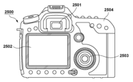
図25は、本実施形態の発光装置101を用いた光電変換装置の一例を表す模式図である。光電変換装置2500は、ビューファインダ2501、背面ディスプレイ2502、操作部2503、筐体2504を有してよい。光電変換装置2500は、撮像装置とも呼ばれうる。表示部であるビューファインダ2501に、有機層502の発光層が有機発光材料を含む上述の発光装置101が適用できる。この場合、発光装置101は、撮像する画像のみならず、環境情報、撮像指示などを表示してもよい。環境情報には、外光の強度、外光の向き、被写体の動く速度、被写体が遮蔽物に遮蔽される可能性などであってよい。
FIG. 25 is a schematic diagram showing an example of a photoelectric conversion device using the
撮像に適するタイミングはわずかな時間である場合が多いため、少しでも早く情報を表示した方がよい。したがって、上述の有機層502の発光層が有機発光材料を含む発光装置101がビューファインダ2501に用いられうる。有機発光材料は応答速度が速いためである。有機発光材料を用いた発光装置101は、表示速度が求められる、これらの装置に、液晶表示装置よりも適して用いることができる。
Since the timing suitable for imaging is often short, it is better to display the information as soon as possible. Therefore, the light-emitting
光電変換装置2500は、不図示の光学部を有する。光学部は複数のレンズを有し、光学部を通過した光を受光する筐体2504内に収容されている光電変換素子(不図示)に結像する。複数のレンズは、その相対位置を調整することで、焦点を調整することができる。この操作を自動で行うこともできる。
The
有機層502の発光層が有機発光材料を含む上述の発光装置101は、電子機器の表示部に適用されてもよい。その際には、表示機能と操作機能との双方を有してもよい。携帯端末としては、スマートフォンなどの携帯電話、タブレット、ヘッドマウントディスプレイなどが挙げられる。
The light-emitting
図26は、本実施形態の発光装置101を用いた電子機器の一例を表す模式図である。電子機器2600は、表示部2601と、操作部2602と、筐体2603と、を有する。筐体2603には、回路、当該回路を有するプリント基板、バッテリー、通信部、を有してよい。操作部2602は、ボタンであってもよいし、タッチパネル方式の反応部であってもよい。操作部2602は、指紋を認識してロックの解除等を行う、生体認識部であってもよい。通信部を有する携帯機器は通信機器ということもできる。表示部2601には、有機層502の発光層が有機発光材料を含む上述の発光装置101が適用できる。
FIG. 26 is a schematic diagram showing an example of an electronic device using the
図27(a)、27(b)は、本実施形態の発光装置101を用いた表示装置の一例を表す模式図である。図27(a)は、テレビモニタやPCモニタなどの表示装置である。表示装置2700は、額縁2701を有し表示部2702を有する。表示部2702に、有機層502の発光層が有機発光材料を含む上述の発光装置101が適用できる。表示装置2700は、額縁2701と表示部2702とを支える土台2703を有していてもよい。土台2703は、図27(a)の形態に限られない。例えば、額縁2701の下辺が土台2703を兼ねていてもよい。また、額縁2701および表示部2702は、曲がっていてもよい。その曲率半径は、5000mm以上6000mm以下であってよい。
27(a) and 27(b) are schematic diagrams showing an example of a display device using the
図27(b)は、本実施形態の発光装置101を用いた表示装置の他の例を表す模式図である。図27(b)の表示装置2710は、折り曲げ可能に構成されており、いわゆるフォルダブルな表示装置である。表示装置2710は、第1表示部2711、第2表示部2712、筐体2713、屈曲点2714を有する。第1表示部2711と第2表示部2712とには、有機層502の発光層が有機発光材料を含む上述の発光装置101が適用できる。第1表示部2711と第2表示部2712とは、つなぎ目のない1枚の表示装置であってよい。第1表示部2711と第2表示部2712とは、屈曲点で分けることができる。第1表示部2711と第2表示部2712とは、それぞれ異なる画像を表示してもよいし、第1表示部2711と第2表示部2712とで1つの画像を表示してもよい。
FIG. 27B is a schematic diagram showing another example of a display device using the
図28は、本実施形態の発光装置101を用いた照明装置の一例を表す模式図である。照明装置2800は、筐体2801と、光源2802と、回路基板2803と、光学フィルム2804と、光拡散部2805と、を有していてもよい。光源2802には、有機層502の発光層が有機発光材料を含む上述の発光装置101が適用できる。光学フィルム2804は光源の演色性を向上させるフィルタであってよい。光拡散部2805は、ライトアップなど、光源の光を効果的に拡散し、広い範囲に光を届けることができる。必要に応じて、最外部にカバーを設けてもよい。照明装置2800は、光学フィルム2804と光拡散部2805との両方を有していてもよいし、何れか一方のみを有していてもよい。
FIG. 28 is a schematic diagram showing an example of a lighting device using the
照明装置2800は例えば室内を照明する装置である。照明装置2800は白色、昼白色、その他青から赤のいずれの色を発光するものであってよい。それらを調光する調光回路を有してよい。照明装置2800は、光源2802として機能する発光装置101に接続される電源回路を有していてもよい。電源回路は、交流電圧を直流電圧に変換する回路である。また、白とは色温度が4200Kで昼白色とは色温度が5000Kである。また、照明装置2800は、カラーフィルタを有してもよい。また、照明装置2800は、放熱部を有していてもよい。放熱部は装置内の熱を装置外へ放出するものであり、比熱の高い金属、液体シリコンなどが挙げられる。
A
図29は、本実施形態の発光装置101を用いた車両用の灯具の一例であるテールランプを有する自動車の模式図である。自動車2900は、テールランプ2901を有し、ブレーキ操作などを行った際に、テールランプ2901を点灯する形態であってもよい。本実施形態の発光装置101は、車両用の灯具としてヘッドランプに用いられてもよい。自動車は移動体の一例であり、移動体は船舶やドローン、航空機、鉄道車両などであってもよい。移動体は、機体とそれに設けられた灯具を有してよい。灯具は機体の現在位置を知らせるものであってもよい。
FIG. 29 is a schematic diagram of a vehicle having a tail lamp, which is an example of a vehicle lamp using the
テールランプ2901に、有機層502の発光層が有機発光材料を含む上述の発光装置101が適用できる。テールランプ2901は、テールランプ2901として機能する発光装置101を保護する保護部材を有してよい。保護部材は、ある程度高い強度を有し、透明であれば材料は問わないが、ポリカーボネートなどで構成されてもよい。また、保護部材は、ポリカーボネートにフランジカルボン酸誘導体、アクリロニトリル誘導体などを混ぜてよい。
The light-emitting
自動車2900は、車体2903、それに取り付けられている窓2902を有してもよい。窓は、自動車の前後を確認するための窓であってもよいし、透明なディスプレイであってもよい。当該透明なディスプレイは、有機層502の発光層が有機発光材料を含む上述の発光装置101が用いられてもよい。この場合、発光装置101が有する電極などの構成材料は透明な部材で構成される。
発明は上記実施形態に制限されるものではなく、発明の精神及び範囲から離脱することなく、様々な変更及び変形が可能である。従って、発明の範囲を公にするために請求項を添付する。 The invention is not limited to the embodiments described above, and various modifications and variations are possible without departing from the spirit and scope of the invention. Accordingly, the claims are appended to make public the scope of the invention.
101:発光装置、102:画素、201:発光素子、510:基板 101: light emitting device, 102: pixel, 201: light emitting element, 510: substrate
Claims (23)
前記複数の画素のそれぞれは、発光素子と、前記発光素子の陽極にドレイン領域が接続された第1トランジスタと、前記第1トランジスタのゲート電極にドレイン領域が接続された第2トランジスタと、を備え、
前記複数の画素は、前記第1方向に互いに隣接する第1画素と第2画素とを含み、
前記第1画素の前記第2トランジスタのソース領域と、前記第2画素の前記第2トランジスタのソース領域と、は1つの拡散領域を共有し、
前記第1画素の前記第1トランジスタのソース領域、ゲート電極、ドレイン領域および前記第2画素の前記第1トランジスタのソース領域、ゲート電極、ドレイン領域は、前記第1方向の正または負のうち一方の方向に、それぞれ順に配されることを特徴とする発光装置。 A light-emitting device in which a plurality of pixels are arranged on a substrate in an array in a first direction and in a second direction intersecting the first direction,
Each of the plurality of pixels includes a light emitting element, a first transistor having a drain region connected to an anode of the light emitting element, and a second transistor having a drain region connected to a gate electrode of the first transistor. ,
the plurality of pixels includes a first pixel and a second pixel adjacent to each other in the first direction;
a source region of the second transistor of the first pixel and a source region of the second transistor of the second pixel share a diffusion region;
The source region, gate electrode and drain region of the first transistor of the first pixel and the source region, gate electrode and drain region of the first transistor of the second pixel are either positive or negative in the first direction. A light-emitting device characterized in that they are arranged in order in the directions of .
前記第1画素および前記第2画素のうち一方の画素の前記第1トランジスタのゲート電極と前記第2トランジスタのドレイン領域との間の長さが、前記第1画素および前記第2画素のうち他方の画素の前記第1トランジスタのゲート電極と前記第2トランジスタのドレイン領域との間の長さよりも長いことを特徴とする請求項1に記載の発光装置。 each of the plurality of pixels further comprises a wiring pattern for connecting the gate electrode of the first transistor and the drain region of the second transistor;
The length between the gate electrode of the first transistor and the drain region of the second transistor of one of the first pixel and the second pixel is equal to the length of the other of the first pixel and the second pixel. 2. The light emitting device according to claim 1, wherein the length is longer than the length between the gate electrode of the first transistor and the drain region of the second transistor of each pixel.
前記一方の画素の前記配線パターンのうち前記第1方向に沿って延在する部分は、前記第2方向に沿って延在する部分よりも前記第2画素の側に配された第1部分を含み、
前記他方の画素の前記配線パターンのうち前記第1方向に沿って延在する部分は、前記第2方向に沿って延在する部分よりも前記第1画素の側に配された第2部分を含み、
前記第1部分の長さが、前記第2部分の長さよりも短いことを特徴とする請求項2乃至5の何れか1項に記載の発光装置。 the wiring pattern includes a portion extending along the first direction and a portion extending along the second direction;
The portion of the wiring pattern of the one pixel that extends along the first direction is arranged closer to the second pixel than the portion that extends along the second direction. including
A portion of the wiring pattern of the other pixel that extends along the first direction includes a second portion arranged closer to the first pixel than a portion that extends along the second direction. including
6. The light emitting device according to any one of claims 2 to 5, wherein the length of the first portion is shorter than the length of the second portion.
前記第1方向において、
前記第1画素の前記第1トランジスタと前記第2トランジスタとの間に、前記第1画素の前記第3トランジスタが配され、
前記第2画素の前記第1トランジスタの前記第1画素とは反対の側に、前記第2画素の前記第3トランジスタが配されることを特徴とする請求項7に記載の発光装置。 each of the plurality of pixels further comprises a third transistor for controlling light emission or non-light emission of the light emitting element, the drain region of which is connected to the source region of the first transistor;
in the first direction,
the third transistor of the first pixel is arranged between the first transistor and the second transistor of the first pixel;
8. The light emitting device according to claim 7, wherein the third transistor of the second pixel is arranged on the opposite side of the first transistor of the second pixel from the first pixel.
前記第1方向において、前記第1画素の前記第1トランジスタと前記第2画素の前記第1トランジスタとの間に、前記第1画素の前記第3トランジスタおよび前記第2画素の前記第3トランジスタが配され、
前記第1画素の前記第3トランジスタのソース領域と、前記第2画素の前記第3トランジスタのソース領域と、は1つの拡散領域を共有し、
前記第1画素の前記第2トランジスタおよび前記第2画素の前記第2トランジスタと、前記第1画素の前記第3トランジスタおよび前記第2画素の前記第3トランジスタと、が前記第2方向に並んで配されることを特徴とする請求項7に記載の発光装置。 each of the plurality of pixels further comprises a third transistor for controlling light emission or non-light emission of the light emitting element, the drain region of which is connected to the source region of the first transistor;
The third transistor of the first pixel and the third transistor of the second pixel are arranged between the first transistor of the first pixel and the first transistor of the second pixel in the first direction. distributed,
a source region of the third transistor of the first pixel and a source region of the third transistor of the second pixel share one diffusion region;
The second transistor of the first pixel and the second transistor of the second pixel, and the third transistor of the first pixel and the third transistor of the second pixel are arranged in the second direction. 8. The light-emitting device of claim 7, wherein a
前記第1方向において、
前記第1画素の前記第1トランジスタと前記第2画素の前記第1トランジスタとの間に、前記第1画素の第3トランジスタ、および、前記第2画素の第4トランジスタが配され、
前記第1画素の前記第1トランジスタの前記第2画素とは反対の側に、前記第1画素の前記第4トランジスタが配され、
前記第2画素の前記第1トランジスタの前記第1画素とは反対の側に、前記第2画素の前記第3トランジスタが配され、
前記第2方向に、前記第1画素の前記第2トランジスタおよび前記第2画素の前記第2トランジスタと、前記第1画素の第3トランジスタおよび前記第2画素の第4トランジスタと、が並んで配されることを特徴とする請求項7に記載の発光装置。 Each of the plurality of pixels includes a third transistor having a drain region connected to the source region of the first transistor for controlling light emission or non-light emission of the light emitting element, and a third transistor for resetting the light emitting element. 4 transistors, and
in the first direction,
a third transistor of the first pixel and a fourth transistor of the second pixel are arranged between the first transistor of the first pixel and the first transistor of the second pixel;
the fourth transistor of the first pixel is arranged on the side opposite to the second pixel of the first transistor of the first pixel;
the third transistor of the second pixel is arranged on the side opposite to the first pixel of the first transistor of the second pixel;
The second transistor of the first pixel and the second transistor of the second pixel, and the third transistor of the first pixel and the fourth transistor of the second pixel are arranged side by side in the second direction. 8. The light-emitting device of claim 7, wherein:
前記第1方向において、
前記第1画素の前記第1トランジスタと前記第2画素の前記第1トランジスタとの間に、前記第1画素の前記第4トランジスタおよび前記第2画素の前記第4トランジスタが配され、
前記第1画素の前記第1トランジスタと前記第1画素の前記第2トランジスタとの間に、前記第1画素の前記第3トランジスタが配され、
前記第2画素の前記第1トランジスタの前記第1画素とは反対の側に、前記第2画素の前記第3トランジスタが配され、
前記第2方向に、前記第1画素の前記第2トランジスタおよび前記第2画素の前記第2トランジスタと、前記第1画素の前記第4トランジスタおよび前記第2画素の前記第4トランジスタと、が並んで配されることを特徴とする請求項7に記載の発光装置。 Each of the plurality of pixels includes a third transistor having a drain region connected to the source region of the first transistor for controlling light emission or non-light emission of the light emitting element, and a third transistor for resetting the light emitting element. 4 transistors, and
in the first direction,
the fourth transistor of the first pixel and the fourth transistor of the second pixel are arranged between the first transistor of the first pixel and the first transistor of the second pixel;
the third transistor of the first pixel is arranged between the first transistor of the first pixel and the second transistor of the first pixel;
the third transistor of the second pixel is arranged on the side opposite to the first pixel of the first transistor of the second pixel;
The second transistor of the first pixel and the second transistor of the second pixel, and the fourth transistor of the first pixel and the fourth transistor of the second pixel are arranged in the second direction. 8. The light-emitting device according to claim 7, wherein the light-emitting device is arranged at .
前記第1方向において、
前記第3画素の前記第1トランジスタと前記第4画素の前記第1トランジスタとの間に、前記第3画素の前記第2トランジスタおよび前記第4画素の前記第2トランジスタと前記第3画素の前記第4トランジスタおよび前記第4画素の前記第4トランジスタと、が配され、
前記第3画素の前記第1トランジスタと前記第3画素の前記第2トランジスタとの間に、前記第3画素の前記第3トランジスタが配され、
前記第4画素の前記第1トランジスタの前記第3画素とは反対の側に、前記第4画素の前記第3トランジスタが配され、
前記第2方向に、前記第1画素の前記第2トランジスタおよび前記第2画素の前記第2トランジスタと前記第3画素および前記第4画素の前記第2トランジスタとの間に、前記第1画素の前記第4トランジスタ、前記第2画素の前記第4トランジスタ、前記第3画素の前記第4トランジスタおよび前記第4画素の前記第4トランジスタが配され、
前記第1画素の前記第4トランジスタのドレイン領域と、前記第2画素の前記第4トランジスタのドレイン領域と、前記第3画素の前記第4トランジスタのドレイン領域と、前記第4画素の前記第4トランジスタのドレイン領域と、が1つの拡散領域を共有していることを特徴とする請求項13に記載の発光装置。 The plurality of pixels includes: a third pixel arranged adjacent to the first pixel in the second direction; and the second pixel adjacent to the third pixel in the first direction. and a fourth pixel arranged adjacent to the second direction,
in the first direction,
Between the first transistor of the third pixel and the first transistor of the fourth pixel, the second transistor of the third pixel and the second transistor of the fourth pixel and the third pixel are provided. a fourth transistor and the fourth transistor of the fourth pixel;
the third transistor of the third pixel is arranged between the first transistor of the third pixel and the second transistor of the third pixel;
the third transistor of the fourth pixel is arranged on the opposite side of the first transistor of the fourth pixel from the third pixel;
between the second transistor of the first pixel and the second transistor of the second pixel and the second transistor of the third pixel and the fourth pixel in the second direction; the fourth transistor, the fourth transistor of the second pixel, the fourth transistor of the third pixel, and the fourth transistor of the fourth pixel are arranged;
a drain region of the fourth transistor of the first pixel; a drain region of the fourth transistor of the second pixel; a drain region of the fourth transistor of the third pixel; 14. The light emitting device of claim 13, wherein the drain region of the transistor shares a diffusion region.
前記表示部は、前記撮像素子が撮像した画像を表示する表示部であり、かつ、請求項1乃至18の何れか1項に記載の発光装置を有することを特徴とする光電変換装置。 An optical unit having a plurality of lenses, an imaging device that receives light that has passed through the optical unit, and a display unit that displays an image,
19. A photoelectric conversion device, wherein the display unit displays an image picked up by the imaging element, and comprises the light emitting device according to claim 1.
前記表示部は、請求項1乃至18の何れか1項に記載の発光装置を有することを特徴とする電子機器。 A housing provided with a display unit, and a communication unit provided in the housing and communicating with the outside,
19. An electronic device, wherein the display unit comprises the light emitting device according to claim 1.
前記光源は、請求項1乃至18の何れか1項に記載の発光装置を有することを特徴とする照明装置。 A lighting device having a light source and at least one of a light diffusion portion and an optical film,
19. An illumination device, wherein the light source comprises the light emitting device according to any one of claims 1 to 18.
前記灯具は、請求項1乃至18の何れか1項に記載の発光装置を有することを特徴とする移動体。 having a fuselage and a lamp provided on the fuselage,
19. A moving body, wherein the lamp includes the light emitting device according to claim 1.
Priority Applications (4)
| Application Number | Priority Date | Filing Date | Title |
|---|---|---|---|
| JP2019188006A JP7321049B2 (en) | 2019-10-11 | 2019-10-11 | Light-emitting devices, display devices, photoelectric conversion devices, electronic devices, lighting devices, and moving bodies |
| US17/036,169 US11527591B2 (en) | 2019-10-11 | 2020-09-29 | Light emitting device for display device miniaturizing pixels and suppressing degradation in image quality |
| US17/985,210 US11943970B2 (en) | 2019-10-11 | 2022-11-11 | Light emitting device, display device, photoelectric conversion device, electronic device, illumination device, and mobile device with first transistor connected to light emitting element anode, second transistor connected to first transistor gate electrode, and third transistor connected to first transistor |
| JP2023119296A JP2023133411A (en) | 2019-10-11 | 2023-07-21 | Light emitting device, display device, photoelectric conversion device, electronic device, illumination device, and movable body |
Applications Claiming Priority (1)
| Application Number | Priority Date | Filing Date | Title |
|---|---|---|---|
| JP2019188006A JP7321049B2 (en) | 2019-10-11 | 2019-10-11 | Light-emitting devices, display devices, photoelectric conversion devices, electronic devices, lighting devices, and moving bodies |
Related Child Applications (1)
| Application Number | Title | Priority Date | Filing Date |
|---|---|---|---|
| JP2023119296A Division JP2023133411A (en) | 2019-10-11 | 2023-07-21 | Light emitting device, display device, photoelectric conversion device, electronic device, illumination device, and movable body |
Publications (2)
| Publication Number | Publication Date |
|---|---|
| JP2021063902A JP2021063902A (en) | 2021-04-22 |
| JP7321049B2 true JP7321049B2 (en) | 2023-08-04 |
Family
ID=75383375
Family Applications (2)
| Application Number | Title | Priority Date | Filing Date |
|---|---|---|---|
| JP2019188006A Active JP7321049B2 (en) | 2019-10-11 | 2019-10-11 | Light-emitting devices, display devices, photoelectric conversion devices, electronic devices, lighting devices, and moving bodies |
| JP2023119296A Pending JP2023133411A (en) | 2019-10-11 | 2023-07-21 | Light emitting device, display device, photoelectric conversion device, electronic device, illumination device, and movable body |
Family Applications After (1)
| Application Number | Title | Priority Date | Filing Date |
|---|---|---|---|
| JP2023119296A Pending JP2023133411A (en) | 2019-10-11 | 2023-07-21 | Light emitting device, display device, photoelectric conversion device, electronic device, illumination device, and movable body |
Country Status (2)
| Country | Link |
|---|---|
| US (2) | US11527591B2 (en) |
| JP (2) | JP7321049B2 (en) |
Families Citing this family (7)
| Publication number | Priority date | Publication date | Assignee | Title |
|---|---|---|---|---|
| CN112309332B (en) * | 2019-07-31 | 2022-01-18 | 京东方科技集团股份有限公司 | Pixel circuit, driving method thereof, display substrate and display panel |
| JP7321049B2 (en) * | 2019-10-11 | 2023-08-04 | キヤノン株式会社 | Light-emitting devices, display devices, photoelectric conversion devices, electronic devices, lighting devices, and moving bodies |
| CN111179851A (en) * | 2020-02-25 | 2020-05-19 | 合肥鑫晟光电科技有限公司 | Pixel circuit, driving method thereof and display device |
| JP2021189278A (en) | 2020-05-28 | 2021-12-13 | キヤノン株式会社 | Light-emitting device and electronic apparatus |
| JP7479203B2 (en) | 2020-06-04 | 2024-05-08 | キヤノン株式会社 | Light-emitting device, display device, photoelectric conversion device, electronic device, lighting device, mobile object, and wearable device |
| JP2022108623A (en) | 2021-01-13 | 2022-07-26 | キヤノン株式会社 | Light emitting device, display, photoelectric conversion device, electronic apparatus, lighting device, movable body, and wearable device |
| JP2022112370A (en) | 2021-01-21 | 2022-08-02 | キヤノン株式会社 | Light emitting device, photoelectric conversion device, electronic apparatus, illumination device, and movable body |
Citations (6)
| Publication number | Priority date | Publication date | Assignee | Title |
|---|---|---|---|---|
| JP2013213979A (en) | 2012-04-03 | 2013-10-17 | Seiko Epson Corp | Electro-optic device and electronic equipment |
| JP2014098779A (en) | 2012-11-14 | 2014-05-29 | Sony Corp | Light-emitting element, display device and electronic apparatus |
| JP2014102319A (en) | 2012-11-19 | 2014-06-05 | Sony Corp | Light-emitting element and display device |
| JP2016213436A (en) | 2015-05-01 | 2016-12-15 | セイコーエプソン株式会社 | Electro-optic device, electronic apparatus, and method for manufacturing electro-optic device |
| WO2018047504A1 (en) | 2016-09-09 | 2018-03-15 | ソニーセミコンダクタソリューションズ株式会社 | Display device and electronic device |
| US20190180696A1 (en) | 2017-12-12 | 2019-06-13 | Lg Display Co., Ltd. | Micro Display Device and Display Integrated Circuit |
Family Cites Families (29)
| Publication number | Priority date | Publication date | Assignee | Title |
|---|---|---|---|---|
| JP2005292272A (en) * | 2004-03-31 | 2005-10-20 | Tohoku Pioneer Corp | Drive unit of light emitting display panel and driving method |
| KR100637164B1 (en) * | 2004-06-26 | 2006-10-20 | 삼성에스디아이 주식회사 | Active matrix type electroluminescence display device |
| US7583429B2 (en) * | 2004-09-27 | 2009-09-01 | Idc, Llc | Ornamental display device |
| JP4289332B2 (en) * | 2004-09-30 | 2009-07-01 | セイコーエプソン株式会社 | EL display device, method for manufacturing EL display device, and electronic apparatus |
| US20100187609A1 (en) * | 2009-01-27 | 2010-07-29 | Synopsys, Inc. | Boosting transistor performance with non-rectangular channels |
| JP2011221070A (en) * | 2010-04-05 | 2011-11-04 | Seiko Epson Corp | Light-emitting device and electronic apparatus, and method for driving light-emitting device |
| JP5970758B2 (en) * | 2011-08-10 | 2016-08-17 | セイコーエプソン株式会社 | Electro-optical device, driving method of electro-optical device, and electronic apparatus |
| US9786223B2 (en) * | 2012-12-11 | 2017-10-10 | Ignis Innovation Inc. | Pixel circuits for AMOLED displays |
| JP6131662B2 (en) * | 2013-03-22 | 2017-05-24 | セイコーエプソン株式会社 | Display device and electronic device |
| JP5849981B2 (en) | 2013-03-25 | 2016-02-03 | ソニー株式会社 | Display device and electronic device |
| JP6263862B2 (en) * | 2013-04-26 | 2018-01-24 | 株式会社Jvcケンウッド | Liquid crystal display |
| JP5735162B1 (en) * | 2014-07-18 | 2015-06-17 | Lumiotec株式会社 | Organic electroluminescent device and lighting device |
| KR102241704B1 (en) * | 2014-08-07 | 2021-04-20 | 삼성디스플레이 주식회사 | Pixel circuit and organic light emitting display device having the same |
| US10211205B2 (en) * | 2016-04-27 | 2019-02-19 | International Business Machines Corporation | Field effect transistor structure for reducing contact resistance |
| JP6813971B2 (en) * | 2016-07-07 | 2021-01-13 | キヤノン株式会社 | Photoelectric conversion device and imaging system |
| KR102391454B1 (en) * | 2017-10-18 | 2022-04-27 | 엘지디스플레이 주식회사 | Organic light emitting display device and driving method |
| JP7043284B2 (en) * | 2018-02-15 | 2022-03-29 | キヤノン株式会社 | Imaging equipment and systems, and moving objects |
| JP7141241B2 (en) | 2018-05-17 | 2022-09-22 | キヤノン株式会社 | Display device |
| JP7145032B2 (en) | 2018-10-19 | 2022-09-30 | キヤノン株式会社 | Displays and electronics |
| JP7117974B2 (en) * | 2018-10-30 | 2022-08-15 | キヤノン株式会社 | Displays and electronics |
| JP7204429B2 (en) | 2018-11-06 | 2023-01-16 | キヤノン株式会社 | Displays and electronics |
| US11087680B2 (en) | 2018-11-07 | 2021-08-10 | Canon Kabushiki Kaisha | Display device, image capturing device, illumination device, mobile body, and electronic apparatus |
| JP7321049B2 (en) * | 2019-10-11 | 2023-08-04 | キヤノン株式会社 | Light-emitting devices, display devices, photoelectric conversion devices, electronic devices, lighting devices, and moving bodies |
| JP7397694B2 (en) * | 2020-01-30 | 2023-12-13 | キヤノン株式会社 | Light emitting devices, imaging devices, electronic equipment and moving objects |
| JP7479203B2 (en) * | 2020-06-04 | 2024-05-08 | キヤノン株式会社 | Light-emitting device, display device, photoelectric conversion device, electronic device, lighting device, mobile object, and wearable device |
| JP2022085258A (en) * | 2020-11-27 | 2022-06-08 | キヤノン株式会社 | Light-emitting device, display device, photoelectric conversion device, electronic appliance, illumination device, and mobile body |
| JP2022085287A (en) * | 2020-11-27 | 2022-06-08 | キヤノン株式会社 | Light-emitting device |
| JP2023032244A (en) * | 2021-08-26 | 2023-03-09 | キヤノン株式会社 | Display apparatus, photoelectric conversion apparatus, electronic apparatus, illumination apparatus, moving body, and wearable device |
| JP2023160137A (en) * | 2022-04-21 | 2023-11-02 | キヤノン株式会社 | Light-emitting device, display device, photoelectric conversion device, electronic apparatus, luminaire, and movable body |
-
2019
- 2019-10-11 JP JP2019188006A patent/JP7321049B2/en active Active
-
2020
- 2020-09-29 US US17/036,169 patent/US11527591B2/en active Active
-
2022
- 2022-11-11 US US17/985,210 patent/US11943970B2/en active Active
-
2023
- 2023-07-21 JP JP2023119296A patent/JP2023133411A/en active Pending
Patent Citations (6)
| Publication number | Priority date | Publication date | Assignee | Title |
|---|---|---|---|---|
| JP2013213979A (en) | 2012-04-03 | 2013-10-17 | Seiko Epson Corp | Electro-optic device and electronic equipment |
| JP2014098779A (en) | 2012-11-14 | 2014-05-29 | Sony Corp | Light-emitting element, display device and electronic apparatus |
| JP2014102319A (en) | 2012-11-19 | 2014-06-05 | Sony Corp | Light-emitting element and display device |
| JP2016213436A (en) | 2015-05-01 | 2016-12-15 | セイコーエプソン株式会社 | Electro-optic device, electronic apparatus, and method for manufacturing electro-optic device |
| WO2018047504A1 (en) | 2016-09-09 | 2018-03-15 | ソニーセミコンダクタソリューションズ株式会社 | Display device and electronic device |
| US20190180696A1 (en) | 2017-12-12 | 2019-06-13 | Lg Display Co., Ltd. | Micro Display Device and Display Integrated Circuit |
Also Published As
| Publication number | Publication date |
|---|---|
| US20230071385A1 (en) | 2023-03-09 |
| US20210111227A1 (en) | 2021-04-15 |
| JP2023133411A (en) | 2023-09-22 |
| JP2021063902A (en) | 2021-04-22 |
| US11527591B2 (en) | 2022-12-13 |
| US11943970B2 (en) | 2024-03-26 |
Similar Documents
| Publication | Publication Date | Title |
|---|---|---|
| JP7321049B2 (en) | Light-emitting devices, display devices, photoelectric conversion devices, electronic devices, lighting devices, and moving bodies | |
| US11087680B2 (en) | Display device, image capturing device, illumination device, mobile body, and electronic apparatus | |
| TWI636447B (en) | Organic light-emitting display device | |
| CN108028264B (en) | Electroluminescent display device | |
| US10177210B2 (en) | Display device having redundant wirings | |
| JP6818837B2 (en) | Display devices, imaging devices, lighting devices, mobiles and electronic devices | |
| JP7397694B2 (en) | Light emitting devices, imaging devices, electronic equipment and moving objects | |
| US11417722B2 (en) | Display device including a low resistance cathode wiring | |
| US11521552B2 (en) | Display device | |
| CN114072724B (en) | Display substrate and display device | |
| CN113793856B (en) | Display substrate, preparation method thereof and display device | |
| CN114843310A (en) | Display device and method for manufacturing the same | |
| CN115136316A (en) | Reducing aperture bezel area in a display | |
| WO2023233760A1 (en) | Light-emitting device, display device, photoelectric conversion device, electronic equipment, and method for manufacturing light-emitting device | |
| US11903264B2 (en) | Display device | |
| CN112750403A (en) | Display apparatus, photoelectric conversion apparatus, electronic apparatus, illumination apparatus, and moving object | |
| JP2024074234A (en) | Light-emitting device, display device, photoelectric conversion device, electronic device, lighting device, and mobile object | |
| JP2023177215A (en) | Light-emitting device, display unit, photoelectric conversion device, electronic equipment, and method of manufacturing light-emitting device | |
| KR20240040176A (en) | Display device and method for manufacturing the same | |
| CN113497102A (en) | Display device | |
| KR20240077528A (en) | Display Apparatus | |
| KR20240013996A (en) | Display apparatus | |
| JP2023074474A (en) | Display device and display panel | |
| CN116018010A (en) | Display substrate and display device | |
| CN115707302A (en) | Display device and electronic apparatus including the same |
Legal Events
| Date | Code | Title | Description |
|---|---|---|---|
| RD01 | Notification of change of attorney |
Free format text: JAPANESE INTERMEDIATE CODE: A7421 Effective date: 20210103 |
|
| A521 | Request for written amendment filed |
Free format text: JAPANESE INTERMEDIATE CODE: A523 Effective date: 20210113 |
|
| A621 | Written request for application examination |
Free format text: JAPANESE INTERMEDIATE CODE: A621 Effective date: 20220930 |
|
| A977 | Report on retrieval |
Free format text: JAPANESE INTERMEDIATE CODE: A971007 Effective date: 20230614 |
|
| TRDD | Decision of grant or rejection written | ||
| A01 | Written decision to grant a patent or to grant a registration (utility model) |
Free format text: JAPANESE INTERMEDIATE CODE: A01 Effective date: 20230626 |
|
| A61 | First payment of annual fees (during grant procedure) |
Free format text: JAPANESE INTERMEDIATE CODE: A61 Effective date: 20230725 |
|
| R151 | Written notification of patent or utility model registration |
Ref document number: 7321049 Country of ref document: JP Free format text: JAPANESE INTERMEDIATE CODE: R151 |