JP7310316B2 - volume hologram, retinal scanning display, head-mounted display - Google Patents
volume hologram, retinal scanning display, head-mounted display Download PDFInfo
- Publication number
- JP7310316B2 JP7310316B2 JP2019102340A JP2019102340A JP7310316B2 JP 7310316 B2 JP7310316 B2 JP 7310316B2 JP 2019102340 A JP2019102340 A JP 2019102340A JP 2019102340 A JP2019102340 A JP 2019102340A JP 7310316 B2 JP7310316 B2 JP 7310316B2
- Authority
- JP
- Japan
- Prior art keywords
- volume hologram
- relationship
- laser light
- diffraction efficiency
- display device
- Prior art date
- Legal status (The legal status is an assumption and is not a legal conclusion. Google has not performed a legal analysis and makes no representation as to the accuracy of the status listed.)
- Active
Links
Images


Landscapes
- Diffracting Gratings Or Hologram Optical Elements (AREA)
- Holo Graphy (AREA)
Description
本発明は、体積ホログラム、網膜走査型表示装置、頭部装着型表示装置に関するものである。 The present invention relates to volume holograms, retinal scanning display devices, and head-mounted display devices.
レーザー光源からのレーザー光を走査して網膜へ直接描画を行う網膜走査型表示装置が知られている(例えば、特許文献1)。特許文献1では、レーザー光の向きを眼に向かう方向へ偏向させる偏向部として体積ホログラムを用いる例が示されている。体積ホログラムを用いることにより、凹面鏡を用いる場合に比べて、装置を小型化することが可能である。また、レーザー光は、波長帯域が極めて狭く略単波長の光であり、また、体積ホログラムについても波長選択性を備えることから、体積ホログラムによってレーザー光の波長についてのみ回折反射を行い、他の波長の光を透過させることが容易である。
2. Description of the Related Art A retinal scanning display device that scans a laser beam from a laser light source and draws images directly on the retina is known (for example, Patent Document 1).
しかし、体積ホログラムが温度変化によって膨張、又は、収縮すると、体積ホログラムが回折反射する光のピーク波長が変化してしまい、所望の回折効率が得られず、暗い映像しか観察できなかったり、観察される画像の色バランスがずれてしまったりするおそれがあった。 However, when the volume hologram expands or shrinks due to temperature changes, the peak wavelength of the light diffracted and reflected by the volume hologram changes, making it impossible to obtain the desired diffraction efficiency. There is a risk that the color balance of the image may be out of alignment.
本発明の課題は、温度変化による回折効率の変化を抑えることができる体積ホログラム、網膜走査型表示装置を提供することである。 SUMMARY OF THE INVENTION An object of the present invention is to provide a volume hologram and a retinal scanning display device capable of suppressing changes in diffraction efficiency caused by temperature changes.
本発明は、以下のような解決手段により、前記課題を解決する。なお、理解を容易にするために、本発明の実施形態に対応する符号を付して説明するが、これに限定されるものではない。 The present invention solves the above problems by means of the following solutions. In order to facilitate understanding, reference numerals corresponding to the embodiments of the present invention will be used for explanation, but the present invention is not limited thereto.
第1の発明は、レーザー光源(10)を用いた光学エンジンの映像光を偏向させる偏向部(30)として用いられる体積ホログラム(30)であって、分光分布曲線において半値幅が5nm以上である体積ホログラム(30)である。 A first invention is a volume hologram (30) used as a deflector (30) for deflecting image light of an optical engine using a laser light source (10), wherein the spectral distribution curve has a half width of 5 nm or more. Volume hologram (30).
第2の発明は、レーザー光源(10)からのレーザー光を走査して網膜へ直接描画を行う網膜走査型表示装置に用いられ、走査されたレーザー光の向きを偏向させる偏向部(30)として用いられる体積ホログラム(30)であって、分光分布曲線において半値幅が5nm以上である体積ホログラム(30)である。 The second invention is used in a retinal scanning display device that scans laser light from a laser light source (10) and directly draws images on the retina, and as a deflector (30) that deflects the direction of the scanned laser light. A volume hologram (30) to be used, the volume hologram (30) having a half width of 5 nm or more in a spectral distribution curve.
第3の発明は、第1の発明又は第2の発明に記載の体積ホログラム(30)において、当該体積ホログラム(30)の膜厚をt(μm)、屈折率変調量をΔnとしたときに、Δn≧-5×10⁻⁶t2+0.003t+0.0007、ただし、t≧30μmの場合には、Δn≧0.005の関係を満たすこと、を特徴とする体積ホログラム(30)である。 A third invention is the volume hologram (30) according to the first invention or the second invention, wherein when the film thickness of the volume hologram (30) is t (μm) and the refractive index modulation amount is Δn, , Δn≧−5×10 −6 t 2 +0.003t+0.0007, provided that when t≧30 μm, the relationship Δn≧0.005 is satisfied.
第4の発明は、第1の発明から第3の発明までのいずれかに記載の体積ホログラム(30)において、当該体積ホログラム(30)の膜厚をt(μm)、屈折率変調量をΔnとしたときに、Δn≦0.0641t(-1.049)の関係を満たすこと、を特徴とする体積ホログラム(30)である。 A fourth invention is the volume hologram (30) according to any one of the first invention to the third invention, wherein the film thickness of the volume hologram (30) is t (μm) and the refractive index modulation amount is Δn A volume hologram (30) characterized by satisfying the relationship Δn≦0.0641t (−1.049) when .
第5の発明は、第1の発明から第4の発明までのいずれかに記載の体積ホログラム(30)において、当該体積ホログラム(30)へ入射角θ1で入射したレーザー光の出射角をθ2としたときに、0°≦θ1≦85°、かつ、100°≦θ2≦260°の範囲内において、θ2≦0.3214θ1+234.75、かつ、θ2≧-θ1+118.33の双方の関係を満たすこと、を特徴とする体積ホログラム(30)である。
A fifth invention is the volume hologram (30) according to any one of the first invention to the fourth invention, wherein the emission angle of the laser beam incident on the volume hologram (30) at the incident angle θ 1 is θ 2 ,
第6の発明は、第5の発明に記載の体積ホログラム(30)において、θ2≧160°の場合は、θ2≦82.436θ1(0.2278)の関係を満たすこと、を特徴とする体積ホログラム(30)である。 A sixth invention is the volume hologram (30) according to the fifth invention, characterized in that when θ 2 ≧160°, the relationship θ 2 ≦82.436 θ1 (0.2278) is satisfied. Volume hologram (30).
第7の発明は、第5の発明に記載の体積ホログラム(30)において、θ2<160°の場合は、θ1≧40°の関係を満たすこと、を特徴とする体積ホログラム(30)である。 A seventh invention is a volume hologram (30) according to the fifth invention, characterized in that when θ 2 <160°, the relationship θ 1 ≧40° is satisfied. be.
第8の発明は、第1の発明から第7の発明までのいずれかに記載の体積ホログラム(30)において、当該体積ホログラム(30)へ入射角θ1で入射したレーザー光の出射角をθ2としたときに、0°≦θ1≦85°、かつ、100°≦θ2≦260°の範囲内において、θ2≧65.549ln(θ1)-170.32の関係を満たすこと、を特徴とする体積ホログラム(30)である。 An eighth invention is the volume hologram (30) according to any one of the first invention to the seventh invention, wherein the emission angle of the laser beam incident on the volume hologram (30) at the incident angle θ 1 is θ 2 , satisfying the relationship θ 2 ≥ 65.549ln(θ 1 )-170.32 within the ranges of 0° ≤ θ 1 ≤ 85° and 100° ≤ θ 2 ≤ 260°; A volume hologram (30) characterized by
第9の発明は、第1の発明から第8の発明までのいずれかに記載の体積ホログラム(30)を偏向部(30)に含む、網膜走査型表示装置(1)である。 A ninth invention is a retinal scanning display device (1) including the volume hologram (30) according to any one of the first to eighth inventions in a deflection section (30).
第10の発明は、第1の発明から第8の発明までのいずれかに記載の体積ホログラムを偏向部(30)に含み、前記偏向部(30)は、透明な部材に設けられてシースルーの視界に表示を重ねて観察可能な頭部装着型表示装置。 A tenth invention includes the volume hologram according to any one of the first invention to the eighth invention in a deflection section (30), and the deflection section (30) is provided on a transparent member to provide a see-through hologram. A head-mounted display device that allows observation by superimposing a display on the field of view.
本発明によれば、温度変化による回折効率の変化を抑えることができる体積ホログラム、網膜走査型表示装置を提供することができる。 According to the present invention, it is possible to provide a volume hologram and a retinal scanning display device capable of suppressing changes in diffraction efficiency due to temperature changes.
以下、本発明を実施するための最良の形態について図面等を参照して説明する。 BEST MODE FOR CARRYING OUT THE INVENTION The best mode for carrying out the present invention will be described below with reference to the drawings.
(第1実施形態)
図1は、本発明による体積ホログラムを用いた頭部装着型表示装置の第1実施形態である網膜走査型表示装置1の概要を示す図である。
なお、図1を含め、以下に示す各図は、模式的に示した図であり、各部の大きさ、形状は、理解を容易にするために、適宜誇張又は省略して示している。
また、以下の説明では、具体的な数値、形状、材料等を示して説明を行うが、これらは、適宜変更することができる。
なお、本明細書及び特許請求の範囲において規定する具体的な数値には、一般的な誤差範囲は含むものとして扱うべきものである。すなわち、±10%程度の差異は、実質的には違いがないものであって、本件の数値範囲をわずかに超えた範囲に数値が設定されているものは、実質的には、本件発明の範囲内のものと解釈すべきである。
(First embodiment)
FIG. 1 is a diagram showing an outline of a retinal
Each figure shown below including FIG. 1 is a schematic diagram, and the size and shape of each part are shown exaggerated or omitted as appropriate for easy understanding.
Also, in the following description, specific numerical values, shapes, materials, and the like are shown and described, but these can be changed as appropriate.
It should be noted that the specific numerical values defined in the specification and claims should be treated as including a general error range. That is, the difference of about ±10% is substantially no difference, and the numerical value set in a range slightly exceeding the numerical range of the present invention is substantially the difference of the present invention. should be interpreted as being within range.
網膜走査型表示装置1は、レーザー光源10と、走査部20と、偏向部30とを備えており、レーザー光源10からのレーザー光を走査部20が直交する2方向に走査して観察者の眼Eの網膜へ直接描画を行う。
The retinal
レーザー光源10は、走査部20へ向けてレーザー光を出射する光学エンジンである。なお、図1では、レーザー光源10を単体として示しているが、例えば、R(赤)、G(緑)、B(青)それぞれの波長のレーザー光を出射する発光源を組み合わせて構成してもよく、必要に応じて光路を形成する光学部材を配置してもよい。レーザー光源10は、不図示の制御部により制御されて、後述する走査部20によって走査されて網膜に描画する像の画素に対応した強度及び色のレーザー光を出射する。
The
走査部20は、不図示の制御部により制御されて、網膜上に描画する画像に対応してレーザー光を直交する2方向に走査する。走査部20は、例えば、MEMS(Micro Electro Mechanical Systems)ミラーにより構成することができる。
The
偏向部30は、走査部20により走査されたレーザー光を回折して偏向させ、観察者の眼Eの網膜に向ける。偏向部30により偏向されたレーザー光は、瞳孔の中央で収束して通過するように設定されており、眼Eの水晶体(レンズ)による偏向作用を殆ど受けることなく、網膜へ到達して、観察者により視認される。
本実施形態の偏向部30は、体積ホログラム30を用いて構成されている。この偏向部30は、不図示の支持体、例えば、ガラス板上に重ねて配置されている。なお、ガラス板を基板とする代わりに、PET(ポリエチレンテレフタレート)樹脂、PC(ポリカーボネート)樹脂、COP(シクロオレフィンポリマー)樹脂、PVA(ポリビニルアルコール)樹脂、チオウレタン系樹脂等により形成された基板を用いてもよい。網膜走査型表示装置1を例えばメガネ状の形態として構成することにより、偏向部30は、メガネのレンズ部分に相当する位置に配置することができる。体積ホログラム30により構成された偏向部30は、非球面の凹面鏡と同様な偏向作用を備えながらも、薄膜状であることから、小型かつ軽量である。なお、本実施形態では、偏向部30の全てが体積ホログラム30により構成されているので、以下、同じ符号30を付けて説明を行う。
The
The
体積ホログラム30を形成するためのホログラム形成用感光材料としては、例えば、銀塩材料、重クロム酸ゼラチン乳剤、光重合性樹脂、光架橋性樹脂等の公知の体積ホログラム30用の感光材料を使用することができる。
As the hologram-forming photosensitive material for forming the
[体積ホログラム記録用感光性組成物]
本発明に係る体積ホログラム記録用感光性組成物は、光重合性モノマーと、光重合開始剤と、前記光重合開始剤を増感せしめる増感色素と、バインダー樹脂と、を含有し、前記光重合性モノマーが少なくとも光ラジカル重合性モノマー及び光カチオン重合性モノマーを含む。
[Photosensitive composition for volume hologram recording]
A photosensitive composition for volume hologram recording according to the present invention contains a photopolymerizable monomer, a photopolymerization initiator, a sensitizing dye that sensitizes the photopolymerization initiator, and a binder resin, The polymerizable monomers include at least photoradical polymerizable monomers and photocationically polymerizable monomers.
<光重合性モノマー>
本発明における光重合性モノマーは、光照射によって重合又は二量化反応が進行し、かつ、ホログラム記録層中で拡散移動できる化合物である。
本発明における光重合性モノマーとしては、例えば、光ラジカル重合性モノマー、光カチオン重合性モノマー及び光二量化性化合物等を挙げることができるが、少なくとも光ラジカル重合性モノマー及び光カチオン重合性モノマーを含む。
以下、光ラジカル重合性モノマー及び光カチオン重合性モノマーについて説明する。
<Photopolymerizable Monomer>
The photopolymerizable monomer in the present invention is a compound that undergoes polymerization or dimerization reaction upon irradiation with light and that can diffuse and move in the hologram recording layer.
Examples of the photopolymerizable monomer in the present invention include photoradical polymerizable monomers, photocationically polymerizable monomers, photodimerizable compounds, and the like, including at least photoradical polymerizable monomers and photocationically polymerizable monomers .
The radical photopolymerizable monomer and the cationic photopolymerizable monomer are described below.
(光ラジカル重合性モノマー)
本発明に用いられる光ラジカル重合性モノマーとしては、本発明の体積ホログラム記録用感光性組成物を用いてホログラム記録層を形成する際に、例えばレーザー照射等によって、後述する光ラジカル重合開始剤から発生した活性ラジカルの作用により重合する化合物であれば、特に限定されるものではないが、分子中に少なくとも1つのエチレン性不飽和二重結合を持つ化合物を使用することが好ましい。例えば、不飽和カルボン酸、不飽和カルボン酸塩、不飽和カルボン酸と脂肪族多価アルコール化合物とのエステル、不飽和カルボン酸と脂肪族多価アミン化合物とのアミド結合物等を挙げることができる。
(Photoradical polymerizable monomer)
As the photoradical polymerizable monomer used in the present invention, when the volume hologram recording photosensitive composition of the present invention is used to form a hologram recording layer, a photoradical polymerization initiator described later may be added by, for example, laser irradiation. The compound is not particularly limited as long as it is a compound that polymerizes by the action of the generated active radical, but it is preferable to use a compound having at least one ethylenically unsaturated double bond in the molecule. Examples include unsaturated carboxylic acids, unsaturated carboxylic acid salts, esters of unsaturated carboxylic acids and aliphatic polyhydric alcohol compounds, and amide bonds of unsaturated carboxylic acids and aliphatic polyvalent amine compounds. .
上記光ラジカル重合性モノマーの例としては、メチルメタクリレート、ヒドロキシエチルメタクリレート、ラウリルアクリレート、N-アクリロイルモルホリン、2-エチルヘキシルカルビトールアクリレート、イソボニルアクリレート、メトキシプロピレングリコールアクリレート、1,6-ヘキサンジオールジアクリレート、テトラエチレングリコールジアクリレート、トリメチロールプロパントリアクリレート、ペンタエリスリトールトリアクリレート、ペンタエリスリトールテトラアクリレート、アクリルアミド、メタクリルアミド、スチレン、2-ブロモスチレン、フェニルアクリレート、2-フェノキシエチルアクリレート、2,3-ナフタレンジカルボン酸(アクリロキシエチル)モノエステル、メチルフェノキシエチルアクリレート、ノニルフェノキシエチルアクリレート、β-アクリロキシエチルハイドロゲンフタレート、フェノキシポリエチレングリコールアクリレート、2,4,6-トリブロモフェニルアクリレート、ジフェン酸(2-メタクリロキシエチル)モノエステル、ベンジルアクリレート、2,3-ジブロムプロピルアクリレート、2-ヒドロキシ-3-フェノキシプロピルアクリレート、2-ナフチルアクリレート、N-ビニルカルバゾール、2-(9-カルバゾリル)エチルアクリレート、トリフェニルメチルチオアクリレート、2-(トリシクロ[5,2,102・6]ジブロモデシルチオ)エチルアクリレート、S-(1-ナフチルメチル)チオアクリレート、ジシクロペンタニルアクリレート、メチレンビスアクリルアミド、ポリエチレングリコールジアクリレート、トリメチロールプロパントリアクリレート、ペンタエリスリトールトリアクリレート、ジフェン酸(2-アクリロキシエチル)(3-アクリロキシプロピル-2-ヒドロキシ)ジエステル、2,3-ナフタリンジカルボン酸(2-アクリロキシエチル)(3-アクリロキシプロピル-2-ヒドロキシ)ジエステル、4,5-フェナントレンジカルボン酸(2-アクリロキシエチル)(3-アクリロキシプロピル-2-ヒドロキシ)ジエステル、ジブロムネオペンチルグリコールジアクリレート、ジペンタエリスリトールヘキサアクリレート、1,3-ビス[2-アクリロキシ-3-(2,4,6-トリブロモフェノキシ)プロポキシ]ベンゼン、ジエチレンジチオグリコールジアクリレート、2,2-ビス(4-アクリロキシエトキシフェニル)プロパン、ビス(4-アクリロキシジエトキシフェニル)メタン、ビス(4-アクリロキシエトキシ-3,5-ジブロモフェニル)メタン、2,2-ビス(4-アクリロキシエトキシフェニル)プロパン、2,2-ビス(4-アクリロキシジエトキシフェニル)プロパン、2,2-ビス(4-アクリロキシエトキシ-3,5-ジブロモフェニル)プロパン、ビス(4-アクリロキシエトキシフェニル)スルホン、ビス(4-アクリロキシジエトキシフェニル)スルホン、ビス(4-アクリロキシプロポキシフェニル)スルホン、ビス(4-アクリロキシエトキシ-3,5-ジブロモフェニル)スルホン、及び上記におけるアクリレートをメタクリレートに変えた化合物、さらには、特開平2-247205号公報や特開平2-261808号公報に記載されているような分子内に少なくともS原子を2個以上含む、エチレン性不飽和二重結合含有化合物等が挙げられ、これらを1種、又は2種以上混合して用いることができる。 Examples of the photoradical polymerizable monomers include methyl methacrylate, hydroxyethyl methacrylate, lauryl acrylate, N-acryloylmorpholine, 2-ethylhexyl carbitol acrylate, isobornyl acrylate, methoxypropylene glycol acrylate, and 1,6-hexanediol diacrylate. , tetraethylene glycol diacrylate, trimethylolpropane triacrylate, pentaerythritol triacrylate, pentaerythritol tetraacrylate, acrylamide, methacrylamide, styrene, 2-bromostyrene, phenyl acrylate, 2-phenoxyethyl acrylate, 2,3-naphthalene dicarboxylic acid Acid (acryloxyethyl) monoester, methylphenoxyethyl acrylate, nonylphenoxyethyl acrylate, β-acryloxyethyl hydrogen phthalate, phenoxypolyethylene glycol acrylate, 2,4,6-tribromophenyl acrylate, diphenic acid (2-methacryloxy ethyl) monoester, benzyl acrylate, 2,3-dibromopropyl acrylate, 2-hydroxy-3-phenoxypropyl acrylate, 2-naphthyl acrylate, N-vinylcarbazole, 2-(9-carbazolyl)ethyl acrylate, triphenylmethylthio Acrylates, 2-(tricyclo[5,2,102.6]dibromodecylthio)ethyl acrylate, S-(1-naphthylmethyl)thioacrylate, dicyclopentanyl acrylate, methylenebisacrylamide, polyethylene glycol diacrylate, trimethylol Propane triacrylate, pentaerythritol triacrylate, diphenic acid (2-acryloxyethyl) (3-acryloxypropyl-2-hydroxy) diester, 2,3-naphthalenedicarboxylic acid (2-acryloxyethyl) (3-acryloxy) propyl-2-hydroxy) diester, 4,5-phenanthenedicarboxylic acid (2-acryloxyethyl)(3-acryloxypropyl-2-hydroxy) diester, dibromo neopentyl glycol diacrylate, dipentaerythritol hexaacrylate, 1 , 3-bis[2-acryloxy-3-(2,4,6-tribromophenoxy)propoxy]benzene, diethylenedithioglycol diacrylate, 2,2-bis(4-acryloxyethoxyphenyl)propane, bis(4 -acryloxydiethoxyphenyl)methane, bis(4-acryloxyethoxy-3,5-dibromophenyl)methane, 2,2-bis(4-acryloxyethoxyphenyl)propane, 2,2-bis(4-acryloxyphenyl)methane oxydiethoxyphenyl)propane, 2,2-bis(4-acryloxyethoxy-3,5-dibromophenyl)propane, bis(4-acryloxyethoxyphenyl)sulfone, bis(4-acryloxydiethoxyphenyl)sulfone , bis(4-acryloxypropoxyphenyl)sulfone, bis(4-acryloxyethoxy-3,5-dibromophenyl)sulfone, and compounds in which acrylate is changed to methacrylate, and JP-A-2-247205. and an ethylenically unsaturated double bond-containing compound containing at least two S atoms in the molecule as described in JP-A-2-261808. They can be mixed and used.
また、光ラジカル重合性モノマーの平均屈折率は、後述する光カチオン重合性モノマーの平均屈折率より大きいことが好ましく、中でも0.02以上大きいことが好ましい。これは、光ラジカル重合性モノマーと光カチオン重合性モノマーとの平均屈折率の差が上記の値よりも低いと、所望の屈折率変調量(Δn)が得られない可能性があるからである。 Moreover, the average refractive index of the radically photopolymerizable monomer is preferably larger than the average refractive index of the cationic photopolymerizable monomer described later, and is preferably larger by 0.02 or more. This is because if the difference in average refractive index between the radically photopolymerizable monomer and the cationic photopolymerizable monomer is lower than the above value, the desired refractive index modulation amount (Δn) may not be obtained. .
(光カチオン重合性モノマー)
本発明に用いられる光カチオン重合性モノマーは、エネルギー照射を受け、後述する光カチオン重合開始剤の分解により発生したブレンステッド酸あるいはルイス酸によってカチオン重合する化合物である。例えば、エポキシ基やオキセタン基等の環状エーテル類、チオエーテル類、ビニルエーテル類等を挙げることができる。
また、光ラジカル重合性モノマーと光カチオン重合性モノマーとを併用する場合、上記光ラジカル重合性モノマーの重合が、比較的低粘度の組成物中で行われることが好ましいという点から、本発明における光カチオン重合性モノマーは、常温で液状であることが好ましい。
(Photo cationic polymerizable monomer)
The cationic photopolymerizable monomer used in the present invention is a compound that undergoes cationic polymerization with a Bronsted acid or a Lewis acid generated by decomposition of a cationic photopolymerization initiator, which will be described later, when irradiated with energy. Examples include cyclic ethers such as epoxy groups and oxetane groups, thioethers, and vinyl ethers.
Further, when a radically photopolymerizable monomer and a cationic photopolymerizable monomer are used in combination, the polymerization of the radically photopolymerizable monomer is preferably carried out in a composition having a relatively low viscosity. The photo-cationically polymerizable monomer is preferably liquid at room temperature.
上記光カチオン重合性モノマーとしては、例えば、ジグリセロールジエーテル、ペンタエリスリトールポリジグリシジルエーテル、1,4-ビス(2,3-エポキシプロポキシパーフルオロイソプロピル)シクロヘキサン、ソルビトールポリグリシジルエーテル、1,6-ヘキサンジオールグリシジルエーテル、ポリエチレングリコールジグリシジルエーテル、フェニルグリシジルエーテル等を挙げることができる。 Examples of the photocationically polymerizable monomer include diglycerol diether, pentaerythritol polydiglycidyl ether, 1,4-bis(2,3-epoxypropoxyperfluoroisopropyl)cyclohexane, sorbitol polyglycidyl ether, and 1,6-hexane. Diol glycidyl ether, polyethylene glycol diglycidyl ether, phenyl glycidyl ether and the like can be mentioned.
本発明においては、上述した光カチオン重合性モノマーの1種のみを用いてもよく、2種以上を併用してもよい。 In the present invention, only one of the photocationically polymerizable monomers described above may be used, or two or more of them may be used in combination.
本発明の体積ホログラム記録用感光性組成物における、光重合性モノマーの合計量の含有量は、体積ホログラム記録用感光性組成物の全固形分100質量部に対して8.5~85質量部であることが好ましく、8.5~70質量部であることがさらに好ましい。ここで、固形分とは溶媒以外の成分をいい、常温で液状のモノマーも固形分に含まれる。
光重合性モノマーの合計量の含有量が上記範囲よりも少ないと、高い屈折率変調量(Δn)を得ることができず、高輝度の体積ホログラム記録体を得ることができない可能性があるからである。一方、光重合性モノマーの含有量が上記範囲よりも大きいと、バインダー樹脂の含有量が相対的に減少し、ホログラム記録層を保持できない可能性があるからである。
In the photosensitive composition for volume hologram recording of the present invention, the content of the total amount of photopolymerizable monomers is 8.5 to 85 parts by mass with respect to 100 parts by mass of the total solid content of the photosensitive composition for volume hologram recording. and more preferably 8.5 to 70 parts by mass. Here, the solid content refers to components other than the solvent, and the monomers that are liquid at room temperature are also included in the solid content.
If the total content of the photopolymerizable monomers is less than the above range, a high refractive index modulation amount (Δn) cannot be obtained, and there is a possibility that a high-luminance volume hologram recording material cannot be obtained. is. On the other hand, if the content of the photopolymerizable monomer is larger than the above range, the content of the binder resin is relatively decreased, and the hologram recording layer may not be retained.
また、本発明の体積ホログラム記録用感光性組成物における、光重合性モノマーにおいて、光ラジカル重合性モノマーと光カチオン重合性モノマーとの含有比は、光ラジカル重合性モノマー100質量部に対して、光カチオン重合性モノマーが30~90質量部の範囲内であることが好ましく、さらに、50~80質量部の範囲内であることがさらに好ましい。 Further, in the photopolymerizable monomer in the volume hologram recording photosensitive composition of the present invention, the content ratio of the photoradical polymerizable monomer and the photocationically polymerizable monomer is The photo cationic polymerizable monomer is preferably in the range of 30 to 90 parts by mass, more preferably in the range of 50 to 80 parts by mass.
<光重合開始剤>
本発明の体積ホログラム記録用感光性組成物を構成する光重合開始剤としては、光ラジカル重合開始剤、及び光カチオン重合開始剤を用いることができる。
<Photoinitiator>
As the photopolymerization initiator constituting the volume hologram recording photosensitive composition of the present invention, a photoradical polymerization initiator and a photocationic polymerization initiator can be used.
(光ラジカル重合開始剤)
本発明に用いられる光ラジカル重合開始剤としては、イミダゾール誘導体、ビスイミダゾール誘導体、N-アリールグリシン誘導体、有機アジド化合物、チタノセン類、アルミナート錯体、有機過酸化物、N-アルコキシピリジニウム塩、チオキサントン誘導体等が挙げられ、さらに具体的には、1,3-ジ(t-ブチルジオキシカルボニル)ベンゾフェノン、3,3’,4,4’-テトラキス(t-ブチルジオキシカルボニル)ベンゾフェノン、3-フェニル-5-イソオキサゾロン、2-メルカプトベンズイミダゾール、ビス(2,4,5-トリフェニル)イミダゾール、2,2-ジメトキシ-1,2-ジフェニルエタン-1-オン(商品名イルガキュア651、BASF社製)、1-ヒドロキシ-シクロヘキシル-フェニル-ケトン(商品名イルガキュア184、BASF社製)、2-ベンジル-2-ジメチルアミノ-1-(4-モルフォリノフェニル)-ブタノン-1(商品名イルガキュア369、BASF社製)、ビス(η5-2,4-シクロペンタジエン-1-イル)-ビス(2,6-ジフルオロ-3-(1H-ピロール-1-イル)-フェニル)チタニウム(商品名イルガキュア784、BASF社製)等が挙げられるが、これらに限定されるものではない。
(Photoradical polymerization initiator)
Photoradical polymerization initiators used in the present invention include imidazole derivatives, bisimidazole derivatives, N-arylglycine derivatives, organic azide compounds, titanocenes, aluminate complexes, organic peroxides, N-alkoxypyridinium salts, thioxanthone derivatives. and the like, and more specifically, 1,3-di(t-butyldioxycarbonyl)benzophenone, 3,3′,4,4′-tetrakis(t-butyldioxycarbonyl)benzophenone, 3-phenyl -5-isoxazolone, 2-mercaptobenzimidazole, bis(2,4,5-triphenyl)imidazole, 2,2-dimethoxy-1,2-diphenylethan-1-one (trade name Irgacure 651, manufactured by BASF) ), 1-hydroxy-cyclohexyl-phenyl-ketone (trade name Irgacure 184, manufactured by BASF), 2-benzyl-2-dimethylamino-1-(4-morpholinophenyl)-butanone-1 (trade name Irgacure 369, BASF), bis(η5-2,4-cyclopentadien-1-yl)-bis(2,6-difluoro-3-(1H-pyrrol-1-yl)-phenyl) titanium (trade name Irgacure 784, BASF Corporation), etc., but are not limited to these.
光カチオン重合開始剤としては、スルホン酸エステル、イミドスルホネート、ジアルキル-4-ヒドロキシスルホニウム塩、アリールスルホン酸-p-ニトロベンジルエステル、シラノール-アルミニウム錯体、(η6-ベンゼン)(η5-シクロペンタジエニル)鉄(II)等が例示され、さらに具体的には、ベンゾイントシレート、2,5-ジニトロベンジルトシレート、N-トシフタル酸イミド等が挙げられるが、これらに限定されるものではない。 Examples of photocationic polymerization initiators include sulfonic acid esters, imidosulfonates, dialkyl-4-hydroxysulfonium salts, arylsulfonic acid-p-nitrobenzyl esters, silanol-aluminum complexes, (η6-benzene)(η5-cyclopentadienyl ) Iron (II) and the like, more specifically benzoin tosylate, 2,5-dinitrobenzyl tosylate, N-tosiphthalimide and the like, but are not limited to these.
光ラジカル重合開始剤としても、光カチオン重合開始剤としても用いられるものとしては、芳香族ヨードニウム塩、芳香族スルホニウム塩、芳香族ジアゾニウム塩、芳香族ホスホニウム塩、トリアジン化合物、鉄アレーン錯体等が例示され、さらに具体的には、ジフェニルヨードニウム、ジトリルヨードニウム、ビス(p-tert-ブチルフェニル)ヨードニウム、ビス(p-クロロフェニル)ヨードニウム等のヨードニウムのクロリド、ブロミド、ホウフッ化塩、ヘキサフルオロホスフェート塩、ヘキサフルオロアンチモネート塩等のヨードニウム塩、トリフェニルスルホニウム、4-tert-ブチルトリフェニルスルホニウム、トリス(4-メチルフェニル)スルホニウム等のスルホニウムのクロリド、ブロミド、ホウフッ化塩、ヘキサフルオロホスフェート塩、ヘキサフルオロアンチモネート塩等のスルホニウム塩、2,4,6-トリス(トリクロロメチル)-1,3,5-トリアジン、2-フェニル-4,6-ビス(トリクロロメチル)-1,3,5-トリアジン、2-メチル-4,6-ビス(トリクロロメチル)-1,3,5-トリアジン等の2,4,6-置換-1,3,5-トリアジン化合物が挙げられるが、これらに限定されるものではない。 Aromatic iodonium salts, aromatic sulfonium salts, aromatic diazonium salts, aromatic phosphonium salts, triazine compounds, iron arene complexes, etc. are exemplified as photoradical polymerization initiators and photocationic polymerization initiators. and more specifically, chlorides, bromides, borofluorides, hexafluorophosphate salts of iodonium such as diphenyliodonium, ditolyliodonium, bis(p-tert-butylphenyl)iodonium, bis(p-chlorophenyl)iodonium, Iodonium salts such as hexafluoroantimonate salts, sulfonium chlorides such as triphenylsulfonium, 4-tert-butyltriphenylsulfonium, tris(4-methylphenyl)sulfonium, bromides, borofluorides, hexafluorophosphate salts, hexafluoro sulfonium salts such as antimonate salts, 2,4,6-tris(trichloromethyl)-1,3,5-triazine, 2-phenyl-4,6-bis(trichloromethyl)-1,3,5-triazine, 2,4,6-substituted-1,3,5-triazine compounds such as 2-methyl-4,6-bis(trichloromethyl)-1,3,5-triazine, including but not limited to isn't it.
光重合開始剤は、記録されたホログラムの安定化の観点から、ホログラム記録後に分解処理されるものであることが好ましい From the viewpoint of stabilizing the recorded hologram, the photopolymerization initiator is preferably one that is decomposed after hologram recording.
本発明の体積ホログラム記録用感光性組成物における光重合開始剤の含有量は、体積ホログラム記録用感光性組成物の全固形分100質量部に対して0.04~6.5質量部であることが好ましく、1.8~5.0質量部であることがさらに好ましい。
上記光重合開始剤の含有量が、上記範囲よりも少ない場合、上述した光重合性モノマーが十分に重合されず、所望の屈折率変調量(Δn)が得られない可能性があるからである。一方で上記範囲よりも多い場合、未反応の光重合開始剤がホログラム特性を悪化させる可能性があるからである。
The content of the photopolymerization initiator in the photosensitive composition for volume hologram recording of the present invention is 0.04 to 6.5 parts by mass with respect to 100 parts by mass of the total solid content of the photosensitive composition for volume hologram recording. is preferred, and 1.8 to 5.0 parts by mass is more preferred.
This is because if the content of the photopolymerization initiator is less than the above range, the photopolymerizable monomer described above may not be sufficiently polymerized, and the desired refractive index modulation amount (Δn) may not be obtained. . On the other hand, if the amount is more than the above range, the unreacted photopolymerization initiator may deteriorate the hologram properties.
<増感色素>
本発明における増感色素は、一般的に光を吸収する成分であり、光重合開始剤の記録光に対する感度を増感させる働きを有する。増感色素を用いることによって可視光にも活性となり、可視レーザー光を用いてホログラムを記録することが可能となるからである。
<Sensitizing dye>
The sensitizing dye in the present invention is generally a component that absorbs light and has the function of increasing the sensitivity of the photopolymerization initiator to recording light. This is because the use of a sensitizing dye makes it active even with visible light, making it possible to record a hologram using visible laser light.
本発明に用いられる増感色素としては、チオピリリウム塩系色素、メロシアニン系色素、キノリン系色素、スチリルキノリン系色素、クマリン系色素、ケトクマリン系色素、チオキサンテン系色素、キサンテン系色素、オキソノール系色素、シアニン系色素、ローダミン染料、ピリリウムイオン系色素、シクロペンタノン系色素、シクロヘキサノン系色素、ジフェニルヨードニウムイオン系色素等を挙げることができる。シアニン系色素、メロシアニン系色素の具体例としては、3,3’-ジカルボキシエチル-2,2’-チオシアニンブロミド、1-カルボキシメチル-1’-カルボキシエチル-2,2’-キノシアニンブロミド、1,3’-ジエチル-2,2’-キノチアシアニンヨージド、3-エチル-5-[(3-エチル-2(3H)-ベンゾチアゾリリデン)エチリデン]-2-チオキソ-4-オキサゾリジン、3,9-ジエチル-3’-カルボキシメチル-2,2’-チアカルボシアニン・ヨウ素塩等が挙げられ、クマリン系色素、ケトクマリン系色素の具体例としては、3-(2’-ベンゾイミダゾール)-7-ジエチルアミノクマリン、3,3’-カルボニルビス(7-ジエチルアミノクマリン)、3,3’-カルボニルビスクマリン、3,3’-カルボニルビス(5,7-ジメトキシクマリン)、3,3’-カルボニルビス(7-アセトキシクマリン)等が挙げられるが、これらに限定されるものではない。 Sensitizing dyes used in the present invention include thiopyrylium salt dyes, merocyanine dyes, quinoline dyes, styrylquinoline dyes, coumarin dyes, ketocoumarin dyes, thioxanthene dyes, xanthene dyes, oxonol dyes, Cyanine dyes, rhodamine dyes, pyrylium ion dyes, cyclopentanone dyes, cyclohexanone dyes, diphenyliodonium ion dyes and the like can be mentioned. Specific examples of cyanine dyes and merocyanine dyes include 3,3′-dicarboxyethyl-2,2′-thiocyanine bromide and 1-carboxymethyl-1′-carboxyethyl-2,2′-quinocyanine bromide. , 1,3′-diethyl-2,2′-quinothiacyanine iodide, 3-ethyl-5-[(3-ethyl-2(3H)-benzothiazolylidene)ethylidene]-2-thioxo-4- oxazolidine, 3,9-diethyl-3′-carboxymethyl-2,2′-thiacarbocyanine iodine salt, and specific examples of coumarin-based dyes and ketocoumarin-based dyes include 3-(2′-benzo imidazole)-7-diethylaminocoumarin, 3,3′-carbonylbis(7-diethylaminocoumarin), 3,3′-carbonylbiscoumarin, 3,3′-carbonylbis(5,7-dimethoxycoumarin), 3,3 '-Carbonylbis(7-acetoxycoumarin) and the like, but are not limited thereto.
後述する体積ホログラム記録体において、高透明性が要求される場合は、干渉露光工程後の、加熱工程又は光照射工程時に、分解等により脱色しやすいものが好ましく、例えば、シアニン系色素のように一般的に光によって分解しやすい色素が好ましい。室内光や太陽光の下に数時間から数日放置することにより、体積ホログラム記録体中の色素が分解されて可視域に吸収を持たなくなり、高透明な体積ホログラム記録体を得ることができるからである。 When high transparency is required for the volume hologram recording material described later, it is preferable to use a material that is easily decolorized due to decomposition or the like during the heating process or the light irradiation process after the interference exposure process. In general, dyes that are easily decomposed by light are preferred. By leaving it under room light or sunlight for several hours to several days, the pigment in the volume hologram recording material is decomposed and no longer absorbs in the visible region, so that a highly transparent volume hologram recording material can be obtained. is.
上記増感色素の含有量は、体積ホログラム記録用感光性組成物の全固形分100質量部に対して0.001~2.0質量部であることが好ましく、0.001~1.2質量部であることがさらに好ましい。
上記増感色素の含有量が上記範囲よりも多い場合、高透明性が要求される際に、光照射による色素の分解が十分になされず、着色したホログラム記録層となる可能性があり、一方、上記範囲よりも少ない場合、光重合開始剤の感度を十分に増感させることができず、可視光に不活性となる可能性があるからである。
The content of the sensitizing dye is preferably 0.001 to 2.0 parts by mass, more preferably 0.001 to 1.2 parts by mass, with respect to 100 parts by mass of the total solid content of the photosensitive composition for volume hologram recording. Part is more preferred.
If the content of the sensitizing dye is more than the above range, when high transparency is required, the dye may not be sufficiently decomposed by light irradiation, resulting in a colored hologram recording layer. If the amount is less than the above range, the sensitivity of the photopolymerization initiator cannot be sufficiently sensitized, and the photopolymerization initiator may become inactive to visible light.
<バインダー樹脂>
バインダー樹脂は、ホログラム記録層の成膜性、膜厚の均一性を向上させ、光照射による重合で形成されたホログラムを安定化させる働きを有し、ホログラム記録層の屈折率変調量(Δn)の増加、耐熱性及び機械物性等の向上に寄与するものである。
本発明において用いられるバインダー樹脂としては、熱可塑性樹脂及び熱硬化性樹脂より選択される1種以上が好適に用いられる。中でも、少なくとも熱可塑性樹脂を用いることが好ましく、さらに、熱可塑性樹脂及び熱硬化性樹脂を併用することが屈折率変調量(Δn)の増加、耐熱性及び機械物性等の向上の点から好ましい。
<Binder resin>
The binder resin has the function of improving the film-forming property and the uniformity of the film thickness of the hologram recording layer, and stabilizing the hologram formed by polymerization by light irradiation. It contributes to an increase in the heat resistance and the improvement of mechanical properties.
As the binder resin used in the present invention, one or more selected from thermoplastic resins and thermosetting resins are preferably used. Among them, it is preferable to use at least a thermoplastic resin, and it is preferable to use a thermoplastic resin and a thermosetting resin together from the viewpoint of increasing the refractive index modulation amount (Δn) and improving heat resistance and mechanical properties.
(熱可塑性樹脂)
熱可塑性樹脂としては、例えば、ポリビニルアセテート、ポリビニルブチラート、ポリビニルホルマール、ポリビニルカルバゾール、ポリアクリル酸、ポリメタクリル酸、ポリメチルアクリレート、ポリメチルメタクリレート、ポリエチルアクリレート、ポリブチルアクリレート、ポリメタクリロニトリル、ポリエチルメタクリレート、ポリブチルメタクリレート、ポリアクリロニトリル、ポリ-1,2-ジクロロエチレン、エチレン-酢酸ビニル共重合体、シンジオタクチック型ポリメチルメタクリレート、ポリ-α-ビニルナフタレート、ポリカーボネート、セルロースアセテート、セルローストリアセテート、セルロースアセテートブチラート、ポリスチレン、ポリ-α-メチルスチレン、ポリ-o-メチルスチレン、ポリ-p-メチルスチレン、ポリ-p-フェニルスチレン、ポリ-2,5-ジクロロスチレン、ポリ-p-クロロスチレン、ポリ-2,5-ジクロロスチレン、ポリアリーレート、ポリサルホン、ポリエーテルサルホン、スチレン-アクリロニトリル共重合体、スチレン-ジビニルベンゼン共重合体、スチレン-ブタジエン共重合体、スチレン-無水マレイン酸共重合体、ABS樹脂、ポリエチレン、ポリ塩化ビニル、ポリプロピレン、ポリエチレンテレフタレート、ポリビニルピロリドン、ポリ塩化ビニリデン、水素化スチレン-ブタジエン-スチレン共重合体、透明ポリウレタン、ポリテトラフルオロエチレン、ポリフッ化ビニリデン、(メタ)アクリル酸環状脂肪族エステルとメチル(メタ)アクリレートとの共重合体等が挙げられる。
熱可塑性樹脂は、1種単独で、又は2種以上を組み合わせて用いることができる。
(Thermoplastic resin)
Examples of thermoplastic resins include polyvinyl acetate, polyvinyl butyrate, polyvinyl formal, polyvinyl carbazole, polyacrylic acid, polymethacrylic acid, polymethyl acrylate, polymethyl methacrylate, polyethyl acrylate, polybutyl acrylate, polymethacrylonitrile, Polyethyl methacrylate, polybutyl methacrylate, polyacrylonitrile, poly-1,2-dichloroethylene, ethylene-vinyl acetate copolymer, syndiotactic polymethyl methacrylate, poly-α-vinyl naphthalate, polycarbonate, cellulose acetate, cellulose triacetate , cellulose acetate butyrate, polystyrene, poly-α-methylstyrene, poly-o-methylstyrene, poly-p-methylstyrene, poly-p-phenylstyrene, poly-2,5-dichlorostyrene, poly-p-chloro Styrene, poly-2,5-dichlorostyrene, polyarylate, polysulfone, polyethersulfone, styrene-acrylonitrile copolymer, styrene-divinylbenzene copolymer, styrene-butadiene copolymer, styrene-maleic anhydride copolymer Polymer, ABS resin, polyethylene, polyvinyl chloride, polypropylene, polyethylene terephthalate, polyvinylpyrrolidone, polyvinylidene chloride, hydrogenated styrene-butadiene-styrene copolymer, transparent polyurethane, polytetrafluoroethylene, polyvinylidene fluoride, (meth) Copolymers of acrylic acid cycloaliphatic esters and methyl (meth)acrylate, and the like are included.
A thermoplastic resin can be used individually by 1 type or in combination of 2 or more types.
本発明のバインダー樹脂に用いられる熱可塑性樹脂としては、中でも、ポリアクリル酸エステルを含有することが、屈折率変調量(Δn)の増加の点から好ましい。 Among the thermoplastic resins used in the binder resin of the present invention, it is preferable to contain a polyacrylic acid ester from the viewpoint of increasing the amount of refractive index modulation (Δn).
本発明で用いられるポリアクリル酸エステルとしては、例えば、ポリメチルアクリレート、ポリエチルアクリレート、ポリn-プロピルアクリレート、ポリn-ブチルアクリレート、ポリベンジルアクリレート、ポリn-ヘキシルアクリレート、ポリイソプロピルアクリレート、ポリイソブチルアクリレート、ポリ-t-ブチルアクリレート、ポリシクロヘキシルアクリレート、ポリフェニルアクリレート、ポリ1-フェニルエチルアクリレート、ポリ2-フェニルエチルアクリレート、ポリフルフリルアクリレート、ポリジフェニルメチルアクリレート、ポリペンタクロルフェニルアクリレート、ポリナフチルアクリレート等が挙げられる。ポリ(メタ)アクリル酸エステルにさらにポリ(メタ)アクリル酸エステルの加水分解物が含まれていてもよい。本発明におけるバインダー樹脂に用いられる熱可塑性樹脂は、中でも、屈折率変調量(Δn)の増加の点、及び保存安定性の点から、ポリメチルメタクリレート、及びポリメチルメタクリレートとポリ(メタ)アクリル酸エステルの共重合体が好ましい。 Polyacrylic acid esters used in the present invention include, for example, polymethyl acrylate, polyethyl acrylate, poly n-propyl acrylate, poly n-butyl acrylate, polybenzyl acrylate, poly n-hexyl acrylate, polyisopropyl acrylate, polyisobutyl Acrylates, poly-t-butyl acrylate, polycyclohexyl acrylate, polyphenyl acrylate, poly-1-phenylethyl acrylate, poly-2-phenylethyl acrylate, polyfurfuryl acrylate, polydiphenylmethyl acrylate, polypentachlorophenyl acrylate, polynaphthyl acrylate, etc. are mentioned. The poly(meth)acrylic acid ester may further contain a hydrolyzate of the poly(meth)acrylic acid ester. The thermoplastic resin used for the binder resin in the present invention is, among others, polymethyl methacrylate, and polymethyl methacrylate and poly(meth)acrylic acid in terms of increasing the amount of refractive index modulation (Δn) and storage stability. Copolymers of esters are preferred.
本発明におけるバインダー樹脂に用いられる、熱可塑性樹脂の重量平均分子量は、ホログラム記録時の光重合性モノマーの拡散移動能の点、及び、高温保存安定性の点からは、20000~150000の範囲内であることが好ましく、80000~150000の範囲内であることがより好ましく、120000~140000の範囲内であることがさらに好ましい。
なお、本発明における重量平均分子量は、ゲル浸透クロマトグラフィ-(GPC)測定のポリスチレン換算値をいう。
The weight-average molecular weight of the thermoplastic resin used for the binder resin in the present invention is in the range of 20,000 to 150,000 in terms of diffusion mobility of the photopolymerizable monomer during hologram recording and high-temperature storage stability. is preferably in the range of 80,000 to 150,000, and more preferably in the range of 120,000 to 140,000.
The weight-average molecular weight in the present invention refers to the polystyrene-equivalent value of gel permeation chromatography (GPC) measurement.
本発明におけるバインダー樹脂に用いられる、熱可塑性樹脂のガラス転移温度(Tg)は、60℃~150℃の範囲内であることが好ましく、70℃~120℃の範囲内であることがより好ましい。
ガラス転移温度(Tg)が上記範囲よりも高いと、光重合性モノマーの拡散移動能が劣り、所望の屈折率変調量(Δn)が得られず、輝度の高い体積ホログラム記録体が得られない可能性があるからである。一方、ガラス転移温度(Tg)が上記範囲よりも低いと、高温保存下にて、バインダー樹脂が軟化し、干渉縞が乱れるため、所望の屈折率変調量(Δn)が得られない可能性があるからである。
なお、ガラス転移温度(Tg)は、示差熱分析計(DSC)等を用いて測定することができる。
The glass transition temperature (Tg) of the thermoplastic resin used for the binder resin in the present invention is preferably within the range of 60°C to 150°C, more preferably within the range of 70°C to 120°C.
If the glass transition temperature (Tg) is higher than the above range, the diffusion mobility of the photopolymerizable monomer is poor, the desired refractive index modulation amount (Δn) cannot be obtained, and a volume hologram recording material with high brightness cannot be obtained. Because it is possible. On the other hand, if the glass transition temperature (Tg) is lower than the above range, the binder resin softens and the interference fringes are disturbed under high-temperature storage, and the desired refractive index modulation amount (Δn) may not be obtained. Because there is
The glass transition temperature (Tg) can be measured using a differential thermal analyzer (DSC) or the like.
(熱硬化性樹脂)
本発明におけるバインダー樹脂に熱硬化性樹脂を用いると、加熱工程において硬化されることにより、ホログラム記録層の強度を高め、体積ホログラム記録特性を向上し、安定した層構造を形成させることができる。また、上記熱硬化性樹脂の官能基の一部は光照射により、光重合性モノマーの一部と相互作用を及ぼし結合を有することができる。この場合、体積ホログラム記録後の光照射工程により、光重合性モノマーが固定されるため、体積ホログラム記録体の強度を高めることができる。
(Thermosetting resin)
When a thermosetting resin is used as the binder resin in the present invention, the strength of the hologram recording layer can be increased, the volume hologram recording characteristics can be improved, and a stable layer structure can be formed by curing in the heating process. Also, some of the functional groups of the thermosetting resin can interact with some of the photopolymerizable monomers and form bonds upon irradiation with light. In this case, since the photopolymerizable monomer is fixed by the light irradiation step after the volume hologram recording, the strength of the volume hologram recording material can be increased.
本発明におけるバインダー樹脂に用いられる熱硬化性樹脂としては、特に限定されるものではなく、熱硬化性基を有するモノマー、オリゴマー、及びポリマーを好適に使用することができる。
上記熱硬化性樹脂としては、例えば、ヒドロキシル基、メルカプト基、カルボキシル基、アミノ基、エポキシ基、オキセタン基、イソシアネート基、カルボジイミド基、オキサジン基、及び金属アルコキサイド等を含有する化合物等を挙げることができる。本発明においては、中でも、エポキシ基及びオキセタン基を含有する化合物を用いることがより好ましく、エポキシ基含有化合物を用いることがさらに好ましい。本発明で用いられるエポキシ基含有化合物としては、一分子中にエポキシ基を1個以上含有する樹脂であれば特に限定されるものではない。
The thermosetting resin used for the binder resin in the present invention is not particularly limited, and monomers, oligomers and polymers having thermosetting groups can be preferably used.
Examples of the thermosetting resin include compounds containing hydroxyl groups, mercapto groups, carboxyl groups, amino groups, epoxy groups, oxetane groups, isocyanate groups, carbodiimide groups, oxazine groups, metal alkoxides, and the like. can. In the present invention, among others, it is more preferable to use a compound containing an epoxy group and an oxetane group, and more preferably to use an epoxy group-containing compound. The epoxy group-containing compound used in the present invention is not particularly limited as long as it is a resin containing one or more epoxy groups in one molecule.
上記のエポキシ基を有する化合物のうち、エポキシ基を1つ有する単官能エポキシ化合物としては、例えば、フェニルグリシジルエーテル、p-tert-ブチルフェニルグリシジルエーテル、ブチルグリシジルエーテル、2-エチルヘキシルグリシジルエーテル、アリルグリシジルエーテル、1,2-ブチレンオキサイド、1,3-ブタジエンモノオキサイド、1,2-エポキシドデカン、エピクロロヒドリン、1,2-エポキシデカン、スチレンオキサイド、シクロヘキセンオキサイド、中でも重合性不飽和結合を含有するものとして、3-メタクリロイルオキシメチルシクロヘキセンオキサイド、3-アクリロイルオキシメチルシクロヘキセンオキサイド、3-ビニルシクロヘキセンオキサイド、グリシジル(メタ)アクリレート等が挙げられる。 Among the above compounds having epoxy groups, examples of monofunctional epoxy compounds having one epoxy group include phenyl glycidyl ether, p-tert-butylphenyl glycidyl ether, butyl glycidyl ether, 2-ethylhexyl glycidyl ether, and allyl glycidyl ether. Ether, 1,2-butylene oxide, 1,3-butadiene monoxide, 1,2-epoxidedecane, epichlorohydrin, 1,2-epoxydecane, styrene oxide, cyclohexene oxide, especially containing polymerizable unsaturated bonds Examples thereof include 3-methacryloyloxymethylcyclohexene oxide, 3-acryloyloxymethylcyclohexene oxide, 3-vinylcyclohexene oxide, glycidyl (meth)acrylate and the like.
また、エポキシ基を2つ以上有する多官能エポキシ化合物としては、例えば、ビスフェノールAジグリシジルエーテル、ビスフェノールFジグリシジルエーテル、ビスフェノールSジグリシジルエーテル、臭素化ビスフェノールAジグリシジルエーテル、臭素化ビスフェノールFジグリシジルエーテル、臭素化ビスフェノールSジグリシジルエーテル、エポキシノボラック樹脂、水添ビスフェノールAジグリシジルエーテル、水添ビスフェノールFジグリシジルエーテル、水添ビスフェノールSジグリシジルエーテル、3,4-エポキシシクロヘキシルメチル-3’,4’-エポキシシクロヘキサンカルボキシレート、2-(3,4-エポキシシクロヘキシル-5,5-スピロ-3,4-エポキシ)シクロヘキサン-メタ-ジオキサン、ビス(3,4-エポキシシクロヘキシルメチル)アジペート、ビニルシクロヘキセンオキサイド、4-ビニルエポキシシクロヘキサン、ビス(3,4-エポキシ-6-メチルシクロヘキシルメチル)アジペート、3,4-エポキシ-6-メチルシクロヘキシル-3’,4’-エポキシ-6’-メチルシクロヘキサンカルボキシレート、メチレンビス(3,4-エポキシシクロヘキサン)、ジシクロペンタジエンジエポキサイド、エチレングリコールのジ(3,4-エポキシシクロヘキシルメチル)エーテル、エチレンビス(3,4-エポキシシクロヘキサンカルボキシレート)、エポキシヘキサヒドロフタル酸ジオクチル、エポキシヘキサヒドロフタル酸ジ-2-エチルヘキシル、1,4-ブタンジオールジグリシジルエーテル、1,6-ヘキサンジオールジグリシジルエーテル、グリセリントリグリシジルエーテル、トリメチロールプロパントリグリシジルエーテル、ポリエチレングリコールジグリシジルエーテル、ポリプロピレングリコールジグリシジルエーテル類、1,1,3-テトラデカジエンジオキサイド、リモネンジオキサイド、1,2,7,8-ジエポキシオクタン、1,2,5,6-ジエポキシシクロオクタン等があげられる。
その他、エポキシ基含有ポリマーも好適に用いられる。エポキシ基含有ポリマーとしては、例えば、エポキシ基やグリシジル基を有する単量体を共重合成分として用いた共重合体等が挙げられる。上記エポキシ基やグリシジル基を有する単量体としては、例えば、グリシジル(メタ)アクリレート、マレイン酸グリシジルエステル等のα,β-不飽和カルボン酸のグリシジルエステル等が挙げられる。
これらのエポキシ化合物は、1種のみを単独で使用してもよく、2種以上を併用してもよい。
Examples of polyfunctional epoxy compounds having two or more epoxy groups include bisphenol A diglycidyl ether, bisphenol F diglycidyl ether, bisphenol S diglycidyl ether, brominated bisphenol A diglycidyl ether, and brominated bisphenol F diglycidyl. Ether, brominated bisphenol S diglycidyl ether, epoxy novolak resin, hydrogenated bisphenol A diglycidyl ether, hydrogenated bisphenol F diglycidyl ether, hydrogenated bisphenol S diglycidyl ether, 3,4-epoxycyclohexylmethyl-3′,4 '-epoxycyclohexanecarboxylate, 2-(3,4-epoxycyclohexyl-5,5-spiro-3,4-epoxy)cyclohexane-meta-dioxane, bis(3,4-epoxycyclohexylmethyl)adipate, vinylcyclohexene oxide , 4-vinylepoxycyclohexane, bis(3,4-epoxy-6-methylcyclohexylmethyl)adipate, 3,4-epoxy-6-methylcyclohexyl-3′,4′-epoxy-6′-methylcyclohexanecarboxylate, Methylenebis(3,4-epoxycyclohexane), dicyclopentadiene diepoxide, di(3,4-epoxycyclohexylmethyl)ether of ethylene glycol, ethylenebis(3,4-epoxycyclohexanecarboxylate), dioctyl epoxyhexahydrophthalate , di-2-ethylhexyl epoxyhexahydrophthalate, 1,4-butanediol diglycidyl ether, 1,6-hexanediol diglycidyl ether, glycerin triglycidyl ether, trimethylolpropane triglycidyl ether, polyethylene glycol diglycidyl ether, polypropylene glycol diglycidyl ethers, 1,1,3-tetradecadiene dioxide, limonene dioxide, 1,2,7,8-diepoxyoctane, 1,2,5,6-diepoxycyclooctane and the like. be done.
In addition, epoxy group-containing polymers are also preferably used. The epoxy group-containing polymer includes, for example, a copolymer using a monomer having an epoxy group or a glycidyl group as a copolymerization component. Examples of the monomer having an epoxy group or a glycidyl group include glycidyl (meth)acrylate and glycidyl esters of α,β-unsaturated carboxylic acids such as glycidyl maleate.
These epoxy compounds may be used individually by 1 type, and may use 2 or more types together.
本発明におけるバインダー樹脂に用いられる熱硬化性樹脂の重量平均分子量は、5000~100000の範囲内であることが好ましく、10000~50000の範囲内であることが、屈折率変調量(Δn)を向上する点、及び、ホログラム記録層の膜強度の点から、より好ましい。 The weight average molecular weight of the thermosetting resin used for the binder resin in the present invention is preferably in the range of 5000 to 100000, and being in the range of 10000 to 50000 improves the refractive index modulation amount (Δn). It is more preferable from the viewpoint of performance and the film strength of the hologram recording layer.
バインダー樹脂として熱可塑性樹脂と熱硬化性樹脂を併用する場合の、熱可塑性樹脂と熱硬化性樹脂の配合比は、屈折率変調量(Δn)の向上と、体積ホログラム記録体の強度の点から、質量比で熱可塑性樹脂/熱硬化性樹脂=50/50~90/10の範囲内であることが好ましく、60/40~90/10の範囲内であることがより好ましく、70/30~80/20の範囲内であることがさらに好ましい。 When a thermoplastic resin and a thermosetting resin are used together as a binder resin, the compounding ratio of the thermoplastic resin and the thermosetting resin is determined from the viewpoint of improving the refractive index modulation amount (Δn) and strength of the volume hologram recording medium. , The thermoplastic resin / thermosetting resin in mass ratio is preferably in the range of 50/50 to 90/10, more preferably in the range of 60/40 to 90/10, 70/30 to More preferably, it is in the range of 80/20.
本発明の体積ホログラム記録用感光性組成物における、バインダー樹脂の含有量は、屈折率変調量(Δn)の向上と、体積ホログラム記録体の強度の点から、体積ホログラム記録用感光性組成物の全固形分100質量部に対して、1~40質量部であることが好ましく、25~35質量部であることがより好ましい。 In the photosensitive composition for volume hologram recording of the present invention, the content of the binder resin is the same as that of the photosensitive composition for volume hologram recording, from the viewpoint of improvement in the amount of refractive index modulation (Δn) and strength of the volume hologram recording material. It is preferably 1 to 40 parts by mass, more preferably 25 to 35 parts by mass, based on 100 parts by mass of the total solid content.
<その他の成分>
本発明の体積ホログラム記録用感光性組成物は、本発明の効果を損なわない限り、必要に応じて、微粒子、熱重合防止剤、シランカップリング剤、着色剤等を併用してよい。
例えば、良好な箔切れ性を付与したい場合には、微粒子が用いられることが好ましい。
微粒子としては、例えば、樹脂骨格として低密度ポリエチレン、高密度ポリエチレン、ポリプロピレン、ポリ(メタ)アクリル等を含む有機微粒子、シリカ、マイカ、タルク、チタニア等の無機粒子等を用いることができ、これらの微粒子を1種、又は2種以上を混合して使用してもよい。上記の中でも、上記有機微粒子の樹脂中の骨格又は、側鎖の水素の一部又は全部をフッ素原子で置換した含フッ素系樹脂の微粒子であるフッ素系微粒子、又は、チタニア微粒子であることが好ましい。
<Other ingredients>
The volume hologram recording photosensitive composition of the present invention may optionally contain fine particles, a thermal polymerization inhibitor, a silane coupling agent, a coloring agent, and the like, as long as the effects of the present invention are not impaired.
For example, fine particles are preferably used to impart good foil tearability.
Examples of fine particles that can be used include organic fine particles containing low-density polyethylene, high-density polyethylene, polypropylene, poly(meth)acryl as a resin skeleton, and inorganic particles such as silica, mica, talc, and titania. You may use 1 type or in mixture of 2 or more types of microparticles|fine-particles. Among the above, fluorine-containing fine particles, which are fine particles of a fluorine-containing resin in which some or all of the hydrogen atoms in the resin skeleton or side chains of the organic fine particles are substituted with fluorine atoms, or titania fine particles are preferable. .
本発明の体積ホログラム記録用感光性組成物は、塗工する際に必要に応じて溶媒を用いてもよい。体積ホログラム記録用感光性組成物のうち、常温で液状である成分が含有されている場合は、塗工溶媒が全く必要ない場合もある。
上記溶媒としては、例えばメチルエチルケトン、アセトン、シクロヘキサノン等のケトン系溶媒、酢酸エチル、酢酸ブチル、エチレングリコールジアセテート等のエステル系溶媒、トルエン、キシレン等の芳香族系溶媒、メチルセロソルブ、エチルセロソルブ、ブチルセロソルブ等のセロソルブ系溶媒、メタノール、エタノール、プロパノール等のアルコール系溶媒、テトラヒドロフラン、ジオキサン等のエーテル系溶媒、ジクロロメタン、クロロホルム等のハロゲン系溶媒、又はそれらの混合溶媒等が挙げられる。
When the volume hologram recording photosensitive composition of the present invention is applied, a solvent may be used as necessary. When the photosensitive composition for volume hologram recording contains a component that is liquid at room temperature, the coating solvent may not be necessary at all.
Examples of the solvent include ketone solvents such as methyl ethyl ketone, acetone and cyclohexanone; ester solvents such as ethyl acetate, butyl acetate and ethylene glycol diacetate; aromatic solvents such as toluene and xylene; alcohol solvents such as methanol, ethanol and propanol; ether solvents such as tetrahydrofuran and dioxane; halogen solvents such as dichloromethane and chloroform;
なお、上述した材料は、体積ホログラムを形成する材料として用いられる材料を例示したに過ぎず、これらに限定されるものではない。
また、このようなホログラム形成用感光材料を用いた体積ホログラム30の形成は、従来公知の反射型ホログラムの形成方法と同様とすることができる。
The materials described above are merely examples of materials used as materials for forming a volume hologram, and the materials are not limited to these.
Further, the formation of the
また、レーザー光は、波長帯域が極めて狭く略単波長の光であり、かつ、体積ホログラム30についても波長選択性を備えることから、レーザー光源10が出射する特定の波長のレーザー光以外については、偏向部30の体積ホログラム30が光学的に殆ど影響を与えないように構成することができる。よって、本実施形態の網膜走査型表示装置1は、小型化及び軽量化することができ、かつ、偏向部30を素通しで観察しながら、走査部20により走査されるレーザー光に応じた表示を視認可能である。
In addition, the laser light has an extremely narrow wavelength band and is substantially single wavelength light, and the
このように、本実施形態の網膜走査型表示装置1では、偏向部30に体積ホログラム30を用いたことにより、上述した優れた効果を得ることが可能である。そして、レーザー光源10が出射するレーザー光の帯域を狭くし、この帯域の光についてのみ選択的に回折反射を行うことができる体積ホログラム30を用いれば、透明度が高く、かつ、網膜に描画される表示内容を適切に視認可能であると考えられる。
As described above, in the retinal
しかし、網膜走査型表示装置において、体積ホログラム30をレーザー光の偏向に用いる場合、温度変化によって回折効率の変化が問題となることが判明した。より具体的には、体積ホログラム30の波長選択性が高すぎると、温度変化によって、所望の回折効率が得られず、暗い映像しか観察できなかったり、観察される画像の色バランスがずれてしまったりすることがあった。
However, when the
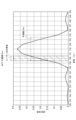
図2は、体積ホログラム30の波長選択性が非常に高い場合の波長に対する回折効率の分布を示す図である。図2の横軸は、波長を示し、縦軸は、体積ホログラム30の回折効率を示している。また、図2中で、常温における回折効率の分布を実線で示し、高温時を破線で示し、低温時を一点鎖線で示した。
図2に実線で示すように波長選択性が非常に高い体積ホログラム30は、レーザー光の帯域以外の光を殆ど回折しないことから、一見、理想的に思われる。しかし、体積ホログラム30の温度が変化すると、選択的に回折する波長が変化する。図2に示すように、高温時には、長波長側へ回折波長がシフトし、低温時には、短波長側へ回折波長がシフトする。これは、温度変化によって体積ホログラム30が膨張、又は、収縮することに起因すると考えられる。図2に示すように、高温時、低温時のいずれにおいても、体積ホログラム30が回折する波長帯域は、レーザー光の帯域から大きくずれてしまい、十分な光量の回折光を得ることができない。このような状況にあっては、体積ホログラム30を偏向部30に用いることができない。
FIG. 2 is a diagram showing the distribution of diffraction efficiency with respect to wavelength when the
The
そこで、温度変化による影響を小さくできる体積ホログラム30を開発し、体積ホログラム30を偏向部30に用いることを可能とした。
図3は、本実施形態で偏向部30に用いた体積ホログラム30の20℃における回折効率の分布の例を示す図である。
図3に例示した本実施形態の偏向部30に用いた体積ホログラム30は、分光分布曲線において半値幅が5nmとなっている。本明細書において、分光分布曲線における半値幅とは、分光分布曲線におけるピーク値の半値となるときの曲線の幅(波長範囲であり、半値全幅とも呼ぶ)である。なお、分光分布曲線の縦軸は、光量そのものであってもよいし、回折効率であってもよい。本実施形態では、回折効率の分布曲線を分光分布曲線とした。
Therefore, we have developed a
FIG. 3 is a diagram showing an example of the diffraction efficiency distribution at 20° C. of the
The
なお、分光分布曲線については、実際に回折反射されたレーザー光を測定して求めてもよいし、体積ホログラム30によって回折反射されずにそのまま透過したレーザー光を測定して求めてもよい。
The spectral distribution curve may be obtained by measuring the laser beam that is actually diffracted and reflected, or by measuring the laser beam that is transmitted through the
また、図3中には、レーザー光源10が出射するレーザー光の帯域も図2と同様に併記した。本実施形態のレーザー光源10が出射するレーザー光の帯域は、530nmを中心として波長幅が1nmである。図3に示すように、20℃では、回折効率のピーク位置とレーザー光源10が出射するレーザー光の帯域が略一致しており、効率よくレーザー光を回折反射できる。
3 also shows the band of the laser light emitted by the
図4は、本実施形態で偏向部30に用いた体積ホログラム30の40℃における回折効率の分布を示す図である。
40℃では、回折効率の分布曲線(分光分布曲線)が長波長側へ略2nmシフトするが、本実施形態の偏向部30に用いた体積ホログラム30は、分光分布曲線において半値幅が5nmとなっていることから、回折効率の低下は略半分程度に抑えられており、映像の表示が十分に可能である。
FIG. 4 is a diagram showing the diffraction efficiency distribution at 40° C. of the
At 40° C., the diffraction efficiency distribution curve (spectral distribution curve) shifts to the longer wavelength side by approximately 2 nm. Therefore, the decrease in diffraction efficiency is suppressed to approximately half, and images can be displayed satisfactorily.
図5は、本実施形態で偏向部30に用いた体積ホログラム30の0℃における回折効率の分布を示す図である。
0℃においても、回折効率の分布曲線(分光分布曲線)が短波長側へ略2nmシフトするが、本実施形態の偏向部30に用いた体積ホログラム30は、分光分布曲線において半値幅が5nmとなっていることから、回折効率の低下は略半分程度に抑えられており、映像の表示が十分に可能である。
FIG. 5 is a diagram showing the distribution of the diffraction efficiency at 0° C. of the
Even at 0° C., the diffraction efficiency distribution curve (spectral distribution curve) shifts to the short wavelength side by approximately 2 nm. Therefore, the decrease in diffraction efficiency is suppressed to approximately half, and image display is sufficiently possible.
よって、体積ホログラム30は、分光分布曲線において半値幅が5nm以上あることが望ましいといえる。
また、より好ましくは、体積ホログラム30は、分光分布曲線において半値幅が10nm以上あることが望ましい。
また、さらに好ましくは、体積ホログラム30は、分光分布曲線において半値幅が20nm以上あることが望ましい。
図6は、半値幅が5nm、10nm、20nmの回折効率の分布曲線を示す図である。
図6のように、半値幅が広くなるほど、温度変化の影響を受けにくくすることができる。
さらに、最大効率の90%の位置での波長幅が5nm以上が好ましく、10nm以上であるとさらに好ましい。中心波長がずれても効率が殆ど変わらないことから、温度変化の影響をさらに小さくすることができるからである。
Therefore, it is desirable that the
More preferably, the
More preferably, the
FIG. 6 is a diagram showing diffraction efficiency distribution curves with half widths of 5 nm, 10 nm, and 20 nm.
As shown in FIG. 6, the wider the half-value width, the less likely it is to be affected by temperature changes.
Further, the wavelength width at 90% of the maximum efficiency is preferably 5 nm or more, more preferably 10 nm or more. This is because even if the center wavelength shifts, the efficiency hardly changes, so the effect of temperature change can be further reduced.
次に、上述したように分光分布曲線において半値幅が広い体積ホログラム30のより具体的な構成について説明する。
体積ホログラム30の回折光の半値幅は、その膜厚と屈折率変調量Δnとの影響を大きく受けることが考えられるので、先ず、これらの最適な範囲を規定する。
図7は、シミュレーション条件を示す図である。図7(a)は、シミュレーション条件の一覧を示し、図7(b)は、入射角と出射角の条件を示している。
ここでは、図7に示す条件下で体積ホログラム30のシミュレーションを行い、半値幅への膜厚と屈折率変調量Δnとの影響を調べた。なお、屈折率変調量Δnについては、露光前の材料の選定、配合によって大きく変わるものであるが、露光条件によっても変化させることができるので、所望の値とすることが十分に可能である。なお、以下に示すシミュレーションの結果は、P偏光とS偏光の平均値を用いている。
Next, a more specific configuration of the
Since the half-value width of the diffracted light of the
FIG. 7 is a diagram showing simulation conditions. FIG. 7(a) shows a list of simulation conditions, and FIG. 7(b) shows the conditions of the incident angle and the outgoing angle.
Here, the
反射型ホログラムのシミュレーションは、KogelnikのCoupled Wave theory(The Bell System Technical Journal Vol.48,No.9,pp.2909-2947(Nov.1969))に基づいて行った。
反射型ホログラムの回折効率ηは、媒質での吸収が無視できる場合に、次式(A)で与えられる。
The reflection hologram was simulated based on Kogelnik's Coupled Wave theory (The Bell System Technical Journal Vol.48, No.9, pp.2909-2947 (Nov.1969)).
The diffraction efficiency η of the reflection hologram is given by the following equation (A) when the absorption in the medium can be ignored.
η=1/[1+(1-ξ2/ν2)/sinh2{√(ν2-ξ2)}]・・・(A)
ここで、νとξは次式で与えられる。
η=1/[1+(1−ξ 2 /ν 2 )/sinh 2 {√(ν 2 −ξ 2 )}] (A)
where ν and ξ are given by
ν=πtΔn/{λ√(cosθR・cosθS)}
ξ=t/2×(kRz+Kz-kSz)
ただし、
t:感光材料の厚み
λ:真空中の波長
θR:入射光とホログラム面法線ベクトルのなす角
θS:回折光とホログラム面法線ベクトルのなす角
kRz:入射光の波数ベクトルのホログラム面法線方向の成分
kSz:回折光の波数ベクトルのホログラム面法線方向の成分
Kz:回折格子ベクトルのホログラム面法線方向の成分
Δn:ホログラム媒質の屈折率変調の振幅
n:ホログラム媒質の平均屈折率
である。
ν=πtΔn/{λ√(cos θ R ·cos θ S )}
ξ=t/2×( kRz +Kz -kSz )
however,
t: Thickness of photosensitive material λ: Wavelength in vacuum θ R : Angle between incident light and hologram surface normal vector θ S : Angle between diffracted light and hologram surface normal vector k Rz : Wave vector hologram of incident light Component in the direction normal to the surface k Sz : Component of the wave vector of the diffracted light in the direction normal to the hologram surface K z : Component of the diffraction grating vector in the direction normal to the hologram surface Δn : Amplitude of refractive index modulation of the hologram medium n : Hologram medium is the average refractive index of
ここで、光の波数ベクトルkは、|k|=2πn/λで与えられ、回折格子ベクトルKは、体積ホログラムの干渉縞面に垂直なベクトルで干渉縞の周期(格子間隔)をΛとすると、|K|=2π/Λで与えられる。 Here, the wave vector k of the light is given by |k|=2πn/λ, and the diffraction grating vector K is a vector perpendicular to the interference fringe plane of the volume hologram. , |K|=2π/Λ.
(膜厚tとΔnとを変数とした半値幅シミュレーション)
図8は、膜厚tとΔnとを変化させて半値幅を求めたシミュレーションの結果をまとめた図である。図8では、膜厚tを15種類、Δnを20種類、それぞれ組み合わせて、計300種類のシミュレーションを行った結果をまとめている。
図8を見ると、膜厚tは薄い方が望ましく、Δnは高い値が望ましいことは解るが、定量的に把握することが難しい。そこで、図8に示した結果から、膜厚tとΔnとの組み合わせで好ましい範囲を数式化した。
具体的には、図8に示した半値幅は、その数値範囲で複数領域に分けることが可能であるので、境界とする半値幅が得られる膜厚tとΔnとの組み合わせからなるデータ群を集めて、そのデータ群を表す近似式を求めた。境界としては、半値幅が5nm、10nm、15nm、20nm、30nmとなる境界を設定した。
(Half width simulation with film thickness t and Δn as variables)
FIG. 8 is a diagram summarizing the results of a simulation in which the half-value width was obtained by changing the film thickness t and Δn. FIG. 8 summarizes the results of a total of 300 simulations performed by combining 15 types of film thickness t and 20 types of Δn.
As can be seen from FIG. 8, a thinner film thickness t is desirable, and a higher Δn value is desirable, but it is difficult to quantitatively grasp them. Therefore, from the results shown in FIG. 8, a preferable range of the combination of the film thickness t and .DELTA.n was formulated.
Specifically, the half-value width shown in FIG. 8 can be divided into a plurality of regions within the numerical range. We collected the data and found an approximation that represents the data group. As the boundaries, boundaries with half widths of 5 nm, 10 nm, 15 nm, 20 nm, and 30 nm were set.
図9は、半値幅から求めた膜厚tとΔnとの好ましい組み合わせ範囲を示す近似式のグラフである。
上述した境界値となる半値幅5nm、10nm、15nm、20nm、30nm毎に多項式近似を行った結果を図9中に併記した。
FIG. 9 is a graph of an approximation formula showing a preferable combination range of the film thickness t and Δn obtained from the half width.
FIG. 9 also shows the results of polynomial approximation performed for each of the half-value widths of 5 nm, 10 nm, 15 nm, 20 nm, and 30 nm, which are the boundary values described above.
半値幅5nmの近似結果から、
Δn≧-5×10⁻⁶t2+0.003t+0.0007
ただし、t≧30μmの場合には、Δn≧0.005
の関係を満たすことが望ましいといえる。この関係を満たすことにより、半値幅を5nm以上とすることができる。なお、多項式によって近似していることから、膜厚tが30μmを超えた範囲では近似式の精度が低下する。そこで、膜厚tが30μm付近では、近似曲線が略横ばいとなっていることを考慮して、t≧30μmの場合には、Δn≧0.005(Δn=0.005は、近似式にt=30μmとしたときのΔn)とした(以下の別条件でも同様)。
From the approximation result with a half width of 5 nm,
Δn≧−5×10 −6 t 2 +0.003t+0.0007
However, when t≧30 μm, Δn≧0.005
It can be said that it is desirable to satisfy the relationship of By satisfying this relationship, the half width can be 5 nm or more. Since the polynomial is used for approximation, the accuracy of the approximation is lowered in the range where the film thickness t exceeds 30 μm. Considering that the approximation curve is almost flat when the film thickness t is around 30 μm, when t≧30 μm, Δn≧0.005 (Δn=0.005 is t = Δn when 30 µm) (the same applies to other conditions below).
より望ましくは、半値幅10nmの近似結果から、
Δn≧-5×10⁻⁸t4+3×10⁻⁶t3-6×10⁻⁵t2+0.001t+4×10⁻⁵
ただし、t≧30μmの場合には、Δn≧0.015
の関係を満たすことが望ましいといえる。この関係を満たすことにより、半値幅を10nm以上とすることができる。
More desirably, from the approximation result with a half width of 10 nm,
Δn≧−5×10 −8 t 4 +3×10 −6 t 3 −6×10 −5 t 2 +0.001 t+4×10 −5
However, when t≧30 μm, Δn≧0.015
It can be said that it is desirable to satisfy the relationship of By satisfying this relationship, the half width can be 10 nm or more.
より望ましくは、半値幅15nmの近似結果から、
Δn≧1×10⁻⁷t4-6×10⁻⁶t3+5×10⁻⁵t2+0.0021t-0.0012
ただし、t≧30μmの場合には、Δn≧0.03
の関係を満たすことが望ましいといえる。この関係を満たすことにより、半値幅を15nm以上とすることができる。
More desirably, from the approximation result with a half width of 15 nm,
Δn≧1×10 −7 t 4 −6×10 −6 t 3 +5×10 −5 t 2 +0.0021 t−0.0012
However, when t≧30 μm, Δn≧0.03
It can be said that it is desirable to satisfy the relationship of By satisfying this relationship, the half width can be 15 nm or more.
より望ましくは、半値幅20nmの近似結果から、
Δn≧1×10⁻⁸t4+4×10⁻⁶t3-0.0002t2+0.0056t-0.0045
ただし、t≧30μmの場合には、Δn≧0.04
の関係を満たすことが望ましいといえる。この関係を満たすことにより、半値幅を20nm以上とすることができる。
More desirably, from the approximation result with a half width of 20 nm,
Δn≧1×10 −8 t 4 +4×10 −6 t 3 −0.0002t 2 +0.0056t−0.0045
However, when t≧30 μm, Δn≧0.04
It can be said that it is desirable to satisfy the relationship of By satisfying this relationship, the half width can be 20 nm or more.
より望ましくは、半値幅30nmの近似結果から、
Δn≧2×10⁻⁸t5-2×10⁻⁶t4+9×10⁻⁵t3-0.0019t2+0.0195t-0.0169
ただし、t≧30μmの場合には、Δn≧0.06
の関係を満たすことが望ましいといえる。この関係を満たすことにより、半値幅を30nm以上とすることができる。
More desirably, from the approximation result with a half width of 30 nm,
Δn≧2×10 −8 t 5 −2×10 −6 t 4 +9×10 −5 t 3 −0.0019 t 2 +0.0195 t−0.0169
However, when t≧30 μm, Δn≧0.06
It can be said that it is desirable to satisfy the relationship of By satisfying this relationship, the half width can be 30 nm or more.
(膜厚tとΔnとを変数とした回折効率シミュレーション)
膜厚t及びΔnが変わると、上述した半値幅のみならず、回折効率も影響を受ける。そこで、回折効率を考慮して、膜厚tとΔnとの適切な範囲をさらに限定する。
図10は、膜厚tとΔnとを変化させて回折効率の最大値を求めたシミュレーションの結果をまとめた図である。図10についても、図8の場合と同様に膜厚tを15種類、Δnを20種類、それぞれ組み合わせて、計300種類のシミュレーションを行った結果をまとめている。
図10を見ると、膜厚tは厚い方が望ましく、Δnは高い値が望ましいことは解るが、定量的に把握することが難しい。そこで、図8の場合と同様に、図10に示した結果から、膜厚tとΔnとの組み合わせで好ましい範囲を数式化した。
具体的には、境界としては、回折効率の最大値が0.2、0.4、0.6、0.8となる境界を設定した。
(Diffraction efficiency simulation with film thickness t and Δn as variables)
When the film thickness t and Δn are changed, not only the half-value width described above but also the diffraction efficiency is affected. Therefore, considering the diffraction efficiency, the appropriate range of the film thickness t and Δn is further limited.
FIG. 10 is a diagram summarizing the results of a simulation in which the maximum value of diffraction efficiency was obtained by changing the film thickness t and Δn. As in the case of FIG. 8, FIG. 10 summarizes the results of a total of 300 simulations performed by combining 15 types of film thickness t and 20 types of Δn.
As can be seen from FIG. 10, a thicker film thickness t is desirable, and a higher Δn value is desirable, but it is difficult to grasp them quantitatively. Therefore, as in the case of FIG. 8, a preferable range of the combination of the film thickness t and Δn was formulated from the results shown in FIG.
Specifically, the boundaries were set such that the maximum value of the diffraction efficiency was 0.2, 0.4, 0.6, and 0.8.
図11は、回折効率の最大値から求めた膜厚tとΔnとの好ましい組み合わせ範囲を示す近似式のグラフである。
上述した境界値となる回折効率の最大値0.2、0.4、0.6、0.8毎に多項式近似を行った結果を図11中に併記した。
FIG. 11 is a graph of an approximation formula showing a preferable combination range of the film thickness t and Δn obtained from the maximum value of the diffraction efficiency.
FIG. 11 also shows the results of polynomial approximation for each of the maximum diffraction efficiency values of 0.2, 0.4, 0.6, and 0.8, which are the boundary values described above.
回折効率の最大値0.2の近似結果から、
Δn≧0.0641t(-1.049)
の関係を満たすことが望ましいといえる。この関係を満たすことにより、回折効率の最大値を0.2以上とすることができる。
From the approximation result of the maximum diffraction efficiency of 0.2,
Δn ≧ 0.0641t (−1.049)
It can be said that it is desirable to satisfy the relationship of By satisfying this relationship, the maximum diffraction efficiency can be 0.2 or more.
より望ましくは、回折効率の最大値0.4の近似結果から、
Δn≧0.1297t(-1.065)
の関係を満たすことが望ましいといえる。この関係を満たすことにより、回折効率の最大値を0.4以上とすることができる。
More preferably, from the approximation result of the maximum diffraction efficiency of 0.4,
Δn ≧ 0.1297t (−1.065)
It can be said that it is desirable to satisfy the relationship of By satisfying this relationship, the maximum value of the diffraction efficiency can be 0.4 or more.
より望ましくは、回折効率の最大値0.6の近似結果から、
Δn≧0.1768t(-1.07)
の関係を満たすことが望ましいといえる。この関係を満たすことにより、回折効率の最大値を0.6以上とすることができる。
More preferably, from the approximation result of the maximum diffraction efficiency of 0.6,
Δn ≧ 0.1768t (−1.07)
It can be said that it is desirable to satisfy the relationship of By satisfying this relationship, the maximum diffraction efficiency can be 0.6 or more.
より望ましくは、回折効率の最大値0.8の近似結果から、
Δn≧0.257t(-1.051)
の関係を満たすことが望ましいといえる。この関係を満たすことにより、回折効率の最大値を0.8以上とすることができる。
More preferably, from the approximation result of the maximum diffraction efficiency of 0.8,
Δn ≧ 0.257t (−1.051)
It can be said that it is desirable to satisfy the relationship of By satisfying this relationship, the maximum value of diffraction efficiency can be 0.8 or more.
(入射角θ1と出射角θ2とを変数とした半値幅シミュレーション)
上述したシミュレーションは、入射角と出射角とをそれぞれ、50°と180°とに固定したものであった。この入射角50°及び出射角180°は、ヘッドマウント型の網膜走査型表示装置1を想定すると、最も好適な組み合わせである。しかし、当然ながら入射角と出射角との組み合わせは、これに限らず、適宜設計変更可能である。そこで、入射角及び出射角が変わった場合を想定してシミュレーションを行った。
(Half width simulation with the incident angle θ 1 and the output angle θ 2 as variables)
In the simulations described above, the incident and exit angles were fixed at 50° and 180°, respectively. This 50° incident angle and 180° outgoing angle are the most suitable combination, assuming the head-mounted retinal
図12は、入射角と出射角に着目したシミュレーション条件を示す図である。図12(a)は、シミュレーション条件の一覧を示し、図12(b)は、入射角θ1と出射角θ2とを変化させる状態を示している。
ここでは、図12に示す条件下で体積ホログラム30のシミュレーションを行い、半値幅への入射角θ1と出射角θ2との影響を調べた。
FIG. 12 is a diagram showing simulation conditions focusing on the incident angle and the outgoing angle. FIG. 12(a) shows a list of simulation conditions, and FIG. 12(b) shows a state in which the incident angle θ1 and the outgoing angle θ2 are changed.
Here, the
図13は、入射角θ1と出射角θ2とを変化させて半値幅を求めたシミュレーションの結果をまとめた図である。図13では、入射角θ1を0°から85°まで18種類、出射角θ2を100°から260°まで17種類、それぞれ組み合わせて、計306種類のシミュレーションを行った結果をまとめている。
図13を見ると、入射角θ1は、大きい方が(85°に近い方が)半値幅を広くでき、出射角θ2は、小さい方が(100°に近い方が)半値幅を広くできることは解るが、定量的に把握することが難しい。そこで、図13に示した結果から、入射角θ1と出射角θ2との組み合わせで好ましい範囲を先に説明した膜厚tとΔnとの場合と同様にして数式化した。境界としては、半値幅が15nm、18nmとなる境界を設定したが、半値幅15nmについては図13を見て解るように、出射角θ2が小さい側と大きい側との2領域に分かれて存在している。よって、半値幅が15nmを境界とする近似式は、2つとしている。
FIG. 13 is a diagram summarizing the results of a simulation in which the half-value width was obtained by changing the incident angle θ1 and the output angle θ2 . FIG. 13 summarizes the results of a total of 306 simulations performed by combining 18 types of incident angle θ 1 from 0° to 85° and 17 types of output angle θ 2 from 100° to 260°.
Looking at FIG. 13, the larger the incident angle θ 1 (closer to 85°), the wider the half-value width, and the smaller the output angle θ 2 (closer to 100°), the wider the half-value width. I understand that it can be done, but it is difficult to grasp it quantitatively. Therefore, from the results shown in FIG. 13, a preferable range for the combination of the incident angle .theta.1 and the outgoing angle .theta.2 was mathematically expressed in the same manner as the case of the film thickness t and .DELTA.n described above. As the boundaries, the boundaries with half-value widths of 15 nm and 18 nm were set, but as can be seen from FIG . are doing. Therefore, there are two approximation formulas with the half-value width of 15 nm as the boundary.
図14は、半値幅から求めた膜厚tとΔnとの好ましい組み合わせ範囲を示す近似式のグラフである。
上述した境界値となる半値幅15nmを2つ(15nm-A、15nm-B)と、18nmのそれぞれに多項式近似を行った結果を図14中に併記した。
FIG. 14 is a graph of an approximation formula showing a preferable combination range of the film thickness t and Δn obtained from the half width.
FIG. 14 also shows the results of polynomial approximation for two half-value widths of 15 nm (15 nm-A and 15 nm-B) and 18 nm, which are the boundary values described above.
半値幅15nmの結果から、0°≦θ1≦85°、かつ、100°≦θ2≦260°の範囲内において、
θ2≦0.3214θ1+234.75
かつ
θ2≧-θ1+118.33
の双方の関係を満たすことが望ましいといえる。この関係を満たすことにより、半値幅を15nm以上とすることができる。
From the result of the half width of 15 nm, within the ranges of 0° ≤ θ 1 ≤ 85° and 100° ≤ θ 2 ≤ 260°,
θ 2 ≦0.3214 θ 1 +234.75
and θ 2 ≧−θ 1 +118.33
It can be said that it is desirable to satisfy both relationships. By satisfying this relationship, the half width can be 15 nm or more.
また、半値幅18nmの結果から、
θ2≧160°の場合は、
θ2≦82.436θ1
(0.2278)
を満たすことが望ましい。
また、θ2<160°の場合は、
θ1≧40°
の関係を満たすことが望ましい。
これらの関係を満たすことにより、半値幅を18nm以上とすることができる。
Also, from the result of the half width of 18 nm,
If θ 2 ≧160°,
θ 2 ≤ 82.436 θ 1 (0.2278)
It is desirable to satisfy
Moreover, when θ 2 <160°,
θ 1 ≧40°
It is desirable to satisfy the relationship of
By satisfying these relationships, the half width can be 18 nm or more.
(入射角θ1と出射角θ2とを変数とした回折効率シミュレーション)
入射角θ1及び出射角θ2が変わると、上述した半値幅のみならず、回折効率も影響を受ける。そこで、回折効率を考慮して、入射角θ1と出射角θ2との適切な範囲をさらに限定する。
図15は、入射角θ1と出射角θ2とを変化させて回折効率の最大値を求めたシミュレーションの結果をまとめた図である。図15についても、図13の場合と同様に入射角θ1を0°から85°まで18種類、出射角θ2を100°から260°まで17種類、それぞれ組み合わせて、計306種類のシミュレーションを行った結果をまとめている。
図15を見ると、入射角θ1は小さい方(0°に近い方が)が望ましく、出射角θ2は大きい方(260°に近い方が)が望ましいことは解るが、定量的に把握することが難しい。そこで、図13の場合と同様に、図15に示した結果から、入射角θ1と出射角θ2との組み合わせで好ましい範囲を数式化した。
具体的には、境界としては、回折効率の最大値が0.6、0.8となる境界を設定した。
(Diffraction Efficiency Simulation with Incident Angle θ1 and Output Angle θ2 as Variables)
When the incident angle θ 1 and the exit angle θ 2 change, not only the half-value width mentioned above but also the diffraction efficiency is affected. Therefore, considering the diffraction efficiency, the appropriate range of the incident angle θ1 and the output angle θ2 is further limited.
FIG. 15 is a diagram summarizing the results of a simulation in which the maximum value of the diffraction efficiency was obtained by changing the incident angle θ1 and the output angle θ2 . 15, 18 types of incident angle θ1 from 0° to 85° and 17 types of output angle θ2 from 100° to 260° were combined in the same manner as in FIG. 13, for a total of 306 types of simulations. I am summarizing the results.
Looking at FIG. 15, it can be seen that a smaller incident angle θ1 (closer to 0°) is desirable, and a larger outgoing angle θ2 (closer to 260°) is desirable. difficult to do Therefore, as in the case of FIG. 13, from the results shown in FIG. 15, a preferable range of the combination of the incident angle θ1 and the output angle θ2 was mathematically expressed.
Specifically, the boundaries were set such that the maximum values of the diffraction efficiency were 0.6 and 0.8.
図16は、回折効率の最大値から求めた入射角θ1と出射角θ2との好ましい組み合わせ範囲を示す近似式のグラフである。
上述した境界値となる回折効率の最大値0.6、0.8のそれぞれに多項式近似を行った結果を図16中に併記した。
FIG. 16 is a graph of an approximation formula showing a preferable combination range of the incident angle θ 1 and the output angle θ 2 obtained from the maximum value of the diffraction efficiency.
FIG. 16 also shows the result of performing polynomial approximation on the maximum diffraction efficiency values of 0.6 and 0.8, which are the boundary values described above.
回折効率の最大値0.6の近似結果から、0°≦θ1≦85°、かつ、100°≦θ2≦260°の範囲内において、
θ2≧65.549ln(θ1)-170.32
の関係を満たすことが望ましいといえる。この関係を満たすことにより、回折効率の最大値を0.6以上とすることができる。
From the approximation result of the maximum diffraction efficiency value of 0.6, within the ranges of 0° ≤ θ 1 ≤ 85° and 100° ≤ θ 2 ≤ 260°,
θ 2 ≧65.549ln(θ 1 )−170.32
It can be said that it is desirable to satisfy the relationship of By satisfying this relationship, the maximum diffraction efficiency can be 0.6 or more.
より望ましくは、回折効率の最大値0.8の近似結果から、0°≦θ1≦85°、かつ、100°≦θ2≦260°の範囲内において、
θ2≧41.648ln(θ1)-28.802
の関係を満たすことが望ましいといえる。この関係を満たすことにより、回折効率の最大値を0.8以上とすることができる。
More preferably, within the ranges of 0° ≤ θ 1 ≤ 85° and 100° ≤ θ 2 ≤ 260° from the approximation result of the maximum diffraction efficiency value of 0.8,
θ 2 ≧41.648ln(θ 1 )−28.802
It can be said that it is desirable to satisfy the relationship of By satisfying this relationship, the maximum value of diffraction efficiency can be 0.8 or more.
本実施形態で偏向部30に用いる体積ホログラム30としては、上述した膜厚t及びΔnの好ましい範囲、及び、入射角θ1及び出射角θ2の好ましい範囲から、適宜組み合わせて使用条件に最適な体積ホログラム30を用いることができる。
なお、実際に作製された体積ホログラムについて、膜厚の測定を行うには、断面のSEM観察より測定するとよい。また、Δnの測定方法としては膜厚、回折角度、波長の測定結果を元にした回折効率のシミュレーション演算を行い、回折効率測定結果とのフィッティングからΔnを算出するとよい。
As for the
In order to measure the film thickness of an actually produced volume hologram, it is preferable to observe the cross section with an SEM. As a method for measuring Δn, simulation calculation of diffraction efficiency is performed based on measurement results of film thickness, diffraction angle, and wavelength, and Δn is calculated from fitting with the measurement result of diffraction efficiency.
以上説明したように、本実施形態の網膜走査型表示装置1は、偏向部30に体積ホログラム30を用いており、その回折光の半値幅が5nm以上となっているので、温度変化による回折効率の低下を抑えることができる。また、本実施形態の偏向部30に用いている体積ホログラム30は、上述した膜厚t及びΔnの好ましい範囲、及び、入射角θ1及び出射角θ2の好ましい範囲にあるので、半値幅が広く、かつ、回折効率の良好な体積ホログラム30を実現できており、温度変化によらず、適切な表示を実現可能である。
なお、波長530nmの緑の波長に対してシミュレーションを行ったが、赤及び青色の光に対しても同様に考えることができる。
As described above, the retinal
Although the simulation was performed with respect to the green wavelength of 530 nm, the same consideration can be applied to red and blue light.
(第2実施形態)
図17は、第2実施形態の頭部装着型表示装置2を示す図である。
本発明の体積ホログラム30は、第1実施形態に示した網膜走査型表示装置1に限らず、他の形態の頭部装着型表示装置にも用いることができる。
図17に示した頭部装着型表示装置2は、マイクロディスプレイ40から投影される映像光を体積ホログラム30によって偏向させて観察者の眼Eへ向けて回折反射させる。マイクロディスプレイ40は、レーザー光源を用いた光学エンジンである。
体積ホログラム30は、第1実施形態の体積ホログラム30と同様の構成とすることができる。なお、第2実施形態の体積ホログラム30は、曲面ハーフミラーと同等な光を偏向させる作用を有しており、映像光を回折反射するだけでなく、背景を透過して観察可能とする偏向部である。
(Second embodiment)
FIG. 17 is a diagram showing the head-mounted
The
In the head-mounted
The
(第3実施形態)
図18は、第3実施形態の頭部装着型表示装置3を示す図である。
第3実施形態の頭部装着型表示装置3は、レーザー光の走査を行わない網膜投影型の表示装置である。
レーザー光源50を出射したレーザー光は、コリメーターレンズ60によりコリメートされたのち、LCD(liquid crystal display)70を透過し、さらに高次回折除去光学系80により不要な回折光の除去が行われ、体積ホログラム30へ到達する。
第3実施形態の体積ホログラム30も、第1実施形態の体積ホログラム30と同様な構成とすることができ、曲面ハーフミラーと同等な光を偏向させる作用を有しており、映像光を回折反射するだけでなく、背景を透過して観察可能とする偏向部である。
(Third embodiment)
FIG. 18 is a diagram showing the head-mounted
The head-mounted
The laser light emitted from the
The
(変形形態)
以上説明した実施形態に限定されることなく、種々の変形や変更が可能であって、それらも本発明の範囲内である。
(deformed form)
Various modifications and changes are possible without being limited to the embodiments described above, and they are also within the scope of the present invention.
(1)各実施形態において、単一の波長について説明を行ったが、例えば、RGBの3色に対応したレーザー光を用いる等、波長が複数ある場合にも、本発明を適用可能である。その場合、RGB各波長に対してホログラム層を別に形成し積層してもよいし、同一層にRGB各波長の干渉縞を形成してもよい。 (1) In each embodiment, a single wavelength has been described, but the present invention can also be applied when there are multiple wavelengths, such as using laser light corresponding to the three colors of RGB. In that case, separate hologram layers may be formed and stacked for each of the RGB wavelengths, or interference fringes for each of the RGB wavelengths may be formed in the same layer.
(2)各実施形態において、望ましい範囲と規定した各数値範囲については、体積ホログラムの全領域において満たさなくてもよい。例えば、体積ホログラムに対する入射角や出射角については、体積ホログラムの全領域において望ましい数値範囲を満たさなくてもよい。例えば、視線の中心(体積ホログラムの中心)が今回規定している角度範囲の条件を満たすとよい。 (2) In each embodiment, each numerical range defined as a desirable range may not be satisfied in the entire area of the volume hologram. For example, the angle of incidence and the angle of emergence with respect to the volume hologram may not satisfy the desired numerical range over the entire area of the volume hologram. For example, it is preferable that the center of the line of sight (the center of the volume hologram) satisfies the conditions of the angle range defined this time.
(3)各実施形態において、体積ホログラム30を頭部装着型表示装置に適用した例を挙げて説明した。これに限らず、例えば、頭部に装着しない表示装置に本発明の体積ホログラムを用いてもよい。
(3) In each embodiment, an example in which the
なお、実施形態及び変形形態は、適宜組み合わせて用いることもできるが、詳細な説明は省略する。また、本発明は以上説明した各実施形態によって限定されることはない。 Although the embodiments and modifications can be used in combination as appropriate, detailed description thereof will be omitted. Moreover, the present invention is not limited to each embodiment described above.
1 網膜走査型表示装置
10 レーザー光源
20 走査部
30 偏向部、体積ホログラム
1 retinal
Claims (8)
分光分布曲線において半値幅が20nm以上であり、
当該体積ホログラムの膜厚をt(μm)、屈折率変調量をΔnとしたときに、
Δn≧1×10 -8 t 4 +4×10 -6 t 3 -0.0002t 2 +0.0056t-0.0045
ただし、t≧30μmの場合には、Δn≧0.04
の関係を満たし、
Δn≧0.1297t (-1.065)
の関係を満たす、体積ホログラム。 A volume hologram used as a deflection unit for deflecting image light of an optical engine using a laser light source,
The spectral distribution curve has a half width of 20 nm or more ,
When the film thickness of the volume hologram is t (μm) and the refractive index modulation amount is Δn,
Δn≧1×10 −8 t 4 +4×10 −6 t 3 −0.0002t 2 +0.0056t−0.0045
However, when t≧30 μm, Δn≧0.04
satisfy the relationship of
Δn≧0.1297t (−1.065)
A volume hologram that satisfies the relationship of
分光分布曲線において半値幅が20nm以上であり、
当該体積ホログラムの膜厚をt(μm)、屈折率変調量をΔnとしたときに、
Δn≧1×10 -8 t 4 +4×10 -6 t 3 -0.0002t 2 +0.0056t-0.0045
ただし、t≧30μmの場合には、Δn≧0.04
の関係を満たし、
Δn≧0.1297t (-1.065)
の関係を満たす、体積ホログラム。 A volume hologram used as a deflection unit for deflecting the direction of the scanned laser light used in a retinal scanning display device that scans the laser light from the laser light source and directly draws on the retina,
The spectral distribution curve has a half width of 20 nm or more ,
When the film thickness of the volume hologram is t (μm) and the refractive index modulation amount is Δn,
Δn≧1×10 −8 t 4 +4×10 −6 t 3 −0.0002t 2 +0.0056t−0.0045
However, when t≧30 μm, Δn≧0.04
satisfy the relationship of
Δn≧0.1297t (−1.065)
A volume hologram that satisfies the relationship of
当該体積ホログラムへ入射角θ1で入射したレーザー光の出射角をθ2としたときに、
0°≦θ1≦85°、かつ、100°≦θ2≦260°の範囲内において、
θ2≦0.3214θ1+234.75
、かつ、
θ2≧-θ1+118.33
の双方の関係を満たすこと、
を特徴とする体積ホログラム。 In the volume hologram according to claim 1 or claim 2 ,
When the emission angle of the laser beam incident on the volume hologram at the incident angle θ 1 is θ 2 ,
Within the ranges of 0° ≤ θ 1 ≤ 85° and 100° ≤ θ 2 ≤ 260°,
θ 2 ≦0.3214 θ 1 +234.75
,and,
θ 2 ≧−θ 1 +118.33
satisfying the relationship between
A volume hologram characterized by
θ2≧160°の場合は、
θ2≦82.436θ1(0.2278)
の関係を満たすこと、
を特徴とする体積ホログラム。 In the volume hologram according to claim 3 ,
If θ 2 ≧160°,
θ 2 ≤ 82.436 θ 1 (0.2278)
satisfying the relationship of
A volume hologram characterized by
θ2<160°の場合は、
θ1≧40°
の関係を満たすこと、
を特徴とする体積ホログラム。 In the volume hologram according to claim 3 ,
If θ 2 <160°, then
θ 1 ≧40°
satisfying the relationship of
A volume hologram characterized by
当該体積ホログラムへ入射角θ1で入射したレーザー光の出射角をθ2としたときに、
0°≦θ1≦85°、かつ、100°≦θ2≦260°の範囲内において、
θ2≧65.549ln(θ1)-170.32
の関係を満たすこと、
を特徴とする体積ホログラム。 In the volume hologram according to any one of claims 1 to 5 ,
When the emission angle of the laser beam incident on the volume hologram at the incident angle θ 1 is θ 2 ,
Within the ranges of 0° ≤ θ 1 ≤ 85° and 100° ≤ θ 2 ≤ 260°,
θ 2 ≧65.549ln(θ 1 )−170.32
satisfying the relationship of
A volume hologram characterized by
前記偏向部は、透明な部材に設けられてシースルーの視界に表示を重ねて観察可能な頭部装着型表示装置。 including the volume hologram according to any one of claims 1 to 6 in a deflection unit,
The head-mounted display device, wherein the deflection unit is provided on a transparent member so that the display can be superimposed on a see-through field of view and observed.
Priority Applications (1)
| Application Number | Priority Date | Filing Date | Title |
|---|---|---|---|
| JP2019102340A JP7310316B2 (en) | 2019-05-31 | 2019-05-31 | volume hologram, retinal scanning display, head-mounted display |
Applications Claiming Priority (1)
| Application Number | Priority Date | Filing Date | Title |
|---|---|---|---|
| JP2019102340A JP7310316B2 (en) | 2019-05-31 | 2019-05-31 | volume hologram, retinal scanning display, head-mounted display |
Publications (2)
| Publication Number | Publication Date |
|---|---|
| JP2020197583A JP2020197583A (en) | 2020-12-10 |
| JP7310316B2 true JP7310316B2 (en) | 2023-07-19 |
Family
ID=73648293
Family Applications (1)
| Application Number | Title | Priority Date | Filing Date |
|---|---|---|---|
| JP2019102340A Active JP7310316B2 (en) | 2019-05-31 | 2019-05-31 | volume hologram, retinal scanning display, head-mounted display |
Country Status (1)
| Country | Link |
|---|---|
| JP (1) | JP7310316B2 (en) |
Citations (8)
| Publication number | Priority date | Publication date | Assignee | Title |
|---|---|---|---|---|
| WO2009133698A1 (en) | 2008-04-30 | 2009-11-05 | パナソニック株式会社 | Scanning image display device, eyeglasses-style head-mount display, and automobile |
| JP2010055107A (en) | 2009-11-30 | 2010-03-11 | Sony Corp | Image display |
| JP2011203508A (en) | 2010-03-25 | 2011-10-13 | Panasonic Corp | Transmissive display device |
| WO2013057799A1 (en) | 2011-10-19 | 2013-04-25 | パイオニア株式会社 | Display device, head-mounted display, display method and display program |
| JP2014026116A (en) | 2012-07-26 | 2014-02-06 | Dainippon Printing Co Ltd | Photosensitive resin composition for volume hologram recording, photosensitive substrate for volume hologram recording, and volume hologram recording material |
| JP2016517036A (en) | 2013-03-25 | 2016-06-09 | エコール・ポリテクニーク・フェデラル・ドゥ・ローザンヌ(ウペエフエル)Ecole Polytechnique Federale de Lausanne (EPFL) | Method and apparatus for a multiple exit pupil head mounted display |
| JP2018084725A (en) | 2016-11-25 | 2018-05-31 | セイコーエプソン株式会社 | Display unit |
| US20180307046A1 (en) | 2017-04-19 | 2018-10-25 | Thalmic Labs Inc. | Systems, devices, and methods for holographic optical elements |
-
2019
- 2019-05-31 JP JP2019102340A patent/JP7310316B2/en active Active
Patent Citations (9)
| Publication number | Priority date | Publication date | Assignee | Title |
|---|---|---|---|---|
| WO2009133698A1 (en) | 2008-04-30 | 2009-11-05 | パナソニック株式会社 | Scanning image display device, eyeglasses-style head-mount display, and automobile |
| JP2010055107A (en) | 2009-11-30 | 2010-03-11 | Sony Corp | Image display |
| JP2011203508A (en) | 2010-03-25 | 2011-10-13 | Panasonic Corp | Transmissive display device |
| WO2013057799A1 (en) | 2011-10-19 | 2013-04-25 | パイオニア株式会社 | Display device, head-mounted display, display method and display program |
| JP2014026116A (en) | 2012-07-26 | 2014-02-06 | Dainippon Printing Co Ltd | Photosensitive resin composition for volume hologram recording, photosensitive substrate for volume hologram recording, and volume hologram recording material |
| JP2016517036A (en) | 2013-03-25 | 2016-06-09 | エコール・ポリテクニーク・フェデラル・ドゥ・ローザンヌ(ウペエフエル)Ecole Polytechnique Federale de Lausanne (EPFL) | Method and apparatus for a multiple exit pupil head mounted display |
| US20170293147A1 (en) | 2013-03-25 | 2017-10-12 | Intel Corporation | Method and apparatus for head worn display with multiple exit pupils |
| JP2018084725A (en) | 2016-11-25 | 2018-05-31 | セイコーエプソン株式会社 | Display unit |
| US20180307046A1 (en) | 2017-04-19 | 2018-10-25 | Thalmic Labs Inc. | Systems, devices, and methods for holographic optical elements |
Also Published As
| Publication number | Publication date |
|---|---|
| JP2020197583A (en) | 2020-12-10 |
Similar Documents
| Publication | Publication Date | Title |
|---|---|---|
| JP2873126B2 (en) | Photosensitive composition for volume hologram recording | |
| CA2350748A1 (en) | Head mounted apparatus for viewing an image | |
| JP5942736B2 (en) | Hologram recording material and hologram recording medium | |
| JP7468544B2 (en) | Holographic recording composition, holographic recording medium, hologram, and optical device and optical component using the same | |
| WO2014030711A1 (en) | Photosensitive composition for volume hologram recording, photosensitive substrate for volume hologram recording, and volume hologram-recorded object | |
| CN107533318B (en) | Hologram recording composition, hologram recording medium, and method for producing hologram recording medium | |
| JP2023534472A (en) | Nanoparticle-based holographic photopolymer materials and related applications | |
| JP2017203908A (en) | Holographic optical element and method for producing the same | |
| JP6064607B2 (en) | Photosensitive composition for volume hologram recording, volume hologram recording body, and method for producing volume hologram recording body | |
| JP2014026116A (en) | Photosensitive resin composition for volume hologram recording, photosensitive substrate for volume hologram recording, and volume hologram recording material | |
| JP7310316B2 (en) | volume hologram, retinal scanning display, head-mounted display | |
| WO2017195877A1 (en) | Optical element and method for producing same | |
| JP2009145620A (en) | Bonded optical element, method for manufacturing bonded optical element, image display device, and head mount display | |
| JP7331556B2 (en) | Volume hologram, head-mounted sensor device | |
| JPH08160842A (en) | Photosensitive composition for three-dimensional hologram recording, recording medium using that and forming method of three-dimensional hologram | |
| JP4500532B2 (en) | Photosensitive composition for volume hologram recording and photosensitive medium for volume hologram recording | |
| JPH08101503A (en) | Photosensitive composition for three-dimensional hologram recording, recording medium using that and forming method of three-dimensional hologram | |
| JPH08101502A (en) | Photosensitive composition for three-dimensional hologram recording, recording medium using that and forming method of three-dimensional hologram | |
| JP2021173878A (en) | Volume hologram, exit pupil expansion element and head-mount type display device | |
| JPH08101500A (en) | Photosensitive composition for volume hologram recording, recording medium using the composition and volume hologram forming method | |
| WO2017110537A1 (en) | Photosensitive composition for volume hologram production, method for producing volume hologram, volume hologram and holographic optical element | |
| JP2008026845A (en) | Three-dimensional image display screen system and three-dimensional image display device using the same | |
| Legentil et al. | Development of pixelated holograms recording strategies and aging study of different holographic photopolymer mechanisms for Augmented Reality applications | |
| WO2014030712A1 (en) | Photosensitive composition for volume hologram recording, photosensitive substrate for volume hologram recording, and volume hologram-recorded object | |
| WO2017098891A1 (en) | Holographic optical element and method for producing holographic optical element |
Legal Events
| Date | Code | Title | Description |
|---|---|---|---|
| A621 | Written request for application examination |
Free format text: JAPANESE INTERMEDIATE CODE: A621 Effective date: 20220325 |
|
| A977 | Report on retrieval |
Free format text: JAPANESE INTERMEDIATE CODE: A971007 Effective date: 20230125 |
|
| A131 | Notification of reasons for refusal |
Free format text: JAPANESE INTERMEDIATE CODE: A131 Effective date: 20230221 |
|
| A521 | Request for written amendment filed |
Free format text: JAPANESE INTERMEDIATE CODE: A523 Effective date: 20230330 |
|
| TRDD | Decision of grant or rejection written | ||
| A01 | Written decision to grant a patent or to grant a registration (utility model) |
Free format text: JAPANESE INTERMEDIATE CODE: A01 Effective date: 20230606 |
|
| A61 | First payment of annual fees (during grant procedure) |
Free format text: JAPANESE INTERMEDIATE CODE: A61 Effective date: 20230619 |
|
| R150 | Certificate of patent or registration of utility model |
Ref document number: 7310316 Country of ref document: JP Free format text: JAPANESE INTERMEDIATE CODE: R150 |