JP7310010B2 - Photodetector with low dark current - Google Patents
Photodetector with low dark current Download PDFInfo
- Publication number
- JP7310010B2 JP7310010B2 JP2022513328A JP2022513328A JP7310010B2 JP 7310010 B2 JP7310010 B2 JP 7310010B2 JP 2022513328 A JP2022513328 A JP 2022513328A JP 2022513328 A JP2022513328 A JP 2022513328A JP 7310010 B2 JP7310010 B2 JP 7310010B2
- Authority
- JP
- Japan
- Prior art keywords
- region
- doped
- doping concentration
- photodetector
- substrate
- Prior art date
- Legal status (The legal status is an assumption and is not a legal conclusion. Google has not performed a legal analysis and makes no representation as to the accuracy of the status listed.)
- Active
Links
- 239000000758 substrate Substances 0.000 claims description 294
- 239000006096 absorbing agent Substances 0.000 claims description 178
- 239000002019 doping agent Substances 0.000 claims description 163
- 239000000463 material Substances 0.000 claims description 98
- 239000000969 carrier Substances 0.000 claims description 90
- 230000003287 optical effect Effects 0.000 claims description 90
- 238000010521 absorption reaction Methods 0.000 claims description 68
- 230000002745 absorbent Effects 0.000 claims description 41
- 239000002250 absorbent Substances 0.000 claims description 41
- 238000000034 method Methods 0.000 claims description 35
- 230000004044 response Effects 0.000 claims description 7
- 230000001902 propagating effect Effects 0.000 claims description 2
- 239000010410 layer Substances 0.000 description 106
- 239000011241 protective layer Substances 0.000 description 60
- 238000010586 diagram Methods 0.000 description 33
- 230000005684 electric field Effects 0.000 description 24
- 239000003990 capacitor Substances 0.000 description 16
- 230000002829 reductive effect Effects 0.000 description 16
- 239000004065 semiconductor Substances 0.000 description 16
- 230000008569 process Effects 0.000 description 14
- 238000012546 transfer Methods 0.000 description 13
- 238000004519 manufacturing process Methods 0.000 description 12
- 230000000052 comparative effect Effects 0.000 description 11
- 238000013461 design Methods 0.000 description 11
- 238000003384 imaging method Methods 0.000 description 11
- 230000008901 benefit Effects 0.000 description 10
- 230000007547 defect Effects 0.000 description 10
- 229910052732 germanium Inorganic materials 0.000 description 10
- 230000033001 locomotion Effects 0.000 description 9
- 230000002441 reversible effect Effects 0.000 description 8
- 229910052710 silicon Inorganic materials 0.000 description 8
- 230000015556 catabolic process Effects 0.000 description 7
- 238000009792 diffusion process Methods 0.000 description 7
- 229910000530 Gallium indium arsenide Inorganic materials 0.000 description 6
- 239000002131 composite material Substances 0.000 description 6
- GNPVGFCGXDBREM-UHFFFAOYSA-N germanium atom Chemical compound [Ge] GNPVGFCGXDBREM-UHFFFAOYSA-N 0.000 description 6
- 238000012986 modification Methods 0.000 description 6
- 230000004048 modification Effects 0.000 description 6
- 229910021420 polycrystalline silicon Inorganic materials 0.000 description 6
- 238000012545 processing Methods 0.000 description 6
- 239000002800 charge carrier Substances 0.000 description 5
- 238000001514 detection method Methods 0.000 description 5
- ZOXJGFHDIHLPTG-UHFFFAOYSA-N Boron Chemical compound [B] ZOXJGFHDIHLPTG-UHFFFAOYSA-N 0.000 description 4
- LEVVHYCKPQWKOP-UHFFFAOYSA-N [Si].[Ge] Chemical compound [Si].[Ge] LEVVHYCKPQWKOP-UHFFFAOYSA-N 0.000 description 4
- 230000015572 biosynthetic process Effects 0.000 description 4
- 229910052796 boron Inorganic materials 0.000 description 4
- 238000012937 correction Methods 0.000 description 4
- 229910021480 group 4 element Inorganic materials 0.000 description 4
- 229910052751 metal Inorganic materials 0.000 description 4
- 239000002184 metal Substances 0.000 description 4
- 229910005542 GaSb Inorganic materials 0.000 description 3
- 229910001218 Gallium arsenide Inorganic materials 0.000 description 3
- 229910000673 Indium arsenide Inorganic materials 0.000 description 3
- 238000006243 chemical reaction Methods 0.000 description 3
- 230000007423 decrease Effects 0.000 description 3
- 230000003247 decreasing effect Effects 0.000 description 3
- WPYVAWXEWQSOGY-UHFFFAOYSA-N indium antimonide Chemical compound [Sb]#[In] WPYVAWXEWQSOGY-UHFFFAOYSA-N 0.000 description 3
- RPQDHPTXJYYUPQ-UHFFFAOYSA-N indium arsenide Chemical compound [In]#[As] RPQDHPTXJYYUPQ-UHFFFAOYSA-N 0.000 description 3
- 239000010703 silicon Substances 0.000 description 3
- 229910052814 silicon oxide Inorganic materials 0.000 description 3
- 229910052581 Si3N4 Inorganic materials 0.000 description 2
- VYPSYNLAJGMNEJ-UHFFFAOYSA-N Silicium dioxide Chemical compound O=[Si]=O VYPSYNLAJGMNEJ-UHFFFAOYSA-N 0.000 description 2
- XUIMIQQOPSSXEZ-UHFFFAOYSA-N Silicon Chemical compound [Si] XUIMIQQOPSSXEZ-UHFFFAOYSA-N 0.000 description 2
- 229910000577 Silicon-germanium Inorganic materials 0.000 description 2
- GWEVSGVZZGPLCZ-UHFFFAOYSA-N Titan oxide Chemical compound O=[Ti]=O GWEVSGVZZGPLCZ-UHFFFAOYSA-N 0.000 description 2
- 229910045601 alloy Inorganic materials 0.000 description 2
- 239000000956 alloy Substances 0.000 description 2
- 229910021417 amorphous silicon Inorganic materials 0.000 description 2
- 230000009286 beneficial effect Effects 0.000 description 2
- 238000010276 construction Methods 0.000 description 2
- 230000008878 coupling Effects 0.000 description 2
- 238000010168 coupling process Methods 0.000 description 2
- 238000005859 coupling reaction Methods 0.000 description 2
- 238000000407 epitaxy Methods 0.000 description 2
- 229910021478 group 5 element Inorganic materials 0.000 description 2
- BHEPBYXIRTUNPN-UHFFFAOYSA-N hydridophosphorus(.) (triplet) Chemical compound [PH] BHEPBYXIRTUNPN-UHFFFAOYSA-N 0.000 description 2
- 239000007943 implant Substances 0.000 description 2
- 238000002513 implantation Methods 0.000 description 2
- 238000011065 in-situ storage Methods 0.000 description 2
- 239000011810 insulating material Substances 0.000 description 2
- 238000005468 ion implantation Methods 0.000 description 2
- 150000002739 metals Chemical class 0.000 description 2
- 238000003860 storage Methods 0.000 description 2
- 229910052727 yttrium Inorganic materials 0.000 description 2
- GYHNNYVSQQEPJS-UHFFFAOYSA-N Gallium Chemical compound [Ga] GYHNNYVSQQEPJS-UHFFFAOYSA-N 0.000 description 1
- 229910002616 GeOx Inorganic materials 0.000 description 1
- OAICVXFJPJFONN-UHFFFAOYSA-N Phosphorus Chemical group [P] OAICVXFJPJFONN-UHFFFAOYSA-N 0.000 description 1
- 229910004205 SiNX Inorganic materials 0.000 description 1
- 229910004298 SiO 2 Inorganic materials 0.000 description 1
- 230000004075 alteration Effects 0.000 description 1
- 229910052782 aluminium Inorganic materials 0.000 description 1
- PNEYBMLMFCGWSK-UHFFFAOYSA-N aluminium oxide Inorganic materials [O-2].[O-2].[O-2].[Al+3].[Al+3] PNEYBMLMFCGWSK-UHFFFAOYSA-N 0.000 description 1
- 229910052785 arsenic Inorganic materials 0.000 description 1
- RQNWIZPPADIBDY-UHFFFAOYSA-N arsenic atom Chemical compound [As] RQNWIZPPADIBDY-UHFFFAOYSA-N 0.000 description 1
- 230000003190 augmentative effect Effects 0.000 description 1
- 238000004891 communication Methods 0.000 description 1
- 150000001875 compounds Chemical class 0.000 description 1
- 230000001010 compromised effect Effects 0.000 description 1
- 230000001143 conditioned effect Effects 0.000 description 1
- 229910052802 copper Inorganic materials 0.000 description 1
- 229910052593 corundum Inorganic materials 0.000 description 1
- 229910021419 crystalline silicon Inorganic materials 0.000 description 1
- 238000005520 cutting process Methods 0.000 description 1
- 230000001419 dependent effect Effects 0.000 description 1
- 229910003460 diamond Inorganic materials 0.000 description 1
- 239000010432 diamond Substances 0.000 description 1
- 230000000694 effects Effects 0.000 description 1
- 239000007772 electrode material Substances 0.000 description 1
- 238000007667 floating Methods 0.000 description 1
- 229910052733 gallium Inorganic materials 0.000 description 1
- CJNBYAVZURUTKZ-UHFFFAOYSA-N hafnium(IV) oxide Inorganic materials O=[Hf]=O CJNBYAVZURUTKZ-UHFFFAOYSA-N 0.000 description 1
- 230000010354 integration Effects 0.000 description 1
- 230000013011 mating Effects 0.000 description 1
- 238000012544 monitoring process Methods 0.000 description 1
- -1 oxides Substances 0.000 description 1
- TWNQGVIAIRXVLR-UHFFFAOYSA-N oxo(oxoalumanyloxy)alumane Chemical compound O=[Al]O[Al]=O TWNQGVIAIRXVLR-UHFFFAOYSA-N 0.000 description 1
- 229910052698 phosphorus Inorganic materials 0.000 description 1
- 239000011574 phosphorus Substances 0.000 description 1
- 229920005591 polysilicon Polymers 0.000 description 1
- 230000006798 recombination Effects 0.000 description 1
- 238000005215 recombination Methods 0.000 description 1
- 230000035945 sensitivity Effects 0.000 description 1
- HQVNEWCFYHHQES-UHFFFAOYSA-N silicon nitride Chemical compound N12[Si]34N5[Si]62N3[Si]51N64 HQVNEWCFYHHQES-UHFFFAOYSA-N 0.000 description 1
- 239000004094 surface-active agent Substances 0.000 description 1
- 239000003826 tablet Substances 0.000 description 1
- 229910052719 titanium Inorganic materials 0.000 description 1
- 229910052721 tungsten Inorganic materials 0.000 description 1
- 238000004148 unit process Methods 0.000 description 1
- 229910001845 yogo sapphire Inorganic materials 0.000 description 1
- RUDFQVOCFDJEEF-UHFFFAOYSA-N yttrium(III) oxide Inorganic materials [O-2].[O-2].[O-2].[Y+3].[Y+3] RUDFQVOCFDJEEF-UHFFFAOYSA-N 0.000 description 1
Images


Classifications
-
- H—ELECTRICITY
- H01—ELECTRIC ELEMENTS
- H01L—SEMICONDUCTOR DEVICES NOT COVERED BY CLASS H10
- H01L31/00—Semiconductor devices sensitive to infrared radiation, light, electromagnetic radiation of shorter wavelength or corpuscular radiation and specially adapted either for the conversion of the energy of such radiation into electrical energy or for the control of electrical energy by such radiation; Processes or apparatus specially adapted for the manufacture or treatment thereof or of parts thereof; Details thereof
- H01L31/08—Semiconductor devices sensitive to infrared radiation, light, electromagnetic radiation of shorter wavelength or corpuscular radiation and specially adapted either for the conversion of the energy of such radiation into electrical energy or for the control of electrical energy by such radiation; Processes or apparatus specially adapted for the manufacture or treatment thereof or of parts thereof; Details thereof in which radiation controls flow of current through the device, e.g. photoresistors
- H01L31/10—Semiconductor devices sensitive to infrared radiation, light, electromagnetic radiation of shorter wavelength or corpuscular radiation and specially adapted either for the conversion of the energy of such radiation into electrical energy or for the control of electrical energy by such radiation; Processes or apparatus specially adapted for the manufacture or treatment thereof or of parts thereof; Details thereof in which radiation controls flow of current through the device, e.g. photoresistors characterised by at least one potential-jump barrier or surface barrier, e.g. phototransistors
- H01L31/101—Devices sensitive to infrared, visible or ultraviolet radiation
- H01L31/102—Devices sensitive to infrared, visible or ultraviolet radiation characterised by only one potential barrier or surface barrier
- H01L31/107—Devices sensitive to infrared, visible or ultraviolet radiation characterised by only one potential barrier or surface barrier the potential barrier working in avalanche mode, e.g. avalanche photodiode
- H01L31/1075—Devices sensitive to infrared, visible or ultraviolet radiation characterised by only one potential barrier or surface barrier the potential barrier working in avalanche mode, e.g. avalanche photodiode in which the active layers, e.g. absorption or multiplication layers, form an heterostructure, e.g. SAM structure
-
- H—ELECTRICITY
- H01—ELECTRIC ELEMENTS
- H01L—SEMICONDUCTOR DEVICES NOT COVERED BY CLASS H10
- H01L31/00—Semiconductor devices sensitive to infrared radiation, light, electromagnetic radiation of shorter wavelength or corpuscular radiation and specially adapted either for the conversion of the energy of such radiation into electrical energy or for the control of electrical energy by such radiation; Processes or apparatus specially adapted for the manufacture or treatment thereof or of parts thereof; Details thereof
- H01L31/0248—Semiconductor devices sensitive to infrared radiation, light, electromagnetic radiation of shorter wavelength or corpuscular radiation and specially adapted either for the conversion of the energy of such radiation into electrical energy or for the control of electrical energy by such radiation; Processes or apparatus specially adapted for the manufacture or treatment thereof or of parts thereof; Details thereof characterised by their semiconductor bodies
- H01L31/0256—Semiconductor devices sensitive to infrared radiation, light, electromagnetic radiation of shorter wavelength or corpuscular radiation and specially adapted either for the conversion of the energy of such radiation into electrical energy or for the control of electrical energy by such radiation; Processes or apparatus specially adapted for the manufacture or treatment thereof or of parts thereof; Details thereof characterised by their semiconductor bodies characterised by the material
- H01L31/0264—Inorganic materials
- H01L31/028—Inorganic materials including, apart from doping material or other impurities, only elements of Group IV of the Periodic System
- H01L31/0288—Inorganic materials including, apart from doping material or other impurities, only elements of Group IV of the Periodic System characterised by the doping material
-
- H—ELECTRICITY
- H01—ELECTRIC ELEMENTS
- H01L—SEMICONDUCTOR DEVICES NOT COVERED BY CLASS H10
- H01L27/00—Devices consisting of a plurality of semiconductor or other solid-state components formed in or on a common substrate
- H01L27/14—Devices consisting of a plurality of semiconductor or other solid-state components formed in or on a common substrate including semiconductor components sensitive to infrared radiation, light, electromagnetic radiation of shorter wavelength or corpuscular radiation and specially adapted either for the conversion of the energy of such radiation into electrical energy or for the control of electrical energy by such radiation
- H01L27/144—Devices controlled by radiation
- H01L27/146—Imager structures
- H01L27/14601—Structural or functional details thereof
- H01L27/14603—Special geometry or disposition of pixel-elements, address-lines or gate-electrodes
-
- H—ELECTRICITY
- H01—ELECTRIC ELEMENTS
- H01L—SEMICONDUCTOR DEVICES NOT COVERED BY CLASS H10
- H01L27/00—Devices consisting of a plurality of semiconductor or other solid-state components formed in or on a common substrate
- H01L27/14—Devices consisting of a plurality of semiconductor or other solid-state components formed in or on a common substrate including semiconductor components sensitive to infrared radiation, light, electromagnetic radiation of shorter wavelength or corpuscular radiation and specially adapted either for the conversion of the energy of such radiation into electrical energy or for the control of electrical energy by such radiation
- H01L27/144—Devices controlled by radiation
- H01L27/146—Imager structures
- H01L27/14601—Structural or functional details thereof
- H01L27/14609—Pixel-elements with integrated switching, control, storage or amplification elements
- H01L27/1461—Pixel-elements with integrated switching, control, storage or amplification elements characterised by the photosensitive area
-
- H—ELECTRICITY
- H01—ELECTRIC ELEMENTS
- H01L—SEMICONDUCTOR DEVICES NOT COVERED BY CLASS H10
- H01L27/00—Devices consisting of a plurality of semiconductor or other solid-state components formed in or on a common substrate
- H01L27/14—Devices consisting of a plurality of semiconductor or other solid-state components formed in or on a common substrate including semiconductor components sensitive to infrared radiation, light, electromagnetic radiation of shorter wavelength or corpuscular radiation and specially adapted either for the conversion of the energy of such radiation into electrical energy or for the control of electrical energy by such radiation
- H01L27/144—Devices controlled by radiation
- H01L27/146—Imager structures
- H01L27/14601—Structural or functional details thereof
- H01L27/1462—Coatings
-
- H—ELECTRICITY
- H01—ELECTRIC ELEMENTS
- H01L—SEMICONDUCTOR DEVICES NOT COVERED BY CLASS H10
- H01L27/00—Devices consisting of a plurality of semiconductor or other solid-state components formed in or on a common substrate
- H01L27/14—Devices consisting of a plurality of semiconductor or other solid-state components formed in or on a common substrate including semiconductor components sensitive to infrared radiation, light, electromagnetic radiation of shorter wavelength or corpuscular radiation and specially adapted either for the conversion of the energy of such radiation into electrical energy or for the control of electrical energy by such radiation
- H01L27/144—Devices controlled by radiation
- H01L27/146—Imager structures
- H01L27/14643—Photodiode arrays; MOS imagers
-
- H—ELECTRICITY
- H01—ELECTRIC ELEMENTS
- H01L—SEMICONDUCTOR DEVICES NOT COVERED BY CLASS H10
- H01L31/00—Semiconductor devices sensitive to infrared radiation, light, electromagnetic radiation of shorter wavelength or corpuscular radiation and specially adapted either for the conversion of the energy of such radiation into electrical energy or for the control of electrical energy by such radiation; Processes or apparatus specially adapted for the manufacture or treatment thereof or of parts thereof; Details thereof
- H01L31/02—Details
- H01L31/02002—Arrangements for conducting electric current to or from the device in operations
- H01L31/02005—Arrangements for conducting electric current to or from the device in operations for device characterised by at least one potential jump barrier or surface barrier
-
- H—ELECTRICITY
- H01—ELECTRIC ELEMENTS
- H01L—SEMICONDUCTOR DEVICES NOT COVERED BY CLASS H10
- H01L31/00—Semiconductor devices sensitive to infrared radiation, light, electromagnetic radiation of shorter wavelength or corpuscular radiation and specially adapted either for the conversion of the energy of such radiation into electrical energy or for the control of electrical energy by such radiation; Processes or apparatus specially adapted for the manufacture or treatment thereof or of parts thereof; Details thereof
- H01L31/02—Details
- H01L31/0224—Electrodes
- H01L31/022408—Electrodes for devices characterised by at least one potential jump barrier or surface barrier
-
- H—ELECTRICITY
- H01—ELECTRIC ELEMENTS
- H01L—SEMICONDUCTOR DEVICES NOT COVERED BY CLASS H10
- H01L31/00—Semiconductor devices sensitive to infrared radiation, light, electromagnetic radiation of shorter wavelength or corpuscular radiation and specially adapted either for the conversion of the energy of such radiation into electrical energy or for the control of electrical energy by such radiation; Processes or apparatus specially adapted for the manufacture or treatment thereof or of parts thereof; Details thereof
- H01L31/08—Semiconductor devices sensitive to infrared radiation, light, electromagnetic radiation of shorter wavelength or corpuscular radiation and specially adapted either for the conversion of the energy of such radiation into electrical energy or for the control of electrical energy by such radiation; Processes or apparatus specially adapted for the manufacture or treatment thereof or of parts thereof; Details thereof in which radiation controls flow of current through the device, e.g. photoresistors
- H01L31/10—Semiconductor devices sensitive to infrared radiation, light, electromagnetic radiation of shorter wavelength or corpuscular radiation and specially adapted either for the conversion of the energy of such radiation into electrical energy or for the control of electrical energy by such radiation; Processes or apparatus specially adapted for the manufacture or treatment thereof or of parts thereof; Details thereof in which radiation controls flow of current through the device, e.g. photoresistors characterised by at least one potential-jump barrier or surface barrier, e.g. phototransistors
- H01L31/101—Devices sensitive to infrared, visible or ultraviolet radiation
- H01L31/102—Devices sensitive to infrared, visible or ultraviolet radiation characterised by only one potential barrier or surface barrier
- H01L31/109—Devices sensitive to infrared, visible or ultraviolet radiation characterised by only one potential barrier or surface barrier the potential barrier being of the PN heterojunction type
-
- H—ELECTRICITY
- H01—ELECTRIC ELEMENTS
- H01L—SEMICONDUCTOR DEVICES NOT COVERED BY CLASS H10
- H01L31/00—Semiconductor devices sensitive to infrared radiation, light, electromagnetic radiation of shorter wavelength or corpuscular radiation and specially adapted either for the conversion of the energy of such radiation into electrical energy or for the control of electrical energy by such radiation; Processes or apparatus specially adapted for the manufacture or treatment thereof or of parts thereof; Details thereof
- H01L31/08—Semiconductor devices sensitive to infrared radiation, light, electromagnetic radiation of shorter wavelength or corpuscular radiation and specially adapted either for the conversion of the energy of such radiation into electrical energy or for the control of electrical energy by such radiation; Processes or apparatus specially adapted for the manufacture or treatment thereof or of parts thereof; Details thereof in which radiation controls flow of current through the device, e.g. photoresistors
- H01L31/10—Semiconductor devices sensitive to infrared radiation, light, electromagnetic radiation of shorter wavelength or corpuscular radiation and specially adapted either for the conversion of the energy of such radiation into electrical energy or for the control of electrical energy by such radiation; Processes or apparatus specially adapted for the manufacture or treatment thereof or of parts thereof; Details thereof in which radiation controls flow of current through the device, e.g. photoresistors characterised by at least one potential-jump barrier or surface barrier, e.g. phototransistors
- H01L31/101—Devices sensitive to infrared, visible or ultraviolet radiation
- H01L31/11—Devices sensitive to infrared, visible or ultraviolet radiation characterised by two potential barriers or surface barriers, e.g. bipolar phototransistor
- H01L31/1105—Devices sensitive to infrared, visible or ultraviolet radiation characterised by two potential barriers or surface barriers, e.g. bipolar phototransistor the device being a bipolar phototransistor
-
- Y—GENERAL TAGGING OF NEW TECHNOLOGICAL DEVELOPMENTS; GENERAL TAGGING OF CROSS-SECTIONAL TECHNOLOGIES SPANNING OVER SEVERAL SECTIONS OF THE IPC; TECHNICAL SUBJECTS COVERED BY FORMER USPC CROSS-REFERENCE ART COLLECTIONS [XRACs] AND DIGESTS
- Y02—TECHNOLOGIES OR APPLICATIONS FOR MITIGATION OR ADAPTATION AGAINST CLIMATE CHANGE
- Y02P—CLIMATE CHANGE MITIGATION TECHNOLOGIES IN THE PRODUCTION OR PROCESSING OF GOODS
- Y02P70/00—Climate change mitigation technologies in the production process for final industrial or consumer products
- Y02P70/50—Manufacturing or production processes characterised by the final manufactured product
Landscapes
- Physics & Mathematics (AREA)
- Engineering & Computer Science (AREA)
- Power Engineering (AREA)
- Electromagnetism (AREA)
- Condensed Matter Physics & Semiconductors (AREA)
- General Physics & Mathematics (AREA)
- Computer Hardware Design (AREA)
- Microelectronics & Electronic Packaging (AREA)
- Chemical & Material Sciences (AREA)
- Inorganic Chemistry (AREA)
- Light Receiving Elements (AREA)
- Solid State Image Pick-Up Elements (AREA)
Description
関連出願の相互参照
本出願は、2019年8月28日に出願された米国仮特許出願第62/892,551号、2019年9月12日に出願された米国仮特許出願第62/899,153号、2019年10月31日に出願された米国仮特許出願第62/929,089号、2020年7月20日に出願された米国仮特許出願第63/053,723号の利益を主張し、それらの特許出願は各々がその全体において本明細書に参照により組み込まれている。
CROSS-REFERENCE TO RELATED APPLICATIONS This application is based on U.S. Provisional Patent Application No. 62/892,551, filed Aug. 28, 2019, U.S. Provisional Patent Application No. 62/899, filed Sep. 12, 2019, 153, claims benefit of U.S. Provisional Patent Application No. 62/929,089 filed Oct. 31, 2019 and U.S. Provisional Patent Application No. 63/053,723 filed July 20, 2020 and each of these patent applications is incorporated herein by reference in its entirety.
光検出器が、光学信号を検出し、その光学信号を、他の回路によってさらに処理され得る電気信号へと変換するために、使用され得る。光検出器は、消費家電製品、イメージセンサ、高速光学受信器、データ通信、直接/間接飛行時間(TOF)測距または撮像センサ、医療デバイス、および多くの他の適切な用途において使用され得る。 A photodetector can be used to detect an optical signal and convert the optical signal into an electrical signal that can be further processed by other circuitry. Photodetectors can be used in consumer electronics, image sensors, high speed optical receivers, data communications, direct/indirect time-of-flight (TOF) ranging or imaging sensors, medical devices, and many other suitable applications.
本開示は概して、光検出装置、および光検出装置を備えるイメージシステムに関する。 FIELD OF THE DISCLOSURE The present disclosure relates generally to photodetectors and imaging systems comprising photodetectors.
本開示の他の実施形態によれば、光検出装置が提供される。光検出装置は、第1のピークドーピング濃度を有する第1のドーパントを含む吸収領域と、吸収領域を支持する基板とを備え、基板は、第1のピークドーピング濃度より小さい第2のピークドーピング濃度を有する第2のドーパントを含み、吸収領域は、基板の材料と異なる材料を含む。 According to another embodiment of the present disclosure, a photodetection device is provided. The photodetector comprises an absorbing region including a first dopant having a first peak doping concentration and a substrate supporting the absorbing region, the substrate having a second peak doping concentration less than the first peak doping concentration. and the absorbing region comprises a material different from the material of the substrate.
本開示の実施形態によれば、光検出装置が提供される。光検出装置は光検出デバイスを備え、光検出デバイスは、第1の表面および第2の表面を有するキャリア伝導層と、キャリア伝導層と接触しており、光学信号を受信し、光学信号に応答して光キャリアを発生させるように構成される吸収領域であって、吸収領域は、第1の伝導型および第1のピークドーピング濃度を有する第1のドーパントでドープされ、キャリア伝導層は、第2の伝導型および第2のピークドーピング濃度を有する第2のドーパントでドープされ、キャリア伝導層は、吸収領域の材料と異なる材料を含み、キャリア伝導層は、少なくとも1つのヘテロ界面を形成するために吸収領域と接触しており、吸収領域のドーピング濃度と、少なくとも1つのヘテロ界面におけるキャリア伝導領域のドーピング濃度との間の比が10以上である、吸収領域と、キャリア伝導層の同じ側の上に形成される第1の電極および第2の電極とを備える。 According to embodiments of the present disclosure, a photodetector is provided. The photodetector comprises a photodetector device having a first surface and a second surface and a carrier conducting layer in contact with the carrier conducting layer for receiving and responding to the optical signal. an absorber region configured to generate photocarriers through the absorption region, the absorber region being doped with a first dopant having a first conductivity type and a first peak doping concentration; doped with a second dopant having a conductivity type of 2 and a second peak doping concentration, the carrier conduction layer comprising a material different from the material of the absorption region, the carrier conduction layer forming at least one heterointerface; on the same side of the absorption region and the carrier conduction layer, wherein the ratio between the doping concentration of the absorption region and the doping concentration of the carrier conduction region at the at least one heterointerface is 10 or more. A first electrode and a second electrode formed thereon.
本開示の実施形態によれば、光検出装置が提供される。光検出装置は光検出デバイスを備え、光検出デバイスは、第1の表面および第2の表面を有するキャリア伝導層と、キャリア伝導層と接触しており、光学信号を受信し、光学信号に応答して光キャリアを発生させるように構成される吸収領域であって、吸収領域は、第1の伝導型および第1のピークドーピング濃度を有する第1のドーパントでドープされ、キャリア伝導層は、第2の伝導型および第2のピークドーピング濃度を有する第2のドーパントでドープされ、キャリア伝導層は、吸収領域の材料と異なる材料を含み、キャリア伝導層は、少なくとも1つのヘテロ界面を形成するために吸収領域と接触しており、吸収領域のドーピング濃度と、少なくとも1つのヘテロ界面におけるキャリア伝導領域のドーピング濃度との間の比が10以上であるか、または、吸収領域の第1のピークドーピング濃度と、キャリア伝導領域の第2のピークドーピング濃度との間の比が10以上である、吸収領域と、キャリア伝導層において、吸収領域と接触している第2のドープ領域であって、第1の伝導型と同じ伝導型を有し、第1のピークドーピング濃度より高い第4のピークドーピング濃度を有する第4のドーパントでドープされる、第2のドープ領域とを備える。 According to embodiments of the present disclosure, a photodetector is provided. The photodetector comprises a photodetector device having a first surface and a second surface and a carrier conducting layer in contact with the carrier conducting layer for receiving and responding to the optical signal. an absorber region configured to generate photocarriers through the absorption region, the absorber region being doped with a first dopant having a first conductivity type and a first peak doping concentration; doped with a second dopant having a conductivity type of 2 and a second peak doping concentration, the carrier conduction layer comprising a material different from the material of the absorption region, the carrier conduction layer forming at least one heterointerface; and the ratio between the doping concentration of the absorbing region and the doping concentration of the carrier conduction region at the at least one heterointerface is 10 or more, or the first peak doping of the absorbing region an absorber region and a second doped region in the carrier conduction layer in contact with the absorber region, wherein the ratio between the concentration and the second peak doping concentration of the carrier conduction region is greater than or equal to 10; a second doped region having the same conductivity type as the one conductivity type and doped with a fourth dopant having a fourth peak doping concentration higher than the first peak doping concentration.
本開示の実施形態によれば、光検出装置が提供される。光検出装置は光検出デバイスを備え、光検出デバイスは、第1の表面および第2の表面を有するキャリア伝導層と、キャリア伝導層と接触しており、光学信号を受信し、光学信号に応答して光キャリアを発生させるように構成される吸収領域とを備え、吸収領域は、第1の伝導型および第1のピークドーピング濃度を有する第1のドーパントでドープされ、キャリア伝導層は、第2の伝導型および第2のピークドーピング濃度を有する第2のドーパントでドープされ、キャリア伝導層は、吸収領域の材料と異なる材料を含み、キャリア伝導層は、少なくとも1つのヘテロ界面を形成するために吸収領域と接触しており、吸収領域のドーピング濃度と、少なくとも1つのヘテロ界面におけるキャリア伝導領域のドーピング濃度との間の比が10以上であり、吸収領域の第1のピークドーピング濃度と、キャリア伝導領域の第2のピークドーピング濃度との間の比が10以上であり、吸収領域の少なくとも50%は、1×1016cm-3以上の第1のドーパントのドーピング濃度でドープされる。 According to embodiments of the present disclosure, a photodetector is provided. The photodetector comprises a photodetector device having a first surface and a second surface and a carrier conducting layer in contact with the carrier conducting layer for receiving and responding to the optical signal. an absorber region configured to generate photocarriers through the absorption region, the absorber region being doped with a first dopant having a first conductivity type and a first peak doping concentration, and the carrier conducting layer comprising: doped with a second dopant having a conductivity type of 2 and a second peak doping concentration, the carrier conduction layer comprising a material different from the material of the absorption region, the carrier conduction layer forming at least one heterointerface; a first peak doping concentration of the absorbing region; The ratio between the second peak doping concentration of the carrier conduction region is 10 or greater, and at least 50% of the absorbing region is doped with a doping concentration of the first dopant of 1×10 16 cm −3 or greater.
本開示の実施形態によれば、光検出装置が提供される。光検出装置は光検出デバイスを備え、光検出デバイスは、第1の表面および第2の表面を有するキャリア伝導層と、キャリア伝導層と接触しており、光学信号を受信し、光学信号に応答して光キャリアを発生させるように構成される吸収領域であって、吸収領域は、第1の伝導型および第1のピークドーピング濃度を有する第1のドーパントでドープされ、キャリア伝導層は、第2の伝導型および第2のピークドーピング濃度を有する第2のドーパントでドープされ、キャリア伝導層は、吸収領域の材料と異なる材料を含み、キャリア伝導層は、少なくとも1つのヘテロ界面を形成するために吸収領域と接触しており、吸収領域の第1のピークドーピング濃度とキャリア伝導領域の第2のピークドーピング濃度との間の比が10以上である、吸収領域と、キャリア伝導層の第1の表面上に形成され、キャリア伝導層に電気的に結合される第1の電極であって、吸収領域から分離され、光キャリアの一部分を収集するように構成される、第1の電極と、キャリア伝導層の第1の表面上に形成され、吸収領域に電気的に結合される第2の電極とを備える。 According to embodiments of the present disclosure, a photodetector is provided. The photodetector comprises a photodetector device having a first surface and a second surface and a carrier conducting layer in contact with the carrier conducting layer for receiving and responding to the optical signal. an absorber region configured to generate photocarriers through the absorption region, the absorber region being doped with a first dopant having a first conductivity type and a first peak doping concentration; doped with a second dopant having a conductivity type of 2 and a second peak doping concentration, the carrier conduction layer comprising a material different from the material of the absorption region, the carrier conduction layer forming at least one heterointerface; an absorber region in contact with the absorber region, and a ratio between a first peak doping concentration of the absorber region and a second peak doping concentration of the carrier conduction region is greater than or equal to 10; a first electrode formed on a surface of and electrically coupled to the carrier conducting layer, the first electrode separated from the absorbing region and configured to collect a portion of the photocarriers; a second electrode formed on the first surface of the carrier conducting layer and electrically coupled to the absorbing region.
本開示の他の実施形態によれば、光検出装置が提供される。光検出装置は光検出デバイスを備え、光検出デバイスは、第1の表面および第2の表面を有する基板と、基板の第1の表面上で、光学信号を受信し、光学信号に応答して光キャリアを発生させるように構成される吸収領域であって、吸収領域は、第1の伝導型および第1のピークドーピング濃度を有する第1のドーパントでドープされ、基板は、第2の伝導型および第2のピークドーピング濃度を有する第2のドーパントでドープされ、基板は、吸収領域の材料と異なる材料を含み、基板は、少なくとも1つのヘテロ界面を形成するために吸収領域と接触しており、吸収領域の第1のピークドーピング濃度と基板の第2のピークドーピング濃度との間の比が10以上であるか、または、吸収領域のドーピング濃度と、少なくとも1つのヘテロ界面における基板のドーピング濃度との間の比が10以上である、吸収領域と、基板の第1の表面上に形成され、基板に電気的に結合される第1の電極であって、吸収領域から分離され、光キャリアの一部分を収集するように構成される、第1の電極と、基板の第1の表面上に形成され、吸収領域に電気的に結合される第2の電極とを備える。本開示の他の実施形態によれば、光検出装置が提供される。光検出装置は光検出デバイスを備え、光検出デバイスは、光学信号を受信し、光学信号に応答して光キャリアを発生させるように構成される吸収領域であって、吸収領域は、第1の伝導型および第1のピークドーピング濃度を有する第1のドーパントでドープされる、吸収領域と、吸収領域上に、第1の表面、および、第1の表面と対向する第2の表面を有する保護層であって、保護層は、第2の伝導型および第2のピークドーピング濃度を有する第2のドーパントでドープされ、保護層は、吸収領域の材料と異なる材料を含み、保護層は、少なくとも1つのヘテロ界面を形成するために吸収領域と接触しており、吸収領域の第1のピークドーピング濃度と保護層の第2のピークドーピング濃度との間の比が10以上であるか、または、吸収領域のドーピング濃度と、少なくとも1つのヘテロ界面における保護層のドーピング濃度との間の比が10以上である、保護層と、保護層の第1の表面上に形成され、保護層に電気的に結合される第1の電極であって、吸収領域から分離され、光キャリアの一部分を収集するように構成される、第1の電極と、保護層の第1の表面上に形成され、吸収領域に電気的に結合される第2の電極とを備える。 According to another embodiment of the present disclosure, a photodetection device is provided. The photodetector apparatus comprises a photodetector device having a substrate having a first surface and a second surface and receiving and responsive to the optical signal on the first surface of the substrate. An absorbing region configured to generate photocarriers, the absorbing region being doped with a first dopant having a first conductivity type and a first peak doping concentration, and a substrate having a second conductivity type. and a second dopant having a second peak doping concentration, the substrate comprising a material different from the material of the absorber region, the substrate in contact with the absorber region to form at least one heterointerface. , the ratio between the first peak doping concentration of the absorber region and the second peak doping concentration of the substrate is greater than or equal to 10, or the doping concentration of the absorber region and the doping concentration of the substrate at at least one heterointerface. and a first electrode formed on the first surface of the substrate and electrically coupled to the substrate, the first electrode being separated from the absorbing region and having a ratio between and a second electrode formed on the first surface of the substrate and electrically coupled to the absorbing region. According to another embodiment of the present disclosure, a photodetection device is provided. The photodetector apparatus comprises a photodetector device, the photodetector device being an absorbing region configured to receive an optical signal and generate photocarriers in response to the optical signal, the absorbing region comprising a first A protection having an absorbing region doped with a first dopant having a conductivity type and a first peak doping concentration, a first surface on the absorbing region, and a second surface opposite the first surface. A layer, the protective layer being doped with a second dopant having a second conductivity type and a second peak doping concentration, the protective layer comprising a material different from the material of the absorbing region, the protective layer comprising at least in contact with the absorber region to form a heterointerface, the ratio between the first peak doping concentration of the absorber region and the second peak doping concentration of the protective layer being 10 or more, or a protective layer having a ratio between the doping concentration of the absorbing region and the doping concentration of the protective layer at the at least one heterointerface of 10 or more; a first electrode separated from the absorbing region and configured to collect a portion of the photocarriers; and a first electrode formed on a first surface of the protective layer, the absorbing and a second electrode electrically coupled to the region.
本開示の他の実施形態によれば、光検出装置が提供される。光検出装置は光検出デバイスを備え、光検出デバイスは、第1の表面および第2の表面を有するキャリア伝導層と、キャリア伝導層と接触しており、光学信号を受信し、光学信号に応答して光キャリアを発生させるように構成される吸収領域であって、吸収領域は、第1の伝導型および第1のピークドーピング濃度を有する第1のドーパントでドープされ、キャリア伝導層は、第2の伝導型および第2のピークドーピング濃度を有する第2のドーパントでドープされ、キャリア伝導層は、吸収領域の材料と異なる材料を含み、キャリア伝導層は、少なくとも1つのヘテロ界面を形成するために吸収領域と接触しており、吸収領域のドーピング濃度と、少なくとも1つのヘテロ界面におけるキャリア伝導層のドーピング濃度との間の比が10以上であるか、または、吸収領域の第1のピークドーピング濃度と、キャリア伝導層の第2のピークドーピング濃度との間の比が10以上である、吸収領域と、吸収領域に電気的に結合され、キャリア伝導層に部分的に形成される1つまたは複数のスイッチであって、1つまたは複数のスイッチの各々は、第1の表面上に形成され、吸収領域から分離される制御電極および読み出し電極を備える、1つまたは複数のスイッチと、第1の表面上に形成され、吸収領域に電気的に結合される電極とを備える。 According to another embodiment of the present disclosure, a photodetection device is provided. The photodetector comprises a photodetector device having a first surface and a second surface and a carrier conducting layer in contact with the carrier conducting layer for receiving and responding to the optical signal. an absorber region configured to generate photocarriers through the absorption region, the absorber region being doped with a first dopant having a first conductivity type and a first peak doping concentration; doped with a second dopant having a conductivity type of 2 and a second peak doping concentration, the carrier conduction layer comprising a material different from the material of the absorption region, the carrier conduction layer forming at least one heterointerface; a doping concentration of the absorbing region and a doping concentration of the carrier conduction layer at the at least one heterointerface is greater than or equal to 10, or the first peak doping of the absorbing region an absorber region having a ratio between the concentration and the second peak doping concentration of the carrier conduction layer of 10 or more; a plurality of switches, each of the one or more switches comprising a control electrode and a readout electrode formed on a first surface and separated from the absorbing region; and an electrode formed on a surface of and electrically coupled to the absorbing region.
本開示の他の実施形態によれば、光検出装置が提供される。光検出装置は光検出デバイスを備え、光検出デバイスは、第1の表面および第2の表面を有するキャリア伝導層と、キャリア伝導層と接触しており、光学信号を受信し、光学信号に応答して光キャリアを発生させるように構成される吸収領域であって、吸収領域は、第1の伝導型および第1のピークドーピング濃度を有する第1のドーパントでドープされ、キャリア伝導層は、第2の伝導型および第2のピークドーピング濃度を有する第2のドーパントでドープされ、キャリア伝導層は、吸収領域の材料と異なる材料を含み、キャリア伝導層は、少なくとも1つのヘテロ界面を形成するために吸収領域と接触しており、吸収領域のドーピング濃度と、少なくとも1つのヘテロ界面におけるキャリア伝導層のドーピング濃度との間の比が10以上であるか、または、吸収領域の第1のピークドーピング濃度と、キャリア伝導層の第2のピークドーピング濃度との間の比が10以上である、吸収領域と、吸収領域に電気的に結合され、キャリア伝導層に部分的に形成される1つまたは複数のスイッチであって、1つまたは複数のスイッチの各々は、キャリア伝導層の同じ側に形成される制御電極および読み出し電極を備える、1つまたは複数のスイッチと、キャリア伝導層において、吸収領域と接触している第2のドープ領域であって、第1の伝導型と同じ伝導型を有し、第1のピークドーピング濃度より高い第4のピークドーピング濃度を有する第4のドーパントでドープされる、第2のドープ領域と、第2のドープ領域に電気的に結合される電極とを備える。 According to another embodiment of the present disclosure, a photodetection device is provided. The photodetector comprises a photodetector device having a first surface and a second surface and a carrier conducting layer in contact with the carrier conducting layer for receiving and responding to the optical signal. an absorber region configured to generate photocarriers through the absorption region, the absorber region being doped with a first dopant having a first conductivity type and a first peak doping concentration; doped with a second dopant having a conductivity type of 2 and a second peak doping concentration, the carrier conduction layer comprising a material different from the material of the absorption region, the carrier conduction layer forming at least one heterointerface; a doping concentration of the absorbing region and a doping concentration of the carrier conduction layer at the at least one heterointerface is greater than or equal to 10, or the first peak doping of the absorbing region an absorber region having a ratio between the concentration and the second peak doping concentration of the carrier conduction layer of 10 or more; a plurality of switches, each of the one or more switches comprising a control electrode and a readout electrode formed on the same side of the carrier conduction layer; a second doped region in contact with the second dopant having the same conductivity type as the first conductivity type and being doped with a fourth dopant having a fourth peak doping concentration higher than the first peak doping concentration; and an electrode electrically coupled to the second doped region.
本開示の他の実施形態によれば、光検出装置が提供される。光検出装置は光検出デバイスを備え、光検出デバイスは、第1の表面および第2の表面を有するキャリア伝導層と、キャリア伝導層と接触しており、光学信号を受信し、光学信号に応答して光キャリアを発生させるように構成される吸収領域であって、吸収領域は、第1の伝導型および第1のピークドーピング濃度を有する第1のドーパントでドープされ、キャリア伝導層は、第2の伝導型および第2のピークドーピング濃度を有する第2のドーパントでドープされ、キャリア伝導層は、吸収領域の材料と異なる材料を含み、キャリア伝導層は、少なくとも1つのヘテロ界面を形成するために吸収領域と接触しており、吸収領域のドーピング濃度と、少なくとも1つのヘテロ界面におけるキャリア伝導層のドーピング濃度との間の比が10以上であるか、または、吸収領域の第1のピークドーピング濃度と、キャリア伝導層の第2のピークドーピング濃度との間の比が10以上である、吸収領域と、吸収領域に電気的に結合され、キャリア伝導層に部分的に形成される1つまたは複数のスイッチとを備える。光検出装置は、それぞれのスイッチへと電気的に1つまたは複数の読み取り回路をさらに備え、1つまたは複数の読み取り回路は、転送トランジスタとコンデンサとの間に電圧制御トランジスタを備える。 According to another embodiment of the present disclosure, a photodetection device is provided. The photodetector comprises a photodetector device having a first surface and a second surface and a carrier conducting layer in contact with the carrier conducting layer for receiving and responding to the optical signal. an absorber region configured to generate photocarriers through the absorption region, the absorber region being doped with a first dopant having a first conductivity type and a first peak doping concentration; doped with a second dopant having a conductivity type of 2 and a second peak doping concentration, the carrier conduction layer comprising a material different from the material of the absorption region, the carrier conduction layer forming at least one heterointerface; a doping concentration of the absorbing region and a doping concentration of the carrier conduction layer at the at least one heterointerface is greater than or equal to 10, or the first peak doping of the absorbing region an absorber region having a ratio between the concentration and the second peak doping concentration of the carrier conduction layer of 10 or more; and a plurality of switches. The photodetector device further comprises one or more read circuits electrically to each switch, the one or more read circuits comprising a voltage controlled transistor between the transfer transistor and the capacitor.
本開示の他の実施形態によれば、光検出装置が提供される。光検出装置は、伝導型でドープされ、第1のピークドーピング濃度を有する第1のドーパントを含む吸収領域と、吸収領域と接触しているキャリア伝導層とを備え、キャリア伝導層は、伝導型でドープされ、第1のピークドーピング濃度より低い第2のピークドーピング濃度を有する第2のドーパントを含む伝導領域を備え、キャリア伝導層は、吸収領域の材料と異なる材料を含む、またはそのような材料から成り、伝導領域は5μm未満の深さを有する。 According to another embodiment of the present disclosure, a photodetection device is provided. The photodetector comprises an absorber region doped with a conductivity type and including a first dopant having a first peak doping concentration, and a carrier conduction layer in contact with the absorber region, the carrier conduction layer having a conductivity type and a second dopant having a second peak doping concentration lower than the first peak doping concentration, the carrier conduction layer comprising or such a material different from the material of the absorption region. material, the conductive region has a depth of less than 5 μm.
本開示の他の実施形態によれば、光検出装置が提供される。光検出装置は、第1のピークドーピング濃度を有する第1のドーパントでドープされた吸収領域と、伝導型を有する第1の接触領域と、第1の接触領域の伝導型と異なる伝導型を有する第2の接触領域と、第1の接触領域の伝導型と同じ伝導型を有し、第1の接触領域と第2の接触領域との間に一部がある電荷領域と、吸収領域を支持する基板とを備え、基板は、第1のピークドーピング濃度より小さい第2のピークドーピング濃度を有する第2のドーパントを含み、吸収領域は、基板の材料と異なる材料を含む。 According to another embodiment of the present disclosure, a photodetection device is provided. The photodetector has a first dopant doped absorber region having a first peak doping concentration, a first contact region having a conductivity type, and a conductivity type different from the conductivity type of the first contact region. supporting a second contact region, a charge region having the same conductivity type as that of the first contact region and partially between the first contact region and the second contact region, and an absorption region the substrate comprising a second dopant having a second peak doping concentration less than the first peak doping concentration, and the absorbing region comprising a material different from the material of the substrate.
本開示の他の実施形態によれば、光検出装置が提供される。光検出装置は、基板と、基板によって支持され、第1の伝導型を有する第1のドーパントでドープされた吸収領域と、第1の伝導型と異なる伝導型を各々が有し、基板に形成される複数の第1の接触領域と、吸収領域に形成され、第1の伝導型と同じ伝導型を有する第2のドープ領域と、第1の伝導型と同じ伝導型を各々が有し、基板に形成される複数の第3の接触領域とを備え、第1の接触領域は第1の平面に沿って配置され、第3の接触領域は、第1の平面と異なる第2の平面に沿って配置される。ある実施形態では、複数の増倍領域が複数の第3の接触領域と複数の第1の接触領域との間に形成される。 According to another embodiment of the present disclosure, a photodetection device is provided. A photodetector is formed in the substrate, a substrate, an absorber region supported by the substrate and doped with a first dopant having a first conductivity type, each having a conductivity type different from the first conductivity type. a plurality of first contact regions formed in the absorbing region and having the same conductivity type as the first conductivity type, each having the same conductivity type as the first conductivity type; a plurality of third contact areas formed on the substrate, the first contact areas being arranged along a first plane and the third contact areas being in a second plane different from the first plane; placed along. In some embodiments, a plurality of multiplication regions are formed between the plurality of third contact regions and the plurality of first contact regions.
本開示の他の実施形態によれば、光検出装置が提供される。光検出装置は、吸収領域と、伝導型を有する第1の接触領域と、吸収領域における、第1の接触領域の伝導型と異なる伝導型を有する第2の接触領域と、第1の接触領域の伝導型と同じ伝導型を有する電荷領域であって、第1の接触領域より第2の接触領域に近い、電荷領域と、吸収領域を支持する基板とを備え、電荷領域および第1の接触領域は基板に形成される。光検出装置は、増倍が基板において起こる位置を修正するために、基板と一体化される修正要素をさらに備える。 According to another embodiment of the present disclosure, a photodetection device is provided. The photodetector comprises an absorbing region, a first contact region having a conductivity type, a second contact region in the absorbing region having a conductivity type different from that of the first contact region, and the first contact region. a charge region having the same conductivity type as the conductivity type of the first contact region, the charge region being closer to the second contact region than the first contact region, and a substrate supporting the absorption region, the charge region and the first contact A region is formed in the substrate. The photodetector device further comprises a correction element integrated with the substrate for correcting the position at which multiplication occurs in the substrate.
本開示の他の実施形態によれば、光検出装置が提供される。光検出装置は、基板と、基板によって支持される吸収領域と、伝導型を有し、基板に形成される第1の接触領域と、吸収領域に形成され、第1の接触領域の伝導型と異なる伝導型を有する第2の接触領域と、基板に形成され、第1の接触領域の伝導型と同じ伝導型を有する電荷領域とを備え、電荷領域の深さは第1の接触領域の深さより小さい。ある実施形態では、電荷領域の深さは第2の接触領域の深さと第1の接触領域の深さとの間である。 According to another embodiment of the present disclosure, a photodetection device is provided. The photodetector has a substrate, an absorber region supported by the substrate, a first contact region formed on the substrate and having a conductivity type and a conductivity type of the first contact region formed on the absorber region. a second contact region having a different conductivity type; and a charge region formed in the substrate and having the same conductivity type as the first contact region, the depth of the charge region being the depth of the first contact region. less than In some embodiments, the depth of the charge region is between the depth of the second contact region and the depth of the first contact region.
本開示の他の実施形態によれば、光検出装置が提供される。光検出装置は光検出デバイスを備え、光検出デバイスは、第1の表面および第2の表面を有する基板と、基板の第1の表面上に、光学信号を受信し、光学信号に応答して光キャリアを発生させるように構成される吸収領域とを備え、吸収領域は、第1の伝導型および第1のピークドーピング濃度を有する第1のドーパントでドープされ、基板は、第2の伝導型および第2のピークドーピング濃度を有する第2のドーパントでドープされ、基板は、吸収領域の材料と異なる材料を含み、基板は、少なくとも1つのヘテロ界面を形成するために吸収領域と接触しており、吸収領域のドーピング濃度と、少なくとも1つのヘテロ界面における基板のドーピング濃度との間の比が10以上であるか、または、吸収領域の第1のピークドーピング濃度と、基板の第2のピークドーピング濃度との間の比が10以上であり、基板は、光学信号を吸収領域へと結合するために、基板の定められた領域を通じて伝搬する光学信号を案内および制限するように構成される導波路をさらに備える。 According to another embodiment of the present disclosure, a photodetection device is provided. The photodetector apparatus comprises a photodetector device having a substrate having a first surface and a second surface and on the first surface of the substrate for receiving an optical signal and in response to the optical signal. an absorbing region configured to generate photocarriers, the absorbing region being doped with a first dopant having a first conductivity type and a first peak doping concentration, and a substrate having a second conductivity type. and a second dopant having a second peak doping concentration, the substrate comprising a material different from the material of the absorber region, the substrate in contact with the absorber region to form at least one heterointerface. , the ratio between the doping concentration of the absorber region and the doping concentration of the substrate at the at least one heterointerface is greater than or equal to 10, or the first peak doping concentration of the absorber region and the second peak doping concentration of the substrate. a waveguide having a ratio of 10 or more between the concentration and the substrate, wherein the substrate is configured to guide and confine an optical signal propagating through a defined region of the substrate to couple the optical signal to the absorbing region. further provide.
本開示の他の実施形態によれば、光検出装置が提供される。光検出装置は光検出デバイスを備え、光検出デバイスは、第1の表面および第2の表面を有するキャリア伝導層と、キャリア伝導層と接触しており、光学信号を受信し、光学信号に応答して光キャリアを発生させるように構成される吸収領域であって、吸収領域は、第1の伝導型および第1のピークドーピング濃度を有する第1のドーパントでドープされ、キャリア伝導層は、第2の伝導型および第2のピークドーピング濃度を有する第2のドーパントでドープされ、キャリア伝導層は、吸収領域の材料と異なる材料を含み、キャリア伝導層は、少なくとも1つのヘテロ界面を形成するために吸収領域と接触しており、吸収領域のドーピング濃度と、少なくとも1つのヘテロ界面におけるキャリア伝導層のドーピング濃度との間の比が10以上である、吸収領域と、吸収領域に電気的に結合され、キャリア伝導層に部分的に形成されるN個のスイッチとを備える。光検出装置は、互いと異なり、光検出デバイスに電気的に結合されるY個の制御信号をさらに含み、Y≦Nであり、Yは正の整数である。制御信号の各々は、光検出デバイスのスイッチのうちの1つまたは複数を制御する。 According to another embodiment of the present disclosure, a photodetection device is provided. The photodetector comprises a photodetector device having a first surface and a second surface and a carrier conducting layer in contact with the carrier conducting layer for receiving and responding to the optical signal. an absorber region configured to generate photocarriers through the absorption region, the absorber region being doped with a first dopant having a first conductivity type and a first peak doping concentration; doped with a second dopant having a conductivity type of 2 and a second peak doping concentration, the carrier conduction layer comprising a material different from the material of the absorption region, the carrier conduction layer forming at least one heterointerface; is in contact with the absorbing region, and the ratio between the doping concentration of the absorbing region and the doping concentration of the carrier conduction layer at the at least one heterointerface is 10 or more, and is electrically coupled to the absorbing region. and N switches partially formed in the carrier conduction layer. The photodetector arrangement further includes Y control signals that are different from each other and electrically coupled to the photodetector device, where Y≦N and Y is a positive integer. Each of the control signals controls one or more of the switches of the photodetector device.
本開示の他の実施形態によれば、光検出装置が提供される。光検出装置は、第1のピークドーピング濃度を有する第1のドーパントを含む吸収領域と、吸収領域を支持する基板とを備え、基板は、第1のピークドーピング濃度より低い第2のピークドーピング濃度を有する第2のドーパントを含み、吸収領域は、基板の材料のバンドギャップより小さいバンドギャップを有する材料を含み、埋め込み電界領域が、基板と吸収領域との間の境界面を横切り、基板における埋め込み電界領域の第1の幅が、暗電流が大部分において基板から発生させられるように、吸収領域における埋め込み電界領域の第2の幅より大きい。 According to another embodiment of the present disclosure, a photodetection device is provided. The photodetector comprises an absorbing region including a first dopant having a first peak doping concentration and a substrate supporting the absorbing region, the substrate having a second peak doping concentration lower than the first peak doping concentration. and the absorber region comprises a material having a bandgap less than the bandgap of the material of the substrate, and a buried electric field region traverses the interface between the substrate and the absorber region and is buried in the substrate A first width of the electric field region is greater than a second width of the buried electric field region in the absorbing region such that the dark current is mostly generated from the substrate.
本開示の他の実施形態によれば、光検出装置が提供される。光検出装置は、光学信号を受信し、第1の極性および第2の極性を有する光キャリアを発生させるように構成される吸収領域と、第1の極性を有する光キャリアの一部分を吸収領域から受信するように構成される軽度ドープ領域と、第1の極性を有する光キャリアの一部分を軽度ドープ領域から受信し、第2の極性を有する電気信号を発生させるように構成されるゲイン構成要素とを備え、ゲイン構成要素によって発生させられる第2の極性を有する電気信号の電荷の数が、吸収領域によって発生させられる光キャリアの電荷の数より多い。 According to another embodiment of the present disclosure, a photodetection device is provided. The photodetector includes an absorbing region configured to receive an optical signal and generate photocarriers having a first polarity and a second polarity, and a portion of the photocarriers having the first polarity from the absorbing region. a lightly doped region configured to receive and a gain component configured to receive a portion of the optical carriers having a first polarity from the lightly doped region and generate an electrical signal having a second polarity. and the number of charges of the electrical signal having the second polarity generated by the gain component is greater than the number of charges of the photocarriers generated by the absorbing region.
本開示の他の実施形態によれば、光検出装置が提供される。光検出装置は、第1のピークドーピング濃度を有する第1のドーパント型でドープされる吸収領域であって、光学信号を受信し、第1の極性および第2の極性を有する光キャリアを発生させるように構成される、吸収領域と、第2のピークドーピング濃度を有する第2のドーパント型でドープされ、第1の極性を有する光キャリアの一部分を吸収領域から受信する軽度ドープ領域であって、第1のドーパント型は第2のドーパント型と異なる、軽度ドープ領域と、第1の極性を有する光キャリアの一部分を軽度ドープ領域から受信し、第2の極性を有する電気信号を発生させるように構成されるゲイン構成要素とを備え、軽度ドープ領域の第2のピークドーピング濃度に対する吸収領域の第1のピークドーピング濃度の比が10以上であり、ゲイン構成要素によって発生させられる第2の極性を有する電気信号の電荷の数が、吸収領域によって発生させられる光キャリアの電荷の数より多い。 According to another embodiment of the present disclosure, a photodetection device is provided. The photodetector is an absorptive region doped with a first dopant type having a first peak doping concentration for receiving an optical signal and generating photocarriers having first and second polarities. and a lightly doped region doped with a second dopant type having a second peak doping concentration and receiving a portion of the photocarriers having the first polarity from the absorbing region, comprising: The first dopant type is different from the second dopant type, such that the lightly doped region receives a portion of the photocarriers having the first polarity from the lightly doped region and generates an electrical signal having the second polarity. wherein the ratio of the first peak doping concentration of the absorber region to the second peak doping concentration of the lightly doped region is greater than or equal to 10, and the second polarity generated by the gain component is The electrical signal has a greater number of charges than the number of photocarrier charges generated by the absorbing region.
本開示の他の実施形態によれば、ゲイン構成要素を有する光検出装置によって受信される光キャリアを増幅するための方法が提供される。方法は、第1の型を有する光キャリアおよび第2の型を有する光キャリアを発生させるために、吸収領域において光学信号を受信するステップと、第1の型の光キャリアをゲイン領域へと操縦するステップと、第2の型を有する増幅された電気信号を発生させるステップとを含み、増幅された電気信号を発生させるステップは、第1の電圧をゲイン構成要素のエミッタ電極に印加するステップと、順方向バイアスが、ゲイン構成要素のエミッタ領域とゲイン構成要素の軽度ドープ領域との間のpn接合を横切って作り出されるように、および、逆方向バイアスが、ゲイン構成要素のコレクタ領域とゲイン構成要素の軽度ドープ領域との間のpn接合を横切って作り出されるように、第2の電圧をゲイン構成要素のコレクタ電極に印加するステップと、エミッタ領域と軽度ドープ領域との間の順方向バイアスを増加させるために、ゲイン構成要素の軽度ドープ領域における第1の型のキャリアを受信するステップと、コレクタ領域によってエミッタ領域から放出される第2の型のキャリアを、増幅された電気信号として収集するステップとを含む。 According to another embodiment of the present disclosure, a method is provided for amplifying an optical carrier received by a photodetector having a gain component. The method comprises receiving an optical signal in an absorption region to generate an optical carrier having a first type and an optical carrier having a second type; and steering the optical carrier of the first type into a gain region. and generating an amplified electrical signal having a second type, wherein generating the amplified electrical signal comprises applying a first voltage to an emitter electrode of the gain component; , such that a forward bias is produced across the pn junction between the emitter region of the gain component and the lightly doped region of the gain component, and a reverse bias is produced across the collector region of the gain component and the gain structure. applying a second voltage to the collector electrode of the gain component such that it is created across the pn junction between the lightly doped region of the element and forward biasing between the emitter region and the lightly doped region; receiving carriers of the first type in the lightly doped region of the gain component to increase and collecting carriers of the second type emitted from the emitter region by the collector region as an amplified electrical signal; step.
本開示の他の実施形態によれば、光検出装置が提供される。光検出装置は、光学信号を受信し、第1の極性および第2の極性を有する光キャリアを発生させるように構成される吸収領域と、第1の極性を有する光キャリアの一部分を吸収領域から受信するように構成される基板と、吸収領域に電気的に結合され、基板に少なくとも部分的に形成される1つまたは複数のスイッチとを備え、スイッチの各々は、第1の極性を有する光キャリアの一部分を受信し、第2の極性を有する電気信号を発生させるように構成されるゲイン構成要素を備え、ゲイン構成要素によって発生させられる第2の極性を有する電気信号の電荷の数が、吸収領域によって発生させられる光キャリアの電荷の数より多い。 According to another embodiment of the present disclosure, a photodetection device is provided. The photodetector includes an absorbing region configured to receive an optical signal and generate photocarriers having a first polarity and a second polarity, and a portion of the photocarriers having the first polarity from the absorbing region. a substrate configured to receive light; and one or more switches electrically coupled to the absorbing region and formed at least partially in the substrate, each switch having a first polarity of light. a gain component configured to receive a portion of the carrier and generate an electrical signal having a second polarity, wherein the number of charges of the electrical signal having the second polarity generated by the gain component is greater than the number of photocarrier charges generated by the absorbing region.
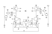
本開示の実施形態によれば、撮像システムが提供される。撮像システムは、光線を放出することができる送信ユニットと、光検出装置を備えるイメージセンサを備える受信ユニットとを備える。 According to embodiments of the present disclosure, an imaging system is provided. The imaging system comprises a transmitting unit capable of emitting light rays and a receiving unit comprising an image sensor comprising a photodetector.
本開示のこれらの目的および他の目的は、様々な図および図面で示されている好ましい実施形態の以下の詳細な記載を読んだ後、当業者には疑いなく明らかとなる。 These and other objects of the present disclosure will no doubt become apparent to those skilled in the art after reading the following detailed description of the preferred embodiments illustrated in the various figures and drawings.
前述の態様、および本出願の付随する利点の多くは、添付の図面と併せて理解されるとき、以下の詳細な記載を参照することでより良く理解されることになるように、より容易に理解されることになる。 The foregoing aspects, and many of the attendant advantages of the present application, will be more readily understood with reference to the following detailed description when read in conjunction with the accompanying drawings. will be understood.
本明細書で使用されているように、「第1の」、「第2の」、「第3の」、「第4の」、および「第5の」などの用語は、様々な要素、構成要素、領域、層、および/または区域を記載しており、これらの要素、構成要素、領域、層、および/または区域はこれらの用語によって限定されるべきではない。これらの用語は、1つの要素、構成要素、領域、層、または区域を他のものから区別するために使用されるだけであり得る。「第1の」、「第2の」、「第3の」、「第4の」、および「第5の」などの用語は、本明細書で使用されるとき、文脈によって明確に指示されていない場合、順序または順番の意味を含んでいない。「光検出」、「光感知」、「光線検出」、「光線感知」といった用語、および任意の他の同様の用語は、相互に置き換え可能に使用できる。 As used herein, terms such as “first,” “second,” “third,” “fourth,” and “fifth” refer to various elements, Components, regions, layers and/or sections are described and these elements, components, regions, layers and/or sections should not be limited by these terms. These terms may only be used to distinguish one element, component, region, layer or section from another. Terms such as "first," "second," "third," "fourth," and "fifth" as used herein are clearly dictated by the context. If not, it does not imply order or order. Terms such as "light detection", "light sensing", "light detection", "light sensing", and any other similar terms may be used interchangeably.
「上方」、「上」、および「下」などの空間的の記載は、他に明示されていない場合、図に示された配向に関連して指示されている。本明細書において使用されている空間的な記載は、図示の目的のためだけであること、および、本明細書に記載されている構造の実用的な実施は、そのような配置によって本開示の実施形態の長所に反しないという前提で任意の配向または様態で空間的に配置できることは、理解されるべきである。 Spatial references such as "above", "above", and "below" are indicated with respect to the orientation shown in the figures unless otherwise indicated. It is intended that the spatial descriptions used herein are for illustration purposes only and that the practical implementation of the structures described herein depends on such arrangements of the present disclosure. It should be understood that they can be spatially arranged in any orientation or manner provided the advantages of the embodiments are not compromised.
本明細書で使用されているように、「真性」という用語は、半導体材料が意図的にドーパントを添加していないことを意味する。 As used herein, the term "intrinsic" means that the semiconductor material is not intentionally doped.
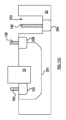
図1Aは、ある実施形態による光検出デバイス100aの断面図を示している。光検出デバイス100aは、吸収領域10と、吸収領域10を支持する基板20とを備える。ある実施形態では、吸収領域10は基板20に全体的に埋め込まれる。ある実施形態では、吸収領域10は基板20に部分的に埋め込まれる。ある実施形態では、光検出デバイス100aは、吸収領域10と、吸収領域10と異なる材料を含む、またはそのような材料から成るキャリア伝導層との間に、少なくとも1つのヘテロ界面を備える。ある実施形態では、キャリア伝導層は基板20である。例えば、ある実施形態では、基板20は、第1の表面21と、第1の表面21と対向する第2の表面22とを備える。ある実施形態では、吸収領域10は、第1の表面11と、第2の表面12と、1つまたは複数の側面13とを備える。第2の表面12は、吸収領域10の第1の表面11と基板20の第2の表面22との間にある。側面13は、吸収領域10の第1の表面11と吸収領域10の第2の表面12との間にある。吸収領域10の第1の表面11、第2の表面12、および側面13のうちの少なくとも1つは、基板20と少なくとも部分的に直接的に接触しており、したがって、ヘテロ界面は吸収領域10と基板20との間に形成される。
FIG. 1A shows a cross-sectional view of a
ある実施形態では、吸収領域10は伝導型でドープされ、第1のピークドーピング濃度を有する第1のドーパントを含む。ある実施形態では、吸収領域10は、例えば入射光線といった光学信号を電気信号へと変換するように構成される。ある実施形態では、光学信号は、基板20の第1の表面21から吸収領域10に入る。ある実施形態では、光学信号は、基板20の第2の表面22から吸収領域10に入る。ある実施形態では、吸収領域10は、光学窓を含む光線遮蔽体(図示されていない)によって定められる吸収の領域ARを備える。吸収の領域ARは、光学窓を通じて入ってくる光学信号を受信する仮想的な領域である。
In one embodiment,
ある実施形態では、ある実施形態では基板20であるキャリア伝導層は、伝導型でドープされ、光検出デバイス100aの暗電流を低減するために第1のピークドーピング濃度より低い第2のピークドーピング濃度を有する第2のドーパントを含み、これは光検出デバイス100aの信号対雑音比、感度、ダイナミックレンジ特性を向上させることができる。
In one embodiment, the carrier conducting layer, which in one embodiment is the
ある実施形態では、第1のピークドーピング濃度は1×1016cm-3以上である。ある実施形態では、第1のピークドーピング濃度は1×1016cm-3と1×1020cm-3との間であり得る。ある実施形態では、第1のピークドーピング濃度は1×1017cm-3と1×1020cm-3との間であり得る。ある実施形態では、第2のピークドーピング濃度に対する第1のピークドーピング濃度の比は、光検出デバイス100aが低暗電流をさらに達成することができるように10以上である。ある実施形態では、第2のピークドーピング濃度に対する第1のピークドーピング濃度の比は、光検出デバイス100aが低暗電流と高量子効率とを同時にさらに達成することができるように100以上である。ある実施形態では、基板20の伝導型はp型またはn型である。ある実施形態では、基板20の伝導型が、例えばホウ素(B)および/またはガリウム(Ga)をドーパントとして用いるp型である場合、第2のピークドーピング濃度は、光検出デバイス100aが低暗電流と高量子効率とを同時に達成することができるように、1×1012cm-3と1×1016cm-3との間であり得る。ある実施形態では、基板20の伝導型が、例えばリン(P)および/またはヒ素(As)をドーパントとして用いるn型のものである場合、第2のピークドーピング濃度は、光検出デバイス100aが低暗電流と高量子効率とを同時に達成することができるように、1×1014cm-3と1×1018cm-3との間であり得る。
In some embodiments, the first peak doping concentration is 1×10 16 cm −3 or greater. In some embodiments, the first peak doping concentration can be between 1×10 16 cm −3 and 1×10 20 cm −3 . In some embodiments, the first peak doping concentration can be between 1×10 17 cm −3 and 1×10 20 cm −3 . In some embodiments, the ratio of the first peak doping concentration to the second peak doping concentration is 10 or more so that the
ある実施形態では、ある実施形態では基板20であるキャリア伝導層の伝導型が、吸収領域10の第1のピークドーピング濃度より低い基板20の第2のピークドーピング濃度を有することで、吸収領域10の伝導型と異なるとき、空乏領域が基板20と吸収領域10との間のヘテロ界面を横切る。光検出デバイスが動作中であるとき、空乏領域の主要な部分は基板20にある。別の言い方をすれば、基板20における空乏領域の第1の幅が吸収領域10における空乏領域の第2の幅より大きい。ある実施形態では、第2の幅に対する第1の幅の比は10より大きい。ある実施形態では、埋め込み電界領域が基板20と吸収領域10との間のヘテロ界面を横切り、暗電流が大部分において基板20から発生させられるように、基板20における埋め込み電界領域の第1の幅が吸収領域10における埋め込み電界領域の第2の幅より大きい。そのため、光検出デバイスはより低い暗電流を達成することができる。ある実施形態では、基板20であるキャリア伝導層のバンドギャップが吸収領域10のバンドギャップより大きい。
In some embodiments, the conductivity type of the carrier conduction layer, which in some embodiments is the
ある実施形態では、吸収領域10の第1のピークドーピング濃度より低い基板20の第2のピークドーピング濃度を有することで、基板20がp型のものであり、吸収領域10がp型のものであるときなど、ある実施形態では基板20であるキャリア伝導層の伝導型が、吸収領域10の伝導型と同じであるとき、吸収領域10を横切る電界を低減させることができ、延いては、基板20を横切る電界を増加させることができる。つまり、吸収領域10を横切る電界と基板20を横切る電界との間の差が存在する。結果として、光検出デバイスの暗電流はさらに低くなる。ある実施形態では、基板20であるキャリア伝導層のバンドギャップが吸収領域10のバンドギャップより大きい。
In some embodiments,
ある実施形態では基板20であるキャリア伝導層は、吸収領域10から分離された第1のドープ領域102を備える。第1のドープ領域102は伝導型でドープされ、第3のピークドーピング濃度を有する第3のドーパントを含む。第1のドープ領域102の伝導型は吸収領域10の伝導型と異なる。ある実施形態では、第3のピークドーピング濃度は第2のピークドーピング濃度より高い。ある実施形態では、第1のドープ領域102の第3のピークドーピング濃度は1×1018cm-3と5×1020cm-3との間であり得る。
A carrier conducting layer, which in some embodiments is the
ある実施形態では、吸収領域10の少なくとも50%が、1×1016cm-3以上の第1のドーパントのドーピング濃度でドープされる。別の言い方をすると、吸収領域10の少なくとも半分が、1×1016cm-3以上のドーピング濃度を有する第1のドーパントで意図的にドープされる。例えば、吸収領域10の厚さに対する吸収領域10におけるドーピング領域の深さの比が1/2以上である。ある実施形態では、吸収領域10の少なくとも80%が、光検出デバイスの暗電流をさらに低減するために、1×1016cm-3以上のドーピング濃度を有する第1のドーパントで意図的にドープされる。例えば、吸収領域10の厚さに対する吸収領域10におけるドーピング領域の深さの比が4/5以上である。
In some embodiments, at least 50% of
ある実施形態では、キャリア伝導層は第2のドーパントでかなりドープされ得る。例えば、ある実施形態では基板20であるキャリア伝導層の少なくとも50%が、1×1012cm-3以上の第2のドーパントのドーピング濃度を有する。別の言い方をすると、キャリア伝導層の少なくとも半分が、1×1012cm-3以上のドーピング濃度を有する第2のドーパントで意図的にドープされる。例えば、基板20の厚さに対する基板20におけるドーピング領域の深さの比が1/2以上である。ある実施形態では、キャリア伝導層の少なくとも80%が、1×1012cm-3以上のドーピング濃度を有する第2のドーパントで意図的にドープされる。例えば、基板20の厚さに対する基板20におけるドーピング領域の深さの比が4/5以上である。
In some embodiments, the carrier conduction layer can be heavily doped with the second dopant. For example, at least 50% of the carrier conducting layer, which in some embodiments is
ある実施形態では、キャリア伝導層はて第2のドーパントで局部的にドープされ得る。例えば、ある実施形態では基板20であるキャリア伝導層は、伝導領域201を含む。伝導領域201の少なくとも一部が第1のドープ領域102と吸収領域10との間にある。ある実施形態では、伝導領域201は、吸収領域10から発生させられて第1のドープ領域102に向けて移動するキャリアの経路を制限するために、吸収領域10および第1のドープ領域102と部分的に重ねられる。ある実施形態では、伝導領域201は、基板20の第1の表面21に対して実質的に垂直な方向D1に沿って基板20の第1の表面21から測定される深さを有する。深さは、第2のドーパントのドーパントプロファイルが1×1014cm-3から1×1015cm-3の間の濃度などの特定の濃度に達する位置までである。ある実施形態では、伝導領域201の深さは、キャリアをより良好に効率的に運搬するために、5μmより小さい。ある実施形態では、伝導領域201は第1のドープ領域102全体と重ねられてもよい。ある実施形態では、伝導領域201は吸収領域10の幅より大きい幅を有する。
In some embodiments, the carrier conduction layer can be locally doped with a second dopant. For example, a carrier conducting layer, which in some embodiments is
ある実施形態では、第1のドーパントと第2のドーパントとは異なり、例えば、第1のドーパントはホウ素であり、第2のドーパントはリンである。ある実施形態では、吸収領域10と、ある実施形態では基板20であるキャリア伝導層との間のヘテロ界面における第1のドーパントのドーピング濃度は、1×1016cm-3以上である。ある実施形態では、ヘテロ界面における第1のドーパントのドーピング濃度は、1×1016cm-3と1×1020cm-3との間、または、1×1017cm-3と1×1020cm-3との間であり得る。ある実施形態では、ヘテロ界面における第2のドーパントのドーピング濃度は、ヘテロ界面における第1のドーパントのドーピング濃度より低い。ある実施形態では、ヘテロ界面における第2のドーパントのドーピング濃度は1×1012cm-3と1×1017cm-3との間である。
In some embodiments, the first dopant and the second dopant are different, eg, the first dopant is boron and the second dopant is phosphorous. In some embodiments, the doping concentration of the first dopant at the heterointerface between the
ある実施形態では、ヘテロ界面における第1のドーパントのドーピング濃度が十分に高いため、ヘテロ界面において発生する境界面の暗電流を低減することができる。結果として、境界面の組み合わせ速度が低減でき、延いては、ヘテロ界面における暗電流がより低くなり得る。ある実施形態では、ヘテロ界面における第2のドーパントのドーピング濃度がヘテロ界面における第1のドーパントのドーピング濃度より低いため、吸収領域10において発生するバルク暗電流も低減される。ある実施形態では、光検出デバイス100aは、104cm/sより低い境界面の再組み合わせ速度を有し得る。
In some embodiments, the doping concentration of the first dopant at the heterointerface is sufficiently high to reduce interface dark current generated at the heterointerface. As a result, the interfacial mating speed can be reduced, which in turn can lead to lower dark currents at the heterointerfaces. In some embodiments, the doping concentration of the second dopant at the heterointerface is lower than the doping concentration of the first dopant at the heterointerface, so that the bulk dark current generated in the absorbing
ある実施形態では、ヘテロ界面における第2のドーパントのドーピング濃度に対する第1のドーパントのドーピング濃度の比は、光検出デバイス100aがヘテロ界面における低暗電流と高量子効率とを同時に達成することができるように10以上である。ある実施形態では、ヘテロ界面における第2のドーパントのドーピング濃度に対する第1のドーパントのドーピング濃度の比は、光検出デバイス100aがヘテロ界面におけるさらなる低暗電流と高量子効率とを同時に示すことができるように100以上である。
In some embodiments, the ratio of the doping concentration of the first dopant to the doping concentration of the second dopant at the heterointerface allows the
ある実施形態では、第2のドーパントは吸収領域10にあり得るが、熱拡散または注入残存などのため、吸収領域10の外側に存在してもよい。ある実施形態では、第1のドーパントは、ある実施形態では基板20であるキャリア伝導層にあり得るが、熱拡散または注入残存などのため、基板領域20の外側に存在してもよい。
In some embodiments, the second dopant may be in the
ある実施形態では、第1のドーパントは、その場成長、イオン注入、および/または熱拡散など、任意の適切な過程によって吸収領域10に導入され得る。
In some embodiments, the first dopant may be introduced into
ある実施形態では、第2のドーパントは、その場成長、イオン注入、および/または熱拡散など、任意の適切な過程によって基板20に導入され得る。
In some embodiments, the second dopant may be introduced into
ある実施形態では、吸収領域10は、第1の材料または第1の材料の複合材料によって作られる。ある実施形態では基板20であるキャリア伝導層は、第2の材料または第2の材料の複合材料によって作られる。第2の材料または第2の材料の複合材料は第1の材料または第1の材料の複合材料と異なる。例えば、ある実施形態では、第2の材料または第2の材料の複合材料の元素の組み合わせが、第1の材料または第1の材料の複合材料における元素の組み合わせと異なる。
In some embodiments,
ある実施形態では、ある実施形態では基板20であるキャリア伝導層のバンドギャップが吸収領域10のバンドギャップより大きい。ある実施形態では、吸収領域10は、半導体材料を含む、または半導体材料から成る。ある実施形態では、基板20は、半導体材料を含む、または半導体材料から成る。ある実施形態では、吸収領域10は、III-V族半導体材料を含む、またはIII-V族半導体材料から成る。ある実施形態では、基板20は、III-V族半導体材料を含む、またはIII-V族半導体材料から成る。III-V族半導体材料は、限定されることはないが、GaAs/AlAs、InP/InGaAs、GaSb/InAs、またはInSbを含み得る。例えば、ある実施形態では、吸収領域10は、InGaAsを含む、またはInGaAsから成り、基板20は、InPを含む、またはInPから成る。ある実施形態では、吸収領域10は、IV族元素を含む半導体材料を含む、または、IV族元素を含む半導体材料から成る。例えば、Ge、Si、またはSnである。ある実施形態では、吸収領域10は、SixGeySn1-x-yを含む、またはSixGeySn1-x-yから成り、ここで、0≦x≦1、0≦y≦1、0≦x+y≦1である。ある実施形態では、吸収領域10は、Ge1-aSnaを含む、またはGe1-aSnaから成り、ここで、0≦a≦0.1である。ある実施形態では、吸収領域10は、GexSi1-xを含む、またはGexSi1-xから成り、ここで、0≦x≦1である。ある実施形態では、真性ゲルマニウムから成る吸収領域10は、吸収領域の形成の間に形成される材料欠陥のため、p型のものであり、ここで、欠陥密度は1×1014cm-3から1×1016cm-3までである。ある実施形態では、ある実施形態では基板20であるキャリア伝導層は、IV族元素を含む半導体材料を含む、または、IV族元素を含む半導体材料から成る。例えば、Ge、Si、またはSnである。ある実施形態では、基板20は、SixGeySn1-x-yを含む、またはSixGeySn1-x-yから成り、ここで、0≦x≦1、0≦y≦1、0≦x+y≦1である。ある実施形態では、基板20は、Ge1-aSnaを含む、またはGe1-aSnaから成り、ここで、0≦a≦0.1である。ある実施形態では、基板20は、GexSi1-xを含む、またはGexSn1-xから成り、ここで、0≦x≦1である。ある実施形態では、真性ゲルマニウムから成る基板20は、吸収領域の形成の間に形成される材料欠陥のため、p型のものであり、ここで、欠陥密度は1×1014cm-3から1×1016cm-3までである。例えば、ある実施形態では、吸収領域10は、Geを含む、またはGeから成り、基板20は、Siを含む、またはSiから成る。
In some embodiments, the bandgap of the carrier conducting layer, which in some embodiments is the
ある実施形態では、吸収領域10の伝導型はp型である。ある実施形態では、第1のドーパントはIII族元素である。ある実施形態では、基板20の伝導型はn型であり、第2のドーパントはV族元素である。
In some embodiments, the conductivity type of
ある実施形態では、光検出デバイスは、第1のドープ領域102に電気的に結合された第1の電極30を備える。第1の電極30は吸収領域10から分離される。抵抗接触が、第1の電極30の材料および第1のドープ領域102の第3のピークドーピング濃度に応じて、第1の電極30と第1のドープ領域102との間に形成され得る。ある実施形態では、第1の電極30と吸収領域の側面13のうちの1つとの間の最短距離dが0.1μmと20μmとの間であり得る。ある実施形態では、第1の電極30と吸収領域の側面13のうちの1つとの間の最短距離dは0.1μmと5μmとの間であり得る。ある実施形態では、距離は0.5μmと3μmとの間であり得る。第1の電極30と側面13との間の距離dが20μmより大きい場合、光検出デバイス100aの速さはより小さくなる。第1の電極30と側面13との間の距離dが0.1μmより小さい場合、光検出デバイスの暗電流を増加させることができる。
In one embodiment, the photodetector device comprises a
ある実施形態では、光検出デバイス100aは、吸収領域10において、吸収領域10の第1の表面11の近くに、第2のドープ領域108を備える。第2のドープ領域108は、吸収領域10の伝導型と同じ伝導型でドープされている。ある実施形態では、第2のドープ領域108は、第1のピークドーピング濃度より高い第4のピークドーピング濃度を有する第4のドーパントを含む。例えば、第2のドープ領域108の第4のピークドーピング濃度は1×1018cm-3と5×1020cm-3との間であり得る。ある実施形態では、第2のドープ領域108は、方向D1に沿って第1のドープ領域102上に配置されない。
In an embodiment, the
ある実施形態では、光検出デバイス100aは、第2のドープ領域108に電気的に結合された第2の電極60をさらに備える。抵抗接触が、第2の電極60の材料および第2のドープ領域108の第4のピークドーピング濃度に応じて、第2の電極60と第2のドープ領域108との間に形成され得る。第2の電極60は、吸収領域10の第1の表面11上にある。
In an embodiment, the
ある実施形態では、キャリア伝導層は、第1の表面と、第1の表面21と対向する第2の表面とを備える。第1の電極30と第2の電極60とは両方ともキャリア伝導層の第1の表面上に配置される。つまり、第1の電極30と第2の電極60とは、ある実施形態では基板20であるキャリア伝導層の同じ側の上に配置され、これは、その後の後部の製作過程にとって有益である。
In one embodiment, the carrier conducting layer comprises a first surface and a second surface opposite the
第1のドープ領域102および第2のドープ領域108は半導体接触領域であり得る。ある実施形態では、第1のドープ領域102および第2のドープ領域108に電気的に結合される回路に応じて、第1のドープ領域102および第2のドープ領域108の一方によって収集される第1の型を伴うキャリアをさらに処理することができ、他方のドープ領域によって収集される第2の型を伴うキャリアを除去することができる。そのため、光検出デバイスは、向上した信頼性と量子効率とを有し得る。
First doped
ある実施形態では、吸収領域10は段階的なドーピングプロファイルでドープされる。ある実施形態では、段階的なドーピングプロファイルの最大濃度は第2のドーパントの第2のピークドーピング濃度より高い。ある実施形態では、段階的なドーピングプロファイルの最小濃度は第2のドーパントの第2のピークドーピング濃度より高い。ある実施形態では、段階的なドーピングプロファイルは、吸収領域10の第1の表面11から、または、第2のドープ領域108から、吸収領域10の第2の表面12へと段階的であり得る。ある実施形態では、段階的なドーピングプロファイルは、キャリアの移動方向に応じて、徐々に減少/増加し得る、または、階段状に減少/増加し得る。ある実施形態では、段階的なドーピングプロファイルの濃度は、キャリアの移動方向に応じて、第1の表面11から、または、吸収領域10の第2のドープ領域108から、吸収領域10の第2の表面12へと徐々に減少/増加させられる。ある実施形態では、段階的なドーピングプロファイルの濃度は、キャリアの移動方向に応じて、吸収領域10の第1の表面11または第2のドープ領域108の中心から、吸収領域10の第2の表面12および側面13へと徐々に径方向へと減少/増加させられる。例えば、吸収領域10が基板20全体にわたる場合、第1のドープ領域102がn型のものであるときに電子などの第1の型を伴うキャリアは、第1の表面11から第2の表面12への方向に実質的に沿って、吸収領域10において移動し、例えばホウ素などの第1のドーパントの段階的なドーピングプロファイルの濃度は、第1の表面11から、または、吸収領域10の第2のドープ領域108から、吸収領域10の第2の表面12へと徐々に減少させられる。ある実施形態では、段階的なドーピングプロファイルの濃度は、キャリアの移動方向に応じて、第1の表面11の縁、または吸収領域10の第2のドープ領域108から、吸収領域10の側面13へと徐々に横方向に減少/増加させられる。
In one embodiment,
ある実施形態では、光検出デバイスの暗電流は、例えば1×10-12A未満といった、約数pA以下である。 In some embodiments, the dark current of the photodetector device is on the order of a few pA or less, eg, less than 1×10 −12 A.
図1Bは、ある実施形態による光検出デバイスの断面図を示している。図1Bにおける光検出デバイス100bは、図1Aにおける光検出デバイス100aと同様である。違いが以下に記載されている。
FIG. 1B shows a cross-sectional view of a photodetector device according to some embodiments.
光検出デバイス100bは、基板20に別の第1のドープ領域104をさらに備える。第1のドープ領域104は、図1Aにおいて記載されているような第1のドープ領域102と同様である。第1のドープ領域104は吸収領域10から分離される。伝導領域201の少なくとも一部が第1のドープ領域104と吸収領域10との間にもある。ある実施形態では、伝導領域201は、吸収領域10から発生させられて第1のドープ領域104に向けて移動する第1の型を伴うキャリアの経路を制限するために、吸収領域10および第1のドープ領域104と部分的に重ねられる。
ある実施形態では、2つの第1のドープ領域104、102は互いから分離されている。ある実施形態では、2つの第1のドープ領域104、102は、例えば輪といった連続した領域であり得る。光検出デバイス100bは、第1のドープ領域104に電気的に結合された第3の電極40をさらに備える。ある実施形態では、第1の電極30および第3の電極40は同じ回路に電気的に結合され得る。
In one embodiment, the two first
ある実施形態では、光検出デバイス100bの暗電流は、例えば1×10-12A未満といった、約数pA以下である。
In some embodiments, the dark current of the
比較例による光検出デバイスが、図1Bにおける光検出デバイス100bの構造と実質的に同じ構造を備える。違いは、比較例の光検出デバイスでは、吸収領域10のドーピング濃度が基板20の第2のピークドーピング濃度以下であり、ヘテロ界面における第2のドーパントのドーピング濃度が、ヘテロ界面における第1のドーパントのドーピング濃度以上であることである。
A photodetector device according to a comparative example has substantially the same structure as the
比較例による光検出デバイス、および光検出デバイス100bの詳細が、表1および表2に列記されている。
Details of the photodetector device according to the comparative example and the


表3を参照すると、比較例と比べて、光検出デバイス100bにおける吸収領域10の第1のピークドーピング濃度が基板20の第2のピークドーピング濃度より高いため、光検出デバイス100bは、例えば少なくとも2倍より低いといった、より低い暗電流を有し得る。
Referring to Table 3, compared to the comparative example, the first peak doping concentration of the absorbing

比較例による別の光検出デバイスが、図1Bにおける光検出デバイス100bの構造と実質的に同じ構造を備える。違いは、比較例の別の光検出デバイスでは、吸収領域10のドーピング濃度が基板20の第2のピークドーピング濃度以下であり、ヘテロ界面における第2のドーパントのドーピング濃度が、ヘテロ界面における第1のドーパントのドーピング濃度以上であることである。比較例による別の光検出デバイス、および光検出デバイス100bの詳細が、表4および表5に列記されている。
Another photodetector device according to a comparative example comprises substantially the same structure as that of


表6を参照すると、別の比較例と比べて、光検出デバイス100bにおける吸収領域10の第1のピークドーピング濃度が基板20の第2のピークドーピング濃度より高いため、光検出デバイス100bは、例えば少なくとも20倍より低いといった、より低い暗電流を有し得る。
Referring to Table 6, compared to another comparative example, the first peak doping concentration of the absorbing

図1Cは、ある実施形態による光検出デバイスの断面図を示している。図1Cにおける光検出デバイス100cは、図1Aにおける光検出デバイス100aと同様である。違いが以下に記載されている。
FIG. 1C shows a cross-sectional view of a photodetector device according to some embodiments. Photodetector device 100c in FIG. 1C is similar to
基板20は、基礎部分20aと、基礎部分20aによって支持された上方部分20bとを備える。上方部分20bは、基礎部分20aの幅より小さい幅を有する。吸収領域10は、基板20の上方部分20bによって支持されている。伝導領域201は上方部分20bにある。第1のドープ領域102は基礎部分20aにある。第1のドープ領域102は基板20の上方部分20bの幅より大きい幅を有し、したがって、第1のドープ領域102の一部は上方部分20bによって覆われていない。第2のドープ領域108は、方向D1に沿って第1のドープ領域102上に配置されており、伝導領域201は第1のドープ領域102と第2のドープ領域108との間にある。例えば電子といった吸収領域10から発生させられた第1の型を伴うキャリアが、方向D1に沿って、伝導領域201を通じて第1のドープ領域102に向けて移動する。
The
ある実施形態では、第1の電極30は、光検出デバイスの上面図からの輪など、任意の適切な形であり得る。ある実施形態では、光検出デバイス100cは、第1のドープ領域102に電気的に結合され、互いから分離された2つの第1の電極30を備える。ある実施形態では、第1の電極30は吸収領域10の反対側に配置される。
In some embodiments, the
ある実施形態では、第2のドープ領域108および第1のドープ領域102に印加される逆方向バイアス電圧に基づいて、衝突イオン化が起こる場合、光検出デバイス100cは、線形モード(逆方向バイアス電圧<降伏電圧)またはガイガーモード(逆方向バイアス電圧>降伏電圧)で動作させられるアバランシェフォトダイオードであり得、吸収領域10と第1のドーピング領域102との間における伝導領域201の一部分は増倍領域であり得る。そのため、増倍領域は、吸収領域10から発生させられる1つまたは複数のキャリアを受信することに応答して、1つまたは複数の追加の電荷キャリアを発生させることができる。
In an embodiment, the photodetector device 100c operates in a linear mode (reverse bias voltage < breakdown voltage) or an avalanche photodiode operated in Geiger mode (reverse bias voltage>breakdown voltage), the part of the conducting
図1Dは、ある実施形態による光検出デバイスの断面図を示している。図1Dにおける光検出デバイス100dは、図1Cにおける光検出デバイス100cと同様である。違いが以下に記載されている。
FIG. 1D shows a cross-sectional view of a photodetector device according to some embodiments.
光検出デバイス100dは、基板20の上方部分20bにおいて電荷層202をさらに備える。電荷層202は、吸収領域10と直接的に接触している、または、吸収領域10の一部分と重ねられている。電荷層202は、吸収領域10の伝導型と同じ伝導型のものである。例えば、吸収領域10の伝導型がpである場合、電荷層202の伝導型はpである。電荷層202が、伝導領域201の第2のピークドーピング濃度より高く、吸収領域10の第1のピークドーピング濃度より低いピークドーピング濃度を伴う。ある実施形態では、電荷層202は10nmから500nmの間の厚さを伴う。電荷層は、吸収領域10を横切る電界を低減することができ、それによって、伝導領域201を横切る電界を増加させることができる。つまり、吸収領域10を横切る電界と伝導領域201を横切る電界との間の差が存在する。結果として、光検出デバイス100dの速さおよび反応性もより高くなり、光検出デバイス100dの暗電流もより小さくなる。
図2Aは、ある実施形態による光検出デバイスの断面図を示している。図2Aにおける光検出デバイス200aは、図1Aにおける光検出デバイス100aと同様である。違いが以下に記載されている。第2のドープ領域108が基板20にある。別の言い方をすると、第2のドープ領域108の第4のピークドーピング濃度が基板20に位置する。ある実施形態では、第2のドープ領域108は、基板20の第1の表面21の下方にあり、吸収領域10と直接的に接触しており、例えば、第2のドープ領域108は、吸収領域10の側面13のうちの1つと接触してもよく、または、側面13のうちの1つと重ねられてもよい。結果として、吸収領域10から発生させられるキャリアは、吸収領域10から、吸収領域10と基板20との間のヘテロ界面を通じて、第2のドープ領域108に向けて移動することができる。第2の電極60は、基板20の第1の表面21上にある。
FIG. 2A shows a cross-sectional view of a photodetector device according to an embodiment.
吸収領域10の代わりに基板20に第2のドープ領域108を有することで、第2の電極60と第1の電極30とは両方とも基板20の第1の表面21の上方に形成され得る。そのため、第2の電極60と第1の電極30との間の高さの差を縮小することができ、それによって、その後の製作過程がこの設計から恩恵を受けることになる。他にも、光学信号を吸収する吸収領域10の面積をより大きくすることができる。
By having second doped
図2Bは、ある実施形態による光検出デバイスの断面図を示している。図2Bにおける光検出デバイス200bは、図2Aにおける光検出デバイス200aと同様である。違いが以下に記載されている。第2のドープ領域108は、吸収領域10の第2の表面12とも接触し得る、または、第2の表面12とも重ねられ得る。
FIG. 2B shows a cross-sectional view of a photodetector device according to some embodiments.
図2Cは、ある実施形態による光検出デバイスの断面図を示している。図2Cにおける光検出デバイス200cは、図2Bにおける光検出デバイス200bと同様である。違いが以下に記載されている。吸収領域10は基板20全体にわたる。第2のドープ領域108の一部が吸収領域10によって覆われる。ある実施形態では、吸収領域10によって覆われる第2のドープ領域108の幅w2が0.2μmより大きくなり得る。ある実施形態では、吸収領域10は幅w1を有する。幅w2は0.5w1以下である。この設計によって、2つの異なる型のキャリアが、吸収領域10から第1のドープ領域102へと、および、吸収領域10から第2のドープ領域108へと、障害なくそれぞれ移動することができる。
FIG. 2C shows a cross-sectional view of a photodetector device according to some embodiments.
図2Dは、ある実施形態による光検出デバイスの断面図を示している。図2Dにおける光検出デバイス200dは、図2Aにおける光検出デバイス200aと同様である。違いが以下に記載されている。吸収領域10は基板20に全体的に埋め込まれている。ある実施形態では、第1のドーパントの段階的なドーピングプロファイルは、第2のドープ領域108の近くの側面13から、伝導領域201の近くの側面13へと徐々に横方向に減少させられる。図2Eは、ある実施形態による光検出装置の概略図を示している。光検出装置200eは、ピクセル(符号付けされていない)と、ピクセルに電気的に結合されるカラムバスとを備える。ピクセルは、光検出デバイスと、光検出デバイスおよびカラムバスに電気的に結合される読み取り回路(符号付けされていない)とを備える。光検出デバイスは、例えば図1Aにおける光検出デバイス100aといった、図1A~図1Dおよび図2A~図2Dにおけるいずれかの光検出デバイスであり得る。ある実施形態では、読み取り回路(符号付けされていない)とカラムバスとは、他の基板に製作されてもよく、ダイ/ウェーハ接合または積み重ねを介して光検出デバイスと一体化/一括実装されてもよい。ある実施形態では、光検出装置200eは、読み取り回路と光検出デバイスとの間に接合層(図示されていない)を備える。接合層は、酸化物、半導体、金属、または合金など、任意の適切な材料を含み得る。
FIG. 2D shows a cross-sectional view of a photodetector device according to some embodiments.
ある実施形態では、読み取り回路は、第1の型を伴う収集されたキャリアを処理するために、第1のドープ領域102または第2のドープ領域108に電気的に結合され得、また、供給電圧または接地電圧が、第1の型と反対の第2の型を伴う他方のキャリアを除去するために、他方のドープ領域に印加され得る。
In an embodiment, a read circuit may be electrically coupled to the first
例えば、第1のドープ領域102がn型のものであり、第2のドープ領域108がp型のものである場合、読み取り回路は、さらなる適用に向けて収集された電子を処理するために、第1のドープ領域102に電気的に結合でき、接地電圧が、正孔を除去するために第2のドープ領域108に印加され得る。他の例について、読み取り回路は、さらなる処理に向けて収集された正孔を処理するために、第2のドープ領域108に電気的に結合されてもよく、供給電圧が、電子を除去するために第1のドープ領域102に印加されてもよい。
For example, if the first
ある実施形態では、読み取り回路は、リセットゲート、ソースフォロワ、および選択ゲートから成る3つのトランジスタ構成、追加の転送ゲートを含む4つのトランジスタ構成、または、収集された電荷を処理するための任意の適切な回路であり得る。例えば、読み取り回路は、転送トランジスタ171Aと、リセットトランジスタ141Aと、リセットトランジスタ141Aに結合されたコンデンサ150Aと、ソースフォロワ142Aと、行選択トランジスタ143Aとを備える。コンデンサ150Aの例は、限定されることはないが、浮遊拡散コンデンサ、金属-酸化物-金属(MOM)コンデンサ、金属-絶縁体-金属(MIM)コンデンサ、および金属-酸化物-半導体(MOS)コンデンサを含む。
In some embodiments, the read circuit is a three transistor configuration consisting of a reset gate, a source follower, and a select gate, a four transistor configuration including an additional transfer gate, or any other suitable configuration for handling the collected charge. circuit. For example, read circuitry includes
転送トランジスタ171Aは、キャリアを光検出デバイス100aからコンデンサ150Aへと転送する。別の言い方をすれば、転送トランジスタ171Aは、切替信号TG1に応じて光電流IA1を出力するように構成されている。切替信号TG1が転送トランジスタ171Aをオンするとき、光電流IA1が発生させられる。
開始において、リセット信号RSTは、VDDへの出力電圧VOUT1をリセットする。次に、切替信号TG1が転送トランジスタ171Aをオンするとき、光電流IA1が発生させられ、コンデンサ150Aにおける出力電圧VOUT1は、切替信号TG1がトランジスタ171Aをオフにするまで低下する。
At the start, the reset signal RST resets the output voltage VOUT1 to VDD. Then, when switching signal TG1 turns on
別のある実施形態では、読み取り回路は、他の基板に製作されてもよく、ダイ/ウェーハ接合または積み重ねを介して光検出デバイス100aと一体化/一括実装されてもよい。
In certain other embodiments, the readout circuitry may be fabricated on other substrates and integrated/packaged with the
ある実施形態では、光検出装置は、1秒間あたり1000フレーム(1000fps)以下のフレームレートで動作させられるCMOSイメージセンサである。 In some embodiments, the photodetector is a CMOS image sensor operated at a frame rate of 1000 frames per second (1000 fps) or less.
図2Fは、ある実施形態による光検出装置の回路の概略図を示している。光検出装置200fは、図2Eにおける光検出装置200eと同様である。違いが以下に記載されている。
FIG. 2F shows a schematic diagram of a circuit of a photodetector according to an embodiment. Photodetector 200f is similar to
光検出装置200fの読み取り回路は、転送トランジスタ171Aとコンデンサ150Aとの間に電圧制御トランジスタ130Aをさらに備える。電圧制御トランジスタ130Aは電流バッファとして構成される。明確には、電圧制御トランジスタ130Aの出力端子がコンデンサ150Aの入力端子に結合され、電圧制御トランジスタ130Aの入力端子がトランジスタ171Aの出力端子に結合される。電圧制御トランジスタ130Aの制御端子は制御電圧VC1に結合される。
The read circuit of photodetector 200f further comprises a
電圧制御トランジスタ130Aが転送トランジスタ171Aとコンデンサ150Aとの間に結合されるため、転送トランジスタ171Aの出力端子とコンデンサ150Aの入力端子とは分離されている。電圧制御トランジスタ130Aが閾値下または飽和領域で動作させられるとき、転送トランジスタ171Aの出力端子は、光検出デバイス100aによって発生させられる暗電流を低減するために、定電圧VA1において制御されまたはこの出力端子にバイアスがかけられ得る。
Since
図3Aは、ある実施形態による光検出デバイスの上面図を示している。図3Bは、ある実施形態による図3AにおけるA-A’の線に沿っての断面図を示している。光検出デバイスは、吸収領域10と、吸収領域10を支持する基板20とを備える。吸収領域10は、図1Aにおいて記載されているような吸収領域10と同様である。基板20は、図1Aにおいて記載されているような基板20と同様である。図3Aにおける光検出デバイス300aと図1Aにおける光検出デバイス100aとの間の違いは、以下に記載されている。光検出デバイス300aは、吸収領域10に電気的に結合されており、ある実施形態では基板20であるキャリア伝導層に部分的に形成されている第1のスイッチ(符号付けされていない)および第2のスイッチ(符号付けされていない)を備える。第1のスイッチは、制御電極340aを備える制御領域C1を備える。第1のスイッチは、制御電極340aから分離された読み出し電極330aをさらに備える。第2のスイッチは、制御電極340bを備える制御領域C2を備える。第2のスイッチは、制御電極340bから分離された読み出し電極330bをさらに備える。ある実施形態では、読み出し電極330a、330bおよび制御電極340a、340bは、基板20の第1の表面21上に形成され、吸収領域10から分離される。ある実施形態では、読み出し電極330aと読み出し電極330bとは、吸収領域10の反対側に配置される。ある実施形態では、制御電極の一方と吸収領域の1つまたは複数の側面との間の最短距離が0.1μmと20μmとの間である。
FIG. 3A shows a top view of a photodetector device according to some embodiments. FIG. 3B shows a cross-sectional view along line A-A' in FIG. 3A according to an embodiment. The photodetector device comprises an absorbing
ある実施形態では、光検出装置は、前述されているような光検出デバイス300aを備えるピクセルを備え、ピクセルは、例えば第1の制御信号および第2の制御信号といった2つの制御信号をさらに含み、それらの制御信号は、吸収領域10における吸収した光子によって発生させられる電子または正孔の移動方向を制御するために、制御領域C1、C2をそれぞれ制御する。ある実施形態では、第1の制御信号は第2の制御信号と異なる。例えば、電圧が使用されるとき、制御信号のうちの一方に、他方の制御信号に対してバイアスがかけられる場合、電界が、吸収領域10におけるのと同様に制御電極340a、340bのすぐ下の2つの部分の間において作り出され、吸収領域10における自由キャリアが、電界の方向に応じて、読み出し電極330b、330aのすぐ下の部分のうちの一方に向けてドリフトする。ある実施形態では、第1の制御信号は第1の位相を含み、第2の制御信号は第2の位相を含み、ここで、第1の制御位相は第2の制御位相と重ねられない。ある実施形態では、第1の制御信号は電圧値Vで固定され、第2の制御信号は電圧値V±ΔVの間で行き来する。ある実施形態では、ΔVは、例えば0Vと3Vとの間で動作させられる正弦波信号、クロック信号、またはパルス信号といった、変化する電圧信号によって発生させられる。バイアス値の方向が、吸収領域10から発生させられるキャリアのドリフト方向を決定する。制御信号は変調信号である。
In an embodiment, the photodetector arrangement comprises a pixel comprising a
ある実施形態では、第1のスイッチは読み出し電極330aの下に第1のドープ領域302aを備える。第2のスイッチは読み出し電極330bの下に第1のドープ領域302bを備える。ある実施形態では、第1のドープ領域302a、302bは、吸収領域10の伝導型と異なる伝導型のものである。ある実施形態では、第1のドープ領域302a、302bは、ドーパントと、ピークドーパント濃度を伴うドーパントプロファイルとを含む。ある実施形態では、第1のドープ領域302a、302bのピークドーピング濃度は第2のピークドーピング濃度より高い。ある実施形態では、第1のドープ領域302a、302bのピークドーパント濃度は、読み出し電極330a、330bの材料と基板20の材料とに依存し、例えば、5×1018cm-3と5×1020cm-3との間であり得る。第1のドープ領域302a、302bは、2つの制御信号の制御に基づいて、吸収領域10から発生させられる第1の型を伴うキャリアを収集するためのキャリア収集領域である。
In one embodiment, the first switch comprises a first
ある実施形態では、キャリアの復調およびキャリアの収集など、吸収機能およびキャリア制御機能は、吸収領域10と、ある実施形態では基板20であるキャリア伝導層とでそれぞれ動作する。
In some embodiments, absorption and carrier control functions, such as carrier demodulation and carrier collection, operate in the
ある実施形態では、光検出デバイス300aは、図1Aにおける第2のドープ領域108および第2の電極60とそれぞれ同様である第2のドープ領域108および第2の電極60を備え得る。第2のドープ領域108は、光検出デバイスの動作の間に第1のドープ領域302a、302bによって収集されない、第1の型と反対の第2の型のキャリアを除去するためのものである。ある実施形態では、制御電極340aは、第2の電極60を通過する軸に関して、制御電極340bと対称である。ある実施形態では、読み出し電極330aは、第2の電極60を通過する軸に関して、読み出し電極330bと対称である。制御電極340a、340b、読み出し電極330a、330b、および第2の電極60は、すべてキャリア伝導層の第1の表面上に配置される。つまり、制御電極340a、340b、読み出し電極330a、330b、および第2の電極60は、ある実施形態では基板20であるキャリア伝導層の同じ側の上にある。
In some embodiments,
ある実施形態では、光検出デバイス300aの基板20は、図1Aに記載されているような伝導領域201と同様の伝導領域201を備える。違いが以下に記載されている。ある実施形態では、光検出デバイス300aの断面図から、伝導領域201の幅が、2つの読み出し電極330a、330bの間の距離より大きくなり得る。ある実施形態では、伝導領域201は第1のドープ領域302a、302b全体と重ねられる。ある実施形態では、伝導領域201の幅は、2つの読み出し電極330a、330bの間の距離より小さくでき、2つの制御電極340a、340bの間の距離より大きくできる。ある実施形態では、伝導領域201は、第1のドープ領域302aの一部分および第1のドープ領域302bの一部分と重ねられる。伝導領域201が第1のドープ領域302aの一部分および第1のドープ領域302bの一部分と重ねられるため、吸収領域10から発生させられる第1の型を伴うキャリアは、伝導領域201に制限させることができ、2つの制御信号の制御に基づいて、第1のドープ領域302a、302bの一方に向けて移動することができる。例えば、第1のドープ領域302a、302bがn型のものである場合、伝導領域201はn型のものであり、第2のドープ領域108はp型であり、吸収領域10から発生させられる電子は、伝導領域201において制限され、2つの制御信号の制御に基づいて、第1のドープ領域302a、302bの一方に向けて移動することができ、正孔は、第2のドープ領域108に向けて移動することができ、回路によってさらに除去され得る。
In some embodiments, the
ある実施形態では、光検出装置は、複数の繰り返しのピクセルを含むピクセル配列を備える。ある実施形態では、ピクセル配列は、ピクセルの一次元または二次元の配列であり得る。 In some embodiments, the photodetector device comprises a pixel array comprising a plurality of repeating pixels. In some embodiments, a pixel array can be a one-dimensional or two-dimensional array of pixels.
比較例による光検出デバイスが、図3Aにおける光検出デバイス300aの構造と実質的に同じ構造を備え、違いは、比較例の光検出デバイスでは、吸収領域10のドーピング濃度が基板20の第2のピークドーピング濃度以下であり、ヘテロ界面における第2のドーパントのドーピング濃度が、ヘテロ界面における第1のドーパントのドーピング濃度以上であることである。
A photodetector device according to the comparative example comprises substantially the same structure as the structure of the
比較例による光検出デバイス、および光検出デバイス300aの詳細が、表7および表8に列記されている。
Details of the photodetector device according to the comparative example and the


表9および表10を参照すると、比較例と比べて、光検出デバイス300aにおける吸収領域10の第1のピークドーピング濃度が基板20の第2のピークドーピング濃度より高いため、光検出デバイス300aは、例えば少なくとも100倍より低いといった、より低い暗電流を有し得る。
Referring to Tables 9 and 10, compared to the comparative example, the first peak doping concentration of the absorbing


ある実施形態では、電圧が第2の電極60に印加され得る。ある実施形態では、第2の電極60に印加される電圧は、第2のドープ領域108と制御領域C1、C2との間の漏れ電流を低下させることができる。ある実施形態では、電圧は、光検出デバイス300aを動作させるときの制御電極340aに印加される電圧と制御電極340bに印加される電圧との間である。
In some embodiments, a voltage may be applied to
図4Aは、ある実施形態による光検出デバイスの上面図を示している。図4Bは、ある実施形態による図4AにおけるA-A’の線に沿っての断面図を示している。図4Cは、ある実施形態による図4AにおけるB-B’の線に沿っての断面図を示している。図4Aにおける光検出デバイス400aは、図3Aにおける光検出デバイス300aと同様である。違いが以下に記載されている。
FIG. 4A shows a top view of a photodetector device according to some embodiments. FIG. 4B shows a cross-sectional view along line A-A' in FIG. 4A according to an embodiment. FIG. 4C shows a cross-sectional view along line B-B' in FIG. 4A according to some embodiments.
図4Aおよび図4Bを参照すると、第2のドープ領域108が基板20にある。別の言い方をすると、第2のドープ領域108の第4のピークドーピング濃度が基板20に位置する。第2のドープ領域108は、基板20の第1の表面21の下方にあり、吸収領域10と直接的に接触しており、例えば、第2のドープ領域108は、吸収領域10の側面13のうちの1つと接触してもよく、または、側面13のうちの1つと重ねられてもよい。結果として、第1のドープ領域302a、302bによって収集されない第2の型を伴うキャリアは、吸収領域10から、吸収領域10と基板20との間のヘテロ界面を通じて、第2のドープ領域108に向けて移動することができる。
Referring to FIGS. 4A and 4B, a second
例えば、第1のドープ領域302a、302bがn型のものである場合、伝導領域201はn型のものであり、第2のドープ領域108はp型であり、吸収領域10から発生させられる電子は、伝導領域201において制限され、2つの制御信号の制御に基づいて、第1のドープ領域302a、302bの一方に向けて移動することができ、正孔は、吸収領域10と基板20との間のヘテロ界面を通じて第2のドープ領域108に向けて移動することができ、回路によってさらに除去され得る。
For example, if the first
第2の電極60は、基板20の第1の表面21上にある。吸収領域10の代わりに基板20に第2のドープ領域108を有することで、第2の電極60、読み出し電極330a、330b、および制御電極340a、340bはすべて基板20の第1の表面21の上方において同一平面上に形成され得る。そのため、第2の電極60および4つ電極330a、330b、340a、340bのうちの任意の2つの間の高さの差を縮小することができ、それによって、その後の製作過程がこの設計から恩恵を受けることになる。他にも、光学信号を吸収する吸収領域10の面積をより大きくすることができる。
A
図5Aは、ある実施形態による光検出デバイスの上面図を示している。図5Bは、ある実施形態による図5AにおけるA-A’の線に沿っての断面図を示している。図5Cは、ある実施形態による図5AにおけるB-B’の線に沿っての断面図を示している。図4Aにおける光検出デバイス500aは、図4Aにおける光検出デバイス400aと同様である。違いが以下に記載されている。読み出し電極330a、330bおよび制御電極340a、340bは吸収領域10の同じ側に配置され、これは、キャリアが吸収領域10から側面13のうちの1つを通じて外に移動させられるため、光検出デバイス400aのコントラスト比を向上させる。ある実施形態では、方向Yに沿っての読み出し電極330a、330bの間の距離は、方向Yに沿っての制御電極340a、340bの間の距離より大きくできる。ある実施形態では、方向Yに沿っての読み出し電極330a、330bの間の距離は、方向Yに沿っての制御電極340a、340bの間の距離と実質的に同じであり得る。
FIG. 5A shows a top view of a photodetector device according to an embodiment. FIG. 5B shows a cross-sectional view along line A-A' in FIG. 5A according to an embodiment. FIG. 5C shows a cross-sectional view along line B-B' in FIG. 5A according to some embodiments.
図6Aは、ある実施形態による光検出デバイスの上面図を示している。図6Bは、ある実施形態による図6AにおけるA-A’の線に沿っての断面図を示している。図6Aにおける光検出デバイス600aは、図5Aにおける光検出デバイス500aと同様であり、例えば、読み出し電極330a、330bおよび制御電極340a、340bは吸収領域10の同じ側に配置されている。違いが以下に記載されている。
FIG. 6A shows a top view of a photodetector device according to some embodiments. FIG. 6B shows a cross-sectional view along line A-A' in FIG. 6A according to some embodiments. The
図6Aおよび図6Bを参照すると、第2のドープ領域108が基板20にある。別の言い方をすると、第2のドープ領域108の第4のピークドーピング濃度が基板20に位置する。第2のドープ領域108は、基板20の第1の表面21の下方にあり、吸収領域10と直接的に接触しており、例えば、第2のドープ領域108は、吸収領域10の側面13のうちの1つと接触してもよく、または、側面13のうちの1つと重ねられてもよい。結果として、第1のドープ領域302a、302bによって収集されない第2の型を伴うキャリアは、吸収領域10から、吸収領域10と基板20との間のヘテロ界面を通じて、第2のドープ領域108に向けて移動することができる。第2の電極60は、基板20の第1の表面21上にある。吸収領域10は、第2の電極60と電極330a、330b、340a、340bとの間にある。
Referring to FIGS. 6A and 6B, a second
吸収領域10の代わりに基板20に第2のドープ領域108を有することで、第2の電極60および4つの電極330a、330b、340a、340bはすべて基板20の第1の表面21の上方において同一平面上に形成され得る。そのため、第2の電極60および4つ電極330a、330b、340a、340bのうちの任意の2つの間の高さの差を縮小することができ、それによって、その後の製作過程がこの設計から恩恵を受けることになる。他にも、光学信号を吸収する吸収領域10の面積をより大きくすることができる。
By having the second
ある実施形態では、伝導領域201は第1のドープ領域302a、302b全体と重ねられ得る。
In some embodiments, the
図6Cは、ある実施形態による光検出デバイスの上面図を示している。図6Dは、ある実施形態による図6CにおけるA-A’の線に沿っての断面図を示している。図6Eは、ある実施形態による図6CにおけるB-B’の線に沿っての断面図を示している。図6Cにおける光検出デバイス600cは、図6Aにおける光検出デバイス600aと同様であり、違いが以下に記載されている。光検出デバイス600cは、吸収領域10と基板20との間のヘテロ界面の少なくとも一部を覆うために、吸収領域10と第1のドープ領域302a、302bとの間に制限領域180をさらに備える。制限領域180は、第1のドープ領域302a、302bの伝導型と異なる伝導型を有する。ある実施形態では、制限領域180は、ピークドーピング濃度を有するドーパントを含む。ピークドーピング濃度は1×1016cm-3以上である。伝導領域201は、光キャリアを吸収領域10から第1のドープ領域302a、302bに向けて移動させるために、伝導領域201の一部を吸収領域10と直接的に接触させたままにするように、制限領域180を通じて形成される通路181を有する。つまり、通路181は制限領域180によって覆われていない。ある実施形態では、制限領域180のピークドーピング濃度は伝導領域201の第2のピークドーピング濃度より低い。ある実施形態では、制限領域180のピークドーピング濃度は伝導領域201の第2のピークドーピング濃度より高い。例えば、光検出デバイスが電子を収集するように構成されるとき、制限領域180はp型のものであり、第1のドープ領域302a、302bはn型のものである。光キャリアが吸収領域10から発生させられた後、正孔は第2のドープ領域108および第2の電極60を通じて除去され、電子は、制限領域180によって制限され、吸収領域10と基板20との間のヘテロ界面全体から外へ移動する代わりに、吸収領域10から通路181を通じて第1のドープ領域302a、302bの一方に向けて移動する。したがって、光検出デバイス600cは、吸収領域10と第1のドープ領域302a、302bとの間に制限領域180を含めることで、向上した復調コントラストを有し得る。
FIG. 6C shows a top view of a photodetector device according to some embodiments. FIG. 6D shows a cross-sectional view along line AA′ in FIG. 6C according to some embodiments. FIG. 6E shows a cross-sectional view along line BB' in FIG. 6C according to some embodiments.
図6Fは、ある実施形態による光検出デバイスの上面図を示している。図6Fにおける光検出デバイス600fは、図6Cにおける光検出デバイス600cと同様である。違いは、吸収領域10の他の側面13から外へ移動する代わりに、キャリアをさらに制限して吸収領域10の側面13のうちの1つにおいて通路181を通過させるために、制限領域180が吸収領域10の2つの他の側面13を覆うように延長させられていることである。ある実施形態では、制限領域180のピークドーピング濃度は第2のドープ領域108のピークドーピング濃度より低い。ある実施形態では、制限領域180および第2のドープ領域108は、異なるマスクを使用することなど、2つの異なる製作処理ステップによって形成される。
FIG. 6F shows a top view of a photodetector device according to some embodiments.
図6Gは、ある実施形態による光検出デバイスの上面図を示している。図6Gにおける光検出デバイス600gは、図6Fにおける光検出デバイス600fと同様である。違いは、第2のドープ領域108が図6Fに記載されている制限領域180として機能できることである。別の言い方をすれば、第2のドープ領域108は、第1のドープ領域302a、302bによって収集されないキャリアを除去することと、吸収領域10から収集されるキャリアを、吸収領域10の他の側面13から外へ移動させる代わりに、側面13のうちの1つにおいて通路181を通じて第1のドープ領域302a、302bの一方に向けて制限することとの両方が可能である。
FIG. 6G shows a top view of a photodetector device according to an embodiment. Photodetector device 600g in FIG. 6G is similar to
図7Aは、ある実施形態による光検出デバイスの上面図を示している。図7Bは、ある実施形態による図7AにおけるA-A’の線に沿っての断面図を示している。光検出デバイス700aは、図3Aにおける光検出デバイス300aと同様である。違いが以下に記載されている。ある実施形態では、光検出デバイスは、吸収領域10に電気的に結合され、基板20に部分的に形成されるN個のスイッチを備え、ここで、Nは3より大きい整数である。例えば、Nは3、4、5などであり得る。ある実施形態では、光検出装置のピクセルは、互いと異なるY個の制御信号をさらに含み、ここで、3≦Y≦Nであり、Yは正の整数であり、制御信号の各々は、光検出デバイス700aの制御領域のうちの1つまたは複数を制御する。ある実施形態では、制御信号の各々は位相を含み、制御信号のうちの1つの位相は、制御信号のうちの他の制御信号の位相と重ねられない。図7Aおよび図7Bを参照すると、ある実施形態では、光検出デバイス700aは、吸収領域10に電気的に結合され、基板20に部分的に形成される4個のスイッチ(符号付けされていない)を備える。スイッチの各々は、制御電極340a、340b、340c、340dを備える制御領域C1、C2、C3、C4を備える。スイッチの各々は、制御電極340a、340b、340c、340dから分離された読み出し電極330a、330b、330c、330dを備える。ある実施形態では、読み出し電極330a、330b、330c、330dおよび制御電極340a、340b、340c、340dは、基板20の第1の表面21上に形成され、吸収領域10から分離される。
FIG. 7A shows a top view of a photodetector device according to some embodiments. FIG. 7B shows a cross-sectional view along line A-A' in FIG. 7A according to an embodiment.
ある実施形態では、4個のスイッチは4つの側面13にそれぞれ配置される。
In one embodiment, four switches are arranged on each of the four
ある実施形態では、スイッチの各々は、読み出し電極330a、330b、330c、330dの下に第1のドープ領域(図示されていない)を含み、第1のドープ領域は、図3Aに記載されているような第1のドープ領域302a、302bと同様である。
In one embodiment, each of the switches includes a first doped region (not shown) under
ある実施形態では、光検出装置のピクセルは、吸収領域10によって発生させられる電子または正孔の移動方向を制御するように、制御領域C1、C2、C3、C4をそれぞれ制御するための4つの制御信号を含む。例えば、電圧が使用されるとき、制御領域C1を制御する制御信号に、他の制御信号に対してバイアスがかけられる場合、電界が、吸収領域10におけるのと同様に制御電極340a、340b、340c、340dのすぐ下の4つの部分の間において作り出され、吸収領域10における自由キャリアが、電界の方向に応じて、読み出し電極330a、330b、330c、330dの下の第1のドープ領域のうちの1つに向けてドリフトする。ある実施形態では、制御信号の各々が、互いの位相によって重ねられない位相を有する。
In one embodiment, the photodetector pixel has four controls for controlling the control regions C1, C2, C3, C4, respectively, so as to control the direction of movement of electrons or holes generated by the absorbing
ある実施形態では、伝導領域201は、長方形または正方形など、任意の適切な形であり得る。
In some embodiments,
図7Cは、ある実施形態による光検出デバイスの上面図を示している。光検出デバイス700cは、図7Aにおける光検出デバイス700aと同様である。違いが以下に記載されている。読み出し電極330a、330b、330c、330dの配置と制御電極340a、340b、340c、340dの配置とは異なる。例えば、4個のスイッチが吸収領域10の4つの角にそれぞれ配置される。
FIG. 7C shows a top view of a photodetector device according to some embodiments.
図7Dは、ある実施形態による光検出デバイスの上面図を示している。光検出デバイス700dは、図7Aにおける光検出デバイス700aと同様である。違いが以下に記載されている。光検出デバイス700dは、吸収領域10に電気的に結合され、基板20に部分的に形成される8個のスイッチ(符号付けされていない)を備える。同様に、スイッチの各々は、制御電極340a、340b、340c、340d、340e、340f、340g、340hを含む制御領域(符号付けされていない)を備え、制御電極340a、340b、340c、340d、340e、340f、340g、340hから分離された読み出し電極330a、330b、330c、330d、330e、330f、330g、330hを備える。
FIG. 7D shows a top view of a photodetector device according to some embodiments.
ある実施形態では、光検出装置は、前述されているような光検出デバイス700dを備えるピクセルを備え、ピクセルは、互いと異なり、光検出デバイス700dの多重スイッチを制御する複数の制御信号を含む。つまり、同じピクセルにおいて、制御信号の数はスイッチの数より小さい。例えば、ピクセルは、互いと異なる2つの制御信号を含むことができ、制御信号の各々はスイッチのうちの2つを制御する。例えば、制御電極340aと制御電極340bとは、同じ制御信号に電気的に結合され、同じ制御信号によって制御され得る。ある実施形態では、ピクセルは、それぞれのスイッチを制御する複数の制御信号を含み得る。つまり、同じピクセルにおいて、制御信号の数はスイッチの数と等しい。例えば、光検出装置のピクセルは、互いと異なり、光検出デバイス700dのそれぞれのスイッチを制御する8つの制御信号を含む。
In one embodiment, the photodetector arrangement comprises a pixel comprising a
図7Eは、ある実施形態による光検出デバイスの上面図を示している。光検出デバイス700eは、図7Dにおける光検出デバイス700dと同様である。違いが以下に記載されている。読み出し電極330a、330b、330c、330d、330e、330f、330g、330hの配置と制御電極340a、340b、340c、340d、340e、340f、340g、340hの配置とは異なる。例えば、8個のスイッチのうちの1つおきのスイッチが吸収領域10の4つの角にそれぞれ配置される。伝導領域201は、限定されることはないが、八角形であり得る。
FIG. 7E shows a top view of a photodetector device according to some embodiments.
図8Aは、ある実施形態による光検出デバイスの上面図を示している。図8Bは、ある実施形態による図8AにおけるA-A’の線に沿っての断面図を示している。図8Aにおける光検出デバイス800aは、図7Aにおける光検出デバイス700aと同様である。違いが以下に記載されている。第2のドープ領域108が基板20にある。別の言い方をすると、第2のドープ領域108の第4のピークドーピング濃度が基板20に位置する。ある実施形態では、第2のドープ領域108は、互いから分離され、吸収領域10と直接的に接触している複数の小領域108a、108b、108c、108dを備え、例えば、小領域108a、108b、108c、108dは、吸収領域10の側面13の少なくとも一部と接触し得る、または重ねられ得る。結果として、吸収領域10から発生させられ、第1のドープ領域によって収集されないキャリアは、吸収領域10から、吸収領域10と基板20との間のヘテロ界面を通じて、小領域108a、108b、108c、108dのうちの1つまたは複数に向けて移動することができる。ある実施形態では、収集されるキャリアの経路が吸収領域10から第1のドープ領域のうちの1つに向けて移動するのを妨げるのを回避するために、小領域108a、108b、108c、108dが吸収領域10と任意のスイッチの第1のドープ領域との間にない。例えば、ある実施形態では、吸収領域10から小領域108a、108b、108c、108dのうちの1つまたは複数に向けて移動する正孔の経路と、吸収領域10から第1のドープ領域のうちの1つに向けて移動する電子の経路とが異なるように、小領域108a、108b、108c、108dは吸収領域10の4つの角にそれぞれ配置され、4個のスイッチは4つの側面13にそれぞれ配置される。
FIG. 8A shows a top view of a photodetector device according to an embodiment. FIG. 8B shows a cross-sectional view along line A-A' in FIG. 8A according to an embodiment.
ある実施形態では、第2の電極60は、小領域108a、108b、108c、108dにそれぞれ電気的に結合される副電極60a、60b、60c、60dを備える。副電極60a、60b、60c、60dは基板20の第1の表面21上に配置される。
In one embodiment,
吸収領域10の代わりに基板20に第2のドープ領域108を有することで、副電極60a、60b、60c、60d、読み出し電極330a、330b、330c、330d、および制御電極340a、340b、340c、340dはすべて基板20の第1の表面21の上方において同一平面上にあり得る。そのため、副電極60a、60b、60c、60d、読み出し電極330a、330b、330c、330d、および制御電極340a、340b、340c、340dのうちの任意の2つの間の高さの差を縮小することができ、それによって、その後の製作過程がこの設計から恩恵を受けることになる。他にも、光学信号を吸収する吸収領域10の面積をより大きくすることができる。
By having the second
図8Cは、ある実施形態による光検出デバイスの上面図を示している。図8Cにおける光検出デバイス800cは、図8Aにおける光検出デバイス800aと同様である。違いが以下に記載されている。読み出し電極330a、330b、330c、330dの配置と制御電極340a、340b、340c、340dの配置とは異なり、副電極60a、60b、60c、60dの配置は異なり、小領域108a、108b、108c、108dの配置は異なる。例えば、4個のスイッチが吸収領域10の4つの角にそれぞれ配置され、小領域108a、108b、108c、108dおよび副電極60a、60b、60c、60dが吸収領域10のそれぞれの側面13に配置される。
FIG. 8C shows a top view of a photodetector device according to some embodiments.
図8Dは、ある実施形態による光検出デバイスの上面図を示している。光検出デバイス800dは、図8Aにおける光検出デバイス800aと同様である。違いが以下に記載されている。光検出デバイス800dは、吸収領域10に電気的に結合され、基板20に部分的に形成される8個のスイッチ(符号付けされていない)を備え、これは、図7Dにおける光検出デバイス700dと同様である。光検出装置のピクセルは、図7Dに記載されているような複数の制御信号も含む。
FIG. 8D shows a top view of a photodetector device according to an embodiment.
図8Eは、ある実施形態による光検出デバイスの上面図を示している。光検出デバイス800eは、図8Dにおける光検出デバイス800dと同様である。違いが以下に記載されている。読み出し電極330a、330b、330c、330d、330e、330f、330g、330hの配置と制御電極340a、340b、340c、340d、340e、340f、340g、340hの配置とは異なり、副電極60a、60b、60c、60dの配置は異なり、小領域108a、108b、108c、108dの配置は異なる。例えば、8個のスイッチのうちの1つおきのスイッチが吸収領域10の4つの角にそれぞれ配置され、小領域108a、108b、108c、108dおよび副電極60a、60b、60c、60dが吸収領域10のそれぞれの側面13に配置される。
FIG. 8E shows a top view of a photodetector device according to an embodiment.
図9Aは、ある実施形態による光検出装置の概略図を示している。光検出装置900aは、ピクセル(符号付けされていない)と、ピクセルに電気的に結合されるカラムバスとを備える。ピクセルは、光検出デバイスと、光検出デバイスおよびカラムバスに電気的に結合される複数の読み取り回路(符号付けされていない)とを備える。光検出デバイスは、図3A~図3B、図4A~図4C、図5A~図5C、図6A~図6G、図7A~図7E、および図8A~図8Eに記載されているような任意の光検出デバイスであり得る。例えば、図3Bにおける光検出デバイス300aは図9Aに示されている。読み取り回路の各々は、図2Eに記載されているような読み取り回路と同様である。違いが以下に記載されている。読み取り回路の各々は、第1の型のキャリアを処理するために、光検出デバイスのスイッチのそれぞれの第1のドープ領域に電気的に結合される。例えば、第1のドープ領域がn型のものである場合、読み取り回路は、さらなる用途のために、それぞれの第1のドープ領域から収集された電子を処理する。
FIG. 9A shows a schematic diagram of a photodetector according to an embodiment.
読み取り回路の数はスイッチの数と同じである。つまり、光検出デバイスは、吸収領域10に電気的に結合され、基板20に部分的に形成されたN個のスイッチを備え、光検出装置のピクセルは、光検出デバイスに電気的に結合されたZ個の読み取り回路をさらに備え、ここで、Z=Nである。例えば、図3A~図3B、図4A~図4C、図5A~図5C、図6A~図6Gにおける光検出デバイスのスイッチの数は4個であり、読み取り回路の数は2個である。他の例については、図7A~図7C、および図8A~図8Cにおける光検出デバイスのスイッチの数は2個であり、読み取り回路の数は4個である。他の例については、図7D~図7E、および図8D~図8Eにおける光検出デバイスのスイッチの数は8個であり、読み取り回路の数は8個である。
The number of read circuits is the same as the number of switches. That is, the photodetector device comprises N switches electrically coupled to the
図9Bは、ある実施形態による光検出装置の概略図を示している。光検出装置900bは、図9Aにおける光検出装置900aと同様である。違いが以下に記載されている。図2Fに記載されているような読み取り回路と同様に、光検出装置900bの読み取り回路は、光検出デバイス300aの第1/第2のスイッチとコンデンサ150Aとの間に電圧制御トランジスタ130Aをさらに備える。
FIG. 9B shows a schematic diagram of a photodetector according to an embodiment.
図10Aは、ある実施形態による光検出デバイスの断面図を示している。光検出デバイスは、吸収領域10と、吸収領域10を支持する基板20とを備える。吸収領域10は、図1Aにおいて記載されているような吸収領域10と同様である。基板20は、図1Aにおいて記載されているような基板20と同様である。図10Aにおける光検出デバイス1000aと図1Aにおける光検出デバイス100aとの間の違いは、以下に記載されている。ある実施形態では、光検出デバイス1000aは、吸収領域10から分離された第1の接触領域204を基板20においてさらに備える。光検出デバイス1000aは、第2の接触領域103を吸収領域10にさらに備える。
FIG. 10A shows a cross-sectional view of a photodetector device according to an embodiment. The photodetector device comprises an absorbing
ある実施形態では、第2の接触領域103は伝導型のものである。第1の接触領域204は、第2の接触領域103の伝導型と異なる伝導型のものである。ある実施形態では、第2の接触領域103は、吸収領域10の第1のピークドーピング濃度より高いピークドーピング濃度を有するドーパントを含み、例えば、1×1018cm-3から5×1020cm-3の範囲であり得る。ある実施形態では、第1の接触領域204は、基板20の第2のドーパントの第2のピークドーピング濃度より高いピークドーピング濃度を有するドーパントを含み、例えば、1×1018cm-3から5×1020cm-3の範囲であり得る。ある実施形態では、第2の接触領域103は、基板20の第1の表面21に対して実質的に垂直な方向D1に沿って第1の接触領域204上に配置されない。
In one embodiment,
光検出デバイスは、第1の接触領域204に結合される第1の電極140と、第2の接触領域103に結合される第2の電極160とを備える。第2の電極160は、吸収領域10の第1の表面11上にある。第1の電極140は、基板20の第1の表面21上にある。ある実施形態では、光検出デバイス1000aの基板20は、図1Aに記載されているような伝導領域201と同様の伝導領域201を備える。
The photodetector device comprises a
ある実施形態では、光検出デバイス1000aは、基板20において第3の接触領域208をさらに備える。ある実施形態では、第3の接触領域208は第2の接触領域103と第1の接触領域204との間にある。第3の接触領域208は、第2の接触領域103の伝導型と同じ伝導型のものである。第3の接触領域208は、第1の接触領域204の伝導型と異なる伝導型を含む。ある実施形態では、第3の接触領域208は、伝導領域201の第2のピークドーピング濃度より高いピークドーピング濃度を有するドーパントを含み、例えば、1×1018cm-3と5×1020cm-3との間であり得る。
In an embodiment, the
ある実施形態では、基板20の第1の表面21と、ピークドーパント濃度を有する第1の接触領域204の場所との間の距離が、30nmより小さい。ある実施形態では、基板20の第1の表面21と、ピークドーパント濃度を有する第3の接触領域208の場所との間の距離が、30nmより小さい。
In some embodiments, the distance between the
ある実施形態では、第3の接触領域208は伝導領域201と全体的に重ねられ得る。第3の接触領域208と第1の接触領域204とは両方とも基板20の第1の表面21の下方にある。
In some embodiments, the
ある実施形態では、光検出デバイスは、第3の接触領域208に電気的に結合された第3の電極130をさらに備える。第3の電極130と第1の電極140とは基板20の第1の表面21において同一平面上に形成され、したがって、第3の電極130と第1の電極140との間の高さの差を縮小させることができ、これはその後の製作過程に恩恵を与える。
In some embodiments, the photodetector device further comprises a
光検出デバイス1000aは、光検出デバイス1000aに電気的に結合される回路、および/または、光検出デバイス1000aの動作方法に応じて、ロックインピクセルまたはアバランシェフォトトランジスタであり得る。
The
例えば、光検出デバイス1000aがロックインピクセルとして供する場合、第3の接触領域208および第1の接触領域204はスイッチと見なすことができる。読み取り回路は、第1の電極140を通じて第1の接触領域204に電気的に結合され、変調信号である制御信号が、スイッチのオンオフ状態を制御するために第3の電極130を通じて第3の接触領域208に電気的に結合され、電圧または接地が、第1の接触領域204によって収集されないキャリアを除去するために、第2の接触領域103に印加されてもよい。ロックインピクセルは間接TOFシステムに含まれ得る。
For example, if the
ある実施形態では、光検出デバイス1000aがアバランシェフォトトランジスタとして供する場合、第3の接触領域208と第1の接触領域204との間の、キャリアが通過する基板20の一部または伝導領域201の一部は、光検出デバイス1000aの動作の間、増倍領域Mとして供する。増倍領域では、光キャリアは衝突イオン化を通じて追加の電子および正孔を発生させ、これがアバランシェ倍増の連鎖反応を開始させる。結果として、光検出デバイス100aはゲインを有する。ある実施形態では、基板20は吸収領域10を支持し、同時にキャリアをアバランシェ増倍で増幅することができる。ある実施形態では、第3の接触領域208は電荷領域であり得る。アバランシェフォトトランジスタは直接TOFシステムに含まれ得る。
In some embodiments, when the
図10Aにおける電子を収集することができる光検出デバイス1000aを動作させるための方法は、第1の全電流を発生させ、第1の電極140と第3の電極130との間に逆方向バイアスがかけられたpn接合を形成するために、第1の電圧を第1の電極140に印加し、第2の電圧を第2の電極160に印加し、第3の電圧を第3の電極130に印加するステップと、第1の全電流より大きい第2の全電流を発生させるために、吸収領域10において入射光線を受信するステップとを含む。
A method for operating the
ある実施形態では、第1の電圧は第2の電圧より大きい。ある実施形態では、第3の電圧は第1の電圧と第2の電圧との間である。 In some embodiments, the first voltage is greater than the second voltage. In some embodiments, the third voltage is between the first voltage and the second voltage.
ある実施形態では、第1の全電流は第1の電流と第2の電流とを含む。第1の電流は第1の電極140から第3の電極130へと流れる。第2の電流は第1の電極140から第2の電極160へと流れる。
In some embodiments, the first total current includes the first current and the second current. A first current flows from the
ある実施形態では、第2の全電流は第3の電流を含む。第3の電流は第1の電極140から第2の電極160へと流れる。
In some embodiments, the second total current includes the third current. A third current flows from the
ある実施形態では、第2の全電流は第3の電流と第4の電流とを含む。第4の電流は第1の電極140から第3の電極130へと流れる。
In some embodiments, the second total current includes the third current and the fourth current. A fourth current flows from the
ある実施形態では、第1の電極に印加される第2の電圧は、例えば0ボルトである。 In some embodiments, the second voltage applied to the first electrode is, for example, 0 volts.
ある実施形態では、第3の電圧は、光キャリアを、吸収領域10から、増倍領域へと、つまり、基板20の一部へと、または、第3の接触領域208と第1の接触領域204との間の伝導領域201の一部へと掃引するために選択され得る。ある実施形態では、第2の電圧と第3の電圧との間の電圧差は、光キャリアを増倍するように、吸収領域10から基板20における増倍領域への光キャリアの移動を容易にするために、第1の電圧と第3の電圧との間の電圧差より小さい。例えば、第2の電極160に印加される第2の電圧が0ボルトであるとき、第3の電極130に印加される第3の電圧は1Vであり、第1の電極140に印加される第1の電圧は7Vであり得る。
In some embodiments, the third voltage directs photocarriers from the
ある実施形態では、第1の電圧と第3の電圧との間の電圧差は光検出デバイス1000aのアバランシェ降伏電圧より小さく、そのアバランシェ降伏電圧において、光検出デバイス1000aは、増倍領域を線形モードで動作させるために、アバランシェ増倍の連鎖反応を開始させる。
In some embodiments, the voltage difference between the first voltage and the third voltage is less than the avalanche breakdown voltage of the
ある実施形態では、第1の電圧と第3の電圧との間の電圧差は光検出デバイス1000aのアバランシェ降伏電圧より大きく、そのアバランシェ降伏電圧において、光検出デバイス1000aは、増倍領域をガイガーモードで動作させるために、アバランシェ増倍の連鎖反応を開始させる。
In an embodiment, the voltage difference between the first voltage and the third voltage is greater than the avalanche breakdown voltage of the
ある実施形態では、第1の接触領域204によって収集されたキャリアは、光検出デバイス1000aに電気的に結合された回路によってさらに処理され得る。
In some embodiments, carriers collected by
ある実施形態では、第1の接触領域204によって収集されなかったキャリアは、第2の接触領域103に向けて移動することができ、光検出デバイス1000aに電気的に結合された回路によってさらに除去され得る。
In some embodiments, carriers not collected by the
同様に、吸収領域10、およびある実施形態では基板20であるキャリア伝導層の濃度および材料の設計によって、光検出デバイス1000aはより低い暗電流を有し得る。
Similarly, depending on the concentration and material design of the absorbing
図10Bは、ある実施形態による光検出デバイスの上面図を示している。図10Cは、ある実施形態による図10BにおけるA-A’の線に沿っての断面図を示している。図10Bにおける光検出デバイス1000bは、図10Aにおける光検出デバイス1000aと同様である。違いが以下に記載されている。好ましくは、光検出デバイス1000bはアバランシェフォトトランジスタとして供する。光検出デバイス1000bは、基板20と一体化された修正要素203をさらに備える。修正要素203は、増倍が基板20において起こる位置を修正するためのものである。ある実施形態では、修正要素203の抵抗は、増倍が基板20において起こる位置を修正するように、基板20の抵抗より高い。したがって、より多くのキャリアが、最も強い電界が位置し、アバランシェ増倍ゲインを増加させる場所を通過することができる。
FIG. 10B shows a top view of a photodetector device according to some embodiments. FIG. 10C shows a cross-sectional view along line A-A' in FIG. 10B according to some embodiments.
例えば、修正要素203は、基板20の第1の表面21に形成されたトレンチである。トレンチは、キャリアが基板20の定められた領域を通過するのを阻止することができ、それによって、キャリアが通過する基板20における領域を縮小する。トレンチは深さを有し、基板20の厚さに対する深さの比は10%から90%の間であり得る。第1の接触領域204は、第1の電極140に電気的に結合されるように、トレンチにおいて露出される。ある実施形態では、トレンチの幅は、第1の接触領域204の幅に対して、より大きくてもよく、実質的に等しくてもよく、またはより小さくてもよい。ある実施形態では、トレンチの幅は、キャリアを第1の接触領域204の隣の高電界領域を通過させるように、第1の接触領域204の幅より大きくなり得る。
For example,
修正要素203によって、例えば電子といったキャリアは、第1の接触領域204の隣の領域など、最も強い電界が位置する増倍領域を通過させられ、これによってアバランシェ増倍ゲインを増加させる。
ある実施形態では、第1の電極140はトレンチに形成される。高さの差は、第3の電極130と第1の電極140との間である。
In one embodiment,
ある実施形態では、伝導領域201は、第3の接触領域208から分離され得るか、第3の接触領域208の一部と重ねられ得るか、第3の接触領域208全体と重ねられ得るか、トレンチの角と接し得るか、または、第1の接触領域204と部分的に重ねられ得る。
In some embodiments, the
ある実施形態では、絶縁材料がトレンチに充填され得る。 In some embodiments, an insulating material may fill the trench.
図10Dは、ある実施形態による光検出デバイスの上面図を示している。図10Eは、ある実施形態による図10DにおけるA-A’の線に沿っての断面図を示している。図10Fは、ある実施形態による図10DにおけるB-B’の線に沿っての断面図を示している。図10Dにおける光検出デバイス1000dは、図10Bにおける光検出デバイス1000bと同様である。違いが以下に記載されている。ある実施形態では、基板20の第1の表面21と、ピークドーパント濃度を有する第3の接触領域208の場所との間の距離が、30nmより大きい。ある実施形態では、光検出デバイス1000dは、基板20の第1の表面21に形成され、第3の接触領域208を露出させる凹部205をさらに備える。第3の電極130は、第3の接触領域208に電気的に結合されるために、凹部205に形成される。基板20の第1の表面21と、ピークドーパント濃度を有する第3の接触領域208の場所との間の距離が、30nmより大きくなるため、第3の接触領域208と第1の接触領域204との間の距離がより短くなり、これは、より多くのキャリアに最も強い電界が位置する場所を通過させるように、キャリアの移動経路をさらに制限する。したがって、アバランシェ増倍ゲインがさらに向上させられる。ある実施形態では、絶縁材料が凹部205に充填され得る。第1の電極は相互接続部またはプラグを備え得る。
FIG. 10D shows a top view of a photodetector device according to an embodiment. FIG. 10E shows a cross-sectional view along line A-A' in FIG. 10D according to some embodiments. FIG. 10F shows a cross-sectional view along line B-B' in FIG. 10D according to some embodiments.
図10Gは、ある実施形態による光検出デバイスの断面図を示している。図10Gにおける光検出デバイス1000gは、図10Dにおける光検出デバイス1000dと同様である。違いが以下に記載されている。ある実施形態では、光検出デバイス1000gは、複数の第3の接触領域208と、複数の第1の接触領域204とを備える。第3の接触領域208と複数の第1の接触領域204とは千鳥配置になっている。この設計によって、複数の増倍領域が複数の第3の接触領域208と複数の第1の接触領域204との間に形成でき、光検出デバイス1000dと比較して、より均一な電界プロファイルを提供する。また、キャリアは、基板20の第1の表面21に対して実質的に垂直な方向D1に沿って主にドリフトし、これは、垂直方向の移動距離が通常はより短くなるため、光検出デバイス1000gの速さを増加させる。
FIG. 10G shows a cross-sectional view of a photodetector device according to an embodiment.
ある実施形態では、第2の接触領域103は、基板20の第1の表面21に対して実質的に垂直な方向D1に沿って第1の接触領域204上に配置される。ある実施形態では、2つの最も外側の第3の接触領域208の間の最大距離d2が伝導領域201の幅w3より大きく、これは、吸収領域10から発生させられたキャリアを、基板20における他の望ましくない領域へと移動させる代わりに、複数の第3の接触領域208と複数の第1の接触領域204との間の複数の増倍領域を通過させる。
In one embodiment, the
ある実施形態では、複数の第3の接触領域208は互いから分離され得る。ある実施形態では、複数の第1の接触領域204は互いから分離され得る。ある実施形態では、複数の第3の接触領域208は連続した領域であり得る。ある実施形態では、複数の第1の接触領域204は連続した領域であり得る。
In some embodiments, the plurality of
ある実施形態では、第1の接触領域204は、第1の平面(図示されていない)の上からの視界において、互いと噛み合った配置であり得る。ある実施形態では、第3の接触領域208は、第1の平面と異なる第2の平面(図示されていない)の上からの視界において、互いと噛み合った配置であり得る。
In some embodiments, the
ある実施形態では、1つまたは複数の第3の電極130は、別の平面から切り取られた光検出デバイス1000gの別の断面図から、ビアなどの任意の適切な構造を通じて第3の接触領域208に電気的に結合され得る。ある実施形態では、1つまたは複数の第1の電極140は、別の平面から切り取られた光検出デバイス1000gの別の断面図から、ビアなどの任意の適切な構造を通じて第1の接触領域204に電気的に結合され得る。
In some embodiments, one or more
図10Hは、ある実施形態による光検出デバイスの断面図を示している。図10Hにおける光検出デバイス1000hは、図10Aにおける光検出デバイス1000aと同様である。違いが以下に記載されている。
FIG. 10H shows a cross-sectional view of a photodetector device according to an embodiment.
光検出デバイス1000hは、基板20において、伝導領域201と部分的に重ねられ得る中間ドープ領域210をさらに備える。中間ドープ領域210は、第3の接触領域208の伝導型と同じ伝導型のものである。中間ドープ領域210は、第3の接触領域208のピークドーピング濃度より低いピークドーピング濃度を有するドーパントを含み、例えば、1×1016cm-3と1×1018cm-3との間であり得る。
光検出デバイス1000hは、基板20に下方ドープ領域212をさらに備える。下方ドープ領域212は、第1の接触領域204の伝導型と同じ伝導型のものである。下方ドープ領域212は、第1の接触領域204のピークドーピング濃度より低いピークドーピング濃度を有するドーパントを含み、例えば、1×1018cm-3と1×1020cm-3との間であり得る。
中間ドープ領域210は、基板20の第1の表面21に対して実質的に垂直な方向に沿って、下方ドープ領域212と第2の接触領域103との間にある。ある実施形態では、下方ドープ領域212のピークドーピング濃度が存在する位置は、中間ドープ領域210のピークドーピング濃度が存在する位置より深い。
Intermediate
ある実施形態では、第3の接触領域208の深さは第1の接触領域204の深さより小さい。深さは、基板20の第1の表面21に対して実質的に垂直な方向に沿って基板20の第1の表面21から測定される。深さは、ドーパントのドーパントプロファイルが1×1015cm-3などの特定の濃度に達する位置までである。
In some embodiments, the depth of
増倍領域Mが、光検出デバイス1000hの動作の間、下方ドープ領域212と中間ドープ領域210との間に形成され得る。増倍領域Mは、1つまたは複数の電荷キャリアを中間ドープ領域210から受信し、1つまたは複数の追加の電荷キャリアを発生させるように構成される。増倍領域Mは、第1の表面21に対して直角であり、吸収領域10において発生させられる1つまたは複数のキャリアからの1つまたは複数の追加の電荷キャリアの発生には十分である厚さを有する。増倍領域Mの厚さは、例えば100~500ナノメートル(nm)の間の範囲であり得る。厚さは、アバランシェ降伏に達するための増倍領域Mの電圧降下を決定することができる。例えば、100nmの厚さは、増倍領域Mにおいてアバランシェ降伏に達するために必要とされる約5~6ボルトの電圧降下に相当する。他の例では、300nmの厚さは、増倍領域Mにおいてアバランシェ降伏に達するために必要とされる約13~14ボルトの電圧降下に相当する。
A multiplication region M may be formed between the lower doped
ある実施形態では、第3の接触領域208の形、第1の接触領域204の形、第3の電極130の形、および第1の電極140の形は、限定されることはないが、輪であり得る。
In some embodiments, the shape of the
図10Cにおける光検出デバイス1000bと比較して、光検出デバイス1000hにおける増倍領域Mが基板20のバルク領域に形成でき、これは、図10Cにおいて記載されたトレンチ表面に存在し得る欠陥を回避する。結果として、暗電流がさらに低減される。さらに、第3の電極130と第1の電極140との間の高さの差を縮小することができ、それによって、その後の製作過程がこの設計から恩恵を受けることになる。
Compared to the
図10Iは、ある実施形態による光検出デバイスの断面図を示している。図10Iにおける光検出デバイス1000iは、図10Hにおける光検出デバイス1000hと同様である。違いが以下に記載されている。基板20は、基礎部分20aと、上方部分20bと、中間部分20cとを備える。中間部分20cは基礎部分20aと上方部分20bとの間にある。吸収領域10、第2の接触領域103、および伝導領域201は上方部分20bにある。第3の接触領域208は中間部分20cにある。第1の接触領域204は基礎部分20aにある。上方部分20bは、中間部分20cの幅より小さい幅を有し、第3の接触領域208は第3の電極130に電気的に結合されるように露出される。中間部分20cは、基礎部分20aの幅より小さい幅を有し、第1の接触領域204は第1の電極140に電気的に結合されるように露出される。
FIG. 10I shows a cross-sectional view of a photodetector device according to an embodiment.
中間ドープ領域210は中間部分20cにある。下方ドープ領域212は基礎部分20aにある。図10Cにおける光検出デバイス1000bと比較して、光検出デバイス1000hにおける増倍領域Mが中間部分20cのバルク領域に形成でき、これは、図10Cにおいて記載されたトレンチ表面に存在し得る欠陥を回避する。結果として、暗電流がさらに低減される。
Intermediate
図11Aは、ある実施形態による光検出デバイスの断面図を示している。図11Aにおける光検出デバイス1100aは、図10Aにおける光検出デバイス1000aと同様である。違いが以下に記載されている。
FIG. 11A shows a cross-sectional view of a photodetector device according to an embodiment.
第2の接触領域103が基板20にある。別の言い方をすると、第2の接触領域103のピークドーピング濃度が基板20に位置する。ある実施形態では、第2の接触領域103は、基板20の第1の表面21の下方にあり、吸収領域10と直接的に接触しており、例えば、第2の接触領域103は、第3の接触領域208および/または第1の接触領域204の反対である吸収領域10の側面13のうちの1つと接触してもよく、または、側面13のうちの1つと重ねられてもよい。結果として、吸収領域10から発生させられるキャリアは、吸収領域10から、吸収領域10と基板20との間のヘテロ界面を通じて、第2の接触領域103に向けて移動することができる。第2の電極160は、基板20の第1の表面21上にある。
A
吸収領域10の代わりに基板20に第2の接触領域103を有することで、第2の電極160、第1の電極140、および第3の電極130はすべて基板20の第1の表面21の上方において同一平面上に形成され得る。そのため、第2の電極160、第3の電極130、および第1の電極140のうちの任意の2つの間の高さの差を縮小することができ、それによって、その後の製作過程がこの設計から恩恵を受けることになる。他にも、光学信号を吸収する吸収領域10の面積をより大きくすることができる。
By having
図11Bは、ある実施形態による光検出デバイスの上面図を示している。図11Cは、ある実施形態による図11BにおけるA-A’の線に沿っての断面図を示している。図11Bにおける光検出デバイス1100bは、図11Aにおける光検出デバイス1100aと同様である。違いが以下に記載されている。光検出デバイス1100bは、基板20と一体化された修正要素203をさらに備える。修正要素203は、図10Bおよび図10Cに記載されているように、修正要素203と同様である。
FIG. 11B shows a top view of a photodetector device according to some embodiments. FIG. 11C shows a cross-sectional view along line A-A' in FIG. 11B according to some embodiments.
図11Dは、ある実施形態による光検出デバイスの上面図を示している。図11Eは、ある実施形態による図11DにおけるA-A’の線に沿っての断面図を示している。図11DにおけるB-B’の線に沿っての断面図は、図10Fと同じである。図11Dにおける光検出デバイス1100dは、図11Bにおける光検出デバイス1100bと同様である。違いが以下に記載されている。第3の接触領域208は、図10Dおよび図10Eにおける第3の接触領域208と同様である。加えて、光検出デバイス1100dは、図10Dおよび図10Fに記載されているような凹部205と同様の凹部205をさらに備え、第3の電極130は、第3の接触領域208に電気的に結合されるために、凹部205に形成される。
FIG. 11D shows a top view of a photodetector device according to some embodiments. FIG. 11E shows a cross-sectional view along line A-A' in FIG. 11D according to some embodiments. A cross-sectional view along line B-B' in FIG. 11D is the same as in FIG. 10F.
図12Aは、ある実施形態による光検出デバイスの断面図を示している。図12Aにおける光検出デバイス1200aは、図10Cにおける光検出デバイス1000bと同様である。違いが以下に記載されている。光検出デバイスの断面図から、光検出デバイス1200aは、2つの第3の接触領域208と、2つの第1の接触領域204と、2つの第3の電極130と、2つの第1の電極140とを備える。第3の接触領域208は吸収領域10の2つの反対側に配置され、2つの第3の電極130はそれぞれの第3の接触領域208に電気的に結合される。第1の接触領域204は吸収領域10の2つの反対側に配置され、第1の電極140はそれぞれの第1の接触領域204に電気的に結合される。第3の接触領域208同士の間の距離は第1の接触領域204の距離より小さい。基板20は、基板20の定められた領域を通過する入射光学信号を案内および/または制限するために、吸収領域10と関連付けられた導波路206をさらに備える。例えば、導波路206は、2つのトレンチ207によって定められた隆起であり得る。隆起は吸収領域10の幅より大きい幅を有する。入射光学信号は隆起206に沿って制限されて伝搬することができる。トレンチは、図10Bおよび図10Cにおいて言及されたトレンチと同様であり得、図10Bおよび図10Cにおいて言及されたような修正要素203であってもよい。例えば、キャリアは、トレンチの各々の角の近くの領域など、最も強い電界が位置する増倍領域を通過させられ、これによってアバランシェ増倍ゲインを増加させる。図10Bおよび図10Cと同様に、第1の接触領域204の各々は、それぞれの第1の電極140に電気的に結合されるために、それぞれのトレンチ206において露出される。
FIG. 12A shows a cross-sectional view of a photodetector device according to an embodiment.
図12Bは、ある実施形態による光検出デバイスの断面図を示している。図12Bにおける光検出デバイス1200bは、図12Aにおける光検出デバイス1100aと同様である。違いが以下に記載されている。第3の接触領域208は、図10Dおよび図10Eにおける第3の接触領域208と同様である。例えば、基板20の第1の表面21と、ピークドーパント濃度を有する第3の接触領域208の各々の場所との間の距離が、30nmより大きい。
FIG. 12B shows a cross-sectional view of a photodetector device according to an embodiment.
図12Cは、ある実施形態による光検出デバイスの断面図を示している。図12Cにおける光検出デバイス1200cは、図10Gにおける光検出デバイス1000gと同様である。違いが以下に記載されている。光検出デバイス1200cは、基板20と一体化された導波路206をさらに備え、導波路206は、図12Aに記載された導波路206と同様である。
Figure 12C shows a cross-sectional view of a photodetector device according to an embodiment.
図13Aは、ある実施形態による光検出デバイスの断面図を示している。光検出デバイスは、吸収領域10と、吸収領域10を支持する基板20とを備える。吸収領域10は、図1Aにおいて記載されているような吸収領域10と同様である。基板20は、図1Aにおいて記載されているような基板20と同様である。図13Aにおける光検出デバイス1300aと図1Aにおける光検出デバイス100aとの間の違いは、以下に記載されている。
FIG. 13A shows a cross-sectional view of a photodetector device according to some embodiments. The photodetector device comprises an absorbing
光検出デバイス1300aは、コレクタ領域1302と、コレクタ領域1302と分離されたエミッタ領域1304とを備える。ある実施形態では、コレクタ領域1302は吸収領域10にある。エミッタ領域1304は、吸収領域10の外側にあり、基板20にある。コレクタ領域1302は、吸収領域10から発生した増幅した光キャリアを収集するためのものである。コレクタ領域1302は伝導型のものである。エミッタ領域1304は、コレクタ領域1302の伝導型と同じ伝導型のものである。吸収領域10の伝導型はコレクタ領域1302の伝導型と同じである。例えば、吸収領域10の伝導型はp型であり、コレクタ領域1302の伝導型およびエミッタ領域1304の伝導型はp型である。ある実施形態では、コレクタ領域1302は、ドーパントを含み、吸収領域10の第1のピークドーピング濃度より高いピークドーパント濃度を伴うドーパントプロファイルを有し、例えば、5×1018cm-3から5×1020cm-3の範囲であり得る。
ある実施形態では、エミッタ領域1304は、ドーパントを含み、基板20の第2のドーパントの第2のピークドーピング濃度より高いピークドーパント濃度を伴うドーパントプロファイルを有し、例えば、1×1017cm-3から5×1018cm-3の範囲であり得る。
In an embodiment,
光検出デバイス1300aは、コレクタ領域1302に電気的に結合された第1の電極1330と、エミッタ領域1304に電気的に結合された第2の電極1340とを備える。第1の電極1330はコレクタ電極として供する。第2の電極1340はエミッタ電極として供する。
ある実施形態では、図1Aに記載されている伝導領域と同様に、伝導領域(図示されていない)が、ある実施形態では基板20であるキャリア伝導層に形成され得る。伝導領域201はエミッタ領域1304と吸収領域10との間にある。ある実施形態では、伝導領域201は、吸収領域10から発生させられてエミッタ領域1304に向けて移動するキャリアの経路を制限するために、吸収領域10およびエミッタ領域1304と部分的に重ねられる。ある実施形態では、伝導領域201は、基板20の第1の表面21に対して実質的に垂直な方向に沿って基板20の第1の表面21から測定される深さを有する。深さは、第2のドーパントのドーパントプロファイルが1×1015cm-3などの特定の濃度に達する位置までである。
In some embodiments, a conducting region (not shown), similar to the conducting region described in FIG. 1A, may be formed in the carrier conducting layer, which in some embodiments is the
同様に、吸収領域10、およびある実施形態では基板20であるキャリア伝導層の濃度および材料の設計によって、光検出デバイス1300aはより低い暗電流を有し得る。
Similarly, depending on the concentration and material design of the absorbing
ある実施形態では、光検出デバイス1300aを動作させるための方法が、吸収領域10と基板20との間に逆方向バイアスがかけられたPN接合を発生させ、基板20とエミッタ領域1304との間に順方向バイアスがかけられたPN接合を発生させるステップと、増幅した光電流を発生させるために吸収領域10において入射光線を受信するステップとを含む。
In one embodiment, a method for operating the
例えば、光検出デバイス1300aは、pドープのエミッタ領域1304と、nドープの基板20と、pドープの吸収領域10と、pドープのコレクタ領域1302とを備え得る。pドープのエミッタ領域1304とnドープの基板20との間のPN接合には、正孔電流がnドープの基板20へと放出されるように順方向バイアスがかけられる。pドープの吸収領域10とnドープの基板20との間のPN接合には、放出された正孔電流が第1の電極1330によって収集されるように逆方向バイアスがかけられる。光線(例えば、940nm、1310nm、または任意の適切な波長における光線)が光検出デバイス1300aに入射したとき、電子および正孔を含む光キャリアは吸収領域10において発生させられる。光で発生した正孔は第1の電極1330によって収集される。光で発生した電子はnドープの基板20に向けて方向付けられ、これは、電荷の中立性のため、順方向バイアスを増加させる。増加した順方向バイアスは、第1の電極1330によって収集された正孔電流をさらに増加させ、光検出デバイス1300aによって発生させられた増幅した正孔電流をもたらす。
For example,
したがって、コレクタ領域1302によって収集された第2の電気信号は、吸収領域10によって発生させられた第1の電気信号より大きく、それによって、光検出デバイス1300aはゲインを伴い、延いては向上した信号対雑音比を伴う。
Accordingly, the second electrical signal collected by the
ある実施形態では、正孔を収集することができる光検出デバイス1300aを動作させるための方法が、第2の電極1340から第1の電極1330へと流れる第1の電流を発生させるために、第1の電圧V1を第1の電極1330に印加し、第2の電圧V2を第2の電極1340に印加するステップであって、第2の電圧V2は第1の電圧V1より高い、ステップと、吸収領域10が入射光線から光キャリアを発生させた後、第2の電極1340から第1の電極1330へと流れる第2の電流を発生させるために、吸収領域10において入射光線を受信するステップであって、第2の電流は第1の電流より大きい、ステップとを含む。
In an embodiment, a method for operating a
ある実施形態では、正孔を収集することができる光検出デバイス1300aを動作させるための方法が、エミッタ領域1304と基板20との間に順方向バイアスを形成して第1の正孔電流を形成するために、第2の電圧V2を第2の電極1340に印加し、基板20と吸収領域10との間に逆方向バイアスを形成して第1の正孔電流の一部分を収集するために、第1の電圧を第1の電極1330に印加するステップであって、第2の電圧V2は第1の電圧V1より高い、ステップと、電子および正孔を含む光キャリアを発生させるために吸収領域10において入射光線を受信するステップと、第2の正孔電流を発生させるために光キャリアの正孔の一部分を増幅させるステップと、コレクタ領域1302によって第2の正孔電流の一部分を収集するステップであって、第2の正孔電流は第1の正孔電流より大きい、ステップとを含む。
In one embodiment, a method for operating a
図13Bは、ある実施形態による光検出デバイスの断面図を示している。図13Bにおける光検出デバイス1300bは、図13Aにおける光検出デバイス1300aと同様である。違いが以下に記載されている。光検出デバイスは、基礎領域1308と、基礎領域1308に電気的に結合された第3の電極1360とをさらに備える。第3の電極1360は基礎電極として供する。ある実施形態では、基礎領域1308はコレクタ領域1302とエミッタ領域1304との間にある。基礎領域1308は、コレクタ領域1302の伝導型と異なる伝導型のものである。ある実施形態では、基礎領域1308は基板20にある。
FIG. 13B shows a cross-sectional view of a photodetector device according to some embodiments.
ある実施形態では、基礎領域1308は、ドーパントを含み、基板20の第2のドーパントの第2のピークドーピング濃度より高いピークドーパント濃度を伴うドーパントプロファイルを有し、例えば、1×1017cm-3から5×1018cm-3の範囲であり得る。
In an embodiment,
第3の電極1360は、基礎接触領域1308にバイアスをかけるためのものである。ある実施形態では、第3の電極1360は、反対の型を伴い、光検出デバイス1300bの動作の間に第1の電極1330によって収集されない光キャリアを除去するためのものである。例えば、光検出デバイス1300bが、回路などによってさらに処理される正孔を収集するように構成される場合、第3の電極1360は電子を除去するためのものである。そのため、光検出デバイス1300bは向上した信頼性を有し得る。
A
ある実施形態では、正孔を収集することができる光検出デバイス1300bを動作させるための方法が、エミッタ領域1304と基板20との間に順方向バイアスを形成して第1の正孔電流を形成するために、第2の電圧V2を第2の電極1340に印加し、基板20と吸収領域10との間に逆方向バイアスを形成して第1の正孔電流の一部分を収集するために、第1の電圧を第1の電極1330に印加するステップであって、第2の電圧V2は第1の電圧V1より高い、ステップと、光検出デバイスの基礎接触領域1308に電気的に結合される第3の電極60に第3の電圧を印加するステップと、電子および正孔を含む光キャリアを発生させるために吸収領域10において入射光線を受信するステップと、第2の正孔電流を発生させるために光キャリアの正孔の一部分を増幅させるステップと、コレクタ領域1302によって第2の正孔電流の一部分を収集するステップとを含み、第3の電圧V3は第1の電圧V1と第2の電圧V2との間である。
In one embodiment, a method for operating a
逆方向バイアスが、コレクタ領域1302と基礎領域1308との間のpn接合を横切って形成され、順方向バイアスが、エミッタ領域1304と基礎領域1308との間のpn接合を横切って形成される。ある実施形態では、第3の電圧V3を第3の電極1360に印加するステップと、第1の電圧V1を第1の電極1330に印加し、第2の電圧V2を第2の電極1340に印加するステップとは、同時に動作させられる。
A reverse bias is formed across the pn junction between
ある実施形態では、第3の電極1360、第1の電極1330、および第2の電極1340の配置と、基礎領域1308、コレクタ領域1302、およびエミッタ領域1304の配置とは異なり得る。例えば、ある実施形態では、第2の電極1340は第1の電極1330と第3の電極1360との間にある。エミッタ領域1304はコレクタ領域1302と基礎領域1308との間にある。
In some embodiments, the placement of
図14Aは、ある実施形態による光検出デバイスの一部分の断面図を示している。光検出デバイスは、以前に記載されているいずれかの光検出デバイスであり得る。光検出デバイスは、吸収領域10の第1の表面11上に保護層1400をさらに備える。ある実施形態では、保護層1400は基板20の第1の表面21の一部分をさらに覆い、読み出し電極330a、330bおよび制御電極340a、340bは、保護層1400の第1の表面1401上にあってもよいし、第1の表面1401上になくてもよい。ある実施形態では、吸収領域10は基板20の第1の表面21から突出させられ、保護層1400は、基板20から露出された吸収領域10の側面13をさらに覆う。つまり、保護層1400は、図14Bに示されているように、吸収領域10および基板20に共形で形成され得る。ある実施形態では、第2の電極60は、読み出し電極330a、330bおよび制御電極340a、340bが形成され得る保護層1400の表面より高い保護層1400の表面に形成される。ある実施形態では、制御電極340a、340b、読み出し電極330a、330b、および第2の電極60は、すべてキャリア伝導層の第1の表面上に配置される。つまり、制御電極340a、340b、読み出し電極330a、330b、および第2の電極60は、ある実施形態では保護層1400であるキャリア伝導層の同じ側の上にあり、これは、その後の後部の製作過程にとって有益である。
FIG. 14A shows a cross-sectional view of a portion of a photodetector device according to some embodiments. The light detection device can be any light detection device previously described. The photodetecting device further comprises a
保護層1400は、アモルファスシリコン、ポリシリコン、エピタキシャルシリコン、酸化アルミニウム(例えばAlxOy)、酸化シリコン(例えばSixOy)、Ge酸化物(例えばGexOy)、ゲルマニウムシリコン(例えばGeSi)、窒化ケイ素族(例えばSixNy)、high-k材料(例えばHfOx、ZnOx、LaOx、LaSiOx)、およびそれらの組み合わせを含み得る。保護層1400の存在は様々な効果を有し得る。例えば、保護層1400は、吸収領域10への表面保護層として供することができ、これは、吸収領域10の露出された表面において起こった欠陥によって発生させられる暗電流または漏れ電流を低減することができる。ある実施形態では、保護層1400は20nmから100nmの間の厚さを有し得る。図14Bは、ある実施形態による光検出デバイスの第2のドープ領域108を通る線に沿っての断面図を示している。ある実施形態では、第2のドープ領域108または第2の接触領域103などの吸収領域10におけるドープ領域の一部が、保護層1400の対応する一部分に形成され得る。つまり、第2のドープ領域108または第2の接触領域103などのドープ領域のドーパントは、吸収領域10とそれぞれの電極との間の保護層1400の対応する部分にあり得る。
図14Cは、ある実施形態による光検出デバイスの上面図を示している。図14Dは、ある実施形態による図14CにおけるA-A’の線に沿っての断面図を示している。図14Eは、ある実施形態による図14CにおけるB-B’の線に沿っての断面図を示している。図14Cにおける光検出デバイス1400cは、図3Aにおける光検出デバイス300aと同様である。違いが以下に記載されている。吸収領域10は完全に基板20に埋め込まれている。光検出デバイス1400cは吸収領域10および基板20に保護層1400を備え、保護層1400は、図14Aに記載されている保護層1400と同様である。ある実施形態では、保護層1400の厚さは100nmから500nmの間であり得る。読み出し電極330a、330bおよび制御電極340a、340bは、保護層1400の第1の表面1401上にあり、吸収領域10から分離される。ある実施形態では、読み出し電極330a、330b、制御電極340a、340b、および第2の電極60は、保護層1400において同一平面上に形成され、そのため、電極同士の間の高さの差は縮小され得る。キャリア伝導層は基板20の代わりに保護層1400にある。つまり、ヘテロ界面が保護層1400と吸収領域10との間にある。ある実施形態では、吸収領域10の第1の表面11は保護層1400と少なくとも部分的に直接的に接触しており、そのため、ヘテロ界面が吸収領域10と保護層1400との間に形成される。基板20は、真性であり得、図1Aにおける記載に限定されなくてもよい。
FIG. 14C shows a top view of a photodetector device according to some embodiments. FIG. 14D shows a cross-sectional view along line A-A' in FIG. 14C according to some embodiments. FIG. 14E shows a cross-sectional view along line B-B' in FIG. 14C according to some embodiments.
ある実施形態では、第2のドープ領域108は、図3Aに記載されている第2のドープ領域108と同様である。違いが以下に記載されている。第2のドープ領域108は保護層1400および吸収領域10にある。ある実施形態では、第2のドープ領域108は、第2の型を伴うキャリアを案内して、第2の電極60に向けて移動させるように、および、回路によってさらに除去させるように、保護層1400の厚さ以上の深さを有する。深さは、保護層1400の第1の表面1401に対して実質的に垂直な方向に沿って保護層1400の第1の表面1401から測定される。深さは、第4のドーパントのドーパントプロファイルが1×1015cm-3などの特定の濃度に達する位置までである。
In one embodiment, second
図1Aにおける光検出デバイス100aと同様に、ある実施形態では、吸収領域10と、ある実施形態では保護層1400であるキャリア伝導層との間のヘテロ界面における第1のドーパントのドーピング濃度は、1×1016cm-3以上である。ある実施形態では、ヘテロ界面における第1のドーパントのドーピング濃度は、1×1016cm-3と1×1020cm-3との間、または、1×1017cm-3と1×1020cm-3との間であり得る。ある実施形態では、ヘテロ界面における第2のドーパントのドーピング濃度は、ヘテロ界面における第1のドーパントのドーピング濃度より低い。ある実施形態では、ヘテロ界面における第2のドーパントのドーピング濃度は1×1012cm-3と1×1017cm-3との間である。
Similar to
ある実施形態では、第1のドーパントの段階的なドーピングプロファイルの濃度は、第1のドープ領域302a、302bがn型のものである場合には電子などのキャリアの移動を容易にするように、第2の表面12から吸収領域10の第1の表面11へと徐々に低減させられる。
In some embodiments, the concentration of the graded doping profile of the first dopant is such that it facilitates movement of carriers, such as electrons, when the first
ある実施形態では、第1のスイッチ(符号付けされていない)および第2のスイッチ(符号付けされていない)は、ある実施形態では保護層1400であるキャリア伝導層に部分的に形成される。ある実施形態では、第1のドープ領域302a、302bは保護層1400にある。ある実施形態では、第1のドープ領域302a、302bの第3のピークドーピング濃度は保護層1400にある。
In one embodiment, the first switch (not labeled) and the second switch (not labeled) are partially formed in a carrier conducting layer, which in one embodiment is
ある実施形態では、第1のドープ領域302a、302bの各々の深さは保護層1400の厚さより小さい。深さは、保護層1400の第1の表面1401から、ドーパントプロファイルが1×1015cm-3などの特定の濃度に達する位置まで測定される。
In some embodiments, the depth of each of the first
ある実施形態では、キャリアの復調およびキャリアの収集など、吸収機能およびキャリア制御機能は、吸収領域10と、ある実施形態では保護層1400であるキャリア伝導層とでそれぞれ動作する。
In some embodiments, absorption and carrier control functions, such as carrier demodulation and carrier collection, operate in the
ある実施形態では、伝導領域201は、ある実施形態では保護層1400であるキャリア伝導層に形成され得る。伝導領域201は、図3Aに記載されている伝導領域201と同様であり得、そのような伝導領域201は、保護層1400における第1のドープ領域302a、302bの一部分と重ねられる。違いが以下に記載されている。ある実施形態では、伝導領域201は、第1の型を伴うキャリアを制限および案内して、第1のドープ領域302a、302bの一方に向けて移動させるように、保護層1400の厚さ以上の深さを有する。深さは、保護層1400の第1の表面1401に対して実質的に垂直な方向に沿って保護層1400の第1の表面1401から測定される。深さは、第2のドーパントのドーパントプロファイルが1×1015cm-3などの特定の濃度に達する位置までである。
In some embodiments, conducting
ある実施形態では、吸収領域10の幅が、2つの制御電極340a、340bの間の距離より小さく、これは、2つの制御電極340a、340bの間の漏れ電流を低減することができる。図14Fは、ある実施形態による光検出デバイスの断面図を示している。図14Fにおける光検出デバイス1400fは、図14Eにおける光検出デバイス1400eと同様である。違いが以下に記載されている。吸収領域10は基板20に部分的に埋め込まれている。保護層1400は、吸収領域10の露出された側面13を覆うために、吸収領域10および基板20に共形で形成される。伝導領域201は、吸収領域10を包囲することができる、または、吸収領域10の表面の全部と重ねることができ、つまり、吸収領域10の第1の表面11、第2の表面12、および全部の側面13と重ねることができる。
In some embodiments, the width of the absorbing
ある実施形態では、第1のドープ領域302a、302bの各々の深さは保護層1400の厚さより大きい。深さは、保護層1400の第1の表面1401から、ドーパントプロファイルが1×1015cm-3などの特定の濃度に達する位置まで測定される。ある実施形態では、第1のドープ領域302a、302bの各々の深さは保護層1400の厚さより小さい。深さは、保護層1400の第1の表面1401から、ドーパントプロファイルが1×1015cm-3などの特定の濃度に達する位置まで測定される。
In some embodiments, the depth of each of the first
図14Gは、ある実施形態による光検出デバイスの上面図を示している。図14Hは、ある実施形態による図14GにおけるA-A’の線に沿っての断面図を示している。図14Iは、ある実施形態による図14GにおけるB-B’の線に沿っての断面図を示している。図14Gにおける光検出デバイス1400gは、図14Cにおける光検出デバイス1400cと同様である。違いが以下に記載されている。第2のドープ領域108が基板20にある。別の言い方をすると、第2のドープ領域108の第4のピークドーピング濃度が基板20に位置する。ある実施形態では、第2のドープ領域108は、保護層1400の第1の表面1401の下方にあり、吸収領域10と直接的に接触しており、例えば、第2のドープ領域108は、吸収領域10の側面13のうちの1つと接触してもよく、または、側面13のうちの1つと重ねられてもよい。結果として、吸収領域10から発生させられるキャリアは、吸収領域10から、吸収領域10と基板20との間のヘテロ界面を通じて、第2のドープ領域108に向けて移動することができる。第2の電極60は、保護層1400の第1の表面1401上にある。
FIG. 14G shows a top view of a photodetector device according to some embodiments. FIG. 14H shows a cross-sectional view along line A-A' in FIG. 14G according to some embodiments. FIG. 14I shows a cross-sectional view along line B-B' in FIG. 14G according to some embodiments.
図14Jは、ある実施形態による光検出デバイスの上面図を示している。図14Kは、ある実施形態による図14JにおけるA-A’の線に沿っての断面図を示している。図14Lは、ある実施形態による図14JにおけるB-B’の線に沿っての断面図を示している。図14Jにおける光検出デバイス1400jは、図14Gにおける光検出デバイス1400gと同様である。違いが以下に記載されている。ある実施形態では、伝導領域201の幅は2つの制御電極340a、340bの間の距離より小さい。第2のドープ領域108は吸収領域10の少なくとも一部分を包囲することができる。第2のドープ領域108は、吸収領域10における光で発生した電荷が基板20に達するのを阻止することができ、これは、光検出デバイス1400jの光で発生したキャリアの収集効率を増加させる。第2のドープ領域108は、基板20における光で発生した電荷が吸収領域10に達するのを阻止することもでき、これは、光検出デバイス1400jの光で発生したキャリアの速さを増加させる。第2のドープ領域108は、吸収領域10の材料と同じ材料、基板20の材料と同じ材料、吸収領域10の材料と基板20の材料との組み合わせの材料、または、吸収領域10の材料および基板20の材料と異なる材料を含み得る。ある実施形態では、第2のドープ領域108の形は、限定されることはないが輪であり得る。ある実施形態では、第2のドープ領域108は、光検出装置の2つの隣接するピクセルの間のクロストークを低減することができる。ある実施形態では、第2のドープ領域108は、基板20の第1の表面21に達するように延びる。
FIG. 14J shows a top view of a photodetector device according to an embodiment. FIG. 14K shows a cross-sectional view along line A-A' in FIG. 14J according to some embodiments. FIG. 14L shows a cross-sectional view along line B-B' in FIG. 14J according to some embodiments. Photodetector device 1400j in FIG. 14J is similar to
図15Aは、2つの端子を伴うゲイン構成要素1500aを示している。ゲイン構成要素1500aは、軽度ドープ領域1510(例えばn領域であり、例えばle14~le17cm-3)と、エミッタ領域1520と、コレクタ領域1530とを備える。
FIG. 15A shows
コレクタ領域1530はキャリアを収集するためのものであり、コレクタ電極(C)に結合される。コレクタ領域1530は、重度pドープ(p++、例えばle18~le21cm-3)などの伝導型のものである。エミッタ領域1520はキャリアを放出するためのものであり、エミッタ電極(E)に結合される。エミッタ領域1520は、重度pドープ(p++)などの伝導型のものである。
A
軽度ドープ領域1510、エミッタ領域1520、コレクタ領域1530の材料はケイ素、ゲルマニウム、ケイ素-ゲルマニウム、またはIII-V材料であり得る。
The material of lightly doped
ゲイン構成要素1500aによって受信される光キャリアを増幅するための方法が、第1の電圧(例えば、正の電圧)をエミッタ電極Eに印加するステップと、第2の電圧(例えば、接地)をコレクタ電極Cに印加するステップであって、それによって、順方向バイアスが、エミッタ領域1520と軽度ドープ領域1510との間のpn接合を横切って作り出され、逆方向バイアスが、電気信号(例えば、正孔電流)をエミッタから収集するためにコレクタ領域1530と軽度ドープ領域1510との間のpn接合を横切って作り出される、ステップと、エミッタ領域1520と軽度ドープ領域1510との間の順方向バイアスを増加させる、軽度ドープ領域1510において第1の型のキャリア(例えば、ゲイン構成要素1500aの外側からの電子)を受信するステップと、増幅した電気信号(例えば、増幅した正孔電流)として、コレクタ領域1530によってエミッタ領域1520から放出される第2の型のキャリア(例えば、正孔)を収集するステップとを含む。
A method for amplifying optical carriers received by
結果として、ゲイン構成要素は、軽度ドープ領域における受信したキャリアに基づいて、増幅した電気信号をコレクタ領域に提供し、これは信号対雑音比を向上させる。 As a result, the gain component provides an amplified electrical signal to the collector region based on the received carriers in the lightly doped region, which improves the signal-to-noise ratio.
図15Bは、エミッタ領域1520が中度ドープ領域1540(例えばn+領域であり、例えばle16~le19cm-3)によって包囲されているゲイン構成要素1500bの別の実施を示している。
FIG. 15B shows another implementation of
図15Cは、コレクタ領域1530が中度ドープ領域1540(例えばn+領域であり、例えばle16~le19cm-3)によって包囲されているゲイン構成要素1500cの別の実施を示している。
FIG. 15C shows another implementation of
図15Dは、エミッタ領域1520およびコレクタ領域1530が中度ドープ領域(例えばn+領域であり、例えばle16~le19cm-3)によって包囲されているゲイン構成要素1500dの別の実施を示している。
FIG. 15D shows another implementation of
図16Aは、3つの端子を伴うゲイン構成要素1600aを示している。ゲイン構成要素1600aは、軽度ドープ領域1610(例えば、n領域)と、エミッタ領域1620と、基礎領域1640と、コレクタ領域1630とを備える。
FIG. 16A shows
コレクタ領域1630はキャリアを収集するためのものであり、コレクタ電極(C)に結合される。コレクタ領域1630は、重度pドープ(p++)などの伝導型のものである。基礎領域1640は基礎電極(B)に結合され、重度nドープ(n++)などの伝導型のものである。エミッタ領域1620はキャリアを放出するためのものであり、エミッタ電極(E)に結合される。エミッタ領域1620は、重度pドープ(p++)などの伝導型のものである。
A
軽度ドープ領域1610、エミッタ領域1620、基礎領域1640、およびコレクタ領域1630の材料はケイ素、ゲルマニウム、ケイ素-ゲルマニウム、またはIII-V材料であり得る。
The material of lightly doped
ゲイン構成要素によって受信される光キャリアを増幅するための方法が、順方向バイアスがかけられたpn接合を形成するために、エミッタ電極Eと基礎電極Bとの間に第1の電圧差を確立するステップと、逆方向バイアスがかけられたpn接合を形成するために、コレクタ電極Cと基礎電極Bとの間に第2の電圧差を確立するステップと、軽度ドープ領域1610において第1の型のキャリア(例えば、ゲイン構成要素1600aの外側からの電子)を受信するステップと、別の順方向バイアスがかけられたpn接合を形成するために、第1の電圧差を増加させるステップと、増幅した電気信号として、コレクタ領域1630によってエミッタ領域1620から放出される第2の型のキャリア(例えば、正孔)を収集するステップとを含む。
A method for amplifying photocarriers received by a gain component establishes a first voltage difference between an emitter electrode E and a base electrode B to form a forward biased pn junction. establishing a second voltage difference between the collector electrode C and the base electrode B to form a reverse-biased pn junction; (e.g., electrons from
結果として、ゲイン構成要素1600aは、軽度ドープ領域1610における受信したキャリアに基づいて、増幅した電気信号をコレクタ領域1630に提供し、これは信号対雑音比を向上させる。
As a result,
図16Bは、エミッタ領域1620および基礎領域1640が中度ドープ領域1650(例えば、n+領域)によって包囲されているゲイン構成要素1600bの別の実施を示している。
FIG. 16B shows another implementation of
図16Cは、コレクタ領域1630および基礎領域1640が中度ドープ領域1650(例えば、n+領域)によって包囲されているゲイン構成要素1600cの別の実施を示している。
FIG. 16C shows another implementation of
図16Dは、エミッタ領域1620、基礎領域1640、およびコレクタ領域1630が中度ドープ領域1650(例えば、n+領域)によって包囲されているゲイン構成要素1600dの別の実施を示している。
FIG. 16D shows another implementation of
図17Aは、軽度ドープ領域1710(例えば、n-Si)と、吸収領域1720(例えば、p-Ge)と、ゲイン構成要素1730(例えば、Si)とを備えるCMOSイメージセンサ1700a(または光検出装置)を示している。ゲイン構成要素1730は、図15A~図15Dおよび図16A~図16Dに記載されているような2つの端子または3つの端子のゲイン構成要素であり得る。
FIG. 17A illustrates a
吸収領域1720または軽度ドープ領域1710は、III-V族の半導体材料(例えば、InGaAs、GaAs/AlAs、InP/InGaAs、GaSb/InAs、またはInSb)、IV族の元素(例えば、Ge、Si、またはSn)を含む半導体材料、SixGeySn1-x-y(0≦x≦1、0≦y≦1)、Ge1-aSna(0≦a≦0.1)、またはGe1-xSix(0≦x≦0.1)などの化合物であり得る。
ある実施形態では、軽度ドープ領域1710(例えば、n-Si)のバンドギャップが吸収領域1720(例えば、p-Ge)のバンドギャップより大きい。ゲイン構成要素1730は、増幅した電気信号を発生させるために光キャリアを収集するためのものである。吸収領域1720は、第1のピークドーピング濃度を有する第1のドーパントを含む。軽度ドープ領域1710は、CMOSイメージセンサ1700aの暗電流を低減させるために(例えば、10pA未満)、第1のピークドーピング濃度より小さい第2のピークドーピング濃度を有する第2のドーパントを含む。
In some embodiments, the bandgap of lightly doped region 1710 (eg, n-Si) is greater than the bandgap of absorbing region 1720 (eg, p-Ge).
第1のピークドーピング濃度は1×1017cm-3と1×1020cm-3との間であり得る。ある実施形態では、第2のピークドーピング濃度に対する第1のピークドーピング濃度の比は、CMOSイメージセンサ1700aが低暗電流(例えば、10pA以下)および高量子効率を示すように、10以上である。吸収領域1720は階調ドーピングプロファイルを有することができ、第1のピークドーピングは、吸収領域1720と軽度ドープ領域1710との間の境界面から遠くにある。
The first peak doping concentration can be between 1×10 17 cm −3 and 1×10 20 cm −3 . In some embodiments, the ratio of the first peak doping concentration to the second peak doping concentration is 10 or greater such that the
吸収領域1720は、電圧(例えば、接地)に結合された重度ドープ領域1722(例えば、p++)を備え得る。軽度ドープ領域1710は第1の型の光キャリア(例えば、電子)を受信することができ、重度ドープ領域1722は第2の型の光キャリア(例えば、正孔)を受信することができる。
ゲイン構成要素1730によって受信された光キャリアを増幅するための方法が、第1の型および第2の型(例えば、電子および正孔)を有する光キャリアを発生させるために、吸収領域1720(例えば、p-Ge)において光信号を受信するステップと、第1の型の光キャリア(例えば、電子)をゲイン領域1730へと操縦するステップと、第2の型(例えば、正孔)を有する増幅した電気信号を発生させるステップとを含む。
A method for amplifying optical carriers received by
それによって、CMOSイメージセンサ1700aは、光学信号に基づいて、増幅した電気信号を提供し、信号対雑音比を向上させる。
ある実施では、光線吸収領域は異なる材料1750(例えば、ポリSi)によって、(点線で示されているように)覆われ得る。 In some implementations, the light absorbing regions can be covered (as indicated by the dashed lines) with a different material 1750 (eg, poly-Si).
図17BはCMOSセンサ1700bの実施を示しており、光線吸収領域1720は軽度ドープ領域1710に部分的に埋め込まれている。
FIG. 17B shows an implementation of
図17CはCMOSセンサ1700cの実施を示しており、光線吸収領域1720は軽度ドープ領域1710に完全に埋め込まれている。
FIG. 17C shows an implementation of
図17Aと同様に、図18Aは、軽度ドープ領域1810(例えば、n-Si)と、吸収領域1820(例えば、p-Ge)と、ゲイン構成要素1830(例えば、Si)とを備えるCMOSイメージセンサ1800aを示している。ゲイン構成要素1830は、図15A~図15Dおよび図16A~図16Dに記載されているような2つの端子または3つの端子のゲイン構成要素であり得る。
Similar to FIG. 17A, FIG. 18A shows a CMOS image sensor comprising a lightly doped region 1810 (eg, n-Si), an absorber region 1820 (eg, p-Ge), and a gain component 1830 (eg, Si). 1800a is shown.
軽度ドープ領域1810は、電圧(例えば、接地)に結合された重度ドープ領域1822(例えば、p++)を備え得る。軽度ドープ領域1810は、第1の型の光キャリア(例えば、電子)と第2の型の光キャリア(例えば、正孔)との両方を受信することができる。第1の型の光キャリアがゲイン構成要素1830へと方向付けられる一方で、第2の型の光キャリアは重度ドープ領域1822によって収集される。
Lightly doped
ゲイン構成要素1830によって受信された光キャリアを増幅するための方法が、第1の型および第2の型(例えば、電子および正孔)を有する光キャリアを発生させるために、吸収領域1820(例えば、p-Ge)において光信号を受信するステップと、第1の型の光キャリア(例えば、電子)をゲイン領域1830へと操縦するステップと、第2の型(例えば、正孔)を有する増幅した電気信号を発生させるステップとを含む。
A method for amplifying optical carriers received by
それによって、CMOSイメージセンサ1800aは、光学信号に基づいて、増幅した電気信号を提供し、信号対雑音比を向上させる。
ある実施では、光線吸収領域1820は異なる材料(例えば、ポリSi)によって、(点線で示されているように)覆われ得る。
In one implementation, the
図18BはCMOSセンサ1800bの実施を示しており、光線吸収領域は軽度ドープ領域1810に部分的に埋め込まれている。
FIG. 18B shows an implementation of
図18CはCMOSセンサ1800cの実施を示しており、光線吸収領域は軽度ドープ領域1810に完全に埋め込まれている。
FIG. 18C shows an implementation of
図19Aは、ゲインを伴う光検出装置1900aを示している。光検出装置1900aは、軽度ドープ領域1910(例えば、n-Si)と、吸収領域1920(例えば、p-Ge)と、2つのゲイン構成要素1930aおよび1930bと、制御端子(M1およびM2)と各々が結合される2つの制御領域1940aおよび1940b(p++として示されているが、非ドープまたは軽度ドープされ得る)とを備える。ゲイン構成要素1930a、1930bは、図15A~図15Dおよび図16A~図16Dに記載されているような2つの端子または3つの端子のゲイン構成要素であり得る。
FIG. 19A shows a
吸収領域1920または軽度ドープ領域1910は、III-V族の半導体材料(例えば、InGaAs、GaAs/AlAs、InP/InGaAs、GaSb/InAs、またはInSb)、IV族の元素(例えば、Ge、Si、またはSn)を含む半導体材料、SixGeySn1-x-y(0≦x≦1、0≦y≦1)、またはGe1-aSna(0≦a≦0.1)などの化合物であり得る。
ある実施形態では、軽度ドープ領域1910(例えば、n-Si)のバンドギャップが吸収領域1920(例えば、p-Ge)のバンドギャップより大きい。ゲイン構成要素1930a、1930bは、増幅した電気信号を発生させるために光キャリアを収集するためのものである。吸収領域1920は、第1のピークドーピング濃度を有する第1のドーパントを含む。軽度ドープ領域1910は、光検出装置1900aの暗電流を低減させるために(例えば、10pA未満)、第1のピークドーピング濃度より小さい第2のピークドーピング濃度を有する第2のドーパントを含む。
In some embodiments, the bandgap of lightly doped region 1910 (eg, n-Si) is greater than the bandgap of absorbing region 1920 (eg, p-Ge).
第1のピークドーピング濃度および第2のピーク濃度は、図17Aに記載されている例と同様であり得る。 The first peak doping concentration and the second peak concentration can be similar to the example set forth in FIG. 17A.
吸収領域1920は、電圧V0(例えば、接地)に結合された重度ドープ領域1922(例えば、p++)を備え得る。軽度ドープ領域1910は第1の型の光キャリア(例えば、電子)を受信することができ、重度ドープ領域1922は第2の型の光キャリア(例えば、正孔)を受信することができる。
制御信号M1およびM2は、第1の型の光キャリアをゲイン構成要素1930aまたは1930bの一方に向けて操縦することができる。
Control signals M1 and M2 can steer the first type of optical carrier toward one of
ゲイン構成要素によって受信された光キャリアを増幅するための方法が、第1の型および第2の型(例えば、電子および正孔)を有する光キャリアを発生させるために、吸収領域1920(例えば、p-Ge)において光信号を受信するステップと、第1の型の光キャリア(例えば、電子)をゲイン領域1930aまたは1930bへと操縦するステップと、第2の型(例えば、正孔)を有する増幅した電気信号を発生させるステップとを含む。
A method for amplifying optical carriers received by a gain component uses an absorbing region 1920 (e.g., p-Ge), steering optical carriers of a first type (e.g., electrons) into the
それによって、光検出装置1900aは、光学信号に基づいて、増幅した電気信号を提供し、信号対雑音比を向上させる。
The
ある実施では、光線吸収領域1920は異なる材料(例えば、ポリSi)によって覆われ得る(ここでは図示されていない)。
In some implementations, the
ある実施では、光線吸収領域1920は、軽度ドープ領域1910に、部分的に(例えば、図17Bに示されているような吸収領域1720と同様に)、または、完全に(例えば、図17Cに示されているような吸収領域1720と同様に)、埋め込まれ得る。
In some implementations,
図19Bは、ゲインを伴う光検出装置1900bを示している。光検出装置1900bは、エミッタ信号(E)が、キャリアを操縦するために、および、キャリアを増幅するために使用され得るように、制御領域がエミッタ領域と組み合わせられることを除いて、図19Aにおける光検出装置1900aと同様である。
FIG. 19B shows a
図20Aは、図19Aまたは図19Bに記載されているものなど、ゲインを伴う光検出装置2000aの例の上面図を示しており、軽度ドープ領域は基板2010である。
FIG. 20A shows a top view of an
図20Bは、図19Aまたは図19Bに記載されているものなど、ゲインを伴う光検出装置2000bの例の上面図を示しており、基板2010は、真性(例えば、i-Si)、軽度pドープ(p-Si)、または軽度nドープ(n-Si)であり得る。軽度ドープ領域2012(例えば、n-Si)は、注入、拡散、または他の適切な製作方法によって、基板2010に形成され得る。ある実施では、吸収領域2020の一部分(例えば、p-Ge)が、軽度ドープ領域2012ではない基板2010の領域に形成され得る。吸収領域2020は、吸収領域2020と基板2010との間に形成される軽度ドープ経路2030(例えば、n-Si)を通じて、軽度ドープ領域2012に結合され得る。吸収領域2020によって発生させられる光キャリア(例えば、電子)は、吸収領域2020から軽度ドープ領域2012へとドリフトすることができ、そのため、ゲイン構成要素のうちの1つが、制御信号に基づいて、増幅した電気信号を生成することができる。したがって、光検出装置2000bは、真性、軽度pドープ、または軽度nドープで基板に形成され得る。
FIG. 20B shows a top view of an
図21は、ゲインを伴う光検出装置2100aを示す。光検出装置2100aは、基板2150(例えば、n-Si、p-Si、または真性Si)に形成された軽度ドープ領域2110(例えば、n-Si)と、吸収領域2120(例えば、p-Ge)と、2つのゲイン構成要素2130aおよび2130bと、制御端子(M1およびM2)と各々が結合される2つの制御領域2140aおよび2140b(p++として示されているが、非ドープまたは軽度ドープされ得る)とを備える。ゲイン構成要素2130a、2130bは、図15A~図15Dおよび図16A~図16Dに記載されているような2つの端子または3つの端子のゲイン構成要素であり得る。
FIG. 21 shows a
したがって、光検出装置2100aは、真性、軽度pドープ、または軽度nドープで基板2150に形成され得る。
Accordingly,
吸収領域2120または軽度ドープ領域2110は、図19Aに記載されているような材料を用いて形成され得る。
ある実施形態では、軽度ドープ領域2110は、2つの制御領域2140aおよび2140bと部分的または完全に重なり得る。
In some embodiments, lightly doped
吸収領域は、電圧V0(例えば、接地)に結合された重度ドープ領域2122(例えば、p++)を備え得る。軽度ドープ領域2110は第1の型の光キャリア(例えば、電子)を受信することができ、重度ドープ領域2122は第2の型の光キャリア(例えば、正孔)を受信することができる。
The absorber region may comprise a heavily doped region 2122 (eg, p++) coupled to voltage V0 (eg, ground). Lightly doped
制御信号M1およびM2は、図19Aを参照して記載されているように、第1の型の光キャリアをゲイン構成要素2130aまたは2130bの一方に向けて操縦する。
Control signals M1 and M2 steer the first type of optical carrier toward one of
ある実施では、光線吸収領域2120は異なる材料(例えば、ポリSi)によって覆われ得る(ここでは図示されていない)。
In one implementation, the
ある実施では、光線吸収領域2120は、軽度ドープ領域2110に、部分的に(例えば、図17Bに示されているような吸収領域1720と同様に)、または、完全に(例えば、図17Cに示されているような吸収領域1720と同様に)、埋め込まれ得る。
In some implementations,
ある実施では、図19Bと同様に、エミッタ信号(E)が、キャリアを操縦するために、および、キャリアを増幅させるために使用できるように、制御領域2140aおよび2140bはエミッタ領域と組み合わせられ得る。
In some implementations, similar to FIG. 19B,
図22Aは、図21に記載されている光検出装置2100aなど、ゲインを伴う光検出装置2200aの例の上面図を示しており、図22Bは、図21に記載されている光検出装置2100aなど、ゲインを伴う光検出装置2200bの例の上面図を示しており、吸収領域2120(例えば、p-Ge)の一部分が、軽度ドープ領域2110ではない基板2150の領域に形成され得る。軽度ドープ領域2110(例えば、n-Si)は、注入、拡散、または他の適切な製作方法によって、基板2150に形成され得る。吸収領域2120は、吸収領域2120と基板2150との間に形成される軽度ドープ経路2230(例えば、n-Si)を通じて、軽度ドープ領域2110に結合され得る。吸収領域2120によって発生させられる光キャリア(例えば、電子)は、吸収領域2120から軽度ドープ領域2110へとドリフトすることができ、そのため、ゲイン構成要素のうちの1つが、制御信号に基づいて、増幅した電気信号(例えば、正孔電流)を生成することができる。
FIG. 22A shows a top view of an
図23Aは、ゲインを伴う光検出装置2300aの例の上面図を示しており、図18A~図18Cと同様に、重度ドープ領域2322(例えば、p++)が、吸収領域2320(例えば、p-Ge)の代わりに軽度ドープ領域2310(例えば、n-Si)に形成される。軽度ドープ領域2310は、第1の型の光キャリア(例えば、電子)と第2の型の光キャリア(例えば、正孔)との両方を受信することができる。第1の型の光キャリアが制御信号2340aまたは2340bに基づいてゲイン構成要素2330aまたは2330bへと方向付けられる一方で、第2の型の光キャリアは重度ドープ領域2322によって収集される。
FIG. 23A shows a top view of an
図23Bは、図23Aと同様であるゲインを伴う光検出装置2300bの他の例の上面図を示しているが、吸収領域2320(例えば、p-Ge)の一部分が、軽度ドープ領域2310でない基板2312の領域に形成され得る。吸収領域2320は、吸収領域2320と基板2312との間に形成される軽度ドープ経路2350(例えば、n-Si)を通じて、軽度ドープ領域2310に結合され得る。吸収領域2320によって発生させられる光キャリア(例えば、電子)は、吸収領域2320から軽度ドープ領域2310へとドリフトすることができ、そのため、ゲイン構成要素2330aまたは2330bのうちの1つが、制御信号2340aまたは2340bに基づいて、増幅した電気信号(例えば、正孔電流)を生成することができる。
FIG. 23B shows a top view of another example of a photodetector device 2300b with a gain similar to that of FIG. 2312 region.
図24Aは、図22Aと同様である、ゲインを伴う光検出装置2400aの例の上面図を示しているが、重度ドープ領域2422(例えば、p++)が、光線吸収領域2420(例えば、p-Ge)の外側に形成される(図18A~図18Cに示されたものと同様)。吸収領域2420の一部分(例えば、p-Ge)が、軽度ドープ領域2410ではない基板2450の領域に形成され得る。軽度ドープ領域2410は、ゲイン構成要素2430aおよび2430bに隣接する2つの制御領域2440aおよび2440b(例えば、p++)と部分的に重なることができる。吸収領域2420によって発生させられる光キャリア(例えば、電子)は、吸収領域2420から軽度ドープ領域2410へとドリフトすることができ、そのため、ゲイン構成要素2430aまたは2430bのうちの1つが、制御信号に基づいて、増幅した電気信号(例えば、正孔電流)を生成することができる。
FIG. 24A shows a top view of an
図24Bは、図22Bと同様である、ゲインを伴う光検出装置2400bの他の例の上面図を示しているが、重度ドープ領域2422(例えば、p++)が、光線吸収領域2420(例えば、p-Ge)の外側に形成される(図18A~図18Cに示されたものと同様)。吸収領域2420は、吸収領域2420と基板2450との間に形成される軽度ドープ経路2460(例えば、n-Si)を通じて、軽度ドープ領域2410に結合され得る。吸収領域2420によって発生させられる光キャリア(例えば、電子)は、吸収領域2420から軽度ドープ領域2410へとドリフトすることができ、そのため、ゲイン構成要素2430aまたは2430bのうちの1つが、制御信号2440aおよび2440bに基づいて、増幅した電気信号(例えば、正孔電流)を生成することができる。
FIG. 24B shows a top view of another example of a
図25A~図25Cは、ある実施形態による光検出デバイスの一部分の断面図を示している。光検出デバイスは、先に記載されているいずれかの実施形態と実質的に同じ構造を備え得る。ある実施形態では、先の記載において明確に言及されていない場合、図25Aを参照すると、吸収領域10は全体が基板20の第1の表面21にあり得る。図25Bを参照すると、吸収領域10は基板20に部分的に埋め込まれ得る。つまり、側面の各々の一部が基板20と接触している。図25Cを参照すると、吸収領域10は基板20に全体的に埋め込まれ得る。つまり、側面が基板20と接触している。
25A-25C show cross-sectional views of a portion of a photodetector device according to some embodiments. The photodetector device may comprise substantially the same structure as any of the previously described embodiments. In certain embodiments, referring to FIG. 25A, the absorbing
図26A~図26Dは、ある実施形態による光検出デバイスの制御領域C1、C2、C3、C4の例を示している。光検出デバイスは、先に記載されているいずれかの実施形態と実質的に同じ構造を備え得る。 Figures 26A-26D show examples of control regions C1, C2, C3, C4 of a photodetector device according to some embodiments. The photodetector device may comprise substantially the same structure as any of the previously described embodiments.
図26Aを参照すると、ある実施形態では、制御電極340は、真性領域が制御電極340の真下にある基板20の第1の表面21上にあり得る。制御電極340は、基板20の材料、または保護層の材料、および/または、制御電極340の材料、および/または、基板20もしくは保護層1400のドーパントもしくは欠陥レベルを含む様々な因子に応じて、ショットキー接触、抵抗接触、または、それらの2つの間の中間の特性を有する組み合わせの形成をもたらし得る。制御電極340は制御電極340a、340b、340c、340dのいずれか1つであり得る。
Referring to FIG. 26A, in some embodiments,
図26Bを参照すると、ある実施形態では、スイッチの制御領域は、制御電極340の下に、基板20においてドープ領域303をさらに備える。ある実施形態では、ドープ領域303は、第1のドープ領域302a、302bの伝導型と異なる伝導型のものである。ある実施形態では、ドープ領域303はドーパントとドーパントプロファイルとを含む。ドープ領域303のピークドーパント濃度は、制御電極340の材料、および/または、基板20の材料、および/または、基板20のドーパントもしくは欠陥レベルに依存し、例えば、1×1017cm-3から5×1020cm-3の間である。ドープ領域303は、制御電極340と、ショットキー接触、抵抗接触、または、それらの組み合わせを形成する。ドープ領域は、制御信号の制御に基づいて吸収領域10から発生させられるキャリアを復調するためのものである。制御電極340は制御電極340a、340b、340c、340dのいずれか1つであり得る。
Referring to FIG. 26B, in one embodiment the control region of the switch further comprises a doped
図26Cを参照すると、ある実施形態では、スイッチの制御領域は、基板20と制御電極340との間に誘電体層350をさらに備える。誘電体層350は、制御電極340から基板20への直接的な電流伝導を防止するが、制御電極340への電圧の印加に応答して、電界を基板20内に確立させることができる。例えば制御領域C1、C2の間といった、制御領域のうちの2つの間の確立された電界は、基板20内の電荷キャリアを誘引または反発することができる。制御電極340は制御電極340a、340b、340c、340dのいずれか1つであり得る。
Referring to FIG. 26C, in one embodiment the control region of the switch further comprises a
図26Dを参照すると、ある実施形態では、スイッチの制御領域は、制御電極340の下に、基板20においてドープ領域303をさらに備え、基板20と制御電極340との間に誘電体層350も備える。制御電極340は制御電極340a、340b、340c、340dのいずれか1つであり得る。
Referring to FIG. 26D, in one embodiment the control region of the switch further comprises a doped
ある実施形態では、読み出し電極の真下のキャリア伝導層の領域は真性であり得る。例えば、スイッチの各々の読み出し電極の真下の基板の領域は真性であり得る。他の例について、スイッチの各々の読み出し電極の真下の保護層の領域は真性であり得る。読み出し電極は、基板20の材料、または保護層1400の材料、または保護層の材料、および/または、読み出し電極の材料、および/または、基板20もしくは保護層1400のドーパントもしくは欠陥レベルを含む様々な因子に応じて、ショットキー接触、抵抗接触、または、それらの2つの間の中間の特性を有する組み合わせの形成をもたらし得る。
In some embodiments, the region of the carrier-conducting layer beneath the readout electrode may be intrinsic. For example, the area of the substrate beneath each readout electrode of the switch can be intrinsic. For another example, the area of the protective layer beneath each readout electrode of the switch can be intrinsic. The readout electrode can be made of various
ある実施形態では、誘電体層350は、限定されることはないが、SiO2を含み得る。ある実施形態では、誘電体層350は、限定されることはないが、Si3N4、SiON、SiNx、SiOx、GeOx、Al2O3、Y2O3、TiO2、HfO2、またはZrO2を含むhigh-k材料を含み得る。ある実施形態では、誘電体層350は、限定されることはないが、非晶質Si、多結晶Si、結晶性Si、ゲルマニウム-シリコン、またはそれらの組み合わせといった半導体材料を含み得る。
In some embodiments,
ある実施形態では、光検出デバイスの伝導領域201は任意の適切な設計であり得る。例として図3A~図3B、図4A~図4C、図5A~図5C、図6A~図6G、図7A~図7E、図8A~図8E、図14C~図14Lにおける光検出デバイスの伝導領域201を挙げると、伝導領域201の幅は制御電極340a、340bの間の距離より小さくできる。ある実施形態では、伝導領域201は、図26Bおよび図26Dに記載されている2つのドープ領域303のどの部分とも重ねられなくてもよい。ある実施形態では、伝導領域201は、図26Bおよび図26Dに記載されている2つのドープ領域303の一部分と重ねられてもよい。ある実施形態では、伝導領域201は、図26Bおよび図26Dに記載されているドープ領域303全体と重ねられてもよい。ある実施形態では、伝導領域201は第1のドープ領域302a、302bの各々のどの部分とも重ねられなくてもよい。ある実施形態では、伝導領域201は第1のドープ領域302a、302bの各々の一部分と重ねられてもよい。ある実施形態では、伝導領域201は第1のドープ領域302a、302b全体と重ねられてもよい。
In some embodiments, the
他の例として図10Aおよび図11Aにおける光検出デバイスの伝導領域201を挙げると、伝導領域201は、第3の接触領域208のどの部分とも重ねられなくてもよい。ある実施形態では、伝導領域201は第3の接触領域208の一部分と重ねられてもよい。ある実施形態では、伝導領域201は第3の接触領域208全体と重ねられてもよい。ある実施形態では、伝導領域201は第1の接触領域204のどの部分とも重ねられなくてもよい。ある実施形態では、伝導領域201は第1の接触領域204の一部分と重ねられてもよい。ある実施形態では、伝導領域201は第1の接触領域204全体と重ねられてもよい。
Taking the
他の例として図1A~図1Dおよび図2A~図2Fにおける光検出デバイスの伝導領域201を挙げると、伝導領域201は、第1のドープ領域102のどの部分とも重ねられなくてもよい。ある実施形態では、伝導領域201は第1のドープ領域102の一部分と重ねられてもよい。ある実施形態では、伝導領域201は第1のドープ領域102全体と重ねられてもよい。
Taking as another example the
ある実施形態では、例えば図1A~図11E、図13~図26Dにおける光検出デバイスといった、先に言及したいずれかの光検出デバイスは、基板20の定められた領域を通過する入射光学信号を案内および/または制限するために、図12A~図12Cに記載した導波路206と同様の導波路を含み得る。図27Aは、撮像システムの例の実施形態のブロック図である。撮像システムは、撮像モジュールと、検出された物体の三次元モデルを再構築するように構成されたソフトウェアモジュールとを備え得る。撮像システムまたは撮像モジュールは、モバイルデバイス(例えば、スマートフォン、タブレット、車両、ドローンなど)、モバイルデバイスのための補助機器(例えば、ウェアラブルデバイス)、車両および固定施設(例えば、工場)におけるコンピュータシステム、ロボットシステム、監視システム、または、任意の他の適切なデバイスおよび/もしくはシステムにおいて実施され得る。
In some embodiments, any of the photodetector devices previously mentioned, such as the photodetector devices in FIGS. and/or to limit, may include waveguides similar to
撮像モジュールは、送信ユニットと、受信ユニットと、制御装置とを備える。動作の間、送信ユニットは、放出光線を目標物体に向けて放出することができる。受信ユニットは、目標物体から反射した反射光線を受信することができる。制御装置は、少なくとも送信ユニットおよび受信ユニットを駆動することができる。ある実施では、受信ユニットおよび制御装置は、システムオンアチップ(SoC)などの1つの半導体チップにおいて実施される。ある場合には、送信ユニットは、III-V基板におけるレーザーエミッタチップ、およびSi基板におけるSiレーザードライバチップなど、2つの異なる半導体チップによって実施される。 The imaging module comprises a transmitting unit, a receiving unit and a control device. During operation, the transmitting unit can emit an emission beam towards a target object. The receiving unit is capable of receiving reflected light rays reflected from the target object. The controller can drive at least the transmitting unit and the receiving unit. In one implementation, the receiving unit and controller are implemented in one semiconductor chip, such as a system-on-a-chip (SoC). In some cases, the transmitting unit is implemented by two different semiconductor chips, such as a laser emitter chip on a III-V substrate and a Si laser driver chip on a Si substrate.
送信ユニットは、1つもしくは複数の光線源、1つもしくは複数の光線源を制御する制御回路、および/または、1つもしくは複数の光線源から放出される光線を操作するための光学構造を備え得る。ある実施形態では、光線源は、光検出装置において吸収領域によって吸収され得る1つまたは複数のLEDまたはVCSELが放出する光線を含み得る。例えば、1つまたは複数のLEDまたはVCSELは、570nm、670nm、または任意の他の適用可能な波長など、可視波長範囲内のピーク波長(例えば、人の目に対して視認可能である波長)を伴う光線を放出することができる。他の例について、1つまたは複数のLEDまたはVCSELは、850nm、940nm、1050nm、1064nm、1310nm、1350nm、1550nm、または任意の他の適用可能な波長など、可視波長範囲を超えるピーク波長を伴う光線を放出することができる。 The transmitter unit comprises one or more light sources, control circuitry for controlling the one or more light sources, and/or optical structures for manipulating the light emitted from the one or more light sources. obtain. In some embodiments, the light source may include light emitted by one or more LEDs or VCSELs that may be absorbed by an absorbing region in the photodetector. For example, one or more of the LEDs or VCSELs emit peak wavelengths within the visible wavelength range (e.g., wavelengths that are visible to the human eye), such as 570 nm, 670 nm, or any other applicable wavelengths. It can emit an accompanying ray. For other examples, one or more of the LEDs or VCSELs emit light with peak wavelengths beyond the visible wavelength range, such as 850 nm, 940 nm, 1050 nm, 1064 nm, 1310 nm, 1350 nm, 1550 nm, or any other applicable wavelengths. can be emitted.
ある実施形態では、光線源からの放出光線は、1つまたは複数の光学構造によって平行にさせられ得る。例えば、光学構造は1つまたは複数のコリメーティングレンズを備え得る。 In some embodiments, emitted light rays from a light source may be collimated by one or more optical structures. For example, the optical structure may comprise one or more collimating lenses.
受信ユニットは、先に言及したようないずれかの実施形態による1つまたは複数の光検出装置を備え得る。受信ユニットは、制御回路を制御するための制御回路、および/または、目標物体から反射した光線を1つもしくは複数の光検出装置に向けて操作するための光学構造をさらに備え得る。ある実施では、光学構造は、平行になった光線を受信し、平行になった光線を1つまたは複数の光検出装置に向けて焦点を合わせる1つまたは複数のレンズを備える。 The receiving unit may comprise one or more photodetectors according to any of the embodiments as previously mentioned. The receiving unit may further comprise control circuitry for controlling the control circuitry and/or optical structure for manipulating light rays reflected from the target object toward one or more photodetectors. In some implementations, the optical structure comprises one or more lenses that receive the collimated light beams and focus the collimated light beams onto one or more photodetector devices.
ある実施形態では、制御装置は、タイミング発生器および処理ユニットを備える。タイミング発生器は基準クロック信号を受信し、放出光線を変調するための送信ユニットにタイミング信号を提供する。タイミング信号は、光キャリアの収集を制御するための受信ユニットにも提供される。処理ユニットは、受信ユニットによって発生および収集される光キャリアを処理し、目標物体の未加工データを決定する。処理ユニットは、制御回路、光検出装置から出力された情報を処理するための1つもしくは複数の信号処理装置、および/または、目標物体の未加工データを決定するための命令を保存し得る、もしくは、目標物体の未加工データを保存し得るコンピュータ保存媒体を備え得る。例として、i-ToFセンサにおける制御装置は、送信ユニットによって放出された光線と、受信ユニットによって受信された光線との間の位相差を用いて、2つの点の間の距離を決定する。 In one embodiment, the controller comprises a timing generator and a processing unit. A timing generator receives the reference clock signal and provides timing signals to the transmitting unit for modulating the emitted light. A timing signal is also provided to the receiving unit for controlling the collection of optical carriers. A processing unit processes the optical carriers generated and collected by the receiving unit to determine raw data of the target object. The processing unit may store control circuitry, one or more signal processors for processing information output from the photodetector, and/or instructions for determining raw data of the target object. Alternatively, it may comprise a computer storage medium capable of storing raw data of the target object. As an example, a controller in an i-ToF sensor uses the phase difference between the light beam emitted by the transmitting unit and the light beam received by the receiving unit to determine the distance between the two points.
ソフトウェアモジュールは、顔認証、視標追跡、ジェスチャ認識、三次元モデル走査/動画記録、動作追跡、自律車両、および/または拡張/仮想現実などの用途で実行するために実施され得る。 Software modules may be implemented to perform applications such as face recognition, eye tracking, gesture recognition, 3D model scanning/video recording, motion tracking, autonomous vehicles, and/or augmented/virtual reality.
図27Bは、例の受信ユニットまたは制御装置のブロック図を示している。ここで、イメージセンサ配列(例えば、240×180)が、図3A~図8E、図14C~図14Lを参照して記載されている光検出デバイスのいずれかの実施を用いて実施され得る。位相固定ループ(PLL)回路(例えば、整数NのPLL)が、変調および復調のためのクロック信号(例えば、4位相システムクロック)を発生させることができる。ピクセル配列および外部照明ドライバへと送る前に、これらのクロック信号は、プリセット積分時間および異なる動作モードのために、タイミング発生器によってゲートおよび/または条件付けされ得る。プログラム可能遅延線が、クロック信号を遅らせるために、照明ドライバ経路に加えられ得る。 FIG. 27B shows a block diagram of an example receiving unit or controller. Here, an image sensor array (eg, 240×180) can be implemented using any implementation of the photodetector devices described with reference to FIGS. 3A-8E, 14C-14L. A phase-locked loop (PLL) circuit (eg, an integer-N PLL) can generate clock signals (eg, a four-phase system clock) for modulation and demodulation. Before being sent to the pixel array and external lighting drivers, these clock signals can be gated and/or conditioned by a timing generator for preset integration times and different modes of operation. A programmable delay line can be added to the lighting driver path to delay the clock signal.
電圧調整器がイメージセンサの動作電圧を制御するために使用できる。例えば、複数の電圧領域がイメージセンサのために使用され得る。温度センサが、深さ較正および電力制御の可能性のある使用のために実施され得る。 A voltage regulator can be used to control the operating voltage of the image sensor. For example, multiple voltage domains may be used for the image sensor. A temperature sensor may be implemented for potential use in depth calibration and power control.
光検出装置の読み取り回路は、イメージセンサ配列の光検出デバイスの各々をカラムアナログデジタル変換器(ADC)へと橋渡しし、ADC出力は、出力インターフェースに達する前に、信号処理装置によってデジタル領域においてさらに処理および積分され得る。記憶装置が、信号処理装置による出力を保存するために使用され得る。ある実施では、出力インターフェースは、2レーン、1.2Gb/s D-PHY MIPI送信器を用いて、または、低速度/低コストのシステムのためにCMOS出力を用いて、実施され得る。 A photodetector readout circuit bridges each of the photodetector devices of the image sensor array to a column analog-to-digital converter (ADC), and the ADC output is further processed in the digital domain by a signal processor before reaching the output interface. can be processed and integrated. A storage device may be used to store the output by the signal processor. In some implementations, the output interface can be implemented with a 2-lane, 1.2 Gb/s D-PHY MIPI transmitter, or with CMOS output for low speed/low cost systems.
アイ・スクエアド・シー(I2C)インターフェースが、本明細書に記載されている機能ブロックのすべてにアクセスするために使用されてもよい。 An I Squared Sea (I2C) interface may be used to access all of the functional blocks described herein.
ある実施形態では、本開示における光検出装置は、ピクセル上に光学素子(図示されていない)をさらに備える。ある実施形態では、本開示における光検出装置は、複数のピクセル上に複数の光学素子(図示されていない)をさらに備える。光学素子は、吸収の領域へと入れるために、入ってくる光学信号を収束させる。ある実施形態では、光学素子はレンズを備える。 In some embodiments, the photodetector device of the present disclosure further comprises optical elements (not shown) on the pixels. In some embodiments, the photodetector device of the present disclosure further comprises a plurality of optical elements (not shown) on the plurality of pixels. The optical element focuses the incoming optical signal to fall into the region of absorption. In some embodiments, the optical element comprises a lens.
ある実施形態では、p型ドーパントはIII族元素を含む。ある実施形態では、p型ドーパントはホウ素である。ある実施形態では、n型ドーパントはV族元素を含む。ある実施形態では、n型ドーパントはリンである。 In some embodiments, the p-type dopant comprises a Group III element. In some embodiments, the p-type dopant is boron. In some embodiments, the n-type dopant comprises a Group V element. In some embodiments, the n-type dopant is phosphorus.
本開示において、明確に言及されていない場合、吸収領域は、850nm、940nm、1050nm、1064nm、1310nm、1350nm、1550nm、または任意の適切な波長範囲など、800nm以上の不可視波長範囲にピーク波長を有する光子を吸収するように構成される。ある実施形態では、吸収領域は、光学信号を受信し、光学信号を電気信号へと変換する。吸収領域は、限定されることはないが、円筒形、直角プリズムなど、任意の適切な形であり得る。 In this disclosure, unless explicitly stated, an absorption region has a peak wavelength in the non-visible wavelength range of 800 nm or greater, such as 850 nm, 940 nm, 1050 nm, 1064 nm, 1310 nm, 1350 nm, 1550 nm, or any suitable wavelength range. configured to absorb photons; In some embodiments, the absorptive region receives an optical signal and converts the optical signal into an electrical signal. Absorbing regions can be of any suitable shape, such as, but not limited to, cylindrical, rectangular prisms, and the like.
本開示において、明確に言及されていない場合、吸収領域は、検出される光子の波長、および吸収領域の材料に応じた厚さを有する。ある実施形態では、吸収領域がゲルマニウムを含み、800nm以上の波長を有する光子を吸収するように設計される場合、吸収領域は0.1μm以上の厚さを有する。ある実施形態では、吸収領域がゲルマニウムを含み、800nmから2000nmの間の波長を有する光子を吸収するように設計される場合、吸収領域は0.1μmから2.5μmの間の厚さを有する。ある実施形態では、吸収領域は、より大きな量子効率のために1μmから2.5μmの間の厚さを有する。ある実施形態では、吸収領域は、ブランケットエピタキシ、選択的エピタキシ、または他の適切な技術を用いて成長させられ得る。 In this disclosure, unless explicitly stated, the absorbing region has a thickness that depends on the wavelength of the photons detected and the material of the absorbing region. In some embodiments, when the absorbing region comprises germanium and is designed to absorb photons having a wavelength of 800 nm or greater, the absorbing region has a thickness of 0.1 μm or greater. In certain embodiments, when the absorbing region comprises germanium and is designed to absorb photons having wavelengths between 800 nm and 2000 nm, the absorbing region has a thickness between 0.1 μm and 2.5 μm. In some embodiments, the absorbing region has a thickness between 1 μm and 2.5 μm for greater quantum efficiency. In some embodiments, the absorber region may be grown using blanket epitaxy, selective epitaxy, or other suitable technique.
本開示において、明確に言及されていない場合、光線遮蔽体は、吸収領域において吸収の領域の位置を定めるための光学窓を有する。別の言い方をすれば、光学窓は、入射光学信号を吸収領域へと入らせ、吸収の領域を定めるためのものである。ある実施形態では、光線遮蔽体は、入射光線が基板の第2の表面から吸収領域に入るとき、吸収領域から離れた基板の第2の表面にある。ある実施形態では、光学窓の形は、光学窓の上方の視界から、楕円形、円形、長方形、正方形、菱形、八角形、または任意の他の適切な形であり得る。 In this disclosure, unless explicitly mentioned, the ray blocker has an optical window for locating the region of absorption in the absorption region. Stated another way, the optical window is for allowing the incident optical signal to enter the absorption region and define the region of absorption. In some embodiments, the ray blocker is on the second surface of the substrate remote from the absorbing region when incident light rays enter the absorbing region from the second surface of the substrate. In some embodiments, the shape of the optical window can be elliptical, circular, rectangular, square, diamond, octagonal, or any other suitable shape from the view above the optical window.
本開示において、明確に言及されていない場合、同じピクセルにおいてスイッチのうちの1つの第1のドープ領域によって収集されるキャリアの型と、他のスイッチの第1のドープ領域によって収集されるキャリアの型とは同じである。例えば、光検出装置が電子を収集するように構成される場合、第1のスイッチがオンされて第2のスイッチがオフされるとき、第1のスイッチにおける第1のドープ領域は、吸収領域から発生させられる光キャリアの電子を収集し、第2のスイッチがオンされて第1のスイッチがオフされるとき、第2のスイッチにおける第1のドープ領域も、吸収領域から発生させられる光キャリアの電子を収集する。 In this disclosure, unless explicitly mentioned, the type of carriers collected by the first doped region of one of the switches in the same pixel and the type of carriers collected by the first doped region of the other switch Same as type. For example, if the photodetector is configured to collect electrons, when the first switch is turned on and the second switch is turned off, the first doped region in the first switch is The first doped region in the second switch also collects electrons of photocarriers generated from the photocarriers generated from the absorbing region when the second switch is turned on and the first switch is turned off. Collect electrons.
本開示において、明確に言及されていない場合、第1の電極、第2の電極、読み出し電極、および制御電極は金属または合金を含む。例えば、第1の電極、第2の電極、読み出し電極、および制御電極はAl、Cu、W、Ti、Ta-TaN-Cuスタック、またはTi-TiN-Wスタックを含む。 In this disclosure, unless explicitly stated, the first electrode, the second electrode, the readout electrode, and the control electrode comprise metals or alloys. For example, the first electrode, second electrode, readout electrode, and control electrode comprise Al, Cu, W, Ti, a Ta--TaN--Cu stack, or a Ti--TiN--W stack.
ある実施形態では、明確に言及されていない場合、本開示において示されている断面図は、光検出装置または光検出デバイスの任意の可能な切断線に沿っての断面図であり得る。 In certain embodiments, unless explicitly stated, the cross-sectional views shown in this disclosure may be cross-sectional views along any possible cutting line of the photodetector or photodetector device.
本明細書において使用され、他に定められていないとき、「実質的」および「約」という用語は、小さい変化を記載および説明するために使用されている。事象または状況と併せて使用されるとき、この用語は、事象または状況が正確に起こる例に加えて、事象または状況が近い類似で起こる例も網羅し得る。例えば、数値と併せて使用されるとき、この用語は、±5%以下、±4%以下、±3%以下、±2%以下、±1%以下、±0.5%以下、±0.1%以下、または±0.05%以下など、数値の±10%以下の変化の範囲を網羅し得る。 As used herein, and unless otherwise specified, the terms "substantially" and "about" are used to describe and explain minor changes. When used in conjunction with an event or circumstance, the term can cover instances in which the event or circumstance occurs precisely as well as instances in which the event or circumstance occurs in a close resemblance. For example, when used in conjunction with a numerical value, the term is defined as ±5% or less, ±4% or less, ±3% or less, ±2% or less, ±1% or less, ±0.5% or less, ±0. Ranges of ±10% or less variation in the values may be covered, such as ±1% or less, or ±0.05% or less.
本開示は好ましい実施形態の観点から例を用いて記載されているが、本開示がそれに限定されないことは理解されるものである。それどころか、様々な変更ならびに同様の構成および手順を包含するように意図されており、そのため、添付の請求項の範囲は、このような変更ならびに同様の構成および手順のすべてを網羅するように、最も広い解釈が与えられるべきである。 While the disclosure has been described by way of example in terms of preferred embodiments, it is to be understood that the disclosure is not so limited. On the contrary, it is intended to cover various modifications and similar constructions and procedures, and so the scope of the appended claims is the full extent to cover all such modifications and similar constructions and procedures. A broad interpretation should be given.
当業者は、本開示の教示を保持しつつ、デバイスおよび方法の数々の変更および修正を行うことができることに容易に気付くことになる。したがって、上記の開示は、添付の請求項の範囲および境界のみによって限定されるとして解釈されるべきである。 Those skilled in the art will readily observe that numerous modifications and alterations of the device and method may be made while retaining the teachings of the disclosure. Accordingly, the above disclosure should be construed as limited only by the scope and boundaries of the appended claims.
10 吸収領域
11 第1の表面
12 第2の表面
13 側面
20 基板
20a 基礎部分
20b 上方部分
20c 中間部分
21 第1の表面
22 第2の表面
30 第1の電極
40 第3の電極
60 第2の電極、第3の電極
60a、60b、60c、60d 副電極
100a、100b、100c、100d、200a、200b、200c、200d、300a、400a、500a、600a、600c、600f、600g、700a、700c、700d、700e、800a、800c、800d、800e、1000a、1000b、1000d、1000g、1000h、1000i、1100a、1100b、1100d、1200a、1200b、1200c、1300a、1300b、1400c、1400f、1400g、1400j 光検出デバイス
102、104 第1のドープ領域
103 第2の接触領域
108 第2のドープ領域
108a、108b、108c、108d 小領域
130 第3の電極
130A 電圧制御トランジスタ
140 第1の電極
141A リセットトランジスタ
142A ソースフォロワ
143A 行選択トランジスタ
150A コンデンサ
160 第2の電極
171A 転送トランジスタ
180 制限領域
181 通路
200e、200f 光検出装置
201 伝導領域
202 電荷層
203 修正要素
204 第1の接触領域
205 凹部
206 導波路、隆起、トレンチ
208 第3の接触領域
210 中間ドープ領域
212 下方ドープ領域
302a、302b 第1のドープ領域
303 ドープ領域
330a、330b、330c、330d、330e、330f、330g、330h 読み出し電極
340、340a、340b、340c、340d、340e、340f、340g、340h 制御電極
350 誘電体層
900a、900b 光検出装置
1302 コレクタ領域
1304 エミッタ領域
1308 基礎接触領域
1330 第1の電極
1340 第2の電極
1360 第3の電極
1400 保護層
1401 第1の表面
1500a、1500b、1500c、1500d ゲイン構成要素
1510 軽度ドープ領域
1520 エミッタ領域
1530 コレクタ領域
1540 中度ドープ領域
1600a、1600b、1600c、1600d ゲイン構成要素
1610 軽度ドープ領域
1620 エミッタ領域
1630 コレクタ領域
1640 基礎領域
1650 中度ドープ領域
1700a、1700b、1700c、1800a、1800b、1800c CMOSイメージセンサ
1710、1810 軽度ドープ領域
1720、1820 吸収領域
1722、1822 重度ドープ領域
1730、1830 ゲイン構成要素、ゲイン領域
1750 材料
1900a、1900b 光検出装置
1910 軽度ドープ領域
1920 吸収領域
1922 重度ドープ領域
1930a、1930b ゲイン構成要素、ゲイン領域
1940a、1940b 制御領域
2000a、2000b 光検出装置
2010 基板
2020 吸収領域
2030 軽度ドープ経路
2100a 光検出装置
2110 軽度ドープ領域
2130a、2130b ゲイン構成要素
2140a、2140b 制御領域
2150 基板
2300a 光検出装置
2310 軽度ドープ領域
2312 基板
2320 吸収領域
2322 重度ドープ領域
2330a、2330b ゲイン構成要素
2340a、2340b 制御信号
2400a、2400b 光検出装置
2410 軽度ドープ領域
2420 光線吸収領域
2422 重度ドープ領域
2430a、2430b ゲイン構成要素
2440a、2440b 制御領域、制御信号
2450 基板
2460 軽度ドープ経路
AR 吸収の領域
B 基礎電極
C コレクタ電極
C1、C2、C3、C4 制御領域
d 第1の電極30と側面13との間の最短距離、第1の電極30と側面13との間の距離
D1 第1の表面21に対して実質的に垂直な方向
E エミッタ電極、エミッタ信号
IA1 光電流
M 増倍領域
M1、M2 制御端子、制御信号
TG1 切替信号
VA1 定電圧
VC1 制御電圧
VOUT1 出力電圧
V0 電圧
w1 吸収領域10の幅
w2 第2のドープ領域108の幅
Y 方向
REFERENCE SIGNS LIST 10 absorption region 11 first surface 12 second surface 13 side surface 20 substrate 20a base portion 20b upper portion 20c intermediate portion 21 first surface 22 second surface 30 first electrode 40 third electrode 60 second electrode Electrode, Third Electrode 60a, 60b, 60c, 60d Sub-electrode 100a, 100b, 100c, 100d, 200a, 200b, 200c, 200d, 300a, 400a, 500a, 600a, 600c, 600f, 600g, 700a, 700c, 700d , 700e, 800a, 800c, 800d, 800e, 1000a, 1000b, 1000d, 1000g, 1000h, 1000i, 1100a, 1100b, 1100d, 1200a, 1200b, 1200c, 1300a, 1300b, 1400c, 1400f , 1400g, 1400j photodetector device 102 , 104 first doped region 103 second contact region 108 second doped region 108a, 108b, 108c, 108d subregion 130 third electrode 130A voltage control transistor 140 first electrode 141A reset transistor 142A source follower 143A row select transistor 150A capacitor 160 second electrode 171A transfer transistor 180 restriction region 181 via 200e, 200f photodetector 201 conduction region 202 charge layer 203 corrective element 204 first contact region 205 recess 206 waveguide, ridge, trench 208 third contact region 210 intermediate doped region 212 lower doped region 302a, 302b first doped region 303 doped region 330a, 330b, 330c, 330d, 330e, 330f, 330g, 330h readout electrode 340, 340a, 340b, 340c, 340d, 340e , 340f, 340g, 340h control electrode 350 dielectric layer 900a, 900b photodetector 1302 collector region 1304 emitter region 1308 base contact region 1330 first electrode 1340 second electrode 1360 third electrode 1400 protective layer 1401 first electrode surface 1500a, 1500b, 1500c, 1500d gain component 1510 lightly doped region 1520 emitter region 1530 collector region 1540 moderately doped region 1600a, 1600b, 1600c, 1600d gain component 1610 lightly doped region 1620 emitter region 1630 collector region 16 40 basic domain 1650 moderately doped regions 1700a, 1700b, 1700c, 1800a, 1800b, 1800c CMOS image sensors 1710, 1810 lightly doped regions 1720, 1820 absorbing regions 1722, 1822 heavily doped regions 1730, 1830 gain components, gain regions 1750 materials 1900a, 190 0b light detector 1910 lightly doped region 1920 absorbing region 1922 heavily doped region 1930a, 1930b gain component, gain region 1940a, 1940b control region 2000a, 2000b photodetector 2010 substrate 2020 absorbing region 2030 lightly doped path 2100a photodetector 2110 lightly doped region 2130a, 2130b gain components 2140a, 2140b control region 2150 substrate 2300a photodetector 2310 lightly doped region 2312 substrate 2320 absorption region 2322 heavily doped region 2330a, 2330b gain components 2340a, 2340b control signal 2400a, 24 00b photodetector 2410 lightly doped region 2420 light absorbing region 2422 heavily doped region 2430a, 2430b gain component 2440a, 2440b control region, control signal 2450 substrate 2460 lightly doped path AR region of absorption B base electrode C collector electrode C1, C2, C3, C4 control region d D1 direction substantially perpendicular to the first surface 21 E emitter electrode, emitter signal IA1 light Current M Multiplication region M1, M2 Control terminal, control signal TG1 Switching signal VA1 Constant voltage VC1 Control voltage VOUT1 Output voltage V0 Voltage w1 Width of absorption region 10 w2 Width of second doped region 108 Y direction
Claims (19)
第1の表面、および、前記第1の表面と対向する第2の表面を有するキャリア伝導層と、
前記キャリア伝導層と接触しており、光学信号を受信し、前記光学信号に応答して光キャリアを発生させるように構成される吸収領域であって、
前記吸収領域は、第1のドーパントでドープされ、第1の伝導型および第1のピークドーピング濃度を有し、
前記キャリア伝導層は、第2のドーパントでドープされ、第2の伝導型および第2のピークドーピング濃度を有し、
前記キャリア伝導層は、前記吸収領域の材料と異なる材料を含み、
前記キャリア伝導層は、少なくとも1つのヘテロ界面を形成するために前記吸収領域と接触しており、
前記キャリア伝導層の前記第2のピークドーピング濃度に対する前記吸収領域の前記第1のピークドーピング濃度の比が10以上である、吸収領域と、
前記キャリア伝導層の前記第1の表面上に形成され、前記キャリア伝導層に電気的に結合される第1の電極であって、前記吸収領域から分離され、前記光キャリアの一部分を収集するように構成される、第1の電極と、
前記キャリア伝導層の前記第1の表面上に形成され、前記吸収領域に電気的に結合される第2の電極と、を備え、
前記吸収領域は、第1の表面と、前記第1の表面と対向する第2の表面と、前記第1の表面と前記第2の表面との間の1つまたは複数の側面とを備え、前記第1の電極と前記吸収領域の前記1つまたは複数の側面との間の最短距離が0.1μmから20μmの間である、光検出装置。 A photodetection apparatus comprising a photodetection device, the photodetection device comprising:
a carrier conducting layer having a first surface and a second surface opposite the first surface;
an absorbing region in contact with the carrier conducting layer and configured to receive an optical signal and generate optical carriers in response to the optical signal;
the absorbing region is doped with a first dopant and has a first conductivity type and a first peak doping concentration;
the carrier conduction layer is doped with a second dopant and has a second conductivity type and a second peak doping concentration;
the carrier conduction layer comprises a material different from the material of the absorption region;
the carrier conduction layer is in contact with the absorber region to form at least one heterointerface;
an absorber region, wherein the ratio of the first peak doping concentration of the absorber region to the second peak doping concentration of the carrier conduction layer is 10 or more;
A first electrode formed on the first surface of the carrier-conducting layer and electrically coupled to the carrier-conducting layer, the first electrode being separated from the absorbing region to collect a portion of the photocarriers. a first electrode, comprising
a second electrode formed on the first surface of the carrier conducting layer and electrically coupled to the absorbing region;
said absorbent region comprising a first surface, a second surface opposite said first surface, and one or more sides between said first surface and said second surface; The photodetector device, wherein the shortest distance between the first electrode and the one or more sides of the absorbing region is between 0.1 μm and 20 μm.
第1の表面、および、前記第1の表面と対向する第2の表面を有するキャリア伝導層と、
前記キャリア伝導層と接触しており、光学信号を受信し、前記光学信号に応答して光キャリアを発生させるように構成される吸収領域であって、
前記吸収領域は、第1のドーパントでドープされ、第1の伝導型および第1のピークドーピング濃度を有し、
前記キャリア伝導層は、第2のドーパントでドープされ、第2の伝導型および第2のピークドーピング濃度を有し、
前記キャリア伝導層は、前記吸収領域の材料と異なる材料を含み、
前記キャリア伝導層は、少なくとも1つのヘテロ界面を形成するために前記吸収領域と接触しており、
前記キャリア伝導層の前記第2のピークドーピング濃度に対する前記吸収領域の前記第1のピークドーピング濃度の比が10以上である、吸収領域と、
前記吸収領域に電気的に結合され、前記キャリア伝導層に部分的に形成される1つまたは複数のスイッチであって、
1つまたは複数の多重スイッチの各々が、前記第1の表面上に形成され、前記吸収領域から分離される制御電極および読み出し電極を備える、1つまたは複数のスイッチと、
前記第1の表面上に形成され、前記吸収領域に電気的に結合される電極と
を備える、光検出装置。 A photodetection apparatus comprising a photodetection device, the photodetection device comprising:
a carrier conducting layer having a first surface and a second surface opposite the first surface;
an absorbing region in contact with the carrier conducting layer and configured to receive an optical signal and generate optical carriers in response to the optical signal;
the absorbing region is doped with a first dopant and has a first conductivity type and a first peak doping concentration;
the carrier conduction layer is doped with a second dopant and has a second conductivity type and a second peak doping concentration;
the carrier conduction layer comprises a material different from the material of the absorption region;
the carrier conduction layer is in contact with the absorber region to form at least one heterointerface;
an absorber region, wherein the ratio of the first peak doping concentration of the absorber region to the second peak doping concentration of the carrier conduction layer is 10 or more;
one or more switches electrically coupled to the absorbing region and partially formed in the carrier conducting layer,
one or more switches, each of one or more multiplexed switches comprising a control electrode and a readout electrode formed on the first surface and separated from the absorbing region;
an electrode formed on the first surface and electrically coupled to the absorbing region.
Priority Applications (2)
| Application Number | Priority Date | Filing Date | Title |
|---|---|---|---|
| JP2023106390A JP7447341B2 (en) | 2019-08-28 | 2023-06-28 | Photodetection device with low dark current |
| JP2024027328A JP2024051076A (en) | 2019-08-28 | 2024-02-27 | Low dark current photodetector |
Applications Claiming Priority (9)
| Application Number | Priority Date | Filing Date | Title |
|---|---|---|---|
| US201962892551P | 2019-08-28 | 2019-08-28 | |
| US62/892,551 | 2019-08-28 | ||
| US201962899153P | 2019-09-12 | 2019-09-12 | |
| US62/899,153 | 2019-09-12 | ||
| US201962929089P | 2019-10-31 | 2019-10-31 | |
| US62/929,089 | 2019-10-31 | ||
| US202063053723P | 2020-07-20 | 2020-07-20 | |
| US63/053,723 | 2020-07-20 | ||
| PCT/US2020/048292 WO2021041742A1 (en) | 2019-08-28 | 2020-08-27 | Photo-detecting apparatus with low dark current |
Related Child Applications (1)
| Application Number | Title | Priority Date | Filing Date |
|---|---|---|---|
| JP2023106390A Division JP7447341B2 (en) | 2019-08-28 | 2023-06-28 | Photodetection device with low dark current |
Publications (2)
| Publication Number | Publication Date |
|---|---|
| JP2022539433A JP2022539433A (en) | 2022-09-08 |
| JP7310010B2 true JP7310010B2 (en) | 2023-07-18 |
Family
ID=74681323
Family Applications (3)
| Application Number | Title | Priority Date | Filing Date |
|---|---|---|---|
| JP2022513328A Active JP7310010B2 (en) | 2019-08-28 | 2020-08-27 | Photodetector with low dark current |
| JP2023106390A Active JP7447341B2 (en) | 2019-08-28 | 2023-06-28 | Photodetection device with low dark current |
| JP2024027328A Pending JP2024051076A (en) | 2019-08-28 | 2024-02-27 | Low dark current photodetector |
Family Applications After (2)
| Application Number | Title | Priority Date | Filing Date |
|---|---|---|---|
| JP2023106390A Active JP7447341B2 (en) | 2019-08-28 | 2023-06-28 | Photodetection device with low dark current |
| JP2024027328A Pending JP2024051076A (en) | 2019-08-28 | 2024-02-27 | Low dark current photodetector |
Country Status (5)
| Country | Link |
|---|---|
| US (3) | US11652184B2 (en) |
| EP (1) | EP4022681A4 (en) |
| JP (3) | JP7310010B2 (en) |
| CN (2) | CN116504856A (en) |
| WO (1) | WO2021041742A1 (en) |
Families Citing this family (14)
| Publication number | Priority date | Publication date | Assignee | Title |
|---|---|---|---|---|
| US10886309B2 (en) | 2015-11-06 | 2021-01-05 | Artilux, Inc. | High-speed light sensing apparatus II |
| US10254389B2 (en) | 2015-11-06 | 2019-04-09 | Artilux Corporation | High-speed light sensing apparatus |
| EP3742476A1 (en) * | 2019-05-20 | 2020-11-25 | Infineon Technologies AG | Method of implanting an implant species into a substrate at different depths |
| US11652184B2 (en) | 2019-08-28 | 2023-05-16 | Artilux, Inc. | Photo-detecting apparatus with low dark current |
| US20210391370A1 (en) * | 2019-08-28 | 2021-12-16 | Artilux, Inc. | Photo-detecting apparatus with low dark current |
| WO2021038768A1 (en) * | 2019-08-28 | 2021-03-04 | 日本電信電話株式会社 | Photodetector |
| US11830959B2 (en) * | 2021-01-29 | 2023-11-28 | Taiwan Semiconductor Manufacturing Company, Ltd. | Photodetection device and manufacturing method thereof |
| US20220302188A1 (en) * | 2021-03-19 | 2022-09-22 | Artilux, Inc. | Photo-detecting apparatus |
| US20220336691A1 (en) * | 2021-04-20 | 2022-10-20 | Ciena Corporation | Avalanche photodiodes with lower excess noise and lower bandwidth variation |
| US20220359770A1 (en) * | 2021-05-04 | 2022-11-10 | Artilux, Inc. | Optical sensing apparatus |
| US11721780B2 (en) * | 2021-11-17 | 2023-08-08 | Globalfoundries U.S. Inc. | Avalanche photodetectors with a multiple-thickness charge sheet |
| US20230317869A1 (en) * | 2022-03-30 | 2023-10-05 | Globalfoundries U.S. Inc. | Photodiodes |
| EP4270495A1 (en) * | 2022-04-27 | 2023-11-01 | Infineon Technologies AG | Time of flight sensor and method for fabricating a time of flight sensor |
| WO2024017793A1 (en) * | 2022-07-19 | 2024-01-25 | Sony Semiconductor Solutions Corporation | Current assisted photonic demodulator type indirect time of flight pixel for iii-v materials, imaging sensor, and method of production |
Citations (5)
| Publication number | Priority date | Publication date | Assignee | Title |
|---|---|---|---|---|
| JP2007150261A (en) | 2005-11-24 | 2007-06-14 | Samsung Electro Mech Co Ltd | Photodiode element and photo diode array |
| JP2011211019A (en) | 2010-03-30 | 2011-10-20 | Asahi Kasei Electronics Co Ltd | Infrared sensor |
| JP2017220581A (en) | 2016-06-08 | 2017-12-14 | 富士通株式会社 | Semiconductor device and manufacturing method thereof, optical interconnect system |
| WO2018191539A1 (en) | 2017-04-13 | 2018-10-18 | Artilux Corporation | Germanium-silicon light sensing apparatus ii |
| JP2019510365A (en) | 2016-01-13 | 2019-04-11 | エルファウンドリー ソチエタ レスポンサビリタ リミタータ | Manufacturing method of near infrared CMOS sensor |
Family Cites Families (119)
| Publication number | Priority date | Publication date | Assignee | Title |
|---|---|---|---|---|
| BE760007A (en) | 1969-12-10 | 1971-05-17 | Western Electric Co | READ DIODE OSCILLATOR |
| US4341918A (en) | 1980-12-24 | 1982-07-27 | The United States Of America As Represented By The Administrator Of The National Aeronautics And Space Administration | High voltage planar multijunction solar cell |
| EP0278408B1 (en) | 1987-02-06 | 1992-11-25 | Siemens Aktiengesellschaft | Integrated monolithic waveguide-photodiode combination |
| JPH0548139A (en) | 1991-08-07 | 1993-02-26 | Seiko Instr Inc | Semiconductor image sensor device |
| US5453611A (en) | 1993-01-01 | 1995-09-26 | Canon Kabushiki Kaisha | Solid-state image pickup device with a plurality of photoelectric conversion elements on a common semiconductor chip |
| US6064783A (en) | 1994-05-25 | 2000-05-16 | Congdon; Philip A. | Integrated laser and coupled waveguide |
| AU3652597A (en) * | 1996-07-03 | 1998-01-21 | Advanced Photonix Inc. | Avalanching semiconductor device having an epitaxially grown layer |
| GB2318448B (en) | 1996-10-18 | 2002-01-16 | Simage Oy | Imaging detector and method of production |
| US7028899B2 (en) | 1999-06-07 | 2006-04-18 | Metrologic Instruments, Inc. | Method of speckle-noise pattern reduction and apparatus therefore based on reducing the temporal-coherence of the planar laser illumination beam before it illuminates the target object by applying temporal phase modulation techniques during the transmission of the plib towards the target |
| US5965875A (en) | 1998-04-24 | 1999-10-12 | Foveon, Inc. | Color separation in an active pixel cell imaging array using a triple-well structure |
| US6512385B1 (en) | 1999-07-26 | 2003-01-28 | Paul Pfaff | Method for testing a device under test including the interference of two beams |
| US6608338B2 (en) | 2001-08-30 | 2003-08-19 | Micron Technology, Inc. | CMOS imager and method of formation |
| WO2003065418A2 (en) | 2002-02-01 | 2003-08-07 | Picometrix, Inc. | Planar avalanche photodiode |
| EP1540733B1 (en) | 2002-09-19 | 2008-07-16 | Quantum Semiconductor, LLC | Light-sensing device |
| US8120079B2 (en) * | 2002-09-19 | 2012-02-21 | Quantum Semiconductor Llc | Light-sensing device for multi-spectral imaging |
| EP1513202B1 (en) | 2003-09-02 | 2010-01-20 | Vrije Universiteit Brussel | Detector for electromagnetic radiation assisted by majority current |
| WO2005036647A1 (en) | 2003-09-18 | 2005-04-21 | Ic-Haus Gmbh | Optoelectronic sensor and device for 3d distance measurement |
| JP2005244096A (en) * | 2004-02-27 | 2005-09-08 | Asahi Kasei Microsystems Kk | Solid-state image sensing element and its manufacturing method |
| KR100610480B1 (en) | 2004-12-30 | 2006-08-08 | 매그나칩 반도체 유한회사 | Image sensor capable of increasing optical sensitivity and method for fabrication thereof |
| US7750958B1 (en) | 2005-03-28 | 2010-07-06 | Cypress Semiconductor Corporation | Pixel structure |
| JP4755854B2 (en) | 2005-06-02 | 2011-08-24 | 富士通株式会社 | Semiconductor light receiving device and manufacturing method thereof |
| US7233051B2 (en) | 2005-06-28 | 2007-06-19 | Intel Corporation | Germanium/silicon avalanche photodetector with separate absorption and multiplication regions |
| JP4658732B2 (en) | 2005-08-09 | 2011-03-23 | ローム株式会社 | Photodiode and phototransistor |
| EP1777747B1 (en) | 2005-10-19 | 2008-03-26 | CSEM Centre Suisse d'Electronique et de Microtechnique SA | Device and method for the demodulation of modulated electromagnetic wave fields |
| US7629661B2 (en) | 2006-02-10 | 2009-12-08 | Noble Peak Vision Corp. | Semiconductor devices with photoresponsive components and metal silicide light blocking structures |
| US7826058B1 (en) | 2006-05-19 | 2010-11-02 | Bowling Green State University | All optical and hybrid reflection switch at a semiconductor/glass interface due to laser beam intersection |
| US7741657B2 (en) | 2006-07-17 | 2010-06-22 | Intel Corporation | Inverted planar avalanche photodiode |
| US7683397B2 (en) * | 2006-07-20 | 2010-03-23 | Intel Corporation | Semi-planar avalanche photodiode |
| KR100779091B1 (en) | 2006-07-28 | 2007-11-27 | 한국전자통신연구원 | Optical device including gate insulator with modulated thickness |
| US7781715B2 (en) | 2006-09-20 | 2010-08-24 | Fujifilm Corporation | Backside illuminated imaging device, semiconductor substrate, imaging apparatus and method for manufacturing backside illuminated imaging device |
| JP5400280B2 (en) | 2007-06-07 | 2014-01-29 | パナソニック株式会社 | Solid-state imaging device |
| EP2166373B1 (en) | 2007-07-03 | 2015-09-09 | Hamamatsu Photonics K.K. | Back surface incident type distance measuring sensor and distance measuring device |
| JP5089289B2 (en) | 2007-08-22 | 2012-12-05 | 浜松ホトニクス株式会社 | Ranging sensor and ranging device |
| US20090166684A1 (en) | 2007-12-26 | 2009-07-02 | 3Dv Systems Ltd. | Photogate cmos pixel for 3d cameras having reduced intra-pixel cross talk |
| EP2081004A1 (en) | 2008-01-17 | 2009-07-22 | Vrije Universiteit Brussel | Photospectrometer |
| US7888763B2 (en) | 2008-02-08 | 2011-02-15 | Omnivision Technologies, Inc. | Backside illuminated imaging sensor with improved infrared sensitivity |
| US8183510B2 (en) | 2008-02-12 | 2012-05-22 | Omnivision Technologies, Inc. | Image sensor with buried self aligned focusing element |
| JP5232981B2 (en) | 2008-03-07 | 2013-07-10 | 日本電気株式会社 | SiGe photodiode |
| US7961301B2 (en) | 2008-05-09 | 2011-06-14 | Ball Aerospace & Technologies Corp. | Flash LADAR system |
| JP5401203B2 (en) | 2009-08-07 | 2014-01-29 | 株式会社日立製作所 | Semiconductor light receiving device and manufacturing method thereof |
| JP2011066097A (en) | 2009-09-16 | 2011-03-31 | Nec Corp | Rear incidence type photo-detector and method for manufacturing the same |
| GB2474631A (en) | 2009-10-14 | 2011-04-27 | Optrima Nv | Photonic Mixer |
| KR101709941B1 (en) | 2009-12-02 | 2017-02-27 | 삼성전자주식회사 | Image sensor, image processing apparatus having the same, and method for manufacturing the image sensor |
| JP2011128024A (en) | 2009-12-17 | 2011-06-30 | Sharp Corp | Three-dimensional imaging device |
| KR101083638B1 (en) | 2010-07-05 | 2011-11-17 | 주식회사 하이닉스반도체 | Image sensor and method for fabricating the same |
| US10896931B1 (en) | 2010-10-11 | 2021-01-19 | Monolithic 3D Inc. | 3D semiconductor device and structure |
| FR2966978B1 (en) | 2010-11-03 | 2016-04-01 | Commissariat Energie Atomique | VISIBLE AND NEAR INFRARED RADIATION DETECTOR |
| US8461624B2 (en) | 2010-11-22 | 2013-06-11 | Intel Corporation | Monolithic three terminal photodetector |
| US9236520B2 (en) | 2011-06-10 | 2016-01-12 | ActLight S.A. | Proximity sensor systems and methods of operating same |
| US8704272B2 (en) * | 2011-06-24 | 2014-04-22 | SiFotonics Technologies Co, Ltd. | Avalanche photodiode with special lateral doping concentration |
| US9070611B2 (en) | 2011-07-29 | 2015-06-30 | Semiconductor Components Industries, Llc | Image sensor with controllable vertically integrated photodetectors |
| US8975668B2 (en) | 2011-10-28 | 2015-03-10 | Intevac, Inc. | Backside-thinned image sensor using Al2 O3 surface passivation |
| KR20130052986A (en) | 2011-11-14 | 2013-05-23 | 삼성전자주식회사 | Unit pixel of three dimensional image sensor and three dimensional image sensor including the same |
| FR2984607A1 (en) * | 2011-12-16 | 2013-06-21 | St Microelectronics Crolles 2 | CURED PHOTODIODE IMAGE SENSOR |
| WO2013104718A2 (en) | 2012-01-10 | 2013-07-18 | Softkinetic Sensors Nv | Color and non-visible light e.g. ir sensor, namely a multispectral sensor |
| US9780248B2 (en) | 2012-05-05 | 2017-10-03 | Sifotonics Technologies Co., Ltd. | High performance GeSi avalanche photodiode operating beyond Ge bandgap limits |
| JP2014011304A (en) | 2012-06-29 | 2014-01-20 | Toshiba Corp | Solid-state imaging device |
| TW201423965A (en) | 2012-08-03 | 2014-06-16 | Univ Shizuoka Nat Univ Corp | Semiconductor element and solid-state image pickup device |
| US9659991B2 (en) | 2012-10-22 | 2017-05-23 | Canon Kabushiki Kaisha | Image capturing apparatus, manufacturing method thereof, and camera |
| KR101352436B1 (en) | 2012-10-31 | 2014-01-20 | 주식회사 동부하이텍 | An image sensor |
| CN103000650B (en) | 2012-12-10 | 2015-07-29 | 复旦大学 | Near-infrared-visibllight light adjustable image sensor and manufacture method thereof |
| KR102007279B1 (en) | 2013-02-08 | 2019-08-05 | 삼성전자주식회사 | Depth pixel included in three-dimensional image sensor, three-dimensional image sensor including the same and method of operating depth pixel included in three-dimensional image sensor |
| US10840239B2 (en) * | 2014-08-26 | 2020-11-17 | Monolithic 3D Inc. | 3D semiconductor device and structure |
| US10269855B2 (en) | 2013-03-15 | 2019-04-23 | ActLight SA | Photo detector systems and methods of operating same |
| US9680040B2 (en) | 2013-04-23 | 2017-06-13 | Sumitomo Electric Industries, Ltd. | Semiconductor device and method for manufacturing the same |
| US11121271B2 (en) * | 2013-05-22 | 2021-09-14 | W&WSens, Devices, Inc. | Microstructure enhanced absorption photosensitive devices |
| WO2016038416A2 (en) | 2013-07-05 | 2016-03-17 | ActLight S.A. | Proximity sensor systems and methods of operating same |
| US9048371B2 (en) * | 2013-10-03 | 2015-06-02 | Globalfoundries Singapore Pte. Ltd. | Semiconductor devices including avalanche photodetector diodes integrated on waveguides and methods for fabricating the same |
| EP3792662A1 (en) | 2014-01-13 | 2021-03-17 | Sony Depthsensing Solutions SA/NV | Time-of-flight system for use with an illumination system |
| US9299864B2 (en) | 2014-02-21 | 2016-03-29 | Sifotonics Technologies Co., Ltd. | Ge/Si avalanche photodiode with integrated heater and fabrication thereof |
| US9755096B2 (en) | 2014-03-10 | 2017-09-05 | Elenion Technologies, Llc | Lateral Ge/Si avalanche photodetector |
| JP6457755B2 (en) | 2014-07-10 | 2019-01-23 | キヤノン株式会社 | Solid-state imaging device |
| US9799689B2 (en) | 2014-11-13 | 2017-10-24 | Artilux Inc. | Light absorption apparatus |
| US9748307B2 (en) | 2014-11-13 | 2017-08-29 | Artilux Inc. | Light absorption apparatus |
| US9602750B2 (en) | 2014-11-25 | 2017-03-21 | Semiconductor Components Industries, Llc | Image sensor pixels having built-in variable gain feedback amplifier circuitry |
| GB201421512D0 (en) | 2014-12-03 | 2015-01-14 | Melexis Technologies Nv | A semiconductor pixel unit for simultaneously sensing visible light and near-infrared light, and a semiconductor sensor comprising same |
| CN104617119B (en) | 2014-12-10 | 2017-12-22 | 中国科学院半导体研究所 | The high-speed cmos image sensor pixel cells and preparation method of compatible ranging |
| KR102285120B1 (en) | 2015-01-20 | 2021-08-05 | 한국전자통신연구원 | Photodetector |
| US10134926B2 (en) | 2015-02-03 | 2018-11-20 | Microsoft Technology Licensing, Llc | Quantum-efficiency-enhanced time-of-flight detector |
| US9721982B2 (en) | 2015-03-27 | 2017-08-01 | Ecole Polytechnique Federale De Lausanne (Epfl) | One transistor active pixel sensor with tunnel FET |
| US10170565B2 (en) | 2015-04-22 | 2019-01-01 | Semiconductor Energy Laboratory Co., Ltd. | Imaging device, method for driving imaging device, and electronic device |
| WO2016187566A2 (en) | 2015-05-20 | 2016-11-24 | Quantum-Si Incorporated | Optical sources for fluorescent lifetime analysis |
| US9472588B1 (en) | 2015-06-19 | 2016-10-18 | International Business Machines Corporation | Monolithic visible-infrared focal plane array on silicon |
| JP2018136123A (en) | 2015-06-24 | 2018-08-30 | 株式会社村田製作所 | Distance sensor and user interface apparatus |
| TWI713556B (en) * | 2015-07-24 | 2020-12-21 | 光澄科技股份有限公司 | Semiconductor light absorption structure and light absorption apparatus |
| JP6811523B2 (en) | 2015-07-30 | 2021-01-13 | 技術研究組合光電子融合基盤技術研究所 | Optical device |
| US10861888B2 (en) * | 2015-08-04 | 2020-12-08 | Artilux, Inc. | Silicon germanium imager with photodiode in trench |
| EP3709362B1 (en) | 2015-08-04 | 2021-07-14 | Artilux Inc. | Germanium-silicon light sensing method |
| EP3128342A1 (en) | 2015-08-07 | 2017-02-08 | Canon Kabushiki Kaisha | Photoelectric conversion device, ranging apparatus, and information processing system |
| CN115824395B (en) | 2015-08-27 | 2023-08-15 | 光程研创股份有限公司 | Wide-spectrum optical sensor |
| CN106531751B (en) | 2015-09-10 | 2018-11-09 | 义明科技股份有限公司 | CMOS depth sensor device and sensing method thereof |
| US10254389B2 (en) | 2015-11-06 | 2019-04-09 | Artilux Corporation | High-speed light sensing apparatus |
| US10739443B2 (en) * | 2015-11-06 | 2020-08-11 | Artilux, Inc. | High-speed light sensing apparatus II |
| US10418407B2 (en) | 2015-11-06 | 2019-09-17 | Artilux, Inc. | High-speed light sensing apparatus III |
| US10741598B2 (en) * | 2015-11-06 | 2020-08-11 | Atrilux, Inc. | High-speed light sensing apparatus II |
| US10886309B2 (en) | 2015-11-06 | 2021-01-05 | Artilux, Inc. | High-speed light sensing apparatus II |
| FR3046495B1 (en) | 2015-12-30 | 2018-02-16 | Stmicroelectronics (Crolles 2) Sas | PIXEL FLIGHT TIME DETECTION |
| JP6184539B2 (en) | 2016-02-18 | 2017-08-23 | 沖電気工業株式会社 | Semiconductor light receiving element, photoelectric fusion module, and method for manufacturing semiconductor light receiving element |
| US10690495B2 (en) | 2016-03-14 | 2020-06-23 | Canon Kabushiki Kaisha | Ranging apparatus and moving object capable of high-accuracy ranging |
| JP2018082089A (en) | 2016-11-17 | 2018-05-24 | 日本電信電話株式会社 | Photodetector |
| BR112019012540A2 (en) * | 2016-12-22 | 2019-11-12 | Quantum-Si Incorporated | direct-pack pixel integrated photodetector |
| US10205037B2 (en) * | 2017-06-09 | 2019-02-12 | Taiwan Semiconductor Manufacturing Company Ltd. | Photodiode device and manufacturing method thereof |
| JP6975341B2 (en) | 2018-02-23 | 2021-12-01 | アーティラックス・インコーポレイテッド | Photodetector and its light detection method |
| US11105928B2 (en) | 2018-02-23 | 2021-08-31 | Artilux, Inc. | Light-sensing apparatus and light-sensing method thereof |
| US11482553B2 (en) * | 2018-02-23 | 2022-10-25 | Artilux, Inc. | Photo-detecting apparatus with subpixels |
| JP7212062B2 (en) | 2018-04-08 | 2023-01-24 | アーティラックス・インコーポレイテッド | Photodetector |
| KR102599514B1 (en) * | 2018-04-12 | 2023-11-06 | 삼성전자주식회사 | Photodetector structure |
| US11018168B2 (en) * | 2018-09-20 | 2021-05-25 | Taiwan Semiconductor Manufacturing Co., Ltd. | Image sensor with improved timing resolution and photon detection probability |
| US11448830B2 (en) | 2018-12-12 | 2022-09-20 | Artilux, Inc. | Photo-detecting apparatus with multi-reset mechanism |
| US11574942B2 (en) | 2018-12-12 | 2023-02-07 | Artilux, Inc. | Semiconductor device with low dark noise |
| FR3091024B1 (en) | 2018-12-19 | 2021-03-05 | St Microelectronics Crolles 2 Sas | Single Photon Avalanche Photodiode |
| US11322640B2 (en) | 2019-03-20 | 2022-05-03 | Trieye Ltd. | Ge—GaAs heterojunction-based SWIR photodetector |
| US11451733B2 (en) | 2019-05-31 | 2022-09-20 | Artilux, Inc. | Optoelectronic device for reducing signal reset number and frame time |
| US20210058042A1 (en) | 2019-08-22 | 2021-02-25 | Artilux, Inc. | Photo-current amplification apparatus |
| US20220262974A1 (en) | 2019-08-28 | 2022-08-18 | Artilux, Inc. | Photo-Detecting Apparatus With Low Dark Current |
| US11652184B2 (en) * | 2019-08-28 | 2023-05-16 | Artilux, Inc. | Photo-detecting apparatus with low dark current |
| US20210391370A1 (en) | 2019-08-28 | 2021-12-16 | Artilux, Inc. | Photo-detecting apparatus with low dark current |
| US11393940B2 (en) * | 2019-09-20 | 2022-07-19 | Taiwan Semiconductor Manufacturing Co., Ltd. | Photodetector and method for forming the same |
| US11450782B2 (en) | 2020-09-03 | 2022-09-20 | Marvell Asia Pte Ltd. | Germanium-on-silicon avalanche photodetector in silicon photonics platform, method of making the same |
-
2020
- 2020-08-27 US US17/278,645 patent/US11652184B2/en active Active
- 2020-08-27 US US17/005,288 patent/US11777049B2/en active Active
- 2020-08-27 CN CN202310473507.8A patent/CN116504856A/en active Pending
- 2020-08-27 JP JP2022513328A patent/JP7310010B2/en active Active
- 2020-08-27 CN CN202080060687.1A patent/CN114503265B/en active Active
- 2020-08-27 EP EP20857170.3A patent/EP4022681A4/en active Pending
- 2020-08-27 WO PCT/US2020/048292 patent/WO2021041742A1/en unknown
-
2023
- 2023-05-08 US US18/144,779 patent/US20230275177A1/en active Pending
- 2023-06-28 JP JP2023106390A patent/JP7447341B2/en active Active
-
2024
- 2024-02-27 JP JP2024027328A patent/JP2024051076A/en active Pending
Patent Citations (5)
| Publication number | Priority date | Publication date | Assignee | Title |
|---|---|---|---|---|
| JP2007150261A (en) | 2005-11-24 | 2007-06-14 | Samsung Electro Mech Co Ltd | Photodiode element and photo diode array |
| JP2011211019A (en) | 2010-03-30 | 2011-10-20 | Asahi Kasei Electronics Co Ltd | Infrared sensor |
| JP2019510365A (en) | 2016-01-13 | 2019-04-11 | エルファウンドリー ソチエタ レスポンサビリタ リミタータ | Manufacturing method of near infrared CMOS sensor |
| JP2017220581A (en) | 2016-06-08 | 2017-12-14 | 富士通株式会社 | Semiconductor device and manufacturing method thereof, optical interconnect system |
| WO2018191539A1 (en) | 2017-04-13 | 2018-10-18 | Artilux Corporation | Germanium-silicon light sensing apparatus ii |
Also Published As
| Publication number | Publication date |
|---|---|
| US11777049B2 (en) | 2023-10-03 |
| JP7447341B2 (en) | 2024-03-11 |
| CN116504856A (en) | 2023-07-28 |
| JP2022539433A (en) | 2022-09-08 |
| US20220181378A1 (en) | 2022-06-09 |
| WO2021041742A1 (en) | 2021-03-04 |
| EP4022681A4 (en) | 2022-12-28 |
| JP2023118818A (en) | 2023-08-25 |
| US20210066529A1 (en) | 2021-03-04 |
| CN114503265A (en) | 2022-05-13 |
| CN114503265B (en) | 2023-05-23 |
| TW202123439A (en) | 2021-06-16 |
| US11652184B2 (en) | 2023-05-16 |
| JP2024051076A (en) | 2024-04-10 |
| EP4022681A1 (en) | 2022-07-06 |
| US20230275177A1 (en) | 2023-08-31 |
Similar Documents
| Publication | Publication Date | Title |
|---|---|---|
| JP7310010B2 (en) | Photodetector with low dark current | |
| US10770504B2 (en) | Wide spectrum optical sensor | |
| TWI780007B (en) | Photo-detecting apparatus and system thereof | |
| CN111868929B (en) | Optical detection device and optical detection method thereof | |
| US20220262974A1 (en) | Photo-Detecting Apparatus With Low Dark Current | |
| US11630212B2 (en) | Light-sensing apparatus and light-sensing method thereof | |
| US20210391370A1 (en) | Photo-detecting apparatus with low dark current | |
| TWI774545B (en) | High-speed light sensing apparatus ii | |
| TWI836135B (en) | Photo-detecting apparatus with low dark current | |
| TW202137525A (en) | Photo-detecting apparatus with subpixels | |
| US20220310685A1 (en) | Photo-detecting apparatus | |
| EP4060741A1 (en) | Photo-detecting apparatus | |
| EP4086962B1 (en) | Optical sensing apparatus | |
| US20230369518A1 (en) | Optical sensing apparatus | |
| TW202101752A (en) | Light-sensing apparatus and light-sensing method thereof | |
| TW202249297A (en) | Optical sensing apparatus | |
| TW202127639A (en) | Optical apparatus, optical system, time-of-flight system and three-dimensional imaging system |
Legal Events
| Date | Code | Title | Description |
|---|---|---|---|
| A521 | Request for written amendment filed |
Free format text: JAPANESE INTERMEDIATE CODE: A523 Effective date: 20220411 |
|
| A621 | Written request for application examination |
Free format text: JAPANESE INTERMEDIATE CODE: A621 Effective date: 20220411 |
|
| A871 | Explanation of circumstances concerning accelerated examination |
Free format text: JAPANESE INTERMEDIATE CODE: A871 Effective date: 20220411 |
|
| A131 | Notification of reasons for refusal |
Free format text: JAPANESE INTERMEDIATE CODE: A131 Effective date: 20220829 |
|
| A521 | Request for written amendment filed |
Free format text: JAPANESE INTERMEDIATE CODE: A523 Effective date: 20221129 |
|
| A131 | Notification of reasons for refusal |
Free format text: JAPANESE INTERMEDIATE CODE: A131 Effective date: 20221219 |
|
| A521 | Request for written amendment filed |
Free format text: JAPANESE INTERMEDIATE CODE: A523 Effective date: 20230320 |
|
| TRDD | Decision of grant or rejection written | ||
| A01 | Written decision to grant a patent or to grant a registration (utility model) |
Free format text: JAPANESE INTERMEDIATE CODE: A01 Effective date: 20230605 |
|
| A61 | First payment of annual fees (during grant procedure) |
Free format text: JAPANESE INTERMEDIATE CODE: A61 Effective date: 20230705 |
|
| R150 | Certificate of patent or registration of utility model |
Ref document number: 7310010 Country of ref document: JP Free format text: JAPANESE INTERMEDIATE CODE: R150 |