JP7307789B2 - COMMUNICATION DEVICE, CONTROL METHOD THEREOF, AND PROGRAM - Google Patents
COMMUNICATION DEVICE, CONTROL METHOD THEREOF, AND PROGRAM Download PDFInfo
- Publication number
- JP7307789B2 JP7307789B2 JP2021215136A JP2021215136A JP7307789B2 JP 7307789 B2 JP7307789 B2 JP 7307789B2 JP 2021215136 A JP2021215136 A JP 2021215136A JP 2021215136 A JP2021215136 A JP 2021215136A JP 7307789 B2 JP7307789 B2 JP 7307789B2
- Authority
- JP
- Japan
- Prior art keywords
- communication
- mode
- channel
- frequency band
- wireless
- Prior art date
- Legal status (The legal status is an assumption and is not a legal conclusion. Google has not performed a legal analysis and makes no representation as to the accuracy of the status listed.)
- Active
Links
- 238000004891 communication Methods 0.000 title claims description 434
- 238000000034 method Methods 0.000 title claims description 92
- PWPJGUXAGUPAHP-UHFFFAOYSA-N lufenuron Chemical compound C1=C(Cl)C(OC(F)(F)C(C(F)(F)F)F)=CC(Cl)=C1NC(=O)NC(=O)C1=C(F)C=CC=C1F PWPJGUXAGUPAHP-UHFFFAOYSA-N 0.000 title 1
- 238000012545 processing Methods 0.000 claims description 80
- 230000004044 response Effects 0.000 claims description 9
- 230000010365 information processing Effects 0.000 claims description 7
- 230000008569 process Effects 0.000 description 40
- 238000010586 diagram Methods 0.000 description 39
- 230000006870 function Effects 0.000 description 38
- 238000010295 mobile communication Methods 0.000 description 19
- 238000007639 printing Methods 0.000 description 17
- 230000004913 activation Effects 0.000 description 12
- 230000008859 change Effects 0.000 description 8
- 238000006243 chemical reaction Methods 0.000 description 5
- 230000003213 activating effect Effects 0.000 description 4
- 238000003780 insertion Methods 0.000 description 4
- 230000037431 insertion Effects 0.000 description 4
- 238000000060 site-specific infrared dichroism spectroscopy Methods 0.000 description 4
- 230000004888 barrier function Effects 0.000 description 3
- 230000008901 benefit Effects 0.000 description 3
- 238000013500 data storage Methods 0.000 description 3
- 238000005516 engineering process Methods 0.000 description 3
- 239000000969 carrier Substances 0.000 description 2
- 230000001276 controlling effect Effects 0.000 description 2
- 238000012937 correction Methods 0.000 description 2
- 238000007726 management method Methods 0.000 description 2
- 230000007246 mechanism Effects 0.000 description 2
- 230000003068 static effect Effects 0.000 description 2
- 238000007792 addition Methods 0.000 description 1
- 230000000694 effects Effects 0.000 description 1
- 238000009499 grossing Methods 0.000 description 1
- 230000001678 irradiating effect Effects 0.000 description 1
- 239000004973 liquid crystal related substance Substances 0.000 description 1
- 230000003287 optical effect Effects 0.000 description 1
- 230000002093 peripheral effect Effects 0.000 description 1
- 229920001690 polydopamine Polymers 0.000 description 1
- 230000009467 reduction Effects 0.000 description 1
- 230000001105 regulatory effect Effects 0.000 description 1
- 239000000523 sample Substances 0.000 description 1
- 238000012360 testing method Methods 0.000 description 1
- 238000010200 validation analysis Methods 0.000 description 1
Images


Classifications
-
- Y—GENERAL TAGGING OF NEW TECHNOLOGICAL DEVELOPMENTS; GENERAL TAGGING OF CROSS-SECTIONAL TECHNOLOGIES SPANNING OVER SEVERAL SECTIONS OF THE IPC; TECHNICAL SUBJECTS COVERED BY FORMER USPC CROSS-REFERENCE ART COLLECTIONS [XRACs] AND DIGESTS
- Y02—TECHNOLOGIES OR APPLICATIONS FOR MITIGATION OR ADAPTATION AGAINST CLIMATE CHANGE
- Y02D—CLIMATE CHANGE MITIGATION TECHNOLOGIES IN INFORMATION AND COMMUNICATION TECHNOLOGIES [ICT], I.E. INFORMATION AND COMMUNICATION TECHNOLOGIES AIMING AT THE REDUCTION OF THEIR OWN ENERGY USE
- Y02D30/00—Reducing energy consumption in communication networks
- Y02D30/70—Reducing energy consumption in communication networks in wireless communication networks
Landscapes
- Mobile Radio Communication Systems (AREA)
Description
本発明は、通信装置及びその制御方法、プログラムに関するものである。 The present invention relates to a communication device, its control method, and a program.
近年、スマートフォンやタブレット等の携帯型の情報端末が普及している。これらの情報端末をインターネットに接続するために、ユーザは、情報端末を電気通信事業者が提供する回線に、有線あるいは無線で接続する必要がある。インターネットに接続するためのアクセス回線として、通信キャリアが提供する3G/LTE等のモバイル通信や、無線LANが使用されることが多い。特に無線LANに関しては、2.4GHz、あるいは5GHzいずれかの周波数が利用される。2.4GHzは、無線LANが普及し始めた頃から多くの機器でサポートされていたが、5GHzは、当初はサポート機器が少なかった。 In recent years, portable information terminals such as smart phones and tablets have become popular. In order to connect these information terminals to the Internet, users need to connect the information terminals to lines provided by telecommunications carriers by wire or wirelessly. Mobile communications such as 3G/LTE provided by communication carriers and wireless LANs are often used as access lines for connecting to the Internet. Particularly for wireless LANs, frequencies of either 2.4 GHz or 5 GHz are used. 2.4 GHz has been supported by many devices since the wireless LAN started to spread, but 5 GHz was initially supported by few devices.
しかし、2.4GHzは、電子レンジ・セキィリティカメラ等の他機器との電波干渉による通信速度低下等の問題が従来指摘され続けていた。そこで動画をはじめとする大容量データの送受信の機会が多くなり始めた昨今においては、2.4GHzより他機器との電波干渉が少なく高速通信が可能な5GHzでの通信が主流になってきている。よって、近年発売されている無線LANの機器、たとえばアクセスポイント、スマートフォンやタブレット機器では、2.4GHz帯域だけでなく5GHz帯域も標準的にサポートされている。特にアクセスポイントに関しては、2.4GHz帯域と5GHz帯域の異なる周波数で複数のネットワークを独立して形成する事が可能である。従って、スマートフォンやタブレット機器がサポートする周波数帯域に応じたネットワークにそれぞれ接続することが可能である。また、周波数が異なるネットワーク機器間を跨ぐ通信であっても、アクセスポイントが通信(周波数間)をブリッジする事で、機器間の通信接続性は十分確保されている。 However, 2.4 GHz has been pointed out as having problems such as a decrease in communication speed due to radio wave interference with other devices such as microwave ovens and security cameras. Therefore, in recent years, when opportunities to transmit and receive large amounts of data such as moving images have begun to increase, 5 GHz communication, which has less radio wave interference with other devices than 2.4 GHz and allows high-speed communication, has become mainstream. . Therefore, recently released wireless LAN devices, such as access points, smartphones, and tablet devices, support not only the 2.4 GHz band but also the 5 GHz band as standard. Particularly for access points, it is possible to independently form a plurality of networks with different frequencies in the 2.4 GHz band and the 5 GHz band. Therefore, it is possible to connect to networks corresponding to frequency bands supported by smartphones and tablet devices. In addition, even if the communication straddles network devices with different frequencies, the access point bridges the communication (between frequencies), so that the communication connectivity between the devices is sufficiently secured.
なお、5GHz帯域の利用についてはDFS(Dynamic Frequency Selection:動的周波数選択)に注意すべきである。5GHz帯域は気象レーダ等が使用する帯域と重複している。そのため、無線基地局、並びに例えばプリンタなどのデバイスをアクセスポイント(Wi-Fi Direct(登録商標)のGroupOwner、又はソフトAP)として動作させてP2P通信する際、アクセスポイントは、その無線インフラ通信が気象レーダ等に影響を与えないよう常に使用しているチャネルの干渉波を監視する必要がある。なおソフトAPとは、プリンタやパーソナルコンピュータなどのデバイス内蔵の無線チップを用いてソフトウェア的にアクセスポイントの役割を果たさせる機能である。また無線インフラ通信とはインフラストラクチャモードの無線通信である。そこで干渉波が検出された場合は、速やかに他の空きチャネルに切り替えなければならない。特許文献1では、5GHz帯域での無線通信で、気象用レーダなどの各種レーダの電波を無線基地局で検出した際、所定時間通信を中断せざる得ない場合に、空いているチャンネルに自動的に変更する技術が示されている。この技術がDFSである。また、DFSのみならず、TPC(Transmit Power Control:送信電力制御)という電波干渉の回避機能もあるため同様に注意が必要である。5GHzの使用する帯域としては、W52、W53、W56、W58等があり、国や地域によって利用可能な帯域が法律で規制されている。このうち、DFSが実施される帯域は、W53とW56である。例えば日本ではW52(5.2GHz帯(5150-5250MHz)、W53(5.3GHz帯(5250-5350MHz))、W56(5.6GHz帯(5470-5725MHz))が5GHz帯では利用可能な帯域として規定されており、DFSによる干渉波を受けない帯域はW52のみとなる。例えばW52は、36/40/44/48Chを使用する。
Note that DFS (Dynamic Frequency Selection) should be taken into consideration when using the 5 GHz band. The 5 GHz band overlaps with the band used by weather radar and the like. Therefore, when P2P communication is performed by operating a wireless base station and a device such as a printer as an access point (Wi-Fi Direct (registered trademark) GroupOwner or soft AP), the access point uses the weather as the wireless infrastructure communication. It is necessary to constantly monitor the interference waves of the channel being used so as not to affect the radar. A soft AP is a function that uses a wireless chip built in a device such as a printer or a personal computer to serve as an access point in terms of software. Also, wireless infrastructure communication is infrastructure mode wireless communication. If an interference wave is detected there, the channel must be quickly switched to another available channel. In
特許文献2では、周波数帯域の利用に制約を有する端末装置に対して、効率的に周波数帯域を割り当てる技術が検討されている。複数の周波数帯域の内、使用できる周波数帯域、及び同時に使用できる周波数帯域を示す周波数帯域情報を予め記憶している。利用可能な周波数帯域情報を基地局と子局で送信することで、お互いの周波数帯域を設定する技術が検討されている。
プリンタに関しても、他機器との接続性は重要な要素である。外部のアクセスポイントを介し無線接続を行う方式(いわゆる、無線インフラストラクチャモード、以降「無線インフラ」と呼ぶ)だけでなく、自装置と相手側の装置のうちいずれか一方がアクセスポイントとなり、装置同士がダイレクトに無線接続を行うP2P(以降「P2P」と呼ぶ)無線接続方式の利用も可能である。 Connectivity with other devices is also an important factor for printers. In addition to the method of wireless connection via an external access point (so-called wireless infrastructure mode, hereinafter referred to as "wireless infrastructure"), either one of the own device and the other device can be an access point, and the devices can connect to each other. It is also possible to use a P2P (hereinafter referred to as “P2P”) wireless connection method in which users directly establish a wireless connection.
近年のプリンタは、この2つの通信モードを同時に(並行して)実行可能であり、ユーザが無線装置の通信モードを切替えるといった煩わしいオペレーションを実施せずに済むよう、ユーザーエクスペリエンスを十分考慮した製品が提供されている。2つのモードによる無線通信は、1つの装置において同時に(並行して)実行可能である。例えば、自装置がクライアント(すなわち子局)として外部アクセスポイントと無線接続を行うモードと、他の装置との間で自装置がGroupOwner(もしくはソフトAP、すなわち親局)として外部のクライアントとP2P無線接続を行うモードと、を実行可能である。 Printers in recent years can run these two communication modes at the same time (in parallel), and there are products that fully consider the user experience so that users do not have to perform troublesome operations such as switching the communication mode of wireless devices. provided. Wireless communication in two modes can be performed simultaneously (in parallel) in one device. For example, there is a mode in which the device wirelessly connects to an external access point as a client (that is, a slave station), and a mode in which the device itself functions as a GroupOwner (or a soft AP, that is, a master station) between other devices, and a P2P wireless connection is established between the external client and the external client. A mode in which connection is made and a mode in which connection is made can be executed.
プリンタが2つの無線インターフェース(2つの通信モード)を持つ場合、例えば第1の無線インターフェースとして無線インフラモード、第2の無線インターフェースとしてP2Pモードを使うといった実施形態が考えられる。その場合、無線インフラモード、並びにP2Pモードのいずれのモードでも、5GHz/2.4GHz帯域の両方を使えることが望ましい。 In the case where the printer has two wireless interfaces (two communication modes), an embodiment can be considered in which, for example, the wireless infrastructure mode is used as the first wireless interface and the P2P mode is used as the second wireless interface. In that case, it is desirable to be able to use both the 5 GHz/2.4 GHz bands in both the wireless infrastructure mode and the P2P mode.
しかしながら、複数の無線通信モードが存在する場合、無線チップセットの制約により、利用可能な周波数帯域が限定されることがある。 本発明は上記従来例に鑑みてなされたもので、複数の無線通信モードを利用可能な機器において、適切な周波数の設定を実現することを目的とする。 However, when multiple wireless communication modes exist, available frequency bands may be limited due to wireless chipset limitations. SUMMARY OF THE INVENTION The present invention has been made in view of the above conventional example, and an object of the present invention is to implement appropriate frequency setting in a device that can use a plurality of wireless communication modes.
上記課題を解決するため、本発明は以下の構成を有する。 In order to solve the above problems, the present invention has the following configurations.
本発明の一側面によれば、第1の周波数帯域を用いた無線通信と前記第1の周波数帯域とは異なる第2の周波数帯域を用いた無線通信とをそれぞれ実行可能な通信装置であって、
外部のアクセスポイントを介して情報処理装置と無線通信を可能とするための第1の通信モードと、前記外部のアクセスポイントを介さずに前記通信装置が親局として機能し、子局としての情報処理装置との無線通信を可能とするための第2の通信モードと、を実行可能な通信手段と、
前記通信手段の使用するチャネルを設定し、前記通信手段を制御する制御手段と、
を備え、
前記第1の通信モードでは、前記通信手段は、前記第1の周波数帯域のチャネルと、前記第2の周波数帯域に含まれDFS(Dynamic Frequency Selection)機能が適用される必要がある帯域である特定の周波数帯域のチャネルと、前記第2の周波数帯域に含まれ前記特定の周波数帯域とは異なる周波数帯域のチャネル、のいずれのチャネルを用いても通信可能であり、
前記第2の通信モードでは、前記通信手段は、前記第1の周波数帯域のチャネルと、前記第2の周波数帯域に含まれ前記特定の周波数帯域とは異なる周波数帯域のチャネル、のどちらのチャネルを用いても通信可能であり、前記特定の周波数帯域のチャネルを用いて通信しないよう制御され、
前記第1の通信モードと前記第2の通信モードのどちらも有効化され、前記通信手段が前記第1の通信モードにおいて前記特定の周波数帯域のチャネルを用いて通信する場合、前記制御手段は、前記第2の通信モードのチャネルとして、前記異なる周波数帯域のチャネルを設定する、
ことを特徴とする通信装置が提供される。
また本発明の他の側面によれば、第1の周波数帯域を用いた無線通信と前記第1の周波数帯域とは異なる第2の周波数帯域を用いた無線通信とをそれぞれ実行可能な通信装置であって、
外部のアクセスポイントを介して情報処理装置と無線通信を可能とするための第1の通信モードと、前記外部のアクセスポイントを介さずに前記通信装置が親局として機能し、子局としての情報処理装置との無線通信を可能とするための第2の通信モードと、を実行可能な通信手段と、
前記通信手段の使用するチャネルを設定し、前記通信手段を制御する制御手段と、
を備え、
前記第1の通信モードと前記第2の通信モードのどちらも有効化される場合、前記制御手段は、前記第1の通信モードにおいて使用するチャネルに基づいて前記第2の通信モードにおいて使用するチャネルを設定し、
前記通信手段が前記第1の通信モードにおいて、前記第2の周波数帯域に含まれDFS(Dynamic Frequency Selection)機能が適用される必要がある帯域である特定の周波数帯域のチャネルを用いて通信する場合、前記制御手段は、前記通信手段が前記特定の周波数帯域のチャネルを用いて前記第2の通信モードの通信を実行しないよう制御し、
前記通信手段が前記第1の通信モードにおいて前記特定の周波数帯域のチャネルを用いて通信する場合、前記制御手段は、前記第2の通信モードのチャネルとして、前記第2の周波数帯域に含まれ前記特定の周波数帯域とは異なる周波数帯域のチャネルを設定することを特徴とする通信装置が提供される。
According to one aspect of the present invention, there is provided a communication device capable of executing wireless communication using a first frequency band and wireless communication using a second frequency band different from the first frequency band, ,
a first communication mode for enabling wireless communication with an information processing device via an external access point; a communication means capable of executing a second communication mode for enabling wireless communication with the processing device;
a control means for setting a channel to be used by the communication means and controlling the communication means;
with
In the first communication mode, the communication means specifies a channel of the first frequency band and a band included in the second frequency band and to which a DFS (Dynamic Frequency Selection) function needs to be applied. and a channel of a frequency band included in the second frequency band and different from the specific frequency band,
In the second communication mode, the communication means selects either a channel of the first frequency band or a channel of a frequency band included in the second frequency band and different from the specific frequency band. Communication is possible even when using, and is controlled not to communicate using the channel of the specific frequency band ,
When both the first communication mode and the second communication mode are enabled and the communication means communicates using the channel of the specific frequency band in the first communication mode, the control means setting the channel of the different frequency band as the channel of the second communication mode ;
There is provided a communication device characterized by:
According to another aspect of the present invention, there is provided a communication device capable of performing wireless communication using a first frequency band and wireless communication using a second frequency band different from the first frequency band. There is
a first communication mode for enabling wireless communication with an information processing device via an external access point; a communication means capable of executing a second communication mode for enabling wireless communication with the processing device;
a control means for setting a channel to be used by the communication means and controlling the communication means;
with
When both the first communication mode and the second communication mode are enabled, the control means controls the channel to be used in the second communication mode based on the channel to be used in the first communication mode. and set
When the communication means communicates in the first communication mode using a channel of a specific frequency band that is included in the second frequency band and is a band to which a DFS (Dynamic Frequency Selection) function needs to be applied , the control means controls the communication means not to perform communication in the second communication mode using the channel of the specific frequency band ;
When the communication means communicates using the channel of the specific frequency band in the first communication mode, the control means is included in the second frequency band as the channel of the second communication mode. A communication device is provided that is characterized by setting a channel in a frequency band different from a specific frequency band .
本発明によると、複数の無線通信モードを利用可能な機器において、適切な周波数の設定を実現できる。 Advantageous Effects of Invention According to the present invention, appropriate frequency setting can be realized in a device that can use a plurality of wireless communication modes.
<<実施形態1>>
以下に、図面を参照しながら、本発明の実施形態を例示的に詳しく説明する。但し、本実施形態に記載されている構成要素の相対配置、表示画面等は、特に、特定的な記載がない限りは、この発明の範囲をそれらのみに限定する趣旨のものではない。
<<
Embodiments of the present invention will be exemplarily described in detail below with reference to the drawings. However, the relative arrangement of the components, the display screen, and the like described in this embodiment are not intended to limit the scope of the present invention only to them, unless there is a specific description.
<システム構成>
まず、以下で説明する実施形態を実現するためのシステム構成について、図1~図6を用いて説明する。
<System configuration>
First, a system configuration for realizing the embodiments described below will be described with reference to FIGS. 1 to 6. FIG.
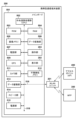
図1は携帯型通信端末装置と印刷装置(MFP)、アクセスポイント(無線基地局とも呼ぶ)を含むシステムの構成を示す図である。携帯型通信端末装置200は、無線LAN(WLAN)通信部すなわち無線通信機能を有する端末装置(情報処理装置)である。携帯型通信端末装置200は、PDA(Personal Digital Assistant)等の個人情報端末、携帯電話、デジタルカメラ等でも良い。印刷装置(MFP)300は、携帯型通信端末装置200と無線通信可能な通信装置であり、読取機能(スキャナ)やFAX機能、電話機能を有していても良い。また、通信装置は、プリンタのみならず、ファクシミリ装置、スキャナ装置、プロジェクタ、携帯端末、スマートフォン、ノートPC、タブレット端末、PDA、デジタルカメラ、音楽再生デバイス、テレビ等にも適用可能である。本実施形態では、通信装置として読取機能と印刷機能を有するMulti Function Printer(MFP:多機能周辺機器)を例にしている。携帯型通信端末装置200及び印刷装置300とは別に設けられる外部のアクセスポイント400は、WLAN通信部を有し、アクセスポイントへの接続を許可した装置同士の通信を中継することで無線インフラモードの通信を提供する。
FIG. 1 is a diagram showing the configuration of a system including a mobile communication terminal device, a printing device (MFP), and an access point (also called a wireless base station). The mobile
携帯型通信端末装置200とMFP300は各々が有するWLAN通信部によって、アクセスポイント400を介した無線インフラモード(無線インフラストラクチャモード)の無線通信を行っても良いし、Wi-Fi Direct(登録商標)やソフトAPモードなどのP2P通信(ピア・ツー・ピア通信)を行うものとしても良い。各モードについては、図7~9を用いて詳細に後述する。なお、携帯型通信端末装置200及びMFP300は、後述するようにWLAN経由で複数の印刷サービスに対応した処理を実行可能である。
The mobile
図2は携帯型通信端末装置200の外観を示す図である。本実施形態では、スマートフォンを例にしている。スマートフォンとは、携帯電話の機能の他に、カメラや、ウェブブラウザ、電子メール機能等を搭載した多機能型の携帯電話のことである。
FIG. 2 is a diagram showing the appearance of the mobile
WLANユニット201はWLANで通信を行うためのユニットである。WLANユニット201は、例えばIEEE802.11シリーズ(IEEE 802.11aやIEEE 802.11b等)に準拠したWLANシステムにおけるデータ(パケット)通信が可能であるものとする。本例では、WLANユニット201は、2.4GHz帯と5GHz帯との両方の帯域で通信可能である。また、WLANユニット201を用いた無線通信では、Wi-Fi Direct(WFD)(登録商標)をベースにした通信、ソフトAPモードによる通信、無線インフラモードによる通信などが可能である。各モードについては、図7~9を用いて詳細に後述する。表示部202は、例えば、LCD方式の表示機構を備えたディスプレイである。操作部203は、タッチパネル方式の操作機構を備えており、ユーザによる操作を検知する。代表的な操作方法には、表示部202がボタンアイコンやソフトウェアキーボードの表示を行い、ユーザがそれらの箇所に触れることによって操作イベントを検知するものがある。電源キー204は電源のオン及びオフをする際に用いるハードキーである。
A
図3はMFP300の外観を示す図である。図3において、原稿台301は、スキャナ(読取部)で読み取らせる原稿を載せるガラス状の透明な台である。原稿蓋302は、スキャナで読取を行う際に原稿を押さえたり、読取の際に原稿を照射する光源からの光が外部に漏れないようにしたりするための蓋である。印刷用紙挿入口303は様々なサイズの用紙をセット可能な挿入口である。印刷用紙挿入口303にセットされた用紙は一枚ずつ印刷部に搬送され、印刷部で印刷を行って印刷用紙排出口304から排出される。操作表示部305は、文字入力キー、カーソルキー、決定キー、取り消しキー等のキーと、LED(発光ダイオード)やLCD(液晶ディスプレイ)などから構成され、ユーザによってMFPとしての各種機能の起動や各種設定を行うことができる。また、タッチパネルで構成されてもよい。WLANアンテナ306は、WLANで通信するためのアンテナが埋め込まれている。MFP300もまた2.4GHz帯と5GHz帯との両方の帯域で通信可能である。
FIG. 3 is a diagram showing the appearance of the
図4は、MFPの操作表示部305の画面表示の一例を模式的に示した図である。図4(a)は、MFPが電源オンし印刷やスキャン等の動作をしていない状態(アイドル状態)を示すホーム画面である。キー操作やタッチパネル操作によりコピーやスキャン、インターネット通信を利用したクラウド機能のメニュー表示から、各種設定、機能実行が可能である。図4(a)のホーム画面からキー操作やタッチパネルの操作によってシームレスに図4(a)とは異なる機能を表示することができる。図4(b)は、その一例であり、プリントやフォト機能の実行やLAN設定の変更が実行可能な画面である。図4(c)は、図4(b)の画面において、LAN設定を選択した際に表示される画面である。この画面から無線インフラモードの有効/無効設定や、WFDやソフトAPモード等のP2Pモードの有効/無効設定など各種のLAN設定変更が実行できる。また、無線LANの周波数帯域やチャネルを設定することもできる。なお無線インフラモードを第1の通信モードと呼び、P2Pモードを第2の通信モードと呼ぶことがある。
FIG. 4 is a diagram schematically showing an example of screen display of the
●携帯型通信端末装置の構成
図5は携帯型通信端末装置200の構成を示すブロック図である。携帯型通信端末装置200は、装置自身のメインの制御を行うメインボード501と、WLAN通信を行うWLANユニット201とを有する。メインボード501において、CPU(中央演算処理部)502は、システム制御部であり、携帯型通信端末装置200の全体を制御する。以降に示す携帯型通信端末装置200の処理はCPU502の制御によって実行される。ROM503は、CPU502が実行する制御プログラムや組込オペレーティングシステム(OS)プログラム等を記憶する。本実施形態では、ROM503に記憶されている各制御プログラムは、ROM503に記憶されている組込OSの管理下で、スケジューリングやタスクスイッチ等のソフトウェア制御を行う。
●Configuration of Portable Communication Terminal FIG. 5 is a block diagram showing the configuration of the
RAM504は、SRAM(Static RAM)等で構成され、プログラム制御変数等のデータを記憶し、また、ユーザが登録した設定値や携帯型通信端末装置200の管理データ等のデータを記憶し、各種ワーク用バッファ領域が設けられている。
The
画像メモリ505は、DRAM(Dynamic RAM)等のメモリで構成され、WLANユニット201を介して受信した画像データや、データ蓄積部513から読み出した画像データをCPU502で処理するために一時的に記憶する。
The
不揮発性メモリ512は、フラッシュメモリ(flash memory)等のメモリで構成され、電源がオフされてもデータを記憶し続ける。尚、これらのようなメモリ構成はこれに限定されるものではない。例えば、画像メモリ505とRAM504を共有させてもよいし、データ蓄積部513にデータのバックアップ等を行ってもよい。また、本実施形態では、画像メモリ505にDRAMを用いているが、ハードディスクや不揮発性メモリ等の他の記憶媒体を使用する場合もあるのでこの限りではない。
The
データ変換部506は、種々の形式のデータの解析や、色変換、画像変換等のデータ変換を行う。電話部507は、電話回線の制御を行い、スピーカ部514を介して入出力される音声データを処理することで電話による通信を実現している。操作部203は、操作部204(図2)の信号を制御する。GPS(Global Positioning System:全地球測位システム)509は、携帯型通信端末装置200の現在の緯度や経度等の位置情報を取得する。表示部202は、表示部203(図2)の表示内容を電子的に制御しており、各種入力操作や、MFP300の動作状況、ステータス状況の表示等を行うことができる。
A
カメラ部511は、レンズを介して入力された画像を電子的に記録して符号化する機能を有している。カメラ部511で撮影された画像はデータ蓄積部513に保存される。スピーカ部514は電話機能のための音声を入力または出力する機能や、その他、アラーム通知等の機能を実現する。電源部515は、携帯可能な電池であり、装置内への電力供給制御を行う。電源状態には、電池に残量が無い電池切れ状態、電源キー205を押下していない電源オフ状態、通常起動している起動状態、起動しているが省電力になっている省電力状態がある。
The
携帯型通信端末装置200はWLANで無線通信することができる。これにより、携帯型通信端末装置200は、MFP等の他デバイスとのデータ通信を行う。この通信部では、データをパケットに変換し、他デバイスにパケット送信を行う。逆に、外部の他デバイスからのパケットを、元のデータに復元してCPU502に対して送信する。WLANユニット201はバスケーブル516介してメインボード501に接続されている。WLANユニット201は規格に準拠した通信を実現するためのユニットである。WLANユニット201は、第1の通信モードとして例えば無線インフラモード、第2の通信モードとしてP2Pモードという、二つの通信モードを同時並行的に提供できる。ただし、それぞれの通信モードで使用する周波数帯域については、ハードウェアの機能あるいは性能から制限されていることもある。メインボード501内の各種構成要素(503~515及び201~203)は、CPU502が管理するシステムバス519を介して、相互に接続されている。
The mobile
●MFPの構成
図6はMFP300の構成を示すブロック図である。MFP300は、装置自身のメインの制御を行うメインボード601と、WLAN通信を行うWLANユニット617とを有する。
●Configuration of MFP FIG. 6 is a block diagram showing the configuration of the
メインボード601において、CPU(中央演算処理部)602は、システム制御部であり、MFP300の全体を制御する。以降に示すMFP300の処理はCPU601の制御によって実行される。ROM603は、CPU602が実行する制御プログラムや組込オペレーティングシステム(OS)プログラム等を記憶する。本実施形態では、ROM603に記憶されている各制御プログラムは、ROM603に記憶されている組込OSの管理下で、スケジューリングやタスクスイッチ等のソフトウェア制御を行う。RAM604は、SRAM(Static RAM)等で構成され、プログラム制御変数等のデータを記憶し、また、ユーザが登録した設定値やMFP300の管理データ等のデータを記憶し、各種ワーク用バッファ領域が設けられている。
In the
不揮発性メモリ605は、フラッシュメモリ(flash memory)等のメモリで構成され、電源がオフされてもデータを記憶し続ける。画像メモリ606は、DRAM(Dynamic RAM)等のメモリで構成され、WLANユニットを介して受信した画像データや、符号復号化処理部611で処理した画像データなどを蓄積する。また、携帯型通信端末装置200のメモリ構成と同様に、このようなメモリ構成はこれに限定されるものではない。データ変換部608は、種々の形式のデータの解析や、画像データから印刷データへの変換等を行う。
The
読取制御部607は、読取部609(例えば、CISイメージセンサ(密着型イメージセンサ))を制御して、原稿上の画像を光学的に読み取る。次に、これを電気的な画像データに変換した画像信号を出力する。このとき2値化処理や中間調処理等の各種画像処理を施してから出力しても良い。
A
操作表示部305は、図4での操作表示部305に対応する。符号復号化処理部611は、MFP300で扱う画像データ(JPEG、PNG等)の符号復号化処理や、拡大縮小処理を行う。給紙部613は印刷のための用紙を保持する。印刷制御部614からの制御で給紙部613から用紙の給紙を行うことができる。特に、給紙部613は、複数種類の用紙を一つの装置に保持するために、複数の給紙部を用意することができる。そして、印刷制御部614により、どの給紙部から給紙を行うかの制御を行うことができる。
The
印刷制御部614は、印刷される画像データに対し、スムージング処理や印刷濃度補正処理、色補正等の各種画像処理を施してから印刷部612に出力する。印刷部612は、例えば、インクタンクから供給されるインクをプリントヘッドから吐出させて画像を印刷するインクジェットプリンタを採用可能である。また、印刷制御部614は印刷部612の情報を定期的に読み出してRAM604の情報を更新する役割も果たす。具体的には、インクタンクの残量やプリントヘッドの状態等のステータス情報を更新することである。
The
MFP300にも、携帯型通信端末装置200と同様にWLANユニット616が搭載されており、機能は携帯型通信端末装置200のWLANユニット201と同等のため、説明は省略する。ここで、WLANユニット616はバスケーブル615を介してメインボード601に接続されている。なお、携帯型通信端末装置200及びMFP300はWFDをベースにした通信が可能であり、ソフトウェアアクセスポイント(ソフトAP)機能を有している。
The
メインボード601内の各種構成要素(ブロック602~614、616~617、619)は、CPU602が管理するシステムバス620を介して、相互に接続されている。
Various components (
<P2P(ピア・ツー・ピア:Peer to Peer)方式について>
WLANにおける通信においてP2P(外部のアクセスポイントを介さずに装置同士がダイレクトで無線LANにより通信する方式)を実現する方式として、複数のモードが考えられる。それぞれのモードでは探索側の機器が同一の機器探索リクエスト(例えば、Probe Requestフレーム)を使用して通信相手となる機器(通信相手装置または対向機という)を探索して発見する。MFP300をP2Pモードで起動する場合、5GHz帯域または2.4GHz帯域の周波数帯域を用いることが可能である。例えばP2Pモードに2.4GHzのみの帯域を設定してMFP300を起動した場合、たとえば携帯型通信端末200などの探索側の機器が5GHz帯域で探索コマンドを送信してもMFP300は応答しない。 P2Pモードのモードとして、以下の2モードが考えられる。
<Regarding the P2P (Peer to Peer) method>
A plurality of modes are conceivable as a method for realizing P2P (a method in which devices directly communicate with each other via a wireless LAN without going through an external access point) in WLAN communication. In each mode, the device on the search side uses the same device search request (for example, a Probe Request frame) to search for and find a device to be a communication partner (referred to as a communication partner device or counterpart device). When activating the
・モードA(ソフトAPモード)
・モードB(Wi-Fi Direct(WFD)(登録商標)モード)
それぞれのモードは、対応している機器と対応していない機器とがあり、また、アプリケーションについても、それぞれのモードで異なることがある。以下、各モードにおける無線の機器探索シーケンスについて、図7、図8を用いて説明する。尚、Wi-Fi Direct(登録商標)による通信機能を有する機器では、その操作部から、その通信機能を実現する専用のアプリケーションを呼び出す。そして、Wi-Fi Direct(登録商標)機器はそのアプリケーションによって提供されるUI(ユーザインターフェース)の画面操作に基づいて、Wi-Fi Direct(登録商標)通信を実行することができる。
・Mode A (soft AP mode)
・Mode B (Wi-Fi Direct (WFD) (registered trademark) mode)
There are devices that support each mode and devices that do not support each mode, and applications may differ depending on each mode. A wireless device search sequence in each mode will be described below with reference to FIGS. 7 and 8. FIG. In addition, in a device having a communication function by Wi-Fi Direct (registered trademark), a dedicated application that realizes the communication function is called from its operation unit. The Wi-Fi Direct (registered trademark) device can perform Wi-Fi Direct (registered trademark) communication based on screen operations of a UI (user interface) provided by the application.
●ソフトAPモードの機器探索シーケンス
図7はモードA(ソフトAPモード)の無線の機器探索シーケンスを示す図である。ソフトAPモードでは、通信を行う機器(例えば、携帯型通信端末装置200とMFP300)との間で、一方の機器(例えば、携帯型通信端末装置200)が、各種サービスを依頼する役割を果たすクライアントとなる。そしてもう一方の機器が、WLANにおけるアクセスポイントの機能をソフトウェアによる設定により実現するソフトAP(例えば、MFP300)となる。
Device Search Sequence in Soft AP Mode FIG. 7 is a diagram showing a wireless device search sequence in mode A (soft AP mode). In the soft AP mode, one device (for example, the portable communication terminal device 200) is a client that performs the role of requesting various services between the devices that perform communication (for example, the portable
ソフトAPモードでは、クライアントは、機器探索リクエスト701によりソフトAPとなる機器を探索する。機器探索リクエスト701を受信したソフトAPは機器探索応答702で返信する。このやり取りによって、クライアント側でソフトAPであるMFP300が発見される。尚、クライアントとソフトAPとの間で無線接続を実現する場合に送受信されるコマンドやパラメータについては、Wi-Fi規格で規定されているものを用いればよく、ここでの説明は省略する。
In the soft AP mode, the client searches for a device that will serve as a soft AP using a
●WFDモードの機器探索シーケンス
図8はモードB(WFDモード)の無線の機器探索シーケンスを示す図である。WFDモードでは、機器探索リクエスト801により通信相手となる機器が探索される。機器探索リクエスト801はWFD属性を有しており、探索の対象がWFDモードの通信機器であることを特定できる。機器探索リクエスト801を受信したMFP300が機器探索応答802を返信すると、クライアント側で、P2Pの通信相手であるMFP300が検出される。P2Pのグループオーナと、P2Pのクライアントの役割を決定した上で、残りの無線接続の処理を行うことになる。この役割決定は、例えばP2PではGO Negotiationに対応する。しかし、後述する、無線インフラモードとWFDモードとが同時に並行動作する場合の周波数帯域について無線チップセットの制約がある場合は、2つのモードのチャンネルを合わせる必要がある。従って、MFP300はWFDモードの親局(Autonomous Group Owner)として固定的に起動することが望ましい。その場合は、役割を決定するためにGO Negotiationの通信は不要となる。MFP300が、WFDモードのGroup Ownerとして起動される時には、MFP300自らが親局としての周波数帯とチャンネルを決定するため、5GHz、2.4GHzいずれかの周波数帯域およびチャネルを選択して用いることが可能である。ソフトAPモードおよびWFDモードを含むP2Pモードを、本例では第2の無線インターフェース又は第2の通信モードと呼ぶこともある。
●WFD Mode Device Search Sequence FIG. 8 is a diagram showing a wireless device search sequence in mode B (WFD mode). In WFD mode, a device to be a communication partner is searched for by a
<無線インフラモードについて>
図9はモードC(無線インフラモード)の無線の機器探索シーケンスを示す図である。無線インフラモードは、通信を行う機器(例えば、携帯型通信端末装置200とMFP300)を、ネットワークを統括する外部の「アクセスポイント」(例えば、アクセスポイント400)と接続し、機器同士が外部のアクセスポイントを介して通信する形態である。言い換えると、外部のアクセスポイントが構築したネットワークを介して機器同士が通信する形態である。無線インフラモードでは、携帯型通信端末機器200は、機器探索リクエスト901によりアクセスポイント400を探索する。アクセスポイント400が機器探索応答902を返信するとアクセスポイントが発見される。携帯型通信端末機器200とMFP300がそれぞれアクセスポイントを発見し、接続することで、アクセスポイントを中継して各デバイス間の通信ができるようになる。尚、機器とアクセスポイントとの間で無線接続を実現する場合に送受信されるコマンドやパラメータについては、Wi-Fi規格で規定されているものを用いればよく、ここでの説明は省略する。無線インフラモードを、本例では第1の無線インターフェース又は第1の通信モードと呼ぶこともある。
<About wireless infrastructure mode>
FIG. 9 is a diagram showing a wireless device search sequence in mode C (wireless infrastructure mode). In the wireless infrastructure mode, communication devices (for example, the mobile
<周波数帯域の制約とセットアップ方法>
1台の無線デバイスで複数の無線インターフェースが同時並行して動作可能であり、かつ、低コストの無線チップセットのハードウェアに、機能上或いは性能上の制約がある場合でも、ユーザの利便性を損なわずに無線を利用するための方法を詳細に説明する。なお、詳細説明の前に、本実施形態の前提となる制約について説明する。
<Frequency band restrictions and setup method>
A single wireless device can operate multiple wireless interfaces in parallel, and user convenience is enhanced even when the hardware of a low-cost wireless chipset has functional or performance limitations. A method for taking advantage of wireless without impairing is described in detail. Prior to the detailed description, constraints that are prerequisites for this embodiment will be described.
無線チップセットが利用するCPUやアンテナが1つしか採用できない、複数の無線インターフェースを同時に動作させるとファームウェアが複雑化する、といったことに起因してこれらの無線利用上の制約が生ずることがある。すなわち、1台の装置内で複数の通信モードが同時並行して動作する場合には、無線チップセットの制約により、利用可能な周波数帯域が限定されることがある。特に、低価格で性能が比較的低い無線チップセットの場合には、利用可能な周波数帯域に制約が伴う場合がある。 These wireless usage restrictions may arise due to the fact that the wireless chipset can only employ one CPU and one antenna, and that operating multiple wireless interfaces at the same time complicates the firmware. That is, when a plurality of communication modes operate concurrently in one device, available frequency bands may be limited due to limitations of the wireless chipset. In particular, in the case of wireless chipsets that are inexpensive and have relatively low performance, the available frequency band may be limited.
第1の制約として、無線インフラモードとP2Pモードを同時並行して動作する場合は、無線インフラモードとP2Pモードでそれぞれ利用するチャンネル(及び周波数帯域)は同一に合わせなければならない場合がある。これは無線チップセットの性能として、1つのCPU、1つのアンテナで動作しているために複数のチャンネルを同時に待ち受け出来ない事に起因する。 As a first constraint, when the wireless infrastructure mode and the P2P mode operate concurrently, the channels (and frequency bands) used in the wireless infrastructure mode and the P2P mode must be the same. This is because the performance of the wireless chipset is that it cannot listen to multiple channels at the same time because it operates with one CPU and one antenna.
次に、第2の制約として、P2Pモード(GroupOwner、もしくはソフトAP)では5GHzのDFS機能を利用できない場合がある。装置が無線基地局として5GHz帯域で動作する場合、常に気象レーダで指定されたレーダ波の使用帯域を監視して干渉波を検知し、かつ検知した場合は即座にチャンネルを移動せねばならない。これがDFS機能であるが、無線チップセットによってはP2PモードでのDFSがその性能を超えてしまうことがあり、第2の制約はそのような事情に起因する。これはP2Pモードが親局として動作しており、DFS機能の親局側の責務としてレーダ波が使用する帯域の監視と、検知した場合のチャンネルの回避機能を担うためである。 Next, as a second constraint, the 5 GHz DFS function may not be available in P2P mode (GroupOwner or soft AP). When a device operates in the 5 GHz band as a radio base station, it must constantly monitor the band of radar waves designated by the weather radar to detect interference waves, and immediately change the channel if it detects an interference wave. This is the DFS function, but depending on the wireless chipset, DFS in P2P mode may exceed its performance, and the second limitation is due to such circumstances. This is because the P2P mode operates as a master station, and the responsibility of the master station of the DFS function is to monitor the band used by radar waves and to avoid channels when detected.
すなわち、無線チップセットに第1と第2の制約がある場合、各無線インターフェースの設定(たとえば単独IF/複数IF)状態によって、利用可能な周波数帯域(2.4GHz帯域、5GHz帯域)が無線インターフェース別に限定されてしまうことがある。利用可能な周波数帯域と、複数インターフェースの同時利用についてトレードオフの関係があるため、これらの制約を無線デバイス内部の制御によって回避することで、無線デバイスのユーザ利便性を損なわずに利用することができる。 That is, when the wireless chipset has the first and second restrictions, the available frequency band (2.4 GHz band, 5 GHz band) depends on the setting state of each wireless interface (for example, single IF/multiple IF). It may be restricted to others. Since there is a trade-off relationship between the available frequency band and the simultaneous use of multiple interfaces, it is possible to use the wireless device without impairing user convenience by avoiding these restrictions through internal control of the wireless device. can.
本実施形態では、第1の制約と第2の制約を回避するために、無線インフラモードとP2Pモードとが同時並行して動作する場合は、装置として通信モードを跨いで(つまり、どちらの通信モードも)2.4GHz帯域のみで動作するよう制御する。また、無線インフラモードのみ単体で動作する場合は、接続先の無線アクセスポイントに合わせて5GHz帯域と2.4GHz帯域のうちいずれかの帯域で動作するよう制御する。また、P2Pモードのみ単体で動作する場合は、2.4GHz帯域のみで動作するよう制御する。無線インフラモードとP2Pモードの設定方法は、初期セットアップ[11]、LAN設定によるIFの有効・無効切り替え、無線の手動セットアップ、無線の自動セットアップ等の方法があるため、順に説明する。 In this embodiment, in order to avoid the first constraint and the second constraint, when the wireless infrastructure mode and the P2P mode operate concurrently, the device straddles the communication modes (that is, which communication mode is used). mode) to operate only in the 2.4 GHz band. Also, when operating only in the wireless infrastructure mode alone, it is controlled to operate in either the 5 GHz band or the 2.4 GHz band according to the wireless access point to which it is connected. Also, when operating only in the P2P mode alone, it is controlled to operate only in the 2.4 GHz band. The wireless infrastructure mode and P2P mode setting methods include initial setup [11], IF enable/disable switching by LAN setting, wireless manual setup, wireless automatic setup, etc., and will be described in order.
<初期起動時のセットアップ>
MFP300は、本体を購入したユーザが初めて電源を投入した際に、工場出荷状態(着荷状態)から初期設定を行うため、通常とは異なる初期起動時専用の処理シーケンス(初期セットアップ)を起動するように構成されている。例えば、MFP300の工場からの出荷時は、印刷部612に、インクタンクやプリントヘッド等が装着されない状態で出荷されている。従って、ユーザが初めて操作する初期起動直後に、同梱されたインクタンクやプリントヘッド等を装着する処理をユーザに促すなど、MFP300を使用可能なように準備する必要があるためである。工場出荷状態のままであることを示す初期起動状態であるかどうかは、不揮発性メモリ605に保存されるフラグ(初期起動フラグ)を用いて制御されており、ユーザ先で使用するための準備が完了すると初期起動フラグの状態が変わり、以後、初期起動時専用の処理シーケンスは起動しないように構成されている。本実施形態では、MFP300では初期起動時に特有の処理を行っていることに着目し、初期起動時の処理に、無線インターフェースの設定を含める。MFP300の初期起動時のIF設定処理シーケンスについて図10および図11を用いて説明する。なお、初期起動時にはIF設定以外の初期セットアップのシーケンスも処理されるが、本実施例に直接関係のないシーケンスについてはここでは図示していない。図11は、MFP300の、特にCPU602によって実行される処理である。
<Initial startup setup>
When the user who has purchased the main unit turns on the power for the first time, the
MFP300のCPU602は、電源を投入されると、ステップS1101で不揮発性メモリ605に保存されている初期起動フラグを参照し、現在、初期起動状態であるかどうかを判断する。この初期起動フラグは、MFP300の工場出荷時に特定の値にあらかじめセットされている。
When the
ステップS1101で初期起動状態ではないと判断した場合は、ステップS1112で、CPU602は、不揮発性メモリに保存されたIFの有効/無効設定に従ってIFの有効化を行う。その後、ステップS1113で、図4(a)に示したような通常の起動時待機画面を表示してユーザの操作を待つ。ステップ1112およびステップS1113は、ユーザの通常使用時の起動処理に相当するシーケンスである。
If it is determined in step S1101 that the IF is not in the initial boot state, in step S1112 the
ステップS1102以降が、本実施形態の処理シーケンスとなっている。ステップS1101で初期起動状態と判断すると、ステップS1102で、CPU602は、図10に示す、ユーザが使用するIFを選択する画面を操作表示部305に表示する。ユーザは、この画面が表示された場面で、自身が使用する予定のIFを画面に表示された項目から選択する。
Step S1102 and subsequent steps constitute the processing sequence of this embodiment. When it is determined in step S1101 that it is in the initial activation state, in step S1102 the
ステップS1103で、CPU602は、ユーザ操作により無線LANが選択されたかどうかを判断する。無線LANが選択されていないと判定した場合、ステップS1110に進む。ステップS1110では、CPU602は、有線LANが選択されたかどうかを判断する。有線LANも選択されていない場合、ステップS1114に進む。ここで、ステップS1114に進むケースは、無線LANも有線LANも選択されず、USBが選択されたケースとなる。ステップS1114で、CPU602は、USBを有効化し、初期起動時のIF設定処理を終える。なお、ここでは図示していないが、インターフェース選択を含む着荷処理シーケンスのすべてを終えると、不揮発性メモリ605に保存されている初期起動フラグの値を、初期起動状態から非初期起動状態へと変更する。そして以後、初期起動処理シーケンスは起動しないようになる。
In step S1103, the
ステップS1110で、CPU602は、有線LANが選択されたと判定すると、ステップS1111で、有線LANを有効化する処理を行う。また、有線LANが有効に設定されたとして、不揮発性メモリ605に設定を保存し、通常起動時に、有効化するIFとして参照される。
When the
一方、ステップS1103で、ユーザ操作により無線LANが選択されたと判断した場合、ステップS1104でCPU602は、ケーブルレスセットアップモードを起動する。ケーブルレスセットアップモードは、無線インフラの無線設定が可能な専用モードである。ケーブルレスセットアップモードのMFP300は、アクセスポイント(親機)と同等の動作をするソフトAPモードとして起動する。その為、パソコンやスマートフォン、タブレット等の外部機器は、クライアント(子機)としてMFP300と簡単に接続出来、通信することが可能である。このケーブルレスセットアップ時における周波数帯域は2.4GHzを使用している。なお、ケーブルレスセットアップモードではソフトAPモードに限らずWFDモードを使用することもできる。ただし、WFDの場合、標準規格上、無線パラメータであるSSIDにランダム生成値の文字列を含ませる必要があり、ソフトAPモードのほうが予約済みSSIDを使用するケーブルレスセットアップには好適である。 パソコンやスマートフォン、タブレット等の外部機器上で動作するLAN設定専用アプリケーションによって、LANに関する知識のあまりないユーザでも、容易にMFP300に接続できるよう構成されている。LAN設定専用アプリケーションによって、設定内容の詳細を知ることなく、アクセスポイントの特定に必要な情報や、接続のためのセキュリティ情報がソフトAPであるMFP300に送られるように構成されている。
On the other hand, if it is determined in step S1103 that the wireless LAN has been selected by the user's operation, the
ケーブルレスセットアップモードでは、ステップS1105で、CPU602は、主に無線インフラモードの接続に必要な設定を受け付ける。パソコンやスマートフォン、タブレット等の外部機器はMFP300と接続後、無線インフラの設定情報を同アプリケーションによってMFP300へ送信する。
In the cableless setup mode, in step S1105, the
MFP300が外部機器から受信する無線設定情報としては、参加したいネットワークを構築している外部アクセスポイントのSSID、当該外部アクセスポイントで使用している周波数帯域(5GHzと2.4GHzのうちいずれか。あるいは周波数帯域に関連する無線チャンネル値でも良い。)、暗号方式、認証方式、等を含む。無線設定情報を受け取ったMFP300は、その後、ソフトAPモードを停止し、無線インフラモードの無線設定処理を実行する。
The wireless setting information that the
設定を受信すると、ステップS1106でCPU602は、ケーブルレスセットアップモードを終了する。そして、ステップS1107では、CPU602は、ステップS1105で受信したLAN設定値に従って、無線インフラモードによる通信を起動し、外部のアクセスポイント400への接続処理を行う。そして、無線インフラモードが有効に設定されたとして、不揮発性メモリ605に設定を保存する。
Upon receiving the settings, the
ステップS1108では、CPU602は、無線チップセットの周波数帯域に関する第2の制約に伴い、複数の無線インターフェースの有効・無効判定を行う。この時、外部機器から送信された無線インフラの周波数帯域(5GHzと2.4GHzのうちいずれか。あるいは周波数帯域に関連する無線チャンネル値を送信する。)に合わせて、MFP300で設定する無線インフラモードの周波数帯域を決定する。つまり、ステップS1105で指示されたLAN設定値に含まれる、外部機器から送信された周波数帯域の情報を元に、MFP300で無線インフラモードとP2Pモードについてそれぞれ有効・無効を判定する。外部機器から無線チャンネル値が送信された場合は、MFP300で、周波数帯域(2.4GHz、5GHz)に変換して、無線インフラモードとP2Pモードについてそれぞれ有効・無効を判定する。ステップS1105で無線インフラの周波数帯域として5GHz帯域を示す情報が送信され、S1107で5GHz周波数帯域の無線アクセスポイントを接続先として無線インフラモードが起動された場合は(S1108でYes)、P2Pモードを無効にしたまま、ステップS1114に進み、USBの有効化を行う。なお、工場出荷時の設定の初期値(デフォルト)として、無線インフラモードもP2Pモードも共に無効な状態に設定されている。一方、ステップS1105でインフラの周波数帯域として2.4GHz周波数帯域を示す情報が送信され、S1107で2.4GHz周波数帯域の無線インフラモードが起動された場合は(S1108でNo)、P2Pモードを2.4GHz周波数帯域で起動し、P2Pモードを有効化する処理を行う(S1109)。P2Pを親局として起動することにより、ビーコンを発信し、ホスト側の端末装置から検出が可能となる。そして、P2Pモードが有効に設定されたとして、不揮発性メモリ605に設定を保存する。なお、無線インフラモードとP2Pモードとの同時動作が可能なプリンタでは、初期起動時のセットアップフロー内において、ユーザが無線インフラモード単体を選択した場合は、プリンタの自主判断によりP2Pモードも有効化し、自動的に両モードが同時動作状態にセットアップされるとよい。つまり、P2Pモードを有効化し設定を保存する処理は、前段のステップS1105において、P2Pモードを有効化する設定を受信しているかどうかに関わらず行なわれる。ただし、無線インフラモードで5GHz帯の外部アクセスポイントが選択された場合に限り、無線チップセットの制約により、P2Pモードを無効のままとする。
In step S1108, the
その後、有線LANが選択されたケースも、無線LANが選択されたケースも、どちらの場合もステップS1114でUSB IFを有効化し、初期起動時のIF設定処理を終える。 After that, in both the case where the wired LAN is selected and the case where the wireless LAN is selected, the USB IF is enabled in step S1114, and the IF setting process at the time of initial startup is completed.
以上のように、初期起動時に本体操作部の操作でWLANが選択された場合において、無線インフラモードによる通信として2.4GHz帯が設定されたなら、無線インフラモードによる通信と、P2Pモード(Wi-Fi Direct(登録商標)又はソフトAP)による通信と、の同時通信が有効となる処理フローとなっている。一方、無線インフラモードによる通信として5GHz帯が設定されたなら、P2Pモード(Wi-Fi Direct(登録商標)又はソフトAP)による通信は無効となり、無線インフラモードのみが有効化される。つまり、5GHz帯が設定されたら、無線インフラモードによる通信と、P2Pモードによる通信と、は同時(並行して)動作できないよう設定される。これによって、複数の通信モードについて同一帯域の同一チャネルを用いなければならない可能性がある第1の制約と、P2PモードではDFSが機能せず、5GHz帯が使用できない可能性があるという第2の制約とに即した設定が、MFPの使用開始する初期セットアップ時に可能となる。 As described above, when WLAN is selected by operating the operation panel of the main unit at the time of initial startup, if the 2.4 GHz band is set for communication in the wireless infrastructure mode, communication in the wireless infrastructure mode and P2P mode (Wi- This is a processing flow in which simultaneous communication using Fi Direct (registered trademark) or software AP) is effective. On the other hand, if the 5 GHz band is set for communication in wireless infrastructure mode, communication in P2P mode (Wi-Fi Direct (registered trademark) or soft AP) is disabled, and only wireless infrastructure mode is enabled. That is, when the 5 GHz band is set, communication in the wireless infrastructure mode and communication in the P2P mode are set so as not to operate simultaneously (in parallel). This leads to the first constraint that the same channel in the same band may have to be used for multiple communication modes, and the second constraint that DFS may not work in P2P mode and the 5 GHz band may not be available. A setting that conforms to the restrictions can be made at the time of initial setup when the MFP is started to be used.
<LAN設定によるIFの有効・無効切り替え>
次に、IFの有効・無効切り替え時における、無線インフラモードとP2Pモードの設定方法について説明する。MFP本体の操作表示部305では、図4(c)に示す本体操作画面あるいはケーブルレスセットアップ経由で、使用するIFの有効/無効を設定可能なように構成されている。本実施形態では、有線LANと無線LANの使用は排他的であり、有線LANを有効にした状態で、同時に無線LANを有効にする事は出来ない。また、逆に無線LANが有効な状態で、同時に有線LANを有効にする事も出来ない。有線LANと無線LANとを同時に無効に設定する事は可能である。USB IFはユーザによる設定で無効には出来ないが、起動時に常に有効化され、有線LANあるいは無線LANと同時に使用可能な構成となっている。無線LANには、P2Pモードと、無線インフラモードの設定があり、個別に独立して有効/無効が設定出来るようになっている。P2Pモードと無線インフラモードを同時に有効に設定する事が可能である。その際にMFP300は、P2Pによる通信と無線インフラによる通信を同時に行う事が出来るようになる。設定した有効/無効の状態は不揮発性メモリ605に保存され、次回の起動時にも参照されて、保存された情報に基づき各IFが有効化される。本体のLAN設定項目を初期化した際には、P2Pモードおよび無線インフラモードは無効となる。また、有線LANも無効となり、有線も無線もLANは使用しない状態となる。LAN設定を初期化したユーザは、所望のIFを個別に有効に設定変更して使用する事になる。
<Enable/disable switching of IF by LAN setting>
Next, a method for setting the wireless infrastructure mode and the P2P mode at the time of enabling/disabling the IF will be described. The
図12を用いて、IFの切り替えについて説明する。図12はLAN設定値として、通信モードと周波数帯域との設定可能な組み合わせを示す。図12によれば、通信モード設定には3通りの組み合わせがあるが、使用する周波数帯域の設定と組み合わせて通信モード設定1から通信モード設定4まで、4通りの設定があり得る。 IF switching will be described with reference to FIG. FIG. 12 shows possible combinations of communication modes and frequency bands as LAN setting values. According to FIG. 12, there are three combinations of communication mode settings, and four settings from communication mode setting 1 to communication mode setting 4 are possible in combination with setting of the frequency band to be used.
通信モード設定1は、無線インフラモードが有効、P2Pモードが無効に設定されたパターンである。例えば、LAN無効状態から、無線インフラモードで外部の無線アクセスポイントとのセットアップを行い、2.4GHz帯域で外部の無線アクセスポイントと接続完了した時の無線設定を保存する。 Communication mode setting 1 is a pattern in which the wireless infrastructure mode is enabled and the P2P mode is disabled. For example, from the LAN disabled state, setup with an external wireless access point is performed in the wireless infrastructure mode, and the wireless settings when connection with the external wireless access point is completed in the 2.4 GHz band are saved.
通信モード設定2は、通信モード設定1と同様に無線インフラモードが有効、P2Pモードが無効に設定されたパターンである。例えば、LAN無効状態から、無線インフラモードで外部の無線アクセスポイントとのセットアップを行い、5GHz帯域で無線アクセスポイントと接続完了した時の無線設定を保存する。また、初期起動時に図11のステップS1105で無線インフラモードを指定して、ステップS1108で5GHz帯域の外部の無線アクセスポイントと接続した場合は通信モード設定2で保存される。
Communication mode setting 2 is a pattern in which the wireless infrastructure mode is enabled and the P2P mode is disabled, similarly to
通信モード設定3は、無線インフラモードが無効、P2Pモードが有効に設定されたパターンである。例えば、LAN無効状態から、図4(c)の操作表示部で、P2Pモードを無効設定から有効設定に切り替えると通信モード設定3で保存される。 Communication mode setting 3 is a pattern in which the wireless infrastructure mode is disabled and the P2P mode is enabled. For example, when the P2P mode is switched from the disabled setting to the enabled setting in the operation display section of FIG. 4C from the LAN disabled state, communication mode setting 3 is saved.
通信モード設定4は、無線インフラモードが無効、P2Pモードが有効に設定されたパターンである。
例えば、通信モード設定1から、図4(c)の操作表示部でP2Pモードを無効設定から有効設定に切り替えると通信モード設定4で保存される。また、初期起動時に図11のステップS1105で無線インフラモードをLAN設定値として指定して、ステップS1108で2.4GHz帯域で接続した場合は、ステップ1109でP2Pモードを2.4GHzで起動し、通信モード設定4で保存される。
Communication mode setting 4 is a pattern in which the wireless infrastructure mode is disabled and the P2P mode is enabled.
For example, from communication mode setting 1, when the P2P mode is switched from disabled setting to enabled setting in the operation display section of FIG. 4C, communication mode setting 4 is saved. Also, when the wireless infrastructure mode is designated as the LAN setting value in step S1105 of FIG. Saved in
以上のように、本実施形態で許容される無線通信の設定では、5GHz帯は無線インフラモードのみについて使用され、P2Pモードでは使用されない。なおかつ、無線インフラモードとP2Pモードとで使用する周波数帯域は同一である。なおMFP300の初期起動時に、図11の手順で設定される通信モードは、S1105で5GHz帯が指定された場合には通信モード設定2と同じ設定となり、2.4GHz帯が指定された場合には通信モード設定4と同じの設定となる。
As described above, in the wireless communication settings allowed in this embodiment, the 5 GHz band is used only in the wireless infrastructure mode and not in the P2P mode. Moreover, the same frequency band is used in the wireless infrastructure mode and the P2P mode. When the
●P2Pモードの有効化
無線チップセットの制約が、IF切り替えの障壁になるパターンとして、通信モード設定2から別の通信モード設定への切り替えがある。通信モード設定2の状態は無線インフラモードが5GHzになっており、図4(c)の操作表示部で、P2Pモードを無効設定から有効設定に切り替えると、無線チップセットの第一と第2の制約が障壁となる。すなわち第1の制約により、二つのモードを同時並行で動作させるためには、無線インフラモードのチャンネル・周波数帯域に合わせてP2Pモードも5GHzで起動しなければならない。しかしながら、第2の制約により、P2Pモードは5GHzのDFS機能が使えずそのため2.4GHzでしか起動できない。このため、ユーザが明示的に設定したP2Pモードへの設定変更を優先して、P2Pモードが使える通信モード設定3に切り替えるフローチャートが図13である。図13は、MFP300の、特にCPU602によって実行される処理である。
●Enabling P2P mode Switching from communication mode setting 2 to another communication mode setting is a pattern in which wireless chipset restrictions become an obstacle to IF switching. In the state of communication mode setting 2, the wireless infrastructure mode is set to 5 GHz, and when the P2P mode is switched from disabled setting to enabled setting in the operation display section of FIG. Constraints are barriers. That is, due to the first constraint, in order to operate the two modes concurrently, the P2P mode must also be activated at 5 GHz in accordance with the channel/frequency band of the wireless infrastructure mode. However, due to a second constraint, the P2P mode cannot use the 5GHz DFS feature, so it can only activate at 2.4GHz. For this reason, FIG. 13 is a flowchart showing a switching to communication mode setting 3 that allows the P2P mode to be used, prioritizing the setting change to the P2P mode explicitly set by the user. FIG. 13 shows processing executed by the
図13のステップS1301で、CPU602は、図4(c)の操作表示部におけるユーザ操作を受けて、P2Pモードを無効設定から有効設定に切り替える指示を実行する。ステップS1302で、CPU602は、無線インフラ設定の有効・無効判定を行う。無線インフラが無効の場合は、ステップS1306に進み、ステップS1306でCPU602は、P2Pモードを2.4GHz帯域のチャンネルを指定して起動する。無線インフラが有効の場合は、ステップS1303に進み、CPU602は、LAN設定として既に保存されている無線インフラモードについて設定した周波数帯が5GHzか否かの判定を行う。無線インフラモードの帯域設定が5GHzの場合は、ユーザが明示的に設定したP2Pモードへの設定変更を優先して、CPU602は、P2Pモードが使える通信モード設定3に切り替える。そのため、CPU602は、ステップS1304で無線インフラモードが無効になることを、たとえば警告メッセージを表示等により出力して警告(通知)した上で、ステップS1305で無線インフラモードを無効にすることが好ましい。そしてS1306でCPU602は、所望のP2Pモードを2.4GHzで起動する。ステップS1303で無線インフラ設定が2.4GHzの場合はステップS1307に進み、無線インフラモードと同じチャンネル及び2.4GHzの周波数帯をP2Pモードに設定して、ステップ1306に進みP2Pモードを起動する。
In step S1301 of FIG. 13, the
上記手順により、P2Pモードを有効化する際に、第1の制約および第2の制約とも満たしたうえで、P2Pモードの通信を開始することができる。 According to the above-described procedure, when enabling the P2P mode, it is possible to start communication in the P2P mode after satisfying both the first constraint and the second constraint.
●インフラストラクチャモードの有効化
無線チップセットの制約が、IF切り替えの障壁になるパターンとして、通信モード設定3から別の5GHzを使用する通信モード設定に変更するケースがある。通信モード設定3の状態はP2Pモードが2.4GHzになっており、図4(c)の操作表示部で、過去に5GHz帯でセットアップした無線インフラモードを無効設定から有効設定に切り替えると、無線チップセットの第1と第2の制約が障壁となる。すなわち第1の制約により、無線インフラモードとP2Pモードとを同時並行で動作させるためには、無線インフラモードのチャンネル・周波数帯域に合わせてP2Pも5GHzで起動しなければならない。しかしながら、第2の制約により、P2Pモードは5GHzのDFS機能が使えず2.4GHzでしか起動できない。このため、ユーザが明示的に設定した無線インフラモードへの設定変更を優先して、通信モード設定2に切り替えるフローチャートが図14である。図14は、MFP300の、特にCPU602によって実行される処理である。
●Validation of infrastructure mode There is a case where the communication mode setting is changed from communication mode setting 3 to another communication mode setting using 5 GHz as a pattern that becomes an obstacle to IF switching due to restrictions of the wireless chipset. In the state of communication mode setting 3, the P2P mode is set to 2.4 GHz, and when the wireless infrastructure mode set up in the past in the 5 GHz band is switched from disabled to enabled in the operation display section of FIG. The first and second limitations of the chipset are barriers. That is, according to the first constraint, in order to operate the wireless infrastructure mode and the P2P mode concurrently, P2P must also be activated at 5 GHz in accordance with the channel/frequency band of the wireless infrastructure mode. However, due to a second constraint, the P2P mode can only activate at 2.4 GHz without DFS functionality at 5 GHz. For this reason, FIG. 14 is a flowchart for switching to communication mode setting 2 with priority given to setting change to wireless infrastructure mode explicitly set by the user. FIG. 14 shows processing executed by the
図14のステップS1401で、CPU602は、図4(c)の操作表示部におけるユーザ操作を受けて、無線インフラモードを無効設定から有効設定に切り替える指示を実行する。ステップS1402でCPU602は、P2Pモード設定の有効・無効判定を行う。P2Pモードが無効の場合は、ステップS1406に進み、ステップS1406でCPU602は、保存されている周波数帯とチャンネルを指定して無線インフラモードを起動する。図12の通信モード設定3のようにP2Pモードが有効の場合は、ステップS1403に進み、LAN設定として既に保存されている無線インフラモードについての設定されている周波数帯が5GHzか否かの判定を行う。無線インフラモードの帯域の設定が5GHzの場合は、ユーザが明示的に設定した無線インフラモードへの設定変更を優先する。そこで通信モード設定2に切り替えるため、ステップS1404でCPU602は、P2Pモードが無効になることを、たとえば警告メッセージを表示等により出力して警告した上で、ステップS1405でP2Pモード設定を無効にすることが好ましい。そしてステップS1406でCPU602は、所望の無線インフラモードを5GHzで起動する。ステップS1403でCPU602は、無線インフラ設定が2.4GHzの場合はステップS1407に進み、CPU602は、無線インフラモードと同じ2.4GHzの周波数帯かつ同じチャンネルをP2Pモードに設定してステップ1406でCPU602は、P2Pモードを起動する。
In step S1401 of FIG. 14, the
上記手順により、無線インフラモードを有効化する際にも、第1の制約および第2の制約とも満たしたうえで、無線インフラモードの通信を開始することができる。 According to the above procedure, even when the wireless infrastructure mode is activated, the communication in the wireless infrastructure mode can be started after both the first constraint and the second constraint are satisfied.
<無線の手動セットアップ>
次に、無線の手動セットアップ時における、無線インフラモードとP2Pモードの設定方法について説明する。図15はMFP300で実施する無線インフラの手動セットアップを示すフローチャート図である。手動セットアップでは、ユーザ指示により検索(あるいは探索)した周囲の無線アクセスポイント一覧がMFPの操作表示部305に表示され、ユーザが無線アクセスポイントを検索結果から手動で選択する。図15は、MFP300の、特にCPU602によって実行される処理である。
<Wireless manual setup>
Next, a method for setting the wireless infrastructure mode and the P2P mode during manual wireless setup will be described. FIG. 15 is a flow chart diagram showing manual setup of the wireless infrastructure implemented in
ステップ1501で、CPU602は、MFP300の操作表示部305へのユーザ操作を受けて、無線インフラの手動セットアップの指示が実行する。MFP300が無線LAN無効状態である場合は、まだ無線IFが起動されていないため、ステップS1502でCPU602は、無線IFを起動する。たとえば図11の手順で、有線LANまたはUSBが選択された場合に無線LAN無効状態となる。
In step 1501,
ステップ1503では、CPU602は、WLANユニット616を用いて周囲の無線アクセスポイントを検索する。図9ではMFP300から機器探索リクエスト903を送信して、周囲に存在する外部の無線アクセスポイントからは機器探索応答904が応答される。機器探索リクエストは、同コマンド内でESSID、BSSIDを指定せずにブロードキャストすることで周囲にある無線アクセスポイントが検出される。また、5GHz、2.4GHzの双方の帯域について、全ての利用可能なチャネルに対して順次ブロードキャスト検索する。この際、2.4GHz、5GHzの順番で小さいチャンネルから検索しても、その逆に、5GHz、2.4GHzの順番で大きいチャンネルから検索してもよい。無線アクセスポイント400から返信される機器探索応答904には、ESSID、BSSID、チャネル等の情報が含まれており、これを元にMFPの操作表示部305に無線アクセスポイントの検索結果を一覧表示する。
At step 1503 ,
検索結果の一覧表示から、ユーザがステップS1504でユーザは所望の無線アクセスポイントを選択することができ、CPU602はその選択結果を受けつける。検索結果の一覧表示として、無線アクセスポイントのESSIDを識別子として表示するのが分かりやすいが、その他、暗号情報(WPA2、WPA、WEP等)、BSSID、チャンネル、周波数帯、電波強度などの情報を併記しても良い。
In step S1504, the user can select a desired wireless access point from the list display of the search results, and
ステップS1505では、CPU602は、選択された無線アクセスポイントに、MFP300から無線インフラモードで接続する。CPU602は、既にP2P設定が有効になっているか否かをステップS1506で判定する。すでにP2P設定が有効になっている場合は、CPU602は、5GHz帯域で無線アクセスポイントに接続したかどうかをステップS1506で判定する。2.4GHz帯域で接続した場合は、実施形態1では無線インフラモードで取得したチャンネルに合わせて、ステップ1508でCPU602は、P2Pモードを有効化する。5GHz帯域で接続した場合は、実施形態1ではステップS1509でP2Pモードが無効になることを、たとえば警告メッセージを表示等により出力して警告表示した上で、ステップS1510でP2Pモードを無効化する。
In step S1505,
このように実施形態1では、無線チップセットの第1と第2の制約があるため、2.4GHzを優先して接続することで無線インフラモードとP2Pモードの同時利用を阻害せずにユーザ利用できる利点がある。また、5GHz帯域で無線アクセスポイントと接続した場合は、ユーザに警告表示した上で、P2Pモードを無効にすることで制約を回避したLAN設定になるよう誘導する。またアクセスポイントの探索機能を用いてアクセスポイントを探索した場合にも、制約を回避して利用周波数帯域を設定することができる。 As described above, in the first embodiment, since there are the first and second restrictions of the wireless chipset, the user can use the wireless infrastructure mode and the P2P mode simultaneously without hindering the simultaneous use of the wireless infrastructure mode and the P2P mode by giving priority to the connection of 2.4 GHz. There are advantages to be had. Also, when connecting to a wireless access point in the 5 GHz band, a warning is displayed to the user, and the P2P mode is disabled to guide the user to a LAN setting that avoids restrictions. Moreover, even when an access point is searched for using an access point search function, it is possible to avoid restrictions and set the frequency band to be used.
<無線の自動セットアップ(2.4GHz帯域優先)>
次に、無線の自動セットアップ時において2.4GHz帯を優先時における、無線インフラモードとP2Pモードの設定方法について説明する。自動セットアップは、接続先の無線アクセスポイントをプッシュボタンやPINコード方式で自動で選択できるため自動セットアップと呼んでいる。具体的にはWPS(Wi-Fi Protected Setup)(商標)、AOSS(商標)、らくらく無線スタート(登録商標)、等の方法がある。無線の自動セットアップ時には、無線アクセスポイントから取得した無線パラメータの周波数情報の内から、2.4GHz帯域と5GHz帯域とのうちいずれかを優先した順番で接続を試みる必要がある。実施形態1では、無線チップセットの第2の制約があるため、2.4GHzを優先して接続する方が無線インフラモードとP2Pモードの同時利用の条件を満たせる可能性が高められる。従って、まず2.4GHzを優先して接続を試みる方法について説明する。
<Wireless automatic setup (2.4 GHz band priority)>
Next, a method for setting the wireless infrastructure mode and the P2P mode when the 2.4 GHz band is prioritized during automatic wireless setup will be described. Automatic setup is called automatic setup because the wireless access point to be connected to can be automatically selected by a push button or PIN code method. Specifically, there are methods such as WPS (Wi-Fi Protected Setup) (trademark), AOSS (trademark), Rakuraku Wireless Start (registered trademark), and the like. At the time of automatic wireless setup, it is necessary to attempt connection in the order in which priority is given to either the 2.4 GHz band or the 5 GHz band from among the frequency information of the wireless parameters acquired from the wireless access point. In the first embodiment, since there is a second restriction of the wireless chipset, it is more likely that the condition for simultaneous use of the wireless infrastructure mode and the P2P mode can be satisfied by giving priority to 2.4 GHz for connection. Therefore, first, a method of attempting connection with priority given to 2.4 GHz will be described.
図16、図17はMFP300で実施する無線インフラモードの自動セットアップを示すフローチャート図である。図16のステップS1601で、MFP300は、ユーザのキー操作などにより無線インフラモードの自動セットアップモードに移行する。図16及び図17は、MFP300の、特にCPU602によって実行される処理である。
16 and 17 are flowcharts showing automatic setup of the wireless infrastructure mode performed by the
ステップS1602で、MFP300は、無線インフラモードの自動セットアップ中の外部のアクセスポイント400と接続されたか否かを判定する。
In step S1602, the
接続された場合は(ステップS1602でYES)、ステップS1603でアクセスポイント400からn個の無線接続プロファイルを受信したか否かを判定する(nは正の整数)。1つの無線接続プロファイルは、「SSID」「周波数」「認証方式」「暗号方式」「パスフレーズ」から構成されている情報である。 If connected (YES in step S1602), it is determined in step S1603 whether or not n wireless connection profiles have been received from the access point 400 (n is a positive integer). One wireless connection profile is information composed of "SSID", "frequency", "authentication method", "encryption method", and "passphrase".
一方、接続されていない場合は(ステップS1602でNO)、ステップS1605で所定のタイムアウトが発生しているか否かを判定する。タイムアウトが発生した場合は(ステップS1605でYES)、MFP300は操作表示部305にエラー画面を表示し、無線インフラモードの自動セットアップを終了する。一方、タイムアウトが発生していない場合は(ステップS1605でNO)、ステップS1602へ戻り、無線インフラモードの自動セットアップ中のアクセスポイント400と接続されるのを待つ。
On the other hand, if it is not connected (NO in step S1602), it is determined in step S1605 whether or not a predetermined timeout has occurred. If a timeout has occurred (YES in step S1605), the
アクセスポイント400からn個(すなわち少なくとも一つ)の無線接続プロファイルを受信した場合は(ステップS1603でYES)、ステップS1604で無線接続プロファイルカウンタ変数mを「1」に初期化する。 If n (that is, at least one) wireless connection profiles have been received from the access point 400 (YES in step S1603), the wireless connection profile counter variable m is initialized to "1" in step S1604.
一方、アクセスポイント400からn個の無線接続プロファイルを受信していない場合は(ステップS1603でNO)、ステップS1606で所定のタイムアウトが発生しているか否かを判定する。タイムアウトが発生した場合は(ステップS1606でYES)、MFP300は操作表示部305にエラー画面を表示し、無線インフラモードの自動セットアップを終了する。一方、タイムアウトが発生していない場合は(ステップS1606でNO)、ステップS1603へ戻り、引き続きアクセスポイント400からn個の無線接続プロファイルが送信されてくるのを待つ。
On the other hand, if n wireless connection profiles have not been received from the access point 400 (NO in step S1603), it is determined in step S1606 whether or not a predetermined timeout has occurred. If a timeout has occurred (YES in step S1606), the
ステップS1607で、m番目の無線接続プロファイルの周波数が2.4GHz帯域か否かを判定する。2.4GHz帯域の場合(ステップS1607でYES)、ステップS1608でMFP300のRAM604の2.4GHzの接続情報を格納する領域に、m番目の無線接続プロファイルを保存する。
In step S1607, it is determined whether or not the frequency of the m-th wireless connection profile is in the 2.4 GHz band. In the case of the 2.4 GHz band (YES in step S1607), in step S1608, the m-th wireless connection profile is saved in the area storing connection information for 2.4 GHz of the
一方、2.4GHz帯域ではない場合(ステップS1607でNO)、ステップS1611でm番目の無線接続プロファイルの周波数が5GHz帯域か否かを判定する。5GHzの場合は(ステップS1611でYES)、ステップS1612でMFP300のRAM604の5GHz帯域の接続情報を格納する領域に、m番目の無線接続プロファイルを保存する。一方、5GHz帯域ではない場合は(ステップS1611でNO)、後述する(ケース2)にて詳細を説明する。
On the other hand, if it is not in the 2.4 GHz band (NO in step S1607), it is determined in step S1611 whether or not the frequency of the m-th wireless connection profile is in the 5 GHz band. In the case of 5 GHz (YES in step S1611), in step S1612, the m-th wireless connection profile is saved in the area storing connection information for the 5 GHz band of the
ステップS1609で、無線接続プロファイルカウンタ変数mを1つインクリメントする。ステップS1610で、n(無線接続プロファイル数)とm(無線接続プロファイルカウンタ変数)の大小関係を判定する。n(無線接続プロファイル数)がm(無線接続プロファイルカウンタ変数)より小さい場合は(ステップS1610でYES)、図17のステップS1717に進む。そこでMFP300のRAM604の2.4GHz帯域の接続情報を格納する領域に、無線接続プロファイルがあるか否か判定する。
In step S1609, the wireless connection profile counter variable m is incremented by one. In step S1610, the magnitude relationship between n (number of wireless connection profiles) and m (wireless connection profile counter variable) is determined. If n (number of wireless connection profiles) is smaller than m (wireless connection profile counter variable) (YES in step S1610), the process proceeds to step S1717 in FIG. Therefore, it is determined whether or not there is a wireless connection profile in the area storing connection information for the 2.4 GHz band of the
一方、n(無線接続プロファイル数)がm(無線接続プロファイルカウンタ変数)より大きい場合、あるいはn(無線接続プロファイル数)とm(無線接続プロファイルカウンタ変数)が同じ場合は(ステップS1610でNO)、ステップS1607に戻る。そこでm番目の無線接続プロファイルの周波数が2.4GHz帯域か否かを判定する。以降、ステップS1610がYESとなるまで処理を繰り返す。 On the other hand, if n (number of wireless connection profiles) is greater than m (wireless connection profile counter variable), or if n (number of wireless connection profiles) and m (wireless connection profile counter variable) are the same (NO in step S1610), Return to step S1607. Therefore, it is determined whether or not the frequency of the m-th wireless connection profile is in the 2.4 GHz band. Thereafter, the process is repeated until step S1610 becomes YES.
尚、ステップS1608でMFP300のRAM604の2.4GHz帯域の接続情報を格納する領域にm番目の無線接続プロファイルを保存する際、例えば、認証方式、暗号方式の強度順に保存しても良い。また、ステップS1612でMFP300のRAM604の5GHz帯域の接続情報を格納する領域にm番目の無線接続プロファイルを保存する際も、例えば、認証方式、暗号方式の強度順に保存しても良い。
When saving the m-th wireless connection profile in the area for storing the connection information of the 2.4 GHz band of the
図17のステップS1717で、MFP300のRAM604の2.4GHz帯域の接続情報を格納する領域に無線接続プロファイルが保存されているか否か判定する。保存されている場合は(ステップS1717でYES)、ステップS1718で2.4GHz帯域の接続情報を指定して無線インフラモードの接続処理を実施する。この接続処理でMFP300は、テーブルの上位の無線接続プロファイルから順に接続処理を実施する。
In step S1717 of FIG. 17, it is determined whether or not a wireless connection profile is saved in the area for storing connection information for the 2.4 GHz band of the
ステップS1719で、2.4GHz帯域で接続が成功したか否かを判定する。成功した場合は(ステップS1719でYES)、ステップS1720でMFP300の不揮発性メモリ605からP2Pモード設定を読み込み、設定が有効か無効か判定する。P2Pモード設定が有効な場合は(ステップS1720でYES)、MFP300はステップS1721でP2Pモードを起動する。一方、P2Pモード設定が無効の場合は(ステップS1720でNO)、そのまま終了する。
In step S1719, it is determined whether or not the connection has succeeded in the 2.4 GHz band. If successful (YES in step S1719), the P2P mode setting is read from the
一方、ステップS1717でMFP300のRAM604の2.4GHz帯域の接続情報を格納する領域に無線接続プロファイルが保存されていない場合(ステップS1717でNO)、ステップS1722に分岐する。
On the other hand, if the wireless connection profile is not saved in the area storing the connection information of the 2.4 GHz band of the
ステップS1722で、MFP300のRAM604の5GHz帯域の接続情報を格納する領域に無線接続プロファイルが保存されているか否かを判定する。保存されている場合は(ステップS1722でYES)、ステップS1723で5GHz帯域の接続情報を指定して無線インフラモードの接続処理を実施する。この接続処理でMFP300は、テーブルの上位の無線接続プロファイルから順に接続処理を実施する。
In step S1722, it is determined whether or not a wireless connection profile is saved in the area storing connection information for the 5 GHz band of the
一方、保存されていない場合は、(ステップS1722でNO)、ステップS1720でMFP300の不揮発性メモリ605からP2Pモード設定を読み込み、設定が有効か無効か判定する。P2Pモード設定が有効な場合は(ステップS1720でYES)、MFP300はステップS1715でP2Pモードを起動する。一方、P2Pモード設定が無効の場合は(ステップS1720でNO)、そのまま終了する。
On the other hand, if not saved (NO in step S1722), the P2P mode setting is read from the
ステップS1724で、5GHz帯域での接続が成功したか否かを判定する。成功した場合は(ステップS1724でYES)、ステップS1725でMFP300の不揮発性メモリ605からP2Pモード設定を読み込み、設定が有効か無効か判定する。P2Pモード設定が有効な場合は(ステップS1725でYES)、MFP300は、ステップS1726でユーザに操作画面にP2Pモードが無効になることを、たとえば警告メッセージを表示等により出力して警告を表示した上で、ステップS1727でP2Pモード設定を無効にする。ユーザに操作画面上で警告する内容としては、ユーザ操作とは直接関係のないP2Pモード設定が自動で無効化される点を通知すべきである。P2Pモード設定が無効の場合は(ステップS1725でNO)、そのまま終了する。
In step S1724, it is determined whether or not the connection in the 5 GHz band has succeeded. If successful (YES in step S1724), the P2P mode setting is read from the
一方、接続が失敗した場合は(ステップS1724でNO)、MFP300は操作表示部305にエラー画面を表示し、無線インフラモードの自動セットアップを終了する。
On the other hand, if the connection fails (NO in step S1724),
以上の方法により、WPS(Wi-Fi Protected Setup)、AOSS、らくらく無線スタート(登録商標)で共通の処理フローを用いて、2.4GHz帯域又は5GHz帯域の無線セットアップを実現する。無線セットアップ完了時の周波数帯を保存領域に記憶しておき、2.4GHzと5GHzとのうちいずれかの帯域に固定している。2.4GHz帯と5GHz帯の両方についてアクセスポイントを発見した場合には、2.4GHzを優先的に接続することで、P2Pとの同時利用の機会を増大させることができる。無線が切断された際の再接続後に、意図せず無線チップセットの第1の制約、あるいは第2の制約に陥り無線インフラモードあるいはP2Pモードが使えなくなってしまうことを防止している。 According to the above method, WPS (Wi-Fi Protected Setup), AOSS, and Rakuraku Wireless Start (registered trademark) use a common processing flow to realize wireless setup for the 2.4 GHz band or 5 GHz band. The frequency band at the completion of wireless setup is stored in a storage area and fixed to either 2.4 GHz or 5 GHz. When an access point is found for both the 2.4 GHz band and the 5 GHz band, by preferentially connecting to the 2.4 GHz band, it is possible to increase opportunities for simultaneous use with P2P. This prevents the wireless infrastructure mode or the P2P mode from being unusable due to unintentional falling into the first or second restriction of the wireless chipset after reconnection when the wireless connection is disconnected.
<無線の自動セットアップ(5GHz帯域優先)>
次に、無線の自動セットアップ時において5GHz帯を優先時における、無線インフラモードとP2Pモードの設定方法について説明する。無線の自動セットアップ時には、無線アクセスポイントから取得した無線パラメータの周波数情報の内から、2.4GHz/5GHzのいずれかの帯域を優先した順番で接続を試みる必要がある。上述の2.4GHz帯優先の例では、無線チップセットの第2の制約があるため、2.4GHzを優先して接続する方が無線インフラモードとP2Pモードの同時利用の条件を満たせる可能性が高められることから、2.4GHz優先で接続した。しかしながら、複数の無線インターフェースの同時利用よりも、5GHzの周波数帯利用を優先したいユーザも存在する。ここでは5GHzを優先して接続を試みる方法について説明する。
<Wireless automatic setup (5 GHz band priority)>
Next, a method for setting the wireless infrastructure mode and the P2P mode when the 5 GHz band is prioritized during automatic wireless setup will be described. At the time of automatic wireless setup, it is necessary to attempt connection in the order of priority given to either 2.4 GHz or 5 GHz band from among the frequency information of the wireless parameters acquired from the wireless access point. In the above example of prioritizing the 2.4 GHz band, there is a second restriction on the wireless chipset, so connecting with priority on the 2.4 GHz band may satisfy the conditions for simultaneous use of the wireless infrastructure mode and the P2P mode. Since it can be increased, it was connected with 2.4 GHz priority. However, some users prefer to use the 5 GHz frequency band over simultaneous use of multiple wireless interfaces. Here, a method of attempting connection with priority given to 5 GHz will be described.
5GHz優先で無線アクセスポイントに接続する場合も、<無線の自動セットアップ(2.4GHz優先)>で説明した図16のステップS1601~S1616と同様に無線接続プロファイルの受信と保存処理を行う。ただし、5GHz優先にするため、ステップS1607、S1608、S1613の処理を2.4GHz帯域ではなく5GHz帯域の処理に置き換える。また、ステップS1611、S1612、S1615の処理を5GHz帯域ではなく2.4GHz帯域に置き換えることで5GHz優先とする。 When connecting to a wireless access point with 5 GHz priority, reception and storage of a wireless connection profile are performed in the same manner as steps S1601 to S1616 in FIG. 16 described in <Wireless Automatic Setup (2.4 GHz Priority)>. However, in order to prioritize 5 GHz, the processing in steps S1607, S1608, and S1613 is replaced with processing for the 5 GHz band instead of the 2.4 GHz band. Also, priority is given to 5 GHz by replacing the processing of steps S1611, S1612, and S1615 with the 2.4 GHz band instead of the 5 GHz band.
5GHz優先で無線アクセスポイントに接続する場合も、<無線の自動セットアップ(2.4GHz優先)>で説明した図17のステップS1717~S1727と同様に保存された無線接続プロファイルに従った無線インフラモードの接続処理を行う。ただし、5GHz優先にするため、ステップS1717、S1718は2.4GHz帯域ではなく5GHz帯域の処理に置き換える。また、ステップS1722、S1723の処理を5GHz帯域ではなく2.4GHz帯域に置き換えることで5GHz優先とする。 Even when connecting to a wireless access point with 5 GHz priority, the wireless infrastructure mode is set according to the wireless connection profile saved in the same manner as steps S1717 to S1727 in FIG. Perform connection processing. However, in order to prioritize 5 GHz, steps S1717 and S1718 are replaced with processing for the 5 GHz band instead of the 2.4 GHz band. Also, priority is given to 5 GHz by replacing the processing of steps S1722 and S1723 with the 2.4 GHz band instead of the 5 GHz band.
また、ステップS1726の警告表示は5GHz専用の警告のため不要となり、代わりに5GHz帯域の処理において、ステップS1721の直前のタイミングで警告表示をするのが望ましい。さらに、ステップS1721ではP2Pモードを無効化し、ステップS1727ではP2Pモードを、無線インフラモードと同じ帯域およびチャネルで起動する。すなわち、ステップS1719~S1721は2.4GHz帯域に接続成功後の処理としてセットで実施する。ステップS1725~S1727は5GHz帯域に接続成功後の処理としてセットで実施する。 Further, the warning display in step S1726 is unnecessary because it is a warning dedicated to 5 GHz. Instead, it is desirable to display the warning immediately before step S1721 in the processing of the 5 GHz band. Further, the P2P mode is disabled in step S1721, and the P2P mode is activated in the same band and channel as the wireless infrastructure mode in step S1727. That is, steps S1719 to S1721 are performed as a set as processing after successful connection to the 2.4 GHz band. Steps S1725 to S1727 are performed as a set as processing after successful connection to the 5 GHz band.
以上の処理フローにより、無線チップセットに制約がある時に、複数の無線インターフェース(通信モード)の同時利用よりも、5GHzの周波数帯利用を優先したい場合の自動セットアップの実施が可能となる。なお、いずれかの通信モードを無効化する場合には、単に無効化対象の通信モードによる通信を停止するだけである。またその場合には、無効化された通信モードに関する設定はそのまま保存される。これは他の実施形態においても同様である。 With the above processing flow, it is possible to perform automatic setup when priority is given to the use of the 5 GHz frequency band over the simultaneous use of multiple wireless interfaces (communication modes) when there are restrictions on the wireless chipset. In order to invalidate any communication mode, simply stop the communication in the communication mode to be invalidated. Also, in that case, the settings relating to the disabled communication mode are saved as they are. This also applies to other embodiments.
以上説明した構成及び手順により、実施形態1によれば、無線インフラモードとP2Pモードとの二つの通信モードをサポートするデバイスにおいて、ハードウェア上の制限に起因する帯域の制約を満たすように、各通信モードの帯域を適切に設定することができる。それとともに、ユーザが設定を指定している場合には、その指定をできるだけ尊重した設定を実施できる。 With the configuration and procedure described above, according to the first embodiment, in a device that supports two communication modes, the wireless infrastructure mode and the P2P mode, each It is possible to appropriately set the bandwidth of the communication mode. At the same time, when the user specifies settings, the settings can be made with as much respect as possible to the specified settings.
<<実施形態2>>
1台の無線デバイスで複数の無線インターフェースが同時並行して動作可能であり、かつ、低コストの無線チップセットのハードウェアとして制約がある場合でも、ユーザの利便性を損なわずに無線を利用するための方法を実施形態2で説明する。実施形態1で説明したとおり、無線チップセットが利用するCPUやアンテナが1つしか採用できない、複数の無線インターフェースを同時に動作させるとファームウェアが複雑化する、といったことに起因してこれらの無線利用上の制約が生ずることがある。
<<
To allow a plurality of wireless interfaces to operate concurrently in one wireless device, and to utilize wireless without impairing user's convenience even when there are restrictions on the hardware of a low-cost wireless chipset. A method for this will be described in a second embodiment. As described in the first embodiment, the wireless chipset uses only one CPU and antenna, and operating multiple wireless interfaces simultaneously complicates the firmware. restrictions may arise.
低コストの無線チップセットの第1の制約として、無線インフラモードとP2Pモードを同時並行して動作する場合は、無線インフラモードとP2Pモードでそれぞれ利用するチャンネル(及び周波数帯域)は同一に合わせる必要がある。 The first constraint of a low-cost wireless chipset is that when the wireless infrastructure mode and the P2P mode operate concurrently, the channels (and frequency bands) used in the wireless infrastructure mode and the P2P mode must be the same. There is
低コストの無線チップセットの第2の制約として、P2Pモード(GroupOwner、もしくはソフトAP)では5GHzのDFS機能を利用できない。すなわち、無線チップセットに第1と第2の制約がある場合、各無線インターフェースの設定(単独IF/複数IF)状態によって、利用可能な周波数帯域(2.4GHz、5GHz)が無線インターフェース別に限定されてしまうことがある。利用可能な周波数帯域と、複数インターフェースの同時利用についてトレードオフの関係があるため、これらの制約を無線デバイス内部の制御によって回避することで、無線デバイスの利便性を向上することができる。 A second limitation of low-cost wireless chipsets is that 5 GHz DFS capabilities are not available in P2P mode (GroupOwner or Soft AP). That is, if the wireless chipset has the first and second restrictions, the available frequency band (2.4 GHz, 5 GHz) is limited for each wireless interface depending on the setting (single IF/multiple IF) of each wireless interface. Sometimes I end up Since there is a trade-off relationship between the available frequency band and the simultaneous use of multiple interfaces, the convenience of the wireless device can be improved by avoiding these restrictions through internal control of the wireless device.
実施形態1においては、図12に示したように、5GHz帯の利用は、P2Pモードが無効である場合に、無線インフラモードについて利用を許していた。無線インフラモードとP2Pモードという2つの通信モードを同時に利用する場合には、両方とも2.4GHz帯に設定することで、その利用を許していた。これにより、上述した二つの制約に従い、両通信モードで同じ周波数帯域を利用するとともに、DFSを機能させることなく5GHz帯を利用してしまう事態を防止している。ここで5GHz帯には、DFSで規定されている帯域(例えばW53,W56)と、DFSが必要ではない帯域とがある。したがって、DFSが必要な帯域を回避すれば、P2Pモードで5GHz帯を利用することができる。 In the first embodiment, as shown in FIG. 12, use of the 5 GHz band is allowed in the wireless infrastructure mode when the P2P mode is disabled. When two communication modes, the wireless infrastructure mode and the P2P mode, are used at the same time, the use is allowed by setting both to the 2.4 GHz band. As a result, in accordance with the two restrictions described above, the same frequency band is used in both communication modes, and a situation in which the 5 GHz band is used without DFS functioning is prevented. Here, the 5 GHz band includes bands defined by DFS (for example, W53 and W56) and bands that do not require DFS. Therefore, the 5 GHz band can be used in P2P mode if DFS avoids the required band.
そこで本実施形態では、第1の制約と第2の制約を回避するために、無線インフラモードとP2Pモードが同時並行して動作する場合は、装置として、2.4GHz帯またはDFSで規定されている周波数帯以外の5GHz帯(例えばW52など、W53、W56以外の帯域)で動作するよう制御する。また、無線インフラモードのみ単体で動作する場合は、接続先の無線アクセスポイントに合わせて5GHz/2.4GHz帯のいずれかで動作するよう制御する。無線インフラモードでは、DFSの機能に関する制約はないので、この場合5GHz帯のどの帯域を選択してもよい。P2Pモードのみ単体で動作する場合は、2.4GHz帯、またはDFSで規定されている周波数帯以外の5GHz帯で動作するよう制御する。無線インフラモードとP2Pモードの設定方法の具体例として、LAN設定によるIFの有効・無効切り替え、無線の手動セットアップ、無線の自動セットアップの方法について順に説明する。なお、以下の説明では、第1実施形態と共通する図及びその説明は省略し、異なる点について重点的に説明する。特に、本実施形態のシステムの構成や各装置の構成、無線インフラモード及びP2Pモードの基本的な説明等については第1実施形態と同じであるため説明を省略する。 Therefore, in this embodiment, in order to avoid the first constraint and the second constraint, when the wireless infrastructure mode and the P2P mode operate concurrently, the device is specified in the 2.4 GHz band or DFS. control to operate in a 5 GHz band (for example, a band other than W53 and W56, such as W52). Also, when operating alone in the wireless infrastructure mode, it is controlled to operate in either the 5 GHz band or the 2.4 GHz band according to the wireless access point to which it is connected. In wireless infrastructure mode, there are no restrictions on DFS functionality, so any band in the 5 GHz band may be selected in this case. When operating only in the P2P mode alone, it is controlled to operate in the 2.4 GHz band or the 5 GHz band other than the frequency band specified by DFS. As specific examples of the wireless infrastructure mode and P2P mode setting methods, methods for enabling/disabling switching of the IF by LAN setting, manual wireless setup, and automatic wireless setup will be described in order. In the following description, drawings and descriptions common to the first embodiment will be omitted, and different points will be mainly described. In particular, the basic description of the system configuration, the configuration of each device, the wireless infrastructure mode and the P2P mode, etc. of this embodiment is the same as that of the first embodiment, so the description is omitted.
<LAN設定によるIFの有効・無効>
本体操作部では、図4の(c)に示す本体操作画面あるいはケーブルレスセットアップ経由で、使用するIFの有効/無効を設定可能なように構成されている。本実施形態では、有線LANと無線LANの使用は排他であり、有線LANを有効にした状態で、同時に無線インフラを有効にする事は出来ない。また、逆に無線LANが有効な状態で、同時に有線LANを有効にする事も出来ない。有線LANと無線LANを同時に無効に設定する事は可能である。USB IFはユーザによる設定で無効には出来ないが、起動時に常に有効化され、有線LANあるいは無線LANと同時に使用可能な構成となっている。
<Enable/Disable IF by LAN setting>
The main body operation unit is configured to enable/disable setting of the IF to be used via the main body operation screen shown in FIG. 4(c) or the cableless setup. In this embodiment, the use of the wired LAN and the wireless LAN is exclusive, and the wireless infrastructure cannot be enabled at the same time when the wired LAN is enabled. Conversely, when the wireless LAN is enabled, the wired LAN cannot be enabled at the same time. It is possible to disable the wired LAN and the wireless LAN at the same time. The USB IF cannot be disabled by the user's setting, but is always enabled at startup and can be used simultaneously with a wired LAN or wireless LAN.
無線LANには、P2Pモードと、無線インフラモードの設定があり、個別に独立して有効/無効が設定出来るようになっている。P2Pモードと無線インフラモードを同時に有効に設定する事が可能である。その際にMFP300は、P2Pによる通信と無線インフラによる通信を同時に行う事が出来るようになる。設定した有効/無効の状態は不揮発性メモリ605に保存され、次回の起動時にも参照されて、保存された情報に基づき各IFが有効化される。
The wireless LAN has settings for P2P mode and wireless infrastructure mode, which can be enabled/disabled individually and independently. It is possible to enable both the P2P mode and the wireless infrastructure mode at the same time. At this time, the
本体のLAN設定項目を初期化した際には、P2Pモードおよび無線インフラモードは無効となる。また、有線LANも無効となり、有線も無線もLANは使用しない状態となる。LAN設定を初期化したユーザは、所望のIFを個別に有効に設定変更して使用する事になる。 When the LAN setting items of the main unit are initialized, the P2P mode and wireless infrastructure mode are disabled. In addition, the wired LAN is also disabled, and neither wired nor wireless LAN is used. A user who has initialized the LAN setting will use the desired IF after individually changing the setting to an effective one.
●実施形態2による通信モード設定
図18を用いて、IFの切り替えについて説明する。図18はLAN設定値として、通信モードと周波数帯域の設定可能な組み合わせである。通信モード設定1、通信モード設定2は、無線インフラモードが有効、P2Pモードが無効に設定されたパターンである。例えば、LAN無効状態から、無線インフラモードで無線アクセスポイントとのセットアップを行い、2.4GHz帯域で無線アクセスポイントと接続完了した時の無線設定を保存した場合は通信モード1になる。通信モード設定1と通信モード設定2は、無線インフラモードとP2PモードのLAN設定(有効・無効)としては同じ設定であるが、無線接続に成功した結果、保存されている周波数帯域が異なっているため、表では明示的に区別して表記している。
●Communication mode setting according to the second embodiment Switching between IFs will be described with reference to FIG. FIG. 18 shows combinations of communication modes and frequency bands that can be set as LAN setting values.
通信モード設定3、通信モード設定4は、無線インフラモードが無効、P2Pモードが有効に設定されたパターンである。例えば、LAN無効状態から、図4(c)の操作表示部で、P2Pモードを無効設定から有効設定に切り替えると通信モード設定3で保存される。P2Pモードが5GHz帯、2.4GHz帯のいずれで動作するかはユーザ設定で変更できるようにしても良い。ただし通信モード設定4で選択できるP2Pモードの周波数帯域は、DFSの利用が規定されていない帯域に限られる。
無線チップセットの制約がIF切り替えの障壁になるパターンとして、通信モード設定2から別の通信モード設定への切り替えがある。通信モード設定2の状態は無線インフラモードが5GHzになっており、図4(c)の操作表示部で、P2Pモードを無効設定から有効設定に切り替えると、無線チップセットの第一と第2の制約が障壁となる。すなわち第1の制約により、同時並行で動作させるためには、無線インフラモードのチャンネル・周波数帯域に合わせてP2Pモードも5GHzで起動しなければならない。しかしながら、第2の制約により、P2Pモードは5GHzのDFS機能が使えず2.4GHzでしか起動できない。このため、ユーザが明示的に設定したP2Pモードへの設定変更を優先して、P2Pモードが使える通信モード設定に切り替えるフローチャートが図19である。図19は、MFP300の、特にCPU602によって実行される処理である。
Switching from communication mode setting 2 to another communication mode setting is a pattern in which the restriction of the wireless chipset becomes an obstacle to IF switching. In the state of communication mode setting 2, the wireless infrastructure mode is set to 5 GHz, and when the P2P mode is switched from disabled setting to enabled setting in the operation display section of FIG. Constraints are barriers. That is, due to the first constraint, in order to operate in parallel, the P2P mode must also be activated at 5 GHz in accordance with the channel/frequency band of the wireless infrastructure mode. However, due to a second constraint, the P2P mode can only activate at 2.4 GHz without DFS functionality at 5 GHz. For this reason, FIG. 19 is a flowchart for switching to a communication mode setting in which the P2P mode can be used by prioritizing the setting change to the P2P mode explicitly set by the user. FIG. 19 shows processing executed by
図19のステップS1901で、図4(c)の操作表示部を介したユーザからの入力操作を受け、P2Pモードを無効設定から有効設定に切り替える指示が実行される。ステップS1902で無線インフラモード設定の有効・無効判定を行う。無線インフラモードが無効の場合は、ステップS1906に進み、ステップS1906でP2Pモードを2.4GHz/5GHz帯域の出荷設定もしくはユーザ設定されたチャンネルで起動する。P2Pモードで5GHz帯が設定されている場合には、DFSの利用が規定されていないチャネルが選択されているので、設定されたチャネルを用いてP2Pモードを起動すればよい。ただし、P2Pモードの有効化とともにチャネルがユーザ等により改めて指定されている場合には、ステップS1906では、DFSの利用が規定されていない帯域のチャネルを設定し直してP2Pを起動する。たとえばDFSの利用が規定されている帯域(DFSバンド)のチャネルをP2Pモードのためには選択できないよう、選択画面に制限を設けておいてもよい。あるいは、DFSバンドがユーザにより設定された場合には、例えば予め登録しておいた、DFSの利用が規定されていない帯域のチャネルを設定するよう、設定を変更してもよい。 In step S1901 of FIG. 19, an input operation from the user is received via the operation display unit of FIG. 4C, and an instruction to switch the P2P mode from the disabled setting to the enabled setting is executed. In step S1902, it is determined whether the wireless infrastructure mode setting is valid or invalid. If the wireless infrastructure mode is disabled, the process advances to step S1906, where the P2P mode is activated on the factory-set or user-set channel for the 2.4 GHz/5 GHz band. When the 5 GHz band is set in the P2P mode, a channel for which the use of DFS is not specified is selected, so the P2P mode can be activated using the set channel. However, when the channel is specified again by the user or the like when the P2P mode is enabled, in step S1906, the channel of the band for which the use of DFS is not specified is set again to activate P2P. For example, a restriction may be placed on the selection screen so that a channel in a band (DFS band) in which the use of DFS is specified cannot be selected for the P2P mode. Alternatively, when the DFS band is set by the user, the setting may be changed so as to set, for example, a pre-registered band channel for which the use of DFS is not defined.
無線インフラモードが有効の場合は、ステップS1903に進み、LAN設定として既に保存されている無線インフラモード設定の周波数帯が5GHzのDFS機能で利用される周波数帯域(以降、DFS利用バンドと呼ぶ)か否かの判定を行う。無線インフラモード設定が5GHzのDFS利用バンドに該当する場合は、ユーザが明示的に設定したP2Pモードへの設定変更を優先して、P2Pモードが使える通信モード設定3または通信モード設定4に切り替える。そのためにステップS1904で無線インフラが無効になることを警告した上で、ステップS1905で無線インフラモード設定を無効にする。そしてステップS1906で所望のP2Pモードを起動する。ただし5GHz帯が設定されている場合には上述した通り、DFS利用バンド以外のバンドが設定される。 If the wireless infrastructure mode is valid, the process advances to step S1903 to determine whether the frequency band of the wireless infrastructure mode setting already saved as the LAN setting is the frequency band used by the 5 GHz DFS function (hereinafter referred to as the DFS use band). A determination is made as to whether or not If the wireless infrastructure mode setting corresponds to the 5 GHz DFS band, priority is given to changing the setting to the P2P mode explicitly set by the user, and switching is made to communication mode setting 3 or communication mode setting 4 in which the P2P mode can be used. Therefore, after warning that the wireless infrastructure will be disabled in step S1904, the wireless infrastructure mode setting is disabled in step S1905. Then, in step S1906, the desired P2P mode is activated. However, when the 5 GHz band is set, a band other than the DFS use band is set as described above.
ステップS1903で無線インフラ設定が2.4GHz、あるいは5GHzのDFS利用バンド以外の帯域の場合はステップS1907に進み、無線インフラと同じチャンネル及び周波数帯をP2Pモードに設定してステップ1906でP2Pモードを起動する。 If the wireless infrastructure setting is a band other than the DFS use band of 2.4 GHz or 5 GHz in step S1903, the process advances to step S1907 to set the same channel and frequency band as the wireless infrastructure to the P2P mode, and the P2P mode is activated in step S1906. do.
また、無線チップセットの制約がIF切り替えの障壁になるパターンとして、通信モード設定4(5GHz帯のP2Pモード)から、無線インフラモードを有効化して2.4GHzを使用する通信モード設定に変更するケースがある。すなわち無線インフラモードとP2Pモードとが異なる周波数を用いるよう設定変更されるケースである。 In addition, as a pattern where the restriction of the wireless chipset becomes an obstacle to IF switching, the case where the communication mode setting is changed from communication mode setting 4 (P2P mode in the 5 GHz band) to communication mode setting that enables the wireless infrastructure mode and uses 2.4 GHz. There is In other words, this is a case where the settings are changed so that the wireless infrastructure mode and the P2P mode use different frequencies.
通信モード設定4の状態はP2PモードがDFS利用バンドを除く5GHz帯域になっている。そのため、図4(c)の操作表示部で、過去に5GHz帯で接続するようセットアップした無線インフラモードを無効設定から有効設定に切り替えると、無線チップセットの第一と第2の制約が障壁となる。すなわち第1の制約により、同時並行で動作させるためには、無線インフラモードのチャンネル・周波数帯域に合わせてP2Pも5GHzで起動しなければならない。しかしながら、第2の制約により、P2Pモードは5GHzのDFS機能のDFS利用バンドが使えない。このため、ユーザが明示的に設定した無線インフラモードへの設定変更を優先して、通信モード設定1あるいは通信モード設定2に切り替えるフローチャートが図20である。図20は、MFP300の、特にCPU602によって実行される処理である。
In the state of communication mode setting 4, the P2P mode is in the 5 GHz band excluding the DFS use band. Therefore, when the wireless infrastructure mode, which was set up to connect in the 5 GHz band in the past, is switched from disabled to enabled in the operation display section of FIG. Become. That is, due to the first constraint, in order to operate simultaneously, P2P must also be activated at 5 GHz in accordance with the channel/frequency band of the wireless infrastructure mode. However, due to the second constraint, the P2P mode cannot use the DFS utilization band of the 5 GHz DFS function. Therefore, FIG. 20 is a flowchart for switching to communication mode setting 1 or communication mode setting 2 with priority given to setting change to wireless infrastructure mode explicitly set by the user. FIG. 20 shows processing executed by
図20のステップS2001で、図4(c)の操作表示部を介したユーザからの入力操作を受け、無線インフラモードを無効設定から有効設定に切り替える指示が実行される。ステップS2002でP2Pモード設定の有効・無効判定を行う。P2Pモードが無効の場合は、ステップS2006に進み、過去に保存されている周波数帯とチャンネルを指定して無線インフラモードを起動する。一方、通信モード設定4のようにP2Pモードが有効の場合は、ステップS2003に進み、過去に保存されている無線インフラ設定の周波数帯が5GHzのDFS利用バンドか否かの判定を行う。DFS利用バンドが設定されていた場合は、ユーザが明示的に設定した無線インフラモードへの設定変更を優先する。そして通信モード設定1または通信モード設定2に切り替えるため、ステップS2004でP2Pモードが無効になることを警告した上で、ステップS2005でP2Pモード設定を無効にする。そしてステップS2006で所望の無線インフラモードを5GHz/2.4GHzで起動する。ステップS2003で無線インフラ設定が2.4GHzあるいはDFS利用バンド以外の場合はステップS2007に進み、無線インフラと同じチャンネル及び周波数帯をP2Pモードに設定してステップ2006でP2Pモードを起動する。 In step S2001 of FIG. 20, an input operation from the user via the operation display unit of FIG. 4C is received, and an instruction to switch the wireless infrastructure mode from the disabled setting to the enabled setting is executed. In step S2002, it is determined whether the P2P mode setting is valid or invalid. If the P2P mode is disabled, the process advances to step S2006 to specify the previously saved frequency band and channel and activate the wireless infrastructure mode. On the other hand, if the P2P mode is valid as in communication mode setting 4, the process advances to step S2003 to determine whether or not the frequency band of the wireless infrastructure setting saved in the past is the 5 GHz DFS use band. If the DFS band has been set, priority is given to changing the setting to the wireless infrastructure mode explicitly set by the user. In order to switch to communication mode setting 1 or communication mode setting 2, after warning that the P2P mode will be disabled in step S2004, the P2P mode setting is disabled in step S2005. Then, in step S2006, the desired wireless infrastructure mode is activated at 5 GHz/2.4 GHz. If the wireless infrastructure setting is other than 2.4 GHz or the DFS band in step S2003, the process advances to step S2007 to set the same channel and frequency band as the wireless infrastructure to the P2P mode, and in step S2006 the P2P mode is activated.
<無線の手動セットアップ>
図21はMFP300で実施する無線インフラの手動セットアップを示すフローチャート図である。図21は、MFP300の、特にCPU602によって実行される処理である。手動セットアップでは、ユーザ指示により検索した周囲の無線アクセスポイント一覧がMFPの操作表示部305に表示され、ユーザが無線アクセスポイントを検索結果から手動で選択するため、手動セットアップと呼んでいる。ステップS2101~S2106のフローチャートは、実施形態1の<無線の手動セットアップ>のステップS1501~S1506と同じ処理である。
<Wireless manual setup>
FIG. 21 is a flow chart diagram showing manual setup of the wireless infrastructure implemented in
ステップS2106ですでにP2P設定が有効になっている場合は、5GHzのDFS利用バンドで無線アクセスポイントに接続したかどうかをステップS2107で判定する。5HzのDFS利用バンド以外、または2.4GHz帯域で接続した場合は、無線インフラで取得したチャンネルに合わせて、ステップ2108でP2Pモードを有効化する。5GHz帯域のDFS利用バンドで接続した場合は、ステップS2109で警告表示した上で、ステップS2110でP2Pモードを無効化する。 If the P2P setting has already been enabled in step S2106, it is determined in step S2107 whether or not a connection has been established with the wireless access point using the 5 GHz DFS band. If the connection is made in a band other than the DFS use band of 5 Hz or in the 2.4 GHz band, the P2P mode is activated in step 2108 according to the channel acquired by the wireless infrastructure. If the connection is made in the 5 GHz DFS band, a warning is displayed in step S2109, and the P2P mode is disabled in step S2110.
このように実施形態2では、無線チップセットの第1と第2の制約があるため、DFS利用バンドの接続している時以外は、無線インフラモードとP2Pモードの周波数帯を合わせて接続することで同時利用を阻害せずにユーザ利用できる利点がある。また、5GHzのDFS利用バンドで無線アクセスポイントと接続した場合は、ユーザに警告表示した上で、P2Pモードを無効にすることで制約を回避したLAN設定になるよう誘導する。 As described above, in the second embodiment, since there are the first and second restrictions of the wireless chipset, the frequency bands of the wireless infrastructure mode and the P2P mode are combined to be connected except when the DFS use band is connected. There is an advantage that users can use it without hindering simultaneous use. Also, when connecting to a wireless access point in the 5 GHz DFS band, after displaying a warning to the user, the P2P mode is disabled to guide the user to a LAN setting that avoids restrictions.
<無線の自動セットアップ>
無線の自動セットアップ時には、無線アクセスポイントから取得した無線パラメータの周波数情報の内から、2.4GHz/5GHzのいずれかを優先した順番で接続を試みる必要がある。実施形態2では、無線チップセットの第2の制約があるが、5GHzのDFS利用バンド以外で接続していれば、無線インフラモードとP2Pモードの同時利用の条件を満たせる。ここでは5GHzの無線インフラ接続を優先して、かつ、無線インフラとP2Pモードについて極力、周波数帯を合わせて動作させる方法について説明する。5GHz優先で無線アクセスポイントに接続する場合も、実施形態1の<無線の自動セットアップ(5GHz優先)>の説明に従い、図16のステップS1601~S1616と同様に無線接続プロファイルの受信と保存処理を行う。その後の処理について、図22を用いて説明する。図22は、MFP300の、特にCPU602によって実行される処理である。図22のステップS2201~S2204は、図17のステップS1717~S1720を用いて説明した実施形態1の<無線の自動セットアップ(5GHz優先)>の5GHzの接続処理と同じである。
<Wireless automatic setup>
At the time of automatic wireless setup, it is necessary to attempt connection in the order of priority given to either 2.4 GHz or 5 GHz from among the frequency information of the wireless parameters acquired from the wireless access point. In the second embodiment, although there is a second restriction of the wireless chipset, the condition for simultaneous use of the wireless infrastructure mode and the P2P mode can be satisfied if the connection is made in a band other than the DFS usage band of 5 GHz. Here, a method of giving priority to the wireless infrastructure connection of 5 GHz and operating the wireless infrastructure and the P2P mode in the same frequency band as much as possible will be described. When connecting to a wireless access point with 5 GHz priority, the wireless connection profile is received and stored in the same manner as steps S1601 to S1616 in FIG. . Subsequent processing will be described with reference to FIG. FIG. 22 shows processing executed by
5GHz帯域で無線の接続に成功した場合は(ステップS2203でYES)、ステップS2204でMFP300の不揮発性メモリ605からP2Pモード設定を読み込み、設定が有効か無効か判定する。P2Pモード設定が有効な場合は(ステップS2204でYES)、無線アクセスポイントにDFS利用バンドで接続したか否かをステップS2205で判定する。
If the wireless connection is successful in the 5 GHz band (YES in step S2203), the P2P mode setting is read from the
DFS利用バンドで接続していると判定された場合、MFP300は、ステップS2206でユーザに操作画面に警告を表示した上で、ステップS2207でP2Pモード設定を無効にする。ユーザに操作画面上で警告する内容としては、ユーザ操作とは直接関係のないP2Pモード設定が自動で無効化される点を通知すべきである。P2Pモード設定が無効の場合は(ステップS2204でNO)、そのまま終了する。
If it is determined that the DFS band is used for connection, the
図22のS2208~S2210は、図17のステップS1722~S1724を用いて実施形態1で説明した<無線の自動セットアップ(5GHz優先)>の2.4GHzの接続処理と同じである。しかしながら、実施形態2では、無線チップセットの第1の制約と第2の制約を回避するための異なる方法を説明する。無線インフラモードとP2Pモードが同時並行して動作する場合は、装置として2.4GHzまたはDFSで規定されている周波数帯以外の5GHz帯で動作するよう制御する。従って、ステップS2211またはS2204でP2Pモードが有効な場合は、無線インフラモードのチャンネル/周波数帯に合わせて、ステップS2312でP2Pモードを起動する。無線インフラモードのチャネルが制約によってP2Pモードでは利用できない場合には、P2Pモードは、警告を発した後に(S2206)、無効化される(S2207)。 S2208 to S2210 in FIG. 22 are the same as the 2.4 GHz connection processing of <automatic wireless setup (5 GHz priority)> described in the first embodiment using steps S1722 to S1724 in FIG. However, the second embodiment describes a different method to avoid the first and second constraints of the wireless chipset. When the wireless infrastructure mode and the P2P mode operate concurrently, the device is controlled to operate in a 5 GHz band other than the frequency band specified by 2.4 GHz or DFS. Therefore, if the P2P mode is valid in step S2211 or S2204, the P2P mode is activated in step S2312 in accordance with the channel/frequency band of the wireless infrastructure mode. If the wireless infrastructure mode channel is not available in P2P mode due to restrictions, P2P mode is disabled (S2207) after issuing a warning (S2206).
以上の方法により、WPS(Wi-Fi Protected Setup)、AOSS、らくらく無線スタート(登録商標)で共通の処理フローを用いて、2.4GHz/5GHzの無線セットアップを実現する。無線セットアップ完了時の周波数帯を保存領域に記憶しておき、2.4GHz/5GHzのいずれかに固定している。それによって無線が切断された際の再接続後に、意図せず無線チップセットの第1の制約、あるいは第2の制約に陥り無線インフラモードあるいはP2Pモードが使えなくなってしまうことを防止している。 By the above method, WPS (Wi-Fi Protected Setup), AOSS, and Rakuraku Wireless Start (registered trademark) use a common processing flow to realize wireless setup of 2.4 GHz/5 GHz. The frequency band at the completion of wireless setup is stored in a storage area and fixed to either 2.4 GHz or 5 GHz. This prevents the wireless infrastructure mode or P2P mode from being unusable due to unintentional falling into the first or second constraint of the wireless chipset after reconnection when the wireless connection is disconnected.
本実施形態によれば、DFS利用バンドを回避して5GHz帯のチャネルを利用することで、P2Pモードでも5GHz帯を利用可能としている。これにより、第2の制約に適合しつつ、帯域に関する選択の余地が増え、より効率的な帯域を選んで無線インターフェースを利用することが可能となる。さらに、2つの通信モード(P2Pモードおよび無線インフラモード)で同一のチャネルを用いることで、第1の制約にも適合している。 According to this embodiment, the 5 GHz band can be used even in the P2P mode by avoiding the DFS use band and using the 5 GHz band channel. As a result, while meeting the second constraint, there is more room for band selection, and it becomes possible to select a more efficient band and use the radio interface. Furthermore, by using the same channel for the two communication modes (P2P mode and wireless infrastructure mode), the first constraint is also met.
<<実施形態3>>
1台の無線デバイスで複数の無線通信インターフェースが同時並行して動作可能であり、かつ、低コストの無線チップセットのハードウェアとして制約がある場合でも、ユーザの利便性を損なわずに無線を利用するための方法を説明する。
<<
A single wireless device can operate multiple wireless communication interfaces in parallel, and wireless can be used without sacrificing user convenience even when there are restrictions on the hardware of a low-cost wireless chipset. explain how to
実施形態1及び実施形態2に記載した第1の制約は、本実施例においては無線チップセットのCPU構成及びアンテナ構成を増やす等の追加コストをかけることで解決できる。その結果、無線インフラモードとP2Pモードを同時並行して動作する場合でも、無線インフラモードとP2Pモードでそれぞれ独立したチャンネル(及び周波数帯域)を利用できる点を前提とする。従って、実施形態3では第1の制約はない。ただし、各構成を増やした分だけ、無線チップセットに追加コストがかかるため、低価格帯の製品に適用することは困難である。低コストの無線チップセットの第2の制約として、P2Pモード(GroupOwner、もしくはソフトAP)では5GHzのDFS機能を利用できない点を前提とする。
The first constraint described in
本実施形態では、第2の制約を解決するために、P2PモードをDFSで規定されている周波数帯以外の5GHz帯で動作するよう制御する。その結果、単体インターフェース動作/複数インターフェース動作に関わらず、無線インフラモードは、接続先の無線アクセスポイントに合わせて5GHz/2.4GHzのいずれかで動作するよう制御する。単体インターフェース動作/複数インターフェース動作に関わらず、P2Pモードは、2.4GHz、またはDFSで規定されている周波数帯以外の5GHz帯で動作するよう制御する。無線インフラモードとP2Pモードの設定方法の具体例として、LAN設定によるIFの有効・無効切り替え、無線の手動セットアップ、無線の自動セットアップの方法について順に説明する。なお、以下の説明では、上述の各実施形態と共通する図及びその説明は省略し、異なる点について重点的に説明する。特に、本実施形態のシステムの構成や各装置の構成、無線インフラモード及びP2Pモードの基本的な説明等については第1実施形態と同じであるため説明を省略する。 In this embodiment, in order to solve the second constraint, the P2P mode is controlled to operate in the 5 GHz band other than the frequency band defined by DFS. As a result, regardless of the single interface operation/multiple interface operation, the wireless infrastructure mode controls operation at either 5 GHz or 2.4 GHz according to the wireless access point to be connected. Regardless of single interface operation/multiple interface operation, the P2P mode controls operation in the 2.4 GHz band or the 5 GHz band other than the frequency band specified by DFS. As specific examples of the wireless infrastructure mode and P2P mode setting methods, methods for enabling/disabling switching of the IF by LAN setting, manual wireless setup, and automatic wireless setup will be described in order. It should be noted that in the following description, drawings and descriptions common to the above-described embodiments will be omitted, and different points will be mainly described. In particular, the basic description of the system configuration, the configuration of each device, the wireless infrastructure mode and the P2P mode, etc. of this embodiment is the same as that of the first embodiment, so the description is omitted.
<LAN設定によるIFの有効・無効>
本体操作部では、図4の(c)に示す本体操作画面あるいはケーブルレスセットアップ経由で、使用するIFの有効/無効を設定可能なように構成されている。本実施形態では、有線LANと無線LANの使用は排他であり、有線LANを有効にした状態で、同時に無線インフラを有効にする事は出来ない。また、逆に無線LANが有効な状態で、同時に有線LANを有効にする事も出来ない。有線LANと無線LANを同時に無効に設定する事は可能である。USB IFはユーザによる設定で無効には出来ないが、起動時に常に有効化され、有線LANあるいは無線LANと同時に使用可能な構成となっている。
<Enable/Disable IF by LAN setting>
The main body operation unit is configured to enable/disable setting of the IF to be used via the main body operation screen shown in FIG. 4(c) or the cableless setup. In this embodiment, the use of the wired LAN and the wireless LAN is exclusive, and the wireless infrastructure cannot be enabled at the same time when the wired LAN is enabled. Conversely, when the wireless LAN is enabled, the wired LAN cannot be enabled at the same time. It is possible to disable the wired LAN and the wireless LAN at the same time. The USB IF cannot be disabled by the user's setting, but is always enabled at startup and can be used simultaneously with a wired LAN or wireless LAN.
無線LANには、P2Pモードと、無線インフラモードの設定があり、個別に独立して有効/無効が設定出来るようになっている。P2Pモードと無線インフラモードを同時に有効に設定する事が可能である。その際にMFP300は、P2Pによる通信と無線インフラによる通信を同時に行う事が出来るようになる。設定した有効/無効の状態は不揮発性メモリ605に保存され、次回の起動時にも参照されて、保存された情報に基づき各IFが有効化される。
The wireless LAN has settings for P2P mode and wireless infrastructure mode, which can be enabled/disabled individually and independently. It is possible to enable both the P2P mode and the wireless infrastructure mode at the same time. At this time, the
本体のLAN設定項目を初期化した際には、P2Pモードおよび無線インフラモードは無効となる。また、有線LANも無効となり、有線も無線もLANは使用しない状態となる。LAN設定を初期化したユーザは、所望のIFを個別に有効に設定変更して使用する事になる。 When the LAN setting items of the main unit are initialized, the P2P mode and wireless infrastructure mode are disabled. In addition, the wired LAN is also disabled, and neither wired nor wireless LAN is used. A user who has initialized the LAN setting will use the desired IF after individually changing the setting to an effective one.
図23を用いて、IFの切り替えについて説明する。図23はLAN設定値として、通信モードと周波数帯域の設定可能な組み合わせである。 IF switching will be described with reference to FIG. FIG. 23 shows combinations of communication modes and frequency bands that can be set as LAN setting values.
通信モード設定1、通信モード設定2は、無線インフラモードが有効、P2Pモードが無効に設定されたパターンである。例えば、LAN無効状態から、無線インフラモードで無線アクセスポイントとのセットアップを行い、2.4GHz帯域で無線アクセスポイントと接続完了した時の無線設定を保存した場合は通信モード1になる。通信モード1と通信モード設定2は、無線インフラモードとP2PモードのLAN設定(有効・無効)としては同じ設定であるが、無線接続に成功した結果、保存されている周波数帯域が異なっているため、表では明示的に区別して表記している。
通信モード設定3、通信モード設定4は、無線インフラモードが無効、P2Pモードが有効に設定されたパターンである。例えば、LAN無効状態から、図4(c)の操作表示部で、P2Pモードを無効設定から有効設定に切り替えると通信モード設定3で保存される。P2Pモードが5GHz帯、2.4GHz帯のいずれで動作するかはユーザ設定で変更できるようにしても良い。無線チップセットの制約がIF切り替えの障壁になるパターンはない。
P2Pモードは、2.4GHz、または5GHz帯域で使用したい場合はDFS利用バンド以外の帯域に限定して動作するよう制御すればよい。 The P2P mode may be controlled to operate in a band other than the DFS use band if it is desired to use the 2.4 GHz band or the 5 GHz band.
<無線の手動セットアップ>
図24はMFP300で実施する無線インフラの手動セットアップを示すフローチャート図である。図24は、MFP300の、特にCPU602によって実行される処理である。手動セットアップでは、ユーザ指示により検索した周囲の無線アクセスポイント一覧がMFPの操作表示部305に表示され、ユーザが無線アクセスポイントを検索結果から手動で選択するため、手動セットアップと呼んでいる。ステップS2401~S2405のフローチャート前半は、実施形態1の<無線の手動セットアップ>で説明した図15のステップS1501~S1505と同じ処理である。
<Wireless manual setup>
FIG. 24 is a flow chart diagram showing manual setup of the wireless infrastructure implemented in
ステップS2406ですでにP2P設定が有効になっている場合は、ステップS2407で5HzのDFS利用バンド以外、または2.4GHz帯域をP2Pモードに設定し、ステップ2208でP2Pモードを有効化する。ステップS2406でP2P設定が無効になっている場合は、そのまま処理を終了する。 If the P2P setting has already been enabled in step S2406, then in step S2407 a band other than the 5 Hz DFS use band or the 2.4 GHz band is set to the P2P mode, and in step S2208 the P2P mode is enabled. If the P2P setting is disabled in step S2406, the process ends.
このように実施形態3では、無線チップセットの第1の制約は無いため、無線インフラモードとP2Pモードの周波数帯やチャンネルを合わせる必要がない。ただし、第2の制約があるため、P2Pモードを5GHzのDFS利用バンド以外、または2.4GHzで起動するだけでよい。 As described above, in the third embodiment, since there is no first restriction of the wireless chipset, it is not necessary to match the frequency bands and channels of the wireless infrastructure mode and the P2P mode. However, due to the second constraint, it is only necessary to activate P2P mode outside the DFS utilization band of 5 GHz, or at 2.4 GHz.
<無線の自動セットアップ>
無線の自動セットアップ時には、無線アクセスポイントから取得した無線パラメータの周波数情報の内から、2.4GHz/5GHzのいずれかを優先した順番で接続を試みる必要がある。実施形態3では、無線チップセットの第2の制約があるため、5GHzのDFS利用バンド以外で接続していれば、無線インフラモードとP2Pモードの同時利用の条件を満たせる。ここでは無線インフラ接続は5GHzを優先して、かつ、P2Pモードについては5GHzのDFS利用バンド以外で動作させる方法について説明する。5GHz優先で無線アクセスポイントに接続する場合も、実施形態1の<無線の自動セットアップ(5GHz優先)>の説明に従い、図16のステップS1601~S1616と同様に無線接続プロファイルの受信と保存処理を行う。その後の処理について、図25を用いて説明する。図25は、MFP300の、特にCPU602によって実行される処理である。
<Wireless automatic setup>
At the time of automatic wireless setup, it is necessary to attempt connection in the order of priority given to either 2.4 GHz or 5 GHz from among the frequency information of the wireless parameters acquired from the wireless access point. In the third embodiment, since there is a second restriction of the wireless chipset, the condition for simultaneous use of the wireless infrastructure mode and the P2P mode can be satisfied if the connection is made in a band other than the DFS usage band of 5 GHz. Here, a method of giving priority to 5 GHz for wireless infrastructure connection and operating the P2P mode in a band other than the 5 GHz DFS utilization band will be described. When connecting to a wireless access point with 5 GHz priority, the wireless connection profile is received and stored in the same manner as steps S1601 to S1616 in FIG. . Subsequent processing will be described with reference to FIG. FIG. 25 shows processing executed by
図25のステップS2501~S2504は、図17のステップS1717~S1720を用いて説明した実施形態1の<無線の自動セットアップ(5GHz優先)>の5GHzの接続処理と同じである。 Steps S2501 to S2504 in FIG. 25 are the same as the 5 GHz connection processing of <automatic wireless setup (5 GHz priority)> of the first embodiment described using steps S1717 to S1720 in FIG.
5GHz帯域で無線の接続に成功した場合は(ステップS2503でYES)、ステップS2504でMFP300の不揮発性メモリ605からP2Pモード設定を読み込み、設定が有効か無効か判定する。P2Pモード設定が有効な場合は(ステップS2504でYES)、DFS利用バンド以外でP2Pモードを起動する(S2505)。この時、無線チップセットの第1の制約は無いため、無線インフラモードとP2Pモードの周波数帯やチャンネルを合わせる必要はない。P2Pモード設定が無効の場合は(ステップS2504でNO)、そのまま終了する。
If the wireless connection has succeeded in the 5 GHz band (YES in step S2503), the P2P mode setting is read from the
図25のS2506~S2508は、図17のステップS1722~S1724を用いて説明した実施形態1の<無線の自動セットアップ(5GHz優先)>の2.4GHzの接続処理と同じである。ステップS2504~S2405のP2Pモード起動処理は、2.4GHz/5GHzのどちらで無線インフラと接続成功した場合であっても共通の処理とする。 S2506 to S2508 in FIG. 25 are the same as the 2.4 GHz connection processing of <automatic wireless setup (5 GHz priority)> of the first embodiment described using steps S1722 to S1724 in FIG. The P2P mode start-up processing in steps S2504 to S2405 is common processing regardless of whether the wireless infrastructure is successfully connected to 2.4 GHz or 5 GHz.
以上の方法により、WPS(Wi-Fi Protected Setup)、AOSS、らくらく無線スタート(登録商標)で共通の処理フローを用いて、2.4GHz/5GHzの無線セットアップを実現する。 By the above method, WPS (Wi-Fi Protected Setup), AOSS, and Rakuraku Wireless Start (registered trademark) use a common processing flow to realize wireless setup of 2.4 GHz/5 GHz.
無線セットアップ完了時の周波数帯を保存領域に記憶しておき、2.4GHz/5GHzのいずれかに固定している。ただし、実施形態1、実施形態2のように無線が切断された際の再接続後に、意図せず無線チップセットの制約に陥り、無線インフラモードあるいはP2Pモードが使えなくなってしまうことはない。従って、必ずしも無線セットアップ完了時の周波数帯を保存領域に記憶しておき、2.4GHz/5GHzのいずれかに固定する必要はない。
The frequency band at the completion of wireless setup is stored in a storage area and fixed to either 2.4 GHz or 5 GHz. However, unlike
図16のステップS1601~S1616と同様に、無線接続プロファイルの受信と保存処理を行っているため、MFP300のRAM604の5GHz、及び2.4GHzの接続情報を格納する領域に無線接続プロファイルが存在する。無線セットアップ完了時の周波数帯としては、
A:2.4GHz
B:5GHz
C:2.4GHz+5GHz
のいずれかの周波数設定で不揮発性メモリ605に保存することができる。Cの組み合わせは、P2Pモードまたは無線インフラモードが互いに異なる周波数を使用するもので、どちらの通信モードでどちらの周波数を利用するかによって、さらに二通りのプロファイルに分けられる。無線チップセットが2.4GHz、5GHzの周波数帯を利用できて、かつ、第1の制約がある場合は、無線インフラの再接続先アクセスポイントの周波数帯によって意図せずP2Pモードが第1の制約で使えなくなることがある。そのため、無線インフラの接続先に従って「A:2.4GHz」または「B:5GHz」で固定して保存しておくことが望ましい。
As in steps S1601 to S1616 of FIG. 16, the wireless connection profile is received and saved, so the wireless connection profile exists in the area storing the connection information of 5 GHz and 2.4 GHz of the
A: 2.4GHz
B: 5GHz
C: 2.4GHz+5GHz
can be stored in
一方本実施形態のように無線チップセットが2.4GHz、5GHzの周波数帯を利用できて、かつ、第1の制約が無い場合は、無線インフラの接続先の周波数帯によって意図せずP2Pモードが第1の制約で使えなくなることがない。従って、モードごと(すなわち無線インターフェースごと)に周波数帯域を設定した「C:2.4GHz+5GHz」で保存することが望ましい。そうすることで、5GHz/2.4GHzの無線インフラが切断された際の接続で、無線インフラが5GHzのDFS利用バンド内、DFS利用バンド以外のいずれの周波数帯で再接続されたとしてもP2Pモードは無効化せずにそのまま使うことができる。 On the other hand, if the wireless chipset can use the frequency bands of 2.4 GHz and 5 GHz as in the present embodiment and there is no first restriction, the P2P mode may be unintentionally switched depending on the frequency band of the connection destination of the wireless infrastructure. The first restriction does not make it unusable. Therefore, it is desirable to save the data as "C: 2.4 GHz + 5 GHz", which is the frequency band set for each mode (that is, each wireless interface). By doing so, when the 5GHz/2.4GHz wireless infrastructure is disconnected, even if the wireless infrastructure is reconnected in any frequency band within the DFS use band of 5GHz or outside the DFS use band, P2P mode will be enabled. can be used without disabling it.
本実施形態によれば、DFS利用バンドを回避して5GHz帯のチャネルを利用することで、P2Pモードでも5GHz帯を利用可能としている。これにより、帯域に関する選択の余地が増え、より効率的な帯域を選んで無線インターフェースを利用することが可能となる。 According to this embodiment, the 5 GHz band can be used even in the P2P mode by avoiding the DFS use band and using the 5 GHz band channel. This increases the scope of choice regarding bands, making it possible to select more efficient bands to use the radio interface.
<<実施形態4>>
1台の無線デバイスで複数の無線通信インターフェースが存在し、かつ、低コストの無線チップセットのハードウェアとして制約がある場合でも、ユーザの利便性を損なわずに無線を利用するための方法を説明する。本実施形態においては複数の無線インターフェースが同時並行で動作しない例(つまり複数の通信モードが単独でのみ動作する例)を説明する。本実施形態では、実施形態1、及び実施形態2に記載した第1の制約が通信上の実質的な制約となることはない。次に、低コストの無線チップセットの第2の制約として、P2Pモード(GroupOwner、もしくはソフトAP)では5GHzのDFS機能を利用できない点を前提とする。なお、以下の説明では、上述の各実施形態と共通する図及びその説明は省略し、異なる点について重点的に説明する。特に、本実施形態のシステムの構成や各装置の構成、無線インフラモード及びP2Pモードの基本的な説明等については第1実施形態と同じであるため説明を省略する。
<<
A method for using wireless communication without impairing the user's convenience even when multiple wireless communication interfaces exist in one wireless device and there are restrictions on the hardware of a low-cost wireless chipset. do. In this embodiment, an example in which a plurality of wireless interfaces do not operate concurrently (that is, an example in which a plurality of communication modes operate alone) will be described. In this embodiment, the first constraint described in the first and second embodiments does not become a substantial constraint on communication. Next, assume that the second constraint of low-cost wireless chipsets is that 5 GHz DFS functionality is not available in P2P mode (GroupOwner or Soft AP). It should be noted that in the following description, drawings and descriptions common to the above-described embodiments will be omitted, and different points will be mainly described. In particular, the basic description of the system configuration, the configuration of each device, the wireless infrastructure mode and the P2P mode, etc. of this embodiment is the same as that of the first embodiment, so the description is omitted.
<LAN設定によるIFの有効・無効>
本体操作部では、図4の(c)に示す本体操作画面あるいはケーブルレスセットアップ経由で、使用するIFの有効/無効を設定可能なように構成されている。本実施形態では、有線LANと無線LANの使用は排他であり、有線LANを有効にした状態で、同時に無線インフラを有効にする事は出来ない。また、逆に無線LANが有効な状態で、同時に有線LANを有効にする事も出来ない。有線LANと無線LANを同時に無効に設定する事は可能である。USB IFはユーザによる設定で無効には出来ないが、起動時に常に有効化され、有線LANあるいは無線LANと同時に使用可能な構成となっている。
<Enable/Disable IF by LAN setting>
The main body operation unit is configured to enable/disable setting of the IF to be used via the main body operation screen shown in FIG. 4(c) or the cableless setup. In this embodiment, the use of the wired LAN and the wireless LAN is exclusive, and the wireless infrastructure cannot be enabled at the same time when the wired LAN is enabled. Conversely, when the wireless LAN is enabled, the wired LAN cannot be enabled at the same time. It is possible to disable the wired LAN and the wireless LAN at the same time. The USB IF cannot be disabled by the user's setting, but is always enabled at startup and can be used simultaneously with a wired LAN or wireless LAN.
無線LANには、P2Pモードと、無線インフラモードの設定があり、個別に独立して有効/無効が設定出来るようになっている。ただし、P2Pモードと無線インフラモードを同時に有効に設定する事は出来ない。設定した有効/無効の状態は不揮発性メモリ605に保存され、次回の起動時にも参照されて、保存された情報に基づき各IFが有効化される。本体のLAN設定項目を初期化した際には、P2Pモードおよび無線インフラモードは無効となる。また、有線LANも無効となり、有線も無線もLANは使用しない状態となる。LAN設定を初期化したユーザは、所望のIFを個別に有効に設定変更して使用する事になる。たとえば、いずれかの通信モードを有効化した場合には、他方の通信モードが有効であれば、他方の通信モードを無効化してから、有効化対象の通信モードを有効化する。さらに第2の制約を満たすために、P2Pモードでは2.4GHz帯の利用を許し、5GHz帯の利用を許さない。
The wireless LAN has settings for P2P mode and wireless infrastructure mode, which can be enabled/disabled individually and independently. However, the P2P mode and the wireless infrastructure mode cannot be enabled at the same time. The set enabled/disabled state is saved in the
図26を用いて、IFの切り替えについて説明する。図26はLAN設定値として、通信モードと周波数帯域の設定可能な組み合わせである。通信モード設定1、通信モード設定2は、無線インフラモードが有効、P2Pモードが無効に設定されたパターンである。例えば、LAN無効状態から、無線インフラモードで無線アクセスポイントとのセットアップを行い、2.4GHz帯域で無線アクセスポイントと接続完了した時の無線設定を保存した場合は通信モード1になる。通信モード1と通信モード設定2は、無線インフラモードとP2PモードのLAN設定(有効・無効)としては同じ設定であるが、無線接続に成功した結果、保存されている周波数帯域が異なっているため、表では明示的に区別して表記している。
IF switching will be described with reference to FIG. FIG. 26 shows combinations of communication modes and frequency bands that can be set as LAN setting values.
通信モード設定3は、無線インフラモードが無効、P2Pモードが有効に設定されたパターンである。例えば、LAN無効状態から、図4(c)の操作表示部で、P2Pモードを無効設定から有効設定に切り替えると通信モード設定3で保存される。P2PモードはDFSを利用できないことから、2.4GHz帯固定で動作させる。無線インフラモードとP2Pモードを排他動作にしており、かつ、P2Pモードは2.4GHz固定にしているため、無線チップセットの制約がIF切り替えの障壁になるパターンはない。 Communication mode setting 3 is a pattern in which the wireless infrastructure mode is disabled and the P2P mode is enabled. For example, when the P2P mode is switched from the disabled setting to the enabled setting in the operation display section of FIG. 4C from the LAN disabled state, communication mode setting 3 is saved. Since the P2P mode cannot use the DFS, it is operated in the fixed 2.4 GHz band. Since the wireless infrastructure mode and the P2P mode are exclusively operated, and the P2P mode is fixed at 2.4 GHz, there is no pattern that the restriction of the wireless chipset becomes an obstacle to IF switching.
<無線の手動セットアップ>
図27はMFP300で実施する無線インフラの手動セットアップを示すフローチャート図である。図27は、MFP300の、特にCPU602によって実行される処理である。手動セットアップでは、ユーザ指示により検索した周囲の無線アクセスポイント一覧がMFPの操作表示部305に表示され、ユーザが無線アクセスポイントを検索結果から手動で選択するため、手動セットアップと呼んでいる。ステップS2701~S2705のフローチャート前半は、実施形態1の<無線の手動セットアップ>で説明した図15のステップS1501~S1505と同じ処理である。
<Wireless manual setup>
FIG. 27 is a flow chart diagram showing manual setup of the wireless infrastructure implemented in
ステップS2706ですでにP2P設定が有効になっている場合は、ステップS2707でMFPの操作表示部305で警告画面を表示する。無線インフラモードとP2Pモードは排他動作するため、無線インフラが有効になると、P2PモードがステップS2708で無効化されるためである。ステップS2706でP2P設定が無効になっている場合は、そのまま処理を終了する。また実施形態4では、無線インフラモードとP2Pモードを排他動作にしているため、無線チップセットの第1の制約は関係無くなる。
If the P2P setting is already enabled in step S2706, a warning screen is displayed on the
<無線の自動セットアップ>
無線の自動セットアップ時には、無線アクセスポイントから取得した無線パラメータの周波数情報の内から、2.4GHz/5GHzのいずれかを優先した順番で接続を試みる必要がある。実施形態4では、無線チップセットの第2の制約があり、これを回避するためにP2Pモードは2.4GHz固定で動作させる。ここでは無線インフラ接続は5GHzを優先して、かつ、P2Pモードについては2.4GHz固定で動作させる方法について説明する。5GHz優先で無線アクセスポイントに接続する場合も、実施形態1の<無線の自動セットアップ(5GHz優先)>の説明に従い、図16のステップS1601~S1616と同様に無線接続プロファイルの受信と保存処理を行う。その後の処理について、図28を用いて説明する。図28は、MFP300の、特にCPU602によって実行される処理である。
<Wireless automatic setup>
At the time of automatic wireless setup, it is necessary to attempt connection in the order of priority given to either 2.4 GHz or 5 GHz from among the frequency information of the wireless parameters acquired from the wireless access point. In
図28のステップS2801~S2804は、図17のステップS1717~S1720を用いて説明した実施形態1の<無線の自動セットアップ(5GHz優先)>の5GHzの接続処理と同じである。 Steps S2801 to S2804 in FIG. 28 are the same as the 5 GHz connection processing of <automatic wireless setup (5 GHz priority)> of the first embodiment described using steps S1717 to S1720 in FIG.
5GHz帯域で無線の接続に成功した場合は(ステップS2803でYES)、ステップS2804でMFP300の不揮発性メモリ605からP2Pモード設定を読み込み、設定が有効か無効か判定する。P2Pモード設定が有効な場合は(ステップS2804でYES)、排他動作のためステップS2805でP2Pモードを無効化する。P2Pモード設定が無効の場合は(ステップS2504でNO)、そのまま終了する。
If the wireless connection has succeeded in the 5 GHz band (YES in step S2803), the P2P mode setting is read from the
図28のS2806~S2508は、図17のステップS1722~S1724を用いて説明した実施形態1の<無線の自動セットアップ(5GHz優先)>の2.4GHzの接続処理と同じである。ステップS2804~S2805のP2Pモード無効化処理は、2.4GHz/5GHzのどちらで無線インフラと接続成功した場合であっても共通の処理とする。 S2806 to S2508 in FIG. 28 are the same as the 2.4 GHz connection processing of <automatic wireless setup (5 GHz priority)> in the first embodiment described using steps S1722 to S1724 in FIG. The P2P mode disabling process in steps S2804 and S2805 is a common process regardless of whether the connection to the wireless infrastructure is successful at either 2.4 GHz or 5 GHz.
以上の方法により、WPS(Wi-Fi Protected Setup)、AOSS、らくらく無線スタート(登録商標)で共通の処理フローを用いて、2.4GHz/5GHzの無線セットアップを実現する。
無線セットアップ完了時の周波数帯を保存領域に記憶しておき、2.4GHz/5GHzのいずれかに固定している。ただし、実施形態1、実施形態2のように無線が切断された際の再接続後に、意図せず無線チップセットの制約に陥り、無線インフラモードあるいはP2Pモードが使えなくなってしまうことはない。従って、必ずしも無線セットアップ完了時の周波数帯を保存領域に記憶しておき、2.4GHz/5GHzのいずれかに固定する必要はない。
By the above method, WPS (Wi-Fi Protected Setup), AOSS, and Rakuraku Wireless Start (registered trademark) use a common processing flow to realize wireless setup of 2.4 GHz/5 GHz.
The frequency band at the completion of wireless setup is stored in a storage area and fixed to either 2.4 GHz or 5 GHz. However, unlike
図16のステップS1601~S1616と同様に、無線接続プロファイルの受信と保存処理を行っているため、MFP300のRAM604の5GHz、及び2.4GHzの接続情報を格納する領域に無線接続プロファイルが存在する。無線セットアップ完了時の周波数帯としては
A:2.4GHz
B:5GHz
C:2.4GHz+5GHz
のいずれかの周波数設定で不揮発性メモリ605に保存することができる。無線チップセットが2.4GHz、5GHzの周波数帯を利用できて、かつ、第1の制約が無い場合は、無線インフラの再接続先アクセスポイントの周波数帯によって意図せずP2Pモードが第1の制約で使えなくなることがある。そのため、無線インフラの接続先に従って「A:2.4GHz」または「B:5GHz」で固定して保存しておくことが望ましい。
As in steps S1601 to S1616 of FIG. 16, the wireless connection profile is received and saved, so the wireless connection profile exists in the area storing the connection information of 5 GHz and 2.4 GHz of the
B: 5GHz
C: 2.4GHz+5GHz
can be stored in
逆に本実施形態のように無線チップセットが2.4GHz、5GHzの周波数帯を利用できて、かつ、排他動作するため第1の制約が関係無い場合は、無線インフラの接続先の周波数帯によって意図せずP2Pモードが第1の制約で使えなくなることがない。従って、「C:2.4GHz+5GHz」で保存することが望ましい。そうすることで、5GHz/2.4GHzの無線インフラが切断された際の接続で、無線インフラが5GHzのDFS利用バンド内、DFS利用バンド以外のいずれの周波数帯でも再接続することができる。 Conversely, if the wireless chipset can use the frequency bands of 2.4 GHz and 5 GHz as in this embodiment and the first constraint is not relevant because of exclusive operation, depending on the frequency band to which the wireless infrastructure is connected The P2P mode is not unintentionally disabled by the first constraint. Therefore, it is desirable to save at "C: 2.4 GHz + 5 GHz". By doing so, when the 5 GHz/2.4 GHz wireless infrastructure is disconnected, the wireless infrastructure can be reconnected in any frequency band within the 5 GHz DFS use band or outside the DFS use band.
なお本実施形態の図27、図28の手順ではP2Pモードによる接続を維持することはないため、まずP2Pモードを無効化してから図27、図28の処理を開始してもよい。そのようにすることで、P2Pモードの有効性をテストする工程と、その工程の結果に応じてP2Pモードを無効化する工程は不要となる。 27 and 28 of the present embodiment do not maintain the connection in the P2P mode, the P2P mode may be disabled first and then the processing in FIGS. 27 and 28 may be started. By doing so, the steps of testing the validity of the P2P mode and, depending on the results of that step, disabling the P2P mode are not required.
また、P2Pモードでは、DFSを利用しないチャネルに限定して設定を許すことで、P2Pモードを5GHz帯で利用することもできる。 Also, in the P2P mode, by permitting setting only for channels that do not use DFS, the P2P mode can be used in the 5 GHz band.
本実施形態によれば、2つの通信モードすなわちP2Pモードと無線インフラモードとの同時利用を制限し、P2PモードではDFSを利用する帯域の設定を許さないことで、2つの制約を同時に満たすことできる。 According to this embodiment, simultaneous use of two communication modes, that is, the P2P mode and the wireless infrastructure mode, is restricted, and in the P2P mode, setting of a band using DFS is not permitted, thereby satisfying two constraints at the same time. .
[その他の実施形態]
上述の各実施形態では、使用する周波数帯域の例として、2.4GHz帯域と5GHz帯域の例を挙げて説明した。しかしながら、本発明は、その他の周波数帯域を使用することもできる。例えば、無線LAN通信の規格の追加・変更等により上記以外の周波数帯域が使用可能となった場合にも本発明は適用可能である。
[Other embodiments]
In each of the embodiments described above, the 2.4 GHz band and the 5 GHz band have been described as examples of the frequency bands to be used. However, the invention can also use other frequency bands. For example, the present invention can be applied even when frequency bands other than those described above become available due to additions or changes in wireless LAN communication standards.
また、本発明は、上述の実施形態の1以上の機能を実現するプログラムを、ネットワーク又は記憶媒体を介してシステム又は装置に供給し、そのシステム又は装置のコンピュータにおける1つ以上のプロセッサーがプログラムを読出し実行する処理でも実現可能である。この場合、記憶媒体から読み出されたプログラムコード自体が前述した実施形態の機能を実現することとなる。プロセッサーとしては、CPU、MPU等のプロセッサーが含まれる。また、1以上の機能を実現する回路(例えば、ASIC)によっても実現可能である。 Further, the present invention supplies a program that implements one or more functions of the above-described embodiments to a system or device via a network or a storage medium, and one or more processors in the computer of the system or device executes the program. It can also be realized by a process of reading and executing. In this case, the program code itself read from the storage medium implements the functions of the above-described embodiments. Processors include processors such as CPUs and MPUs. It can also be implemented by a circuit (for example, ASIC) that implements one or more functions.
プログラムコードを供給するための記憶媒体としては、例えば、フレキシブルディスク、ハードディスク、光ディスク、光磁気ディスク、CD-ROM、CD-R、磁気テープ、不揮発性のメモリカード、ROM、DVDなどを用いることができる。 Examples of storage media for supplying program codes include flexible disks, hard disks, optical disks, magneto-optical disks, CD-ROMs, CD-Rs, magnetic tapes, non-volatile memory cards, ROMs, and DVDs. can.
また、コンピュータが読み出したプログラムコードを実行することにより、前述した実施形態の機能が実現されるだけでなく、そのプログラムコードの指示に基づき、コンピュータ上で稼動しているOSやアプリケーションなどが実際の処理の一部または全部を行ってもよい。このOSやアプリケーションの処理によって前述した実施形態の機能が実現される場合も本発明に含まれる。 Further, by executing the program code read by the computer, not only are the functions of the above-described embodiments realized, but based on the instructions of the program code, the OS and applications running on the computer are actually executed. Part or all of the processing may be performed. The present invention also includes the case where the functions of the above-described embodiments are realized by the processing of this OS or application.
200 携帯型通信端末装置、201 WLANユニット、202 表示部、203 操作部、204 電源キー、300 MFP、301 原稿台、302 原稿蓋、303 印刷用紙挿入口、304 印刷用紙排出口、305 操作表示部、306 WLANアンテナ 200 portable communication terminal device, 201 WLAN unit, 202 display unit, 203 operation unit, 204 power key, 300 MFP, 301 manuscript table, 302 manuscript cover, 303 printing paper insertion port, 304 printing paper discharge port, 305 operation display unit , 306 WLAN antennas
Claims (30)
外部のアクセスポイントを介して情報処理装置と無線通信を可能とするための第1の通信モードと、前記外部のアクセスポイントを介さずに前記通信装置が親局として機能し、子局としての情報処理装置との無線通信を可能とするための第2の通信モードと、を実行可能な通信手段と、
前記通信手段の使用するチャネルを設定し、前記通信手段を制御する制御手段と、
を備え、
前記第1の通信モードでは、前記通信手段は、前記第1の周波数帯域のチャネルと、前記第2の周波数帯域に含まれDFS(Dynamic Frequency Selection)機能が適用される必要がある帯域である特定の周波数帯域のチャネルと、前記第2の周波数帯域に含まれ前記特定の周波数帯域とは異なる周波数帯域のチャネル、のいずれのチャネルを用いても通信可能であり、
前記第2の通信モードでは、前記通信手段は、前記第1の周波数帯域のチャネルと、前記第2の周波数帯域に含まれ前記特定の周波数帯域とは異なる周波数帯域のチャネル、のどちらのチャネルを用いても通信可能であり、前記特定の周波数帯域のチャネルを用いて通信しないよう制御され、
前記第1の通信モードと前記第2の通信モードのどちらも有効化され、前記通信手段が前記第1の通信モードにおいて前記特定の周波数帯域のチャネルを用いて通信する場合、前記制御手段は、前記第2の通信モードのチャネルとして、前記異なる周波数帯域のチャネルを設定する、
ことを特徴とする通信装置。 A communication device capable of performing wireless communication using a first frequency band and wireless communication using a second frequency band different from the first frequency band,
a first communication mode for enabling wireless communication with an information processing device via an external access point; a communication means capable of executing a second communication mode for enabling wireless communication with the processing device;
a control means for setting a channel to be used by the communication means and controlling the communication means;
with
In the first communication mode, the communication means specifies a channel of the first frequency band and a band included in the second frequency band and to which a DFS (Dynamic Frequency Selection) function needs to be applied. and a channel of a frequency band included in the second frequency band and different from the specific frequency band,
In the second communication mode, the communication means selects either a channel of the first frequency band or a channel of a frequency band included in the second frequency band and different from the specific frequency band. Communication is possible even when using, and is controlled not to communicate using the channel of the specific frequency band ,
When both the first communication mode and the second communication mode are enabled and the communication means communicates using the channel of the specific frequency band in the first communication mode, the control means setting the channel of the different frequency band as the channel of the second communication mode ;
A communication device characterized by:
外部のアクセスポイントを介して情報処理装置と無線通信を可能とするための第1の通信モードと、前記外部のアクセスポイントを介さずに前記通信装置が親局として機能し、子局としての情報処理装置との無線通信を可能とするための第2の通信モードと、を実行可能な通信手段と、
前記通信手段の使用するチャネルを設定し、前記通信手段を制御する制御手段と、
を備え、
前記第1の通信モードと前記第2の通信モードのどちらも有効化される場合、前記制御手段は、前記第1の通信モードにおいて使用するチャネルに基づいて前記第2の通信モードにおいて使用するチャネルを設定し、
前記通信手段が前記第1の通信モードにおいて、前記第2の周波数帯域に含まれDFS(Dynamic Frequency Selection)機能が適用される必要がある帯域である特定の周波数帯域のチャネルを用いて通信する場合、前記制御手段は、前記通信手段が前記特定の周波数帯域のチャネルを用いて前記第2の通信モードの通信を実行しないよう制御し、
前記通信手段が前記第1の通信モードにおいて前記特定の周波数帯域のチャネルを用いて通信する場合、前記制御手段は、前記第2の通信モードのチャネルとして、前記第2の周波数帯域に含まれ前記特定の周波数帯域とは異なる周波数帯域のチャネルを設定する
ことを特徴とする通信装置。 A communication device capable of performing wireless communication using a first frequency band and wireless communication using a second frequency band different from the first frequency band,
a first communication mode for enabling wireless communication with an information processing device via an external access point; a communication means capable of executing a second communication mode for enabling wireless communication with the processing device;
a control means for setting a channel to be used by the communication means and controlling the communication means;
with
When both the first communication mode and the second communication mode are enabled, the control means controls the channel to be used in the second communication mode based on the channel to be used in the first communication mode. and set
When the communication means communicates in the first communication mode using a channel of a specific frequency band that is included in the second frequency band and is a band to which a DFS (Dynamic Frequency Selection) function needs to be applied , the control means controls the communication means not to perform communication in the second communication mode using the channel of the specific frequency band ;
When the communication means communicates using a channel of the specific frequency band in the first communication mode, the control means is included in the second frequency band as the channel of the second communication mode. A communication device characterized by setting a channel in a frequency band different from a specific frequency band .
ことを特徴とする請求項1または2に記載の通信装置。 When both the first communication mode and the second communication mode are enabled, if a channel of the first frequency band is used in the first communication mode, the control means controls the second communication mode. 3. The communication apparatus according to claim 1, wherein the same channel as that used in said first communication mode is set as the channel used in said communication mode.
ことを特徴とする請求項1から3のいずれか1項に記載の通信装置。 When the communication means communicates in the channel of the specific frequency band in the first communication mode, the control means controls the communication means not to perform communication in the second communication mode. 4. The communication device according to any one of claims 1 to 3 .
ことを特徴とする請求項1から3のいずれか1項に記載の通信装置。 When the communication means communicates using a channel of the different frequency band in the first communication mode, the control means uses the channel in the first communication mode as the channel to be used in the second communication mode. 4. The communication device according to any one of claims 1 to 3 , wherein the same channel is set.
ことを特徴とする請求項1から5のいずれか1項に記載の通信装置。 When the communication means communicates in the channel of the different frequency band in the first communication mode, the control means controls the communication means not to perform communication in the second communication mode. A communication device according to any one of claims 1 to 5 .
前記取得した設定情報に含まれる周波数帯域に関する情報に基づき、前記通信手段は前記外部のアクセスポイントと接続し前記第1の通信モードの通信を実行する
ことを特徴とする請求項1から6のいずれか1項に記載の通信装置。 the communication means acquires setting information required for connection with an external access point by communicating with an external device;
7. The communication means according to any one of claims 1 to 6 , wherein the communication means connects to the external access point and performs communication in the first communication mode based on the information about the frequency band included in the acquired setting information. 1. The communication device according to claim 1.
前記取得した設定情報に含まれる周波数帯域に関する情報が、前記特定の周波数帯域のチャネルを示す場合、前記通信手段は、前記第2の通信モードを実行しない
ことを特徴とする請求項7に記載の通信装置。 When the information about the frequency band included in the acquired setting information indicates the channel of the first frequency band, the communication means uses the same channel as the channel used for connection with the external access point to the executing a second communication mode;
8. The communication means according to claim 7 , wherein the communication means does not execute the second communication mode when the information about the frequency band included in the acquired setting information indicates a channel of the specific frequency band. Communication device.
前記通信手段は、前記第1の通信モードが有効化されており、かつ前記第1の通信モードにおいて使用するチャネルとして前記第1の周波数帯域のチャネルが設定されている状態において、前記第2の通信モードを有効化する場合は、前記第1の通信モードにおいて使用するチャネルと同じチャネルを用いて前記第2の通信モードを実行する
ことを特徴とする請求項1から8のいずれか1項に記載の通信装置。 The communication means performs the second communication in a state in which the first communication mode is enabled and a channel of the specific frequency band is set as a channel to be used in the first communication mode. when enabling a mode, executing the second communication mode without executing the first communication mode;
In a state in which the first communication mode is enabled and a channel of the first frequency band is set as a channel to be used in the first communication mode, the communication means performs the second communication mode. 9. The method according to any one of claims 1 to 8 , wherein when the communication mode is activated, the second communication mode is executed using the same channel as the channel used in the first communication mode. Communication device as described.
前記通信手段は、前記第2の通信モードが有効化されており、かつ前記第1の通信モードにおいて使用するチャネルとして前記第1の周波数帯域のチャネルが設定されている状態において、前記第1の通信モードを有効化する場合は、前記第1の通信モードにおいて使用するチャネルと同じチャネルを用いて前記第1の通信モードを実行する
ことを特徴とする請求項1から9のいずれか1項に記載の通信装置。 The communication means performs the first communication in a state in which the second communication mode is enabled and a channel of the specific frequency band is set as a channel to be used in the first communication mode. when enabling a mode, executing the first communication mode without executing the second communication mode;
In a state in which the second communication mode is enabled and a channel of the first frequency band is set as a channel to be used in the first communication mode, the communication means performs the first communication mode. 10. The method according to any one of claims 1 to 9 , wherein when enabling the communication mode, the same channel as that used in the first communication mode is used to execute the first communication mode. Communication device as described.
前記取得された応答情報に基づき前記通信装置の表示手段に表示された識別情報の中から、ユーザーにより選択された識別情報に対応する外部のアクセスポイントと前記通信手段は接続し、前記第1の通信モードの通信を実行する
ことを特徴とする請求項1から10のいずれか1項に記載の通信装置。 The communication means acquires response information including identification information from the external access point by searching for an external access point,
The external access point corresponding to the identification information selected by the user from among the identification information displayed on the display means of the communication device based on the acquired response information is connected to the communication means, 11. A communication device according to any one of claims 1 to 10 , characterized in that it performs a communication mode of communication.
前記第2の通信モードが有効化されている状態において、前記選択された識別情報に対応する外部のアクセスポイントと前記特定の周波数帯域のチャネルで接続される場合、前記通信手段は、前記第2の通信モードを実行しない
ことを特徴とする請求項11に記載の通信装置。 When the second communication mode is enabled and the external access point corresponding to the selected identification information is connected to the channel of the first frequency band, the control means controls the the control means sets a channel to be used in the channel of the second communication mode to the same channel as the channel of the first communication mode;
When the external access point corresponding to the selected identification information is connected to the channel of the specific frequency band in a state where the second communication mode is enabled, the communication means performs the second 12. The communication device according to claim 11 , wherein the communication mode of .
前記取得された接続情報に前記第1の周波数帯域に関する情報と第2の周波数帯域に関する情報とが含まれる場合、前記通信手段は、前記第1の周波数帯域を優先して前記外部のアクセスポイントと接続する
ことを特徴とする請求項1から12のいずれか1項に記載の通信装置。 The communication means acquires connection information including information on frequency bands from an external access point by an automatic wireless setup method,
When the acquired connection information includes information about the first frequency band and information about the second frequency band, the communication means gives priority to the first frequency band and communicates with the external access point. 13. A communication device according to any one of claims 1 to 12 , characterized in that it connects.
ことを特徴とする請求項13に記載の通信装置。 14. The communication apparatus according to claim 13 , wherein the wireless automatic setup method is one of WPS (Wi-Fi Protected Setup), AOSS (AirStation One-Touch Secure System), and Rakuraku Wireless Start. .
前記通信手段は、前記第2の通信モードが有効化されている状態において、前記外部のアクセスポイントと前記特定の周波数帯域のチャネルで接続される場合、前記第2の通信モードを実行しない
ことを特徴とする請求項13又は14に記載の通信装置。 The control means controls the channel to be used in the second communication mode when the external access point is connected to the channel of the first frequency band while the second communication mode is enabled. is set to the same channel as the channel of the first communication mode,
The communication means does not execute the second communication mode when the external access point is connected to the channel of the specific frequency band while the second communication mode is enabled. 15. A communication device according to claim 13 or 14 .
ことを特徴とする請求項1から15のいずれか1項に記載の通信装置。 16. A message according to any one of claims 1 to 15, wherein a message is displayed on display means of said communication device when either said first communication mode or said second communication mode is disabled. 1. The communication device according to claim 1.
ことを特徴とする請求項1から16のいずれか1項に記載の通信装置。 17. The apparatus according to any one of claims 1 to 16 , wherein said communication means executes said first communication mode and said second communication mode by communication complying with IEEE802.11 series. Communication device.
ことを特徴とする請求項1から17のいずれか1項に記載の通信装置。 18. The first communication mode according to any one of claims 1 to 17 , wherein the external access point operates as a master station and the communication device operates as a slave station. Communication device.
前記第2の通信モードでは、前記制御手段が設定するチャネルに基づいて、子局である前記情報処理装置が設定するチャネルが決定される
ことを特徴とする請求項1から18のいずれか1項に記載の通信装置。 In the first communication mode, the channel set by the control means is determined based on information on frequencies acquired from the external access point as a master station,
19. The channel set by the information processing apparatus, which is a slave station, is determined based on the channel set by the control means in the second communication mode. The communication device according to .
ことを特徴とする請求項1から19のいずれか1項に記載の通信装置。 20. The communication device according to any one of claims 1 to 19 , wherein in said second communication mode, said communication device fixedly operates as a master station.
ことを特徴とする請求項1から20のいずれか1項に記載の通信装置。 21. The communication device according to any one of claims 1 to 20 , wherein, in said second communication mode, said communication device operates as a master station by executing negotiation for role determination. .
ことを特徴とする請求項1から21のいずれか1項に記載の通信装置。 The second communication mode is a mode in which the communication device operates as a master station by executing an access point function of the communication device . Communication device.
ことを特徴とする請求項1から22のいずれか1項に記載の通信装置。 22. The second communication mode is a mode in which the communication device operates as a master station by operating as a Wi-Fi Direct (registered trademark) Group Owner. The communication device according to any one of .
ことを特徴とする請求項1から23のいずれか1項に記載の通信装置。 When the communication in the first communication mode and the communication in the second communication mode are executed in parallel, the control means selects a channel for the first communication mode as a channel to be used in the second communication mode. 24. The communication device according to any one of claims 1 to 23 , wherein a channel different from the channel can be set.
ことを特徴とする請求項1から24のいずれか1項に記載の通信装置。 It is possible for the user to set which of the second frequency band and the first frequency band is used as the frequency band used by the communication means, and the channel of the frequency band based on the setting by the user is used to use the second frequency band. 25. A communication device according to any one of claims 1 to 24 , characterized in that a communication mode of communication is performed.
前記通信手段は、前記有線LANが有効に設定されている場合、前記第1の通信モードと前記第2の通信モードのいずれも実行できない
ことを特徴とする請求項1から25のいずれか1項に記載の通信装置。 The communication device is further capable of executing communication via a wired LAN,
26. The communication means according to any one of claims 1 to 25 , wherein when the wired LAN is enabled, the communication means cannot execute either the first communication mode or the second communication mode. The communication device according to .
ことを特徴とする請求項1から26のいずれか1項に記載の通信装置。 27. A communication device according to any preceding claim, wherein the communication device is a scanner device.
ことを特徴とする請求項1から27のいずれか1項に記載の通信装置。28. A communication device according to any one of claims 1 to 27, characterized in that:
Priority Applications (2)
| Application Number | Priority Date | Filing Date | Title |
|---|---|---|---|
| JP2021215136A JP7307789B2 (en) | 2019-06-28 | 2021-12-28 | COMMUNICATION DEVICE, CONTROL METHOD THEREOF, AND PROGRAM |
| JP2023107220A JP2023115316A (en) | 2019-06-28 | 2023-06-29 | Communication device and program |
Applications Claiming Priority (2)
| Application Number | Priority Date | Filing Date | Title |
|---|---|---|---|
| JP2019122097A JP7005560B2 (en) | 2019-06-28 | 2019-06-28 | Printing device and its control method, program |
| JP2021215136A JP7307789B2 (en) | 2019-06-28 | 2021-12-28 | COMMUNICATION DEVICE, CONTROL METHOD THEREOF, AND PROGRAM |
Related Parent Applications (1)
| Application Number | Title | Priority Date | Filing Date |
|---|---|---|---|
| JP2019122097A Division JP7005560B2 (en) | 2019-06-28 | 2019-06-28 | Printing device and its control method, program |
Related Child Applications (1)
| Application Number | Title | Priority Date | Filing Date |
|---|---|---|---|
| JP2023107220A Division JP2023115316A (en) | 2019-06-28 | 2023-06-29 | Communication device and program |
Publications (3)
| Publication Number | Publication Date |
|---|---|
| JP2022034074A JP2022034074A (en) | 2022-03-02 |
| JP2022034074A5 JP2022034074A5 (en) | 2022-08-19 |
| JP7307789B2 true JP7307789B2 (en) | 2023-07-12 |
Family
ID=87072612
Family Applications (2)
| Application Number | Title | Priority Date | Filing Date |
|---|---|---|---|
| JP2021215136A Active JP7307789B2 (en) | 2019-06-28 | 2021-12-28 | COMMUNICATION DEVICE, CONTROL METHOD THEREOF, AND PROGRAM |
| JP2023107220A Pending JP2023115316A (en) | 2019-06-28 | 2023-06-29 | Communication device and program |
Family Applications After (1)
| Application Number | Title | Priority Date | Filing Date |
|---|---|---|---|
| JP2023107220A Pending JP2023115316A (en) | 2019-06-28 | 2023-06-29 | Communication device and program |
Country Status (1)
| Country | Link |
|---|---|
| JP (2) | JP7307789B2 (en) |
Citations (6)
| Publication number | Priority date | Publication date | Assignee | Title |
|---|---|---|---|---|
| JP2009302874A (en) | 2008-06-12 | 2009-12-24 | Canon Inc | Radio communication device and communication method thereof |
| JP2015115950A (en) | 2013-12-06 | 2015-06-22 | アップル インコーポレイテッド | Peer-to-peer communications on restricted channels |
| JP2015188132A (en) | 2014-03-26 | 2015-10-29 | キヤノン株式会社 | communication device, control method, and program |
| US20150351114A1 (en) | 2014-05-30 | 2015-12-03 | Apple Inc. | Real-time peer-to-peer communications in an environment that includes a restricted channel |
| JP2016143999A (en) | 2015-01-30 | 2016-08-08 | キヤノン株式会社 | Communication apparatus, control method, and program |
| JP2017038235A5 (en) | 2015-08-10 | 2018-08-23 | COMMUNICATION DEVICE, ITS CONTROL METHOD, PROGRAM, AND STORAGE MEDIUM |
Family Cites Families (1)
| Publication number | Priority date | Publication date | Assignee | Title |
|---|---|---|---|---|
| JP6584210B2 (en) | 2015-08-10 | 2019-10-02 | キヤノン株式会社 | COMMUNICATION DEVICE, ITS CONTROL METHOD, PROGRAM, AND STORAGE MEDIUM |
-
2021
- 2021-12-28 JP JP2021215136A patent/JP7307789B2/en active Active
-
2023
- 2023-06-29 JP JP2023107220A patent/JP2023115316A/en active Pending
Patent Citations (6)
| Publication number | Priority date | Publication date | Assignee | Title |
|---|---|---|---|---|
| JP2009302874A (en) | 2008-06-12 | 2009-12-24 | Canon Inc | Radio communication device and communication method thereof |
| JP2015115950A (en) | 2013-12-06 | 2015-06-22 | アップル インコーポレイテッド | Peer-to-peer communications on restricted channels |
| JP2015188132A (en) | 2014-03-26 | 2015-10-29 | キヤノン株式会社 | communication device, control method, and program |
| US20150351114A1 (en) | 2014-05-30 | 2015-12-03 | Apple Inc. | Real-time peer-to-peer communications in an environment that includes a restricted channel |
| JP2016143999A (en) | 2015-01-30 | 2016-08-08 | キヤノン株式会社 | Communication apparatus, control method, and program |
| JP2017038235A5 (en) | 2015-08-10 | 2018-08-23 | COMMUNICATION DEVICE, ITS CONTROL METHOD, PROGRAM, AND STORAGE MEDIUM |
Non-Patent Citations (1)
| Title |
|---|
| Texas Instruments,WiLink(TM) 8 WLAN Features,swru423a.pdf,2016年05月,https://www.ti.com/lit/ug/swru423a/swru423a.pdf |
Also Published As
| Publication number | Publication date |
|---|---|
| JP2022034074A (en) | 2022-03-02 |
| JP2023115316A (en) | 2023-08-18 |
Similar Documents
| Publication | Publication Date | Title |
|---|---|---|
| JP6552563B2 (en) | Printing device | |
| US9730045B2 (en) | Communicating apparatus, communication method, and storage medium storing program | |
| US20140320910A1 (en) | Communicating apparatus, communication method, and storage medium storing program | |
| CN113938569B (en) | Communication apparatus and control method executed by the communication apparatus | |
| US11429332B2 (en) | Communication apparatus, method of controlling same, and non-transitory computer-readable storage medium | |
| JP7005560B2 (en) | Printing device and its control method, program | |
| US11963265B2 (en) | Communication apparatus and control method for communication apparatus | |
| CN110784855A (en) | Communication apparatus and control method | |
| JP7307789B2 (en) | COMMUNICATION DEVICE, CONTROL METHOD THEREOF, AND PROGRAM | |
| CN115915498A (en) | Communication apparatus, control method, and non-transitory computer-readable storage medium | |
| JP2023122131A (en) | Communication device, control method thereof, and program | |
| US10028126B2 (en) | Communication apparatus, communication method, and non-transitory computer-readable storage medium | |
| JP2023087541A (en) | Communication device, control method, and program | |
| JP2024035307A (en) | Information processing device, control method and program | |
| JP2023173885A (en) | Communication device, control method, and program | |
| JP2023014832A (en) | Communication device, control method and program |
Legal Events
| Date | Code | Title | Description |
|---|---|---|---|
| A621 | Written request for application examination |
Free format text: JAPANESE INTERMEDIATE CODE: A621 Effective date: 20211228 |
|
| A521 | Request for written amendment filed |
Free format text: JAPANESE INTERMEDIATE CODE: A523 Effective date: 20220810 |
|
| A977 | Report on retrieval |
Free format text: JAPANESE INTERMEDIATE CODE: A971007 Effective date: 20221124 |
|
| A131 | Notification of reasons for refusal |
Free format text: JAPANESE INTERMEDIATE CODE: A131 Effective date: 20230105 |
|
| A521 | Request for written amendment filed |
Free format text: JAPANESE INTERMEDIATE CODE: A523 Effective date: 20230303 |
|
| TRDD | Decision of grant or rejection written | ||
| A01 | Written decision to grant a patent or to grant a registration (utility model) |
Free format text: JAPANESE INTERMEDIATE CODE: A01 Effective date: 20230602 |
|
| A61 | First payment of annual fees (during grant procedure) |
Free format text: JAPANESE INTERMEDIATE CODE: A61 Effective date: 20230630 |
|
| R151 | Written notification of patent or utility model registration |
Ref document number: 7307789 Country of ref document: JP Free format text: JAPANESE INTERMEDIATE CODE: R151 |