JP7300518B2 - Systems and methods for harvesting energy for electronic devices and tires configured for use therewith - Google Patents
Systems and methods for harvesting energy for electronic devices and tires configured for use therewith Download PDFInfo
- Publication number
- JP7300518B2 JP7300518B2 JP2021561744A JP2021561744A JP7300518B2 JP 7300518 B2 JP7300518 B2 JP 7300518B2 JP 2021561744 A JP2021561744 A JP 2021561744A JP 2021561744 A JP2021561744 A JP 2021561744A JP 7300518 B2 JP7300518 B2 JP 7300518B2
- Authority
- JP
- Japan
- Prior art keywords
- tire
- conductive
- wheel
- tread
- pair
- Prior art date
- Legal status (The legal status is an assumption and is not a legal conclusion. Google has not performed a legal analysis and makes no representation as to the accuracy of the status listed.)
- Active
Links
- 238000003306 harvesting Methods 0.000 title description 4
- 238000000034 method Methods 0.000 title description 3
- 239000011324 bead Substances 0.000 claims description 83
- 238000003860 storage Methods 0.000 claims description 66
- 239000000463 material Substances 0.000 claims description 39
- 229920001971 elastomer Polymers 0.000 claims description 10
- 239000005060 rubber Substances 0.000 claims description 10
- 230000005611 electricity Effects 0.000 description 54
- 239000004020 conductor Substances 0.000 description 25
- 238000012360 testing method Methods 0.000 description 21
- 238000000576 coating method Methods 0.000 description 19
- 229910052751 metal Inorganic materials 0.000 description 19
- 239000002184 metal Substances 0.000 description 19
- 239000000523 sample Substances 0.000 description 19
- 239000011248 coating agent Substances 0.000 description 16
- 230000005540 biological transmission Effects 0.000 description 9
- 239000003973 paint Substances 0.000 description 9
- 230000001172 regenerating effect Effects 0.000 description 8
- 238000004519 manufacturing process Methods 0.000 description 7
- 239000012811 non-conductive material Substances 0.000 description 7
- 238000010276 construction Methods 0.000 description 6
- 238000005260 corrosion Methods 0.000 description 6
- 230000007797 corrosion Effects 0.000 description 6
- 239000000945 filler Substances 0.000 description 6
- 230000003647 oxidation Effects 0.000 description 6
- 238000007254 oxidation reaction Methods 0.000 description 6
- 230000002441 reversible effect Effects 0.000 description 5
- OKTJSMMVPCPJKN-UHFFFAOYSA-N Carbon Chemical compound [C] OKTJSMMVPCPJKN-UHFFFAOYSA-N 0.000 description 4
- 229910052799 carbon Inorganic materials 0.000 description 4
- 238000010586 diagram Methods 0.000 description 4
- 230000004888 barrier function Effects 0.000 description 3
- 230000036961 partial effect Effects 0.000 description 3
- VYPSYNLAJGMNEJ-UHFFFAOYSA-N Silicium dioxide Chemical compound O=[Si]=O VYPSYNLAJGMNEJ-UHFFFAOYSA-N 0.000 description 2
- 230000002411 adverse Effects 0.000 description 2
- 230000008901 benefit Effects 0.000 description 2
- 229920005549 butyl rubber Polymers 0.000 description 2
- 150000001875 compounds Chemical class 0.000 description 2
- 230000000694 effects Effects 0.000 description 2
- 239000004519 grease Substances 0.000 description 2
- 238000005259 measurement Methods 0.000 description 2
- 238000012544 monitoring process Methods 0.000 description 2
- 230000003068 static effect Effects 0.000 description 2
- VYZAMTAEIAYCRO-UHFFFAOYSA-N Chromium Chemical compound [Cr] VYZAMTAEIAYCRO-UHFFFAOYSA-N 0.000 description 1
- 229910000831 Steel Inorganic materials 0.000 description 1
- 239000000853 adhesive Substances 0.000 description 1
- 230000001070 adhesive effect Effects 0.000 description 1
- 229910052782 aluminium Inorganic materials 0.000 description 1
- XAGFODPZIPBFFR-UHFFFAOYSA-N aluminium Chemical compound [Al] XAGFODPZIPBFFR-UHFFFAOYSA-N 0.000 description 1
- 239000003990 capacitor Substances 0.000 description 1
- 238000004140 cleaning Methods 0.000 description 1
- 230000004069 differentiation Effects 0.000 description 1
- 238000004146 energy storage Methods 0.000 description 1
- 230000000670 limiting effect Effects 0.000 description 1
- 238000012423 maintenance Methods 0.000 description 1
- 230000013011 mating Effects 0.000 description 1
- 230000007246 mechanism Effects 0.000 description 1
- 150000002739 metals Chemical class 0.000 description 1
- 238000012986 modification Methods 0.000 description 1
- 230000004048 modification Effects 0.000 description 1
- 230000037361 pathway Effects 0.000 description 1
- 238000007747 plating Methods 0.000 description 1
- 229920000642 polymer Polymers 0.000 description 1
- 239000002861 polymer material Substances 0.000 description 1
- 238000010248 power generation Methods 0.000 description 1
- 230000008569 process Effects 0.000 description 1
- 238000007790 scraping Methods 0.000 description 1
- 238000006748 scratching Methods 0.000 description 1
- 230000002393 scratching effect Effects 0.000 description 1
- 239000000565 sealant Substances 0.000 description 1
- 239000000377 silicon dioxide Substances 0.000 description 1
- 239000010959 steel Substances 0.000 description 1
- 238000010998 test method Methods 0.000 description 1
- 238000012546 transfer Methods 0.000 description 1
Images


Classifications
-
- B—PERFORMING OPERATIONS; TRANSPORTING
- B60—VEHICLES IN GENERAL
- B60C—VEHICLE TYRES; TYRE INFLATION; TYRE CHANGING; CONNECTING VALVES TO INFLATABLE ELASTIC BODIES IN GENERAL; DEVICES OR ARRANGEMENTS RELATED TO TYRES
- B60C23/00—Devices for measuring, signalling, controlling, or distributing tyre pressure or temperature, specially adapted for mounting on vehicles; Arrangement of tyre inflating devices on vehicles, e.g. of pumps or of tanks; Tyre cooling arrangements
- B60C23/02—Signalling devices actuated by tyre pressure
- B60C23/04—Signalling devices actuated by tyre pressure mounted on the wheel or tyre
- B60C23/0491—Constructional details of means for attaching the control device
- B60C23/0493—Constructional details of means for attaching the control device for attachment on the tyre
-
- B—PERFORMING OPERATIONS; TRANSPORTING
- B60—VEHICLES IN GENERAL
- B60C—VEHICLE TYRES; TYRE INFLATION; TYRE CHANGING; CONNECTING VALVES TO INFLATABLE ELASTIC BODIES IN GENERAL; DEVICES OR ARRANGEMENTS RELATED TO TYRES
- B60C23/00—Devices for measuring, signalling, controlling, or distributing tyre pressure or temperature, specially adapted for mounting on vehicles; Arrangement of tyre inflating devices on vehicles, e.g. of pumps or of tanks; Tyre cooling arrangements
- B60C23/02—Signalling devices actuated by tyre pressure
- B60C23/04—Signalling devices actuated by tyre pressure mounted on the wheel or tyre
- B60C23/0408—Signalling devices actuated by tyre pressure mounted on the wheel or tyre transmitting the signals by non-mechanical means from the wheel or tyre to a vehicle body mounted receiver
- B60C23/041—Means for supplying power to the signal- transmitting means on the wheel
-
- B—PERFORMING OPERATIONS; TRANSPORTING
- B60—VEHICLES IN GENERAL
- B60C—VEHICLE TYRES; TYRE INFLATION; TYRE CHANGING; CONNECTING VALVES TO INFLATABLE ELASTIC BODIES IN GENERAL; DEVICES OR ARRANGEMENTS RELATED TO TYRES
- B60C19/00—Tyre parts or constructions not otherwise provided for
- B60C19/08—Electric-charge-dissipating arrangements
Landscapes
- Engineering & Computer Science (AREA)
- Mechanical Engineering (AREA)
- Tires In General (AREA)
Description
電子センサ及び他の電子デバイスを車両タイヤ及びホイール内に配置することは、益々一般的になっている。例えば、これらは、タイヤ圧力、タイヤ温度、異物の存在等を監視するためのセンサを含み得る。これらの電子センサ及びデバイスに電力を供給することは、多くの場合、困難である。第1に、これらの物体に電力を供給するように構成されているタイヤ/ホイール内の電池は、典型的には、所望の寿命よりも短いか、又は大きく重すぎて、タイヤ/ホイール内に実際に設置することができない。第2に、タイヤ及びホイール組立体が車両に対して回転するため、タイヤ及びホイール組立体の外部の電源からワイヤを走行させることは困難であり、タイヤは、タイヤ内の膨張圧力を維持するためにホイールとの気密シールを必要とする。 It is becoming increasingly common to place electronic sensors and other electronic devices within vehicle tires and wheels. For example, these may include sensors for monitoring tire pressure, tire temperature, presence of foreign objects, and the like. Powering these electronic sensors and devices is often difficult. First, the batteries in the tires/wheels that are configured to power these objects typically have a shorter than desired life or are too large and heavy to fit inside the tires/wheels. cannot actually be installed. Second, it is difficult to run wires from a power source external to the tire and wheel assembly as the tire and wheel assembly rotates with respect to the vehicle, and the tire has to maintain inflation pressure within the tire. requires an airtight seal with the wheel.
しかしながら、ハイブリッド車両及び電気車両を含む多くの車両は、車両のホイールで、又はホイール付近で、電力を発生させる。この発生した電力の少なくとも一部分は、タイヤ内の前述の電子センサ又は他の電子デバイスに方向付けられ得る。このような発電の一例は、減速中にエネルギーを捕捉するための車両内での回生ブレーキである。典型的には、これらの車両は、回生ブレーキで発生した電力の一部を利用して車両電池を充電するが、電池充電率への制限に起因して、電池を充電するために全てのエネルギーを使用することができない。結果として、車両の電池の充電速度を超える回生ブレーキを介して発生するエネルギーは、多くの場合、大型の抵抗器を介して抜き取られ、したがって無駄になる。この余分なエネルギーを無駄にするのではなく、それを利用して、それを車両のホイール又はタイヤ内に収容された前述の電子センサ又は他の電子デバイスに方向付けることができ得る。 However, many vehicles, including hybrid and electric vehicles, generate electrical power at or near the wheels of the vehicle. At least a portion of this generated power may be directed to the aforementioned electronic sensors or other electronic devices within the tire. One example of such power generation is regenerative braking in vehicles to capture energy during deceleration. Typically, these vehicles use a portion of the power generated by regenerative braking to charge the vehicle battery, but due to limitations on the battery charge rate, it takes all the energy to charge the battery. cannot be used. As a result, the energy generated through regenerative braking that exceeds the charging rate of the vehicle's battery is often extracted through a large resistor and is therefore wasted. Rather than wasting this extra energy, it could be harnessed and directed to the aforementioned electronic sensors or other electronic devices housed within the wheels or tires of the vehicle.
必要とされるのは、車両のホイール又はタイヤ内に収容された電子センサ又は他の電子デバイスにエネルギー(余分な又は別様の)を方向付けるためのシステム及び方法である。 What is needed is a system and method for directing energy (excess or otherwise) to electronic sensors or other electronic devices contained within the wheels or tires of a vehicle.
一実施形態では、車両タイヤ内の電子デバイスに電力を供給するためのシステムであって、電気導電性車両ホイールに電気的に接続された電気エネルギー発生器であって、車両タイヤが、車両ホイールに装着されおり、車両タイヤが、一対のビード部と、一対のサイドウォールと、一対の肩部と、トレッド領域に配向されたトレッドと、内面と、を含む、電気エネルギー発生器と、一対のビード部のうちの少なくとも1つから延在し、一対の肩部のうちの少なくとも1つに沿って、一対のサイドウォールのうちの少なくとも1つに沿って内面と接触し、かつトレッド領域で終端する、少なくとも1つの導電性要素と、車両タイヤ内の少なくとも1つの電子デバイスと、トレッドの接地面において、内面から外面まで車両タイヤの厚さを通って延在する、少なくとも1つの接地経路と、を備え、少なくとも1つの電子デバイスが、少なくとも1つの導電性要素及び少なくとも1つの接地経路に電気的に接続されている、システムが提供される。 In one embodiment, a system for powering an electronic device in a vehicle tire, comprising an electrical energy generator electrically connected to an electrically conductive vehicle wheel, the vehicle tire comprising: An electrical energy generator mounted on a vehicle tire including a pair of beads, a pair of sidewalls, a pair of shoulders, a tread oriented in a tread region, and an inner surface; and a pair of beads. extending from at least one of the portions, contacting the inner surface along at least one of the pair of shoulders, along at least one of the pair of sidewalls, and terminating in a tread region; , at least one electrically conductive element, at least one electronic device in the vehicle tire, and at least one ground path extending through the thickness of the vehicle tire from the inner surface to the outer surface at the ground contact surface of the tread. A system is provided comprising at least one electronic device electrically connected to at least one conductive element and at least one ground path.
別の実施形態では、車両タイヤ内の電子デバイスに電力を供給するためのシステムであって、電気導電性車両ホイールに電気的に接続された電気エネルギー発生器であって、車両タイヤが、車両ホイールに装着されおり、車両タイヤが、一対のビード部と、一対のサイドウォールと、一対の肩部と、トレッド領域に配向されたトレッドと、内面と、を含む、電気エネルギー発生器と、一対のビード部のうちの少なくとも1つから延在し、一対の肩部のうちの少なくとも1つに沿って、一対のサイドウォールのうちの少なくとも1つに沿って内面と接触し、かつトレッド領域で終端する、少なくとも1つの導電性要素と、車両タイヤ内の少なくとも1つの電子デバイスと、トレッドの接地面において、内面から外面まで車両タイヤの厚さを通って延在する、少なくとも1つの接地経路と、を備え、少なくとも1つの電子デバイスが、少なくとも1つの導電性要素及び少なくとも1つの接地経路に電気的に接続され、少なくとも1つの導電性要素が、ストリップ内に配向され、一対のビード部のうちの少なくとも1つから半径方向に延在し、内面に接触しており、かつトレッド領域内で終端する、導電性ゴム材料である、システムが提供される。 In another embodiment, a system for powering an electronic device in a vehicle tire is an electrical energy generator electrically connected to an electrically conductive vehicle wheel, the vehicle tire comprising: a vehicle tire including a pair of beads, a pair of sidewalls, a pair of shoulders, a tread oriented in a tread region, and an inner surface; extending from at least one of the bead portions, contacting the inner surface along at least one of the pair of shoulders, along at least one of the pair of sidewalls, and terminating in the tread region at least one electrically conductive element in the vehicle tire; at least one electronic device in the vehicle tire; at least one ground path extending through the thickness of the vehicle tire from the inner surface to the outer surface at the ground contact surface of the tread; at least one electronic device electrically connected to at least one conductive element and at least one ground path, the at least one conductive element oriented in the strip and one of the pair of beads A system is provided that is a conductive rubber material extending radially from at least one, contacting the inner surface, and terminating in the tread area.
一実施形態では、内面上に配向された電子デバイスを有する車両タイヤであって、一対のビード部と、一対のサイドウォールと、一対の肩部と、トレッド領域に配向されたトレッドと、一対のビード部のうちの少なくとも1つから延在し、一対の肩部のうちの少なくとも1つに沿って、一対のサイドウォールのうちの少なくとも1つに沿って内面と接触し、かつトレッド領域で終端する、少なくとも1つの導電性要素と、内面に接触する少なくとも1つの電子デバイスと、車両タイヤ内の少なくとも1つの電子デバイスと、トレッドの接地面において、内面から外面まで車両タイヤの厚さを通って延在する、少なくとも1つの接地経路と、を備え、少なくとも1つの電子デバイスが、少なくとも1つの導電性要素及び少なくとも1つの接地経路に電気的に接続されている、車両タイヤが提供される。 In one embodiment, a vehicle tire having an electronic device oriented on its inner surface, comprising a pair of beads, a pair of sidewalls, a pair of shoulders, a tread oriented in a tread region, and a pair of extending from at least one of the bead portions, contacting the inner surface along at least one of the pair of shoulders, along at least one of the pair of sidewalls, and terminating in the tread region at least one electrically conductive element, at least one electronic device in contact with the inner surface, at least one electronic device in the vehicle tire, and through the thickness of the vehicle tire from the inner surface to the outer surface at the tread contact surface. and at least one ground path extending therethrough, wherein at least one electronic device is electrically connected to the at least one conductive element and the at least one ground path.
本明細書に組み込まれ、本明細書の一部分を構成する添付の図面は、様々な例となる実施形態を例示しており、ただ単に様々な例となる実施形態を例示するために使用される。これらの図面において、同様の要素は、同様の参照符号を有する。 The accompanying drawings, which are incorporated in and constitute a part of this specification, illustrate various exemplary embodiments and are used solely to illustrate various exemplary embodiments. . In these figures, similar elements have similar reference numerals.
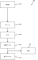
図1A及び図1Bは、電子デバイス112のエネルギーを収集するためのシステム100内のエネルギーの流れを示す概略図である。システム100は、電気エネルギー発生器102を含む。
FIGS. 1A and 1B are schematic diagrams showing energy flow within a
発生器102は、機械エネルギーを電気エネルギーに変換することが可能な任意のデバイスであり得る。発生器102は、回生ブレーキモータであり得、これは本質的に、逆方向(制動中)に動作するときにモータシャフトを回転させる抵抗を作り出すDCモータであり得、その逆回転は、モータ内で電力を発生させる。発生器102は、コイル及び磁石を含み得、そのうちの1つは、以下で更に説明するようにホイールハブ104、ホイール106、又はタイヤ108上に配向される。磁石に対して電気コイルを回転させるか、又は別様に移動させることにより、電流がコイル内に作り出され得、その電流は、電気デバイス又は電気貯蔵構成要素に方向付けられ得る。
発生器102は、ホイールハブ104に動作可能に接続され得る(図1Aを参照)。ホイールハブ104は、ハブユニット及びハブベアリングを含むアセンブリであり得、本明細書の参照を容易にするために、ホイールハブと総称される。
駆動ホイール用のホイールハブ104は、非駆動ホイールとは異なり得ることを理解されたい。すなわち、駆動ホイール用のホイールハブは、一方の端部でホイールにボルト留めし、他端の車軸の端部に取り付け、車軸とホイールとが1:1比で回転するように構成され得る。軸受は、ホイールハブ上に配向され、車両シャーシ上の保持ブラケットに接続され得、これは、ホイールをシャーシに固定して、ホイールをその所望の運動制約内に維持する。発生器102が回生ブレーキモータである場合、ホイールは駆動ホイールである可能性が高く、車軸は、モータシャフト(直接駆動システムの場合)、又は送信の出力シャフト(ギア駆動システムの場合)であり得る。
It should be appreciated that the
一方、非駆動ホイール用ホイールハブは、一方の側でホイールに取り付けられ得るが、駆動軸に取り付けられ得る。むしろ、ホイールハブは、ホイールの回転によって電気を発生させるように構成されている発生器に取り付けられ得るか、又は電気を発生させるデバイスに動作可能に接続され得る(例えば、ホイールハブは、車両シャーシ又はそれに隣接する本体上の静止位置に固定された対応する磁石又はコイルに対して回転するか、又は別様に移動するコイル若しくは磁石を含み得る)。非駆動ホイールの場合、ホイールハブ内の軸受は、上述のように、車両シャーシ上の保持ブラケットに接続され得る。 Wheel hubs for non-driven wheels, on the other hand, may be attached to the wheel on one side, but attached to the drive shaft. Rather, the wheel hub may be attached to a generator configured to generate electricity by rotation of the wheel, or may be operably connected to a device that generates electricity (e.g., the wheel hub may be attached to a vehicle chassis). or may include coils or magnets that rotate or otherwise move with respect to corresponding magnets or coils that are fixed in a stationary position on the body adjacent thereto). For non-driven wheels, bearings in the wheel hub may be connected to retaining brackets on the vehicle chassis, as described above.
代替的に、図1Bに示すように、互いに対して回転するか又は別様に移動する磁石を含む、コイル及び磁石を含む発生器は、ホイール106内に直接通過する電気を発生させるために、ホイール106に直接固定され得る。
Alternatively, as shown in FIG. 1B, a generator including coils and magnets, including magnets that rotate or otherwise move relative to each other, can be used to generate electricity that passes directly into the
図1A及び図1Bの両方において、システム100は、車両構成要素を通って電流の流れを方向付ける。すなわち、電気は、発生器102内で発生し、ハブ104に方向付けられ、次いでホイール106(図1A)内へ方向付けられる。代替的に、電気は、発生器102内で発生し、ハブ104を迂回して、ホイール106内に直接方向付けられる(図1B)。システム100のいずれかの変形例では、システム100に示される構成要素は、電気導電性であるか、又は電気導電性であるように修正されている。すなわち、ハブ104は、金属製であり、車両の車軸と車両のホイールとの境界面を介しており、ハブ104を介してホイール106に電気を通過させることができる。ホイール106は同様に金属製であり、したがって、電気は、ホイール106を通過してタイヤ108に入ることができる。タイヤは、典型的には、複数の材料から形成され、その材料の多くはゴムであり、多くの場合、電気絶縁性である。しかしながら、以下に更に記載されるように、タイヤ108は、タイヤ108を通る又はそれに沿った電流の通過を可能にするように修正することができる。発生器102から、最終的にはホイール106を通過して(ハブ104を通過するか又はハブ104の周りかにかかわらず)、及びタイヤ108の一部分を通るか又はそれに沿って通過した電流は、電気貯蔵デバイス110に方向付けられる。
In both FIGS. 1A and 1B,
電流の電気は、電気貯蔵デバイス110に貯蔵され得る。電気貯蔵デバイス110が、その電力容量を維持又は回復するための通常の電流源を有するため、デバイス110は、電気貯蔵デバイスに電流を供給しないシステムで利用される電気貯蔵デバイスよりも小さく、かつより軽くてもよいが、むしろ、電気貯蔵デバイスは、指定された車両メンテナンス間隔の間など、より長い期間、電力容量を維持することを必要とする。
The electricity of the current can be stored in the
貯蔵デバイス110は、放電されることが望まれるまで電気を貯蔵するように構成されている様々なデバイスのうちのいずれかであり得る。例えば、貯蔵デバイス110は、バッテリー、キャパシタなどであり得る。
貯蔵デバイス110は、電子デバイス112に電力を供給するために必要に応じて様々な電圧のいずれかで動作する電池であり得る。例えば、貯蔵デバイス110は、約3V~5Vの電圧を有する電池であり得る。貯蔵デバイス110は、電子デバイス112に電力を供給するために必要とされる様々な貯蔵容量のいずれかを有する電池であり得る。例えば、貯蔵デバイス110は、約100mAhの貯蔵容量を有する電池であり得る。
貯蔵デバイス110は、電子デバイス112に電気を提供し得る。電子デバイス112は、タイヤ108内で望ましい場合がある様々な電子デバイスのいずれかであり得る。例えば、電子機器112は、タイヤ圧力、タイヤ温度、タイヤ108内の異物の存在などの少なくとも1つを監視するためのセンサであり得る。電子デバイス112は、動作するための様々な電圧及び/又はワット数要件のいずれかを有し得る。例えば、電子デバイス112は、約数十ワットのワット数入力を必要とし得る。電子デバイス112は、100ワット未満のワット数入力を必要とし得る。電子デバイス112は、75ワット未満のワット数入力を必要とし得る。電子デバイス112は、50ワット未満のワット数入力を必要とし得る。電子デバイス112は、25ワット未満のワット数入力を必要とし得る。
貯蔵デバイス110を電気で充電する間、貯蔵デバイス110の貯蔵限界を超えるか、又は貯蔵デバイス110の充電速度を超えるかのいずれかの余分な電気が、タイヤ108から接地114へと方向付けられる。導電経路は、上述のように電気の流れを可能にするために、タイヤ108内に含まれるか、又は利用され得、以下で更に説明される。
During charging of
システム100は、発生器102から供給される電圧を電気貯蔵デバイス110内に貯蔵するための所望の電圧に低減する目的で、システム100内の1つ以上の抵抗器を含み得る。システム100は、発生器102から供給される電圧を電子デバイス112に電力供給する際に使用するための所望の電圧に低減する目的で、システム100内の1つ以上の抵抗器を含み得る。
図2A及び図2Bは、タイヤ208内の電子デバイスのためにエネルギーを収集するためのシステム200を示す。システム200は、ホイールハブ204、ホイール206、及びタイヤ208を含み得る。ホイール206は、複数のラグ穴207を含み得る。ラグ穴207は、ラグ穴207を通ってホイールハブ204とホイール206との間に延在するラグ(ねじ付き締結具、図示せず)を受け入れ得る。ラグは、ラグナット(図示せず)で固定されて、したがってホイール206をホイールハブ204に取り外し可能に固定し得る。電流がホイールハブ204からホイール206に通過する場合、電流は、ホイールハブ204とホイール206との間の直接的な物理的接触を介して、ホイールハブ204、ラグ、ラグ穴207、及びラグナットうちの少なくとも2つの間の物理的接触を介して、又はその両方を介して通過し得る。ホイールハブ204が、ホイール206に直接物理的に接触し得ることを理解されたい。しかしながら、ホイールハブ204及びホイール206の一方又は両方は、塗料又はシール剤でコーティングされ得、したがって、2つの間の接触は、電気の流れを可能にしない場合がある(コーティングが典型的には電気導電性ではなく、したがって2つの一方又は両方を電気的に絶縁するため)。したがって、ホイールハブ204及びホイール206は、互いに直接物理的に接触し得るが、この接触は、電気的接触を生じなくてもよく、電気接点は、コーティングされていない嵌合表面を含み得る、ラグとラグ穴207とラグナットとの間の物理的接触を介して行われてもよい。代替的に、ラグ穴207のうちの少なくとも1つは、以下により詳細に記載される1036、1136、1236、1336、1436、及び1536と同様の導電性領域を含む環状壁によって画定され得る。
2A and 2B show a
図2Aに示すように、タイヤ208は接地214に接触し得る。接地214は、タイヤ208が地面に接続されている任意の表面であり得、例えば、車道を含む。タイヤ208は、少なくとも接地面(タイヤが荷重下の表面上に載置されたときに作り出されるタイヤの平坦領域)内で接地214に接触することになる。したがって、以下で更に説明するように、タイヤ208内の接地経路は、タイヤ208の接地面に配向されたタイヤのトレッドの一部分に配向されることになる。
As shown in FIG. 2A,
図3は、タイヤ308内の電子デバイスのためにエネルギーを収集するためのシステム300を示す。システム300は、電動モータ駆動車軸316の形態の発生器302を含み得る。電気モータは、直流モータであり得、これは、制動中に逆に動作すると、発生器として機能する。車軸316は、ホイールハブ304に接続し得る。ホイールハブ304は、タイヤ308が装着されるホイール306に接続されている。車軸316、ハブ304、及びホイール306は、金属製及び電気導電性である。したがって、発生器302によって発生した電気は、車軸316に供給され、ハブ304を通ってホイール306内へと伝わり得る。ホイール306から、電気は、タイヤ308内の導電性要素及び/又は導電性金属ベルトを通って、タイヤ308内に配向された電気貯蔵デバイス及び/又は電子デバイスへと伝わり得る。したがって、導電経路は、発生器302から、タイヤ308内に収容された電気貯蔵デバイス及び/又は電子デバイスまでに存在する。発生器302、車軸316、ホイールハブ304、及びホイール306は、車両又は接地の他の構成要素から電気的に絶縁され得る。タイヤ308は、接地に電気的に接続され得、そうでなければ、ホイール306へのタイヤ308の電気的接続を除いて電気的に絶縁され得る。このようにして、電気回路は、発生器302から接地(例えば、114、214)への前述の構成要素を介して作り出され、したがって電流が回路を通過することを可能にする。
FIG. 3 shows a
図4は、タイヤ408内の電子デバイスのためにエネルギーを収集するためのシステム400の断面図を示す。システムは、タイヤ408が装着されるホイール406を含み、ホイール406は、車軸416に動作可能に接続されている。発生器418は、ホイール406に動作可能に接続され得る。発生器418は、ホイール406に回転可能に接続され得る。発生器418は、発生器418の回転、ホイール406の回転、又は互いに対する両方の回転によって電気を発生させ得る。例えば、発生器418は、ホイール406が回転すると偏心質量が回転するように、偏心質量を装着された中心軸(図示せず)を有し得る。発生器418は、中心軸、偏心質量、又はホイール406に取り付けられた磁石又はコイルを含み得、これによって、コイル及び磁石の一方が偏心質量と共に回転する一方で、コイル及び磁石の他方は偏心質量と共に回転しない。結果は、発生器418内での電気の発生であり得る。この電気は、以下で更に説明するように、ホイール406を介してタイヤ408に供給されて、電気貯蔵デバイス及び電気デバイスに電力を供給し得る。
FIG. 4 shows a cross-sectional view of
図5は、タイヤ508内の電子デバイスのためにエネルギーを収集するためのシステム500の断面図を示す。システムは、タイヤ508が装着されるホイール506を含み、ホイール506は、車軸516に動作可能に接続されている。
FIG. 5 shows a cross-sectional view of
発生器520は、ホイールハブ504を介してホイール506に動作可能に接続され得る。発生器520は、ホイール506が回転する間に発生器520が回転しないように、ホイール506から回転可能に絶縁され得る。発生器520は、コイルを含み得る。
磁石522は、ホイール506に接続され、発生器520の周りでホイール506と共に回転することにより、発生器520内に収容されたコイルを通して電流を発生させ得る。この電気は、以下で更に説明するように、ホイールハブ504を介してホイール506に及びタイヤ508内に供給されて、電気貯蔵デバイス及び電気デバイスに電力を供給することができる。
A
図6は、タイヤ608内の電子デバイスのためにエネルギーを収集するためのシステム600の断面図を示す。システムは、タイヤ608が装着されるホイール606を含み、ホイール606は、ホイールハブ604を介して車軸616に動作可能に接続されている。
FIG. 6 shows a cross-sectional view of
発生器624は、ホイールハブ604の車軸616の係合を介してホイール606に動作可能に接続され得る。発生器624は、回生ブレーキ中に逆に動作するときに電流を作り出す、DC電気モータであり得る。この電気は、以下で更に説明するように、軸616を介してホイールハブ604に、ホイール606に及びタイヤ608内に供給されて、電気貯蔵デバイス及び電気デバイスに電力を供給し得る。
図7は、タイヤ708内の電子デバイスのためにエネルギーを収集するためのシステム700の断面図を示す。システムは、タイヤ708が装着されるホイール706を含み、ホイール706は、ホイールハブ704を介して車軸716に動作可能に接続されている。
FIG. 7 shows a cross-sectional view of
発生器(図示せず)は、車軸716を介してホイール706に動作可能に接続され得る。発生器は、回生ブレーキ中に逆に動作するときに電流を作り出す、DC電気モータであり得る。この電気は、ブラシ730を介してホイール706の電流受容要素728に電気的に接続されている電流送出要素726に供給され得る。電流送出要素726は、車両上の車体、シャーシ、又は別様に静止した非回転物体に接続され得る。電流受容要素728は、ホイール706の一体の環状の隆起部であり得る。電流受容要素728は、ホイール706に物理的、電気的、又はその両方に接続された環であり得る。電流送出要素726及び電流受容要素728の両方は、電気導電性である。ブラシ730は、電気導電性である。ブラシ730は、電流送出要素726に接続され得、電流受容要素728の表面に沿ってスライド、ロール、又は別様に並進し得る。
A generator (not shown) may be operably connected to
電流受容要素728がホイール706に接続されていると、電流受容要素728はホイール706と共に回転する。電流送出要素726は、静止し得、車両シャーシに取り付けられ得る。したがって、電流受容要素728は、電流送出要素726に対して回転し、ブラシ730は、一方が他方に対して回転したときでも、これらの要素間の電気導電性接続を提供する。
When current receiving
したがって、電気は、以下で更に説明するように、電流送出要素726を通じて、ブラシ730を通って電流受容要素728に、ホイール706に、及びタイヤ708内に供給されて、電力貯蔵デバイス及び電気デバイスに電力を供給することができる。
Thus, electricity is supplied through current sending
図8は、タイヤ808内の電子デバイスのためにエネルギーを収集するためのシステム800の断面図を示す。システムは、タイヤ808が装着されるホイール806を含み、ホイール806は、ホイールハブ804を介して車軸816に動作可能に接続されている。
FIG. 8 shows a cross-sectional view of a
発生器(図示せず)は、車軸816を介してホイール806に動作可能に接続され得る。発生器は、回生ブレーキ中に逆に動作するときに電流を作り出す、DC電気モータであり得る。この電気は、ブラシ830を介してホイール806の電流受容要素828に電気的に接続されている電流送出要素826に供給され得る。電流送出要素826は、ホイールハブ804に接続され得、ホイール806及び電流受容要素828に対して回転的に静止し得る。電流受容要素828は、ホイール806の一体の環状の隆起部であり得る。電流受容要素828は、ホイール806に物理的、電気的、又はその両方に接続され得る。電流送出要素826及び電流受容要素828の両方は、電気導電性である。ブラシ830は、電気導電性である。ブラシ830は、電流送出要素826に接続され得、電流受容要素828の表面に沿ってスライド、ロール、又は別様に並進し得る。代替的に、ブラシ830は、電流受容要素828に接続され得、電流送出要素826の表面に沿ってスライド、ロール、又は別様に並進し得る。
A generator (not shown) may be operably connected to
電流受容要素828がホイール806に接続されていると、電流受容要素828はホイール806と共に回転する。電流送出要素826は、静止し得、ホイールハブ804に取り付けられ得る。したがって、電流受容要素828は、電流送出要素826に対して回転し、ブラシ830は、一方が他方に対して回転したときでも、これらの要素間の電気導電性接続を提供する。
When current receiving
したがって、電気は、以下で更に説明するように、電流送出要素826を通じて、ブラシ830を通って電流受容要素828に、ホイール806に、及びタイヤ808内に供給されて、電力貯蔵デバイス及び電気デバイスに電力を供給することができる。
Thus, electricity is supplied through current sending
図9は、バレル932の軸方向外側縁部上に一対のリムリップ934を有するホイール906を示す。ホイール906は、例えば、アルミニウム又は鋼などの電気導電性材料から作製され得る。加えて、ホイール906は、クロムメッキなどの電気導電性材料でコーティングされ得る。ホイール906が、コーティングされていない電気導電性材料から作製されるか、又は電気導電性材料でコーティングされる場合、ホイール906は、上述のように、ハブ、車軸から、又は発生器から直接電流を伝達し得る。この電流は、以下に更に記載されるように、導電性要素及び/又は導電性金属ベルトを通じてタイヤに導電され得る。
FIG. 9 shows wheel 906 having a pair of
図10は、バレル1032の軸方向外側縁部上に一対のリムリップ1034を有するホイール1006を示す。リムリップ1034のうちの少なくとも1つは、導電性領域1036を含む。
FIG. 10 shows wheel 1006 having a pair of
多くの場合、ホイール1006などのホイールは、非導電性の塗料又は他のコーティングでコーティングされ得る。これらのコーティングは、主として、ホイール1006を保存し、それを要素から保護して、腐食及び/又は酸化を回避し、ホイールの洗浄を単純化することなどを目的とする。そのような場合、コーティングがホイール1006を電気的に絶縁することができるので、電気は、ホイール906ほどにはホイール1006に容易には通過できない場合がある。
In many cases, wheels such as
典型的には、ホイール1006を車両上に装着するプロセスは、ホイール1006のホイールハブからラグ穴(上述のラグ穴207など)の中にラグを挿入し、その後ラグナットをラグに適用し、その時点でホイールハブからホイール1006内に電流を通過させるのに十分な程度にラグ穴の領域内のコーティングをこすり、スクラッチし、かつ除去することを含む。これは、ホイール1006をホイールハブにボルト留めすることに関与する高圧メタルオンメタル接触によるものである。しかしながら、タイヤをホイール1006に装着する際に、タイヤは、電気コーティングがホイール1006からその時点でタイヤに通過するのを可能にするのに十分な程度にリップリップ1034からコーティングをこするか又はスクラッチすることはない。
Typically, the process of mounting
タイヤをホイール1006に装着するとき、タイヤのビード、より具体的には、ビードシート及びビードヒールは、リムリップ1034と係合する。タイヤの膨張圧力は、ビードを軸方向外向きに駆動してリムリップ1034と接触させる一方で、タイヤビード内のビードワイヤはビードの直径を制限し、タイヤをリムリップ1034に対して緊密にフィットさせる。
When the tire is mounted on
タイヤのビードシート及び/又はビードヒール領域内に配向された導電要素が、ホイール1006のコーティングされていない部分と電気的に接触することが可能であることを確実にするために、少なくとも1つのリムリップ1034は、部分的に周方向又は完全に周方向の導電性領域1036を含み得る。導電性領域1036は、ホイール1006の非導電性コーティングがリムリップ1034から除去された領域であり得る。任意選択的に、導電性コーティングは、ホイール1006内の耐食性及び耐酸化性を補助するために、非導電性コーティングが除去されたリムリップ1034の一部分の上に配置され得る。導電性コーティングは、金属フレーク又は炭素要素などの導電性要素の導入によって導電性が増大した塗料又はグリースを含み得る。
At least one
ホイール1006は、以下に更に記載されるタイヤ2100の導電性要素2142など、タイヤ上の単一の点で周方向に配向された導電性要素を有するタイヤと共に使用され得る。導電性領域1036がホイール1006の周りで完全に周方向である場合、導電性要素2142が角度位置合わせにかかわらず導電性領域1036と接触するため、ホイール1006に対するタイヤの角度位置合わせは重要ではない。
導電性領域1036がホイール1006の周りで部分的に周方向である場合、導電性要素2142が、特定の角度位置合わせでのみ、又は部分的に周方向の導電性領域1036の周方向長さに対応する角度位置合わせの範囲内でのみ導電性領域1036に接触することになるので、ホイール1006に対するタイヤの角度位置合わせは適切に配向されなければならない。そのような実施形態では、タイヤ2100及びホイール1006は、ホイール1006上の個々の設置タイヤ2100によって識別され得るマーキング又は他のインジケータを有して、ホイール1006上のタイヤ2100の適切な角度位置合わせを容易にして、導電性領域1036と導電性要素2142との間の接触を確実にし得る。
If the
同様に、ホイール1006がリムリップ1034のうちの1つの上に導電性領域1036のみを含む場合、ホイール1006は、ホイール1006上にマーキング又は他のインジケータを含むことにより、ホイール1006にタイヤを個々に設置して、どのリムリップ1034が導電性領域1036を含むかを判定し得る。タイヤ2100などのタイヤは、タイヤ2100の一方の側のみに導電性要素2142を含み得、したがって、ホイール上の個々の設置タイヤ2100が、タイヤ及びホイールの導電性側と一致することを可能にして、導電性要素と導電性領域との間の接触を確保する、類似のマーキング又はインジケータを含み得、その結果、導電経路が形成される。
Similarly, if the
ホイール1006は、以下に更に説明するタイヤ2200の導電性要素2242など、タイヤの周囲で完全に周方向に配向された導電性要素を有するタイヤと共に使用され得る。すなわち、導電性領域1036が部分的又は完全に周方向であるかどうかにかかわらず、導電要素2242及び導電性領域1036がタイヤ及びホイール組立体の同じ側に配向されていると仮定して、導電性要素2242は、角度整合にかかわらず導電性領域と接触することになる。タイヤ2200及びホイール1006は、タイヤ2200及びホイール1006のいずれかの側(1つのみ)が導電性特徴部を含むことにより、ホイール上にタイヤを設置する個人がその適切な配向を確実にし得るように、導電性特徴部を含むことを示すためのマーキング又は他のインジケータを含み得る。
図11は、少なくとも1つが少なくとも1つの導電性領域1136を含む、一対のリムリップ1134を有するホイール1106を示す。導電性領域1136は、ホイール1006の導電性領域1036と同様であり得、同じ方法で使用及び形成され得る。具体的には、導電性領域1136は、非導電性絶縁コーティング又は塗料が除去されたリムリップ1134の領域であり得る。
FIG. 11 shows a
導電性領域1136は、リムリップ1134上の単一の周点に配向され得る。導電性領域1136は、リムリップ1134上の複数の周点に配向され得る。
ホイール1106は、以下に更に記載されるタイヤ2100の導電性要素2142など、タイヤ上の単一の点で周方向に配向された導電性要素を有するタイヤと共に使用され得る。この使用では、導電性要素2142が、特定の角度位置合わせでのみ、又は部分的に周方向の導電性領域1136の周方向長さに対応する角度位置合わせの範囲内でのみ導電性領域1136に接触することになるので、ホイール1106に対するタイヤの角度位置合わせは適切に配向されなければならない。そのような実施形態では、タイヤ2100及びホイール1106は、ホイール1106上の個々の設置タイヤ2100によって識別され得るマーキング又は他のインジケータを有して、ホイール1106上のタイヤ2100の適切な角度位置合わせを容易にして、導電性領域1136と導電性要素2142との間の接触を確実にし得る。
同様に、ホイール1106がリムリップ1134のうちの1つの上に導電性領域1136のみを含む場合、ホイール1106は、ホイール1106上にマーキング又は他のインジケータを含むことにより、ホイール1106にタイヤを個々に設置して、どのリムリップ1134が導電性領域1136を含むかを判定し得る。タイヤ2100などのタイヤは、タイヤ2100の一方の側のみに導電性要素2142を含み得、したがって、ホイール上の個々の設置タイヤ2100が、タイヤ及びホイールの導電性側と一致することを可能にして、導電性要素と導電性領域との間の接触を確保する、類似のマーキング又はインジケータを含み得、その結果、導電経路が形成される。
Similarly, if the
ホイール1106は、以下に更に説明するタイヤ2200の導電性要素2242など、タイヤの周囲で完全に周方向に配向された導電性要素を有するタイヤと共に使用され得る。導電性要素2242及び導電性領域1136が、タイヤ及びホイール組立体の同じ側に配向されていると仮定して、完全に周方向の導電性要素2242は、角度位置合わせにかかわらず導電性領域1136と接触することになる。タイヤ2200及びホイール1106は、タイヤ2200及びホイール1106のいずれかの側(1つのみ)が導電性特徴部を含むことにより、ホイール上にタイヤを設置する個人がその適切な配向を確実にし得るように、導電性特徴部を含むことを示すためのマーキング又は他のインジケータを含み得る。
図12は、少なくとも1つが少なくとも1つの導電性領域1236を含む、一対のリムリップ1234を有するホイール1206を示す。導電性領域1236は、ホイール1006の導電性領域1036と同様であり得、同じ方法で使用及び形成され得る。具体的には、導電性領域1236は、非導電性絶縁コーティング又は塗料が除去されたリムリップ1234の領域であり得る。非導電性コーティング又は塗料の除去部位における腐食又は酸化を回避又は緩和するために、導電性コーティング1238を導電性領域1236の上にキャップとして配置することができる。導電性コーティング1238は、導電性領域1236を完全に覆い、要素、水分、空気などから導電性領域1236を封止するように作用し得、腐食又は酸化を引き起こし得る。導電性コーティング1238は、金属フレーク又は炭素要素などの導電性要素の導入によって導電性が増大した塗料又はグリースを含み得る。
FIG. 12 shows a
図13は、導電性カバー1338によって封止された導電性領域1336を示す。図12に関して説明したように、導電性領域1336は、非導電性絶縁コーティング又は塗料が除去された場所であり得る。導電性カバー1338は、導電性領域1336をキャップし、導電性領域1336を要素、水分、空気などから封止し、腐食又は酸化を引き起こし得る。導電性コーティング1338は、金属フレーク又は炭素要素などの導電性要素の導入によって導電性が増大した塗料又はグリースを含み得る。
FIG. 13 shows a
図14は、非導電性カバー1440及びそれらの間に配向された導体1441によって封止された導電性領域1436を示す。導電性領域1436は、上記に記載する導電性領域1136、1236、及び1336と実質的に同様のものであってもよい。
FIG. 14 shows a
非導電性カバー1440は、導電性領域1436をキャップし、かつ導電性領域1436を要素、水分、空気などから封止するように作用する様々な材料のうちのいずれかであり得、これは腐食又は酸化を引き起こし得る。
The
導体1441は、遠位側ホイール接触端部1441A、及び近位側タイヤ接触端部1441Bを含み得る。ホイール接触端部1441Aは、ホイールと非導電性カバー1440との間に挟まれた導電性領域1436と物理的及び/又は電気的接触して配向され得る。タイヤ接地端部1441Bは、ホイールと非導電性カバー1440との結合体の外側に延在し、非導電性カバー1440の上に折り返され得る導体1441の一部分であり得る。このようにして、タイヤ接地端部1441Bは、非導電性カバー1440の外側に延在し、タイヤ(図示せず)と物理的及び/又は電気的接触して配向され得る。導体1441は、ホイール接触端部1441A及びタイヤ接触端部1441Bが互いに電気的に接続されているように、連続的な電気導電性要素であることを理解されたい。導体1441は、電気導電性特性を含む材料の金属ストリップであり得る。
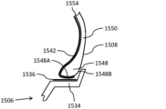
図15は、ホイール1506のリムリップ1534に係合するタイヤ1508を示す。ホイール1506は、少なくとも1つの導電性領域1536を有する少なくとも1つのリムリップ1534を含み得る。
FIG. 15 shows tire 1508 engaging
タイヤ1508は、ビードシート1548A及びビードヒール1548Bを含むビード部1548を含む。図示されるように、ビードシート1548Aは、ビード部1548の半径方向内側部分に配向され、ビードヒール1548Bは、ビード部1548の軸方向外側部分に配向される。ビードシート1548A及びビードヒール1548Bは、タイヤ1508とホイール1506との間の一次接触点である(これらの要素は、要素間の配向及び差別化をより容易に示すために小さい間隙で例示されているが、実際には、これらの要素は互いに強固に接続され、大きな圧力の程度である可能性が高くなるであろうことに留意されたい)。
タイヤ1508は、ビードシート1548A及びビードヒール1548Bのうちの少なくとも1つから、タイヤサイドウォール1550の内面1554の少なくとも一部分に沿って延在する導電性要素1542を含む。タイヤ1508の1つの側のみ、及び1つのビード部1548のみが示されている一方で、タイヤ1508が、2つのビード部1548を有し、両方のビードシート1548A及び両方のビードヒール1548Bのうちの少なくとも1つを含む両方のビード部1548が、記載されるように導電性要素1542を含み得ることが理解される。
導電性要素1542は、例えば、金属、又は高炭素含有量を有するポリマー若しくはゴムを含む、電気を導電することが可能な様々な材料のうちのいずれかから作製され得る。導電性要素1542は、電流を搬送することが可能な電気ワイヤを使用し得る。導電性要素1542は、タイヤ技術において一般に「アンテナ」と称される導電性ゴム材料を使用し得る。
導電性要素1542は、タイヤ1508に一体的に組み込まれ得る。導電性要素1542は、接着剤又は他の締結機構を介して内面1554と積層され得る。
一態様では、導電性要素1542は、タイヤから静電気を含む電気を通過させるためにタイヤのトレッドに使用される「アンテナ」材料と同様又は同じ導電性ゴム材料からなる導電経路である。一態様では、アンテナは、タイヤ1508の内側に配向され、内面1554の軸方向内側及び/又は半径方向内側に配向される。代替的に、アンテナは、タイヤ1508の層の間(例えば、以下で説明する図23に示され得るように、インナーライナプライの間)に配向される。
In one aspect, the
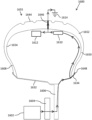
図16は、タイヤ1608内の電子デバイス1612のエネルギーを収集するためのシステム1600の断面概略を示す。電流の流れは、矢印を含む線を介して例示される。システム1600は、ホイール1606に電気的に接続され得るホイールハブ1604に電気的に接続されている発生器1602を含み得る。
FIG. 16 shows a cross-sectional schematic of a
タイヤ1608は、ホイール1606に装着され得、ホイール1606に電気的に接続され得る。ホイール1606の少なくとも1つのリムリップ1634と少なくとも1つのビード部1648との間の接触は、電気がホイール1606からタイヤ1608へと通過することを可能にし得る。電気は、概して、少なくとも1つのビード部1648の領域から、少なくとも1つのサイドウォール1650まで、少なくとも1つの肩部1652まで、かつトレッド1644の領域全般の中へ通過し得る。
ホイール1606とのタイヤ1608の係合によって作り出され、タイヤ1608の内面1654及びホイール1606のバレル1632によって境界される、チャンバ内の任意の点において配向され、少なくとも1つの電気貯蔵デバイス1610、及び少なくとも1つの電子デバイス1612において配向され得る。
oriented at any point within the chamber created by engagement of
電気貯蔵デバイス1610及び電子デバイス1612の一方又は両方は、トレッド1644を含むトレッド領域1655と称されるタイヤ1608の領域内の内面1654に接続され得る。
One or both of
電気貯蔵デバイス1610及び電子デバイス1612の一方又は両方は、電気貯蔵デバイス1610及び電子デバイス1612の一方又は両方が、インナーライナとボディプライとの間、ボディプライとベルトとの間、ベルトとトレッドゲージとの間などに収容されるように、トレッド1644の内面1654の半径方向外側及び半径方向内側に配向され得る。すなわち、電気貯蔵デバイス1610及び電子デバイス1612の一方又は両方は、ホイール1606とのタイヤ1608の係合によって作り出され、タイヤ1608の内面1654及びホイール1606のバレル1632によって境界される、チャンバ内ではなく、トレッド領域1655内のタイヤ1608の厚さ内に収容され得る。
One or both of the
電気貯蔵デバイス1610及び電子デバイス1612の一方又は両方は、タイヤ1608の製造中にタイヤ1608を構成し得る材料の連続層のいずれかの間に埋め込まれ得、そのような層としては、インナーライナ、ボディプライ、ビードフィラー、ガムストリップ、肩部インサート、ベルト、キャッププライ、トレッド、及びサイドウォールプライが挙げられるが、これらに限定されない。タイヤ構造は大きく変化することができ、上記のリストは、タイヤ内のあらゆる可能な材料層の網羅的でも包括的であることを意図するものではないことが理解される。
One or both of the
電気貯蔵デバイス1610から1つ以上の電子デバイス1612に電力を供給するのに必要な電気を超過する電気は、トレッド1644内の接地経路1646を通って接地1614に通過し得る。本明細書に記載される導電性要素のような接地経路1646は、アンテナを含む電気を導電することが可能な任意の様々な材料であり得る。一態様では、接地経路1646はアンテナである。動作中、タイヤ1608のトレッド1644は、接地1614に接触し、接地経路1646は、同様に接地1614に接触して、接地1614への電気の伝送を可能にする。接地経路1646は、トレッド領域1655内のタイヤ1608の厚さ全体を通って、内面1654からトレッド1644の接地面までタイヤ1608の外面上に延在し得る。
Electricity in excess of that required to power one or more
このようにして、導電経路は、接地1614に伝達される電子デバイス1612に電力を供給するのに必要なものを超過する電気エネルギーを伴って、電気貯蔵デバイス1610及び電子デバイス1612に至るまで、発生器1602から作り出され得る。この超過エネルギーを接地1614に通過させる能力により、タイヤ1608が装着された車両が接地されるような方法でタイヤ1608が機能し続けることができ、それによって、車内の電気エネルギーの蓄積(これは、車両の使用者に危険又は不快感をもたらし得る、スパーク、電撃、又は他の不要な変化を生じ得る)を防止する。システム1600は、そうでなければ接地1614に直接伝達される電気エネルギーの一部分を利用して、少なくとも1つの電気貯蔵デバイス1610に貯蔵され、少なくとも1つの電子デバイス1612に電力を供給する。システム1600は、発生器1602から少なくとも1つの電気貯蔵デバイス1610へと電気を流し、かつ少なくとも1つの電子デバイス1612に電力を供給することを可能にする回路を作り出す。
In this manner, a conductive path is developed to
図17は、タイヤ1708内の電子デバイスのためにエネルギーを収集するためのシステム1700の断面図を示す。システム1700は、ホイールハブ1704、ホイール1706、及びタイヤ1708を含む。ホイール1706は、タイヤ1708のビード部1748に接触する一対のリムリップ1734を含む。
FIG. 17 shows a cross-sectional view of
タイヤ1708は、一対のビード部1748、一対のサイドウォール1750、一対の肩部1752、及びトレッド1744を含む。タイヤ1708は、内面1754を含み得る。
システム1700は、上述のように、発生器から少なくとも1つの電気貯蔵デバイス及び少なくとも1つの電子デバイスへの電気の伝送を可能にするためにシステム1600に含まれるものなどの追加の構成要素を含み得る。
図18は、タイヤ1808の断面図を示す。タイヤ1608及び1708と同様に、タイヤ1808は、一対のビード部1848、一対のサイドウォール1850、一対の肩部1852、トレッド1844、及び内面1854を含む。タイヤ1808は、少なくとも1つのビード部1848から始まり、かつ1つ以上の電気貯蔵デバイスと電気的に接触する位置までタイヤ1808内に延在する、導電性要素1842を含む。
FIG. 18 shows a cross-sectional view of
図19は、タイヤ1908の内面1954に適用された導電性要素1942を有するタイヤ1908の断面図を示す。タイヤ1908は、一対のビード部1948、一対のサイドウォール1950、一対の肩部1952、及びトレッド領域1955内に位置するトレッド1944を含む。
FIG. 19 shows a cross-sectional view of
各ビード部1948は、ビードシート1948A及びビードヒール1948Bを含み得る。少なくとも1つの導電性要素1942は、少なくとも1つの肩部1952に沿って少なくとも1つのサイドウォール1950に沿って少なくとも1つのビード部1948から延在し、トレッド領域1955で終端し得る。少なくとも1つの導電性要素1942は、内面1954と接触して配向される。
Each
一実施形態では、少なくとも1つの導電性要素1942は、内面1954に沿ってビードシート1948Aから延在し、トレッド領域1955で終端する。別の実施形態では、少なくとも1つの導電性要素1942は、内面1954に沿ってビードヒール1948Bから延在し、トレッド領域1955で終端する。
In one embodiment, at least one
内面1954は、インナーライナであり得、ブチルゴム化合物を含み得る。内面1954は、ボディプライであってもよい。内面1954は、内面1954から半径方向内側に配向され得る少なくとも1つの導電性要素1942を除いて、タイヤ1908の半径方向最内表面であり得る。
The
図20は、タイヤ2008内の電子デバイス2012のためにエネルギーを収集するためのシステム2000の断面図を示す。
FIG. 20 shows a cross-sectional view of
タイヤ2008は、一対のビード部2048、一対のサイドウォール2050、一対の肩部2052、及びトレッド領域2055内に位置するトレッド2044を含む。タイヤ2008は、内面2054を含み得る。
各ビード部2048は、ビードシート2048A及びビードヒール2048Bを含む。1つ以上の導電性要素2042は、1つの又は各肩部2052に沿って1つの又は各サイドウォール2050に沿って1つの又は各ビード部2048からトレッド領域2055内に延在し得る。1つ以上の導電性要素2042は、内面2054上に配向される。1つ以上の導電性要素2042の各々は、各ビードシート2048Aを起点とし得る。1つ以上の導電性要素2042の各々は、1つの又は各ビードヒール2048Bを起点とし、1つの又は各ビードシート2048Aに沿って、かつ1つの又は各サイドウォール2050に沿ってなど、又はトレッド領域2055に到達するまで延在し得る。
Each
システム2000は、少なくとも1つの電気貯蔵デバイス2010及び少なくとも1つの電子デバイス2012を含み得る。少なくとも1つの導電性要素2042は、少なくとも1つの電気貯蔵デバイス2010に電気的に接続されている。少なくとも1つの電気貯蔵デバイス2010は、少なくとも1つの電子デバイス2012に電気的に接続されている。
電気貯蔵デバイス2010から1つ以上の電子デバイス2012に電力を供給するのに必要な電気を超過する電気は、トレッド2044内の接地経路2046を通って接地に通過し得る。本明細書に記載される導電性要素のような接地経路2046は、アンテナを含む電気を導電することが可能な任意の様々な材料であり得る。一態様では、接地経路2046はアンテナである。接地は、地面、路面、又はタイヤ2008が動作し、かつ地面に接続している任意の表面であり得る。動作中、タイヤ2008のトレッド2044は、接地に接触し、接地経路2046は、同様に接地に接触して、接地への電気の伝送を可能にする。接地経路2046は、トレッド領域2055内のタイヤ2008の厚さ全体を通って、内面2054からトレッド2044の接地面までタイヤ2008の外面上に延在し得る。
Electricity in excess of that required to power one or more
図示されるように、少なくとも1つの電気貯蔵デバイス2010は、少なくとも1つの電子デバイス2012内に収容され得る。電気貯蔵デバイス2010及び電子デバイス2012の一方又は両方は、内面2054上に配向され得る。代替的に、電気貯蔵デバイス2010及び電子デバイス2012の一方又は両方は、タイヤ2008の製造中にタイヤ2008を構成し得る材料の連続層のいずれかの間に埋め込まれ得、そのような層としては、インナーライナ、ボディプライ、ビードフィラー、ガムストリップ、肩部インサート、ベルト、キャッププライ、トレッド、及びサイドウォールプライが挙げられるが、これらに限定されない。タイヤ構造は大きく変化することができ、上記のリストは、タイヤ内のあらゆる可能な材料層の網羅的でも包括的であることを意図するものではないことが理解される。
As shown, at least one
図21は、タイヤ2108内の電子デバイス2112のためにエネルギーを収集するためのシステム2100を示す。
FIG. 21 shows a
タイヤ2108は、一対のビード部2148、一対のサイドウォール2150、一対の肩部2152、及びトレッド2144を含む。
少なくとも1つの導電性要素2142は、少なくとも1つの肩部2152に沿って少なくとも1つのサイドウォール2150に沿って少なくとも1つのビード部2148から、トレッド2144が配向されるトレッド領域内に延在する。少なくとも1つの導電性要素2142は、少なくとも1つの電子デバイス2112に電気的に接続されている。少なくとも1つの電子デバイス2112は、少なくとも1つの電気貯蔵デバイス及び接地経路2146に電気的に接続され得る。接地経路2146は、接地に電気経路を提供するためにトレッド2144を通って延在する。動作中、タイヤ2108のトレッド2144は、接地に接触し、接地経路2146は、同様に接地に接触して、接地への電気の伝送を可能にする。接地経路2146は、トレッド領域2155内のタイヤ2108の厚さ全体を通って、内面2154からトレッド2144の接地面までタイヤ2108の外面上に延在し得る。
At least one
導電性要素2142は、タイヤ2108内の特定の周方向位置に配向され得る。導電性要素2142は、周方向に短い長さであり得る。導電性要素2142は、ワイヤ、又はアンテナなどの他の導電性材料を含み得る。
電子デバイス2112は、タイヤ2108の内面上に配向され得る。代替的に、電子デバイス2112は、タイヤ2108の製造中にタイヤ2108を構成し得る材料の連続層のいずれかの間に埋め込まれ得、そのような層としては、インナーライナ、ボディプライ、ビードフィラー、ガムストリップ、肩部インサート、ベルト、キャッププライ、トレッド、及びサイドウォールプライが挙げられるが、これらに限定されない。タイヤ構造は大きく変化することができ、上記のリストは、タイヤ内のあらゆる可能な材料層の網羅的でも包括的であることを意図するものではないことが理解される。
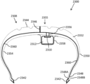
図22は、タイヤ2208内の電子デバイス2212のためにエネルギーを収集するためのシステム2200の立面図を示す。
FIG. 22 shows an elevational view of
タイヤ2208は、一対のビード部2248、一対のサイドウォール2250、一対の肩部2252、及びトレッド2244を含む。
少なくとも1つの導電性要素2242は、少なくとも1つの肩部2252に沿って少なくとも1つのサイドウォール2250に沿って少なくとも1つのビード部2248から、トレッド2244が配向されるトレッド領域内に延在する。少なくとも1つの導電性要素2242は、少なくとも1つの電子デバイス2212に電気的に接続されている。少なくとも1つの電子デバイス2212は、少なくとも1つの電気貯蔵デバイス及び接地経路2246に電気的に接続され得る。接地経路2246は、接地に電気経路を提供するためにトレッド2244を通って延在する。動作中、タイヤ2208のトレッド2244は、接地に接触し、接地経路2246は、同様に接地に接触して、接地への電気の伝送を可能にする。接地経路2246は、トレッド領域2255内のタイヤ2208の厚さ全体を通って、内面2254からトレッド2244の接地面までタイヤ2208の外面上に延在し得る。
At least one
導電性要素2242は、タイヤ2208内で完全に周方向に配向され得る。導電性要素2242は、タイヤ2208の周方向全長に沿って延在し得る。導電性要素2242は、ワイヤメッシュ、又はアンテナのシートなどの他の導電性材料を含み得る。
電子デバイス2212は、タイヤ2208の内面上に配向され得る。代替的に、電子デバイス2212は、タイヤ2208の製造中にタイヤ2208を構成し得る材料の連続層のいずれかの間に埋め込まれ得、そのような層としては、インナーライナ、ボディプライ、ビードフィラー、ガムストリップ、肩部インサート、ベルト、キャッププライ、トレッド、及びサイドウォールプライが挙げられるが、これらに限定されない。タイヤ構造は大きく変化することができ、上記のリストは、タイヤ内のあらゆる可能な材料層の網羅的でも包括的であることを意図するものではないことが理解される。
図23は、タイヤ2308内の電子デバイス2312のためにエネルギーを収集するためのシステム2300の断面図を示す。
FIG. 23 shows a cross-sectional view of
タイヤ2308は、一対のビード部2348、一対のサイドウォール2350、一対の肩部2352、及びトレッド領域2355内に位置するトレッド2344を含む。タイヤ2308は、内面2354を含み得る。タイヤ2308は、サイドウォール2350のうちの少なくとも1つに配向され得る少なくとも1つの金属コード2360を含み得る。
各ビード部2348は、ビードシート2348A及びビードヒール2348Bを含む。1つ以上の導電性要素2342は、1つの又は各ビード部2348の少なくとも一部に沿って延在し得る。1つ以上の導電性要素2342は、ビードシート2348Aを起点とし得る。1つ以上の導電性要素2342は、ビードヒール2348Bを起点とし得る。ビード部2348において若しくはその付近で、又はサイドウォール2350において若しくはその付近で、又は肩部2352において若しくはその付近で、導電性要素2342は、内面2354を貫通して、タイヤ2308の内部に延在する(内部は、サイドウォール2350、肩部2352、及びトレッド領域2355の厚さ内、並びにこれらの要素の内面と外面との間に画定される)。導電性要素2342は、タイヤ2308の内部に貫通し、金属コード2360に電気的に接続され得る。
Each
金属コード2360は、ある特定のタイヤのボディプライに使用され得る。例えば、高荷重用に設計されたタイヤであって、例えば、一部のオフロードタイヤ、トラック及びバスラジアルタイヤの一部又は全て、並びにいくつかの農業用タイヤは、タイヤ2308のボディプライ内に金属コード2360を含み得る。
金属コード2360は、電気導電性であり得、導電性要素2342から電気を電気貯蔵デバイス2310及び電子デバイス2312のうちの少なくとも1つに搬送することが可能であり得る。電気は、導電ブリッジ2356によって電気貯蔵デバイス2310及び電子デバイス2312のうちの少なくとも1つに、金属コード2360から電気を通過させ得る。導電ブリッジ2356は、タイヤ2308の内面2354を通過し、金属コード2360に電気的に接続され得る。導電ブリッジ2356は、1つ以上の金属製ピン、ワイヤ、釘などを含み得る。導電ブリッジ2356は、電流を搬送することが可能であり得る。
電気貯蔵デバイス2310及び電子デバイス2312のうちの少なくとも1つは、電気貯蔵デバイス2310及び電子デバイス2312のうちの少なくとも1つを覆うように構成され、かつ導電ブリッジ2356によって作り出された穿穴を通じてタイヤ2308内部からの空気を防止するように構成されている、閉塞バリア2358を含み得る。閉塞バリア2358は、内面2354に対して封止することができ、かつ内面2354に接続され得る。閉塞バリア2358は、ブチルゴム化合物から作製され得、これは、大気中の大気の通過を防止又は低減するように具体的に設計され得る。
At least one of
電気貯蔵デバイス2310から1つ以上の電子デバイス2312に電力を供給するのに必要な電気を超過する電気は、トレッド2344内の接地経路2346を通って接地に通過し得る。接地経路2346は、金属コード2360に電気的に接続し得る。接地経路2346は、電子デバイス2312に直接電気的に接続し得る。接地経路2346は、電気貯蔵デバイス2310に直接電気的に接続し得る。本明細書に記載される導電性要素のような接地経路2346は、アンテナを含む電気を導電することが可能な任意の様々な材料であり得る。一態様では、接地経路2346はアンテナである。接地は、地面、路面、又はタイヤ2308が動作し、かつ地面に接続している任意の表面であり得る。動作中、タイヤ2308のトレッド2344は、接地に接触し、接地経路2346は、同様に接地に接触して、接地への電気の伝送を可能にする。接地経路2346は、トレッド領域2355内のタイヤ2308の厚さ全体を通って、内面2354からトレッド2344の接地面までタイヤ2308の外面上に延在し得る。
Electricity in excess of that required to power one or more
電気貯蔵デバイス2310及び電子デバイス2312の一方又は両方は、内面2354上に配向され得る。代替的に、電気貯蔵デバイス2310及び電子デバイス2312の一方又は両方は、タイヤ2308の製造中にタイヤ2308を構成し得る材料の連続層のいずれかの間に埋め込まれ得、そのような層としては、インナーライナ、ボディプライ、ビードフィラー、ガムストリップ、肩部インサート、ベルト、キャッププライ、トレッド、及びサイドウォールプライが挙げられるが、これらに限定されない。タイヤ構造は大きく変化することができ、上記のリストは、タイヤ内のあらゆる可能な材料層の網羅的でも包括的であることを意図するものではないことが理解される。
One or both of
図24は、タイヤ2408内の電子デバイス2412のためにエネルギーを収集するためのシステム2400の断面図を示す。
FIG. 24 shows a cross-sectional view of
タイヤ2408は、一対のビード部2448、一対のサイドウォール2450、一対の肩部2452、及びトレッド領域2455内に位置するトレッド2444を含む。タイヤ2408は、内面2454を含み得る。
各ビード部2448は、ビードシート2448A及びビードヒール2448Bを含む。1つ以上の導電性要素2442は、1つの又は各肩部2452に沿って1つの又は各サイドウォール2450に沿って1つの又は各ビード部2448からトレッド領域2455内に延在し得る。1つ以上の導電性要素2442は、内面2454上に配向される。1つ以上の導電性要素2442の各々は、各ビードシート2448Aを起点とし得る。1つ以上の導電性要素2442の各々は、1つの又は各ビードヒール2448Bを起点とし、1つの又は各ビードシート2448Aに沿って、かつ1つの又は各サイドウォール2450に沿ってなど、又はトレッド領域2455に到達するまで延在し得る。
Each
システム2400は、少なくとも1つの電気貯蔵デバイス2410及び少なくとも1つの電子デバイス2412を含み得る。少なくとも1つの導電性要素2442は、少なくとも1つの電気貯蔵デバイス2410に電気的に接続されている。少なくとも1つの電気貯蔵デバイス2410は、少なくとも1つの電子デバイス2412に電気的に接続されている。少なくとも1つの導電性要素2442は、接地経路2446を介して少なくとも1つの電気貯蔵デバイス2410に電気的に接続され得る。
電気貯蔵デバイス2410から1つ以上の電子デバイス2412に電力を供給するのに必要な電気を超過する電気は、トレッド2444内の接地経路2446を通って接地に通過し得る。本明細書に記載される導電性要素のような接地経路2446は、アンテナを含む電気を導電することが可能な任意の様々な材料であり得る。一態様では、接地経路2446はアンテナである。接地は、地面、路面、又はタイヤ2408が動作し、かつ地面に接続している任意の表面であり得る。動作中、タイヤ2408のトレッド2444は、接地に接触し、接地経路2446は、同様に接地に接触して、接地への電気の伝送を可能にする。接地経路2446は、トレッド領域2455内のタイヤ2408の厚さ全体を通って、内面2454からトレッド2444の接地面までタイヤ2408の外面上に延在し得る。
Electricity in excess of that required to power one or more
電気貯蔵デバイス2410及び電子デバイス2412の一方又は両方は、タイヤ2408の製造中にタイヤ2408を構成し得る材料の連続層のいずれかの間に埋め込まれ得、そのような層としては、インナーライナ、ボディプライ、ビードフィラー、ガムストリップ、肩部インサート、ベルト、キャッププライ、トレッド、及びサイドウォールプライが挙げられるが、これらに限定されない。すなわち、電気貯蔵デバイス2410及び電子デバイス2412の一方又は両方は、トレッド2444の接地面などの内面2454と外面との間のタイヤ2408の厚さ内に配向され得る。電気貯蔵デバイス2410及び電子デバイス2412の一方又は両方が、少なくとも1つの導電性要素2442及び接地経路2446に電気的に接続されている限り、電気貯蔵デバイス2410及び電子デバイス2412の一方又は両方は、タイヤ2408の構造的一体性を損なわないタイヤ2408内の様々な点に配向され得る。タイヤ構造は大きく変化することができ、上記のリストは、タイヤ内のあらゆる可能な材料層を網羅も包括もするものではないことを意図することが理解される。
One or both of the
本明細書に記載のタイヤトレッドのいずれかは、シリカなどの非導電性材料を主として含み得、通常、タイヤ中の他のゴム要素よりも高い電気抵抗率を有する。これは、タイヤトレッドがタイヤ全体の特定の目的のために設計され、タイヤトレッドに最も一般的に使用される材料は、非導電性であり、高い電気抵抗を有するためである。 Any of the tire treads described herein may primarily comprise a non-conductive material such as silica and typically have a higher electrical resistivity than other rubber elements in the tire. This is because the tire tread is designed for the specific purpose of the entire tire and the materials most commonly used for tire treads are non-conductive and have high electrical resistance.
一般に、非導電性タイヤ材料とは、車両中に滞留した電気による悪影響を回避するに足る率で、車両中に滞留した電気の放出を妨げる電気抵抗率を備えるものである。一実施形態では、非導電性材料は約1011Ω・cm以上の電気抵抗率を備える材料である。別の実施形態では、非導電性材料は約109Ω・cm以上の電気抵抗率を備える材料である。 In general, a non-conductive tire material is one that has an electrical resistivity that prevents the release of stagnant electricity in the vehicle at a rate sufficient to avoid adverse effects of stagnant electricity in the vehicle. In one embodiment, the non-conductive material is a material with an electrical resistivity of about 10 11 Ω-cm or greater. In another embodiment, the non-conductive material is a material with an electrical resistivity of about 10 9 Ω-cm or greater.
一般に、導電性タイヤ材料とは、車両中の帯電による悪影響を回避するに足る率で、車両中に滞留した電気の放出を許容する電気抵抗率を持つものである。これらの導電性材料は、導電性要素(例えば、導電性要素1542、1842、1942、2042、2142、2242、2342、及び2442)のいずれか、接地面(例えば、接地面1646、2046、2146、2246、2346、及び2446)のいずれかに使用されるゴム又はポリマー材料であり得る。これらの導電性材料は、本明細書で「アンテナ」と称されるゴム又はポリマー材料であり得る。
In general, an electrically conductive tire material is one that has an electrical resistivity that allows the discharge of stored electricity in the vehicle at a rate sufficient to avoid adverse effects of static electricity in the vehicle. These conductive materials include any of the conductive elements (e.g.,
接地経路のいずれか(例えば、接地経路1646、2046、2146、2246、2346、及び2446)は、トレッド内の1つ以上の特定の周点(例えば、電子デバイスから半径方向外向きの点で)配向され得るか、又はトレッドの全体の周りに周方向に配向され得る。
Any of the ground paths (e.g.,
本明細書で使用するとき、タイヤの内面は、半径方向内向き、軸方向内向き、又はその両方であるタイヤの表面を指す。 As used herein, the inner surface of a tire refers to the surface of the tire that faces radially inward, axially inward, or both.
一実施形態では、導電性材料は約109Ω・cm以下の電気抵抗率を備える材料である。別の実施形態では、導電性材料は約108Ω・cm以下の電気抵抗率を備える材料である。別の実施形態では、導電性材料は約106Ω・cm以下の電気抵抗率を備える材料である。別の実施形態では、導電性材料は約105Ω・cm~約109Ω・cmの電気抵抗率を備える材料である。別の実施形態では、導電性材料は約105Ω・cm~約108Ω・cmの電気抵抗率を備える材料である。別の実施形態では、導電性材料は約105Ω・cm~約106Ω・cmの電気抵抗率を備える材料である。より大きい(体積の観点から)導電性材料が使用される場合、それらの導電性材料は、より大きな抵抗率を有し、電気の所望の伝達を達成することができ得るが、より小さい導電性材料は、電気の所望の伝達を達成するためにより少ない抵抗率を必要とする場合があることが理解される。 In one embodiment, the electrically conductive material is a material with an electrical resistivity of about 10 9 ohm-cm or less. In another embodiment, the electrically conductive material is a material with an electrical resistivity of about 10 8 ohm-cm or less. In another embodiment, the electrically conductive material is a material with an electrical resistivity of about 10 6 ohm-cm or less. In another embodiment, the electrically conductive material is a material with an electrical resistivity between about 10 5 ohm-cm and about 10 9 ohm-cm. In another embodiment, the electrically conductive material is a material with an electrical resistivity between about 10 5 ohm-cm and about 10 8 ohm-cm. In another embodiment, the electrically conductive material is a material with an electrical resistivity between about 10 5 ohm-cm and about 10 6 ohm-cm. If larger (from a volume standpoint) conductive materials are used, they may have higher resistivities and be able to achieve the desired transfer of electricity, but are less conductive. It is understood that materials may require less resistivity to achieve the desired transmission of electricity.
一実施形態では、伝導性材料及び非伝導性材料の電気抵抗率は、体積抵抗率試験を使用して判定される。別の実施形態では、伝導性材料及び非伝導性材料の電気抵抗率は、ASTM D991試験を使用して判定される。 In one embodiment, the electrical resistivity of conductive and non-conductive materials is determined using a volume resistivity test. In another embodiment, the electrical resistivity of conductive and non-conductive materials is determined using the ASTM D991 test.
別の実施形態では、導電性及び非導電性材料の電気抵抗率を、プローブ、試験装置、抵抗/電流計、温湿度計、及び0.001インチ(0.0254mm)まで読み取り可能な厚さゲージなどの試験法を使用して測定する場合がある。導電性又は非導電性材料の試験用サンプルは、約6.0インチ(152.40mm)×6.0インチ(152.40mm)×0.1インチ(2.5400mm)の寸法を有し得る。試験用サンプルの厚さは、試験用サンプルを二分する線に沿って、試験用サンプルの縁部から約0.001インチ(0.0254mm)であり得る2箇所で、2.0インチ(50.800mm)まで測定することができる。厚みの測定において参照される試験サンプルの縁部は、互いに隣接していてもよく、互いにほぼ90度であってもよい。試験サンプルは、抵抗率測定を行う前に、室温で少なくとも1.0時間、テーブル上に置かれる。試験サンプルは、試験サンプルの縁部が導電プレートの縁部と揃うように試験装置内に配置され、このとき、導電プレートは、プローブを介して抵抗計と接続され、そのどれもが試験サンプルの下側になる。試験サンプルの残り3箇所の側面は、導電プレートの縁部と均一に重なっていてもよい。第2のプローブは、抵抗計の入力と接続されてもよく、試験サンプルの下に配置される導電プレートのほぼ中央に位置するように、試験サンプルの上部に配置されてもよい。試験装置での試験サンプルとプローブの位置にしたがって、電気抵抗率を抵抗計によって測定することができる。一実施形態では、試験サンプルの抵抗率を試験する前に、プローブと試験装置を検証する。 In another embodiment, the electrical resistivity of conductive and non-conductive materials is measured using probes, test equipment, resistance/ammeters, thermohygrometers, and thickness gauges readable to 0.001 inches (0.0254 mm). It may be measured using a test method such as A test sample of conductive or non-conductive material may have dimensions of approximately 6.0 inches (152.40 mm) by 6.0 inches (152.40 mm) by 0.1 inch (2.5400 mm). The thickness of the test sample is 2.0 inches (50.5 mm) at two points along the line that bisects the test sample, which may be approximately 0.001 inch (0.0254 mm) from the edge of the test sample. 800 mm) can be measured. The edges of the test sample referenced in the thickness measurements may be adjacent to each other or may be approximately 90 degrees to each other. The test sample is placed on the table at room temperature for at least 1.0 hour before taking resistivity measurements. The test sample is placed in the test apparatus so that the edge of the test sample is aligned with the edge of the conductive plate, with the conductive plate connected via a probe to an ohmmeter, both of which are connected to the test sample. be on the lower side. The remaining three sides of the test sample may evenly overlap the edge of the conductive plate. A second probe may be connected to the input of the ohmmeter and may be positioned above the test sample so as to be approximately centered on a conductive plate positioned below the test sample. Electrical resistivity can be measured by an ohmmeter according to the position of the test sample and probe in the test apparatus. In one embodiment, the probe and test equipment are verified prior to testing the resistivity of the test sample.
「含む(includes)」又は「含むこと(including)」という用語が、本明細書又は特許請求の範囲において使用される範囲まで、「含む(comprising)」という用語が特許請求項で移行句として採用される際の解釈と同様に包括的であることが意図される。更に、「又は(or)」という用語が採用される範囲において(例えば、A又はBなど)、「A又はB、又はAとBの両方とも」を意味することが意図されている。本出願人らが「A又はBの両方ではなく一方のみ」を示すことを意図する場合、「A又はBの両方ではなく一方のみ」という用語が採用されるであろう。したがって、本明細書における「又は」という用語の使用は、排他的ではなく、包括的である。Bryan A.Garner,A Dictionary of Modern Legal Usage 624(2d.Ed.1995)。また、「中(in)」又は「中へ(into)」という用語が、本明細書又は特許請求の範囲において使用される範囲において、「上(on)」又は「上へ(onto)」を追加的に意味することが意図される。「実質的に」という用語が本明細書又は特許請求の範囲において使用される範囲において、タイヤ製造で利用可能な精度の度合いを考慮に入れることが意図される。「選択的に」という用語が本明細書又は特許請求の範囲において使用される範囲において、装置の使用者が、装置の使用時に、必要又は所望に応じて、構成要素の特徴又は機能を作動又は停止させ得る、構成要素の状態を指すことが意図される。「動作可能に接続され」という用語が本明細書又は特許請求の範囲において使用される場合、特定された構成要素が指定された機能を実行するように接続されていることを意味することが意図される。本明細書及び特許請求の範囲において使用されるとき、単数形「a」、「an」及び「the」は、複数形を含む。最後に、「約」という用語が数値と併せて使用される場合、その数値の±10%を包含することが意図される。言い換えれば、「約10」は、9~11までを意味することができる。 To the extent the term "includes" or "including" is used in the specification or claims, the term "comprising" is employed as a transitional phrase in a claim. It is intended to be as inclusive as the interpretations given. Further, to the extent the term "or" is employed (eg, A or B, etc.), it is intended to mean "A or B, or both A and B." Where Applicants intend to indicate "only one of A or B, but not both", the term "only one of A or B, but not both" will be employed. Thus, use of the term "or" herein is inclusive rather than exclusive. Bryan A. Garner, A Dictionary of Modern Legal Usage 624 (2d. Ed. 1995). Also, to the extent that the terms "in" or "into" are used in this specification or claims, intended to mean additionally. To the extent the term "substantially" is used herein or in the claims, it is intended to take into account the degree of precision available in tire manufacturing. To the extent the term "selectively" is used herein or in the claims, the user of the device activates or controls component features or functions as needed or desired during use of the device. It is intended to refer to the state of a component that can be stopped. When the term "operably connected" is used in this specification or claim, it is intended to mean that the specified components are connected to perform the specified function. be done. As used in this specification and claims, the singular forms "a," "an," and "the" include plural forms. Finally, when the term "about" is used in conjunction with a numerical value, it is intended to include ±10% of that numerical value. In other words, "about 10" can mean from 9 to 11.
上述のとおり、本出願は、実施形態の記載によって例示され、実施形態は、かなり詳細に説明されているが、特許請求の範囲に記載された事項の範囲をこのような詳細に制限すること、又は、何らかの形で限定することは、本出願人の意図するところではない。更なる利点及び変更は、本出願の利益を享受しながら、当業者に容易に明らかになるであろう。したがって、本出願は、この出願のより広い態様において、具体的な詳細、示された例、又は参照されたいずれの装置にも限定されることがない。全体的な発明概念の趣旨又は範囲から逸脱することなく、このような詳細、例、及び装置からの逸脱がなされてもよい。
As noted above, the present application has been exemplified by the description of the embodiments, and although the embodiments have been described in considerable detail, not limiting the scope of the claimed subject matter to such detail; nor is it intended by applicants to be limited in any way. Additional advantages and modifications will readily appear to those skilled in the art having the benefit of this application. Therefore, the application, in its broader aspects, is not limited to the specific details, examples shown, or any apparatus referenced. Departures may be made from such details, examples, and devices without departing from the spirit or scope of the general inventive concept.
Claims (5)
電気導電性車両ホイールに電気的に接続された電気エネルギー発生器であって、前記車両タイヤが、前記電気導電性車両ホイールに装着されており、
前記車両タイヤが、一対のビード部と、一対のサイドウォールと、一対の肩部と、トレッド領域に配置されたトレッドと、内面と、を含む、電気エネルギー発生器と、
前記一対のビード部のうちの少なくとも1つから延在し、前記一対の肩部のうちの少なくとも1つに沿って、前記一対のサイドウォールのうちの少なくとも1つに沿って前記内面と接触し、かつ前記トレッド領域で終端する、少なくとも1つの導電性要素と、
前記車両タイヤ内の少なくとも1つの電子デバイスと、
前記トレッドの接地面において、前記内面から外面まで前記車両タイヤの厚さを通って延在する、少なくとも1つの接地経路と、を備え、
前記少なくとも1つの電子デバイスが、前記少なくとも1つの導電性要素及び前記少なくとも1つの接地経路に電気的に接続されている、システム。 A system for powering an electronic device in a vehicle tire, comprising:
An electrical energy generator electrically connected to an electrically conductive vehicle wheel, wherein the vehicle tire is mounted on the electrically conductive vehicle wheel,
an electrical energy generator, wherein the vehicle tire includes a pair of beads, a pair of sidewalls, a pair of shoulders, a tread disposed in a tread region, and an inner surface;
extending from at least one of the pair of beads and contacting the inner surface along at least one of the pair of shoulders and along at least one of the pair of sidewalls; and at least one conductive element terminating in said tread region;
at least one electronic device in the vehicle tire;
at least one ground contact path extending through the thickness of the vehicle tire from the inner surface to the outer surface at the contact surface of the tread;
The system, wherein said at least one electronic device is electrically connected to said at least one conductive element and said at least one ground path.
Applications Claiming Priority (3)
| Application Number | Priority Date | Filing Date | Title |
|---|---|---|---|
| US201962835710P | 2019-04-18 | 2019-04-18 | |
| US62/835,710 | 2019-04-18 | ||
| PCT/US2020/023476 WO2020214318A1 (en) | 2019-04-18 | 2020-03-19 | System and method for harvesting energy for an electronic device, and a tire configured for use with the same |
Publications (2)
| Publication Number | Publication Date |
|---|---|
| JP2022529458A JP2022529458A (en) | 2022-06-22 |
| JP7300518B2 true JP7300518B2 (en) | 2023-06-29 |
Family
ID=72837569
Family Applications (1)
| Application Number | Title | Priority Date | Filing Date |
|---|---|---|---|
| JP2021561744A Active JP7300518B2 (en) | 2019-04-18 | 2020-03-19 | Systems and methods for harvesting energy for electronic devices and tires configured for use therewith |
Country Status (5)
| Country | Link |
|---|---|
| US (1) | US20220194148A1 (en) |
| EP (1) | EP4100266A4 (en) |
| JP (1) | JP7300518B2 (en) |
| CN (1) | CN113853310A (en) |
| WO (1) | WO2020214318A1 (en) |
Families Citing this family (2)
| Publication number | Priority date | Publication date | Assignee | Title |
|---|---|---|---|---|
| WO2020214320A1 (en) * | 2019-04-18 | 2020-10-22 | Bridgestone Americas Tire Operations, Llc | System and method for harvesting energy for an electronic device, and a tire configured for use with the same |
| US11865872B2 (en) * | 2020-11-02 | 2024-01-09 | Tdk Corporation | Interconnects for electrical components positioned adjacent to vehicle tires |
Citations (3)
| Publication number | Priority date | Publication date | Assignee | Title |
|---|---|---|---|---|
| US20040164558A1 (en) | 2003-02-25 | 2004-08-26 | Adamson John David | System and method for harvesting electric power from a rotating tire's static electricity |
| JP2007112163A (en) | 2005-10-17 | 2007-05-10 | Toyota Motor Corp | Wheel sensor device |
| JP2018131161A (en) | 2017-02-17 | 2018-08-23 | 株式会社Soken | Tire state detection system |
Family Cites Families (15)
| Publication number | Priority date | Publication date | Assignee | Title |
|---|---|---|---|---|
| US3875558A (en) * | 1974-05-31 | 1975-04-01 | Charles R Samples | Method of making a heat detecting tire, a heat detecting tire, and operative tire heat detecting system |
| CH681840A5 (en) * | 1991-08-20 | 1993-05-28 | Ver Drahtwerke Ag | |
| US5749984A (en) * | 1995-12-29 | 1998-05-12 | Michelin Recherche Et Technique S.A. | Tire monitoring system and method |
| KR100285608B1 (en) * | 1998-04-29 | 2001-04-02 | 김형곤 | Tire manufacturing method for removing static electricity |
| FR2870397A1 (en) * | 2004-05-13 | 2005-11-18 | Michelin Soc Tech | RUBBER ARTICLE WIRING WITH INTEGRATED ELECTRONICS AND METHOD FOR INSTRUMENTING SUCH ARTICLE |
| JP2008305218A (en) * | 2007-06-08 | 2008-12-18 | Bridgestone Corp | Tire speed detecting system |
| CN100572114C (en) * | 2007-11-16 | 2009-12-23 | 杭州师范大学 | Antistatic wheel tyre |
| US8453500B2 (en) * | 2011-05-19 | 2013-06-04 | Toyota Info Technology Center Co., Ltd. | Tire system |
| JP5986501B2 (en) * | 2012-12-25 | 2016-09-06 | 東洋ゴム工業株式会社 | Pneumatic tire |
| CN103253094B (en) * | 2013-05-10 | 2016-04-06 | 江苏大学 | A kind of confession energy type tire |
| CN103475275B (en) * | 2013-09-28 | 2016-06-15 | 重庆大学 | A kind of passive tyre generating set and tire parameter detection system |
| CN103888022B (en) * | 2014-02-26 | 2016-08-17 | 浙江大学 | Energy acquisition tire device based on intellectual material and method thereof |
| CN105691091A (en) * | 2014-09-23 | 2016-06-22 | 上海聚然智能科技有限公司 | Power generator and application thereof |
| DE102016223295A1 (en) * | 2016-11-24 | 2018-05-24 | Continental Reifen Deutschland Gmbh | vehicle tires |
| DE102017104732A1 (en) * | 2017-03-07 | 2018-09-13 | Infineon Technologies Ag | Tire sensor device and method |
-
2020
- 2020-03-19 US US17/604,146 patent/US20220194148A1/en active Pending
- 2020-03-19 JP JP2021561744A patent/JP7300518B2/en active Active
- 2020-03-19 WO PCT/US2020/023476 patent/WO2020214318A1/en active Application Filing
- 2020-03-19 CN CN202080036959.4A patent/CN113853310A/en active Pending
- 2020-03-19 EP EP20790620.7A patent/EP4100266A4/en active Pending
Patent Citations (5)
| Publication number | Priority date | Publication date | Assignee | Title |
|---|---|---|---|---|
| US20040164558A1 (en) | 2003-02-25 | 2004-08-26 | Adamson John David | System and method for harvesting electric power from a rotating tire's static electricity |
| CN1753796A (en) | 2003-02-25 | 2006-03-29 | 米其林研究和技术股份有限公司 | System an method for harvesting electric power from a rotating tire static electricity |
| JP2006521233A (en) | 2003-02-25 | 2006-09-21 | ソシエテ ドゥ テクノロジー ミシュラン | System and method for recovering power from static electricity of a rotating tire |
| JP2007112163A (en) | 2005-10-17 | 2007-05-10 | Toyota Motor Corp | Wheel sensor device |
| JP2018131161A (en) | 2017-02-17 | 2018-08-23 | 株式会社Soken | Tire state detection system |
Also Published As
| Publication number | Publication date |
|---|---|
| CN113853310A (en) | 2021-12-28 |
| EP4100266A4 (en) | 2024-05-15 |
| US20220194148A1 (en) | 2022-06-23 |
| JP2022529458A (en) | 2022-06-22 |
| WO2020214318A1 (en) | 2020-10-22 |
| WO2020214318A8 (en) | 2021-09-16 |
| EP4100266A1 (en) | 2022-12-14 |
Similar Documents
| Publication | Publication Date | Title |
|---|---|---|
| JP7300518B2 (en) | Systems and methods for harvesting energy for electronic devices and tires configured for use therewith | |
| JP7266118B2 (en) | Systems and methods for harvesting energy for electronic devices and tires configured for use therewith | |
| US11148480B2 (en) | Tire assembly, tire monitoring system, and tire monitoring method | |
| US20060102264A1 (en) | Localised conductive rubber | |
| US11845304B2 (en) | System and method for harvesting energy for an electronic device, and a tire configured for use with the same | |
| KR100644242B1 (en) | Tire tag protector | |
| EP1554135B1 (en) | Conductivity path for non-conductive tire tread | |
| CN105564163B (en) | Vehicle tyre management system | |
| JP5628618B2 (en) | Tire grip force control device and grip force control method | |
| JP4755044B2 (en) | Vehicle charging potential evaluation method | |
| EP3984784A1 (en) | Non-pneumatic tire, moving body power supply device, and moving body | |
| EP3900947A1 (en) | Tire, vehicle power supply device and moving body | |
| GB2548103B (en) | Vehicle tyre assembly | |
| GB2511651A (en) | A tyre warmer, inflation valve member, wheel and vehicle | |
| TWI599494B (en) | Electrically conductive tire | |
| JP6211903B2 (en) | Tire, tire grip force control device, and tire grip force control method | |
| JPH01293208A (en) | Automobile tire for static electricity discharge | |
| CN207800779U (en) | A kind of wheel shape automobile storage battery | |
| JP6409692B2 (en) | vehicle | |
| RU2006142416A (en) | PNEUMATIC TIRE AND METHOD OF ITS PRODUCTION |
Legal Events
| Date | Code | Title | Description |
|---|---|---|---|
| A521 | Request for written amendment filed |
Free format text: JAPANESE INTERMEDIATE CODE: A523 Effective date: 20211213 Free format text: JAPANESE INTERMEDIATE CODE: A821 Effective date: 20220124 |
|
| A621 | Written request for application examination |
Free format text: JAPANESE INTERMEDIATE CODE: A621 Effective date: 20211213 |
|
| RD03 | Notification of appointment of power of attorney |
Free format text: JAPANESE INTERMEDIATE CODE: A7423 Effective date: 20220124 |
|
| RD04 | Notification of resignation of power of attorney |
Free format text: JAPANESE INTERMEDIATE CODE: A7424 Effective date: 20220214 |
|
| A977 | Report on retrieval |
Free format text: JAPANESE INTERMEDIATE CODE: A971007 Effective date: 20221214 |
|
| A131 | Notification of reasons for refusal |
Free format text: JAPANESE INTERMEDIATE CODE: A131 Effective date: 20221220 |
|
| A521 | Request for written amendment filed |
Free format text: JAPANESE INTERMEDIATE CODE: A523 Effective date: 20230302 |
|
| A131 | Notification of reasons for refusal |
Free format text: JAPANESE INTERMEDIATE CODE: A131 Effective date: 20230404 |
|
| A521 | Request for written amendment filed |
Free format text: JAPANESE INTERMEDIATE CODE: A523 Effective date: 20230523 |
|
| TRDD | Decision of grant or rejection written | ||
| A01 | Written decision to grant a patent or to grant a registration (utility model) |
Free format text: JAPANESE INTERMEDIATE CODE: A01 Effective date: 20230606 |
|
| A61 | First payment of annual fees (during grant procedure) |
Free format text: JAPANESE INTERMEDIATE CODE: A61 Effective date: 20230619 |
|
| R150 | Certificate of patent or registration of utility model |
Ref document number: 7300518 Country of ref document: JP Free format text: JAPANESE INTERMEDIATE CODE: R150 |