JP7298687B2 - Object recognition device and object recognition method - Google Patents
Object recognition device and object recognition method Download PDFInfo
- Publication number
- JP7298687B2 JP7298687B2 JP2021525479A JP2021525479A JP7298687B2 JP 7298687 B2 JP7298687 B2 JP 7298687B2 JP 2021525479 A JP2021525479 A JP 2021525479A JP 2021525479 A JP2021525479 A JP 2021525479A JP 7298687 B2 JP7298687 B2 JP 7298687B2
- Authority
- JP
- Japan
- Prior art keywords
- dimensional
- point
- dimensional data
- image
- information
- Prior art date
- Legal status (The legal status is an assumption and is not a legal conclusion. Google has not performed a legal analysis and makes no representation as to the accuracy of the status listed.)
- Active
Links
Images


Classifications
-
- G—PHYSICS
- G06—COMPUTING; CALCULATING OR COUNTING
- G06V—IMAGE OR VIDEO RECOGNITION OR UNDERSTANDING
- G06V20/00—Scenes; Scene-specific elements
- G06V20/60—Type of objects
- G06V20/64—Three-dimensional objects
- G06V20/647—Three-dimensional objects by matching two-dimensional images to three-dimensional objects
-
- G—PHYSICS
- G06—COMPUTING; CALCULATING OR COUNTING
- G06T—IMAGE DATA PROCESSING OR GENERATION, IN GENERAL
- G06T11/00—2D [Two Dimensional] image generation
-
- G—PHYSICS
- G06—COMPUTING; CALCULATING OR COUNTING
- G06V—IMAGE OR VIDEO RECOGNITION OR UNDERSTANDING
- G06V10/00—Arrangements for image or video recognition or understanding
- G06V10/70—Arrangements for image or video recognition or understanding using pattern recognition or machine learning
- G06V10/74—Image or video pattern matching; Proximity measures in feature spaces
- G06V10/75—Organisation of the matching processes, e.g. simultaneous or sequential comparisons of image or video features; Coarse-fine approaches, e.g. multi-scale approaches; using context analysis; Selection of dictionaries
- G06V10/751—Comparing pixel values or logical combinations thereof, or feature values having positional relevance, e.g. template matching
Landscapes
- Engineering & Computer Science (AREA)
- Theoretical Computer Science (AREA)
- Physics & Mathematics (AREA)
- General Physics & Mathematics (AREA)
- Multimedia (AREA)
- Computer Vision & Pattern Recognition (AREA)
- Computing Systems (AREA)
- Artificial Intelligence (AREA)
- Health & Medical Sciences (AREA)
- Databases & Information Systems (AREA)
- Evolutionary Computation (AREA)
- General Health & Medical Sciences (AREA)
- Medical Informatics (AREA)
- Software Systems (AREA)
- Image Analysis (AREA)
- Length Measuring Devices By Optical Means (AREA)
- Image Processing (AREA)
Description
本発明は、テンプレートマッチングにより3次元物体を認識する技術に関する。 The present invention relates to technology for recognizing a three-dimensional object by template matching.
画像から物体を認識(検出)する方法の一つとしてテンプレートマッチングがある。テンプレートマッチングは、認識対象となる物体のモデル(テンプレート)を予め用意しておき、入力画像とモデルのあいだの画像特徴の一致度を評価することで、入力画像に含まれる物体を検出する方法である。テンプレートマッチングによる物体認識は、例えば、FA(Factory Automation)における検査やピッキング、ロボットビジョン、監視カメラなど、多岐にわたる分野で利用されている。 Template matching is one of methods for recognizing (detecting) an object from an image. Template matching is a method of detecting an object contained in an input image by preparing a model (template) of an object to be recognized in advance and evaluating the matching degree of image features between the input image and the model. be. Object recognition by template matching is used in a wide variety of fields, such as inspection and picking in FA (Factory Automation), robot vision, and monitoring cameras.
近年、テンプレートマッチングを物体の3次元的な位置及び姿勢の認識に応用する技術に注目が集まっている。その基本的な原理は、対象物体に対する視点位置を変えることでビュー(見え)の異なる多数のテンプレートを用意し、それらのテンプレートの中から入力画像における対象物体のビューに最もマッチするものを選択することで、カメラに対する対象物体の3次元的な位置及び姿勢を特定するというものである。しかしこの方法は、認識の分解能がテンプレートのバリエーションに比例するため、認識の分解能を上げようとすると、テンプレート作成の負荷増大、テンプレートのデータ量の増加、テンプレートマッチングの処理時間の増大などの問題が顕著になる。 In recent years, attention has been focused on techniques that apply template matching to recognition of the three-dimensional position and orientation of an object. Its basic principle is to prepare a large number of templates with different views by changing the viewpoint position for the target object, and select the one that best matches the view of the target object in the input image from those templates. Thus, the three-dimensional position and orientation of the target object with respect to the camera are specified. However, in this method, the resolution of recognition is proportional to the variation of the template, so if you try to increase the resolution of recognition, problems such as an increase in the load of template creation, an increase in the amount of template data, and an increase in the processing time for template matching will occur. become prominent.
このような問題への対応策として、特許文献1には、デプスセンサによって対象物体の奥行き距離を計測し、その奥行き距離に応じてテンプレート(特徴値をサンプリングする2次元グリッド)をスケーリング(拡大/縮小)する、というアイデアが開示されている。 As a countermeasure against such problems, Patent Document 1 discloses that the depth distance of a target object is measured by a depth sensor, and a template (two-dimensional grid for sampling feature values) is scaled (enlarged/reduced) according to the depth distance. ) is disclosed.
特許文献1の方法によれば、奥行き距離のみが異なる複数のビューのテンプレートを共通化できるため、テンプレート作成の負荷軽減や、テンプレート数の削減などの効果が期待できる。しかしながら、テンプレートマッチングの探索時に、各画素の奥行き距離に合わせてテンプレートを拡大又は縮小する処理が発生するため、処理速度が遅くなるというデメリットがある。テンプレートの拡大又は縮小にかかる時間を削減するために、テンプレートマッチング処理に先立ち、対象物体が存在し得る距離範囲と必要な分解能に応じて複数スケールのテンプレートを生成しワークメモリに保持しておくことも技術的には可能であるが、非常に多くのメモリ容量が必要となるため実用的でない。 According to the method of Japanese Patent Laid-Open No. 2002-200312, since templates for a plurality of views that differ only in depth distance can be shared, effects such as reduction in the load of template creation and reduction in the number of templates can be expected. However, when searching for template matching, a process of enlarging or reducing the template according to the depth distance of each pixel occurs, so there is a demerit that the processing speed is slowed down. In order to reduce the time required to enlarge or reduce the template, generate multiple scale templates according to the distance range where the target object can exist and the required resolution and store them in the work memory prior to the template matching process. Although it is technically possible, it is impractical because it requires a very large memory capacity.
本発明は、上記実情に鑑みてなされたものであり、様々な奥行き距離に存在し得る物体をテンプレートマッチングにより高速に検出することを可能にする実用的な技術を提供することを目的とする。 SUMMARY OF THE INVENTION It is an object of the present invention to provide a practical technique that enables high-speed detection of objects that can exist at various depths by template matching.
本発明の一側面は、各々が3次元情報をもつ複数の点から構成される3次元データを取得する3次元データ取得部と、前記3次元データの各点をある投影面に平行投影することにより2次元画像を生成する平行投影変換部と、テンプレートマッチングにより前記2次元画像から対象物体を検出する認識処理部と、を有することを特徴とする物体認識装置を提供する。 One aspect of the present invention is a three-dimensional data acquisition unit that acquires three-dimensional data composed of a plurality of points each having three-dimensional information, and parallel projection of each point of the three-dimensional data onto a certain projection plane. and a recognition processing unit for detecting a target object from the two-dimensional image by template matching.
3次元データは、3次元計測により得られるデータであるとよい。3次元計測の方式はどのようなものでもよく、アクティブ計測方式でもパッシブ計測方式でもよい。テンプレートマッチングは、対象物体のテンプレート(モデル)と2次元画像における注目領域とのあいだの画像特徴の一致度(類似度)を評価することによって、当該注目領域内の部分画像が対象物体の画像であるか否かを判断する方法である。対象物体のビュー(見え)が異なる複数のテンプレートをテンプレートマッチングに用いれば、対象物体の姿勢の認識も可能である。 The three-dimensional data is preferably data obtained by three-dimensional measurement. Any three-dimensional measurement method may be used, and may be an active measurement method or a passive measurement method. Template matching evaluates the degree of matching (similarity) of image features between a template (model) of a target object and a region of interest in a two-dimensional image, so that a partial image within the region of interest is the image of the target object. It is a method of judging whether or not there is. By using a plurality of templates with different views of the target object for template matching, it is possible to recognize the posture of the target object.
本発明では、3次元データを平行投影することで生成された2次元画像をテンプレートマッチングに利用する。平行投影では、投影面から対象物体までの距離にかかわらず、対象物体は同じ大きさで投影される。それゆえ、平行投影により生成された2次元画像においては、対象物体の像は(その奥行き距離によらず)常に同じ大きさをとる。したがって、単一のサイズのテンプレートだけを用いてマッチングを行えばよいので、従来方法(奥行き距離に応じてテンプレートのスケーリングを行う方法)に比べて高速な処理が可能である。また、テンプレートの数及びデータ量を削減できるとともに、ワークメモリの必要量も少なくて済むため、実用性に優れるという利点もある。 In the present invention, a two-dimensional image generated by parallel projection of three-dimensional data is used for template matching. In parallel projection, the target object is projected in the same size regardless of the distance from the projection plane to the target object. Therefore, in a two-dimensional image generated by parallel projection, the image of the target object always has the same size (regardless of its depth distance). Therefore, since matching can be performed using only templates of a single size, high-speed processing is possible compared to conventional methods (methods in which templates are scaled according to depth distances). In addition, the number of templates and the amount of data can be reduced, and the required amount of work memory can be reduced, so there is also the advantage of being excellent in practicality.
前記認識処理部は、前記対象物体のテンプレートとして、前記対象物体を平行投影した画像から生成されたテンプレートを用いてもよい。テンプレートも平行投影画像から生成することによって、テンプレートと2次元画像における対象物体像とのマッチング精度が向上するため、物体認識処理の信頼性を高めることができる。 The recognition processing unit may use a template generated from an image obtained by parallel projection of the target object as the template of the target object. By also generating the template from the parallel projection image, the matching accuracy between the template and the target object image in the two-dimensional image is improved, so that the reliability of the object recognition processing can be enhanced.
前記投影面は任意に設定してよいが、3次元データを構成する各点の投影点が前記投影面上でできるだけ広い範囲に分布するように前記投影面を設定することが好ましい。例えば、前記3次元データが、カメラで撮影された画像を用いて生成されたデータである場合には、前記平行投影変換部は、前記カメラの光軸に直交するように前記投影面を設定してもよい。 The projection plane may be set arbitrarily, but it is preferable to set the projection plane so that the projection points of the points forming the three-dimensional data are distributed as wide as possible on the projection plane. For example, when the three-dimensional data is data generated using an image captured by a camera, the parallel projection conversion unit sets the projection plane so as to be orthogonal to the optical axis of the camera. may
前記平行投影変換部は、前記3次元データにおける第1の点が前記2次元画像における第1の画素に投影された場合に、前記第1の点の3次元情報から求まるデプス情報を前記第1の画素に関連付けてもよい。前記3次元データの各点が輝度の情報を有している場合には、前記平行投影変換部は、前記3次元データにおける第1の点が前記2次元画像における第1の画素に投影された場合に、前記第1の点の輝度の情報を前記第1の画素に関連付けてもよい。前記3次元データの各点が色の情報を有している場合には、前記平行投影変換部は、前記3次元データにおける第1の点が前記2次元画像における第1の画素に投影された場合に、前記第1の点の色の情報を前記第1の画素に関連付けてもよい。 The parallel projection conversion unit converts depth information obtained from the three-dimensional information of the first point into the first pixel when the first point in the three-dimensional data is projected onto the first pixel in the two-dimensional image. pixels. When each point of the three-dimensional data has luminance information, the parallel projection conversion unit converts the first point of the three-dimensional data into the first pixel of the two-dimensional image. In some cases, the luminance information of the first point may be associated with the first pixel. When each point of the three-dimensional data has color information, the parallel projection conversion unit converts the first point of the three-dimensional data into the first pixel of the two-dimensional image. In some cases, the color information of the first point may be associated with the first pixel.
前記平行投影変換部は、前記2次元画像における第2の画素に投影される点が存在しない場合に、前記第2の画素の周辺の画素に関連付けられた情報に基づいて、前記第2の画素に関連付ける情報を生成してもよい。例えば、前記平行投影変換部は、前記第2の画素の周辺の画素に関連付けられた情報を補間することによって、前記第2の画素に関連付ける情報を求めてもよい。このような処理により2次元画像の情報量を増すことで、テンプレートマッチングの精度向上が期待できる。 When there is no point to be projected onto the second pixel in the two-dimensional image, the parallel projection conversion unit converts the second pixel into may generate information associated with For example, the parallel projection conversion unit may obtain information associated with the second pixel by interpolating information associated with pixels around the second pixel. By increasing the amount of information in the two-dimensional image through such processing, an improvement in the accuracy of template matching can be expected.
前記3次元データは、カメラで撮影された画像を用いて生成されたデータであり、前記平行投影変換部は、前記3次元データにおける複数の点が前記投影面上の同じ位置に投影される場合には、前記複数の点のうち前記カメラに最も近い点を前記2次元画像の生成に用いてもよい。このような処理により、投影面側から見たときの物体同士の重なり(隠れ)を考慮した平行投影像が生成されるため(つまり、カメラから見える点のみが2次元画像にマッピングされるため)、テンプレートマッチングによる物体認識処理を精度良く行うことができる。 The three-dimensional data is data generated using an image captured by a camera, and the parallel projection conversion unit projects a plurality of points in the three-dimensional data onto the same position on the projection plane. Alternatively, a point closest to the camera among the plurality of points may be used to generate the two-dimensional image. This processing generates a parallel projection image that considers overlapping (hidden) objects when viewed from the projection plane side (that is, only the points visible from the camera are mapped to the two-dimensional image). , object recognition processing by template matching can be performed with high accuracy.
本発明は、上述した手段ないし構成の少なくとも一部を有する物体認識装置として捉えてもよいし、上述した平行投影変換を行う画像処理装置として捉えてもよい。また、本発明は、上記処理の少なくとも一部を含む物体認識方法、画像処理方法、テンプレートマッチング方法、物体認識装置の制御方法などとして捉えてもよく、または、かかる方法を実現するためのプログラムやそのプログラムを非一時的に記録した記録媒体として捉えることもできる。なお、上記手段および処理の各々は可能な限り互いに組み合わせて本発明を構成することができる。 The present invention may be regarded as an object recognition device having at least a part of the above-described means or configuration, or as an image processing device that performs the above-described parallel projection transformation. In addition, the present invention may be regarded as an object recognition method, an image processing method, a template matching method, an object recognition device control method, etc., including at least a part of the above processing, or a program or program for realizing such a method. It can also be regarded as a recording medium in which the program is non-temporarily recorded. It should be noted that each of the means and processes described above can be combined with each other as much as possible to constitute the present invention.
本発明によれば、様々な奥行き距離に存在し得る物体をテンプレートマッチングにより高速に検出することを可能にする実用的な技術を提供することができる。 According to the present invention, it is possible to provide a practical technique that enables high-speed detection of objects that can exist at various depth distances by template matching.
<適用例>
図1は、本発明の適用例の一つである物体認識装置による処理を模式的に示している。図1の符号10は、ステージ101上の3つの物体102a、102b、102cを斜め上方からカメラ103によって計測(撮影)する様子を示している。物体102a、102b、102cは同じ形状(円柱形)・同じサイズの物体であるが、カメラ103からの奥行き距離が物体102a、物体102b、物体102cの順で遠い。<Application example>
FIG. 1 schematically shows processing by an object recognition device, which is one of application examples of the present invention.
符号11は、カメラ103で撮影された画像に基づき生成された3次元データの一例である。3次元データ11は、各点が3次元情報をもつ複数の点から構成されるデータである。3次元データ11の形式はどのようなものでもよく、例えば、各点が3次元座標値をもつ形式のデータでもよいし、2次元画像の各点(各画素)にデプス値(奥行き距離の情報)が関連付けられた形式のデータでもよい。3次元座標値は、カメラ座標系の座標値でもよいし、グローバル座標系の座標値でもよいし、それ以外の座標系の座標値でもよい。図1の3次元データ11はデプス画像の例であり、デプス値を便宜的に濃淡で表している(カメラ103から遠い点ほど暗い。)。一般的な光学系ではカメラ103から遠い物体ほど小さく結像するため、画像上のサイズは、物体102a、物体102b、物体102cの順で小さくなる。
従来のテンプレートマッチングは、様々なサイズの物体に対応するために、サイズの異なる複数種類のテンプレートを用いるか、特許文献1のようにデプス値に応じてテンプレートのサイズをスケーリングしていた。しかしながら、これらの従来方法は、前述のとおり、処理速度の低下やメモリ容量の増大などの問題が生じるという不利があった。 In conventional template matching, in order to deal with objects of various sizes, a plurality of types of templates with different sizes are used, or template sizes are scaled according to depth values as in Patent Document 1. However, these conventional methods have the disadvantage of causing problems such as a decrease in processing speed and an increase in memory capacity, as described above.
そこで、本発明の実施形態では、3次元データ11を平行投影変換して2次元画像12を生成し、この2次元画像12をテンプレートマッチングに用いる。平行投影変換を行うことによって、実際のサイズが同じ物体は、2次元画像12上でのサイズも同じになる。したがって、単一のサイズのテンプレート13を適用するだけで、2次元画像12に含まれているすべての物体102a、102b、102cを検出することができる。符号14は、認識結果の例を示している。
Therefore, in the embodiment of the present invention, the three-
本実施形態の方法によれば、従来方法に比べて高速な処理が可能である。また、テンプレートの数及びデータ量を削減できるとともに、ワークメモリの必要量も少なくて済むため、実用性に優れるという利点もある。なお、説明の便宜のため図1では物体102a、102b、102cの姿勢が同じである例を示したが、物体の姿勢(つまり物体を見る角度)によってその形状が変化する場合には、認識したい姿勢ごとにテンプレート13を用意しておけばよい。
According to the method of this embodiment, high-speed processing is possible compared to the conventional method. In addition, the number of templates and the amount of data can be reduced, and the required amount of work memory can be reduced, so there is also the advantage of being excellent in practicality. For convenience of explanation, FIG. 1 shows an example in which the
<実施形態>
(物体認識装置の全体構成)
図2を参照して、本発明の実施形態に係る物体認識装置について説明する。<Embodiment>
(Overall configuration of object recognition device)
An object recognition device according to an embodiment of the present invention will be described with reference to FIG.
物体認識装置2は、物品の組み立てや加工などを行う生産ラインに設置され、センサユニット20から取り込まれたデータを用いて、テンプレートマッチングによりトレイ26に積載された物体27の位置・姿勢を認識(3次元の物体認識)するシステムである。トレイ26上には、認識対象の物体(以下、「対象物体」ともいう。)27がバラ積みされている。
The
物体認識装置2は、概略、センサユニット20と画像処理装置21から構成される。センサユニット20と画像処理装置21のあいだは有線又は無線で接続されており、センサユニット20の出力は画像処理装置21に取り込まれる。画像処理装置21は、センサユニット20から取り込まれたデータを用いて各種の処理を行うデバイスである。画像処理装置21の処理としては、例えば、距離計測(測距)、3次元形状認識、物体認識、シーン認識などが含まれてもよい。物体認識装置2の認識結果は、例えばPLC(プログラマブルロジックコントローラ)25やディスプレイ22などに出力される。認識結果は、例えば、ピッキング・ロボット28の制御、加工装置や印字装置の制御、対象物体27の検査や計測などに利用される。
The
(センサユニット)
センサユニット20は、対象物体27の光学像を撮影するためのカメラを少なくとも有する。さらに、センサユニット20は、対象物体27の3次元計測を行うために必要な構成(センサ、照明装置、投光装置など)を含んでもよい。例えば、ステレオマッチング(ステレオビジョン、ステレオカメラ方式などとも呼ばれる。)によって奥行き距離を計測する場合には、センサユニット20に複数台のカメラが設けられる。アクティブステレオの場合はさらに、対象物体27にパターン光を投射する投光装置がセンサユニット20に設けられる。空間コード化パターン投影方式により3次元計測を行う場合には、パターン光を投射する投光装置とカメラがセンサユニット20に設けられる。他にも、照度差ステレオ法、TOF(タイムオブフライト)法、位相シフト法など、対象物体27の3次元情報を取得可能な方法であればいかなる方式を用いてもよい。(sensor unit)
The
(画像処理装置)
画像処理装置21は、例えば、CPU(プロセッサ)、RAM(メモリ)、不揮発性記憶装置(ハードディスク、SSDなど)、入力装置、出力装置などを備えるコンピュータにより構成される。この場合、CPUが、不揮発性記憶装置に格納されたプログラムをRAMに展開し、当該プログラムを実行することによって、後述する各種の構成が実現される。ただし、画像処理装置21の構成はこれに限られず、後述する構成のうちの全部又は一部を、FPGAやASICなどの専用回路で実現してもよいし、クラウドコンピューティングや分散コンピューティングにより実現してもよい。(Image processing device)
The
図3は、画像処理装置21の構成を示すブロック図である。画像処理装置21は、テンプレート作成装置30の構成と、物体認識処理装置31の構成を有している。テンプレート作成装置30は、物体認識処理で利用するテンプレートを作成するための構成であり、3次元CADデータ取得部300、平行投影パラメータ設定部301、視点位置設定部302、2次元投影画像作成部303、特徴抽出部304、テンプレート作成部305を有する。物体認識処理装置31は、テンプレートマッチングによる物体認識処理を実行するための構成であり、3次元データ取得部310、平行投影パラメータ設定部311、平行投影変換部312、特徴抽出部313、テンプレート記憶部314、テンプレートマッチング部315、認識結果出力部316を有する。本実施形態では、特徴抽出部313、テンプレート記憶部314、及び、テンプレートマッチング部315により、本発明の「認識処理部」が構成されている。
FIG. 3 is a block diagram showing the configuration of the
(テンプレート作成処理)
図4のフローチャートを参照して、テンプレート作成装置30によるテンプレート作成処理の一例を説明する。(Template creation process)
An example of template creation processing by the template creation device 30 will be described with reference to the flowchart of FIG.
ステップS400において、3次元CADデータ取得部300が、対象物体27の3次元CADデータを取得する。CADデータは、画像処理装置21の内部記憶装置から読み込んでもよいし、外部のCADシステムやストレージなどからネットワークを介して取得してもよい。なお、CADデータの代わりに、3次元センサなどで計測された3次元形状データを取得してもよい。
In step S<b>400 , the three-dimensional CAD
ステップS401において、視点位置設定部302が、テンプレートを作成する視点位置を設定する。図5は、視点位置の設定例を示している。この例では、対象物体27を包含する八十面体の42個の頂点に視点(黒丸で図示)を設定している。なお、視点の数や配置は、要求される分解能、対象物体27の形状や採り得る姿勢などに応じて適宜設定すればよい。視点の数や配置は、ユーザにより指定されてもよいし、視点位置設定部302によって自動で設定されてもよい。
In step S401, the viewpoint
ステップS402において、平行投影パラメータ設定部301が、テンプレート作成に使用する平行投影パラメータを設定する。ここでは、平行投影パラメータとして、resx,resyの2つのパラメータを用いる。(resx,resy)は投影画像の1画素の大きさ(単位はmm)である。なお、後述する物体認識処理における平行投影変換でも平行投影パラメータを用いるが、テンプレート作成時と物体認識処理時で同じ値のパラメータを使用するとよい。平行投影パラメータの値を揃えることで、テンプレートにおける対象物体27のサイズと物体認識処理で生成される平行投影画像における対象物体27のサイズとが一致するため、テンプレートマッチングの際にテンプレート又は画像のスケール調整をする必要がなくなるからである。In step S402, the parallel projection
ステップS403において、2次元投影画像作成部303が、3次元CADデータを平行投影した2次元投影画像を作成する。図6は、2次元投影画像の例を示している。対象物体27の表面上の各点を、視点VPを通る投影面62に平行投影することによって、視点VPに対応する2次元投影画像60が作成される。
In step S403, the two-dimensional projection
ステップS404において、特徴抽出部304が、ステップS403で作成された2次元投影画像60から対象物体27の画像特徴を抽出する。画像特徴としては、例えば、輝度、色、輝度勾配方向、量子化勾配方向、HoG(Histogram of Oriented Gradients)、表面の法線方向、HAAR-like、SIFT(Scale-Invariant Feature Transform)などを用いることができる。輝度勾配方向は、特徴点を中心とする局所領域での輝度の勾配の方向(角度)を連続値で表すものであり、量子化勾配方向は、特徴点を中心とする局所領域での輝度の勾配の方向を離散値で表す(例えば、8方向を0~7の1バイトの情報で保持する)ものである。特徴抽出部304は、2次元投影画像60の全ての点(画素)について画像特徴を求めてもよいし、所定の規則に従ってサンプリングした一部の点について画像特徴を求めてもよい。画像特徴が得られた点を特徴点と呼ぶ。
In step S404, the
ステップS405において、テンプレート作成部305が、ステップS404で抽出された画像特徴に基づいて、視点VPに対応するテンプレートを作成する。テンプレートは、例えば、各特徴点の座標値と抽出された画像特徴とを含むデータセットである。
In step S405, the
ステップS403~S405の処理が、ステップS401で設定された全ての視点について行われる(ステップS406)。全ての視点についてテンプレートの作成が完了すると、テンプレート作成部305が、テンプレートのデータを物体認識処理装置31のテンプレート記憶部314に格納する(ステップS407)。以上でテンプレート作成処理は終了である。
The processing of steps S403 to S405 is performed for all viewpoints set in step S401 (step S406). When template creation for all viewpoints is completed, the
(物体認識処理)
図7のフローチャートを参照して、物体認識処理装置31による物体認識処理の一例を説明する。(Object recognition processing)
An example of object recognition processing by the object recognition processing device 31 will be described with reference to the flowchart of FIG.
ステップS700において、3次元データ取得部310が、センサユニット20で撮影された画像に基づいて、視野内の3次元データを生成する。本実施形態では、投光装置からパターン光を投射した状態で、2台のカメラによってステレオ画像を撮影し、画像間の視差に基づき奥行き距離を計算する、アクティブステレオ方式によって視野内の各点の3次元情報を得る。
In step S<b>700 , the three-dimensional
ステップS701において、平行投影パラメータ設定部311が、平行投影変換に使用する平行投影パラメータを設定する。ここでは、平行投影パラメータとして、resx,resy,cx,cyの4つのパラメータを用いる。(resx,resy)は投影画像の1画素の大きさ(単位はmm)であり、任意の値に設定してよい。例えば、センサユニット20のカメラの焦点距離(fx,fy)を用いて、
resx=d/fx
resy=d/fy
としてもよい。dは、対象物体27が存在し得る奥行き距離に応じて設定される定数である。例えば、センサユニット20から対象物体27までの奥行き距離の平均値、最小値、もしくは、最大値などを定数dに設定してもよい。なお、前述のように、(resx,resy)については、テンプレート作成時と同じ値を用いることが好ましい。(cx,cy)は投影画像の中心座標である。In step S701, the parallel projection
resx = d/ fx
res y =d/f y
may be d is a constant set according to the depth distance in which the
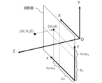
ステップS702において、平行投影変換部312が、3次元データにおける各点(以下、「3次元点」と呼ぶ)を所定の投影面に平行投影することにより、2次元投影画像を生成する。
In step S702, the parallel
図8及び図9を参照して、平行投影変換の詳細を説明する。ステップS800において、平行投影変換部312は、3次元点を平行投影した場合の画像座標値を計算する。カメラ座標系を(X,Y,Z)、投影画像の画像座標系を(x,y)とする。図9の例では、原点Oがセンサユニット20のカメラのレンズの中心(主点)に一致し、Z軸が光軸に重なり、X軸とY軸がカメラの撮像素子の水平方向と垂直方向にそれぞれ平行となるように、カメラ座標系が設定される。また、画像座標系は、画像中心(cx,cy)がカメラ座標系のZ軸上にあり、x軸とy軸がカメラ座標系のX軸とY軸にそれぞれ平行となるように設定される。画像座標系のxy平面が投影面である。すなわち、本実施形態では、カメラの光軸に直交するように、平行投影変換の投影面が設定されている。図9のように座標系を設定した場合、3次元点(Xi,Yi,Zi)に対応する、平行投影変換後の画像座標値(xi,yi)は、
xi=ROUND(Xi/resx+cx)
yi=ROUND(Yi/resy+cy)
により求まる。ROUNDは小数点以下を丸める演算子である。Details of the parallel projection transformation will be described with reference to FIGS. 8 and 9. FIG. In step S800, the parallel
x i =ROUND(X i /res x +c x )
y i =ROUND(Y i /res y +c y )
Determined by ROUND is an operator for rounding to decimal places.
ステップS801において、平行投影変換部312は、画像座標値(xi,yi)に投影された3次元点が既に存在していたかどうかを調べる。具体的には、投影画像の画素(xi,yi)に対し既に3次元点の情報が関連付けられているかどうかがチェックされる。関連付けられている3次元点が未だ無い場合(ステップS801のNO)、平行投影変換部312は、画素(xi,yi)に対し3次元点(Xi,Yi,Zi)の情報を関連付ける(ステップS803)。本実施形態では、3次元点の座標値(Xi,Yi,Zi)を画素(xi,yi)に関連付けるが、これに限らず、3次元点のデプス情報(例えばZiの値)、色情報(例えばRGB値)、輝度情報などを関連付けてもよい。関連付けられている3次元点が既に存在していた場合(ステップS801のYES)、平行投影変換部312は、Ziの値と、既に関連付けられているZの値とを比較し、Ziの方が小さければ(ステップS802のYES)、画素(xi,yi)に関連付けられた情報を3次元点(Xi,Yi,Zi)の情報で上書きする(ステップS803)。このような処理により、複数の3次元点が投影面上の同じ位置に投影される場合には、複数の3次元点のうちカメラに最も近い3次元点の情報が投影画像の生成に用いられることとなる。ステップS800~S803の処理が全ての3次元点について行われたら、図7のステップS703に進む(ステップS804)。In step S801, the parallel
ステップS703において、特徴抽出部313が、投影画像から画像特徴を抽出する。ここで抽出される画像特徴は、テンプレート作成に用いられた画像特徴と同じものである。ステップS704において、テンプレートマッチング部315が、テンプレート記憶部314からテンプレートを読み込み、当該テンプレートを用いたテンプレートマッチング処理によって、投影画像から対象物体を検出する。このとき、異なる視点のテンプレートを用いることで、対象物体の姿勢を認識することもできる。ステップS705において、認識結果出力部316が認識結果を出力する。以上で物体認識処理が終了する。
In step S703, the
(本実施形態の利点)
以上述べた構成及び処理では、3次元データを平行投影することで生成された2次元画像をテンプレートマッチングに利用する。平行投影では、投影面から対象物体までの距離にかかわらず、対象物体は同じ大きさで投影される。それゆえ、平行投影により生成された2次元画像においては、対象物体の像は(その奥行き距離によらず)常に同じ大きさをとる。したがって、単一のサイズのテンプレートだけを用いてマッチングを行えばよいので、従来方法に比べて高速な処理が可能である。また、テンプレートの数及びデータ量を削減できるとともに、ワークメモリの必要量も少なくて済むため、実用性に優れるという利点もある。(Advantages of this embodiment)
In the configuration and processing described above, a two-dimensional image generated by parallel projection of three-dimensional data is used for template matching. In parallel projection, the target object is projected in the same size regardless of the distance from the projection plane to the target object. Therefore, in a two-dimensional image generated by parallel projection, the image of the target object always has the same size (regardless of its depth distance). Therefore, since matching can be performed using only templates of a single size, high-speed processing is possible compared to the conventional method. In addition, the number of templates and the amount of data can be reduced, and the required amount of work memory can be reduced, so there is also the advantage of being excellent in practicality.
また、本実施形態では、テンプレートも平行投影画像から生成することとしたので、テンプレートと平行投影変換により得られた画像における対象物体像とのマッチング精度が向上する。これにより、物体認識処理の信頼性を高めることができる。 Further, in this embodiment, since the template is also generated from the parallel projection image, the accuracy of matching between the template and the target object image in the image obtained by the parallel projection conversion is improved. Thereby, the reliability of object recognition processing can be improved.
また、本実施形態では、カメラの光軸に直交するように投影面を設定したので、カメラ座標系から画像座標系への変換の計算を簡単化でき、平衡投影変換処理の高速化、ひいてはテンプレートマッチングによる物体認識処理の高速化を図ることができる。また、カメラの光軸に直交するように投影面を設定したことで、平行投影変換後の対象物体像の歪みを抑えることもできる。 In addition, in this embodiment, the projection plane is set so as to be orthogonal to the optical axis of the camera. Therefore, the calculation of the conversion from the camera coordinate system to the image coordinate system can be simplified, and the balanced projection conversion process can be speeded up. It is possible to increase the speed of object recognition processing by matching. Further, by setting the projection plane so as to be orthogonal to the optical axis of the camera, it is possible to suppress the distortion of the target object image after parallel projection conversion.
また、複数の3次元点が同一の画素に投影される場合には、カメラに最も近い3次元点の情報のみを用いることとしたので、カメラから見たときの物体同士の重なり(隠れ)を考慮した平行投影像が生成され、テンプレートマッチングによる物体認識処理を精度良く行うことができる。 Also, when a plurality of 3D points are projected onto the same pixel, only the information of the 3D point closest to the camera is used. A parallel projection image that takes into consideration the object is generated, and object recognition processing by template matching can be performed with high accuracy.
<その他>
上記実施形態は、本発明の構成例を例示的に説明するものに過ぎない。本発明は上記の具体的な形態には限定されることはなく、その技術的思想の範囲内で種々の変形が可能である。<Others>
The above-described embodiment is merely an example of the configuration of the present invention. The present invention is not limited to the specific forms described above, and various modifications are possible within the technical scope of the present invention.
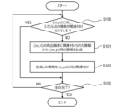
例えば、図10に示す投影点補完処理を、平行投影変換処理(図7のステップS702)の後に行ってもよい。具体的には、平行投影変換部312が、ステップS702で生成された投影画像の各画素(xi,yi)について、3次元点の情報が関連付けられているか否かを調べ(ステップS100)、3次元点の情報が関連付けられていない場合(つまり、投影点が存在しない場合)には、画素(xi,yi)の周辺の画素(例えば4近傍画素や8近傍画素など)に関連付けられている情報に基づいて、画素(xi,yi)用の情報を生成する(ステップS101)。例えば、ニアレストネイバー、バイリニア、バイキュービックなどの補間によって画素(xi,yi)用の情報を生成してもよい。そして、平行投影変換部312は、ステップS101で生成した情報を、画素(xi,yi)に対し関連付ける(ステップS102)。ステップS100~S102の処理を投影画像の全ての画素について実施する。このような処理によって、投影画像の情報量(投影点の数)が増すので、テンプレートマッチングの精度向上が期待できる。For example, the projection point complementing process shown in FIG. 10 may be performed after the parallel projection conversion process (step S702 in FIG. 7). Specifically, the parallel
また、投影面の設定は図9の例に限られない。例えば、カメラ座標系の原点Oの後ろ側(像側)に投影面を配置してもよい。あるいは、投影面が光軸(Z軸)と斜めに交わるように(つまり、投影方向が光軸と非平行になるように)、投影面を配置してもよい。 Also, the setting of the projection plane is not limited to the example in FIG. For example, the projection plane may be arranged on the back side (image side) of the origin O of the camera coordinate system. Alternatively, the projection plane may be arranged so that it obliquely intersects the optical axis (Z-axis) (that is, the projection direction is non-parallel to the optical axis).
<付記>
(1) 各々が3次元情報をもつ複数の点から構成される3次元データを取得する3次元データ取得部(310)と、
前記3次元データの各点をある投影面に平行投影することにより2次元画像を生成する平行投影変換部(312)と、
テンプレートマッチングにより前記2次元画像から対象物体を検出する認識処理部(313、314、315)と、
を有することを特徴とする物体認識装置(2)。<Appendix>
(1) a three-dimensional data acquisition unit (310) for acquiring three-dimensional data composed of a plurality of points each having three-dimensional information;
a parallel projection transformation unit (312) that generates a two-dimensional image by parallel-projecting each point of the three-dimensional data onto a certain projection plane;
a recognition processing unit (313, 314, 315) that detects a target object from the two-dimensional image by template matching;
An object recognition device (2) characterized by comprising:
2:物体認識装置
20:センサユニット
21:画像処理装置
22:ディスプレイ
27:対象物体
30:テンプレート作成装置
31:物体認識処理装置2: Object recognition device 20: Sensor unit 21: Image processing device 22: Display 27: Target object 30: Template creation device 31: Object recognition processing device
Claims (13)
前記3次元データの各点をある投影面に平行投影することにより2次元画像を生成する平行投影変換部と、
テンプレートマッチングにより前記2次元画像から対象物体を検出する認識処理部と、を有し、
前記3次元データは、カメラで撮影された画像を用いて生成されたデータであり、
前記平行投影変換部は、前記カメラの光軸に直交するように前記投影面を設定する
ことを特徴とする物体認識装置。 a three-dimensional data acquisition unit that acquires three-dimensional data composed of a plurality of points each having three-dimensional information;
a parallel projection conversion unit that generates a two-dimensional image by parallel-projecting each point of the three-dimensional data onto a certain projection plane;
a recognition processing unit that detects a target object from the two-dimensional image by template matching ;
The three-dimensional data is data generated using an image captured by a camera,
The object recognition apparatus , wherein the parallel projection conversion unit sets the projection plane so as to be orthogonal to the optical axis of the camera .
前記3次元データの各点をある投影面に平行投影することにより2次元画像を生成する平行投影変換部と、a parallel projection conversion unit that generates a two-dimensional image by parallel-projecting each point of the three-dimensional data onto a certain projection plane;
テンプレートマッチングにより前記2次元画像から対象物体を検出する認識処理部と、を有し、a recognition processing unit that detects a target object from the two-dimensional image by template matching;
前記3次元データの各点は、輝度の情報を有しており、Each point of the three-dimensional data has luminance information,
前記平行投影変換部は、前記3次元データにおける第1の点が前記2次元画像における第1の画素に投影された場合に、前記第1の点の輝度の情報を前記第1の画素に関連付けるThe parallel projection conversion unit associates luminance information of the first point with the first pixel when the first point in the three-dimensional data is projected onto the first pixel in the two-dimensional image.
ことを特徴とする物体認識装置。An object recognition device characterized by:
前記3次元データの各点をある投影面に平行投影することにより2次元画像を生成する平行投影変換部と、a parallel projection conversion unit that generates a two-dimensional image by parallel-projecting each point of the three-dimensional data onto a certain projection plane;
テンプレートマッチングにより前記2次元画像から対象物体を検出する認識処理部と、a recognition processing unit that detects a target object from the two-dimensional image by template matching;
を有し、has
前記3次元データの各点は、色の情報を有しており、Each point of the three-dimensional data has color information,
前記平行投影変換部は、前記3次元データにおける第1の点が前記2次元画像における第1の画素に投影された場合に、前記第1の点の色の情報を前記第1の画素に関連付けることを特徴とする物体認識装置。The parallel projection conversion unit associates color information of the first point with the first pixel when the first point in the three-dimensional data is projected onto the first pixel in the two-dimensional image. An object recognition device characterized by:
前記3次元データの各点をある投影面に平行投影することにより2次元画像を生成する平行投影変換部と、a parallel projection conversion unit that generates a two-dimensional image by parallel-projecting each point of the three-dimensional data onto a certain projection plane;
テンプレートマッチングにより前記2次元画像から対象物体を検出する認識処理部と、を有し、a recognition processing unit that detects a target object from the two-dimensional image by template matching;
前記3次元データは、カメラで撮影された画像を用いて生成されたデータであり、The three-dimensional data is data generated using an image captured by a camera,
前記平行投影変換部は、前記3次元データにおける複数の点が前記投影面上の同じ位置に投影される場合には、前記複数の点のうち前記カメラに最も近い点を前記2次元画像の生成に用いるWhen a plurality of points in the three-dimensional data are projected onto the same position on the projection plane, the parallel projection conversion section converts a point closest to the camera from among the plurality of points to generate the two-dimensional image. used for
ことを特徴とする物体認識装置。An object recognition device characterized by:
ことを特徴とする請求項1~4のうちいずれか1項に記載の物体認識装置。The object recognition device according to any one of claims 1 to 4, characterized in that:
ことを特徴とする請求項2、3、または、5に記載の物体認識装置。6. The object recognition device according to claim 2, 3, or 5, characterized in that:
ことを特徴とする請求項6に記載の物体認識装置。7. The object recognition device according to claim 6, characterized by:
ことを特徴とする請求項1~7のうちいずれか1項に記載の物体認識装置。 The object recognition apparatus according to any one of claims 1 to 7, wherein the recognition processing unit uses, as a template of the target object, a template generated from an image obtained by parallel projection of the target object. .
前記3次元データの各点をある投影面に平行投影することにより2次元画像を生成するステップと、
テンプレートマッチングにより前記2次元画像から対象物体を検出するステップと、
を有し、
前記3次元データは、カメラで撮影された画像を用いて生成されたデータであり、
前記平行投影では、前記カメラの光軸に直交するように前記投影面を設定する
ことを特徴とする物体認識方法。 obtaining three-dimensional data consisting of a plurality of points each having three-dimensional information;
generating a two-dimensional image by parallel projection of each point of the three-dimensional data onto a projection plane;
detecting a target object from the two-dimensional image by template matching;
has
The three-dimensional data is data generated using an image captured by a camera,
In the parallel projection, the object recognition method is characterized in that the projection plane is set so as to be orthogonal to the optical axis of the camera .
前記3次元データの各点をある投影面に平行投影することにより2次元画像を生成するステップと、generating a two-dimensional image by parallel projection of each point of the three-dimensional data onto a projection plane;
テンプレートマッチングにより前記2次元画像から対象物体を検出するステップと、detecting a target object from the two-dimensional image by template matching;
を有し、has
前記3次元データの各点は、輝度の情報を有しており、Each point of the three-dimensional data has luminance information,
前記平行投影では、前記3次元データにおける第1の点が前記2次元画像における第1の画素に投影された場合に、前記第1の点の輝度の情報を前記第1の画素に関連付けるThe parallel projection associates luminance information of the first point with the first pixel when the first point in the three-dimensional data is projected onto the first pixel in the two-dimensional image.
ことを特徴とする物体認識方法。An object recognition method characterized by:
前記3次元データの各点をある投影面に平行投影することにより2次元画像を生成するステップと、generating a two-dimensional image by parallel projection of each point of the three-dimensional data onto a projection plane;
テンプレートマッチングにより前記2次元画像から対象物体を検出するステップと、detecting a target object from the two-dimensional image by template matching;
を有し、has
前記3次元データの各点は、色の情報を有しており、Each point of the three-dimensional data has color information,
前記平行投影では、前記3次元データにおける第1の点が前記2次元画像における第1の画素に投影された場合に、前記第1の点の色の情報を前記第1の画素に関連付けるThe parallel projection associates color information of the first point with the first pixel when the first point in the three-dimensional data is projected onto the first pixel in the two-dimensional image.
ことを特徴とする物体認識方法。An object recognition method characterized by:
前記3次元データの各点をある投影面に平行投影することにより2次元画像を生成するステップと、generating a two-dimensional image by parallel projection of each point of the three-dimensional data onto a projection plane;
テンプレートマッチングにより前記2次元画像から対象物体を検出するステップと、detecting a target object from the two-dimensional image by template matching;
を有し、has
前記3次元データは、カメラで撮影された画像を用いて生成されたデータであり、The three-dimensional data is data generated using an image captured by a camera,
前記平行投影では、前記3次元データにおける複数の点が前記投影面上の同じ位置に投影される場合には、前記複数の点のうち前記カメラに最も近い点を前記2次元画像の生成に用いるIn the parallel projection, when a plurality of points in the three-dimensional data are projected onto the same position on the projection plane, the point closest to the camera among the plurality of points is used to generate the two-dimensional image.
ことを特徴とする物体認識方法。An object recognition method characterized by:
Applications Claiming Priority (1)
| Application Number | Priority Date | Filing Date | Title |
|---|---|---|---|
| PCT/JP2019/023330 WO2020250348A1 (en) | 2019-06-12 | 2019-06-12 | Object recognition device and object recognition method |
Publications (2)
| Publication Number | Publication Date |
|---|---|
| JPWO2020250348A1 JPWO2020250348A1 (en) | 2020-12-17 |
| JP7298687B2 true JP7298687B2 (en) | 2023-06-27 |
Family
ID=73781383
Family Applications (1)
| Application Number | Title | Priority Date | Filing Date |
|---|---|---|---|
| JP2021525479A Active JP7298687B2 (en) | 2019-06-12 | 2019-06-12 | Object recognition device and object recognition method |
Country Status (5)
| Country | Link |
|---|---|
| US (1) | US20220230459A1 (en) |
| EP (1) | EP3961556A4 (en) |
| JP (1) | JP7298687B2 (en) |
| CN (1) | CN113939852A (en) |
| WO (1) | WO2020250348A1 (en) |
Families Citing this family (1)
| Publication number | Priority date | Publication date | Assignee | Title |
|---|---|---|---|---|
| JP7418762B2 (en) * | 2021-08-09 | 2024-01-22 | 株式会社Mujin | Computing systems, methods and non-transitory computer-readable media |
Citations (3)
| Publication number | Priority date | Publication date | Assignee | Title |
|---|---|---|---|---|
| JP2008203991A (en) | 2007-02-16 | 2008-09-04 | Mitsubishi Electric Corp | Image processor |
| CN103065130A (en) | 2012-12-31 | 2013-04-24 | 华中科技大学 | Target identification method of three-dimensional fuzzy space |
| JP2019003407A (en) | 2017-06-15 | 2019-01-10 | オムロン株式会社 | Template creation device, object recognition processing device, template creation method, and program |
Family Cites Families (2)
| Publication number | Priority date | Publication date | Assignee | Title |
|---|---|---|---|---|
| DE102014005181A1 (en) * | 2014-04-03 | 2015-10-08 | Astrium Gmbh | Position and orientation of objects |
| US9424470B1 (en) * | 2014-08-22 | 2016-08-23 | Google Inc. | Systems and methods for scale invariant 3D object detection leveraging processor architecture |
-
2019
- 2019-06-12 EP EP19932513.5A patent/EP3961556A4/en active Pending
- 2019-06-12 JP JP2021525479A patent/JP7298687B2/en active Active
- 2019-06-12 CN CN201980096937.4A patent/CN113939852A/en active Pending
- 2019-06-12 US US17/614,642 patent/US20220230459A1/en active Pending
- 2019-06-12 WO PCT/JP2019/023330 patent/WO2020250348A1/en unknown
Patent Citations (3)
| Publication number | Priority date | Publication date | Assignee | Title |
|---|---|---|---|---|
| JP2008203991A (en) | 2007-02-16 | 2008-09-04 | Mitsubishi Electric Corp | Image processor |
| CN103065130A (en) | 2012-12-31 | 2013-04-24 | 华中科技大学 | Target identification method of three-dimensional fuzzy space |
| JP2019003407A (en) | 2017-06-15 | 2019-01-10 | オムロン株式会社 | Template creation device, object recognition processing device, template creation method, and program |
Also Published As
| Publication number | Publication date |
|---|---|
| CN113939852A (en) | 2022-01-14 |
| EP3961556A4 (en) | 2022-12-07 |
| EP3961556A1 (en) | 2022-03-02 |
| JPWO2020250348A1 (en) | 2020-12-17 |
| US20220230459A1 (en) | 2022-07-21 |
| WO2020250348A1 (en) | 2020-12-17 |
Similar Documents
| Publication | Publication Date | Title |
|---|---|---|
| CN109737874B (en) | Object size measuring method and device based on three-dimensional vision technology | |
| JP6426968B2 (en) | INFORMATION PROCESSING APPARATUS AND METHOD THEREOF | |
| JP6465789B2 (en) | Program, apparatus and method for calculating internal parameters of depth camera | |
| JP4677536B1 (en) | 3D object recognition apparatus and 3D object recognition method | |
| JP6363863B2 (en) | Information processing apparatus and information processing method | |
| JP6554900B2 (en) | Template creation apparatus and template creation method | |
| WO2011115143A1 (en) | Geometric feature extracting device, geometric feature extracting method, storage medium, three-dimensional measurement apparatus, and object recognition apparatus | |
| JP6836561B2 (en) | Image processing device and image processing method | |
| JP6172432B2 (en) | Subject identification device, subject identification method, and subject identification program | |
| JP2021174554A (en) | Image depth determination method and living creature recognition method, circuit, device, storage medium | |
| US20230047211A1 (en) | Method and system for automatic characterization of a three-dimensional (3d) point cloud | |
| CN112802114A (en) | Multi-vision sensor fusion device and method and electronic equipment | |
| JP7298687B2 (en) | Object recognition device and object recognition method | |
| KR101673144B1 (en) | Stereoscopic image registration method based on a partial linear method | |
| JP6198104B2 (en) | 3D object recognition apparatus and 3D object recognition method | |
| JP7251631B2 (en) | Template creation device, object recognition processing device, template creation method, object recognition processing method, and program | |
| KR101741501B1 (en) | Apparatus and Method for Estimation of Distance between Camera and Object | |
| JP6719168B1 (en) | Program, apparatus and method for assigning label to depth image as teacher data | |
| KR102195762B1 (en) | Acquisition method for high quality 3-dimension spatial information using photogrammetry | |
| JP7195785B2 (en) | Apparatus, method and program for generating 3D shape data | |
| JPH0273471A (en) | Estimating method for three-dimensional form | |
| JP6641313B2 (en) | Region extraction device and program | |
| EP2953096B1 (en) | Information processing device, information processing method, system and carrier means | |
| JP7327484B2 (en) | Template creation device, object recognition processing device, template creation method, object recognition processing method, and program | |
| WO2023132275A1 (en) | Object measurement device and object measurement method |
Legal Events
| Date | Code | Title | Description |
|---|---|---|---|
| A621 | Written request for application examination |
Free format text: JAPANESE INTERMEDIATE CODE: A621 Effective date: 20211122 |
|
| A131 | Notification of reasons for refusal |
Free format text: JAPANESE INTERMEDIATE CODE: A131 Effective date: 20230117 |
|
| A521 | Request for written amendment filed |
Free format text: JAPANESE INTERMEDIATE CODE: A523 Effective date: 20230210 |
|
| TRDD | Decision of grant or rejection written | ||
| A01 | Written decision to grant a patent or to grant a registration (utility model) |
Free format text: JAPANESE INTERMEDIATE CODE: A01 Effective date: 20230516 |
|
| A61 | First payment of annual fees (during grant procedure) |
Free format text: JAPANESE INTERMEDIATE CODE: A61 Effective date: 20230529 |
|
| R150 | Certificate of patent or registration of utility model |
Ref document number: 7298687 Country of ref document: JP Free format text: JAPANESE INTERMEDIATE CODE: R150 |