JP7296987B2 - A method of preparing an insertion site for a cannula on a patient's skin, a skin covering unit therefor and a method of use thereof - Google Patents
A method of preparing an insertion site for a cannula on a patient's skin, a skin covering unit therefor and a method of use thereof Download PDFInfo
- Publication number
- JP7296987B2 JP7296987B2 JP2020562826A JP2020562826A JP7296987B2 JP 7296987 B2 JP7296987 B2 JP 7296987B2 JP 2020562826 A JP2020562826 A JP 2020562826A JP 2020562826 A JP2020562826 A JP 2020562826A JP 7296987 B2 JP7296987 B2 JP 7296987B2
- Authority
- JP
- Japan
- Prior art keywords
- wall
- window
- stabilizer
- skin
- patient
- Prior art date
- Legal status (The legal status is an assumption and is not a legal conclusion. Google has not performed a legal analysis and makes no representation as to the accuracy of the status listed.)
- Active
Links
Images


Classifications
-
- A—HUMAN NECESSITIES
- A61—MEDICAL OR VETERINARY SCIENCE; HYGIENE
- A61B—DIAGNOSIS; SURGERY; IDENTIFICATION
- A61B17/00—Surgical instruments, devices or methods, e.g. tourniquets
- A61B17/34—Trocars; Puncturing needles
- A61B17/3403—Needle locating or guiding means
-
- A—HUMAN NECESSITIES
- A61—MEDICAL OR VETERINARY SCIENCE; HYGIENE
- A61M—DEVICES FOR INTRODUCING MEDIA INTO, OR ONTO, THE BODY; DEVICES FOR TRANSDUCING BODY MEDIA OR FOR TAKING MEDIA FROM THE BODY; DEVICES FOR PRODUCING OR ENDING SLEEP OR STUPOR
- A61M25/00—Catheters; Hollow probes
- A61M25/01—Introducing, guiding, advancing, emplacing or holding catheters
- A61M25/02—Holding devices, e.g. on the body
-
- A—HUMAN NECESSITIES
- A61—MEDICAL OR VETERINARY SCIENCE; HYGIENE
- A61B—DIAGNOSIS; SURGERY; IDENTIFICATION
- A61B8/00—Diagnosis using ultrasonic, sonic or infrasonic waves
-
- A—HUMAN NECESSITIES
- A61—MEDICAL OR VETERINARY SCIENCE; HYGIENE
- A61B—DIAGNOSIS; SURGERY; IDENTIFICATION
- A61B8/00—Diagnosis using ultrasonic, sonic or infrasonic waves
- A61B8/08—Detecting organic movements or changes, e.g. tumours, cysts, swellings
- A61B8/0833—Detecting organic movements or changes, e.g. tumours, cysts, swellings involving detecting or locating foreign bodies or organic structures
- A61B8/0841—Detecting organic movements or changes, e.g. tumours, cysts, swellings involving detecting or locating foreign bodies or organic structures for locating instruments
-
- A—HUMAN NECESSITIES
- A61—MEDICAL OR VETERINARY SCIENCE; HYGIENE
- A61B—DIAGNOSIS; SURGERY; IDENTIFICATION
- A61B8/00—Diagnosis using ultrasonic, sonic or infrasonic waves
- A61B8/42—Details of probe positioning or probe attachment to the patient
- A61B8/4272—Details of probe positioning or probe attachment to the patient involving the acoustic interface between the transducer and the tissue
- A61B8/4281—Details of probe positioning or probe attachment to the patient involving the acoustic interface between the transducer and the tissue characterised by sound-transmitting media or devices for coupling the transducer to the tissue
-
- A—HUMAN NECESSITIES
- A61—MEDICAL OR VETERINARY SCIENCE; HYGIENE
- A61F—FILTERS IMPLANTABLE INTO BLOOD VESSELS; PROSTHESES; DEVICES PROVIDING PATENCY TO, OR PREVENTING COLLAPSING OF, TUBULAR STRUCTURES OF THE BODY, e.g. STENTS; ORTHOPAEDIC, NURSING OR CONTRACEPTIVE DEVICES; FOMENTATION; TREATMENT OR PROTECTION OF EYES OR EARS; BANDAGES, DRESSINGS OR ABSORBENT PADS; FIRST-AID KITS
- A61F13/00—Bandages or dressings; Absorbent pads
- A61F13/02—Adhesive plasters or dressings
- A61F13/023—Adhesive plasters or dressings wound covering film layers without a fluid handling layer
-
- A—HUMAN NECESSITIES
- A61—MEDICAL OR VETERINARY SCIENCE; HYGIENE
- A61M—DEVICES FOR INTRODUCING MEDIA INTO, OR ONTO, THE BODY; DEVICES FOR TRANSDUCING BODY MEDIA OR FOR TAKING MEDIA FROM THE BODY; DEVICES FOR PRODUCING OR ENDING SLEEP OR STUPOR
- A61M25/00—Catheters; Hollow probes
- A61M25/01—Introducing, guiding, advancing, emplacing or holding catheters
-
- A—HUMAN NECESSITIES
- A61—MEDICAL OR VETERINARY SCIENCE; HYGIENE
- A61B—DIAGNOSIS; SURGERY; IDENTIFICATION
- A61B17/00—Surgical instruments, devices or methods, e.g. tourniquets
- A61B2017/00831—Material properties
- A61B2017/00902—Material properties transparent or translucent
- A61B2017/00924—Material properties transparent or translucent for ultrasonic waves
-
- A—HUMAN NECESSITIES
- A61—MEDICAL OR VETERINARY SCIENCE; HYGIENE
- A61B—DIAGNOSIS; SURGERY; IDENTIFICATION
- A61B17/00—Surgical instruments, devices or methods, e.g. tourniquets
- A61B17/34—Trocars; Puncturing needles
- A61B17/3403—Needle locating or guiding means
- A61B2017/3405—Needle locating or guiding means using mechanical guide means
- A61B2017/3407—Needle locating or guiding means using mechanical guide means including a base for support on the body
-
- A—HUMAN NECESSITIES
- A61—MEDICAL OR VETERINARY SCIENCE; HYGIENE
- A61B—DIAGNOSIS; SURGERY; IDENTIFICATION
- A61B17/00—Surgical instruments, devices or methods, e.g. tourniquets
- A61B17/34—Trocars; Puncturing needles
- A61B17/3403—Needle locating or guiding means
- A61B2017/3413—Needle locating or guiding means guided by ultrasound
-
- A—HUMAN NECESSITIES
- A61—MEDICAL OR VETERINARY SCIENCE; HYGIENE
- A61B—DIAGNOSIS; SURGERY; IDENTIFICATION
- A61B90/00—Instruments, implements or accessories specially adapted for surgery or diagnosis and not covered by any of the groups A61B1/00 - A61B50/00, e.g. for luxation treatment or for protecting wound edges
- A61B90/04—Protection of tissue around surgical sites against effects of non-mechanical surgery, e.g. laser surgery
-
- A—HUMAN NECESSITIES
- A61—MEDICAL OR VETERINARY SCIENCE; HYGIENE
- A61F—FILTERS IMPLANTABLE INTO BLOOD VESSELS; PROSTHESES; DEVICES PROVIDING PATENCY TO, OR PREVENTING COLLAPSING OF, TUBULAR STRUCTURES OF THE BODY, e.g. STENTS; ORTHOPAEDIC, NURSING OR CONTRACEPTIVE DEVICES; FOMENTATION; TREATMENT OR PROTECTION OF EYES OR EARS; BANDAGES, DRESSINGS OR ABSORBENT PADS; FIRST-AID KITS
- A61F13/00—Bandages or dressings; Absorbent pads
- A61F2013/00089—Wound bandages
- A61F2013/00182—Wound bandages with transparent part
-
- A—HUMAN NECESSITIES
- A61—MEDICAL OR VETERINARY SCIENCE; HYGIENE
- A61F—FILTERS IMPLANTABLE INTO BLOOD VESSELS; PROSTHESES; DEVICES PROVIDING PATENCY TO, OR PREVENTING COLLAPSING OF, TUBULAR STRUCTURES OF THE BODY, e.g. STENTS; ORTHOPAEDIC, NURSING OR CONTRACEPTIVE DEVICES; FOMENTATION; TREATMENT OR PROTECTION OF EYES OR EARS; BANDAGES, DRESSINGS OR ABSORBENT PADS; FIRST-AID KITS
- A61F13/00—Bandages or dressings; Absorbent pads
- A61F2013/00361—Plasters
- A61F2013/00365—Plasters use
- A61F2013/00412—Plasters use for use with needles, tubes or catheters
-
- A—HUMAN NECESSITIES
- A61—MEDICAL OR VETERINARY SCIENCE; HYGIENE
- A61M—DEVICES FOR INTRODUCING MEDIA INTO, OR ONTO, THE BODY; DEVICES FOR TRANSDUCING BODY MEDIA OR FOR TAKING MEDIA FROM THE BODY; DEVICES FOR PRODUCING OR ENDING SLEEP OR STUPOR
- A61M25/00—Catheters; Hollow probes
- A61M25/01—Introducing, guiding, advancing, emplacing or holding catheters
- A61M25/02—Holding devices, e.g. on the body
- A61M2025/0266—Holding devices, e.g. on the body using pads, patches, tapes or the like
- A61M2025/0273—Holding devices, e.g. on the body using pads, patches, tapes or the like having slits to place the pad around a catheter puncturing site
Description
本発明は、カニューレ、電極又はプローブなどの穿刺器具を人体、例えば静脈又は動脈に挿入するときに使用する超音波透過性外科用皮膚カバーユニットに関する。本発明は、特に、穿刺装置を用いた穿刺の正確な位置を視覚化するための超音波装置を含む手順に関する。 BACKGROUND OF THE INVENTION 1. Field of the Invention The present invention relates to an ultrasonically transparent surgical skin covering unit for use when inserting a puncture device such as a cannula, electrode or probe into a human body, such as a vein or artery. More particularly, the present invention relates to procedures involving ultrasound equipment for visualizing the precise location of punctures using a lancing device.
カニューレが体の一部、例えば腕や脚の血管に挿入されるときに、超音波視覚化を使用して血管及びカニューレを視覚化することによって挿入が最適化される。 Insertion is optimized by visualizing the vessel and cannula using ultrasound visualization when the cannula is inserted into a vessel in a part of the body, such as an arm or leg.
米国特許第9393381号及び対応する米国特許出願第2013/0289404号は、この目的のための皮膚カバーユニットを開示している。皮膚カバーユニットは、ポリマーフィルムで作られた超音波透過窓を備え、穿刺部位に隣接する皮膚に接着され、カニューレの挿入中に穿刺部位を画像化するために超音波プローブが配置されている。典型的には、超音波プローブと窓のポリマーフィルムとの間のより良い接触のために、プローブとフィルムとの間にゲルが使用される。プローブを穿刺部位から適切に分離し、ゲルが穿刺部位に流れるのを防ぐために、窓の拡張部分に直立壁が設けられており、穿刺部位から窓を分離している。窓用のフィルムは比較的硬く、直立壁を窓に対して直立した位置にすることができる。選択的に、ユニットは、超音波可視化後に窓からゲルと共にゲル除去層を除去するために、窓の頂部にゲル除去層を備えている。 US Patent No. 9393381 and corresponding US Patent Application No. 2013/0289404 disclose a skin covering unit for this purpose. A skin cover unit is attached to the skin adjacent to the puncture site with an ultrasound transparent window made of a polymer film and has an ultrasound probe positioned for imaging the puncture site during cannula insertion. Typically a gel is used between the probe and the film for better contact between the ultrasound probe and the polymeric film of the window. In order to properly separate the probe from the puncture site and prevent gel from flowing into the puncture site, an upright wall is provided in the window extension to separate the window from the puncture site. Films for windows are relatively stiff and allow the upright walls to be in an upright position against the window. Optionally, the unit includes a gel removal layer on top of the window to remove the gel removal layer along with the gel from the window after ultrasound visualization.
米国特許出願第2013/0289404号に開示されている原理は理論的には健全に見えるが、実際には適切に機能しない。これは、壁を直立させるのに十分なほど硬いフィルムは、患者の皮膚に容易に密着しない傾向があり、超音波伝達が悪いためである。一方、フィルムが良好な皮膚接触と超音波透過のために十分に可撓性があることは、直立壁が直立位置で十分に安定化されないという傾向がある。実際には、この直立壁は、皮膚が壁に平行な方向に湾曲している腕と脚に皮膚カバーユニットが配置されている場合だけ構造的に安定していることが判明している。しかしながら、皮膚カバーユニットを平坦な肌の領域に使用する場合、直立壁はそれ自体では立っていないが、手動で所定の位置に保持する必要がある。この状況では皮膚カバーユニットが最適に機能しないため、これは欠点である。 While the principle disclosed in US Patent Application No. 2013/0289404 appears sound in theory, it does not work properly in practice. This is because films stiff enough to erect walls tend not to adhere easily to the patient's skin, resulting in poor ultrasound transmission. On the other hand, the fact that the film is flexible enough for good skin contact and ultrasound transmission tends to cause the upright walls to not be sufficiently stabilized in the upright position. In practice, this upright wall has been found to be structurally stable only if the skin covering units are placed on the arms and legs where the skin is curved in a direction parallel to the wall. However, when the skin covering unit is used on flat skin areas, the upright wall does not stand by itself, but must be manually held in place. This is a drawback as the skin covering unit does not function optimally in this situation.
従って、本発明の目的は、技術の改善、特に、例えば注射又は採血のために、皮膚の穿刺部位にカニューレ又は他の穿刺装置を挿入するときの超音波支援制御のための改善された皮膚カバーユニットを提供することである。この目的は、以下で詳細に説明されるように、外科用皮膚カバーユニット及びその使用により達成される。 It is therefore an object of the present invention to improve the technique, in particular an improved skin cover for ultrasound assisted control when inserting a cannula or other puncture device into a skin puncture site, e.g. for injection or blood sampling. to provide the unit. This objective is achieved by a surgical skin covering unit and its use, as described in detail below.
皮膚カバーユニットは、窓と、窓の拡張部分にある壁とを備え、壁を窓に対して角度のある向きに曲げるための屈曲領域によって窓に接続されている。 窓は、窓の超音波透過部、典型的には可撓性ポリマーフィルムを覆う超音波透過可撓性シートを備えている。 The skin covering unit comprises a window and a wall at the extension of the window and is connected to the window by a bending region for bending the wall into an angular orientation with respect to the window. The window comprises an ultrasound transparent flexible sheet covering an ultrasound transparent portion of the window, typically a flexible polymer film.
選択的には、窓は、安定化フレームのみでなく可撓性フレームも備え、その中に可撓性シートが設けられている。可撓性シートはフレームに取り付けられ、フレームによって支持されている。例えば、フレームの材料は、可撓性シートよりも厚く、機械的に安定しており、剛性がある。安定化フレームは、皮膚と一緒に容易に曲がるために、超音波透過シートが薄く、可撓性を備え、良好な超音波伝送のために皮膚にしっかりと支えられ、このような安定化フレームは利点がある。 Alternatively, the window comprises not only a stabilizing frame but also a flexible frame, in which the flexible sheet is provided. A flexible sheet is attached to and supported by the frame. For example, the frame material is thicker, mechanically stable, and stiffer than the flexible sheet. The stabilizing frame has a thin and flexible ultrasonic transparent sheet so that it can be easily bent with the skin, and is firmly supported on the skin for good ultrasonic transmission. There are advantages.
窓の第1の側、例えばフレームの片側には、窓を患者の皮膚に接着するための接着剤層が設けられている。窓の反対側の第2の側は、カニューレを皮膚に挿入するときに、窓に隣接する挿入領域を視覚化するための超音波プローブと接触するように構成されている。 A first side of the window, eg one side of the frame, is provided with an adhesive layer for adhering the window to the patient's skin. An opposite second side of the window is configured to contact an ultrasound probe for visualizing an insertion area adjacent the window when the cannula is inserted into the skin.
典型的には、壁は、ポリマーフィルム、紙シート、又は化粧織物又はそれらの組み合わせで作られている。輸送の場合、典型的には、壁は窓の長手方向の拡張部分に設けられ、窓と壁はまっすぐな平坦な状態で詰め込まれる。別の例として、窓と壁が互いに折り畳まれて、使用のために展開する必要があるコンパクトな2重層の構成にされる。 Typically the walls are made of polymer films, paper sheets, or decorative fabrics or combinations thereof. For shipping, the walls are typically provided in the longitudinal extension of the window and the window and wall are packed straight and flat. As another example, windows and walls are folded together into a compact double layer configuration that must be unfolded for use.
皮膚カバーユニットがパッケージから開梱されるとき、壁は、壁が皮膚に対して直立した向きになるように、窓に対して典型的には垂直又は略垂直な方向に折り畳まれる。この折り畳みは、窓を皮膚上に接着する前又は後に行われる。 When the skin covering unit is unpacked from its packaging, the walls are folded in a direction typically perpendicular or nearly perpendicular to the window so that the walls are in an upright orientation against the skin. This folding can be done before or after gluing the window onto the skin.
前述した米国特許第9393381号に対する改善として、カバーユニットは、超音波透過可撓性シートに加えて、スタビライザーの安定化作用によって壁と窓との間の角度がある方向、例えば垂直方向を維持するように構成されたスタビライザーを備えている。 As an improvement over the aforementioned U.S. Pat. No. 9,393,381, the cover unit maintains an angular orientation, e.g. vertical, between the wall and the window due to the stabilizing action of the stabilizer in addition to the ultrasonically transparent flexible sheet. It has a stabilizer configured to
例えば、スタビライザーは窓の超音波透過部の外側に配置されている。選択的に、スタビライザー又はスタビライザーの一部は、窓の超音波透過部の周辺に沿って配置されている。これは、前述した米国特許出願第2013/0289404号とは対照的である。超音波透過フィルム自体は安定化に使用されるため硬くなければならない。これは、適切な超音波を皮膚に伝達するために、皮膚の外形に容易に追従するためフィルムは、滑らかで容易に可撓性があるべきであるため不都合である。 For example, the stabilizer is placed outside the ultrasound transparent portion of the window. Optionally, the stabilizer or part of the stabilizer is arranged along the perimeter of the ultrasound transparent portion of the window. This is in contrast to the aforementioned US Patent Application No. 2013/0289404. The ultrasound transparent film itself must be stiff as it is used for stabilization. This is disadvantageous because the film should be smooth and easily flexible to easily follow the contours of the skin in order to transmit adequate ultrasound to the skin.
例えば、フレームが窓の一部として提供される場合、フレームに対する壁の方向を安定させるために、フレーム及び壁にスタビライザーが設けられる。 For example, if the frame is provided as part of a window, stabilizers are provided on the frame and wall to stabilize the orientation of the wall relative to the frame.
有利なことに、スタビライザーは、典型的には壁が窓に接続されている領域である屈曲領域内又はその領域に設けられる。例えば、スタビライザー自体が曲がることができるので、窓又は壁は、平面又は折り畳み構成から湾曲構成に、屈曲領域あたりで手動にて曲げることができ、この壁は窓に対してある角度で折り曲げられ、例えば、窓に対して垂直な角度に曲がった構成にすることができる。しかしながら、壁が窓に対して例えば垂直方向のような角度がある方向に相対的に曲げられると、スタビライザーは、壁と窓の間の角度がある方向を維持する。典型的には、屈曲領域あたりでの窓に対する壁の曲がりは、屈曲線に沿っている。 Advantageously, the stabilizer is provided in or at the bending area, typically the area where the wall is connected to the window. For example, because the stabilizer itself can bend, a window or wall can be manually bent from a flat or folded configuration to a curved configuration around the bending area, the wall being bent at an angle to the window, For example, it can be in a angled configuration perpendicular to the window. However, when the wall is bent in an angular direction relative to the window, such as perpendicular, the stabilizer maintains an angular orientation between the wall and the window. Typically, the bend of the wall to the window around the bend area is along the bend line.
例えば、スタビライザーは、非弾性的に曲げ可能であり、曲げられたときに選択可能な曲げ状態を採用して維持するように構成され、それによって窓に対する壁の選択された方向を維持する。非弾性スタビライザーが選択した曲げ構成に曲げられるとき、この曲げ構成が維持される。例えば、スタビライザーは、非弾性の曲げ特性を備えた金属ホイルを含んでいる。選択的に、スタビライザーは、非弾性的に曲げ可能なヒンジが提供され、例えば非弾性の曲げ可能なポリマーシート又は金属ホイルが曲げられたときに選択可能な曲げ条件を採用して維持し、それによって窓に対して壁の選択された方向を維持する。 For example, the stabilizer is inelastically bendable and configured to adopt and maintain a selectable bending state when bent, thereby maintaining a selected orientation of the wall relative to the window. When the inelastic stabilizer is bent into the selected bending configuration, this bending configuration is maintained. For example, stabilizers include metal foils with inelastic bending properties. Optionally, the stabilizer is provided with an inelastic bendable hinge, for example, adopting and maintaining a selectable bending condition when the inelastic bendable polymer sheet or metal foil is bent, and which to maintain the selected orientation of the wall relative to the window.
例えば、スタビライザーは、製造中に折り畳まれた2層の構成に曲げられ、窓が壁に接している折り畳まれた位置で供給される。その後、使用時に部分的にまっすぐになる。別の例として、スタビライザーは、製造中に曲げられず、非屈曲構成、典型的に直線構成で供給され、その後、使用のために曲げられる。 For example, the stabilizer may be bent into a folded two-layer configuration during manufacture and supplied in the folded position with the window against the wall. It is then partially straightened in use. As another example, stabilizers are not bent during manufacture and are supplied in an unflexed configuration, typically a straight configuration, and then bent for use.
幾つかの実施形態では、スタビライザーは、壁に固定される第1の部分を備える曲げ可能なシートとして提供される。曲げ可能なシートの第1の部分の拡張部分で、曲げ可能なシートは、壁が窓に対して曲げられると、曲げ可能なシートを窓の第2の側に接着するための接着剤層を備える第2の部を含んでいる。別の例として、曲げ可能なシートの第1の部分は、壁は窓に対して相対的に曲がっていると、使用時に皮膚とは反対側を向いている窓の第2の側に固定され、第2の部分は、壁に取り付けるための接着剤で構成される。 In some embodiments, the stabilizer is provided as a bendable sheet with a first portion secured to the wall. At the extension of the first portion of the bendable sheet, the bendable sheet has an adhesive layer for adhering the bendable sheet to the second side of the window when the wall is bent against the window. a second part comprising: As another example, the first portion of the bendable sheet is secured to the second side of the window facing away from the skin in use when the wall is bent relative to the window. , the second part consists of an adhesive for attachment to the wall.
典型的には、曲げ可能なシートは、最初から壁又は窓に固定された第1の部分のみを備え、前述のように、曲げた後に接着剤によって他の部分に手動で固定される。 Typically, the bendable sheet comprises only a first portion that is initially fixed to the wall or window, and is manually fixed to the other portion by adhesive after bending, as described above.
幾つかの実施形態では、第1のスタビライザー部は壁に固定され、第2のスタビライザー部は、窓のフレームにその部分を固定するために壁の端部で部分を備えている。例えば、第1のスタビライザー部は壁に固定され、第2のスタビライザー部は、壁の2つの対向する端部のそれぞれで部分を備え、方法は、2つの部分を窓のフレームの2つの対向する部分に固定するステップを含んでいる。 In some embodiments, the first stabilizer part is fixed to the wall and the second stabilizer part comprises a portion at the edge of the wall for fixing that portion to the frame of the window. For example, a first stabilizer part may be fixed to a wall and a second stabilizer part may comprise a portion at each of two opposite ends of the wall, and the method may be to attach the two portions to two opposite ends of the window frame. Including the step of fixing to the part.
他の実施形態では、スタビライザーは、窓と壁の両方に既に固定され、曲げた後の曲げ状態を維持する非弾性ヒンジとして機能する。 In other embodiments, the stabilizer is already fixed to both the window and the wall and acts as an inelastic hinge that maintains the bent state after bending.
幾つかの実施形態では、スタビライザーは、締結後、屈曲領域から離れた少なくとも2点間の距離を維持するように構成され、かくして、2点と屈曲領域との間に安定した三角形の構成を形成するように構成されている。例えば、スタビライザーは壁の第1の点とフレームの第2の点に固定され、どちらの点も屈曲領域から離れた距離にある。 In some embodiments, the stabilizer is configured to maintain a distance between at least two points away from the bending area after fastening, thus forming a stable triangular configuration between the two points and the bending area. is configured to For example, the stabilizer is fixed at a first point on the wall and a second point on the frame, both points being a distance away from the bending area.
幾つかの実施形態では、壁は、壁の端部から窓に向かって延びる溝を備えている。幾つかの実施形態では、壁材料にスリットが設けられ、スリットの隣接した対向する2つの端部を押し離すことによって溝を設けることができる。別の例として、溝は、カニューレの挿入を容易にするために適切な幅を備えている。この場合、壁は、壁を患者の皮膚に接着する接着剤を備え、壁が患者の皮膚に接着されている間にカニューレを溝内に配置するための第1の壁側を備えている。第1の壁側の接着剤は、カバー層によって覆われている。以下でより詳細に説明するように、これにより、幾つかの使用時のオプションが提供される。 In some embodiments, the wall includes a groove extending from the edge of the wall toward the window. In some embodiments, the wall material is slit and the groove can be created by pushing two adjacent opposing ends of the slit apart. As another example, the groove has a suitable width to facilitate cannula insertion. In this case, the wall comprises an adhesive for adhering the wall to the patient's skin and comprises a first wall side for positioning the cannula within the groove while the wall is adhered to the patient's skin. The first wall side adhesive is covered by a cover layer. As will be explained in more detail below, this provides several usage options.
例えば、カバー層は、壁が窓に対して相対的に曲げられている間、挿入部位に隣接する直立壁として使用される間に第1の壁側の接着剤上に保持される。選択的に、カバー層は、その後、接着後に溝内にカニューレを収容するために、カニューレの挿入後に患者の皮膚に接着された接着剤及び壁から取り除かれる。別の例として、壁の接着剤のカバー層は、窓の接着剤のカバー層と一緒に除去され、壁及び窓は、超音波検査前に患者の皮膚に接着される。 For example, the cover layer is held on the first wall adhesive while being used as an upstanding wall adjacent to the insertion site while the wall is bent relative to the window. Optionally, the cover layer is then removed from the adhesive and wall adhered to the patient's skin after insertion of the cannula to accommodate the cannula within the groove after adhesion. As another example, the wall adhesive cover layer is removed along with the window adhesive cover layer, and the wall and window are adhered to the patient's skin prior to the ultrasound examination.
幾つかの実施形態では、超音波透過可撓性シート、例えばポリマーフィルムは、可撓性シートから皮膚への超音波伝達のための良好な接触を提供する接着剤で皮膚に接着される。しかしながら、これは必須ではない。 In some embodiments, an ultrasound transparent flexible sheet, such as a polymer film, is adhered to the skin with an adhesive that provides good contact for ultrasound transmission from the flexible sheet to the skin. However, this is not required.
例えば、シートが薄いポリマーフィルムからなる場合、フィルム自体が皮膚に容易に付着し、接着剤が無くても皮膚の外形に追従することがある。原理は、キッチンラップフィルムの付着特性に似ている。しかしながら、そのような薄くて可撓性のあるフィルムの場合、安定化フレームは、安定化フレームがフィルムを保持するだけでなく壁も保持するために必要な安定性を与え、良好な皮膚接触のためにフィルムを十分に薄くできるという利点がある。 For example, if the sheet consists of a thin polymer film, the film itself may easily adhere to the skin and follow the contours of the skin without an adhesive. The principle is similar to the adhesive properties of kitchen wrap film. However, for such thin and flexible films, the stabilizing frame provides the necessary stability so that the stabilizing frame not only holds the film, but also the walls, ensuring good skin contact. This has the advantage that the film can be made sufficiently thin.
超音波プローブと窓の可撓性シートとの間の良好な接触を提供するために、超音波流体、典型的にはゲルを使用することがしばしば有利である。このゲルは、超音波検査の前に超音波透過可撓性シートに適用され、その後に再び取り除かれる。例えば、超音波プローブの使用後にゲルが拭き取られる。別の例として、同様に超音波透過性であるゲル除去ストリップが、可撓性シート上に設けられ、窓の一部を形成する。その後、このゲル除去ストリップは、窓からゲルを拭き取ることを避けるように、ゲルと一緒に超音波透過可撓性シートから取り外されて除去される。例えば、ゲル除去ストリップは、可撓性シートからゲル除去ストリップを手動で除去することによりスタビライザーも除去するため、スタビライザーの少なくとも一部の下、例えばスタビライザー全体の下に延びている。 It is often advantageous to use an ultrasonic fluid, typically a gel, to provide good contact between the ultrasonic probe and the flexible sheet of the window. This gel is applied to the ultrasound transparent flexible sheet prior to ultrasound examination and then removed again. For example, the gel is wiped off after using the ultrasound probe. As another example, a gel removal strip, also ultrasonically transparent, is provided on the flexible sheet and forms part of the window. This gel removal strip is then removed from the ultrasound transparent flexible sheet along with the gel to avoid wiping the gel from the window. For example, the gel-removing strip extends under at least a portion of the stabilizer, eg, under the entire stabilizer, so that manual removal of the gel-removing strip from the flexible sheet also removes the stabilizer.
皮膚カバーユニットの構成要素に適した材料の例は次の通りである。
フレームは、織物、編物、不織布、プラスチック、ゴム、紙、シリコーン、又はそれらの組み合わせである。
超音波透過可撓性シートは、ゴム、紙、シリコーン、プラスチック、又はそれらの組み合わせである。例えば、ポリウレタン又はエラストマーポリエステル(ポリエチレンテレフタレート‐PET)を含む。
壁は、プラスチック、ゴム、紙、シリコーン、織物、編物、不織布、又はそれらの組み合わせである。
スタビライザーは、ポリエステル(ポリエチレンテレフタレート‐PET)、ポリエチレン、ポリアミド(ナイロン)、紙(典型的にはコーティング)又はそれらの組み合わせである。
Examples of materials suitable for the components of the skin covering unit are as follows.
The frame is woven, knitted, nonwoven, plastic, rubber, paper, silicone, or combinations thereof.
The ultrasonically transparent flexible sheet is rubber, paper, silicone, plastic, or combinations thereof. Examples include polyurethanes or elastomeric polyesters (polyethylene terephthalate-PET).
The walls are plastic, rubber, paper, silicone, woven, knitted, non-woven, or combinations thereof.
The stabilizer is polyester (polyethylene terephthalate-PET), polyethylene, polyamide (nylon), paper (typically a coating), or combinations thereof.
超音波透過可撓性シートは、シートが皮膚の動きに追従し、付着して残るために伸縮性及び弾性を含むシートとして理解されるべきである。例えば、可撓性シートは、10~45ミクロンの範囲の厚さを有する。 An ultrasonically transparent flexible sheet should be understood as a sheet that includes stretchability and elasticity because the sheet follows the movement of the skin and remains attached. For example, flexible sheets have a thickness in the range of 10-45 microns.
寸法の非限定的で典型的な例は次の通りである。
幅は、4~10cmである。
長さは、7.5cm~15cmである。
各層の厚さは、10~45ミクロンである。
Non-limiting, representative examples of dimensions are as follows.
The width is 4-10 cm.
The length is between 7.5 cm and 15 cm.
The thickness of each layer is 10-45 microns.
本発明は、穿刺装置としてカニューレの挿入によって例示されたが、それは、例えば神経刺激用の電極又は神経からの電気信号を記録するためのトランスデューサーなどの異なるタイプの穿刺装置の挿入の場合にも同様に適用され得る。皮膚カバーユニットの更なる使用は、化学剤、例えば酸素、代謝産物、又は薬物の分析のためのプローブの挿入である。
本発明は、図面を参照してより詳細に説明される。
Although the invention has been exemplified by the insertion of a cannula as a puncture device, it is also the case for the insertion of different types of puncture devices, such as electrodes for nerve stimulation or transducers for recording electrical signals from nerves. can be applied as well. A further use of the skin covering unit is the insertion of probes for the analysis of chemical agents such as oxygen, metabolites or drugs.
The invention will be explained in more detail with reference to the drawings.
図1a、図1b及び図1cは、2つの別の例の皮膚カバーユニット1のイメージ、及びカバーユニット1の原理の概略図である。カバーユニット1は、窓2と、窓2の拡張部分の壁3とを備える。壁3は、窓2に対して角度のある方向に壁3を方向付けするための屈曲領域4によって窓2に接続されている。窓2は、超音波プローブ19による挿入部位20の超音波検査のために、フレーム5上又はフレーム5内、又は少なくとも部分的にフレーム内に、安定化フレーム5、超音波透過可撓性シート6、及び典型的なポリマーフィルムを含んでいる。可撓性シート6は、フレーム5に取り付けられ、フレーム5によって支持されている。更に、可撓性シート6は、窓2を患者の皮膚8に接着するために、可撓性シート6の第1の側に接着剤7を備えている。
FIGS. 1a, 1b and 1c are images of two alternative skin covering units 1 and schematic representations of the principle of the covering unit 1. FIG. The cover unit 1 comprises a
図1bでは、可撓性シート6は、皮膚8から離れたフレーム側に配置されているように示されているが、可撓性シート6は、別の例として、フレーム5の内側に、又は、フレーム5と、皮膚8に面する接着剤との間に設けることもできる。図1bに示すように、可撓性シート6がフレーム5上に配置される場合、フレーム5は、フレームを皮膚8に接着するために接着剤7を備えることができる。
Although in FIG. 1b the
更なる別の例として、フレーム5のみが皮膚に隣接する側に接着剤を備えており、可撓性シートは皮膚8に対して単に静止している。一部のポリマーフィルムは、接着剤なしでも皮膚に容易に付着し、十分な超音波伝達を有する。
As yet another example, only
可撓性シート6上の接着剤7並びに超音波伝達流体(典型的なゲル14)は、プローブ19からゲル14、可撓性シート6及び接着剤7を介して、皮膚8の中に入る超音波伝達のために、良好な接触を提供する。このゲル14は、超音波検査前に可撓性シート6上に塗布され、その後、再び除去される。
The adhesive 7 on the
更に、皮膚カバーユニット1は、屈曲領域4内又は屈曲領域4にスタビライザー9を備える。スタビライザー9は、例えば、皮膚カバーユニット1が平坦で真っ直ぐな皮膚表面上に配置されたとき、スタビライザー9の安定化作用によってのみ、壁3と窓2との間の角度のある方向を維持するために構成されている。図1a、図1b及び図1cでは、スタビライザー9は、2つの脚部11A、11Bを備えた角度のあるプロフィールとして示され、そのうちの1つの脚部11Aは、壁3に対して第1の安定化接着剤10Aで接着され、他の脚部11Bは、窓2に対して第2の安定化接着剤10Bで接着されて、壁3と窓2との間の角度のある方向を維持している。典型的には、可撓性、超音波透過可撓性シート6は、目及び/又はカメラによる検査のために光透過性でもある。
Furthermore, the skin covering unit 1 comprises a
可撓性シート6が接着剤7を備えた側から遠い側であるフレーム5の上側に設けられている場合、スタビライザー9は、それ自体がフレームに取り付けられている可撓性シートの部分で可撓性シート6に取り付けられている。可撓性シート6がフレーム5内に設けられるだけの場合、代わりに、フレームが可撓性シート6を少なくとも部分的に取り囲むので、スタビライザーはフレーム5に直接的に取り付けられるであろう。可撓性シート6がフレーム5と皮膚8との間に設けられている場合、フレームは、可撓性シート6の反対側の上側に取り付けられるので、スタビライザー9は、フレームに取り付けられるだろう。どちらの場合でも、スタビライザーは、直接又はフレーム上のフィルムを介してフレームに取り付けられる。原理の様々な実施形態及び変形が可能である。
If the
直立している壁3は、カバーシート18によって覆われた壁接着剤17を備え、その使用は、特に、図4及び図5に関連して、以下でより詳細に説明される。
The
スタビライザー9は、図1aに示すように、フレーム5の何れかの側でフレーム5に固定された第2の脚部11Bを有している。しかしながら、壁3に取り付けられた脚部11Aは、壁の一方側の端部から反対側の端部まで壁3を横切って伸びている。この実施形態におけるスタビライザーの構成は、C字形に似ている。
The
図1a、図1b及び図1cに示すように、可撓性シート6は、可撓性シート6の小さい方の部分6´を備えた屈曲領域4の周りに伸びて、小さい方の部分6´が壁2と一緒に上方に屈曲している。
As shown in FIGS. 1a, 1b and 1c, the
図1aの場合に、これは、スタビライザー部分がその脚部11Aと共に壁2の一部を横切って延び、シート6の上方に曲がった小さい方の部分6´を覆って、シート6の周囲に沿って部分的に延びることを意味する。
In the case of FIG. 1a, this means that the stabilizer part extends with its
別の例として、図1cに示すように、スタビライザー9は、可撓性シート6の両側に1つずつ、2つの別個の曲げストリップとして設けられる。各ストリップは、シートの周囲で壁に取り付けられた第1の脚部11Aと、フレーム5に取り付けられた第2の脚部11Bとを有し、シート6は、窓2の超音波透過部を覆っている。
As another example, the
しかしながら、曲がりシート6のこの構成は必須ではなく、可撓性シート6は、屈曲領域4の周りに延在しないものとして以下の概略図に示されている。
However, this configuration of the
図1dの変形実施形態では、シート6は壁2と共に上方に曲げられていないが、屈曲領域4でスタビライザー9の周囲を有する。この場合、シート6は皮膚に対して平坦に設けられるのみである。
In the variant embodiment of FIG. In this case, the
更なる変形として、図1dのフレーム5を備えた壁3及び窓2の構成は、図1cのスタビライザー9のストリップと組み合わせることができる。
As a further variant, the arrangement of
全ての場合において、スタビライザー9は、超音波検査に使用される窓2の部分の外側にある。
スタビライザー9は、最初から窓2及び壁3に取り付けられ、その後、角度を付けられた構成に曲げることができ、これはスタビライザー9の非弾性材料、例えば金属により維持されることに言及されるべきである。
In all cases the
It should be mentioned that the
別の例として、スタビライザー9の一方の脚部11Aが壁3に固定され、もう一方の脚部11Bがまだ窓2に固定されていないか、又はその逆であり、壁と窓の間の向きが調整されると、それぞれ窓又は壁にのみ固定される。この原理のオプションについては、以下で詳しく説明する。
As another example, one
図2aは、カバーユニット1の可能性がある包装及び輸送状態を示している。壁3は、窓2の平坦な拡張部分に向けられている。皮膚に接着するための接着剤7は、取り外し可能なカバーシート12、典型的な紙シートによって覆われる。スタビライザー9の2つの脚部11A及び11Bは、一緒に折り畳まれ、図2bに示されるように展開するように構成されている。第2の安定化接着剤10Bは、図2bに示されるように第2の安定化接着剤10Bから取り除かれる、更なるカバーシート13、典型的な紙シートによって覆われる。一度、図1のようなカバーユニットは、その包装(図示せず)から取り除かれ、更にカバーシート13が第2の安定化接着剤10Bから取り除かれると、壁3が屈曲領域4の周りで窓2に対して角度のある方向に屈曲され、第2の安定化接着剤10Bは、その後、窓2に取り付けられ、窓2に対する壁3の向きを安定化する。皮膚8への取り付けのために、カバーシート12が取り除かれ、窓2の接着剤7が皮膚8に接着される。これは、好ましくは、窓2に対して壁3を屈曲させる前に行われるが、壁3を屈曲させた後に行うこともできる。
FIG. 2a shows a possible packaging and transport situation for the cover unit 1. FIG. The
場合によっては、カバーユニット1は、超音波検査及び穿刺装置の挿入、特にカニューレの挿入、又は他の穿刺装置、例えば電極又はプローブの挿入後に、患者から取り除かれる。他の場合では、カバーユニット1は、検査及び穿刺装置、例えばカニューレの挿入後でも、患者の皮膚8上に取り残される。後者の場合、壁3は、原則として、例えばそれを切り取ることにより、窓2から取り除くことができる。別の例では、壁3は、窓2上に曲げられ、そこに取り残される。これらの場合では、図1bの実施例及び図4及び5の実施例と対照的に、壁3に接着剤17を設ける必要はない。
Optionally, the cover unit 1 is removed from the patient after ultrasound examination and insertion of a lancing device, in particular insertion of a cannula, or insertion of other lancing devices, such as electrodes or probes. In other cases, the cover unit 1 is left on the patient's
しかしながら、以下により詳細に説明するように、壁3は、超音波検査及びカニューレ又は他の穿刺装置の皮膚8への挿入後に、皮膚8に任意に接着される。かくして、接着剤7は、窓2に沿ってのみ延びるように図1bに示されているが、典型的には壁3の下にも設けられている。このような実施形態は、図1b及び図4及び5に示され、以下でより詳細に説明される。
However, the
図3a、図3b、及び図3cは、包装されていない状態から屈曲した構成までの一連の準備ステップを示している。図3aでは、カバーユニット1は、開梱直後は平坦で真っ直ぐな形態にある。壁3は、窓2の真っ直ぐな拡張部分にある。窓2は、皮膚に隣接した側がカバーシート(図示せず)によって覆われているため、まだ透明ではない。しかしながら、一度、このようなカバーシートが取り除かれると、図3bに示されるように、透明な可撓性シート6がフレーム5の内側にはっきりと見える。更に、カバーシート13は、図3aで見られ、図3bの除去の工程で見られる。更なるカバーシート13の除去後、図1Bの第2の脚部11Bに対応する2つのフラップ11B´が図3cに見られる。これらの2つのフラップ11B´は、スタビライザー9の2つの部分であり、2つのフラップ11B´を窓のフレーム5の2つの対向する部分5A、5Bに固定するために、2つのフラップ11B´は、壁3の2つの対向する端部15A、15Bのそれぞれに設けられる。図1aに示されるように、これらのフラップ11B´が窓2に接着されると、壁3は窓2に対してある方向で固定される。
Figures 3a, 3b and 3c show a series of preparatory steps from the unwrapped state to the bent configuration. In Figure 3a, the cover unit 1 is in a flat and straight configuration immediately after unpacking.
複数の機能を提供するために、壁3には、壁3の端から窓2に向かって延びる溝16が設けられている。 図1aに最も示されるように、溝16は、屈曲領域4の近くにあり、可撓性シート6に近接した底部16´を有する。
To provide multiple functions, the
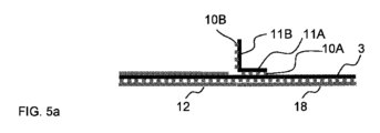
図1b、図4a、図5a及び図5bの概略図に示されるように、壁3は、壁カバーシート18によって覆われる接着剤17を備えた第1の壁側3Aを備えている。壁カバーシート18が取り除かれると、壁3の第1の側3Aは、また、接着剤17によって患者の皮膚8に接着される。
The
初めの形態では、第1の壁側3aの接着剤17は、壁3を直立した構成で使用中にユーザーが第1の壁側3Aの接着剤17上の壁カバーシート18を保持するために、壁カバーシート18によって覆われ、上記で説明され、図1bと図5bに示されるように、壁3が窓2に対して屈曲領域4で屈曲している間に、挿入部位19に隣接した安全な超音波検査のためにスタビライザー9により安定化されている。
In the initial configuration, the adhesive 17 on the first wall side 3a is used for the user to hold the
次に、ユーザーは、穿刺デバイス23、特にカニューレは、溝16の内側に配置されるように、接着剤17から壁カバーシート18を取り除くことを選択することができ、穿刺デバイス、特にカニューレを皮膚8に挿入した後、壁3を患者の皮膚8に接着することも選択することができる。後者の場合、スタビライザー9は、例えばそれを切断することによって、又は窓2または壁3から部分的に取り除くことによって、非アクティブ化する必要がある。スタビライザーの脚フラップ11Bを備えた実施形態では、これらは、非アクティブ化のために、窓2又はフレーム3、又は両方から切り離される。別の例として、スタビライザー9は、非アクティブ化のために切断される。
The user may then choose to remove the
別の例として、ユーザーは、窓2を介してプローブ19を備えた超音波検査を実行している間に、壁3と窓2を選択的に患者の皮膚8に接着し、穿刺器具、特にカニューレを、溝18を介して皮膚8に挿入する。この場合、カバーユニット1は真っ直ぐな状態で使用され、壁3は直立した構成では使用されない。
As another example, the user, while performing an ultrasound examination with
壁3と窓2の両方が皮膚に接着されているカバーユニット1の平坦な構成が図4bに示されている。この図では、スタビライザー9は作動してないが、輸送状態で残されている。
A flat configuration of the cover unit 1 with both the
図4aに示すように、皮膚カバーユニット1の真っ直ぐな輸送状態から開始する時、ユーザーには幾つかのオプションがある。第1のオプションとして、ユーザーは、カバーシート12及び18を取り除き、図4bに示すように、皮膚カバーユニット1が真っ直ぐな状態にある間に、皮膚カバーユニット1をユーザーの皮膚8に接着することができる。第2のオプションとして、ユーザーは、スタビライザー9からカバーシート13を取り除き、図5aに示すように、スタビライザー9を角度のある方向に曲げることができる。その後に、図5b及び図1bのように、壁3を直立した構成に持ち上げる。超音波検査の後、ユーザーは、図4bの構成と同様に、オプションとして、壁3を皮膚8の上に置くことができる。
When starting from the straight transport state of the skin covering unit 1 as shown in Figure 4a, the user has several options. As a first option, the user removes the
このように、カバーユニット1は、複数の機能を有している。一方では、従来技術の機能が維持され、他方では、皮膚8の表面が平坦である場合、スタビライザー9によって安定化される直立壁3の機能が追加される。
Thus, the cover unit 1 has multiple functions. On the one hand, the functionality of the prior art is preserved, and on the other hand, it adds the functionality of the
図6は、スタビライザー9の更なる実施形態を示している。スタビライザー9は、壁3の第1ポイント又は領域21A、及び窓2の第2ポイント又は領域21B、例えばフレーム5に固定され、両ポイント又は領域21A、21Bは、屈曲領域Fから離れている。スタビライザー9は、これらの2つの離れたポイント又は領域21A、21Bを接続し、かくして、2つのポイント又は領域21A、21Bと、屈曲領域4との間に、安定した三角形の構成を形成する。
FIG. 6 shows a further embodiment of
直立壁3は、窓2に対して垂直な方向を有するものとして示されるが、これは厳密には必要ではなく、壁3と窓2との間の角度は、他の角度に調整され、例えば45度~135度の他の角度に調整され得る。
Although the
選択的に、ゲルの除去を容易にするために、ゲル除去ストリップ22は、図7を参照して、可撓性シート6の頂部に設けられている。このゲル除去ストリップ22も超音波透過性であり、可撓性シート6からのゲルの拭き取りを避けられるように、ゲルと一緒に超音波透過可撓性シート6から取り外されて取り除かれる。
Optionally, to facilitate gel removal, a gel removal strip 22 is provided on top of the
図8aは、図7と同様の概略図であるが、使用者が可撓性シート6の表面からゲル除去ストリップ22を引っ張ると、スタビライザー9がゲル除去ストリップ22と一緒に取り外されるように、スタビライザー9の第2の脚部11Bの下に延びるゲル除去ストリップ22を備えている。このために、スタビライザー9の第1の脚部11Aの接着剤10Aが直立壁3から引き剥がされる。スタビライザー9が取り除かれると、直立壁3を皮膚8上に平坦に置くことができ、接着剤17を覆う壁カバーシート18が除去されると、接着剤17によって皮膚8に接着させることができる。この状況は図8bに示される。次に、穿刺装置23は、溝16、皮膚8を介して下にある組織の中へ延びる。
FIG. 8a is a schematic view similar to FIG. 7, but the
ゲル除去ストリップ22は、スタビライザー9の接着剤10A及び第1の脚部11Aの下で直立壁3までの距離を延びることもできることが示されている。この場合、ゲル除去ストリップ22は全体的にスタビライザー9の下に延び、スタビライザー全体がゲル除去ストリップ22と一緒に除去されることに耐える。
本発明のその他の実施態様を以下に記載する。
〔実施態様1〕
患者の皮膚を通してカニューレ又は他の穿刺器具(23)を挿入するときに使用する外科用皮膚カバーユニット(1)であって、
皮膚カバーユニット(1)は、窓(2)及び壁(3)を備え、前記壁(3)は、前記窓(2)の拡張部分に設けられ、前記窓(2)に対して角度のある方向になるように、屈曲領域を曲げるための屈曲領域(4)によって前記窓(2)に接続され、
前記窓(2)は、前記窓(2)を前記患者の皮膚(8)に接着するために、前記窓(2)の第1の側に接着剤層(7)を含み、
前記窓(2)は、前記窓(2)の前記第1の側の反対側である前記窓(2)の第2の側から可撓性シートを通して前記患者を超音波検査するための超音波透過可撓性シート(6)を備え、
前記可撓性シート(6)に加えて前記皮膚カバーユニット(1)は、スタビライザー(9)を備え、前記スタビライザーは、前記屈曲領域(4)内又は前記屈曲領域(4)に設けられ、前記スタビライザー(9)の安定化作用によって前記壁(3)と前記窓(2)との間の前記角度のある方向を維持するように構成されている、
ことを特徴とする外科用皮膚カバーユニット。
〔実施態様2〕
前記シート(6)は、前記窓(2)の超音波透過部を覆い、
前記スタビライザー(9)又は前記スタビライザー(9)の部分(11B)は、前記窓(2)の前記超音波透過部の外側の安定化作用によって、前記窓(2)に対して前記壁(3)を安定させるために、前記窓(2)の前記超音波透過部の外側、又は前記窓(2)の前記超音波透過部の周囲に沿って配置される、実施態様1に記載の外科用皮膚カバー。
〔実施態様3〕
前記窓(2)は、前記超音波透過可撓性シート(6)より安定している安定化フレーム(5)を備え、
超音波透過可撓性シート(6)は、前記フレーム(5)内に設けられ、前記フレーム(5)に取り付けられて前記フレーム(5)によって支持され、
前記スタビライザー(9)は、前記フレーム(5)に対する前記壁(3)の前記方向を安定させるために、前記フレーム(5)及び前記壁(3)上に設けられる、実施態様1又は2に記載の外科用皮膚カバーユニット。
〔実施態様4〕
前記スタビライザー(9)は、
前記壁(3)及び前記窓(2)の一方に固定されている第1のスタビライザー部(11A、21A)と、
前記第1のスタビライザー部(11A、21A)の拡張部分で、前記第1のスタビライザー部(11A、21A)に対して曲げ可能であり、前記壁(3)及び前記窓(2)の他方に固定されている第2のスタビライザー部(11A、21A)と、
を含む屈曲可能なシートである、実施態様1から3の何れか一つに記載の外科用皮膚カバーユニット。
〔実施態様5〕
実施態様3に従属する場合の実施態様4に記載の外科用皮膚カバーユニットであって、第1のスタビライザー部(11A、21A)は、前記壁(3)に固定され、前記第2のスタビライザー部(11B、21B)は、部分(11B´)を前記窓(2)の前記フレーム(5)に固定するために、前記壁(3)の端部(15A、15B)に前記部分(11B´)を備えている、外科用皮膚カバーユニット。
〔実施態様6〕
第2のスタビライザー部(11B、21B)は、曲がった屈曲領域(4)によって前記壁(3)が前記窓(2)に対してある角度に折り曲げられると、前記第2のスタビライザー部(11B、21B)を前記壁(3)及び前記窓(2)の他方に固定するための安定化接着剤(10B)を備えている、実施態様1から5の何れか一つに記載の外科用皮膚カバーユニット。
〔実施態様7〕
前記スタビライザー(9)は、非弾性的に曲げ可能であり、前記窓(2)に対する前記壁(3)の選択された方向を維持するために、曲げられたときに選択可能な曲げ条件を採用して維持するように構成されている、実施態様1から6の何れか一つに記載の外科用皮膚カバーユニット。
〔実施態様8〕
前記スタビライザーが、選択可能な曲げ条件を採用して維持するように構成された、非弾性的に曲げ可能なポリマーフィルム、金属ホイル、又は紙シートを備えている、実施態様6に記載の外科用皮膚カバーユニット。
〔実施態様9〕
前記壁(3)は、前記壁(3)の端部から前記窓(2)に向かって延びる溝(16)を備え、
前記壁(3)は、前記壁(3)を患者の皮膚(8)に接着するための接着剤(17)を備えて前記壁(3)が患者の皮膚(8)に接着されている間に前記溝(16)の内側にカニューレ又は他の穿刺装置(23)を配置するための第1の壁側(3A)を含み、
前記壁(3)が前記窓(2)に対して曲がった方向にある間、付着部位(20)に隣接した直立壁(3)として前記壁(3)の使用中に前記第1の壁側(3A)の接着剤(17)上の壁カバーシート(18)を保持するために前記第1の壁側(3A)の前記接着剤(17)が壁カバーシート(18)によって覆われ、前記壁カバーシート(18)が前記接着剤(17)から選択的に取り外され、前記カニューレ又は他の穿刺器具(23)が皮膚(8)に挿入されている間にカニューレ又は他の穿刺器具(23)を溝(16)内に配置するため前記壁(3)を前記患者の皮膚(8)に接着する、実施態様1から8の何れか一つに記載の外科用皮膚カバーユニット。
〔実施態様10〕
前記皮膚カバーは、ゲル除去ストリップ(22)の除去によって潜在的なゲル(14)を前記第2の側からも除去するために、前記窓(2)の前記第2の側で前記可撓性シート(6)を覆うゲル除去ストリップ(22)を備え、
ゲル除去ストリップ(22)は、前記可撓性シート(6)から前記ゲル除去ストリップ(22)を手動で除去することにより前記スタビライザー(9)も除去するために、前記スタビライザー(9)の少なくとも一部の下に延びている、実施態様1から9の何れか一つに記載の外科用皮膚カバーユニット。
〔実施態様11〕
患者の皮膚(8)上のカニューレ又は他の穿刺器具(23)の挿入部位を準備する方法であって、この方法は、窓(2)及び壁(3)を備えるタイプの皮膚カバーユニット(1)を準備するステップを備え、
前記壁(3)は、前記窓(2)の拡張部分に設けられ、前記窓(2)に対して角度のある方向になるように屈曲領域を曲げるために、屈曲領域(4)によって前記窓(2)に接続され、
前記窓(2)は、前記窓(2)を患者の皮膚(8)上に接着するために、前記窓(2)の第1の側に接着剤層(7)を含み、
前記窓(2)は、前記可撓性シートを通して患者の超音波検査のための超音波透過可撓性シート(6)を備え、
前記方法は、前記患者の前記皮膚(8)上に前記窓(2)の前記第1の側に接着するステップと、接着をする前又は後に、前記窓(2)に対して45度~135度の範囲の角度に、前記壁の前記角度のある方向を変えるための前記屈曲領域(4)を曲げるステップと、前記窓(2)の第2の側に超音波プローブ(19)を適用するステップと、前記患者に前記カニューレ又は他の穿刺器具(23)の制御された挿入のために前記挿入部位(20)を超音波投影するステップと、を含み、
前記可撓性シート(6)に加えて前記皮膚カバーユニット(1)は、スタビライザー(9)を備え、
前記スタビライザーは、前記屈曲領域(4)内又は前記屈曲領域(4)に設けられ、前記スタビライザー(9)の安定化作用によって前記壁(3)と前記窓(2)との間の前記角度のある方向を維持するように構成され、
前記方法は、前記壁(3)が前記挿入部位(20)を前記窓(2)から分離するために、前記窓(2)に対する前記壁(3)の前記角度のある方向を前記スタビライザー(9)によって維持するステップを含む、ことを特徴とする方法。
〔実施態様12〕
前記シート(6)が前記窓(2)の超音波透過部を覆い、
前記方法は、前記スタビライザー(9)又は前記スタビライザーの一部を、前記窓(2)の前記超音波透過部の外側に又は前記窓(2)の超音波透過部の周囲に沿って配置するステップと、少なくとも部分的に前記窓の前記超音波透過部の外側の安定化作用によって、前記窓に対して前記壁を安定させるステップと、を含む、実施態様11に記載の方法。
〔実施態様13〕
前記窓(2)は、前記超音波透過可撓性シート(6)よりも安定した安定化フレーム(5)を備え、
前記超音波透過可撓性シート(6)は、前記フレーム(5)内に設けられ、前記フレーム(5)に取り付けられて前記フレーム(5)によって支持され、
前記方法は、前記フレーム(5)及び前記壁(3)上にスタビライザー(9)を準備するステップと、前記スタビライザーの作用を安定させることによって前記フレーム(5)に対する前記壁(3)の方向を安定させるステップと、を含む、実施態様11又は12に記載の方法。
〔実施態様14〕
前記スタビライザー(9)は、前記壁(3)及び前記窓(2)の一方に固定された第1のスタビライザー部(11A、21A)と、前記第1のスタビライザー部(11A、21A)の拡張部分で、前記第1のスタビライザー部(11A、21A)に対して曲げることができる第2のスタビライザー部(11B、21B)とを備え、
前記第2のスタビライザー部(11B、21B)は、曲がった屈曲領域(4)により前記壁(3)が前記窓(2)に対してある角度に折り曲げられると前記壁(3)及び前記窓(2)の他方に前記第2のスタビライザー部(11B、21B)を固定するための安定化接着剤(10B)を備え、
前記方法は、前記屈曲領域(4)で前記窓(2)に対して前記壁(3)を曲げるステップと、前記壁(3)が前記窓(2)に対して曲げられたときのみに、前記第2のスタビライザー部(11B、21B)を前記壁(3)及び前記窓(2)の他方に固定するステップとを含む、実施態様11から13の何れか一つに記載の方法。
〔実施態様15〕
前記第1のスタビライザー部(11A、21A)は、前記壁(3)に固定され、前記第2のスタビライザー部(11B、21B)は、部分(11B´)を前記窓(2)の前記フレーム(5)に固定するために、前記壁(3)の端部(15A、15B)に前記部分(11B´)を備え、
前記方法は、前記部分(11B´)を前記窓(2)の前記フレームに固定するステップを含む、実施態様13に従属する場合の実施態様14に記載の方法。
〔実施態様16〕
前記第1のスタビライザー部(11A、21A)は、前記壁(3)に固定され、前記第2のスタビライザー部(11B、21B)は、前記壁(3)の2つの対向する各端部(15A、15B)で部分(11B´)を備え、前記方法は、前記窓(2)の前記フレーム(5)の2つの対向する部分(5A、5B)に2つの前記部分(11B´)を固定するステップを含む、実施態様15に記載の方法。
〔実施態様17〕
前記スタビライザー(9)は、非弾性的に曲げることが可能であり、前記窓(2)に対する前記壁(3)の選択された方向を維持するために曲げられるときに、選択可能な曲げ条件が採用されて維持されるように構成され、
前記方法は、前記選択された屈曲構成に前記スタビライザー(9)を非弾性的に曲げるステップと、前記スタビライザー(9)が前記屈曲構成を維持するステップと含む、実施態様11から16の何れか一つに記載の方法。
〔実施態様18〕
前記壁(3)は、前記壁(3)の端部から前記窓(2)に向かって延びる溝(16)を備え、
前記壁(3)は、前記壁(3)を前記患者の皮膚(8)に接着するための接着剤(17)を備え、前記壁(3)が前記患者の前記皮膚に接着されている間に前記カニューレ又は他の穿刺装置(23)を前記溝(16)の内側に配置するための第1の壁側(3A)を備え、
前記第1の壁側(3A)の前記接着剤(17)は、壁カバーシート(18)によって覆われ、
前記方法は、前記壁(3)が前記窓(2)に対して曲がった方向にある間、付着部位(20)に隣接した直立壁(3)として前記壁(3)の使用中に前記第1の壁側(3A)の接着剤(17)上の壁カバーシート(18)を保持するステップと、前記壁カバーシート(18)が前記接着剤(17)から選択的に取り外されるステップと、前記カニューレ又は他の穿刺器具(23)が前記皮膚(8)に挿入されている間に前記カニューレ又は他の穿刺器具(23)を溝(16)内に配置するために前記壁(3)を前記患者の皮膚(8)に接着するステップと、を含む、実施態様11から17の何れか一つに記載の方法。
〔実施態様19〕
前記外科用皮膚カバーユニットは、ゲル除去ストリップの除去によって前記第2の側から潜在的なゲル(14)を除去するために、前記窓(2)の第2の側で前記可撓性シート(6)を覆うゲル除去ストリップ(22)を備え、
前記ゲル除去ストリップ(22)は、前記スタビライザー(9)の少なくとも一部の下に延びて、前記方法は、前記ゲル除去ストリップ(22)を前記可撓性シート(6)から手動で除去し、除去作用によって前記スタビライザー(9)も除去するステップを含む、実施態様11から18の何れか一つに記載の方法。
〔実施態様20〕
カニューレ又は他の穿刺装置(23)の挿入部位(20)を、患者の前記皮膚上の超音波プローブ(19)から分離する、実施態様1から10の何れか一つに記載の皮膚カバーユニットの使用方法。
It is shown that the gel removal strip 22 can also extend the distance to the
Other embodiments of the invention are described below.
[Embodiment 1]
A surgical skin covering unit (1) for use in inserting a cannula or other piercing device (23) through the skin of a patient, comprising:
A skin covering unit (1) comprises a window (2) and a wall (3), said wall (3) being provided in an extension of said window (2) and angled with respect to said window (2). connected to said window (2) by a bending region (4) for bending the bending region so that it is in the direction of
said window (2) comprises an adhesive layer (7) on a first side of said window (2) for adhering said window (2) to said patient's skin (8);
Said window (2) is adapted for ultrasonic examination of said patient through a flexible sheet from a second side of said window (2) opposite said first side of said window (2). comprising a transparent flexible sheet (6),
In addition to said flexible sheet (6), said skin covering unit (1) comprises a stabilizer (9), said stabilizer being provided in or at said bending area (4), said configured to maintain said angular orientation between said wall (3) and said window (2) by a stabilizing action of a stabilizer (9);
A surgical skin covering unit characterized by:
[Embodiment 2]
The sheet (6) covers the ultrasonic transmission part of the window (2),
Said stabilizer (9) or part (11B) of said stabilizer (9) is placed against said window (2) by a stabilizing action outside said ultrasound transparent part of said window (2), said wall (3) 2. A surgical skin according to claim 1, disposed outside said ultrasound transparent portion of said window (2) or along the perimeter of said ultrasound transparent portion of said window (2) to stabilize the cover.
[Embodiment 3]
said window (2) comprises a stabilizing frame (5) that is more stable than said ultrasound transparent flexible sheet (6);
an ultrasound transparent flexible sheet (6) is provided within said frame (5), attached to said frame (5) and supported by said frame (5);
3. According to
[Embodiment 4]
The stabilizer (9) is
a first stabilizer part (11A, 21A) fixed to one of said wall (3) and said window (2);
an extension of said first stabilizer part (11A, 21A), bendable relative to said first stabilizer part (11A, 21A) and fixed to the other of said wall (3) and said window (2); a second stabilizer section (11A, 21A),
4. A surgical skin covering unit according to any one of embodiments 1-3, which is a bendable sheet comprising:
[Embodiment 5]
A surgical skin covering unit according to
[Embodiment 6]
The second stabilizer part (11B, 21B) is flexed when said wall (3) is bent at an angle with respect to said window (2) by a curved bending area (4). 21B) to the other of said wall (3) and said window (2) with a stabilizing adhesive (10B). unit.
[Embodiment 7]
Said stabilizer (9) is inelastically bendable and adopts a selectable bending condition when bent to maintain a selected orientation of said wall (3) with respect to said window (2). 7. A surgical skin covering unit according to any one of embodiments 1-6, wherein the surgical skin covering unit is configured to maintain a
[Embodiment 8]
7. The surgical device of
[Embodiment 9]
said wall (3) comprises a groove (16) extending from the end of said wall (3) towards said window (2);
The wall (3) comprises an adhesive (17) for adhering the wall (3) to the patient's skin (8) while the wall (3) is adhered to the patient's skin (8). a first wall side (3A) for placing a cannula or other puncture device (23) inside said groove (16) in
said first wall side during use of said wall (3) as an upright wall (3) adjacent to an attachment site (20) while said wall (3) is in a curved orientation with respect to said window (2); said adhesive (17) on said first wall side (3A) is covered by a wall covering sheet (18) to hold the wall covering sheet (18) on said adhesive (17) of (3A), said The wall covering sheet (18) is selectively removed from the adhesive (17) and the cannula or other piercing device (23) is removed while the cannula or other piercing device (23) is inserted into the skin (8). 9. Surgical skin covering unit according to any one of the preceding claims, wherein said wall (3) is adhered to said patient's skin (8) to locate ) within a groove (16).
[Embodiment 10]
The skin covering is flexible at the second side of the window (2) to remove potential gel (14) from the second side as well by removal of a gel removal strip (22). comprising a gel removal strip (22) covering the sheet (6);
A gel removal strip (22) is attached to at least one of said stabilizers (9) in order to also remove said stabilizer (9) by manually removing said gel removal strip (22) from said flexible sheet (6). 10. A surgical skin covering unit according to any one of embodiments 1-9, extending under the body.
[Embodiment 11]
A method of preparing an insertion site for a cannula or other puncture device (23) on the skin (8) of a patient, the method comprising a skin covering unit (1) of the type comprising a window (2) and a wall (3). ), and
Said wall (3) is provided at the extension of said window (2) and is separated by a bending region (4) in order to bend said bending region in an angular direction with respect to said window (2). (2) connected to
said window (2) comprises an adhesive layer (7) on a first side of said window (2) for adhering said window (2) onto a patient's skin (8);
said window (2) comprises an ultrasound transparent flexible sheet (6) for ultrasound examination of a patient through said flexible sheet;
The method comprises the steps of: gluing the first side of the window (2) onto the skin (8) of the patient; bending said bending region (4) for changing said angular orientation of said wall to an angle in the range of degrees; and applying an ultrasonic probe (19) to a second side of said window (2). and ultrasound imaging said insertion site (20) for controlled insertion of said cannula or other puncture device (23) into said patient;
The skin covering unit (1) in addition to the flexible sheet (6) comprises a stabilizer (9),
Said stabilizer is provided in or at said bending area (4) and the stabilizing action of said stabilizer (9) reduces said angle between said wall (3) and said window (2). configured to maintain an orientation,
Said method aligns said angular orientation of said wall (3) with respect to said window (2) so that said wall (3) separates said insertion site (20) from said window (2). ).
[Embodiment 12]
The sheet (6) covers the ultrasonic transmission part of the window (2),
The method comprises placing the stabilizer (9) or part of the stabilizer outside or along the perimeter of the ultrasound transparent part of the window (2). and stabilizing the wall relative to the window, at least in part by a stabilizing effect outside the ultrasound transparent portion of the window.
[Embodiment 13]
said window (2) comprises a stabilizing frame (5) that is more stable than said ultrasound transparent flexible sheet (6);
said ultrasonically transparent flexible sheet (6) is provided in said frame (5), attached to said frame (5) and supported by said frame (5);
Said method comprises the steps of providing a stabilizer (9) on said frame (5) and said wall (3); 13. A method according to
[Embodiment 14]
Said stabilizer (9) comprises a first stabilizer part (11A, 21A) fixed to one of said wall (3) and said window (2) and an extension part of said first stabilizer part (11A, 21A) and a second stabilizer section (11B, 21B) that can be bent with respect to the first stabilizer section (11A, 21A),
Said second stabilizer part (11B, 21B) is adapted to bend said wall (3) and said window (2) when said wall (3) is bent at an angle with respect to said window (2) by a curved bending area (4). 2) comprises a stabilizing adhesive (10B) for fixing the second stabilizer part (11B, 21B) to the other,
Said method comprises the step of bending said wall (3) against said window (2) at said bend region (4), and only when said wall (3) is bent against said window (2), and fixing said second stabilizer part (11B, 21B) to the other of said wall (3) and said window (2).
[Embodiment 15]
Said first stabilizer part (11A, 21A) is fixed to said wall (3) and said second stabilizer part (11B, 21B) connects part (11B') to said frame (2) of said window (2). 5) with said portions (11B') at the ends (15A, 15B) of said walls (3) for fixing to
15. A method according to
[Embodiment 16]
Said first stabilizer part (11A, 21A) is fixed to said wall (3) and said second stabilizer part (11B, 21B) is attached to each of the two opposite ends (15A) of said wall (3). , 15B), said method fixing two said parts (11B') to two opposite parts (5A, 5B) of said frame (5) of said window (2). 16. A method according to embodiment 15, comprising the steps of:
[Embodiment 17]
Said stabilizer (9) is inelastically bendable and has a selectable bending condition when bent to maintain a selected orientation of said wall (3) with respect to said window (2). configured to be adopted and maintained,
17. The method according to any one of claims 11 to 16, wherein the method comprises the steps of inelastically bending the stabilizer (9) into the selected bent configuration and maintaining the stabilizer (9) in the bent configuration. the method described in Section 1.
[Embodiment 18]
said wall (3) comprises a groove (16) extending from the end of said wall (3) towards said window (2);
The wall (3) comprises an adhesive (17) for adhering the wall (3) to the patient's skin (8) while the wall (3) is adhered to the patient's skin. a first wall side (3A) for locating said cannula or other puncture device (23) inside said groove (16);
said adhesive (17) on said first wall side (3A) is covered by a wall covering sheet (18);
The method comprises using the wall (3) as an upstanding wall (3) adjacent to the attachment site (20) while the wall (3) is in a curved orientation with respect to the window (2). holding a wall covering sheet (18) on adhesive (17) on one wall side (3A), said wall covering sheet (18) being selectively removed from said adhesive (17); said wall (3) for positioning said cannula or other piercing device (23) in groove (16) while said cannula or other piercing device (23) is inserted into said skin (8); and adhering to the patient's skin (8).
[Embodiment 19]
Said surgical skin cover unit is positioned on said flexible sheet (14) on the second side of said window (2) to remove potential gel (14) from said second side by removal of a gel removal strip. 6) with a gel removal strip (22) covering
The gel removal strip (22) extends under at least a portion of the stabilizer (9) and the method includes manually removing the gel removal strip (22) from the flexible sheet (6), 19. A method according to any one of embodiments 11 to 18, comprising also removing said stabilizer (9) by a removing action.
[Embodiment 20]
11. A skin covering unit according to any one of the preceding claims, separating an insertion site (20) for a cannula or other piercing device (23) from an ultrasound probe (19) on said skin of a patient. how to use.
1 カバーユニット
2 窓
3 壁
3A 第一の壁側
4 屈曲領域
5 安定化フレーム
5A、5B フレームの対向する部分
6 フレーム5内の超音波透過可撓性シート、典型的なポリマーフィルム
7 接着剤
8 皮膚
9 スタビライザー
10A、10B 第1及び第2の安定化接着剤
11A、11B スタビライザー9の例としての屈曲プロフィールの第1及び第2の脚部
11B´ スタビライザー9の2つの部分としてのフラップ
12 接着剤7を覆い、取り外し可能なカバーシート、典型的な紙シート
13 第2のスタビライザー接着剤11Bを覆うカバーシート
14 ゲル
15A、15B 壁3の対向する端
16 壁3の溝
17 壁3の第1の側3A上の接着剤
18 接着剤17を覆うための壁カバーシート
19 超音波プローブ
20 挿入部位
21 スタビライザー9の取り付け領域
22 ゲル除去ストリップ
23 カニューレ、又はオプションでの他の穿刺器具
1
Claims (12)
皮膚カバーユニット(1)は、窓(2)及び壁(3)を備え、前記壁(3)は、前記窓(2)の拡張部分に設けられ、前記窓(2)に対して角度のある方向になるように、屈曲領域を曲げるための屈曲領域(4)によって前記窓(2)に接続され、
前記窓(2)は、前記窓(2)を前記患者の皮膚(8)に接着するために、前記窓(2)の第1の側に接着剤層(7)を含み、
前記窓(2)は、前記窓(2)の前記第1の側の反対側である前記窓(2)の第2の側から可撓性シートを通して前記患者を超音波検査するための超音波透過可撓性シート(6)を備え、
前記可撓性シート(6)に加えて前記皮膚カバーユニット(1)は、スタビライザー(9)を備え、前記スタビライザー(9)は、前記屈曲領域(4)内又は前記屈曲領域(4)に設けられ、前記スタビライザー(9)の安定化作用によって前記壁(3)と前記窓(2)との間の前記角度のある方向を維持するように構成され、
前記スタビライザー(9)は、前記壁(3)に固定されている第1のスタビライザー部(11A、21A)と、前記第1のスタビライザー部(11A、21A)の拡張部分で、前記第1のスタビライザー部(11A、21A)に対して曲げ可能であり、前記窓(2)に固定されている第2のスタビライザー部(11A、21A)と、を含む屈曲可能なシートである、
ことを特徴とする外科用皮膚カバーユニット。 A surgical skin covering unit (1) for use in inserting a cannula or other piercing device (23) through the skin of a patient, comprising:
A skin covering unit (1) comprises a window (2) and a wall (3), said wall (3) being provided in an extension of said window (2) and angled with respect to said window (2). connected to said window (2) by a bending region (4) for bending the bending region so that it is in the direction of
said window (2) comprises an adhesive layer (7) on a first side of said window (2) for adhering said window (2) to said patient's skin (8);
Said window (2) is adapted for ultrasonic examination of said patient through a flexible sheet from a second side of said window (2) opposite said first side of said window (2). comprising a transparent flexible sheet (6),
In addition to said flexible sheet (6), said skin covering unit (1) comprises a stabilizer (9), said stabilizer (9) being provided in or at said bending area (4). configured to maintain said angular orientation between said wall (3) and said window (2) by the stabilizing action of said stabilizer (9);
Said stabilizer (9) comprises a first stabilizer part (11A, 21A) fixed to said wall (3) and an extension part of said first stabilizer part (11A, 21A), said first stabilizer a second stabilizer part (11A, 21A) bendable with respect to the part (11A, 21A) and fixed to said window (2);
A surgical skin covering unit characterized by:
前記壁(3)は、前記壁(3)を患者の皮膚(8)に接着するための接着剤(17)を備えて前記壁(3)が患者の皮膚(8)に接着されている間に前記溝(16)の内側にカニューレ又は他の穿刺装置を配置するための第1の壁側(3A)を含み、
前記壁(3)が前記窓(2)に対して曲がった方向にある間、付着部位(20)に隣接した直立壁(3)として前記壁(3)の使用中に前記第1の壁側(3A)の接着剤(17)上の壁カバーシート(18)を保持するために前記第1の壁側(3A)の前記接着剤(17)が壁カバーシート(18)によって覆われ、前記壁カバーシート(18)が前記接着剤(17)から選択的に取り外され、前記カニューレ又は他の穿刺器具が皮膚(8)に挿入されている間にカニューレ又は他の穿刺器具を溝(16)内に配置するため前記壁(3)を前記患者の皮膚(8)に接着する、請求項1から4の何れか1項に記載の外科用皮膚カバーユニット。 said wall (3) comprises a groove (16) extending from the end of said wall (3) towards said window (2);
The wall (3) comprises an adhesive (17) for adhering the wall (3) to the patient's skin (8) while the wall (3) is adhered to the patient's skin (8). a first wall side (3A) for placing a cannula or other puncture device inside said groove (16) in
said first wall side during use of said wall (3) as an upright wall (3) adjacent to an attachment site (20) while said wall (3) is in a curved orientation with respect to said window (2); said adhesive (17) on said first wall side (3A) is covered by a wall covering sheet (18) to hold the wall covering sheet (18) on said adhesive (17) of (3A), said A wall covering sheet (18) is selectively removed from the adhesive (17) to allow the cannula or other piercing device to pass through the groove (16) while the cannula or other piercing device is being inserted into the skin (8). 5. Surgical skin covering unit according to any one of claims 1 to 4, wherein the wall (3) is glued to the patient's skin (8) for placement therein.
ゲル除去ストリップ(22)は、前記可撓性シート(6)から前記ゲル除去ストリップ(22)を手動で除去することにより前記スタビライザー(9)も除去するために、前記スタビライザー(9)の少なくとも一部の下に延びている、請求項1から5の何れか1項に記載の外科用皮膚カバーユニット。 The skin covering is flexible at the second side of the window (2) to remove potential gel (14) from the second side as well by removal of a gel removal strip (22). comprising a gel removal strip (22) covering the sheet (6);
A gel removal strip (22) is attached to at least one of said stabilizers (9) in order to also remove said stabilizer (9) by manually removing said gel removal strip (22) from said flexible sheet (6). 6. A surgical skin covering unit according to any one of claims 1 to 5, extending under the body.
前記壁(3)は、前記窓(2)の拡張部分に設けられ、前記窓(2)に対して角度のある方向になるように屈曲領域を曲げるために、屈曲領域(4)によって前記窓(2)に接続され、
前記窓(2)は、前記窓(2)を患者の皮膚(8)上に接着するために、前記窓(2)の第1の側に接着剤層(7)を含み、
前記窓(2)は、可撓性シートを通して患者の超音波検査のための超音波透過可撓性シート(6)を備え、
前記方法は、前記窓(2)に対して45度~135度の範囲の角度に、前記壁の前記角度のある方向を変えるための前記屈曲領域(4)を曲げるステップを含み、
前記可撓性シート(6)に加えて前記皮膚カバーユニット(1)は、スタビライザー(9)を備え、
前記スタビライザー(9)は、前記屈曲領域(4)内又は前記屈曲領域(4)に設けられ、前記スタビライザー(9)の安定化作用によって前記壁(3)と前記窓(2)との間の前記角度のある方向を維持するように構成され、
前記方法は、前記壁(3)が挿入部位(20)を前記窓(2)から分離するために、前記窓(2)に対する前記壁(3)の前記角度のある方向を前記スタビライザー(9)によって維持するステップを含み、
前記スタビライザー(9)は、前記壁(3)又は前記窓(2)の一方に固定された第1のスタビライザー部(11A、21A)と、前記第1のスタビライザー部(11A、21A)の拡張部分で、前記第1のスタビライザー部(11A、21A)に対して曲げることができる第2のスタビライザー部(11B、21B)とを備え、前記第2のスタビライザー部(11B、21B)は、前記壁(3)及び前記窓(2)の一方に固定され、前記方法は、前記屈曲領域(4)で前記窓(2)に対して前記壁(3)を前記壁(3)と前記窓(2)との間の角度のある方向に曲げるステップを含む、
ことを特徴とする方法。 A method of preparing an insertion site for a cannula or other puncture device (23) on the skin (8) of a patient, the method comprising a skin covering unit (1) of the type comprising a window (2) and a wall (3). ), and
Said wall (3) is provided at the extension of said window (2) and is separated by a bending region (4) in order to bend said bending region in an angular direction with respect to said window (2). (2) connected to
said window (2) comprises an adhesive layer (7) on a first side of said window (2) for adhering said window (2) onto a patient's skin (8);
said window (2) comprises an ultrasound transparent flexible sheet (6) for ultrasound examination of the patient through the flexible sheet;
The method includes bending the bending region (4) for changing the angular orientation of the wall to an angle in the range of 45 degrees to 135 degrees with respect to the window (2);
The skin covering unit (1) in addition to the flexible sheet (6) comprises a stabilizer (9),
Said stabilizer (9) is provided in or on said bending area (4), and the stabilizing action of said stabilizer (9) allows the separation between said wall (3) and said window (2). configured to maintain said angular orientation;
The method includes aligning the angular orientation of the wall (3) with respect to the window (2) so that the wall (3) separates the insertion site (20) from the window (2). maintaining by
Said stabilizer (9) comprises a first stabilizer part (11A, 21A) fixed to one of said wall (3) or said window (2) and an extension part of said first stabilizer part (11A, 21A) And a second stabilizer part (11B, 21B) that can be bent with respect to the first stabilizer part (11A, 21A), and the second stabilizer part (11B, 21B) is provided with the wall ( 3) and fixed to one of said window (2), said method moving said wall (3) against said window (2) at said bending region (4). comprising bending in a direction at an angle between
A method characterized by:
前記壁(3)は、前記壁(3)を前記患者の皮膚(8)に接着するための接着剤(17)を備え、前記壁(3)が前記患者の前記皮膚に接着されている間に前記カニューレ又は他の穿刺装置を前記溝(16)の内側に配置するための第1の壁側(3A)を備え、
前記第1の壁側(3A)の前記接着剤(17)は、壁カバーシート(18)によって覆われ、
前記方法は、前記壁(3)が前記窓(2)に対して曲がった方向にある間、付着部位(20)に隣接した直立壁(3)として前記壁(3)の使用中に前記第1の壁側(3A)の接着剤(17)上の壁カバーシート(18)を保持するステップと、前記壁カバーシート(18)が前記接着剤(17)から選択的に取り外されるステップと、前記カニューレ又は他の穿刺器具が前記皮膚(8)に挿入されている間に前記カニューレ又は他の穿刺器具を溝(16)内に配置するために前記壁(3)を前記患者の皮膚(8)に接着するステップと、を含む、請求項7から10の何れか1項に記載の方法。 said wall (3) comprises a groove (16) extending from the end of said wall (3) towards said window (2);
The wall (3) comprises an adhesive (17) for adhering the wall (3) to the patient's skin (8) while the wall (3) is adhered to the patient's skin. a first wall side (3A) for placing the cannula or other puncture device inside the groove (16) in
said adhesive (17) on said first wall side (3A) is covered by a wall covering sheet (18);
The method comprises using the wall (3) as an upstanding wall (3) adjacent to the attachment site (20) while the wall (3) is in a curved orientation with respect to the window (2). holding a wall covering sheet (18) on adhesive (17) on one wall side (3A), said wall covering sheet (18) being selectively removed from said adhesive (17); The wall (3) is positioned against the patient's skin (8) to locate the cannula or other piercing device within a groove (16) while the cannula or other piercing device is inserted into the skin (8). ), the method according to any one of claims 7-10.
前記ゲル除去ストリップ(22)は、前記スタビライザー(9)の少なくとも一部の下に延びて、前記方法は、前記ゲル除去ストリップ(22)を前記可撓性シート(6)から手動で除去し、除去作用によって前記スタビライザー(9)も除去するステップを含む、請求項7から11の何れか1項に記載の方法。 A surgical skin cover unit is provided with said flexible sheet (6) on the second side of said window (2) for removing potential gel (14) from said second side by removal of a gel removal strip. ) with a gel removal strip (22) covering the
The gel removal strip (22) extends under at least a portion of the stabilizer (9) and the method includes manually removing the gel removal strip (22) from the flexible sheet (6), 12. A method according to any one of claims 7 to 11, comprising removing also the stabilizer (9) by a removing action.
Applications Claiming Priority (5)
| Application Number | Priority Date | Filing Date | Title |
|---|---|---|---|
| US201862621651P | 2018-01-25 | 2018-01-25 | |
| US62/621,651 | 2018-01-25 | ||
| DKPA201870085 | 2018-02-12 | ||
| DKPA201870085A DK201870085A1 (en) | 2018-02-12 | 2018-02-12 | A method for preparing an insertion site for a cannula on a skin of a patient, a skin cover unit therefore and its use |
| PCT/DK2019/050032 WO2019145009A1 (en) | 2018-01-25 | 2019-01-25 | A method for preparing an insertion site for a cannula on a skin of a patient, a skin cover unit therefore and its use |
Publications (3)
| Publication Number | Publication Date |
|---|---|
| JP2021511946A JP2021511946A (en) | 2021-05-13 |
| JPWO2019145009A5 JPWO2019145009A5 (en) | 2022-01-28 |
| JP7296987B2 true JP7296987B2 (en) | 2023-06-23 |
Family
ID=69156111
Family Applications (1)
| Application Number | Title | Priority Date | Filing Date |
|---|---|---|---|
| JP2020562826A Active JP7296987B2 (en) | 2018-01-25 | 2019-01-25 | A method of preparing an insertion site for a cannula on a patient's skin, a skin covering unit therefor and a method of use thereof |
Country Status (6)
| Country | Link |
|---|---|
| US (1) | US11903609B2 (en) |
| EP (1) | EP3743149A4 (en) |
| JP (1) | JP7296987B2 (en) |
| AU (1) | AU2019211943B2 (en) |
| CA (1) | CA3089531A1 (en) |
| DK (1) | DK201870085A1 (en) |
Families Citing this family (1)
| Publication number | Priority date | Publication date | Assignee | Title |
|---|---|---|---|---|
| USD973888S1 (en) * | 2021-03-30 | 2022-12-27 | Taylor Radeloff | Pressure relieving intravenous dressing |
Citations (1)
| Publication number | Priority date | Publication date | Assignee | Title |
|---|---|---|---|---|
| JP2014507181A (en) | 2010-12-23 | 2014-03-27 | ユーエス エノヴァコー エイピーエス | Cover unit for use when inserting the puncture device into an anatomical structure such as a vein or artery, and for maintaining the puncture device in the anatomical structure |
Family Cites Families (10)
| Publication number | Priority date | Publication date | Assignee | Title |
|---|---|---|---|---|
| US5702356A (en) | 1993-12-23 | 1997-12-30 | Hathman; Johnnie L. | Disposable wound dressing permitting non-invasive examination |
| SE517339C2 (en) * | 2001-04-11 | 2002-05-28 | Sileco Hb | Barrier device for application of operating cloth and method for preoperative preparation of an operating cloth |
| US20040138602A1 (en) * | 2002-10-30 | 2004-07-15 | Rossen Joel S | Simplified one-handed preemptive medical procedure site dressing to prevent sharps injuries and exposure to bloodborne pathogens |
| US7275544B2 (en) | 2003-12-01 | 2007-10-02 | Michael Gil | Covering for an aseptic treatment site |
| US20050215953A1 (en) * | 2004-03-27 | 2005-09-29 | Rossen Joel S | Intravenous catheter and I.V. medical line securement dressing and stabilizer for human and veterinary medicine |
| EP1702642A1 (en) | 2005-03-17 | 2006-09-20 | Unomedical Limited | A device for fixating a catheter to a skin |
| EP2394600A1 (en) * | 2010-06-11 | 2011-12-14 | Usabcd A/S | Interventional drape comprising a patient interventional drape and a barrier drape |
| BR112013017506B1 (en) * | 2011-01-07 | 2021-01-26 | Neodyne Biosciences, Inc. | dressing assembly |
| US20140073899A1 (en) | 2012-09-12 | 2014-03-13 | Nellcor Puritan Bennett LLC. | Photoacoustic sensor system |
| US9801611B2 (en) * | 2012-11-15 | 2017-10-31 | University Of South Carolina | Ultrasound barrier devices and methods related thereto |
-
2018
- 2018-02-12 DK DKPA201870085A patent/DK201870085A1/en not_active Application Discontinuation
-
2019
- 2019-01-25 US US16/964,249 patent/US11903609B2/en active Active
- 2019-01-25 JP JP2020562826A patent/JP7296987B2/en active Active
- 2019-01-25 EP EP19744196.7A patent/EP3743149A4/en active Pending
- 2019-01-25 CA CA3089531A patent/CA3089531A1/en active Pending
- 2019-01-25 AU AU2019211943A patent/AU2019211943B2/en active Active
Patent Citations (1)
| Publication number | Priority date | Publication date | Assignee | Title |
|---|---|---|---|---|
| JP2014507181A (en) | 2010-12-23 | 2014-03-27 | ユーエス エノヴァコー エイピーエス | Cover unit for use when inserting the puncture device into an anatomical structure such as a vein or artery, and for maintaining the puncture device in the anatomical structure |
Also Published As
| Publication number | Publication date |
|---|---|
| CA3089531A1 (en) | 2019-08-01 |
| EP3743149A4 (en) | 2021-10-06 |
| AU2019211943A1 (en) | 2020-09-03 |
| EP3743149A1 (en) | 2020-12-02 |
| DK201870085A1 (en) | 2019-09-09 |
| AU2019211943B2 (en) | 2024-02-29 |
| JP2021511946A (en) | 2021-05-13 |
| US11903609B2 (en) | 2024-02-20 |
| US20210038249A1 (en) | 2021-02-11 |
Similar Documents
| Publication | Publication Date | Title |
|---|---|---|
| JP7413444B2 (en) | Fixation dressing for vascular access devices with window for skin adhesive application | |
| US5676159A (en) | Ultrasound cover | |
| US8827960B2 (en) | Catheter anchoring system, apparatus and method | |
| US8496593B2 (en) | Needle guide | |
| US4490141A (en) | Catheter stabilizer and method of securing same to a patient | |
| US10596295B2 (en) | Adhesive patch arrangement for a physiological characteristic sensor, and related sensor assembly | |
| EP3815629A1 (en) | Pressure device and pressure method | |
| JP2010500059A (en) | Fixing device for holding medical equipment | |
| CN102170930A (en) | Transparent catheter securement system | |
| JP7296987B2 (en) | A method of preparing an insertion site for a cannula on a patient's skin, a skin covering unit therefor and a method of use thereof | |
| US7083598B2 (en) | Transcutan catheter assembly | |
| JP6176850B2 (en) | Cover unit for use when inserting the puncture device into an anatomical structure such as a vein or artery, and for maintaining the puncture device in the anatomical structure | |
| KR100749844B1 (en) | Adhesive band for ringer syringe | |
| WO2019145009A1 (en) | A method for preparing an insertion site for a cannula on a skin of a patient, a skin cover unit therefore and its use | |
| US10245116B2 (en) | Surgical sleeves for speculums or retractors and a method of using the same | |
| US20160074062A1 (en) | Device and method for holding a needle along a desired path into the body of a patient | |
| JPWO2019145009A5 (en) | ||
| JP2012213429A (en) | Medical needle, and support member for medical needle |
Legal Events
| Date | Code | Title | Description |
|---|---|---|---|
| A521 | Request for written amendment filed |
Free format text: JAPANESE INTERMEDIATE CODE: A523 Effective date: 20220120 |
|
| A621 | Written request for application examination |
Free format text: JAPANESE INTERMEDIATE CODE: A621 Effective date: 20220120 |
|
| A977 | Report on retrieval |
Free format text: JAPANESE INTERMEDIATE CODE: A971007 Effective date: 20221130 |
|
| A131 | Notification of reasons for refusal |
Free format text: JAPANESE INTERMEDIATE CODE: A131 Effective date: 20221205 |
|
| A521 | Request for written amendment filed |
Free format text: JAPANESE INTERMEDIATE CODE: A523 Effective date: 20230302 |
|
| TRDD | Decision of grant or rejection written | ||
| A01 | Written decision to grant a patent or to grant a registration (utility model) |
Free format text: JAPANESE INTERMEDIATE CODE: A01 Effective date: 20230515 |
|
| A61 | First payment of annual fees (during grant procedure) |
Free format text: JAPANESE INTERMEDIATE CODE: A61 Effective date: 20230613 |
|
| R150 | Certificate of patent or registration of utility model |
Ref document number: 7296987 Country of ref document: JP Free format text: JAPANESE INTERMEDIATE CODE: R150 |