JP7294897B2 - LENS DRIVING DEVICE, CAMERA MODULE, AND CAMERA MOUNTING DEVICE - Google Patents
LENS DRIVING DEVICE, CAMERA MODULE, AND CAMERA MOUNTING DEVICE Download PDFInfo
- Publication number
- JP7294897B2 JP7294897B2 JP2019107368A JP2019107368A JP7294897B2 JP 7294897 B2 JP7294897 B2 JP 7294897B2 JP 2019107368 A JP2019107368 A JP 2019107368A JP 2019107368 A JP2019107368 A JP 2019107368A JP 7294897 B2 JP7294897 B2 JP 7294897B2
- Authority
- JP
- Japan
- Prior art keywords
- ois
- section
- lens
- stage
- lens holder
- Prior art date
- Legal status (The legal status is an assumption and is not a legal conclusion. Google has not performed a legal analysis and makes no representation as to the accuracy of the status listed.)
- Active
Links
- 230000003287 optical effect Effects 0.000 claims description 46
- 230000005540 biological transmission Effects 0.000 claims description 42
- 230000033001 locomotion Effects 0.000 claims description 35
- 238000003384 imaging method Methods 0.000 claims description 12
- 238000012545 processing Methods 0.000 claims description 4
- 238000000034 method Methods 0.000 claims description 2
- 125000006850 spacer group Chemical group 0.000 description 41
- 230000006399 behavior Effects 0.000 description 14
- 229920001230 polyarylate Polymers 0.000 description 9
- 239000000758 substrate Substances 0.000 description 8
- 238000012937 correction Methods 0.000 description 7
- 238000010586 diagram Methods 0.000 description 6
- 229920000106 Liquid crystal polymer Polymers 0.000 description 5
- 239000004977 Liquid-crystal polymers (LCPs) Substances 0.000 description 5
- 238000001514 detection method Methods 0.000 description 5
- 230000009977 dual effect Effects 0.000 description 5
- 230000005389 magnetism Effects 0.000 description 5
- 230000002093 peripheral effect Effects 0.000 description 5
- 229910045601 alloy Inorganic materials 0.000 description 2
- 239000000956 alloy Substances 0.000 description 2
- 229910010293 ceramic material Inorganic materials 0.000 description 2
- 239000004020 conductor Substances 0.000 description 2
- 239000000463 material Substances 0.000 description 2
- 238000000465 moulding Methods 0.000 description 2
- 239000011347 resin Substances 0.000 description 2
- 229920005989 resin Polymers 0.000 description 2
- 229910052727 yttrium Inorganic materials 0.000 description 2
- 238000013459 approach Methods 0.000 description 1
- DMFGNRRURHSENX-UHFFFAOYSA-N beryllium copper Chemical compound [Be].[Cu] DMFGNRRURHSENX-UHFFFAOYSA-N 0.000 description 1
- 230000000295 complement effect Effects 0.000 description 1
- YOCUPQPZWBBYIX-UHFFFAOYSA-N copper nickel Chemical compound [Ni].[Cu] YOCUPQPZWBBYIX-UHFFFAOYSA-N 0.000 description 1
- 230000001771 impaired effect Effects 0.000 description 1
- 239000007769 metal material Substances 0.000 description 1
- 229910044991 metal oxide Inorganic materials 0.000 description 1
- 150000004706 metal oxides Chemical class 0.000 description 1
- 238000012986 modification Methods 0.000 description 1
- 230000004048 modification Effects 0.000 description 1
- 239000012778 molding material Substances 0.000 description 1
- 238000005096 rolling process Methods 0.000 description 1
- 239000004065 semiconductor Substances 0.000 description 1
- 230000006641 stabilisation Effects 0.000 description 1
- 238000011105 stabilization Methods 0.000 description 1
- 239000010935 stainless steel Substances 0.000 description 1
- 229910001220 stainless steel Inorganic materials 0.000 description 1
Images


Classifications
-
- H—ELECTRICITY
- H04—ELECTRIC COMMUNICATION TECHNIQUE
- H04N—PICTORIAL COMMUNICATION, e.g. TELEVISION
- H04N23/00—Cameras or camera modules comprising electronic image sensors; Control thereof
- H04N23/50—Constructional details
- H04N23/54—Mounting of pick-up tubes, electronic image sensors, deviation or focusing coils
-
- G—PHYSICS
- G02—OPTICS
- G02B—OPTICAL ELEMENTS, SYSTEMS OR APPARATUS
- G02B7/00—Mountings, adjusting means, or light-tight connections, for optical elements
- G02B7/003—Alignment of optical elements
- G02B7/005—Motorised alignment
-
- G—PHYSICS
- G03—PHOTOGRAPHY; CINEMATOGRAPHY; ANALOGOUS TECHNIQUES USING WAVES OTHER THAN OPTICAL WAVES; ELECTROGRAPHY; HOLOGRAPHY
- G03B—APPARATUS OR ARRANGEMENTS FOR TAKING PHOTOGRAPHS OR FOR PROJECTING OR VIEWING THEM; APPARATUS OR ARRANGEMENTS EMPLOYING ANALOGOUS TECHNIQUES USING WAVES OTHER THAN OPTICAL WAVES; ACCESSORIES THEREFOR
- G03B5/00—Adjustment of optical system relative to image or object surface other than for focusing
- G03B5/02—Lateral adjustment of lens
-
- G—PHYSICS
- G02—OPTICS
- G02B—OPTICAL ELEMENTS, SYSTEMS OR APPARATUS
- G02B27/00—Optical systems or apparatus not provided for by any of the groups G02B1/00 - G02B26/00, G02B30/00
- G02B27/64—Imaging systems using optical elements for stabilisation of the lateral and angular position of the image
- G02B27/646—Imaging systems using optical elements for stabilisation of the lateral and angular position of the image compensating for small deviations, e.g. due to vibration or shake
-
- G—PHYSICS
- G02—OPTICS
- G02B—OPTICAL ELEMENTS, SYSTEMS OR APPARATUS
- G02B7/00—Mountings, adjusting means, or light-tight connections, for optical elements
- G02B7/02—Mountings, adjusting means, or light-tight connections, for optical elements for lenses
- G02B7/023—Mountings, adjusting means, or light-tight connections, for optical elements for lenses permitting adjustment
-
- G—PHYSICS
- G02—OPTICS
- G02B—OPTICAL ELEMENTS, SYSTEMS OR APPARATUS
- G02B7/00—Mountings, adjusting means, or light-tight connections, for optical elements
- G02B7/02—Mountings, adjusting means, or light-tight connections, for optical elements for lenses
- G02B7/04—Mountings, adjusting means, or light-tight connections, for optical elements for lenses with mechanism for focusing or varying magnification
- G02B7/08—Mountings, adjusting means, or light-tight connections, for optical elements for lenses with mechanism for focusing or varying magnification adapted to co-operate with a remote control mechanism
-
- G—PHYSICS
- G03—PHOTOGRAPHY; CINEMATOGRAPHY; ANALOGOUS TECHNIQUES USING WAVES OTHER THAN OPTICAL WAVES; ELECTROGRAPHY; HOLOGRAPHY
- G03B—APPARATUS OR ARRANGEMENTS FOR TAKING PHOTOGRAPHS OR FOR PROJECTING OR VIEWING THEM; APPARATUS OR ARRANGEMENTS EMPLOYING ANALOGOUS TECHNIQUES USING WAVES OTHER THAN OPTICAL WAVES; ACCESSORIES THEREFOR
- G03B15/00—Special procedures for taking photographs; Apparatus therefor
-
- G—PHYSICS
- G03—PHOTOGRAPHY; CINEMATOGRAPHY; ANALOGOUS TECHNIQUES USING WAVES OTHER THAN OPTICAL WAVES; ELECTROGRAPHY; HOLOGRAPHY
- G03B—APPARATUS OR ARRANGEMENTS FOR TAKING PHOTOGRAPHS OR FOR PROJECTING OR VIEWING THEM; APPARATUS OR ARRANGEMENTS EMPLOYING ANALOGOUS TECHNIQUES USING WAVES OTHER THAN OPTICAL WAVES; ACCESSORIES THEREFOR
- G03B17/00—Details of cameras or camera bodies; Accessories therefor
- G03B17/02—Bodies
- G03B17/12—Bodies with means for supporting objectives, supplementary lenses, filters, masks, or turrets
-
- G—PHYSICS
- G03—PHOTOGRAPHY; CINEMATOGRAPHY; ANALOGOUS TECHNIQUES USING WAVES OTHER THAN OPTICAL WAVES; ELECTROGRAPHY; HOLOGRAPHY
- G03B—APPARATUS OR ARRANGEMENTS FOR TAKING PHOTOGRAPHS OR FOR PROJECTING OR VIEWING THEM; APPARATUS OR ARRANGEMENTS EMPLOYING ANALOGOUS TECHNIQUES USING WAVES OTHER THAN OPTICAL WAVES; ACCESSORIES THEREFOR
- G03B3/00—Focusing arrangements of general interest for cameras, projectors or printers
-
- G—PHYSICS
- G03—PHOTOGRAPHY; CINEMATOGRAPHY; ANALOGOUS TECHNIQUES USING WAVES OTHER THAN OPTICAL WAVES; ELECTROGRAPHY; HOLOGRAPHY
- G03B—APPARATUS OR ARRANGEMENTS FOR TAKING PHOTOGRAPHS OR FOR PROJECTING OR VIEWING THEM; APPARATUS OR ARRANGEMENTS EMPLOYING ANALOGOUS TECHNIQUES USING WAVES OTHER THAN OPTICAL WAVES; ACCESSORIES THEREFOR
- G03B30/00—Camera modules comprising integrated lens units and imaging units, specially adapted for being embedded in other devices, e.g. mobile phones or vehicles
-
- G—PHYSICS
- G03—PHOTOGRAPHY; CINEMATOGRAPHY; ANALOGOUS TECHNIQUES USING WAVES OTHER THAN OPTICAL WAVES; ELECTROGRAPHY; HOLOGRAPHY
- G03B—APPARATUS OR ARRANGEMENTS FOR TAKING PHOTOGRAPHS OR FOR PROJECTING OR VIEWING THEM; APPARATUS OR ARRANGEMENTS EMPLOYING ANALOGOUS TECHNIQUES USING WAVES OTHER THAN OPTICAL WAVES; ACCESSORIES THEREFOR
- G03B5/00—Adjustment of optical system relative to image or object surface other than for focusing
-
- H—ELECTRICITY
- H02—GENERATION; CONVERSION OR DISTRIBUTION OF ELECTRIC POWER
- H02N—ELECTRIC MACHINES NOT OTHERWISE PROVIDED FOR
- H02N2/00—Electric machines in general using piezoelectric effect, electrostriction or magnetostriction
- H02N2/02—Electric machines in general using piezoelectric effect, electrostriction or magnetostriction producing linear motion, e.g. actuators; Linear positioners ; Linear motors
- H02N2/028—Electric machines in general using piezoelectric effect, electrostriction or magnetostriction producing linear motion, e.g. actuators; Linear positioners ; Linear motors along multiple or arbitrary translation directions, e.g. XYZ stages
-
- H—ELECTRICITY
- H02—GENERATION; CONVERSION OR DISTRIBUTION OF ELECTRIC POWER
- H02N—ELECTRIC MACHINES NOT OTHERWISE PROVIDED FOR
- H02N2/00—Electric machines in general using piezoelectric effect, electrostriction or magnetostriction
- H02N2/02—Electric machines in general using piezoelectric effect, electrostriction or magnetostriction producing linear motion, e.g. actuators; Linear positioners ; Linear motors
- H02N2/04—Constructional details
-
- H—ELECTRICITY
- H02—GENERATION; CONVERSION OR DISTRIBUTION OF ELECTRIC POWER
- H02N—ELECTRIC MACHINES NOT OTHERWISE PROVIDED FOR
- H02N2/00—Electric machines in general using piezoelectric effect, electrostriction or magnetostriction
- H02N2/10—Electric machines in general using piezoelectric effect, electrostriction or magnetostriction producing rotary motion, e.g. rotary motors
- H02N2/12—Constructional details
-
- H—ELECTRICITY
- H04—ELECTRIC COMMUNICATION TECHNIQUE
- H04N—PICTORIAL COMMUNICATION, e.g. TELEVISION
- H04N23/00—Cameras or camera modules comprising electronic image sensors; Control thereof
-
- H—ELECTRICITY
- H04—ELECTRIC COMMUNICATION TECHNIQUE
- H04N—PICTORIAL COMMUNICATION, e.g. TELEVISION
- H04N23/00—Cameras or camera modules comprising electronic image sensors; Control thereof
- H04N23/50—Constructional details
- H04N23/55—Optical parts specially adapted for electronic image sensors; Mounting thereof
-
- H—ELECTRICITY
- H04—ELECTRIC COMMUNICATION TECHNIQUE
- H04N—PICTORIAL COMMUNICATION, e.g. TELEVISION
- H04N23/00—Cameras or camera modules comprising electronic image sensors; Control thereof
- H04N23/57—Mechanical or electrical details of cameras or camera modules specially adapted for being embedded in other devices
-
- H—ELECTRICITY
- H04—ELECTRIC COMMUNICATION TECHNIQUE
- H04N—PICTORIAL COMMUNICATION, e.g. TELEVISION
- H04N23/00—Cameras or camera modules comprising electronic image sensors; Control thereof
- H04N23/60—Control of cameras or camera modules
-
- H—ELECTRICITY
- H04—ELECTRIC COMMUNICATION TECHNIQUE
- H04N—PICTORIAL COMMUNICATION, e.g. TELEVISION
- H04N23/00—Cameras or camera modules comprising electronic image sensors; Control thereof
- H04N23/60—Control of cameras or camera modules
- H04N23/68—Control of cameras or camera modules for stable pick-up of the scene, e.g. compensating for camera body vibrations
- H04N23/682—Vibration or motion blur correction
- H04N23/685—Vibration or motion blur correction performed by mechanical compensation
- H04N23/687—Vibration or motion blur correction performed by mechanical compensation by shifting the lens or sensor position
Landscapes
- Physics & Mathematics (AREA)
- General Physics & Mathematics (AREA)
- Engineering & Computer Science (AREA)
- Multimedia (AREA)
- Signal Processing (AREA)
- Optics & Photonics (AREA)
- Studio Devices (AREA)
- Adjustment Of Camera Lenses (AREA)
- Lens Barrels (AREA)
- General Electrical Machinery Utilizing Piezoelectricity, Electrostriction Or Magnetostriction (AREA)
- Camera Bodies And Camera Details Or Accessories (AREA)
Description
本発明は、レンズ駆動装置、カメラモジュール、及びカメラ搭載装置に関する。 The present invention relates to a lens drive device, a camera module, and a camera mounting device.
一般に、スマートフォン等の携帯端末には、小型のカメラモジュールが搭載されている。このようなカメラモジュールには、被写体を撮影するときのピント合わせを自動的に行うオートフォーカス機能(以下「AF機能」と称する、AF:Auto Focus)及び撮影時に生じる振れ(振動)を光学的に補正して画像の乱れを軽減する振れ補正機能(以下「OIS機能」と称する、OIS:Optical Image Stabilization)を有するレンズ駆動装置が適用される(例えば特許文献1)。 Generally, a mobile terminal such as a smart phone is equipped with a small camera module. Such a camera module has an autofocus function (hereafter referred to as "AF function", AF: Auto Focus) that automatically adjusts the focus when shooting a subject, and optically controls the shake (vibration) that occurs during shooting. A lens driving device having an optical image stabilization (OIS) function for correcting and reducing image distortion is applied (for example, Patent Document 1).
AF機能及びOIS機能を有するレンズ駆動装置は、レンズ部を光軸方向に移動させるためのオートフォーカス駆動部(以下「AF駆動部」と称する)と、レンズ部を光軸方向に直交する平面内で揺動させるための振れ補正駆動部(以下「OIS駆動部」と称する)と、を備える。特許文献1では、AF駆動部及びOIS駆動部に、ボイスコイルモーター(VCM)が適用されている。
A lens driving device having an AF function and an OIS function includes an autofocus driving part (hereinafter referred to as "AF driving part") for moving the lens part in the optical axis direction, and a shake correction drive section (hereinafter referred to as “OIS drive section”) for oscillating with. In
また、近年では、複数(典型的には2つ)のレンズ駆動装置を有するカメラモジュールの実用化が進められている(いわゆるデュアルカメラ)。デュアルカメラは、焦点距離の異なる2枚の画像を同時に撮像できたり、静止画像と動画像を同時に撮像できたりするなど、利用シーンに応じて様々な可能性を有している。 Also, in recent years, camera modules having a plurality (typically two) of lens driving devices have been put to practical use (so-called dual cameras). A dual camera has various possibilities depending on the usage scene, such as being able to capture two images with different focal lengths at the same time, or capturing a still image and a moving image at the same time.
しかしながら、特許文献1のように、VCMを利用したレンズ駆動装置は、外部磁気の影響を受けるため、高精度の動作が損なわれる虞がある。特に、レンズ駆動装置が並置されるデュアルカメラにおいては、レンズ駆動装置間で磁気干渉が生じる可能性が高い。
However, as in
一方、特許文献2には、AF駆動部及びOIS駆動部に超音波モーターを適用したレンズ駆動装置が開示されている。特許文献2に開示のレンズ駆動装置は、マグネットレスであるため外部磁気の影響を低減できるが、構造が複雑であり、小型化及び低背化を図るのが困難である。
On the other hand,
本発明の目的は、外部磁気の影響を低減できるとともに、小型化及び低背化を図ることができるレンズ駆動装置、カメラモジュール及びカメラ搭載装置を提供することである。 SUMMARY OF THE INVENTION It is an object of the present invention to provide a lens drive device, a camera module, and a camera mounting device that can reduce the influence of external magnetism and can be made smaller and lower in height.
本発明に係るレンズ駆動装置の一態様は、
レンズを支持するレンズホルダーと、
前記レンズホルダーの外周に配置されたリング状の回転体と、
前記回転体の回転を前記レンズホルダーの光軸方向の移動に変換する機械要素と、
板状の圧電素子と、板状の共振部と、湾曲形状の動力伝達部と、を有し、前記圧電素子及び前記共振部が、互いの板面を貼り合わせた状態で前記回転体の外周に対向して配置され、前記動力伝達部が、前記湾曲形状を前記回転体の外周に沿わせた状態で前記回転体の外周に対向して配置され、前記動力伝達部の周方向両端が、前記共振部及び前記回転体に接続された、超音波モーターと、を有し、
前記圧電素子の振動を、前記振動に共振する前記共振部の直線運動により前記動力伝達部を前記周方向に移動させることで回転運動に変換して、前記レンズホルダーを前記光軸方向に移動させる。
One aspect of the lens driving device according to the present invention includes:
a lens holder that supports the lens;
a ring-shaped rotating body arranged on the outer periphery of the lens holder;
a mechanical element that converts rotation of the rotating body into movement of the lens holder in the optical axis direction;
A plate-shaped piezoelectric element, a plate-shaped resonance section, and a curved power transmission section are provided, and the piezoelectric element and the resonance section are attached to the outer periphery of the rotating body while the plate surfaces of the piezoelectric element and the resonance section are bonded to each other. and the power transmission section is arranged to face the outer periphery of the rotating body with the curved shape along the outer periphery of the rotating body, and both ends of the power transmitting section in the circumferential direction are: an ultrasonic motor connected to the resonator and the rotating body ;
The vibration of the piezoelectric element is converted into rotary motion by moving the power transmission unit in the circumferential direction by the linear motion of the resonance unit that resonates with the vibration, thereby moving the lens holder in the optical axis direction. .
本発明に係るカメラモジュールの一態様は、
上記のレンズ駆動装置と、
前記レンズと、
前記レンズにより結像された被写体像を撮像する撮像部と、
を備える。
One aspect of the camera module according to the present invention is
the above lens driving device;
the lens ;
an imaging unit that captures a subject image formed by the lens ;
Prepare.
本発明に係るカメラ搭載装置は、
情報機器又は輸送機器であるカメラ搭載装置であって、
上記のカメラモジュールと、
前記カメラモジュールで得られた画像情報を処理する画像処理部と、を備える。
A camera-equipped device according to the present invention includes:
A camera-equipped device that is information equipment or transportation equipment,
the above camera module;
an image processing unit that processes image information obtained by the camera module.
本発明によれば、外部磁気の影響を低減できるとともに、小型化及び低背化を図ることができるレンズ駆動装置、カメラモジュール及びカメラ搭載装置を提供することができる。 According to the present invention, it is possible to provide a lens driving device, a camera module, and a camera-mounted device that can reduce the influence of external magnetism and can be made compact and low-profile.
以下、本発明の実施の形態を図面に基づいて詳細に説明する。 BEST MODE FOR CARRYING OUT THE INVENTION Hereinafter, embodiments of the present invention will be described in detail with reference to the drawings.
図1A、図1Bは、本発明の一実施の形態に係るカメラモジュールAを搭載するスマートフォンM(カメラ搭載装置の一例)を示す図である。図1AはスマートフォンMの正面図であり、図1BはスマートフォンMの背面図である。 1A and 1B are diagrams showing a smartphone M (an example of a camera-equipped device) equipped with a camera module A according to an embodiment of the present invention. 1A is a front view of the smartphone M, and FIG. 1B is a rear view of the smartphone M. FIG.
スマートフォンMは、2つの背面カメラOC1、OC2からなるデュアルカメラを有する。本実施の形態では、背面カメラOC1、OC2に、カメラモジュールAが適用されている。
カメラモジュールAは、AF機能及びOIS機能を備え、被写体を撮影するときのピント合わせを自動的に行うとともに、撮影時に生じる振れ(振動)を光学的に補正して像ぶれのない画像を撮影することができる。
The smart phone M has a dual camera consisting of two rear cameras OC1 and OC2. In this embodiment, the camera module A is applied to the rear cameras OC1 and OC2.
The camera module A has an AF function and an OIS function, automatically adjusts the focus when shooting a subject, and optically corrects vibrations that occur during shooting to shoot images without image blur. be able to.
図2は、カメラモジュールAの外観斜視図である。図3A、図3Bは、レンズ駆動装置1の外観斜視図である。図3Bは、図3AをZ軸周りに180°回転した状態を示す。図2、図3A及び図3Bに示すように、本実施の形態では、直交座標系(X,Y,Z)を使用して説明する。後述する図においても共通の直交座標系(X,Y,Z)で示している。
2 is an external perspective view of the camera module A. FIG. 3A and 3B are external perspective views of the
カメラモジュールAは、例えば、スマートフォンMで実際に撮影が行われる場合に、X方向が上下方向(又は左右方向)、Y方向が左右方向(又は上下方向)、Z方向が前後方向となるように搭載される。すなわち、Z方向が光軸方向であり、図中上側(+Z側)が光軸方向受光側(被写体側)、下側(-Z側)が光軸方向結像側である。また、X方向及びY方向はZ軸に直交する「光軸直交方向」であり、XY面は光軸に直交する「光軸直交面」である。 For example, the camera module A is configured so that when the smartphone M actually takes a picture, the X direction is the up-down direction (or the left-right direction), the Y direction is the left-right direction (or the up-down direction), and the Z direction is the front-back direction. to be installed. That is, the Z direction is the optical axis direction, the upper side (+Z side) in the drawing is the optical axis direction light receiving side (subject side), and the lower side (−Z side) is the optical axis direction image forming side. The X direction and the Y direction are "optical axis orthogonal directions" orthogonal to the Z axis, and the XY plane is an "optical axis orthogonal plane" orthogonal to the optical axis.
図2等に示すように、カメラモジュールAは、AF機能及びOIS機能を実現するレンズ駆動装置1、円筒形状のレンズバレルにレンズが収容されてなるレンズ部2、レンズ部2により結像された被写体像を撮像する撮像部(図示略)、及び全体を覆うカバー3等を備える。
As shown in FIG. 2 and the like, the camera module A includes a
カバー3は、光軸方向から見た平面視で矩形状の有蓋四角筒体である。本実施の形態では、カバー3は、平面視で正方形状を有している。カバー3は、上面に概略円形の開口3aを有する。レンズ部2は、開口3aから外部に臨み、光軸方向における移動に伴い、カバー3の開口面よりも受光側に突出するように構成される。カバー3は、レンズ駆動装置1のOIS固定部20(図4参照)に、例えば、接着により固定される。
The
撮像部(図示略)は、レンズ駆動装置1の光軸方向結像側に配置される。撮像部(図示略)は、例えば、イメージセンサー基板及びイメージセンサー基板に実装される撮像素子を有する。撮像素子は、例えば、CCD(charge-coupled device)型イメージセンサー、CMOS(complementary metal oxide semiconductor)型イメージセンサー等により構成される。撮像素子は、レンズ部2により結像された被写体像を撮像する。レンズ駆動装置1は、イメージセンサー基板(図示略)に搭載され、機械的かつ電気的に接続される。レンズ駆動装置1の駆動制御を行う制御部は、イメージセンサー基板に設けられてもよいし、カメラモジュールAが搭載されるカメラ搭載機器(本実施の形態では、スマートフォンM)に設けられてもよい。
An imaging unit (not shown) is arranged on the imaging side of the
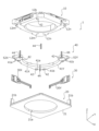
図4、図5は、レンズ駆動装置1の分解斜視図である。図5は、図4をZ軸周りに90°回転させて下方から見た状態を示す。
図4、図5に示すように、本実施の形態において、レンズ駆動装置1は、OIS可動部10(第2可動部)、OIS固定部20(第2固定部)、OIS駆動部30(XY方向駆動部)及びOIS支持部40(第2支持部)等を備える。
4 and 5 are exploded perspective views of the
As shown in FIGS. 4 and 5, in the present embodiment, the
OIS可動部10は、振れ補正時に光軸直交面内で揺動する部分である。OIS可動部10は、AF可動部11(第1可動部)、第1ステージ12(第1固定部)、AF駆動部13(Z方向駆動部)、AF支持部14(第1支持部)及び回転スペーサー15を有するAFユニットを含む(図7等参照)。
OIS固定部20は、OIS支持部40を介してOIS可動部10が接続される部分である。OIS固定部20は、ベース21を含む。
OIS支持部40は、OIS固定部20に対して、OIS可動部10を光軸方向に離間した状態で支持する。OIS支持部40は、第2ステージ41X、41Y、ボール42、43及びOIS用付勢部材44を含む。
OIS可動部10は、OIS固定部20に対して光軸方向に離間して配置され、OIS支持部40を介してOIS固定部20と連結される。また、OIS可動部10とOIS固定部20は、OIS可動部10の外周面の4箇所に配置されたOIS用付勢部材44によって、互いに近づく方向に付勢されている。
本実施の形態では、OIS支持部40を構成するボール42、43(計11個)の転動可能な方向を規制することにより、OIS可動部10をXY面内で精度よく揺動できるようになっている。なお、OIS支持部40を構成するボール42、43の数は、適宜変更することができる。
The OIS
The OIS fixed
The
The OIS
In the present embodiment, by restricting the rolling directions of the
ベース21は、例えば、ポリアリレート(PAR)、PARを含む複数の樹脂材料を混合したPARアロイ(例えば、PAR/PC)、又は液晶ポリマー(LCP:Liquid Crystal Polymer)からなる成形材料で形成された、平面視で矩形状の部材であり、中央に円形の開口21aを有する。
ベース21は、2つの角部に、OIS駆動部30が配置されるOISモーター固定部21bを有する。OISモーター固定部21bは、ベース21の主面から光軸方向受光側に向けて突出して形成され、OIS駆動部30を保持可能な形状を有している。
The
The
図示を省略するが、ベース21には、例えば、インサート成形により、端子金具及び配線が配置されている。また、ベース21には、ホール素子51X、51Yが実装されたセンサー基板が配置されている。
配線は、AF駆動部13(図7等参照)及びOIS駆動部30への給電ラインを含む。配線は、例えば、ベース21の周縁部から露出し、センサー基板に形成された配線及びOIS用付勢部材44と電気的に接続される。
Although not shown, terminal fittings and wiring are arranged on the
The wiring includes a power supply line to the AF driving section 13 (see FIG. 7 and the like) and the
また、ベース21は、ボール42を収容するボール収容部21c、21d、21eを有する。ボール収容部21cは、円形状に凹んで形成されており、ベース21と第1ステージ12との間に介在するボール42を収容する。ボール収容部21dは、X方向に延びる矩形状に凹んで形成されており、ベース21と第2ステージ41Xとの間に介在するボール42を収容する。ボール収容部21eは、Y方向に延びる矩形状に凹んで形成されており、ベース21と第2ステージ41Yとの間に介在するボール42を収容する。ボール収容部21d、21eの側面は、例えば、底面側に向けて溝幅が狭くなるようにテーパー形状に形成される。
The base 21 also has
センサー基板(図示略)は、ホール素子51X、51Y用の給電ライン及び信号ラインを含む配線(図示略)を有する。ホール素子51X、51Yは、センサー基板に形成された配線(図示略)を介して、ベース21の配線(図示略)と電気的に接続される。第2ステージ41X、41Yにおいて、ホール素子51X、51Yに対向する位置にはマグネット52X、52Yが配置されている。ホール素子51X、51Y及びマグネット52X、52YからなるXY位置検出部により、OIS可動部10のX方向及びY方向の位置が検出される。
The sensor substrate (not shown) has wiring (not shown) including power supply lines and signal lines for the
第2ステージ41X、41Yは、例えば、液晶ポリマーで形成され、全体としてL字形状を呈する。第2ステージ41X、41Yの内周面は、レンズホルダー11の外形に沿って円弧状に形成されている。第2ステージ41X、41Yは、それぞれ、X方向、Y方向に沿って配置されている。また、第2ステージ41X、41Yが互いに独立して移動できるように、それぞれの近接する部分は、所定の間隔で離間している。
第2ステージ41X、41Yの外側面は、内側に凹んで形成されており、レンズ駆動装置1を組み立てたときに、OIS駆動部30X、30Yが位置するようになっている。本実施の形態では、第2ステージ41X、41Yを全体としてL字形状に形成するとともに、第1ステージ12において、薄肉に形成された部分の下方に第2ステージ41X、41Yを配置することにより、OIS可動部10の低背化が図られている。
The
The outer surfaces of the
第2ステージ41X、41Yの周縁には、光軸方向受光側に突出する係合片41e、41fが設けられている。係合片41e、41fには、OIS動力伝達部33の一端部が固定される。また、係合片41e、41fは、第1ステージ12に設けられた係合溝12g、12hに遊嵌される。具体的には、係合片41eと係合溝12gは、少なくとも第1ステージ12がY方向に移動する際にY方向に対向する面同士が当接しない程度に係合し、係合片41fと係合溝12hは、少なくとも第1ステージ12がY方向に移動する際にY方向に対向する面同士が当接しない程度に係合する。すなわち、第1ステージ12がY方向に移動しても第2ステージ41Xは変位せず、第1ステージ12がX方向に移動しても第2ステージ41Yは変位しないようになっている。
それぞれの第2ステージ41X、41Yは、下面(光軸方向結像側の面)に、ボール42を収容する3つのボール収容部41a、41bを有する。ボール収容部41aは、ベース21のボール収容部21d、21eに対向する。ボール収容部41a、41bは、それぞれ、X方向、Y方向に延びる長円形状に凹んで形成されている。また、ボール収容部41a、41bの側面は、底面側に向けて溝幅が狭くなるようにテーパー形状に形成されている。
また、それぞれの第2ステージ41X、41Yは、上面(光軸方向受光側の面)に、ボール43を収容する2つのボール収容部41c、41dを有する。ボール収容部41c、41dは、それぞれ、Y方向、X方向に延びる長円形状に凹んで形成されている。ボール収容部41c、41dの側面は、底面側に向けて溝幅が狭くなるようにテーパー形状に形成されている。
Each of the
Each of the
ボール42は、ベース21のボール収容部21c~21eと、第1ステージ12のボール収容部12b及び第2ステージ41X、41Yのボール収容部41a、41bにより挟持される。特に、ベース21のボール収容部21d、21eと第2ステージ41X、41Yのボール収容部41a、41bとの間において、ボール42は多点接触となっている。したがって、ボール42は、安定してX方向又はY方向に転動する。
また、ボール43は、第2ステージ41X、41Yのボール収容部41c、41dと第1ステージ12の下面により、多点接触で挟持される。したがって、ボール43は、安定してX方向又はY方向に転動する。
The
Also, the
OIS用付勢部材44は、例えば、引張コイルばねで構成され、OIS可動部10とOIS固定部20を連結する。本実施の形態では、OIS用付勢部材44の一端は、ベース21の配線(図示略)に接続され、他端は、第1ステージ12の配線(図示略)に接続されている。OIS用付勢部材44は、OIS可動部10とOIS固定部20を連結したときの引張荷重を受けて、OIS可動部10とOIS固定部20が互いに近づくように作用する。すなわち、OIS可動部10は、OIS用付勢部材44によって、光軸方向に付勢された状態(ベース21に押し付けられた状態)で、XY面内で揺動可能に保持されている。これにより、OIS可動部10をがたつきのない安定した状態で保持することができる。
また、本実施の形態では、OIS用付勢部材44は、AF駆動部13への給電ラインとして機能する。
The
Further, in the present embodiment, the
OIS駆動部30は、OIS可動部10をX方向及びY方向に移動させるアクチュエーターである。具体的には、OIS駆動部30は、OIS可動部10をX方向に移動させる第1のOIS駆動部30X(第1のXY方向駆動部)と、OIS可動部10をY方向に移動させる第2のOIS駆動部30Y(第2のXY方向駆動部)とで構成される。
第1のOIS駆動部30Xは、X方向に沿って延在するように、ベース21のOISモーター固定部21bに固定される。第2のOIS駆動部30Yは、Y方向に沿って延在するように、ベース21のOISモーター固定部21bに固定される。すなわち、第1のOIS駆動部30X及び第2のOIS駆動部30Yは、互いに直交する辺に沿って配置される。
The
The first
OIS駆動部30の構成を図6A、図6Bに示す。図6Aは、OIS駆動部30の各部材を組み付けた状態を示し、図6Bは、OIS駆動部30の各部材を分解した状態を示す。なお、図6A、図6Bは、第2のOIS駆動部30Yを示しているが、第1のOIS駆動部30Xの主要構成は同様であるので、OIS駆動部30を示す図として扱う。
The configuration of the
図6A、図6Bに示すように、OIS駆動部30は、OIS共振部31、OIS圧電素子32、OIS電極(図示略)及びOIS動力伝達部33を有する。OIS共振部31、OIS圧電素子32及びOIS電極(図示略)により超音波モーターが構成され、超音波モーターの駆動力は、OIS動力伝達部33を介して第2ステージ41X、41Yに伝達される。
As shown in FIGS. 6A and 6B , the
OIS圧電素子32は、例えば、セラミック材料で形成された板状素子であり、高周波電圧を印加することにより振動を発生する。
OIS電極(図示略)は、OIS共振部31及びOIS圧電素子32を挟持し、OIS圧電素子32に電圧を印加する。OIS電極は、例えば、ベース21の配線(図示略)と電気的に接続される。
The OIS
OIS electrodes (not shown) sandwich the
OIS共振部31は、導電性材料で形成され、OIS圧電素子32の振動に共振して、振動運動を直線運動に変換する。本実施の形態では、OIS共振部31は、OIS圧電素子32に挟持される略矩形状の胴部31a、胴部31aの上部及び下部から延在する2つのアーム部31b、胴部31aの中央部から突出する突出部31c、及び、胴部31aの中央部から突出部31cとは反対側に延在する通電部31dを有している。通電部31dは、例えば、ベース21の配線と電気的に接続される。2つのアーム部31bは対称的な形状を有し、それぞれの自由端部がOIS動力伝達部33に当接し、OIS圧電素子32の振動に共振して対称的に変形する。
The
OIS共振部31の胴部31aに、厚さ方向からOIS圧電素子32が貼り合わされ、OIS電極(図示略)により挟持されることにより、これらは互いに電気的に接続される。例えば、給電経路の一方がOIS電極に接続され、他方がOIS共振部31の通電部31dに接続されることで、OIS圧電素子32に電圧が印加され、振動が発生する。
The OIS
OIS共振部31は、少なくとも2つの共振周波数を有し、それぞれの共振周波数に対して、異なる挙動で変形する。言い換えると、OIS共振部31は、2つの共振周波数に対して異なる挙動で変形するように、全体の形状が設定されている。異なる挙動とは、OIS動力伝達部33をX方向又はY方向に前進させる挙動と、後退させる挙動である。
The
OIS動力伝達部33は、一方向に延在するチャッキングガイドであり、一端がOIS共振部31に接続され、他端が第2ステージ41X、41Yに接続される。OIS動力伝達部33は、OISモーター当接部33a、ステージ固定部33c、及び連結部33bを有する。OISモーター当接部33aは、例えば、断面略L字状に形成され、OIS共振部31のアーム部31bの自由端部と当接する。ステージ固定部33cは、OIS動力伝達部33の端部に配置され、第2ステージ41X、41Yの係合片41e、41f(図4等参照)に固定される。連結部33bは、OISモーター当接部33aとステージ固定部33cを連結する部分であり、ステージ固定部33cから2つに分岐して互いに平行に形成されている。
The OIS
OISモーター当接部33a間の幅は、OIS共振部31のアーム部31bの自由端部間の幅よりも広く設定される。これにより、OIS共振部31にOIS動力伝達部33を取り付けたときに、OIS動力伝達部33が板バネとして機能し、OIS共振部31のアーム部31bを押し広げる方向に付勢力が作用する。この付勢力により、OIS共振部31のアーム部31bの自由端部間にOIS動力伝達部33が保持され、OIS共振部31からの駆動力がOIS動力伝達部33に効率よく伝達される。
The width between the OIS
OIS共振部31とOIS動力伝達部33は、付勢された状態で当接しているだけなので、当接部分をX方向又はY方向に大きくするだけで、レンズ駆動装置1の外形を大きくすることなく、OIS可動部10の移動距離(ストローク)を長くすることができる。
Since the
第1のOIS駆動部30Xは、ベース21と第2ステージ41Xを連結するように固定されており、第2のOIS駆動部30Xは、ベース21と第2ステージ41Yを連結するように固定されている。
第1のOIS駆動部30XによるX方向の振れ補正時は、第2ステージ41X及び第1ステージ12が移動し、第2ステージ41Yは移動しない。一方、第2のOIS駆動部30YによるY方向の振れ補正時は、第2ステージ41Y及び第1ステージ12が移動し、第2ステージ41Xは移動しない。すなわち、一方のOIS駆動部30によるOIS可動部10の移動は、他方のOIS駆動部30の構造によって妨げられないようになっている。OIS可動部10のZ軸周りの回転を防止することができるので、OIS可動部10をXY平面内で精度よく揺動させることができる。
The first
During shake correction in the X direction by the first
図7、図8は、OIS可動部10の分解斜視図である。図8は、図7をZ軸周りに90°回転させて下方から見た図を示す。なお、図8では、AF駆動部13を回転スペーサー15に取り付けた状態を示している。
図7、図8に示すように、本実施の形態において、OIS可動部10は、AF可動部11、第1ステージ12、AF駆動部13、AF支持部14及び回転スペーサー15等を有する。
7 and 8 are exploded perspective views of the OIS
As shown in FIGS. 7 and 8, in the present embodiment, the OIS
AF可動部11は、ピント合わせ時に光軸方向に移動する部分である。AF可動部11は、第1ステージ12(第1固定部)に対して径方向に離間して配置され、AF支持部14を介して第1ステージ12と接続される。
The AF
AF可動部11は、レンズ部2(図2参照)を保持するレンズホルダーで構成される(以下、「レンズホルダー11」と称する)。レンズホルダー11は、例えば、ポリアリレート(PAR)、PARを含む複数の樹脂材料を混合したPARアロイ、液晶ポリマー等で形成される。レンズホルダー11は、筒状のレンズ収容部11aを有する。レンズ収容部11aには、レンズ部2(図2参照)が、例えば、接着により固定される。
The AF
レンズホルダー11は、レンズ収容部11aの上部外周縁に、径方向外側に突出するスライド部11bを有する。スライド部11bの下面11cは、光軸方向に傾斜して形成されており、回転スペーサー15の回転に連動してスライド部11bが光軸方向結像側にせり上がり、レンズホルダー11が光軸方向に移動するようになっている。
The
第1ステージ12は、AF支持部14を介してレンズホルダー11を支持する部分である。第1ステージ12の下方には、ボール43を介して第2ステージ41X、41Yが配置される。第1ステージ12は、振れ補正時に、第2ステージ41X、41Yの移動に連動して、X方向及びY方向に移動する。
The
第1ステージ12は、略矩形筒状の部材であり、例えば、液晶ポリマーで形成される。第1ステージ12は、レンズホルダー11に対応する部分に略円形状の開口12aを有する。第1ステージ12において、第2ステージ41X、41Yに対応する部分は、他の部分に比較して、第2ステージ41X、41Yの厚み分だけ薄肉に形成されている。
The
第1ステージ12は、下面に、ベース21との間に介在する42を収容するボール収容部12bを有する。ボール収容部12bは、ベース21のボール収容部21eとZ方向において対向する位置に、円形状に凹んで形成されている。また、第1ステージ12は、下面に、第2ステージ41X、41Yとの間に介在するボール43を収容するボール収容部12m、12nを有する。ボール収容部12m、12nは、それぞれ、第2ステージ41X、41Yのボール収容部41c、41dとZ方向において対向する位置に、Y方向、X方向に延びる長円形状に凹んで形成されている。ボール収容部12m、12nの側面は、底面側に向けて溝幅が狭くなるようにテーパー形状に形成されている。
第1ステージ12は、上面の4隅に、AF支持部14を固定する上バネ固定部12cを有する。上バネ固定部12cは、主面12jよりも光軸方向受光側に突出して形成されている。
The
The
第1ステージ12は、開口12aの周縁部に、スペーサー配置部12d及びモーター固定部12fを有する。スペーサー配置部12dは、主面12jよりも光軸方向結像側に凹んで形成されており、ボール17を収容するボール収容部12eを有している。スペーサー配置部12dと主面12jとの段差によって、回転スペーサー15の回転が規制される。モーター固定部12fには、AF駆動部13が固定される。
The
本実施の形態では、3つのスペーサー配置部12dが、周方向に沿って等間隔で設けられている。これにより、回転スペーサー15の姿勢が安定するので、回転動作を精度良く制御することができる。なお、スペーサー配置部12dは、2又は4以上設けられてもよい。
In this embodiment, three
図示を省略するが、第1ステージ12には、例えば、インサート成形により、配線が配置されている。配線は、適宜、第1ステージ12から露出しており、この部分に、AF駆動部13及びOIS用付勢部材44と電気的に接続される。AF駆動部13には、OIS用付勢部材44及び第1ステージ12の配線を介して給電が行われる。
Although not shown, wiring is arranged on the
また、第1ステージ12のX方向に沿う一方の側面及びY方向に沿う一方の側面において、第2ステージ41X、41Yの係合片41e、41fと対応する位置には、係合溝12g、12hが設けられている。レンズ駆動装置1を組み立てた状態において、第2ステージ41X、41Yの係合片41e、41fは、第1ステージ12の係合溝12g、12hと係合する。これにより、OIS可動部10(第1ステージ12)は、第2ステージ41X、41Yの移動に連動して、X方向又はY方向に移動する。
AF支持部14は、第1ステージ12に対して、レンズホルダー11を光軸方向に移動可能に支持する。本実施の形態では、AF支持部14は、第1ステージ12に対してレンズホルダー11を光軸方向受光側(上側)で弾性的に支持する上バネで構成されている(以下、「上バネ14」と称する)。上バネ14は、例えば、ベリリウム銅、ニッケル銅、ステンレス等の金属材料からなる板バネである。
The
上バネ14は、レンズホルダー固定部14a、ステージ固定部14b、及びアーム部14cを有する。レンズホルダー固定部14aは、レンズホルダー11のレンズ収容部11aの上面に対応する形状を有する。ステージ固定部14bは、第1ステージ12の上バネ固定部12cに対応する位置に設けられる。アーム部14cは、レンズホルダー固定部14aから延在し、レンズホルダー固定部14aとステージ固定部14bを連結する。
The
上バネ14は、例えば、レンズホルダー固定部14aに設けられた位置決め片14dが、レンズホルダー11のスライド部11bに設けられた位置決め孔11dに係合されることにより、レンズホルダー11に対して位置決めされ、固定される。また、上バネ14は、例えば、ステージ固定部14bが第1ステージ12の上バネ固定部12cに接着されることにより、第1ステージ12に対して固定される。レンズホルダー11が光軸方向に移動するとき、レンズホルダー固定部14aはレンズホルダー11とともに変位し、アーム部14cは弾性的に変形する。
The
回転スペーサー15は、AF駆動部13の直線運動を受けて光軸を中心に回転する回転体である。回転スペーサー15は、円環形状を有し、レンズホルダー11の外周面に沿って配置される。また、回転スペーサー15は、AF駆動部13が接続されるモーター接続部15dを有する。
The rotating
回転スペーサー15は、円環部15a及びステージ固定部15bを有する。ステージ固定部15bは、第1ステージ12のスペーサー配置部12dに対応する位置に設けられ、例えば、円環部15aから光軸方向結像側に突出して形成される。ステージ固定部15bの上面15cは、光軸方向に傾斜して形成されており、レンズホルダー11のスライド部11bが載置される(以下、「ホルダー案内部15c」と称する)。
The rotating
回転スペーサー15のホルダー案内部15cとレンズホルダー11のスライド部11bは、回転スペーサー15の回転に伴って、ホルダー案内部15cに沿ってスライド部11bが摺動する端面カム18(図10A等参照)を構成する。端面カム18は、回転運動を光軸方向の直線運動に変換する機械要素である。
The
本実施の形態では、3つの端面カム18が、周方向に沿って等間隔で設けられている。これにより、回転スペーサー15の回転運動が端面カム18によって直線運動に変換され、レンズホルダー11に均等に伝達されるので、レンズホルダー11の移動動作を精度良く制御することができる。なお、端面カム18は、周方向に沿って等間隔で2つ又は4つ以上設けられてもよい。
In this embodiment, three
本実施の形態では、ホルダー案内部15cとスライド部11bの間にはボール16が配置され、両者は間接的に当接しており、回転スペーサー15とレンズホルダー11が滑らかに摺動するようになっている。なお、回転スペーサー15とレンズホルダー11との間にボール16を配置せず、両者が直接的に当接し、摺動するようにしてもよい。
また、回転スペーサー15と第1ステージ12の間には、ボール17が配置され、第1ステージ12上で回転スペーサー15が滑らかに回転するようになっている。
In this embodiment, the
A
AF駆動部13は、レンズホルダー11をZ方向に移動させるアクチュエーターである。AF駆動部13は、OIS駆動部30と同様に、超音波モーターで構成されている。AF駆動部13は、回転スペーサー15の周面に沿うように、第1ステージ12のモーター固定部12fに固定される。
The
AF駆動部13の構成を図9に示す。
図9に示すように、AF駆動部13は、AF共振部131、AF圧電素子132、AF電極(図示略)及びAF動力伝達部133を有する。AF共振部131、AF圧電素子132及びAF電極(図示略)により超音波モーターが構成され、超音波モーターの駆動力は、AF動力伝達部133を介して回転スペーサー15に伝達される。
FIG. 9 shows the configuration of the
As shown in FIG. 9 , the
AF圧電素子132は、例えば、セラミック材料で形成された板状素子であり、高周波電圧を印加することにより振動を発生する。
AF電極(図示略)は、AF共振部131及びAF圧電素子132を挟持し、AF圧電素子132に電圧を印加する。AF電極は、例えば、第1ステージ12の配線(図示略)と電気的に接続される。
The AF
AF electrodes (not shown) sandwich the
AF共振部131は、導電性材料で形成され、AF圧電素子132の振動に共振して、振動運動を直線運動に変換する。本実施の形態では、AF共振部131は、AF圧電素子132に挟持される略矩形状の胴部131a、胴部131aの上部及び下部から延在する2つのアーム部131b、胴部131aの中央部から突出する突出部131c、及び、胴部131aの中央部から突出部131cとは反対側に延在し給電経路(第1ステージ12の配線)と電気的に接続される通電部131dを有している。2つのアーム部131bは対称的な形状を有し、それぞれの自由端部がAF動力伝達部133に当接し、AF圧電素子132の振動に共振して対称的に変形する。
The
AF共振部131の胴部131aに、厚さ方向からAF圧電素子132が貼り合わされ、AF電極(図示略)により挟持されることにより、これらは互いに電気的に接続される。例えば、AF共振部131の通電部131d及びAF電極が、第1ステージ12の配線(図示略)に接続されることで、AF圧電素子132に電圧が印加され、振動が発生する。
The AF
AF共振部131は、OIS共振部31と同様に、少なくとも2つの共振周波数を有し、それぞれの共振周波数に対して、異なる挙動で変形する。言い換えると、AF共振部131は、2つの共振周波数に対して異なる挙動で変形するように、全体の形状が設定されている。異なる挙動とは、AF動力伝達部133を、周方向に沿って前進させる挙動と、後退させる挙動である。
The
AF動力伝達部133は、周方向に沿って延在するチャッキングガイドであり、一端がAF共振部131に接続され、他端が回転スペーサー15に接続される。AF動力伝達部133は、AFモーター当接部133a、スペーサー固定部133c、及び連結部133bを有する。AFモーター当接部133aは、例えば、平板状に形成され、AF共振部131のアーム部131bの自由端部と当接する。スペーサー固定部133cは、AF動力伝達部133の端部に配置され、回転スペーサー15のモーター接続部15dに固定される。連結部133bは、AFモーター当接部133aとスペーサー固定部133cを連結する部分であり、スペーサー固定部133cから2つに分岐して互いに平行に、かつ収容方向に沿うように湾曲して形成されている。
The AF
AF動力伝達部133は、AF共振部131の直線運動を受けて運動をするが、AF動力伝達部133の一端は回転スペーサー15に接続されて拘束されているので、AF共振部131のアーム部131bとAF動力伝達部133のAFモーター当接部133aが摺動し、AF動力伝達部133は回転することとなる。つまり、AF駆動部13は、AF動力伝達部133を含めると、振動運動を回転運動に変換しているといえる。
The AF
AFモーター当接部133a間の幅は、AF共振部131のアーム部131bの自由端部間の幅よりも広く設定される。これにより、AF共振部131にAF動力伝達部133を取り付けたときに、AF動力伝達部133が板バネとして機能し、AF共振部131のアーム部131bを押し広げる方向に付勢力が作用する。この付勢力により、AF共振部131のアーム部131bの自由端部間にAF動力伝達部133が保持され、AF共振部131からの駆動力がAF動力伝達部133に効率よく伝達される。
The width between the AF
AF共振部131とAF動力伝達部133は、付勢された状態で当接しているだけなので、当接部分を周方向に沿って大きくするだけで、レンズ駆動装置1の外形を大きくすることなく、回転スペーサー15の回転量、すなわち、レンズホルダー11の移動距離(光軸方向のストローク)を長くすることができる。
Since the
レンズ駆動装置1において、AF駆動部13に電圧を印加すると、AF圧電素子132が振動し、AF共振部131が周波数に応じた挙動で変形する。AF駆動部13の駆動力により、回転スペーサー15が回転し、レンズホルダー11が光軸方向に移動して、ピント合わせが行われる。
In the
回転スペーサー15の回転に伴うレンズホルダー11の挙動の具体例を図10A、図10Bに示す。図10Aは、AF駆動部13が駆動されていない初期状態を示し、図10Bは、AF駆動部13が駆動されている状態を示す。
図10A、図10Bに示すように、AF駆動部13が駆動され、AF動力伝達部133がAF共振部131側に引き込まれると、AF動力伝達部133に接続されている回転スペーサー15が回転する。これに伴い、端面カム18が動作し、回転スペーサー15のホルダー案内部15cに沿ってレンズホルダー11のスライド部11bがせり上がり、レンズホルダー11が光軸方向受光側に移動する。
A specific example of the behavior of the
As shown in FIGS. 10A and 10B, when the
レンズ駆動装置1において、OIS駆動部30に電圧を印加すると、OIS圧電素子32が振動し、OIS共振部31が周波数に応じた挙動で変形する。OIS駆動部30の駆動力により、OIS動力伝達部33がX方向又はY方向に摺動される。これに伴い、OIS可動部10がX方向又はY方向に移動し、振れ補正が行われる。
In the
具体的には、第1のOIS駆動部30Xが駆動され、OIS動力伝達部33がX方向に移動する場合、第1のOIS駆動部30Xが配置されているベース21から第2ステージ41Xに動力が伝達される。第2ステージ41Xとベース21とで挟持されているボール42(ボール収容部21dに配置されているボール42)は、X方向に転動可能に配置されているので、ベース21に対して第2ステージ41XはX方向に移動する。第1ステージ12と第2ステージ41Xで挟持されているボール43(ボール収容部41cに配置されているボール43)はX方向に転動できないので、第2ステージ41Xに対して第1ステージ12のX方向の位置は維持され、第1ステージ12は第2ステージ41Xに連動してX方向に移動する。
このとき、第2ステージ41Yと第1ステージ12とで挟持されているボール43(ボール収容部41dに配置されているボール43)はX方向に転動可能に配置されているので、第1ステージ12は、第2ステージ41Y上をスムーズに摺動する。また、第2ステージ41Yとベース21とで挟持されているボール42(ボール収容部21eに配置されているボール42)によって、ベース21に対する第2ステージ41YのX方向への移動は規制されている。
したがって、ベース21に対して第2ステージ41Yは変位せず、第2ステージ41Xと第1ステージ12だけがX方向に移動する。
Specifically, when the first
At this time, the
Therefore, the
同様に、第2のOIS駆動部30Yが駆動され、OIS動力伝達部33がY方向に移動する場合、第2のOIS駆動部30Yが配置されているベース21から第2ステージ41Yに動力が伝達される。第2ステージ41Yとベース21とで挟持されているボール42(ボール収容部21eに配置されているボール42)は、Y方向に転動可能に配置されているので、ベース21に対して第2ステージ41YはY方向に移動する。第1ステージ12と第2ステージ41Yで挟持されているボール43(ボール収容部41dに配置されているボール43)はY方向に転動できないので、第2ステージ41Yに対して第1ステージ12のY方向の位置は維持され、第1ステージ12は第2ステージ41Yに連動してY方向に移動する。
このとき、第2ステージ41Xと第1ステージ12とで挟持されているボール43(ボール収容部41cに配置されているボール43)はY方向に転動可能に配置されているので、第1ステージ12は、第2ステージ41X上をスムーズに摺動する。また、第2ステージ41Xとベース21とで挟持されているボール42(ボール収容部21dに配置されているボール42)によって、ベース21に対する第2ステージ41XのY方向への移動は規制されている。
したがって、ベース21に対して第2ステージ41Xは変位せず、第2ステージ41Yと第1ステージ12だけがY方向に移動する。
Similarly, when the second
At this time, since the
Therefore, the
このように、第2ステージ41X、41Yは、互いに干渉せず、それぞれ独立して移動可能となっている。つまり、第2ステージ41Xに接続されている第1のOIS駆動部30Xは、第2ステージ41Yの移動によってY方向の力を受けることはなく、第2ステージ41Yに接続されている第2のOIS駆動部30Yは、第2ステージ41Xの移動によってX方向の力を受けることはない。したがって、精度よくXY面内における振れ補正を行うことができる。
Thus, the
このようにして、OIS可動部10がXY平面内で揺動し、振れ補正が行われる。具体的には、カメラモジュールAの角度振れが相殺されるように、振れ検出部(例えばジャイロセンサー、図示略)からの角度振れを示す検出信号に基づいて、OIS駆動部30への通電電圧が制御される。このとき、マグネット52X、52Y及びホール素子51X、51Yで構成されるXY位置検出部の検出結果をフィードバックすることで、OIS可動部10の並進移動を正確に制御することができる。
In this manner, the OIS
このように、実施の形態に係るレンズ駆動装置1は、第1ステージ12(第1固定部)と、レンズ部2を保持し、第1ステージ12と離間して配置されるレンズホルダー11(第1可動部)と、第1ステージ12に対してレンズホルダー11を支持するAF支持部14(第1支持部)と、振動運動を直線運動に変換する超音波モーターで構成され、第1ステージ12に対してレンズホルダー11を光軸方向(Z方向)に移動させるAF駆動部13(Z方向駆動部)と、を備える。レンズ駆動装置1は、AF駆動部13の直線運動を受けて光軸を中心に回転する回転スペーサー15(回転体)と、回転スペーサー15の回転運動を光軸方向の直線運動に変換する端面カム18(機械要素)と、を有し、回転スペーサー15が回転することにより、レンズホルダー11が光軸方向に移動する。
As described above, the
レンズ駆動装置1によれば、AF駆動部13が超音波モーターで構成されているので、外部磁気の影響を低減できるとともに、小型化及び低背化を図ることができる。したがって、スマートフォンMのように、レンズ駆動装置1を有するカメラモジュールAを近接して配置しても磁気的な影響はないので、デュアルカメラ用として極めて好適である。
According to the
以上、本発明者によってなされた発明を実施の形態に基づいて具体的に説明したが、本発明は上記実施の形態に限定されるものではなく、その要旨を逸脱しない範囲で変更可能である。 Although the invention made by the inventor of the present invention has been specifically described above based on the embodiments, the present invention is not limited to the above embodiments, and can be changed without departing from the scope of the invention.
例えば、実施の形態では、カメラモジュールAを備えるカメラ搭載装置の一例として、カメラ付き携帯端末であるスマートフォンMを挙げて説明したが、本発明は、カメラモジュールとカメラモジュールで得られた画像情報を処理する画像処理部を有するカメラ搭載装置に適用できる。カメラ搭載装置は、情報機器及び輸送機器を含む。情報機器は、例えば、カメラ付き携帯電話機、ノート型パソコン、タブレット端末、携帯型ゲーム機、webカメラ、カメラ付き車載装置(例えば、バックモニター装置、ドライブレコーダー装置)を含む。また、輸送機器は、例えば自動車を含む。 For example, in the embodiments, the smart phone M, which is a mobile terminal with a camera, was described as an example of a camera-equipped device equipped with a camera module A. It can be applied to a camera-equipped device having an image processing unit for processing. Camera-equipped devices include information equipment and transportation equipment. Information devices include, for example, camera-equipped mobile phones, laptop computers, tablet terminals, portable game machines, web cameras, and camera-equipped in-vehicle devices (eg, back monitor devices, drive recorder devices). Transportation equipment also includes, for example, automobiles.
図11A、図11Bは、車載用カメラモジュールVC(Vehicle Camera)を搭載するカメラ搭載装置としての自動車Vを示す図である。図11Aは自動車Vの正面図であり、図11Bは自動車Vの後方斜視図である。自動車Vは、車載用カメラモジュールVCとして、実施の形態で説明したカメラモジュールAを搭載する。図11A、図11Bに示すように、車載用カメラモジュールVCは、例えば前方に向けてフロントガラスに取り付けられたり、後方に向けてリアゲートに取り付けられたりする。この車載用カメラモジュールVCは、バックモニター用、ドライブレコーダー用、衝突回避制御用、自動運転制御用等として使用される。 11A and 11B are diagrams showing an automobile V as a camera-equipped device equipped with an in-vehicle camera module VC (Vehicle Camera). 11A is a front view of automobile V, and FIG. 11B is a rear perspective view of automobile V. FIG. An automobile V is equipped with the camera module A described in the embodiment as an in-vehicle camera module VC. As shown in FIGS. 11A and 11B, the in-vehicle camera module VC is attached to the windshield facing forward, or attached to the rear gate facing rearward, for example. This in-vehicle camera module VC is used for a back monitor, drive recorder, collision avoidance control, automatic driving control, and the like.
また、実施の形態では、レンズホルダー11のスライド部11bと回転スペーサー15のホルダー案内部15cとで構成される端面カム18を利用しているが、レンズホルダー11と回転スペーサー15の間に介在する機械要素には、その他のカム構造等を適用してもよい。
In the embodiment, the
また、実施の形態では、AF駆動部13により回転スペーサー15を回転させ、端面カム18により回転運動を直線運動に変換してレンズホルダー11を光軸方向に移動させているが、レンズホルダー11を回転させながら光軸方向に移動させる、すなわち、レンズホルダー11を回転体として機能させ、螺旋運動させるようにしてもよい。この場合、レンズホルダー11と第1ステージ12の間に機械要素が設けられる。
In the embodiment, the rotating
また、本発明は、オートフォーカスだけでなく、ズームなど、第1可動部(レンズホルダー11)を光軸方向に移動させる場合に適用することができる。 Moreover, the present invention can be applied not only to autofocusing but also to zooming, etc., in which the first movable portion (lens holder 11) is moved in the optical axis direction.
今回開示された実施の形態はすべての点で例示であって制限的なものではないと考えられるべきである。本発明の範囲は上記した説明ではなくて特許請求の範囲によって示され、特許請求の範囲と均等の意味および範囲内でのすべての変更が含まれることが意図される。 It should be considered that the embodiments disclosed this time are illustrative in all respects and not restrictive. The scope of the present invention is indicated by the scope of the claims rather than the above description, and is intended to include all modifications within the scope and meaning of equivalents of the scope of the claims.
1 レンズ駆動装置
10 OIS可動部(第2可動部)
11 AF可動部、レンズホルダー(第1可動部)
11b スライド部
12 第1ステージ(第1固定部)
13 AF駆動部(Z方向駆動部)
14 AF支持部、上バネ(第1支持部)
15 回転スペーサー
15c ホルダー案内部
16、17 ボール
18 端面カム(機械要素)
20 OIS固定部(第2固定部)
30 OIS駆動部(XY方向駆動部)
40 OIS支持部(第2支持部)
1
11 AF movable part, lens holder (first movable part)
13 AF drive unit (Z-direction drive unit)
14 AF support, upper spring (first support)
15
20 OIS fixing part (second fixing part)
30 OIS drive unit (XY direction drive unit)
40 OIS support (second support)
Claims (5)
前記レンズホルダーの外周に配置されたリング状の回転体と、
前記回転体の回転を前記レンズホルダーの光軸方向の移動に変換する機械要素と、
板状の圧電素子と、板状の共振部と、湾曲形状の動力伝達部と、を有し、前記圧電素子及び前記共振部が、互いの板面を貼り合わせた状態で前記回転体の外周に対向して配置され、前記動力伝達部が、前記湾曲形状を前記回転体の外周に沿わせた状態で前記回転体の外周に対向して配置され、前記動力伝達部の周方向両端が、前記共振部及び前記回転体に接続された、超音波モーターと、を有し、
前記圧電素子の振動を、前記振動に共振する前記共振部の直線運動により前記動力伝達部を前記周方向に移動させることで回転運動に変換して、前記レンズホルダーを前記光軸方向に移動させる、
レンズ駆動装置。 a lens holder that supports the lens;
a ring-shaped rotating body arranged on the outer periphery of the lens holder;
a mechanical element that converts rotation of the rotating body into movement of the lens holder in the optical axis direction;
A plate-shaped piezoelectric element, a plate-shaped resonance section, and a curved power transmission section are provided, and the piezoelectric element and the resonance section are attached to the outer periphery of the rotating body while the plate surfaces of the piezoelectric element and the resonance section are bonded to each other. and the power transmission section is arranged to face the outer periphery of the rotating body with the curved shape along the outer periphery of the rotating body, and both ends of the power transmitting section in the circumferential direction are: an ultrasonic motor connected to the resonator and the rotating body ;
The vibration of the piezoelectric element is converted into rotary motion by moving the power transmission unit in the circumferential direction by the linear motion of the resonance unit that resonates with the vibration, thereby moving the lens holder in the optical axis direction. ,
lens drive.
請求項1に記載のレンズ駆動装置。 The ultrasonic motor has a configuration in which the stroke of the lens holder in the optical axis direction is lengthened by lengthening the contact portion of the power transmission section that contacts the resonance section in the circumferential direction.
The lens driving device according to claim 1.
請求項1に記載のレンズ駆動装置。 In the ultrasonic motor, the length in the circumferential direction of the contact portion of the power transmission portion that is in contact with the resonance portion is a length corresponding to the stroke of the lens holder in the optical axis direction.
The lens driving device according to claim 1.
前記レンズと、
前記レンズにより結像された被写体像を撮像する撮像部と、を備える、
カメラモジュール。 A lens driving device according to any one of claims 1 to 3;
the lens;
an imaging unit that captures a subject image formed by the lens,
The camera module.
請求項4に記載のカメラモジュールと、
前記カメラモジュールで得られた画像情報を処理する画像処理部と、を備える、
カメラ搭載装置。 A camera-equipped device that is information equipment or transportation equipment,
a camera module according to claim 4;
an image processing unit that processes image information obtained by the camera module;
Device with camera.
Priority Applications (6)
| Application Number | Priority Date | Filing Date | Title |
|---|---|---|---|
| JP2019107368A JP7294897B2 (en) | 2019-06-07 | 2019-06-07 | LENS DRIVING DEVICE, CAMERA MODULE, AND CAMERA MOUNTING DEVICE |
| PCT/JP2020/021770 WO2020246465A1 (en) | 2019-06-07 | 2020-06-02 | Lens drive device, camera module, and camera-equipped device |
| CN202080041688.1A CN113924516A (en) | 2019-06-07 | 2020-06-02 | Lens driving device, camera module, and camera mounting device |
| US17/616,710 US20220308303A1 (en) | 2019-06-07 | 2020-06-02 | Lens driving apparatus, camera module and camera-mounted apparatus |
| KR1020217037553A KR20220017398A (en) | 2019-06-07 | 2020-06-02 | Lens drive device, camera module, and camera mounting device |
| JP2023094828A JP2023105217A (en) | 2019-06-07 | 2023-06-08 | Rotation drive device |
Applications Claiming Priority (1)
| Application Number | Priority Date | Filing Date | Title |
|---|---|---|---|
| JP2019107368A JP7294897B2 (en) | 2019-06-07 | 2019-06-07 | LENS DRIVING DEVICE, CAMERA MODULE, AND CAMERA MOUNTING DEVICE |
Related Child Applications (1)
| Application Number | Title | Priority Date | Filing Date |
|---|---|---|---|
| JP2023094828A Division JP2023105217A (en) | 2019-06-07 | 2023-06-08 | Rotation drive device |
Publications (3)
| Publication Number | Publication Date |
|---|---|
| JP2020201359A JP2020201359A (en) | 2020-12-17 |
| JP2020201359A5 JP2020201359A5 (en) | 2022-03-07 |
| JP7294897B2 true JP7294897B2 (en) | 2023-06-20 |
Family
ID=73653229
Family Applications (2)
| Application Number | Title | Priority Date | Filing Date |
|---|---|---|---|
| JP2019107368A Active JP7294897B2 (en) | 2019-06-07 | 2019-06-07 | LENS DRIVING DEVICE, CAMERA MODULE, AND CAMERA MOUNTING DEVICE |
| JP2023094828A Pending JP2023105217A (en) | 2019-06-07 | 2023-06-08 | Rotation drive device |
Family Applications After (1)
| Application Number | Title | Priority Date | Filing Date |
|---|---|---|---|
| JP2023094828A Pending JP2023105217A (en) | 2019-06-07 | 2023-06-08 | Rotation drive device |
Country Status (5)
| Country | Link |
|---|---|
| US (1) | US20220308303A1 (en) |
| JP (2) | JP7294897B2 (en) |
| KR (1) | KR20220017398A (en) |
| CN (1) | CN113924516A (en) |
| WO (1) | WO2020246465A1 (en) |
Families Citing this family (3)
| Publication number | Priority date | Publication date | Assignee | Title |
|---|---|---|---|---|
| US20230224585A1 (en) * | 2020-03-30 | 2023-07-13 | Mitsumi Electric Co., Ltd. | Optical-element driving device, camera module and camera-mounted device |
| WO2022158089A1 (en) * | 2021-01-19 | 2022-07-28 | 株式会社村田製作所 | Camera module |
| CN115918100A (en) * | 2021-04-14 | 2023-04-04 | 北京小米移动软件有限公司 | Camera actuator |
Citations (3)
| Publication number | Priority date | Publication date | Assignee | Title |
|---|---|---|---|---|
| JP2006017923A (en) | 2004-06-30 | 2006-01-19 | Mitsumi Electric Co Ltd | Miniature camera |
| JP2008503995A (en) | 2004-06-24 | 2008-02-07 | ミニスイス・ソシエテ・アノニム | Drive device |
| WO2020036157A1 (en) | 2018-08-13 | 2020-02-20 | Miniswys S.A. | Lens driving device, camera module, and camera-mounted device |
Family Cites Families (13)
| Publication number | Priority date | Publication date | Assignee | Title |
|---|---|---|---|---|
| JPS6090408U (en) * | 1983-11-25 | 1985-06-20 | 日本電産コパル株式会社 | lens drive mechanism |
| JP4213555B2 (en) * | 2003-10-15 | 2009-01-21 | セイコーインスツル株式会社 | Piezoelectric actuator and electronic device using the same |
| KR100573576B1 (en) * | 2005-06-03 | 2006-04-24 | 주식회사 세코닉스 | Lens assembly for a mobile phone equipped with macro function |
| JP2008089803A (en) * | 2006-09-29 | 2008-04-17 | Fujinon Corp | Imaging apparatus |
| JP2008167561A (en) * | 2006-12-27 | 2008-07-17 | Kyocera Corp | Drive mechanism employing piezoelectric element and camera module employing the drive mechanism, and portable terminal with the camera module |
| JP2009136050A (en) * | 2007-11-29 | 2009-06-18 | Nidec Copal Corp | Drive device |
| JP2009258497A (en) * | 2008-04-18 | 2009-11-05 | Minebea Co Ltd | Lens driving actuator |
| CH699707A2 (en) * | 2008-10-10 | 2010-04-15 | Creaholic Sa | Miniaturised powered storage device. |
| JP2011215350A (en) * | 2010-03-31 | 2011-10-27 | Fujifilm Corp | Lens assembly and camera unit |
| JP5849830B2 (en) | 2012-03-30 | 2016-02-03 | ミツミ電機株式会社 | Lens holder driving device, camera module, and portable terminal with camera |
| CN104678532B (en) * | 2013-12-03 | 2017-08-08 | 博立码杰通讯(深圳)有限公司 | Zoom focusing mechanism and zoom lens |
| CH709292A3 (en) | 2014-02-20 | 2015-10-15 | Miniswys Sa | Positioning device for an image stabilizer. |
| CN208459665U (en) * | 2018-07-06 | 2019-02-01 | 中山联合光电科技股份有限公司 | The zoom lens of Driven by Ultrasonic Motors |
-
2019
- 2019-06-07 JP JP2019107368A patent/JP7294897B2/en active Active
-
2020
- 2020-06-02 KR KR1020217037553A patent/KR20220017398A/en unknown
- 2020-06-02 CN CN202080041688.1A patent/CN113924516A/en active Pending
- 2020-06-02 WO PCT/JP2020/021770 patent/WO2020246465A1/en active Application Filing
- 2020-06-02 US US17/616,710 patent/US20220308303A1/en active Pending
-
2023
- 2023-06-08 JP JP2023094828A patent/JP2023105217A/en active Pending
Patent Citations (3)
| Publication number | Priority date | Publication date | Assignee | Title |
|---|---|---|---|---|
| JP2008503995A (en) | 2004-06-24 | 2008-02-07 | ミニスイス・ソシエテ・アノニム | Drive device |
| JP2006017923A (en) | 2004-06-30 | 2006-01-19 | Mitsumi Electric Co Ltd | Miniature camera |
| WO2020036157A1 (en) | 2018-08-13 | 2020-02-20 | Miniswys S.A. | Lens driving device, camera module, and camera-mounted device |
Also Published As
| Publication number | Publication date |
|---|---|
| US20220308303A1 (en) | 2022-09-29 |
| WO2020246465A1 (en) | 2020-12-10 |
| KR20220017398A (en) | 2022-02-11 |
| JP2023105217A (en) | 2023-07-28 |
| CN113924516A (en) | 2022-01-11 |
| JP2020201359A (en) | 2020-12-17 |
Similar Documents
| Publication | Publication Date | Title |
|---|---|---|
| JP7128327B2 (en) | Plate-shaped ultrasonic motor, lens driving device, camera module, and camera mounting device | |
| JP2023105217A (en) | Rotation drive device | |
| JP7057516B2 (en) | Lens drive device, camera module, and camera mount device | |
| JP2023010884A (en) | Ultrasonic drive device, camera module, and camera mounted device | |
| JP7075029B2 (en) | Lens drive device, camera module, and camera mount device | |
| JP7372563B2 (en) | Lens drive device, camera module, and camera mounting device | |
| JP7269521B2 (en) | LENS DRIVING DEVICE, CAMERA MODULE, AND CAMERA MOUNTING DEVICE | |
| JP7093050B2 (en) | Lens drive device, camera module, and camera mount device | |
| WO2024048011A1 (en) | Optical element driving device, camera module, and camera mounting device | |
| CN115494605B (en) | Lens driving device, camera module, and camera mounting device | |
| WO2023026965A1 (en) | Optical element driving device, camera module, and camera-mounted device | |
| JP2024034090A (en) | Optical element drive device, camera module, and camera mounting device | |
| JP2023032342A (en) | Optical element driving device, camera module and camera mounting device |
Legal Events
| Date | Code | Title | Description |
|---|---|---|---|
| A521 | Request for written amendment filed |
Free format text: JAPANESE INTERMEDIATE CODE: A523 Effective date: 20190705 |
|
| A521 | Request for written amendment filed |
Free format text: JAPANESE INTERMEDIATE CODE: A821 Effective date: 20190708 |
|
| RD01 | Notification of change of attorney |
Free format text: JAPANESE INTERMEDIATE CODE: A7426 Effective date: 20190821 |
|
| A521 | Request for written amendment filed |
Free format text: JAPANESE INTERMEDIATE CODE: A821 Effective date: 20190822 |
|
| A521 | Request for written amendment filed |
Free format text: JAPANESE INTERMEDIATE CODE: A523 Effective date: 20220225 |
|
| A621 | Written request for application examination |
Free format text: JAPANESE INTERMEDIATE CODE: A621 Effective date: 20220225 |
|
| A131 | Notification of reasons for refusal |
Free format text: JAPANESE INTERMEDIATE CODE: A131 Effective date: 20230131 |
|
| A521 | Request for written amendment filed |
Free format text: JAPANESE INTERMEDIATE CODE: A523 Effective date: 20230426 |
|
| TRDD | Decision of grant or rejection written | ||
| A01 | Written decision to grant a patent or to grant a registration (utility model) |
Free format text: JAPANESE INTERMEDIATE CODE: A01 Effective date: 20230509 |
|
| A61 | First payment of annual fees (during grant procedure) |
Free format text: JAPANESE INTERMEDIATE CODE: A61 Effective date: 20230608 |
|
| R150 | Certificate of patent or registration of utility model |
Ref document number: 7294897 Country of ref document: JP Free format text: JAPANESE INTERMEDIATE CODE: R150 |