JP7280247B2 - Multi-connection user device for wireless communication networks - Google Patents
Multi-connection user device for wireless communication networks Download PDFInfo
- Publication number
- JP7280247B2 JP7280247B2 JP2020513498A JP2020513498A JP7280247B2 JP 7280247 B2 JP7280247 B2 JP 7280247B2 JP 2020513498 A JP2020513498 A JP 2020513498A JP 2020513498 A JP2020513498 A JP 2020513498A JP 7280247 B2 JP7280247 B2 JP 7280247B2
- Authority
- JP
- Japan
- Prior art keywords
- message
- wireless communication
- network
- wireless
- user device
- Prior art date
- Legal status (The legal status is an assumption and is not a legal conclusion. Google has not performed a legal analysis and makes no representation as to the accuracy of the status listed.)
- Active
Links
- 238000004891 communication Methods 0.000 title claims description 174
- 230000006854 communication Effects 0.000 title claims description 174
- 238000000034 method Methods 0.000 claims description 67
- 238000012545 processing Methods 0.000 claims description 21
- 238000005516 engineering process Methods 0.000 claims description 13
- 230000008569 process Effects 0.000 claims description 11
- 241000700159 Rattus Species 0.000 claims description 5
- 101001093748 Homo sapiens Phosphatidylinositol N-acetylglucosaminyltransferase subunit P Proteins 0.000 claims description 2
- 238000004590 computer program Methods 0.000 description 17
- 238000003491 array Methods 0.000 description 15
- 230000005540 biological transmission Effects 0.000 description 15
- 238000013459 approach Methods 0.000 description 14
- 238000010586 diagram Methods 0.000 description 10
- 230000002776 aggregation Effects 0.000 description 9
- 238000004220 aggregation Methods 0.000 description 9
- 230000001413 cellular effect Effects 0.000 description 8
- 230000011664 signaling Effects 0.000 description 7
- 238000005259 measurement Methods 0.000 description 5
- 230000006978 adaptation Effects 0.000 description 4
- 230000008901 benefit Effects 0.000 description 4
- 230000006870 function Effects 0.000 description 4
- 230000004044 response Effects 0.000 description 3
- 101000741965 Homo sapiens Inactive tyrosine-protein kinase PRAG1 Proteins 0.000 description 2
- 102100038659 Inactive tyrosine-protein kinase PRAG1 Human genes 0.000 description 2
- 108010076504 Protein Sorting Signals Proteins 0.000 description 2
- 230000001276 controlling effect Effects 0.000 description 2
- 230000007423 decrease Effects 0.000 description 2
- 230000009977 dual effect Effects 0.000 description 2
- 230000006872 improvement Effects 0.000 description 2
- 208000018910 keratinopathic ichthyosis Diseases 0.000 description 2
- 229910000473 manganese(VI) oxide Inorganic materials 0.000 description 2
- 230000007246 mechanism Effects 0.000 description 2
- 238000010295 mobile communication Methods 0.000 description 2
- 230000003595 spectral effect Effects 0.000 description 2
- 238000012384 transportation and delivery Methods 0.000 description 2
- 101150071746 Pbsn gene Proteins 0.000 description 1
- 241001465382 Physalis alkekengi Species 0.000 description 1
- 230000003044 adaptive effect Effects 0.000 description 1
- 230000004931 aggregating effect Effects 0.000 description 1
- 230000032683 aging Effects 0.000 description 1
- 238000004873 anchoring Methods 0.000 description 1
- 238000013475 authorization Methods 0.000 description 1
- 230000006399 behavior Effects 0.000 description 1
- 230000007175 bidirectional communication Effects 0.000 description 1
- 230000000903 blocking effect Effects 0.000 description 1
- 239000000969 carrier Substances 0.000 description 1
- 230000010267 cellular communication Effects 0.000 description 1
- 230000008859 change Effects 0.000 description 1
- 230000001427 coherent effect Effects 0.000 description 1
- 239000012141 concentrate Substances 0.000 description 1
- 230000009193 crawling Effects 0.000 description 1
- 125000004122 cyclic group Chemical group 0.000 description 1
- 230000003247 decreasing effect Effects 0.000 description 1
- 230000001934 delay Effects 0.000 description 1
- 230000001419 dependent effect Effects 0.000 description 1
- 238000011161 development Methods 0.000 description 1
- 230000018109 developmental process Effects 0.000 description 1
- 239000000835 fiber Substances 0.000 description 1
- 239000012634 fragment Substances 0.000 description 1
- 230000000977 initiatory effect Effects 0.000 description 1
- 238000002955 isolation Methods 0.000 description 1
- 238000007726 management method Methods 0.000 description 1
- 239000000203 mixture Substances 0.000 description 1
- 238000012986 modification Methods 0.000 description 1
- 230000004048 modification Effects 0.000 description 1
- 238000012544 monitoring process Methods 0.000 description 1
- 230000003287 optical effect Effects 0.000 description 1
- 238000011056 performance test Methods 0.000 description 1
- 238000012913 prioritisation Methods 0.000 description 1
- 230000009467 reduction Effects 0.000 description 1
- 230000001105 regulatory effect Effects 0.000 description 1
- 238000013468 resource allocation Methods 0.000 description 1
- 230000003068 static effect Effects 0.000 description 1
- 230000001360 synchronised effect Effects 0.000 description 1
- 238000012546 transfer Methods 0.000 description 1
Images


Classifications
-
- H—ELECTRICITY
- H04—ELECTRIC COMMUNICATION TECHNIQUE
- H04B—TRANSMISSION
- H04B7/00—Radio transmission systems, i.e. using radiation field
- H04B7/02—Diversity systems; Multi-antenna system, i.e. transmission or reception using multiple antennas
- H04B7/04—Diversity systems; Multi-antenna system, i.e. transmission or reception using multiple antennas using two or more spaced independent antennas
- H04B7/06—Diversity systems; Multi-antenna system, i.e. transmission or reception using multiple antennas using two or more spaced independent antennas at the transmitting station
- H04B7/0697—Diversity systems; Multi-antenna system, i.e. transmission or reception using multiple antennas using two or more spaced independent antennas at the transmitting station using spatial multiplexing
-
- H—ELECTRICITY
- H04—ELECTRIC COMMUNICATION TECHNIQUE
- H04W—WIRELESS COMMUNICATION NETWORKS
- H04W88/00—Devices specially adapted for wireless communication networks, e.g. terminals, base stations or access point devices
- H04W88/02—Terminal devices
- H04W88/06—Terminal devices adapted for operation in multiple networks or having at least two operational modes, e.g. multi-mode terminals
-
- H—ELECTRICITY
- H04—ELECTRIC COMMUNICATION TECHNIQUE
- H04B—TRANSMISSION
- H04B7/00—Radio transmission systems, i.e. using radiation field
- H04B7/02—Diversity systems; Multi-antenna system, i.e. transmission or reception using multiple antennas
- H04B7/04—Diversity systems; Multi-antenna system, i.e. transmission or reception using multiple antennas using two or more spaced independent antennas
- H04B7/0404—Diversity systems; Multi-antenna system, i.e. transmission or reception using multiple antennas using two or more spaced independent antennas the mobile station comprising multiple antennas, e.g. to provide uplink diversity
-
- H—ELECTRICITY
- H04—ELECTRIC COMMUNICATION TECHNIQUE
- H04B—TRANSMISSION
- H04B7/00—Radio transmission systems, i.e. using radiation field
- H04B7/02—Diversity systems; Multi-antenna system, i.e. transmission or reception using multiple antennas
- H04B7/04—Diversity systems; Multi-antenna system, i.e. transmission or reception using multiple antennas using two or more spaced independent antennas
- H04B7/0413—MIMO systems
-
- H—ELECTRICITY
- H04—ELECTRIC COMMUNICATION TECHNIQUE
- H04B—TRANSMISSION
- H04B7/00—Radio transmission systems, i.e. using radiation field
- H04B7/02—Diversity systems; Multi-antenna system, i.e. transmission or reception using multiple antennas
- H04B7/04—Diversity systems; Multi-antenna system, i.e. transmission or reception using multiple antennas using two or more spaced independent antennas
- H04B7/06—Diversity systems; Multi-antenna system, i.e. transmission or reception using multiple antennas using two or more spaced independent antennas at the transmitting station
- H04B7/0613—Diversity systems; Multi-antenna system, i.e. transmission or reception using multiple antennas using two or more spaced independent antennas at the transmitting station using simultaneous transmission
- H04B7/0615—Diversity systems; Multi-antenna system, i.e. transmission or reception using multiple antennas using two or more spaced independent antennas at the transmitting station using simultaneous transmission of weighted versions of same signal
- H04B7/0617—Diversity systems; Multi-antenna system, i.e. transmission or reception using multiple antennas using two or more spaced independent antennas at the transmitting station using simultaneous transmission of weighted versions of same signal for beam forming
-
- H—ELECTRICITY
- H04—ELECTRIC COMMUNICATION TECHNIQUE
- H04B—TRANSMISSION
- H04B7/00—Radio transmission systems, i.e. using radiation field
- H04B7/02—Diversity systems; Multi-antenna system, i.e. transmission or reception using multiple antennas
- H04B7/04—Diversity systems; Multi-antenna system, i.e. transmission or reception using multiple antennas using two or more spaced independent antennas
- H04B7/06—Diversity systems; Multi-antenna system, i.e. transmission or reception using multiple antennas using two or more spaced independent antennas at the transmitting station
- H04B7/0613—Diversity systems; Multi-antenna system, i.e. transmission or reception using multiple antennas using two or more spaced independent antennas at the transmitting station using simultaneous transmission
- H04B7/0615—Diversity systems; Multi-antenna system, i.e. transmission or reception using multiple antennas using two or more spaced independent antennas at the transmitting station using simultaneous transmission of weighted versions of same signal
- H04B7/0619—Diversity systems; Multi-antenna system, i.e. transmission or reception using multiple antennas using two or more spaced independent antennas at the transmitting station using simultaneous transmission of weighted versions of same signal using feedback from receiving side
- H04B7/0621—Feedback content
- H04B7/0626—Channel coefficients, e.g. channel state information [CSI]
-
- H—ELECTRICITY
- H04—ELECTRIC COMMUNICATION TECHNIQUE
- H04W—WIRELESS COMMUNICATION NETWORKS
- H04W16/00—Network planning, e.g. coverage or traffic planning tools; Network deployment, e.g. resource partitioning or cells structures
- H04W16/14—Spectrum sharing arrangements between different networks
-
- H—ELECTRICITY
- H04—ELECTRIC COMMUNICATION TECHNIQUE
- H04W—WIRELESS COMMUNICATION NETWORKS
- H04W24/00—Supervisory, monitoring or testing arrangements
- H04W24/02—Arrangements for optimising operational condition
-
- H—ELECTRICITY
- H04—ELECTRIC COMMUNICATION TECHNIQUE
- H04W—WIRELESS COMMUNICATION NETWORKS
- H04W36/00—Hand-off or reselection arrangements
- H04W36/14—Reselecting a network or an air interface
-
- H—ELECTRICITY
- H04—ELECTRIC COMMUNICATION TECHNIQUE
- H04W—WIRELESS COMMUNICATION NETWORKS
- H04W4/00—Services specially adapted for wireless communication networks; Facilities therefor
- H04W4/30—Services specially adapted for particular environments, situations or purposes
- H04W4/40—Services specially adapted for particular environments, situations or purposes for vehicles, e.g. vehicle-to-pedestrians [V2P]
- H04W4/44—Services specially adapted for particular environments, situations or purposes for vehicles, e.g. vehicle-to-pedestrians [V2P] for communication between vehicles and infrastructures, e.g. vehicle-to-cloud [V2C] or vehicle-to-home [V2H]
-
- H—ELECTRICITY
- H04—ELECTRIC COMMUNICATION TECHNIQUE
- H04W—WIRELESS COMMUNICATION NETWORKS
- H04W72/00—Local resource management
- H04W72/12—Wireless traffic scheduling
- H04W72/1215—Wireless traffic scheduling for collaboration of different radio technologies
-
- H—ELECTRICITY
- H04—ELECTRIC COMMUNICATION TECHNIQUE
- H04W—WIRELESS COMMUNICATION NETWORKS
- H04W76/00—Connection management
- H04W76/10—Connection setup
- H04W76/15—Setup of multiple wireless link connections
-
- H—ELECTRICITY
- H04—ELECTRIC COMMUNICATION TECHNIQUE
- H04W—WIRELESS COMMUNICATION NETWORKS
- H04W88/00—Devices specially adapted for wireless communication networks, e.g. terminals, base stations or access point devices
- H04W88/02—Terminal devices
-
- H—ELECTRICITY
- H04—ELECTRIC COMMUNICATION TECHNIQUE
- H04W—WIRELESS COMMUNICATION NETWORKS
- H04W84/00—Network topologies
- H04W84/02—Hierarchically pre-organised networks, e.g. paging networks, cellular networks, WLAN [Wireless Local Area Network] or WLL [Wireless Local Loop]
- H04W84/10—Small scale networks; Flat hierarchical networks
- H04W84/12—WLAN [Wireless Local Area Networks]
Landscapes
- Engineering & Computer Science (AREA)
- Computer Networks & Wireless Communication (AREA)
- Signal Processing (AREA)
- Mobile Radio Communication Systems (AREA)
Description
本出願は、無線通信ネットワークまたはシステムの分野に関し、より具体的には、ユーザデバイスから基地局、ユーザ機器UEなどの複数の無線ネットワーク要素への同時または並列無線通信リンクを提供するユーザデバイス用マルチ接続モードを実装するためのユーザデバイス、システムおよび方法に関する。実施形態は、大規模MIMOアンテナ技術を使用するマルチ接続モードに関し、マルチリンクユーザデバイスML-UEを提供する。 TECHNICAL FIELD This application relates to the field of wireless communication networks or systems, and more specifically, to a multi-user device for providing simultaneous or parallel wireless communication links from a user device to multiple wireless network elements such as base stations, user equipment UE, etc. User devices, systems and methods for implementing connected modes. Embodiments provide a multi-link user device ML-UE for multi-connection mode using massive MIMO antenna technology.
図1は、コアネットワーク102および無線アクセスネットワーク104を含む無線ネットワーク100の一例の概略図である。無線アクセスネットワーク104は、複数の基地局を含んでもよく、これらは、拡張ノードB=eNBと呼ばれてもよいが、しかし、タイプgNB、すなわち5G新無線(NR)の基地局eNB1からeNB5に使用される用語であってもよく、各々が、それぞれのセル1061~1065によって概略的に表されている基地局を囲む特定のエリアにサービスを提供する。基地局は、セル内のユーザにサービスを提供するために設けられている。ユーザは、固定デバイスまたはモバイルデバイスであってもよい。さらに、無線通信システムは、基地局またはユーザに接続するモバイルまたは固定されたモノのインターネット(IoT)デバイスによってアクセスされてもよい。モバイルデバイスまたはIoTデバイスは、物理デバイス、ロボットや車などの地上車両、有人または無人の航空機(UAV)などの航空機(後者はドローンとも呼ばれる)、電子機器、ソフトウェア、センサ、アクチュエータなどが埋め込まれた建物およびその他のアイテム、ならびにこれらのデバイスが既存のネットワークインフラストラクチャ全体でデータを収集および交換できるようにするネットワーク接続を含んでもよい。図1は、5つのセルのみの例示的な図を示しているが、無線通信システムは、より多くのそのようなセルを含んでもよい。図1は、セル1062内にあり、基地局eNB2によってサービスされる、ユーザ機器(UE)とも呼ばれる2人のユーザUE1およびUE2を示す。別のユーザUE3がセル1064内に示されており、これは基地局eNB4によってサービスされる。矢印1081、1082、および1083は、ユーザUE1、UE2、およびUE3から基地局eNB2、eNB4にデータを送信するため、または基地局eNB2、eNB4からユーザUE1、UE2、UE3にデータを送信するためのアップリンク/ダウンリンク接続を概略的に表す。さらに、図1は、セル1064内の2つのIoTデバイス1101、1102を示しており、これらは固定デバイスまたはモバイルデバイスであってもよい。IoTデバイス1101は、矢印1121によって概略的に表されるように、基地局eNB4を介して無線通信システムにアクセスしてデータを送受信する。IoTデバイス1102は、矢印1122によって概略的に表されるように、ユーザUE3を介して無線通信システムにアクセスする。それぞれの基地局eNB1~eNB5は、図1において「コア」を指す矢印によって概略的に表される、例えばS1インターフェースを介して、それぞれのバックホールリンク1141~1145を介して、コアネットワーク102に接続されてもよい。コアネットワーク102は、1つまたは複数の外部ネットワークに接続されてもよい。さらに、それぞれの基地局eNB1~eNB5の一部またはすべては、例えばX1またはX2インターフェース(NRでは、このインターフェースはNxインターフェース、例えばN2またはN3と呼ばれることがある)を介して、「eNB」を指す矢印によって図1に概略的に表されているそれぞれのバックホールリンク1161から1165を介して互いに接続されてもよい。展開シナリオには、同じ無線アクセスネットワークで動作する相互接続されたeNBとgNBの混在も含まれてもよい。
FIG. 1 is a schematic diagram of an example
図1に示す無線ネットワークまたは通信システムは、2つの異なるオーバーレイネットワーク、基地局eNB1からeNB5などのマクロ基地局を含む各マクロセルを備えたマクロセルのネットワーク、およびフェムトまたはピコ基地局のようなスモールセル基地局(図1には示されていない)のネットワークを有する異種ネットワークによって構成されてもよい。一般に、スモールセルは、はるかに少ない送信電力で動作する。マクロセルは46dBmの出力電力で動作することができるが、スモールセルは30dBmの出力電力で動作することができるので、カバレッジエリアを大きくしたり小さくしたりする。例えば、WWRF Working Group C、Communication Architectures and Technologies」、White Paper、「LTE Small Cell Enhancement by Dual Connectivity、2014を参照されたい。 The wireless network or communication system shown in FIG. 1 consists of two different overlay networks, a network of macro cells with each macro cell comprising macro base stations such as base stations eNB 1 to eNB 5 and a small network such as femto or pico base stations. It may be constituted by a heterogeneous network with a network of cell base stations (not shown in FIG. 1). In general, small cells operate with much less transmit power. A macro cell can operate at an output power of 46 dBm, while a small cell can operate at an output power of 30 dBm, thus increasing or decreasing the coverage area. See, for example, WWRF Working Group C, Communication Architectures and Technologies,” White Paper, “LTE Small Cell Enhancement by Dual Connectivity, 2014.
データ伝送には、物理リソースグリッドが使用されてもよい。物理リソースグリッドは、様々な物理チャネルおよび物理信号がマッピングされる一組のリソース要素を含んでもよい。例えば、物理チャネルは、ダウンリンクおよびアップリンクペイロードデータとも呼ばれる、ユーザ固有のデータを搬送する物理ダウンリンクおよびアップリンク共有チャネル(PDSCH、PUSCH)、例えばマスター情報ブロック(MIB)とシステム情報ブロック(SIB)を搬送する物理ブロードキャストチャネル(PBCH)、例えば、ダウンリンク制御情報(DCI)を搬送する物理ダウンリンクおよびアップリンク制御チャネル(PDCCH、PUCCH)、制御リソースセット(CORSET)などを含んでもよい。アップリンクの場合、物理チャネルは、UEがMIBとSIBを同期して取得した後にネットワークにアクセスするためにUEが使用する物理ランダムアクセスチャネル(PRACHまたはRACH)をさらに含んでもよい。物理信号は、基準信号(RS)、例えば、トランスポートチャネル状態情報(CSI)、同期信号などを含んでもよい。リソースグリッドは、時間領域における10ミリ秒などの特定の持続時間と、周波数領域における所与の帯域幅と、を有するフレームを含んでもよい。フレームは、所定の長さの特定の数のサブフレーム、例えば、1ミリ秒の長さの2つのサブフレームを有してもよい。各サブフレームは、サイクリックプレフィックス(CP)の長さに応じて6または7個のOFDMシンボルの2つのスロットを含んでもよい。6個未満のOFDMシンボルで構成される小さいスロットサイズ、例えばNRのミニスロットまたはLTEの短い送信時間間隔(sTTI)もサポートされる。周波数領域では、異なるサブキャリア間隔の混合ニューメロロジー、例えばμ∈{0,1,2,3,4,5}のNRニューメロロジーに基づいた30kHz、60kHzがサポートされる。例えば、TS38.211を参照されたい。 A physical resource grid may be used for data transmission. A physical resource grid may comprise a set of resource elements onto which various physical channels and physical signals are mapped. For example, a physical channel may be a physical downlink and uplink shared channel (PDSCH, PUSCH) that carries user-specific data, also called downlink and uplink payload data, e.g. master information block (MIB) and system information block (SIB). ), e.g. physical downlink and uplink control channels (PDCCH, PUCCH) carrying downlink control information (DCI), control resource sets (CORSET), etc. For the uplink, the physical channels may further include a physical random access channel (PRACH or RACH) that the UE uses to access the network after synchronously acquiring the MIB and SIB. Physical signals may include reference signals (RS), eg, transport channel state information (CSI), synchronization signals, and the like. A resource grid may include frames having a specified duration, such as 10 ms in the time domain, and a given bandwidth in the frequency domain. A frame may have a certain number of subframes of a predetermined length, eg, two subframes of 1 millisecond length. Each subframe may contain two slots of 6 or 7 OFDM symbols depending on the length of the cyclic prefix (CP). Small slot sizes consisting of less than 6 OFDM symbols are also supported, eg minislots in NR or short transmission time intervals (sTTI) in LTE. In the frequency domain, mixed neumerologies with different subcarrier spacings are supported, eg 30 kHz, 60 kHz based on NR neumerologies with με{0,1,2,3,4,5}. For example, see TS38.211.
無線通信システムは、直交周波数分割多重化(OFDM)システム、直交周波数分割多重アクセス(OFDMA)システム、またはCPの有無にかかわらず他のIFFTベースの信号、例えばDFT-s-OFDMのような、周波数分割多重化を用いた任意のシングルトーンまたはマルチキャリアシステムであってもよい。マルチアクセス用の非直交波形、例えばフィルタバンクマルチキャリア(FBMC)、汎用周波数分割多重化(GFDM)、またはユニバーサルフィルタマルチキャリア(UFMC)などの他の波形が使用されてもよい。無線通信システムは、例えば、LTE、LTE-A、LTE-Advanced Pro規格、または5GまたはNR(新無線)規格に従って動作してもよい。 A wireless communication system may be an orthogonal frequency division multiplexing (OFDM) system, an orthogonal frequency division multiple access (OFDMA) system, or other IFFT-based signals with or without CP, such as DFT-s-OFDM. It can be any single-tone or multi-carrier system using division multiplexing. Other waveforms such as non-orthogonal waveforms for multiple access, such as Filter Bank Multi-Carrier (FBMC), Generalized Frequency Division Multiplexing (GFDM), or Universal Filter Multi-Carrier (UFMC) may be used. A wireless communication system may, for example, operate according to LTE, LTE-A, LTE-Advanced Pro standards, or 5G or NR (New Radio) standards.
図1に示されている無線ネットワークでは、例えば、基地局および/またはユーザデバイスにおいて、ネットワーク側のサイト/セルごとのスペクトル効率を改善するために、LTEまたは5G/NRネットワークのように、ネットワーク内の無線ネットワーク要素またはエンティティの一部またはすべてのアンテナ技術として、大規模MIMO(複数入力複数出力)を実装してもよい。通常セクター化されたアンテナを使用して動作する基地局で大規模MIMO技術を実装するために、アクティブなユーザが存在する専用の部分空間にエネルギーを集中させる空間ビームまたは指向性ビームを適応的に作成するために、基地局が1つまたは複数のアンテナアレイを提供することができる。同時に、他のユーザへの干渉を減らすことができる。大規模MIMOを実装すると、いわゆるスーパーセクター化が作成され、これは、ユーザベース、ユーザグループベース、または静的な位置に仮想スモールセルを作成する固定的な方法で適応的に実現することができる。ダウンリンクDLの大規模MIMOは、ユーザデバイス、UE、実効SINR、信号対干渉プラスノイズ比(SINR)、および同じリソースに多重化されたユーザの全体的な合計レートを改善する。 In the wireless network shown in FIG. 1, for example, in base stations and/or user devices, in order to improve the spectral efficiency per site/cell on the network side, intra-network, like LTE or 5G/NR networks Massive MIMO (multiple-input multiple-output) may be implemented as antenna technology for some or all of the radio network elements or entities of the . To implement massive MIMO techniques in base stations that typically operate with sectorized antennas, adaptive spatial or directional beams that concentrate energy in dedicated subspaces where active users reside To create, a base station can provide one or more antenna arrays. At the same time, interference to other users can be reduced. Implementing Massive MIMO creates a so-called super-sectorization, which can be adaptively achieved on a user basis, user group basis, or in a fixed way to create virtual small cells at static locations. . Massive MIMO for downlink DL improves user devices, UEs, effective SINR, signal-to-interference-plus-noise ratio (SINR), and overall sum rate of users multiplexed onto the same resource.
ユーザデバイスにはアンテナアレイまたは複数のアンテナが装備されてもよいが、大規模MIMO技術は一般にネットワーク側でのみ実装されるため、ネットワーク中心の複雑さだけが増加し、一方、UEは変更されないままであり、SINRの改善という点で構造化された干渉環境を経験するだけなので、スループットが向上する可能性がある。例えば、アップリンクでMIMO方式を提供するアンテナアレイまたは複数のアンテナを備えたユーザデバイスを検討する場合でも、アンテナからの複数のビームを介した単一の基地局への接続のみである。 User devices may be equipped with antenna arrays or multiple antennas, but massive MIMO techniques are typically implemented only on the network side, thus increasing only network-centric complexity, while the UE remains unchanged. , and only experiences a structured interference environment in terms of SINR improvement, thus potentially increasing throughput. For example, even when considering a user device with an antenna array or multiple antennas providing a MIMO scheme in the uplink, there is only a connection to a single base station via multiple beams from the antenna.
UEの性能を向上させる他の概念には、協調マルチポイントCoMP、ダウンリンクの同期コヒーレント送信、および特にセル間干渉の影響を受けるセル境界でのSINRの向上のためのアップリンクの共同処理ULを必要とする技術が含まれる。さらに、ゼロフォーシングZF、または最小平均二乗誤差(MMSE)を実装してCoMPのプリコーディングを送信する場合、空間ヌルを正しく配置するには、チャネル状態情報(CSI)などの正確なチャネル知識が必要である。かなりの数のCSI測定値が必要であり、それらがネットワーク内のエンティティに転送され、それらのエンティティ間で分散されるため、大きな測定オーバーヘッドが含まれる。これにより、アップリンクキャパシティが過剰に使用され、チャネルエージングに対する堅牢性が制限される可能性がある。 Other concepts to improve UE performance include coordinated multipoint CoMP, synchronous coherent transmission in the downlink, and joint processing UL in the uplink for improved SINR at cell boundaries, especially those affected by inter-cell interference. Includes required technology. Furthermore, when implementing zero-forcing ZF, or minimum mean squared error (MMSE) to transmit precoding for CoMP, correct placement of spatial nulls requires accurate channel knowledge, such as channel state information (CSI) is. A large measurement overhead is involved because a significant number of CSI measurements are required and are transferred to and distributed among the entities in the network. This can overuse uplink capacity and limit robustness to channel aging.
リンク多重化によってUEデータレートを改善するための従来の無線通信ネットワークにおける別の公知の手法は、キャリアアグリゲーションCAである。CAに従って、UEは、LTE規格などの通信規格で提供される複数のキャリア、周波数帯域を使用する。 Another known approach in conventional wireless communication networks to improve UE data rate through link multiplexing is carrier aggregation CA. According to CA, UEs use multiple carriers, frequency bands provided in communication standards such as the LTE standard.
ネットワークへのエアインターフェースを介したUEの接続の安定性を改善するためのさらに別の手法は、UEが様々なモバイルネットワーク事業者(MNO)間で切り替えられる、いわゆるマルチSIM技術の提供であり、最も安定した接続であると思われる無線による接続を選択するには、一度に1つの接続のみが可能である。既存の接続が不安定になった場合、または利用できなくなった場合、UEは他の利用可能なネットワークオペレータの1つを選択して、他の利用可能なネットワークの1つへの安定した接続が可能かどうかを確認する必要がある。したがって、接続が不安定になると、接続の終了と新しい接続の確立が必要になり、それによって通信が中断される。UEにはeSIM(電子SIM)技術が装備されてもよく、これにより、オペレータまたは別の認証エンティティによるSIM機能のオーケストレーションが可能になる。 Yet another approach to improve the stability of the UE's connection over the air interface to the network is the provision of so-called multi-SIM technology, in which the UE is switched between different mobile network operators (MNOs), Only one connection is possible at a time to select the wireless connection which is likely to be the most stable connection. If the existing connection becomes unstable or becomes unavailable, the UE selects one of the other available network operators to provide a stable connection to one of the other available networks. I need to check if it is possible. Therefore, an unstable connection requires termination of the connection and establishment of a new connection, thereby interrupting the communication. The UE may be equipped with eSIM (Electronic SIM) technology, which allows orchestration of SIM functionality by the operator or another authorization entity.
他の公知の手法は、デュアル接続とも呼ばれる異なる無線または無線アクセス技術に基づいて動作するので、ユーザデバイスは、第1のアンテナを使用して、例えば、無線モバイルまたはセルラー通信ネットワーク、ならびに第2のアンテナを使用して、例えば、LTE、WiFiまたはBluetoothネットワークにアクセスすることができる。これには、UEの複雑さと消費電力を増加させる独立したトランシーバ回路が必要である。 Other known approaches operate based on different radios or radio access technologies, also called dual connectivity, so that a user device can use a first antenna to connect, for example, to a wireless mobile or cellular communication network, as well as a second Antennas can be used to access, for example, LTE, WiFi or Bluetooth networks. This requires separate transceiver circuitry that increases the complexity and power consumption of the UE.
UEの観点からすると、無線通信ネットワークで発生するデータレートは、サービスを提供する基地局の実際の負荷に大きく依存し、また、現在サービスを提供している基地局がユーザに十分な容量を提供できる場合でも、ユーザが移動中に次のセルにハンドオーバーすると、ユーザあたりの容量が大幅に変化する可能性がある。言い換えれば、UEで発生するデータレートは、UEで大規模MIMO技術を使用する場合、CoMPを実装する場合、または複数のSIMを使用する場合に改善されるサービング基地局への接続条件に依存する。それでも、基地局とUE間の通信リンクに問題がある場合、通信は中断、妨害、または不安定になる。 From the UE's point of view, the data rate generated in a wireless communication network is highly dependent on the actual load of the serving base station and whether the current serving base station provides sufficient capacity for the user. Even if it is possible, the capacity per user can change significantly if the user is in transit and hands over to the next cell. In other words, the data rate experienced by the UE depends on the connectivity conditions to the serving base station, which are improved when the UE uses massive MIMO techniques, implements CoMP, or uses multiple SIMs. . Nevertheless, if there is a problem with the communication link between the base station and the UE, the communication will be interrupted, jammed or unstable.
上記の問題は、LTEまたは5G/NRネットワークのような、図1に示すセルラー無線通信ネットワークに限定されず、衛星およびセルラーからローカルおよびパーソナルエリアネットワークへのあらゆるタイプの無線通信ネットワーク、例えば無線パーソナルエリアネットワーク、WPAN、無線ローカルエリアネットワーク、WLAN、無線アドホックネットワーク(無線メッシュネットワークまたはモバイルアドホックネットワークとも呼ばれる)、MANET、無線メトロポリタンエリアネットワーク、無線ワイドエリアネットワーク、セルラーネットワーク、およびグローバルエリアネットワークで発生することに留意されたい。 The above problems are not limited to cellular wireless communication networks as shown in Fig. 1, such as LTE or 5G/NR networks, but any type of wireless communication network from satellite and cellular to local and personal area networks, e.g. wireless personal area networks, WPANs, wireless local area networks, WLANs, wireless ad-hoc networks (also called wireless mesh networks or mobile ad-hoc networks), MANETs, wireless metropolitan area networks, wireless wide area networks, cellular networks, and global area networks Please note.
上述の従来技術から出発して、本発明の根底にある目的は、ユーザデバイスを無線通信ネットワークに確実に接続するための改善された手法を提供することである。 Starting from the prior art described above, an underlying object of the present invention is to provide an improved technique for reliably connecting a user device to a wireless communication network.
この目的は、独立請求項で定義されている主題によって達成され、好ましいさらなる発展は、係属中の請求項で定義されている。 This object is achieved by the subject-matter defined in the independent claims, with preferred further developments defined in the pending claims.
次に、本発明の実施形態を、添付図面を参照してさらに詳細に説明する。 Embodiments of the invention will now be described in more detail with reference to the accompanying drawings.
次に、本発明の実施形態を、同じまたは類似の要素に同じ符号が割り当てられた添付図面を参照してより詳細に説明する。 Embodiments of the invention will now be described in more detail with reference to the accompanying drawings, in which the same or similar elements are assigned the same reference numerals.
本発明は、複数の無線ネットワーク要素との無線通信のためのユーザデバイスを提供し、ユーザデバイスは、複数の空間ビームまたは指向性ビームを形成するように構成された複数のアンテナを含み、ユーザデバイスは、複数の空間ビームまたは指向性ビームを使用して、複数の独立した無線通信リンクを同時に提供するように構成され、ユーザデバイスは、第1の空間ビームまたは指向性ビームを使用して第1の無線ネットワーク要素との第1の無線通信リンクを提供し、第2のアンテナビームを使用して第2の無線ネットワーク要素との第2の無線通信リンクを提供するように構成される。 The present invention provides a user device for wireless communication with multiple wireless network elements, the user device including multiple antennas configured to form multiple spatial or directional beams, the user device is configured to simultaneously provide multiple independent wireless communication links using multiple spatial or directional beams, wherein a user device uses a first spatial or directional beam to provide a first and providing a second wireless communication link with a second wireless network element using a second antenna beam.
図2は、マルチリンクUE(ML-UE)とも呼ばれる本発明の実施形態によるユーザデバイスの概略図である。ユーザ機器UEとも呼ばれるユーザデバイス200は、複数のアンテナ2021、2022、例えば、それぞれが複数のアンテナ素子を含む2つ以上の単一アンテナまたは1つもしくは複数のアンテナアレイを含む。UE200は、UEから送信される信号を処理し、UEで受信された信号を処理するために、アンテナ2021、2022に結合された信号プロセッサ204を含む。信号プロセッサ204は、アンテナ2021、2022によって複数の空間ビームまたは指向性ビームを形成するためのプリコーダを含んでもよい。アンテナ/アンテナアレイ202の概略図に過ぎない図2に示す実施形態では、UEがアンテナ2021、2022を制御して4つのアンテナビーム2061~2064を形成し、UE200と異なる無線ネットワーク要素2101~2104との間に、無線通信リンクとも呼ばれる、それぞれの一方向または双方向通信リンク2081~2084を提供する。
FIG. 2 is a schematic diagram of a user device according to an embodiment of the invention, also called Multilink UE (ML-UE). A
言い換えれば、複数のアンテナ素子または複数のアンテナを同時にまたは同時に含むアンテナ202は、同じまたは異なる周波数で複数の空間ビームまたは指向性ビームを形成して、複数の無線通信リンク2081~2084での並列通信または送信を可能にする。例えば、ユーザデバイス200は、第2の無線通信リンク2082を介した第2の無線通信要素BSnへの接続とは独立に、第1の無線通信リンク2081を介して第1の無線ネットワーク要素BS1を処理し、例えばいくつかの無線フレームなどの割り当てられた期間にわたって無線通信リンク2081、2082を同時にアクティブに、またはアクティブ化される準備ができているように保つ。言い換えれば、本発明のUE200によって形成される空間ビームは、UE200と異なるネットワーク要素2101~2104との間のリンク制御またはMIMOリンク制御の意味で独立しており、例えば、無線通信リンクのうちの1つが故障しても、他のリンクが維持される。
In other words,
実施形態に従って、互いに独立したそれぞれの無線通信リンクを介してそれぞれのネットワーク要素へのそれぞれの接続の「処理」に言及するとき、UE200が、あたかも他のリンクがないかのように各リンクを処理することを意味し、例えば、UE200は、いくつかの基地局またはいくつかのネットワーク要素のブロードキャストチャネルで同期することができ、結果として、UE200は、それぞれのネットワーク要素がこれらの並列リンクが実際に存在することを必ずしも知る必要がなく、異なるネットワーク要素へのいくつかのリンクを並列に処理する。実施例によれば、UEは、異なるリンクを介したトラフィックの分配を間接的に制御することができる。
According to an embodiment, when referring to "handling" each connection to each network element via each wireless communication link independently of each other, the
実施形態によれば、上記の同期に加えて、それぞれの接続の処理は、ダウンリンクブロードキャストチャネルの復号化、それぞれのネットワーク要素への初期アクセスの処理、リンク制御、レート要求、ハンドオーバー開始、リンクレポートなども含んでもよい。 According to embodiments, in addition to the synchronization described above, the processing of each connection includes decoding of the downlink broadcast channel, processing of initial access to each network element, link control, rate request, handover initiation, link Reports and the like may also be included.
上述のように、無線通信リンク2081~2084は、UEからそれぞれの無線ネットワーク要素に向けて通信を提供するために単方向であってもよいし、またはそれらはUEでネットワーク要素から情報を受信するために双方向であってもよい。後者の場合、さらなる実施形態によれば、ユーザデバイス200は、複数の無線通信リンク2081から2084を介して送信を調整するための制御情報を受信することができる。例えば、ビデオストリーミングサービスのようなサービスプロバイダが複数のリンクを介してユーザデバイスにデータを提供するシナリオを考える場合、サービスプロバイダは、それぞれのリンクの性能を監視し、例えば、それぞれのリンクを介して送信されるデータの量を決定することができるので、このシナリオでは、それぞれの制御情報がサービスプロバイダによって提供され、それぞれの基地局を介してユーザデバイス200に通知される。他の実施形態によれば、無線ネットワーク内の基地局などのそれぞれの無線ネットワーク要素は、ユーザデバイスから複数のネットワーク要素への並列の既存の無線リンク208についての知識を有してもよく、そのような知識に基づいて、それぞれの無線通信リンク208に関する情報は、例えば、ネットワークの基地局間のバックホール接続を介して、関与する無線ネットワーク要素の間で交換されてもよく、リンクに関連付けられ、検出されたパラメータに基づいて、それぞれのリンク上でどのように送信を調整するかを決定する、例えば、データの大部分を第1の数のリンクで送信し、残りの部分を異なるリンク条件を有する第2の数のリンクで送信することができる。
As noted above, the wireless communication links 208 1 -208 4 may be unidirectional to provide communication from the UE towards the respective wireless network element, or they may transmit information from the network element at the UE. It may be bi-directional to receive. In the latter case, according to a further embodiment,
図2に矢印2121~2124によって概略的に示されているように、エンティティ2101~2104は、さらに他のエンティティへの接続またはインターフェースを有してもよい。基地局BS1~BSnは、コアネットワークへの接続および/またはそれらの間の接続、ならびにコアネットワークを介した外部ネットワークまたはエンティティへの接続を有してもよい。実施形態によれば、無線ネットワーク要素2101~2104は、図1に示すような無線通信ネットワークの基地局BS1~BSnを含んでもよい。基地局は、単一のモバイルネットワーク事業者MNOによって運用されるネットワークの一部であってもよい。他の実施形態によれば、基地局は、異なるネットワーク、すなわち、異なるモバイルネットワーク事業者MNOによって運用されるネットワークからのものであってもよい。 The entities 210 1 -210 4 may also have connections or interfaces to other entities, as indicated schematically by arrows 212 1 -212 4 in FIG. The base stations BS 1 -BS n may have connections to and/or between the core network and connections to external networks or entities via the core network. According to embodiments, the wireless network elements 210 1 -210 4 may include base stations BS 1 -BS n of a wireless communication network as shown in FIG. A base station may be part of a network operated by a single mobile network operator MNO. According to other embodiments, the base stations may be from different networks, ie networks operated by different mobile network operators MNOs.
エンティティ2103、2104は、インターフェース2123~2124を介して、さらなるネットワークに接続されてもよく、これは、無線または有線ネットワークであってもよく、インターネットまたは企業内のイントラネットなどの外部ネットワークであってもよい。他の実施形態によれば、エンティティ2103、2104は、機械または車両などのデバイスの一部であってもよいし、デバイスに含まれてもよい。また、本発明のUE200は、無線ネットワークまたは有線ネットワークのようなさらなるネットワークに接続されてもよく、またはインターネットなどに接続されてもよい。言い換えれば、それぞれの接続は、任意の種類の通信ネットワークに接続されたユーザデバイスであってもよい他のユーザデバイス2103、2104、または機械、車両または他の物理エンティティなどの物理デバイスに接続されたエンティティに対するものであってもよい。ユーザデバイス2103、2104は、物理デバイスとUE200との通信のためのネットワーク接続を提供する。
The
実施形態によれば、エンティティ2103、2104は、本発明の教示によるユーザデバイスを含んでもよい。
According to embodiments,
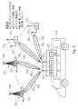
さらに他の実施形態によれば、UE200は、複数の独立した並列通信リンク208を介した信頼できる通信を必要とするデバイスに接続されてもよい。UE200は、自動車、バス、列車、またはドローンのような航空機のような機械または車両に結合または組み込まれてもよい。図2では、UE200はバス216の一部として示され、バス216の要素への接続のための、またはバスの乗客がUEに接続することを可能にするためのインターフェース218を含む。インターフェースは、例えばWiFiインターフェースなどの無線インターフェースへの接続を提供することができ、またはそれは、UE200がバス内の乗客のための集約ノードまたはホットスポットとして機能するように無線インターフェースであってもよい。例えば、バスの乗客は、バスの移動中に少なくとも1つのリンクが維持されることを保証する複数のリンク208を提供するUE200を使用して、1つまたは複数のモバイル通信ネットワークインフラストラクチャを介してインターネットに接続することができる。言い換えれば、UE200は、車両216内のユーザにモバイルホットスポットを提供し、ユーザは、高データレート無線インターフェース218を介してセルラーネットワークまたは複数のセルラーネットワークに高い信頼性で接続することができる。
According to yet other embodiments,
他の実施形態によれば、UE200を、例えば乗用車の一部として実装する場合、多くのユーザの多くの接続にバックホールを提供するのではなく、UEは、例えばライブビデオ伝送のために必要な帯域幅の集約に使用されてもよい。これは、可能な限り多くの物理リンク208を集約することにより、すなわち、アンテナアレイ200により可能な限り多くのネットワークエンティティ210に提供されるそれぞれの空間ビームによりリンク208を設定することにより達成される。これにより、複数の物理リンクが提供され、利用可能な帯域幅が集約され、例えば信頼性の高いライブビデオ伝送が保証される。
According to another embodiment, if the
他の実施形態によれば、UE200は、建物のような固定したエンティティに取り付けられた、またはその一部である固定ホットスポットであってもよい。
According to other embodiments, the
したがって、本発明の実施形態は、UE側で複数のアンテナまたは大規模MIMOアレイのような1つまたは複数のアンテナアレイを使用し、大規模MIMO基地局からのダウンリンクで見た場合にUEと同じようにBSなどの複数のエンティティ210を処理することによりマルチリンク接続を提供する。同じネットワーク内または異なるネットワーク内のいずれかにある並列の独立したリンク208の存在について実際のネットワークに通知する必要がほとんどまたはまったくないので、本発明の手法は、従来の手法を超える利点を提供し、その結果、本発明のユーザデバイスは、既存のネットワークインフラストラクチャにシームレスに導入することができる。さらに、アンテナによって空間ビームまたは指向性ビーム206を提供する本発明の手法は、UE200と各エンティティ2101~2104との間のリンク208を確実に分離し、それにより、例えば、信頼性、ダイバーシティ、データレート、多重化手順を改善する。また、より高速なハンドオーバー手順を実施することができる。
Thus, embodiments of the present invention use multiple antennas or one or more antenna arrays, such as a Massive MIMO array, at the UE side, with the UE and It provides multi-link connectivity by treating
図2の実施形態では、UE200はバス216の一部として実装されるものとして説明されたが、本発明の手法はそのような実施形態に限定されず、むしろ、本発明のユーザデバイスは、電子機器、ソフトウェア、センサ、アクチュエータなど、およびネットワーク接続のうちの1つまたは複数を含む任意のデバイスであってもよい。例えば、本発明のユーザデバイスは、固定デバイスまたは、例えば、スマートフォン、PDA、コンピュータなどのハンドヘルドデバイス、ロボット、車、電車などの地上車両、有人および無人の航空機(後者はドローンとも呼ばれる)などの航空機などの、モバイルデバイスの形で実装されてもよい。ユーザデバイスは、上記のネットワーク接続が埋め込まれた物理デバイス、建物、または任意のアイテムに含まれるか、またはそれに取り付けられてもよい。実施形態によれば、ネットワーク接続により、ユーザデバイスは、それぞれの無線通信リンクを介した無線ネットワーク要素への接続をスキャン/検索、検出、開始、確立、中止/終了、ハンドオーバー、維持、または監視することができ、例えば、データを交換し、および/または制御チャネルに追従またはそれを追跡することができる。例えば、場合によっては、ユーザデバイスがリンクを単に追跡して、必要に応じてアクティブ化できる利用可能なリンクの一種の「リスト」を取得できれば十分な場合がある。例えば、図2に示すリンクの1つが失敗し始めると、UEによってすでに監視されている別のリンクが、失敗したリンクによって提供される無線リンクを引き継ぐために選択される。このような場合、ユーザデバイスはリンクを介して常にアクティブに送信または通信するのではなく、リンクを受動的に追跡する。
Although the embodiment of FIG. 2 describes
上述のように、無線ネットワーク要素は基地局または他のユーザデバイスであってもよいが、さらなる実施形態によれば、それらは1つまたは複数のリンク転送要素、例えば1つまたは複数のさらなるユーザデバイス用の中継デバイスを含んでもよい。上記の中継デバイスは、例えば、衛星またはリピーター、または別のユーザデバイスとWiFiアクセスポイントの組み合わせであってもよい。 As mentioned above, the wireless network elements may be base stations or other user devices, but according to further embodiments they may be one or more link forwarding elements, such as one or more further user devices. may include a relay device for Such relay devices may be, for example, satellites or repeaters, or a combination of another user device and a WiFi access point.
図3は、本発明のユーザデバイス200を実装するための別の実施形態を示す。図3の実施形態では、概略的にのみ示されているユーザデバイス200は、乗用車216のような車両の一部であり、アンテナは、大規模MIMO、M-MIMO、アレイアンテナによって形成されている。4つの空間/指向性アンテナビーム2061、2062、2063および2064が、異なるモバイルネットワーク事業者MNO1~MNO3の一部であるそれぞれの基地局BSに対してそれぞれ独立した無線通信リンク2081~2084が確立されるアンテナアレイによって形成される。複数のリンク2081~2084は、いくつかの基地局BSおよび異なるモバイルネットワーク事業者にわたってUE側で同時に空間的に処理される。したがって、本発明の実施形態は、ML-UEとも呼ばれる新しいクラスのマルチリンクUE、およびマルチリンクが、UE側で異なる基地局または無線ネットワーク要素に形成された空間マルチリンクによって実現されるシステムを導入し、これは、同じまたは異なる周波数で、あるいは同じまたは異なる周波数帯域で動作する。
FIG. 3 shows another embodiment for implementing the
アンテナアレイ202は、アンテナアレイ200の異なるアンテナ素子202xを使用してそれぞれの空間的/指向性ビームを形成することによりUE200が同じまたは異なるモバイルネットワーク事業者の異なる基地局を認識し、互いに独立した異なる基地局への接続をセットアップするように、関連する空間ビーム2061~2064を形成する。実施形態によれば、アンテナは、6GHzを超える周波数で動作することができ、例えば、それは、ミリ波帯で、またはミリ波で動作することができる。アンテナアレイは、均一線形アレイ、ULAのような線形アンテナアレイ、均一平面アレイ、UPA、円筒状アレイなどのような平面アンテナアレイであってもよい。
本発明の手法によれば、異なる空間ビーム206によってUE200から複数の無線通信リンク208を提供することにより、リンクが一時的にブロックされているなどの理由でリンクの1つがフェードインまたは消失している場合でも、より堅牢であるように通信が改善される。これは、モバイルアプリケーションで頻繁に発生するシナリオである可能性がある。例えば、デバイス216が移動した場合でも、残りの非ブロックリンクを介した信頼できる通信が存在する。
In accordance with the techniques of the present invention, by providing multiple
図2および図3は、1つまたは複数の無線通信ネットワークを含むシステムの例を示し、そのそれぞれは、基地局または他のユーザデバイスのような1つまたは複数の無線ネットワーク要素を含み、本発明のユーザデバイスは、複数の無線ネットワーク要素との無線通信のために配置されている。図2および図3は、本発明の手法による単一のユーザデバイスのみが提供されるシステムを示しているが、本発明はそのような実施形態に限定されず、むしろそのようなシステムにおいて複数の本発明のユーザデバイス200が提供されてもよい。
Figures 2 and 3 illustrate examples of systems including one or more wireless communication networks, each of which includes one or more wireless network elements, such as base stations or other user devices, in which the present invention can be used. user devices are arranged for wireless communication with multiple wireless network elements. Although FIGS. 2 and 3 illustrate systems in which only a single user device is provided in accordance with the techniques of the present invention, the invention is not limited to such embodiments, but rather multiple user devices in such systems. A
図3は、本発明のユーザデバイスのみが、大規模MIMOアンテナアレイのような複数のアンテナまたはアンテナ素子202xを有するアンテナアレイ202を含み、無線通信ネットワークのそれぞれの基地局BSがセクターアンテナまたは無指向性アンテナを含むと想定される実施形態を示す。しかし、他の実施形態によれば、無線通信ネットワークのユーザデバイス200および基地局BSの両方は、基地局BSとユーザデバイス200との間にマルチポイントツーマルチポイント、MP2MP、接続性を作成するアンテナアレイを含んでもよい。当然のことながら、さらなる実施形態によれば、無線通信ネットワークの基地局のすべてではなく、それらのいくつかにアンテナアレイが設けられている。さらなる実施形態によれば、無線通信ネットワークの1つまたは複数の基地局BSがアンテナアレイを備えている場合、UEと無線ネットワーク要素の少なくとも1つとの間に複数の並列空間レイヤを確立するため、例えば、ユーザデバイス200と無線ネットワーク要素との間の無線通信リンクを介してデータレートを増加させるため、高次多重化方式は、UE200とアンテナアレイも有するそれぞれのBSとの間の通信のために使用されてもよい。例えば、図3のリンク2081を検討し、モバイルネットワーク事業者MNO3の関連する基地局BSにも大規模MIMOアレイのようなアンテナアレイが提供されていると仮定すると、実際のリンク2081は、複数の空間ビーム2061、2061’により形成されてもよく、それにより、UE200からMNO3の基地局BSへの複数の並列無線リンクを提供し、それによりデータレートが増加する。
FIG. 3 shows that the user device of the present invention only includes an
実施形態によれば、複数の独立した無線通信リンク2081~2084は、例えば、図3に示されているように、サービスまたはそれらの組み合わせによって、ネットワーク側で、ユーザ側で編成されてもよく、サービスは、ネットワークまたはユーザデバイスの内部または外部に配置できる。無線通信リンク上のトラフィックは、以下の図4と図5を参照して以下に説明するように、エンドツーエンドのE2Eトラフィック、例えば、外部サービスプロバイダからUE200またはUE200に結合されたデバイスへのトラフィックと呼ばれることもある。
According to embodiments, a plurality of independent wireless communication links 208 1 -208 4 may be organized at the network side, at the user side, for example by service or a combination thereof, as shown in FIG. Often services can be located inside or outside the network or user device. Traffic on the wireless communication link may be end-to-end E2E traffic, e.g., traffic from an external service provider to
言い換えると、実施形態によれば、オーケストレーションは、必ずしもネットワークまたはUE200に配置されているとは限らないサービスレベルであってもよく、むしろインターネットのサーバーのような実際のネットワークの背後にあるエンティティであってもよい。UE中心のマルチ接続オーケストレーションと呼ばれるトラフィックのオーケストレーションは、UEによって、サービス中心のマルチリンクオーケストレーションと呼ばれるローカルまたは分散方式でホストされたサービスによって、またはネットワーク中心のマルチ接続オーケストレーションと呼ばれる上記の基地局のような1つまたは複数のネットワーク要素によって行われてもよい。
In other words, according to embodiments, the orchestration may be a service level that is not necessarily located in the network or
実施形態によれば、UE200は、新規の接続識別を使用して、いくつかの無線ネットワーク要素に同時に接続することができ、例えば、仮想マルチUE IDは、ネットワークがマルチリンクアンカーUEを処理できず、レガシーネットワークのフォールバックと、様々なモバイルネットワーク事業者が運営するいくつかのネットワークへのマルチ接続を提供できない場合に使用できる。他の実施形態によれば、ML-UE200は、1つまたは複数のネットワークでそれ自体をリレーとして識別し、UE IDが不要であるか、リレーIDが使用されるかのいずれかである。例えば、リレーに結合されたUEなどのエンティティのIDは、リレーでカプセル化され、リレーを介したこれらのUEも、異なるまたは外部のモバイルネットワーク事業者のネットワークを使用できるようになる。
According to embodiments, the
上述のように、図2および図3の基地局またはUEのような無線ネットワーク要素は、1つまたは複数の無線通信ネットワークの一部であってもよい。例えば、1つまたは複数の無線通信ネットワークは、同じモバイルネットワーク事業者によって操作される1つまたは複数の無線ネットワーク、同じ事業者が運営するネットワークの要素である基地局BS1、BS2、BSnへの3つの独立した無線通信リンク用のアンテナ202を使用して3つの空間ビームを形成するUE200を示す図4に概略的に示す状況を含んでもよい。UEは、3つの空間ビームを形成して、例えば、単一の基地局への従来技術の手法では通常のように、ビデオストリーミングサービスなどの無線通信ネットワークに接続された外部ユニット220に接続するのではなく、高い接続信頼性を提供する。本発明の手法によれば、アンテナ202によって提供される3つの空間ビームは、基地局への独立した無線通信リンクを形成する、すなわち、十分な数のリンクが提供されるので、通信経路内の障害物222のために、基地局のうちの1つ、例えば、基地局BS3への接続が不可能である状況も、十分な数の接続またはリンクが確立され、高い信頼性と高いデータスループットが実現される。
As mentioned above, a wireless network element such as a base station or UE in FIGS. 2 and 3 may be part of one or more wireless communication networks. For example, the one or more wireless communication networks can be one or more wireless networks operated by the same mobile network operator, base stations BS 1 , BS 2 , BS n being elements of networks operated by the same operator. 4, which shows
他の実施形態によれば、UEは、図5に概略的に示すように、異なる事業者によって運営される無線通信ネットワークの一部である無線ネットワーク要素に接続することができる。再び、UE200は、3つの独立した無線通信リンクを確立するための3つの空間ビームを形成するアンテナ202とともに示す。図5のシナリオでは、3つの異なるモバイルネットワーク事業者1、2および3の基地局が利用可能であると想定され、UEは、第1の事業者の基地局BS12、第2の事業者の基地局BS21、および第3の事業者の基地局BS33への無線通信リンクを提供して、ネットワークへの、またネットワークを介した外部ユニット220への信頼できる接続を提供し、それにより、障害物2221、2222の問題、または基地局が所望の特性に従って動作しない、または過負荷になり、十分なスループットを提供しない問題を回避する。
According to another embodiment, the UE may be connected to radio network elements that are part of radio communication networks operated by different operators, as shown schematically in FIG. Again,
上記の実施形態は、セルラー無線通信ネットワークに関連して説明されてきたが、本発明の手法はそのようなネットワークに限定されない。本発明の手法は、衛星およびセルラーからローカルおよびパーソナルエリアネットワークまでの任意のタイプの無線通信ネットワーク、例えば無線パーソナルエリアネットワーク、WPAN、無線ローカルエリアネットワーク、WLAN、無線アドホックネットワーク(無線メッシュネットワークまたはモバイルアドホックネットワークとも呼ばれる)、MANET、無線メトロポリタンエリアネットワーク、無線ワイドエリアネットワーク、セルラーネットワーク、およびグローバルエリアネットワークにおいて実施されてもよい。さらに、本発明の手法は、上述のネットワークのいずれかを組み合わせた環境で実装されてもよい。言い換えれば、上記の無線通信ネットワークは、同じ無線アクセス技術、RAT、または異なるRATに基づいて動作する。無線技術の例は次のとおりである。 Although the above embodiments have been described in relation to a cellular wireless communications network, the techniques of the present invention are not limited to such networks. The techniques of the present invention can be applied to any type of wireless communication network from satellite and cellular to local and personal area networks, such as wireless personal area networks, WPANs, wireless local area networks, WLANs, wireless ad hoc networks (wireless mesh networks or mobile ad hoc networks), MANETs, wireless metropolitan area networks, wireless wide area networks, cellular networks, and global area networks. Additionally, the techniques of the present invention may be implemented in environments that combine any of the networks described above. In other words, the above wireless communication networks operate based on the same radio access technology, RAT or different RATs. Examples of wireless technologies are:
LTE、LTE-A、LTE-A Pro
5G/NR
LTE V2X
拡張されたV2X、5G/NRのeV2X、
IEEE 802.11、
IEEE 802.11p DSRC、
ブルートゥース(登録商標)、
IEEE 801.11ad、IEEE 802.11ay、IEEE 802.11acなどのWiFiバリアント
ETSI DECTおよびそのバリアント。
LTE, LTE-A, LTE-A Pro
5G/NR
LTE V2X
Enhanced V2X, 5G/NR eV2X,
IEEE 802.11,
IEEE 802.11p DSRC,
Bluetooth®,
WiFi variants such as IEEE 801.11ad, IEEE 802.11ay, IEEE 802.11ac ETSI DECT and its variants.
また、UE200が無線リンクを形成し得るネットワーク要素は、上述の無線通信ネットワークのいずれか1つから選択されてもよい。さらに、さらなる実施形態によれば、無線ネットワーク要素は、建物、機械、車両などのような他のエンティティの一部であり、これらはさらにネットワークに接続されてもよい。
Also, the network elements with which the
さらなる実施形態によれば、基地局および他のエンティティのような上記の無線ネットワーク要素は、それらが属するネットワーク内で、同じまたは異なるネットワークリソースを使用してもよい。例えば、図4を考慮するとき、UE200への接続に関与する基地局BS1~BSnの一部またはすべては、同じリソースで動作するか、または異なるリソースを使用してもよい。例えば、それぞれの無線通信リンクに関連付けられた/マッピングされたリソース要素を送信するための異なる周波数または異なる周波数帯域が使用されてもよい。これは、異なるネットワークで動作する無線ネットワーク要素にも適用される。
According to further embodiments, the above wireless network elements, such as base stations and other entities, may use the same or different network resources within the networks to which they belong. For example, when considering FIG. 4, some or all of the base stations BS 1 -BS n involved in connecting to the
図4および図5を参照して上述した実施形態では、モバイルネットワーク事業者の基地局が参照されているが、しかしながら、本発明の手法は、図4および図5の基地局の代わりに、またはそれに加えて、実施形態に従って、そのようなシナリオに限定されず、UE200の空間ビームによって提供される1つまたは複数の通信リンクは、異なる無線アクセス技術、例えば、60GHzのWiGigリンク(IEEE 802、11adまたはIEEE 802.11ay)、5.2GHzのWiFiリンク、3.5GHzの4Gまたは5Gリンクなどを実装するWiFiネットワーク、Bluetoothネットワーク、またはDECTネットワークまたはその他の帯域を使用するネットワークへのものであってもよい。
In the embodiments described above with reference to FIGS. 4 and 5, reference is made to a mobile network operator's base station; Additionally, according to an embodiment and not limited to such scenarios, the one or more communication links provided by the spatial beams of the
図4および図5の実施形態では、ユーザデバイス200は、ビデオストリーミングサービス220と通信するものとして説明されたが、任意の種類のサービスプロバイダ、例えばURLLCサービスが実装されてもよい。
In the embodiments of FIGS. 4 and 5,
図4および図5の外部ユニット220は、ユーザデバイス200が通信する宛先とも呼ばれてもよい。外部ユニット220は、遠隔機械操作または機械の閉ループ制御のためのサービスを実施してもよい。サービスプロバイダ220は、URLLCサービスを提供することができ、図5に示すように、さらなるリンク228を介してマシン230に接続される。インターフェース228は、外部ユニット220とエンティティ230との間の直接通信、無線通信、または有線通信であってもよく、または、例えば、イントラネットまたはインターネットなどの別のネットワークを介した接続であってもよい。
本発明の手法のさらに別の実施形態によれば、宛先220は、1つまたは複数のネットワーク要素、例えば、図2から図5を参照して上述した1つまたは複数の基地局であってもよい。そのようなシナリオでは、追加のエンティティ230は、図4および図5に示すモバイル通信ネットワークに接続されるか、または基地局の1つなどのネットワーク要素の1つに直接接続される。例えば、図4を検討する場合、外部ユニット220は、基地局BS1~BSnのうちの1つまたは複数に結合されてもよい。
In accordance with yet another embodiment of the present technique,
図5を参照して説明した例では、UEの通信の宛先を形成するエンティティは、外部ユニット220に結合されたマシン230として示されている。言い換えれば、宛先は次のネットワークノード、例えば基地局に向かっているか、別のUEや車のような他のノードへのマルチホップである可能性があり、それによってUEを一種のリレーまたは転送ノードにすることができる。
In the example described with reference to FIG. 5, the entity forming the UE's communication destination is shown as
他の実施形態によれば、目的地であるエンティティは、車両のようなモバイルデバイスであってもよい。UE200が提供される場所に応じて、例えば、それが別の機械または別の車両に提供される場合、M2M、V2VまたはV2X通信が実施されてもよい。
According to other embodiments, the destination entity may be a mobile device such as a vehicle. Depending on where the
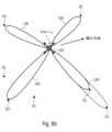
図6aは、本明細書に記載の教示に従って実装されるUE200が車両300に結合され、ユーザデバイス200のアンテナアレイ202によって形成されるそれぞれの空間ビームまたは指向性ビームを使用して複数の無線通信リンク2081~2085を提供する実施形態を示す。無線通信リンク2081~2084は、無線通信リンク208を確立するために、スモールセル基地局のような無線ネットワーク要素(図示せず)をそれぞれ含む複数の路側ユニット3021~3024へのV2X通信を提供する。路側エンティティ302は、道路304に沿ったランタン、交通標識、または建物であり得、それぞれのユニット302は、図4および図5を参照して上述したように、外部エンティティとの通信のために共通ネットワークまたは異なるネットワークに接続されてもよい。さらに、車両300は、本発明のUE200を介して、UE200のアンテナによって生成される空間ビームまたは指向性ビームの1つによっても形成される無線通信リンク2085を介して、さらなる車両306へのV2V通信を確立することができる。さらなる車両306は、路側エンティティと同様の方法で、無線通信のためのネットワーク要素210を含む。ネットワーク要素210は、ネットワーク接続性を提供する任意のデバイスとすることができ、実施形態によれば、無線ネットワーク要素210は、本発明の手法に従ってユーザデバイス200によって形成することもできる。点線3081、3082で示されるように、さらなる車両306も路側エンティティ3022および3024に接続されている。2つの車両300、306の間の信頼できる通信のために、本発明のユーザデバイス200は、直接リンク2085に加えて、さらなる独立した無線通信リンク2082、2084を介して、そして、車両300から車両306への通信を中継することができる2つの路側ユニット3022および3024からの無線リンク3081、3082を介して、マルチ接続を提供する。
FIG. 6a illustrates a
図6aを参照すると、他の実施形態によれば、地上車両ではなく、例えばドローンのような無人航空機などの航空機も使用できることに留意されたい。装置の飛行経路に沿って設けられた複数の固定要素へのマルチ接続のための本発明のユーザデバイス200を含むことができ、制御情報を受信し、位置情報を例えばシステムに送り返すためのネットワークへのドローンのより信頼できる接続をもたらす。
Referring to FIG. 6a, it should be noted that according to another embodiment, rather than ground vehicles, also aircraft, such as unmanned aerial vehicles, such as drones, can be used. Can include a
図6bは、本明細書に記載の教示に従って実施されるUEが空中輸送機、航空機、または無人機に接続される別の実施形態を示す。図6bには、それぞれのビーム206を介して地上の基地局BSに接続する本発明のユーザデバイス200を含むドローンが示されている。図6bに示す状況では、UE200からBS’へのUL接続は、BS’およびBS’’がビーム206’によってカバーされる同じセクターにあるため、BS’’との干渉を引き起こす可能性がある。UE200およびその関連UL RSについての知識を有する潜在的に干渉の影響を受けるすべてのBSは、UE200のために経験された感知された干渉を報告し、ネットワーク内のマルチリンクオーケストレータ(以下を参照)はそれに応じてリンク206を管理して干渉レベルを低減することができる。例えば、ビーム206’の代わりに、BS’’’に向けられた別のビーム206’’がULに使用されてもよい。
FIG. 6b illustrates another embodiment in which a UE is connected to an air vehicle, aircraft, or drone, implemented according to the teachings described herein. Fig. 6b shows a drone comprising
ダウンリンク選択についても同じことが当てはまる。というのは、UE200は、BS’から、BS’’に干渉されたUE200へのDL接続中にBS’’からの干渉レベルを認識し、それに応じてアクティブビームを206’’に切り替えるからである。
The same applies for downlink selection. This is because the
さらなる実施形態によれば、空中デバイスは、近接BSの公表された近隣リストにあるものを超えてBSにマルチリンクアンカーするためにBSの拡張カバレッジを活用することができる。 According to further embodiments, an airborne device can leverage the extended coverage of a BS to multi-link anchor to BSs beyond those on the advertised neighbor list of neighboring BSs.
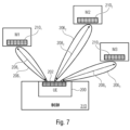
図7は、本発明のユーザデバイス200が、例えば複数の機械M1、M2、およびM3を含む工場内で機械制御310に結合されるか、その一部である別の実施形態を示す。本発明のユーザデバイス200は、そのアンテナ202により、それぞれの無線ネットワーク要素2101~2103に結合または組み込まれたそれぞれのマシンM1~M3への3つの無線通信リンク2081~2083を確立することにより、マルチ接続性を提供する。それぞれの無線リンク208は、ユーザデバイス200のアンテナまたはアンテナアレイ202によって生成された独立した空間/指向性ビーム2061、2062および2063を使用して形成される。機械制御310は、機械の動作を監視し、独立したリンクを介して機械の動作を制御するために、それぞれの機械に信号を送信/受信することができる。機械は、ロボットなどを含むあらゆる種類の機械であってもよい。
FIG. 7 shows another embodiment in which the
図8aは、一実施形態による本発明のユーザデバイスのブロック図を示す。UE200は、複数のアンテナまたはアンテナ素子202xを有するアンテナアレイ202を含む。他の実施形態によれば、複数のそのようなアンテナアレイ202をUE200に設けることができる。アンテナアレイ202は、プリコーダ320に結合されている。プリコーダ320は、コードブックを含むか、コードブックに結合されて、個別の独立した無線通信リンクそれぞれに対して少なくとも2つの空間的に分離された電磁送信/受信ビームを形成する。さらに、UE200は、プリコーダに結合され、また信号を入力/出力するためにインターフェース218にも結合されたそれぞれの信号処理チェーン2041~204nを定義する1つまたは複数の信号プロセッサを含む。実施形態によれば、アンテナアレイ202は、多数のアンテナ素子を有する大規模MIMOアンテナアレイであってもよい。上述のように、複数の信号処理チェーン2044~204n、例えば、無線通信リンクのそれぞれに対する信号処理チェーンを実装するために、単一の信号プロセッサまたは複数の信号プロセッサが提供されてもよい。信号処理チェーンは、リンクごと、基地局ごと、モバイルネットワーク事業者ごとに、以下のうちの1つまたは複数をサポートする。
Figure 8a shows a block diagram of the user device of the present invention according to one embodiment.
DL時間と周波数の同期、近隣リストの処理、
DL/ULやH-ARQなどのリソース割り当ての処理、
ULタイミングアドバンスTA、
電力制御、
引き継ぎ手順のトリガと処理。
DL time and frequency synchronization, neighbor list processing,
processing of resource allocation such as DL/UL and H-ARQ;
UL Timing Advance TA,
power control,
Triggering and processing handover procedures.
以下では、複数の無線通信リンクを介した通信を扱う本発明の手法の実施形態を説明する。 In the following, embodiments of the present technique dealing with communication over multiple wireless communication links are described.
物理層の再送信メカニズム
実施形態によれば、図2~図7のいずれか1つに示すシステムは、再送信に適したリンクの指示を含む、H-ARQのような物理層再送信メカニズムを実装してもよい。例えば、スペクトル効率を改善するために、H-ARQなどの物理層再送信メカニズムをマルチリンクUE200および基地局BSなどの各無線ネットワーク要素に適用することができる。基地局などの宛先がメッセージを復号化できない場合、マルチリンクUE200からの再送信を要求するために、非確認応答、NACKメッセージを送信することができる。宛先は、複数のリンクのどれが再送信の優先リンクであるかを示すことができる。リンクの品質/信頼性に関する情報は、異なる独立した無線リンクを介してUEに接続された各基地局が互いに認識している場合、例えばX2インターフェースまたは他のバックホール接続を介して基地局で共有することができる。リンク品質/信頼性は、各リンクに関する符号化情報の尤度比を分析することによって見つけることができ、所定のしきい値を超える品質/信頼性を有するリンクが再送信のために選択されてもよい。
Physical Layer Retransmission Mechanisms According to embodiments, the system shown in any one of FIGS. May be implemented. For example, a physical layer retransmission mechanism such as H-ARQ can be applied to each wireless network element such as
ハンドオーバー
実施形態によれば、図2~図7のいずれか1つに示すシステムは、各無線伝送リンク208に対して、ネットワーク内の別のアンカーポイントまたは基地局のような別の無線ネットワーク要素への独立したハンドオーバー手順をトリガし、要求し、実行してもよい。例えば、ハンドオーバーの高度なトリガおよび遅延トリガは、ネットワークを介して「クローリング」を実装し、同時に特定のターゲットデータレート、レイテンシ、冗長性などを満たすために必要な数のリンク208を接続モードでできるだけ多く維持することができる。
Handover According to an embodiment, the system shown in any one of FIGS. 2-7 is configured such that for each
他の実施形態によれば、ネットワークまたはインターネットからロードすることができる拡張近隣リストのような近隣リストを使用して、ML-UE200が、2つ以上の階層の無線ネットワーク要素、異なるモバイルネットワーク事業者、異なる無線アクセス技術などにわたる同時リンクに対して従来の近隣リストで指定された範囲を超えて接続できるようにすることができる。
According to other embodiments, the ML-
さらに別の実施形態によれば、システムは、使用デバイスの所定の経路に関する知識および/または利用可能になる無線ネットワーク要素への無線通信リンクに関する知識に基づいて、予想されるハンドオーバーおよび/または新しいリンク確立を実行することができる。 According to yet another embodiment, the system determines the expected handover and/or new route based on knowledge of the predetermined path of the device in use and/or knowledge of wireless communication links to wireless network elements that become available. Link establishment can be performed.
さらなる実施形態によれば、ハンドオーバーは、アナウンスされた近隣リストからの1つのBSから隣接BSへの従来のハンドオーバー、またはRACHのような従来のリンク接続/確立手順を使用し、新しいリンクを介したエンドツーエンド接続を提供する、近隣リストでアナウンスされていない別の無線ネットワーク要素への新しいリンクの確立に基づくハンドオーバーであってもよい。 According to a further embodiment, the handover uses a conventional handover from one BS to a neighboring BS from an announced neighbor list or a conventional link connection/establishment procedure such as RACH to establish a new link. The handover may be based on the establishment of a new link to another wireless network element not announced in the neighbor list that provides end-to-end connectivity via.
ダウンリンクDLシグナリングの活用
実施形態によれば、本発明のUE200は、異なる基地局のような異なる無線ネットワーク要素からのダウンリンクDLシグナリングを活用して、2つ以上の無線ネットワーク要素を区別し、独立に要素と同期して、DL制御チャネルの並列復号化/処理/取り扱いを提供することができる。言い換えると、DLシグナリングは異なる基地局/アクセスポイントから送信され、UEは2つ以上の基地局信号を区別して、ダウンリンク制御チャネルの並列復号化/処理の通信を同期させることができる。したがって、本明細書に記載の教示に従って実装されるUE200は、例えば、いくつかの無線フレームにわたってなど、長期間にわたって、複数のリンクを同じアクティブまたはアクティブ化の準備ができた状態に保つ。
Utilizing Downlink DL Signaling According to embodiments, the
増加したダイバーシティ
実施形態によれば、本発明の手法は、コードダイバーシティ、空間ダイバーシティ、時間ダイバーシティまたは周波数ダイバーシティの増加のように、ダイバーシティを増加させる。ダイバーシティを高めるために、UE200は、複数の無線通信リンクを介して、例えば同時に第1の無線通信リンクおよび第2の無線通信リンクを介してメッセージを送信および/または受信することができる。さらに他の実施形態によれば、メッセージは分割されてもよく、メッセージの一部は、第1および第2の無線通信リンクを介して同時に多重送信されてもよい。
Increased Diversity According to embodiments, the techniques of the present invention increase diversity, such as code diversity, spatial diversity, time diversity or frequency diversity. To enhance diversity, the
複数の無線通信リンクを介してメッセージまたはメッセージの一部を同時に送受信する場合、無線通信リンクの1つを介した通信が正常に復号化または受信されない場合がある。そのような状況では、メッセージまたはメッセージの一部の再送信が必要であり、UEは1つまたは複数の異なる無線通信リンクを介して、H-ARQ再送信メッセージなどの再送信メッセージを送信または要求することができる。実施形態によれば、再送信メッセージは、メッセージ内またはメッセージの一部内のデータの冗長性を含むことができ、冗長性は、チェイス結合または増分冗長性を含むことができる。さらに他の実施形態によれば、再送信の要求に応じて、メッセージ全体またはメッセージの一部の完全な再送信を開始することができる。 When sending and receiving messages or portions of messages simultaneously over multiple wireless communication links, the communication over one of the wireless communication links may not be successfully decoded or received. In such situations, retransmission of messages or parts of messages is required and the UE transmits or requests retransmission messages, such as H-ARQ retransmission messages, over one or more different wireless communication links. can do. According to embodiments, the retransmitted message may include redundancy of data within the message or within portions of the message, and the redundancy may include chase combining or incremental redundancy. According to yet another embodiment, a complete retransmission of the entire message or part of the message can be initiated in response to a retransmission request.
基地局のようなそれぞれのネットワーク要素が、UEからネットワークへの既存の独立した並列無線通信リンクを認識していない場合、再送信は、異なるリンクを介してそれぞれのネットワーク要素を介してUEへのデータのフローを制御することもできるトップエンティティによって制御されてもよく、すなわち、再送信は、例えば、図4および図5を参照して上で説明されたように、サービスプロバイダによって、実際のネットワーク要素の外側の上部で処理されてもよい。基地局またはそれに結合するエンティティなどの無線ネットワーク要素が異なる無線通信リンクを認識している場合、再送信メッセージは、各基地局の制御下で異なる無線通信リンクを介して協調的に送信されてもよい。このような状況では、再送信により、2つ以上のリンクが多重化リンクまたは冗長リンクとして利用されてもよい。 If each network element, such as a base station, is unaware of the existing independent parallel wireless communication links from the UE to the network, retransmissions may be performed via different links to the UE via each network element. It may also be controlled by a top entity that can also control the flow of data, i.e. retransmissions are controlled by the service provider, for example as explained above with reference to FIGS. It may be treated on the outside top of the element. If wireless network elements, such as base stations or entities coupled thereto, are aware of different wireless communication links, retransmission messages may be transmitted cooperatively over different wireless communication links under the control of each base station. good. In such situations, retransmission may utilize two or more links as multiplexed or redundant links.
したがって、上記の実施形態によれば、元のメッセージは多重モードで送信されてもよいが、H-ARQに使用されるような繰り返しは、選択された別のパス、または使用可能なパス、空間/方向ストリーム、および/または周波数で異なるダイバーシティを使用してもよい。 Thus, according to the above embodiments, the original message may be sent in multiplexed mode, but the repetition, as used for H-ARQ, may be performed on another selected path, or an available path, space Different diversity in /directional streams and/or frequencies may be used.
増加したコードダイバーシティ
実施形態によれば、UE200がN個の異なる無線通信リンクに対してN(N>1)の空間ビームまたは指向性ビームを形成するという本発明の思想により、増加したコードダイバーシティが提供される。送信されるメッセージまたは送信されるメッセージの一部を符号化でき、コードワードのN個のコピーが生成され、N個の異なる無線通信リンクを介して送信される。別の実施形態によれば、メッセージまたはメッセージの一部を符号化し、得られたコードワードをN個のサブコードワードに分割し、N個の異なる無線通信リンクを介して送信することができる。
Increased Code Diversity According to embodiments, the idea of the present invention that the
そのようなシナリオでは、基地局のようなそれぞれの無線ネットワーク要素は、メッセージの部分を収集し、バックホールインターフェースを介したデータの交換を含んでもよいメッセージの部分の共同処理を実行することができる。これは、各無線ネットワーク要素が、UEから異なる基地局に提供される複数の独立した無線通信リンクを認識している状況で可能である。それぞれのネットワーク要素が独立したリンクを認識していない場合、他の実施形態によれば、無線ネットワーク要素がメッセージの一部をそれに接続されている1つまたは複数のエンティティに転送し、次に、エンティティがメッセージの部分を収集し、メッセージの部分の共同または分散処理を実行する。言い換えると、コードワードの部分または断片の最終的な組み合わせは、ネットワークエンティティのどこかで、またはサービスがアンカー/ホストされるサービスレベルで行われる。 In such scenarios, each wireless network element, such as a base station, can collect parts of the message and perform joint processing of the parts of the message, which may include exchanging data over the backhaul interface. . This is possible in situations where each radio network element is aware of multiple independent radio communication links provided from the UE to different base stations. If each network element is not aware of independent links, according to another embodiment, the radio network element forwards part of the message to one or more entities connected to it, and then: Entities collect message parts and perform collaborative or distributed processing of message parts. In other words, the final combination of codeword parts or fragments takes place somewhere in the network entity or at the service level where the service is anchored/hosted.
実施形態によれば、複数のリンクのメッセージのそれぞれの部分の配信は、すべての部分が受信された場合でも、実際のコンテンツを取得できない場合があり、ネットワークコーディングなどの追加の処理が必要になる。メッセージ/データフローの各部分は、第1のステップ/段階で、分散方式で処理/復号化され、その後に、第2の段階/ステップで、第1の段階の部分を組み合わせた共同処理によってさらなる処理が実行される。例えば、それぞれの基地局またはネットワーク要素で、特定のビットが特定の値を有する確率を示すソフトビットが生成され、これらのソフトビットは、受信されたソフトビットに基づいてハードビットを生成する共有エンティティに配信され、ビットの最終値を定義する。例えば、メッセージの同じ部分で異なるリンクを介して、または異なるネットワーク要素から異なるソフトビットを受信する場合、ハードビットを生成する共有エンティティは、特定の値に対して最も高い確率を有するソフトビットを選択することができる。 According to embodiments, delivery of each part of a message for multiple links may not retrieve the actual content even if all parts are received, requiring additional processing such as network coding. . Each part of the message/data flow is processed/decoded in a distributed manner in a first step/stage and then further processed/decoded in a second stage/step by jointly processing parts of the first stage. Processing is performed. For example, at each base station or network element, soft bits are generated that indicate the probability that a particular bit has a particular value, and these soft bits are generated by a shared entity that generates hard bits based on the received soft bits. defines the final value of the bit. For example, when receiving different soft bits over different links or from different network elements in the same part of the message, the sharing entity that generates the hard bits selects the soft bit with the highest probability for a particular value. can do.
さらなる実施形態によれば、ユーザデバイスはメッセージを暗号化することができる。 According to further embodiments, the user device can encrypt the message.
増加した空間/時間ダイバーシティ
実施形態によれば、データパケットまたはメッセージの複数のコピーを複数のリンクを介して送信することにより、空間および時間のダイバーシティを増加させることができる。UE200は、送信されるメッセージまたはメッセージの一部をコピーし、その後に、メッセージと、第1および第2の無線通信リンクのコピーおよびメッセージの他の部分とを送信することができる。例えば、マルチリンクUE200は、同じメッセージまたはデータパケットのN個のコピーを生成し、同じ方式/パターンまたは異なる方式/パターンのいずれかであるチャネルコーディング方式およびインターリーバパターンをメッセージまたはデータパケットの各コピーに適用することができる。チャネル符号化後に得られたN個のコードワードは、N個の異なる無線通信リンク208を介して宛先に並行して送信され、宛先は1つまたは複数の基地局であってもよい。宛先では、基地局が例えばX2インターフェースを介して複数の独立したリンクに関する知識を有していれば、受信した情報が基地局によって交換され、共同で処理される。ジョイントチャネルデコーダは、復号化処理中にメッセージの複数のコピーの相関を活用することができる。複数のリンクからのデータの十分な情報を蓄積することにより、宛先はメッセージを復号化することができる。メッセージを復号化できない場合、宛先はマルチリンクUEにNACKを送信して、メッセージの再送信を要求することができる。宛先は、マルチリンクUEへの再送信の優先リンクを示すこともできる。各再送信で、マルチリンクUEは、オプションで、それぞれ異なるチャネル符号化方式とインターリーバパターンによってメッセージを符号化およびインターリーブすることができる。
Increased Space/Time Diversity According to embodiments, space and time diversity can be increased by transmitting multiple copies of a data packet or message over multiple links. The
実施例によれば、チャネル符号化方式を単純に保つために、単純な発生器を備えたドープされたアキュムレータコードが使用され、そのようなコードは冗長性を導入せず、対応するチャネルデコーダは中程度の複雑さのみを必要とする。さらなる実施形態によれば、ファウンテンコードを使用して、メッセージを正常に復号化するために、受信機またはデコーダのような十分な数の部分が宛先に到着するまで、メッセージ全体の多くの部分を送信する送信方式に導くことができる。そのようなシナリオでは、H-ARQと同様のフィードバックにより、パケットのさらなる送信を終了させることができる。 According to an embodiment, a doped accumulator code with a simple generator is used to keep the channel coding scheme simple, such a code introduces no redundancy and the corresponding channel decoder is Requires only moderate complexity. According to a further embodiment, the fountain code is used to decode many parts of the entire message until enough parts arrive at the destination, such as a receiver or decoder, to successfully decode the message. It can lead to the transmission method to send. In such a scenario, H-ARQ-like feedback can terminate further transmission of the packet.
UL/DLスケジューリング
実施形態によれば、本発明のUE200は、アップリンクULおよび/またはダウンリンクDLを制御または調整することができ、ならびに/あるいはアップリンク通信および/またはダウンリンク通信におけるリンク適応を制御または調整することができる。実施形態によれば、UE200は、1つまたは複数の無線ネットワーク要素のリンク制御、例えば上記の図に示すような基地局のリンク制御にアクセスして、それぞれの無線通信リンクを介したアップリンク/ダウンリンクのリソースのスケジューリングを直接制御することができる。他の例によれば、リンク制御への直接アクセスは利用できない場合があるが、特定の状況が回避されるように、各基地局のリンク制御に関する情報の送信を制御すること、例えば、同時に2つの無線通信リンクの同時ハンドオーバーにより、スケジューリングの間接制御を実施することができる。
UL/DL Scheduling According to embodiments, the
さらなる実施形態によれば、UEは、アップリンク/ダウンリンクにおけるリソースおよびリンク適応を制御/調整して、UE自体が選択することができる物理リソースブロックなどのリソースの専用セットを提供することができ、そのようなPRBに対して、UEは、それぞれの無線通信リンクで変調、コーディング、およびコードワード配布を選択することができる。この手法は、UEが受信機であり、干渉レベルを含むチャネル状態を観察し、通常、リソースの特定のロード/使用を要求するために、PMI、CQIなどのいくつかのインジケータを基地局にレポートするダウンリンクで有益である。そのような値が送信の成功につながった場合、基地局が決定し、UEは別のラウンドのフィードバックを報告する。 According to further embodiments, the UE can control/coordinate resources and link adaptation in the uplink/downlink to provide a dedicated set of resources, such as physical resource blocks, from which the UE itself can choose. , for such PRBs, the UE can select modulation, coding, and codeword distribution on each wireless communication link. This approach assumes that the UE is the receiver and observes channel conditions, including interference levels, and typically reports some indicators such as PMI, CQI, etc. to the base station to request a specific load/use of resources. useful in downlinks to If such values lead to successful transmission, the base station decides and the UE reports another round of feedback.
アップリンク/ダウンリンクスケジューリングに関するさらなる実施形態によれば、本発明の手法によるML-UE200は、大規模MIMOアレイなどのアンテナアレイを使用して、空間多重化による共通リソースでできる限り多くの、ストリームとも呼ばれる、指向性/空間ビームを送受信することができる。共通リソースには、共通の時間/周波数リソースが含まれてもよい。LTE標準のような従来の手法は、基地局でのみアップリンク/ダウンリンクスケジューリングを実行するが、本発明の手法に従って、異なる基地局間で十分なバックホールがないかまたはバックホールがない状況を処理することができ、異なるモバイルネットワーク事業者の基地局に接続する場合がそうである。そのような場合、基地局は、許容可能なML-UE中心のスケジューリング決定と、対応するレート割り当てまたはリンク適応を提供する方法を知らない。これは、基地局で利用可能なグローバルCSIがなく、各基地局にはローカルCSIのみがあるためである。アップリンクの場合、各BSが、特定のML-UEの同時スケジュールされた他の基地局とそれ自体のアップリンクストリームがどれだけ干渉するかを知らないという意味で、スケジューリングには困難または不確実性がある。そのようなシナリオでは、実施形態によれば、アップリンクスケジューリングをUE側で実行することができるが、そうでない場合、そのようなアップリンク干渉はML-UEのアップリンクスループットを著しく低下させる可能性が最も高いからである。
According to a further embodiment for uplink/downlink scheduling, the ML-
例えば、UEは、複数の潜在的な基地局に同じアップリンク/ダウンリンクリソースブロック(共通のアップリンク/ダウンリンクリソースブロックとも呼ばれる)を要求することができ、UEがいくつかの基地局から許可を取得すると、UEは、許可した基地局からのCSIフィードバックをトリガすることができる。報告されたCSI(RI/PMI/CQI)を考慮して、UEはプリコーダによって提供されるビーム形成行列の最適なセットをスケジュールする。次に、UEは、UL/DL制御情報を基地局にシグナリングすることにより、リンク適応を実行することもできる。言い換えれば、そのような実施形態によれば、本発明のML-UE200は、従来の大規模MIMOシステムにおける基地局と同じ役割を果たすことができる。
For example, a UE can request the same uplink/downlink resource block (also called a common uplink/downlink resource block) from multiple potential base stations, and the UE can receive grants from several base stations. , the UE can trigger CSI feedback from the allowing base stations. Considering the reported CSI (RI/PMI/CQI), the UE schedules the optimal set of beamforming matrices provided by the precoder. The UE can then also perform link adaptation by signaling UL/DL control information to the base station. In other words, according to such embodiments, the ML-
独立した電力制御
さらなる実施形態によれば、ユーザデバイス200は、例えば、CSI、CQI、PMIおよびH-ARQハンドオーバーなどを含む独立したリンクフィードバックのために、無線通信リンクの独立した管理を提供してもよい。
Independent Power Control According to further embodiments,
集約ノード
本発明の実施形態によれば、やはり上記で簡単に述べたように、UE200は、集約ノードに接続された複数のさらなるデバイスのための集約ノードとして動作してもよい。
Aggregation Node According to embodiments of the present invention, as also briefly mentioned above, the
例えば、本発明のUE200は、バス、電車または飛行機のような移動ホットスポットの集約ノードであってもよく、車両に位置するいくつかのデバイスは集約ノードに接続されてもよい。接続されたデバイスは、独自のID、特定のプロパティなどを空間リンクIDに転送することができ、その逆も可能である。マルチリンク接続は、異なるMNOのネットワークに接続でき、反対側のデバイスはMNOごとにグループ化することができる。デバイスは、例えばサービスのマルチMNOアンカーリングによって、ネットワークのいずれか1つにアンカーされた「トランスコードされた」リンクを取得することができる。
For example, the
アナログビームフォーミング構成要素の多重化
さらなる実施形態によれば、ユーザデバイスは、例えば、それぞれのシグナリングチェーン204について図8aに示す信号プロセッサに実装される変調器/復調器を含んでもよい。アンテナアレイは、大規模MIMOアンテナアレイ202を含んでもよく、アンテナアレイ202内のアンテナ素子202xのすべてまたはグループは、変調器/復調器との間で同じRF信号を送受信してもよい。RF信号に言及する場合、変調器から来るアナログ信号を意味する。これは、DAC後のアナログドメインのベースバンド信号であってもよいし、中間周波数まで混合されてもよい。ビームフォーミングは、アナログビームフォーミングを生成するために、例えば位相シフタまたは並列ステージでの固定位相遅延との混合によって実行されるため、すべてのアンテナ要素が独自のトランシーバチェーンを有するわけではない。言い換えれば、それぞれアナログビームフォーミングまたはハイブリッドビームフォーミングの場合、アンテナアレイ202またはアンテナグループ202x内のすべてのアンテナは、変調器から同じRF信号を受信してもよい。この信号は、アンテナごとに個別にパラメータ化可能な位相で位相シフトされてもよく、位相でパラメータ化されたすべてのアンテナを使用すると、ターゲット受信機に向けて最大SINRが得られ、同時に他のすべての受信機での干渉が最小限に抑えられる。しかし、現在のデータレートと干渉除去の要件がそれほど高くない場合は、ターゲット受信機へのシグナリングに必要なアンテナまたはグループの数が少なくても十分である。送信機はML-UE200であり、受信機は基地局または他のUEのような他のネットワーク要素であってもよく、単一のML-UEから複数の基地局への複数のリンクを並列に確立すると必要なビームフォーミングハードウェアに関する統計的多重化ゲインが得られる。例えば、3つの基地局への3つの平行ビームをサポートする場合、アンテナまたはグループの数は、単一リンクのハードウェアの3倍よりも大幅に少なくてもよい。
Multiplexing of Analog Beamforming Components According to further embodiments, user devices may include modulators/demodulators implemented, for example, in the signal processor shown in FIG. 8a for each signaling
したがって、さらなる実施形態によれば、図8aのコントローラ322のようなコントローラは、例えば各無線通信リンクの現在のデータレート要件に従って、無線通信リンクごとのアンテナの数を動的に増減する、ならびに/あるいは無線通信リンクの数、および/または無線通信リンクを生成するために使用されるアンテナアレイのアンテナ要素、および/または無線通信リンクごとの空間ビームの数を増減するように設けられてもよい。
Thus, according to further embodiments, a controller, such as
図8bは、本発明のユーザデバイスの1つまたは複数のアンテナアレイを実装するための実施形態を示している。1つまたは複数のアンテナアレイは、ミリ波帯域で動作する複数のアンテナ素子202x、例えば8×8から数百までを含んでもよい。第1の実施形態によれば、アレイ200は、すべてのアンテナ素子202xを使用して複数のビーム206を形成するように制御されてもよい。第2の実施形態によれば、複数のサブアレイ2021、2022がそれぞれのビーム206を形成するために使用されるように、アレイを制御することができる。
Figure 8b shows an embodiment for implementing one or more antenna arrays of a user device of the invention. The one or more antenna arrays may include
リンク状態に関するプロトコル
さらなる実施形態によれば、本発明の手法は、例えば、基地局のようなそれぞれのネットワーク要素によって適切な測定を実行することにより、または、無線通信リンクに関連するKPIのようなそれぞれのパラメータを取得するためにUE200で実行される測定により、または、通信の動作、例えば通信動作に関するいくつかの情報を提供する要求された再送信の数、すなわち特定のデータを送信するために通信リンクがどの程度優れているかを監視することにより、ネットワークレベルのいずれかで、1つまたは複数の無線通信リンクの状態に関する情報を取得することを含むことができる。1つまたは複数のチャネルの状態に関する情報は、例えば、測定が完了すると、特定の要求が発行されると、または特定の時間もしくは間隔で、システム全体の各エンティティ間で送信または配信されてもよい。例えば、実施形態によれば、得られた情報を使用して、例えば、ユーザデバイスまたは他のエンティティから受信した情報に応じて、異なる無線通信リンク上の通信を動的に適応させることができる。
Link State Protocols According to a further embodiment, the inventive approach may be implemented by performing appropriate measurements by respective network elements, such as base stations, or KPIs related to wireless communication links. by measurements performed in the
E2Eマルチリンクオーケストレーション
さらなる実施形態によれば、本発明の手法は、E2Eマルチリンクオーケストレーションを提供することができる。
E2E Multilink Orchestration According to a further embodiment, the techniques of the present invention can provide E2E multilink orchestration.
実施形態によれば、E2Eマルチリンクオーケストレーションは、ネットワークへのアクセスおよびサービスに必要とされる可能性があるリンクIDおよびユーザIDのオーケストレーションを含む。 According to embodiments, E2E multi-link orchestration includes orchestration of link IDs and user IDs that may be required for network access and services.
図9は、本発明の実施形態によるオーケストレータを含むネットワークの概略図である。本発明のUE200は、それぞれの基地局BS1~BS3を介して、例えばインターネットまたは図示した環境の他の場所に位置するサービスへの3つの独立したリンク2081~2083を提供する。図9では、UEとサービスとの間の論理接続が矢印E2Eで表されている。基地局は、それぞれのバックホール接続BH1~BH3によってサービスに接続される。オーケストレータ400は、マルチリンクオーケストレータまたはマルチIDオーケストレータまたはその両方であってもよい。マルチリンクオーケストレータとマルチIDオーケストレータは、同じエンティティまたは個別のエンティティで、集中化または分散された方法で実装することができる。オーケストレータは、インターネットのサーバーのような実際のネットワークの背後にあるエンティティであってもよいし、UEにあってUE中心のマルチ接続またはマルチリンクオーケストレーションを提供してもよいし、あるいは、ネットワーク中心のマルチ接続オーケストレーションを提供するために、上記の基地局のような1つまたは複数のネットワーク要素にあってもよい。
FIG. 9 is a schematic diagram of a network including an orchestrator according to an embodiment of the invention. The
マルチリンクオーケストレータは、リンク208およびバックホール接続BHを介したE2E接続のための送信またはデータフローを制御する。マルチリンクオーケストレータは、符号410で概略的に表されるように、信頼性、レイテンシデータレートなどのE2E通信の特定の基準に従ってE2E接続に結合されたリンクを利用するために、例えば、データレート、干渉レベル、輻輳、負荷などのKPI(主要業績評価指標)によって記述される、リンク208およびバックホール接続BHの条件についての知識を活用することができる。このような知識は、ネットワーク要素、ネットワーク内の任意のエンティティ、またはUE200など、サービスまたはネットワークによって提供されてもよい。マルチリンクオーケストレータは、EPC、進化したパケットコア、4Gネットワークの機能など、コアネットワークのエンティティとも対話することができる。
The Multilink Orchestrator controls the transmission or data flow for the E2E connection over the
マルチリンクオーケストレータは、例えば、制御シグナリングを介して、ネットワーク要素またはリンクに関連するエンティティ、例えばスケジューラ、リンクコントローラ、ハンドオーバーコントローラなどで直接に、あるいは、サービスまたはリンク固有のパラメータ、例えば保証ビットレートサービス、ULLRCなどに基づいて間接的に、リンクの性能関連パラメータを制御することができる。 The Multilink Orchestrator may, for example, directly in a network element or entity associated with the link, e.g. scheduler, link controller, handover controller, etc., via control signaling, or through service or link specific parameters, e.g. guaranteed bitrate. Indirectly based on service, ULLRC, etc., the performance related parameters of the link can be controlled.
実施形態によれば、UE中心のマルチリンクオーケストレータは、特にグラントフリーアクセス手順を使用するULについて、基地局スケジューラを調整/調整することにより、データルート/フロー選択または優先順位付けにより、URLLCなどの重要なサービスに必要なリンクを制御することができる。さらに、UEおよび/またはサービスは、オンデマンドで、または応答時間、再送信試行などの所定の間隔で、エンドツーエンドリンク性能テストをトリガすることができる。 According to embodiments, the UE-centric multi-link orchestrator, especially for the UL with grant-free access procedures, by coordinating/coordinating the base station scheduler, by data route/flow selection or prioritization, by URL LLC, etc. You can control the links required for your critical services. Additionally, the UE and/or service can trigger end-to-end link performance tests on demand or at predetermined intervals such as response time, retransmission attempts, and the like.
例えば、レイテンシクリティカルなデータは、最速のリンク、例えば、必要なリソースブロックRBが利用可能なリンクおよび/またはH-ARQ再送信の最小数が予想されるリンクを介して、UE200によって常にルーティングされてもよく、および/または最低のエンドツーエンド遅延が予想される。さらに、レイテンシが重要なデータが分割され、リンクを介して送信されてもよい。スケジューリング選好決定のスケジューリングは、UEで行われてもよく、基地局などの関連するネットワーク要素に適切に通信されてもよい。
For example, latency-critical data is always routed by the
マルチIDオーケストレータは、1つまたは複数の無線ネットワークへのアクセスに使用される無線通信リンク208の加入者識別などの異なるIDを制御する。IDは、ユーザデバイスを認証し、ネットワークおよび/またはネットワークスライス、サービス、KPIレポート要求などの特定のネットワーク機能へのアクセスを許可するために使用されてもよい。異なるIDは、共通のマルチリンクUE IDに結合されてもよい。そのようなマルチリンクUE IDは、1つまたは複数のネットワークでより効率的に処理されてもよい。
A multi-ID orchestrator controls different IDs, such as subscriber identities for
利点
上記で詳細に説明した本発明の手法は、従来技術の手法よりも多くの利点を提供する。本明細書で説明する教示によれば、基地局などのいくつかのネットワーク要素へのリンクの集約が同時に可能になり、データレートがいくつかの基地局への空間多重化または周波数多重化によって増加するため、リンクダイバーシティが提供され、リンクの安定性が向上し、停止が減少するだけでなく、複数の基地局間のバックホール接続の負荷バランシングが提供される。さらに、UE側での大幅なセル間干渉低減が達成され、ネットワークとML-UE200との間のエネルギー低減されたマルチリンク伝送が利用可能である。さらに、本発明の手法の実施形態は、特にモバイルエッジコンピューティングMECにおいて、それらが同時におよび/または異なる時間インスタンスでマルチハンドオーバーを提供して、ハンドオーバー障害の数を減らし、トラフィックハンドオーバーのバランスをとり、レイテンシを減らし、継続のサポートを改善するので有利である。本発明のアプローチのさらなる利点は、同じまたは異なる無線アクセス技術を使用する同じまたは異なるネットワーク内の基地局のようないくつかの作業要素のパケットのマルチパスルーティングが可能になるので、E2Eサービス配信の改善であり、さらなる実施形態は、いくつかの基地局を介したバックホールで統計的多重化が提供され、これにより、例えば、ハンドオーバーが発生した場合に、実効データレート、遅延、チッターの変動を低減するので有利である。
Advantages The approach of the present invention, detailed above, provides a number of advantages over prior art approaches. The teachings described herein allow aggregation of links to several network elements, such as base stations, at the same time, and data rates are increased by spatial or frequency multiplexing to several base stations. This provides link diversity, improves link stability and reduces outages, as well as provides load balancing of backhaul connections between multiple base stations. Furthermore, significant inter-cell interference reduction on the UE side is achieved and energy-reduced multilink transmission between the network and the ML-
記載した概念のいくつかの態様を装置のコンテキストで説明したが、これらの態様は対応する方法の説明も表し、ブロックまたはデバイスが方法ステップまたは方法ステップの特徴に対応することは明らかである。同様に、方法ステップのコンテキストで説明される態様は、対応するブロックまたは項目または対応する装置の機能の説明も表す。 Although some aspects of the described concepts have been described in the context of apparatus, it should be clear that these aspects also represent descriptions of the corresponding methods and that blocks or devices correspond to method steps or features of method steps. Similarly, aspects described in the context of method steps also represent descriptions of corresponding blocks or items or functions of corresponding devices.
本発明の様々な要素および特徴は、アナログおよび/またはデジタル回路を使用するハードウェア、ソフトウェア、1つまたは複数の汎用もしくは専用プロセッサによる命令の実行を通じて、あるいはハードウェアとソフトウェアの組み合わせとして実施することができる。例えば、本発明の実施形態は、コンピュータシステムまたは別の処理システムの環境で実施されてもよい。図10は、コンピュータシステム900の一例を示している。ユニットまたはモジュール、ならびにこれらのユニットによって実行される方法のステップは、1つまたは複数のコンピュータシステム900で実行することができる。コンピュータシステム900は、特殊目的または汎用デジタル信号プロセッサのような1つまたは複数のプロセッサ902を含む。プロセッサ902は、バスまたはネットワークのような通信インフラストラクチャ904に接続されている。コンピュータシステム900は、例えばランダムアクセスメモリ(RAM)などのメインメモリ906と、例えばハードディスクドライブおよび/またはリムーバブルストレージドライブなどの二次メモリ908と、を含む。二次メモリ908は、コンピュータプログラムまたは他の命令がコンピュータシステム900にロードされることを可能にしてもよい。コンピュータシステム900は、コンピュータシステム900と外部デバイスとの間でソフトウェアおよびデータを転送できるようにする通信インターフェース9010をさらに含むことができる。通信は、電子的、電磁的、光学的、または通信インターフェースによって処理可能な他の信号の形態であってもよい。通信は、ワイヤまたはケーブル、光ファイバ、電話回線、携帯電話リンク、RFリンク、および他の通信チャネル912を使用できる。
Various elements and features of the invention may be implemented in hardware using analog and/or digital circuitry, software, execution of instructions by one or more general purpose or special purpose processors, or as a combination of hardware and software. can be done. For example, embodiments of the invention may be practiced in the environment of a computer system or another processing system. FIG. 10 shows an
「コンピュータプログラム媒体」および「コンピュータ可読媒体」という用語は、一般に、リムーバブルストレージユニットまたはハードディスクドライブにインストールされたハードディスクなどの有形の記憶媒体を指すために使用される。これらのコンピュータプログラム製品は、コンピュータシステム900にソフトウェアを提供する手段である。コンピュータ制御ロジックとも呼ばれるコンピュータプログラムは、メインメモリ906および/または二次メモリ908に格納される。コンピュータプログラムは、通信インターフェース910を介して受信されてもよい。コンピュータプログラムは、実行されると、コンピュータシステム900が本発明を実施することを可能にする。特に、コンピュータプログラムは、実行されると、プロセッサ902が本明細書に記載の方法のいずれかなどの本発明のプロセスを実施できるようにする。したがって、そのようなコンピュータプログラムは、コンピュータシステム900のコントローラを表してもよい。本開示がソフトウェアを使用して実施される場合、ソフトウェアは、コンピュータプログラム製品に格納され、リムーバブルストレージドライブ、通信インターフェース910のようなインターフェースを使用してコンピュータシステム900にロードされてもよい。
The terms "computer program medium" and "computer-readable medium" are used generally to refer to tangible storage media such as a hard disk installed in a removable storage unit or hard disk drive. These computer program products are the means by which
ハードウェアまたはソフトウェアでの実施は、電子的に読み取り可能な制御信号が格納されており、それぞれの方法が実行されるように、プログラム可能なコンピュータシステムと協働する(または協働することができる)デジタル記憶媒体、例えばクラウドストレージ、フロッピーディスク、DVD、ブルーレイ、CD、ROM、PROM、EPROM、EEPROMまたはフラッシュメモリを使用して実行できる。したがって、デジタル記憶媒体はコンピュータで読み取り可能であってもよい。 Hardware or software implementations cooperate (or can cooperate) with a programmable computer system in which electronically readable control signals are stored to perform the respective methods. ) can be implemented using a digital storage medium such as cloud storage, floppy disk, DVD, Blu-ray, CD, ROM, PROM, EPROM, EEPROM or flash memory. As such, the digital storage medium may be computer readable.
本発明によるいくつかの実施形態は、本明細書に記載の方法の1つが実行されるように、プログラム可能なコンピュータシステムと協働することができる電子的に読み取り可能な制御信号を有するデータキャリアを含む。 Some embodiments according to the present invention include a data carrier having electronically readable control signals operable to cooperate with a programmable computer system to perform one of the methods described herein. including.
一般に、本発明の実施形態は、プログラムコードを有するコンピュータプログラム製品として実施することができ、プログラムコードは、コンピュータプログラム製品がコンピュータ上で実行されるときに方法の1つを実行するように動作する。プログラムコードは、例えば、機械可読なキャリアに格納されてもよい。 Generally, embodiments of the present invention can be implemented as a computer program product having program code that operates to perform one of the methods when the computer program product is run on a computer. . Program code may be stored, for example, in a machine-readable carrier.
他の実施形態は、機械可読なキャリアに格納された、本明細書に記載の方法の1つを実行するためのコンピュータプログラムを含む。言い換えれば、したがって、本発明の方法の実施形態は、コンピュータプログラムがコンピュータ上で実行されるときに、本明細書に記載の方法の1つを実行するためのプログラムコードを有するコンピュータプログラムである。 Another embodiment includes a computer program stored on a machine-readable carrier for performing one of the methods described herein. In other words, therefore, an embodiment of the method of the present invention is a computer program having program code for performing one of the methods described herein when the computer program is run on a computer.
したがって、本発明の方法のさらなる実施形態は、本明細書に記載の方法の1つを実行するためのコンピュータプログラムを含み、それが記録されたデータキャリア(またはデジタル記憶媒体、またはコンピュータ可読媒体)である。したがって、本発明の方法のさらなる実施形態は、本明細書に記載の方法の1つを実行するためのコンピュータプログラムを表すデータストリームまたは信号シーケンスである。データストリームまたは信号シーケンスは、例えばインターネットなどのデータ通信接続を介して転送されるように構成されてもよい。さらなる実施形態は、本明細書に記載の方法の1つを実行するように構成または適合された処理手段、例えばコンピュータ、またはプログラマブルロジックデバイスを含む。さらなる実施形態は、本明細書に記載の方法の1つを実行するためのコンピュータプログラムがインストールされたコンピュータを含む。 A further embodiment of the method of the invention therefore comprises a computer program for carrying out one of the methods described herein and a data carrier (or digital storage medium or computer readable medium) on which it is recorded. is. A further embodiment of the method of the invention is therefore a data stream or signal sequence representing a computer program for performing one of the methods described herein. The data stream or signal sequence may be arranged to be transferred over a data communication connection, eg the Internet. Further embodiments include processing means, such as a computer or programmable logic device, configured or adapted to perform one of the methods described herein. A further embodiment includes a computer installed with a computer program for performing one of the methods described herein.
いくつかの実施形態では、プログラマブルロジックデバイス(例えば、フィールドプログラマブルゲートアレイ)を使用して、本明細書に記載の方法の機能の一部またはすべてを実行することができる。いくつかの実施形態では、フィールドプログラマブルゲートアレイは、本明細書に記載の方法の1つを実行するためにマイクロプロセッサと協働してもよい。一般に、これらの方法は、任意のハードウェア装置によって実行されることが好ましい。 In some embodiments, programmable logic devices (eg, field programmable gate arrays) can be used to perform some or all of the functions of the methods described herein. In some embodiments, a field programmable gate array may cooperate with a microprocessor to perform one of the methods described herein. In general, these methods are preferably performed by any hardware device.
上述の実施形態は、本発明の原理の単なる例示に過ぎない。本明細書に記載の配置および詳細の修正および変更は、他の当業者には明らかであることを理解されたい。したがって、本明細書の実施形態の説明および説明として提示される特定の詳細によってではなく、差し迫った特許請求の範囲によってのみ限定されることが意図されている。 The above-described embodiments are merely illustrative of the principles of the invention. It is to be understood that modifications and variations in the arrangements and details described herein will be apparent to others skilled in the art. It is the intention, therefore, to be limited only by the scope of the impending claims and not by the specific details presented in the description and description of the embodiments herein.
Claims (19)
1つまたは複数のユーザデバイス(UE)であって、前記ユーザデバイス(UE)は、複数の空間ビームまたは指向性ビームを形成するように構成された複数のアンテナを含む、1つまたは複数のユーザデバイス(UE)と、
複数の無線ネットワーク要素であって、前記複数の無線ネットワーク要素は、少なくとも第1の無線ネットワーク要素と第2の無線ネットワーク要素とを含む、複数の無線ネットワーク要素と、を含み、
前記ユーザデバイスは、前記複数の空間ビームまたは指向性ビームを使用して、複数の独立した無線通信リンクを同時に提供するように構成され、前記ユーザデバイスは、第1の空間ビームまたは指向性ビームを使用して前記第1の無線ネットワーク要素との第1の無線通信リンクを提供し、第2の空間ビームまたは指向性ビームを使用して前記第2の無線ネットワーク要素との第2の無線通信リンクを提供するように構成され、
前記ユーザデバイスは、メッセージの少なくとも2つの部分を取得するために、メッセージを分割し、メッセージを複製し、またはメッセージの冗長バージョンを作成し、前記第1の無線通信リンクを介して前記メッセージの第1の部分を前記第1の無線ネットワーク要素へ送信し、前記第2の無線通信リンクを介して前記メッセージの第2の部分を前記第2の無線ネットワーク要素へ送信するように構成され、
前記メッセージは、データメッセージ(PUSCH)または制御メッセージ(PUCCH)であってもよく、
前記第1および第2の無線ネットワーク要素は、
-前記メッセージの前記部分を収集し、前記メッセージの前記部分の結合処理を実行するように構成され、前記結合処理は、バックホールインターフェースを介したデータ交換を含み、または
-前記メッセージの前記部分を前記第1および第2の無線ネットワーク要素に接続された1つまたは複数のエンティティに転送するように構成され、前記1つまたは複数のエンティティは、前記メッセージの前記部分を収集し、前記メッセージの前記部分の共同処理または分散処理を実行するように構成される、
無線通信ネットワーク。 A wireless communication network, the wireless communication network comprising:
One or more user devices (UE), said user devices (UE) comprising multiple antennas configured to form multiple spatial or directional beams. a device (UE);
a plurality of wireless network elements, the plurality of wireless network elements including at least a first wireless network element and a second wireless network element;
The user device is configured to simultaneously provide multiple independent wireless communication links using the plurality of spatial or directional beams, wherein the user device uses a first spatial or directional beam. providing a first wireless communication link with said first wireless network element using a second spatial beam or a directional beam to provide a second wireless communication link with said second wireless network element configured to provide
The user device divides a message, duplicates a message, or creates a redundant version of a message to obtain at least two portions of a message; configured to transmit one portion of the message to the first wireless network element and transmit a second portion of the message to the second wireless network element via the second wireless communication link;
the message may be a data message (PUSCH) or a control message (PUCCH);
The first and second wireless network elements are
- configured to collect said parts of said messages and perform a combining process of said parts of said messages, said combining processes comprising exchanging data via a backhaul interface, or - combining said parts of said messages. configured for forwarding to one or more entities connected to said first and second radio network elements, said one or more entities collecting said portion of said message and said configured to perform joint or distributed processing of parts,
wireless communication network.
前記1つまたは複数の無線通信ネットワークは、
(a)同じMNOによって運用される無線通信ネットワーク、または
(b)異なるMNOによって運用される無線通信ネットワーク、または
(c)同じRATを有する無線通信ネットワーク、または
(d)異なるRATを有する無線通信ネットワーク、または
(e)(a)、(b)、(c)および/または(d)の組み合わせ、を含み、
前記RATは、3G、4G LTE/LTE-A/LTE-A Pro、5G/NR、LTE V2X(V2V/V2I/V2Pを含む)、5G/NRの拡張V2X(eV2X)、IEEE 802.11、IEEE 802.11p DSRC、ならびに、Bluetooth、WiFiバリアント(少なくとも、IEEE 802.11ad、IEEE 802.11ay、IEEE 802.11acを含む)、ETSI DECTおよびそのバリアントを含む他の技術のうちの1つまたは複数である、
請求項1に記載の無線通信ネットワーク。 said wireless network element being part of one or more wireless communication networks;
The one or more wireless communication networks are:
(a) radio networks operated by the same MNO, or (b) radio networks operated by different MNOs, or (c) radio networks with the same RAT, or (d) radio networks with different RATs. or (e) a combination of (a), (b), (c) and/or (d),
The RAT is 3G, 4G LTE/LTE-A/LTE-A Pro, 5G/NR, LTE V2X (including V2V/V2I/V2P), 5G/NR extended V2X ( eV2X ) , IEEE 802.11, IEEE 802.11p DSRC and one or more of other technologies including Bluetooth, WiFi variants (including at least IEEE 802.11ad, IEEE 802.11ay, IEEE 802.11ac ) , ETSI DECT and variants thereof There is
A wireless communication network according to claim 1 .
請求項1または2に記載のユーザデバイス(UE)。 The plurality of radio network elements are the same or different frequencies , the same or different frequency bands , or the same or different portions of a frequency band provided by one or more wireless communication networks. operate using network resources,
User device (UE) according to claim 1 or 2.
請求項1から3のいずれか一項に記載の無線通信ネットワーク。 Said user device is configured to communicate with a specific destination, said destination being one or more of said wireless network elements or one coupled to one or more of said wireless network elements. or may be multiple entities,
A wireless communication network according to any one of claims 1-3.
リモートマシンの操作または閉ループ制御のための特定のサービスを提供するサービスプロバイダと、
無線ネットワーク要素に結合された、またはそれを含むモバイルデバイスまたは固定デバイスと、
のうちの1つまたは複数を含む、
請求項4に記載の無線通信ネットワーク。 The one or more entities are:
Service providers that provide specific services for remote machine operation or closed-loop control;
a mobile or fixed device coupled to or including a wireless network element;
including one or more of
A wireless communication network according to claim 4.
N(N>1)個の異なる無線通信リンクに対するN個の空間ビームまたは指向性ビームを形成し、
前記メッセージを符号化し、コードワードのN個の冗長バージョンまたは複製を生成し、前記N個の異なる無線通信リンクを介して前記コードワードを送信し、および/または
前記メッセージを符号化し、前記メッセージのコードワードをN個のサブコードワードに分割し、前記N個の異なる無線通信リンクを介してN個のサブコードワードを送信するように構成される、請求項1から7のいずれか一項に記載の無線通信ネットワーク。 The user device
forming N spatial or directional beams for N (N>1) different wireless communication links;
encoding the message , generating N redundant versions or copies of the codeword , transmitting the codeword over the N different wireless communication links, and/or encoding the message, 8. The method of any one of claims 1 to 7, configured to divide a codeword into N sub-codewords and to transmit the N sub-codewords via said N different wireless communication links. A wireless communication network as described.
載の無線通信ネットワーク。 Said user device copies a transmitted message or portions of a message or a redundant version of said message, and over said first and second wireless communication links said message and said copied/redundant version of said message. and other parts of said message.
N(N>1)個の異なる無線通信リンクに対するN個の空間ビームまたは指向性ビームを形成し、
前記メッセージのコピーであってもよいN個の冗長バージョンを生成し、前記N個の異なる無線通信リンクを介して前記N個の冗長バージョンを送信するように構成される、請求項12に記載の無線通信ネットワーク。 The user device
forming N spatial or directional beams for N (N>1) different wireless communication links;
13. The method of claim 12, configured to generate N redundancy versions, which may be copies of the message, and to transmit the N redundancy versions over the N different wireless communication links. wireless communication network.
前記ユーザデバイスで、複数の空間ビームまたは指向性ビームを形成するステップと、
前記複数の空間ビームまたは指向性ビームを使用して、複数の独立した無線通信リンクを同時に提供するステップと、を含み、第1の無線通信リンクが、第1の空間ビームまたは指向性ビームを使用して、前記ユーザデバイスと第1の無線ネットワーク要素との間に提供され、第2の無線通信リンクが、第2の空間ビームまたは指向性ビームを使用して、前記ユーザデバイスと第2の無線ネットワーク要素との間に提供され、
前記ユーザデバイスは、メッセージの少なくとも2つの部分を取得するために、メッセージを分割し、メッセージを複製し、またはメッセージの冗長バージョンを作成し、前記第1の無線通信リンクを介して前記メッセージの第1の部分を前記第1の無線ネットワーク要素へ送信し、前記第2の無線通信リンクを介して前記メッセージの第2の部分を前記第2の無線ネットワーク要素へ送信し、
前記メッセージは、データメッセージ(PUSCH)または制御メッセージ(PUCCH)であってもよく、
前記方法はさらに、
-前記第1および第2の無線ネットワーク要素によって、前記メッセージの前記部分を収集し、前記第1および第2の無線ネットワーク要素によって、前記メッセージの前記部分の結合処理を実行し、前記結合処理は、バックホールインターフェースを介したデータ交換を含み、または
-前記第1および第2の無線ネットワーク要素によって、前記メッセージの前記部分を前記第1および第2の無線ネットワーク要素に接続された1つまたは複数のエンティティに転送し、前記1つまたは複数のエンティティによって、前記メッセージの前記部分を収集し、前記1つまたは複数のエンティティによって、前記メッセージの前記部分の共同処理または分散処理を実行する、
方法。 A method for wireless communication of a user device with a plurality of wireless network elements, the method comprising:
forming a plurality of spatial or directional beams with the user device;
simultaneously providing a plurality of independent wireless communication links using the plurality of spatial or directional beams, wherein a first wireless communication link uses a first spatial or directional beam. and a second wireless communication link is provided between the user device and a first wireless network element using a second spatial beam or a directional beam between the user device and a second wireless network element. provided between network elements,
The user device divides a message, duplicates a message, or creates a redundant version of a message to obtain at least two portions of a message; transmitting a portion of one to the first wireless network element and transmitting a second portion of the message to the second wireless network element over the second wireless communication link;
the message may be a data message (PUSCH) or a control message (PUCCH);
The method further comprises:
- collecting said parts of said message by said first and second radio network elements and performing a combining process of said parts of said messages by said first and second radio network elements, said combining process , including exchanging data over a backhaul interface, or - by means of said first and second radio network elements, transmitting said portion of said message to said first and second radio network elements. and collecting said portion of said message by said one or more entities and performing joint or distributed processing of said portion of said message by said one or more entities;
Method.
Priority Applications (1)
| Application Number | Priority Date | Filing Date | Title |
|---|---|---|---|
| JP2023063859A JP2023106368A (en) | 2017-09-06 | 2023-04-11 | Multi-connection user device for wireless communication network |
Applications Claiming Priority (3)
| Application Number | Priority Date | Filing Date | Title |
|---|---|---|---|
| EP17189714 | 2017-09-06 | ||
| EP17189714.3 | 2017-09-06 | ||
| PCT/EP2018/073623 WO2019048384A1 (en) | 2017-09-06 | 2018-09-03 | User equipment use of dual-beam to support multi-connectivity in a wireless communication network |
Related Child Applications (1)
| Application Number | Title | Priority Date | Filing Date |
|---|---|---|---|
| JP2023063859A Division JP2023106368A (en) | 2017-09-06 | 2023-04-11 | Multi-connection user device for wireless communication network |
Publications (2)
| Publication Number | Publication Date |
|---|---|
| JP2020532919A JP2020532919A (en) | 2020-11-12 |
| JP7280247B2 true JP7280247B2 (en) | 2023-05-23 |
Family
ID=59846388
Family Applications (2)
| Application Number | Title | Priority Date | Filing Date |
|---|---|---|---|
| JP2020513498A Active JP7280247B2 (en) | 2017-09-06 | 2018-09-03 | Multi-connection user device for wireless communication networks |
| JP2023063859A Pending JP2023106368A (en) | 2017-09-06 | 2023-04-11 | Multi-connection user device for wireless communication network |
Family Applications After (1)
| Application Number | Title | Priority Date | Filing Date |
|---|---|---|---|
| JP2023063859A Pending JP2023106368A (en) | 2017-09-06 | 2023-04-11 | Multi-connection user device for wireless communication network |
Country Status (6)
| Country | Link |
|---|---|
| US (4) | US11160138B2 (en) |
| EP (2) | EP4333553A2 (en) |
| JP (2) | JP7280247B2 (en) |
| KR (2) | KR102347361B1 (en) |
| CN (1) | CN111316732B (en) |
| WO (1) | WO2019048384A1 (en) |
Families Citing this family (20)
| Publication number | Priority date | Publication date | Assignee | Title |
|---|---|---|---|---|
| US10142137B2 (en) | 2017-03-02 | 2018-11-27 | Micron Technology, Inc. | Wireless devices and systems including examples of full duplex transmission |
| US10631367B2 (en) * | 2017-04-14 | 2020-04-21 | Verizon Patent And Licensing Inc. | Virtualized equipment for multi-network and cross cell utilization |
| US11941516B2 (en) | 2017-08-31 | 2024-03-26 | Micron Technology, Inc. | Cooperative learning neural networks and systems |
| US10554375B2 (en) | 2017-09-11 | 2020-02-04 | Micron Technology, Inc. | Full duplex device-to-device cooperative communication |
| US11600899B2 (en) * | 2017-12-28 | 2023-03-07 | Miwire Aps | Route-based directional antenna |
| US11206050B2 (en) * | 2018-02-06 | 2021-12-21 | Micron Technology, Inc. | Self interference noise cancellation to support multiple frequency bands |
| EP3579443A1 (en) * | 2018-06-07 | 2019-12-11 | Volkswagen Aktiengesellschaft | Vehicle, apparatus, method and computer program for communicating in multiple mobile communication systems |
| US11153921B2 (en) * | 2018-11-19 | 2021-10-19 | Mediatek Inc. | Method and apparatus for link enablement and disablement during multi-link operation in a wireless network |
| EP3939302A4 (en) * | 2019-04-30 | 2023-04-26 | Phantom Auto Inc. | Low latency wireless communication system for teleoperated vehicle environments |
| US11815976B2 (en) * | 2019-05-22 | 2023-11-14 | Qualcomm Incorporated | Bandwidth based power management for peripheral component interconnect express devices |
| KR102239277B1 (en) * | 2019-08-09 | 2021-04-12 | 엘지전자 주식회사 | Method for wireless communication of vehicle in autonomous driving system and apparatus thereof |
| US11968053B2 (en) | 2019-08-12 | 2024-04-23 | Nokia Technologies Oy | RAN coordination for high reliability in TSN networks |
| US10979097B2 (en) | 2019-09-05 | 2021-04-13 | Micron Technology, Inc. | Wireless devices and systems including examples of full duplex transmission using neural networks or recurrent neural networks |
| DE102019217196A1 (en) * | 2019-11-07 | 2021-05-12 | Zf Friedrichshafen Ag | Communication between a vehicle and an object |
| CN111294103A (en) * | 2019-12-04 | 2020-06-16 | 安徽瞭望科技有限公司 | Design method of serial-parallel combined type digital beam former |
| US11258473B2 (en) | 2020-04-14 | 2022-02-22 | Micron Technology, Inc. | Self interference noise cancellation to support multiple frequency bands with neural networks or recurrent neural networks |
| CN112492648B (en) * | 2020-12-18 | 2021-07-02 | 深圳市微网力合信息技术有限公司 | Data packet loss processing method, system and terminal |
| CN115278767A (en) * | 2021-04-30 | 2022-11-01 | 华为技术有限公司 | Method for transmitting message in wireless local area network and electronic equipment |
| DE102022201970A1 (en) | 2022-02-25 | 2023-08-31 | Siemens Mobility GmbH | Subscription to concurrently active switching devices |
| WO2024075925A1 (en) * | 2022-10-07 | 2024-04-11 | 삼성전자 주식회사 | Electronic device for transmitting same data through multiple links and operation method thereof |
Citations (4)
| Publication number | Priority date | Publication date | Assignee | Title |
|---|---|---|---|---|
| US20140206414A1 (en) | 2011-08-12 | 2014-07-24 | Ajou University Industry-Academic Cooperation Foundation | Terminal in communication system and method for controlling same |
| JP2015527774A (en) | 2012-06-12 | 2015-09-17 | クアルコム,インコーポレイテッド | Dynamic multi-operator selection in multi-SIM user equipment |
| WO2016152655A1 (en) | 2015-03-20 | 2016-09-29 | 株式会社Nttドコモ | User device and base station |
| JP2016530766A (en) | 2013-07-10 | 2016-09-29 | サムスン エレクトロニクス カンパニー リミテッド | Multiple cell communication apparatus and method using beamforming in wireless communication system |
Family Cites Families (25)
| Publication number | Priority date | Publication date | Assignee | Title |
|---|---|---|---|---|
| DE2546099A1 (en) | 1975-10-15 | 1977-04-21 | Karl Puehler Jun Kg | Water bar screen rake - guided on rails with lower section swivelled by screw or worm drive for rake engagement |
| US7295811B2 (en) * | 2004-02-05 | 2007-11-13 | Interdigital Technology Corporation | Method for performing measurements for handoff of a mobile unit operating with a switched beam antenna in a wireless communication system, and corresponding system |
| US7379750B2 (en) * | 2005-03-29 | 2008-05-27 | Qualcomm Incorporated | Communications handoff using an adaptive antenna |
| WO2010091717A1 (en) * | 2009-02-10 | 2010-08-19 | Nokia Siemens Networks Gmbh & Co. Kg | Spatial pre-coding for transmitting data within a mobile telecommunication network |
| US8422460B2 (en) * | 2009-04-06 | 2013-04-16 | Robert Bosch Gmbh | Method for performing proactive wireless communication handoffs using a mobile client's route information |
| US9699812B2 (en) * | 2011-08-19 | 2017-07-04 | Sca Ipla Holdings Inc. | Mobile communications system, infrastructure equipment, mobile communications terminal and method to communicate user data within an uplink random access channel |
| US9479233B2 (en) * | 2012-11-08 | 2016-10-25 | Intel Corporation | Apparatus, system and method of multi-input-multi-output (MIMO) beamformed communication with space block coding |
| US9231681B2 (en) * | 2013-01-21 | 2016-01-05 | Intel Corporation | Apparatus, system and method of wireless backhaul and access communication via a common antenna array |
| US9369253B2 (en) * | 2013-02-21 | 2016-06-14 | Blackberry Limited | Methods of interference measurement for advanced receiver in LTE/LTE-A |
| JP6272988B2 (en) * | 2013-04-15 | 2018-01-31 | アイディーエーシー ホールディングス インコーポレイテッド | Discontinuous reception (DRX) method for millimeter wave (MMW) dual connection |
| US10103428B2 (en) * | 2013-05-02 | 2018-10-16 | Qualcomm Incorporated | Low cost high performance aircraft antenna for advanced ground to air internet system |
| CN110830227B (en) * | 2013-07-04 | 2022-08-19 | 韩国电子通信研究院 | Method for multiple connectivity |
| KR102169662B1 (en) | 2014-03-10 | 2020-10-23 | 삼성전자주식회사 | Apparatus and method for determining beam in wireless communication system |
| US9414285B2 (en) * | 2014-06-30 | 2016-08-09 | Qualcomm Incorporated | Handover with integrated antenna beam training in wireless networks |
| EP3155728B1 (en) * | 2014-07-11 | 2019-10-16 | Huawei Technologies Co. Ltd. | Methods and nodes in a wireless communication network |
| US9998193B2 (en) * | 2014-09-04 | 2018-06-12 | Telefonaktiebolaget Lm Ericsson (Publ) | Beam forming in a wireless communication network |
| KR101656808B1 (en) | 2015-03-20 | 2016-09-22 | 현대자동차주식회사 | Accident information manage apparatus, vehicle having the same and method for managing accident information |
| CN108476050B (en) * | 2015-11-11 | 2022-01-14 | 瑞典爱立信有限公司 | Network node, wireless device and method for beam management |
| US10587499B2 (en) * | 2015-12-30 | 2020-03-10 | Facebook, Inc. | Wireless node memory utilization for storing beamforming settings |
| GB2546099B (en) * | 2016-01-08 | 2019-05-29 | Samsung Electronics Co Ltd | Initial access method |
| WO2017134771A1 (en) * | 2016-02-03 | 2017-08-10 | 三菱電機株式会社 | Control device, terminal and wireless base station |
| US10141999B2 (en) * | 2016-05-27 | 2018-11-27 | Telefonaktiebolaget Lm Ericsson (Publ) | Reference signal tracking in a wireless communication system |
| US10785667B2 (en) * | 2017-03-06 | 2020-09-22 | Qualcomm Incorporated | Reference signal measurement and reporting for new radio (NR) systems |
| US10425901B2 (en) * | 2017-06-26 | 2019-09-24 | Qualcomm Incorporated | Uplink transmit power control during random access procedures |
| EP3758249A1 (en) * | 2019-06-27 | 2020-12-30 | Nokia Technologies Oy | Adaptive antenna arrangements for cellular communication system |
-
2018
- 2018-09-03 CN CN201880071734.5A patent/CN111316732B/en active Active
- 2018-09-03 JP JP2020513498A patent/JP7280247B2/en active Active
- 2018-09-03 EP EP23217709.7A patent/EP4333553A2/en active Pending
- 2018-09-03 KR KR1020207009454A patent/KR102347361B1/en active IP Right Grant
- 2018-09-03 KR KR1020217043340A patent/KR102559155B1/en active IP Right Grant
- 2018-09-03 WO PCT/EP2018/073623 patent/WO2019048384A1/en unknown
- 2018-09-03 EP EP18769608.3A patent/EP3679754B1/en active Active
-
2020
- 2020-03-04 US US16/809,303 patent/US11160138B2/en active Active
-
2021
- 2021-10-13 US US17/500,272 patent/US11596025B2/en active Active
-
2023
- 2023-02-07 US US18/106,546 patent/US20230309192A1/en active Pending
- 2023-04-11 JP JP2023063859A patent/JP2023106368A/en active Pending
- 2023-09-26 US US18/372,926 patent/US20240015851A1/en active Pending
Patent Citations (4)
| Publication number | Priority date | Publication date | Assignee | Title |
|---|---|---|---|---|
| US20140206414A1 (en) | 2011-08-12 | 2014-07-24 | Ajou University Industry-Academic Cooperation Foundation | Terminal in communication system and method for controlling same |
| JP2015527774A (en) | 2012-06-12 | 2015-09-17 | クアルコム,インコーポレイテッド | Dynamic multi-operator selection in multi-SIM user equipment |
| JP2016530766A (en) | 2013-07-10 | 2016-09-29 | サムスン エレクトロニクス カンパニー リミテッド | Multiple cell communication apparatus and method using beamforming in wireless communication system |
| WO2016152655A1 (en) | 2015-03-20 | 2016-09-29 | 株式会社Nttドコモ | User device and base station |
Non-Patent Citations (1)
| Title |
|---|
| InterDigital Communications,On Power Control Processes for Multi Beam Transmission in NR[online],3GPP TSG RAN WG1 #88b R1-1705515,Internet<URL:http://www.3gpp.org/ftp/tsg_ran/WG1_RL1/TSGR1_88b/Docs/R1-1705515.zip>,2017年03月25日,pp. 1-4 |
Also Published As
| Publication number | Publication date |
|---|---|
| EP3679754B1 (en) | 2024-01-03 |
| US11596025B2 (en) | 2023-02-28 |
| JP2020532919A (en) | 2020-11-12 |
| US11160138B2 (en) | 2021-10-26 |
| US20230309192A1 (en) | 2023-09-28 |
| US20220039204A1 (en) | 2022-02-03 |
| KR102347361B1 (en) | 2022-01-04 |
| EP3679754A1 (en) | 2020-07-15 |
| CN111316732B (en) | 2023-10-20 |
| JP2023106368A (en) | 2023-08-01 |
| US20200205230A1 (en) | 2020-06-25 |
| CN111316732A (en) | 2020-06-19 |
| EP4333553A2 (en) | 2024-03-06 |
| KR20200044946A (en) | 2020-04-29 |
| EP3679754C0 (en) | 2024-01-03 |
| KR20220003665A (en) | 2022-01-10 |
| US20240015851A1 (en) | 2024-01-11 |
| KR102559155B1 (en) | 2023-07-26 |
| WO2019048384A1 (en) | 2019-03-14 |
Similar Documents
| Publication | Publication Date | Title |
|---|---|---|
| JP7280247B2 (en) | Multi-connection user device for wireless communication networks | |
| US20220053433A1 (en) | Information for wireless communication repeater device | |
| KR102555558B1 (en) | Dynamic adjustment of transmission properties with continuous precoding | |
| US11101849B2 (en) | Antenna array reconfiguration at both ends of a millimeter wave link | |
| US20220109496A1 (en) | Satellite and beam specific information updating in non-terrestrial networks | |
| CN116210281A (en) | Techniques for adaptively requesting on-demand system information | |
| US20160352394A1 (en) | System and method implementing spatial multiplexing and joint coordinated multipoint transmission of data | |
| US20220022214A1 (en) | Scheduling bias for radio link control (rlc) channels in integrated access and backhaul networks | |
| US11956183B2 (en) | Indication of asymmetric default operating frequencies for bidirectional communications | |
| US11451259B2 (en) | Techniques for self-interference reporting | |
| US11412527B2 (en) | Interference coordination region configuration | |
| CN116746076A (en) | Receiving a spatial configuration indication for communication between wireless devices | |
| US20230209643A1 (en) | Discontinuous reception alignment for wireless communications | |
| US20230239882A1 (en) | Techniques for joint ue relay selection and activation | |
| US20230421324A1 (en) | Combined reference signal configuration | |
| US20240056134A1 (en) | Enhancements for non-collocated intra-band deployments | |
| US20220279500A1 (en) | Sidelink transmission pre-emption | |
| Baligh et al. | Two-tier distributed and open loop multi-point cooperation using SCMA | |
| WO2024040026A1 (en) | Enhancements for non-collocated intra-band deployments |
Legal Events
| Date | Code | Title | Description |
|---|---|---|---|
| A621 | Written request for application examination |
Free format text: JAPANESE INTERMEDIATE CODE: A621 Effective date: 20200501 |
|
| A977 | Report on retrieval |
Free format text: JAPANESE INTERMEDIATE CODE: A971007 Effective date: 20210629 |
|
| A131 | Notification of reasons for refusal |
Free format text: JAPANESE INTERMEDIATE CODE: A131 Effective date: 20210804 |
|
| A521 | Request for written amendment filed |
Free format text: JAPANESE INTERMEDIATE CODE: A523 Effective date: 20211103 |
|
| A131 | Notification of reasons for refusal |
Free format text: JAPANESE INTERMEDIATE CODE: A131 Effective date: 20220331 |
|
| A601 | Written request for extension of time |
Free format text: JAPANESE INTERMEDIATE CODE: A601 Effective date: 20220603 |
|
| A521 | Request for written amendment filed |
Free format text: JAPANESE INTERMEDIATE CODE: A523 Effective date: 20220927 |
|
| A711 | Notification of change in applicant |
Free format text: JAPANESE INTERMEDIATE CODE: A711 Effective date: 20221206 |
|
| A131 | Notification of reasons for refusal |
Free format text: JAPANESE INTERMEDIATE CODE: A131 Effective date: 20230126 |
|
| A521 | Request for written amendment filed |
Free format text: JAPANESE INTERMEDIATE CODE: A523 Effective date: 20230411 |
|
| TRDD | Decision of grant or rejection written | ||
| A01 | Written decision to grant a patent or to grant a registration (utility model) |
Free format text: JAPANESE INTERMEDIATE CODE: A01 Effective date: 20230502 |
|
| A61 | First payment of annual fees (during grant procedure) |
Free format text: JAPANESE INTERMEDIATE CODE: A61 Effective date: 20230511 |
|
| R150 | Certificate of patent or registration of utility model |
Ref document number: 7280247 Country of ref document: JP Free format text: JAPANESE INTERMEDIATE CODE: R150 |