JP7280189B2 - Insertion mechanism for drug delivery device - Google Patents
Insertion mechanism for drug delivery device Download PDFInfo
- Publication number
- JP7280189B2 JP7280189B2 JP2019544659A JP2019544659A JP7280189B2 JP 7280189 B2 JP7280189 B2 JP 7280189B2 JP 2019544659 A JP2019544659 A JP 2019544659A JP 2019544659 A JP2019544659 A JP 2019544659A JP 7280189 B2 JP7280189 B2 JP 7280189B2
- Authority
- JP
- Japan
- Prior art keywords
- hub
- manifold
- guide
- cannula
- insertion mechanism
- Prior art date
- Legal status (The legal status is an assumption and is not a legal conclusion. Google has not performed a legal analysis and makes no representation as to the accuracy of the status listed.)
- Active
Links
Images


Classifications
-
- A—HUMAN NECESSITIES
- A61—MEDICAL OR VETERINARY SCIENCE; HYGIENE
- A61M—DEVICES FOR INTRODUCING MEDIA INTO, OR ONTO, THE BODY; DEVICES FOR TRANSDUCING BODY MEDIA OR FOR TAKING MEDIA FROM THE BODY; DEVICES FOR PRODUCING OR ENDING SLEEP OR STUPOR
- A61M5/00—Devices for bringing media into the body in a subcutaneous, intra-vascular or intramuscular way; Accessories therefor, e.g. filling or cleaning devices, arm-rests
- A61M5/14—Infusion devices, e.g. infusing by gravity; Blood infusion; Accessories therefor
- A61M5/142—Pressure infusion, e.g. using pumps
- A61M5/14244—Pressure infusion, e.g. using pumps adapted to be carried by the patient, e.g. portable on the body
- A61M5/14248—Pressure infusion, e.g. using pumps adapted to be carried by the patient, e.g. portable on the body of the skin patch type
-
- A—HUMAN NECESSITIES
- A61—MEDICAL OR VETERINARY SCIENCE; HYGIENE
- A61M—DEVICES FOR INTRODUCING MEDIA INTO, OR ONTO, THE BODY; DEVICES FOR TRANSDUCING BODY MEDIA OR FOR TAKING MEDIA FROM THE BODY; DEVICES FOR PRODUCING OR ENDING SLEEP OR STUPOR
- A61M5/00—Devices for bringing media into the body in a subcutaneous, intra-vascular or intramuscular way; Accessories therefor, e.g. filling or cleaning devices, arm-rests
- A61M5/14—Infusion devices, e.g. infusing by gravity; Blood infusion; Accessories therefor
- A61M5/158—Needles for infusions; Accessories therefor, e.g. for inserting infusion needles, or for holding them on the body
-
- A—HUMAN NECESSITIES
- A61—MEDICAL OR VETERINARY SCIENCE; HYGIENE
- A61B—DIAGNOSIS; SURGERY; IDENTIFICATION
- A61B17/00—Surgical instruments, devices or methods, e.g. tourniquets
- A61B17/34—Trocars; Puncturing needles
- A61B17/3417—Details of tips or shafts, e.g. grooves, expandable, bendable; Multiple coaxial sliding cannulas, e.g. for dilating
- A61B17/3421—Cannulas
-
- A—HUMAN NECESSITIES
- A61—MEDICAL OR VETERINARY SCIENCE; HYGIENE
- A61M—DEVICES FOR INTRODUCING MEDIA INTO, OR ONTO, THE BODY; DEVICES FOR TRANSDUCING BODY MEDIA OR FOR TAKING MEDIA FROM THE BODY; DEVICES FOR PRODUCING OR ENDING SLEEP OR STUPOR
- A61M5/00—Devices for bringing media into the body in a subcutaneous, intra-vascular or intramuscular way; Accessories therefor, e.g. filling or cleaning devices, arm-rests
- A61M5/14—Infusion devices, e.g. infusing by gravity; Blood infusion; Accessories therefor
- A61M5/142—Pressure infusion, e.g. using pumps
- A61M5/14244—Pressure infusion, e.g. using pumps adapted to be carried by the patient, e.g. portable on the body
- A61M5/14248—Pressure infusion, e.g. using pumps adapted to be carried by the patient, e.g. portable on the body of the skin patch type
- A61M2005/14252—Pressure infusion, e.g. using pumps adapted to be carried by the patient, e.g. portable on the body of the skin patch type with needle insertion means
- A61M2005/14256—Pressure infusion, e.g. using pumps adapted to be carried by the patient, e.g. portable on the body of the skin patch type with needle insertion means with means for preventing access to the needle after use
-
- A—HUMAN NECESSITIES
- A61—MEDICAL OR VETERINARY SCIENCE; HYGIENE
- A61M—DEVICES FOR INTRODUCING MEDIA INTO, OR ONTO, THE BODY; DEVICES FOR TRANSDUCING BODY MEDIA OR FOR TAKING MEDIA FROM THE BODY; DEVICES FOR PRODUCING OR ENDING SLEEP OR STUPOR
- A61M5/00—Devices for bringing media into the body in a subcutaneous, intra-vascular or intramuscular way; Accessories therefor, e.g. filling or cleaning devices, arm-rests
- A61M5/14—Infusion devices, e.g. infusing by gravity; Blood infusion; Accessories therefor
- A61M5/158—Needles for infusions; Accessories therefor, e.g. for inserting infusion needles, or for holding them on the body
- A61M2005/1583—Needle extractors
-
- A—HUMAN NECESSITIES
- A61—MEDICAL OR VETERINARY SCIENCE; HYGIENE
- A61M—DEVICES FOR INTRODUCING MEDIA INTO, OR ONTO, THE BODY; DEVICES FOR TRANSDUCING BODY MEDIA OR FOR TAKING MEDIA FROM THE BODY; DEVICES FOR PRODUCING OR ENDING SLEEP OR STUPOR
- A61M5/00—Devices for bringing media into the body in a subcutaneous, intra-vascular or intramuscular way; Accessories therefor, e.g. filling or cleaning devices, arm-rests
- A61M5/14—Infusion devices, e.g. infusing by gravity; Blood infusion; Accessories therefor
- A61M5/158—Needles for infusions; Accessories therefor, e.g. for inserting infusion needles, or for holding them on the body
- A61M2005/1585—Needle inserters
Landscapes
- Health & Medical Sciences (AREA)
- Heart & Thoracic Surgery (AREA)
- Life Sciences & Earth Sciences (AREA)
- Engineering & Computer Science (AREA)
- Anesthesiology (AREA)
- Biomedical Technology (AREA)
- Veterinary Medicine (AREA)
- Hematology (AREA)
- Vascular Medicine (AREA)
- Animal Behavior & Ethology (AREA)
- General Health & Medical Sciences (AREA)
- Public Health (AREA)
- Dermatology (AREA)
- Infusion, Injection, And Reservoir Apparatuses (AREA)
- Media Introduction/Drainage Providing Device (AREA)
Description
関連出願の相互参照
2017年2月17日に出願された米国仮特許出願第62/460,501号に付与された優先権が主張される。その内容全体はこの参照により本明細書に組み込まれる。
CROSS-REFERENCE TO RELATED APPLICATIONS Priority granted to US Provisional Patent Application No. 62/460,501, filed February 17, 2017, is claimed. The entire contents of which are incorporated herein by this reference.
本開示は概して薬物送達装置に関し、詳細には、薬物送達装置内に保存されたある量の薬物を患者に送達することができるように薬物送達装置のトロカール及び/又はカニューレを患者に挿入するための機構及び方法に関する。 FIELD OF THE DISCLOSURE The present disclosure relates generally to drug delivery devices and, in particular, for inserting a trocar and/or cannula of a drug delivery device into a patient so that a quantity of drug stored within the drug delivery device can be delivered to the patient. relates to the mechanism and method of
身体装着型注射器などのいくつかの薬物送達装置は、注射針又は他の何らかの手段を介して長期間にわたって薬物を送達するために患者に一時的に取り付けられ得る。薬物送達装置は、患者の腹部、大腿部、腕、又は患者の身体の他の部分の組織に取り付けられ得る。 Some drug delivery devices, such as body-worn syringes, can be temporarily attached to a patient to deliver drugs over an extended period of time via a needle or some other means. The drug delivery device may be attached to tissue in the patient's abdomen, thigh, arm, or other portion of the patient's body.
場合によっては、薬物が注入される間、薬物送達装置は数分又は数時間にわたって患者に装着され得る。例えば、一部の生物製剤を含む粘性のある薬物は、薬物送達装置から薬物を放出するのに必要な力のために、長い注射時間を要する場合がある。さらに、いくつかの薬物送達装置は、医師の診療所で患者に取り付けられ、その後、患者が自宅に戻ったときに患者に薬物を送達するように構成されている。これらの理由及び他の理由により、剛性の注射部材がかなりの時間にわたって患者の体内に残される可能性があり、これは患者の不快感又は不安をもたらす可能性がある。 In some cases, the drug delivery device may be worn by the patient for minutes or hours while the drug is infused. For example, viscous drugs, including some biologics, may require long injection times due to the force required to release the drug from the drug delivery device. Additionally, some drug delivery devices are configured to be attached to a patient at a doctor's office and then deliver drugs to the patient when the patient returns home. For these and other reasons, the rigid injection member may remain in the patient's body for a significant period of time, which may result in patient discomfort or anxiety.
この問題に対処するために、いくつかの薬物送達装置は、薬物を患者に送達するための柔軟な材料で作られたカニューレを組み込む。このようなカニューレは、患者の体の動きに合わせて曲がることができるため、剛性の針よりも快適であり得る。しかしながら、その柔軟性により、カニューレは挿入中に患者の皮膚に貫入するのが難しい場合がある。したがって、導入針又はトロカールを使用して、最初に皮膚に貫入し、カニューレの通路を形成することがある。トロカールはその後後退させられ、カニューレを患者の体内に部分的に残す。 To address this problem, some drug delivery devices incorporate a cannula made of flexible material for delivering the drug to the patient. Such a cannula may be more comfortable than a rigid needle because it can flex with the movement of the patient's body. However, due to its flexibility, the cannula may have difficulty penetrating the patient's skin during insertion. Thus, an introducer needle or trocar may be used to first penetrate the skin to form a passageway for the cannula. The trocar is then retracted, leaving the cannula partially within the patient.
トロカール及び/又はカニューレの挿入及び/又は後退運動は、薬物送達装置内に配置された挿入機構を組み込むことにより達成され得る。しかしながら、そのような挿入機構は、薬物送達装置の全体的なサイズ、複雑さ、及び/又はコストを増加させる可能性がある。 Insertion and/or withdrawal movement of the trocar and/or cannula may be accomplished by incorporating an insertion mechanism disposed within the drug delivery device. However, such insertion mechanisms can increase the overall size, complexity, and/or cost of the drug delivery device.
本開示は、本明細書に記載の課題又は必要性の1つ又は複数に対処し、他の利益及び利点を提供し得る、既存の挿入機構及び方法に対する有利な代替策を具現化する挿入機構及び関連方法を記載する。 SUMMARY OF THE DISCLOSURE The present disclosure addresses one or more of the problems or needs described herein, and may provide other benefits and advantages. and related methods.
第1の態様によれば、装着型薬物送達装置は、主筐体と、主筐体内に配置された容器と、主筐体内に配置された挿入機構と、容器及び挿入機構の間の無菌流体流路を画定する流体経路コネクタとを含み得る。挿入機構は、トロカールと、トロカールと軸方向に整列し、中空内部を有するカニューレと、近位端及び遠位端を有する挿入機構筐体とを含み得る。さらに、挿入機構は、カニューレの中空内部と流体経路コネクタを流体接続するように構成されたマニホルドと、マニホルドを搬送し、第1の位置と第2の位置の間で挿入機構筐体に対して移動可能なマニホルドガイドとを含むことができる。マニホルドガイドは、第2の位置にあるとき、挿入機構筐体の遠位端に配置され得る。さらに、ハブはトロカールを搬送することができ、マニホルドガイドに取り外し可能に接続することができる。挿入付勢部材は、挿入機構筐体の近位端とハブとの間に活性化状態で最初に保持されてもよく、後退付勢部材は、ハブとマニホルドガイドとの間に活性化状態で最初に保持されてもよい。 According to a first aspect, a wearable drug delivery device comprises a main housing, a container disposed within the main housing, an insertion mechanism disposed within the main housing, and a sterile fluid between the container and the insertion mechanism. and a fluid pathway connector defining a flow path. The insertion mechanism may include a trocar, a cannula axially aligned with the trocar and having a hollow interior, and an insertion mechanism housing having proximal and distal ends. Additionally, the insertion mechanism includes a manifold configured to fluidly connect the hollow interior of the cannula and the fluid pathway connector, and the manifold carrying the manifold relative to the insertion mechanism housing between the first position and the second position. and movable manifold guides. A manifold guide may be disposed at the distal end of the insertion mechanism housing when in the second position. Additionally, the hub can carry a trocar and can be removably connected to the manifold guide. An insertion biasing member may be initially retained in an activated state between the proximal end of the insertion mechanism housing and the hub, and a retraction biasing member may be retained in an activated state between the hub and the manifold guide. May be retained first.
第2の態様によれば、薬物送達装置の挿入機構は、トロカールと、トロカールと軸方向に整列し、中空内部を含むカニューレと、近位端及び遠位端を有する筐体とを含み得る。挿入機構は、カニューレの中空内部と流体連通するマニホルドと、マニホルドを搬送し、筐体に対して第1の位置と第2の位置との間で移動可能であり、第2の位置において筐体の遠位端に配置されるマニホルドガイドとをさらに含み得る。さらに、機構は、トロカールを搬送し、マニホルドガイドに取り外し可能に接続されたハブと、筐体の近位端とハブの間に活性化状態で最初に保持された挿入付勢部材と、ハブとマニホルドガイドとの間に活性化状態で最初に保持された後退付勢部材とを含み得る。 According to a second aspect, an insertion mechanism of a drug delivery device can include a trocar, a cannula axially aligned with the trocar and including a hollow interior, and a housing having a proximal end and a distal end. An insertion mechanism carries a manifold in fluid communication with the hollow interior of the cannula and the manifold is movable relative to the housing between a first position and a second position, wherein the housing is in the second position. a manifold guide disposed at the distal end of the . In addition, the mechanism carries a trocar and includes a hub removably connected to the manifold guide, an insertion biasing member initially retained between the proximal end of the housing and the hub in an activated state, and the hub. a retraction biasing member initially held in an activated state between the manifold guides.
第3の態様によれば、薬物送達装置の挿入機構は、トロカールと、トロカールと軸方向に整列し、中空内部を含むカニューレとを含み得る。さらに、挿入機構は、近位端及び遠位端を有する筐体と、カニューレの中空内部と流体連通するマニホルドと、マニホルドを搬送するマニホルドガイドとを含み得る。マニホルドガイドは、第1の位置と第2の位置との間で筐体に対して移動可能であり得、マニホルドガイドは第2の位置において筐体の遠位端に位置し得る。ハブは、トロカールを搬送し得、マニホルドガイドに動作可能に接続され得る。挿入付勢部材は、筐体の近位端とマニホルドガイドとの間に活性化状態で最初に保持されてもよく、後退付勢部材は、ハブと筐体の近位端との間に非活性化状態で最初に保持されてもよい。 According to a third aspect, an insertion mechanism of a drug delivery device can include a trocar and a cannula axially aligned with the trocar and including a hollow interior. Additionally, the insertion mechanism may include a housing having proximal and distal ends, a manifold in fluid communication with the hollow interior of the cannula, and a manifold guide for carrying the manifold. A manifold guide may be movable relative to the housing between a first position and a second position, and the manifold guide may be located at the distal end of the housing in the second position. A hub may carry a trocar and may be operatively connected to the manifold guide. An insertion biasing member may be initially retained in an activated state between the proximal end of the housing and the manifold guide, and a retraction biasing member may be non-retained between the hub and the proximal end of the housing. It may be initially held in an activated state.
第4の態様によれば、方法は、容器と、容器内に配置された薬物と、挿入機構と、容器及び挿入機構の間の無菌流体流路を画定する流体経路コネクタとを備える装着型薬物送達装置を提供することを含み得、挿入機構は、挿入機構筐体と、ハブと、ハブに固定されたトロカールと、ハブに取り外し可能に接続されたマニホルドガイドと、マニホルドガイドによって搬送され、流体経路と流体連通するマニホルドと、マニホルドに固定されたカニューレと、ハブと挿入機構筐体の間に最初に保持される挿入付勢部材と、ハブとマニホルドガイドの間に最初に保持される後退付勢部材とを有する。この方法は、装着型薬物送達装置を患者の皮膚に接触させて配置することを含み得る。さらに、この方法は、挿入付勢部材を解放して、ハブ、トロカール、マニホルドガイド、マニホルド、及びカニューレを遠位方向に移動させ、トロカール及びカニューレを患者の皮膚に貫入させることを含む。挿入機構筐体内のマニホルドガイドからハブを切り離すことにより、後退付勢部材は拡張してトロカール及びハブを近位方向に移動させることを許容され得、それによりトロカールを患者から後退させる。さらに、この方法は、患者への送達のために、容器から流体経路コネクタを通してカニューレに薬物を放出することを含み得る。 According to a fourth aspect, a method is a wearable medicament comprising a container, a medicament disposed within the container, an insertion mechanism, and a fluid pathway connector defining a sterile fluid flow path between the container and the insertion mechanism. The delivery device may include providing an insertion mechanism housing, a hub, a trocar secured to the hub, a manifold guide removably connected to the hub, a manifold guide carried by the manifold guide, and a fluid. A manifold in fluid communication with the pathway, a cannula secured to the manifold, an insertion biasing member initially retained between the hub and the insertion mechanism housing, and a recess initially retained between the hub and the manifold guide. and a force member. The method may include placing a wearable drug delivery device in contact with the patient's skin. The method further includes releasing the insertion biasing member to distally move the hub, trocar, manifold guide, manifold, and cannula to penetrate the patient's skin with the trocar and cannula. By disconnecting the hub from the manifold guides in the insertion mechanism housing, the retraction biasing member can be allowed to expand and move the trocar and hub proximally, thereby retracting the trocar from the patient. Additionally, the method may include releasing the drug from the container through the fluid pathway connector and into the cannula for delivery to the patient.
さらに、前述の第1、第2、及び第3の態様及び方法のいずれか1つ又は複数によれば、薬物送達装置の挿入機構及び方法は、以下の形態又は方法ステップのいずれか1つ又は複数を含み得る。 Further in accordance with any one or more of the foregoing first, second and third aspects and methods, the drug delivery device insertion mechanism and method may include any one or more of the following aspects or method steps: can include multiple
一形態において、挿入機構は、マニホルドガイドが第2の位置に移動するとマニホルドガイドとハブを切り離すように構成された切離し部材を含むことができ、それにより後退付勢部材がハブを近位方向に移動させることが可能になる。 In one form, the insertion mechanism can include a decoupling member configured to decouple the manifold guide and hub when the manifold guide is moved to the second position, whereby the retraction biasing member moves the hub proximally. It becomes possible to move.
一形態において、挿入機構は、マニホルドガイドとハブを最初に接続する変形可能タブを含むことができ、変形可能タブは、マニホルドガイドが第2の位置に移動すると切離し部材と係合し、マニホルドガイドとハブを切り離す。 In one form, the insertion mechanism can include a deformable tab initially connecting the manifold guide and the hub, the deformable tab engaging the disconnect member when the manifold guide is moved to the second position, and the manifold guide is moved to the second position. and hub.
一形態において、変形可能タブは、切離し部材に対して摺動し、マニホルドガイドに対して外側に拡張することにより変形し、それにより、マニホルドガイドとハブとを切り離すように構成され得る。 In one form, the deformable tab can be configured to deform by sliding against the decoupling member and expanding outwardly against the manifold guide, thereby decoupling the manifold guide and the hub.
一形態において、切離し部材は、挿入機構筐体の遠位端に配置された傾斜部を含むことができ、傾斜部は、変形可能タブと係合し、変形可能タブをマニホルドガイドに対して外側に変位させるように構成された傾斜面を有する。 In one form, the decoupling member can include a ramp located at the distal end of the insertion mechanism housing, the ramp engaging the deformable tab to force the deformable tab outwardly relative to the manifold guide. has an inclined surface configured to displace the
一形態において、マニホルドガイドは、第1の肩部、第2の肩部、及び第1の肩部と第2の肩部との間に画定される開口を含むことができ、変形可能タブは、マニホルドガイドがハブに接続されるとき第1の肩部及び第2の肩部に接触する。切離し部材は、挿入機構筐体の遠位端に配置され、変形可能なタブをマニホルドガイドの第1及び第2の肩部から分離するように構成された遠位傾斜部を含むことができ、マニホルドガイドの開口部は、マニホルドガイドが第2の位置を占めるとき、遠位傾斜部を受け入れるようなサイズにされる。 In one form, the manifold guide can include a first shoulder, a second shoulder, and an aperture defined between the first and second shoulders, the deformable tab , contacts the first shoulder and the second shoulder when the manifold guide is connected to the hub. the decoupling member can be disposed at the distal end of the insertion mechanism housing and can include a distal ramp configured to separate the deformable tab from the first and second shoulders of the manifold guide; The manifold guide opening is sized to receive the distal ramp when the manifold guide occupies the second position.
一形態において、後退付勢部材は、第1のコイルばねを含むことができ、挿入付勢部材は、第1のコイルばね内に同心円状に配置された第2のコイルばねを含む。 In one form, the retraction biasing member can include a first coil spring and the insertion biasing member includes a second coil spring concentrically disposed within the first coil spring.
一形態において、挿入機構は、起動部材を含むことができ、挿入付勢部材を解放し、それにより、挿入付勢部材がマニホルドガイド及びハブを遠位方向に移動させてトロカール及びカニューレを挿入することを可能にするように構成され得る。 In one form, the insertion mechanism can include an actuation member to release the insertion biasing member such that the insertion biasing member moves the manifold guide and hub distally to insert the trocar and cannula. can be configured to allow
一形態において、薬物送達装置は、容器に保存された薬物を含み得る。 In one form, a drug delivery device may include a drug stored in a container.
一形態において、流体経路コネクタは、可撓性の流体導管を含み得る。 In one form, the fluid pathway connector can include a flexible fluid conduit.
一形態において、マニホルドは、内部チャンバ及び隔壁を含み得る。 In one form, a manifold can include an internal chamber and a septum.
一形態において、カニューレ及び可撓性流体導管のそれぞれは、薬物送達中にマニホルドの内部チャンバと流体連通し得る。 In one form, each of the cannula and flexible fluid conduit can be in fluid communication with the interior chamber of the manifold during drug delivery.
一形態において、カニューレ及び可撓性流体導管のそれぞれは、マニホルドガイドが第1の位置と第2の位置との間を移動するときにカニューレ及び可撓性流体導管のそれぞれが挿入機構筐体に対して移動するようにマニホルドに接続され得る。 In one form, each of the cannula and flexible fluid conduit is configured such that each of the cannula and flexible fluid conduit engages the insertion mechanism housing when the manifold guide moves between the first position and the second position. may be connected to the manifold for movement relative to it.
挿入機構の一形態において、ハブは、第1のハブ位置と第2のハブ位置との間で筐体に対して移動可能であり得、ハブは第1のハブ位置で筐体の近位端に位置する。 In one form of the insertion mechanism, the hub may be moveable relative to the housing between a first hub position and a second hub position, the hub engaging the proximal end of the housing at the first hub position. Located in
挿入機構の一形態において、切離し部材は、筐体の遠位端に位置する傾斜部を含むことができ、傾斜部は、ハブが第2のハブ位置を占めるとき、変形可能なタブと係合するように構成される。 In one form of the insertion mechanism, the decoupling member can include a ramp located at the distal end of the housing, the ramp engaging the deformable tab when the hub occupies the second hub position. configured to
一形態において、切離し部材は、筐体の遠位端に位置し、ハブが第1のハブ位置から第2のハブ位置に移動するときに、変形可能なタブをマニホルドガイドから外向きに付勢するように構成された傾斜部を含み得る。 In one form, the decoupling member is located at the distal end of the housing and biases the deformable tabs outwardly from the manifold guide when the hub moves from the first hub position to the second hub position. It may include a ramp configured to.
一形態において、変形可能タブは、切離し部材に対して摺動し、マニホルドガイドに対して外向きに拡張することにより変形し、それによりマニホルドガイドとハブを切り離すように構成されたテーパ状遠位端を含み得る。 In one form, the deformable tab deforms by sliding against the disconnecting member and expanding outwardly against the manifold guide, thereby disconnecting the manifold guide and the hub. It can contain edges.
一形態において、傾斜部は傾斜面を含み、変形可能タブは対応する斜め面を含み、傾斜部は、変形可能タブの斜め面と係合し、変形可能タブをマニホルドガイドに対して外向きに付勢して、マニホルドガイドとハブを切り離すように構成される。 In one form, the ramp includes a ramp, the deformable tab includes a corresponding ramp, and the ramp engages the ramp of the deformable tab to urge the deformable tab outwardly relative to the manifold guide. It is configured to be biased to separate the manifold guide and hub.
一形態において、ハブは、第1のばね座及び第2のばね座を含むことができ、挿入付勢部材は、筐体の近位端とハブの第1のばね座との間に活性化状態で保持され、後退付勢部材は、マニホルドガイドと第2のばね座との間に活性化状態で保持され、第1のばね座は第2のばね座の半径方向内側にある。 In one form, the hub can include a first spring seat and a second spring seat, the insertion biasing member activating between the proximal end of the housing and the first spring seat of the hub. The retraction biasing member is retained in an activated state between the manifold guide and the second spring seat, the first spring seat being radially inward of the second spring seat.
一形態では、起動部材は、筐体に対して移動可能なラッチを含むことができ、ラッチは、挿入付勢部材の起動前にハブの一部にロック式に係合するように構成され、ラッチは挿入付勢部材の起動時に挿入付勢部材を解放するためにハブの前記部分から係合解除されるように構成される。 In one form, the activation member may include a latch movable relative to the housing, the latch configured to lockingly engage a portion of the hub prior to activation of the insertion biasing member; The latch is configured to disengage from said portion of the hub to release the insertion biasing member upon activation of the insertion biasing member.
一形態では、切離し部材は、筐体の遠位端に配置された回転板を含むことができる。回転板は、マニホルドガイドが第2の位置を占めるときに変形可能なタブを受け入れるように構成されたスロットを含むことができ、回転板は、マニホルドガイドに対して回転し、スロットに受け入れられた変形可能なタブを変形して、マニホルドガイドがハブから切り離されることを可能にするように構成され得る。 In one form, the decoupling member can include a rotating plate located at the distal end of the housing. The rotating plate may include a slot configured to receive the deformable tab when the manifold guide occupies the second position, the rotating plate rotating relative to the manifold guide and received in the slot. The deformable tabs may be configured to deform to allow the manifold guide to disconnect from the hub.
一形態において、切離し部材は、筐体の遠位端に配置された摺動プレートを含む。摺動プレートは、摺動プレートがマニホルドガイドに向かって摺動し、マニホルドガイドが第2の位置を占めるときに、変形可能なタブをマニホルドガイドから遠ざけるように構成され得る。 In one form, the decoupling member includes a sliding plate located at the distal end of the housing. The sliding plate may be configured to move the deformable tab away from the manifold guide when the sliding plate slides toward the manifold guide and the manifold guide occupies the second position.
一形態において、挿入機構は、マニホルドガイド及びハブに関連して変形可能なタブを最初に保持するばね付勢された保持部材を含むことができる。ばね付勢された保持部材は、挿入機構の動作中に切離し部材と係合し、変形可能タブに対して回転するように構成することができ、ばね付勢された保持部材の回転により、変形可能タブは、マニホルドガイドがハブから切り離されるようにマニホルドガイドに対して移動することが可能になる。 In one form, the insertion mechanism can include a spring-biased retention member that initially retains the deformable tabs in relation to the manifold guides and hub. A spring-loaded retention member may be configured to engage the release member and rotate relative to the deformable tab during operation of the insertion mechanism, wherein rotation of the spring-loaded retention member causes deformation. The enable tabs are allowed to move relative to the manifold guides so that the manifold guides are disconnected from the hub.
一形態において、切離し部材は、筐体の遠位端に配置されたピンを含み、マニホルドガイドは、ハブに対して回転可能であり得る。マニホルドガイドは、非対称の断面を有する開口部を含むことができ、開口部は、ピンを受け入れるようなサイズにされ、上端部からオフセットされた下端部を備える。 In one form, the decoupling member includes a pin located at the distal end of the housing and the manifold guide can be rotatable relative to the hub. The manifold guide may include an opening having an asymmetrical cross-section, the opening being sized to receive the pin and having a lower end offset from an upper end.
一形態において、挿入機構は、マニホルドガイドとハブを最初に接続する変形可能なリングを含むことができ、変形可能なリングは、筐体の遠位端に係合し、マニホルドガイドが第2の位置を占めるときにハブからマニホルドガイドを切り離す。 In one form, the insertion mechanism can include a deformable ring that initially connects the manifold guide and the hub, the deformable ring engaging the distal end of the housing and the manifold guide connecting to the second hub. Disconnect the manifold guide from the hub when it takes up position.
一形態において、変形可能なリングは、ハブに対して半径方向外側に拡張するように構成され、それにより、マニホルドガイドとハブとを切り離す。 In one form, the deformable ring is configured to expand radially outwardly relative to the hub, thereby decoupling the manifold guide and the hub.
一形態において、挿入付勢部材はコイルばねを含むことができ、後退付勢部材はコイルばね内に少なくとも部分的に配置された皿ばねを含むことができる。 In one form, the insertion biasing member can include a coil spring and the retraction biasing member can include a disc spring at least partially disposed within the coil spring.
一形態において、後退付勢部材は、マニホルドが第2の位置を占めるとき、活性化状態で保持され得る。 In one form, the retraction biasing member can be held in an activated state when the manifold occupies the second position.
一形態では、起動部材は、筐体に対して移動可能なカムを含むことができる。マニホルドガイドは、挿入付勢部材の起動前に筐体の一部と係合する変形可能なタブを提供し得る。カムは、筐体の一部との係合から離れるように変形可能タブを外向きに付勢して、挿入付勢部材を解放するように構成されてもよい。 In one form, the actuating member can include a cam that is movable with respect to the housing. A manifold guide may provide a deformable tab that engages a portion of the housing prior to activation of the insertion biasing member. The cam may be configured to bias the deformable tab outwardly away from engagement with the portion of the housing to release the insertion biasing member.
本方法の一形態では、ハブをマニホルドガイドから切り離すことは、変形可能タブと切離し部材を係合させることを含み得、変形可能タブは、最初、マニホルドガイドとハブを接続している。 In one form of the method, decoupling the hub from the manifold guide may include engaging a decoupling member with a deformable tab, the deformable tab initially connecting the manifold guide and the hub.
本方法の一形態において、ハブをマニホルドガイドから切り離すことは、ハブが第1の位置から第2の位置に移動するときに、筐体内に配置された傾斜部に対してハブを摺動させることを含み得、傾斜部はマニホルドガイドからハブを分離する。 In one form of the method, disconnecting the hub from the manifold guide causes the hub to slide against ramps disposed within the housing as the hub moves from the first position to the second position. and the ramp separates the hub from the manifold guide.
方法の一形態において、変形可能タブを切離し部材と係合させることは、回転板のスロット内に変形可能タブを受け入れ、挿入機構筐体に対して回転板を回転させて変形可能タブを外方に変位させ、マニホルドガイドからハブを切り離すことを含み得る。 In one form of the method, engaging the deformable tab with the detachment member includes receiving the deformable tab within a slot in the rotating plate and rotating the rotating plate relative to the insertion mechanism housing to outwardly rotate the deformable tab. to disengage the hub from the manifold guide.
本方法の一形態において、変形可能タブを切離し部材と係合させることは、挿入機構筐体に対して切離し部材のプレートを摺動させて、変形可能タブを外方に変位させ、ハブをマニホルドガイドから切り離すことを含み得る。 In one form of the method, engaging the deformable tab with the detachment member includes sliding a plate of the detachment member relative to the insertion mechanism housing to displace the deformable tab outwardly and displacing the hub into the manifold. It can include disconnecting from the guide.
本方法の一形態において、ハブをマニホルドガイドから切り離すことは、ばね付勢された保持部材を、ばね付勢された保持部材がマニホルドガイド及びハブの分離を阻止する保持位置から、ばね付勢された保持部材がマニホルドガイドがハブから切り離されることを許容する解放位置へ回転させることを含み得る。 In one form of the method, disengaging the hub from the manifold guide causes the spring-biased retaining member to be spring-biased from a retaining position in which the spring-biased retaining member prevents separation of the manifold guide and hub. rotating the retaining member to a release position that allows the manifold guide to be disconnected from the hub.
本方法の一形態において、ハブをマニホルドガイドから切り離すことは、ハブが第1のハブ位置から第2のハブ位置に移動する間にハブに対してマニホルドガイドを回転させることを含み得る。 In one form of the method, decoupling the hub from the manifold guide may include rotating the manifold guide relative to the hub while the hub moves from the first hub position to the second hub position.
本開示は、添付の図面と併せて読まれる以下の記載からより完全に理解されると考えられる。図面のいくつかは、他の要素をより明確に示すために、選択した要素を省略することにより簡略化されている場合がある。いくつかの図面におけるそのような要素の省略は、対応する書面の記載で明示的に描写される場合を除いて、例示的な実施形態のいずれかにおける特定の要素の有無を必ずしも示すものではない。また、図面は必ずしも一定の縮尺で描かれていない。 The present disclosure is believed to be more fully understood from the following description read in conjunction with the accompanying drawings. Some of the drawings may be simplified by omitting selected elements in order to more clearly show other elements. Omission of such elements in some drawings does not necessarily indicate the presence or absence of a particular element in any of the illustrative embodiments, unless explicitly depicted in the corresponding written description. . Also, the drawings are not necessarily drawn to scale.
図1は、本開示による薬物送達装置10の一実施形態を示す。少なくとも1つの実施形態では、薬物送達装置10は、薬物療法の送達を施すために患者の組織12(例えば、患者の皮膚)に取り付けられ得る身体装着型注射器などの装着型薬物送達装置として構成されてもよい。薬物送達装置10は、制御された期間又は選択された期間にわたって、固定用量又は患者/操作者が設定可能な用量の薬物の皮下注射を自動的に送達し得る。薬物送達装置10は、患者による自己投与を目的とし得るが、注射を投与するために介護者又は正式に訓練された医療提供者によって使用されてもよい。
FIG. 1 shows one embodiment of a
薬物送達装置10は、容器14、挿入機構18、流体経路コネクタ22、駆動機構24、及び制御装置26を含み得、これらのそれぞれは、薬物送達装置10の主筐体30内に配置され得る。アクチュエータ28(例えば、押しボタン)が、主筐体30の外部に配置され、機械的及び/又は電気的手段(図1に点線で示される)を介して挿入機構18、駆動機構24、及び/又は制御装置26を起動させることによって薬物送達装置10の動作を開始するように構成され得る。流体経路コネクタ22は、容器14と挿入機構18との間に無菌流体流路38を画定する。流体経路コネクタ22は、例えばアクチュエータ28を介した薬物送達装置10の起動に応答して容器14と無菌流体流路38との間の流体連通を確立するために容器14に関連する隔壁32を通して容器針31を挿入するように構成された容器アクセス機構29を含み得る。主筐体30は、患者の皮膚12に着脱可能に取り付けられる(例えば接着剤で接着される)底壁36と、1つ又は複数の表示灯42及び/又は容器14を見るための窓(図示せず)を含む上壁40とを含み得る。開口部44が、底壁36に形成されてもよく、任意選択的に隔壁48が開口部44を横切って延びて使用前に主筐体30の内部をシールしてもよい。挿入機構18の外部は、主筐体30とは別の挿入機構筐体50によって画定されてもよい。
薬物送達装置10を起動すると、挿入機構18は、開口部44及び/又は隔壁48を通して患者12の中にカニューレ34及び/又はトロカール66を挿入し得る。同時に又は続いて、薬物送達装置10は、容器14と流体経路コネクタ22との間の流体連通を確立するために必要な接続をイネーブル、接続又は開放し得る。次に、駆動機構24は、容器14内に保存されている薬物46を、患者の皮下送達のために、流体通路コネクタ22の無菌流体流路38に通してカニューレ34に押し込み得る。
Upon activation of
図2~7は、図1に示す挿入機構18の一実施形態に対応する挿入機構54を示す。挿入機構54は、図1に示す薬物送達装置10などの薬物送達装置に組み込むことができる。挿入機構54は、挿入機構筐体58、トロカール66を有するトロカールアセンブリ62、トロカール66と軸方向に整列したカニューレ74を有するカニューレアセンブリ70、及び起動部材76を含む。いくつかの実施形態では、トロカール66は、患者の皮膚12を貫いてカニューレ74を患者の内部に導入することができるように、鋭利な又は斜めの遠位先端を有し得る。トロカール66はまた、導入針とも呼ばれることもあり、中空中心を含まない。この導入機能を容易にするために、トロカール66は、カニューレ74よりも硬い材料で作られてもよい。いくつかの実施形態では、トロカール66は金属で作られてもよく、一方、カニューレ74はプラスチックで作られてもよい。さらに、カニューレ74の相対的な可撓性により、カニューレ74は、患者にあまり不快感を与えることなく数分、数時間、又は数日間患者の体内に留置するのに適したものにすることができる。他の実施形態では、トロカール66は、中空カニューレ74内に配置された中空針で置き換えることができる。
2-7 show an
本明細書では筐体とも呼ばれる挿入機構筐体58は、近位端78と、遠位端82と、内部空間90を画定する壁付きエンクロージャ86又はケーシングとを含む。図2に示す初期突出前構成において、トロカールアセンブリ62及びカニューレアセンブリ70は、筐体58の内部空間90内に収容されている。トロカールアセンブリ62及びカニューレアセンブリ70は、筐体58の長手方向軸Aに沿って筐体58に対して移動可能であり、各アセンブリは第1の位置(図2)と第2の位置(図3)との間で移動する。
図2に示されるように、挿入機構54が突出前構成にあるとき、トロカールアセンブリ62の一部は、筐体58の近位端78に形成された開口部94を通って延びる。突出前の構成において、トロカール及びカニューレアセンブリ62及び70の両方は第1の位置を占める。図3において、挿入機構54は挿入構成で配置され、トロカールアセンブリ62及びカニューレアセンブリ70はそれぞれ筐体58の遠位端82の近くに配置されている。起動部材76を解放すると、トロカールアセンブリ62及びカニューレアセンブリ70は、第1の位置から図3に示す第2の位置へ移動する。筐体58の遠位端82に形成された開口部98は、薬物送達のための流体経路を確立するために、カニューレ74及びトロカール66を患者に挿入することを可能にする。カニューレ74の挿入後、トロカールアセンブリ62は第1の位置に移動してトロカール66を筐体58の内側に引き戻し、一方カニューレアセンブリ70は筐体58の遠位端82の近くの第2の位置に留まる。本明細書では後退構成とも呼ばれる挿入機構54のこの構成は図4に示されている。ここでは、トロカールアセンブリ62は筐体58の近位端78の近くに配置され、カニューレアセンブリ70は第2の位置に留まっていることが示されている。結果として、トロカール66は患者から完全に後退され、カニューレ74の遠位端は薬物を送達するために患者の内側に留まる。
As shown in FIG. 2 , a portion of
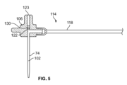
図2~4に示すように、カニューレアセンブリ70は、中空内部102を有するカニューレ74と、カニューレ74を担持するマニホルド106と、マニホルド106を担持するマニホルドガイド110とを含む。マニホルドガイド110、マニホルド106及びカニューレ74は、図2に示す第1の位置と図3に示す第2の位置との間で挿入機構筐体58に対して移動可能である。マニホルドガイド110及びマニホルド106は、第2の位置に配置されたときに筐体5の遠位端82に配置されている。マニホルド106は、カニューレ74の中空内部102と、図2~4のページ内へと延び且つ図5に示される流体経路コネクタ114とを流体的に接続するように構成されている。流体経路コネクタ114及びカニューレ74は、挿入機構54が起動されるとカニューレ74及び流体経路コネクタ114が筐体58に対して動くことができるようにマニホルド106に接続されている。流体経路コネクタ114は、マニホルド106の内部チャンバ122と流体連通する可撓性流体導管118を含む。可撓性流体導管118は、図1に示す無菌流体流路38の一部又は全体を画定し得る。図2及び4に示すように、筐体58のケーシング86に形成された垂直チャネル又は開口部126は、マニホルドガイド110及びマニホルド106が第1の位置と第2の位置との間を移動するときに流体経路コネクタ114及び可撓性流体導管118が筐体58に対して動くことを可能にする。
As shown in FIGS. 2-4,
図5では、マニホルド106は、マニホルド106の内部チャンバ122内に配置された隔壁130を含む。挿入機構54が突出前構成と挿入構成の両方にあるとき、トロカール66は隔壁130を貫通して配置される。トロカールアセンブリ62が第1の位置に戻ると、トロカール66は、筐体58に対して近位方向B(図2~4に示す)に移動し、それによってマニホルド106の近位端において内部チャンバ122、隔壁130、及び開口部123を通過する。隔壁130は、開口部123を閉じて密封するので、薬物送達中に流体が開口部123を通って逃げることができない。いくつかの実施形態では、カニューレアセンブリ70が第2の位置に配置されると、トロカール66が薬物送達中に無菌流体流路から隔離されるように、トロカール66は内部チャンバ112から完全に後退し得る。
In FIG. 5,
トロカールアセンブリ62は、トロカール66と、トロカール66を担持するハブ134と、挿入付勢部材138と、後退付勢部材142とを含む。ハブ134は、マニホルドガイド110に取り外し可能に接続され、挿入機構54が後退構成にあるとき、トロカールアセンブリ62が図4に示されるように第2の位置に後退することを許容するように、マニホルドガイド110から切り離される。トロカール66は、ハブ134が図2及び4に示す第1のハブ位置から図3に示す第2のハブ位置へ動くにつれてハブ134と一緒に動く。マニホルド106によって担持されているカニューレ74は、マニホルドガイド110と共に図2に示す第1の位置から図3に示す第2の位置へ移動し、挿入機構54が図4に見られるように後退構成にあるとき、第2の位置に留まる。トロカール66は、図2の突出前構成において、及びハブ134が第1のハブ位置から図3に示す第2のハブ位置に移動するときに、カニューレ74の中空内部102内に配置される。挿入機構54が挿入構成に配置されると、トロカール66及びカニューレ74は、筐体58の遠位端82の開口部98を通って延びる。トロカール66は、患者の皮膚12を貫いてカニューレ74の通路を作り出すように構成される。マニホルドガイド110が図3及び4に示されるように第2の位置にあるとき、マニホルドガイド110の底面146は、筐体58の遠位端82の内面150と直接接触し得る。マニホルドガイド110の底面146は、筐体58の遠位端82の内面150に当接し、それによって、トロカール66及びカニューレ74が筐体58の開口部98を通り患者の中へと移動することができる距離を制限する。トロカール66がそのストロークの終わりに達すると、それは患者の不快感を最小限にするために直ちに後退し得る。図4に示すように、ハブ134はマニホルドガイド110から切り離され、トロカール66は筐体58の内部空間90内に引き戻される。カニューレ74は薬物送達の間、第2の位置に対応する前進位置に留まる。
ハブ134は、中央部材154と、中央部材154を囲む第1の同心溝158と、第1の同心溝158から外側に離間した第2の同心溝162と、長手方向Aに対してハブ134の最も外側の部分を画定する変形可能タブ166a及び166bとを含む。図2~4に示されるように、ハブ134は、ハブ134の中央部材154の半径方向外側に配置された第1及び第2の変形可能なタブ166a及び166bを含む。中央部材154は、トロカール66を受け入れる孔172と、起動部材76と係合するように構成された近位部分176とを含む。第1の同心溝158は中央部材154に隣接し、ハブ134の遠位端184の第1のばね座180からハブの上面188を通って長手方向軸Aに沿って軸方向に延びる。第2の同心溝162は、ハブ134の近位端196の第2のばね座192からハブ134の底面200を通って延びる。第1の溝158及び第2の溝162は、内側ハブ壁204によって半径方向に隔てられ、第2の溝162は、内側ハブ壁204と第1及び第2の変形可能なタブ166a及び166bとの間に半径方向に配置される。そのように構成されるので、第2の溝162は第1の溝158の直径よりも大きい直径を有する。図2に示すように、挿入付勢部材138は最初に活性化状態で保持され、これは本実施形態では筐体58の近位端78とハブ134との間の挿入付勢部材138の圧縮構成に対応する。より詳細には、挿入付勢部材138は、活性化状態で、ハブ134の第1のばね座180と筐体58の頂部268との間で圧縮されている。同様に、後退付勢部材142は、最初に活性化状態で保持され、これは本実施形態では、ハブ134とマニホルドガイド110との間の後退付勢部材142の圧縮構成に対応する。より詳細には、後退付勢部材142は、ハブ134の第2のばね座192とマニホルドガイド110の上面208との間でその活性化状態で圧縮される。
図示の実施形態では、後退付勢部材142は第1のコイルばねによって画定され、挿入付勢部材138は第1のコイルばね内に同心円状に配置された第2のコイルばねによって画定されている。このバージョンでは、後退付勢部材142は、挿入付勢部材138の直径よりも大きい直径を有する。代替実施形態では、後退付勢部材142を画定するコイルばねは、挿入付勢部材138を画定するコイルばね内に同心円状に配置され得る。さらに別の代替実施形態では、挿入付勢部材138及び/又は後退付勢部材142は、加圧ガス機構、電気モータ、弾性膜、ねじりばね、板ばね、及び/又は挿入及び後退に関連する構成要素を動かすためのエネルギーを蓄積及び放出するための任意の他の適切な機構によって画定することができる。図示の実施形態に戻ると、挿入付勢部材138及び後退付勢部材142は、起動部材76が解放すると、挿入付勢部材138が遠位方向Cに軸方向に拡張し、それによってハブ134を第1のハブ位置から第2のハブ位置へ駆動するように配置される。図3において、挿入付勢部材138は拡張構成すなわち非活性化状態にあり、ハブ134は第2のハブ位置に配置されている。ハブ134が第1のハブ位置から第2のハブ位置へ移動するにつれて、マニホルドガイド110はハブ134の移動と同時に第1の位置から第2の位置へ駆動される。ハブ134及びマニホルドガイド110が(図3に示すように)筐体58の遠位端82に位置するそれぞれの第2の位置に達すると、切離し部材212がマニホルドガイド110及びハブ134を切り離し、後退付勢部材142がトロカール66を後退させるために近位方向Bに軸方向に拡張することを許容する。図4は、拡張状態又は部分的に非活性化状態にあり、ハブ134を筐体58の遠位端82から離れる方向に付勢し、ハブ134を第1のハブ位置に保持する後退付勢部材142を示す。図4に示すように、マニホルドガイド110はハブ134から切り離され、トロカール66はマニホルド106の内部チャンバ122から隔離される。
In the illustrated embodiment, the
取り外し可能に接続されているハブ134及びマニホルドガイド110は、挿入機構54が突出前構成から挿入構成に移行するときに、ユニットとして一緒に動く。ハブ134とマニホルドガイド110との共同移動は、ハブ134とマニホルドガイド110が切り離されるまで可能である。例示の実施形態では、第1及び第2の変形可能なタブ166a及び166bは、マニホルドガイド110とハブ134とを取り外し可能に接続し、マニホルドガイド110が第2の位置を占めると、切離し部材212と係合するように構成される。第1及び第2の変形可能なタブ166a及び166bのそれぞれは、マニホルドガイド110に形成された対応する第1又は第2の受入開口部216と係合する、又はこれと噛み合うように構成される。各変形可能なタブ166a及び166bは、幅広い遠位端224a、224bを有する可撓性本体220を含む。第1及び第2の受入開口部216は、第1及び第2の変形可能なタブ166a及び166bと整列され得る。図6及び7に示すように、各受入開口部216は、マニホルドガイド110の第1の肩部228及び第2の肩部230によって画定される。さらに、受入開口部216のそれぞれは、可撓性タブ166a、166bの可撓性本体220の幅WB以上であり、且つ変形可能なタブ166bの幅広い遠位端224bの幅WEよりも狭い幅WAを含む。マニホルドガイド110とハブ134とが接続されると、変形可能なタブ166bの遠位端224bがマニホルドガイド110の第1及び第2の肩部228、230の底面232に接触し、マニホルドガイド110の位置に対するハブ134の上方への垂直変位を制限する。
The detachably connected
図2及び4を参照し直すと、変形可能タブ166a及び166bの遠位端224a及び224bはそれぞれ、切離し部材212と係合するように構成された傾斜面237a又は237bを有するテーパ端部236a又は236bを含む。傾斜面237a及び237bのそれぞれは長手方向軸Aに対して非平行であり得、長手方向軸Aに対して90度未満の角度を形成する。変形可能なタブ166a及び166bの遠位端224a及び224bは、切離し部材212に対して摺動し、可撓性本体220をマニホルドガイド110に対して外側に拡張することによって変形させるように構成されてもよい。可撓性本体220がマニホルドガイド110の肩部228及び230から離れるように外方に撓むと、マニホルドガイド110はハブ134から切り離される。図2~4及び6に示すように、切離し部材212は、筐体58の遠位端82の両側に配置された傾斜部240a及び240bを含み得る。傾斜部240a及び240bは、それぞれ、傾斜面244a及び244bを有し得る。傾斜面244a及び244bは、それぞれ、変形可能タブ166a及び166bの傾斜面237a及び237bと係合するように構成されてもよい。傾斜部240a及び240bの傾斜面244a及び244bは、長手方向軸Aと非平行であり、長手方向軸Aに対して90度未満の角度を形成し得る。いくつかの実施形態では、傾斜面237a及び傾斜面244aは長手方向軸Aに対して同じ、又は実質的に同じ角度を形成し得る。同様に、傾斜面237b及び傾斜面244bは、長手方向軸Aに対して同じ又は実質的に同じ角度を形成し得る。したがって、傾斜面237a及び237bとそれらの対応する傾斜面244a及び244bとの面一な係合が可能であり得る。傾斜部240a及び240bの傾斜又は斜め面244a及び244bは、ハブ134が第1のハブ位置から第2のハブ位置に移動するにつれて、変形可能タブ166a及び166bを長手方向軸Aから離れるように半径方向外向きに変位させ得る。結果として、傾斜面244a及び244bは、変形可能タブ166a及び166bをマニホルドガイド110から分離することによって、ハブ134とマニホルドガイド110とを切り離し得る。傾斜部240a及び240bの傾斜面244a及び244bは、変形可能タブ166a及び166bが斜めの傾斜部240a及び240bの下方へ遠位方向Cに摺動するにつれてそれらを外方に押す。幅広い遠位端224a及び224bは、第1及び第2の肩部228、230の底面232から離れるように移動し、ハブ134がマニホルドガイド110から独立して移動することを可能にする。図6に示すように、筐体58に取り付けられていても一体的に形成されていてもよい切離し部材212の傾斜部240a及び240bは、マニホルドガイド110の開口部216内に嵌合するように寸法決めされてもよい。したがって、マニホルドガイド110が第2の位置を占めるとき、傾斜部240a及び240bは変形可能なタブ166a及び166bを変位する。
2 and 4, distal ends 224a and 224b of
図7は、可撓性本体220内に形成されたチャネル248を有する変形可能タブ166bを示す。チャネル248は、変形可能タブ166bが破断することなく外側に拡張することができるように可撓性本体220を変形させることができる。変形可能なタブ166bが外側に撓み、マニホルドガイド110の第1及び第2の肩部228及び230から切り離されると、変形可能なタブ166bは、図4に示すようにその元の形状に戻り得る。変形可能タブ166aは、変形可能タブ166bと同様の構造及び動作を有し得る。
FIG. 7 shows
本実施形態では、変形可能タブ166a及び166bはハブ134と一体的に形成されている。しかしながら、他の実施形態では、変形可能タブ166a及び166bは、マニホルドガイド110と一体的に形成されてもよい。挿入機構54は、例えば、接着剤又はメスとオスのキーとキースロット構成など、マニホルドガイド110とハブ134とを取り外し可能に接続するための接続部材を含み得る。さらに、切離し部材212は、筐体58内の異なる位置に配置されてもよい。いくつかの実施形態では、切離し部材212は、筐体58とは別の構成要素であり得る。切離し部材212は、ハブ134とマニホルドガイド110との接続部材を分離又はロック解除するように構成された係合面を含み得る。
In this embodiment,
図2~4を参照すると、筐体58は、筐体58の近位端78に位置する傾斜部260a及び260bを含むことができる。傾斜部260a及び260bはそれぞれ、変形可能なタブ166a及び166bが外側に広がらないように筐体58のケーシング86から内側に突出し得る。したがって、傾斜部260a及び260bは、挿入機構54が突出前構成を占めるときに、変形可能タブ166a及び166bとマニホルドガイド110との間の接続を確実にする一助となり得る。ハブ134が第1のハブ位置から第2のハブ位置に移動すると、変形可能タブ166a及び166bはそれらの対応する傾斜部260a及び260bを越えて摺動し得、続いてわずかに外側に広がる。変形可能タブ166a及び166bは、筐体58の遠位端82に配置された傾斜部240a及び240bのそれらの対応する傾斜面244a及び244bとよりよく係合するようにわずかに外側に拡張し得る。ハブ134が第2のハブ位置から第1のハブ位置へ近位方向Bに移動するとき、変形可能タブ166a及び166bは、それらが対応する傾斜部260a及び260bに接触するときに内側に撓み得る。
2-4,
起動部材76は、挿入付勢部材138がマニホルドガイド110及びハブ134を遠位方向Cに駆動することを可能にするように挿入付勢部材138を解放するように構成されている。図2~4に示すように、起動部材76は、筐体58に対して移動可能であり得、挿入付勢部材138が拡張するのを阻止又は防止するために、最初にハブ134の近位部分176と係合するように構成され得る。起動部材76は、挿入付勢部材138を解放するためにハブ134の近位部分176から外れるように構成されてもよい。図3を参照すると、起動部材76は、筐体58の上部268から延びるラッチタブ264、ラッチ本体272、及びラッチ本体272に形成された開口部276を含み得る。ラッチ本体272は、筐体58の上部268内に形成された窪み280内に配置され、窪み280の第1の端部284と窪み280の第2の端部288との間で摺動するように構成されている。図2に示す突出前構成において、ラッチタブ264は窪み280の第1の端部284に配置され、ラッチ本体272はハブ134の中央部材154に形成された溝292と接触する。起動部材76が解放/突出されると、ラッチ本体272は溝292から離れる方向に移動し、ハブ134の近位部分176との接触から外れる。ラッチ本体272は、窪み280の第2の端部288に摺動してハブ134の近位部分176がラッチ本体272の開口部276を通って摺動することを許容するように構成される。図3において、ラッチ本体272は窪み280の第2の端部288に配置され、ハブ134の中央部材154の溝292から外れる。いくつかの実施形態では、挿入機構54の起動部材76は、患者又は医療提供者によるアクチュエータ28の手動による移動が挿入機構54を起動し得るようにアクチュエータ28に機械的に接続され得る。他の実施形態では、起動部材76の移動は、患者又は医療提供者によるアクチュエータ28の移動に応答して制御装置26によって操作される電気機械的手段によって達成されてもよい。
図7は、筐体58のケーシング86を除いた、後退構成にある挿入機構54を示す。後退付勢部材142は、ハブ134及び挿入付勢部材138を付勢して、ハブ134を第1のハブ位置に維持する。マニホルドガイド110は、マニホルドガイド110が第1の位置と第2の位置との間を移動するときに流体コネクタ118がマニホルド106と流体連通状態を維持することを可能にするための開口部を含み得る。後退付勢部材142は、ハブ134の第2のばね座192とマニホルドガイド110との間に配置されている。ハブ134の近位部分176は、筐体58の上部268の開口部94及び開口部276を通って延びている。後退構成では、ハブ134の近位部分176は起動部材76のラッチ本体272と係合しておらず、トロカールアセンブリ62の第2の起動又は展開の前に突出前構成にリセット又は再構成されてもよい。筐体58の近位端78に位置する上部268は、複数の締結具296によって筐体58のケーシング86に固定されてもよい。
FIG. 7 shows the
以下に記載するのは、図2~7に示す挿入機構54を組み込む図1に示す薬物送達装置などの薬物送達装置を操作する方法の一実施形態である。この方法は、患者又は医療提供者(例えば、介護者、看護師、医師等)に装着型薬物送達装置10を提供することで開始し得る。次に、患者又は医療提供者は、薬物送達装置10の底壁36を患者の皮膚12へ接着又は一時的に取り付けるために薬物送達装置10の底壁36を患者の皮膚12と接触するように配置し得る。挿入機構54を起動させるために、患者又は医療提供者はアクチュエータ28を押し下げることができ、次にアクチュエータ28が起動部材76を変位し得、それにより起動部材76がハブ134を離脱又は解放するようにする。結果として、挿入付勢部材138は、挿入機構筐体58の長手方向軸Aに沿って遠位方向Cに拡張することを許容され得る。そのような拡張は、ハブ134、トロカール66、マニホルドガイド110、及びカニューレ74を第1の位置から第2の位置へと駆動し、それによってトロカール66を患者の皮膚12に貫入させ、患者の内側にカニューレ74を導入する。
Described below is one embodiment of a method of operating a drug delivery device, such as the drug delivery device shown in FIG. 1, incorporating the
その後、ハブ134をマニホルドガイド110から切り離して、後退付勢部材142が長手方向軸Aに沿って近位方向Bに拡張することを許容することができる。このような拡張により、トロカール66及びハブ134が第2の位置から第1の位置へ後退される一方、マニホルドガイド110、マニホルド106、及びカニューレ74は第2の位置に保持される。したがって、カニューレ74の遠位端を患者の内側に残したまま、トロカール66を患者から取り除くことができる。カニューレ74の挿入に続いて、又はそれと同時に、この方法は、(a)容器アクセス機構29を起動させて容器針31を隔壁32を通して挿入し、容器14と流体コネクタ22の無菌流体流路38との間の流体連通を確立すること、及び(b)患者への送達のために駆動機構24を起動させて薬物46を容器14から流体経路コネクタ22を介してカニューレ74内に放出することを含み得る。図28及び29に示す別の例では、トロカール66は、流体通路コネクタ22に直接接続される中空針67で置き換えられてもよい。この場合、挿入機構54は、容器14への流体接続のためのマニホルド106を含まなくてもよい。代わりに、流路119が、薬物46をカニューレ74内に分配するように構成された中空針67のかかりのある端部73に直接接続される。操作中、マニホルド106と同様であり得るカニューレガイド107が、薬物送達のために、カニューレ74をハブ134と共に第2の位置へ搬送し、ハブ134が初期ハブ位置に戻るときに第2の位置に留まる。この時点で、中空針67は流路119を介してカニューレ74を流体経路コネクタ22に流体接続し得、薬物46は中空針67を通って、カニューレ74を通って、そして患者の体内に放出され得る。カニューレガイド107内の中空針67の外径の周りに、Oリングなどのシール71が配置されて、流体送達のための密封経路125を提供する。カニューレガイド107は、マニホルドガイド110のようにハブ134に取り外し可能に接続されてもよく、又はカニューレガイド107は別の機構によってハブ134に取り外し可能に接続されてもよい。いくつかの実施形態では、挿入機構54、容器アクセス機構29、及び/又は駆動機構24を起動させることは、アクチュエータ28を一回押すことによって達成することができる。
図8~13において、本開示の別の実施形態による挿入機構354が示されている。挿入機構354は、マニホルドガイド410がハブ434に接続及び切り離される方法を除いて、上述の挿入機構54と類似している。挿入機構54の要素に類似する図8~13の挿入機構354の要素は、300を加えた同じ参照番号で示されている。これらの要素の多くの記載は、簡潔さのために省略されるかさらには排除されている。さらに、挿入機構354は、図1に示す薬物送達装置10などの薬物送達装置に組み込まれてもよい。
8-13, an
図8~13を参照すると、挿入機構354は、図8~11に示す切離し部材512a又は図12及び13に示す切離し部材512bのいずれかを含み得る。切離し部材の他の構成もまた可能である。図示の実施形態では、筐体358は、マニホルドガイド410とハブ434とを切り離すために筐体358の遠位端382に配置された傾斜部を含まなくてもよい。図8~11に示す実施形態では、切離し部材512aは、筐体358の遠位端382に配置された回転板600を含み、カニューレ及びトロカールアセンブリ362及び370が挿入構成に置かれると、長手方向軸Aを中心に方向Dに回転するように構成される。回転板600は、変形可能なタブ466a及び466bの数に対応するスロット602a及び602bを含み、ここで各スロット602a及び602bは対応する変形可能タブ466a及び466bと整列している。各スロット602a及び602bは、回転板600の外周608の近くに配置されている第2の端部606a及び606bに対して内側に配置されている第1の端部604a及び604bを有する。ハブ434の各変形可能タブ466a及び466bは、変形可能タブ466a及び466bの遠位端524a及び524bから下方に延びるピン598a及びピン598bを含む。図8に示す突出前構成では、ピン598a及び598bは、スロット602a及び602bの第1の端部604a及び604bと整列している。図9及び10に示す挿入形態では、マニホルドガイド410が第2の位置を占め、ピン598a及び598bが第1の端部604a及び604bでスロット602a及び602b内に配置されている。
8-13, the
マニホルドガイド410とハブ434を切り離すために、回転板600は、図10に示す第1の位置から図11に示す第2の位置へ長手方向軸Aを中心にして方向Dに回転される。板600は、マニホルドガイド410に対して回転し、スロット602a及び602bに受容された変形可能タブ466a及び466bを変形させて、マニホルドガイド410とハブ434を切り離す。回転中、各ピン598a及び598bがそれぞれのスロット602a及び602bに沿って第1の端部604a及び604bから第2の端部606a及び606bへ摺動するにつれて、変形可能タブ466a及び466bはマニホルドガイド410に対して回転板600の外周608に向かって外側に押される。回転板600は、マニホルドガイド410の第1及び第2の肩部528及び530からピン598a及び598bを介して変形可能タブ466a及び466bを効果的に押して、マニホルドガイド410とハブ434を切り離す。マニホルドガイド410及びハブ434が切り離されると、後退付勢部材442が近位方向Bに拡張してトロカールアセンブリ362を後退構成に後退させ得る。
To disconnect
トロカール及びカニューレアセンブリ362及び370が図9及び10に示す挿入構成を占めると、板600を回転させることによって回転板600を起動させることができる。挿入構成では、トロカール366及びカニューレ374は、回転板600に形成された中央開口部610を通り、且つ筐体358の遠位端382の開口部を通って配置される。トロカールアセンブリ362を後退させるために、回転板600は、筐体358の閉鎖部分390の外側に配置されたタブ609を介してD方向に回転させることができる。板が第1の位置から第2の位置へ回転する600につれ(これは図11及び12のタブ609の位置の変化によって見ることができる)、スロット602a及び602bは、変形可能タブ466a及び466bを押し出し、マニホルドガイド410及びハブ434を切り離す。カニューレ374及びトロカール366が筐体358の遠位端382を介して挿入/配置されるのと同時に又はその直後に、回転板600を回転するように起動又はトリガしてもよい。別の実施形態では、回転板600は自動的にはトリガされず、代わりに挿入機構354の挿入動作と後退動作を分離するために独立してトリガされてもよい。回転板600のタブ609は、図1の薬物送達装置10の主筐体30の外側からアクセス可能な第2のアクチュエータに結合され得る。第2のアクチュエータは、患者又は医療提供者によって起動され得る押下可能なボタン又は線形起動機構とすることができる。別の実施形態では、タブ609は、トロカールアセンブリ362の後退及び回転板600の回転が挿入とは無関係にトリガされるように、装置10内の別の連結システムに結合される。他の例では、図28及び29に示す例と同様に、トロカール366は、流体経路コネクタ22に直接接続されている中空針で置き換えられてもよい。この場合、挿入機構354は、容器14に流体接続するためのマニホルド406を含まなくてもよい。代わりに、流路は、薬物46をカニューレ374内に分配するように構成された中空針に直接接続される。操作中、マニホルド406及びマニホルドガイド410と同様に配置されたカニューレガイド(例えば、図28及び29のカニューレガイド107)は、薬物送達のためにハブ434と共にカニューレ374を第2の位置に搬送し、ハブ434が初期ハブ位置に戻ると第2の位置に留まる。この時点で、中空針は、カニューレ374を流体経路コネクタ22に流体接続することができ、薬物46は、中空針を通って、カニューレ374を通って、そして患者の体内に放出され得る。Oリングなどのシールが、カニューレガイド内の中空針の外径の周りに配置されて、中空針からカニューレへの流体送達のための密封された経路を提供する。中空針を通して薬物を分配することは、自動的に又は手動で起動させることができる。
With trocar and
図12、13、26、及び27に示す代替実施形態では、切離し部材512bは、筐体358の遠位端382に配置され、長手方向軸Aに向かって摺動して変形可能タブ466a及び466bと係合してマニホルドガイド410とハブ434を切り離すように構成された摺動プレート612を含む。摺動プレート612は、マニホルドガイド410が第2の位置を占めるのと同時に又はそのすぐ後に、摺動プレート612が図13に示す係合位置に摺動すると、変形可能タブ466a及び466bを変位させるように構成されたテーパアーム614a及び614bを有するU字形である。そのように構成されると、マニホルドガイド410が第2の位置を占めるとき、摺動プレート612は、マニホルドガイド410に向かって筐体358の閉鎖部分390の中に押し込まれ得る。ハブ434が第2のハブ位置を占めるとき、ピン598a及び598bはアーム614a及び614bの斜めの端部616a及び616bと接触し、変形可能タブ466a及び466bは長手方向軸Aから外側に押し出される一方、テーパアーム614a及び614bは方向Eに摺動する。摺動プレート612が係合位置に摺動すると、斜めの端部616a及び616bはピン598a及び598bをマニホルドガイド410の肩部528及び530との係合から遠ざける。長方形の開口部611が筐体358の遠位端382内に形成され、摺動プレート612が、図12、26、及び27に示される非係合位置から、図13に示す係合位置へ移動することを可能にする。摺動プレート612は、トロカールアセンブリ362及びカニューレアセンブリ370が挿入構成を占める前又は後に摺動プレート612が変形可能タブ466a及び466bと係合するように係合位置に押し込まれてもよい。挿入機構354は、摺動プレート612が係合位置に押し込まれたとき、及び薬物送達の直前に、自動的に後退するように構成されてもよい。別の実施形態では、トロカールアセンブリ362及びカニューレアセンブリ370が挿入構成を占めた後のある時に摺動プレート612を係合位置に押し込んで、後退を遅らせることができる。
In an alternative embodiment shown in FIGS. 12, 13, 26, and 27,
図26及び27は、筐体358のロックタブ618と負荷ばね620との間の非係合位置に保持された摺動プレート612を示している。ロックタブ618が変形可能であり、摺動プレート612から離れると、負荷ばね620は摺動プレート612を係合位置に追いやる。負荷ばね620は、薬物送達装置10の内壁622と摺動プレート612の後部619との間で筐体358の外側に配置される。内壁622は、薬物送達装置10の壁30又は筐体30内に配置され挿入機構筐体358に対して近位に配置された別の壁、障壁、若しくは剛性構造であり得る。ロックタブ618は、筐体358の底面450から内部空間390内に延び、摺動プレート612の中央部分624と係合する。マニホルドガイド410が第2の位置に移動するときにロックタブ618が中央部分624との係合から外れるように押されると、負荷ばね620が解放される。具体的には、マニホルドガイド410が第2の位置に移動すると、マニホルドガイド410の底面446がロックタブ618と接触し、ロックタブ618を遠位方向Cに押す。ロックタブ618は、摺動プレート612の中央部分624に形成された斜めの表面625を越えて摺動し、中央部分624との係合から外れるようにC方向に移動する。同時に、又はそれに続いて、負荷ばね620は、摺動プレート612を係合構成に押し込むために方向Eに延びる。図示の例では、ロックタブ618は筐体358の底面450に成形されている。別の実施形態では、摺動プレート612は、マニホルドガイド410が第2のマニホルド位置を占めるときに変位する別の手段によって負荷ばね620に抗して保持され得る。さらに別の実施形態では、摺動プレート612は、摺動プレート612をE方向に押すためにマニホルドガイド410によってトリガされる別の機構によって係合位置に付勢されるか、別の方法で追いやられてもよい。これは、摺動プレート612を係合構成に押し込むための摺動プレート612の自動起動の一例であり、他の適切な起動機構が使用されてもよい。時間遅延を達成するために、機械式時計機構又は電気機械ソフトウェア制御を薬物送達装置に組み込んでもよい。
26 and 27
図14~18を参照すると、挿入機構654の別の実施形態が示されている。挿入機構654は、マニホルドガイド710がハブ734に接続及び切り離される方法を除いて、上述の挿入機構54と同様である。挿入機構54の要素と同様である図14~18に示される挿入機構654の要素は、600を加えた同じ参照番号によって示される。これらの要素の多くの記載は、簡潔さのために省略されるか、さらには排除される。さらに、挿入機構654は、図1に示す薬物送達装置10などの薬物送達装置に組み込まれてもよい。
14-18, another embodiment of an
図14~18に示されるように、マニホルドガイド710は、ハブ734に対して回転可能であり得る。ハブ734は、タブ766a及び776bの遠位端824a及び824bに配置されたフック837a及び837bを有する剛性タブ766a及び766bを含む。フック837a及び837bは、マニホルドガイド710の第1及び第2の肩部828及び830と動作可能に結合され、ハブ734とマニホルドガイド710とを接続する。フック837a及び837bは、マニホルドガイド710の第1及び第2の肩部828及び830の底面832に係合し、それにより、挿入機構654が起動されるとマニホルドガイド710がフック837a及び837bを介してハブ734を効果的に引っ張るようになっている。剛性タブ766a及び766bのフック837a及び837bがマニホルドガイド710の第1及び第2の肩部828及び830から切り離されると、ハブ734とマニホルドガイド710とが切り離される。図示の実施形態では、マニホルドガイド710がハブ734に対してD方向に回転すると、ハブ734及びマニホルドガイド710が切り離され、剛性タブ766a及び766bのフック837a及び837bを肩部828及び830の底面832の下から外へ移動させる。
As shown in FIGS. 14-18,
切離し部材812は、筐体658の遠位端682に配置された解放ピン840a及び840bを含み得る。各ピン840a及び840bは、マニホルドガイド710の開口部816と整列され得る。開口部816のそれぞれは、第1の肩部828と第2の肩部830との間の空間によって画定される。図16~18に示すように、開口部816のそれぞれは、第1の肩部828の斜めの内縁部917と第2の肩部830の直線状の内縁部918とによって画定される非対称断面を有する。内縁部917及び918は、さらに、上端部922からオフセットされた開口部の底端部920を画定する。解放ピン840a及び840bは、開口部816の斜めの内縁部917と一致するように斜めのテーパ状端部844a及び844bを含む。マニホルドガイド710及びハブ734が第1の位置から第2の位置へ移動すると、ピン840a及び840bのテーパ状端部844a及び844bは、開口部816の底端部902に入り、斜めの内面917に対して摺動する。図17及び図18において、マニホルドガイド710が第2の位置に向かって移動し、マニホルドガイド710の肩部830を剛性タブ766bのフック837bとの接触から離れるように回転させるか、又はスライドさせる。挿入機構654が図18に示される後退構成にあるとき、ピン840a及び840bは開口部816を通って配置され、マニホルドガイド710はハブ734との接続から外れて回転し、後退付勢部材742は拡張し、ハブ734は第1のハブ位置にある。図14~18のそれぞれには示されていないが、起動部材は、前の実施形態に示した起動部材と同じでも異なっていてもよい。
図19及び20は、挿入機構954のさらに別の実施形態を示す。挿入機構954は、マニホルドガイド1010がハブ934に接続され且つ切り離される方法を除いて、上述の挿入機構54と類似している。挿入機構54の要素に類似する図19及び20に示される挿入機構954の要素は、900を加えた同じ参照番号で示されている。これらの要素の多くの記載は、簡潔さのために省略されるか又は排除される。さらに、挿入機構954は、図1に示す薬物送達装置10などの薬物送達装置に組み込まれてもよい。
19 and 20 show yet another embodiment of an
図19及び20に示されるように、本明細書では保持部材とも呼ばれるばね付勢された保持部材1220a及び1220bが、ハブ1034とマニホルドガイド1010とを接続するように最初に変形可能タブ1066a及び1066bを保持するために各変形可能タブ1066a及び1066bに提供される。各保持部材1220a及び1220bは、マニホルドガイド1010の外側部分1222とハブ1034の変形可能タブ1066a及び1066bとの間に配置される。変形可能タブ1066a及び1066bは、最初、マニホルドガイド1010の肩部1028及び1030と接触している。図19に示す突出前構成では、保持部材1220a及び1220bはそれぞれ、保持部材1220a及び1220がそれぞれ変形可能タブ1066a及び1066bと接触する第1の回転位置にばね付勢されてもよい。結果として、変形可能タブ1066a、1066bは、変形可能タブの遠位端1124a及び1124bがマニホルドガイド1010の肩部1028及び1030の斜めの底面1032a及び1032bと係合する位置に保持されてもよい。保持部材1220a及び1220bは、最初、変形可能タブ1066a及び1066bをマニホルドガイド1010に対して保持し、それによって、後退付勢部材1042によって提供される付勢力の結果として変形可能タブ1066a及び1066bがマニホルドガイド1010に対して外側に広がるのを防止又は阻止する。したがって、保持部材1220a及び1220bは、マニホルドガイド1010がハブ1034から時期尚早に切り離されることを防止し得る。マニホルドガイド1010が第2の位置に移動すると、保持部材1220a及び1220bはマニホルドガイド1010と共に移動して、切離し部材1112が保持部材1220a及び1220bに係合するまで、変形可能タブ1066a及び1066bを保持する。
As shown in FIGS. 19 and 20, spring-biased
図20は、切離し部材1112が保持部材1220a及び1220bと係合してマニホルドガイド1010及びハブ1034を切り離す時点を示す。切離し部材1112は、筐体958の遠位端982に配置されたピン1140a及び1140bを含み、各ピン1140a及び1140bは、マニホルドガイド1010又はハブ1034と直接係合することなく保持部材1220a及び1220bの一方と係合するように整列される。ピン1140a及び1140bは、挿入付勢部材1038がそのストロークの終わりに到達する前及びマニホルドガイド1010が第2の位置に到達する前、保持部材1220a及び1220bと係合する。この瞬間に示されるように、ピン1140a及び1140bは、保持部材1220a及び1220bを変形可能タブ1066a及び1066bから離れる方向Hに第2の回転位置まで回転させる。この第2の回転位置では、保持部材1220a及び1220bは、変形可能タブ1066a及び1066bがマニホルドガイド1010から離れるのに十分な隙間を提供し、それによってマニホルドガイド1010をハブ1034から切り離すことができる。変形可能タブ1066a及び1066bの遠位端1124a及び1124bは、変形可能タブ1066a及び1066bが、マニホルドガイド1010の肩部1128及び1130の斜めの底面1132a及び1132bとの接触から滑り出ることを可能にする傾斜した表面1137a及び1137bを有する。マニホルドガイド1010の斜めの底面1032a及び1032bは、長手方向軸Aと非平行であり、長手方向軸Aに対して90度未満の角度を成し得る。いくつかの実施形態では、傾斜面1137aと傾斜面1032aは長手方向軸Aに対して同じ又は実質的に同じ角度を成し得る。同様に、傾斜面1137bと斜めの底面1032bとは長手方向軸Aに対して同じ又は実質的に同じ角度を成し得る。したがって、傾斜面1137a及び1137bとそれらの対応する斜めの底面1032a及び1032bとの面一係合が可能であり得る。いくつかの実施形態では、ばね保持部材1220a及び1220bは、保持部材1220a及び1220bがピン1140a及び1140bと係合するときに解放ピン1140a及び1140bに抗して付勢するばねロックを含み得る。各保持部材1220a及び1220bのばね力は、挿入付勢部材1038のばね力によって克服されるので、保持部材1220a及び1220bを回転させるための制限された抵抗がある。他の実施形態では、ばね保持部材1220a及び1220bは、解放ピン1140a及び1140bによって変位させられたときに変形可能タブ1066a及び1066bを解放するために方向Hに回転するヒンジドアであってもよい。
FIG. 20 shows when disconnecting
図21~図25を参照すると、挿入機構2054の別の実施形態が示されている。挿入機構2054は、マニホルドガイド2010がハブ2034に接続され切り離される方法を除いて、上述の挿入機構54と同様である。また、挿入機構54に関連して使用されるものと比較して、トロカール及びカニューレアセンブリ2062及び2070におけるいくつかの構造的変形がある。挿入機構54の要素と同様である図21~25に示される挿入機構2054の要素は、2000を加えた同じ参照番号が示されている。これらの要素の多くの記載は、簡潔さのために省略又は排除さえされている。さらに、挿入機構2054は、図1に示す薬物送達装置10などの薬物送達装置に組み込まれてもよい。
21-25, another embodiment of an
カニューレアセンブリ2070は、カニューレ2074、マニホルド2106を支持するマニホルドガイド2110、変形可能なリング2300、及び挿入付勢部材2138を含む。トロカールアセンブリ2062は、トロカール2066、トロカール2066を支持するハブ2134、及び後退付勢部材2142を含む。ハブ2314は、その近位端2196で溝2292によって画定されたフランジ付きノブ2176と、遠位端2197に配置された環状チャネル2158とを含む。フランジ付きノブ2176は、後退付勢部材2142に結合される。ハブ2134は、変形可能なリング2300を介してマニホルドガイド2110に取り外し可能に接続され、変形可能なリング2300は、トロカール2066及びカニューレ2074が筐体2058の開口部2098を通して挿入された後に、マニホルドガイド2110からハブ2340を切り離し、トロカールアセンブリ2062が後退することを可能にするように変形する。挿入機構2054が図21の突出前構成及び図22の挿入構成を占めるとき、変形可能なリング2300はマニホルドガイド2110と共に動く。マニホルドガイド2110は、突出前構成において筐体2058と係合し、挿入機構2054が起動されると筐体2058から切り離されて挿入付勢部材2138を解放するように構成された変形可能タブ2166a及び2166bを含む。図21及び22は、明確にするために挿入機構2054を部分的にしか示していない。
図21に示す突出前構成では、後退付勢部材2142は、最初、ハブ2134と筐体2058の近位端2078との間に非活性化状態で保持される。挿入付勢部材2138は、最初、筐体2058の近位端2078とマニホルドガイド2110との間に活性化状態で保持される。より具体的には、後退付勢部材2142は、筐体2058の上部2268及び挿入付勢部材2138に隣接する外側部分2306を有するばねディスクである。挿入付勢部材2138はコイルばねであり、特にばねディスク2142の外側部分2306と変形可能なリング2300との間に保持される。変形可能なリング2300は、挿入付勢部材2138とマニホルドガイド2110の上面2208との間に保持される。別の実施形態では、コイルばね2138は、筐体2268の上部とマニホルドガイド2110の上面2208との間に保持されてもよく、ここで、ばねディスク2142の外側部分2306は筐体2058の上部2268に固定され、変形可能なリング2300の外縁2314はマニホルドガイド2110の上面2208に固定される。この実施形態における挿入機構2054は、2つではなく1つの活性化された付勢部材を提供することによって挿入機構2054の組み立てを容易にし得る。
21,
図21、22、及び23を参照すると、フランジ付きノブ2176は、ハブ2134の溝2292をばねディスク2142の中央部分2302と接続するために、ばねディスク2142の中央開口部2304を通って配置されている。挿入付勢部材2138が解除されると、挿入付勢部材2138はハブ2134を図21の第1のハブ位置から図22の第2のハブ位置へ付勢する。ハブ2134がばねディスク2142の中央部分2302を遠位方向Cに下方に引っ張ると、ばねディスク2142は活性化されるようになる。図22に示すように、ばねディスク2142の外側部分2306は筐体2058の上部2268に隣接したままであり、ばねディスク2142の渦巻2308は挿入付勢機構2138のばねコイル内に部分的に配置されている。マニホルドガイド2110が第1の位置から第2の位置に移動すると、マニホルドガイド2110とハブ2134が切り離されてばねディスク2142がその非活性化状態に戻るまで、ばねディスク2142は次第に活性化されるようになる。
21, 22 and 23,
図21、22及び24に示されるように、カニューレアセンブリ2070の変形可能なリング2300は、挿入付勢部材2138とマニホルドガイド2110の上面2208との間に配置される。第1及び第2の係合アーム2310a及び2310bは、変形可能なリング2300の外縁2314から延びる。外縁2314は、挿入付勢部材2138のためのばね座を提供し、係合アーム2310a及び2310bの遠位端2316a及び2316bは、ハブ2134の円周面2159の曲率と一致するように成形される。図21の突出前構成において、係合アーム2310a及び2310bの遠位端2316a及び2316bは、チャネル2158内に配置され、ハブ2134の円周面2159に接触する。変形可能なリング2300の第1及び第2の脚部2312a及び2312bは、ばね座の反対の側から下方に延び、マニホルドガイド2110に形成された開口部2216a及び2216b内に配置される。開口部2216は、マニホルドガイド2110の上面2208から底面2142を通って延び、脚部2312a及び脚部2312bの軸方向移動に十分な幅を有する。変形可能リング2300は、様々な挿入機構の要件を満たすように所望の用途に従ってカスタマイズされてもよい。例えば、異なる実施形態は、変形可能なリングとハブとをよりよく把持又は接続するために好ましい厚さを有する2つ以上の係合アームを含み得る。さらに別の実施形態では、変形可能なリングの材料は、挿入付勢部材2138のばね力、後退付勢部材2142のばね力、ハブ2134の構成、及び/又はマニホルドガイド2110の構成に基づいて決定されてもよい。
As shown in FIGS. 21, 22 and 24,
突出前構成では、脚部2312a及び2312bは、マニホルドガイド2110が第2の位置を占めるまでオフセット距離xだけマニホルドガイド2110の底面2146を越えて延びる。したがって、脚部2312a及び2312bは、マニホルドガイド2110が第2の位置を占める前、筐体2058の底面2150に接触する。マニホルドガイド2110が距離xを移動して第2の位置を占めると、筐体2058の底面2150が脚部2312a及び2312bに十分に衝撃を与え、変形可能なリング2300を変形させてマニホルドガイド2110及びハブ2134を切り離す。図21と比較すると、図22に示される脚部2312a及び2312bは、近位方向Bにオフセット距離xに位置し、筐体2058の底面2150と接触している。変形可能リング2300の外縁2314とマニホルドガイド2110との剛性接触と組み合された開口部2216a及び2216b内の脚部2312a及び2312bの軸方向の動きは、係合アーム2310a及び2310bを変形させ、チャネル2153から離れてH方向に曲げる。変形中、係合アーム2310a及び2310bは、ハブ2134に対して半径方向外向きに拡張し、ハブ2134をマニホルドガイド2110から切り離す。カニューレアセンブリ2070が後退されると、変形可能なリング2300は、マニホルドガイド2110の上面2208と挿入付勢部材2138との間に留まる。別の実施形態では、変形可能なリング2300は、マニホルドガイド2110の開口2316a及び2316bを介して配置される脚部2312a及び2312bを含まなくてもよい。むしろ、マニホルドガイド2110が第2のマニホルド位置に達すると、変形可能なリング2300はなおも変形して、ハブ2134をマニホルドガイド2110から切り離し得る。さらに別の実施形態では、変形可能なリング2300の形状及び材料特性は、所望のリリースポイントにおいて後退付勢部材2142の後退力が係合アーム2310a及び2310bとハブ2134のチャネル2158との間の係合力に打ち勝つように調整されてもよい。
In the pre-extruded configuration,
次に、起動部材2076について、図21及び25を参照して記載する。マニホルドガイド2110の上方に延びる変形可能タブ2166a及び2166bは、筐体2058の上部2268を通して配置されたそれぞれの遠位端2224a及び2224bを含む。図25では、マニホルドガイド2110は、等間隔に配置された3つの変形可能タブを含み、変形可能タブの遠位端2224a、2224b、2224cは、筐体2058の上部2268に形成された3つの対応する開口部2318a、2318b、2318cを介して配置されている。遠位端2224a、2224b、及び2224cの傾斜面2237a、2237b、及び2237cは、筐体2058の上部2268に引っ掛かるか係合するように形成されており、突出前構成においてマニホルドガイド2110と筐体2058とを接続する。この実施形態では、起動部材2076は、レバー2324によって作動又はトリガされると方向Jに回転するカム2320を含む。カム2320は、カムが120度回転すると変形可能なタブの遠位端2224a、2224b、及び2224cに対して摺動するように成形されたクリップされた端部2326a、2326b、及び2326c以外、三角形の形状を全体的に有する。カム2320のクリップされた端部2326a、2326b、及び2326cが変形可能なタブの遠位端2224a、2224b、及び2224cに対して摺動すると、変形可能なタブは方向Kに外向きに押され、遠位端2224a、2224b及び2224cを筐体2058の上部2268から係合解除し、これらは、対応する開口部2318a、2318b、及び2318cを介して落下する。遠位端2224a、2224b、及び2224cが筐体2058の上部2268から一掃されると、挿入付勢部材2138は解放され、マニホルドガイド2110を遠位方向Cに移動させる。レバー2324は図1の薬物送達装置10の主筐体30の外部からアクセス可能なアクチュエータ28からの結合された動きによって回転されてもよい。一実施形態では、アクチュエータ28は、患者が薬物送達装置10の筐体30の外面を横切ってボタンをスライドさせてレバー2324を起動させることを可能にする線形起動スイッチであり得る。別の実施形態では、アクチュエータ28は、ボタンが押されるとレバーを方向Jに押すばね式キャッチを解除するように構成された押しボタンであり得る。装置10を患者に取り付ける前のボタンの偶発的な圧縮/解放を回避するために、装置10が患者に物理的に適用されるまで、ばね式キャッチは最初にロックされてもよい。機械式の身体装着型センサは、身体装着型センサによって装置10の物理的適用が感知されると、ばね式キャッチをロック解除し得る。
本明細書に記載の方法及び機構は、より単純な設計、信頼性の向上、患者の不快感及び不安の低減、精度の向上、並びに製造のコスト及び時間の低減など、既知の挿入装置に勝る利点を提供する。特に、本開示の挿入機構54、354、654、954、及び2054は、多くの異なる装着型薬物送達装置での使用に容易に適合され得、特定の患者集団に対してカスタマイズされ得る。挿入機構54、354、654、954、及び2054は、異なる駆動機構、異なる形態、及び異なる薬物を有する多種多様な装着型薬物送達装置に実装されてもよい。挿入機構54、354、654、954、及び2054、特にトロカールアセンブリ62、362、662、962、及び2062並びにカニューレアセンブリ70、370、670、970、及び2070の動作は、駆動機構24、起動部材76、376、若しくは2076、又は薬物送達装置10の形態によって動作又は機能において限定されない。さらに、挿入機構54、354、654、954、及び2054は、特定の患者及び患者集団の痛みを最小化するように適合又はカスタマイズされてもよい。例えば、トロカールアセンブリ62、362、662、962、及び2062とカニューレアセンブリ70、370、670、970、及び2070の第1の位置と第2の位置との間の移動距離を最小化することができる。さらに、挿入付勢部材138、438、738、1038、及び2138のばね力、マニホルドガイド110、410、710、1010、及び2110の質量、及び/又はマニホルド106、406、706、1006、及び2106の質量は、患者に加えられる挿入衝撃力を低減するために減少されてもよい。
The methods and mechanisms described herein are superior to known insertion devices, including simpler design, improved reliability, reduced patient discomfort and anxiety, improved accuracy, and reduced cost and time to manufacture. provide an advantage. In particular, the
図2~20に示される実施形態では、後退付勢部材のばね力に対する挿入付勢部材のばね力の比は、約(例えば、±10%)0.77であり得る。さらに、これらの実施形態では、挿入付勢部材138、438、738、及び1038は、約(例えば、±10%)4N~15Nの範囲のばね力を有し得、後退付勢部材142、442、742及び1042は、約(例えば、±10%)6N~35Nの範囲のばね力を有し得、これは、約(例えば、±10%)0.01秒以下の挿入時間、約(例えば、±10%)8mmの注入深さ、及び約(例えば、±10%)25mmの合計装置高さを達成し得る。図21~25に示される実施形態では、挿入付勢部材のばね力に対する後退付勢部材のばね力の比は、約(例えば、±10%)0.77であり得る。挿入付勢部材2138は、約(例えば、±10%)4N~15Nの範囲のばね力を有し得、後退付勢部材2142は、約(例えば、±10%)2N~12Nの範囲のばね力を有し得、これは約(例えば、±10%)0.01秒以下の挿入時間、約(例えば、±10%)8mmの注入深さ、及び約(例えば、±10%)25mmの合計装置高さを達成し得る。
In the embodiment shown in FIGS. 2-20, the ratio of the spring force of the insertion biasing member to the spring force of the retraction biasing member can be about (eg, ±10%) 0.77. Further, in these embodiments, the
挿入機構54、354、654、954、及び2054はまた、患者の快適性を高め、潜在的な患者の不安を軽減し得る。例えば、挿入機構54、354、654、954、及び2054は自動的に動作し、トロカールアセンブリ62、362、662、962、及び2062は、カニューレ74、374、674、974、又は2074を患者に挿入した後、ほとんど遅延なくトロカール66、366、666、966又は2066を後退させるように構成されてもよく、トロカールが患者の体内に配置される時間を最小化する。従来の方法及び機構では、患者は、ボタンを装置内に進めるにつれてトロカール又は剛性針を自分自身に挿入することを要求され得る。このタイプの挿入機構は、患者がボタンの前進によりトロカールの挿入を制御しているため、患者への不安や威嚇の原因になり得る。さらに、既知の方法と機構は、患者が装着型装置を取り外しているときに患者の皮膚内に留まる可能性のある外部安全ガードと組み合わされた剛性針を含む。対照的に、開示された装着型薬物送達装置は、より小さい注射部位を有し得、患者が装着型装置を取り外す前にトロカール66、366、666、966、又は2066及びカニューレ74、374、674、974、又は2074を後退させるように構成することができる。別の例では、挿入機構54、354、654、954、及び2054は、別個のマニホルド106、406、706、1006、及び2106とマニホルドガイド110、410、710、1010、及び2110を含まない場合があり、代わりに薬物送達中にカニューレ74、374、674、974、又は2074を搬送するカニューレガイド107を含み得る。トロカール66、366、666、966、又は2066は、流体経路コネクタ22及びカニューレ74、374、674、974、又は2074に流体接続される中空針(例えば、図28及び29に示されるような中空針67)で置き換えられてもよい。したがって、薬物は、患者への薬物送達のために中空針を通してカニューレ74内へ送達されてもよい。しかしながら、本開示の範囲は、これらにも本明細書に記載の他のいずれの利益及び利点にも限定されず、開示された実施形態及び本開示の原理によるその修正から他の利益及び利点が生じ得る。
上記の説明は、薬物送達装置とともに使用するための様々なシステム及び方法を記載している。システム、薬物送達装置、又は方法は、以下に列記される薬物の使用をさらに含むことができるが、以下のリストは、すべてを含むものでも限定するものでもないことは明らかである。薬物はリザーバに含まれる。場合によっては、リザーバは、薬物を用いた治療のために充填されている、又は予備充填されている主容器である。主容器は、カートリッジ又は予備充填シリンジであり得る。 The above description describes various systems and methods for use with drug delivery devices. The system, drug delivery device, or method may further include the use of the drugs listed below, although the list below is clearly neither all-inclusive nor limiting. A drug is contained in the reservoir. In some cases, the reservoir is a primary container that is filled or pre-filled for treatment with a drug. The main container can be a cartridge or pre-filled syringe.
例えば、薬物送達装置、又はより具体的には装置のリザーバは、顆粒球コロニー刺激因子(G-CSF)などのコロニー刺激因子で充填されていてもよい。そのようなG-CSF剤には、Neupogen(登録商標)(フィルグラスチム)及びNeulasta(登録商標)(ペグフィルグラスチム)が含まれるが、これらに限定されない。種々の他の実施形態において、薬物送達装置は、液体又は凍結乾燥形態であり得る赤血球生成刺激剤(ESA)などの種々の医薬品とともに使用され得る。ESAは、赤血球生成を刺激する任意の分子であり、Epogen(登録商標)(エポエチンアルファ)、Aranesp(登録商標)(ダルベポエチンアルファ)、Dynepo(登録商標)(エポエチンデルタ)、Mircera(登録商標)(メチオキシポリエチレングリコール-エポエチンベータ)、Hematide(登録商標)、MRK-2578、INS-22、Retacrit(登録商標)(エポエチンゼータ)、Neorecormon(登録商標)(エポエチンベータ)、Silapo(登録商標)(エポエチンゼータ)、Binocrit(登録商標)(エポエチンアルファ)、エポエチンアルファヘキサル、Abseamed(登録商標)(エポエチンアルファ)、Ratioepo(登録商標)(エポエチンシータ)、Eporatio(登録商標)(エポエチンシータ)、Biopoin(登録商標)(エポエチンシータ)、エポエチンアルファ、エポエチンベータ、エポエチンゼータ、エポエチンシータ、及びエポエチンデルタ、並びに参照により完全な形で本明細書に組み込まれる以下の特許又は特許出願:米国特許第4,703,008号明細書;同5,441,868号明細書;同5,547,933号明細書;同5,618,698号明細書;同5,621,080号明細書;同5,756,349号明細書;同5,767,078号明細書;同5,773,569号明細書;同5,955,422号明細書;同5,986,047号明細書;同6,583,272号明細書;同7,084,245号明細書;及び同7,271,689号明細書;及びPCT公報国際公開第91/05867号パンフレット;国際公開第95/05465号パンフレット;国際公開第96/40772号パンフレット;国際公開第00/24893号パンフレット;国際公開第01/81405号パンフレット;及び国際公開第2007/136752号パンフレットに開示されている分子又はその変異体又は類似体などである。 For example, the drug delivery device, or more specifically the reservoir of the device, may be filled with a colony stimulating factor such as granulocyte colony stimulating factor (G-CSF). Such G-CSF agents include, but are not limited to, Neupogen® (filgrastim) and Neulasta® (pegfilgrastim). In various other embodiments, the drug delivery device can be used with various pharmaceutical agents such as erythropoiesis stimulating agents (ESAs), which can be in liquid or lyophilized form. An ESA is any molecule that stimulates erythropoiesis and includes Epogen® (epoetin alfa), Aranesp® (darbepoetin alfa), Dynepo® (epoetin delta), Mircera® ( methoxypolyethylene glycol-epoetin beta), Hematide®, MRK-2578, INS-22, Retacrit® (epoetin zeta), Neorecormon® (epoetin beta), Silapo® (epoetin zeta), Binocrit® (epoetin alfa), epoetin alfa hexal, Abseamed® (epoetin alfa), Ratioepo® (epoetin theta), Epooratio® (epoetin theta), Biopoin® (epoetin theta), epoetin alpha, epoetin beta, epoetin zeta, epoetin theta, and epoetin delta, and the following patents or patent applications incorporated herein in their entirety by reference: U.S. Pat. No. 4,703, 5,441,868; 5,547,933; 5,618,698; 5,621,080; 349; 5,767,078; 5,773,569; 5,955,422; 5,986,047; 272; 7,084,245; and 7,271,689; and PCT publications WO 91/05867; WO 95/05465; WO 00/24893; WO 01/81405; and WO 2007/136752 or variants or analogs thereof.
ESAは、赤血球生成刺激タンパク質であり得る。本明細書で使用する際「赤血球生成刺激タンパク質」とは、例えば受容体に結合し、それを二量体化することにより、エリスロポエチン受容体の活性化を直接的又は間接的に引き起こすいずれかのタンパク質を意味する。赤血球生成刺激タンパク質には、エリスロポエチン及びエリスロポエチン受容体に結合し、当該受容体を活性化するその変異体、類似体、又は誘導体;エリスロポエチン受容体に結合し、当該受容体を活性化する抗体;又はエリスロポエチン受容体に結合し、当該受容体を活性化するペプチドが含まれる。赤血球生成刺激タンパク質には、エポエチンアルファ、エポエチンベータ、エポエチンデルタ、エポエチンオメガ、エポエチンイオタ、エポエチンゼータ、及びそれらの類似体、ペグ化エリスロポエチン、カルバミル化エリスロポエチン、模倣ペプチド(EMP1/ヘマチドを含む)、及び模倣抗体が含まれるが、これらに限定されない。例示的な赤血球生成刺激タンパク質は、エリスロポエチン、ダルベポエチン、エリスロポエチンアゴニスト変異体、及びエリスロポエチン受容体に結合し、当該受容体を活性化する(及びそのそれぞれの開示内容が参照により完全な形で本明細書に組み込まれる米国特許出願公開第2003/0215444号明細書及び同2006/0040858号明細書に報告された化合物を含む)ペプチド又は抗体、並びにそれぞれ参照により完全な形で本明細書に組み込まれる以下の特許又は特許出願に開示されているエリスロポエチン分子又はその変異体又は類似体を含む:米国特許第4,703,008号明細書;同5,441,868号明細書;同5,547,933号明細書;同5,618,698号明細書;同5,621,080号明細書;同5,756,349号明細書;同5,767,078号明細書;同5,773,569号明細書;同5,955,422号明細書;同5,830,851号明細書;同5,856,298号明細書;同5,986,047号明細書;同6,030,086号明細書;同6,310,078号明細書;同6,391,633号明細書;同6,583,272号明細書;同6,586,398号明細書;同6,900,292号明細書;同6,750,369号明細書;同7,030,226号明細書;同7,084,245号明細書;及び同7,217,689号明細書;米国特許出願公開第2002/0155998号明細書;同2003/0077753号明細書;同2003/0082749号明細書;同2003/0143202号明細書;同2004/0009902号明細書;同2004/0071694号明細書;同2004/0091961号明細書;同2004/0143857号明細書;同2004/0157293号明細書;同2004/0175379号明細書;同2004/0175824号明細書;同2004/0229318号明細書;同2004/0248815号明細書;同2004/0266690号明細書;同2005/0019914号明細書;同2005/0026834号明細書;同2005/0096461号明細書;同2005/0107297号明細書;同2005/0107591号明細書;同2005/0124045号明細書;同2005/0124564号明細書;同2005/0137329号明細書;同2005/0142642号明細書;同2005/0143292号明細書;同2005/0153879号明細書;同2005/0158822号明細書;同2005/0158832号明細書;同2005/0170457号明細書;同2005/0181359号明細書;同2005/0181482号明細書;同2005/0192211号明細書;同2005/0202538号明細書;同2005/0227289号明細書;同2005/0244409号明細書;同2006/0088906号明細書;及び同2006/0111279号明細書;及びPCT公報国際公開第91/05867号パンフレット;国際公開第95/05465号パンフレット;同99/66054号パンフレット;同00/24893号パンフレット;同01/81405号パンフレット;同00/61637号パンフレット;同01/36489号パンフレット;同02/014356号パンフレット;同02/19963号パンフレット;同02/20034号パンフレット;同02/49673号パンフレット;同02/085940号パンフレット;同03/029291号パンフレット;同2003/055526号パンフレット;同2003/084477号パンフレット;同2003/094858号パンフレット;同2004/002417号パンフレット;同2004/002424号パンフレット;同2004/009627号パンフレット;同2004/024761号パンフレット;同2004/033651号パンフレット;同2004/035603号パンフレット;同2004/043382号パンフレット;同2004/101600号パンフレット;同2004/101606号パンフレット;同2004/101611号パンフレット;同2004/106373号パンフレット;同2004/018667号パンフレット;同2005/001025号パンフレット;同2005/001136号パンフレット;同2005/021579号パンフレット;同2005/025606号パンフレット;同2005/032460号パンフレット;同2005/051327号パンフレット;同2005/063808号パンフレット;同2005/063809号パンフレット;同2005/070451号パンフレット;同2005/081687号パンフレット;同2005/084711号パンフレット;同2005/103076号パンフレット;同2005/100403号パンフレット;同2005/092369号パンフレット;同2006/50959号パンフレット;同2006/02646号パンフレット;及び同2006/29094号パンフレット。 ESAs can be erythropoiesis-stimulating proteins. As used herein, "erythropoiesis-stimulating protein" means any protein that directly or indirectly causes activation of the erythropoietin receptor, e.g., by binding to the receptor and dimerizing it. means protein. Erythropoiesis-stimulating proteins include erythropoietin and variants, analogs, or derivatives thereof that bind to and activate the erythropoietin receptor; antibodies that bind to and activate the erythropoietin receptor; or Included are peptides that bind to and activate the erythropoietin receptor. Erythropoiesis-stimulating proteins include epoetin alpha, epoetin beta, epoetin delta, epoetin omega, epoetin iota, epoetin zeta and analogues thereof, pegylated erythropoietin, carbamylated erythropoietin, mimetic peptides (including EMP1/hematide), and Mimetic antibodies include, but are not limited to. Exemplary erythropoiesis-stimulating proteins bind to and activate erythropoietin, darbepoietin, erythropoietin agonist variants, and erythropoietin receptors (and the disclosures of each of which are incorporated herein by reference in their entirety). (including compounds reported in U.S. Patent Application Publication Nos. 2003/0215444 and 2006/0040858, which are incorporated herein by reference), and the following, each of which is fully incorporated herein by reference: Erythropoietin molecules or variants or analogs thereof disclosed in patents or patent applications: U.S. Pat. Nos. 4,703,008; 5,441,868; 5,547,933 Specification; 5,618,698; 5,621,080; 5,756,349; 5,767,078; 5,773,569 Specification; 5,955,422; 5,830,851; 5,856,298; 5,986,047; 6,030,086 Specification; 6,310,078; 6,391,633; 6,583,272; 6,586,398; 6,900,292 6,750,369; 7,030,226; 7,084,245; and 7,217,689; U.S. Patent Application Publication No. 2002 2003/0077753; 2003/0082749; 2003/0143202; 2004/0009902; 2004/0071694; 2004/0143857; 2004/0157293; 2004/0175379; 2004/0175824; 2004/0229318; 2004/0266690; 2005/0019914; 2005/0026834; 2005/0096461; 2005/0107297; 2005/0107591; 2005/0124045; 2005/0124564; 2005/0137329; 2005/0142642; 2005/0143292; 2005/0153879; 2005/0158832; 2005/0170457; 2005/0181359; 2005/0181482; 2005/0192211; 2005/0227289; 2005/0244409; 2006/0088906; and 2006/0111279; Publication Nos. 95/05465; 99/66054; 00/24893; 01/81405; 00/61637; 01/36489; 02/49673 pamphlet; 02/085940 pamphlet; 03/029291 pamphlet; 2003/055526 pamphlet; 2003/084477 pamphlet; 2004/002424 pamphlet; 2004/009627 pamphlet; 2004/024761 pamphlet; 2004/033651 pamphlet; 2004/101606 pamphlet; 2004/101611 pamphlet; 2004/106373 pamphlet; 2004/018667 pamphlet; 2005/021579; 2005/025606; 2005/032460; 2005/051327; 2005/063808; 2005/081687 pamphlet; 2005/084711 pamphlet; 2005/103076 pamphlet; 2005/100403 pamphlet; pamphlet; and pamphlet 2006/29094.
装置と共に使用するための他の医薬品の例には、Vectibix(登録商標)(パニツムマブ)、Xgeva(商標)(デノスマブ)及びProlia(商標)(デノサマブ)などの抗体;Enbrel(登録商標)(エタネルセプト、TNF受容体/Fc融合タンパク質、TNFブロッカー)、Neulasta(登録商標)(ペグフィルグラスチム、ペグ化フィルガストリム(filgastrim)、ペグ化G-CSF、ペグ化hu-Met-G-CSF)、Neupogen(登録商標)(フィルグラスチム、G-CSF、hu-MetG-CSF)、Nplate(登録商標)(ロミプロスチム)などの他の生物剤;Sensipar(登録商標)(シナカルセト)などの小分子薬が含まれ得るが、これらに限定されない。装置は、治療用抗体、ポリペプチド、タンパク質、又は鉄などの他の化学物質、例えばフェルモキシトール、鉄デキストラン、グリコン酸(glyconate)第二鉄、及び鉄スクロースとともに使用してもよい。医薬品は、液体形態であっても、凍結乾燥形態から再構成されてもよい。 Examples of other pharmaceutical agents for use with the device include antibodies such as Vectibix® (panitumumab), Xgeva™ (denosumab) and Prolia™ (denosumab); Enbrel® (etanercept, TNF receptor/Fc fusion protein, TNF blocker), Neulasta® (pegfilgrastim, pegylated filgastrim, pegylated G-CSF, pegylated hu-Met-G-CSF), Neupogen ® (filgrastim, G-CSF, hu-MetG-CSF), Nplate® (romiplostim); small molecule drugs such as Sensipar® (cinacalcet); can be, but are not limited to: The device may be used with therapeutic antibodies, polypeptides, proteins, or other chemicals such as iron, eg, ferumoxytol, iron dextran, ferric glyconate, and iron sucrose. The medicament may be in liquid form or reconstituted from a lyophilized form.
特定の例示的なタンパク質の中には、以下に示す特異タンパク質(その融合体、断片、類似体、変異体又は誘導体を含む)がある: Among certain exemplary proteins are the following specific proteins (including fusions, fragments, analogs, variants or derivatives thereof):
PCT公報国際公開第03/002713号パンフレットに記載された抗体を非限定的に含む、完全ヒト化及びヒトOPGL特異抗体、特に完全ヒト化モノクローナル抗体などのOPGL特異抗体、ペプチボディ及び関連タンパク質など(RANKL特異抗体、ペプチボディなどとも呼ばれる)。この公報は、OPGL特異抗体及び抗体関連タンパク質、特にこの公報に記載された配列を有するタンパク質、特に、限定されないが、この公報の図2に記載されたような配列番号2の軽鎖及び/又はこの公報の図4に記載されたような配列番号4の重鎖を有するOPGL特異抗体を含む、この公報において9H7;18B2;2D8;2E11;16E1及び22B3と指定されたタンパク質に関して、その全体が本明細書に組み込まれ、これらのタンパク質のそれぞれは、上記公報に開示されているように、その全体が参照によって本明細書に個別に且つ具体的に組み込まれる; Fully humanized and human OPGL-specific antibodies, especially OPGL-specific antibodies such as fully humanized monoclonal antibodies, peptibodies and related proteins, including but not limited to those described in PCT Publication No. WO 03/002713 (RANKL Also called specific antibodies, peptibodies, etc.). This publication describes OPGL-specific antibodies and antibody-related proteins, particularly proteins having the sequences set forth in this publication, particularly, but not limited to, the light chain of SEQ ID NO: 2 and/or as set forth in Figure 2 of this publication. 18B2; 2D8; 2E11; incorporated herein, each of these proteins, as disclosed in the above publication, is individually and specifically incorporated herein by reference in its entirety;
ミオスタチン特異ペプチボディ、特に米国特許出願公開第2004/0181033号明細書及びPCT公報国際公開第2004/058988号パンフレットに記載されたものを含む、ミオスタチン結合タンパク質、ペプチボディ及び関連タンパク質など。これらの公報は、特にミオスタチン特異ペプチボディに関する部分において、その全体が参照によって本明細書に組み込まれる。このミオスタチン特異ペプチボディには、限定されないが、TN8-19-1からTN8-19-40、TN8-19 con1及びTN8-19 con2などの、配列番号305~351のファミリーを含むmTN8-19ファミリーのペプチボディ;配列番号357~383のmL2ファミリーのペプチボディ;配列番号384~409のmL15ファミリー;配列番号410~438のmL17ファミリー;配列番号439~446のmL20ファミリー;配列番号447~452のmL21ファミリー;配列番号453~454のmL24ファミリー;並びに配列番号615~631のファミリーが含まれ、これらのそれぞれは、上記公報に開示されているように、その全体が完全に参照によって本明細書に個別に且つ具体的に組み込まれる; Myostatin-binding proteins, peptibodies and related proteins, including myostatin-specific peptibodies, particularly those described in US Patent Application Publication No. 2004/0181033 and PCT Publication No. WO 2004/058988. These publications, particularly the portions relating to myostatin-specific peptibodies, are hereby incorporated by reference in their entireties. The myostatin-specific peptibodies include, but are not limited to, the mTN8-19 family of peptibodies, including the family of SEQ ID NOS: 305-351, such as TN8-19-1 through TN8-19-40, TN8-19 con1 and TN8-19 con2. mL2 family of SEQ ID NOS: 357-383; mL15 family of SEQ ID NOS: 384-409; mL17 family of SEQ ID NOS: 410-438; mL20 family of SEQ ID NOS: 439-446; mL21 family of SEQ ID NOS: 447-452; 453-454; and the family of SEQ ID NOS: 615-631, each of which is individually and specifically incorporated herein by reference in its entirety as disclosed in the above publications. incorporated in;
PCT公報国際公開第2005/047331号パンフレットすなわちPCT出願PCT/US2004/37242号及び米国特許出願公開第2005/112694号明細書に記載されたものを含む、IL-4受容体特異抗体、ペプチボディ及び関連タンパク質など、特にIL-4及び/又はIL-13を受容体と結合することによって仲介される作用を阻害するもの。これらの公報は、特にIL-4受容体特異抗体、特にこれらの公報に記載されたかかる抗体、特に、限定されないが、上記公報においてL1H1;L1H2;L1H3;L1H4;L1H5;L1H6;L1H7;L1H8;L1H9;L1H10;L1H11;L2H1;L2H2;L2H3;L2H4;L2H5;L2H6;L2H7;L2H8;L2H9;L2H10;L2H11;L2H12;L2H13;L2H14;L3H1;L4H1;L5H1;L6H1と指定されたものに関する部分において、その全体が参照によって本明細書に組み込まれ、これらの抗体のそれぞれは、上記公報に開示されているように、その全体が完全に参照によって本明細書に個別に且つ具体的に組み込まれる; IL-4 receptor specific antibodies, peptibodies and related, including those described in PCT Publication No. WO 2005/047331, PCT Application PCT/US2004/37242 and US Patent Application Publication No. 2005/112694 Proteins and the like, particularly those that inhibit effects mediated by binding IL-4 and/or IL-13 to the receptor. These publications particularly refer to IL-4 receptor specific antibodies, particularly such antibodies described in these publications, including but not limited to L1H1; L1H2; L1H3; L1H4; L1H5; L1H6; L2H1; L2H2; L2H3; L2H4; L2H5; L2H6; is incorporated herein by reference in its entirety, and each of these antibodies, as disclosed in the above publication, is individually and specifically incorporated herein by reference in its entirety;
米国特許出願公開第2004/097712号明細書に記載されたものを非限定的に含む、インターロイキン1受容体1(「IL1-R1」)特異抗体、ペプチボディ及び関連タンパク質など。この公報は、IL1-R1特異結合タンパク質、特にモノクローナル抗体、特に、限定されないが、上記公報において15CA、26F5、27F2、24E12及び10H7と指定されたものに関する部分において、その全体が参照によって本明細書に組み込まれ、これらのモノクローナル抗体のそれぞれは、上記公報に開示されているように、その全体が完全に参照によって本明細書に個別に且つ具体的に組み込まれる;
PCT公報国際公開第第03/057134号パンフレット及び米国特許出願公開第2003/0229023号明細書に記載されたものを非限定的に含む、Ang2特異抗体、ペプチボディ及び関連タンパク質など。これらの公報のそれぞれは、特にAng2特異抗体及びペプチボディなど、特に、これらの公報に記載され、L1(N);L1(N)WT;L1(N)1K WT;2xL1(N);2xL1(N)WT;Con4(N)、Con4(N)1K WT、2xCon4(N)1K;L1C;L1C 1K;2xL1C;Con4C;Con4C 1K;2xCon4C 1K;Con4-L1(N);Con4-L1C;TN-12-9(N);C17(N);TN8-8(N);TN8-14(N);Con1(N)を非限定的に含む配列のものに関する部分において、その全体が参照によって本明細書に組み込まれる。これらのAng2特異抗体及びペプチボディなどには、PCT公報国際公開第第2003/030833号パンフレットに記載されたものなどのAng2特異抗体及び製剤も含まれ、このPCT公報は、同種のものに関して、特に、この公報に記載されたような各種順列における、Ab526;Ab528;Ab531;Ab533;Ab535;Ab536;Ab537;Ab540;Ab543;Ab544;Ab545;Ab546;A551;Ab553;Ab555;Ab558;Ab559;Ab565;AbF1AbFD;AbFE;AbFJ;AbFK;AbG1D4;AbGC1E8;AbH1C12;AblA1;AblF;AblK、AblP;及びAblPに関して、その全体が参照によって組み込まれ、これらのそれぞれは、上記公報に開示されているように、その全体が完全に参照によって本明細書に個別に且つ具体的に組み込まれる;
Ang2-specific antibodies, peptibodies and related proteins, including but not limited to those described in PCT Publication No. WO 03/057134 and US Patent Application Publication No. 2003/0229023. Each of these publications, particularly Ang2-specific antibodies and peptibodies, are specifically described in these publications, L1(N); L1(N) WT; L1(N)1K WT; 2xL1(N); ) WT; Con4(N), Con4(N) 1K WT, 2xCon4(N) 1K; L1C;
特に米国特許出願公開第2005/0074821号明細書及び米国特許第6,919,426号明細書に記載されたものを非限定的に含む、NGF特異抗体、ペプチボディ及び関連タンパク質など。これらの公報及び特許は、この点について特にNGF特異抗体及び関連タンパク質に関して、その全体が参照によって本明細書に組み込まれる。これらのNGF特異抗体及び関連タンパク質は、特に、上記公報及び特許において4D4、4G6、6H9、7H2、14D10及び14D11と指定されたNGF特異抗体を非限定的に含み、これらのそれぞれは、上記公報に開示されているように、その全体が完全に参照によって本明細書に個別に且つ具体的に組み込まれる; NGF-specific antibodies, peptibodies and related proteins, including but not limited to those described in US Patent Application Publication No. 2005/0074821 and US Patent No. 6,919,426, among others. These publications and patents, with particular reference to NGF-specific antibodies and related proteins in this regard, are hereby incorporated by reference in their entireties. These NGF-specific antibodies and related proteins specifically include, but are not limited to, the NGF-specific antibodies designated 4D4, 4G6, 6H9, 7H2, 14D10 and 14D11 in the above publications and patents, each of which is described in the above publications. as disclosed, is individually and specifically incorporated herein by reference in its entirety;
米国特許第5,789,554号明細書に記載されたものなどの、CD22特異抗体、ペプチボディ及び関連タンパク質など。この特許は、CD22特異抗体及び関連タンパク質、特に、限定されないがヒト化及び完全ヒト抗体などのヒトCD22特異抗体に関して、その全体が参照によって本明細書に組み込まれる。これらのヒト化及び完全ヒト抗体は、ヒト化及び完全ヒトモノクローナル抗体を非限定的に含み、特に、例えば、CAS登録番号501423-23-0のエプラツズマブにおけるヒトCD22特異完全ヒト化抗体を非限定的に含む、例えば、ヒト-マウスモノクローナルhLL2カッパ鎖にジスルフィド結合されたヒト-マウスモノクローナルhLL2ガンマ鎖の二量体などのヒトCD22特異IgG抗体を非限定的に含む; CD22-specific antibodies, peptibodies and related proteins such as those described in US Pat. No. 5,789,554. This patent is hereby incorporated by reference in its entirety with respect to CD22-specific antibodies and related proteins, particularly human CD22-specific antibodies, including but not limited to humanized and fully human antibodies. These humanized and fully human antibodies include, but are not limited to, humanized and fully human monoclonal antibodies, particularly but not limited to, for example, the human CD22-specific fully humanized antibody in epratuzumab, CAS Registry Number 501423-23-0. human CD22-specific IgG antibodies such as, for example, dimers of human-mouse monoclonal hLL2 gamma chain disulfide-linked to human-mouse monoclonal hLL2 kappa chain;
PCT公報国際公開第第06/069202号パンフレットに記載されたものなどの、IGF-1受容体特異抗体、ペプチボディ及び関連タンパク質など。この公報は、IGF-1受容体特異抗体及び関連タンパク質に関して、その全体が参照によって本明細書に組み込まれる。これらのIGF-1受容体特異抗体及び関連タンパク質は、上記公報においてL1H1、L2H2、L3H3、L4H4、L5H5、L6H6、L7H7、L8H8、L9H9、L10H10、L11H11、L12H12、L13H13、L14H14、L15H15、L16H16、L17H17、L18H18、L19H19、L20H20、L21H21、L22H22、L23H23、L24H24、L25H25、L26H26、L27H27、L28H28、L29H29、L30H30、L31H31、L32H32、L33H33、L34H34、L35H35、L36H36、L37H37、L38H38、L39H39、L40H40、L41H41、L42H42、L43H43、L44H44、L45H45、L46H46、L47H47、L48H48、L49H49、L50H50、L51H51、L52H52と指定されたIGF-1特異抗体、及びIGF-1R結合断片、並びにそれらの誘導体を非限定的に含み、これらのそれぞれは、上記公報に開示されているように、その全体が完全に参照によって本明細書に個別に且つ具体的に組み込まれる; IGF-1 receptor specific antibodies, peptibodies and related proteins such as those described in PCT Publication No. WO 06/069202. This publication is hereby incorporated by reference in its entirety with respect to IGF-1 receptor specific antibodies and related proteins. These IGF-1 receptor specific antibodies and related proteins are L1H1, L2H2, L3H3, L4H4, L5H5, L6H6, L7H7, L8H8, L9H9, L10H10, L11H11, L12H12, L13H13, L14H14, L15H15, L16H16, L17H17 , L18H18, L19H19, L20H20, L21H21, L22H22, L23H23, L24H24, L25H25, L26H26, L27H27, L28H28, L29H29, L30H30, L31H31, L32H32, L33H33, L34H34, L 35H35, L36H36, L37H37, L38H38, L39H39, L40H40, L41H41, L42H42 , L43H43, L44H44, L45H45, L46H46, L47H47, L48H48, L49H49, L50H50, L51H51, L52H52, and IGF-1R binding fragments and derivatives thereof, including but not limited to: each of which is individually and specifically incorporated herein by reference in its entirety as disclosed in the above publication;
また、本発明の方法及び構成で使用するための抗IGF-1R抗体の非限定的な例には、以下に記載されたもののそれぞれ及び全てがある: Non-limiting examples of anti-IGF-1R antibodies for use in the methods and compositions of the invention also include each and all of those described below:
(i)米国特許出願公開第2006/0040358号明細書(2006年2月23日公開)、同第2005/0008642号明細書(2005年1月13日公開)、同第2004/0228859号明細書(2004年11月18日公開)。これらの公報に記載されているように、例えば、抗体1A(DSMZ寄託番号DSMACC2586)、抗体8(DSMZ寄託番号DSMACC2589)、抗体23(DSMZ寄託番号DSMACC2588)及び抗体18を非限定的に含む;
(i) U.S. Patent Application Publication Nos. 2006/0040358 (published February 23, 2006), 2005/0008642 (published January 13, 2005), 2004/0228859; (Published November 18, 2004). Examples include, but are not limited to, Antibody 1A (DSMZ Accession No. DSMACC2586), Antibody 8 (DSMZ Accession No. DSMACC2589), Antibody 23 (DSMZ Accession No. DSMACC2588), and
(ii)PCT公報国際公開第第06/138729号パンフレット(2006年12月28日公開)、国際公開第第05/016970号パンフレット(2005年2月24日公開)、並びにLu et al.(2004),J.Biol.Chem.279:2856-2865。これらの文献に記載されているように、抗体2F8、A12及びIMC-A12を非限定的に含む; (ii) PCT Publication No. WO 06/138729 (published December 28, 2006), WO 05/016970 (published February 24, 2005), and Lu et al. (2004), J. Biol. Chem. 279:2856-2865. including, but not limited to, antibodies 2F8, A12 and IMC-A12, as described in these references;
(iii)PCT公報国際公開第第07/012614号パンフレット(2007年2月1日公開)、国際公開第第07/000328号パンフレット(2007年1月4日公開)、国際公開第第06/013472号パンフレット(2006年2月9日公開)、国際公開第第05/058967号パンフレット(2005年6月30日公開)及び国際公開第第03/059951号パンフレット(2003年7月24日公開); (iii) PCT Publication No. WO 07/012614 (published February 1, 2007), WO 07/000328 (published January 4, 2007), WO 06/013472 No. (published February 9, 2006), WO 05/058967 (published June 30, 2005) and WO 03/059951 (published July 24, 2003);
(iv)米国特許出願公開第2005/0084906号明細書(2005年4月21日公開)。この公報に記載されているように、抗体7C10、キメラ抗体C7C10、抗体h7C10、抗体7H2M、キメラ抗体*7C10、抗体GM607、ヒト化抗体7C10バージョン1、ヒト化抗体7C10バージョン2、ヒト化抗体7C10バージョン3及び抗体7H2HMを非限定的に含む;
(iv) U.S. Patent Application Publication No. 2005/0084906 (published April 21, 2005); As described in this publication, antibody 7C10, chimeric antibody C7C10, antibody h7C10, antibody 7H2M, chimeric antibody *7C10, antibody GM607, humanized
(v)米国特許出願公開第2005/0249728号明細書(2005年11月10日公開)、同第2005/0186203号明細書(2005年8月25日公開)、同第2004/0265307号明細書(2004年12月30日公開)及び同第2003/0235582号明細書(2003年12月25日公開)、並びにMaloney et al.(2003),Cancer Res.63:5073~5083。これらの文献に記載されているように、抗体EM164、表面が再構成されたEM164、ヒト化EM164、huEM164 v1.0、huEM164 v1.1、huEM164 v1.2及び、huEM164 v1.3を非限定的に含む; (v) U.S. Patent Application Publication Nos. 2005/0249728 (published November 10, 2005), 2005/0186203 (published August 25, 2005), 2004/0265307; (published December 30, 2004) and 2003/0235582 (published December 25, 2003), and Maloney et al. (2003), Cancer Res. 63:5073-5083. Non-limiting antibodies EM164, resurfaced EM164, humanized EM164, huEM164 v1.0, huEM164 v1.1, huEM164 v1.2 and huEM164 v1.3, as described in these references. contained in;
(vi)米国特許第7,037,498号明細書(2006年5月2日発行)、米国特許出願公開第2005/0244408号明細書(2005年11月30日公開)及び米国特許出願公開第2004/0086503号明細書(2004年5月6日公開)、並びにCohen, et al.(2005),Clinical Cancer Res.11:2063~2073、例えば、抗体CP-751、871。これらの文献に記載されているように、ATCC受け入れ番号PTA-2792、PTA-2788、PTA-2790、PTA-2791、PTA-2789、PTA-2793を有するハイブリドーマによって生成された抗体、並びに抗体2.12.1、2.13.2、2.14.3、3.1.1、4.9.2及び4.17.3、のそれぞれを非限定的に含む; (vi) U.S. Patent No. 7,037,498 (issued May 2, 2006), U.S. Patent Application Publication No. 2005/0244408 (published November 30, 2005) and U.S. Patent Application Publication No. 2004/0086503 (published May 6, 2004), and Cohen, et al. (2005), Clinical Cancer Res. 11:2063-2073, eg antibodies CP-751,871. Antibodies produced by hybridomas having ATCC accession numbers PTA-2792, PTA-2788, PTA-2790, PTA-2791, PTA-2789, PTA-2793, as described in these references, as well as antibodies2. 12.1, 2.13.2, 2.14.3, 3.1.1, 4.9.2 and 4.17.3, including but not limited to each;
(vii)米国特許出願公開第2005/0136063号明細書(2005年6月23日公開)及び米国特許出願公開第2004/0018191号明細書(2004年1月29日公開)。これらの公報に記載されているように、抗体19D12、並びにATCCの下の番号PTA-5214で寄託されたプラスミド15H12/19D12HCA(γ4)におけるポリヌクレオチドによってコード化された重鎖及びATCCの下の番号PTA-5220で寄託されたプラスミド15H12/19D12LCF(κ)におけるポリヌクレオチドによってコード化された軽鎖を含む抗体を非限定的に含む; (vii) U.S. Patent Application Publication No. 2005/0136063 (published June 23, 2005) and U.S. Patent Application Publication No. 2004/0018191 (published January 29, 2004); Antibody 19D12 and the heavy chain encoded by the polynucleotide in plasmid 15H12/19D12HCA (γ4) deposited under ATCC number PTA-5214 and ATCC number as described in these publications. including, but not limited to, antibodies comprising light chains encoded by polynucleotides in plasmid 15H12/19D12LCF(κ) deposited at PTA-5220;
(viii)米国特許出願公開第2004/0202655号明細書(2004年10月14日公開)。この公報に記載されているように、抗体PINT-6A1、PINT-7A2、PINT-7A4、PINT-7A5、PINT-7A6、PINT-8A1、PINT-9A2、PINT-11A1、PINT-11A2、PINT-11A3、PINT-11A4、PINT-11A5、PINT-11A7、PINT-11A12、PINT-12A1、PINT-12A2、PINT-12A3、PINT-12A4及びPINT-12A5を非限定的に含み、これらのそれぞれ及び全ては、特にIGF-1受容体を標的とする上記抗体、ペプチボディ及び関連タンパク質などに関して、その全体が参照によって本明細書に組み込まれる; (viii) U.S. Patent Application Publication No. 2004/0202655 (published Oct. 14, 2004); As described in this publication, antibodies PINT-6A1, PINT-7A2, PINT-7A4, PINT-7A5, PINT-7A6, PINT-8A1, PINT-9A2, PINT-11A1, PINT-11A2, PINT-11A3 , PINT-11A4, PINT-11A5, PINT-11A7, PINT-11A12, PINT-12A1, PINT-12A2, PINT-12A3, PINT-12A4 and PINT-12A5, each and all of which are In particular, with respect to the above antibodies, peptibodies and related proteins that target the IGF-1 receptor, and the like, are hereby incorporated by reference in their entireties;
B-7関連タンパク質1特異抗体、ペプチボディ、関連タンパク質など(「B7RP-1」、文献においてはB7H2、ICOSL、B7h及びCD275とも呼ばれる)、特にB7RP特異完全ヒトモノクローナルIgG2抗体、特にB7RP-1の第1免疫グロブリン様ドメインにあるエピトープと結合する完全ヒトIgG2モノクローナル抗体、特に、B7RP-1と、特に活性化T細胞におけるその天然受容体であるICOSとの相互作用を阻害するもの、特に、上記の点の全てにおいて、米国特許出願公開第2008/0166352号明細書及びPCT公報国際公開第07/011941号パンフレットに開示されたもの。これらの公報は、このような抗体及び関連タンパク質に関して、その全てが参照によって本明細書に組み込まれる。このような抗体及び関連タンパク質は、上記公報において以下のように指定された抗体:16H(配列番号1の軽鎖可変配列及び配列番号7の重鎖可変配列を内部に有する);5D(配列番号2の軽鎖可変配列及び配列番号9の重鎖可変配列を内部に有する);2H(配列番号3の軽鎖可変配列及び配列番号10の重鎖可変配列を内部に有する);43H(配列番号6の軽鎖可変配列及び配列番号14の重鎖可変配列を内部に有する);41H(配列番号5の軽鎖可変配列及び配列番号13の重鎖可変配列を内部に有する);並びに15H(配列番号4の軽鎖可変配列及び配列番号12の重鎖可変配列を内部に有する)を非限定的に含み、これらのそれぞれは、上記公報に開示されているように、その全体が完全に参照によって個別に且つ具体的に本明細書に組み込まれる; B-7-related protein 1-specific antibodies, peptibodies, related proteins, etc. ("B7RP-1", also referred to in the literature as B7H2, ICOSL, B7h and CD275), particularly B7RP-specific fully human monoclonal IgG2 antibodies, particularly B7RP-1 1 immunoglobulin-like domain, particularly those that inhibit the interaction of B7RP-1 with its natural receptor ICOS, particularly in activated T cells, particularly those described above. As disclosed in US Patent Application Publication No. 2008/0166352 and PCT Publication No. WO 07/011941, in all respects. These publications are hereby incorporated by reference in their entirety with respect to such antibodies and related proteins. Such antibodies and related proteins are the antibodies designated in the above publications as follows: 16H (with internal light chain variable sequence of SEQ ID NO: 1 and heavy chain variable sequence of SEQ ID NO: 7); 5D (SEQ ID NO: 2H (containing the light chain variable sequence of SEQ ID NO:3 and the heavy chain variable sequence of SEQ ID NO:10); 43H (containing the light chain variable sequence of SEQ ID NO:3 and the heavy chain variable sequence of SEQ ID NO:10); 41H (containing the light chain variable sequence of SEQ ID NO:5 and the heavy chain variable sequence of SEQ ID NO:13); and 15H (containing the sequence No. 4 light chain variable sequence and SEQ ID No. 12 heavy chain variable sequence), each of which is fully incorporated by reference in its entirety as disclosed in the above publication. are individually and specifically incorporated herein;
特にヒト化モノクローナル抗体などの、IL-15特異抗体、ペプチボディ及び関連タンパク質など、特に、米国特許出願公開第2003/0138421号明細書;同第2003/023586号明細書;及び同第2004/0071702号明細書;並びに米国特許第7,153,507号明細書のそれぞれに記載されたものなどの抗体。これらの公報及び特許は、IL-15特異抗体及び関連タンパク質に関して、その全体が参照によって本明細書に組み込まれる。これらのIL-15特異抗体及び関連タンパク質は、特に、例えば、HuMaxIL-15抗体、及び例えば、146B7などの関連タンパク質を非限定的に含むペプチボディを含む; IL-15 specific antibodies, peptibodies and related proteins, especially humanized monoclonal antibodies, in particular US Patent Application Publication Nos. 2003/0138421; 2003/023586; and 2004/0071702. specification; and US Pat. No. 7,153,507, respectively. These publications and patents are hereby incorporated by reference in their entireties with respect to IL-15-specific antibodies and related proteins. These IL-15 specific antibodies and related proteins include inter alia peptibodies including, but not limited to, for example, the HuMax IL-15 antibody and related proteins such as, for example, 146B7;
IFNガンマ特異抗体、ペプチボディ及び関連タンパク質など、特にヒトIFNガンマ特異抗体、特に、例えば、米国特許出願公開第2005/0004353号明細書に記載されたものなどの完全ヒト抗IFNガンマ抗体。この公報は、IFNガンマ特異抗体、特に、例えば、この公報において1118;1118*;1119;1121;及び1121*と指定された抗体に関して、その全体が参照によって本明細書に組み込まれる。これらの抗体のそれぞれの重鎖及び軽鎖の全配列、並びにこれらの重鎖及び軽鎖の可変領域及び相補性決定領域の配列は、それぞれ、上記公報及びThakur et al.(1999),Mol.Immunol.36:1107~1115に開示されているように、その全体が完全に参照によって本明細書に個別に且つ具体的に組み込まれる。加えて、上記公報に記載されたこれらの抗体の特性に関する説明も、その全体が参照によって本明細書に組み込まれる。具体的な抗体には、上記公報に開示されているように、配列番号17の重鎖及び配列番号18の軽鎖を有するもの;配列番号6の重鎖可変領域及び配列番号8の軽鎖可変領域を有するもの;配列番号19の重鎖及び配列番号20の軽鎖を有するもの;配列番号10の重鎖可変領域及び配列番号12の軽鎖可変領域を有するもの;配列番号32の重鎖及び配列番号20の軽鎖を有するもの;配列番号30の重鎖可変領域及び配列番号12の軽鎖可変領域を有するもの;配列番号21の重鎖及び配列番号22の軽鎖を有するもの;配列番号14の重鎖可変領域及び配列番号16の軽鎖可変領域を有するもの;配列番号21の重鎖及び配列番号33の軽鎖を有するもの;並びに配列番号14の重鎖可変領域及び配列番号31の軽鎖可変領域を有するものが含まれる。企図される具体的な抗体は、上記米国公報に開示されている抗体1119であり、この抗体は、その米国公報に開示されている配列番号17の完全重鎖を有し、且つその米国公報に開示されている配列番号18の完全軽鎖を有する; IFN gamma specific antibodies, peptibodies and related proteins, especially human IFN gamma specific antibodies, especially fully human anti-IFN gamma antibodies such as those described in US Patent Application Publication No. 2005/0004353. 1118*; 1119; 1121; and 1121* in this publication, and is incorporated herein by reference in its entirety. The entire heavy and light chain sequences of each of these antibodies, as well as the sequences of the variable and complementarity determining regions of these heavy and light chains, are provided in the above publications and Thakur et al. (1999), Mol. Immunol. 36:1107-1115, the entirety of which is individually and specifically incorporated herein by reference. In addition, the descriptions of the properties of these antibodies described in the above publications are also incorporated herein by reference in their entireties. Exemplary antibodies include those having a heavy chain of SEQ ID NO:17 and a light chain of SEQ ID NO:18; a heavy chain variable region of SEQ ID NO:6 and a light chain variable region of SEQ ID NO:8, as disclosed in the above publication. heavy chain of SEQ ID NO: 19 and light chain of SEQ ID NO: 20; heavy chain variable region of SEQ ID NO: 10 and light chain variable region of SEQ ID NO: 12; heavy chain of SEQ ID NO: 32 and having a light chain of SEQ ID NO:20; having a heavy chain variable region of SEQ ID NO:30 and a light chain variable region of SEQ ID NO:12; having a heavy chain of SEQ ID NO:21 and a light chain of SEQ ID NO:22; having a heavy chain variable region of SEQ ID NO: 14 and a light chain variable region of SEQ ID NO: 16; having a heavy chain of SEQ ID NO: 21 and a light chain of SEQ ID NO: 33; Included are those with light chain variable regions. A specific antibody contemplated is antibody 1119 disclosed in the above-mentioned US publication, which antibody has the complete heavy chain of SEQ ID NO: 17 as disclosed in that US publication and having the complete light chain of SEQ ID NO: 18 as disclosed;
TALL-1特異抗体、ペプチボディ及び関連タンパク質など、並びに米国特許出願公開第2003/0195156号明細書及び同第2006/0135431号明細書に記載されたものなどの他のTALL特異抗体。これらの公報のそれぞれは、TALL-1結合タンパク質、特に表4及び5Bの分子に関して、その全体が完全に参照によって本明細書に組み込まれ、これらの分子のそれぞれは、上記公報に開示されているように、その全体が完全に参照によって個別に且つ具体的に本明細書に組み込まれる; TALL-1 specific antibodies, peptibodies and related proteins, and other TALL specific antibodies such as those described in US Patent Application Publication Nos. 2003/0195156 and 2006/0135431. Each of these publications is hereby incorporated by reference in its entirety with respect to the TALL-1 binding proteins, particularly the molecules of Tables 4 and 5B, each of which molecules are disclosed in the publications noted above. are individually and specifically incorporated herein by reference in their entireties, as;
米国特許第6,756,480号明細書に記載されたものなどの、甲状腺ホルモン(「PTH」)特異抗体、ペプチボディ及び関連タンパク質など。この特許は、特にPTHと結合するタンパク質に関する部分において、その全体が参照によって本明細書に組み込まれる; Thyroid hormone (“PTH”) specific antibodies, peptibodies and related proteins, such as those described in US Pat. No. 6,756,480. This patent is hereby incorporated by reference in its entirety, particularly in the portion relating to proteins that bind PTH;
米国特許第6,835,809号明細書に記載されたものなどの、トロンボポエチン受容体(「TPO-R」)特異抗体、ペプチボディ及び関連タンパク質など。この特許は、特にTPO-Rと結合するタンパク質に関する部分において、その全体が参照によって本明細書に組み込まれる; Thrombopoietin receptor (“TPO-R”) specific antibodies, peptibodies and related proteins, such as those described in US Pat. No. 6,835,809. This patent is incorporated herein by reference in its entirety, particularly in the portion relating to proteins that bind TPO-R;
肝細胞成長因子(「HGF」)特異抗体、ペプチボディ及び関連タンパク質など。これらのHGF特異抗体、ペプチボディ及び関連タンパク質には、米国特許出願公開第2005/0118643号明細書及びPCT公報国際公開第2005/017107号パンフレットに記載された肝細胞成長因子/分散(HGF/SF)を無効にする完全ヒトモノクローナル抗体、米国特許第7,220,410号明細書に記載されたhuL2G7、並びに米国特許第5,686,292号明細書及び同第6,468,529号明細書並びにPCT公報国際公開第96/38557号パンフレットに記載されたOA-5d5などの、HGF/SF:cMet軸(HGF/SF:c-Met)を標的とするものが含まれ、これらの公報及び特許のそれぞれは、特にHGFと結合するタンパク質に関する部分において、その全体が参照によって本明細書に組み込まれる; Hepatocyte growth factor (“HGF”) specific antibodies, peptibodies and related proteins, and the like. These HGF-specific antibodies, peptibodies and related proteins include hepatocyte growth factor/dispersion (HGF/SF) described in US Patent Application Publication No. 2005/0118643 and PCT Publication No. WO 2005/017107. huL2G7 as described in U.S. Pat. No. 7,220,410, and U.S. Pat. including those targeting the HGF/SF:cMet axis (HGF/SF:c-Met) such as OA-5d5 described in PCT Publication No. WO 96/38557; each of which is hereby incorporated by reference in its entirety, particularly in the portion relating to proteins that bind HGF;
米国特許第7,521,048号明細書に記載されたものなどの、TRAIL-R2特異抗体、ペプチボディ及び関連タンパク質など。この特許は、特にTRAIL-R2と結合するタンパク質に関する部分において、その全体が参照によって本明細書に組み込まれる; TRAIL-R2 specific antibodies, peptibodies and related proteins such as those described in US Pat. No. 7,521,048. This patent is hereby incorporated by reference in its entirety, particularly in the portion relating to proteins that bind TRAIL-R2;
米国特許出願公開第2009/0234106号明細書に記載されたものを非限定的に含む、アクチビンA特異抗体、ペプチボディ及び関連タンパク質など。この公報は、特にアクチビンAと結合するタンパク質に関する部分において、その全体が参照によって本明細書に組み込まれる; Activin A-specific antibodies, peptibodies and related proteins, including but not limited to those described in US Patent Application Publication No. 2009/0234106. This publication is hereby incorporated by reference in its entirety, particularly in the portion relating to proteins that bind activin A;
米国特許第6,803,453号明細書及び米国特許出願公開第2007/0110747号明細書に記載されたものを非限定的に含む、TGFベータ特異抗体、ペプチボディ及び関連タンパク質など。これらの特許及び公報のそれぞれは、特にTGFベータと結合するタンパク質に関する部分において、その全体が参照によって本明細書に組み込まれる; TGFbeta specific antibodies, peptibodies and related proteins, including but not limited to those described in US Pat. No. 6,803,453 and US Patent Application Publication No. 2007/0110747. Each of these patents and publications, particularly the portion relating to proteins that bind TGFbeta, is hereby incorporated by reference in its entirety;
PCT公報国際公開第2006/081171号パンフレットに記載されたものを非限定的に含む、アミロイドベータタンパク質特異抗体、ペプチボディ、関連タンパク質など。この公報は、特にアミロイドベータタンパク質と結合するタンパク質に関する部分において、その全体が参照によって本明細書に組み込まれる。企図される1つの抗体は、上記公報に記載されているように、配列番号8を含む重鎖可変領域及び配列番号6を有する軽鎖可変領域を有する抗体である; Amyloid beta protein-specific antibodies, peptibodies, related proteins, etc., including but not limited to those described in PCT Publication No. WO2006/081171. This publication is incorporated herein by reference in its entirety, particularly in the portion relating to proteins that bind amyloid beta protein. One contemplated antibody is an antibody having a heavy chain variable region comprising SEQ ID NO:8 and a light chain variable region having SEQ ID NO:6, as described in the above publication;
米国特許出願公開第2007/0253951号明細書に記載されたものを非限定的に含む、c-Kit特異抗体、ペプチボディ、関連タンパク質など。この公報は、特にc-Kit及び/又は他の幹細胞因子受容体と結合するタンパク質に関する部分において、その全体が参照によって本明細書に組み込まれる; c-Kit specific antibodies, peptibodies, related proteins, etc., including but not limited to those described in US Patent Application Publication No. 2007/0253951. This publication is hereby incorporated by reference in its entirety, particularly in the portions relating to proteins that bind c-Kit and/or other stem cell factor receptors;
米国特許出願公開第2006/0002929号明細書に記載されたものを非限定的に含む、OX40L特異抗体、ペプチボディ、関連タンパク質など。この公報は、特にOX40L及び/又はOX40受容体の他のリガンドと結合するタンパク質に関する部分において、その全体が参照によって本明細書に組み込まれる;並びに OX40L-specific antibodies, peptibodies, related proteins, etc., including but not limited to those described in US Patent Application Publication No. 2006/0002929. This publication is hereby incorporated by reference in its entirety, particularly in the portions relating to proteins that bind OX40L and/or other ligands of the OX40 receptor; and
他の例示的なタンパク質。このようなタンパク質には、Activase(登録商標)(アルテプラーゼ、tPA);Aranesp(登録商標)(ダルベポエチンアルファ);Epogen(登録商標)(エポエチンアルファ又はエリスロポエチン);GLP-1、Avonex(登録商標)(インターフェロンベータ-1a);Bexxar(登録商標)(トシツモマブ、抗CD22モノクローナル抗体);Betaseron(登録商標)(インターフェロンベータ);Campath(登録商標)(アレムツズマブ、抗CD52モノクローナル抗体);Dynepo(登録商標)(エポエチンデルタ);Velcade(登録商標)(ボルテゾミブ);MLN0002(抗α4β7mAb);MLN1202(抗CCR2ケモカイン受容体mAb);Enbrel(登録商標)(エタネルセプト、TNF受容体/Fc融合タンパク質、TNF遮断剤);Eprex(登録商標)(エポエチンアルファ);Erbitux(登録商標)(セツキシマブ、抗EGFR/HER1/c-ErbB-1);Genotropin(登録商標)(ソマトロピン、ヒト成長ホルモン);Herceptin(登録商標)(トラスツズマブ、抗HER2/neu(erbB2)受容体mAb);Humatrope(登録商標)(ソマトロピン、ヒト成長ホルモン);Humira(登録商標)(アダリムマブ);インスリン溶液;Infergen(登録商標)(インターフェロン・アルファコン-1);Natrecor(登録商標)(ネシリチド;遺伝子組み換えヒトBタイプナトリウム利尿ペプチド(hBNP);Kineret(登録商標)(アナキンラ);Leukine(登録商標)(サルグラモスチム、rhuGM-CSF);LymphoCide(登録商標)(エプラツズマブ、抗CD22mAb);Benlysta(商標)(リンフォスタットB(Lymphostat B)、ベリムマブ、抗Bly SmAb);Metalyse(登録商標)(テネクテプラーゼ、t-PA類似体);Mircera(登録商標)(メトキシポリエチレングリコール-エポエチンベータ);Mylotarg(登録商標)(ゲムツズマブ・オゾガマイシン);Raptiva(登録商標)(エファリズマブ);Cimzia(登録商標)(セルトリズマブ・ペゴル、CDP870);Soliris(商標)(エクリズマブ);Pexelizumab(抗C5補体);Numax(登録商標)(MEDI-524);Lucentis(登録商標)(ラニビズマブ);Panorex(登録商標)(17-1A、エドレコロマブ);Trabio(登録商標)(レルデリムマブ);セラシムhR3(ニモツズマブ);Omnitarg(ペルツズマブ、2C4);Osidem(登録商標)(IDM-1);OvaRex(登録商標)(B43.13);Nuvion(登録商標)(ビジリズマブ);カンツズマブ・メルタンシン(huC242-DM1);NeoRecormon(登録商標)(エポエチンベータ);Neumega(登録商標)(オプレルベキン、ヒトインターロイキン-11);Neulasta(登録商標)(ペグ化フィルグラスチム、ペグ化G-CSF、ペグ化hu-Met-G-CSF);Neupogen(登録商標)(フィルグラスチム、G-CSF、hu-MetG-CSF);Orthoclone OKT3(登録商標)(ムロモナブ-CD3、抗CD3モノクローナル抗体);Procrit(登録商標)(エポエチンアルファ);Remicade(登録商標)(インフリキシマブ、抗TNFαモノクローナル抗体);Reopro(登録商標)(アブシキシマブ、抗GPlIb/Ilia受容体モノクローナル抗体);Actemra(登録商標)(抗IL6受容体mAb);Avastin(登録商標)(ベバシズマブ)、HuMax-CD4(ザノリムマブ);Rituxan(登録商標)(リツキシマブ、抗CD20mAb);Tarceva(登録商標)(エルロチニブ);Roferon-A(登録商標)-(インターフェロンアルファ-2a);Simulect(登録商標)(バシリキシマブ);Prexige(登録商標)(ルミラコキシブ);Synagis(登録商標)(パリビズマブ);146B7-CHO(抗IL15抗体、米国特許第7,153,507号明細書参照);Tysabri(登録商標)(ナタリズマブ,抗α4インテグリンmAb);Valortim(登録商標)(MDX-1303、抗炭疽菌防御抗原mAb);ABthrax(商標);Vectibix(登録商標)(パニツムマブ);Xolair(登録商標)(オマリズマブ);ETI211(抗MRSAmAb);IL-1トラップ(ヒトIgG1のFc部分及び(タイプI受容体と受容体アクセサリータンパク質)双方のIL-1受容体成分の細胞外ドメイン);VEGFトラップ(IgG1のFcに融合したVEGFR1のIgドメイン);Zenapax(登録商標)(ダクリズマブ);Zenapax(登録商標)(ダクリズマブ、抗IL-2RαmAb);Zevalin(登録商標)(イブリツモマブ・チウキセタン);Zetia(登録商標)(エゼチミブ);Orencia(登録商標)(アタシセプト、TACI-Ig);抗CD80モノクローナル抗体(ガリキシマブ);抗CD23mAb(ルミリキシマブ);BR2-Fc(huBR3/huFc融合タンパク質、可溶性BAFFアンタゴニスト);CNTO148(ゴリムマブ、抗TNFαmAb);HGS-ETR1(マパツムマブ;ヒト抗TRAIL受容体-1mAb);HuMax-CD20(オクレリズマブ、抗CD20ヒトmAb);HuMax-EGFR(ザルツムマブ);M200(ボロシキシマブ、抗α5β1インテグリンmAb);MDX-010(イピリムマブ、抗CTLA-4mAb及びVEGFR-1(IMC-18F1);抗BR3mAb;抗C.ディフィシル毒素A及び毒素BCmAb MDX-066(CDA-1)及びMDX-1388);抗CD22dsFv-PE38複合体(CAT-3888及びCAT-8015);抗CD25mAb(HuMax-TAC);抗CD3mAb(NI-0401);アデカツムマブ;抗CD30mAb(MDX-060);MDX-1333(抗IFNAR);抗CD38mAb(HuMaxCD38);抗CD40LmAb;抗CriptomAb;抗CTGF特発性肺線維症フェーズIフィブロゲン(FG-3019);抗CTLA4mAb;抗eotaxin1mAb(CAT-213);抗FGF8mAb;抗ガングリオシドGD2mAb;抗ガングリオシドGM2mAb;抗GDF-8ヒトmAb(MYO-029);抗GM-CSF受容体mAb(CAM-3001);抗HepCmAb(HuMax HepC);抗IFNαmAb(MEDI-545、MDX-1103);抗IGF1RmAb;抗IGF-1RmAb(HuMax-Inflam);抗IL12mAb(ABT-874);抗IL12/IL23mAb(CNTO1275);抗IL13mAb(CAT-354);抗IL2RamAb(HuMax-TAC);抗IL5受容体mAb;抗インテグリン受容体mAb(MDX-018、CNTO95);抗IP10潰瘍性大腸炎mAb(MDX-1100);抗LLY抗体;BMS-66513;抗マンノース受容体/hCGβmAb(MDX-1307);抗メソテリンdsFv-PE38複合体(CAT-5001);抗PD1mAb(MDX-1106(ONO-4538));抗PDGFRα抗体(IMC-3G3);抗TGFβmAb(GC-1008);抗TRAIL受容体-2ヒトmAb(HGS-ETR2);抗TWEAKmAb;抗VEGFR/Flt-1mAb;抗ZP3mAb(HuMax-ZP3);NVS抗体♯1;並びにNVS抗体♯2が含まれる。 Other Exemplary Proteins. Such proteins include Activase® (alteplase, tPA); Aranesp® (darbepoetin alfa); Epogen® (epoetin alfa or erythropoietin); GLP-1, Avonex® ( Bexxar® (tositumomab, anti-CD22 monoclonal antibody); Betaseron® (interferon beta); Campath® (alemtuzumab, anti-CD52 monoclonal antibody); Dynepo® ( MLN0002 (anti-α4β7 mAb); MLN1202 (anti-CCR2 chemokine receptor mAb); Enbrel® (etanercept, TNF receptor/Fc fusion protein, TNF blocker); Eprex® (epoetin alfa); Erbitux® (cetuximab, anti-EGFR/HER1/c-ErbB-1); Genotropin® (somatropin, human growth hormone); Herceptin® (trastuzumab , anti-HER2/neu (erbB2) receptor mAb); Humatrope® (somatropin, human growth hormone); Humira® (adalimumab); insulin solution; Infergen® (interferon alfacon-1 ); Natrecor® (nesiritide; recombinant human B-type natriuretic peptide (hBNP); Kineret® (anakinra); Leukine® (sargramostim, rhuGM-CSF); epratuzumab, anti-CD22 mAb); Benlysta™ (Lymphostat B, belimumab, anti-Bly SmAb); Metalyse® (tenecteplase, t-PA analog); Mircera® (methoxypolyethylene Mylotarg® (gemtuzumab ozogamicin); Raptiva® (efalizumab); Cimzia® (certolizumab pegol, CDP870); Soliris® (eculizumab); Numax® (MEDI-524); Lucentis® (ranibizumab); Panorex® (17-1A, edrecolomab); Trabio® (lerdelimumab); nimotuzumab); Omnitarg (pertuzumab, 2C4); Osidem® (IDM-1); OvaRex® (B43.13); Nuvion® (visilizumab); NeoRecormon® (epoetin beta); Neumega® (oprelvekin, human interleukin-11); Neulasta® (pegylated filgrastim, pegylated G-CSF, pegylated hu-Met-G -CSF); Neupogen® (filgrastim, G-CSF, hu-MetG-CSF); Orthoclone OKT3® (muromonab-CD3, anti-CD3 monoclonal antibody); Procrit® (epoetin alfa ); Remicade® (infliximab, anti-TNFα monoclonal antibody); Reopro® (abciximab, anti-GPlIb/Ilia receptor monoclonal antibody); Actemra® (anti-IL6 receptor mAb); Trademark) (bevacizumab), HuMax-CD4 (zanolimumab); Rituxan® (rituximab, anti-CD20 mAb); Tarceva® (erlotinib); Roferon-A®- (interferon alpha-2a); ® (basiliximab); Prexige® (lumiracoxib); Synagis® (palivizumab); 146B7-CHO (anti-IL15 antibody, see US Pat. No. 7,153,507); (Natalizumab, anti-α4 integrin mAb); Valortim® (MDX-1303, anti-Anthrax protective antigen mAb); ABthrax™; Vectibix® (panitumumab); ETI211 (anti-MRSA mAb); IL-1 trap (Fc portion of human IgG1 and extracellular domain of IL-1 receptor components (both type I receptor and receptor accessory proteins)); VEGF trap (IgG1 Ig domain of VEGFR1 fused to Fc); Zenapax® (daclizumab); Zenapax® (daclizumab, anti-IL-2Rα mAb); Zevalin® (ibritumomab tiuxetan); Orencia (atacicept, TACI-Ig); anti-CD80 monoclonal antibody (galiximab); anti-CD23 mAb (lumliximab); BR2-Fc (huBR3/huFc fusion protein, soluble BAFF antagonist); HGS-ETR1 (mapatumumab; human anti-TRAIL receptor-1 mAb); HuMax-CD20 (ocrelizumab, anti-CD20 human mAb); HuMax-EGFR (zalutumumab); M200 (vorociximab, anti-α5β1 integrin mAb); (Ipilimumab, anti-CTLA-4 mAb and VEGFR-1 (IMC-18F1); anti-BR3 mAb; anti-C. difficile toxin A and toxin BC mAbs MDX-066 (CDA-1 and MDX-1388); anti-CD22dsFv-PE38 conjugates (CAT-3888 and CAT-8015); anti-CD25 mAb (HuMax-TAC); anti-CD3 mAb (NI-0401 anti-CD30 mAb (MDX-060); MDX-1333 (anti-IFNAR); anti-CD38 mAb (HuMaxCD38); anti-CD40L mAb; anti-eotaxin1 mAb (CAT-213); anti-FGF8 mAb; anti-ganglioside GD2 mAb; anti-ganglioside GM2 mAb; anti-GDF-8 human mAb (MYO-029); ); anti-IFNα mAb (MEDI-545, MDX-1103); anti-IGF1R mAb; anti-IGF-1R mAb (HuMax-Inflam); anti-IL12 mAb (ABT-874); anti-IL2 RamAb (HuMax-TAC); anti-IL5 receptor mAb; anti-integrin receptor mAb (MDX-018, CNTO95); anti-IP10 ulcerative colitis mAb (MDX-1100); mannose receptor/hCGβ mAb (MDX-1307); anti-mesothelin dsFv-PE38 conjugate (CAT-5001); anti-PD1 mAb (MDX-1106 (ONO-4538)); anti-PDGFRα antibody (IMC-3G3); -1008); anti-TRAIL receptor-2 human mAb (HGS-ETR2); anti-TWEAK mAb; anti-VEGFR/Flt-1 mAb; anti-ZP3 mAb (HuMax-ZP3);
ロモソズマブ、ブロソズマブ又はBPS804(ノバルティス)などを非限定的に含むスクレロスチン抗体も含めることができる。さらに、リロツムマブ、ビキサロマー、トレバナニブ、ガニツマブ、コナツムマブ、モテサニブ二リン酸塩、ブロダルマブ、ビズピプラント、パニツムマブ、デノスマブ、NPLATE、PROLIA、VECTIBIX又はXGEVAなどの治療薬を含めることができる。加えて、ヒトタンパク質転換酵素サブチリシン/ケキシン9型(PCSK9)と結合するモノクローナル抗体(IgG)を薬物送達装置に含めることができる。例えば、米国特許第8,030,547号明細書、米国特許出願公開第2013/0064825号明細書、国際公開第2008/057457号パンフレット、国際公開第2008/057458号パンフレット、国際公開第2008/057459号パンフレット、国際公開第2008/063382号パンフレット、国際公開第2008/133647号パンフレット、国際公開第2009/100297号パンフレット、国際公開第2009/100318号パンフレット、国際公開第2011/037791号パンフレット、国際公開第2011/053759号パンフレット、国際公開第2011/053783号パンフレット、国際公開第2008/125623号パンフレット、国際公開第2011/072263号パンフレット、国際公開第2009/055783号パンフレット、国際公開第2012/0544438号パンフレット、国際公開第2010/029513号パンフレット、国際公開第2011/111007号パンフレット、国際公開第2010/077854号パンフレット、国際公開第2012/088313号パンフレット、国際公開第2012/101251号パンフレット、国際公開第2012/101252号パンフレット、国際公開第2012/101253号パンフレット、国際公開第2012/109530号パンフレット及び国際公開第2001/031007号パンフレット。 Sclerostin antibodies can also be included, including but not limited to romosozumab, brosozumab or BPS804 (Novartis). Additionally, therapeutic agents such as rilotumumab, bixaloma, trevananib, ganitumab, conatumumab, motesanib diphosphate, brodalumab, bizpiprant, panitumumab, denosumab, NPLATE, PROLIA, VECTIBIX or XGEVA can be included. Additionally, a monoclonal antibody (IgG) that binds to human protein convertase subtilisin/kexin type 9 (PCSK9) can be included in the drug delivery device. For example, U.S. Pat. No. pamphlet, International Publication No. 2008/063382 Pamphlet, International Publication No. 2008/133647 Pamphlet, International Publication No. 2009/100297 Pamphlet, International Publication No. 2009/100318 Pamphlet, International Publication No. 2011/037791 Pamphlet, International Publication No. 2011/053759 pamphlet, International Publication No. 2011/053783 pamphlet, International Publication No. 2008/125623 pamphlet, International Publication No. 2011/072263 pamphlet, International Publication No. 2009/055783 pamphlet, International Publication No. 2012/0544438 Pamphlet, International Publication No. 2010/029513, International Publication No. 2011/111007, International Publication No. 2010/077854, International Publication No. 2012/088313, International Publication No. 2012/101251, International Publication No. 2012/101252 pamphlet, WO 2012/101253 pamphlet, WO 2012/109530 pamphlet and WO 2001/031007 pamphlet.
タリモジーン・ラハーパレプベック又は黒色腫若しくは他の癌の治療用の別の腫瘍溶解性HSVも含めることができる。腫瘍溶解性HSVの例には、タリモジーン・ラハーパレプベック(米国特許第7,223,593号明細書及び米国特許第7,537,924号明細書);OncoVEXGALV/CD(米国特許第7,981,669号明細書);OrienX010(Lei et al.(2013),World J.Gastroenterol.,19:5138-5143);G207,1716;NV1020;NV12023;NV1034及びNV1042(Vargehes et al.(2002),Cancer Gene Ther.,9(12):967-978)が含まれるが、これらに限定されることはない。 Talimogene Laharparepvec or another oncolytic HSV for treatment of melanoma or other cancers may also be included. Examples of oncolytic HSVs include Tarimogene Laharparepvec (U.S. Pat. Nos. 7,223,593 and 7,537,924); OncoVEXGALV/CD (U.S. Pat. No. 7); , 981, 669 specification); ORIENX010 (Lei et al. (2013), WORLD J.GASTROENTEROL., 19: 5138-5143); 34 and NV1042 (VARGEHES ET AL. (2002) ), Cancer Gene Ther., 9(12):967-978).
TIMPも含まれる。TIMPは、内因的なメタロプロテイアーゼの組織阻害剤(TIMP)であり、多くの自然過程において重要である。TIMP-3は、各種細胞によって発現され、細胞外マトリックス中に存在する。これは、主な軟骨分解メタロプロテイアーゼを全て阻害し、関節リウマチや変形性関節症などの結合組織の多くの分解性疾患、並びに癌及び心血管疾患に関与し得る。TIMP-3のアミノ酸配列及びTIMP-3をコードするDNAの核酸配列は、2003年5月13日に発行された米国特許第6,562,596号明細書において開示されており、この特許の開示は参照によって本明細書に組み込まれる。TIMP変異体についての記載は、米国特許出願公開第2014/0274874号明細書及びPCT公報国際公開第2014/152012号パンフレットにおいて見出すことができる。 TIMPs are also included. TIMPs are endogenous tissue inhibitors of metalloproteinases (TIMPs) and are important in many natural processes. TIMP-3 is expressed by various cells and is present in the extracellular matrix. It inhibits all the major cartilage-degrading metalloproteinases and may be involved in many degradative diseases of connective tissue such as rheumatoid arthritis and osteoarthritis, as well as cancer and cardiovascular disease. The amino acid sequence of TIMP-3 and the nucleic acid sequence of the DNA encoding TIMP-3 are disclosed in US Pat. No. 6,562,596, issued May 13, 2003, the disclosure of which is incorporated herein by reference. is incorporated herein by reference. Descriptions of TIMP variants can be found in US Patent Application Publication No. 2014/0274874 and PCT Publication WO 2014/152012.
ヒトカルシトニン遺伝子関連ペプチド(CGRP)受容体に拮抗する抗体、並びにCGRP受容体及び他の頭痛の原因となる標的物を標的とする二重特異性抗体分子も含まれる。これらの分子に関するさらなる情報は、PCT出願国際公開第2010/075238号パンフレットにおいて見出すことができる。 Also included are antibodies that antagonize the human calcitonin gene-related peptide (CGRP) receptor, as well as bispecific antibody molecules that target the CGRP receptor and other headache-causing targets. Further information regarding these molecules can be found in PCT application WO2010/075238.
加えて、二重特異性T細胞誘導(bispecific T cell engager)(BiTE(登録商標))抗体、例えば、BLINCYTO(登録商標)(ブリナツモマブ(Blinatumomab))を薬物送達装置に使用することができる。或いは、APJ大分子アゴニスト、例えば、アペリン又はその類似体を薬物送達装置に含めることができる。そのような分子に関する情報は、PCT公報国際公開第2014/099984号パンフレットにおいて見出すことができる。 In addition, bispecific T cell engager (BiTE®) antibodies such as BLINCYTO® (Blinatumomab) can be used in drug delivery devices. Alternatively, an APJ large molecule agonist such as apelin or an analogue thereof can be included in the drug delivery device. Information regarding such molecules can be found in PCT Publication WO2014/099984.
特定の実施形態において、医薬品には、治療上有効量の抗胸腺間質性リンパ球新生因子(TSLP)又はTSLP受容体抗体が含まれる。そのような実施形態に使用され得る抗TSLP抗体の例には、米国特許第7,982,016号明細書及び8,232,372号明細書、並びに米国特許出願公開第2009/0186022号明細書に記載されているものが含まれるが、これに限定されることはない。抗TSLP受容体抗体の例には、米国特許第8,101,182号明細書に記載されているものが含まれるが、これに限定されることはない。特に好ましい実施例において、医薬品は、米国特許第7,982,016号明細書内でA5と指定された治療上有効量の抗TSLP抗体を含む。 In certain embodiments, the medicament comprises a therapeutically effective amount of anti-thymic stromal lymphopoiesis (TSLP) or TSLP receptor antibody. Examples of anti-TSLP antibodies that can be used in such embodiments include US Pat. including, but not limited to, those described in Examples of anti-TSLP receptor antibodies include, but are not limited to, those described in US Pat. No. 8,101,182. In a particularly preferred embodiment, the medicament comprises a therapeutically effective amount of an anti-TSLP antibody designated A5 within US Pat. No. 7,982,016.
薬物注射装置、システム、方法、及びその要素を例示的な実施形態に関して記載してきたが、それらはそれに限定されない。詳細な記載は、例示としてのみ解釈されるべきであり、すべての可能な実施形態を記載することは不可能ではないにしても非実用的であるため、本発明のすべての可能な実施形態を記載しない。現在の技術又はこの特許の出願日以降に開発された技術を使用して、本発明を定義する特許請求の範囲内に依然収まる多数の代替実施形態を実施することができる。 Although drug injection devices, systems, methods, and elements thereof have been described with respect to exemplary embodiments, they are not so limited. The detailed description is to be construed as exemplary only, and because it is impractical, if not impossible, to describe every possible embodiment, all possible embodiments of the invention are intended. Do not list. Numerous alternative embodiments could be implemented, using either current technology or technology developed after the filing date of this patent, which still fall within the scope of the claims defining the invention.
本発明の法的範囲は、本特許の最後に記載されている特許請求の範囲の言葉によって定義されることを理解されたい。添付の特許請求の範囲は、装置、駆動ダンパ機構、システム、方法、及びそれらの要素の等価物の範囲及びレンジから逸脱することなく当業者によって作製され得る他の変形及びその実施形態を含むように広く解釈されるべきである。 It is to be understood that the legal scope of the invention is defined by the claim language appearing at the end of this patent. As the appended claims cover other variations and embodiments thereof that may be made by those skilled in the art without departing from the scope and scope of equivalents of the devices, drive damper mechanisms, systems, methods, and elements thereof, should be interpreted broadly to
Claims (20)
主筐体と、
前記主筐体内に配置された容器と、
前記主筐体内に配置された挿入機構と、
少なくとも薬物送達中に前記容器と前記挿入機構との間の無菌流体流路を画定する流体経路コネクタとを備え、
前記挿入機構が、
トロカール又は中空針と、
少なくとも挿入機構の動作中に前記トロカール又は中空針と軸方向に整列され、中空内部を有するカニューレと、
近位端及び遠位端を有する挿入機構筐体と
前記カニューレを搬送し、第1の位置と第2の位置との間で前記挿入機構筐体に対して移動可能なカニューレガイドであって、前記第2の位置にあるとき、前記挿入機構筐体の前記遠位端に配置されるカニューレガイドと、
前記トロカール又は中空針を搬送し、前記カニューレガイドに取り外し可能に接続されたハブであって、ばね座を画定する第1の溝および第2の溝を含むハブと、
前記挿入機構筐体の前記近位端と前記ハブとの間に位置し、第1の溝内に最初に圧縮された状態で保持される挿入付勢部材であって、前記ばね座に力を加えて前記ハブを前記筐体の前記遠位端に向けて押すように適合されている挿入付勢部材と、
前記ハブと前記カニューレガイドとの間に位置し、第2の溝内に保持される後退付勢部材と
を含む、装着型薬物送達装置。 A wearable drug delivery device comprising:
a main housing;
a container disposed within the main housing;
an insertion mechanism disposed within the main housing;
a fluid pathway connector defining a sterile fluid pathway between the container and the insertion mechanism at least during drug delivery;
The insertion mechanism
a trocar or hollow needle;
a cannula having a hollow interior axially aligned with the trocar or hollow needle at least during operation of the insertion mechanism;
an insertion mechanism housing having a proximal end and a distal end; and a cannula guide carrying the cannula and movable relative to the insertion mechanism housing between first and second positions, comprising: a cannula guide disposed at the distal end of the insertion mechanism housing when in the second position;
a hub carrying the trocar or hollow needle and removably connected to the cannula guide, the hub including first and second grooves defining a spring seat;
an insertion biasing member positioned between the proximal end of the insertion mechanism housing and the hub and retained in an initially compressed condition within a first groove for applying a force to the spring seat; additionally an insertion biasing member adapted to push the hub toward the distal end of the housing;
a retraction biasing member positioned between the hub and the cannula guide and retained within a second groove.
前記マニホルドガイド及び前記ハブに関連して最初に前記変形可能タブを保持しているばね付勢された保持部材とを備え、
前記ばね付勢された保持部材は、前記挿入機構の動作中に前記切離し部材と係合し、前記変形可能タブに対して回転するように構成され、前記ばね付勢された保持部材の回転により、前記変形可能タブは、前記マニホルドガイドが前記ハブから切り離されるように前記マニホルドガイドに対して移動することが可能になる、
請求項3に記載の装着型薬物送達装置。 a deformable tab initially connecting the manifold guide and the hub;
a spring-biased retention member initially retaining the deformable tab in relation to the manifold guide and the hub;
The spring-biased retention member is configured to engage the release member and rotate relative to the deformable tab during operation of the insertion mechanism such that rotation of the spring-loaded retention member , the deformable tab is allowed to move relative to the manifold guide such that the manifold guide is disconnected from the hub;
4. The wearable drug delivery device of claim 3.
トロカール又は中空針と、
少なくとも挿入機構の動作中に前記トロカール又は中空針と軸方向に整列し、中空内部を含むカニューレと、
近位端及び遠位端を有する筐体と
前記カニューレを搬送し、第1の位置と第2の位置との間で前記筐体に対して移動可能なカニューレガイドであって、前記第2の位置にあるとき、前記筐体の前記遠位端に配置されるカニューレガイドと、
前記トロカール又は中空針を搬送し、前記カニューレガイドに取り外し可能に接続されたハブであって、ばね座を画定する第1の溝および第2の溝を含むハブと、
前記筐体の前記近位端と前記ハブとの間に位置し、第1の溝内に最初に圧縮された状態で保持される挿入付勢部材であって、前記ばね座に力を加えて前記ハブを前記筐体の前記遠位端に向けて押すように適合されている挿入付勢部材と、
前記ハブと前記カニューレガイドとの間に位置し、第2の溝内に保持される後退付勢部材と
を備える、挿入機構。 An insertion mechanism for a drug delivery device, comprising:
a trocar or hollow needle;
a cannula including a hollow interior axially aligned with the trocar or hollow needle at least during operation of the insertion mechanism;
a housing having a proximal end and a distal end; a cannula guide carrying the cannula and movable relative to the housing between first and second positions; a cannula guide disposed at the distal end of the housing when in position;
a hub carrying the trocar or hollow needle and removably connected to the cannula guide, the hub including first and second grooves defining a spring seat;
an insertion biasing member located between the proximal end of the housing and the hub and retained in a first groove in an initially compressed condition, the insertion biasing member exerting a force on the spring seat to an insertion biasing member adapted to push the hub toward the distal end of the housing;
a retraction biasing member positioned between the hub and the cannula guide and retained within a second groove.
前記挿入付勢部材の付勢力を介して、前記ハブ、前記トロカール又は中空針、前記カニューレガイド、及び前記カニューレが遠位方向に移動されること、
前記後退付勢部材の付勢力が、前記ハブを近位方向に移動させることによって、前記カニューレガイドから前記ハブが切り離され、それにより前記トロカール又は中空針が後退されること、及び
前記流体経路コネクタが、前記容器から前記カニューレに前記薬物を送達すること
を含む方法。 A method of operating a wearable drug delivery device according to claim 1, comprising :
moving the hub, the trocar or hollow needle, the cannula guide, and the cannula distally via the biasing force of the insertion biasing member;
the biasing force of the retraction biasing member disengages the hub from the cannula guide by moving the hub proximally, thereby retracting the trocar or hollow needle; and the fluid pathway connector. delivering said drug from said container to said cannula.
Applications Claiming Priority (3)
| Application Number | Priority Date | Filing Date | Title |
|---|---|---|---|
| US201762460501P | 2017-02-17 | 2017-02-17 | |
| US62/460,501 | 2017-02-17 | ||
| PCT/US2018/017904 WO2018152073A1 (en) | 2017-02-17 | 2018-02-13 | Insertion mechanism for drug delivery device |
Publications (3)
| Publication Number | Publication Date |
|---|---|
| JP2020508117A JP2020508117A (en) | 2020-03-19 |
| JP2020508117A5 JP2020508117A5 (en) | 2021-03-18 |
| JP7280189B2 true JP7280189B2 (en) | 2023-05-23 |
Family
ID=61527520
Family Applications (1)
| Application Number | Title | Priority Date | Filing Date |
|---|---|---|---|
| JP2019544659A Active JP7280189B2 (en) | 2017-02-17 | 2018-02-13 | Insertion mechanism for drug delivery device |
Country Status (7)
| Country | Link |
|---|---|
| US (1) | US11369736B2 (en) |
| EP (1) | EP3582829A1 (en) |
| JP (1) | JP7280189B2 (en) |
| AU (1) | AU2018221351B2 (en) |
| CA (1) | CA3052204A1 (en) |
| MX (1) | MX2019009755A (en) |
| WO (1) | WO2018152073A1 (en) |
Families Citing this family (29)
| Publication number | Priority date | Publication date | Assignee | Title |
|---|---|---|---|---|
| EP1762259B1 (en) | 2005-09-12 | 2010-09-08 | Unomedical A/S | Inserter for an infusion set with a first and second spring units |
| WO2012123274A1 (en) | 2011-03-14 | 2012-09-20 | Unomedical A/S | Inserter system with transport protection |
| WO2019032395A1 (en) | 2017-08-10 | 2019-02-14 | West Pharma Services, Il, Ltd | Injector cartridge door locking mechanism |
| EP3852840A1 (en) * | 2018-09-22 | 2021-07-28 | SHL Medical AG | Injector needle insertion retraction assembly |
| US20220096740A1 (en) * | 2019-01-30 | 2022-03-31 | Asahi Polyslider Company, Limited | Cannula inserter |
| FR3093436A1 (en) | 2019-03-07 | 2020-09-11 | Nemera La Verpilliere | Device for inserting a needle for dispensing a product in a site |
| AU2020279722A1 (en) | 2019-05-20 | 2021-11-18 | Unomedical A/S | Rotatable infusion device and methods thereof |
| FR3103387A1 (en) | 2019-11-26 | 2021-05-28 | Nemera La Verpilliere | Needle insertion device |
| JP7403055B2 (en) | 2019-11-27 | 2023-12-22 | ニプロ株式会社 | Puncture device |
| US20230136890A1 (en) * | 2020-04-10 | 2023-05-04 | West Pharmaceutical Services, Inc. | Injection device having a suspended parenteral interface |
| US20230166029A1 (en) * | 2020-05-28 | 2023-06-01 | Eli Lilly And Company | Shift-head inserter device with automatic insertion and retraction |
| MX2023008063A (en) * | 2021-01-05 | 2023-07-17 | Becton Dickinson Co | Needle hub for drug delivery device. |
| US11311666B1 (en) | 2021-02-18 | 2022-04-26 | Fresenius Kabi Deutschland Gmbh | Modular wearable medicament delivery device and method of use thereof |
| US11872369B1 (en) | 2021-02-18 | 2024-01-16 | Fresenius Kabi Deutschland Gmbh | Wearable medicament delivery device with leakage and skin contact sensing and method of use thereof |
| US11464902B1 (en) | 2021-02-18 | 2022-10-11 | Fresenius Kabi Deutschland Gmbh | Wearable medicament delivery device with compressible reservoir and method of use thereof |
| US11426523B1 (en) | 2021-02-19 | 2022-08-30 | Fresenius Kabi Deutschland Gmbh | Drug delivery assembly including a removable cartridge |
| US11413394B1 (en) | 2021-02-19 | 2022-08-16 | Fresenius Kabi Deutschland Gmbh | Display for wearable drug delivery device |
| US11497847B1 (en) | 2021-02-19 | 2022-11-15 | Fresenius Kabi Deutschland Gmbh | Wearable injector with adhesive substrate |
| US11633537B1 (en) | 2021-02-19 | 2023-04-25 | Fresenius Kabi Deutschland Gmbh | Drug delivery assembly including a pre-filled cartridge |
| US11344682B1 (en) | 2021-02-19 | 2022-05-31 | Fresenius Kabi Deutschland Gmbh | Drug supply cartridge with visual use indicator and delivery devices that use the same |
| US11607505B1 (en) | 2021-02-19 | 2023-03-21 | Fresenius Kabi Deutschland Gmbh | Wearable injector with sterility sensors |
| US11406755B1 (en) | 2021-02-19 | 2022-08-09 | Fresenius Kabi Deutschland Gmbh | Sensing fluid flow irregularities in an on-body injector |
| US11529459B1 (en) | 2021-04-30 | 2022-12-20 | Fresenius Kabi Deutschland Gmbh | Wearable injector with adhesive module |
| US11504470B1 (en) | 2021-04-30 | 2022-11-22 | Fresenius Kabi Deutschland Gmbh | Deformable drug reservoir for wearable drug delivery device |
| US11351300B1 (en) | 2021-04-30 | 2022-06-07 | Fresenius Kabl Deutschland GmbH | Drug dispensing system with replaceable drug supply cartridges |
| US11419976B1 (en) | 2021-04-30 | 2022-08-23 | Fresenius Kabi Deutschland Gmbh | Wearable drug delivery device with pressurized fluid dispensing |
| US11717608B1 (en) | 2021-05-03 | 2023-08-08 | Fresenius Kabi Deutschland Gmbh | Drug delivery assembly including an adhesive pad |
| US11484646B1 (en) | 2021-05-04 | 2022-11-01 | Fresenius Kabi Deutschland Gmbh | Sealing systems for a reservoir of an on-body injector |
| USD1007676S1 (en) | 2021-11-16 | 2023-12-12 | Regeneron Pharmaceuticals, Inc. | Wearable autoinjector |
Citations (5)
| Publication number | Priority date | Publication date | Assignee | Title |
|---|---|---|---|---|
| US20060135913A1 (en) | 2003-05-08 | 2006-06-22 | Novo Nordisk A/S | Pivotable needle unit |
| JP2010501281A (en) | 2006-08-23 | 2010-01-21 | メドトロニック ミニメド インコーポレイテッド | Infusion medium delivery system, device, and method with needle inserter, and needle inserter device and method |
| WO2014049886A1 (en) | 2012-09-28 | 2014-04-03 | テルモ株式会社 | Puncture device and medical fluid application device |
| WO2015164649A1 (en) | 2014-04-24 | 2015-10-29 | Becton, Dickinson And Company | Fluid infusion device |
| WO2017007952A1 (en) | 2015-07-07 | 2017-01-12 | Flextronics Ap, Llc | Sterile patch pump |
Family Cites Families (159)
| Publication number | Priority date | Publication date | Assignee | Title |
|---|---|---|---|---|
| KR850004274A (en) | 1983-12-13 | 1985-07-11 | 원본미기재 | Method for preparing erythropoietin |
| US4703008A (en) | 1983-12-13 | 1987-10-27 | Kiren-Amgen, Inc. | DNA sequences encoding erythropoietin |
| NZ210501A (en) | 1983-12-13 | 1991-08-27 | Kirin Amgen Inc | Erythropoietin produced by procaryotic or eucaryotic expression of an exogenous dna sequence |
| KR100263845B1 (en) | 1989-10-13 | 2000-08-16 | 스튜어트 엘.왓트 | Erythropoietin isoforms and preparation method thereof and pharmaceutical composition containing it |
| US5856298A (en) | 1989-10-13 | 1999-01-05 | Amgen Inc. | Erythropoietin isoforms |
| US7217689B1 (en) | 1989-10-13 | 2007-05-15 | Amgen Inc. | Glycosylation analogs of erythropoietin |
| CN1057534C (en) | 1993-08-17 | 2000-10-18 | 柯瑞英-艾格公司 | Erythropoietin analogs |
| US6562596B1 (en) | 1993-10-06 | 2003-05-13 | Amgen Inc. | Tissue inhibitor of metalloproteinase type three (TIMP-3) composition and methods |
| US5773569A (en) | 1993-11-19 | 1998-06-30 | Affymax Technologies N.V. | Compounds and peptides that bind to the erythropoietin receptor |
| US5830851A (en) | 1993-11-19 | 1998-11-03 | Affymax Technologies N.V. | Methods of administering peptides that bind to the erythropoietin receptor |
| US5885574A (en) | 1994-07-26 | 1999-03-23 | Amgen Inc. | Antibodies which activate an erythropoietin receptor |
| WO1996004925A1 (en) | 1994-08-12 | 1996-02-22 | Immunomedics, Inc. | Immunoconjugates and humanized antibodies specific for b-cell lymphoma and leukemia cells |
| US5686292A (en) | 1995-06-02 | 1997-11-11 | Genentech, Inc. | Hepatocyte growth factor receptor antagonist antibodies and uses thereof |
| US5767078A (en) | 1995-06-07 | 1998-06-16 | Johnson; Dana L. | Agonist peptide dimers |
| US6753165B1 (en) | 1999-01-14 | 2004-06-22 | Bolder Biotechnology, Inc. | Methods for making proteins containing free cysteine residues |
| CA2296770A1 (en) | 1997-07-14 | 1999-01-28 | Bolder Biotechnology, Inc. | Derivatives of growth hormone and related proteins |
| KR100641969B1 (en) | 1997-07-23 | 2006-11-06 | 로셰 디아그노스틱스 게엠베하 | Production of erythropoietin by endogenous gene activation |
| US6030086A (en) | 1998-03-02 | 2000-02-29 | Becton, Dickinson And Company | Flash tube reflector with arc guide |
| US6310078B1 (en) | 1998-04-20 | 2001-10-30 | Ortho-Mcneil Pharmaceutical, Inc. | Substituted amino acids as erythropoietin mimetics |
| US20050181482A1 (en) | 2004-02-12 | 2005-08-18 | Meade Harry M. | Method for the production of an erythropoietin analog-human IgG fusion proteins in transgenic mammal milk |
| WO1999066054A2 (en) | 1998-06-15 | 1999-12-23 | Genzyme Transgenics Corp. | Erythropoietin analog-human serum albumin fusion protein |
| SI1813624T1 (en) | 1998-10-23 | 2010-12-31 | Amgen Inc | Methods and compositions for the prevention and treatment of anemia |
| PT2319928E (en) | 1998-10-23 | 2013-06-28 | Kirin Amgen Inc | Dimeric thrombopoietin peptide mimetics binding to mp1 receptor and having thrombopoietic activity |
| NZ568033A (en) | 1998-11-27 | 2011-04-29 | Darwin Discovery Ltd | Compositions and methods for increasing bone mineralization |
| EP1006184A1 (en) | 1998-12-03 | 2000-06-07 | F. Hoffmann-La Roche Ag | IGF-1 receptor interacting proteins (IIPs) genes coding therefor and uses thereof |
| JP2002544123A (en) | 1999-04-14 | 2002-12-24 | スミスクライン・ビーチャム・コーポレイション | Erythropoietin receptor antibody |
| US7297680B2 (en) | 1999-04-15 | 2007-11-20 | Crucell Holland B.V. | Compositions of erythropoietin isoforms comprising Lewis-X structures and high sialic acid content |
| CZ299516B6 (en) | 1999-07-02 | 2008-08-20 | F. Hoffmann-La Roche Ag | Erythropoietin glycoprotein conjugate, process for its preparation and use and pharmaceutical composition containing thereof |
| AU1099601A (en) | 1999-10-22 | 2001-05-08 | Millennium Pharmaceuticals, Inc. | Nucleic acid molecules derived from rat brain and programmed cell death models |
| US20050202538A1 (en) | 1999-11-12 | 2005-09-15 | Merck Patent Gmbh | Fc-erythropoietin fusion protein with improved pharmacokinetics |
| AU2154401A (en) | 1999-11-12 | 2001-05-30 | Merck Patent Gmbh | Erythropoietin forms with improved properties |
| EP1252322B2 (en) | 2000-01-21 | 2009-03-04 | BioVex Limited | Herpes virus strains for gene therapy |
| AUPQ599700A0 (en) | 2000-03-03 | 2000-03-23 | Super Internet Site System Pty Ltd | On-line geographical directory |
| US6586398B1 (en) | 2000-04-07 | 2003-07-01 | Amgen, Inc. | Chemically modified novel erythropoietin stimulating protein compositions and methods |
| JP5022551B2 (en) | 2000-04-21 | 2012-09-12 | アムジエン・インコーポレーテツド | Methods and compositions for the prevention and treatment of anemia |
| US6756480B2 (en) | 2000-04-27 | 2004-06-29 | Amgen Inc. | Modulators of receptors for parathyroid hormone and parathyroid hormone-related protein |
| US7078376B1 (en) | 2000-08-11 | 2006-07-18 | Baxter Healthcare S.A. | Therapeutic methods for treating subjects with a recombinant erythropoietin having high activity and reduced side effects |
| AU2001278905B2 (en) | 2000-09-08 | 2004-12-16 | Gryphon Therapeutics, Inc. | Synthetic erythropoiesis stimulating proteins |
| US7271689B1 (en) | 2000-11-22 | 2007-09-18 | Fonar Corporation | Magnet structure |
| DE60144439D1 (en) | 2000-12-20 | 2011-05-26 | Hoffmann La Roche | CONJUGATES OF ERYTHROPOIETIN (EPO) WITH POLYETHYLENE GLYCOL (PEG) |
| MX349009B (en) | 2001-01-05 | 2017-07-06 | Pfizer | Antibodies to insulin-like growth factor i receptor. |
| DE60232870D1 (en) | 2001-04-04 | 2009-08-20 | Genodyssee | NEW POLYNUCLEOTIDES AND POLYPEPTIDES OF ERYTHROPOIETING |
| ES2387546T3 (en) | 2001-05-11 | 2012-09-25 | Amgen Inc. | Peptides and related molecules that bind to TALL-1 |
| CN103232539B (en) | 2001-06-26 | 2015-06-03 | 安姆根弗里蒙特公司 | Antibodies to opgl |
| US6900292B2 (en) | 2001-08-17 | 2005-05-31 | Lee-Hwei K. Sun | Fc fusion proteins of human erythropoietin with increased biological activities |
| PL217752B1 (en) | 2001-08-23 | 2014-08-29 | Genmab As | Human antibodies specific for interleukin 15 (il-15) |
| US7247304B2 (en) | 2001-08-23 | 2007-07-24 | Genmab A/S | Methods of treating using anti-IL-15 antibodies |
| US6930086B2 (en) | 2001-09-25 | 2005-08-16 | Hoffmann-La Roche Inc. | Diglycosylated erythropoietin |
| US7214660B2 (en) | 2001-10-10 | 2007-05-08 | Neose Technologies, Inc. | Erythropoietin: remodeling and glycoconjugation of erythropoietin |
| US7521053B2 (en) | 2001-10-11 | 2009-04-21 | Amgen Inc. | Angiopoietin-2 specific binding agents |
| US7138370B2 (en) | 2001-10-11 | 2006-11-21 | Amgen Inc. | Specific binding agents of human angiopoietin-2 |
| WO2003055526A2 (en) | 2001-12-21 | 2003-07-10 | Maxygen Aps | Erythropoietin conjugates |
| ATE357460T1 (en) | 2002-01-18 | 2007-04-15 | Pf Medicament | ANTIBODIES TO IGF-IR AND THEIR USES |
| US7241444B2 (en) | 2002-01-18 | 2007-07-10 | Pierre Fabre Medicament | Anti-IGF-IR antibodies and uses thereof |
| EP1470232A1 (en) | 2002-01-31 | 2004-10-27 | Oxford Biomedica (UK) Limited | Physiologically regulated erythropoietin-expressing vector for the treatment of anaemia |
| GB0202252D0 (en) | 2002-01-31 | 2002-03-20 | Oxford Biomedica Ltd | Anemia |
| AU2002247896A1 (en) | 2002-03-26 | 2003-10-08 | Lek Pharmaceutical And Chemical Company D.D. | Process for the preparation of a desired erythropoietin glyco-isoform profile |
| JP4275538B2 (en) | 2002-03-29 | 2009-06-10 | クミアイ化学工業株式会社 | Gene encoding acetolactate synthase |
| EP1572079A4 (en) | 2002-03-29 | 2006-09-06 | Centocor Inc | Mammalian cdr mimetibodies, compositions, methods and uses |
| US20040009902A1 (en) | 2002-05-13 | 2004-01-15 | Irving Boime | CTP extended erythropoietin |
| CN100422316C (en) | 2002-05-24 | 2008-10-01 | 先灵公司 | Neutralizing human anti-IGFR antibody |
| US7538195B2 (en) | 2002-06-14 | 2009-05-26 | Immunogen Inc. | Anti-IGF-I receptor antibody |
| US8034904B2 (en) | 2002-06-14 | 2011-10-11 | Immunogen Inc. | Anti-IGF-I receptor antibody |
| CA2490409A1 (en) | 2002-06-28 | 2004-01-08 | Centocor, Inc. | Mammalian ch1 deleted mimetibodies, compositions, methods and uses |
| KR20050033563A (en) | 2002-06-28 | 2005-04-12 | 센토코 인코포레이티드 | Mammalian epo mimetic ch1 deleted mimetibodies, compositions, methods and uses |
| AU2003246486A1 (en) | 2002-07-19 | 2004-02-09 | Cangene Corporation | Pegylated erythropoietic compounds |
| AU2003254950A1 (en) | 2002-08-26 | 2004-03-11 | Kirin Beer Kabushiki Kaisha | Peptides and drugs containing the same |
| WO2004022718A2 (en) | 2002-09-06 | 2004-03-18 | Amgen, Inc. | Therapeutic human anti-il-1r1 monoclonal antibody |
| CN100348618C (en) | 2002-09-11 | 2007-11-14 | 弗雷泽纽斯卡比德国有限公司 | Process for producing hydroxyalkyl starch derivatives |
| US6919426B2 (en) | 2002-09-19 | 2005-07-19 | Amgen Inc. | Peptides and related molecules that modulate nerve growth factor activity |
| US7396913B2 (en) | 2002-10-14 | 2008-07-08 | Abbott Laboratories | Erythropoietin receptor binding antibodies |
| TWI320716B (en) | 2002-10-14 | 2010-02-21 | Abbott Lab | Erythropoietin receptor binding antibodies |
| US20040071694A1 (en) | 2002-10-14 | 2004-04-15 | Devries Peter J. | Erythropoietin receptor binding antibodies |
| US7335743B2 (en) | 2002-10-16 | 2008-02-26 | Amgen Inc. | Human anti-IFN-γ neutralizing antibodies as selective IFN-γ pathway inhibitors |
| US6896666B2 (en) * | 2002-11-08 | 2005-05-24 | Kochamba Family Trust | Cutaneous injection delivery under suction |
| US20040091961A1 (en) | 2002-11-08 | 2004-05-13 | Evans Glen A. | Enhanced variants of erythropoietin and methods of use |
| AR042545A1 (en) | 2002-12-20 | 2005-06-22 | Amgen Inc | BINDING AGENTS THAT INHIBIT MIOSTATINE |
| EP1603948A1 (en) | 2003-03-14 | 2005-12-14 | Pharmacia Corporation | Antibodies to igf-i receptor for the treatment of cancers |
| JP4473257B2 (en) | 2003-04-02 | 2010-06-02 | エフ.ホフマン−ラ ロシュ アーゲー | Antibodies against insulin-like growth factor I receptor and uses thereof |
| US7220410B2 (en) | 2003-04-18 | 2007-05-22 | Galaxy Biotech, Llc | Monoclonal antibodies to hepatocyte growth factor |
| EP2365001A3 (en) | 2003-05-01 | 2012-03-28 | Imclone LLC | Fully human antibodies directed against the human insulin-like growth factor-1 receptor |
| TWI353991B (en) | 2003-05-06 | 2011-12-11 | Syntonix Pharmaceuticals Inc | Immunoglobulin chimeric monomer-dimer hybrids |
| JP4266028B2 (en) | 2003-05-12 | 2009-05-20 | アフィーマックス・インコーポレイテッド | A novel peptide that binds to the erythropoietin receptor |
| PT1625156E (en) | 2003-05-12 | 2013-01-09 | Affymax Inc | Peptides that bind to the erythropoietin receptor |
| CA2525464A1 (en) | 2003-05-12 | 2004-11-25 | Qun Yin | Novel poly(ethylene glycol) modified compounds and uses thereof |
| US7074755B2 (en) | 2003-05-17 | 2006-07-11 | Centocor, Inc. | Erythropoietin conjugate compounds with extended half-lives |
| CN1826131A (en) | 2003-05-30 | 2006-08-30 | 森托科尔公司 | Formation of novel erythropoietin conjugates using transglutaminase |
| WO2005001136A1 (en) | 2003-06-04 | 2005-01-06 | Irm Llc | Methods and compositions for modulating erythropoietin expression |
| AR046071A1 (en) | 2003-07-10 | 2005-11-23 | Hoffmann La Roche | ANTIBODIES AGAINST RECEIVER I OF THE INSULINAL TYPE GROWTH FACTOR AND THE USES OF THE SAME |
| CN102408483B (en) | 2003-07-15 | 2016-06-08 | 安姆根有限公司 | As the anti-NGF neutralizing antibody of people of selective N GF approach restrainer |
| CN101124240B (en) | 2003-07-18 | 2013-12-18 | 安姆根有限公司 | Specific binding agents to hepatocyte growth factor |
| US20050019914A1 (en) | 2003-07-24 | 2005-01-27 | Aventis Pharma Deutschland Gmbh | Perfusion process for producing erythropoietin |
| GB0317511D0 (en) | 2003-07-25 | 2003-08-27 | Biovex Ltd | Viral vectors |
| US20070275871A1 (en) | 2003-08-28 | 2007-11-29 | Biorexis Technology, Inc. | Epo Mimetic Peptides and Fusion Proteins |
| CN1882355A (en) | 2003-09-09 | 2006-12-20 | 沃伦药品公司 | Long acting erythropoietins that maintain tissue protective activity of endogenous erythropoietin |
| JP4767857B2 (en) | 2003-09-30 | 2011-09-07 | ジヤンセン・フアーマシユーチカ・ナームローゼ・フエンノートシヤツプ | Benzimidazole compounds |
| UA89481C2 (en) | 2003-09-30 | 2010-02-10 | Центокор, Инк. | Human epo mimetic hinge core mimetibodies, compositions, methods and uses |
| KR101225463B1 (en) | 2003-11-07 | 2013-01-24 | 임뮤넥스 코포레이션 | Antibodies that bind interleukin-4 receptor |
| TW200526684A (en) | 2003-11-21 | 2005-08-16 | Schering Corp | Anti-IGFR1 antibody therapeutic combinations |
| EP1694347B1 (en) | 2003-11-24 | 2013-11-20 | BioGeneriX AG | Glycopegylated erythropoietin |
| US8633157B2 (en) | 2003-11-24 | 2014-01-21 | Novo Nordisk A/S | Glycopegylated erythropoietin |
| WO2005058967A2 (en) | 2003-12-16 | 2005-06-30 | Pierre Fabre Medicament | Novel anti-insulin/igf-i hybrid receptor or anti-insulin/igf-i hybrid receptor and igf-ir antibodies and uses thereof |
| EP1548031A1 (en) | 2003-12-22 | 2005-06-29 | Dubai Genetics FZ-LLC | Nature-identical erythropoietin |
| KR20060124656A (en) | 2003-12-31 | 2006-12-05 | 메르크 파텐트 게엠베하 | Fc-erythropoietin fusion protein with improved pharmacokinetics |
| AU2004311796A1 (en) | 2003-12-31 | 2005-07-21 | Centocor, Inc. | Novel recombinant proteins with N-terminal free thiol |
| US7423139B2 (en) | 2004-01-20 | 2008-09-09 | Insight Biopharmaceuticals Ltd. | High level expression of recombinant human erythropoietin having a modified 5′-UTR |
| WO2005070451A1 (en) | 2004-01-22 | 2005-08-04 | Zafena Aktiebolag | Pharmaceutical composition comprising non-glycosylated erythropoietin |
| WO2005084711A1 (en) | 2004-03-02 | 2005-09-15 | Chengdu Institute Of Biological Products | A pegylated recombinant erythropoietin that has in vivo activity |
| WO2005092369A2 (en) | 2004-03-11 | 2005-10-06 | Fresenius Kabi Deutschland Gmbh | Conjugates of hydroxyethyl starch and erythropoietin |
| JP2007530045A (en) | 2004-03-23 | 2007-11-01 | アムジエン・インコーポレーテツド | Human OX40L (CD134L) specific monoclonal antibody |
| US20050227289A1 (en) | 2004-04-09 | 2005-10-13 | Reilly Edward B | Antibodies to erythropoietin receptor and uses thereof |
| US20080194475A1 (en) | 2004-04-23 | 2008-08-14 | Andrew Buchanan | Erythropoietin Protein Variants |
| DK1781697T3 (en) | 2004-07-07 | 2009-07-06 | Lundbeck & Co As H | New carbamylated erythropoietin protein as well as method of preparation |
| FR2873699B1 (en) | 2004-07-29 | 2009-08-21 | Pierre Fabre Medicament Sa | NOVEL ANTI-IGF ANTIBODIES IR RT USES THEREOF |
| US20060073563A1 (en) | 2004-09-02 | 2006-04-06 | Xencor, Inc. | Erythropoietin derivatives with altered immunogenicity |
| EP1812461A2 (en) | 2004-11-10 | 2007-08-01 | AplaGen GmbH | Molecules which promote hematopoiesis |
| MY146381A (en) | 2004-12-22 | 2012-08-15 | Amgen Inc | Compositions and methods relating relating to anti-igf-1 receptor antibodies |
| US7906625B2 (en) | 2005-01-24 | 2011-03-15 | Amgen Inc. | Humanized anti-amyloid antibody |
| US7592429B2 (en) | 2005-05-03 | 2009-09-22 | Ucb Sa | Sclerostin-binding antibody |
| KR101246504B1 (en) | 2005-06-17 | 2013-03-26 | 임클론 엘엘씨 | Anti-PDGFRalpha Antibodies |
| WO2007000328A1 (en) | 2005-06-27 | 2007-01-04 | Istituto Di Ricerche Di Biologia Molecolare P Angeletti Spa | Antibodies that bind to an epitope on insulin-like growth factor 1 receptor and uses thereof |
| KR20140097582A (en) | 2005-07-18 | 2014-08-06 | 암젠 인크 | Human anti-b7rp1 neutralizing antibodies |
| FR2888850B1 (en) | 2005-07-22 | 2013-01-11 | Pf Medicament | NOVEL ANTI-IGF-IR ANTIBODIES AND THEIR APPLICATIONS |
| PE20071101A1 (en) | 2005-08-31 | 2007-12-21 | Amgen Inc | POLYPEPTIDES AND ANTIBODIES |
| GB0603683D0 (en) | 2006-02-23 | 2006-04-05 | Novartis Ag | Organic compounds |
| TWI395754B (en) | 2006-04-24 | 2013-05-11 | Amgen Inc | Humanized c-kit antibody |
| CA2652578A1 (en) | 2006-05-19 | 2007-11-29 | Glycofi, Inc. | Erythropoietin compositions |
| CL2007002567A1 (en) | 2006-09-08 | 2008-02-01 | Amgen Inc | ISOLATED PROTEINS FROM LINK TO ACTIVINE TO HUMAN. |
| CA2669424A1 (en) | 2006-11-07 | 2008-05-29 | Merck & Co., Inc. | Antagonists of pcsk9 |
| US20100150937A1 (en) | 2006-11-07 | 2010-06-17 | Sparrow Carl P | Antagonists of pcsk9 |
| WO2008133647A2 (en) | 2006-11-07 | 2008-11-06 | Merck & Co., Inc. | Antagonists of pcsk9 |
| WO2008057457A2 (en) | 2006-11-07 | 2008-05-15 | Merck & Co., Inc. | Antagonists of pcsk9 |
| US8232372B2 (en) | 2006-12-14 | 2012-07-31 | Schering Corp. | Engineered anti-TSLP antibody |
| CA2681428A1 (en) | 2007-04-13 | 2008-10-23 | Novartis Ag | Molecules and methods for modulating proprotein convertase subtilisin/kexin type 9 (pcsk9) |
| EA201000006A1 (en) | 2007-06-20 | 2010-10-29 | Айрм Ллк | METHODS AND COMPOSITIONS FOR THE TREATMENT OF ALLERGIC DISEASES |
| US7982016B2 (en) | 2007-09-10 | 2011-07-19 | Amgen Inc. | Antigen binding proteins capable of binding thymic stromal lymphopoietin |
| NZ584902A (en) | 2007-10-26 | 2012-03-30 | Schering Corp | Anti-pcsk9 and methods for treating lipid and cholesterol disorders |
| AR070315A1 (en) | 2008-02-07 | 2010-03-31 | Merck & Co Inc | ANTIBODIES 1B20 ANTAGONISTS OF PCSK9 |
| AR070316A1 (en) | 2008-02-07 | 2010-03-31 | Merck & Co Inc | PCSK9 ANTAGONISTS (SUBTILISINE-KEXINA TYPE 9 PROPROTEIN) |
| TWI445716B (en) | 2008-09-12 | 2014-07-21 | Rinat Neuroscience Corp | Pcsk9 antagonists |
| JO3672B1 (en) | 2008-12-15 | 2020-08-27 | Regeneron Pharma | High Affinity Human Antibodies to PCSK9 |
| JO3382B1 (en) | 2008-12-23 | 2019-03-13 | Amgen Inc | Human cgrp receptor binding antibodies |
| EP2480576A4 (en) | 2009-09-25 | 2013-04-10 | Merck Sharp & Dohme | Antagonists of pcsk9 |
| US8802827B2 (en) | 2009-10-30 | 2014-08-12 | Merck Sharp & Dohme Corp. | AX1 PCSK9 antagonists |
| CA2777542A1 (en) | 2009-10-30 | 2011-05-05 | Merck Sharp & Dohme Corp. | Ax213 and ax132 pcsk9 antagonists and variants |
| AR079336A1 (en) | 2009-12-11 | 2012-01-18 | Irm Llc | ANTAGONISTS OF THE PRO-PROTEIN CONVERTASE-SUBTILISINE / TYPE 9 QUEXINE (PCSK9) |
| BR112012022917A2 (en) | 2010-03-11 | 2017-01-10 | Pfizer | ph-dependent antigen binding antibodies |
| WO2012054438A1 (en) | 2010-10-22 | 2012-04-26 | Schering Corporation | Anti-pcsk9 |
| AR084456A1 (en) | 2010-12-22 | 2013-05-15 | Genentech Inc | ANTI-PCSK9 ANTIBODY AND METHODS OF USE |
| RS57339B1 (en) | 2011-01-28 | 2018-08-31 | Sanofi Biotechnology | Human antibodies to pcsk9 for use in methods of treating particular groups of subjects |
| JP2014511378A (en) | 2011-02-11 | 2014-05-15 | アイアールエム・リミテッド・ライアビリティ・カンパニー | PCSK9 antagonist |
| JOP20200043A1 (en) | 2011-05-10 | 2017-06-16 | Amgen Inc | Methods of treating or preventing cholesterol related disorders |
| EP3907237A1 (en) | 2012-12-20 | 2021-11-10 | Amgen Inc. | Apj receptor agonists and uses thereof |
| JP2016513666A (en) | 2013-03-14 | 2016-05-16 | アムジエン・インコーポレーテツド | Tissue metalloproteinase inhibitor type 3 (TIMP-3) variants, compositions and methods |
| US20140274874A1 (en) | 2013-03-14 | 2014-09-18 | Amgen Inc. | Variants of tissue inhibitor of metalloproteinase type three (timp-3), compositions and methods |
| JP6195978B2 (en) * | 2013-05-31 | 2017-09-13 | バレリタス, インコーポレイテッド | Fluid delivery device having an insertable preloaded cartridge |
| CA2922117C (en) * | 2013-08-23 | 2021-09-14 | Unitract Syringe Pty Ltd | Integrated pierceable seal fluid pathway connection and drug containers for drug delivery pumps |
| CN107278158A (en) | 2014-09-29 | 2017-10-20 | 尤尼特拉克特注射器控股有限公司 | Rigid needle interposer for medicine transportation pump |
| EP4140520A1 (en) | 2015-02-10 | 2023-03-01 | Amgen Inc. | Rotationally biased insertion mechanism for a drug delivery pump |
-
2018
- 2018-02-13 EP EP18708261.5A patent/EP3582829A1/en active Pending
- 2018-02-13 JP JP2019544659A patent/JP7280189B2/en active Active
- 2018-02-13 CA CA3052204A patent/CA3052204A1/en active Pending
- 2018-02-13 AU AU2018221351A patent/AU2018221351B2/en active Active
- 2018-02-13 MX MX2019009755A patent/MX2019009755A/en unknown
- 2018-02-13 US US16/485,245 patent/US11369736B2/en active Active
- 2018-02-13 WO PCT/US2018/017904 patent/WO2018152073A1/en unknown
Patent Citations (5)
| Publication number | Priority date | Publication date | Assignee | Title |
|---|---|---|---|---|
| US20060135913A1 (en) | 2003-05-08 | 2006-06-22 | Novo Nordisk A/S | Pivotable needle unit |
| JP2010501281A (en) | 2006-08-23 | 2010-01-21 | メドトロニック ミニメド インコーポレイテッド | Infusion medium delivery system, device, and method with needle inserter, and needle inserter device and method |
| WO2014049886A1 (en) | 2012-09-28 | 2014-04-03 | テルモ株式会社 | Puncture device and medical fluid application device |
| WO2015164649A1 (en) | 2014-04-24 | 2015-10-29 | Becton, Dickinson And Company | Fluid infusion device |
| WO2017007952A1 (en) | 2015-07-07 | 2017-01-12 | Flextronics Ap, Llc | Sterile patch pump |
Also Published As
| Publication number | Publication date |
|---|---|
| US20190365986A1 (en) | 2019-12-05 |
| MX2019009755A (en) | 2019-10-07 |
| EP3582829A1 (en) | 2019-12-25 |
| WO2018152073A1 (en) | 2018-08-23 |
| US11369736B2 (en) | 2022-06-28 |
| JP2020508117A (en) | 2020-03-19 |
| CA3052204A1 (en) | 2018-08-23 |
| AU2018221351B2 (en) | 2023-02-23 |
| AU2018221351A1 (en) | 2019-08-22 |
Similar Documents
| Publication | Publication Date | Title |
|---|---|---|
| JP7280189B2 (en) | Insertion mechanism for drug delivery device | |
| JP7482279B2 (en) | Insertion mechanism for a drug delivery device - Patent application | |
| JP7408398B2 (en) | Needle insertion and retraction system with dual torsion spring system | |
| EP3691717B1 (en) | Flow adapter for drug delivery device | |
| US11103636B2 (en) | Needle insertion mechanism for drug delivery device | |
| AU2018230546B2 (en) | Needle insertion by overpressure | |
| EP3164175B1 (en) | Autoinjector with low energy plunger loading | |
| US20210093792A1 (en) | Drug delivery device and methods of delivering a drug | |
| US20240100247A1 (en) | Needle insertion mechanism for drug delivery device | |
| US20220355025A1 (en) | Needle insertion mechanism for drug delivery device | |
| US20210228811A1 (en) | Muscle wire escapement activation assembly for a drug delivery device |
Legal Events
| Date | Code | Title | Description |
|---|---|---|---|
| A521 | Request for written amendment filed |
Free format text: JAPANESE INTERMEDIATE CODE: A523 Effective date: 20210208 |
|
| A621 | Written request for application examination |
Free format text: JAPANESE INTERMEDIATE CODE: A621 Effective date: 20210208 |
|
| A977 | Report on retrieval |
Free format text: JAPANESE INTERMEDIATE CODE: A971007 Effective date: 20211015 |
|
| A131 | Notification of reasons for refusal |
Free format text: JAPANESE INTERMEDIATE CODE: A131 Effective date: 20211019 |
|
| A601 | Written request for extension of time |
Free format text: JAPANESE INTERMEDIATE CODE: A601 Effective date: 20220117 |
|
| A521 | Request for written amendment filed |
Free format text: JAPANESE INTERMEDIATE CODE: A523 Effective date: 20220318 |
|
| A131 | Notification of reasons for refusal |
Free format text: JAPANESE INTERMEDIATE CODE: A131 Effective date: 20220816 |
|
| A521 | Request for written amendment filed |
Free format text: JAPANESE INTERMEDIATE CODE: A523 Effective date: 20221114 |
|
| A131 | Notification of reasons for refusal |
Free format text: JAPANESE INTERMEDIATE CODE: A131 Effective date: 20230110 |
|
| A521 | Request for written amendment filed |
Free format text: JAPANESE INTERMEDIATE CODE: A523 Effective date: 20230405 |
|
| TRDD | Decision of grant or rejection written | ||
| A01 | Written decision to grant a patent or to grant a registration (utility model) |
Free format text: JAPANESE INTERMEDIATE CODE: A01 Effective date: 20230425 |
|
| A61 | First payment of annual fees (during grant procedure) |
Free format text: JAPANESE INTERMEDIATE CODE: A61 Effective date: 20230511 |
|
| R150 | Certificate of patent or registration of utility model |
Ref document number: 7280189 Country of ref document: JP Free format text: JAPANESE INTERMEDIATE CODE: R150 |