JP7280184B2 - System, data storage device and method - Google Patents
System, data storage device and method Download PDFInfo
- Publication number
- JP7280184B2 JP7280184B2 JP2019525981A JP2019525981A JP7280184B2 JP 7280184 B2 JP7280184 B2 JP 7280184B2 JP 2019525981 A JP2019525981 A JP 2019525981A JP 2019525981 A JP2019525981 A JP 2019525981A JP 7280184 B2 JP7280184 B2 JP 7280184B2
- Authority
- JP
- Japan
- Prior art keywords
- data
- density
- voxel
- transformed
- box
- Prior art date
- Legal status (The legal status is an assumption and is not a legal conclusion. Google has not performed a legal analysis and makes no representation as to the accuracy of the status listed.)
- Active
Links
Images


Classifications
-
- G—PHYSICS
- G06—COMPUTING; CALCULATING OR COUNTING
- G06T—IMAGE DATA PROCESSING OR GENERATION, IN GENERAL
- G06T11/00—2D [Two Dimensional] image generation
- G06T11/003—Reconstruction from projections, e.g. tomography
- G06T11/006—Inverse problem, transformation from projection-space into object-space, e.g. transform methods, back-projection, algebraic methods
-
- G—PHYSICS
- G06—COMPUTING; CALCULATING OR COUNTING
- G06T—IMAGE DATA PROCESSING OR GENERATION, IN GENERAL
- G06T11/00—2D [Two Dimensional] image generation
- G06T11/003—Reconstruction from projections, e.g. tomography
- G06T11/008—Specific post-processing after tomographic reconstruction, e.g. voxelisation, metal artifact correction
-
- G—PHYSICS
- G06—COMPUTING; CALCULATING OR COUNTING
- G06T—IMAGE DATA PROCESSING OR GENERATION, IN GENERAL
- G06T2211/00—Image generation
- G06T2211/40—Computed tomography
- G06T2211/421—Filtered back projection [FBP]
-
- G—PHYSICS
- G06—COMPUTING; CALCULATING OR COUNTING
- G06T—IMAGE DATA PROCESSING OR GENERATION, IN GENERAL
- G06T2211/00—Image generation
- G06T2211/40—Computed tomography
- G06T2211/424—Iterative
Landscapes
- Physics & Mathematics (AREA)
- Engineering & Computer Science (AREA)
- Theoretical Computer Science (AREA)
- General Physics & Mathematics (AREA)
- Mathematical Physics (AREA)
- Mathematical Optimization (AREA)
- Mathematical Analysis (AREA)
- Pure & Applied Mathematics (AREA)
- Algebra (AREA)
- Apparatus For Radiation Diagnosis (AREA)
- Analysing Materials By The Use Of Radiation (AREA)
- Magnetic Resonance Imaging Apparatus (AREA)
- Nuclear Medicine (AREA)
- Image Processing (AREA)
Description
[0001]本特許出願は、2016年11月18日に出願された米国特許出願第62/424,187号、及び2016年11月23日に出願された米国特許出願第62/426,065号の優先権を請求し、これらの米国特許出願の内容全体は、両方とも参照によって本明細書に組み込まれる。 [0001] This patent application is filed November 18, 2016, U.S. Patent Application No. 62/424,187 and U.S. Patent Application No. 62/426,065, filed November 23, 2016. and the entire contents of both of these US patent applications are incorporated herein by reference.
[0002]本発明は、画像再構成の分野に関連している。 [0002] The present invention relates to the field of image reconstruction.
[0003]断層撮影(ある領域(ピクセルとして表される)のm次元の投影に基づくn次元空間のその領域内の密度(ボクセルとして表される)の計算(推定)(通常は、0<m<n))は、線形のフィルタ補正逆投影(FBP:filtered back-projection)法及び高速フーリエ変換(FFT:fast Fourier transform)法、並びに最新の非線形の反復再構成(IR:iterative reconstruction)(代数的再構成法(ART:Algebraic Reconstruction Technique)、同時反復代数的再構成法(SIRT及びSART:Simultaneous Iterative Algebraic Reconstruction Technique)、及びモデルベース反復再構成(MBIR:Model Based Iterative Reconstruction)など)という2つの主要なカテゴリに分類される。しかし、最新の断層撮影の設定からの画像再構成は、通常、非線形の推定の使用に起因して、複雑である。断層撮影の設定は、1つの投影が2,000ピクセル(1次元)~4,000×4,000ピクセル(2次元)程度を含んでいる場合、106~1010個の画素(すなわち、ボクセル)の計算を必要とすることが多い。 [0003] Compute (estimate) the density (represented as voxels) in an n-dimensional space based on an m-dimensional projection of a region (represented as pixels) (usually 0<m <n)) uses linear filtered back-projection (FBP) and fast Fourier transform (FFT) methods, as well as state-of-the-art nonlinear iterative reconstruction (IR) (algebraic Algebraic Reconstruction Technique (ART), Simultaneous Iterative Algebraic Reconstruction Technique (SIRT and SART), and Model Based Iterative Reconstruction (MBIR) (e.g. Reconstruction)) Categorized into major categories. However, image reconstruction from modern tomographic settings is usually complicated due to the use of non-linear estimation. The tomographic setup is 10 6 to 10 10 pixels (i.e., voxel ) are often required to be calculated.
[0004]FBPに関連する重大な欠陥として、限定された定量的精度を実現するために、多数の投影が必要になることが挙げられる。投影の数は、通常、数百又は数千になるが、投影は、可能な限り効率的に使用されているわけではない。 [0004] A significant drawback associated with FBP is the need for a large number of projections to achieve limited quantitative accuracy. The number of projections is typically in the hundreds or thousands, but the projections are not used as efficiently as possible.
[0005]IR法の利点として、FBPに従うときに、再構成誤差を減らすことができることが挙げられる。関連する処理手法(特に、線形手法及びロバスト手法)及びそれらの具体的な利点の概要が、Sunnegardh[15]に記載されている。さらに、IRは、制約を考慮することができ、特に、密度の推定値が非負になることを保証することができる。最適な物体再構成を見つけるには、すべての再構成誤差の合計である目的関数を最小化する必要がある。最適な再構成を見つけるには、各ボクセルに対する処理が必要である。目的関数は、最低誤差の近くでは、通常、目的関数の二次導関数を表すヘッシアン行列で表され得る。断層撮影では、どの次元においても1,000ボクセル以上である3次元体積(1,000×1,000×1,000=109ボクセル以上に相当する)の場合、このヘッシアンは、109×109=1018以上の要素を含むことがある。しかし、このような多数の要素を格納し、操作することは、現在のコンピュータ及び予測可能な将来のシステムの能力の限界を超えている。 [0005] An advantage of the IR method is that it can reduce reconstruction errors when following FBP. An overview of relevant processing techniques (particularly linear and robust techniques) and their specific advantages is given in Sunnegardh [15]. Furthermore, IR can take into account constraints and, in particular, can ensure that the density estimate is non-negative. Finding the optimal object reconstruction requires minimizing the objective function, which is the sum of all reconstruction errors. Finding the optimal reconstruction requires processing for each voxel. The objective function, near the lowest error, can usually be represented by a Hessian matrix representing the second derivative of the objective function. In tomography, for a three-dimensional volume that is 1,000 voxels or greater in any dimension (1,000 x 1,000 x 1,000 = 10 9 voxels or greater), this Hessian is 10 9 x 10 9 =10 May contain 18 or more elements. However, storing and manipulating such a large number of elements is beyond the capabilities of current computers and foreseeable future systems.
[0006]これまで、すべての市販のIRシステムの性能は、このヘッシアン行列の特性によって制限されてきた。準ニュートン法を使用する反復は、ヘッシアン行列の評価を回避する。それらの手法の場合、ヘッシアンの最大固有値に対処する最小化ステップを識別する傾向がある。このために、初期FBPの後に、反復改良が続く。しかし、画像再構成用のヘッシアン行列のサイズが大きいため、改良中に、ヘッシアン行列の構造(及び、ヘッシアン行列の逆行列の構造)が、通常は無視されるか、又は不完全に近似される。さらに、ヘッシアンの固有値の広範な分布のため、現在の最適化手法は、ある反復回数(通常は、数十回~数千回)を超えると改善を示さなくなる傾向があり、いつかの大きい固有値のみに対処することがある。 [0006] To date, the performance of all commercial IR systems has been limited by the properties of this Hessian matrix. Iteration using the quasi-Newton method avoids evaluation of the Hessian matrix. For those approaches, we tend to identify the minimization step that addresses the largest eigenvalue of the Hessian. For this, the initial FBP is followed by iterative refinement. However, due to the large size of the Hessian matrix for image reconstruction, the structure of the Hessian matrix (and the structure of the inverse of the Hessian matrix) is usually ignored or imperfectly approximated during refinement. . Furthermore, due to the wide distribution of Hessian eigenvalues, current optimization methods tend to show no improvement beyond a certain number of iterations (typically tens to thousands), and only some large eigenvalues may be dealt with.
[0007]しかし、これらのアルゴリズムのマルチグリッドの変形は、役立つことがあるが、細かいグリッドに関連するヘッシアンのサイズのため、やはり最終的に失敗する。マルチグリッドの分解能とは、本明細書では、反復が実行されるにつれて徐々に細かくなる分解能を使用することを指す。 [0007] However, multi-grid variants of these algorithms, while sometimes useful, also ultimately fail because of the size of the Hessian associated with the fine grid. Multi-grid resolution refers herein to using progressively finer resolution as the iterations are performed.
[0008]さらに、例えば、物体の変形、X線画像化の場合のビームハードニング及び散乱、又は磁気共鳴画像法(MRI:magnetic resonance imaging)の場合の電磁界歪を特徴付ける、数十個又は数百個のシステムパラメータにおけるシステムの不確実性も、測定データの非一貫性を増大させることがある。 [0008] In addition, tens or numbers characterize, for example, object deformation, beam hardening and scattering in the case of X-ray imaging, or electromagnetic field distortion in the case of magnetic resonance imaging (MRI). System uncertainty in one hundred system parameters can also increase the inconsistency of measured data.
[0009]本発明の一部の実施形態に従うシステムは、投影空間データを格納するための非一時的データストレージであって、この投影空間データが観察対象の物体の密度領域内にあり、1つ又は複数の入力投影ピクセル及び1つ又は複数の予測投影空間ピクセルを含んでいる、非一時的データストレージと、少なくとも1つのプロセッサを含んでいる画像再構成コンピュータであって、この少なくとも1つのプロセッサが、密度領域内の投影空間データを非一時的データストレージから受信することと、密度領域内の1つ又は複数の入力投影ピクセル及び入力変換関数を使用して変換領域内の1つ又は複数の測定された変換ピクセルを計算することと、密度領域内の1つ又は複数の予測投影空間ピクセル及び参照変換関数を使用して変換領域内の1つ又は複数の予測変換ピクセルを計算することと、1つ又は複数の測定された変換ピクセルと1つ又は複数の予測変換ピクセルの間の差異を使用して変換領域内の第1のピクセルイノベーション結果データを計算することと、対応する入力ピクセル値及び参照ピクセル値に対して入力変換関数の反転傾斜及び参照変換関数の反転傾斜を使用してピクセルごとのイノベーションスケーリング行列を計算することと、第1のピクセルイノベーション結果データ及びピクセルごとのイノベーションスケーリング行列の対応する要素のピクセルごとの積を使用して第2のピクセルイノベーション結果データを計算することと、断層撮影再構成アルゴリズムを使用し、第2のピクセルイノベーション結果データに基づいて予備的変換物体更新データを計算することと、ボクセルごとの更新スケーリング行列の対応する要素を使用して予備的変換物体更新データをスケーリングすることによって、変換物体ボクセル密度更新推定値を計算することであって、変換物体ボクセル密度更新推定値の少なくとも1つのボクセルが、ボクセルごとの更新スケーリング行列の要素に関連付けられる、ことと、変換物体ボクセル密度更新推定値を、対応する変換先行ボクセルデータ推定値に加算して、変換密度推定値を取得することと、変換密度推定値を使用して、観察対象の物体を表す物体空間画像を再構成することとを実行するよう機能する、画像再構成コンピュータとを備える。 [0009] A system according to some embodiments of the present invention is a non-transitory data storage for storing projection spatial data, the projection spatial data being within a density region of an object being observed, and one or an image reconstruction computer comprising non-transitory data storage containing a plurality of input projection pixels and one or more predicted projection space pixels, and at least one processor, the at least one processor comprising , receiving projection spatial data in the density domain from a non-temporary data storage; and one or more measurements in the transform domain using one or more input projection pixels in the density domain and an input transform function. calculating the predicted transformed pixel or pixels in the transform domain using the one or more predicted projection space pixels in the density domain and the reference transform function; calculating first pixel innovation result data in the transform domain using differences between the measured transform pixel(s) and the predicted transform pixel(s); corresponding input pixel values and references; Calculating a per-pixel innovation scaling matrix using the inverse slope of the input transform function and the inverse slope of the reference transform function for the pixel values, and corresponding the first pixel innovation result data and the per-pixel innovation scaling matrix. calculating second pixel innovation result data using the pixel-by-pixel product of the elements of and using a tomographic reconstruction algorithm to generate preliminary transformed object update data based on the second pixel innovation result data; and calculating a transformed object voxel density update estimate by scaling the preliminary transformed object update data using the corresponding elements of the per-voxel update scaling matrix, wherein the transformed object voxel density at least one voxel of the updated estimate is associated with an element of the updated scaling matrix for each voxel; and an image reconstruction computer operable to obtain the values and reconstruct an object space image representing the observed object using the transformed density estimates.
[0010]本発明の一部の実施形態に従って、非一時的データストレージデバイスは、1つ又は複数のプロセッサを含んでいるコンピュータによって実行可能なソフトウェアコードを格納し、このソフトウェアコードは、観察対象の物体の密度領域内の投影空間データを受信することであって、この投影空間データが1つ又は複数の入力投影ピクセル及び1つ又は複数の予測投影空間ピクセルを含んでいる、ことと、密度領域内の1つ又は複数の入力投影ピクセル及び入力変換関数を使用して変換領域内の1つ又は複数の測定された変換ピクセルを計算することと、密度領域内の1つ又は複数の予測投影空間ピクセル及び参照変換関数を使用して変換領域内の1つ又は複数の予測変換ピクセルを計算することと、1つ又は複数の測定された変換ピクセルと1つ又は複数の予測変換ピクセルの間の差異を使用して変換領域内の第1のピクセルイノベーション結果データを計算することと、対応する入力ピクセル値及び参照ピクセル値に対して入力変換関数の反転傾斜及び参照変換関数の反転傾斜を使用してピクセルごとのイノベーションスケーリング行列を計算することと、第1のピクセルイノベーション結果データ及びピクセルごとのイノベーションスケーリング行列の対応する要素のピクセルごとの積を使用して第2のピクセルイノベーション結果データを計算することと、断層撮影再構成アルゴリズムを使用し、第2のピクセルイノベーション結果データに基づいて予備的変換物体更新データを計算することと、ボクセルごとの更新スケーリング行列の対応する要素を使用して予備的変換物体更新データをスケーリングすることによって、変換物体ボクセル密度更新推定値を計算することであって、変換物体ボクセル密度更新推定値の少なくとも1つのボクセルが、ボクセルごとの更新スケーリング行列の要素に関連付けられる、ことと、変換物体ボクセル密度更新推定値を、対応する変換先行ボクセルデータ推定値に加算して、変換密度推定値を取得することと、変換密度推定値を使用して、観察対象の物体を表す物体空間画像を再構成することとを実行する。 [0010] According to some embodiments of the present invention, a non-transitory data storage device stores software code executable by a computer containing one or more processors, the software code being a receiving projection spatial data in a density region of the object, the projection spatial data including one or more input projection pixels and one or more predicted projection spatial pixels; calculating one or more measured transform pixels in the transform domain using the one or more input projection pixels in the density domain and the input transform function; and one or more prediction projection spaces in the density domain. calculating one or more predicted transformed pixels in the transform domain using the pixels and the reference transform function; and difference between the one or more measured transformed pixels and the one or more predicted transformed pixels and calculating the first pixel innovation result data in the transform domain using calculating a pixel-by-pixel innovation scaling matrix; and calculating second pixel innovation result data using pixel-by-pixel products of corresponding elements of the first pixel innovation result data and the pixel-by-pixel innovation scaling matrix. and calculating pre-transformed object update data based on the second pixel innovation result data using a tomographic reconstruction algorithm; calculating a transformed object voxel density update estimate by scaling the object update data, wherein at least one voxel of the transformed object voxel density update estimate is associated with an element of the update scaling matrix for each voxel; adding the transformed object voxel density update estimate to the corresponding transformed predecessor voxel data estimate to obtain a transformed density estimate; and using the transformed density estimate to represent the observed object. and reconstructing an object space image.
[0011]本発明の一部の実施形態に従って、少なくとも1つのプロセッサを含んでいる画像再構成コンピュータによって実行される画像再構成のための方法は、観察対象の物体の密度領域内の投影空間データを受信することであって、この投影空間データが1つ又は複数の入力投影ピクセル及び1つ又は複数の予測投影空間ピクセルを含んでいる、ことと、密度領域内の1つ又は複数の入力投影ピクセル及び入力変換関数を使用して変換領域内の1つ又は複数の測定された変換ピクセルを計算することと、密度領域内の1つ又は複数の予測投影空間ピクセル及び参照変換関数を使用して変換領域内の1つ又は複数の予測変換ピクセルを計算することと、1つ又は複数の測定された変換ピクセルと1つ又は複数の予測変換ピクセルの間の差異を使用して変換領域内の第1のピクセルイノベーション結果データを計算することと、対応する入力ピクセル値及び参照ピクセル値に対して入力変換関数の反転傾斜及び参照変換関数の反転傾斜を使用してピクセルごとのイノベーションスケーリング行列を計算することと、第1のピクセルイノベーション結果データ及びピクセルごとのイノベーションスケーリング行列の対応する要素のピクセルごとの積を使用して第2のピクセルイノベーション結果データを計算することと、断層撮影再構成アルゴリズムを使用し、第2のピクセルイノベーション結果データに基づいて予備的変換物体更新データを計算することと、ボクセルごとの更新スケーリング行列の対応する要素を使用して予備的変換物体更新データをスケーリングすることによって、変換物体ボクセル密度更新推定値を計算することであって、変換物体ボクセル密度更新推定値の少なくとも1つのボクセルが、ボクセルごとの更新スケーリング行列の要素に関連付けられる、ことと、変換物体ボクセル密度更新推定値を、対応する変換先行ボクセルデータ推定値に加算して、変換密度推定値を取得することと、変換密度推定値を使用して、観察対象の物体を表す物体空間画像を再構成することとを含む。 [0011] According to some embodiments of the present invention, a method for image reconstruction performed by an image reconstruction computer including at least one processor comprises projection spatial data in a density domain of an object under observation. wherein the projection spatial data includes one or more input projection pixels and one or more predicted projection spatial pixels; and one or more input projections in the density domain calculating one or more measured transformed pixels in the transform domain using the pixels and the input transform function; and using one or more predicted projected spatial pixels in the density domain and the reference transform function. calculating one or more predicted transformed pixels in the transform domain; and using differences between the one or more measured transformed pixels and the one or more predicted transformed pixels to calculate the Calculating pixel innovation result data for 1 and calculating an innovation scaling matrix for each pixel using the inverse slope of the input transform function and the inverse slope of the reference transform function for the corresponding input and reference pixel values. calculating second pixel innovation result data using the pixel-by-pixel product of the first pixel innovation result data and corresponding elements of the pixel-by-pixel innovation scaling matrix; and using a tomographic reconstruction algorithm. and calculating preliminary transformed object update data based on the second pixel innovation result data, and scaling the preliminary transformed object update data using the corresponding elements of the per-voxel update scaling matrix, calculating a transformed object voxel density update estimate, wherein at least one voxel of the transformed object voxel density update estimate is associated with an element of the updated scaling matrix for each voxel; and the transformed object voxel density update estimate. adding the values to corresponding transformed prior voxel data estimates to obtain transformed density estimates; and using the transformed density estimates to reconstruct an object space image representing the observed object. including.
[0012]ここで、実施形態例が、関連する図面に関して説明される。 [0012] Example embodiments will now be described with reference to the associated drawings.
[0019]以下では、本発明の実施形態例が詳細に説明される。実施形態例の説明では、明確にするために、特定の用語が採用されている。しかし、本発明は、そのように選択された特定の用語に限定されるよう意図されていない。当業者は、本発明の広範な概念から逸脱することなく、その他の同等の構成要素が採用されてもよく、その他の方法が開発されてもよいということを認識するであろう。本明細書において引用されているすべての参考文献は、それぞれが個別に組み込まれているかのように、参照によって組み込まれる。 [0019] Exemplary embodiments of the invention are described in detail below. In describing the example embodiments, specific terminology is employed for the sake of clarity. However, the invention is not intended to be limited to the specific terminology so selected. Those skilled in the art will recognize that other equivalent components may be employed and other methods developed without departing from the broad concepts of the invention. All references cited herein are incorporated by reference as if each were individually incorporated.
[0020]本発明者は、最適化された再帰法によって拡張された高効率のコンピュータ断層撮影の計算を効率的にするための、小信号線形化及び部分問題の簡略化の近似法を発見した。 [0020] The inventors have discovered small-signal linearization and subproblem simplification approximations for efficient computation of high-efficiency computed tomography augmented by optimized recursion methods. .
[0021]本明細書に記載された手法及びシステムは、既知の既存の手法(例えば、米国特許第8,660,328号及び第8,660,330号に記載された手法)を拡張することができる。 [0021] The techniques and systems described herein extend known existing techniques (e.g., the techniques described in US Pat. Nos. 8,660,328 and 8,660,330). can be done.
[0022]図1は、本発明の実施形態例に従って、画像化システムを示している。画像化システムは、コントローラ135と、調査器(investigator、インベスティゲータ)170(例えば、コンピュータ)との信号通信及びコントローラ135との同期のためのインターフェイス140(例えば、グラフィックユーザインターフェイス、キーボード、ジョイスティックなど)と、コントローラ135からの制御信号に応答した励起エネルギー120の生成及び放出のための送信器と、測定されたピクセルデータ155を生成するように構成された検出器145とを含んでもよい。測定されたピクセルデータ155は、デジタル形式でデータストレージデバイス180に格納されてもよい。
[0022] Figure 1 illustrates an imaging system in accordance with an exemplary embodiment of the present invention. The imaging system includes an interface 140 (e.g., graphic user interface, keyboard, joystick, etc.) for signal communication with and synchronization with
[0023]物体125の内部構造をエンコードする情報を含んでいる測定されたピクセルデータ155は、画像再構成器165(例えば、コンピュータ)を使用して、再構成済み画像データ261に変換され、例えば出力デバイス175上で可視化されてもよい。測定されたピクセルデータ155は、実験的取得110、シミュレーション185(例えば、コンピュータ上でのシミュレーション)、及び/又は例えば以前の実験又はシミュレーションから記録された投影ピクセルデータを含んでいるデータストレージデバイス180から取得されてもよい。実験的取得110、データストレージデバイス180、及びシミュレーション185は、測定されたピクセルデータ155を、画像再構成器165に直接、又はネットワーク(例えば、ローカルエリアネットワーク(LAN:local area network)、広域ネットワーク(WAN:wide area network)、インターネットなど)を介して、リモートから提供してもよい。測定されたピクセルデータ155は、任意の形態の励起エネルギーを観察対象の物体125に供給した結果を含んでもよく、したがって、X線コンピュータ断層撮影(CT)に加えて、例えば、電子顕微鏡、磁気共鳴(MR:magnetic resonance)、陽電子放射断層撮影(PET:positron emission tomography)、単一陽電子放射コンピュータ断層撮影(SPECT:single positron emission computed tomography)、超音波、蛍光発光、多光子顕微鏡(MPM:multi-photon microscopy)、光干渉断層撮影(OCT:optical coherence tomography)、コンピュータ断層撮影(CT)、電磁気(EM:electromagnetic)エネルギー、X線エネルギー、粒子線、赤外線エネルギー、光エネルギー、及び/又は振動エネルギーのなどの投影取得プロセスからのデータを含んでもよい。データストレージデバイス180は、例えば、非一時的メモリ、CD-ROM、DVD、光磁気(MO:magneto-optical)ディスク、ハードディスク、フロッピーディスク、ジップディスク、フラッシュドライブ、クラウドデータストレージなどであってもよい。実験的取得110及び/又はシミュレーション185からの測定されたピクセルデータ155は、データストレージデバイス180に格納されてもよい。
[0023] Measured
[0024]画像化システムは、物体125を受け取るように構成され、送信器115及び検出器145との関係において平行移動又は回転するよう機能する、平行移動又は回転するテーブル130と、電気的に、又は任意選択的なデータトランスポータ150(インターネット、その他のネットワーク、又はデータバスなど)を介して検出器145及びコントローラ135に結合された、画像再構成器165とを含んでもよい。データバスは、例えば、コンピュータ内のコンピュータの構成要素間又はコンピュータ間でデータを転送する電線のサブシステムであってもよい。接続された構成要素間のデータフローは一方向であるが、接続された構成要素間の通信は双方向であってもよい。
[0024] The imaging system includes a translating or rotating table 130 configured to receive an
[0025]励起エネルギー120は、例えばX線エネルギー、電磁気(EM)エネルギー、光エネルギー、赤外線(IR)エネルギー、粒子エネルギー(例えば、電子ビーム、中性子ビーム、原子ビーム)、超音波などの振動エネルギーなどの、放射エネルギーの形態であってもよい。励起エネルギー120は、物体125に照射されてもよく、物体125は、例えば、ファントム、人間の患者、試料、又はこれらの任意の組み合わせであってもよい。励起エネルギー120は、対応するエネルギータイプの送信器115によって放出されてもよい。励起エネルギー120は、物体125を伝搬してもよく、一部が適切な検出器145によって受信されてもよい。検出器145は、受信されたエネルギーを測定可能な電気信号に変換してもよく、測定された電気信号は、デジタル形式の投影ピクセルデータにさらに変換されてもよい。
[0025]
[0026]コントローラ135は、送信器115及び検出器145を接続する回路であってもよく、制御信号を送信器115及び検出器145に送信して、励起エネルギー120の送信及び検出器145の動作を同期させてもよい。この回路は、アナログ信号、デジタル信号、又は混合信号であってもよい。コントローラ135は、制御信号を送信器115及び検出器145に送信するために、1つ又は複数のプロセッサ及び1つ又は複数のメモリを含んでいるコンピュータであってもよい。
[0026] The
[0027]画像再構成器165は、コントローラ135に応答し、測定されたピクセルデータ155を受信することができ、本発明の実施形態に従う方法によって物体125の画像を再構成して、高い計算効率で物体の高忠実度の画像を生成することができる。画像再構成器165は、例えば、本発明の実施形態例に従ってコンピュータを動作させるためのソフトウェアコードを格納する1つ又は複数のデータストレージデバイスを含んでいるコンピュータであってもよい。このコンピュータは、1つ又は複数のデータストレージデバイスに格納されたソフトウェアコードを読み込んで実行するために、1つ又は複数のプロセッサ及び非一時的コンピュータ可読媒体を含んでもよい。別の実施形態例では、画像再構成器165は、本発明の実施形態例に従って動作可能な1つ又は複数のプログラム格納デバイス及びプログラム実行デバイスを含んでもよい。画像再構成器165は、再構成済み画像データ261を生成してもよい。画像再構成器165は、測定されたピクセルデータ155を受信してもよく、例えば非線形変換200によって、測定されたピクセルデータ155を処理し、累積物体密度投影データ201を生成し、測定された変換ピクセル206、投影データ201の非線形変換をさらに計算し、予測変換ピクセルデータ211を超える超過を計算して、イノベーションを生成し、再構成済み画像データ261を生成してもよく、例えば図2の予測投影データ276をさらに生成してもよい。
[0027] An
[0028]出力デバイス175は、再構成済み画像データ261、再構成済み画像誤差データ160、又は再構成画像誤差データ216のうちの1つ又は複数を受信してもよい。出力デバイス175は、例えば、視覚化デバイス又はデータストレージデバイスであってもよい。視覚化デバイスは、例えば、表示デバイス又は印刷デバイスであってもよい。表示デバイスの例としては、例えば、ブラウン管(CRT:cathode ray tube)、発光ダイオード(LED:light-emitting diode)ディスプレイ、液晶ディスプレイ(LCD:liquid crystal display)、デジタル光投影(DLP:digital light projection)モニタ、真空蛍光ディスプレイ(VFD:vacuum florescent display)、表面伝導型電子放出素子ディスプレイ(SED:surface-conduction electron-emitter display)、電界放出ディスプレイ(FED:field emission display)、LCOS(liquid crystal on silicon)ディスプレイなどが挙げられる。印刷デバイスの例としては、例えば、トナーベースプリンタ、液体インクジェットプリンタ、個体インクプリンタ、昇華型プリンタ、並びに感熱式プリンタ及び紫外線(UV:ultraviole)プリンタなどのインクレスプリンタなどが挙げられる。印刷デバイスは、3次元(3D:three dimensions)で印刷してもよい。出力デバイス175は、観察対象の物体125を表す物体空間画像情報を受信してもよい。出力デバイス175の例としては、データストレージデバイス、表示デバイス、印刷デバイス、又は別のコンピュータシステムが挙げられる。
[0029]画像化システムは、インベスティゲータ170をさらに含んでよい。インベスティゲータ170は、プログラムされたコンピュータであってもよく、再構成済み画像データ261、再構成済み画像誤差データ160、又は再構成画像誤差データ216のうちの1つ又は複数を受信し、その後、アルゴリズム(例えば、事前にプログラムされたルーチン、人工知能、機械学習など)を適用して、物体125に関する診断情報を抽出するか、又は送信器115、検出器145、テーブル130、画像再構成器165などの制御パラメータを微調整してもよい。一部の実施形態では、インターフェイス140又は出力デバイス175は、不要であってもよい。一部の実施形態では、インベスティゲータ170、コントローラ135、及び画像再構成器165は、同じコンピュータ上又は別々のコンピュータ上に存在してもよい。インベスティゲータ170は、データ261、160、又は216を受信してもよく、データからの診断情報の抽出を実行するようにプログラムされるか、又は例えば1つ又は複数の密度領域の入力ピクセル、投影方向、投影の変形、投影生成システムのプロセス(焦点サイズなど)、又は画像再構成器165のうちの少なくとも1つを処理するためのパラメータを微調整するようにプログラムされてもよい。インベスティゲータ170は、本明細書では「インベスティゲータコンピュータ」とも呼ばれる。
[0029] The imaging system may further include an
[0030]本発明の一部の実施形態は、画像再構成器165に類似する方法で画像を再構成するように構成された1つ又は複数のプロセッサを備えているワークステーションを提供してもよい。このワークステーションは、画像化システム、データストレージデバイス、又はコンピュータのうちの少なくとも1つから入力データを受信してもよい。入力データは、データバス、ケーブル、有線ネットワーク、無線ネットワークなどを介して受信されてもよい。このワークステーションは、再構成済み画像を受信するための出力デバイス175をさらに備えてもよい。この出力デバイスは、データストレージデバイス、表示デバイス、印刷デバイスなどであってもよい。例示的なデータストレージデバイス、表示デバイス、及び印刷デバイスは、前述したとおりである。
[0030] Some embodiments of the present invention may provide a workstation comprising one or more processors configured to reconstruct images in a manner similar to
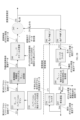
[0031]図2は、実施形態に従う系統図を示している。特に、図2Aは、最適化された再帰法によって拡張された高効率のCTに関して、先行推定物体密度261の投影276と共に、例示的な生の測定データ入力155と、変換200を使用する生の測定値からの投影空間密度データ201の計算と、変換投影データ206を取得するための変換205と、フィルタ285を使用する参照変換予測211とを示している。イノベーションゲイン調整220及び225は、図2Aと図2Bの間のブリッジを形成する。図2Bは、ボクセル密度推定データ261を取得するためのフィードバックセクションと共に、最適化された再帰法によって拡張された高効率のCTの例示的な前方処理及びスケーリングされた反転処理を示している。上の処理における一部の、ただし全部ではない変換は、Sunnegardh[15]における仮定とは対照的に、線形であってもよい。
[0031] Figure 2 illustrates a system diagram according to an embodiment. In particular, FIG. 2A shows an exemplary raw
[0032]一実施形態では、本明細書に記載された発明は、励起エネルギー120を観察対象の物体125に送信するための1つ又は複数の送信器115と、観察対象の物体125に送信された励起エネルギー120に応答して1つ又は複数の検出器145によって受信されたエネルギーをエンコードする投影空間データを生成するための1つ又は複数の検出器145と、1つ又は複数の送信器115を制御して励起エネルギー120を送信し、1つ又は複数の検出器145を制御して投影空間データ155を生成するためのコントローラ135と、投影空間データ155を受信し、例えば図2に示され、本明細書において説明されたプロセスによって、投影空間データ155を処理するために、少なくとも1つのプロセッサを含んでいる、画像再構成器165とを含んでもよい。
[0032] In one embodiment, the invention described herein provides one or
[0033]一部の実施形態に従って、画像再構成器165は、ボクセルのセットに対して投影値を計算することと、ピクセルのセットに対して投影値を計算することと、逆投影値を計算することと、他の情報源を使用して残りのピクセル及びボクセルを計算することと、特定の物体の先験的に知られた高密度のボクセル及び対応するピクセルの期待される投影範囲、又はボクセル及び対応する不足している投影測定値などの、ボクセルとピクセルの間の関数関係を使用するか、又は構築することとを実行してもよい。例えば、ミッシングウエッジ問題(L.Paavolainen他[16])又はスパース投影などにおいて、一部の投影値が不足している場合、Dempster 他[17]に記載されている期待値最大化(EM:expectation maximization)法を使用して予測を行って、(期待される)不足しているピクセル測定値を置き換えてもよい。
[0033] According to some embodiments,
[0034]EM法は、無限の観測ノイズに相当する不足しているデータのケースを表す。画像の一部の領域では、信頼性が低いと考えられるデータ(DRLR:Data regarded less reliable)は、無限の観測ノイズではなく、観測ノイズが増加しているデータとして同等に表されてもよい。EM法と共に、DRLRを含む利用可能なすべてのデータを使用して、それらの領域内のデータを非常に効率的に再計算/推定し、再計算/補正されたEMデータ(REMD:re-computed/corrected EM data)を生成することができる。その後、DRLR及びREMDの重み付きの組み合わせを、次のプロセスの反復の入力値として使用して、データの信頼性に依存するデータの重み付けの問題を解決することができる。相対的な重み付けは、例えば、結合されたノイズレベルに基づいてもよい。そのため、画像再構成器165は、少なくとも1つの信頼性が低いデータ又は不足している測定データの一部を、重み付き予測投影データ276を使用して、再計算又は補正してもよい。
[0034] The EM method represents the case of missing data corresponding to infinite observation noise. In some regions of the image, data considered less reliable (DRLR) may equivalently be represented as data with increasing observation noise rather than infinite observation noise. In conjunction with the EM method, all available data, including DRLR, are used to re-compute/estimate the data in those regions very efficiently, yielding re-computed/corrected EM data (REMD). /corrected EM data). The weighted combination of DRLR and REMD can then be used as input values for the next iteration of the process to solve data weighting problems that depend on data reliability. Relative weighting may be based on combined noise levels, for example. As such,
[0035]本発明の実施形態は、例えば、1つ又は複数のプロセッサを含んでいるワークステーションと、1つ又は複数のプロセッサによって実行されるソフトウェアを格納している1つ又は複数の非一時的データストレージデバイス180とを含んでもよく、このソフトウェアは、図2に示され、本明細書において説明されているプロセスを実施するためのソフトウェアコードを含んでもよい。
[0035] Embodiments of the present invention include, for example, a workstation containing one or more processors and one or more non-transitory workstations storing software executed by the one or more processors.
[0036]本発明の実施形態は、1つ又は複数のデータストレージデバイス180に格納されたソフトウェアコードを実行する1つ又は複数のプロセッサによって実施される方法を提供してもよく、この方法は、図2に示され、本明細書において説明されているプロセスを実施するためのステップを含んでいる。
[0036] Embodiments of the present invention may provide a method implemented by one or more processors executing software code stored in one or more
[0037]例えば、画像再構成器165は、投影空間データ155を変換して投影ピクセルデータ201を取得することと、投影ピクセルデータ201を非線形に変換して測定された変換ピクセルデータ206を取得することと、第1のピクセルイノベーション結果データ216を計算して、測定された変換ピクセルデータ206と予測変換ピクセルデータ211の間の差異を特徴付けることと、第1のピクセルイノベーション結果データ216をデータストレージデバイス180に記録することと、第2のピクセルイノベーション結果データ221を計算することであって、第1のピクセルイノベーション結果データ216が非線形変換205及び210の2つのセットの傾斜の反転に基づいて再スケーリングされる、ことと、第2のピクセルイノベーション結果データ221に基づいて、先行する反復から第3のピクセルイノベーション結果データ226を計算することと、断層撮影再構成アルゴリズムを使用して予備的変換物体密度更新データ236を取得して、第2のピクセルイノベーション結果データ221を近似的に反転することと、ボクセル密度の非線形変換290のセットから得られた傾き及び非線形逆変換250のセットの反転傾斜を使用して、予備的変換物体密度更新データ236を再スケーリングすることによって、変換物体ボクセル密度更新データ241を計算することと、変換物体ボクセル密度更新データ241を先行する反復からの先行するボクセルデータ推定値291と累算して変換物体ボクセル密度推定値246を形成することと、変換物体ボクセル密度推定値246を変換することによって、生のボクセル密度データ251を計算することと、ローパスフィルタを使用して生のボクセル密度データ251を平滑化して、予備的ボクセル密度推定データ256を取得することと、物体構造情報を使用して予備的ボクセル密度推定データ256を再推定することによって、ボクセル密度推定データ261を計算することと、ボクセル密度推定データ261をデータストレージデバイス180に格納することと、ボクセル密度推定データ261を単位遅延時間だけ遅らせて、前のボクセル密度推定データ266を取得することと、ローパスフィルタを使用して前のボクセル密度推定データ266を平滑化して、平滑化された前のボクセル密度推定データ271を取得することと、平滑化された前のボクセル密度推定データ271を変換して、先行するボクセルデータ推定値291を取得することと、断層撮影投影アルゴリズムを使用して、前のボクセル密度推定データ266から予測投影データ276を計算することと、ローパスフィルタ285を使用して予測投影データ276を平滑化して、平滑化された予測投影データ286を取得することと、平滑化された予測投影データ286を変換して予測変換ピクセルデータ211を取得することと、予測投影データ276と投影ピクセルデータ201を比較することによって、再構成済み画像誤差データ160を決定することと、再構成済み画像誤差データ160をデータストレージデバイス180に格納することとによって、投影空間データを処理してもよく、又はソフトウェアは、これらのことを実行するためのソフトウェアコードを含んでもよく、又は方法は、これらのことを実行するためのステップを含んでもよい。
[0037] For example,
[0038]本発明の実施形態の説明において、及び図2A及び図2Bにおいて、投影空間データ155は、「測定されたピクセルデータ155」、「物体画像化データ」、「生の測定データ入力155」、及び「入力データ155」とも呼ばれる。
[0038] In describing embodiments of the present invention, and in Figures 2A and 2B,
[0039]再構成済み画像誤差データ160は、「残差データ160」、「投影残差160」、「画像データの残差160」、「イノベーションの残差160」、「データ160」、及び「残差のセット160」とも呼ばれる。
[0039] The reconstructed
[0040]画像再構成器165は、本明細書では、「内側フィードバックループ165」及び「画像再構成コンピュータ」とも呼ばれる。
[0040]
[0041]ボックス200の変換を使用して投影方向に沿って累積物体ボクセル密度によって生成された投影ピクセルデータ201は、本明細書では、「投影積分物体密度201」、「投影空間密度データ201」、「入力信号データ201」、「近似的投影データ」、「入力データ201」、「投影201」、「データ201」、「投影データピクセルセットs(i)201」、及び「入力投影ピクセル」とも呼ばれる。
[0041] The projected
[0042]変換205は、本明細書では「入力変換関数」とも呼ばれる。複数の入力変換関数(又は1つの入力変換関数)205は、線形又は非線形であってもよい。
[0042]
[0043]測定された変換ピクセルデータ206は、本明細書では、「測定された変換ピクセル206」、「ピクセルデータ206」、「変換積分投影物体密度206」、「変換投影データ206」、「イノベーションデータ206」、及び「変換投影物体密度206」とも呼ばれる。
[0043] Measured transformed
[0044]変換210は、本明細書では「参照変換関数」とも呼ばれる。複数の参照変換関数(又は1つの参照変換関数)210は、線形又は非線形であってもよい。
[0044]
[0045]予測変換ピクセルデータ211は、本明細書では、「変換予測211」、「予測データ211」、「予測変換ピクセル211」、及び「変換予測データ211」とも呼ばれる。
[0045] Predictive transformed
[0046]第1のピクセルイノベーション結果データ216は、本明細書では、「再構成画像誤差データ216」、「画像誤差データ216」、「画像データの残差216」、「イノベーションの残差216」、「データ216」、「イノベーション216」、「イノベーションデータ216」、「残差データ216」、及び「残差216」とも呼ばれる。
[0046] The first pixel
[0047]第2のピクセルイノベーション結果データ221は、本明細書では、「誤差データ221」、「イノベーションデータ221」、「イノベーションの残差221」、及び「データ221」とも呼ばれる。
[0047] The second pixel
[0048]第3のピクセルイノベーション結果データ226は、本明細書では、「イノベーションの残差226」、「データ226」、及び「イノベーションデータ226」とも呼ばれる。
[0048] The third pixel
[0049]予備的ボクセル更新データ236は、本明細書では、「予備的変換物体密度更新データ236」、「予備的更新データ236」、及び「予備的変換物体更新データ」とも呼ばれる。
[0049] Preliminary
[0050]変換物体ボクセル密度更新データ241は、本明細書では「更新データ241」とも呼ばれる。
[0050] Transformed object voxel
[0051]変換物体ボクセル密度更新推定値246は、本明細書では、「変換密度推定値246」、「変換ボクセル密度推定値246」、及び「データ246」とも呼ばれる。
[0051] Transformed object voxel density update estimates 246 are also referred to herein as "transformed
[0052]生のボクセル密度データ251は、本明細書では「生のボクセル密度推定データ251」とも呼ばれる。 [0052] Raw voxel density data 251 is also referred to herein as "raw voxel density estimate data 251".
[0053]再構成済み画像データ261は、本明細書では、「データ261」、「推定物体密度261」、「ボクセル密度推定データ261」、「物体密度データ261」、「再構成済み物体261」、「物体データ261」、「物体空間画像」、及び「画像データ261」とも呼ばれる。
[0053]
[0054]既知の参照モデルと計算された物体密度261の間の不一致は、MMR-261と呼ばれる。
[0054] The discrepancy between the known reference model and the
[0055]投影276は、本明細書では、「予測投影データ276」、「予測空間データ276」、「予測投影空間ピクセル276」、「データ276」、及び「予測フィードバック測定ピクセル276」とも呼ばれる。
[0055]
[0056]平滑化された予測投影データ286は、本明細書では「データ286」と呼ばれてもよい。 [0056] The smoothed predicted projection data 286 may be referred to herein as "data 286."
[0057]図2A及び図2Bに示されている画像再構成器165における高い処理性能は、次の3つのステップのプロセスとして要約することができる。
[0057] The high processing performance in the
[0058]第1に、一部の処理ステップでデータ処理の線形化を使用し、線形反転断層撮影手法を効率的に使用して、理想的には物体に関連するすべての空間周波数成分を捕捉できるようにする、フィードバックループ内の投影ピクセルデータ201からボクセル密度推定データ261へのフィードフォワードデータの反転処理セクション。正のボクセル密度推定データ261を実現するために、小信号ボクセルゲイン係数、及び中間の変換物体ボクセル密度推定値246の計算を可能にする、非線形変換が含まれる。
[0058] First, some processing steps use linearization of data processing, effectively using linear inversion tomography techniques to ideally capture all spatial frequency components associated with the object. Inversion processing section of feedforward data from projected
[0059]第2に、正の物体ボクセル密度推定データ261を計算して正の予測投影データ276を生成する、フィードバックループのデータ投影セクション。送信器115から開始して、データ201までの、対応する物体画像化プロセスを近似することによって、再構成の品質を考慮する投影予測器の成分Hは、物体投影プロセスの近似を計算する。反復ごとの最適化は、高効率であり、数値的な山登り法ではなく、フィードバックループの理論的特性に基づいている。
Second, a data projection section of the feedback loop that computes positive object voxel
[0060]第3に、未知のシステムの特性をより良く近似するために、画像収集システムにおける不確実性を表す、ベクトルpに含まれているパラメータのセットが選択され、それらの不確実性の影響を補正するように調整されてもよい。例えば、期待される散乱又はビームハードニングの計算における不確実性は、最初は、投影物体密度を推定するための、測定されたX線強度の単純な対数変換によって考慮されず、補正されたベクトルパラメータpを計算することによって考慮され、調整されてもよい。ベクトルパラメータpは、本明細書では「パラメータベクトルp」とも呼ばれる。pの成分の調整は、例えば、測定データの前処理200において補正を適用して、特定の物体データに関してビームハードニングを考慮するように、対数変換の基数を変更し、200及び275を使用してX線散乱を考慮するように、予測信号強度データ値を変更する。性能の尺度が、外部から制御可能な固定されたパラメータ成分の固定されたセットに関して、第1のイノベーションプロセス216、投影残差160、又は画像再構成コンピュータの物体データの期待値のうちの少なくとも1つから得ることができる。
[0060] Third, in order to better approximate the properties of the unknown system, a set of parameters contained in the vector p representing the uncertainties in the image acquisition system is chosen and their uncertainties Adjustments may be made to compensate for the effects. For example, uncertainties in the calculation of expected scatter or beam hardening are initially not accounted for by a simple logarithmic transformation of the measured x-ray intensities to estimate the projection object density, and the corrected vector It may be taken into account and adjusted by calculating the parameter p . Vector parameter p is also referred to herein as “
[0061]同様に、例えば、ラジアル圧縮センシング(CS:compressed sensing)磁気共鳴画像法(MRI)では、定量的に不十分に表された、ケース固有の物理データ収集及び処理特性が含まれることがあり、ベクトルパラメータpにおいて補正が計算されることがある。この補正プロセスは、物体密度データ261を予測投影データ276まで進めるループのフィードバックセクションにおいて、発生することがある。このプロセスは、データ115の効果を繰り返し、物体画像化データ155をボックス200に転送して、近似的投影データ201を生成する。データ収集プロセスの表現及びループのフィードバックセクションにおけるベクトルp内の対応する未知のパラメータの調整は、ベクトルp内の未知のパラメータの効率的で正確な調整を可能にする。パラメータの変更の効果は、例えば一部分において、ボックス275の投影行列H内の係数で表されてもよい。
[0061] Similarly, for example, radial compressed sensing (CS) magnetic resonance imaging (MRI) can involve case-specific physical data acquisition and processing characteristics that are poorly represented quantitatively. Yes, and corrections may be computed in the vector parameter p . This correction process may occur in the feedback section of the loop that advances
[0062]画像再構成器165で、測定されたピクセルデータ155から予測データ211までのプロセスの反復と共に、増加するグリッド分解能及びベクトルパラメータp内の固定パラメータを使用して、FBPの再構成時間に近い画像データ261の再構成時間を実現できる。この速度によって、pに含まれているシステムパラメータの反復改良が実現可能になる。例えば、画像データの残差160又は216が、インベスティゲータ170に送信される。インベスティゲータ170は、例えば高効率のLevenberg-Marquardtプロセスで、例えば画像データの残差160、216の二乗和、及び利用可能な場合は、既知の物体と計算された物体データの間の誤差の最小化を使用して、p内のパラメータの補正値を計算することができる。Levenberg-Marquardt法は、通常、他の手法によって使用される最急降下法及び関連するアプローチのk倍以上の時間がかかる(kは、調整するべき未知の数値である)。p内の改良されたパラメータは、画像再構成器165に戻される。pに適用されるデータ処理のこの第2の層の反復は、物体データ261の大きな改善につながる。このプロセスの結果の例が、図4に示されている。
[0062] In
[0063]一実施形態では、図2は画像再構成器165の機能を含んでもよい。例えば、図1の測定されたピクセルデータ155は、図2に示されているように、入力として供給されてもよい。測定されたピクセルデータ155は、実験的取得110、シミュレーション185、又は以前の実験又はシミュレーション或いはその他のデータソースから記録された投影ピクセルデータを含んでいるデータストレージデバイス180から取得されてもよい。測定されたピクセルデータ155は、画像再構成器165に、直接、又はネットワーク(例えば、ローカルエリアネットワーク(LAN)、広域ネットワーク(WAN)、インターネットなど)を介してリモートから提供されてもよい。一実施形態では、画像再構成器165は、測定されたピクセルデータ155を処理して、再構成済み物体261を生成してもよい。ボックス200で、測定されたピクセルデータ155が処理されて、投影ピクセルデータ201を取得する。測定されたピクセルデータ155は、その後のデータ処理の近似の精度に対応できる変換によって処理される。例えば、X線画像化では、対応する物体密度投影の推定値の予備的近似として取得するために、光子強度が負の対数によって変換されてもよい。この処理は、例えば、ビームハードニング、散乱、又は画像記録システムの欠陥の影響に関して、投影密度の推定値を調整するパラメータベクトルpの成分で表された変換を改良し、275内でのこれらの改良を推定する必要性を減らすことをさらに含んでもよい。ラジアルスキャニング(RS:radial scanning)圧縮センシング(CS)MRIでは、ボックス200は、フーリエ変換又は主成分法を使用して、測定されたピクセルデータ155を物体密度投影の空間密度データの予備的近似に変換してもよく、ボックス200は、例えば、パラメータベクトルpで表された変換を改良し、幾何学的電磁界歪及び設計された励起及び応答の測定条件からの逸脱に関して調整することを、さらに含んでよい。ボックス200における変換プロセスの詳細は、近似的な物体密度の投影密度を取得するために使用される特定の物理的画像化プロセスを近似するように適応されてもよい。
[0063] In one embodiment, FIG. For example, measured
[0064]図2A及び図2Bに示されている画像再構成器165における処理を理解するための別の方法は、次のように要約することができる。少なくとも行列Z(ボックス220)又は行列L(ボックス240)が決定され、期待される状態データ276を使用して状態データ201を処理するために使用されてもよく(例えば、変換ピクセルイノベーション221を取得するために行列Z(ボックス220)を使用するか、又はボクセルの更新241を取得するために行列L(ボックス240)を使用する)、この処理は、期待される状態データ276、行列Z(ボックス220)を決定するためのf11(ボックス205)及びf12(ボックス210)の関数セット、並びに行列L(ボックス240)を決定するためのf21(ボックス290)及びg22(ボックス250)の関数セットに依存する。
[0064] Another way to understand the processing in the
[0065]ボックス205で、物体の内部構造をエンコードする情報を含んでいる投影ピクセルデータ201が、ピクセルデータ206に非線形(又は線形)に変換されてもよい。ボックス205で、要素f11(例えば、f11(s)=log(s)であり、すべてのピクセル値s>so>epsについて、ピクセルごとにそれぞれf11(so)>cminである)を使用する通常は非線形な入力変換行列が、ピクセルごとに使用され、変換領域内の1つ又は複数の測定された変換ピクセル値206を計算してもよい(例えば、f11は、例えばビームハードニングを表す、パラメータの関数であってもよい)。ボックス205で、データが密度領域から変換領域に変換される。別の実施形態では、ボックス205で、f11が、近似的に、入力データ201の分散安定化関数として計算されてもよい。例えば、ボックス205で、f11が、近似的に、PET測定から取得された入力信号データ201のポアソン分散安定化平方根関数であってもよい。別の例として、例えば測定ノイズが一定である場合、f11は、線形関数又は線形関数のセットであってもよい。
[0065] At
[0066]ボックス210で、非線形(又は線形)参照変換f12をピクセルごとに使用して、予測投影データ276が1つ又は複数の予測変換ピクセル211に変換されてもよい。例えば、非線形参照変換を使用する場合、f12は対数関数(例えば、f12=log(.))であってもよい。本明細書において使用されるとき、「ピクセル」は、ピクセルの位置又はピクセルの値のことを指してもよい。同様に、本明細書において使用されるとき、「ボクセル」は、ボクセルの位置又はボクセルの値のことを指してもよい。ボックス210で、データが密度領域から変換領域に変換される。非線形(又は線形)参照変換f12は、密度領域からの1つ又は複数の予測投影空間ピクセル276(又は、ボックス285でフィルタ(ローパスフィルタなど)によって平滑化される場合、平滑化された予測投影データ286)を使用して、変換領域内の1つ又は複数の予測変換ピクセル211を計算してもよい。例えば、ボックス285で、物体の投影276に対する2次元の平滑化特性は、例えば3次元においてフィルタ270を使用して同じ物体データを平滑化するときの投影の効果の近似である。この概念は、さらに高い次元の再構成にも適用される。言い換えると、投影及び平滑化の線形処理は交換可能である。予測投影空間ピクセル276は、前のボクセル密度推定データ266を使用して、予測器のH(ボックス275内)から取得されてよい。非線形(又は線形)参照変換f12は、f11のピクセルごとの近似になる傾向がある。ここで、例えば、堅牢(ロバストな推定処理を可能にするために、f11の要素が、データ201のアーチファクトに関する調整を必要とする場合、f11及びf12は異なってもよい。別の例として、f12は、線形関数又は線形関数のセットであってもよい。
[0066] At
[0067]ボックス215で、変換領域内のイノベーションデータ216が計算されてもよい。ボックス215の一実施形態では、1つ又は複数の測定された変換ピクセル206が、予測変換ピクセル211(平滑化された予測投影データ286から非線形に変換されたデータ)と比較されて、イノベーションデータ216に対応する差異を生成してもよい。言い換えると、ボックス215で、対応する測定された変換ピクセル206と予測変換ピクセル211の間の差異が計算されて、第1のピクセルイノベーション結果データ216を生成してもよい。第1のピクセルイノベーション結果データ216が、残差分析、及びシステムパラメータの最適化に使用され、最終的に最良の物体密度再構成を生み出すことができる。ボックス215で、対応するピクセル位置の、(対応するピクセル位置の近傍領域内の)関連付けられた密度領域のピクセル値のボックス205からの非線形入力変換f11の反転傾斜及びボックス210からの非線形参照変換f12の反転傾斜の、重み付きの組み合わせzのそれぞれが、個別に計算されてもよい。ノイズが多いか、又は不正確なデータ276、及び特にノイズが多いデータ201では、特定の密度領域のピクセル値に対応する傾きが、空間的な連続的に隣接する値を含んでもよく、ロバストな関数を使用した再評価を受けてもよい。
[0067] At
[0068]ボックス220で、第1のピクセルイノベーション結果データ216が、ピクセルごとのマッチング行列Zによってスケーリングされて、誤差データ221を生成してもよい。ピクセルごとのマッチング行列Zは、現在の投影空間データ及びそれらの変換の特性から計算されてもよい。ボックス220のスケーリングマッチング行列Zは、各zが、関連付けられたピクセル位置に対応するように、zのセットを編成することによって計算されてもよい。この計算は、対応する入力ピクセル値及び参照ピクセル値に関する非線形入力変換関数205の反転傾斜及び非線形参照変換関数210の反転傾斜を使用してもよい。行列Zの係数は、1つ又は複数の測定された変換ピクセル206のピクセル値でのピクセル変換関数f11及び予測変換ピクセル211のピクセル値でのf12の組み合わせられた反転傾斜の表現であってもよい。反転傾斜zの組み合わせは、ノイズがない場合には、最適に近い値z-optを生成する可能性が高いプロセスを使用し、ノイズがある場合には、z-optに近い近似値を生成する可能性が高くなるように、反転傾斜を組み合わせる。ボックス220で、第2のピクセルイノベーション結果221が、第1のピクセルイノベーション結果データ216と、ピクセルイノベーションスケーリング行列Zの対応する要素の、ピクセルごとの積を使用して計算されてよい。ピクセルごとのイノベーションスケーリング行列Zは、対応する非線形入力ピクセル密度変換関数205の反転傾斜及び対応する非線形参照ピクセル密度変換関数210の反転傾斜をピクセルごとに使用して計算されてもよい。非線形入力ピクセル密度変換関数205は、範囲が制限されるか、又はロバスト(例えば、制約された値)であってもよい。非線形参照ピクセル密度変換関数210は、範囲が制限されるか、又はロバスト(例えば、制約された値)であってもよい。
[0068] At
[0069]ボックス220で、ピクセルの連続的な特性に基づく米国特許第8,660,330号の手法と同等の行列ゲインの改良及び隣接する第1のピクセルイノベーション結果データ216が、任意選択的に統合されてもよい。
[0069] In
[0070]任意選択的なボックス225で、ピクセルの連続的な特性に基づく米国特許第8,660,330号の手法と同等の第2の直列なイノベーションゲイン行列G及び隣接するピクセルイノベーション結果が、第2のピクセルイノベーション結果データ221を第3のピクセルイノベーション結果データ226に変換してもよい。ボックス225で、ピクセルごとの補正ゲイン行列Gの要素が、第2のピクセルイノベーション結果データ221及び第3のピクセルイノベーション結果データ226内の対応するピクセルに関連付けられてもよい。第2のピクセルイノベーション結果データ221は、例えば、米国特許第8,660,330号のゲイン評価手法に対応する、第1のピクセルイノベーション結果データ216又は第2のピクセルイノベーション結果データ221の連続的な特性に基づくゲイン評価手法を使用して、第3のピクセルイノベーション結果データ226の計算に使用されてもよい。
[0070] In
[0071]ボックス230で、イノベーションプロセスのいずれかにおいて連続的な特性を使用して、米国特許第8,660,330号のゲイン評価手法に対応する生の補正ゲインが決定されてもよい。例えば、ボックス230で、重み付け関数を使用して、イノベーションゲインの1つ又は複数の空間的に隣接する係数又は先行する反復からのイノベーションゲインの1つ又は複数の連続的な係数に対する回帰によって、ピクセルごとの補正ゲイン行列225が計算される。補正ゲイン行列225は、測定及びモデルの欠陥を表す。回帰の前に、イノベーションプロセッサ230において、第1のピクセルイノベーション結果データ216又は第2のピクセルイノベーション結果データ221のうちの少なくとも1つを使用して、生の補正係数が計算され、イノベーションパターンA又はBを識別し、係数の対応する生の補正の増加又は生の補正の減少を伴って変動する。
[0071] At
[0072]ボックス235で、第3のピクセルイノベーション結果データ226が、断層撮影再構成アルゴリズムに提供され、予備的ボクセル更新データ236を取得してもよい。断層撮影再構成アルゴリズムは、例えば、線形再構成アルゴリズム(LRA:linear reconstruction algorithm)であってもよい。例えば、Zeng他[1]のDC/平均投影値を使用する断層撮影再構成反転アルゴリズムが使用されてもよい。別の例として、断層撮影再構成アルゴリズムは、逆投影法であってもよい。通常、システムパラメータのセットによって特徴付けられる、必要なDC/平均投影値と他の周波数成分の間の関係は、利用できる投影データの量及び方向に依存することがある。例えば、2つの(ノイズがない)直角投影の場合、本発明による再構成は、再構成のための投影のフィルタリングを必要としなくてもよい。
[0072] At
[0073]ボックス240で、予備的変換物体密度更新データ236が、ボクセルごとの更新スケーリング行列Lの要素を使用して再スケーリングされてもよく、各変換物体ボクセル密度更新データ241が行列Lの要素に関連付けられてもよい。ボクセルごとの更新スケーリング行列Lは、変換された物体データ及び正の制約変換物体ボクセルデータ変換の特性から計算されてもよい。行列Lの要素の値は、対応する変換ボクセル密度推定値246の、ボックス250のg22のボクセルごとの要素を使用して、ボクセルごとの逆変換の要素の反転傾斜から計算されてもよい。
[0073] At
[0074]ボックス245で、変換密度推定値246が、変換物体ボクセル密度更新データ241を対応する変換先行ボクセルデータ推定値291に加算することによって、計算されてもよい。変換密度推定値246は、インベスティゲータ170で後で使用するために、データストレージデバイス180に格納されてもよい。
[0074] At
[0075]ボックス250で、変換密度推定値246が、密度領域に逆変換され、生のボクセル密度推定データ251を取得してもよい。ボックス250で、データが変換領域から密度領域に変換される。変換密度推定値246が、行列要素g22を使用してボクセルごとに非線形に変換され、生のボクセル密度推定データ251を生成してもよい。一実施形態では、ボックス250で、行列要素g22は、行列g22の主要な部分に関して、f11又はf12行列要素の1つ又は複数の関数タイプの近似逆関数としての関数タイプであってもよく、g22の行列要素は、変換密度推定値246のデータ範囲の少なくとも1つの領域内の外部入力を満たす出力値を計算するために使用されてよい。ボックス250の関数は、本明細書では「正の制約関数」と呼ばれてもよい。
[0075] At
[0076]ボックス255で、生のボクセル密度推定データ251がフィルタリングされて、予備的ボクセル密度推定データ256を取得してもよい。ボックス255は、ローパスフィルタを使用して、生のボクセル密度推定データ251を平滑化してもよい。ボックス255は、生のボクセル密度推定データ251をフィルタリングして、予備的ボクセル密度推定データ256を正として出力してもよい。ボックス270及び285で、ローパスフィルタが、出力を正に維持する特性を共有してもよく、ボックス255の関数を置き換えてもよい。
[0076] At
[0077]ボックス260で、物体の予備的ボクセル密度推定データ256が、最初の反復では単一のボクセルに対して、その後の反復では多数のボクセルに対して動作するPによって後処理され、ボクセル密度推定データ261の特性に関する適切な先験的情報を使用して、密度値を改良してもよい。この手法は、単一のボクセルから開始することができ、最初に複数のボクセルを必要としない。予備的ボクセル密度推定データ256を後処理することによって、(a)等しい又は増加したグリッド分解能、又は(b)等しい又は増加した密度値の分解能のうちの1つ又は複数に基づいて、1つ又は複数のボクセルを作成してもよい。ボックス265で、ボクセル密度推定データ261が、前のボクセル密度推定データ266として記録され、表示され、ボックス270のフィルタへの入力として送信され、その後、ボックス290の変換f21に送信され、ボックス275の予測投影プロセッサHへの入力としても送信される。
[0077] In
[0078]ボックス270で、前のボクセル密度推定データ266がフィルタリングされて、平滑化された前のボクセル密度推定データ271を取得する。ボックス270のフィルタは、ローパスフィルタであってもよい。
[0078] At
[0079]ボックス290で、平滑化された前のボクセル密度推定データ271が、非線形参照変換ファミリーf21(例えば、f21=log(.))を使用して、先行するボクセルデータの推定データ291に変換されてもよい。ボックス290で、データが密度領域から変換領域に変換される。非線形参照変換ファミリーf21は、本明細書では、フィードバック関数290と呼ばれてもよく、ボックス290内のフィードバック関数のセットと呼ばれてもよい。
[0079] In
[0080]ボックス275で、前のボクセル密度推定データ266が処理され、通常は単一のスパース投影行列Hの表現を使用して、予測投影データ276を取得してもよい。行列Hは、元の物体密度値の画像化を、物体投影密度値として繰り返すように設計されてもよい。しかし、図1の画像化プロセスにおける不確実性が、行列Hにおける不確実性をもたらすことがあり、画像化プロセスについてより多くのことが学習されたときに調整するために、ベクトルパラメータpで表されてもよい。例えば、行列Hは、ベクトルpでパラメータ化された、パターン化されたボクセル外投影成分を使用して、特定のボクセルに関する散乱を表してもよい。しかし、実際の処理では、行列Hの明示的な使用が回避されてもよい。
[0080] At
[0081]ボックス275の一実施形態では、機能は、例えばZhang他[2]及びLong他[3]において説明されている機能に関連していてもよい。
[0081] In one embodiment of
[0082]さらに、行列Hで要約されているボックス275内の投影プロセスは、例えば、少なくとも1つのシステムパラメータ又は物体パラメータを表してもよい。システムパラメータは、例えば、焦点の形状、焦点のビーム出口の強度及び硬度並びに出口の形状特性、変化する管の供給電圧、ビームに依存するX線検出器の特性、又はX線散乱のうちの1つ又は複数であってもよい。物体パラメータは、例えば、物体の動きを表してもよい。これらのプロセスの不確実性(例えば、システムパラメータ及び/又は物体パラメータ)は、ベクトルパラメータpで要約されてもよい。画像再構成では、未知のボクセル値の数が、ベクトルp内の未知の係数の数をはるかに上回るため、p自体のほんのわずかの成分が推定の対象になってもよい、ということに注意する。まばらな測定の状況では、ボクセル密度に対して制約を設け、例えばボックス255又はボックス260を使用することによって、p及び物体のボクセルが推定の対象になってもよい。
[0082] Further, the projection process in
[0083]ボックス275で、断層撮影投影アルゴリズムが、H(p)のベクトルパラメータpと共に使用されてもよい。pを変更せずに、図2示されている処理ループが収束した後に、パラメータpが、性能基準に対して改善された解を見つけるように調整されてもよい。この性能基準は、例えば、イノベーションプロセス216の残差の最後のセット、残差のセット160、又は物体の計算された値と参照値の間の値の不一致に基づいてもよい。
[0083] At
[0084]ボックス210で、非線形変換f12が予測投影データ276に適用されて、変換予測データ211を取得してもよい。
[0084] At
[0085]ベクトルパラメータpは、データ216、221、226、又は160を、例えば重み付き二乗和の最小化に使用して、システムパラメータを、変化する投影条件に最適に適合させる。投影条件は、例えば、ボックス275での投影演算Hのパラメータ、ボックス260で要約された後処理法P、並びにボックス205での関数f11、ボックス210での関数f12、ボックス270での関数f21、及びボックス250での関数g22のパラメータで表される。
[0085] The vector parameter p uses the
[0086]データ246及び261は、外部のシステム変数及び目的を満たすように変更されてもよい。例えば、データ246及び261に含まれている一部の物体密度変数を先験的に知られた固定値にリセットすると、残りの物体密度変数及びシステムパラメータのより迅速な収束を支援することができる。
[0086]
[0087]ボックス275で、予測投影データ276が、1つ又は複数の物体空間のボクセルのセットに基づいて計算されてもよく、物体空間のボクセルのセットは、物体空間のボクセルのセットが投影空間に投影されるときにサイズが変化する、複数の分解能のグリッド(例えば、単一のグリッド点を含む)をカバーしてもよい。
[0087] In
[0088]ボックス275で、適切な(1つ又は複数の)ピクセルのセットに関するボクセルの投影値が計算される。残りの投影値は、必要な範囲について、他の情報源を使用して計算されてもよい。
[0088] In
[0089]ボックス280で、投影ピクセルデータ201及び予測投影データ276から残差データ160が生成されてもよい。残差データ160が測定法のノイズ(例えば、X線画像化の場合のホワイトノイズ)に近づき、説明できない投影物体密度の痕跡を(例えば、パラメータpの係数が適切に決定され、図2A及び図2Bで表されたループ内のデータの密度が十分の収束したため)無視できる場合、計算された残差データ160がインベスティゲータ170及び出力デバイス175に転送されてもよい。
[0090]ボックス225で、各イノベーションでの補正ゲイン行列が、1つ又は複数の生の隣接した先行するイノベーションゲインを重み付けする空間的な連続的重み付け関数を使用して計算されてもよく、それらのイノベーションゲインは、例えば米国特許第8,660,330号で使用されるループゲイン決定の特徴の少なくとも一部を使用する方法で計算される。図2の現在のフィードバックループへの米国特許第8,660,330号の特徴の実装は、イノベーション216又は221が連続して統計的に有意な同一の符号である場合に、ボックス230での生のゲイン係数を増やして、パターンAを作成し、イノベーションが連続して統計的に有意な交互の符号である場合に、ボックス230での生のゲイン係数を減らして、パターンBを作成する。このアプローチの異なるバージョンが可能である。より基本的なプロセスのバージョンは、特定のイノベーションパターンを有する生のゲイン係数の著しく不正な値から開始し、反復iごとに、有意な代替のパターンを検出するまで、ゲインを徐々に変更して、関連付けられたパターンの有意性を減らし、関連付けられた生のゲイン係数を前の値にリセットして、このプロセスを再び開始することである。ボックス230での先行するイノベーションプロセスを使用するボックス225でのゲイン調整又はその他の適切なメカニズムの選択肢は、システムノイズ、例えば密度領域の物体空間内のフィルタ効果、逆投影フィルタ特性の誤差、ロバストな影響関数の使用、単位DCループのフィードバックゲインの逸脱、及びその他のモデルの欠陥などから生じる、反復ループ計算内の準最適なゲイン決定の影響を減らすために提供される。例えば、第1の影響関数のセットを使用して改良された第1のピクセルイノベーション結果データ216(Sunnegardh[15]を比較する)、第2の影響関数のセットを使用して改良された第2のピクセルイノベーション結果データ221、及び第3の影響関数のセットによって改良された第3のピクセルイノベーション結果データ226に関して、イノベーションが、重み付け関数を使用して補正ゲイン行列の係数を計算してもよく、この重み付け関数は、測定及びモデルの欠陥を考慮するために、1つ又は複数の空間的に隣接するイノベーション行列の係数又は先行する反復からの1つ又は複数の連続的なイノベーション行列の係数に対する回帰によって計算されてもよい。1つ又は複数の連続的なイノベーション行列の係数は、イノベーションゲインの1つ又は複数の連続的な係数と呼ばれてもよい。
[0090] At
[0091]ボックス170で、対象の物体が、pを制御するインベスティゲータによって、図2のループ内のpのセットごとの最後の反復によって作成された160、216、221、又は226の重み付きの収束したイノベーションの残差を使用して、反復的に改良されてもよい。重み付きのイノベーションの残差の各セットが、図1に示され、図2A及び2Bで要約されている内側のフィードバックループ165内で、十分適切に収束した反復から取得される場合に、外側のループ内で計算されたパラメータpの摂動が、最適化に使用されてもよい。
[0091] In
[0092]外部から制御可能なパラメータpの成分が、初期推定値から、イノベーションの残差160、216、221、226、或いは例えば、シミュレーションにおける、又は参照物体の密度に対して物体密度推定値の収束を評価するときなどの、既知のシステムの参照モデルからの逸脱に関して、外部の目的又は最小コストとの最良の一致を形成する推定値に、徐々に変化してもよい。画像再構成コンピュータ[165]の外部にあるインベスティゲータコンピュータ[170]は、既知の参照物体と対応する計算された物体密度の間の差異を特徴付ける投影残差又は物体の残差のうちの少なくとも1つの特性を使用しながら、パラメータベクトルの制御可能な成分を、初期設定から、外部の目的に対して最低のコストを生成する設定に徐々に変更するよう機能してもよい。
[0092] The component of the externally controllable parameter p is calculated from the initial estimate to the
[0093]投影残差は、先験的なパラメータ或いは近傍領域を表すパラメータ及び/又は近傍領域を使用して得られるパラメータを使用した、物体のシミュレーション及び課題の記録によって詳しく調べられた、ロバストな推定影響関数を使用して、処理されてもよい。これらのパラメータは、例えば、局所的な入力測定値、システムの特性、予測値、又は先験的に期待される物体及び測定の特性のうちの1つ又は複数の関数であってもよい。 [0093] Projection residuals are robust, probed by object simulations and task recordings using a priori parameters or parameters representing and/or obtained using neighborhood regions. It may be processed using an estimated influence function. These parameters may be, for example, functions of one or more of local input measurements, system properties, predictions, or a priori expected object and measurement properties.
[0094]投影残差は、選択範囲上の残差の平滑化、選択範囲上の残差のスケーリング、又は選択範囲上の影響関数による重み付けのうちの少なくとも1つを使用して処理されてもよい。 [0094] The projection residuals may be processed using at least one of smoothing the residuals over the selection, scaling the residuals over the selection, or weighting the residuals over the selection with an influence function. good.
[0095]イノベーションデータ216、221、226、予備的更新データ236、及び更新データ241が、影響関数を使用して処理されてもよい。測定されたピクセルデータ155が、影響関数を使用して処理されてもよい。同様に、既知の物体密度再構成のシミュレーション中に、例えば、不一致の残差MMR-261が、影響関数を使用して処理されてもよい。
[0095]
[0096]図2A及び2Bのプロセスの実施形態は、例えば、線形再構成アルゴリズム(LRA)(例えば、フィルタ補正逆投影(FBP)又はその他の資格のある、線形であることが好ましい、再構成アルゴリズム)の能力を使用して、断層撮影の反転問題の固有値に効率的に対処する、最適化された再帰法によって拡張された高効率のコンピュータ断層撮影(eHECTOR:extended high efficiency computed tomography with optimized recursions)を含んでもよい。このために、LRAは、220、225、及び240でピクセルごとの小信号データのゲインを使用して線形化されてもよい、非線形構造に埋め込まれてもよい。例えば、FBPが、単一のステップで、良好だが不完全な物体密度推定値を生成するのと同様に、本明細書では、FBPが、変換推定問題の線形化モデルに対して再帰的に使用されてもよい。正味の効果は、図2のこの線形化ループが、推定誤差の幾何学的縮小を含む縮小傾向が大きいマッピングを表すということである。この収縮は、測定ノイズ又はモデルの誤差などの残差が、それ以上の反復によって解決できない不一致を引き起こす場合に、終了する。そのような不一致は、投影残差において発生することがあり、ベクトルパラメータpの再推定のための原動力になる。 [0096] Embodiments of the processes of Figures 2A and 2B may be implemented, for example, by a Linear Reconstruction Algorithm (LRA) (eg, Filtered Back Projection (FBP) or other qualified, preferably linear, reconstruction algorithm). ) to efficiently address the eigenvalues of the tomographic reversal problem. may include To this end, the LRA may be embedded in a non-linear structure that may be linearized using the gain of the small-signal data per pixel at 220, 225, and 240. FIG. For example, just as FBP produces good but imperfect object density estimates in a single step, here, FBP is used recursively for linearized models of transform estimation problems. may be The net effect is that this linearization loop of FIG. 2 represents a highly shrinking mapping involving geometric shrinking of the estimation error. This shrinkage ends when residuals such as measurement noise or model errors cause discrepancies that cannot be resolved by further iterations. Such discrepancies can arise in the projection residuals and are the driving force for re-estimation of the vector parameter p .
[0097]線形化されたeHECTORの場合、理想的には、線形カルマンフィルタが使用されてもよい。しかし、断層撮影再構成の場合、この最適なカルマンフィルタの決定は、最新の計算リソースの能力を超える。ボックス235のこのフィルタでは、最適なカルマンゲインを使用する代わりに、LRAが、現在のメモリレスのカルマンフィルタゲインを近似するために使用される。
[0097] For linearized eHECTOR, ideally a linear Kalman filter may be used. However, for tomographic reconstruction, this optimal Kalman filter determination is beyond the capabilities of state-of-the-art computational resources. In this filter in
[0098]最適なカルマンフィルタを使用して線形フィルタリングをモデル化するときに、一連のイノベーションが、ホワイトノイズプロセスを形成する。イノベーションプロセスの分散は、メッセージモデル及び観測ノイズのランダムな原動力/データから生じる(Sage他[4]の268ページを参照)。しかし、準最適なアプローチである、eHECTORの非線形ループ設定の場合、中程度の相関関係の連続的なイノベーションが生成される。そのため、eHECTORのループ構造は、最適な最小二乗アルゴリズム(例えば、最適なカルマンフィルタ)から、いくつかの方法で逸脱している。例えば、LRAは、最適なフィルタゲインの準最適な近似である。さらに、小信号データの線形化は、最適なフィルタの適用の場合にのみ近似になり、イノベーションプロセスはホワイトプロセスにならない。それでも、中程度の密度データ値の変化の場合、適切に選択されたLRA(現在のフィルタ補正逆投影断層撮影などで使用されるLRAなど)は、反復ごとに、縮小傾向が大きいマッピングを提供する。例えば、グリッド分解能が徐々に増加する場合、中程度の密度値の変化を期待することができ、数回の反復での非線形フィルタの収束が可能になる。反復の計算コストが、幾何学的合計において蓄積し、最後の反復が、例えば単一の逆投影又は反転のコスト成分に近い、支配的なコスト成分を決定する。 [0098] A series of innovations form the white noise process when modeling linear filtering using an optimal Kalman filter. The variance of the innovation process arises from the random dynamics/data of the message model and the observational noise (see page 268 of Sage et al. [4]). However, the non-linear loop setting of eHECTOR, which is a suboptimal approach, produces continuous innovations of moderate correlation. Therefore, eHECTOR's loop structure deviates from the optimal least-squares algorithm (eg, optimal Kalman filter) in several ways. For example, LRA is a sub-optimal approximation of the optimal filter gain. Moreover, the linearization of small-signal data becomes an approximation only in the case of optimal filter application, and the innovation process is not a white process. Nonetheless, for moderate density data value changes, a well-chosen LRA (such as that used in current filtered backprojection tomography, etc.) provides a mapping that tends to shrink more from iteration to iteration. . For example, if the grid resolution is gradually increased, moderate density value changes can be expected, allowing the nonlinear filter to converge in a few iterations. The computational cost of iterations accumulates in the geometric summation, with the final iteration determining the dominant cost component, which is close to, for example, the cost component of a single backprojection or inversion.
[0099]グリッド分解能が増加するときに、イノベーションプロセスでの空間的な高周波成分が、より顕著になることがある。X線断層撮影では、例えば、物体密度推定値の収束において、これらの空間的な高周波投影成分が、空間的測定のホワイトノイズに近いノイズを生成する。連続的にグリッド分解能が増加するときに、イノベーションの相関関係は中程度のままである。しかし、これら及び近似のその他の態様の場合、現在のループ設定は、断層撮影再構成の実用的且つ効率的な計算にとって十分であり、図2A及び2Bで詳細に示されて
いる画像再構成器165において使用される計算の基礎を形成する。
[0099] As the grid resolution increases, spatial high frequency components in the innovation process may become more pronounced. In X-ray tomography, for example, in the convergence of object density estimates, these spatial high-frequency projection components produce noise that approximates the white noise of spatial measurements. The correlation of innovation remains moderate when the grid resolution is continuously increased. However, for these and other aspects of approximation, the current loop settings are sufficient for practical and efficient computation of tomographic reconstructions and image reconstructors shown in detail in FIGS. It forms the basis of the calculations used in H.165.
[0100]本発明の一実施形態では、ボックス165での反復の連続的プロセス、ボックス255でのローパスデータフィルタの無視、小さいイノベーションを伴うグリッド分解能の増加、及び近似的で準最適な、明示的に計算されないLRAのゲインの使用が、状態変数の固定された次元数、明示的に計算されるゲインK、及び有限分散を含む適切に指定された前の統計値を使用する最適な線形カルマンフィルタと比較されてもよい。
[0100] In one embodiment of the invention, a continuous process of iteration at
[0101]これらのカルマンフィルタの条件のいずれも、図2の計算を正確に表さない。それでも、この計算モデルは、図2の反復プロセスの定性的評価を可能にする。 [0101] None of these Kalman filter conditions accurately represent the computation of FIG. Nevertheless, this computational model allows a qualitative evaluation of the iterative process of FIG.
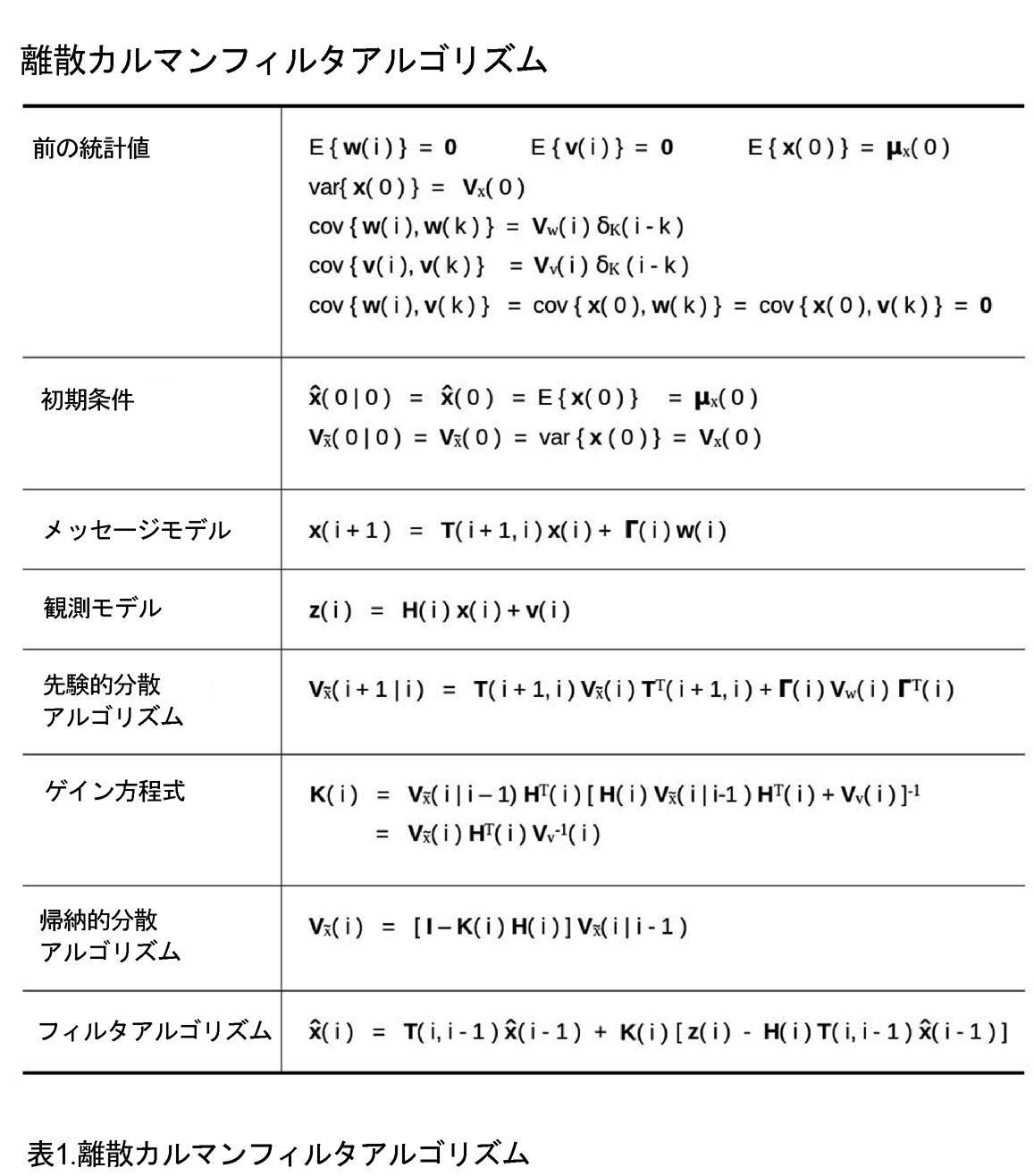
[0102]理想的な状況の場合に期待される性能の比較及び推定のために、表1に、Sage他[4]の268ページに示されている最適な離散カルマンフィルタアルゴリズムを編集して示している。
[0103]カルマンフィルタの比較の線形化部分は、次の方法でモデル化される。簡単にするために、ノイズ駆動型の動的システムの成分(表1)が存在しない静的システムについて考え、VW(i>0)=0とし、ただし初期分散VX(0)=VW(0)=VM≠0が、初期モデル状態共分散行列を表すとする。このモデルの状態xmの推定は、先行する状態の推定と、カルマンゲインK(i)によって重み付けされたイノベーションの組み合わせである(Sage他[4]の268ページを参照)。ここで、独立した測定ノイズの寄与の新しいセットではなく、測定成分の同じ固定されたセットを使用しているにもかかわらず、相関関係のない観測ノイズVV(i)が仮定される。連続的な相関関係は、ノイズデータが、その後、相互に一致しないことがあるため、例えば、平滑化処理、グリッド分解能の同様の増加、及び冗長な測定を考慮して、無視される。そのため、連続的な相関関係は、物体密度において(ほとんど)表すことができず(ただし、損傷を与える画像ノイズを除く)、したがって、状態の更新は、ホワイトノイズの存在における計算ステップと同じ計算ステップを使用してもよい。このモデルは、物体125が存在しないときのノイズ値の固定されたセットの再構成が、物体125の最終的な存在と比較したときに、無視できるボクセル密度を生成する程度まで、正当化することがでる。実際、ボックス255、260、270、及び285は、わずかなフィルタ効果を使用して、ボクセルデータ値における高周波成分を抑制し、それに応じて、例えば「物体投影の不一致」に起因する、大きい投影残差値をそのままにすることができる。最初は必ずしも最適でないカルマンフィルタモデルの線形化部分は、物体密度状態ベクトルxに関して、次のように表すことができる。
x(i)=x(i-1)+K(i)[z(i)-H(i)x(i-1)] [1.1]
K(i)=VX(i)HT(i)VV
-1(i) [1.2]
ここで、
VW(0)は、状態の分散VX(i)に含まれている初期物体密度の分散を表す [1.3]
z(i)=H(i)x(i)+v(i) 投影測定ベクトル [1.4]
ここで、
H(i) 物体密度状態ベクトルx(i)の観測行列 [1.5]
v(i)は、観測/測定ノイズである。 [1.6]
[0103] The linearization part of the Kalman filter comparison is modeled in the following way. For simplicity, consider a static system in which the noise-driven dynamic system components (Table 1) do not exist, let V w (i>0)=0, where the initial variance V x (0)=V w Let (0)=V M ≠0 denote the initial model state covariance matrix. The estimate of the state x m of this model is a combination of the preceding state estimate and the innovation weighted by the Kalman gain K(i) (see page 268 of Sage et al. [4]). Here an uncorrelated observation noise V V (i) is assumed, albeit using the same fixed set of measurement components rather than a new set of independent measurement noise contributions. Continuous correlations are ignored because the noise data may then not match each other, for example, considering smoothing processes, similar increases in grid resolution, and redundant measurements. As such, continuous correlations are (almost) unrepresentable in object density (except for damaging image noise), and state updates are therefore the same computational steps as in the presence of white noise. may be used. This model justifies to the extent that reconstruction of a fixed set of noise values when
x (i)= x (i-1)+K(i)[ z (i)-H(i) x (i-1)] [1.1]
K(i)= VX (i) HT (i) VV -1 (i) [1.2]
here,
V W (0) represents the variance of the initial object density contained in the state variance V X (i) [1.3]
z (i)=H(i) x (i)+ v (i) projection measurement vector [1.4]
here,
H(i) Observation matrix of object density state vector x (i) [1.5]
v (i) is the observation/measurement noise. [1.6]
[0104]システムノイズVW=0及び一定な相関関係のない観測ノイズVV(i)によって駆動されるメッセージ物体密度モデルの場合、iが無限大になるにつれて、カルマンゲインK(i)が0に収束する。
K(i)→0 [1.7]
観測ノイズの固定パターンを前提として、固定されたグリッド分解能での反復中に、対応するeHECTORにおいてデータ処理の線形化の動作点を決定している間は、次の式をそのままにすることで、十分であることがある。
K(i+1)=K(i) [1.8]
[0104] For a message object density model driven by system noise V W =0 and constant uncorrelated observation noise V V (i), the Kalman gain K(i) is 0 as i goes to infinity. converges to
K(i)→0 [1.7]
Given a fixed pattern of observation noise, while determining the operating point of the linearization of the data processing in the corresponding eHECTOR during iterations with a fixed grid resolution, leaving Sometimes enough.
K(i+1)=K(i) [1.8]
[0105]物体のボクセル数及び投影ピクセル数が大きいCTでは、数値的な理由のため、カルマンゲインフィルタシステム(特に、カルマンゲイン)は、計算不可能になる。しかし、同等の特性を有するLRAの近似を利用できる。最適なカルマンゲインに対するそのような近似は、Radon[5]の設定、Wood他[14]による小規模システムの最小分散の実装、又は最適なカルマンフィルタのような1ステップの反転を提供しないが、大規模システムの場合に、良好な縮小傾向のLRAが得られる。例えば、Radonのアプローチ[5]によって動機付けられた近似を使用して、FBPに類似する縮小傾向のマッピングが得られる(ただし、Zeng他[1]を参照)。 [0105] In CT with a large number of object voxels and projection pixels, the Kalman gain filter system (especially the Kalman gain) becomes uncomputable for numerical reasons. However, an approximation of LRA with comparable properties is available. Such an approximation to the optimal Kalman gain does not provide a one-step inversion like the setting of Radon [5], the minimal-variance implementation of small-scale systems by Wood et al. [14], or the optimal Kalman filter. For scale systems, a good shrinking LRA is obtained. For example, an approximation motivated by Radon's approach [5] is used to obtain a mapping of contraction trends similar to FBP (but see Zeng et al. [1]).
[0106]図2は、例えば、対数関数f11(ボックス205)、対数関数f12(ボックス210)、対数関数f21(ボックス290)、指数関数g22(ボックス250)、イノベーションスケーリング行列Z(ボックス220)、及び更新スケーリング行列L(ボックス240)を使用する特別な場合も示している。ボックス220及び240の場合、行列Z及びLはそれぞれ、対角優位行列によって表されてもよく、各対角要素は、データストリーム内の単一のピクセル又は単一のボクセルなどのデータ要素に対応する。図2Aのボックス220の反復iで、行列Z(i)の要素は、第1の成分である、投影データのピクセルセットs(i)201に関する関数f11(s(i))(ボックス205)の小信号の反転傾斜と、補完的な対応する重み付きの第2の成分である、関数f12(pf(i))(ボックス210)の小信号の反転傾斜との、ピクセルごとの加重平均を表してもよく、pf(i)は、予測フィードバック測定ピクセル276の値のセットであってもよい。ボックス240で、行列L(i)の要素は、関数g22(dtr(i))のボクセルごとの小信号の反転傾斜、又はその反転傾斜と、関数f21(266)の小信号の傾斜との加重平均を表してもよい。
[0106] FIG. 2 illustrates, for example, logarithmic function f 11 (box 205), logarithmic function f 12 (box 210), logarithmic function f 21 (box 290), exponential function g 22 (box 250), innovation scaling matrix Z ( box 220), and the special case of using an updated scaling matrix L (box 240). For
[0107]関数f11(ボックス205)及び関数f12(ボックス210)は、同一のセットの対を形成してもよく、関数f21(ボックス290)及び関数g22(ボックス250)は、相互に逆関数であるセットの対を形成してもよい。目的に応じて、関数f11(ボックス205)、f12(ボックス210)、及びf21(ボックス290)の機能は、例えば、対数関数(例えば、投影がごく少数である場合)又は平方根関数(例えば、測定された陽電子放射断層撮影(PET)又は単光子断層撮影(SPECT)の光子計数信号の分散安定化の場合)であってもよい。関数g22(ボックス250)は、例えば、指数関数又は二次関数の一部であってもよい。関数f11(ボックス205)及び関数f12(ボックス210)は、例えば、1つ又は複数の入力投影ピクセルのポアソン分散安定化平方根関数であってもよい。 [0107] Function f 11 (box 205) and function f 12 (box 210) may form the same set of pairs, and function f 21 (box 290) and function g 22 (box 250) are mutually may form pairs of sets that are inverse functions of . Depending on the purpose, functions of functions f 11 (box 205), f 12 (box 210), and f 21 (box 290) can be, for example, logarithmic functions (for example, if projections are very few) or square root functions ( For example, for dispersion stabilization of the measured positron emission tomography (PET) or single photon emission tomography (SPECT) photon counting signal). Function g 22 (box 250) may be part of an exponential or quadratic function, for example. Function f 11 (box 205) and function f 12 (box 210) may be, for example, Poisson variance-stabilized square root functions of one or more input projection pixels.
[0108]CT再構成のための近似的なカルマンフィルタゲイン行列Gを得る、米国特許第8,660,330号の概念の代替及び拡張が使用されてもよい。そのため、図2では、制約を可能にするように設計された、一般化された非線形の近似的カルマンフィルタが要約されている。強化の態様は、ボックス235での、現在の非線形フレームワーク内で近似的なカルマンフィルタゲインをエミュレートするための、近似的な逆投影又はその他の反転アルゴリズムの埋め込みである。これらの機能的及び構造的変更は、1ステップの最適な推定器を損なうが、ボクセル密度推定フィルタ内で線形化を使用して、急速に収束する断層撮影再構成を可能にする。一般化では、図2に示されているf11(ボックス205)及びf12(ボックス210)、並びにf21(ボックス270)及びg22(ボックス250)の非線形関数の選択に関連する、行列Z(ボックス220)及びL(ボックス240)を追加する。
[0108] Alternatives and extensions of the concept of US Pat. No. 8,660,330 to obtain an approximate Kalman filter gain matrix G for CT reconstruction may be used. As such, FIG. 2 summarizes a generalized nonlinear approximate Kalman filter designed to enable constraints. An enhancement aspect is the embedding of approximate backprojection or other inversion algorithms in
[0109]表1から、図2に示されている静的線形モデルに関して、次の式が得られる。
T(i+1,i)=I [2.1]
Γ(i)=I i=0の場合 [2.2]
=0 i>0の場合
[0109] From Table 1, for the static linear model shown in FIG.
T(i+1,i)=I[2.1]
When Γ(i)=I i=0 [2.2]
=0 if i>0
[0110]前の統計値E[x(0)]=μは、インプラントのような、先験的に知られた密度値μ xiを含む領域などの、ベクトルyで表されたxの固定されたサブセクションを含んでもよい。これに対応して、Vyy(i)=0である。それに応じて、反復内でyがμ eにリセットされ、μ eはg22 -1を使用して変換されたμ xiのサブセットを表す。 [0110] The previous statistic E[ x (0)] = μ is the fixed value of x represented by the vector y , such as the area containing the a priori known density value μ xi , such as the implant. may contain additional subsections. Correspondingly, V yy (i)=0. Accordingly, y is reset to μ e within the iteration, where μ e represents the subset of μ xi transformed using g 22 −1 .
[0111]効果的な線形画像再構成(LRA)は、ルートが通常は<<1(及び、det||CX||<<1)である、縮小するマッピングCXを生成する。
VX(i)=CXVX(i|i-1)=CXVX(i-1) [2.3]
帰納的分散アルゴリズムから、次式が得られる。
K(i)H(i)=I-CX(i)又はCX(i)=I-K(i)H(i) [2.4]
[0111] Efficient linear image reconstruction (LRA) produces a declining mapping Cx whose root is usually <<1 (and det|| Cx ||<<1).
VX (i)= CXVX (i|i-1)= CXVX (i-1) [ 2.3 ]
From the recursive variance algorithm, we get:
K(i)H(i)= ICX (i) or CX (i)=IK(i)H(i) [2.4]
[0112]小信号表現の場合、新しいカルマンゲインK’が指定され、小信号ループゲイン行列Z(ボックス220)及びL(ボックス240)に関連付けられてもよい。小信号ループゲイン行列Z及びLは、非線形変換の傾斜に基づいてもよい。例えば、ゲイン行列Z(ボックス220)は、ボックス205(ボックス205では、投影ピクセルデータ201が入力され、例えば対数的に変換される)の入力変換の動作点及びボックス210の予測データ211に関連付けられた関数f11及びf12の傾斜を補償するために使用されてもよい。同様に、例えば、ゲイン行列L(ボックス240)は、出力変換g22(例えば、指数関数)及びその反転f21に関連付けられてもよい。線形の場合、カルマンK行列(ボックス235)は、例えば、フィルタ補正逆投影(FBP)又は逆投影フィルタ(BPF:back-projection filter)近似(Zeng他[1]を参照)などの、LRAによって近似されてもよく、Hは、散乱などの現象を含む、推定された物体の順投影であってもよい。
[0112] For the small-signal representation, a new Kalman gain K' may be specified and associated with the small-signal loop gain matrices Z (box 220) and L (box 240). The small signal loop gain matrices Z and L may be based on the slope of the nonlinear transform. For example, the gain matrix Z (box 220) is associated with the operating point of the input transform in box 205 (in which the projected
[0113]任意選択的なゲイン行列G(ボックス225)は、Kが通常、近似されるため、K(ボックス235)に対する補正を支援してもよく、G(ボックス225)は、エントロピー増加、安定化、及び制約するローパスフィルタ、先験的な制約、及びフィードバックループ内のその他の介入などの影響を補償するのを支援する。ローパスフィルタ255及び先験的な物体に関する知識260が、特にまばらな投影データの物体密度計算において、eHECTORの安定性を支援するように、設定されてもよい。
[0113] An optional gain matrix G (box 225) may help correct for K (box 235), since K is typically approximated, and G (box 225) increases entropy, stabilizes and to compensate for effects such as constraining low-pass filters, a priori constraints, and other interventions in the feedback loop. A low-
[0114]すべての行列について、退化した単一のグリッド点のケースに対して、小信号解析が、特定の入力データ201から開始し、例えば、スカラーゲイン(行列)Gを調整して、ユニティ(DC)ループゲインを提供してもよい。さらに多くのグリッド点が使用される場合、初期ループゲインは、例えば、米国特許第8,660,330号又はその他の基準に類似する観測されたイノベーションシーケンスデータに基づいて、行列Gを使用して調整されてもよい。フィードバックループの解析の一部の実施形態では(例えば、特定のグリッド分解能での物体再構成問題が、少数の投影を使用する場合などの、まばらな測定データセットを使用するのではない場合)、ボックス255での平滑化処理(エントロピー増加処理)の使用が無視されるか、又は影響を最小限に抑えるように調整されてもよい。
[0114] For all matrices, for the degenerate single grid point case, the small-signal analysis starts with a
[0115]ノイズが少なく、少量のイノベーションデータ206の場合、図2の非線形フィルタリング問題は、例えば表1に示されているカルマンフィルタ方程式を使用して解析されてもよい。
[0115] For low noise and small amounts of
[0116]簡単にするために、201のピクセルデータsが、中程度のノイズ及び実際の物体密度に近い計算された物体密度の収束に対応する、276の予測ピクセル値pに近い値を含んでいると仮定する。その場合、例えば、データ201の関数f11のピクセルごとの傾斜値及びデータ276の関数f12のピクセルごとの傾斜値は、おおよそ同じ(s≒p)である。276のフィードバックの摂動Δp(又は、同様に201の測定データの摂動Δs)の小信号ループゲイン特性を補償するために、小信号対角ゲイン行列Z(ボックス220)が、次の反転傾斜要素を含んでもよい(s≒pを仮定する)。
zdd=σpd/σf11(pd)=zd [2.5]
ここで、zdは、インデックスdでのZ行列の対角非ゼロ要素を表し、σは微分演算子である。傾斜zdは、データ201及び286のノイズ特性に応じて関数f12及び関数f11から得られた重み付きの組み合わせであってもよい。係数zdの使用は、下でさらに説明される影響関数による制約を受けることがある。
[0116] For simplicity, the pixel data s of 201 contain values close to the predicted pixel values p of 276, corresponding to moderate noise and convergence of the calculated object density close to the actual object density. Assume there is Then, for example, the pixel-by-pixel slope values of function f 11 in
z dd =σp d /σf 11 (p d )=z d [2.5]
where zd represents the diagonal nonzero elements of the Z matrix at index d and σ is the differential operator. The slope z d may be a weighted combination obtained from functions f 12 and f 11 depending on the noise characteristics of
[0117]その後、近似された小信号の摂動がLRA(ボックス235)を通過し、カルマンフィルタゲインを近似し、予備的ボクセル更新を計算してもよい。 [0117] The approximated small-signal perturbation may then be passed through an LRA (box 235) to approximate the Kalman filter gains and compute preliminary voxel updates.
[0118]フィルタの小信号出力(表1のx(i)に対応するデータ)の後に、小信号変換行列L(ボックス240)が続き、変換物体密度推定値dtr(i)のその後の非線形ゲインを補償してもよい。 [0118] The small-signal output of the filter (data corresponding to x(i) in Table 1) is followed by the small-signal transformation matrix L (box 240), the subsequent nonlinear gain of the transformed object density estimate dtr(i) may be compensated.
[0119]対角行列L(ボックス240、ボクセル密度Vqに関連する)は、次の要素を含む。
lqq=σvq/σg22(vq)lq [2.6]
インデックスqqをqに置き換えると、対角要素を示す。係数lqの使用は、下でさらに説明される影響関数による制約を受けることがある。
[0119] The diagonal matrix L (
lqq = σvq / σg22 (vq) lq [2.6]
Replacing the index qq with q indicates the diagonal element. Use of the coefficients l q may be constrained by influence functions further described below.
[0120]成分220、235、及び240を組み合わせるが、
(i)簡単にするために、G=Iのままにし、
(ii)dim(z)≧dim(x)であると仮定し、zは冗長であるが、物体密度xを計算するために独立して収集された測定値であるとすると、
新しい小信号の、入力データ201に依存する、カルマンフィルタに似たゲイン行列K’が得られる(dim(z)<dim(x)の場合に使用されるループ内の平滑化処理/エントロピー増加255及び260の処理を無視する)。
K’=LKZ [2.7]
[0120] Combining
(i) for simplicity, let G=I;
(ii) Assuming dim(z)≧dim(x), where z is a redundant but independently collected measurement for calculating the object density x,
A new small-signal Kalman filter-like gain matrix K′ is obtained that depends on the input data 201 (in-loop smoothing/
K′=LKZ [2.7]
[0121]関数g22(ボックス250)の成分の項の非線形の寄与の小信号近似(傾斜)から、再び、行列L-1が得られる。この簡略化されたモデルにおいてボックス255及び260を無視して、投影行列H(ボックス275)が、pd(i)≒sd(i)の範囲内の動作点で、f11[sd(i)](ボックス205)とf12[pd(i)](ボックス210)の重み付きの組み合わせによって形成された線形近似によって変更され、例えば、1/pd≒1/sdとなる傾斜要素の重み付きの組み合わせを使用するf11及びf12での対数変換の場合に、対角行列Z-1を生成する。したがって、L-1でのg22の小信号の置換及びf12とf11の組み合わせがZ-1をもたらし、新しい小信号データ摂動投影行列H’が得られ、次式で定義される。
H’=Z-1HL-1 [2.8]
[0121] A small-signal approximation (slope) of the nonlinear contribution of the component terms of the function g 22 (box 250) again yields the matrix L −1 . Ignoring
H′=Z −1 HL −1 [2.8]
[0122]新しいカルマンゲインK’と観測行列H’の共有の特性を確認すると、対角(スケーリング)行列L及びZを使用して、帰納的アルゴリズムから、次のループゲインが得られる。
K’H’=LKZZ-1HL-1=LKHL-1=L(I-CX)L-1=(I-LCXL-1) [2.9]
ここで、det||L||det||L-1||=1、CXのルート<<1であり、適切なLRAの使用を仮定する。小信号近似の場合に、フィードバックループを再帰的に通過することによって、最適なカルマンフィルタゲインに対するLRAの近似の逸脱CXによって制限される幾何学的物体密度縮小係数が得られる。例えば、IとKHの間の一致に応じて後の分散の削減を示す、表1の線形カルマンフィルタの帰納的分散アルゴリズムを比較する。反対に、一致しない測定成分は、それ以上縮小傾向があるマッピングがない、加重最小二乗推定につながる。収束での残差の構造は、診断システムの性能に役立つ。例えば、ホワイトノイズの投影残差及び投影残差において無視できる物体の特徴(もしあれば)は、収束を示し、再構成において取得されるモデルの精度を定量化することがある。
[0122] Observing the shared property of the new Kalman gain K' and the observation matrix H', using the diagonal (scaling) matrices L and Z, the following loop gains are obtained from the recursive algorithm.
K′H′=LKZZ −1 HL −1 =LKHL −1 =L(IC X )L −1 =(I−LC XL −1 ) [2.9]
Now assume that det||L||det||L −1 ||=1, the root of C X <<1, and the use of appropriate LRAs. For the small-signal approximation, a recursive pass through the feedback loop yields a geometric object density reduction factor bounded by the deviation CX of the LRA approximation to the optimal Kalman filter gain. For example, compare the linear Kalman filter recursive variance algorithm in Table 1, which shows the reduction of the posterior variance depending on the match between I and KH. Conversely, inconsistent measured components lead to weighted least-squares estimates with no further shrinking mappings. The structure of residuals at convergence helps the performance of the diagnostic system. For example, projection residuals of white noise and negligible object features (if any) in the projection residuals may indicate convergence and quantify the accuracy of the model obtained in reconstruction.
[0123]K(i)(方程式2.9)の有効性を表すCX(i)に対する判断は、次に基づいてもよい。
(i)一連の反復における物体の特徴の残差の縮小、
(ii)測定によって引き起こされる投影の背景ノイズの存在(例えば、X線断層撮影又は電子線断層撮影の場合の近似的な投影のホワイトノイズ)、物体の投影の特徴の不在(例えば、同じ物体の異なる測定のセットの残差間の差異を調べることによる)、及び
(iii)グリッド分解能の増加でイノベーションを比較するときの、連続的なホワイトイノベーションデータ216に近いデータの存在(216のより高い分解能でのピクセルに対応するように補間する必要があるより低いグリッド分解能からの遡及的なイノベーションステップ)。
[0123] A judgment on Cx (i), which represents the effectiveness of K(i) (equation 2.9), may be based on the following.
(i) reduction of residuals of object features in a series of iterations;
(ii) the presence of background noise in the projection caused by the measurement (e.g. white noise in approximate projections in the case of X-ray tomography or electron tomography), the absence of projection features of the object (e.g. and (iii) the presence of data close to continuous
[0124]LRAのK(ボックス235)の不正確さ(例えば、det||CX||≠0)及び出力変換(ボックス250)後のローパス平滑化/エントロピー増加処理(ボックス255)をそれぞれ補償するために、Kは、イノベーションゲイン調整行列G(ボックス225)を使用して増大されてもよい。ゲイン調整器G(ボックス225)は、入力データのf11の傾斜(ボックス205)及び観測の予測データのf12の傾斜(ボックス210)の動作点の範囲内で、ゲイン値を適度に変更する。ゲイン調整行列Gは、予測投影密度の一貫した過小推定又は過大推定から生じる、ビームハードニングなどの要因による影響を受けることがある。それらのビームハードニングの影響の補正に固有の方法が、他者によって開発されている。行列Lを使用する価値は、単位行列I(方程式2.9)の216~211の小信号ループゲイン全体を支援する関数g22に関連付けられた小信号ループゲインを補償することであり、それらの差異はボックス215において生じ、ノイズ以外の小さい差異を意味し、したがって、反復計算中の物体密度の急速な収束を意味する。
[0124] Compensate for LRA K (box 235) inaccuracy (e.g., det||C X ||≠0) and low-pass smoothing/entropy enhancement processing (box 255) after output transformation (box 250), respectively. To do so, K may be augmented using the innovation gain adjustment matrix G (box 225). A gain adjuster G (box 225) modifies the gain value moderately within the operating points of the f 11 slope of the input data (box 205) and the f 12 slope of the observed prediction data (box 210). . The gain adjustment matrix G may be affected by factors such as beam hardening resulting from consistent underestimation or overestimation of the projected projection density. Others have developed specific methods for correcting for these beam hardening effects. The value of using the matrix L is to compensate for the small signal loop gains associated with the function g 22 supporting the overall small signal loop gains 216-211 of the identity matrix I (equation 2.9), whose A difference occurs in
[0125]主に関数f11(ボックス205)、関数f12(ボックス210)、関数f21(ボックス290)、及び関数g22(ボックス250)の小信号の特性が、ボックス220の行列Z及びボックス240の行列Lに使用されてもよく、小信号行列要素の一部が、0に設定されるか、又は何らかの先験的な情報の存在下で除外されてもよい。例えば、インプラント又は患者の周囲の密度などの物体密度は、ある時点で先験的に知られてもよい。それらの物体密度の推定に関連付けられた要素は、除外されてもよく、対応する物体密度データが、既知のデータ値に置き換えられる。
[0125] Mainly the small-signal characteristics of function f11 (box 205), function f12 (box 210), function f21 (box 290), and function g22 (box 250) are the matrix Z in
[0126]断層撮影再構成の場合、既知ではなく、例えば、インプラントなどの物体の特性、ビームのスペクトル特性、放出されるビームの変化する硬度、物体の動き、散乱、呼吸及び心臓の動き、並びに画像再構成器165の外部のその他のシステムの構成要素に起因する、ビームハードニングにおける不確実性を表す他の手段によって観測もされないパラメータは、画像再構成器165内で、例えば図2に示されている投影行列H(ボックス275)で表されて、調整されてもよい。そのようなパラメータは、ボックス200、205、210、250、255、260、及び290の関数を調整してもよい。それらのパラメータは、例えばLevenberg-Marquardt(LM)のアプローチを使用して、一緒に推定されるか、又は別々に推定されてもよい。測定値のセットを記録した後に、LM又は同等のアプローチは残差データから計算し、それらの残差データは、対応する物体の推定が収束したときに、画像再構成器165内で変更されたパラメータのセットから計算されており、不確実性を含むパラメータに対する調整が、収束するまで継続する。
[0126] In the case of tomographic reconstruction, the unknown, e.g., properties of objects such as implants, spectral properties of the beam, varying hardness of the emitted beam, object motion, scattering, respiration and heart motion, and Parameters not observed by other means representing uncertainties in beam hardening due to other system components external to the
[0127]冠動脈枝の拍動モデルの推定にLM処理を使用する、そのようなLMベースの再構成の例が、図3及び図4に示されており、データは、医療用2方向Cアームシステムを使用して収集されている。モデルパラメータ計算では、50個以上のパラメータを使用して、例えばイメージインテンシファイアの静磁場及び変動磁場のゆがみ並びにCアームの位置の誤差から生じる投影の位置合わせを再推定した。 [0127] An example of such an LM-based reconstruction using LM processing for estimating the pulsatile model of the coronary artery branches is shown in Figures 3 and 4, where the data was obtained from a medical two-way C-arm collected using the system. In the model parameter calculations, more than 50 parameters were used to re-estimate projection alignment resulting from, for example, static and varying magnetic field distortions of the image intensifier and errors in the C-arm position.
[0128]画像再構成器165における反復の初期化は、多数のボクセルではなく、例えば投影ごとに単一のボクセル及び単一のピクセルから、低いグリッド分解能で開始してもよい。初期ボクセル密度は、例えば、投影密度の平均から得られる。次に、反復で、グリッド分解能が望ましいレベルに増やされてもよい。分解能の変化は、同じ反復間隔で行われなくてもよく、1回の分解能の増加量が同じでなくてもよい。グリッド分解能が増やされるときにモデルパラメータpの成分を組み込む数及び順序は、誤差の削減、又は例えばSchwarz[6]及びAkaike[7]などにおける情報基準に基づいて、事前に決定されてもよい。パラメータ係数の受容は、例えば、データ206又は160の測定値、及び再構成でpの成分を組み込むときの改善の程度に基づいてもよく、パラメータ及びそれらの選択の重要度の決定に使用されてもよい。
[0128] Iteration initialization in the
[0129]初期化後に、ボックス220及びボックス240によって、ループゲインの主要なゲイン調整が決定される。残りのゲイン調整があれば、それらのゲイン調整が、一連の先行するイノベーション216のパターンから得ることができる行列G(i)(ボックス225)のゲインを使用して実施されてもよい。固定されたグリッド分解能での有意な振動は、過剰なゲイン、持続する有意な静的イノベーション値の不十分なゲイン、及びランダムなパターンの適切なゲインを示していることがある(例えば、米国特許第8,660,330号を参照)。
[0129] After initialization,
[0130]発明の手法の比較 [0130] Comparison of Inventive Techniques
[0131]非線形の反復断層撮影再構成は、多くの人によって、長年にわたって集中的に追及されてきた。例えば、Elbakri他[8]及び[9]には、多エネルギーX線源スペクトル、エネルギー依存の減衰、及び重複しない材料を考慮するアプローチが記載されている。それらの目的は、既知のエネルギー依存の質量減衰係数を使用して未知の物体密度を計算することである。Elbakriのアプローチは、この多エネルギーモデルに対してペナルティ付き尤度関数を定式化し、順序付けられたサブセットの反復アルゴリズムを使用して、ボクセルごとに未知の物体密度を推定する。 [0131] Nonlinear iterative tomographic reconstruction has been intensively pursued by many over the years. For example, Elbakri et al. [8] and [9] describe an approach that considers multi-energy X-ray source spectra, energy-dependent attenuation, and non-overlapping materials. Their purpose is to calculate unknown object densities using known energy-dependent mass attenuation coefficients. Elbakri's approach formulates a penalized likelihood function for this multi-energy model and uses an ordered subset iterative algorithm to estimate the unknown object density for each voxel.
[0132]同様の目的に対処する多エネルギーの同時代数的再構成法(SART:Simultaneous Algebraic Reconstruction Technique)(アルゴリズム)のHumphriesの解析[10]は、収束条件が減衰係数の特性を含む複数の要因に依存することを示している。さらに、SARTの収束は保証されず、反復のヤコビ行列のスペクトル半径は、必ずしも1未満にならない。 [0132] Humphries' analysis of the multi-energy Simultaneous Algebraic Reconstruction Technique (SART) (algorithm) [10], which addresses similar objectives, states that the convergence criteria are multifactorial, including the properties of the damping coefficients. indicates that it depends on Furthermore, convergence of SART is not guaranteed, and the spectral radius of the Jacobian matrix of iterations is not necessarily less than one.
[0133]米国特許第8,923,583号は、安定化ペナルティ関数S(x)を使用してモデルの尤度D(y;x)を最小化することによって、マルチスペクトル測定からの二重エネルギーCTデータを再構成した。米国特許第8,923,583号には、測定値yから物体xを再構成するときに、「この方法の欠点は、xとyの間の非線形関係に起因して、関数D(y;x)をモデル化するのが、通常は非常に複雑であり、計算的に困難であることである」と記載されている。 [0133] U.S. Patent No. 8,923,583 uses a stabilizing penalty function S( x ) to minimize the model likelihood D( y ; Energy CT data were reconstructed. U.S. Pat. No. 8,923,583 states that when reconstructing an object x from measurements y , "a drawback of this method is that due to the non-linear relationship between x and y , the function D( y ; x ) is usually very complex and computationally difficult to model."
[0134]最近、Staub他[11]は、少数の固有ベクトル表現を物体の再構成に使用して、患者の生体構造の動きをボクセルごとのスケールで使用して追跡する能力を示した。Staub他[11]は、Nelder-Meadシンプレックスアルゴリズムが、物体の動きを表す少数のパラメータを推定するための最もロバストなアプローチであることを発見した。 [0134] Recently, Staub et al. [11] demonstrated the ability to use a small number of eigenvector representations for object reconstruction to track the motion of a patient's anatomy using a voxel-by-voxel scale. Staub et al. [11] found the Nelder-Mead simplex algorithm to be the most robust approach for estimating a small number of parameters describing object motion.
[0135]前述した困難を克服する革新的な代替の計算の概要説明を簡単にするために、新しいアプローチのすべてのモデルパラメータを推定の対象にすることができる。ビームハードニング、X線源スペクトルの変化、機器の動き又はずれなどを特徴付ける外部機器の特性のパラメータ、或いは物体の材料特性、物体の動きなどの物体内部のパラメータが、単一のパラメータベクトルpにおいて組み合わせられる。システムの変化は、このパラメータの変化によって特徴付けられ、図1に示されているように、195を介してインベスティゲータ170によって送信されたパラメータデータの計算された推定値によって、修正することができる。再構成パラメータは、例えば、残差二乗和又は残差データの計算されたロバストな推定値のその他の基準を使用してもよく、例えばデータ160、データ216の影響関数を使用して、例えばシミュレーション、不一致の残差(MMR-261)の場合に、再構成の性能を決定する。この設定において、パラメータ、機器、及び物体の任意のセットに対して、最適な物体再構成が実行される。パラメータベクトルpから、再構成誤差を最小化するか、又は再構成の性能を最適化する、大域的に最適なパラメータデータpのセットが計算される。
[0135] To simplify the computational overview of innovative alternatives that overcome the aforementioned difficulties, all model parameters of the new approach can be subject to estimation. External instrument property parameters characterizing beam hardening, X-ray source spectrum changes, instrument motion or displacement, etc., or parameters internal to the object, such as object material properties, object motion, etc., are combined in a single parameter vector p Can be combined. Changes in the system are characterized by changes in this parameter and can be corrected by calculated estimates of the parameter data transmitted by
[0136]現在、未知の画像化システムの成分pを推定しない場合でも、公開された非線形の反復アルゴリズムの物体密度推定は、前述したように、ゆっくりと収束する。物体の外部又は内部のパラメータを含む、最適なデータセットpの複数の成分を推定する必要がある適用の場合、それらのシステムは、次によって制限される。
1.単一のモデルパラメータの評価を追加する場合でも、著しく計算量が増加する。
2.収束が達成されたように見える場合でも、強い物体の特徴を示す、反復ごとの投影残差の高い相関関係。この欠点は、例えばイノベーション216に関する、誤差密度の縮小傾向が大きいマッピングの欠如に起因しており、最適解から遠いモデルパラメータの効果的な調整を支援しない。
3.明示的な反復的数値最小化(山登り法)を使用して、単一の特定の固定されたパラメータpに関して性能基準を決定し(一部分において、最小化する解からの遠い距離に起因する)、無限又は単数に近いパラメータ更新行列を作成し、多数の可変モデルパラメータを考慮する能力をさらに制限する、投影残差の高い相関関係。
4.安定化ペナルティ関数d(y:x)を識別するのが困難である(例えば、米国特許第8,923,583号を参照)。
[0136] Currently, even without estimating the unknown imaging system component p , the object density estimation of the published non-linear iterative algorithms converges slowly, as described above. For applications that require estimating multiple components of the optimal dataset p , including parameters external or internal to the object, these systems are limited by the following.
1. Even adding the evaluation of a single model parameter significantly increases the computational complexity.
2. High correlation of projection residuals from iteration to iteration indicating strong object features even when convergence appears to be achieved. This shortcoming is due to the lack of mapping, for example with
3. using explicit iterative numerical minimization (hill-climbing) to determine a performance criterion with respect to a single specific fixed parameter p (due in part to the far distance from the minimizing solution), High correlation of projection residuals, which further limits the ability to create parameter update matrices that are infinite or nearly singular and take account of large numbers of variable model parameters.
4. It is difficult to identify the stabilization penalty function d(y:x) (see, eg, US Pat. No. 8,923,583).
[0137]対照的に、本明細書に記載された本発明は、縮小傾向が大きいパラメータ推定手法(方程式2.9)を組み合わせる。本発明の有効性は、例えば次から得ることができる。
1.反復的データ処理の第1のレベルで、線形化されたカルマン投影法によって提供される、数値的ではない、解析的方法を使用し、そのレベル内で、少ない数値計算量(方程式2.9)で、反復から反復への縮小傾向が大きいマッピングを作成する、効率。
2.効果的な線形に近い小信号近似計算を可能にするほど、密度推定値の変化を十分小さく保つ、グリッド分解能の緩やかな増加。
3.ベクトルp内のパラメータの数値最適化。各反復内で、上の(1)によって最適解に近づきながら、(イノベーションプロセスを作成する反復の)投影残差の行列が、それらのパラメータの変化を明確に表す(最適化に関連付けられたヘッシアン行列の非特異性)。パラメータは、例えば、図2に概略的に示されている、投影行列Hmno、変換f11、f12、f21、及びg22、並びにその他の関連するシステム変数の係数に対する影響を表してもよい。
4.ボックス225などの安定化ペナルティ関数を設計及び適用することの単純さ。
[0137] In contrast, the invention described herein combines a highly shrinking parameter estimation approach (equation 2.9). The effectiveness of the present invention can be obtained, for example, from the following.
1. At the first level of iterative data processing, using the non-numerical, analytic method provided by the linearized Kalman projection, and within that level, low numerical complexity (equation 2.9) Efficiency to create a mapping with a large tendency to shrink from iteration to iteration.
2. A gradual increase in grid resolution that keeps changes in density estimates small enough to allow efficient near-linear small-signal approximation calculations.
3. Numerical optimization of the parameters in vector p . Within each iteration, while approaching the optimal solution by (1) above, the matrix of projection residuals (of the iterations that create the innovation process) clearly represent the changes in their parameters (the Hessian matrix non-singularity). The parameters may represent, for example, the projection matrix H mno , the transformations f 11 , f 12 , f 21 , and g 22 , and the effects on the coefficients of other relevant system variables shown schematically in FIG. good.
4. simplicity of designing and applying a stabilization penalty function such as
[0138]このアプローチ例示的な結果が、図6に示されている。革新的なeHECTORは、CERNのSARTの2017年8月30のリリース(Biguri他[21])と比較した場合、高い画像品質及び10倍以上速い速度を示す。図6Aに示されているように、eHECTORは、SARTより大幅に正確な物体の特徴の再構成及びより小さい残差を示している。さらに、図6Bで、eHECTORの暫定版が、まばらな投影データセット(例えば、5回の投影)から、有用な物体再構成結果を示しており、CERNのSARTによる有用な物体再構成結果は、32回の投影によって取得されている。図6A及び6Bは、米国国立衛生研究所(NIH:National Institutes of Health)の国立小児保健発育研究所(NICHD:National Institute of Child Health and Human Development)のEunice Kennedy ShriverのBasser Laboratoryで実装されたeHECTOR及びSARTを示している。これは、NIHによるeHECTORプロセスの承認ではない。 [0138] An exemplary result of this approach is shown in FIG. The innovative eHECTOR exhibits high image quality and over 10x faster speed when compared to CERN's SART August 30, 2017 release (Biguri et al. [21]). As shown in FIG. 6A, eHECTOR exhibits significantly more accurate reconstruction of object features and smaller residuals than SART. Further, in FIG. 6B, eHECTOR's preliminary version shows useful object reconstruction results from a sparse projection dataset (e.g., 5 projections), while CERN's SART useful object reconstruction results are Acquired by 32 projections. Figures 6A and 6B are Eunice Kennedy Shriver's Basser Laborator at the National Institute of Child Health and Human Development (NICHD) at the National Institutes of Health (NIH). eHECTOR implemented in ory and SART. This is not an endorsement of the eHECTOR process by the NIH.
[0139]例えば、例えば、図1のインベスティゲータ170によって制御されるパラメータベクトルpのサブセットに対するモデルパラメータの適合最適化は、図2に示されているような、216、221、226、又は160の残差データ行列又はMMR-261を使用して、測定と予測の間の誤差を表すそれらの残差を最小化する。2エネルギースキャニングなどの、複数の測定方法を使用する場合、推定問題のコスト関数に対して、重み付けを指定する必要がある。この数値最適化は、反復再構成アルゴリズムの実行時に、特定の解析に基づいて収束される反復で使用されてもよい。その後、pを数値的に推定するための好ましい方法は、これらの残差データ行列のいずれかに適用されるLevenberg-Marquardt手順(LMP:Levenberg-Marquardt procedure)である。50個以上のパラメータを使用する場合でも、収束を簡単に実現することができる。図3の冠動脈の拍動モデルの投影、及び図4の対応する再構成に示されているように、50個以上のパラメータを使用して、例えば、2つの陰極X線イメージインテンシファイア及びそれらの個別の地磁場に対する方位の感度を使用することに起因する画像ゆがみ、二重Cアームガントリーのアームの独立した動揺、回転位置合わせの中心のわずかな相互のずれ、6つの投影方向に関する冠動脈の拍動モデルの画像フレーム収集のタイミングのオフセット、冠動脈モデルの屈曲、ねじれ、及び脈動、並びにCアームの方位角の増分の誤差を表す。
[0139] For example, the fit optimization of the model parameters to a subset of the parameter vector p controlled, for example, by the
[0140]eHECTORの効率は、反復ループ内で小信号近似を使用して実現される。特定の分解能での小信号動作の良好な収束は、計算コストがさらに大きい、より高い分解能でのより良い小信号近似を支援する。したがって、小信号近似が「十分に良い」ように見えるとき(例えば、線形モデルからの非線形性のループ効果のずれが10%未満であるとき)に、より高い分解能への切り替えが発生するべきである。この線形性の目的が、少なくとも、高密度又は重要な領域を表すデータ(例えば、ピーク密度より1%を超えて高い密度値)に適用されるべきである。効果的な収束を実現するための次のような複数のアプローチが、これらの組み合わせを含めて、可能である。
1.分解能の各レベルに必要な期待される反復回数を、理論的及び実験的評価から推定する。期待される収束は、特定の再構成の状況(例えば、頭蓋の再構成)に適用されてもよい。
2.物体データの残差値が反復間で有意に縮小する間、特定の分解能で反復を続行する。特に、残差データの変化がシステムノイズレベルと比較して大きい場合、反復を続行するが、残差データの変化が有意でない場合(例えば、残差データの変動がノイズ又はその他の基準に相当する場合)、反復を終了する。
3.影響関数及びその他の非線形のシステム関数が線形に近い領域(NLR:near-linear regions)内で動作していない間、例えば、影響関数の入力値及び出力値が10%を超えて異なり、他の非線形関数の入力/出力の関係が、先行する反復と比較したときに10%を超えて変化する場合、特定の分解能で反復を続行する。
データが、診断上重要な領域の大部分(例えば、領域を含んでいる物体情報の99%)を十分適切に通って、上で示したすべての関数のNLRを通過した後に、次の分解能に切り替える前に、線形プロセスの誤差の縮小の有効性を使用して、数回(例えば、1回又は2回)の追加の反復を続行する。
[0140] Efficiency of eHECTOR is achieved using a small signal approximation within the iterative loop. Good convergence of small-signal behavior at a particular resolution supports better small-signal approximations at higher resolutions, which are more computationally expensive. Therefore, switching to higher resolution should occur when the small-signal approximation looks 'good enough' (e.g., when the loop effects of the nonlinearity deviate from the linear model by less than 10%). be. This linearity objective should be applied at least to data representing high densities or areas of interest (eg, density values greater than 1% above peak density). Multiple approaches, including combinations of these, are possible for achieving effective convergence, including:
1. The expected number of iterations required for each level of resolution is estimated from theoretical and experimental evaluations. The expected convergence may be applied to specific reconstruction situations (eg, skull reconstruction).
2. Continue the iterations at the specified resolution while the residual values of the object data shrink significantly between iterations. In particular, if the change in the residual data is large compared to the system noise level, continue iterating, but if the change in the residual data is insignificant (e.g., the change in the residual data corresponds to noise or other criteria ), terminate the iteration.
3. While the influence function and other non-linear system functions are not operating within the near-linear regions (NLR), for example, the input and output values of the influence function differ by more than 10% and the other If the input/output relationship of the non-linear function changes by more than 10% when compared to the previous iteration, continue the iterations at the specified resolution.
After the data pass through the majority of the diagnostically significant region (e.g., 99% of the object information containing region) well enough and pass through the NLR of all the functions shown above, to the next resolution Before switching, proceed with a few (eg, one or two) additional iterations using the error-reducing effectiveness of the linear process.
[0141]例えば、図6の計算は、上記の1番及び3番のアプローチの組み合わせを使用している。
[0141] For example, the calculation of Figure 6 uses a combination of
[0142]加えて、最高の分解能レベルでの反復を含む、反復のいずれかの終了は、事前に決定されるか、制限されるか、又は例えば統計的尺度及びその他のコスト基準がしきい値に達することから導かれてよい。 [0142] In addition, the termination of any of the iterations, including iterations at the highest resolution level, is predetermined, bounded, or thresholded, for example, by statistical measures and other cost criteria. may be derived from reaching
[0143]残差の空間的又は時間的変化は、再構成中のグリッド分解能の緩やかな増加に関連して、小さくなる傾向があり、効果的な線形化を支援する。さらに、パラメータベクトルタpの成分は、通常、最大分解能未満で適切に定義される。このようにして、例えば、最も細かいグリッド分解能の半分で、100個の成分を含むパラメータベクトルpの1回の更新の計算、及び100個のパラメータの変動の対応する計算は、(3次元の再構成を仮定して)約12回のフィルタ補正逆投影に相当する。少数のパラメータベクトルpの更新は、適切に位置合わせされた再構成を実現するのに十分だった。 [0143] Spatial or temporal variations in residuals tend to be small in association with gradual increases in grid resolution during reconstruction, aiding effective linearization. Furthermore, the components of the parameter vector p are usually well defined at less than maximum resolution. Thus, for example, at half the finest grid resolution, the computation of one update of the 100-component parameter vector p , and the corresponding computation of the 100-parameter variation, can (assuming configuration) corresponds to about 12 filtered backprojections. A small number of parameter vector p updates was sufficient to achieve well-aligned reconstructions.
[0144]同様に、吸収に関連する係数の変動を特徴付けるためのパラメータベクトルpによるシステムのパラメータ化を使用して、物体密度を効率的に推定するlことができる。例えば、パラメータベクトルpと共に適切な多項式を使用すると、Elbakri他[8]又はHumphriesの推定目的にとって望ましいように、可変物体密度のビームハードニングの吸収係数が、局所的な物体密度の関数及び投影に対する積分経路長の影響をモデル化することができる。しかし、吸収に関連する係数の効果を計算する手法が、例えば焦点サイズ、投影方向のずれ、及び画像収集中の患者のテーブルの前進などの、画像化システムを特徴付けるパラメータを推定するために使用されてもよい。実際、この方法は、固定された以前の再構成パラメータを使用するより好ましいことがあり、代わりに、システムの自己較正、「生命」システムの性能の検証、及び保守サービスの必要性の削減を可能にする。 [0144] Similarly, the parameterization of the system with a parameter vector p to characterize the variation of absorption-related coefficients can be used to efficiently estimate the object density l. For example, using a suitable polynomial with the parameter vector p , the absorption coefficients of beam hardening for variable object densities, as desired for the estimation purposes of Elbakri et al. The effect of integration path length can be modeled. However, techniques that compute the effect of coefficients related to absorption have been used to estimate parameters that characterize the imaging system, such as focal spot size, projection misalignment, and patient table advancement during image acquisition. may In fact, this method may be preferable to using fixed previous reconstruction parameters, instead allowing the system to self-calibrate, verify the performance of the "life" system, and reduce the need for maintenance services. to
[0145]画像再構成の別の重要な態様は、信号対ノイズ比(SNR:signal-to-noise ratio)を含めることである。モデルベース反復再構成(MBIR)は、例えば、データを再重み付けする反復手法を使用して、SNRを考慮するペナルティ付き加重最小二乗法(PWLS:penalized weighted least squares)による密度推定を実現し、それらの重みは、分解された副鼻腔撮影図の逆共分散を近似するように計算される(例えば、米国特許第8,923,583号を参照)。 [0145] Another important aspect of image reconstruction is the inclusion of the signal-to-noise ratio (SNR). Model-based iterative reconstruction (MBIR), for example, uses an iterative approach to reweight the data to achieve density estimation by penalized weighted least squares (PWLS), which considers SNR, and which The weights of are computed to approximate the inverse covariance of the decomposed sinusogram (see, eg, US Pat. No. 8,923,583).
[0146]複数の手法を個別に、又は組み合わせて使用することで、再重み付け及び逆共分散行列の使用を回避して、密度推定の大幅な簡略化が可能になり、例えば米国特許第8,923,583号に記載されている制限を克服することができる。そのような手法の例としては、以下が挙げられる。
1.分散安定化又は再設計データ変換の使用、
2.表1のゲイン方程式を近似するための、イノベーションの寄与の可変平滑化及び増幅、及び
3.データの信頼性を考慮した、ロバストな推定のための影響関数の使用。
[0146] Multiple techniques can be used individually or in combination to avoid the use of reweighting and inverse covariance matrices to greatly simplify density estimation, see, for example, US Pat. 923,583 can be overcome. Examples of such techniques include the following.
1. use of dispersion stabilization or redesigned data transformation;
2. 3. variable smoothing and amplification of the innovation contribution to approximate the gain equation of Table 1; Use of impact functions for robust estimation considering data reliability.
[0147]分散安定化データ変換 [0147] Dispersion Stabilization Data Transformation
[0148]独立した測定及びそれらの測定の期待される値に関連する分散の場合、ボックス205の分散安定化変換SVが、推定及びシステム性能の評価を簡略化する。一部の測定の分布計算では、既知の特性に基づいて変換を使用することができ、その他の測定の分布計算では、変換が、理論的にではなく、数値的に評価されてもよい。
[0148] For independent measurements and variances associated with the expected values of those measurements, the variance-stabilizing transform SV in
[0149]例えばSPECTにおいて、投影201を生成するポアソン分布の場合、ボックス205の安定化変換SVは、平方根変換の変形である。光子に基づく、ボックス201のピクセル強度測定データの近似変換の例は、ボックス206で生成されるデータs’を使用して、次のようになる。
s’=sqrt(m)+c(m,q) [4.1]
ここで補正cは、基本的な近似からの小さいずれを表す。補正c(m,q)(qは定数)は、二次の項に対応するために使用されてもよい。さらに一般的には、分散安定化変換では、定数パラメータqが、次のように見えてもよい。
s’=f(m,q) [4.2]
[0149] For example, in SPECT, for the Poisson distribution that produces the
s′=sqrt(m)+c(m, q ) [4.1]
where the correction c represents a small deviation from the basic approximation. A correction c(m, q ), where q is a constant, may be used to accommodate quadratic terms. More generally, in a variance-stabilizing transformation, the constant parameter q may look like:
s′=f(m, q ) [4.2]
[0150]相関関係のない測定ノイズが存在する状態で、このピクセルごとのスカラー変換のセットに対する解は、短時間で計算することができる。 [0150] In the presence of uncorrelated measurement noise, the solution to this set of pixel-by-pixel scalar transforms can be computed in a short time.
[0151]ノイズVVに応答したゲインの調整及び平滑化 [0151] Gain adjustment and smoothing in response to noise V
[0152]増加した測定ノイズの存在下で、線形再構成アルゴリズム(LRA)(例えば、ボックス235の逆投影計算)によって近似して、最適なカルマンゲインの特性を複製するために、表1のゲイン方程式は、データ246の物体密度を更新するときに、例えばボックス220の行列Z又は225のGを使用して、イノベーションデータのゲイン/寄与を削減することを示唆している。さらに、安定性を支援するために、関数f11(ボックス205)及びf12(ボックス210)の傾斜が変更されてもよい。
[0152] In the presence of increased measurement noise, the gains The equations suggest using matrix Z in
[0153]同様に、(例えば、非線形入力変換関数f11(ボックス205)に関連して)一部の投影領域内の測定の重要度が他の投影領域内よりも高い/低いと考えられる場合、残差のスケーリングによって、対応するピクセルイノベーション(又は画像データの残差216)の重み付けを増やす/減らすことができる。 [0153] Similarly, if measurements in some projection regions are considered more/less important than in other projection regions (e.g., in relation to the nonlinear input transfer function f 11 (box 205)) , residual scaling can increase/decrease the weighting of the corresponding pixel innovation (or image data residual 216).
[0154]物体密度の変動性に対するノイズVVの影響を減らすための代替のアプローチは、例えば推定の次元数の削減に相当する局所的な平滑化によって、投影測定値を局所的に結合することである。 [0154] An alternative approach to reduce the effect of noise V on object density variability is to locally combine the projection measurements, e.g. is.
[0155]影響関数の適用 [0155] Applying an impact function
[0156]影響関数は、モデルの仮定からの測定の外れ値又は逸脱の影響を減らすことができ、欠陥のないデータと比較した場合に、少ない計算量及びわずかな品質低下で、物体再構成の改善を可能にする。影響関数は、図2のボックス間の接続のいずれかにおいて利用されてもよい。しかし、影響関数は、ボックス200と205の間、又はボックス215と220の間及びボックス235と240の間、又はボックス240と245の間に配置される可能性が最も高い。さらに、影響関数は、可変SNRを含むデータを考慮するように設計され得る。通常、影響関数は、信号の最大振幅を制限し、重要な入力値を超えて再降下することがある。例えば、Bouman他[13]は、エッジを維持する影響関数の特性を研究しており、最大事後確率(MAP:maximum a posteriori)推定及び対数尤度推定においてそれらの影響関数の有用性を示している。しかし、それらの影響関数の目的は、ランダムなフィールド内の特定の特徴を保つことである。これは、物体密度の推定において測定の一貫した構造情報が累算され、ランダム性/エントロピーが残差において表される本発明とは、対照的である。
[0156] The influence function can reduce the impact of measurement outliers or deviations from model assumptions, resulting in less computational effort and less quality loss in object reconstruction when compared to defect-free data. enable improvement. Influence functions may be utilized at any of the connections between the boxes in FIG. However, the influence function is most likely to be placed between
[0157]本発明における不完全な測定モデルを前提として、ボックス215と235の間の第1の影響関数は、例えば、係数zを変更するか、又はボックス225のゲイン係数を変更することによって、データ216に適用されるか、又はボックス220に含まれ、ボックス215での測定信号と参照信号の比較の後に、ただしボックス235で物体密度更新データ信号を生成する本発明の前に、残差データに対して動作してもよい。例えば図2では、影響関数の影響を受ける最有力候補は、データ216(変換された測定値と変換予測の間の残差)である。この影響関数を指定するパラメータの選択は、ピクセルデータ206及び211内の対応する共同の近傍領域の値、データ216のピクセルの近傍領域の内の関数値の分布、及び前の反復を基準にしたその分布の変化に依存する。図2内のいずれかの影響関数の位置及び形状は、問題固有である傾向があってよく、適用分野に由来してもよい。
[0157] Given the imperfect measurement model in the present invention, the first influence function between
[0158]図5は、データ216に対して、又はボックス220内で使用するための影響関数の形状の例を示している。影響関数は、データ201、206、又は211に関連付けられているなどの、データに対する処理の依存を示し、測定値の信頼性を示す。影響関数は、例えばノイズがある測定環境内の、めったにない大きい異常な測定値に対して、その後のデータ処理をロバストにすることができる。参考のために、図5の横座標の間隔[-1,1]は、ガウス分布を有するデータのサンプル値の約67%を含んでいる。例えば、σ=1であるイノベーションのガウス分布の場合、この範囲内のサンプル値のみが、イノベーションの最大に近い重み付けをもたらす。中心の傾斜は、1.00であってもよい。漸近傾斜は、0.00であってもよい。
[0158] FIG. 5 shows example shapes of influence functions for use on
[0159]影響関数は、ボックス220のイノベーションゲイン調整の一部であることが可能である。例えば、X線断層撮影では、高密度の塊の再構成は、対応する低い光子計数及び関連する投影ピクセルデータ201の相対的に大きい変動に起因して、推定値の低いSNRにつながることがある。本発明では、図5に示されているような影響関数を使用することの単純さが、例えば、分散安定化と相まって、米国特許第8,923,583号において提案されているように、物体xを測定値yから再構成するときに、物体xを測定値yから再構成するときに、モデルの尤度D(y;x)の数値的に要求の厳しい最小化を伴う安定化ペナルティ関数S(x)を使用する代替的アプローチより、計算的に好ましいということが、理解されてもよい。
[0159] The influence function can be part of the innovation gain adjustment in
[0160]図1及び図2に示された手法に関して説明された本発明の実施形態例は、例えば、非一時的データストレージデバイス(例えば、CD-ROM、DVD、ブルーレイ、光磁気(MO)ディスク、ハードディスク、フロッピーディスク、ジップディスク、フラッシュドライブなど)に格納されたソフトウェアコードとして提供されてもよい。格納されたソフトウェアコードは、例えば図1及び図2に関して前述された例示的な手法を実行するために、1つ又は複数のプロセッサ、1つ又は複数の非一時的メモリデバイス(例えば、ランダムアクセスメモリ(RAM:random-access memory)デバイス、ダイナミックRAM(DRAM:dynamic RAM)デバイス、フラッシュメモリデバイス、及びスタティックRAM(SRAM:static RAM)デバイスなど)を含んでいるコンピュータによって読み込み可能であってもよく、実行可能であってもよい。 [0160] Example embodiments of the present invention described with respect to the techniques illustrated in FIGS. , hard disk, floppy disk, zip disk, flash drive, etc.). The stored software code may be executed by one or more processors, one or more non-transitory memory devices (e.g., random access memory devices), for example, to perform the exemplary techniques described above with respect to FIGS. (random-access memory) devices, dynamic RAM (DRAM) devices, flash memory devices, and static RAM (SRAM) devices, etc.). may be executable.
[0161]本発明の実施形態例は、図1及び図2に関して前述された例示的な手法を格納して実行するために、1つ又は複数のプログラムストレージ及び実行デバイス(例えば、特定用途向け集積回路(ASIC:application specific integrated circuits)、フィールドプログラマブルゲートアレイ(FPGA:field programmable gate arrays)、複合プログラム可能論理デバイス(CPLD:complex programmable logic devices)、特定用途向け命令セットプロセッサ(ASIP:application specific instruction-set processors)など)を提供してもよい。 [0161] Example embodiments of the present invention use one or more program storage and execution devices (e.g., application specific integrated circuits) to store and execute the exemplary techniques described above with respect to FIGS. Circuits (ASICs), field programmable gate arrays (FPGAs), complex programmable logic devices (CPLDs), application specific instruction set processors (ASIPs) lication specific instructions- set processors), etc.) may be provided.
[0162]本明細書に記載された例及び実施形態は、非限定的な例である。 [0162] The examples and embodiments described herein are non-limiting examples.
[0163]本発明が実施形態例に関して詳細に説明され、当業者にとっては、本発明から逸脱することなく、より広い態様において変更及び修正が行われてもよいということが、前述の説明から明らかになったであろう。したがって、特許請求の範囲において定義されている本発明は、本発明の真の思想に含まれている、そのようなすべての変更及び修正を対象にするよう意図されている。 [0163] It will be apparent from the foregoing description that the present invention has been described in detail with respect to example embodiments, and that changes and modifications may be made in its broader aspects to those skilled in the art without departing from the invention. would have become Accordingly, the invention as defined in the claims is intended to cover all such changes and modifications that come within the true spirit of the invention.
[0164]参考文献 [0164] References
[0165]本明細書では、以下の参考文献が参照されている。 [0165] The following references are referenced herein.
[00166][1] Zeng, Gengsheng L., and GrantT. Gullberg. "Can the backprojection filtering algorithm be as accurate asthe filtered backprojection algorithm?" NuclearScience Symposium and Medical Imaging Conference, 1994., 1994 IEEE ConferenceRecord. Vol. 3. IEEE, 1994. [00166][1] Zeng, Gengsheng L., and Grant T. Gullberg. "Can the backprojection filtering algorithm be as accurate as the filtered backprojection algorithm?" Nuclear Science Symposium and Medical Imaging Conference, 1994., 1994 IEEE Conference Record. Vol. IEEE, 1994.
[00167][2] Yingying Zhang-O’Connor, Jeffrey A. Fessler, Fourier-Based Forward andBack-Projectors in Iterative Fan-Beam Tomographic Image Reconstruction, p.582IEEE Trans. Med. Imaging, Vol. 25, No. 5, MAY 2006. [00167][2] Yingying Zhang-O'Connor, Jeffrey A. Fessler, Fourier-Based Forward and Back-Projectors in Iterative Fan-Beam Tomographic Image Reconstruction, p.582IEEE Trans. Med. Imaging, Vol. 25, No. 5 , MAY 2006.
[00168][3] Long, Yong, Jeffrey A. Fessler,and James M. Balter. "3D forward and back-projection for X-ray CT usingseparable footprints." IEEE transactions on medical imaging 29.11(2010): 1839-1850. [00168][3] Long, Yong, Jeffrey A. Fessler, and James M. Balter. "3D forward and back-projection for X-ray CT using separable footprints." IEEE transactions on medical imaging 29.11(2010): 1839-1850 .
[00169][4] Sage, A.P., J.L. Melsa,Estimation Theory with Applications to Communications and Control, The KalmanBucy Filter, New York: McGraw-Hill, 1971. ISBN-10: 0070544298, ISBN-13:9780070544291. [00169][4] Sage, A.P., J.L. Melsa, Estimation Theory with Applications to Communications and Control, The KalmanBucy Filter, New York: McGraw-Hill, 1971. ISBN-10: 0070544298, ISBN-13:9780070544291.
[00170][5] Radon, J., "Uber die Bestimmung von Funktionen durch ihre Integralwerte langs gewisser Mannigfaltigkeiten," Berichte der Sachsischen Akademie der Wissenschaften, Mathematisch PhysischeKlasse, Leipzig, Germany, vol. 69, pp. 262-277, 1917). [00170][5] Radon, J., "Uber die Bestimmung von Funktionen durch ihre Integralwerte langs gewisser Mannigfaltigkeiten," Berichte der Sachsischen Akademie der Wissenschaften, Mathematisch PhysischeKlasse, Leipzig, Germany, vol. 69, pp. 262-277, 191 7 ).
[00171][6] Schwarz, Gideon,"Estimating the Dimension of a Model." The Annals of Statistics, Vol.6, No. 2, pp. 461-464, 1978. [00171][6] Schwarz, Gideon, "Estimating the Dimension of a Model." The Annals of Statistics, Vol.6, No. 2, pp. 461-464, 1978.
[00172][7] Akaike, H., "StochasticTheory of Minimal Realization." IEEE Trans. On Automatic Control, Vol. AC-19,No. 6, pp. 667-674, December, 1974. [00172][7] Akaike, H., "Stochastic Theory of Minimal Realization." IEEE Trans. On Automatic Control, Vol. AC-19, No. 6, pp. 667-674, December, 1974.
[00173][8] Elbakri, Idris A., and JeffreyA. Fessler. "Statistical image reconstruction for polyenergetic X-raycomputed tomography." IEEE transactions on medical imaging 21.2(2002): 89-99. [00173][8] Elbakri, Idris A., and Jeffrey A. Fessler. "Statistical image reconstruction for polyenergetic X-ray computed tomography." IEEE transactions on medical imaging 21.2(2002): 89-99.
[00174][9] Elbakri, Idris A., and JeffreyA. Fessler. "Segmentation-free statistical image reconstruction forpolyenergetic x-ray computed tomography with experimental validation." Physics in medicine and biology 48.15(2003): 2453-2477. [00174][9] Elbakri, Idris A., and Jeffrey A. Fessler. "Segmentation-free statistical image reconstruction for polyenergetic x-ray computed tomography with experimental validation." Physics in medicine and biology 48.15(2003): 2453-2477.
[00175][10] Humphries, T. "TechnicalNote: Convergence analysis of a polyenergetic SART algorithm." Medical physics 42.7 (2015): 4007-4014. [00175][10] Humphries, T. "Technical Note: Convergence analysis of a polyenergetic SART algorithm." Medical physics 42.7 (2015): 4007-4014.
[00176][11] Staub, David, et al. "4DCone-beam CT reconstruction using a motion model based on principal componentanalysis." Medical physics 38.12 (2011): 6697-6709. [00176][11] Staub, David, et al. "4DCone-beam CT reconstruction using a motion model based on principal component analysis." Medical physics 38.12 (2011): 6697-6709.
[00177][12] Humphries, T., and A.Faridani. "Reconstruction of CT Images from Sparse-View Polyenergetic DataUsing Total Variation Minimization." 2015IEEE Nuclear Science Symposium, San Diego, California. 2015. [00177][12] Humphries, T., and A. Faridani. "Reconstruction of CT Images from Sparse-View Polyenergetic Data Using Total Variation Minimization." 2015 IEEE Nuclear Science Symposium, San Diego, California. 2015.
[00178][13] Bouman, Charles, and KenSauer. "A generalized Gaussian image model for edge-preserving MAPestimation." IEEE Transactions on Image Processing2.3(1993): 296-310. [00178][13] Bouman, Charles, and KenSauer. "A generalized Gaussian image model for edge-preserving MAPestimation." IEEE Transactions on Image Processing2.3(1993): 296-310.
[00179][14] Wood, S.L., Morf, M., "Afast implementation of a minimum variance estimator for computerized tomographyimage reconstruction", IEEE, Trans. on Biomed. Eng., Vol. BME-28, No. 2,pp. 56-68, 1981. [00179][14] Wood, S.L., Morf, M., "Afast implementation of a minimum variance estimator for computerized tomographyimage reconstruction", IEEE, Trans. on Biomed. Eng., Vol. BME-28, No. 2, pp. 56-68, 1981.
[00180][15] Sunnegardh, Johan, IterativeFiltered Backprojection Methods for Helical Cone-Beam CT, Dissertation No.1264, Linkopings universitet, SE-581 83 Linkoping, Sweden, Aug. 2009. [00180][15] Sunnegardh, Johan, IterativeFiltered Backprojection Methods for Helical Cone-Beam CT, Dissertation No.1264, Linkopings universitet, SE-581 83 Linkoping, Sweden, Aug. 2009.
[00181][16] L. Paavolainen, Erman Acar,Uygar Tuna, Sari Peltonen, Toshio Moriya, Pan Soonsawad, Varpu Marjomaki, R. Holland Cheng, Ulla Ruotsalainen, Compensation of MissingWedge Effects with Sequential Statistical Reconstruction in ElectronTomography, PLoS One. 2014; 9(10): e108978. [00181][16] L. Paavolainen, Erman Acar, Uygar Tuna, Sari Peltonen, Toshio Moriya, Pan Soonsawad, Varpu Marjomaki, R. Holland Cheng, Ulla Ruotsalainen, Compensation of MissingWedge Effects with Sequential Statistical Reconstruction in ElectronTomography, PLoS One. 2014; 9(10): e108978.
[00182][17] Dempster, A.P., Laird, N.M.,Rubin, D.B., Maximum Likelihood from incomplete data via the EM algorithm, J.R.Stat. Soc. Series B, vol. 39, pp. 1-38, 1977. [00182][17] Dempster, A.P., Laird, N.M., Rubin, D.B., Maximum Likelihood from incomplete data via the EM algorithm, J.R. Stat. Soc. Series B, vol. 39, pp. 1-38, 1977.
[00183][18] U.S. Patent No. 8,660,328. [00183][18] U.S. Patent No. 8,660,328.
[00184][19] U.S. Patent No. 8,660,330. [00184][19] U.S. Patent No. 8,660,330.
[00185][20] U.S. Patent No. 8,923,583. [00185][20] U.S. Patent No. 8,923,583.
[00186][21] Ander Biguri, Manjit Dosanjh, Steven Hancock, Manuchehr Soleimani, TIGRE: a MATLAB-GPU toolbox for CBCT image reconstruction, Biomedical Physics & Engineering Express, Volume 2, Number 5, 8 September 2016.
[発明の項目]
[項目1]
投影空間データを格納するための非一時的データストレージであって、前記投影空間データが観察対象の物体の密度領域内にあり、1つ又は複数の入力投影ピクセル及び1つ又は複数の予測投影空間ピクセルを含んでいる、非一時的データストレージと、
少なくとも1つのプロセッサを含んでいる画像再構成コンピュータであって、前記少なくとも1つのプロセッサが、
前記密度領域内の前記投影空間データを前記非一時的データストレージから受信することと、
前記密度領域内の前記1つ又は複数の入力投影ピクセル及び入力変換関数を使用して変換領域内の1つ又は複数の測定された変換ピクセルを計算することと、
前記密度領域内の前記1つ又は複数の予測投影空間ピクセル及び参照変換関数を使用して前記変換領域内の1つ又は複数の予測変換ピクセルを計算することと、
前記1つ又は複数の測定された変換ピクセルと前記1つ又は複数の予測変換ピクセルとの間の差異を使用して前記変換領域内の第1のピクセルイノベーション結果データを計算することと、
対応する入力ピクセル値及び参照ピクセル値に対して前記入力変換関数の反転傾斜及び前記参照変換関数の反転傾斜を使用してピクセルごとのイノベーションスケーリング行列を計算することと、
前記第1のピクセルイノベーション結果データと前記ピクセルごとのイノベーションスケーリング行列の対応する要素とのピクセルごとの積を使用して第2のピクセルイノベーション結果データを計算することと、
断層撮影再構成アルゴリズムを使用し、前記第2のピクセルイノベーション結果データに基づいて予備的変換物体更新データを計算することと、
ボクセルごとの更新スケーリング行列の前記対応する要素を使用して前記予備的変換物体更新データをスケーリングすることによって、変換物体ボクセル密度更新推定値を計算することであって、前記変換物体ボクセル密度更新推定値の少なくとも1つのボクセルが、前記ボクセルごとの更新スケーリング行列の要素に関連付けられる、ことと、
前記変換物体ボクセル密度更新推定値を、対応する変換先行ボクセルデータ推定値に加算して、変換密度推定値を取得することと、
前記変換密度推定値を使用して、前記観察対象の物体を表す物体空間画像を再構成することと、
を実行するよう機能する、画像再構成コンピュータと、
を備えている、システム。
[項目2]
前記画像再構成コンピュータが、
ピクセルごとの補正ゲイン行列の要素を計算することであって、前記ピクセルごとの補正ゲイン行列の少なくとも1つの要素が、前記第2のピクセルイノベーション結果データ内の対応するピクセルに関連付けられる、ことと、
前記第2のピクセルイノベーション結果データと前記ピクセルごとの補正ゲイン行列とを使用して第3のピクセルイノベーション結果データを計算することであって、
前記予備的変換物体更新データが、前記断層撮影再構成アルゴリズム及び前記第3のピクセルイノベーション結果データを使用して計算される、ことと、
を実行するようさらに機能する、項目1に記載のシステム。
[項目3]
前記第1のピクセルイノベーション結果データ、前記第2のピクセルイノベーション結果データ、及び前記第3のピクセルイノベーション結果データが、影響関数を使用して処理され、
前記予備的変換物体更新データ及び前記変換物体ボクセル密度更新推定値が、影響関数を使用して処理される、項目2に記載のシステム。
[項目4]
前記画像再構成コンピュータが、
正の制約関数を使用して前記変換密度推定値を前記密度領域内に逆変換し、生のボクセル密度推定データを取得することと、
前記生のボクセル密度推定データをフィルタリングして、予備的ボクセル密度推定データを取得することと、
前記予備的ボクセル密度推定データを後処理して、(a)等しい又は増加したグリッド分解能、又は(b)等しい又は増加した密度値の分解能のうちの1つ又は複数に基づいて、1つ又は複数のボクセルを作成することと、
投影プロセッサを使用して前記1つ又は複数のボクセルを処理することによって予測投影データを計算することと、
フィルタを前記予測投影データに適用して、平滑化された予測投影データを取得することと、
前記参照変換関数を前記平滑化された予測投影データに適用して、前記1つ又は複数の予測変換ピクセルを取得することと、
を実行するようさらに機能する、項目1に記載のシステム。
[項目5]
前記投影プロセッサが、少なくとも1つのシステムパラメータ又は物体パラメータを表す、項目4に記載のシステム。
[項目6]
前記画像再構成コンピュータが、
1つ又は複数の物体空間のボクセルのセットに基づいて、平滑化された前のボクセル密度推定データを計算することであって、前記1つ又は複数の物体空間のボクセルのセットが、サイズが変化する、単一のグリッド点を含む複数の分解能のグリッドをカバーする、ことと、
前記平滑化された前のボクセル密度推定データを使用して前記変換先行ボクセルデータ推定値を計算することと、
を実行するようさらに機能する、項目1に記載のシステム。
[項目7]
前記画像再構成コンピュータが、
反復回数を計算して追跡し、事前に決定された制限する反復回数を使用して、ある分解能レベルでそれ以上の計算を終了することと、
反復を計算し、使用しているある分解能レベルで、データのノイズレベル又はその他の基準に関して、物体の投影残差データ又は体積データの誤差の縮小が満たされたときに、反復を終了することと、
ある分解能レベルで、反復を計算し、(i)十分な物体データに、非線形データ変換の小信号処理の基準が適用され、(ii)その後、終了の前に、反復回数が追加された後に、反復を終了することと、
を実行するようさらに機能する、項目1に記載のシステム。
[項目8]
投影空間データが、電磁(EM)エネルギー、X線エネルギー、粒子線、赤外線エネルギー、光エネルギー、又は振動エネルギーの投影収集プロセスのうちの少なくとも1つから、或いはその他のプロセスの出力から取得される、項目1に記載のシステム。
[項目9]
前記画像再構成コンピュータが、
ボクセルのセットについての投影値を計算することと、
逆投影値又はピクセルのセットについての値を表すボクセルを計算することと、
他の情報源を使用して残りのピクセル及びボクセルを計算することと、
ボクセルとピクセルの間の関数関係を使用するか、又は構築することと、
を実行するようさらに機能する、項目1に記載のシステム。
[項目10]
前記観察対象の物体を表す前記物体空間画像を受信するための出力デバイスをさらに備えており、前記出力デバイスが、データストレージデバイス、表示デバイス、印刷デバイス、又はコンピュータシステムのうちの少なくとも1つである、項目1に記載のシステム。
[項目11]
前記画像再構成コンピュータが、物体空間ボクセルデータのセット及び予測空間データのセットのうちの少なくとも1つを平滑化するようさらに機能する、項目1に記載のシステム。
[項目12]
前記物体空間画像、前記密度領域からの投影残差、又は前記変換領域からの残差のうちの少なくとも1つを受信するためのインベスティゲータコンピュータをさらに備えており、前記インベスティゲータコンピュータが、少なくとも1つのプロセッサを含んでおり、前記少なくとも1つのプロセッサが、
前記物体空間画像、前記密度領域からの前記投影残差、又は前記変換領域からの残差のうちの少なくとも1つからの診断情報の抽出を実行することと、
前記1つ又は複数の入力投影ピクセル、投影方向、投影の変形、投影生成システムのプロセス、又は前記画像再構成コンピュータのうちの少なくとも1つを処理するためのパラメータを微調整することと、
を実行するよう機能する、項目1に記載のシステム。
[項目13]
再帰的に、収束の後に、外部から制御可能な固定されたパラメータ成分の固定されたセットに関して、第1のイノベーションプロセス、投影残差、又は前記画像再構成コンピュータの物体データの期待値のうちの少なくとも1つから得られる性能の尺度を生成し、
前記画像再構成コンピュータの外部にある前記インベスティゲータコンピュータが、既知の参照物体と前記対応する計算された物体密度との間の前記差異を特徴付ける前記投影残差又は物体の残差のうちの少なくとも1つの特性を使用しながら、パラメータベクトルの制御可能な成分を、初期設定から、外部の目的に対して最低のコストを生成する設定に徐々に変更するようさらに機能する、項目12に記載のシステム。
[項目14]
前記パラメータベクトルが、少なくとも1つのシステムパラメータ又は物体パラメータを表す、項目13に記載のシステム。
[項目15]
前記画像再構成コンピュータが、
特定の反復内で、前記第1のピクセルイノベーション結果データの第1のイノベーション残差コスト関数を減らしながら、外部から制御可能な固定されたパラメータのセットに関して、観察対象の物体を再構成すること、
を実行するようさらに機能する、項目1に記載のシステム。
[項目16]
前記画像再構成コンピュータが、
投影残差の近傍領域を表すか又は前記近傍領域から得られるパラメータ或いは先験的パラメータを使用してロバストな推定影響関数で前記投影残差を処理することであり、前記パラメータが、局所的な入力測定値、予測値、システムの特性、及び先験的に期待される物体及び測定の特性の関数である、処理すること、
を実行するようさらに機能する、項目1に記載のシステム。
[項目17]
前記画像再構成コンピュータが、
選択範囲上の投影残差の平滑化、又は選択範囲上の前記投影残差のスケーリングのうちの少なくとも1つによって、前記投影残差を処理すること
を実行するようさらに機能する、項目1に記載のシステム。
[項目18]
前記入力変換関数が非線形入力変換関数であり、前記参照変換関数が非線形参照変換関数である、項目1に記載のシステム。
[項目19]
前記非線形入力変換関数及び前記非線形参照変換関数が、前記1つ又は複数の入力投影ピクセルの分散安定化関数である、項目18に記載のシステム。
[項目20]
前記非線形入力変換関数及び前記非線形参照変換関数が、前記1つ又は複数の入力投影ピクセルのポアソン分散安定化平方根関数である、項目18に記載のシステム。
[項目21]
前記画像再構成コンピュータが、
前記ボクセルごとの更新スケーリング行列を計算することであり、前記ボクセルごとの更新スケーリング行列の要素が、対応する変換密度推定値の正の制約関数のボクセルごとの要素を使用して、ボクセルごとの逆変換の要素の反転傾斜から計算される、計算すること、
を実行するようさらに機能する、項目1に記載のシステム。
[項目22]
前記入力変換関数が非線形入力変換関数であり、前記正の制約関数の全部又は一部が前記非線形入力変換関数の逆関数である、項目21に記載のシステム。
[項目23]
前記正の制約関数が、前記正の制約関数のデータ範囲の少なくとも1つの領域内の外部入力を満たす出力値を計算する、項目21に記載のシステム。
[項目24]
前記画像再構成コンピュータが、
前記ボクセルごとの更新スケーリング行列を計算することであり、前記ボクセルごとの更新スケーリング行列の要素が、前のボクセル密度推定データを変換先行ボクセルデータ推定値に変換するフィードバック関数の傾斜から計算される、計算すること、
を実行するようにさらに機能する、項目1に記載のシステム。
[項目25]
前記画像再構成コンピュータが、
先行する物体密度のボクセルの予測を使用して、信頼性が低いか、又は不足している投影空間データの一部を再計算又は補正すること、
を実行するようさらに機能する、項目1に記載のシステム。
[項目26]
1つ又は複数のプロセッサを含んでいるコンピュータによって実行可能なソフトウェアコードを格納する非一時的データストレージデバイスであって、前記ソフトウェアコードが、
観察対象の物体の密度領域内の投影空間データを受信することであって、前記投影空間データが、1つ又は複数の入力投影ピクセル及び1つ又は複数の予測投影空間ピクセルを含んでいる、ことと、
前記密度領域内の前記1つ又は複数の入力投影ピクセル及び入力変換関数を使用して変換領域内の1つ又は複数の測定された変換ピクセルを計算することと、
前記密度領域内の前記1つ又は複数の予測投影空間ピクセル及び参照変換関数を使用して前記変換領域内の1つ又は複数の予測変換ピクセルを計算することと、
前記1つ又は複数の測定された変換ピクセルと前記1つ又は複数の予測変換ピクセルとの間の差異を使用して前記変換領域内の第1のピクセルイノベーション結果データを計算することと、
対応する入力ピクセル値及び参照ピクセル値に対して前記入力変換関数の反転傾斜及び前記参照変換関数の反転傾斜を使用してピクセルごとのイノベーションスケーリング行列を計算することと、
前記第1のピクセルイノベーション結果データと前記ピクセルごとのイノベーションスケーリング行列の対応する要素とのピクセルごとの積を使用して第2のピクセルイノベーション結果データを計算することと、
断層撮影再構成アルゴリズムを使用し、前記第2のピクセルイノベーション結果データに基づいて予備的変換物体更新データを計算することと、
ボクセルごとの更新スケーリング行列の前記対応する要素を使用して前記予備的変換物体更新データをスケーリングすることによって、変換物体ボクセル密度更新推定値を計算することであって、前記変換物体ボクセル密度更新推定値の少なくとも1つのボクセルが、前記ボクセルごとの更新スケーリング行列の要素に関連付けられる、ことと、
前記変換物体ボクセル密度更新推定値を、対応する変換先行ボクセルデータ推定値に加算して、変換密度推定値を取得することと、
前記変換密度推定値を使用して、前記観察対象の物体を表す物体空間画像を再構成することと、
を実行する、非一時的データストレージデバイス。
[項目27]
少なくとも1つのプロセッサを含んでいる画像再構成コンピュータによって実行される画像再構成のための方法であって、
観察対象の物体の密度領域内の投影空間データを受信するステップであって、前記投影空間データが、1つ又は複数の入力投影ピクセル及び1つ又は複数の予測投影空間ピクセルを含んでいる、ステップと、
前記密度領域内の前記1つ又は複数の入力投影ピクセル及び入力変換関数を使用して変換領域内の1つ又は複数の測定された変換ピクセルを計算するステップと、
前記密度領域内の前記1つ又は複数の予測投影空間ピクセル及び参照変換関数を使用して前記変換領域内の1つ又は複数の予測変換ピクセルを計算するステップと、
前記1つ又は複数の測定された変換ピクセルと前記1つ又は複数の予測変換ピクセルとの間の差異を使用して前記変換領域内の第1のピクセルイノベーション結果データを計算するステップと、
対応する入力ピクセル値及び参照ピクセル値に対して前記入力変換関数の反転傾斜及び前記参照変換関数の反転傾斜を使用してピクセルごとのイノベーションスケーリング行列を計算するステップと、
前記第1のピクセルイノベーション結果データと前記ピクセルごとのイノベーションスケーリング行列の対応する要素とのピクセルごとの積を使用して第2のピクセルイノベーション結果データを計算するステップと、
断層撮影再構成アルゴリズムを使用し、前記第2のピクセルイノベーション結果データに基づいて予備的変換物体更新データを計算するステップと、
ボクセルごとの更新スケーリング行列の前記対応する要素を使用して前記予備的変換物体更新データをスケーリングすることによって、変換物体ボクセル密度更新推定値を計算するステップであって、前記変換物体ボクセル密度更新推定値の少なくとも1つのボクセルが、前記ボクセルごとの更新スケーリング行列の要素に関連付けられる、ステップと、
前記変換物体ボクセル密度更新推定値を、対応する変換先行ボクセルデータ推定値に加算して、変換密度推定値を取得するステップと、
前記変換密度推定値を使用して、前記観察対象の物体を表す物体空間画像を再構成するステップと、
を含んでいる、方法。
[00186][21] Ander Biguri, Manjit Dosanjh, Steven Hancock, Manuchehr Soleimani, TIGRE: a MATLAB-GPU toolbox for CBCT image reconstruction, Biomedical Physics & Engineering Express, Volume 2, Number 5, 8 September 2016.
[Item of Invention]
[Item 1]
Non-transitory data storage for storing projection spatial data, said projection spatial data being within a density region of an object under observation, one or more input projection pixels and one or more prediction projection spaces. non-transitory data storage containing pixels;
An image reconstruction computer comprising at least one processor, said at least one processor comprising:
receiving the projection spatial data within the density region from the non-transitory data storage;
calculating one or more measured transformed pixels in a transform domain using the one or more input projected pixels in the density domain and an input transform function;
calculating one or more predicted transform pixels in the transform domain using the one or more predicted projection-space pixels in the density domain and a reference transform function;
calculating first pixel innovation result data in the transform domain using differences between the one or more measured transformed pixels and the one or more predicted transformed pixels;
calculating an innovation scaling matrix for each pixel using the inverse slope of the input transform function and the inverse slope of the reference transform function for corresponding input pixel values and reference pixel values;
calculating second pixel innovation result data using pixel-by-pixel products of the first pixel innovation result data and corresponding elements of the pixel-by-pixel innovation scaling matrix;
calculating preliminary transformed object update data based on the second pixel innovation result data using a tomographic reconstruction algorithm;
calculating a transformed object voxel density update estimate by scaling the preliminary transformed object update data using the corresponding elements of a per-voxel update scaling matrix; at least one voxel of values is associated with an element of an updated scaling matrix for each voxel;
adding the transformed object voxel density update estimate to a corresponding transformed prior voxel data estimate to obtain a transformed density estimate;
reconstructing an object space image representing the observed object using the transformed density estimate;
an image reconstruction computer operative to perform
A system that has
[Item 2]
The image reconstruction computer,
calculating elements of a per pixel correction gain matrix, wherein at least one element of the per pixel correction gain matrix is associated with a corresponding pixel in the second pixel innovation result data;
calculating third pixel innovation result data using the second pixel innovation result data and the per-pixel correction gain matrix,
said preliminary transformed object update data is calculated using said tomographic reconstruction algorithm and said third pixel innovation result data;
The system of
[Item 3]
the first pixel innovation result data, the second pixel innovation result data, and the third pixel innovation result data are processed using an influence function;
3. The system of item 2, wherein the preliminary transformed object update data and the transformed object voxel density update estimate are processed using an influence function.
[Item 4]
The image reconstruction computer,
inverting the transformed density estimate into the density domain using a positive constraint function to obtain raw voxel density estimate data;
filtering the raw voxel density estimation data to obtain preliminary voxel density estimation data;
post-process the preliminary voxel density estimation data to perform one or more of the following based on one or more of (a) equal or increased grid resolution; creating voxels of
calculating predicted projection data by processing the one or more voxels using a projection processor;
applying a filter to the predicted projection data to obtain smoothed predicted projection data;
applying the reference transform function to the smoothed predictive projection data to obtain the one or more predictive transformed pixels;
The system of
[Item 5]
5. The system of item 4, wherein the projection processor represents at least one system parameter or object parameter.
[Item 6]
The image reconstruction computer,
calculating smoothed prior voxel density estimation data based on one or more sets of object space voxels, wherein the one or more sets of object space voxels vary in size; covering a grid of multiple resolutions, including a single grid point; and
calculating the transformed prior voxel data estimate using the smoothed prior voxel density estimate data;
The system of
[Item 7]
The image reconstruction computer,
calculating and tracking the number of iterations and using a pre-determined limiting number of iterations to terminate further calculations at a resolution level;
computing the iterations and terminating the iterations when a reduction in error in the projection residual data or volume data of the object with respect to the noise level of the data or other criteria is satisfied at the resolution level being used; ,
At some resolution level, compute the iterations, (i) apply the small signal processing criterion of nonlinear data transformation to enough object data, (ii) then before termination, after adding the number of iterations, terminating the iteration;
The system of
[Item 8]
projection spatial data is obtained from at least one of a projection collection process of electromagnetic (EM) energy, x-ray energy, particle beam, infrared energy, optical energy, or vibrational energy, or from the output of other processes; The system of
[Item 9]
The image reconstruction computer,
calculating projection values for a set of voxels;
calculating voxels representing backprojection values or values for a set of pixels;
calculating remaining pixels and voxels using other sources of information;
using or building a functional relationship between voxels and pixels;
The system of
[Item 10]
Further comprising an output device for receiving the object space image representing the observed object, the output device being at least one of a data storage device, a display device, a printing device, or a computer system. ,
[Item 11]
The system of
[Item 12]
further comprising an investigator computer for receiving at least one of the object space image, the projection residual from the density domain, or the residual from the transform domain, the investigator computer comprising: at least one processor, the at least one processor comprising:
performing extraction of diagnostic information from at least one of the object space image, the projection residual from the density domain, or the residual from the transform domain;
fine-tuning parameters for processing at least one of the one or more input projection pixels, projection directions, projection deformations, projection generation system processes, or the image reconstruction computer;
A system according to
[Item 13]
Recursively, after convergence, for a fixed set of externally controllable fixed parameter components, one of the first innovation processes, the projection residuals, or the expected values of the object data of the image reconstruction computer generating a measure of performance obtained from at least one;
The investigator computer external to the image reconstruction computer determines at least one of the projection residuals or object residuals characterizing the difference between the known reference object and the corresponding calculated object density. 13. The system of item 12, further operable to gradually change the controllable component of the parameter vector from an initial setting to a setting that produces the lowest cost for external purposes while using one property. .
[Item 14]
14. The system of item 13, wherein the parameter vector represents at least one system parameter or object parameter.
[Item 15]
The image reconstruction computer,
Reconstructing an observed object in terms of a fixed set of externally controllable parameters while reducing a first innovation residual cost function of said first pixel innovation result data within a particular iteration;
The system of
[Item 16]
The image reconstruction computer,
processing the projection residual with a robust estimated influence function using parameters representing or derived from the neighborhood of the projection residual or a priori parameters, the parameters being local processing, which is a function of input measurements, predictions, system properties, and a priori expected object and measurement properties;
The system of
[Item 17]
The image reconstruction computer,
Processing the projection residual by at least one of smoothing the projection residual over a selection or scaling the projection residual over a selection.
The system of
[Item 18]
The system of
[Item 19]
19. The system of item 18, wherein the nonlinear input transformation function and the nonlinear reference transformation function are variance stabilization functions of the one or more input projection pixels.
[Item 20]
19. The system of item 18, wherein the nonlinear input transform function and the nonlinear reference transform function are Poisson variance-stabilized square root functions of the one or more input projection pixels.
[Item 21]
The image reconstruction computer,
calculating said per-voxel updated scaling matrix, wherein the elements of said per-voxel updated scaling matrix are voxel-wise inverses using the voxel-wise elements of the positive constraint functions of the corresponding transformed density estimates. calculated from the reversal slope of the elements of the transform, calculating
The system of
[Item 22]
22. The system of item 21, wherein the input transfer function is a non-linear input transfer function and all or part of the positive constraint function is the inverse of the non-linear input transfer function.
[Item 23]
22. The system of item 21, wherein the positive constraint function calculates output values that satisfy external inputs within at least one region of the data range of the positive constraint function.
[Item 24]
The image reconstruction computer,
calculating the per-voxel updated scaling matrix, the elements of the per-voxel updated scaling matrix being calculated from the slope of a feedback function that transforms previous voxel density estimate data into a transformed previous voxel data estimate; to calculate,
The system of
[Item 25]
The image reconstruction computer,
using previous object density voxel predictions to recalculate or correct portions of the projection spatial data that are unreliable or missing;
The system of
[Item 26]
A non-transitory data storage device storing software code executable by a computer containing one or more processors, the software code comprising:
Receiving projection spatial data within a density region of an object under observation, said projection spatial data comprising one or more input projection pixels and one or more predicted projection spatial pixels. and,
calculating one or more measured transformed pixels in a transform domain using the one or more input projected pixels in the density domain and an input transform function;
calculating one or more predicted transform pixels in the transform domain using the one or more predicted projection-space pixels in the density domain and a reference transform function;
calculating first pixel innovation result data in the transform domain using differences between the one or more measured transformed pixels and the one or more predicted transformed pixels;
calculating an innovation scaling matrix for each pixel using the inverse slope of the input transform function and the inverse slope of the reference transform function for corresponding input pixel values and reference pixel values;
calculating second pixel innovation result data using pixel-by-pixel products of the first pixel innovation result data and corresponding elements of the pixel-by-pixel innovation scaling matrix;
calculating preliminary transformed object update data based on the second pixel innovation result data using a tomographic reconstruction algorithm;
calculating a transformed object voxel density update estimate by scaling the preliminary transformed object update data using the corresponding elements of a per-voxel update scaling matrix; at least one voxel of values is associated with an element of an updated scaling matrix for each voxel;
adding the transformed object voxel density update estimate to a corresponding transformed prior voxel data estimate to obtain a transformed density estimate;
reconstructing an object space image representing the observed object using the transformed density estimate;
A non-transitory data storage device that runs
[Item 27]
A method for image reconstruction performed by an image reconstruction computer comprising at least one processor, comprising:
Receiving projection spatial data within a density region of an object under observation, said projection spatial data comprising one or more input projection pixels and one or more predicted projection spatial pixels. and,
calculating one or more measured transformed pixels in a transform domain using the one or more input projected pixels in the density domain and an input transform function;
calculating one or more predicted transform pixels in the transform domain using the one or more predicted projection-space pixels in the density domain and a reference transform function;
calculating first pixel innovation result data in the transform domain using differences between the one or more measured transformed pixels and the one or more predicted transformed pixels;
calculating an innovation scaling matrix for each pixel using the inverse slope of the input transform function and the inverse slope of the reference transform function for corresponding input pixel values and reference pixel values;
calculating second pixel innovation result data using pixel-by-pixel products of the first pixel innovation result data and corresponding elements of the pixel-by-pixel innovation scaling matrix;
calculating preliminary transformed object update data based on said second pixel innovation result data using a tomographic reconstruction algorithm;
calculating a transformed object voxel density update estimate by scaling the preliminary transformed object update data using the corresponding elements of a per-voxel update scaling matrix, the transformed object voxel density update estimate at least one voxel of values is associated with an element of said voxel-wise updated scaling matrix;
adding the transformed object voxel density update estimate to a corresponding transformed prior voxel data estimate to obtain a transformed density estimate;
reconstructing an object space image representing the observed object using the transformed density estimate;
method, including
Claims (71)
少なくとも1つのプロセッサを含んでいる画像再構成コンピュータであって、前記少なくとも1つのプロセッサが、
前記密度領域内の前記投影空間データを前記非一時的データストレージから受信することと、
前記密度領域内の前記1つ又は複数の入力投影ピクセル及び入力変換関数を使用して変換領域内の1つ又は複数の測定された変換ピクセルを計算すること(ボックス205)と、
前記密度領域内の前記1つ又は複数の予測投影空間ピクセル及び参照変換関数を使用して前記変換領域内の1つ又は複数の予測変換ピクセルを計算すること(ボックス210)と、
前記1つ又は複数の測定された変換ピクセルと前記1つ又は複数の予測変換ピクセルとの間の差異を使用して前記変換領域内の第1のピクセルイノベーション結果データを計算すること(ボックス215)と、
対応する入力ピクセル値及び参照ピクセル値に対する前記入力変換関数(f11)の反転傾斜及び前記参照変換関数(f12)の反転傾斜に基づくピクセルごとのイノベーションスケーリング行列(Z)を計算すること(ボックス220)と、
前記第1のピクセルイノベーション結果データと前記ピクセルごとのイノベーションスケーリング行列の対応する要素とのピクセルごとの積を使用して第2のピクセルイノベーション結果データを計算すること(ボックス220)と、
断層撮影再構成アルゴリズムを使用し、前記第2のピクセルイノベーション結果データに基づいて予備的変換物体更新データを計算すること(ボックス235)と、
ボクセルごとの更新スケーリング行列(L)の前記対応する要素を使用して前記予備的変換物体更新データをスケーリングすることによって、変換物体ボクセル密度更新推定値を計算すること(ボックス240)であって、前記変換物体ボクセル密度更新推定値の少なくとも1つのボクセルが、前記ボクセルごとの更新スケーリング行列の要素に関連付けられる、ことと、
前記変換物体ボクセル密度更新推定値を対応する変換先行ボクセルデータ推定値に加算することに基づく変換密度推定値を計算すること(ボックス245)と、
正の制約関数(g22)を使用して前記変換密度推定値を前記変換領域から前記密度領域に逆変換し、生のボクセル密度推定データを取得する、逆変換すること(ボックス250)と、
前記生のボクセル密度推定データを使用して、前記観察対象の物体を表す物体空間画像を再構成することと、
を実行するよう機能し、
前記入力変換関数(f11)及び前記参照変換関数(f12)が、線形関数又は非線形関数であり、
前記ボクセルごとの更新スケーリング行列(L)の要素が、前記正の制約関数(g22)の反転傾斜である、画像再構成コンピュータと、
を備えている、システム。 Non-transitory data storage for storing projection spatial data, said projection spatial data being within a density region of an object under observation, one or more input projection pixels and one or more prediction projection spaces. non-transitory data storage containing pixels;
An image reconstruction computer comprising at least one processor, said at least one processor comprising:
receiving the projection spatial data within the density region from the non-transitory data storage;
calculating one or more measured transformed pixels in a transform domain using the one or more input projected pixels in the density domain and an input transform function (box 205) ;
calculating one or more predicted transform pixels in the transform domain using the one or more predicted projection space pixels in the density domain and a reference transform function (box 210) ;
calculating first pixel innovation result data in the transform domain using differences between the one or more measured transformed pixels and the one or more predicted transformed pixels (box 215); and,
Computing a per-pixel innovation scaling matrix (Z) based on the inverse slope of said input transform function (f11) and the inverse slope of said reference transform function (f12) for corresponding input pixel values and reference pixel values (box 220). and,
calculating second pixel innovation result data using pixel-by-pixel products of the first pixel innovation result data and corresponding elements of the pixel-by-pixel innovation scaling matrix (box 220) ;
calculating preliminary transformed object update data based on said second pixel innovation result data using a tomographic reconstruction algorithm (box 235) ;
calculating a transformed object voxel density update estimate by scaling the preliminary transformed object update data using the corresponding elements of the per voxel update scaling matrix (L) (box 240) ; at least one voxel of the transformed object voxel density update estimate is associated with an element of the voxel-wise update scaling matrix;
calculating a transformed density estimate based on adding the transformed object voxel density update estimate to a corresponding transformed predecessor voxel data estimate (box 245) ;
inverse transforming the transformed density estimate from the transform domain to the density domain using a positive constraint function (g22) to obtain raw voxel density estimate data, inverse transforming (box 250);
reconstructing an object space image representing the observed object using the raw voxel density estimation data ;
functions to run
The input conversion function (f11) and the reference conversion function (f12) are linear functions or nonlinear functions,
an image reconstruction computer, wherein the elements of the voxel-wise updated scaling matrix (L) are the inverse slopes of the positive constraint function (g22) ;
A system that has
ピクセルごとの補正ゲイン行列の要素を計算することであって、前記ピクセルごとの補正ゲイン行列の少なくとも1つの要素が、前記第2のピクセルイノベーション結果データ内の対応するピクセルに関連付けられる、ことと、
前記第2のピクセルイノベーション結果データと前記ピクセルごとの補正ゲイン行列とを使用して第3のピクセルイノベーション結果データを計算することであって、
前記予備的変換物体更新データが、前記断層撮影再構成アルゴリズム及び前記第3のピクセルイノベーション結果データを使用して計算される、ことと、
を実行するようさらに機能する、請求項1に記載のシステム。 The image reconstruction computer,
calculating elements of a per pixel correction gain matrix, wherein at least one element of the per pixel correction gain matrix is associated with a corresponding pixel in the second pixel innovation result data;
calculating third pixel innovation result data using the second pixel innovation result data and the per-pixel correction gain matrix,
said preliminary transformed object update data is calculated using said tomographic reconstruction algorithm and said third pixel innovation result data;
2. The system of claim 1, further operable to perform:
前記予備的変換物体更新データ及び前記変換物体ボクセル密度更新推定値が、影響関数を使用して処理される、請求項2に記載のシステム。 the first pixel innovation result data, the second pixel innovation result data, and the third pixel innovation result data are processed using an influence function;
3. The system of claim 2, wherein the preliminary transformed object update data and the transformed object voxel density update estimate are processed using an influence function.
前記生のボクセル密度推定データを処理して、(a)等しい又は増加したグリッド分解能、又は(b)等しい又は増加した密度値の分解能のうちの1つ又は複数に基づいて、1つ又は複数のボクセル推定値を作成する、処理すること(ボックス260)と、
投影プロセッサを使用して前記1つ又は複数のボクセルを処理することによって予測投影データを計算すること(ボックス275)と、
前記参照変換関数を前記予測投影データに適用して、前記1つ又は複数の予測変換ピクセルを取得する、適用すること(ボックス210)と、
を実行するようさらに機能する、請求項1に記載のシステム。 The image reconstruction computer ,
processing the raw voxel density estimation data to perform one or more of the following based on one or more of: (a) equal or increased grid resolution; creating and processing multiple voxel estimates (box 260) ;
calculating predicted projection data by processing the one or more voxels using a projection processor (box 275) ;
applying the reference transform function to the predictive projection data to obtain the one or more predictive transformed pixels (box 210) ;
2. The system of claim 1, further operable to perform:
物体構造情報を使用して、1つ又は複数の物体空間のボクセルのセットに基づいて、前のボクセル密度推定データを計算することであって、前記1つ又は複数の物体空間のボクセルのセットが、サイズが変化する、単一のグリッド点を含む複数の分解能のグリッドをカバーする、計算すること(ボックス260)と、
前記前のボクセル密度推定データを使用して前記変換先行ボクセルデータ推定値を計算すること(ボックス290)と、
を実行するようさらに機能する、請求項1に記載のシステム。 The image reconstruction computer,
using object structure information to calculate previous voxel density estimation data based on one or more sets of object space voxels, wherein the one or more sets of object space voxels are , varying in size, covering a multi-resolution grid including a single grid point (box 260) ;
calculating the transformed previous voxel data estimate using the previous voxel density estimate data (box 290) ;
2. The system of claim 1, further operable to perform:
反復回数を計算して追跡し、事前に決定された制限する反復回数を使用して、ある分解能レベルでそれ以上の計算を終了することと、
反復を計算し、使用しているある分解能レベルで、データのノイズレベル又はその他の基準に関して、物体の投影残差データ又は体積データの誤差の縮小が満たされたときに、反復を終了することと、
ある分解能レベルで、反復を計算し、(i)十分な物体データに、非線形データ変換の小信号処理の基準が適用され、(ii)その後、終了の前に、反復回数が追加された後に、反復を終了することと、
を実行するようさらに機能する、請求項1に記載のシステム。 The image reconstruction computer,
calculating and tracking the number of iterations and using a pre-determined limiting number of iterations to terminate further calculations at a resolution level;
computing the iterations and terminating the iterations when a reduction in error in the projection residual data or volume data of the object with respect to the noise level of the data or other criteria is satisfied at the resolution level being used; ,
At some resolution level, compute the iterations, (i) apply the small signal processing criterion of non-linear data transformation to enough object data, (ii) then before termination, after adding the number of iterations, terminating the iteration;
2. The system of claim 1, further operable to perform:
ボクセルのセットについての投影値を計算することと、
逆投影値又はピクセルのセットについての値を表すボクセルを計算することと、
他の情報源を使用して残りのピクセル及びボクセルを計算することと、
ボクセルとピクセルの間の関数関係を使用するか、又は構築することと、
を実行するようさらに機能する、請求項1に記載のシステム。 The image reconstruction computer,
calculating projection values for a set of voxels;
calculating voxels representing backprojection values or values for a set of pixels;
calculating remaining pixels and voxels using other sources of information;
using or building a functional relationship between voxels and pixels;
2. The system of claim 1, further operable to perform:
前記物体空間画像、前記密度領域からの前記投影残差、又は前記変換領域からの残差のうちの少なくとも1つからの診断情報の抽出を実行することと、
前記1つ又は複数の入力投影ピクセル、投影方向、投影の変形、投影生成システムのプロセス、又は前記画像再構成コンピュータのうちの少なくとも1つを処理するためのパラメータを微調整することと、
を実行するよう機能する、請求項1に記載のシステム。 further comprising an investigator computer for receiving at least one of the object space image, the projection residual from the density domain, or the residual from the transform domain, the investigator computer comprising: at least one processor, the at least one processor comprising:
performing extraction of diagnostic information from at least one of the object space image, the projection residual from the density domain, or the residual from the transform domain;
fine-tuning parameters for processing at least one of the one or more input projection pixels, projection directions, projection deformations, projection generation system processes, or the image reconstruction computer;
2. The system of claim 1, operable to perform
前記画像再構成コンピュータの外部にある前記インベスティゲータコンピュータが、既知の参照物体と前記対応する計算された物体密度との間の前記差異を特徴付ける前記投影残差又は物体の残差のうちの少なくとも1つの特性を使用しながら、パラメータベクトルの制御可能な成分を、初期設定から、外部の目的に対して最低のコストを生成する設定に徐々に変更するようさらに機能する、請求項12に記載のシステム。 Recursively, after convergence, for a fixed set of externally controllable fixed parameter components, one of the first innovation processes, the projection residuals, or the expected values of the object data of the image reconstruction computer generating a measure of performance obtained from at least one;
The investigator computer external to the image reconstruction computer determines at least one of the projection residuals or object residuals characterizing the difference between the known reference object and the corresponding calculated object density. 13. The method of claim 12, further operable to gradually change the controllable components of the parameter vector from a default setting to a setting that produces the lowest cost for external purposes while using one property. system.
特定の反復内で、前記第1のピクセルイノベーション結果データの第1のイノベーション残差コスト関数を減らしながら、外部から制御可能な固定されたパラメータのセットに関して、観察対象の物体を再構成すること、
を実行するようさらに機能する、請求項1に記載のシステム。 The image reconstruction computer,
Reconstructing an observed object in terms of a fixed set of externally controllable parameters while reducing a first innovation residual cost function of said first pixel innovation result data within a particular iteration;
2. The system of claim 1, further operable to perform:
投影残差の近傍領域を表すか又は前記近傍領域から得られるパラメータ或いは先験的パラメータを使用してロバストな推定影響関数で前記投影残差を処理することであり、前記パラメータが、局所的な入力測定値、予測値、システムの特性、及び先験的に期待される物体及び測定の特性の関数である、処理すること、
を実行するようさらに機能する、請求項1に記載のシステム。 The image reconstruction computer,
processing the projection residual with a robust estimated influence function using parameters representing or derived from the neighborhood of the projection residual or a priori parameters, the parameters being local processing, which is a function of input measurements, predictions, system properties, and a priori expected object and measurement properties;
2. The system of claim 1, further operable to perform:
選択範囲上の投影残差の平滑化、又は選択範囲上の前記投影残差のスケーリングのうちの少なくとも1つによって、前記投影残差を処理すること
を実行するようさらに機能する、請求項1に記載のシステム。 The image reconstruction computer,
2. The method of claim 1, further operable to perform processing the projection residual by at least one of smoothing the projection residual over a selection or scaling the projection residual over a selection. System as described.
前記ボクセルごとの更新スケーリング行列を計算することであり、前記ボクセルごとの更新スケーリング行列の要素が、対応する変換密度推定値の前記正の制約関数のボクセルごとの要素を使用して、ボクセルごとの逆変換の要素の反転傾斜から計算される、計算すること、
を実行するようさらに機能する、請求項1に記載のシステム。 The image reconstruction computer,
calculating the per-voxel updated scaling matrix, wherein the elements of the per-voxel updated scaling matrix are calculated using the per -voxel elements of the positive constraint function of the corresponding transformed density estimate calculated from the inverse slope of the elements of the inverse transform, calculating;
2. The system of claim 1, further operable to perform:
前記ボクセルごとの更新スケーリング行列を計算することであり、前記ボクセルごとの更新スケーリング行列の要素が、前のボクセル密度推定データを変換先行ボクセルデータ推定値に変換するフィードバック関数の傾斜から計算される、計算すること、
を実行するようにさらに機能する、請求項1に記載のシステム。 The image reconstruction computer,
calculating the per-voxel updated scaling matrix, the elements of the per-voxel updated scaling matrix being calculated from the slope of a feedback function that transforms previous voxel density estimate data into a transformed previous voxel data estimate; to calculate,
2. The system of claim 1, further operable to perform:
先行する物体密度のボクセルの予測を使用して、信頼性が低いか、又は不足している投影空間データの一部を再計算又は補正すること、
を実行するようさらに機能する、請求項1に記載のシステム。 The image reconstruction computer,
using previous object density voxel predictions to recalculate or correct portions of the projection spatial data that are unreliable or missing;
2. The system of claim 1, further operable to perform:
観察対象の物体の密度領域内の投影空間データを受信することであって、前記投影空間データが、1つ又は複数の入力投影ピクセル及び1つ又は複数の予測投影空間ピクセルを含んでいる、ことと、
前記密度領域内の前記1つ又は複数の入力投影ピクセル及び入力変換関数を使用して変換領域内の1つ又は複数の測定された変換ピクセルを計算すること(ボックス205)と、
前記密度領域内の前記1つ又は複数の予測投影空間ピクセル及び参照変換関数を使用して前記変換領域内の1つ又は複数の予測変換ピクセルを計算すること(ボックス210)と、
前記1つ又は複数の測定された変換ピクセルと前記1つ又は複数の予測変換ピクセルとの間の差異を使用して前記変換領域内の第1のピクセルイノベーション結果データを計算すること(ボックス215)と、
対応する入力ピクセル値及び参照ピクセル値に対する前記入力変換関数(f11)の反転傾斜及び前記参照変換関数(f12)の反転傾斜に基づくピクセルごとのイノベーションスケーリング行列(Z)を計算すること(ボックス220)と、
前記第1のピクセルイノベーション結果データと前記ピクセルごとのイノベーションスケーリング行列の対応する要素とのピクセルごとの積を使用して第2のピクセルイノベーション結果データを計算すること(ボックス220)と、
断層撮影再構成アルゴリズムを使用し、前記第2のピクセルイノベーション結果データに基づいて予備的変換物体更新データを計算すること(ボックス235)と、
ボクセルごとの更新スケーリング行列(L)の前記対応する要素を使用して前記予備的変換物体更新データをスケーリングすることによって、変換物体ボクセル密度更新推定値を計算すること(ボックス240)であって、前記変換物体ボクセル密度更新推定値の少なくとも1つのボクセルが、前記ボクセルごとの更新スケーリング行列の要素に関連付けられる、ことと、
前記変換物体ボクセル密度更新推定値を対応する変換先行ボクセルデータ推定値に加算することに基づく変換密度推定値を計算すること(ボックス245)と、
正の制約関数(g22)を使用して前記変換密度推定値を前記変換領域から前記密度領域に逆変換し、生のボクセル密度推定データを取得する、逆変換すること(ボックス250)と、
前記生のボクセル密度推定データを使用して、前記観察対象の物体を表す物体空間画像を再構成することと、
を実行し、
前記入力変換関数(f11)及び前記参照変換関数(f12)が、線形関数又は非線形関数であり、
前記ボクセルごとの更新スケーリング行列(L)の要素が、前記正の制約関数(g22)の反転傾斜である、非一時的データストレージデバイス。 A non-transitory data storage device storing software code executable by a computer containing one or more processors, the software code comprising:
Receiving projection spatial data within a density region of an object under observation, said projection spatial data comprising one or more input projection pixels and one or more predicted projection spatial pixels. and,
calculating one or more measured transformed pixels in a transform domain using the one or more input projected pixels in the density domain and an input transform function (box 205) ;
calculating one or more predicted transform pixels in the transform domain using the one or more predicted projection space pixels in the density domain and a reference transform function (box 210) ;
calculating first pixel innovation result data in the transform domain using differences between the one or more measured transformed pixels and the one or more predicted transformed pixels (box 215); and,
Computing a per-pixel innovation scaling matrix (Z) based on the inverse slope of said input transform function (f11) and the inverse slope of said reference transform function (f12) for corresponding input pixel values and reference pixel values (box 220). and,
calculating second pixel innovation result data using pixel-by-pixel products of the first pixel innovation result data and corresponding elements of the pixel-by-pixel innovation scaling matrix (box 220) ;
calculating preliminary transformed object update data based on said second pixel innovation result data using a tomographic reconstruction algorithm (box 235) ;
calculating a transformed object voxel density update estimate by scaling the preliminary transformed object update data using the corresponding elements of the per voxel update scaling matrix (L) (box 240) ; at least one voxel of the transformed object voxel density update estimate is associated with an element of the voxel-wise update scaling matrix;
calculating a transformed density estimate based on adding the transformed object voxel density update estimate to a corresponding transformed predecessor voxel data estimate (box 245) ;
inverse transforming the transformed density estimate from the transform domain to the density domain using a positive constraint function (g22) to obtain raw voxel density estimate data, inverse transforming (box 250);
reconstructing an object space image representing the observed object using the raw voxel density estimation data ;
and run
The input conversion function (f11) and the reference conversion function (f12) are linear functions or nonlinear functions,
A non-transitory data storage device , wherein the elements of said voxel-wise updated scaling matrix (L) are the inverse slopes of said positive constraint function (g22) .
観察対象の物体の密度領域内の投影空間データを受信するステップであって、前記投影空間データが、1つ又は複数の入力投影ピクセル及び1つ又は複数の予測投影空間ピクセルを含んでいる、ステップと、
前記密度領域内の前記1つ又は複数の入力投影ピクセル及び入力変換関数を使用して変換領域内の1つ又は複数の測定された変換ピクセルを計算するステップ(ボックス205)と、
前記密度領域内の前記1つ又は複数の予測投影空間ピクセル及び参照変換関数を使用して前記変換領域内の1つ又は複数の予測変換ピクセルを計算するステップ(ボックス210)と、
前記1つ又は複数の測定された変換ピクセルと前記1つ又は複数の予測変換ピクセルとの間の差異を使用して前記変換領域内の第1のピクセルイノベーション結果データを計算するステップ(ボックス215)と、
対応する入力ピクセル値及び参照ピクセル値に対する前記入力変換関数(f11)の反転傾斜及び前記参照変換関数(f12)の反転傾斜に基づくピクセルごとのイノベーションスケーリング行列(Z)を計算するステップ(ボックス220)と、
前記第1のピクセルイノベーション結果データと前記ピクセルごとのイノベーションスケーリング行列の対応する要素とのピクセルごとの積を使用して第2のピクセルイノベーション結果データを計算するステップ(ボックス220)と、
断層撮影再構成アルゴリズムを使用し、前記第2のピクセルイノベーション結果データに基づいて予備的変換物体更新データを計算するステップ(ボックス235)と、
ボクセルごとの更新スケーリング行列(L)の前記対応する要素を使用して前記予備的変換物体更新データをスケーリングすることによって、変換物体ボクセル密度更新推定値を計算するステップ(ボックス240)であって、前記変換物体ボクセル密度更新推定値の少なくとも1つのボクセルが、前記ボクセルごとの更新スケーリング行列の要素に関連付けられる、ステップと、
前記変換物体ボクセル密度更新推定値を対応する変換先行ボクセルデータ推定値に加算することに基づく変換密度推定値を計算するステップ(ボックス245)と、
正の制約関数(g22)を使用して前記変換密度推定値を前記変換領域から前記密度領域に逆変換し、生のボクセル密度推定データを取得する、逆変換するステップ(ボックス250)と、
前記生のボクセル密度推定データを使用して、前記観察対象の物体を表す物体空間画像を再構成するステップと、
を含み、
前記入力変換関数(f11)及び前記参照変換関数(f12)が、線形関数又は非線形関数であり、
前記ボクセルごとの更新スケーリング行列(L)の要素が、前記正の制約関数(g22)の反転傾斜である、方法。 A method for image reconstruction performed by an image reconstruction computer comprising at least one processor, comprising:
Receiving projection spatial data within a density region of an object under observation, said projection spatial data comprising one or more input projection pixels and one or more predicted projection spatial pixels. and,
calculating one or more measured transformed pixels in a transform domain using the one or more input projection pixels in the density domain and an input transform function (box 205) ;
calculating one or more predicted transform pixels in the transform domain using the one or more predicted projection-space pixels in the density domain and a reference transform function (box 210) ;
calculating first pixel innovation result data in the transform domain using differences between the one or more measured transformed pixels and the one or more predicted transformed pixels (box 215); and,
calculating (box 220) a per-pixel innovation scaling matrix (Z) based on the inverted slope of said input transformation function (f11) and the inverted slope of said reference transformation function (f12) for corresponding input pixel values and reference pixel values; and,
calculating second pixel innovation result data using pixel-by-pixel products of the first pixel innovation result data and corresponding elements of the pixel-by-pixel innovation scaling matrix (box 220) ;
calculating preliminary transformed object update data based on said second pixel innovation result data using a tomographic reconstruction algorithm (box 235) ;
calculating a transformed object voxel density update estimate by scaling said preliminary transformed object update data using said corresponding elements of a voxel-wise update scaling matrix (L) (box 240) ; at least one voxel of said transformed object voxel density update estimate is associated with an element of said voxel-wise update scaling matrix;
calculating a transformed density estimate based on adding the transformed object voxel density update estimate to a corresponding transformed pre-voxel data estimate (box 245) ;
inverse transforming (box 250), using a positive constraint function (g22) to inverse transform the transformed density estimate from the transform domain to the density domain to obtain raw voxel density estimate data;
reconstructing an object space image representing the observed object using the raw voxel density estimation data ;
including
The input conversion function (f11) and the reference conversion function (f12) are linear functions or nonlinear functions,
The method wherein the elements of the voxel-wise updated scaling matrix (L) are the inverse slopes of the positive constraint function (g22) .
ピクセルごとの補正ゲイン行列の要素を計算することであって、前記ピクセルごとの補正ゲイン行列の少なくとも1つの要素が、前記第2のピクセルイノベーション結果データ内の対応するピクセルに関連付けられる、ことと、
前記第2のピクセルイノベーション結果データと前記ピクセルごとの補正ゲイン行列とを使用して第3のピクセルイノベーション結果データを計算することであって、
前記予備的変換物体更新データが、前記断層撮影再構成アルゴリズム及び前記第3のピクセルイノベーション結果データを使用して計算される、ことと、
をさらに実行するよう機能する、請求項25に記載の非一時的データストレージデバイス。 The software code is
calculating elements of a per pixel correction gain matrix, wherein at least one element of the per pixel correction gain matrix is associated with a corresponding pixel in the second pixel innovation result data;
calculating third pixel innovation result data using the second pixel innovation result data and the per-pixel correction gain matrix,
said preliminary transformed object update data is calculated using said tomographic reconstruction algorithm and said third pixel innovation result data;
26. The non-transitory data storage device of claim 25 , further operable to perform
前記第2のピクセルイノベーション結果データと前記ピクセルごとの補正ゲイン行列とを使用して第3のピクセルイノベーション結果データを計算するステップであって、
前記予備的変換物体更新データが、前記断層撮影再構成アルゴリズム及び前記第3のピクセルイノベーション結果データを使用して計算される、ステップと、
をさらに含む、請求項26に記載の方法。 calculating elements of a per pixel correction gain matrix, wherein at least one element of the per pixel correction gain matrix is associated with a corresponding pixel in the second pixel innovation result data;
calculating third pixel innovation result data using the second pixel innovation result data and the per-pixel correction gain matrix, comprising:
said preliminary transformed object update data is calculated using said tomographic reconstruction algorithm and said third pixel innovation result data;
27. The method of claim 26 , further comprising:
少なくとも1つのプロセッサを含んでいる画像再構成コンピュータであって、前記少なくとも1つのプロセッサが、
前記密度領域内の前記投影空間データを前記非一時的データストレージから受信することと、
前記密度領域内の前記1つ又は複数の入力投影ピクセル及び入力変換関数を使用して変換領域内の1つ又は複数の測定された変換ピクセルを計算すること(ボックス205)と、
前記密度領域内の前記1つ又は複数の予測投影空間ピクセル及び参照変換関数を使用して前記変換領域内の1つ又は複数の予測変換ピクセルを計算すること(ボックス210)と、
前記1つ又は複数の測定された変換ピクセルと前記1つ又は複数の予測変換ピクセルとの間の差異を使用して前記変換領域内の第1のピクセルイノベーション結果データを計算すること(ボックス215)と、
対応する入力ピクセル値及び参照ピクセル値に対する前記入力変換関数(f11)の反転傾斜及び前記参照変換関数(f12)の反転傾斜に基づくピクセルごとのイノベーションスケーリング行列(Z)を計算すること(ボックス220)と、
前記第1のピクセルイノベーション結果データと前記ピクセルごとのイノベーションスケーリング行列(Z)の対応する要素とのピクセルごとの積を使用して第2のピクセルイノベーション結果データを計算すること(ボックス220)と、
断層撮影再構成アルゴリズムを使用し、前記第2のピクセルイノベーション結果データに基づいて予備的変換物体更新データを計算すること(ボックス235)と、
ボクセルごとの更新スケーリング行列(L)の前記対応する要素を使用して前記予備的変換物体更新データをスケーリングすることによって、変換物体ボクセル密度更新推定値を計算すること(ボックス240)であって、前記変換物体ボクセル密度更新推定値の少なくとも1つのボクセルが、前記ボクセルごとの更新スケーリング行列の要素に関連付けられる、ことと、 前記変換物体ボクセル密度更新推定値及び対応する変換先行ボクセルデータ推定値に基づく変換密度推定値を計算すること(ボックス245)と、
正の制約関数(g22)を使用して前記変換密度推定値を前記変換領域から前記密度領域に逆変換し、生のボクセル密度推定データを取得する、逆変換すること(ボックス250)と、
前記生のボクセル密度推定データを使用して、前記観察対象の物体を表す物体空間画像を再構成することと、
を実行するよう機能し、
前記入力変換関数(f11)及び前記参照変換関数(f12)が、線形関数又は非線形関数であり、
前記ボクセルごとの更新スケーリング行列(L)の要素が、前記正の制約関数(g22)の反転傾斜である、画像再構成コンピュータと、
を備えている、システム。 Non-transitory data storage for storing projection spatial data, said projection spatial data being within a density region of an object under observation, one or more input projection pixels and one or more prediction projection spaces. non-transitory data storage containing pixels;
An image reconstruction computer comprising at least one processor, said at least one processor comprising:
receiving the projection spatial data within the density region from the non-transitory data storage;
calculating one or more measured transformed pixels in a transform domain using the one or more input projected pixels in the density domain and an input transform function (box 205) ;
calculating one or more predicted transform pixels in the transform domain using the one or more predicted projection space pixels in the density domain and a reference transform function (box 210) ;
calculating first pixel innovation result data in the transform domain using differences between the one or more measured transformed pixels and the one or more predicted transformed pixels (box 215); and,
Computing a per-pixel innovation scaling matrix (Z) based on the inverse slope of said input transform function (f11) and the inverse slope of said reference transform function (f12) for corresponding input pixel values and reference pixel values (box 220). and,
calculating second pixel innovation result data using pixel-by-pixel products of the first pixel innovation result data and corresponding elements of the pixel-by-pixel innovation scaling matrix (Z) (box 220);
calculating preliminary transformed object update data based on said second pixel innovation result data using a tomographic reconstruction algorithm (box 235);
calculating a transformed object voxel density update estimate by scaling the preliminary transformed object update data using the corresponding elements of the per voxel update scaling matrix (L) (box 240); at least one voxel of said transformed object voxel density update estimate being associated with an element of said voxel-wise updated scaling matrix ; calculating a transformed density estimate (box 245) ;
inverse transforming the transformed density estimate from the transform domain to the density domain using a positive constraint function (g22) to obtain raw voxel density estimate data, inverse transforming (box 250);
reconstructing an object space image representing the observed object using the raw voxel density estimation data ;
functions to run
The input conversion function (f11) and the reference conversion function (f12) are linear functions or nonlinear functions,
an image reconstruction computer, wherein the elements of the voxel-wise updated scaling matrix (L) are the inverse slopes of the positive constraint function (g22) ;
A system that has
観察対象の物体の密度領域内の投影空間データを受信することであって、前記投影空間データが、1つ又は複数の入力投影ピクセル及び1つ又は複数の予測投影空間ピクセルを含んでいる、ことと、
前記密度領域内の前記1つ又は複数の入力投影ピクセル及び入力変換関数を使用して変換領域内の1つ又は複数の測定された変換ピクセルを計算すること(ボックス205)と、
前記密度領域内の前記1つ又は複数の予測投影空間ピクセル及び参照変換関数を使用して前記変換領域内の1つ又は複数の予測変換ピクセルを計算すること(ボックス210)と、
前記1つ又は複数の測定された変換ピクセルと前記1つ又は複数の予測変換ピクセルとの間の差異を使用して前記変換領域内の第1のピクセルイノベーション結果データを計算すること(ボックス215)と、
対応する入力ピクセル値及び参照ピクセル値に対する前記入力変換関数(f11)の反転傾斜及び前記参照変換関数(f12)の反転傾斜に基づくピクセルごとのイノベーションスケーリング行列(Z)を計算すること(ボックス220)と、
前記第1のピクセルイノベーション結果データと前記ピクセルごとのイノベーションスケーリング行列(Z)の対応する要素とのピクセルごとの積を使用して第2のピクセルイノベーション結果データを計算すること(ボックス220)と、
断層撮影再構成アルゴリズムを使用し、前記第2のピクセルイノベーション結果データに基づいて予備的変換物体更新データを計算すること(ボックス235)と、
ボクセルごとの更新スケーリング行列(L)の前記対応する要素を使用して前記予備的変換物体更新データをスケーリングすることによって、変換物体ボクセル密度更新推定値を計算すること(ボックス240)であって、前記変換物体ボクセル密度更新推定値の少なくとも1つのボクセルが、前記ボクセルごとの更新スケーリング行列の要素に関連付けられる、ことと、
前記変換物体ボクセル密度更新推定値及び対応する変換先行ボクセルデータ推定値に基づく変換密度推定値を計算すること(ボックス245)と、
正の制約関数(g22)を使用して前記変換密度推定値を前記変換領域から前記密度領域に逆変換し、生のボクセル密度推定データを取得する、逆変換すること(ボックス250)と、
前記生のボクセル密度推定データを使用して、前記観察対象の物体を表す物体空間画像を再構成することと、
を実行し、
前記入力変換関数(f11)及び前記参照変換関数(f12)が、線形関数又は非線形関数であり、
前記ボクセルごとの更新スケーリング行列(L)の要素が、前記正の制約関数(g22)の反転傾斜である、非一時的データストレージデバイス。 A non-transitory data storage device storing software code executable by a computer containing one or more processors, the software code comprising:
Receiving projection spatial data within a density region of an object under observation, said projection spatial data comprising one or more input projection pixels and one or more predicted projection spatial pixels. and,
calculating one or more measured transformed pixels in a transform domain using the one or more input projected pixels in the density domain and an input transform function (box 205) ;
calculating one or more predicted transform pixels in the transform domain using the one or more predicted projection space pixels in the density domain and a reference transform function (box 210) ;
calculating first pixel innovation result data in the transform domain using differences between the one or more measured transformed pixels and the one or more predicted transformed pixels (box 215); and,
Computing a per-pixel innovation scaling matrix (Z) based on the inverse slope of said input transform function (f11) and the inverse slope of said reference transform function (f12) for corresponding input pixel values and reference pixel values (box 220). and,
calculating second pixel innovation result data using pixel-by-pixel products of the first pixel innovation result data and corresponding elements of the pixel-by-pixel innovation scaling matrix (Z) (box 220);
calculating preliminary transformed object update data based on said second pixel innovation result data using a tomographic reconstruction algorithm (box 235);
calculating a transformed object voxel density update estimate by scaling the preliminary transformed object update data using the corresponding elements of the per voxel update scaling matrix (L) (box 240); at least one voxel of the transformed object voxel density update estimate is associated with an element of the voxel-wise update scaling matrix;
calculating a transformed density estimate based on the transformed object voxel density update estimate and the corresponding transformed previous voxel data estimate (box 245) ;
inverse transforming the transformed density estimate from the transform domain to the density domain using a positive constraint function (g22) to obtain raw voxel density estimate data, inverse transforming (box 250);
reconstructing an object space image representing the observed object using the raw voxel density estimation data ;
and run
The input conversion function (f11) and the reference conversion function (f12) are linear functions or nonlinear functions,
A non-transitory data storage device , wherein the elements of said voxel-wise updated scaling matrix (L) are the inverse slopes of said positive constraint function (g22) .
観察対象の物体の密度領域内の投影空間データを受信するステップであって、前記投影空間データが、1つ又は複数の入力投影ピクセル及び1つ又は複数の予測投影空間ピクセルを含んでいる、ステップと、
前記密度領域内の前記1つ又は複数の入力投影ピクセル及び入力変換関数を使用して変換領域内の1つ又は複数の測定された変換ピクセルを計算するステップ(ボックス205)と、
前記密度領域内の前記1つ又は複数の予測投影空間ピクセル及び参照変換関数を使用して前記変換領域内の1つ又は複数の予測変換ピクセルを計算するステップ(ボックス210)と、
前記1つ又は複数の測定された変換ピクセルと前記1つ又は複数の予測変換ピクセルとの間の差異を使用して前記変換領域内の第1のピクセルイノベーション結果データを計算するステップ(ボックス215)と、
対応する入力ピクセル値及び参照ピクセル値に対する前記入力変換関数(f11)の反転傾斜及び前記参照変換関数(f12)の反転傾斜に基づくピクセルごとのイノベーションスケーリング行列(Z)を計算するステップ(ボックス220)と、
前記第1のピクセルイノベーション結果データと前記ピクセルごとのイノベーションスケーリング行列(Z)の対応する要素とのピクセルごとの積を使用して第2のピクセルイノベーション結果データを計算するステップ(ボックス220)と、
断層撮影再構成アルゴリズムを使用し、前記第2のピクセルイノベーション結果データに基づいて予備的変換物体更新データを計算するステップ(ボックス235)と、
ボクセルごとの更新スケーリング行列(L)の前記対応する要素を使用して前記予備的変換物体更新データをスケーリングすることによって、変換物体ボクセル密度更新推定値を計算するステップ(ボックス240)であって、前記変換物体ボクセル密度更新推定値の少なくとも1つのボクセルが、前記ボクセルごとの更新スケーリング行列の要素に関連付けられる、ステップと、
前記変換物体ボクセル密度更新推定値及び対応する変換先行ボクセルデータ推定値に基づく変換密度推定値を計算するステップ(ボックス245)と、
正の制約関数(g22)を使用して前記変換密度推定値を前記変換領域から前記密度領域に逆変換し、生のボクセル密度推定データを取得する、逆変換するステップ(ボックス250)と、
前記生のボクセル密度推定データを使用して、前記観察対象の物体を表す物体空間画像を再構成するステップと、
を含み、
前記入力変換関数(f11)及び前記参照変換関数(f12)が、線形関数又は非線形関数であり、
前記ボクセルごとの更新スケーリング行列(L)の要素が、前記正の制約関数(g22)の反転傾斜である、方法。 A method for image reconstruction performed by an image reconstruction computer comprising at least one processor, comprising:
Receiving projection spatial data within a density region of an object under observation, said projection spatial data comprising one or more input projection pixels and one or more predicted projection spatial pixels. and,
calculating one or more measured transformed pixels in a transform domain using the one or more input projection pixels in the density domain and an input transform function (box 205) ;
calculating one or more predicted transform pixels in the transform domain using the one or more predicted projection-space pixels in the density domain and a reference transform function (box 210) ;
calculating first pixel innovation result data in the transform domain using differences between the one or more measured transformed pixels and the one or more predicted transformed pixels (box 215); and,
calculating (box 220) a per-pixel innovation scaling matrix (Z) based on the inverted slope of said input transformation function (f11) and the inverted slope of said reference transformation function (f12) for corresponding input pixel values and reference pixel values; and,
calculating second pixel innovation result data using pixel-by-pixel products of said first pixel innovation result data and corresponding elements of said pixel-by-pixel innovation scaling matrix (Z) (box 220);
calculating preliminary transformed object update data based on said second pixel innovation result data using a tomographic reconstruction algorithm (box 235);
calculating a transformed object voxel density update estimate by scaling said preliminary transformed object update data using said corresponding elements of a voxel-wise update scaling matrix (L) (box 240); at least one voxel of said transformed object voxel density update estimate is associated with an element of said voxel-wise update scaling matrix;
calculating a transformed density estimate based on the transformed object voxel density update estimate and the corresponding transformed previous voxel data estimate (box 245) ;
inverse transforming (box 250), using a positive constraint function (g22) to inverse transform the transformed density estimate from the transform domain to the density domain to obtain raw voxel density estimate data;
reconstructing an object space image representing the observed object using the raw voxel density estimation data ;
including
The input conversion function (f11) and the reference conversion function (f12) are linear functions or nonlinear functions,
The method wherein the elements of the voxel-wise updated scaling matrix (L) are the inverse slopes of the positive constraint function (g22) .
少なくとも1つのプロセッサを含んでいる画像再構成コンピュータであって、前記少なくとも1つのプロセッサが、
前記投影空間情報を前記非一時的データストレージから受信することと、
前記密度領域内の投影空間データに前記投影空間情報を変換すること(ボックス200)と、
前記密度領域内の前記1つ又は複数の入力投影ピクセル、前記投影空間データ、線形又は非線形の変換関数及び断層撮影再構成アルゴリズムを使用して予備的変換物体密度更新データを計算すること(ボックス235)と、
ボクセル密度の非線形変換のセットから得られたゲインを有するボクセルごとの更新スケーリング行列(L)と、対応する変換ボクセル密度の非線形逆変換のセットの反転傾斜とを使用して前記予備的変換物体密度更新データをスケーリングすることによって、変換物体ボクセル密度更新データを計算すること(ボックス240)と、
前記変換物体ボクセル密度更新データを、先行する反復からの変換先行ボクセルデータ推定値と累算して変換物体ボクセル密度推定値を形成する、累算すること(ボックス245)と、
正の制約関数(g22)を使用して前記変換物体ボクセル密度推定値を変換することによってボクセル密度データを計算すること(ボックス250)と、
前記ボクセル密度データを単位遅延時間だけ遅らせて、前のボクセル密度データを取得する、遅らせること(ボックス265)と、
変換物体の参照関数(f21)を使用して前記前のボクセル密度データを変換して、変換先行ボクセルデータ推定データを取得する、変換すること(ボックス290)と、
前のボクセル密度推定データを使用して、前記観察対象の物体を表す物体空間画像を再構成することと、
を実行するよう機能し、
前記正の制約関数(g22)及び前記変換物体の参照関数(f21)が、相互に逆関数であり、
前記ボクセルごとの更新スケーリング行列(L)の要素が、前記正の制約関数(g22)の反転傾斜である、画像再構成コンピュータと、
を備えている、システム。 Non-transitory data storage for storing projection space information, said projection space information being within a density region of an object under observation, one or more input projection pixels and one or more prediction projection spaces. non-transitory data storage containing pixels;
An image reconstruction computer comprising at least one processor, said at least one processor comprising:
receiving the projection space information from the non-transitory data storage;
transforming the projection spatial information into projection spatial data within the density domain (box 200) ;
Calculating preliminary transformed object density update data using said one or more input projection pixels in said density domain, said projection space data , a linear or non-linear transformation function and a tomographic reconstruction algorithm (box 235). ) and
said pre-transformed object density using a voxel-by-voxel updated scaling matrix (L) with gains obtained from a set of non-linear transformations of voxel densities and an inverse gradient of a corresponding set of non-linear inverse transformations of transformed voxel densities; calculating transformed object voxel density update data by scaling the update data (box 240) ;
accumulating the transformed object voxel density update data with transformed prior voxel data estimates from previous iterations to form transformed object voxel density estimates (box 245) ;
calculating voxel density data (box 250) by transforming said transformed object voxel density estimate using a positive constraint function (g22) ;
delaying the voxel density data by a unit delay time to obtain previous voxel density data , delaying (box 265) ;
transforming the previous voxel density data using a transform object reference function (f21) to obtain a transformed pre-voxel data estimate , transforming (box 290) ;
reconstructing an object space image representing the observed object using previous voxel density estimation data;
functions to run
the positive constraint function (g22) and the transformation object reference function (f21) are mutually inverse functions;
an image reconstruction computer, wherein the elements of the voxel-wise updated scaling matrix (L) are the inverse slopes of the positive constraint function (g22) ;
A system that has
前記ボクセル密度データを遅らせることの前に、物体構造情報を使用して前記ボクセル密度データを再推定すること(ボックス260)
を実行するようさらに機能する、請求項32に記載のシステム。 The image reconstruction computer,
Re- estimating the voxel density data using object structure information prior to delaying the voxel density data (box 260).
33. The system of claim 32 , further operable to perform:
投影残差の近傍領域を表すか又は前記近傍領域から得られるパラメータ或いは先験的パラメータを使用してロバストな推定影響関数で前記投影残差を処理することであり、前記パラメータが、局所的な入力測定値、予測値、システムの特性、又は先験的に期待される物体及び測定の特性のうちの1つ又は複数の関数である、処理すること、
を実行するようさらに機能する、請求項32に記載のシステム。 The image reconstruction computer,
processing the projection residual with a robust estimated influence function using parameters representing or derived from the neighborhood of the projection residual or a priori parameters, the parameters being local processing that is a function of one or more of input measurements, predictions, system properties, or a priori expected object and measurement properties;
33. The system of claim 32 , further operable to perform:
選択範囲上の投影残差の平滑化、又は選択範囲上の前記投影残差のスケーリングのうちの少なくとも1つによって、前記投影残差を処理すること
を実行するようさらに機能する、請求項32に記載のシステム。 The image reconstruction computer,
33. The method of claim 32 , further operable to perform processing the projection residual by at least one of smoothing the projection residual over a selection or scaling the projection residual over a selection. System as described.
ピクセルごとのイノベーションスケーリングマッチング行列、及び
対応するピクセル位置の近傍領域内の密度領域ピクセル値の非線形参照変換関数の反転傾斜と、非線形入力変換関数の反転傾斜との重み付きの組合せ
に基づき計算される、請求項32に記載のシステム。 said preliminary transformed object density update data comprising:
Calculated based on a per-pixel innovation scaling matching matrix and a weighted combination of the inverse slope of the nonlinear reference transform function and the inverse slope of the nonlinear input transform function of the density domain pixel values in the neighborhood region of the corresponding pixel location. 33. The system of claim 32 .
先行する物体密度ボクセルの予測を使用して信頼性の低い投影空間データ又は不足している投影空間データの一部を再計算すること又は補正すること
を実行するようさらに機能する、請求項32に記載のシステム。 The image reconstruction computer,
33. The method of claim 32 , further operative to perform recalculating or correcting unreliable or missing projection spatial data portions using preceding object density voxel predictions. System as described.
前記ピクセルごとのイノベーションゲイン行列が、連続的な非線形関数の傾き特性とピクセル及び近傍ピクセルのイノベーション結果データに基づき計算される、請求項32に記載のシステム。 calculating the preliminary transformed object density update data based on a pixel-by-pixel innovation gain matrix;
33. The system of claim 32 , wherein the per-pixel innovation gain matrix is calculated based on slope characteristics of a continuous non-linear function and innovation result data for pixels and neighboring pixels.
観察対象の物体の密度領域内の投影空間情報を受信することであって、前記投影空間情報が、1つ又は複数の入力投影ピクセル及び1つ又は複数の予測投影空間ピクセルを含んでいる、ことと、
前記密度領域内の投影空間データに前記投影空間情報を変換すること(ボックス200)と、
前記密度領域内の前記1つ又は複数の入力投影ピクセル、前記投影空間データ、線形又は非線形の変換関数及び断層撮影再構成アルゴリズムを使用して予備的変換物体密度更新データを計算すること(ボックス235)と、
ボクセル密度の非線形変換のセットから得られたゲインを有するボクセルごとの更新スケーリング行列(L)と、対応する変換ボクセル密度の非線形逆変換のセットの反転傾斜とを使用して前記予備的変換物体密度更新データをスケーリングすることによって、変換物体ボクセル密度更新データを計算すること(ボックス240)と、
前記変換物体ボクセル密度更新データを、先行する反復からの変換先行ボクセルデータ推定値と累算して変換物体ボクセル密度推定値を形成する、累算すること(ボックス245)と、
正の制約関数(g22)を使用して前記変換物体ボクセル密度推定値を変換することによってボクセル密度データを計算すること(ボックス250)と、
前記ボクセル密度データを単位遅延時間だけ遅らせて、前のボクセル密度データを取得する、遅らせること(ボックス265)と、
変換物体の参照関数(f21)を使用して前記前のボクセル密度データを変換して、変換先行ボクセルデータ推定データを取得する、変換すること(ボックス290)と、
前のボクセル密度推定データを使用して、前記観察対象の物体を表す物体空間画像を再構成することと、
を実行し、
前記正の制約関数(g22)及び前記変換物体の参照関数(f21)が、相互に逆関数であり、
前記ボクセルごとの更新スケーリング行列(L)の要素が、前記正の制約関数(g22)の反転傾斜である、非一時的データストレージデバイス。 A non-transitory data storage device storing software code executable by a computer containing one or more processors, the software code comprising:
Receiving projection spatial information within a density region of an object under observation, said projection spatial information comprising one or more input projection pixels and one or more predicted projection spatial pixels. and,
transforming the projection spatial information into projection spatial data within the density domain (box 200) ;
Calculating preliminary transformed object density update data using said one or more input projection pixels in said density domain, said projection space data , a linear or non-linear transformation function and a tomographic reconstruction algorithm (box 235). ) and
said pre-transformed object density using a voxel-by-voxel updated scaling matrix (L) with gains obtained from a set of non-linear transformations of voxel densities and an inverse gradient of a corresponding set of non-linear inverse transformations of transformed voxel densities; calculating transformed object voxel density update data by scaling the update data (box 240) ;
accumulating the transformed object voxel density update data with transformed prior voxel data estimates from previous iterations to form transformed object voxel density estimates (box 245) ;
calculating voxel density data (box 250) by transforming said transformed object voxel density estimate using a positive constraint function (g22) ;
delaying the voxel density data by a unit delay time to obtain previous voxel density data , delaying (box 265) ;
transforming the previous voxel density data using a transform object reference function (f21) to obtain a transformed pre-voxel data estimate , transforming (box 290) ;
reconstructing an object space image representing the observed object using previous voxel density estimation data;
and run
the positive constraint function (g22) and the transformation object reference function (f21) are mutually inverse functions;
A non-transitory data storage device , wherein the elements of said voxel-wise updated scaling matrix (L) are the inverse slopes of said positive constraint function (g22) .
観察対象の物体の密度領域内の投影空間情報を受信するステップであって、前記投影空間情報が、1つ又は複数の入力投影ピクセル及び1つ又は複数の予測投影空間ピクセルを含んでいる、ステップと、
前記密度領域内の投影空間データに前記投影空間情報を変換するステップ(ボックス200)と、
前記密度領域内の前記1つ又は複数の入力投影ピクセル、前記投影空間データ、線形又は非線形の変換関数及び断層撮影再構成アルゴリズムを使用して予備的変換物体密度更新データを計算するステップ(ボックス235)と、
ボクセル密度の非線形変換のセットから得られたゲインを有するボクセルごとの更新スケーリング行列(L)と、対応する変換ボクセル密度の非線形逆変換のセットの反転傾斜とを使用して前記予備的変換物体密度更新データをスケーリングすることによって、変換物体ボクセル密度更新データを計算するステップ(ボックス240)と、
前記変換物体ボクセル密度更新データを、先行する反復からの変換先行ボクセルデータ推定値と累算して変換物体ボクセル密度推定値を形成する、累算するステップ(ボックス245)と、
正の制約関数(g22)を使用して前記変換物体ボクセル密度推定値を変換することによってボクセル密度データを計算するステップ(ボックス250)と、
前記ボクセル密度データを単位遅延時間だけ遅らせて、前のボクセル密度データを取得する、遅らせるステップ(ボックス265)と、
変換物体の参照関数(f21)を使用して前記前のボクセル密度データを変換して、変換先行ボクセルデータ推定データを取得する、変換するステップ(ボックス290)と、
前のボクセル密度推定データを使用して、前記観察対象の物体を表す物体空間画像を再構成するステップと、
を含み、
前記正の制約関数(g22)及び前記変換物体の参照関数(f21)が、相互に逆関数であり、
前記ボクセルごとの更新スケーリング行列(L)の要素が、前記正の制約関数(g22)の反転傾斜である、方法。 A method for image reconstruction performed by an image reconstruction computer comprising at least one processor, comprising:
Receiving projection spatial information within a density region of an object under observation, said projection spatial information comprising one or more input projection pixels and one or more predicted projection spatial pixels. and,
transforming the projected spatial information into projected spatial data within the density domain (box 200) ;
calculating preliminary transformed object density update data using said one or more input projection pixels in said density domain, said projection spatial data , a linear or non-linear transformation function and a tomographic reconstruction algorithm (box 235); ) and
said pre-transformed object density using a voxel-by-voxel updated scaling matrix (L) with gains obtained from a set of non-linear transformations of voxel densities and an inverse gradient of a corresponding set of non-linear inverse transformations of transformed voxel densities; calculating transformed object voxel density update data by scaling the update data (box 240) ;
accumulating (box 245) , accumulating the transformed object voxel density update data with transformed prior voxel data estimates from previous iterations to form transformed object voxel density estimates;
calculating voxel density data (box 250) by transforming said transformed object voxel density estimate using a positive constraint function (g22) ;
delaying the voxel density data by a unit delay time to obtain previous voxel density data (box 265) ;
transforming the previous voxel density data using a transform object reference function (f21) to obtain transformed pre-voxel data estimate data , transforming (box 290) ;
reconstructing an object space image representing the observed object using previous voxel density estimation data;
including
the positive constraint function (g22) and the transformation object reference function (f21) are mutually inverse functions;
The method wherein the elements of the voxel-wise updated scaling matrix (L) are the inverse slopes of the positive constraint function (g22) .
フィルタを前記予測投影データに適用して、平滑化された予測投影データを取得する、適用すること(ボックス285)applying a filter to the predicted projection data to obtain smoothed predicted projection data, applying (box 285)
を実行するようにさらに機能し、which further functions to run
前記1つ又は複数の予測変換ピクセルを取得するために、前記参照変換関数が、前記平滑化された予測投影データに適用される(ボックス210)、請求項4に記載のシステム。5. The system of claim 4, wherein the reference transform function is applied to the smoothed predictive projection data to obtain the one or more predictive transformed pixels (box 210).
前記物体空間画像を再構成することの前に、物体構造情報を使用して前記生のボクセル密度推定データを再推定すること(ボックス260)Re-estimating the raw voxel density estimation data using object structure information prior to reconstructing the object space image (box 260).
を実行するようにさらに機能する、請求項1に記載のシステム。2. The system of claim 1, further operable to perform:
前記物体空間画像を再構成することの前に、物体構造情報を使用して前記生のボクセル密度推定データを再推定すること(ボックス260)Re-estimating the raw voxel density estimation data using object structure information prior to reconstructing the object space image (box 260).
をさらに実行可能である、請求項25に記載の非一時的データストレージデバイス。26. The non-transitory data storage device of claim 25, further capable of:
前記物体空間画像を再構成するステップの前に、物体構造情報を使用して前記生のボクセル密度推定データを再推定するステップ(ボックス260)re-estimating the raw voxel density estimation data using object structure information (box 260) prior to reconstructing the object space image;
をさらに含む、請求項26に記載の方法。27. The method of claim 26, further comprising:
前記物体空間画像を再構成することの前に、物体構造情報を使用して前記生のボクセル密度推定データを再推定すること(ボックス260)Re-estimating the raw voxel density estimation data using object structure information prior to reconstructing the object space image (box 260).
を実行するようにさらに機能する、請求項29に記載のシステム。30. The system of claim 29, further operable to perform:
前記ボクセル密度データを遅らせることの前に、物体構造情報を使用して前記ボクセル密度データを再推定すること(ボックス260)Re-estimating the voxel density data using object structure information prior to delaying the voxel density data (box 260).
をさらに実行可能である、請求項51に記載の非一時的データストレージデバイス。52. The non-transitory data storage device of claim 51, further capable of:
前記ボクセル密度データを遅らせることの前に、物体構造情報を使用して前記ボクセル密度データを再推定するステップ(ボックス260)re-estimating said voxel density data using object structure information prior to delaying said voxel density data (box 260);
をさらに含む、請求項52に記載の方法。53. The method of claim 52, further comprising:
Applications Claiming Priority (5)
| Application Number | Priority Date | Filing Date | Title |
|---|---|---|---|
| US201662424187P | 2016-11-18 | 2016-11-18 | |
| US62/424,187 | 2016-11-18 | ||
| US201662426065P | 2016-11-23 | 2016-11-23 | |
| US62/426,065 | 2016-11-23 | ||
| PCT/US2017/062369 WO2018094250A1 (en) | 2016-11-18 | 2017-11-17 | Extended high efficiency computed tomography with optimized recursions and applications |
Publications (2)
| Publication Number | Publication Date |
|---|---|
| JP2019535405A JP2019535405A (en) | 2019-12-12 |
| JP7280184B2 true JP7280184B2 (en) | 2023-05-23 |
Family
ID=62146811
Family Applications (1)
| Application Number | Title | Priority Date | Filing Date |
|---|---|---|---|
| JP2019525981A Active JP7280184B2 (en) | 2016-11-18 | 2017-11-17 | System, data storage device and method |
Country Status (4)
| Country | Link |
|---|---|
| US (2) | US10607378B2 (en) |
| EP (1) | EP3526733A4 (en) |
| JP (1) | JP7280184B2 (en) |
| WO (1) | WO2018094250A1 (en) |
Families Citing this family (8)
| Publication number | Priority date | Publication date | Assignee | Title |
|---|---|---|---|---|
| EP3413033B1 (en) * | 2017-06-09 | 2020-09-23 | Roche Diagnostics GmbH | Method and apparatus for determining properties of a laboratory sample contained in a laboratory sample container |
| US20190180481A1 (en) * | 2017-12-13 | 2019-06-13 | General Electric Company | Tomographic reconstruction with weights |
| US10789753B2 (en) | 2018-04-23 | 2020-09-29 | Magic Leap, Inc. | Avatar facial expression representation in multidimensional space |
| CN109190322B (en) * | 2018-11-07 | 2023-03-24 | 桂林电子科技大学 | Electron beam cladding process parameter optimization method and system based on temperature field |
| US11854281B2 (en) | 2019-08-16 | 2023-12-26 | The Research Foundation For The State University Of New York | System, method, and computer-accessible medium for processing brain images and extracting neuronal structures |
| JP7458750B2 (en) * | 2019-11-13 | 2024-04-01 | キヤノン株式会社 | IMAGE PROCESSING APPARATUS, RADIATION IMAGING APPARATUS, IMAGE PROCESSING METHOD, AND PROGRAM |
| CN111968060B (en) * | 2020-08-28 | 2022-07-08 | 首都师范大学 | Multi-energy spectrum CT fast iterative reconstruction method based on oblique projection correction technology |
| CN112636719B (en) * | 2020-12-17 | 2023-10-13 | 郑州轻工业大学 | ILC system input signal filtering method under data loss and channel noise interference |
Citations (2)
| Publication number | Priority date | Publication date | Assignee | Title |
|---|---|---|---|---|
| JP2011526367A (en) | 2008-06-27 | 2011-10-06 | アール.ヤーリッシュ ウォルフラム | High efficiency computed tomography |
| JP2014518133A (en) | 2011-06-30 | 2014-07-28 | アナロジック コーポレイション | Image reconstruction method and system {ITERATEIVEIMAGECONSGTRUCTION} |
Family Cites Families (16)
| Publication number | Priority date | Publication date | Assignee | Title |
|---|---|---|---|---|
| US4593355A (en) | 1983-11-21 | 1986-06-03 | American Science And Engineering, Inc. | Method of quick back projection for computed tomography and improved CT machine employing the method |
| US5414623A (en) | 1992-05-08 | 1995-05-09 | Iowa State University Research Foundation | Optoelectronic system for implementation of iterative computer tomography algorithms |
| US6018562A (en) | 1995-11-13 | 2000-01-25 | The United States Of America As Represented By The Secretary Of The Army | Apparatus and method for automatic recognition of concealed objects using multiple energy computed tomography |
| US7734119B2 (en) | 2004-09-21 | 2010-06-08 | General Electric Company | Method and system for progressive multi-resolution three-dimensional image reconstruction using region of interest information |
| US7386088B2 (en) * | 2004-09-24 | 2008-06-10 | General Electric Company | Method and system for iterative image reconstruction |
| US8687869B2 (en) | 2005-11-30 | 2014-04-01 | The Research Foundation Of State Of University Of New York | System and method for acceleration of image reconstruction |
| US8897528B2 (en) | 2006-06-26 | 2014-11-25 | General Electric Company | System and method for iterative image reconstruction |
| US8571287B2 (en) | 2006-06-26 | 2013-10-29 | General Electric Company | System and method for iterative image reconstruction |
| US8175115B2 (en) | 2006-11-17 | 2012-05-08 | General Electric Company | Method and system for iterative reconstruction |
| US8660330B2 (en) * | 2008-06-27 | 2014-02-25 | Wolfram Jarisch | High efficiency computed tomography with optimized recursions |
| US7852977B2 (en) | 2008-09-11 | 2010-12-14 | Samplify Systems, Inc. | Adaptive compression of computed tomography projection data |
| US9251606B2 (en) * | 2012-02-01 | 2016-02-02 | The Research Foundation For The State University Of New York | Computerized image reconstruction method and apparatus |
| US8923583B2 (en) | 2012-06-22 | 2014-12-30 | General Electric Company | Methods and systems for performing model-based iterative reconstruction |
| US9406154B2 (en) * | 2013-06-14 | 2016-08-02 | General Electric Company | Iterative reconstruction in image formation |
| US9508163B2 (en) | 2013-06-14 | 2016-11-29 | General Electric Company | Accelerated iterative reconstruction |
| US9613441B2 (en) * | 2013-09-26 | 2017-04-04 | Koninklijke Philips N.V. | Joint reconstruction of electron density images |
-
2017
- 2017-11-17 US US15/816,745 patent/US10607378B2/en not_active Expired - Fee Related
- 2017-11-17 EP EP17872842.4A patent/EP3526733A4/en active Pending
- 2017-11-17 WO PCT/US2017/062369 patent/WO2018094250A1/en unknown
- 2017-11-17 JP JP2019525981A patent/JP7280184B2/en active Active
-
2019
- 2019-11-25 US US16/694,601 patent/US10789743B2/en active Active
Patent Citations (2)
| Publication number | Priority date | Publication date | Assignee | Title |
|---|---|---|---|---|
| JP2011526367A (en) | 2008-06-27 | 2011-10-06 | アール.ヤーリッシュ ウォルフラム | High efficiency computed tomography |
| JP2014518133A (en) | 2011-06-30 | 2014-07-28 | アナロジック コーポレイション | Image reconstruction method and system {ITERATEIVEIMAGECONSGTRUCTION} |
Also Published As
| Publication number | Publication date |
|---|---|
| EP3526733A1 (en) | 2019-08-21 |
| US10789743B2 (en) | 2020-09-29 |
| WO2018094250A1 (en) | 2018-05-24 |
| US20180144515A1 (en) | 2018-05-24 |
| US20200090385A1 (en) | 2020-03-19 |
| EP3526733A4 (en) | 2020-06-10 |
| US10607378B2 (en) | 2020-03-31 |
| JP2019535405A (en) | 2019-12-12 |
Similar Documents
| Publication | Publication Date | Title |
|---|---|---|
| JP7280184B2 (en) | System, data storage device and method | |
| Würfl et al. | Deep learning computed tomography: Learning projection-domain weights from image domain in limited angle problems | |
| CN107610193B (en) | Image correction using depth-generated machine learning models | |
| KR102257637B1 (en) | Tomography reconstruction based on deep learning | |
| Sidky et al. | Constrained ${\rm T} p {\rm V} $ Minimization for Enhanced Exploitation of Gradient Sparsity: Application to CT Image Reconstruction | |
| Zhang et al. | Regularization strategies in statistical image reconstruction of low‐dose x‐ray CT: A review | |
| JP5543448B2 (en) | High efficiency computed tomography | |
| La Riviere et al. | Reduction of noise-induced streak artifacts in X-ray computed tomography through spline-based penalized-likelihood sinogram smoothing | |
| US8058601B2 (en) | Determining a multimodal pixon map for tomographic-image reconstruction | |
| CN111492406A (en) | Image generation using machine learning | |
| CN103052959B (en) | Efficient calculating computed tomography photography with Optimal Recursive | |
| US10475215B2 (en) | CBCT image processing method | |
| JP6044046B2 (en) | Motion following X-ray CT image processing method and motion following X-ray CT image processing apparatus | |
| US10049446B2 (en) | Accelerated statistical iterative reconstruction | |
| JP2014509037A (en) | Processing based on image data model | |
| US20220130084A1 (en) | Systems and methods for medical image processing using deep neural network | |
| HU231302B1 (en) | Method and system and storage device for performing image reconstruction for a volume based on projection data sets | |
| Van Eyndhoven et al. | Region-based iterative reconstruction of structurally changing objects in CT | |
| CN110651302A (en) | Method and apparatus for image reconstruction | |
| Abascal et al. | A novel prior-and motion-based compressed sensing method for small-animal respiratory gated CT | |
| WO2023279316A1 (en) | Pet reconstruction method based on denoising score matching network | |
| Tivnan et al. | Control of variance and bias in ct image processing with variational training of deep neural networks | |
| JP2024516611A (en) | Machine learning based improvements in iterative image reconstruction | |
| Thies et al. | A gradient-based approach to fast and accurate head motion compensation in cone-beam CT | |
| US11672498B2 (en) | Information processing method, medical image diagnostic apparatus, and information processing system |
Legal Events
| Date | Code | Title | Description |
|---|---|---|---|
| A621 | Written request for application examination |
Free format text: JAPANESE INTERMEDIATE CODE: A621 Effective date: 20190708 |
|
| RD04 | Notification of resignation of power of attorney |
Free format text: JAPANESE INTERMEDIATE CODE: A7424 Effective date: 20190912 |
|
| A977 | Report on retrieval |
Free format text: JAPANESE INTERMEDIATE CODE: A971007 Effective date: 20200313 |
|
| A131 | Notification of reasons for refusal |
Free format text: JAPANESE INTERMEDIATE CODE: A131 Effective date: 20200414 |
|
| A601 | Written request for extension of time |
Free format text: JAPANESE INTERMEDIATE CODE: A601 Effective date: 20200714 |
|
| A601 | Written request for extension of time |
Free format text: JAPANESE INTERMEDIATE CODE: A601 Effective date: 20200914 |
|
| A521 | Request for written amendment filed |
Free format text: JAPANESE INTERMEDIATE CODE: A523 Effective date: 20201014 |
|
| A131 | Notification of reasons for refusal |
Free format text: JAPANESE INTERMEDIATE CODE: A131 Effective date: 20210316 |
|
| A601 | Written request for extension of time |
Free format text: JAPANESE INTERMEDIATE CODE: A601 Effective date: 20210615 |
|
| A601 | Written request for extension of time |
Free format text: JAPANESE INTERMEDIATE CODE: A601 Effective date: 20210616 |
|
| A521 | Request for written amendment filed |
Free format text: JAPANESE INTERMEDIATE CODE: A523 Effective date: 20210915 |
|
| A02 | Decision of refusal |
Free format text: JAPANESE INTERMEDIATE CODE: A02 Effective date: 20220215 |
|
| C60 | Trial request (containing other claim documents, opposition documents) |
Free format text: JAPANESE INTERMEDIATE CODE: C60 Effective date: 20220610 |
|
| A521 | Request for written amendment filed |
Free format text: JAPANESE INTERMEDIATE CODE: A821 Effective date: 20220613 |
|
| C22 | Notice of designation (change) of administrative judge |
Free format text: JAPANESE INTERMEDIATE CODE: C22 Effective date: 20221220 |
|
| C23 | Notice of termination of proceedings |
Free format text: JAPANESE INTERMEDIATE CODE: C23 Effective date: 20230314 |
|
| C03 | Trial/appeal decision taken |
Free format text: JAPANESE INTERMEDIATE CODE: C03 Effective date: 20230411 |
|
| C30A | Notification sent |
Free format text: JAPANESE INTERMEDIATE CODE: C3012 Effective date: 20230411 |
|
| A61 | First payment of annual fees (during grant procedure) |
Free format text: JAPANESE INTERMEDIATE CODE: A61 Effective date: 20230511 |
|
| R150 | Certificate of patent or registration of utility model |
Ref document number: 7280184 Country of ref document: JP Free format text: JAPANESE INTERMEDIATE CODE: R150 |