JP7280152B2 - electronic cassette - Google Patents

electronic cassette Download PDF

Info

Publication number
JP7280152B2
JP7280152B2 JP2019160654A JP2019160654A JP7280152B2 JP 7280152 B2 JP7280152 B2 JP 7280152B2 JP 2019160654 A JP2019160654 A JP 2019160654A JP 2019160654 A JP2019160654 A JP 2019160654A JP 7280152 B2 JP7280152 B2 JP 7280152B2
Authority
JP
Japan
Prior art keywords
indicator
electronic cassette
front surface
light
display
Prior art date
Legal status (The legal status is an assumption and is not a legal conclusion. Google has not performed a legal analysis and makes no representation as to the accuracy of the status listed.)
Active
Application number
JP2019160654A
Other languages
Japanese (ja)
Other versions
JP2021037106A (en
Inventor
慎介 野口
博利 大野
直行 西納
丈恭 小林
Current Assignee (The listed assignees may be inaccurate. Google has not performed a legal analysis and makes no representation or warranty as to the accuracy of the list.)
Fujifilm Corp
Original Assignee
Fujifilm Corp
Priority date (The priority date is an assumption and is not a legal conclusion. Google has not performed a legal analysis and makes no representation as to the accuracy of the date listed.)
Filing date
Publication date
Application filed by Fujifilm Corp filed Critical Fujifilm Corp
Priority to JP2019160654A priority Critical patent/JP7280152B2/en
Priority to US17/002,293 priority patent/US20210063585A1/en
Priority to CN202010912914.0A priority patent/CN112438747A/en
Publication of JP2021037106A publication Critical patent/JP2021037106A/en
Application granted granted Critical
Publication of JP7280152B2 publication Critical patent/JP7280152B2/en
Active legal-status Critical Current
Anticipated expiration legal-status Critical

Links

Images

Classifications

    • GPHYSICS
    • G01MEASURING; TESTING
    • G01TMEASUREMENT OF NUCLEAR OR X-RADIATION
    • G01T1/00Measuring X-radiation, gamma radiation, corpuscular radiation, or cosmic radiation
    • G01T1/16Measuring radiation intensity
    • G01T1/17Circuit arrangements not adapted to a particular type of detector
    • AHUMAN NECESSITIES
    • A61MEDICAL OR VETERINARY SCIENCE; HYGIENE
    • A61BDIAGNOSIS; SURGERY; IDENTIFICATION
    • A61B6/00Apparatus or devices for radiation diagnosis; Apparatus or devices for radiation diagnosis combined with radiation therapy equipment
    • A61B6/42Arrangements for detecting radiation specially adapted for radiation diagnosis
    • A61B6/4283Arrangements for detecting radiation specially adapted for radiation diagnosis characterised by a detector unit being housed in a cassette
    • AHUMAN NECESSITIES
    • A61MEDICAL OR VETERINARY SCIENCE; HYGIENE
    • A61BDIAGNOSIS; SURGERY; IDENTIFICATION
    • A61B6/00Apparatus or devices for radiation diagnosis; Apparatus or devices for radiation diagnosis combined with radiation therapy equipment
    • A61B6/46Arrangements for interfacing with the operator or the patient
    • A61B6/461Displaying means of special interest

Landscapes

  • Health & Medical Sciences (AREA)
  • Life Sciences & Earth Sciences (AREA)
  • Engineering & Computer Science (AREA)
  • Medical Informatics (AREA)
  • Molecular Biology (AREA)
  • Physics & Mathematics (AREA)
  • High Energy & Nuclear Physics (AREA)
  • Biomedical Technology (AREA)
  • Animal Behavior & Ethology (AREA)
  • Optics & Photonics (AREA)
  • Pathology (AREA)
  • Radiology & Medical Imaging (AREA)
  • Biophysics (AREA)
  • Heart & Thoracic Surgery (AREA)
  • Veterinary Medicine (AREA)
  • Surgery (AREA)
  • Nuclear Medicine, Radiotherapy & Molecular Imaging (AREA)
  • General Health & Medical Sciences (AREA)
  • Public Health (AREA)
  • General Physics & Mathematics (AREA)
  • Spectroscopy & Molecular Physics (AREA)
  • Human Computer Interaction (AREA)
  • Measurement Of Radiation (AREA)
  • Apparatus For Radiation Diagnosis (AREA)
  • Radiography Using Non-Light Waves (AREA)

Description

本発明は、X線等の放射線を用いて被写体を撮影する電子カセッテに関する。 The present invention relates to an electronic cassette for imaging a subject using radiation such as X-rays.

医療用放射線撮影において電子カセッテが広く利用されている。例えば、X線撮影においては、電子カセッテは、被写体を透過したX線を受けることにより、被写体のX線画像を検出する画像検出部を有する可搬型のX線画像検出装置である。 Electronic cassettes are widely used in medical radiography. For example, in X-ray imaging, an electronic cassette is a portable X-ray image detection device having an image detection unit that detects an X-ray image of a subject by receiving X-rays transmitted through the subject.

電子カセッテは、放射線を用いた撮影が可能な状態か否か等、電子カセッテの状態を示すインジケータを有する場合がある。これらのインジケータは、電子カセッテの側面(特許文献1)または背面に設けられるものが知られている。 An electronic cassette may have an indicator that indicates the state of the electronic cassette, such as whether or not imaging using radiation is possible. It is known that these indicators are provided on the side (Patent Document 1) or the back of the electronic cassette.

近年においては、電子カセッテの背面または側面に撮影領域の中心を示唆するインジケータを設け、さらにこれを電子カセッテの前面にまで延長した例がある(特許文献2)。また、電子カセッテの前面に、撮影待機状態を表す「レディ状態」や画像データの送信中であることを表す「データ送信中」を示すインジケータを設ける例がある(特許文献3)。 In recent years, there is an example in which an indicator indicating the center of the imaging area is provided on the back or side of the electronic cassette and extended to the front of the electronic cassette (Patent Document 2). In addition, there is an example in which an indicator is provided on the front surface of an electronic cassette to indicate a "ready state" indicating a standby state for photographing and a "transmitting data" indicating that image data is being transmitted (Patent Document 3).

特開2015-190925号公報JP 2015-190925 A 特開2016-063875号公報JP 2016-063875 A 特開2014-195480号公報JP 2014-195480 A

放射線技師に対して電子カセッテの状態等を報知するために、1または複数のインジケータを有し、これらのインジケータを、電子カセッテの被写体側の表面である前面に設ける需要がある。撮影に使用するために電子カセッテを配置した状態において、電子カセッテの状態等を容易に確認できるようにするためである。 In order to notify radiologists of the status of the electronic cassette, there is a demand for having one or more indicators and providing these indicators on the front surface of the electronic cassette on the subject side. This is so that the state of the electronic cassette, etc., can be easily checked when the electronic cassette is placed for use in photographing.

しかし、従来の電子カセッテにおいては、電子カセッテの前面側から確認可能なインジケータは1種類であり、このインジケータが示すステータス以外のステータスを確認するためには、結局の所、電子カセッテの側面または背面等にある他のインジケータ、または、制御装置であるコンソールの表示等を確認しなければならず、効率的に撮影を行うことができない。例えば、従来の電子カセッテにおいては、撮影領域の中心を示唆するインジケータ、または、レディ状態もしくはデータ送信中を示すインジケータ等のいずれか1つが電子カセッテの前面に設けられているに過ぎない。 However, in the conventional electronic cassette, there is only one type of indicator that can be checked from the front side of the electronic cassette, and in order to check the status other than the status indicated by this indicator, after all, it is necessary to check the side or the back of the electronic cassette. It is necessary to check the display of other indicators on the device, etc., or the display of the console, which is a control device, so that shooting cannot be performed efficiently. For example, in a conventional electronic cassette, only one of an indicator that indicates the center of the imaging area, an indicator that indicates the ready state or data transmission, etc. is provided on the front surface of the electronic cassette.

また、電子カセッテが放射線技師に対して報知すべきステータスは複数ある。しかし、電子カセッテの特定の形状及びサイズを保ったまま、様々な報知すべきステータスを表すインジケータの全部を電子カセッテの前面に設けることは難しい。一方で、効率的に撮影を進めるために撮影時に電子カセッテの前面側から確認できると良いステータスは、少なくとも撮影領域の中心の位置と放射線画像の検出の可否である。 In addition, there are multiple statuses that the electronic cassette should notify the radiologist. However, it is difficult to provide all indicators representing various statuses to be notified on the front surface of the electronic cassette while maintaining the specific shape and size of the electronic cassette. On the other hand, the statuses that can be confirmed from the front side of the electronic cassette at the time of imaging in order to proceed with imaging efficiently are at least the position of the center of the imaging region and whether or not the radiographic image can be detected.

そこで、本発明は、撮影領域の中心と放射線画像の検出の可否を前面側から確認できる電子カセッテを提供することを目的とする。 SUMMARY OF THE INVENTION Accordingly, it is an object of the present invention to provide an electronic cassette that allows confirmation from the front side of the center of an imaging region and whether or not a radiographic image can be detected.

本発明の電子カセッテは、被写体を透過した放射線を用いて、被写体の放射線画像を検出する画像検出部と、画像検出部を収容し、放射線画像を検出する場合に被写体に向ける前面と、前面に対向する背面と、前面と背面を接続する側面と、を有する筐体と、前面かつ画像検出部の撮影領域の外側に設けられ、発光することによって撮影領域の中心を示す第1インジケータと、前面かつ撮影領域の外側に設けられ、発光することによって放射線画像の検出の可否を表す第2インジケータと、を備える。 The electronic cassette of the present invention includes an image detection section for detecting a radiographic image of a subject using radiation transmitted through the subject, a front side facing the subject when detecting the radiographic image, and a front side facing the image detection section. a housing having a rear surface facing each other and a side surface connecting the front surface and the rear surface; a first indicator provided on the front surface and outside the imaging area of the image detection unit and emitting light to indicate the center of the imaging area; and a second indicator that is provided outside the imaging region and indicates whether or not the radiographic image can be detected by emitting light.

第1インジケータ及び第2インジケータは、筐体の複数箇所に設けられていることが好ましい。 It is preferable that the first indicator and the second indicator are provided at a plurality of locations on the housing.

第1インジケータ及び第2インジケータは、前面の4つの辺にそれぞれ設けられていることが好ましい。 It is preferable that the first indicator and the second indicator are respectively provided on the four sides of the front surface.

第2インジケータは、前面と側面の接続部分に設けられていることが好ましい。 It is preferable that the second indicator is provided at the connecting portion between the front surface and the side surface.

第1インジケータの表示色と、第2インジケータの表示色が異なることが好ましい。 The display color of the first indicator and the display color of the second indicator are preferably different.

第2インジケータの表示色は、緑色であることが好ましい。 The display color of the second indicator is preferably green.

第1インジケータを有する他の電子カセッテが利用可能である場合に、第1インジケータは表示色が可変であり、かつ、他の電子カセッテの第1インジケータと異なる色で発光することが好ましい。 If another electronic cassette having a first indicator is available, the first indicator preferably has a variable display color and emits light in a different color from the first indicators of the other electronic cassettes.

第2インジケータと第1インジケータが点灯する場合、第2インジケータは第1インジケータよりも明るく点灯することが好ましい。 When the second indicator and the first indicator are illuminated, the second indicator is preferably illuminated more brightly than the first indicator.

前面における第2インジケータの表示面積が、前面における第1インジケータの表示面積よりも大きいことが好ましい。 It is preferable that the display area of the second indicator on the front surface is larger than the display area of the first indicator on the front surface.

第1インジケータは前面の辺に垂直な方向に長い形状であり、かつ、第2インジケータは前面の辺に平行な方向に長い形状であることが好ましい。 Preferably, the first indicator has a shape elongated in a direction perpendicular to the front side, and the second indicator has a shape elongated in a direction parallel to the front side.

第1インジケータは、筐体の側面にまで延伸した形状であることが好ましい。 The first indicator preferably has a shape extending to the side surface of the housing.

第1インジケータを制御する基板、及び、第2インジケータを制御する基板は、画像検出部の制御基板とは別の基板であることが好ましい。 The board for controlling the first indicator and the board for controlling the second indicator are preferably separate boards from the control board of the image detecting section.

画像検出部を、第1インジケータを制御する基板及び第2インジケータを制御する基板から遮光する第1遮光部を備えることが好ましい。 It is preferable to provide a first light shielding part for shielding the image detection part from the substrate controlling the first indicator and the substrate controlling the second indicator.

第1インジケータと第2インジケータの間に、第1インジケータと第2インジケータを互いに遮光する第2遮光部を備えることが好ましい。 It is preferable to provide a second light shielding part for shielding the first indicator and the second indicator from each other between the first indicator and the second indicator.

筐体の前面かつ撮影領域の外側に、発光することによって画像検出部の向きを表す第3インジケータを備えることが好ましい。 It is preferable to provide a third indicator that indicates the direction of the image detection section by emitting light on the front surface of the housing and outside the imaging area.

第3インジケータは、前面の4つの辺にそれぞれ設けられ、択一的に点灯することが好ましい。 It is preferable that the third indicators are provided on the four sides of the front surface and lighted alternatively.

本発明の電子カセッテは、撮影領域の中心と放射線画像の検出の可否を前面側から確認することができる。 With the electronic cassette of the present invention, it is possible to confirm the center of the imaging area and whether or not the radiographic image can be detected from the front side.

電子カセッテの斜視図である。1 is a perspective view of an electronic cassette; FIG. 電子カセッテの前面を示す平面図である。4 is a plan view showing the front surface of the electronic cassette; FIG. 電子カセッテの右側面を示す平面図である。It is a top view which shows the right side of an electronic cassette. 電子カセッテの背面を示す平面図である。It is a top view which shows the back surface of an electronic cassette. 表示部の各インジケータを示す説明図である。FIG. 4 is an explanatory diagram showing each indicator of the display unit; 前面における各インジケータの面積を示す説明図である。It is an explanatory view showing the area of each indicator in the front. 電子カセッテの内部構成を示す、第2インジケータ部分のXZ断面図である。It is an XZ cross-sectional view of the second indicator portion showing the internal configuration of the electronic cassette. 前面カバーを取り外した状態を示す平面図である。It is a top view which shows the state which removed the front cover. 光漏れを示す説明図である。FIG. 4 is an explanatory diagram showing light leakage; 表示部の変形例を示す説明図である。It is explanatory drawing which shows the modification of a display part. 変形例における第1インジケータ及び第2インジケータの発光状態を示す説明図である。It is explanatory drawing which shows the light emission state of the 1st indicator in a modification, and a 2nd indicator. 変形例の右側面を示す平面図である。It is a top view which shows the right side of a modification. 変形例の背面を示す平面図である。It is a top view which shows the back surface of a modification. 変形例の表示部を示す前面の平面図である。It is a front plan view showing a display unit of a modification. 変形例の表示部を示す側面の平面図である。It is a side plan view showing a display unit of a modification. インジケータの配列を変更した表示部を示す平面図である。FIG. 10 is a plan view showing a display section with a modified arrangement of indicators;

図1~図4に示すように、電子カセッテ10は、前面16と、前面16に対向する背面17と、前面16と背面17を接続する側面21~24と、を有し、全体として例えば直方体形状である。電子カセッテ10は、例えば、JIS(Japanese Industrial Standards)規格(JIS Z4905)またはISO(International Organization for Standardization)規格(ISO 4090:2001)に準拠する形状及びサイズである。 As shown in FIGS. 1 to 4, the electronic cassette 10 has a front surface 16, a rear surface 17 facing the front surface 16, and side surfaces 21 to 24 connecting the front surface 16 and the rear surface 17, and has a rectangular parallelepiped shape as a whole. Shape. The electronic cassette 10 has a shape and size conforming to, for example, the JIS (Japanese Industrial Standards) standard (JIS Z4905) or the ISO (International Organization for Standardization) standard (ISO 4090:2001).

以下においては、側面22及び側面24に平行な方向をX方向とし、側面21及び側面23に平行な方向をY方向とし、かつ、背面17からみた前面16の方向をZ方向とする。また、電子カセッテ10を前面16または背面17から見る場合に、側面21が形成する辺を電子カセッテ10の右辺といい、側面22が形成する辺を電子カセッテ10の上辺といい、側面23が形成する辺を電子カセッテ10の左辺といい、かつ、側面23が形成する辺を下辺という。前面16は、電子カセッテ10をZ方向正側から正面に見た場合に視認できる表面であり、放射線の入射を受ける電子カセッテ10のオモテ面である。背面17は、電子カセッテ10をZ方向負側から正面に見た場合に視認できる表面であり、電子カセッテ10のウラ面である。側面21は、電子カセッテ10をX方向正側から正面に見た場合に視認できる表面であり、電子カセッテ10の右側面である。側面22は、電子カセッテ10をY方向正側から正面に見た場合に視認できる表面であり、電子カセッテ10の上側面である。側面23は、電子カセッテ10をX方向負側から正面に見た場合に視認できる表面であり、電子カセッテ10の左側面である。側面24は、電子カセッテ10をY方向負側から正面に見た場合に視認できる表面であり、電子カセッテ10の下側面である。 Hereinafter, the direction parallel to the side surfaces 22 and 24 is defined as the X direction, the direction parallel to the side surfaces 21 and 23 is defined as the Y direction, and the direction of the front surface 16 viewed from the rear surface 17 is defined as the Z direction. When the electronic cassette 10 is viewed from the front surface 16 or the rear surface 17, the side formed by the side surface 21 is called the right side of the electronic cassette 10, the side formed by the side surface 22 is called the upper side of the electronic cassette 10, and the side surface 23 is formed. The side formed by the side surface 23 is called the lower side. The front surface 16 is a surface that can be visually recognized when the electronic cassette 10 is viewed from the positive side in the Z direction, and is the front surface of the electronic cassette 10 that receives incident radiation. The rear surface 17 is a surface that can be visually recognized when the electronic cassette 10 is viewed from the negative side in the Z direction, and is the back surface of the electronic cassette 10 . The side surface 21 is a surface visible when the electronic cassette 10 is viewed from the positive side in the X direction, and is the right side surface of the electronic cassette 10 . The side surface 22 is a surface visible when the electronic cassette 10 is viewed from the positive side in the Y direction, and is an upper side surface of the electronic cassette 10 . The side surface 23 is a surface visible when the electronic cassette 10 is viewed from the negative side in the X direction, and is the left side surface of the electronic cassette 10 . The side surface 24 is a surface visible when the electronic cassette 10 is viewed from the negative side in the Y direction, and is the lower side surface of the electronic cassette 10 .

前面16は、放射線画像を検出する場合に、すなわち撮影を行う場合に、被写体(図示しない)に向ける。このため、撮影を行う場合、被写体等が前面16に当接する。その結果、前面16は被写体等によって一部または全部が覆い隠される場合がある。但し、予め位置決めされた所定のホルダに電子カセッテ10をセットし、ホルダによって電子カセッテ10の位置及び向き等を確認し得る場合を除けば、少なくとも被写体及び電子カセッテ10を配置の調整をする撮影の準備段階において電子カセッテ10の全部が被写体等によって完全に覆い隠される場合は稀である。このため、殆どの場合、撮影時(少なくとも撮影の準備段階)において、電子カセッテ10は右辺、左辺、上辺、または下辺のうち少なくとも1辺は前面16側から視認できる。 The front face 16 faces a subject (not shown) when detecting a radiographic image, ie, when taking an image. Therefore, when photographing, a subject or the like comes into contact with the front surface 16 . As a result, the front surface 16 may be partially or wholly covered by the object or the like. However, except for the case where the electronic cassette 10 is set in a predetermined holder that has been positioned in advance and the position and orientation of the electronic cassette 10 can be confirmed by the holder, it is necessary to adjust the arrangement of at least the subject and the electronic cassette 10. It is rare that the entire electronic cassette 10 is completely covered by a subject or the like in the preparation stage. Therefore, in most cases, at least one of the right side, the left side, the upper side, and the lower side of the electronic cassette 10 can be seen from the front surface 16 side at the time of photographing (at least in the preparatory stage for photographing).

前面16はほぼ平面である。前面16はマーカ31~34及びマーカ31~34を結ぶライン36~39によって撮影領域を示す。撮影領域とは、画像検出部94(図7参照)のうち放射線画像に寄与する画素がある領域(いわゆる有効画素領域)をいう。マーカ31~34は撮影領域の角を表し、マーカ31~34を結ぶライン36~39は撮影領域の端を表す。また、クロスライン41及び42は、その交点により撮影領域の中心を表す。 Front face 16 is substantially planar. The front surface 16 indicates the imaging area by markers 31-34 and lines 36-39 connecting the markers 31-34. The imaging area is an area (so-called effective pixel area) in which pixels contributing to a radiographic image are present in the image detection unit 94 (see FIG. 7). The markers 31-34 represent the corners of the imaging area, and the lines 36-39 connecting the markers 31-34 represent the edges of the imaging area. The crosslines 41 and 42 represent the center of the photographing area by their intersection.

電子カセッテ10は、前面16に表示部50を有する。本実施形態においては、表示部50は、第1インジケータ51、第2インジケータ52、及び、第3インジケータ53を備える。また、第1インジケータ51、第2インジケータ52、及び、第3インジケータ53を含む表示部50は、電子カセッテ10の筐体の複数箇所に設けられている。具体的には、第1インジケータ51、第2インジケータ52、及び、第3インジケータ53を含む表示部50は、前面16の4辺すなわち電子カセッテ10の上下左右の各辺にそれぞれ1つずつ設けられている。電子カセッテ10の上下左右の各辺のうち1ないし3辺が被写体等によって覆われた場合でも、前面16側から残りの1ないし3辺の表示部50の第1インジケータ51、第2インジケータ52、及び、第3インジケータ53を確認できるようにするためである。 The electronic cassette 10 has a display section 50 on the front surface 16 . In this embodiment, the display unit 50 includes a first indicator 51 , a second indicator 52 and a third indicator 53 . Also, the display section 50 including the first indicator 51 , the second indicator 52 and the third indicator 53 is provided at a plurality of locations on the housing of the electronic cassette 10 . Specifically, the display unit 50 including the first indicator 51, the second indicator 52, and the third indicator 53 is provided on each of the four sides of the front surface 16, that is, the upper, lower, left, and right sides of the electronic cassette 10. ing. Even if one to three of the top, bottom, left, and right sides of the electronic cassette 10 are covered with a subject or the like, the first indicator 51, the second indicator 52, And it is for making it possible to confirm the 3rd indicator 53. FIG.

第1インジケータ51は、画像検出部94の撮影領域(ライン36~39が示す領域)の外側に設けられ、発光することによって撮影領域の中心を、電子カセッテ10を前面16から見た放射線技師に示す。「撮影領域の中心を示す」とは、撮影領域の中心がある位置及び/または方向を示唆することをいう。例えば、右辺及び左辺の表示部50にある第1インジケータ51はクロスライン42の延長上にある。このため、右辺及び左辺の表示部50にある第1インジケータ51は、その位置により、それぞれY方向における撮影領域の中心位置を示唆する。また、右辺及び左辺の表示部50にある第1インジケータ51はその形状により、それぞれ撮影領域の中心がある方向を示唆する。一方、上辺及び下辺の表示部50にある第1インジケータ51はクロスライン41の延長上にある。このため、上辺及び下辺の表示部50にある第1インジケータ51は、その位置により、それぞれX方向における撮影領域の中心位置を示唆する。また、上辺及び下辺の表示部50にある第1インジケータ51は、その形状により、それぞれ撮影領域の中心がある方向を示唆する。 The first indicator 51 is provided outside the imaging area (area indicated by lines 36 to 39) of the image detection unit 94, and emits light to indicate the center of the imaging area to the radiologist looking at the electronic cassette 10 from the front surface 16. show. "Indicating the center of the imaging area" means suggesting the position and/or direction of the center of the imaging area. For example, the first indicators 51 on the right and left display portions 50 are on the extension of the cross line 42 . Therefore, the first indicators 51 on the right side and the left side of the display section 50 indicate the center position of the imaging area in the Y direction by their positions. Also, the first indicators 51 on the right side and the left side of the display section 50 indicate the direction in which the center of the photographing area is located by their shapes. On the other hand, the first indicators 51 on the upper and lower display portions 50 are on extension of the cross line 41 . Therefore, the positions of the first indicators 51 on the upper and lower display portions 50 indicate the center position of the imaging area in the X direction. Also, the first indicators 51 on the upper side and the lower side of the display section 50 indicate the direction in which the center of the imaging area is located by their shapes.

また、電子カセッテ10とともに、第1インジケータ51を有する他の電子カセッテが利用可能である場合に、第1インジケータ51は表示色が可変であり、かつ、他の電子カセッテの第1インジケータ51と異なる色で発光する。第1インジケータ51を有する他の電子カセッテとは、電子カセッテ10と同じ構成の別の電子カセッテ、または、電子カセッテ10のサイズ違いまたは後継等の関連機種の電子カセッテであって第1インジケータ51(第1インジケータと同様に機能する別のインジケータである場合を含む)を有する電子カセッテである。すなわち、第1インジケータ51が発光により表示する色(以下、表示色という)は電子カセッテ10を識別するための識別色である。具体的には、第1インジケータ51は、シアン色、マゼンタ色、橙色、緑色、または、紫色等の複数色から放射線技師またはシステムの制御装置(いわゆるコンソール)が選択する1つの特定の表示色で発光する。 Further, when another electronic cassette having the first indicator 51 can be used together with the electronic cassette 10, the first indicator 51 has a variable display color and is different from the first indicator 51 of the other electronic cassette. Glow in color. The other electronic cassette having the first indicator 51 means another electronic cassette having the same configuration as the electronic cassette 10, or an electronic cassette of a related model such as a different size or a successor of the electronic cassette 10 and having the first indicator 51 ( (including cases where it is another indicator that functions in the same manner as the first indicator). That is, the color displayed by the first indicator 51 by emitting light (hereinafter referred to as display color) is an identification color for identifying the electronic cassette 10 . Specifically, the first indicator 51 is one specific display color selected by the radiologist or system controller (so-called console) from a plurality of colors such as cyan, magenta, orange, green, or purple. luminous.

電子カセッテ10を使用する放射線撮影システム(図示しない)においては、通常、サイズ等が異なる複数の電子カセッテ10を有しており、その中から1つを選択して撮影に使用する。複数の電子カセッテ10は、例えば、フリー撮影用、臥位撮影台用、または立位撮影台用等である。これら複数の電子カセッテ10から撮影に使用する電子カセッテ10の選択を誤るとワークフローの低下につながる。また、放射線撮影システムの制御装置(いわゆるコンソール(図示しない))と接続している電子カセッテ10を判別する必要もある。このため、制御装置には撮影に使用する電子カセッテ10の識別色を示し、かつ、撮影に使用する電子カセッテ10は第1インジケータ51をその識別色で点灯する。このように、第1インジケータ51が特定の識別色に発光することによって、放射線技師は、撮影領域の中心を知ることができるだけでなく、撮影に使用すべき電子カセッテ10であるか否かを第1インジケータ51の表示によって視覚的に知ることができる。また、複数の電子カセッテ10を利用可能である場合に、誤った電子カセッテ10を用いて撮影を実行し、再撮影を余儀なくされる不具合を防止することができる。 A radiation imaging system (not shown) using the electronic cassette 10 usually has a plurality of electronic cassettes 10 of different sizes, one of which is selected for use in imaging. The plurality of electronic cassettes 10 are, for example, for free imaging, for lying-position imaging tables, or for standing-position imaging tables. Misselection of the electronic cassette 10 to be used for photographing from the plurality of electronic cassettes 10 leads to deterioration of the workflow. It is also necessary to identify the electronic cassette 10 connected to the control device (so-called console (not shown)) of the radiation imaging system. Therefore, the identification color of the electronic cassette 10 used for photographing is indicated to the control device, and the first indicator 51 of the electronic cassette 10 used for photographing is illuminated in that identification color. As described above, the first indicator 51 emits light in a specific identification color, so that the radiologist can not only know the center of the imaging area, but also can first determine whether the electronic cassette 10 is to be used for imaging. The display of the 1 indicator 51 allows visual recognition. In addition, when a plurality of electronic cassettes 10 are available, it is possible to prevent the inconvenience of performing photographing using the wrong electronic cassette 10 and being forced to re-photograph.

なお、各辺にある表示部50の第1インジケータ51は、全て同時に点灯及び消灯する。また、表示色も全て同じである。複数ある第1インジケータ51のいずれかによって、電子カセッテ10を識別し、かつ、撮影領域の中心を示すためである。 The first indicators 51 of the display units 50 on each side are all turned on and off at the same time. In addition, the display colors are all the same. This is because one of the plurality of first indicators 51 identifies the electronic cassette 10 and indicates the center of the imaging area.

第2インジケータ52は、撮影領域の外側に設けられ、発光することによって放射線画像の検出の可否を表す。「放射線画像の検出の可否」とは、電子カセッテ10が放射線画像を検出する準備が整っているか否かを示すステータスをいう。すなわち、第2インジケータ52は、いわゆるレディ(READY)状態(放射線を曝射可能な状態)を表す。第2インジケータ52は、点灯することによってレディ状態を表し、消灯によって非レディ状態を表す。第2インジケータ52が放射線画像の検出の可否を報知するのは、放射線を曝射できに状態で撮影を実行すると、被写体の被曝量が無駄に増加するため、放射線技師は的確に放射線画像の検出の可否の状態を知る必要があるからである。 The second indicator 52 is provided outside the imaging region and indicates whether or not the radiographic image can be detected by emitting light. “Possibility of radiographic image detection” refers to a status indicating whether or not the electronic cassette 10 is ready to detect a radiographic image. That is, the second indicator 52 represents a so-called READY state (a state in which radiation can be emitted). The second indicator 52 indicates a ready state by turning on, and indicates a non-ready state by turning off. The reason why the second indicator 52 notifies whether or not the radiographic image can be detected is that if radiographing is performed in a state in which radiation cannot be emitted, the exposure dose of the subject increases unnecessarily. This is because it is necessary to know whether or not the

本実施形態においては、第2インジケータ52の表示色は不変の固有色とする。第1インジケータ51または第3インジケータ53の点灯を、第2インジケータ52の点灯と誤認することによって、放射線技師がレディ状態を誤認することを防ぐためである。具体的には、第2インジケータ52の表示色は緑色である。緑色の表示(グリーンフラグ)は、放射線技師が自然にレディ状態と認識しやすい色だからである。 In this embodiment, the display color of the second indicator 52 is assumed to be an unchanging unique color. This is to prevent the radiologist from mistaking the lighting of the first indicator 51 or the third indicator 53 as the lighting of the second indicator 52, thereby mistaking the ready state. Specifically, the display color of the second indicator 52 is green. This is because the green display (green flag) is a color that radiologists naturally recognize as a ready state.

電子カセッテ10は、第1インジケータ51及び/または第3インジケータ53の表示色が可変である場合、第1インジケータ51及び第3インジケータ53の表示色を、第2インジケータ52の表示色とは異なる表示色にする。すなわち、電子カセッテ10は、第1インジケータ51及び第3インジケータ53の表示色を、第2インジケータ52の表示色と同じ色にすることを禁止する。本実施形態においては、第1インジケータ51の表示色が可変であり、第3インジケータ53は第2インジケータ52とは異なる不変の固有色(例えば白色)で点灯する。このため、電子カセッテ10は、第1インジケータ51の表示色を、少なくとも第2インジケータ52と異なる表示色にする。その結果、電子カセッテ10においては、第1インジケータ51の表示色及び第3インジケータ53の表示色と、第2インジケータの表示色が異なる。これにより、第2インジケータ52を、他のインジケータと誤認することなく認識できる。 When the display color of the first indicator 51 and/or the third indicator 53 is variable, the electronic cassette 10 sets the display color of the first indicator 51 and the third indicator 53 to be different from the display color of the second indicator 52. color it. That is, the electronic cassette 10 prohibits the display colors of the first indicator 51 and the third indicator 53 from being the same as the display color of the second indicator 52 . In the present embodiment, the display color of the first indicator 51 is variable, and the third indicator 53 is illuminated in a fixed, unique color (for example, white) different from that of the second indicator 52 . Therefore, the electronic cassette 10 makes the display color of the first indicator 51 different from at least the display color of the second indicator 52 . As a result, in the electronic cassette 10, the display color of the first indicator 51 and the display color of the third indicator 53 are different from the display color of the second indicator. Thereby, the second indicator 52 can be recognized without being mistaken for another indicator.

第2インジケータ52は、前面16と側面21~24の接続部分に設けられている。すなわち、第2インジケータ52は、各々の表示部50がある電子カセッテ10の各辺の近傍に設けられている。前面16に被写体等が重畳した場合でも、被写体等によって第2インジケータ52を隠れ難くし、前面16側から、より確実に第2インジケータ52を確認できるようにするためである。また、第2インジケータ52を前面16と側面21~24の接続部分に設けることは、電子カセッテ10の外形の形状及びサイズを大きくすることなく、撮影領域を最大限に広げる(撮影領域が大きい画像検出部94を使用可能とする)ことにも寄与する。第2インジケータ52を実装するために必要な内部的なスペース及び/または前面16におけるスペースを抑えることができるからである。したがって、第2インジケータ52を前面16と側面21~24の接続部分に設けることは、本実施形態のようにJIS規格またはISO規格等の特定の規格に準拠するために、形状及び大きさが特定の形状及び大きさに限られる電子カセッテ10において特に有用である。 The second indicator 52 is provided at the connecting portion between the front surface 16 and the side surfaces 21-24. That is, the second indicators 52 are provided near each side of the electronic cassette 10 where each display section 50 is located. This is to prevent the second indicator 52 from being hidden by the subject or the like even when the subject or the like is superimposed on the front surface 16 so that the second indicator 52 can be more reliably confirmed from the front surface 16 side. In addition, providing the second indicator 52 at the connecting portion between the front surface 16 and the side surfaces 21 to 24 maximizes the photographing area without increasing the external shape and size of the electronic cassette 10 (images with a large photographing area). It also contributes to making the detection unit 94 usable. This is because the internal space required for mounting the second indicator 52 and/or the space on the front surface 16 can be reduced. Therefore, providing the second indicator 52 at the connecting portion between the front surface 16 and the side surfaces 21 to 24 as in the present embodiment requires that the shape and size be specified in order to comply with a specific standard such as the JIS standard or the ISO standard. It is particularly useful in electronic cassettes 10 that are limited in shape and size.

なお、各辺の表示部50にある第2インジケータ52は、全て同時に点灯及び消灯する。また、表示色も同じである。複数ある第2インジケータ52のいずれかによって、放射線画像の検出の可否を知ることができるようにするためである。 The second indicators 52 on the display units 50 on each side are all turned on and off at the same time. Also, the display colors are the same. This is so that one of the plurality of second indicators 52 can be used to know whether or not the radiographic image has been detected.

また、第2インジケータ52と第1インジケータ51が点灯する場合、第2インジケータ52は第1インジケータ51よりも明るく点灯する。例えば、第2インジケータ52と第1インジケータ51が点灯する場合、第2インジケータ52の輝度は、第1インジケータ51の輝度よりも大きい。さらに第3インジケータ53が点灯する場合、第2インジケータ52は、第1インジケータ51及び第3インジケータ53よりも明るく表示する。すなわち、第2インジケータ52は、表示部50を構成する複数のインジケータの中で最も明るく点灯する。第1インジケータ51及び第3インジケータ53に対して相対的に第2インジケータ52を強く表示することにより、第1インジケータ51及び第3インジケータ53と第2インジケータ52が並んでいても、放射線画像の検出の可否を正しくかつ確実に認識できるようにするためである。 Also, when the second indicator 52 and the first indicator 51 are lit, the second indicator 52 is lit brighter than the first indicator 51 . For example, when the second indicator 52 and the first indicator 51 are lit, the brightness of the second indicator 52 is higher than the brightness of the first indicator 51 . Furthermore, when the third indicator 53 lights up, the second indicator 52 is displayed brighter than the first indicator 51 and the third indicator 53 . That is, the second indicator 52 is lit most brightly among the plurality of indicators forming the display section 50 . By displaying the second indicator 52 relatively strongly with respect to the first indicator 51 and the third indicator 53, even if the first indicator 51 and the third indicator 53 and the second indicator 52 are arranged side by side, the radiographic image can be detected. This is to allow correct and reliable recognition of whether or not the

第3インジケータ53は、撮影領域の外側に設けられ、発光することによって画像検出部94の向きを表す。「画像検出部94の向き」は、実質的に、回転処理を行う前の放射線画像の向き、と同義である。このため、放射線技師は、第3インジケータ53の表示にしたがって電子カセッテ10の配置を調整して撮影を行うことにより、撮影後に回転処理をする必要がない放射線画像を得ることができる。また、第3インジケータ53は、第2インジケータ52と同様に、前面16と側面21~24の接続部分に設けられている。第3インジケータ53を実装するために必要な内部的なスペース及び/または前面16におけるスペースを抑えることにより、電子カセッテ10の外形の形状及びサイズを大きくすることなく、撮影領域を最大限に広げるためである。第3インジケータ53を前面16と側面21~24の接続部分に設けることは電子カセッテ10の形状及び大きさが特定の規格に準拠する場合に、特に有用である。 The third indicator 53 is provided outside the imaging area and indicates the direction of the image detection section 94 by emitting light. The “orientation of the image detection unit 94” is substantially synonymous with the orientation of the radiographic image before performing the rotation process. Therefore, the radiologist can obtain a radiographic image that does not need to be rotated after imaging by adjusting the placement of the electronic cassette 10 according to the display of the third indicator 53 and performing imaging. Also, the third indicator 53 is provided at the connecting portion between the front surface 16 and the side surfaces 21 to 24, similarly to the second indicator 52. As shown in FIG. To maximize the photographing area without increasing the external shape and size of the electronic cassette 10 by reducing the internal space required for mounting the third indicator 53 and/or the space in the front surface 16. is. Providing the third indicator 53 at the connecting portion between the front surface 16 and the side surfaces 21 to 24 is particularly useful when the shape and size of the electronic cassette 10 comply with a specific standard.

電子カセッテ10の各辺にある4つの表示部50は全て第3インジケータ53を含む。すなわち、第3インジケータ53は、前面16の4つの辺にそれぞれ設けられている。ただし、第3インジケータ53は、これらのうち1つが択一的に点灯する。複数ある第3インジケータ53のいずれかの1つの点灯によって、画像検出部94の上下左右の向きを報知するためである。本実施形態においては、回転処理を行う前の状態で放射線画像の「上」になる方向を第3インジケータ53の点灯によって示す。 All four display units 50 on each side of the electronic cassette 10 include third indicators 53 . That is, the third indicators 53 are provided on the four sides of the front surface 16 respectively. However, the third indicator 53 selectively lights one of them. This is because lighting of any one of the plurality of third indicators 53 notifies the up, down, left, and right directions of the image detection unit 94 . In the present embodiment, the third indicator 53 is illuminated to indicate the “top” direction of the radiographic image before the rotation process is performed.

図3に示すように、右辺の表示部50を構成する第1インジケータ51は、電子カセッテ10の右側面である側面21にまで延伸した形状である。同様に、上辺、左辺、及び、下辺の表示部50を構成する第1インジケータ51も、それぞれ側面22、側面23、及び、側面24にまで延伸した形状である(図示省略)。電子カセッテ10の側面21~24において、電子カセッテ10を識別し、かつ、撮影領域の中心を知ることができるようにするためである。また、電子カセッテ10は、通常、クレードル(図示しない)に立て、密に並べて保管等するので、上記のように第1インジケータ51が電子カセッテ10の側面21~24にまで延伸した形状を有することで、側面21~24の延伸した第1インジケータ51の表示色によって撮影に使用する電子カセッテ10を即座に識別することができる。 As shown in FIG. 3 , the first indicator 51 forming the display section 50 on the right side has a shape extending to the side surface 21 that is the right side surface of the electronic cassette 10 . Similarly, the first indicators 51 forming the upper, left, and lower display portions 50 also have shapes extending to the side surfaces 22, 23, and 24, respectively (not shown). This is so that the sides 21 to 24 of the electronic cassette 10 can be identified and the center of the imaging area can be known. In addition, since the electronic cassette 10 is usually stored standing on a cradle (not shown) and arranged closely side by side, the first indicator 51 should have a shape extending to the side surfaces 21 to 24 of the electronic cassette 10 as described above. , the electronic cassette 10 to be used for photographing can be immediately identified by the display color of the first indicator 51 extending from the side surfaces 21 to 24 .

図4に示すように、電子カセッテ10は、背面17に、滑り止めのラバー61~64を有する。これにより、電子カセッテ10をベッド上等に配置した場合に、電子カセッテ10の位置ずれを防ぐことができる。また、電子カセッテ10は、背面17の中央部71に、第1背面表示部72、第2背面表示部73、及び、充電池パック74を一体的に有する。第1背面表示部72は、充電池パック74の残量、及び、動作モード等を表示する。第2背面表示部73は、電子カセッテ10の型番、仕様、その他注意書き等を表示する。充電池パック74は、電子カセッテ10に電力を供給する。充電池パック74は、着脱及び交換可能であり、充電することにより再利用できる。この他、電子カセッテ10の背面17には、操作部81~82、並びに、1または複数の背面インジケータ83~86を有する。操作部81~82は、同時に押圧することにより、電子カセッテ10の動作モードを変更可能な状態にする。また、動作モードを変更可能な状態にした後、操作部81または操作部82を押圧することにより、動作モードを選択できる。背面インジケータ83~86は、操作部81と操作部82の間に設けられ、それぞれ、前面16において表示しない電子カセッテ10のステータスを表示する。背面インジケータ83~86は、例えば、電子カセッテ10の通電状態(ON/OFF)、コンソール等との通信状態、または、その他エラー等を点灯もしくは消灯、点灯時の色、または、点滅等によって表示する。 As shown in FIG. 4, the electronic cassette 10 has non-slip rubbers 61 to 64 on the rear surface 17. As shown in FIG. As a result, when the electronic cassette 10 is placed on a bed or the like, it is possible to prevent the electronic cassette 10 from being dislocated. The electronic cassette 10 also integrally has a first rear display section 72 , a second rear display section 73 , and a rechargeable battery pack 74 in a central portion 71 of the rear surface 17 . The first rear display section 72 displays the remaining amount of the rechargeable battery pack 74, the operation mode, and the like. The second rear display unit 73 displays the model number, specifications, and other notes of the electronic cassette 10 . The rechargeable battery pack 74 supplies power to the electronic cassette 10 . The rechargeable battery pack 74 is detachable and replaceable, and can be reused by charging. In addition, the rear surface 17 of the electronic cassette 10 has operation units 81 to 82 and one or more rear surface indicators 83 to 86 . By pressing the operation parts 81 and 82 simultaneously, the operation mode of the electronic cassette 10 can be changed. Further, by pressing the operating portion 81 or the operating portion 82 after making the operation mode changeable, the operation mode can be selected. The rear indicators 83 to 86 are provided between the operation section 81 and the operation section 82, and display the status of the electronic cassette 10, which is not displayed on the front surface 16, respectively. The rear indicators 83 to 86 indicate, for example, the energized state (ON/OFF) of the electronic cassette 10, the communication state with the console, or other errors by lighting or extinguishing, the color when lit, or blinking. .

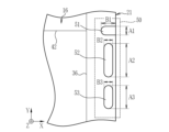
図5に示すように、第1インジケータ51は前面16の辺に垂直な方向に長い形状であり、かつ、第2インジケータ52は前面16の辺に平行な方向に長い形状である。また、第3インジケータ53は、第2インジケータ52と同様に、前面16の辺に平行な方向に長い形状である。例えば、右辺の表示部50の第1インジケータ51、第2インジケータ52、及び、第3インジケータ53のY方向の長さをそれぞれ「A1」「A2」及び「A3」とし、X方向の長さをそれぞれ「B1」「B2」及び「B3」とする。この場合、第1インジケータ51については「A1<B1」である。このように第1インジケータ51を、その第1インジケータ51がある辺(図5においては前面16における右辺)に垂直な方向に長い形状とすることで、直感的に撮影領域の中心の方向を示唆することができる。 As shown in FIG. 5 , the first indicator 51 has a shape elongated in the direction perpendicular to the sides of the front surface 16 , and the second indicator 52 has a shape elongated in the direction parallel to the sides of the front surface 16 . Further, the third indicator 53 has a shape elongated in a direction parallel to the sides of the front surface 16, similarly to the second indicator 52. As shown in FIG. For example, let the lengths in the Y direction of the first indicator 51, the second indicator 52, and the third indicator 53 of the display section 50 on the right side be "A1," "A2," and "A3," respectively, and the lengths in the X direction be Let them be "B1", "B2" and "B3" respectively. In this case, the first indicator 51 is "A1<B1". Thus, by making the first indicator 51 elongate in the direction perpendicular to the side on which the first indicator 51 is located (the right side of the front surface 16 in FIG. 5), the direction of the center of the imaging area is intuitively indicated. can do.

第2インジケータ52については「A2>B2」である。このように第2インジケータ52を、その第2インジケータ52がある辺に平行な方向に長い形状とすることで、前面16に被写体等が重畳した場合でも、被写体等によって第2インジケータ52を隠れ難くし、前面16側から、より確実に第2インジケータ52を確認できるようにすることができる。 As for the second indicator 52, "A2>B2". By making the second indicator 52 long in the direction parallel to the side on which the second indicator 52 is located in this way, even if a subject or the like overlaps the front surface 16, the second indicator 52 is less likely to be hidden by the subject or the like. However, the second indicator 52 can be confirmed more reliably from the front surface 16 side.

第3インジケータ53については「A3>B3」である。このように第3インジケータ53を、その第3インジケータ53がある辺に平行な方向に長い形状とすることで、前面16に被写体等が重畳した場合でも、被写体等によって第3インジケータ53を隠れ難くし、前面16側から、より確実に第3インジケータ53を確認できるようにするためである。 As for the third indicator 53, "A3>B3". By making the third indicator 53 elongated in the direction parallel to the side on which the third indicator 53 is located in this manner, even when a subject or the like overlaps with the front surface 16, the third indicator 53 is less likely to be hidden by the subject or the like. However, the third indicator 53 can be confirmed more reliably from the front surface 16 side.

また、相対的には、第1インジケータ51、第2インジケータ52、第3インジケータ53のうち、第2インジケータ52の辺に沿った長さを最も長くする。すなわち「A2>A1」かつ「A2>A3」とする。本実施形態においては「A2>A3>A1」である。このように、第2インジケータ52の長さを相対的に最も長くすることで、第2インジケータ52が最も目立つようになる。その結果、第1インジケータ51及び第3インジケータ53と第2インジケータ52が並んでいても、放射線技師は、放射線画像の検出の可否を正しくかつ確実に認識できる。 Relatively, among the first indicator 51, the second indicator 52, and the third indicator 53, the length along the side of the second indicator 52 is the longest. That is, "A2>A1" and "A2>A3". In this embodiment, "A2>A3>A1". Thus, by making the length of the second indicator 52 relatively longest, the second indicator 52 becomes most conspicuous. As a result, even if the first indicator 51, the third indicator 53, and the second indicator 52 are arranged side by side, the radiological technologist can correctly and reliably recognize whether or not the radiographic image can be detected.

また、前面16における第1インジケータ51と第2インジケータ52の表示面積を比較する場合、前面16における第2インジケータ52の表示面積が、前面16における第1インジケータ51の表示面積よりも大きい。また、第3インジケータ53も含めて表示面積を比較する場合には、第2インジケータ52の表示面積が最も大きい。すなわち、第1インジケータ51の表示面積を「S1」、第2インジケータ52の表示面積を「S2」、及び、第3インジケータ53の表示面積を「S3」とする場合(いずれも図示しない)、少なくとも「S2>S1」かつ「S2>S3」とする。このように、第2インジケータ52の表示面積を相対的に大きくしておくことで、第2インジケータ52が最も目立つようになる。その結果、第1インジケータ51及び第3インジケータ53と第2インジケータ52が並んでいても、放射線技師は、放射線画像の検出の可否を正しくかつ確実に認識できる。 When comparing the display areas of the first indicator 51 and the second indicator 52 on the front surface 16 , the display area of the second indicator 52 on the front surface 16 is larger than the display area of the first indicator 51 on the front surface 16 . When comparing the display areas including the third indicator 53, the display area of the second indicator 52 is the largest. That is, when the display area of the first indicator 51 is "S1", the display area of the second indicator 52 is "S2", and the display area of the third indicator 53 is "S3" (neither is shown), at least Assume that "S2>S1" and "S2>S3". By relatively increasing the display area of the second indicator 52 in this manner, the second indicator 52 becomes most conspicuous. As a result, even if the first indicator 51, the third indicator 53, and the second indicator 52 are arranged side by side, the radiological technologist can correctly and reliably recognize whether or not the radiographic image can be detected.

なお、上記のように第1インジケータ51、第2インジケータ52、及び、第3インジケータ53の表示面積を比較する場合、図6に示すように、前面16の平面部分だけを考慮して比較してもよい。電子カセッテ10を前面16から見る場合、前面16の平面部分における表示面積の大小関係が、各インジケータの相対的な視認性において支配的だからである。具体的には、例えば、前面16の右辺において、領域R1までが平面であり、領域R2以降が面取り等によって湾曲している場合、領域R1の範囲内にある第1インジケータ51、第2インジケータ52、及び、第3インジケータ53の各表示面積(図6におけるハッチング部分の面積)をσ1、σ2、及びσ3とする場合、少なくとも「σ2>σ1」かつ「σ2>σ3」とする。もちろん、「S2>S1」かつ「S2>S3」と、「σ2>σ1」かつ「σ2>σ3」と、を満たすことが好ましい。 When comparing the display areas of the first indicator 51, the second indicator 52, and the third indicator 53 as described above, as shown in FIG. good too. This is because when the electronic cassette 10 is viewed from the front surface 16, the relative visibility of each indicator is dominated by the size relationship of the display area on the plane portion of the front surface 16. FIG. Specifically, for example, in the right side of the front surface 16, when up to the region R1 is flat and the region after the region R2 is curved by chamfering or the like, the first indicator 51 and the second indicator 52 within the range of the region R1 , and when the display areas of the third indicator 53 (the areas of the hatched portions in FIG. 6) are σ1, σ2, and σ3, at least “σ2>σ1” and “σ2>σ3”. Of course, it is preferable to satisfy "S2>S1" and "S2>S3" and "σ2>σ1" and "σ2>σ3".

図7に示すように、電子カセッテ10は、前面板91、フレーム92、及び、背面板93を有する。前面板91、フレーム92、及び、背面板93は、電子カセッテ10の筐体を構成し、その内部に画像検出部94を収容する。 As shown in FIG. 7, the electronic cassette 10 has a front plate 91, a frame 92, and a rear plate 93. As shown in FIG. The front panel 91, frame 92, and rear panel 93 constitute a housing of the electronic cassette 10, and accommodates an image detection section 94 therein.

前面板91は、電子カセッテ10の前面16を構成する部材であり、少なくとも画像検出部94の部分はカーボン等の放射線を透過する材料を用いて形成する。フレーム92は、電子カセッテ10の側面21~24を構成する部材であり、例えば、アルミニウム等の軽量な金属を用いて形成する。背面板93は、電子カセッテ10の背面17を構成する部材であり、例えば、フレーム92と同様に、アルミニウム等の軽量な金属を用いて形成する。 The front panel 91 is a member forming the front surface 16 of the electronic cassette 10, and at least the image detecting section 94 is formed using a radiation-transmitting material such as carbon. The frame 92 is a member forming the side surfaces 21 to 24 of the electronic cassette 10, and is made of a lightweight metal such as aluminum. The back panel 93 is a member forming the back surface 17 of the electronic cassette 10, and is made of a lightweight metal such as aluminum, for example, like the frame 92. As shown in FIG.

画像検出部94は、被写体を透過した放射線を用いて、被写体の放射線画像を検出する。電子カセッテ10においては、画像検出部94として、放射線を直接的に電気信号に変換する直接変換型の検出器と、放射線を可視光に変換し、その可視光を光電変換する間接変換型の検出器のいずれをも使用できる。本実施形態では、画像検出部94は間接変換型である。画像検出部94の背面17側には、鉛板等の放射線を遮蔽する放射線遮蔽部95を介して、画像検出部94及びその他電子カセッテ10の各部を制御する制御基板96を有する。制御基板96には、図示しないフレキシブル基板等を含む。 The image detection unit 94 detects a radiographic image of a subject using radiation that has passed through the subject. In the electronic cassette 10, the image detection unit 94 includes a direct conversion detector that converts radiation directly into an electrical signal, and an indirect conversion detector that converts radiation into visible light and photoelectrically converts the visible light. You can use any of the utensils. In this embodiment, the image detection unit 94 is of the indirect conversion type. A control board 96 for controlling the image detection section 94 and other parts of the electronic cassette 10 is provided on the rear surface 17 side of the image detection section 94 via a radiation shielding section 95 such as a lead plate that shields radiation. The control board 96 includes a flexible board (not shown) and the like.

また、表示部50を構成する各インジケータは、発光体と、発光体が発光する光を導光する導光体と、発光体の発光及び発光量等を制御することにより、インジケータを制御する基板と、を有する。発光体とは、LED(light emitting diode)等の半導体発光素子、または電熱線もしくはガス等を用いるランプ等である。本実施形態においては、発光体はLEDである。このため、例えば、第2インジケータ52は、発光体である第2インジケータ用LED102と、第2導光体112と、LED基板109と、を含む。第2インジケータ用LED102は、制御基板96とは別体のLED基板109に設けられている。LED基板109は、第2インジケータ52を制御する基板である。インジケータを制御するとは、インジケータの点灯または消灯、及び、発光量等を制御することをいう。LED基板109は、第2インジケータ用LED102の発光及び発光量等を制御する。その結果、LED基板109は、第2インジケータ52を制御する。LED基板109は、固定部材110によって例えばフレーム92に接続され、XYZの各方向のいずれかまたは複数に移動可能となっている。電子カセッテ10に加わる振動等を吸収するためである。第2インジケータ用LED102は緑色光を発光する。第2導光体112は、第2インジケータ用LED102が発光する光を受け、これを導光する第1部分C1と、第1部分C1に接続し、かつ、表面の一部を前面16に露呈する第2部分C2と、の2段構成となっている。 In addition, each indicator that constitutes the display unit 50 includes a light emitter, a light guide that guides the light emitted by the light emitter, and a substrate that controls the indicator by controlling the light emission and the amount of light emitted by the light emitter. and have The luminous body is a semiconductor light emitting element such as an LED (light emitting diode), or a lamp using a heating wire, gas, or the like. In this embodiment, the light emitters are LEDs. Therefore, for example, the second indicator 52 includes a second indicator LED 102 that is a light emitter, a second light guide 112 and an LED substrate 109 . The second indicator LED 102 is provided on an LED board 109 that is separate from the control board 96 . The LED board 109 is a board that controls the second indicator 52 . Controlling the indicator means controlling the lighting or extinguishing of the indicator, the amount of light emitted, and the like. The LED board 109 controls the light emission of the second indicator LED 102, the amount of light emission, and the like. As a result, the LED board 109 controls the second indicator 52 . The LED board 109 is connected to, for example, the frame 92 by a fixing member 110, and is movable in one or more of the XYZ directions. This is for absorbing vibrations and the like applied to the electronic cassette 10 . The second indicator LED 102 emits green light. The second light guide 112 receives and guides the light emitted by the second indicator LED 102, and is connected to the first portion C1 and has a part of the surface exposed to the front surface 16. It has a two-stage configuration of a second portion C2 that

第2導光体112の第2部分C2が前面16に露呈する表面は、本実施形態においては前面16と面一である。ただし、第2導光体112の第2部分C2が前面16に露呈する表面は、前面16に対して凹んでいてもよい。第2導光体112の第2部分C2が前面16に露呈する表面が、前面16と面一である場合、または、前面16に対して凹んでいる場合、撮影時に第2導光体112が被写体等に引っ掛かる不具合、及び、被写体等の引っ掛かりによって第2導光体112が破損または変形等する不具合を低減できる。第1インジケータ51及び第3インジケータについても同様である。さらに、電子カセッテ10は、画像検出部94に対してLED基板109を遮光する第1遮光部120を備える。 The surface where the second portion C2 of the second light guide 112 is exposed on the front surface 16 is flush with the front surface 16 in this embodiment. However, the surface where the second portion C<b>2 of the second light guide 112 is exposed on the front surface 16 may be recessed with respect to the front surface 16 . When the surface where the second portion C2 of the second light guide 112 is exposed on the front surface 16 is flush with the front surface 16, or when it is recessed with respect to the front surface 16, the second light guide 112 is It is possible to reduce the inconvenience of being caught by a subject or the like and the damage or deformation of the second light guide body 112 due to being caught by a subject or the like. The same applies to the first indicator 51 and the third indicator. Further, the electronic cassette 10 includes a first light shielding section 120 that shields the LED board 109 from the image detection section 94 .

図8に示すように、第1インジケータ51及び第3インジケータ53についても、上記第2インジケータ52と同様の構成となっている。具体的には、第1インジケータ51は、第1インジケータ用LED101と、第1導光体111と、を含む。第1インジケータ用LED101は発光色が可変である。このため、第1インジケータ用LED101の発光色を変更することにより、第1インジケータ51の表示色を変更することができる。また、第1導光体111は、第1インジケータ用LED101が発光する光を受け、これを導光する第1部分と、第1部分に接続し、かつ、表面の一部を前面16に露呈する第2部分と、2段構成となっている点は、第2導光体112と同様である。ただし、第1導光体111は、第1インジケータ51の形状等に合わせて形作られており、例えば、第2導光体112とは異なり、第2部分はX方向において第1部分から突出する形状となっている。 As shown in FIG. 8, the first indicator 51 and the third indicator 53 also have the same configuration as the second indicator 52 described above. Specifically, the first indicator 51 includes a first indicator LED 101 and a first light guide 111 . The first indicator LED 101 has a variable emission color. Therefore, the display color of the first indicator 51 can be changed by changing the emission color of the first indicator LED 101 . The first light guide 111 receives and guides the light emitted by the first indicator LED 101 , and is connected to the first part and exposes part of the surface to the front surface 16 . It is the same as the second light guide 112 in that it has a second portion and a two-stage structure. However, the first light guide 111 is shaped according to the shape of the first indicator 51, etc. For example, unlike the second light guide 112, the second portion protrudes from the first portion in the X direction. It has a shape.

また、第3インジケータ53は、第3インジケータ用LED103と、第3導光体113と、を含む。第3インジケータ用LED103は、本実施形態においては例えば白色等の特定の色に発光する。第3導光体113は、第3インジケータ用LED103が発光する光を受け、これを導光する第1部分と、第1部分に接続し、かつ、表面の一部を前面16に露呈する第2部分と、の2段構成になっている点は、第1導光体111及び第2導光体112と同様である。ただし、第3導光体113は、第3インジケータ53の大きさ及び形状等に形作られている。本実施形態においては、第3導光体113は、図7における第2導光体112と同様に、第2部分が第1部分の上(Z方向正側)に接続し、第1部分のY方向正側の端部と、第2部分のY方向正側の端部と、は面一である。 Also, the third indicator 53 includes a third indicator LED 103 and a third light guide 113 . The third indicator LED 103 emits light in a specific color such as white in this embodiment. The third light guide 113 receives the light emitted by the third indicator LED 103 and guides the light. It is the same as the first light guide 111 and the second light guide 112 in that it has a two-stage configuration of two parts. However, the third light guide 113 is formed in the size, shape, etc. of the third indicator 53 . In the present embodiment, the third light guide 113 has the second portion connected to the top of the first portion (positive side in the Z direction), similar to the second light guide 112 in FIG. The Y-direction positive side end and the Y-direction positive side end of the second portion are flush with each other.

本実施形態においては、第1インジケータ用LED101及び第3インジケータ用LED103は、第2インジケータ用LED102と共通のLED基板109に設けられている。そして、第1遮光部120は、画像検出部94に対して、第1インジケータ用LED101、第2インジケータ用LED102、及び、第3インジケータ用LED103を含むLED基板109の全体を覆う。このため、第1遮光部120は、画像検出部94に対して、第1インジケータ51を制御する基板(LED基板109)、第2インジケータ52を制御する基板(LED基板109)、及び、第3インジケータ53を制御する基板(LED基板109)から遮光する。第1遮光部120は、例えば、黒色のスポンジまたはテープ等である。このように、第1遮光部120を設けることにより、LED基板109に設けた各インジケータ用のLEDが発する各光が、画像検出部94に漏れることを防止または低減できる。本実施形態のように、画像検出部94が間接変換型の検出器である場合、LED基板109から画像検出部94に光が漏れると、撮影する放射線画像においてアーチファクトになる。このため、第1遮光部120は、放射線画像のアーチファクトを防止または低減することができる。 In the present embodiment, the first indicator LED 101 and the third indicator LED 103 are provided on the LED substrate 109 common to the second indicator LED 102 . The first light shielding section 120 covers the entire LED substrate 109 including the first indicator LED 101 , the second indicator LED 102 , and the third indicator LED 103 with respect to the image detection section 94 . Therefore, the first light shielding unit 120 provides the image detection unit 94 with a substrate (LED substrate 109) that controls the first indicator 51, a substrate (LED substrate 109) that controls the second indicator 52, and a third LED substrate. The substrate (LED substrate 109) that controls the indicator 53 is shielded from light. The first light shielding part 120 is, for example, a black sponge or tape. By providing the first light shielding section 120 in this way, it is possible to prevent or reduce the leakage of the light emitted by the indicator LEDs provided on the LED board 109 to the image detecting section 94 . When the image detection unit 94 is an indirect conversion type detector as in the present embodiment, if light leaks from the LED substrate 109 to the image detection unit 94, artifacts will occur in the captured radiographic image. Therefore, the first light shielding unit 120 can prevent or reduce artifacts in radiographic images.

なお、第1インジケータ用LED101、第2インジケータ用LED102、及び、第3インジケータ用LED103は、それぞれ別のLED基板に設けることができる。また、第1インジケータ用LED101、第2インジケータ用LED102、及び、第3インジケータ用LED103のうち1つのみを別基板に設けることができる。これらの場合、第1遮光部120は、これらのLEDを実装した各基板を覆うことによって画像検出部94を各LEDが発する光から遮光してもよく、これらのLED実装した各基板の全体を覆うことによって画像検出部94を各LEDが発する光から遮光してもよい。 The first indicator LED 101, the second indicator LED 102, and the third indicator LED 103 can be provided on separate LED boards. Also, only one of the first indicator LED 101, the second indicator LED 102, and the third indicator LED 103 can be provided on a separate substrate. In these cases, the first light shielding section 120 may shield the image detection section 94 from the light emitted by each LED by covering each board on which these LEDs are mounted, and the entirety of each board on which these LEDs are mounted may be blocked. The image detector 94 may be shielded from the light emitted by each LED by covering it.

また、インジケータ等のLED等の発光体は、画像検出部94の制御基板96上に実装し、制御基板96上の発光体から導光する構成とすれば低コスト化できるが、本実施形態においては上記の通り、第1インジケータ51、第2インジケータ52、及び、第3インジケータ53を構成するLED基板109を、画像検出部94の制御基板96とは別の基板としている。これは、上記のようにLED基板109の全体を第1遮光部120で覆うことにより、より確実に画像検出部94への光かぶり(光漏れ)を防ぐためである。すなわち、LED基板109を、画像検出部94の制御基板96とは別の基板とし、これを覆うように第1遮光部120を設けることで、画像検出部94への光かぶりをより確実に防いでいる。その結果、電子カセッテ10は前面16に複数の発光するインジケータを設けているにもかかわらず、これらのインジケータからの光かぶりによるアーチファクトがなく、または少ない正確な放射線画像を得ることができる。 In addition, if a light emitter such as an LED such as an indicator is mounted on the control board 96 of the image detection unit 94 and the light is guided from the light emitter on the control board 96, the cost can be reduced. As described above, the LED board 109 constituting the first indicator 51 , the second indicator 52 , and the third indicator 53 is a board different from the control board 96 of the image detection section 94 . This is because covering the entire LED substrate 109 with the first light shielding portion 120 as described above more reliably prevents light fogging (light leakage) to the image detecting portion 94 . That is, by using the LED board 109 as a board different from the control board 96 of the image detection section 94 and providing the first light blocking section 120 so as to cover it, the image detection section 94 is more reliably prevented from being exposed to light. I'm in. As a result, even though the electronic cassette 10 has a plurality of luminous indicators on the front face 16, an accurate radiographic image can be obtained with little or no artifacts due to light fog from these indicators.

さらに、電子カセッテ10は、隣接する第1インジケータ51と第2インジケータ52の間に、第1インジケータ51と第2インジケータ52を互いに遮光する第2遮光部121を備える。同様に、電子カセッテ10は、隣接する第2インジケータ52と第3インジケータ53との間に、第2インジケータ52と第3インジケータ53を互いに遮光する第2遮光部122を備える。 Further, the electronic cassette 10 is provided with a second light shielding part 121 between the first indicator 51 and the second indicator 52 adjacent to each other and shielding the first indicator 51 and the second indicator 52 from light. Similarly, the electronic cassette 10 includes a second light shielding section 122 between the adjacent second indicator 52 and third indicator 53 for shielding the second indicator 52 and the third indicator 53 from light.

これら第2遮光部121及び122は、フレーム92が形成する(図8参照)。すなわち、第1導光体111、第2導光体112、及び、第3導光体113は、フレーム92の一部を概ねその形状に切り欠いた溝部分に嵌め込む構成となっている。このため、第1導光体111と第2導光体112の間に残るフレーム92の部分が、第2遮光部121を構成する。また、第2導光体112と第3導光体113の間に残るフレーム92の部分が、第2遮光部122を構成する。第1導光体111と第2導光体112の間に設ける第2遮光部121は、第1導光体111及び第2導光体112の相互間の光漏れを防止する。その結果、第1インジケータ51を点灯した場合に、点灯していない第2インジケータ52が点灯している用に見えてしまうこと、及び、第2インジケータ52を点灯した場合に、点灯していない第1インジケータ51が点灯してるように見えてしまうことを防ぐことができる。また、第2遮光部121は、第1インジケータ51と第2インジケータ52の混色も防止する。このため、第1インジケータ51と第2インジケータ52は、所定の表示色で正しく点灯することができる。同様に、第2導光体112と第3導光体113の間に設ける第2遮光部122は、第2導光体112と第3導光体113の相互間の光漏れを防止する。その結果、第2遮光部122は、第2インジケータ52と第3インジケータ53の点灯の誤認、及び、混色を防止することができる。 These second light shields 121 and 122 are formed by a frame 92 (see FIG. 8). In other words, the first light guide 111, the second light guide 112, and the third light guide 113 are configured such that a part of the frame 92 is fitted into grooves that are notched in the approximate shape thereof. Therefore, the portion of the frame 92 remaining between the first light guide 111 and the second light guide 112 constitutes the second light shielding portion 121 . A portion of the frame 92 remaining between the second light guide 112 and the third light guide 113 constitutes the second light shielding portion 122 . A second light shield 121 provided between the first light guide 111 and the second light guide 112 prevents light leakage between the first light guide 111 and the second light guide 112 . As a result, when the first indicator 51 is lit, the second indicator 52, which is not lit, appears to be lit. 1 indicator 51 can be prevented from appearing to be lit. In addition, the second light shielding portion 121 also prevents color mixing between the first indicator 51 and the second indicator 52 . Therefore, the first indicator 51 and the second indicator 52 can be correctly lit with predetermined display colors. Similarly, the second light shielding part 122 provided between the second light guide 112 and the third light guide 113 prevents light leakage between the second light guide 112 and the third light guide 113 . As a result, the second light shielding portion 122 can prevent false recognition of lighting of the second indicator 52 and the third indicator 53 and color mixture.

また、第2遮光部121及び122をフレーム92によって形成する場合、第1導光体111、第2導光体112、及び第3導光体113を嵌め込むために削る部分が最小限で済む。このため、表示部50に係る部分及びその周辺の全体を切り欠いて、第1インジケータ51、第2インジケータ52、及び、第3インジケータ53を配置する場合と比較すると、フレーム92の剛性を保つことができるという利点もある。 Also, when the second light shielding parts 121 and 122 are formed by the frame 92, the parts to be scraped for fitting the first light guide 111, the second light guide 112, and the third light guide 113 can be minimized. . Therefore, compared to the case where the first indicator 51, the second indicator 52, and the third indicator 53 are arranged by cutting out the portion related to the display section 50 and the entire periphery thereof, the rigidity of the frame 92 can be maintained. There is also the advantage of being able to

また、少なくとも第1インジケータ51、第2インジケータ52、及び、第3インジケータ53を形成する部分において、フレーム92は第1段部分131と第2段部分132の2段構成になっている。第1段部分131は第1導光体111、第2導光体112、及び第3導光体113の第1部分(図7における第2導光体112の第1部分C1等)を嵌め込む穴を構成する部分である。第2段部分132は、第1段部分131からZ方向正側に突出した部分であり、少なくとも第2導光体112の第2部分C2及び第3導光体113の第2部分のX方向正側及びY方向の側面を覆う。 In addition, the frame 92 has a two-step configuration of a first step portion 131 and a second step portion 132 at least at the portions forming the first indicator 51, the second indicator 52, and the third indicator 53. As shown in FIG. The first step portion 131 is fitted with the first portions of the first light guide 111, the second light guide 112, and the third light guide 113 (the first portion C1 of the second light guide 112 in FIG. 7, etc.). It is the part that constitutes the hole for insertion. The second stepped portion 132 is a portion that protrudes from the first stepped portion 131 to the positive side in the Z direction, and is at least the second portion C2 of the second light guide 112 and the second portion of the third light guide 113 in the X direction. Cover the positive and Y direction sides.

図9に示すように、フレーム92が上記のように第1段部分131及び第2段部分132の2段構成になっておらず、第2導光体112及び第3導光体113の第2部分がフレーム92内で露呈している場合、例えば、第2インジケータ52を点灯すると、前面板91とフレーム92の境界140に沿って光漏れ141が生じる。このような光漏れ141は、第1部分C1のY方向正側の端部と第2部分C2のY方向正側の端部とが面一である場合に生じやすい。このため、少なくともこの構造を有する第2導光体112及び第3導光体113のまわりに第2段部分132を設け、フレーム92と前面板91との境界140と、第2導光体112及び第3導光体113とフレーム92との境界と、が重複しない構造とする。これにより、光漏れ141を防ぎまたは低減し、第2インジケータ52及び第3インジケータ53を、前面16に露呈する形状で正しく点灯することができる。 As shown in FIG. 9, the frame 92 does not have the two-stage structure of the first step portion 131 and the second step portion 132 as described above, and the second light guide 112 and the third light guide 113 are arranged in two stages. If two portions are exposed within the frame 92 , for example, when the second indicator 52 is lit, light leakage 141 occurs along the interface 140 between the front panel 91 and the frame 92 . Such light leakage 141 is likely to occur when the end portion of the first portion C1 on the positive side in the Y direction and the end portion of the second portion C2 on the positive side in the Y direction are flush with each other. For this reason, a second step portion 132 is provided around the second light guide 112 and the third light guide 113 having at least this structure, and a boundary 140 between the frame 92 and the front panel 91 and the second light guide 112 and the boundary between the third light guide 113 and the frame 92 do not overlap each other. This prevents or reduces the light leakage 141 and allows the second indicator 52 and the third indicator 53 to be properly illuminated in a shape exposed to the front surface 16 .

なお、上記実施形態においては、第2インジケータ52は、点灯することによってレディ状態を表し、消灯することによって非レディ状態を表すが、第2インジケータ52はさらに点滅することによって、電子カセッテ10の他の状態を表すことができる。例えば、第2インジケータ52は、点滅することにより、電子カセッテ10または電子カセッテ10を使用するシステムが起動中(準備動作中)であること等の状態を表すことができる。第2インジケータ52が点滅により、レディ状態及び非レディ状態以外の電子カセッテ10の状態を表す場合、前面16または表示部50にインジケータを追加することなく、前面16において報知できる電子カセッテ10の状態の種類を増やすことができる。同様に、第1インジケータ51は点灯することによって撮影領域の中心及び電子カセッテ10の識別情報を表示するが、第1インジケータ51は点滅することによって電子カセッテ10の他の状態を表示することができる。また、第3インジケータ53は点灯することよって、画像検出部94の向きを表示するが、第3インジケータ53は点滅することによって別の電子カセッテ10の他の状態を表示することができる。このように、第1インジケータ51または第3インジケータ53の点滅によって電子カセッテ10の状態を表示する場合も、前面16または表示部50にインジケータを追加することなく、前面16において報知できる電子カセッテ10の状態の種類を増やすことができる。 In the above embodiment, the second indicator 52 lights to indicate the ready state and goes off to indicate the non-ready state. can represent the state of For example, the second indicator 52 blinks to indicate that the electronic cassette 10 or the system using the electronic cassette 10 is starting up (preparing). When the second indicator 52 flashes to indicate a status of the electronic cassette 10 other than the ready status and the non-ready status, the status of the electronic cassette 10 can be notified on the front face 16 without adding an indicator to the front face 16 or the display section 50. types can be increased. Similarly, the first indicator 51 lights to display the center of the imaging area and the identification information of the electronic cassette 10, but the first indicator 51 can display other states of the electronic cassette 10 by blinking. . Also, the third indicator 53 lights to indicate the orientation of the image detection unit 94 , but blinks to indicate another state of the electronic cassette 10 . In this way, even when the state of the electronic cassette 10 is displayed by blinking the first indicator 51 or the third indicator 53, the electronic cassette 10 can be notified on the front surface 16 without adding an indicator to the front surface 16 or the display unit 50. You can add more types of states.

上記実施形態においては、第1インジケータ51及び第3インジケータ53と比較して、第2インジケータ52の輝度を大きくすることにより、第2インジケータ52を最も明るく点灯するが、第2インジケータ52は輝度を大きくする以外の方法で相対的に最も明るく点灯してもよい。すなわち、第1インジケータ51、第2インジケータ52、及び、第3インジケータ53の明るさの比較は、輝度以外の情報を用いて行うことができる。具体的には、第2インジケータ52の光度または光束(ルーメン)等を、第1インジケータ51及び第3インジケータ53よりも大きくすることにより、第2インジケータ52を相対的に最も明るく点灯することができる。また、第1インジケータ51、第2インジケータ52、及び、第3インジケータ53の明るさは、輝度、光度、または光束等の各インジケータの発光に関するステータスだけでなく、比視感度(明所における比視感度及び/または暗所における比視感度)を考慮して定めることが特に好ましい。第1インジケータ51、第2インジケータ52、及び、第3インジケータ53の各表示色を考慮して、電子カセッテ10の実際的な使用環境において放射線技師が第2インジケータ52を相対的に最も明るく認識できるようにするためである。例えば、輝度、光度または光束等と比視感度との積(または当該積の波長についての積分値)が相対的に最も大きくなるようにすることで、第2インジケータ52を相対的に最も明るく点灯することが好ましい。 In the above embodiment, the brightness of the second indicator 52 is increased compared to the first indicator 51 and the third indicator 53 so that the second indicator 52 is lit most brightly. It may be illuminated relatively brightest in a manner other than enlarging it. That is, the comparison of the brightness of the first indicator 51, the second indicator 52, and the third indicator 53 can be performed using information other than luminance. Specifically, by making the luminous intensity or luminous flux (lumens) of the second indicator 52 greater than those of the first indicator 51 and the third indicator 53, the second indicator 52 can be illuminated relatively brightest. . In addition, the brightness of the first indicator 51, the second indicator 52, and the third indicator 53 is determined not only by the status of light emission of each indicator such as luminance, luminous intensity, or luminous flux, but also by relative luminosity (comparative luminosity in a bright place). It is particularly preferable to determine the sensitivity and/or relative luminosity in a dark place. Considering the respective display colors of the first indicator 51, the second indicator 52, and the third indicator 53, the radiologist can recognize the second indicator 52 relatively brightest in the actual usage environment of the electronic cassette 10. This is to ensure that For example, by making the product of luminance, luminous intensity, luminous flux, etc. and relative luminous efficiency (or the integrated value of the product with respect to the wavelength) relatively large, the second indicator 52 is lit relatively brightly. preferably.

上記実施形態においては、第2インジケータ52の表示色を不変の固定色としているが、第2インジケータ52の表示色を変更できるようにしてもよい。第2インジケータ52の表示色が可変である場合、例えば、正常動作時の点灯では第2インジケータ52を上記実施形態の固定色(緑色)で点灯し、かつ、エラー発生時の点灯では上記実施形態の固定色以外の色で第2インジケータ52を点灯する。このように、第2インジケータ52の表示色を可変にすると、表示部50にインジケータを追加することなく、第2インジケータ52の表示色またはその変化によって、電子カセッテ10の前面16でレディ状態以外の電子カセッテ10の状態を表示することができる。 In the above embodiment, the display color of the second indicator 52 is a fixed color, but the display color of the second indicator 52 may be changed. When the display color of the second indicator 52 is variable, for example, the second indicator 52 is lit in the fixed color (green) of the above embodiment when lighting during normal operation, and when lighting when an error occurs, the second indicator 52 is lit in the above embodiment. The second indicator 52 is lit in a color other than the fixed color of . In this way, if the display color of the second indicator 52 is made variable, the display color of the second indicator 52 or a change in the display color can be used without adding an indicator to the display unit 50, and the front surface 16 of the electronic cassette 10 can be displayed in a state other than the ready state. The status of the electronic cassette 10 can be displayed.

なお、上記実施形態の通り、電子カセッテ10の各辺にある表示部50は、第1インジケータ51、第2インジケータ52、及び、第3インジケータ53の配列が撮影領域の中心の方向から見て同じ配列順となる対称性を有し、概ね点対称(回転対称)の配列順となっている。上記実施形態では、撮影中心から見て左から第1インジケータ51、第2インジケータ52、及び第3インジケータ53の配列順である(図1等参照)。このように、電子カセッテ10の各辺に設ける表示部50において、各インジケータの配列順を点対称の配列順にすると、第1インジケータ51、第2インジケータ52、及び、第3インジケータ53を制御するLED基板109等を各表示部50で同一の部品にすることができる。その結果、複数の表示部50を電子カセッテ10に設けることによるコストを低減できる。 As in the above embodiment, the display units 50 on each side of the electronic cassette 10 have the same arrangement of the first indicator 51, the second indicator 52, and the third indicator 53 when viewed from the direction of the center of the imaging area. It has a symmetry that is the order of arrangement, and the arrangement order is generally point-symmetrical (rotationally symmetrical). In the above-described embodiment, the order of arrangement is the first indicator 51, the second indicator 52, and the third indicator 53 from the left when viewed from the imaging center (see FIG. 1, etc.). As described above, in the display unit 50 provided on each side of the electronic cassette 10, if the arrangement order of the respective indicators is arranged in a point-symmetrical arrangement order, the LEDs that control the first indicator 51, the second indicator 52, and the third indicator 53 The substrate 109 or the like can be the same component in each display section 50 . As a result, the cost for providing a plurality of display units 50 in the electronic cassette 10 can be reduced.

また、上記実施形態では、上記の通り、第1インジケータ51、第2インジケータ52、及び、第3インジケータ53は点対称の配列順であることが好ましいが、これらの配列順は、X方向またはY方向に線対称な配列順にすることができる。このように各表示部50の第1インジケータ51、第2インジケータ52、及び第3インジケータ53の配列を線対称な配列順にする場合、電子カセッテ10の4辺に設ける表示部50のうち2つの表示部50で配列順が同じになる。このため、これらのLED基板109等を同じ部品にすることができるので、各辺でインジケータの配列順が異なる場合と比較すると、コストを低減できる。具体的には、上辺及び下辺の表示部50においては、X方向に沿って左(X方向負側)から第1インジケータ51、第2インジケータ52、及び、第3インジケータ53の配列順とし、かつ、右辺及び左辺の表示部50においては、Y方向に沿って上(Y方向正側)から第1インジケータ51、第2インジケータ52、及び、第3インジケータ53の配列順とすることができる。この場合、上辺と右辺の表示部50でインジケータの配列順が同じになり、かつ、下辺と左辺の表示部50でインジケータの配列順が同じになるので、上辺と右辺の表示部50でLED基板109等を同じ部品にでき、かつ、下辺と左辺の表示部50でLED基板109等を同じ部品にできる。 In the above-described embodiment, as described above, the first indicator 51, the second indicator 52, and the third indicator 53 are preferably arranged in a point-symmetric arrangement order. The arrangement order can be symmetrical in the direction. When the first indicator 51, the second indicator 52, and the third indicator 53 of each display unit 50 are arranged in line-symmetrical order, two of the display units 50 provided on the four sides of the electronic cassette 10 are displayed. In section 50, the arrangement order becomes the same. Therefore, the LED substrate 109 and the like can be used as the same parts, so the cost can be reduced compared to the case where the indicators are arranged in different order on each side. Specifically, in the display portions 50 on the upper and lower sides, the first indicator 51, the second indicator 52, and the third indicator 53 are arranged from the left (the negative side in the X direction) along the X direction, and , the right side and the left side of the display section 50, the first indicator 51, the second indicator 52, and the third indicator 53 can be arranged in order from the top (the positive side in the Y direction) along the Y direction. In this case, the display units 50 on the upper side and the right side have the same arrangement order of the indicators, and the display units 50 on the lower side and the left side have the same arrangement order of the indicators. 109 and the like can be made the same parts, and the LED substrates 109 and the like can be made the same parts in the lower side and left side display portions 50 .

なお、上記実施形態においては、表示部50は、第1インジケータ51、第2インジケータ52、及び、第3インジケータ53を前面16に直接に露呈する。しかし、図10に示すように、表示部50は、第1インジケータ51、第2インジケータ52、及び、第3インジケータ53の表面を、例えば前面板91と同じ黒色の透明板によって覆い隠す構成とすることができる。この場合、第1インジケータ51、第2インジケータ52、及び、第3インジケータ53は、非点灯状態においてほぼ視認できない。一方、図11に示すように、例えば、第1インジケータ51と第2インジケータ52を点灯すると、その光が上記透明板を透過し、点灯した第1インジケータ51及び第2インジケータ52の表示を視認できる。第3インジケータ53を点灯する場合も同様である。このように、第1インジケータ51、第2インジケータ52、第3インジケータ53の非点灯時に、その存在を隠す透明板を用いて表示部50を構成する場合、必要に応じて各インジケータが現れるので、放射線技師に対して各インジケータの点灯及びその色を強調できる。その結果、放射線技師は、各インジケータが報知する内容を誤りなく知得しやすい。 In addition, in the above embodiment, the display unit 50 directly exposes the first indicator 51 , the second indicator 52 and the third indicator 53 on the front surface 16 . However, as shown in FIG. 10, the display unit 50 has a configuration in which the surfaces of the first indicator 51, the second indicator 52, and the third indicator 53 are covered with, for example, the same black transparent plate as the front plate 91. be able to. In this case, the first indicator 51, the second indicator 52, and the third indicator 53 are almost invisible in the non-lighting state. On the other hand, as shown in FIG. 11, for example, when the first indicator 51 and the second indicator 52 are lit, the light passes through the transparent plate, and the display of the lit first indicator 51 and the second indicator 52 can be visually recognized. . The same applies when the third indicator 53 is lit. In this way, when the display unit 50 is configured using a transparent plate that hides the presence of the first indicator 51, the second indicator 52, and the third indicator 53 when they are not lit, each indicator appears as necessary. The lighting of each indicator and its color can be emphasized to the radiologist. As a result, radiological technologists can easily learn the content reported by each indicator without error.

なお、上記実施形態においては、第1インジケータ51が前面16から側面21~24にまで延伸した形状となっているが、図12及び図13に示すように、第1インジケータ51は背面17まで延伸した形状にしてもよい。この場合、電子カセッテ10の背面17からも、第1インジケータ51が表示する識別色を把握でき、ユーザビリティが向上する。 In the above embodiment, the first indicator 51 extends from the front surface 16 to the side surfaces 21 to 24. However, as shown in FIGS. 12 and 13, the first indicator 51 extends to the rear surface 17. It may be shaped like In this case, the identification color displayed by the first indicator 51 can be grasped also from the rear surface 17 of the electronic cassette 10, thereby improving usability.

また、上記実施形態においては、第1インジケータ51が前面16から側面21~24にまで延伸した形状となっているが、図14及び図15に示すように、第2インジケータ52を側面21~24にまで延伸した形状とすることができる。この場合、側面21~24において第2インジケータ52の点灯を確認することができる。第3インジケータ53も同様に、側面21~24にまで延伸した形状とすることができる。さらに、第2インジケータ52及び第3インジケータ53は、図12及び図13の第1インジケータ51のように、背面17にまで延伸した形状としてもよい。 In the above embodiment, the first indicator 51 extends from the front surface 16 to the side surfaces 21 to 24. However, as shown in FIGS. It can be a shape extended to. In this case, lighting of the second indicator 52 can be confirmed on the side surfaces 21 to 24 . Similarly, the third indicator 53 can also have a shape extending to the side surfaces 21-24. Furthermore, the second indicator 52 and the third indicator 53 may have a shape extending to the rear surface 17 like the first indicator 51 in FIGS.

また、上記実施形態においては、例えば、右辺においてY方向正側から第1インジケータ51、第2インジケータ52、及び、第3インジケータ53の順に各インジケータを配列しているが、表示部50における各インジケータの配列は、第1インジケータ51をクロスライン41または42の延長上に配置すること除き、表示部50における各インジケータの相対的な配列は任意である。このため、図16に示すように、例えば、右辺においてY方向正側から、第2インジケータ52、第1インジケータ51、及び、第3インジケータ53の順に各インジケータを配列することができる。 In the above embodiment, for example, the indicators are arranged in the order of the first indicator 51, the second indicator 52, and the third indicator 53 from the positive side in the Y direction on the right side. , except that the first indicator 51 is arranged on the extension of the cross line 41 or 42, the relative arrangement of each indicator on the display section 50 is arbitrary. Therefore, as shown in FIG. 16, for example, the indicators can be arranged in the order of the second indicator 52, the first indicator 51, and the third indicator 53 from the positive side in the Y direction on the right side.

10 電子カセッテ
16 前面
17 背面
21~24 側面
31~34 マーカ
36~39 ライン
41、42 クロスライン
50 表示部
51 第1インジケータ
52 第2インジケータ
53 第3インジケータ
61~64 ラバー
71 中央部
72 第1背面表示部
73 第2背面表示部
74 充電池パック
81 操作部
81、82 操作部
83~86 背面インジケータ
91 前面板
92 フレーム
93 背面板
94 画像検出部
95 放射線遮蔽部
96 制御基板
101 第1インジケータ用LED
102 第2インジケータ用LED
103 第3インジケータ用LED
109 LED基板
110 固定部材
111 第1導光体
112 第2導光体
113 第3導光体
120 第1遮光部
121、122 第2遮光部
131 第1段部分
132 第2段部分
140 境界
141 光漏れ
10 Electronic Cassette 16 Front 17 Rear 21-24 Side 31-34 Marker 36-39 Line 41, 42 Cross Line 50 Display 51 First Indicator 52 Second Indicator 53 Third Indicator 61-64 Rubber 71 Center 72 First Rear Display section 73 Second rear display section 74 Battery pack 81 Operation section 81, 82 Operation section 83 to 86 Rear indicator 91 Front panel 92 Frame 93 Rear panel 94 Image detection section 95 Radiation shield section 96 Control board 101 First indicator LED
102 LED for second indicator
103 Third indicator LED
109 LED substrate 110 fixing member 111 first light guide 112 second light guide 113 third light guide 120 first light shielding part 121, 122 second light shielding part 131 first stepped portion 132 second stepped portion 140 boundary 141 light leak

Claims (14)

被写体を透過した放射線を用いて、前記被写体の放射線画像を検出する画像検出部であり、被写体を透過した放射線を可視光に変換し、変換した可視光を光電変換する間接変換型の検出器である画像検出部と、
前記画像検出部を収容し、前記放射線画像を検出する場合に前記被写体に向ける前面と、前記前面に対向する背面と、前記前面と前記背面を接続する側面と、を有する筐体と、
前記前面かつ前記画像検出部の撮影領域の外側に設けられ、発光することによって前記撮影領域の中心を示す第1インジケータと、
前記前面かつ前記撮影領域の外側に設けられ、発光することによって前記放射線画像の検出の可否を表す第2インジケータと、
を備え、
前記第1インジケータを制御する基板、及び、前記第2インジケータを制御する基板は、前記画像検出部の制御基板とは別の基板であり、
前記画像検出部を、前記第1インジケータを制御する基板及び前記第2インジケータを制御する基板から遮光する第1遮光部を備える電子カセッテ。
An image detection unit that detects a radiation image of a subject using radiation that has passed through the subject, and an indirect conversion type detector that converts the radiation that has passed through the subject into visible light and photoelectrically converts the converted visible light. an image detector;
a housing containing the image detection unit and having a front surface facing the subject when detecting the radiographic image, a rear surface facing the front surface, and a side surface connecting the front surface and the rear surface;
a first indicator provided on the front surface and outside the imaging area of the image detection unit and indicating the center of the imaging area by emitting light;
a second indicator that is provided on the front surface and outside the imaging region and indicates whether or not the radiographic image can be detected by emitting light;
with
A substrate for controlling the first indicator and a substrate for controlling the second indicator are substrates different from the control substrate of the image detection unit,
An electronic cassette comprising a first light shielding section that shields the image detection section from a board that controls the first indicator and a board that controls the second indicator.
前記第1インジケータと前記第2インジケータの間に、前記第1インジケータと前記第2インジケータを互いに遮光する第2遮光部を備える請求項1に記載の電子カセッテ。 2. The electronic cassette according to claim 1, further comprising a second light shielding part between said first indicator and said second indicator for shielding said first indicator and said second indicator from each other. 前記第1インジケータ及び前記第2インジケータは、前記筐体の複数箇所に設けられている請求項1または2に記載の電子カセッテ。 3. The electronic cassette according to claim 1, wherein said first indicator and said second indicator are provided at a plurality of locations on said housing. 前記第1インジケータ及び前記第2インジケータは、前記前面の4つの辺にそれぞれ設けられている請求項に記載の電子カセッテ。 4. The electronic cassette according to claim 3 , wherein said first indicator and said second indicator are provided on four sides of said front surface, respectively. 前記第2インジケータは、前記前面と前記側面の接続部分に設けられている請求項1ないしのいずれか1項に記載の電子カセッテ。 5. The electronic cassette according to any one of claims 1 to 4 , wherein said second indicator is provided at a connecting portion between said front surface and said side surface. 前記第1インジケータの表示色と、前記第2インジケータの表示色が異なる請求項1ないしのいずれか1項に記載の電子カセッテ。 6. The electronic cassette according to any one of claims 1 to 5 , wherein a display color of said first indicator and a display color of said second indicator are different. 前記第2インジケータの表示色は、緑色である請求項に記載の電子カセッテ。 7. The electronic cassette according to claim 6 , wherein the display color of said second indicator is green. 前記第1インジケータを有する他の電子カセッテが利用可能である場合に、前記第1インジケータは表示色が可変であり、かつ、前記他の電子カセッテの前記第1インジケータと異なる色で発光する請求項またはに記載の電子カセッテ。 3. When another electronic cassette having said first indicator is available, said first indicator has a variable display color and emits light in a color different from said first indicator of said other electronic cassette. The electronic cassette according to 6 or 7 . 前記第2インジケータと前記第1インジケータが点灯する場合、前記第2インジケータは前記第1インジケータよりも明るく点灯する請求項1ないしのいずれか1項に記載の電子カセッテ。 9. The electronic cassette according to claim 1, wherein when said second indicator and said first indicator are lit, said second indicator is lit more brightly than said first indicator. 前記前面における前記第2インジケータの表示面積が、前記前面における前記第1インジケータの表示面積よりも大きい請求項1ないしのいずれか1項に記載の電子カセッテ。 10. The electronic cassette according to claim 1, wherein a display area of said second indicator on said front surface is larger than a display area of said first indicator on said front surface. 前記第1インジケータは前記前面の辺に垂直な方向に長い形状であり、かつ、前記第2インジケータは前記前面の辺に平行な方向に長い形状である請求項1ないし10のいずれか1項に記載の電子カセッテ。 11. According to any one of claims 1 to 10 , wherein said first indicator has a shape elongated in a direction perpendicular to said front side, and said second indicator has a shape elongated in a direction parallel to said front side. electronic cassette described. 前記第1インジケータは、前記筐体の側面にまで延伸した形状である請求項1ないし11のいずれか1項に記載の電子カセッテ。 12. The electronic cassette according to any one of claims 1 to 11 , wherein said first indicator has a shape extending to a side surface of said housing. 前記筐体の前記前面かつ前記撮影領域の外側に、発光することによって前記画像検出部の向きを表す第3インジケータを備える請求項1ないし12のいずれか1項に記載の電子カセッテ。 13. The electronic cassette according to any one of claims 1 to 12 , further comprising a third indicator that emits light to indicate the orientation of the image detection unit on the front surface of the housing and outside the imaging area. 前記第3インジケータは、前記前面の4つの辺にそれぞれ設けられ、択一的に点灯する請求項13に記載の電子カセッテ。 14. The electronic cassette according to claim 13 , wherein said third indicators are provided respectively on four sides of said front surface and are selectively lit.
JP2019160654A 2019-09-03 2019-09-03 electronic cassette Active JP7280152B2 (en)

Priority Applications (3)

Application Number Priority Date Filing Date Title
JP2019160654A JP7280152B2 (en) 2019-09-03 2019-09-03 electronic cassette
US17/002,293 US20210063585A1 (en) 2019-09-03 2020-08-25 Electronic cassette
CN202010912914.0A CN112438747A (en) 2019-09-03 2020-09-02 Electronic cassette

Applications Claiming Priority (1)

Application Number Priority Date Filing Date Title
JP2019160654A JP7280152B2 (en) 2019-09-03 2019-09-03 electronic cassette

Publications (2)

Publication Number Publication Date
JP2021037106A JP2021037106A (en) 2021-03-11
JP7280152B2 true JP7280152B2 (en) 2023-05-23

Family

ID=74679743

Family Applications (1)

Application Number Title Priority Date Filing Date
JP2019160654A Active JP7280152B2 (en) 2019-09-03 2019-09-03 electronic cassette

Country Status (3)

Country Link
US (1) US20210063585A1 (en)
JP (1) JP7280152B2 (en)
CN (1) CN112438747A (en)

Families Citing this family (7)

* Cited by examiner, † Cited by third party
Publication number Priority date Publication date Assignee Title
JP1655233S (en) * 2019-09-03 2020-03-16
JP1655232S (en) * 2019-09-03 2020-03-16
JP1658361S (en) * 2019-09-03 2020-04-27
JP1658453S (en) * 2019-09-03 2020-04-27
JP1658362S (en) * 2019-09-03 2020-04-27
JP1658452S (en) * 2019-09-03 2020-04-27
JPWO2022191098A1 (en) 2021-03-09 2022-09-15

Citations (4)

* Cited by examiner, † Cited by third party
Publication number Priority date Publication date Assignee Title
JP2013246078A (en) 2012-05-28 2013-12-09 Fujifilm Corp Radiation image detection device
JP2016063875A (en) 2014-09-22 2016-04-28 富士フイルム株式会社 Electronic cassette and electronic cassette system
JP2017156465A (en) 2016-02-29 2017-09-07 キヤノン株式会社 Drive device, lithography device, cooling method, and method for manufacturing article
JP2019033829A (en) 2017-08-10 2019-03-07 富士フイルム株式会社 Image processing apparatus and method and program for operating the same

Family Cites Families (1)

* Cited by examiner, † Cited by third party
Publication number Priority date Publication date Assignee Title
JPH10335709A (en) * 1997-05-29 1998-12-18 Yazaki Corp Lamp house of led chip

Patent Citations (4)

* Cited by examiner, † Cited by third party
Publication number Priority date Publication date Assignee Title
JP2013246078A (en) 2012-05-28 2013-12-09 Fujifilm Corp Radiation image detection device
JP2016063875A (en) 2014-09-22 2016-04-28 富士フイルム株式会社 Electronic cassette and electronic cassette system
JP2017156465A (en) 2016-02-29 2017-09-07 キヤノン株式会社 Drive device, lithography device, cooling method, and method for manufacturing article
JP2019033829A (en) 2017-08-10 2019-03-07 富士フイルム株式会社 Image processing apparatus and method and program for operating the same

Also Published As

Publication number Publication date
US20210063585A1 (en) 2021-03-04
JP2021037106A (en) 2021-03-11
CN112438747A (en) 2021-03-05

Similar Documents

Publication Publication Date Title
JP7280152B2 (en) electronic cassette
US9968315B2 (en) Electronic cassette and electronic cassette system
US11132774B2 (en) Automatic alignment of a contrast enhancement system
US7195362B2 (en) Light emitting device and electronic apparatus
US20110222657A1 (en) X-ray imaging apparatus
JP6203436B2 (en) Light source device
JP2009020298A (en) Illuminating device, attachment to illuminating device, camera, illuminating system and camera system
US8727619B2 (en) Radiographic image capturing system
JP2018056800A (en) Projector system
CN211883839U (en) Regional optical mechanism of sign X ray AEC and mammary gland detection device
JP4893382B2 (en) Light leakage inspection device
CN211956946U (en) Backlight module, display module and display device
JP2008002803A (en) Radiation detector
JP7457085B2 (en) reading device
EP4000524A1 (en) Portable x-ray detector
CN220511581U (en) Chip mounter and image acquisition equipment thereof
CN217386413U (en) Entrance guard&#39;s equipment
JP7030543B2 (en) Electronics
JP2012039263A (en) Imaging apparatus
JP2022155009A (en) Radiographic device and radiographic system
CN114544617A (en) Detection method and detection device
JP2882226B2 (en) Camera having light emitting element and electronic flash device
JPH0884726A (en) Radiation ct apparatus
CN110554551A (en) Lighting device and lighting system
JP2012098764A (en) Battery residual quantity notification system and electronic blackboard device using the same

Legal Events

Date Code Title Description
A621 Written request for application examination

Free format text: JAPANESE INTERMEDIATE CODE: A621

Effective date: 20210728

A131 Notification of reasons for refusal

Free format text: JAPANESE INTERMEDIATE CODE: A131

Effective date: 20220621

A977 Report on retrieval

Free format text: JAPANESE INTERMEDIATE CODE: A971007

Effective date: 20220622

A521 Request for written amendment filed

Free format text: JAPANESE INTERMEDIATE CODE: A523

Effective date: 20220817

A131 Notification of reasons for refusal

Free format text: JAPANESE INTERMEDIATE CODE: A131

Effective date: 20221115

A521 Request for written amendment filed

Free format text: JAPANESE INTERMEDIATE CODE: A523

Effective date: 20230111

TRDD Decision of grant or rejection written
A01 Written decision to grant a patent or to grant a registration (utility model)

Free format text: JAPANESE INTERMEDIATE CODE: A01

Effective date: 20230425

A61 First payment of annual fees (during grant procedure)

Free format text: JAPANESE INTERMEDIATE CODE: A61

Effective date: 20230511

R150 Certificate of patent or registration of utility model

Ref document number: 7280152

Country of ref document: JP

Free format text: JAPANESE INTERMEDIATE CODE: R150