JP7277087B2 - PACKAGE, TABLET-CONTAINING PACKAGE, METHOD FOR MANUFACTURING PACKAGE CONTAINING MEMBER, AND PACKAGE CONTAINING MEMBER MANUFACTURING APPARATUS - Google Patents
PACKAGE, TABLET-CONTAINING PACKAGE, METHOD FOR MANUFACTURING PACKAGE CONTAINING MEMBER, AND PACKAGE CONTAINING MEMBER MANUFACTURING APPARATUS Download PDFInfo
- Publication number
- JP7277087B2 JP7277087B2 JP2018153416A JP2018153416A JP7277087B2 JP 7277087 B2 JP7277087 B2 JP 7277087B2 JP 2018153416 A JP2018153416 A JP 2018153416A JP 2018153416 A JP2018153416 A JP 2018153416A JP 7277087 B2 JP7277087 B2 JP 7277087B2
- Authority
- JP
- Japan
- Prior art keywords
- package
- thin tablet
- entrance
- tablet
- thin
- Prior art date
- Legal status (The legal status is an assumption and is not a legal conclusion. Google has not performed a legal analysis and makes no representation as to the accuracy of the status listed.)
- Active
Links
Images


Classifications
-
- A—HUMAN NECESSITIES
- A61—MEDICAL OR VETERINARY SCIENCE; HYGIENE
- A61J—CONTAINERS SPECIALLY ADAPTED FOR MEDICAL OR PHARMACEUTICAL PURPOSES; DEVICES OR METHODS SPECIALLY ADAPTED FOR BRINGING PHARMACEUTICAL PRODUCTS INTO PARTICULAR PHYSICAL OR ADMINISTERING FORMS; DEVICES FOR ADMINISTERING FOOD OR MEDICINES ORALLY; BABY COMFORTERS; DEVICES FOR RECEIVING SPITTLE
- A61J1/00—Containers specially adapted for medical or pharmaceutical purposes
- A61J1/03—Containers specially adapted for medical or pharmaceutical purposes for pills or tablets
- A61J1/035—Blister-type containers
-
- A—HUMAN NECESSITIES
- A61—MEDICAL OR VETERINARY SCIENCE; HYGIENE
- A61J—CONTAINERS SPECIALLY ADAPTED FOR MEDICAL OR PHARMACEUTICAL PURPOSES; DEVICES OR METHODS SPECIALLY ADAPTED FOR BRINGING PHARMACEUTICAL PRODUCTS INTO PARTICULAR PHYSICAL OR ADMINISTERING FORMS; DEVICES FOR ADMINISTERING FOOD OR MEDICINES ORALLY; BABY COMFORTERS; DEVICES FOR RECEIVING SPITTLE
- A61J1/00—Containers specially adapted for medical or pharmaceutical purposes
- A61J1/03—Containers specially adapted for medical or pharmaceutical purposes for pills or tablets
-
- B—PERFORMING OPERATIONS; TRANSPORTING
- B65—CONVEYING; PACKING; STORING; HANDLING THIN OR FILAMENTARY MATERIAL
- B65B—MACHINES, APPARATUS OR DEVICES FOR, OR METHODS OF, PACKAGING ARTICLES OR MATERIALS; UNPACKING
- B65B11/00—Wrapping, e.g. partially or wholly enclosing, articles or quantities of material, in strips, sheets or blanks, of flexible material
- B65B11/50—Enclosing articles, or quantities of material, by disposing contents between two sheets, e.g. pocketed sheets, and securing their opposed free margins
- B65B11/52—Enclosing articles, or quantities of material, by disposing contents between two sheets, e.g. pocketed sheets, and securing their opposed free margins one sheet being rendered plastic, e.g. by heating, and forced by fluid pressure, e.g. vacuum, into engagement with the other sheet and contents, e.g. skin-, blister-, or bubble- packaging
-
- B—PERFORMING OPERATIONS; TRANSPORTING
- B65—CONVEYING; PACKING; STORING; HANDLING THIN OR FILAMENTARY MATERIAL
- B65B—MACHINES, APPARATUS OR DEVICES FOR, OR METHODS OF, PACKAGING ARTICLES OR MATERIALS; UNPACKING
- B65B3/00—Packaging plastic material, semiliquids, liquids or mixed solids and liquids, in individual containers or receptacles, e.g. bags, sacks, boxes, cartons, cans, or jars
- B65B3/003—Filling medical containers such as ampoules, vials, syringes or the like
-
- B—PERFORMING OPERATIONS; TRANSPORTING
- B65—CONVEYING; PACKING; STORING; HANDLING THIN OR FILAMENTARY MATERIAL
- B65B—MACHINES, APPARATUS OR DEVICES FOR, OR METHODS OF, PACKAGING ARTICLES OR MATERIALS; UNPACKING
- B65B3/00—Packaging plastic material, semiliquids, liquids or mixed solids and liquids, in individual containers or receptacles, e.g. bags, sacks, boxes, cartons, cans, or jars
- B65B3/02—Machines characterised by the incorporation of means for making the containers or receptacles
- B65B3/022—Making containers by moulding of a thermoplastic material
-
- B—PERFORMING OPERATIONS; TRANSPORTING
- B65—CONVEYING; PACKING; STORING; HANDLING THIN OR FILAMENTARY MATERIAL
- B65D—CONTAINERS FOR STORAGE OR TRANSPORT OF ARTICLES OR MATERIALS, e.g. BAGS, BARRELS, BOTTLES, BOXES, CANS, CARTONS, CRATES, DRUMS, JARS, TANKS, HOPPERS, FORWARDING CONTAINERS; ACCESSORIES, CLOSURES, OR FITTINGS THEREFOR; PACKAGING ELEMENTS; PACKAGES
- B65D75/00—Packages comprising articles or materials partially or wholly enclosed in strips, sheets, blanks, tubes, or webs of flexible sheet material, e.g. in folded wrappers
- B65D75/28—Articles or materials wholly enclosed in composite wrappers, i.e. wrappers formed by associating or interconnecting two or more sheets or blanks
- B65D75/30—Articles or materials enclosed between two opposed sheets or blanks having their margins united, e.g. by pressure-sensitive adhesive, crimping, heat-sealing, or welding
- B65D75/32—Articles or materials enclosed between two opposed sheets or blanks having their margins united, e.g. by pressure-sensitive adhesive, crimping, heat-sealing, or welding one or both sheets or blanks being recessed to accommodate contents
- B65D75/36—Articles or materials enclosed between two opposed sheets or blanks having their margins united, e.g. by pressure-sensitive adhesive, crimping, heat-sealing, or welding one or both sheets or blanks being recessed to accommodate contents one sheet or blank being recessed and the other formed of relatively stiff flat sheet material, e.g. blister packages, the recess or recesses being preformed
- B65D75/366—Articles or materials enclosed between two opposed sheets or blanks having their margins united, e.g. by pressure-sensitive adhesive, crimping, heat-sealing, or welding one or both sheets or blanks being recessed to accommodate contents one sheet or blank being recessed and the other formed of relatively stiff flat sheet material, e.g. blister packages, the recess or recesses being preformed and forming one compartment
-
- B—PERFORMING OPERATIONS; TRANSPORTING
- B65—CONVEYING; PACKING; STORING; HANDLING THIN OR FILAMENTARY MATERIAL
- B65D—CONTAINERS FOR STORAGE OR TRANSPORT OF ARTICLES OR MATERIALS, e.g. BAGS, BARRELS, BOTTLES, BOXES, CANS, CARTONS, CRATES, DRUMS, JARS, TANKS, HOPPERS, FORWARDING CONTAINERS; ACCESSORIES, CLOSURES, OR FITTINGS THEREFOR; PACKAGING ELEMENTS; PACKAGES
- B65D75/00—Packages comprising articles or materials partially or wholly enclosed in strips, sheets, blanks, tubes, or webs of flexible sheet material, e.g. in folded wrappers
- B65D75/52—Details
- B65D75/58—Opening or contents-removing devices added or incorporated during package manufacture
- B65D75/5855—Peelable seals
-
- B—PERFORMING OPERATIONS; TRANSPORTING
- B65—CONVEYING; PACKING; STORING; HANDLING THIN OR FILAMENTARY MATERIAL
- B65D—CONTAINERS FOR STORAGE OR TRANSPORT OF ARTICLES OR MATERIALS, e.g. BAGS, BARRELS, BOTTLES, BOXES, CANS, CARTONS, CRATES, DRUMS, JARS, TANKS, HOPPERS, FORWARDING CONTAINERS; ACCESSORIES, CLOSURES, OR FITTINGS THEREFOR; PACKAGING ELEMENTS; PACKAGES
- B65D2575/00—Packages comprising articles or materials partially or wholly enclosed in strips, sheets, blanks, tubes or webs of flexible sheet material, e.g. in folded wrappers
- B65D2575/28—Articles or materials wholly enclosed in composite wrappers, i.e. wrappers formed by association or interconnecting two or more sheets or blanks
- B65D2575/30—Articles or materials enclosed between two opposed sheets or blanks having their margins united, e.g. by pressure-sensitive adhesive, crimping, heat-sealing, or welding
- B65D2575/32—Articles or materials enclosed between two opposed sheets or blanks having their margins united, e.g. by pressure-sensitive adhesive, crimping, heat-sealing, or welding one or both sheets or blanks being recessed to accommodate contents
Description
本発明は、包装体、錠剤入り包装体、包装体の収容部材の製造方法、及び包装体の収容部材の製造装置に関する。 TECHNICAL FIELD The present invention relates to a package, a tablet-containing package, a method for manufacturing a housing member of the package, and an apparatus for manufacturing the housing member of the package.
これまでに、薬剤の嚥下が困難な患者、高齢者、小児などが安全に服用でき、また水なしで容易に服用できる利便性の高い剤形として、口腔内崩壊錠剤(例えば特許文献1に開示される)及び易服用性固形製剤(例えば特許文献2に開示される)が開発されてきた。例えば、服薬の必要性を認識できず錠剤を吐き出してしまう特定の患者の場合、特許文献1に開示されるような、例えば10秒以内で口腔内崩壊する錠剤(超速崩壊錠剤)が必要とされる。
So far, patients who have difficulty swallowing drugs, the elderly, children, etc. can safely take drugs, and as a highly convenient dosage form that can be taken easily without water, an orally disintegrating tablet (for example, disclosed in Patent Document 1) have been developed) and easy-to-take solid formulations (disclosed, for example, in US Pat. For example, in the case of a specific patient who cannot recognize the necessity of taking the drug and spitting out the tablet, a tablet that disintegrates in the oral cavity within 10 seconds (ultra-rapidly disintegrating tablet), for example, as disclosed in
超速崩壊錠剤は例えば薄型錠剤として形成される。薄型錠剤の例として、薄い円柱形状をもつ、直径約14mm以上、厚さ0.5mm以上、1.5mm以下の真平錠が挙げられる。薄型錠剤は、一例として超速崩壊錠剤として使用されるが、他の用途に使用されるものも存在する。 Ultra-rapidly disintegrating tablets are formed, for example, as thin tablets. Examples of thin tablets include true flat tablets having a thin cylindrical shape and a diameter of about 14 mm or more and a thickness of 0.5 mm or more and 1.5 mm or less. Thin tablets are used as ultra-rapidly disintegrating tablets as an example, but some are used for other purposes.
従来の厚い錠剤は、例えば、ブリスター包装体と呼ばれる容器にいれて提供される。ブリスター包装体は、例えば、プラスチック製の収容シートとアルミ製のカバーとを組み合わせて形成される。収容シートには、錠剤に合わせた柱状の深い窪みとして収容部が形成されている。収容部内に錠剤を入れた状態で、収容部の入口がカバーで覆われる。カバーは収容部の周辺で収容シートに密着している。取り出すときには、例えば、収容部の外から錠剤をカバーに向けて押すことで、錠剤によりカバーを押し破る。 Conventional thick tablets are provided, for example, in containers called blister packs. A blister package is formed, for example, by combining a plastic housing sheet and an aluminum cover. The containing sheet is formed with a containing portion as a deep columnar depression that fits the tablet. The entrance of the container is covered with a cover while the tablets are placed in the container. The cover is tightly attached to the containing sheet around the containing portion. When taking out, for example, the cover is broken by the tablet by pushing the tablet toward the cover from the outside of the container.
また、一例において、収容部の入口は、収容部の開口に沿って平行にスライドするカバーにより覆われる。 Also, in one example, the inlet of the enclosure is covered by a cover that slides parallel along the opening of the enclosure.
従来の厚い錠剤では、錠剤を押してカバーを破ることが容易である。しかしながら、薄型錠剤の場合、カバーに向けて強い力を受けた薄型錠剤が割れる。また、収容部を傾けて取り出すと、薄型錠剤が落下しやすいという課題がある。また、収容部内に指を入れて長い幅を跨いで薄型錠剤をつまむ必要があり、薄型錠剤が割れやすいという課題がある。 With conventional thick tablets, it is easy to push the tablet to break the cover. However, in the case of a thin tablet, the thin tablet cracks when it receives a strong force toward the cover. In addition, there is a problem that the thin tablets are likely to fall when the container is tilted and taken out. In addition, there is a problem that the thin tablet is likely to be broken because it is necessary to insert fingers into the accommodating portion and pinch the thin tablet across a long width.
本発明は、従来に比べて薄型錠剤を損傷しにくい包装体、薄型錠剤を損傷しにくい錠剤入り包装体、薄型錠剤を損傷しにくい包装体の収容部材の製造方法、及び薄型錠剤を損傷しにくい包装体の収容部材の製造装置を提供することを一つの目的とする。 The present invention provides a package that does not easily damage thin tablets, a tablet-containing package that does not easily damage thin tablets, a method for manufacturing a housing member of a package that does not easily damage thin tablets, and a method that does not easily damage thin tablets. An object of the present invention is to provide an apparatus for manufacturing a housing member for a package.
本発明は、より具体的には以下の態様を提供する。 More specifically, the present invention provides the following aspects.
[態様1]
薄型錠剤を入れるための包装体であって、
収容部材を備え、
収容部材が、
入口と、
入口から窪んだ収容部と、
を含み、
入口から挿入された物体による力が、収容部に収容された薄型錠剤の一部に印加される力印加時に、収容部に収容された薄型錠剤の少なくとも一部が入口に向かって動く構造を、収容部材がもつ、
包装体。
[態様2]
力印加時に、収容部に収容された薄型錠剤の少なくとも一部が入口に向かって動く構造が、力印加時に、収容部に収容された薄型錠剤の他の一部が入口から突出する構造を含む、
態様1に記載の包装体。
[態様3]
入口が、仮想的な平面に平行に広がり、
収容部が、薄型錠剤を滑らせるための滑動面を収容部の内部に含み、
滑動面が、仮想的な平面に直交する方向において収容部の他の部分と重ならず、
滑動面が、仮想的な平面に対して傾斜している、
態様1又は態様2に記載の包装体。
[態様4]
仮想的な平面に対する滑動面の傾斜角度が、0度以上、70度以下であり、
滑動面のうちの入口に最も近い領域における傾斜角度が0度より大きい、
態様3に記載の包装体。
[態様5]
仮想的な平面に対する滑動面の傾斜角度が、入口から離れるにつれて小さくなる、
態様4に記載の包装体。
[態様6]
入口を少なくとも部分的に覆うカバーを含む、
態様1から態様5のいずれか一項に記載の包装体。
[態様7]
収容部材が、収容部の外部において入口から広がる余白部を含み、
包装体が、カバーを剥離可能に余白部に接着する接着層を含む、
態様6に記載の包装体。
[態様8]
態様1から態様7のいずれか一項に記載の包装体と、
包装体の収容部内に収容された薄型錠剤と、
を備える、錠剤入り包装体。
[態様9]
態様3から態様5のいずれか一項に記載の包装体と、
包装体の収容部内に収容された薄型錠剤と、
を備え、
包装体が、入口を少なくとも部分的に覆うカバーを含み、
薄型錠剤が、
平面である2つの表面を含む本体と、
少なくとも1つの表面に設けられた突起と、
を備え、
2つの表面が、第1の表面と第2の表面とを含み、
突起が、第1の表面に設けられ、
第2の表面の外縁が滑動面上に接触した状態で薄型錠剤が収容部内に位置するとき、第1の表面に設けられた突起がカバーに向く、
錠剤入り包装体。
[態様10]
態様3から態様5のいずれか一項に記載の包装体と、
包装体の収容部内に収容された薄型錠剤と、
を備え、
入口が、仮想的な平面に平行な円であり、
滑動面が、仮想的な平面に直交する仮想的な中心軸の周りで回転対称であり、
仮想的な中心軸が、入口の中心を通り、
滑動面が、入口から収容部内部において仮想的な中心軸に交わる位置まで連続的に広がる、
錠剤入り包装体。
[態様11]
収容部が収容部の内部に、
薄型錠剤を載置することに適した載置台と、
入口から遠ざかる方向に向かって窪んだ溝と、
を含み、
載置台が、入口に向いた対向面を含み、
溝が、対向面の外縁の少なくとも一部から窪んだ、
態様2に記載の包装体。
[態様12]
溝が、対向面の外縁の全体から窪んだ、
態様11に記載の包装体。
[態様13]
入口を少なくとも部分的に覆うカバーを含む、
態様11又は態様12に記載の包装体。
[態様14]
収容部材が、収容部の外部において入口から広がる余白部を含み、
包装体が、カバーを剥離可能に余白部に接着する接着層を含む、
態様13に記載の包装体。
[態様15]
態様11から態様14のいずれか一項に記載の包装体と、
包装体の収容部内に収容された薄型錠剤と、
を備え、
薄型錠剤の一部が、入口と溝との間に位置する、
錠剤入り包装体。
[態様16]
態様13又は態様14に記載の包装体と、
包装体の収容部内に収容された薄型錠剤と、
を備え、
薄型錠剤が、
平面である2つの表面を含む本体と、
少なくとも1つの表面に設けられた少なくとも1つの突起と、
を備え、
2つの表面が、第1の表面と第2の表面とを含み、
少なくとも1つの突起のうちの1つの突起が、第1の表面に設けられ、
薄型錠剤が載置台に載置された載置状態において、第1の表面が、カバーに向き、
載置状態において、第2の表面が、載置台に向き、
載置状態において、薄型錠剤の一部が、入口と溝との間に位置し、
載置状態において、第1の表面に設けられた突起がカバーに向く、
錠剤入り包装体。
[態様17]
少なくとも1つの突起のうちの別の突起が、第2の表面に設けられ、
載置台が、対向面から窪んだ受容穴を含み、
受容穴が、入口から遠ざかる方向に向けて窪み、
載置状態において、第2の表面に設けられた突起の少なくとも一部が、受容穴に受容される、
態様16に記載の、錠剤入り包装体。
[態様18]
薄型錠剤を入れるための包装体の収容部材の製造方法であって、
収容部材が、
入口と、
入口から窪んだ収容部と、
を含み、
入口から挿入された物体による力が、収容部に収容された薄型錠剤の一部に印加される力印加時に、収容部に収容された薄型錠剤の少なくとも一部が入口に向かって動く構造を、収容部材がもち、
製造方法が、
収容部に沿った形状の型を用意する工程と、
シート材を型に沿って成型することにより収容部を含む収容部材を成型する工程と、
を含む、
包装体の収容部材の製造方法。
[態様19]
薄型錠剤を入れるための包装体の収容部材の製造装置であって、
収容部材が、
入口と、
入口から窪んだ収容部と、
を含み、
入口から挿入された物体による力が、収容部に収容された薄型錠剤の一部に印加される力印加時に、収容部に収容された薄型錠剤の少なくとも一部が入口に向かって動く構造を、収容部材がもち、
製造装置が、
収容部に沿った形状の型と、
シート材を型に沿って成型する成型装置と、
を備える、
包装体の収容部材の製造装置。
[Aspect 1]
A package for containing a thin tablet,
comprising a housing member;
The containing member
entrance and
A storage section recessed from the entrance,
including
A structure in which at least a portion of the thin tablet housed in the housing portion moves toward the entrance when a force is applied to a portion of the thin tablet housed in the housing portion by an object inserted through the entrance; The housing member has
package.
[Aspect 2]
The structure in which at least a portion of the thin tablet housed in the housing portion moves toward the entrance when force is applied includes a structure in which another portion of the thin tablet housed in the housing portion protrudes from the entrance when force is applied. ,
A package according to
[Aspect 3]
The entrance extends parallel to the imaginary plane,
the container includes a sliding surface inside the container for sliding the thin tablet;
the sliding surface does not overlap other parts of the housing in a direction orthogonal to the imaginary plane,
the sliding surface is inclined with respect to an imaginary plane,
The package according to
[Aspect 4]
The inclination angle of the sliding surface with respect to the virtual plane is 0 degrees or more and 70 degrees or less,
The inclination angle in the region of the sliding surface closest to the entrance is greater than 0 degrees,
A package according to aspect 3.
[Aspect 5]
the inclination angle of the sliding surface with respect to the imaginary plane decreases with increasing distance from the entrance;
A package according to aspect 4.
[Aspect 6]
including a cover that at least partially covers the inlet;
The package according to any one of
[Aspect 7]
the housing member includes a margin extending from the entrance outside the housing,
the package includes an adhesive layer that releasably adheres the cover to the margin;
A package according to aspect 6.
[Aspect 8]
A package according to any one of
a thin tablet housed in the housing portion of the package;
A tablet-containing package.
[Aspect 9]
A package according to any one of aspects 3 to 5 ;
a thin tablet housed in the housing portion of the package;
with
the package includes a cover that at least partially covers the inlet;
A thin tablet
a body comprising two surfaces that are planar;
a protrusion on at least one surface;
with
the two surfaces comprise a first surface and a second surface;
a protrusion is provided on the first surface;
when the thin tablet is positioned in the container with the outer edge of the second surface in contact with the sliding surface, the projection provided on the first surface faces the cover;
Package containing tablets.
[Aspect 10]
A package according to any one of aspects 3 to 5;
a thin tablet housed in the housing portion of the package;
with
the entrance is a circle parallel to the imaginary plane,
the sliding surface is rotationally symmetrical about a virtual central axis orthogonal to the virtual plane;
A virtual central axis passes through the center of the entrance,
The sliding surface continuously spreads from the entrance to the position where it intersects the virtual central axis inside the housing,
Package containing tablets .
[Aspect 11]
The containing part is inside the containing part,
a mounting table suitable for mounting a thin tablet;
a groove recessed in a direction away from the entrance;
including
the mounting table includes an opposing surface facing the entrance;
the groove recessed from at least a portion of the outer edge of the facing surface;
A package according to
[Aspect 12]
the groove recessed from the entire outer edge of the opposing surface,
A package according to aspect 11.
[Aspect 13]
including a cover that at least partially covers the inlet;
The package according to aspect 11 or aspect 12.
[Aspect 14]
the housing member includes a margin extending from the entrance outside the housing,
the package includes an adhesive layer that releasably adheres the cover to the margin;
A package according to aspect 13.
[Aspect 15]
A package according to any one of aspects 11 to 14;
a thin tablet housed in the housing portion of the package;
with
A portion of the thin tablet is located between the inlet and the groove,
Package containing tablets.
[Aspect 16]
A package according to aspect 13 or
a thin tablet housed in the housing portion of the package;
with
A thin tablet
a body comprising two surfaces that are planar;
at least one protrusion provided on at least one surface;
with
the two surfaces comprise a first surface and a second surface;
one protrusion of the at least one protrusion is provided on the first surface;
In the mounting state in which the thin tablet is mounted on the mounting table, the first surface faces the cover,
In the mounted state, the second surface faces the mounting table,
In the mounted state, a portion of the thin tablet is located between the inlet and the groove,
in the resting state, the protrusions provided on the first surface face the cover;
Package containing tablets.
[Aspect 17]
another of the at least one protrusion is provided on the second surface;
the mounting table includes a receiving hole recessed from the facing surface;
the receiving hole is recessed in a direction away from the inlet;
At least a portion of the projections provided on the second surface are received in the receiving holes in the resting state,
The tablet-containing package according to aspect 16.
[Aspect 18]
A method for manufacturing a housing member of a package for containing a thin tablet, comprising:
The containing member
entrance and
A storage section recessed from the entrance,
including
A structure in which at least a portion of the thin tablet housed in the housing portion moves toward the entrance when a force is applied to a portion of the thin tablet housed in the housing portion by an object inserted through the entrance; The containing member holds,
The manufacturing method is
A step of preparing a mold having a shape along the housing;
a step of forming a housing member including a housing portion by molding a sheet material along a mold;
including,
A method for manufacturing a housing member for a package.
[Aspect 19]
An apparatus for manufacturing a housing member of a package for containing a thin tablet,
The containing member
entrance and
A storage section recessed from the entrance,
including
A structure in which at least a portion of the thin tablet housed in the housing portion moves toward the entrance when a force is applied to a portion of the thin tablet housed in the housing portion by an object inserted through the entrance; The containing member holds,
manufacturing equipment
a mold having a shape along the housing;
a molding device that molds the sheet material along the mold;
comprising a
An apparatus for manufacturing a housing member for a package.
本発明によれば、従来に比べて薄型錠剤を損傷しにくい包装体、薄型錠剤を損傷しにくい錠剤入り包装体、薄型錠剤を損傷しにくい包装体の収容部材の製造方法、及び薄型錠剤を損傷しにくい包装体の収容部材の製造装置を提供することができる。 ADVANTAGE OF THE INVENTION According to the present invention, there are provided a package that does not easily damage a thin tablet, a tablet-containing package that does not easily damage a thin tablet, a method for manufacturing a housing member of a package that does not easily damage a thin tablet, and a method for manufacturing a package that does not easily damage a thin tablet. Therefore, it is possible to provide an apparatus for manufacturing an accommodating member of a package that is difficult to produce.
以下、第1~第6の実施形態の薄型錠剤について説明する。第1~第6の実施形態の各構成要素は、それぞれ、百の位を1~6で表す。特に断りのない限り、異なる実施形態において百の位のみが異なる構成要素は、それぞれ、同様の構成要素を表す。 Thin tablets according to the first to sixth embodiments will be described below. Each component of the first to sixth embodiments is represented by 1 to 6 in the hundreds place, respectively. Unless otherwise noted, components that differ only in the hundreds place in different embodiments each represent similar components.
本明細書では、互いに直交するx方向、y方向、及びz方向を使用して説明する。x方向は、互いに逆のx1方向とx2方向とを表す。y方向は互いに逆のy1方向とy2方向とを表す。z方向は互いに逆のz1方向とz2方向とを表す。こうした方向は、特に断りのない限り相対的な位置関係を表し、実際の使用時の方向を限定するわけではない。構成要素の形状は、本明細書で開示された実施形態の技術思想が実現される限り、記載された表現に基づく厳密な幾何学的な形状に限定されない。第1及び第2という序数による表現は、要素を相互に区別することを目的としており、同様の技術思想が実現される限りにおいて、序数を入れ替えて表現することができる。 Descriptions herein will be made using mutually orthogonal x, y, and z directions. The x-direction represents mutually opposite x1 and x2 directions. The y-direction represents the opposite y1-direction and y2-direction. The z-direction represents mutually opposite z1 and z2 directions. These directions represent relative positional relationships unless otherwise specified, and do not limit the directions during actual use. The shapes of the components are not limited to strict geometric shapes based on the expressions described, as long as the technical ideas of the embodiments disclosed herein are realized. The expression by the ordinal numbers "first" and "second" is intended to distinguish the elements from each other, and the ordinal numbers can be interchanged as long as the same technical idea is realized.
(第1の実施形態)
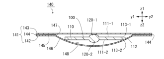
図1は、第1の実施形態に係る錠剤入り包装体140の底面図(すなわち、z2側からz1側を見た図)である。図2は、図1に示す2-2線における錠剤入り包装体140の切断面図(断面以外は省略)である。錠剤入り包装体140は、薄型錠剤100と、薄型錠剤100を包装する包装体141とを含む。本実施形態の包装体は、剥離カバー式のブリスター包装体とも呼ばれる。
(First embodiment)
FIG. 1 is a bottom view (that is, a view from the z2 side to the z1 side) of the tablet-containing
(薄型錠剤)
図3は、第1の実施形態の薄型錠剤100の斜視図である。図4は、薄型錠剤100の底面図である。図5は、薄型錠剤100の正面図である。図5に示すように、薄型錠剤100は、薄い円柱形の本体110を含み、さらに、ともに本体110から突出した第1の突起120-1と第2の突起120-2と(以下、区別せずに突起120と呼ぶ場合がある)を含む。
(thin tablet)
FIG. 3 is a perspective view of the
(本体)
図3に示すように、本体110は、z方向に平行な中心軸をもつ薄い円柱である。図5に示すように、本体110は、第1の表面111-1と第2の表面111-2と側面112とを含む。第1の表面111-1と第2の表面111-2と(以下、区別せずに表面111と呼ぶ場合がある)は同一形状であり、z方向に相互に平行移動した形状をもつ。第1の表面111-1は、z1方向を向き、xy平面に平行な円であり(図4)、第1の外縁113-1に囲まれる(図4)。第2の表面111-2は、z2方向を向き、xy平面に平行な円であり、第2の外縁113-2に囲まれる。以下、第1の外縁113-1と第2の外縁113-2とを区別せずに外縁113と呼ぶ場合がある。
(Body)
As shown in FIG. 3,
図3に示すように、側面112は、第1の外縁113-1と第2の外縁113-2とを2つの表面111の法線方向(z方向)に接続する円筒形である。表面111と側面112との間の角度134は、90度である。表面111と側面112との間の角度134は、薄型錠剤100内において、外縁113の仮想接線131に直交して表面111に沿う第1の仮想線132と、外縁113の仮想接線131に直交して側面112に沿う第2の仮想線133とのなす角度134である。言い換えると、回転対称な本体110において、表面111に対する側面112の角度134は、回転の中心を通る平面で切断したときに、表面111と側面112とがなす角度134と表現される。
As shown in FIG. 3, the
本実施形態の本体110の厚さは0.8mmである。他の例において、本体110の厚さは、例えば0.5mm以上、1.5mm以下である。他の例において、本体110の厚さは、例えば0.5mm以上、1.2mm以下である。本体110の厚さは表面111に直交するz方向に平行に規定される。一例において、薄型錠剤100の重さは200mgであり、厚さは約1.1mmである。一例において、薄型錠剤100の重さは250mgであり、厚さは約1.3mmである。
The thickness of the
本実施形態の本体110の最大幅、すなわち直径は14mmである。他の例において、表面111の最大幅は、14mmを上回る。表面111の幅は、本体110の厚さに直交する方向に規定される。
The maximum width, or diameter, of the
本体110は、例えば真平錠、隅丸平錠、隅角平錠などと呼ばれる錠剤の形態を使用可能である。
For the
(突起)
図5に示すように、突起120は、2つ表面111の各々に設けられる。第1の表面111-1からz1方向に第1の突起120-1が突出している。第2の表面111-2からz2方向に第2の突起120-2が突出している。第2の表面111-2に対する第2の突起120-2の位置及び形状と、第1の表面111-1に対する第1の突起120-1の位置及び形状とは、相互に、xy平面に平行な仮想中心面に対して鏡面対称である。
(protrude)
As shown in FIG. 5, protrusions 120 are provided on each of the two surfaces 111 . A first protrusion 120-1 protrudes in the z1 direction from the first surface 111-1. A second protrusion 120-2 protrudes in the z2 direction from the second surface 111-2. The position and shape of the second protrusion 120-2 with respect to the second surface 111-2 and the position and shape of the first protrusion 120-1 with respect to the first surface 111-1 are mutually parallel to the xy plane. mirror symmetry with respect to a virtual central plane.
図3に示すように、突起120は、凸状の滑らかな表面をもつ。図4に示すように、突起120は、本体110と同じ仮想軸を中心とする回転体である。結果として、薄型錠剤100も、本体110及び突起120と同じ仮想軸を中心とする回転体である。突起120と本体110とは一体的に形成されている。突起120と本体110との境界は円形である。z方向から見たとき、突起120の全体が、突起120と本体110との境界の外形より外に出ない。xy平面に平行な突起120の断面は、表面111からz方向に離れるにつれて小さくなる。
As shown in FIG. 3, protrusion 120 has a convex smooth surface. As shown in FIG. 4, the projection 120 is a body of rotation about the same imaginary axis as the
図4に示すように、表面111の面積のうち突起120が占める割合は5%である。すなわち、表面111のうち、平面である部分が必ず外部に露出している。表面111の面積のうち突起120が占める割合は、90%以下であることが好ましい。表面111からの突起120の高さが、本体110の厚さの100%以下であることが好ましい。本実施形態では、表面111からの突起120の高さは、本体110の厚さの100%である。本実施形態の突起120は、概ね球の一部を切り出した形状であり、直径に直交する平面で球を6:1に切断して得られる小さい部分である。
As shown in FIG. 4, the proportion of the area of the surface 111 occupied by the protrusions 120 is 5%. That is, the planar portion of the surface 111 is always exposed to the outside. The proportion of the area of the surface 111 occupied by the protrusions 120 is preferably 90% or less. The height of protrusion 120 from surface 111 is preferably 100% or less of the thickness of
突起120は、表面111の法線方向すなわちz方向において本体110の重心に重なる位置に形成されている。すなわち、突起120と表面111との境界を規定する円の中心は、表面111を規定する円の中心に一致する。
The protrusion 120 is formed at a position overlapping the center of gravity of the
(隙間)
図6は、薄型錠剤100を無限に広がる仮想的な外部平面130上に配置した例示的な状態における正面図である。第1の表面111-1が外部平面130に向いている。第1の突起120-1が外部平面130に接触した状態で、第1の突起120-1が設けられた第1の表面111-1を囲む第1の外縁113-1の少なくとも一部と外部平面130との間に、0.1mm以上の隙間135が形成される。隙間135が、0.1mm以上となるように突起120を形成することが好ましい。重力下において薄型錠剤100を仮想的な外部平面130上に配置したとき、外力を加えなくても0.1mm以上の隙間135が形成されるように突起120を形成することが好ましい。
(gap)
FIG. 6 is a front view of an exemplary state in which the
図6では、第1の外縁113-1の左側が外部平面130に接触している状態が示される。第1の外縁113-1は円形であり、さらに、図5のz方向において突起120が本体110の重心に重なるので、重力下では第1の外縁113-1のうちのどの部分が外部平面130に接触するかは限定されない。なお、薄型錠剤100が実際に配置される場所は、完全な平面に限定されるわけではない。
In FIG. 6, the left side of first outer edge 113-1 is shown in contact with
(口腔内崩壊錠剤)
薄型錠剤100は、一例において口腔内崩壊錠剤である。薄型錠剤100の水中崩壊時間は、一例において約7秒以下、好ましくは5秒以下である。薄型錠剤100の口腔内崩壊時間は、一例において6秒以下、好ましくは5秒以下である。
(orally disintegrating tablet)
薄型錠剤100に含まれる薬効成分は、医薬用成分や食品・健康食品における栄養成分である。薬効成分は、薬効成分単独、又は薬効成分を徐放化若しくは苦味マスキングなどの目的でコーティング又は造粒をおこなったものを添加することができる。薄型錠剤100に含まれる薬効成分の用途・種類等に特に制限はない。
The medicinal ingredients contained in the
薄型錠剤100は、薬効成分に加えて、必要に応じて、賦形剤、界面活性剤、滑沢剤、酸味料、甘味料、矯味剤、香料、着色剤、安定化剤など医薬上許容されるその他の任意の成分を含むことができる。これら任意成分として、例えば、医薬品添加物辞典(薬事日報社)、日本薬局方に記載の該当成分を用いることができる。また、本発明の所望の効果が奏される限り、各成分の配合割合に特に制限はなく、当業者が適宜決めることができる。
The
上記の薄型錠剤100の材料は、崩壊性粒子組成物に薬効成分(又は、該薬効成分を含む医薬組成物)及びその他の上記の任意成分を混合して得られた混合物である。薄型錠剤100の製造装置は、型の形状を除いて、当業者に知られた適当な打錠機である。薄型錠剤100は例えば、打錠圧縮力約2~20kN、好ましくは約5~20kNで打錠する。ステアリン酸マグネシウムのような滑沢剤を予め打錠機の型(臼・杵とも呼ばれる)に噴霧又は塗布して滑沢する、「外部滑沢打錠法」と呼ばれる方法を用いることもできる。
The material of the
崩壊性粒子組成物には崩壊剤成分として、例えば酸型カルボキシメチルセルロースが含まれる。崩壊性粒子組成物には、例えば、崩壊力、結合力及び錠剤の服用感等の諸特性を調整する目的で、当業者に公知の各種の任意成分を適宜、添加混合しても良い。このような成分の例として、流動化剤、甘味剤、香料及び、着色料等を挙げることが出来る。 The disintegrating particle composition contains, for example, acid-type carboxymethylcellulose as a disintegrant component. Various optional ingredients known to those skilled in the art may be appropriately added and mixed to the disintegrating particle composition for the purpose of adjusting various properties such as disintegrating force, binding force, and tablet ingestion feeling. Examples of such ingredients include fluidizing agents, sweetening agents, flavoring agents, coloring agents, and the like.
崩壊性粒子組成物における各成分の配合量は各成分の種類、崩壊性粒子組成物の使用対象である薬効成分の種類及び用途、最終製品である口腔内崩壊錠剤の用途等に応じて、当業者が適宜決めることが出来る。 The amount of each component in the disintegrating particle composition should be determined according to the type of each component, the type and application of the medicinal ingredient for which the disintegrating particle composition is to be used, and the intended use of the final product, the orally disintegrating tablet. The operator can decide accordingly.
(易服用性固形製剤)
薄型錠剤100は、口腔内崩壊錠剤であることに加えて、又は口腔内崩壊錠剤であることに代えて易服用性固形製剤である。「易服用性」とは、一般に、固形製剤等の性質・特性として、飲み易い(嚥下が容易である)ことを意味する。一例において、薄型錠剤100は、水に触れると滑り性を示すゲル化剤を含む。
(Easy-to-take solid preparation)
The
(薄型錠剤の変形例)
他の例において、表面と側面との間の角度は、90度未満である。そのような他の例において、例えば、第2の表面は第1の表面と同心であり、さらに、第2の表面が第1の表面より半径の小さな円である。すなわち、円錐台形である。
(Modified example of thin tablet)
In other examples, the angle between the surface and the side is less than 90 degrees. In such other examples, for example, the second surface is concentric with the first surface, and the second surface is a circle with a smaller radius than the first surface. That is, it has a truncated cone shape.
(包装体)
図2に示すように、包装体141は、収容部材142とカバー143と接着層144とを含む。
(package)
As shown in FIG. 2,
収容部材142は、薄いシート材を加工して形成される。収容部材142は、xy平面に平行に広がる余白部145と、余白部145からz2方向に窪んだ収容部146とを含む。収容部146は、薄型錠剤100を滑らせるための滑動面148を収容部146の内部に含む。
The
収容部材142は、外縁において余白部145と収容部146との境界を規定する入口147を含む。入口147は、z1方向に開放されている。収容部146は、入口147からz2方向に窪んでいる。図1に示すように、入口147は円形である。余白部145は収容部146の外部において入口147から広がる。
Receiving
図7は、図2と同一の断面における滑動面148の切断面図(断面以外は省略)である。入口147は、xy平面に平行な仮想的な平面150に平行に広がる。滑動面148は、仮想的な平面150に直交するz方向において収容部146の他の部分と重ならない。すなわち、カバー143(図2)がない状態において、z1方向からz2方向を見たとき、滑動面148の全体が入口147から見える。滑動面148は、仮想的な平面150に対して傾斜している。
FIG. 7 is a cross-sectional view of the sliding
滑動面148は、仮想的な平面150に直交する仮想的な中心軸151の周りで回転対称である。仮想的な中心軸151は、入口147の中心を通る。滑動面148が、入口147から収容部146内部において仮想的な中心軸151に交わる位置まで連続的に広がる。一例において、滑動面148は、1つの球面を仮想的な平面150で切断して得られる形状をとる。
The sliding
仮想的な平面150に対する滑動面148の傾斜角度は、いずれの位置でも0度以上、70度以下である。滑動面148のうちの入口147に最も近い領域における傾斜角度は、0度より大きい。薄型錠剤100にz方向に直交する方向の力を加えて滑らせやすいという理由から、傾斜角度は、0度以上、45度以下であることが好ましく、0度以上、30度以下であることがより好ましい。仮想的な平面150に対する滑動面148の傾斜角度は、入口147から離れるにつれて小さくなる。傾斜角度は、入口147から離れるにつれてなだらかに変化する。例えば、図7の切断面内において点P2は点P1より入口147から遠い。点P2における傾斜角度A2は、点P1における傾斜角度A1より小さい。
The inclination angle of the sliding
図2のカバー143は、xy平面に平行な連続した1枚のシート材で形成されており、収容部材142のz1側に位置する。カバー143は、概ね入口147の全体をたるみ無く覆うとともに、余白部145を覆う。z方向における余白部145とカバー143との間には、xy平面に平行に広がる接着層144が挟まれている。接着層144は、カバー143を剥離可能に余白部145に接着する。カバー143は、外縁の一部に持ち手部149を含む。持ち手部149と余白部145との間には接着層144が存在しない。
The
図2に示すように、収容部146内において、薄型錠剤100の第2の表面111-2が滑動面148に向いており、第1の表面111-1が、カバー143に向いている。薄型錠剤100は、一つの状態において、表面111がxy平面に平行である。なお、薄型錠剤100は、収容部146内において、図2に示す状態からわずかに動いてもよい。図2に示す状態において、第2の外縁113-2は、滑動面148上に接触している。第1の表面111-1に設けられた第1の突起120-1は、カバー143に向いている。第1の突起120-1のz1側端部は、カバー143に接触している。
As shown in FIG. 2, the second surface 111-2 of the
(使用方法)
図8は、図2と同じ断面における収容部材142と動かされた薄型錠剤100との切断面図である。図8では、薄型錠剤100が部分的に入口147から外に出ている点で図2と異なる。
(how to use)
FIG. 8 is a cross-sectional view of the containing
図2に示すように、まず、使用者は、概ね収容部材142を下にして、カバー143を上にした状態で錠剤入り包装体140を持つ。次に、使用者は、持ち手部149(図1)でカバー143を収容部材142から剥離して、薄型錠剤100を外部に露出する。次に、使用者は、入口147を通して、指を入れて薄型錠剤100の第1の表面111-1と第1の突起120-1との少なくとも一方に触れる。次に、使用者は、指で薄型錠剤100に対してz2方向の力を加えるとともに、薄型錠剤100に対してy2方向の力を加える。
As shown in FIG. 2, first, the user holds the tablet-containing
その結果、図8に示すように、薄型錠剤100が部分的に入口147から外に出る。次に、使用者は、第1の表面111-1と第2の表面111-2とをつまんで、薄型錠剤100を完全に取り出す。このように、収容部材142は、入口147から挿入された物体としての指による力が、収容部146に収容された薄型錠剤100の一部に印加されたとき(すなわち力印加時)に、収容部146に収容された薄型錠剤100の少なくとも一部が入口147に向かって動く構造をもつ。より具体的には、力印加時に、収容部146に収容された薄型錠剤100の他の一部が入口147から突出する。
As a result, the
(製造方法)
図9は、錠剤入り包装体140の製造方法を示すフロー図である。まず、図9のステップ161において、図2に示すような収容部材142を、例えば真空成型により作成する。次に、図9のステップ162において、図2に示すような状態で収容部146に薄型錠剤100を収容する。図9のステップ163において、図2に示すように、接着層144により収容部材142とカバー143とを剥離可能に接着する。
(Production method)
FIG. 9 is a flowchart showing a method for manufacturing the tablet-containing
図10及び図11は、真空成型による収容部材142の作成方法を説明する製造装置101及びシート材168の切断面図(断面以外は省略)である。図10は成型前、図11は成型後の状態を示す。製造装置101は、型164と成型装置102とを含む。製造のとき、図10に示すような型164が用意される。なお、型164と凹凸が逆の型が使用されてもよい。
10 and 11 are cross-sectional views (omitted except for the cross section) of the
型164は、余白部145(図2)を成型するための平面状の第1の成型面165と、収容部146(図2)を成型するための曲面状の第2の成型面166とを含む。第2の成型面166は、第1の成型面165に囲まれている。凹凸が逆である点を除いて、第1の成型面165及び第2の成型面166の形状は、余白部145(図2)の表面及び滑動面148(図2)の形状に概ね一致する。型164には、第1の成型面165又は第2の成型面166に複数の吸引孔167が設けられている。吸引孔167は別の箇所に設けられていてもよい。
The
まず、収容部材142(図2)の材料となるシート材168を加熱する。次に、第1の成型面165及び第2の成型面166にシート材168を近づける。次に、吸引装置である成型装置102により、複数の吸引孔167を介して吸引を行うことにより、第1の成型面165及び第2の成型面166とシート材168との間が真空状態となる。その結果、図11に示すように、第1の成型面165及び第2の成型面166に沿ってシート材168が成型される。
First, the
(材料)
収容部材142を形成するためのシート材168(図10)の材料として、例えば熱可塑性樹脂、アルミニウムが挙げられる。シート材168に使用される熱可塑性樹脂として、例えばポリ塩化ビニル、ポリ塩化ビニリデン、ポリクロロトリフルオロエチレン、ポリスチレン、ポリアミド、ポリイミド、ポリウレタン、ナイロン、石油樹脂;ポリエチレンテレフタレート(PET)、ポリブチレンテレフタレート(PBT)等のポリエステル;ポリテトラフルオロエチレン、ポリフッ化ビニル、ポリフッ化ビニリデン、エチレン・四フッ化エチレン共重合体などのフッ素化樹脂共重合体;ABS樹脂(アクリロニトリル・ブタジエン・スチレン)、AS樹脂(アクリロニトリル・スチレン)、PMMA樹脂等のアクリル樹脂;ポリエチレン、ポリプロピレン、環状オレフィンポリマー、環状オレフィンコポリマー(COP)等のポリオレフィンが挙げられる。シート材168は、上記の熱可塑性樹脂のうちの1つにより形成されてもよく、上記の熱可塑性樹脂から選択される2つ以上の熱可塑性樹脂を積層して形成されてもよい。シート材168は、上記の熱可塑性樹脂に無機酸化物(酸化ケイ素、酸化チタン、酸化アルミニウム)、及び金属のうちの1つ以上を蒸着して形成されてもよい。シート材168にアルミニウムを使用する場合、アルミニウムに上記の熱可塑性樹脂が積層されてもよく、アルミニウムが上記の熱可塑性樹脂により被覆されてもよい。シート材168の形成に使用される積層方法として、例えばドライラミネート方法、押出ラミネート方法、ホットメルトラミネート方法、ウエットラミネート方法、サーマル(熱)ラミネート方法が挙げられる。
(material)
Examples of materials for the sheet material 168 (FIG. 10) for forming the
カバー143として、例えば、収容部材142を形成するための上記の材料が挙げられる。
Cover 143 includes, for example, the materials described above for forming
接着層144の材料として、例えば樹脂が挙げられる。接着層144を形成する樹脂は、必要に応じて酸化防止剤を含有する。接着層144を形成するための樹脂として、例えばポリオレフィン、エチレン-メタクリレート-グリシジルアクリレート三元共重合体;各種ポリオレフィンに一塩基性不飽和脂肪酸、二塩基性不飽和脂肪酸、又はこれらの無水物をグラフトさせたもの(マレイン酸グラフト化エチレン-酢酸ビニル共重合体、マレイン酸グラフト化エチレン-α-オレフィン共重合体など)が挙げられる。一塩基性不飽和脂肪酸として、アクリル酸、メタクリル酸などが挙げられる。二塩基性不飽和脂肪酸として、マレイン酸、フマル酸、イタコン酸などが挙げられる。酸化防止剤として、公知の酸化防止剤、例えば、ヒンダードフェノール系酸化防止剤、リン系酸化防止剤、チオエーテル系酸化防止剤などが挙げられる。接着層144の厚みは、特に限定されないが、3μm以上、50μm以下が好ましく、5μm以上、30μm以下が好ましい。
Examples of the material of the
一例において、アルミニウムにポリプロピレンをコートした材料から収容部材142が形成され、カバー143としてポリオレフィンが使用され、収容部材142とカバー143とが接着層144を介して熱硬化(ヒートシール)される。本明細書に記載の他の実施形態においても、型の形状を除いて同様の材料と同様の製造装置が使用されて、同様の製造方法により錠剤入り包装体が製造される。
In one example, the
(包装部材の変形例)
他の例において、滑動面148と入口147との間に、滑動面148ではない領域が含まれる。なお、薄型錠剤100を滑動面148から入口147を通って滑らかに外部に移動させるために、滑動面148と入口147とが連続しているほうが好ましい。他の例において、仮想的な平面150に対する滑動面148の傾斜角度は、一定であってもよい。 他の例において、カバー143は、入口147を少なくとも部分的に覆う。すなわち、カバー143は、入口147の全体を覆うか又は一部を覆う。
(Modified example of packaging member)
In another example, an area that is not the sliding
(薄型錠剤の変形例)
薄型錠剤100は図5に示す突起120を含まないものであってもよく、突起120は1つでもよく、3つ以上でもよい。突起120の位置は図5に示す位置と異なる位置であってもよい。例えば突起120が本体110の重心に重ならない場合、突起120を中心として本体110が回転せず、本体110が安定しやすい。突起120は、円柱形、多角形の角柱その他の柱体であってもよい。本体110から遠い突起120の先端が平面であってもよい。突起120はz方向から見たときに文字を描くように形成されてもよい。突起120は、円錐、角錐その他の錐体であってもよい。多角形の柱体及び錐体は角が丸みを帯びていてもよい。z方向から見た突起120の外形は、花の形、魚の形など複雑な形状であってもよい。
(Modified example of thin tablet)
The
z方向から見たとき本体110の外縁113と突起120の外形は異なっていてもよい。z方向から見たとき外縁113は多角形であってもよい。多角形の外縁113の角は丸められていてもよい。外縁113は他の形状でもよい。外縁113の形状は、花の形、魚の形など複雑な形状であってもよい。本体110は、円錐台形、角錐台形その他の錐台形であってもよい。
The outer edge 113 of the
(まとめ1)
本実施形態によれば、指などの物体で薄型錠剤100の一部に力を印加することにより、薄型錠剤100の少なくとも一部が入口147に向かって動くので、薄型錠剤100を包装体141から取り出しやすい。
(Summary 1)
According to this embodiment, applying a force to a portion of
本実施形態によれば、指などの物体で薄型錠剤100の一部に力を印加することにより、薄型錠剤100の他の一部が入口147から突出するので、薄型錠剤100を包装体141から取り出しやすい。
According to this embodiment, by applying force to a part of the
本実施形態によれば、滑動面148が、仮想的な平面150に直交する方向において収容部146の他の部分と重ならず、さらに、滑動面148が、仮想的な平面150に対して傾斜しているので、滑動面148に沿って薄型錠剤100を移動させることで、薄型錠剤100の他の一部を入口147から簡単に突出させることができる。
According to this embodiment, the sliding
本実施形態によれば、仮想的な平面150に対する滑動面148の傾斜角度が、0度以上、70度以下であり、滑動面148のうちの入口147に最も近い領域における傾斜角度が0度より大きいので、仮想的な平面150に平行な方向に薄型錠剤100に力を加えやすく、薄型錠剤100の他の一部を入口147から簡単に突出させることができる。
According to this embodiment, the inclination angle of the sliding
本実施形態によれば、仮想的な平面150に対する滑動面148の傾斜角度が、入口147から離れるにつれて小さくなるので、仮想的な平面150に直交する方向の動きを減らすと同時に、仮想的な平面150に平行な方向の動きを増やすことで、薄型錠剤100を滑らかに動かすことができる。
According to this embodiment, the angle of inclination of the sliding
本実施形態によれば、入口147を少なくとも部分的に覆うカバー143を含むので、薄型錠剤100を安定して収容部146内に収容することができる。
According to this embodiment, since the
本実施形態によれば、包装体141が、カバー143を剥離可能に余白部145に接着する接着層144を含むので、カバー143を破って開ける必要がなく、薄型錠剤100を壊れにくくすることができる。
According to this embodiment, since the
本実施形態によれば、第2の表面111-2の外縁113が滑動面148上に接触した状態で薄型錠剤100が収容部146内に位置するとき、第1の表面111-1に設けられた突起120がカバー143に向くので、突起120がない場合に比べて薄型錠剤100が収容部146内で動きにくくなり、薄型錠剤100が損傷しにくい。さらに、突起120がカバー143に向くので、本体110を厚くしなくても薄型錠剤100の揺れを制限することができ、薄型錠剤100を損傷しにくくすることができる。
According to this embodiment, when the
本実施形態によれば、入口147が、仮想的な平面150に平行な円であり、滑動面148が、仮想的な平面150に直交する仮想的な中心軸151の周りで回転対称であるので、薄型錠剤100をどの方向に動かしても薄型錠剤100が損傷しにくい。さらに、仮想的な中心軸151が、入口147の中心を通り、滑動面148が、入口147から収容部146内部において仮想的な中心軸151に交わる位置まで連続的に広がるので、滑動面148が仮想的な中心軸151に交わる位置まで薄型錠剤100を滑らかに動かしやすい。
Since according to this embodiment the
(まとめ2)
本実施形態によれば、表面111に突起120が設けられているので、薄型錠剤100が外部平面130(例えば床)上に置かれたときに、表面111の外縁113と外部平面130との間に隙間135ができ、薄型錠剤100を取りやすい。
(Summary 2)
According to this embodiment, the surface 111 is provided with a protrusion 120 so that when the
本実施形態によれば、表面111と側面112とのなす角が90度以下である場合は、突起120がなければ特に取りにくいが、突起120のおかげで、表面111の外縁113と外部平面130との間に隙間135ができ、薄型錠剤100を取りやすい。
According to this embodiment, if the angle formed by the surface 111 and the
本実施形態によれば、本体110の厚さが0.5mm以上、1.5mm以下である、又は0.5mm以上、1.2mm以下であるためにつまみ難い薄型錠剤100において、表面111と外部平面130との間に隙間135をつくり、薄型錠剤100を取りやすくすることができる。
According to this embodiment, the thickness of the
本実施形態によれば、表面111の最大幅が14mm以上であるためにつまみ難い薄型錠剤100において、表面111と外部平面130との間に隙間135ができるので、薄型錠剤100を取りやすい。
According to this embodiment, the
本実施形態によれば、表面111の面積のうち突起120が占める割合が90%以下であるので、突起120によって必要以上に薄型錠剤100が厚くなることを防ぎながら、薄型錠剤100を取りやすくすることができる。
According to the present embodiment, the projections 120 account for 90% or less of the area of the surface 111. Therefore, the projections 120 prevent the
本実施形態によれば、表面111からの突起120の高さが、本体110の厚さの100%以下であるので、突起120によって必要以上に薄型錠剤100が厚くなることを防ぎながら、薄型錠剤100を取りやすくすることができる。
According to this embodiment, since the height of the protrusions 120 from the surface 111 is 100% or less of the thickness of the
本実施形態によれば、外縁113の少なくとも一部と外部平面130との間に0.1mm以上の隙間135が形成されるので、薄型錠剤100を人の指で取りやすい。
According to this embodiment, a
本実施形態によれば、突起120が本体110の重心に重なるので、突起120を中心として本体110を様々な向きに傾けやすい。
According to this embodiment, since the protrusion 120 overlaps the center of gravity of the
本実施形態によれば、2つの表面111の各々に突起120があるので、いずれの表面111が外部平面130に面したときでも、表面111と外部平面130との間に隙間135ができ、薄型錠剤100を取りやすい。
According to this embodiment, since each of the two surfaces 111 has a protrusion 120, when either surface 111 faces the
本実施形態によれば、薄型錠剤100が口腔内崩壊錠剤と易服用性固形製剤との少なくとも一方である場合に、隙間135の存在によってすばやく取り出すこと、及び拾うことが可能であるので、拾っているときに崩壊すること、及びゲル化することを防ぎやすい。
According to this embodiment, when the
本実施形態によれば、突起120により、薄型錠剤100を包装体141内で動きにくくすることと、薄型錠剤100を拾いやすくすることとの両方が実現されるので、別々の機構を設ける場合に比べて構造が簡単となる。
According to this embodiment, the protrusion 120 makes it difficult to move the
(第2の実施形態)
図12は、第2の実施形態の錠剤入り包装体240の切断面図である。図12の切断面は、第1の実施形態における図2の切断面と同じ位置である。本実施形態の錠剤入り包装体240は、図2に示す接着層144を含まない。すなわち、本実施形態では、収容部材242とカバー243とがz方向に接着されていない。
(Second embodiment)
FIG. 12 is a cross-sectional view of a tablet-containing
収容部材242は、第1の返し252-1と第2の返し252-2と(以下、区別せずに返し252と呼ぶ場合がある)を含む。第1の返し252-1は、余白部245のy1側端縁からz1方向に延びた後、y2方向に延びる。カバー243は、余白部245と第1の返し252-1とに挟まれているので、z方向に実質的に(少なくとも、入口247から薄型錠剤200が出る程には)動かない。また、カバー243は、第1の返し252-1に阻まれているので、y1方向に実質的に動かない。第2の返し252-2は、余白部245のy2側端縁からz1方向に延びた後、y1方向に延びる。カバー243は、余白部245と第2の返し252-2とに挟まれているので、z方向に実質的に動かない。また、カバー243は、第2の返し252-2に阻まれているので、y2方向に実質的に動かない。
The
カバー243は、返し252に沿ってx方向にのみ動く。開封時には、使用者がカバー243をx方向にずらすことにより、カバー243と収容部材242とが分離する。その結果、薄型錠剤200が外部に露出する。他の例において、カバー243は、他の構造により、入口247を開閉可能であるように収容部材242に対してスライド可能であってもよい。
Cover 243 moves along barb 252 only in the x-direction. At the time of opening, the
本実施形態によれば、カバー243をスライドさせるだけで薄型錠剤200が外部に露出するので、薄型錠剤200でカバー243を破る場合に比べて、薄型錠剤200が壊れにくい。
According to this embodiment, the
(第3の実施形態)
図13は、第3の実施形態の錠剤入り包装体340の底面図(すなわち、z2側からz1側を見た図)である。図14は、図13の14-14線における錠剤入り包装体340の切断面図である。図14の切断面は、第1の実施形態における図2の切断面と同じ位置である。包装体341は、収容部材342とカバー343と接着層344とを含む。
(Third Embodiment)
FIG. 13 is a bottom view (that is, a view of the z1 side from the z2 side) of the tablet-containing
収容部材342は、薄いシート材を加工して形成される。図14に示すように、収容部材342は、xy平面に平行に広がる余白部345と、余白部345からz2方向に窪んだ収容部346とを含む。収容部346は、薄型錠剤300を滑らせるための滑動面348を収容部346の内部に含む。
The
収容部材342は、外縁において余白部345と収容部346との境界を規定する入口347を含む。入口347は、z1方向に開放されている。収容部346は、入口347からz2方向に窪んでいる。図13に示すように、入口347は長方形である。余白部345は収容部346の外部において入口347から広がる。
Receiving
収容部346は、入口347の外縁から滑動面348の外縁までz2方向に延びる筒状の壁部353を含む。入口347は、xy平面に平行に(すなわち、図7と同様の仮想的な平面に平行に)広がる。滑動面348は、xy平面に直交するz方向において収容部346の他の部分と重ならない。すなわち、カバー343がない状態において、z1側からz2側を見たとき、滑動面348の全体が入口347から見える。
The
滑動面348は、xy平面に対して傾斜した平面である。すなわち、xy平面に対する滑動面348の傾斜角度は一定である。傾斜角度は、0度より大きく、30度以下である。z方向において、滑動面348のy1側端縁と入口347との距離は、滑動面348のy2側端縁と入口347との距離より大きい。滑動面348は、図14と同じ断面でx方向に平行に延びている。
The sliding
カバー343は、xy平面に平行な連続した1枚のシート材で形成されており、収容部材342のz1側に位置する。カバー343は、概ね入口347の全体をたるみ無く覆うとともに、余白部345を覆う。z方向における余白部345とカバー343との間には、xy平面に平行に広がる接着層344が挟まれている。接着層344は、カバー343を剥離可能に余白部345に接着する。カバー343は、外縁の一部に持ち手部349を含む。持ち手部349と余白部345との間には接着層344が存在しない。
The
図14に示すように、収容部346内において、薄型錠剤300の第2の表面311-2が滑動面348に向いており、第1の表面311-1が、カバー343に向いている。薄型錠剤300は、一つの状態において、表面311がxy平面に平行である。なお、薄型錠剤300は、収容部346内において、図14に示す状態からわずかに動いてもよい。図14に示す状態において、第2の突起320-2のz2側端部付近と、第2の外縁313-2のy2側端部とが、滑動面348上に接触している。第1の表面311-1に設けられた第1の突起320-1は、カバー343に向いている。第1の突起320-1のz1側端部は、カバー343に接触している。薄型錠剤300のy1側端部において、側面312が壁部353に触れている。
As shown in FIG. 14, the second surface 311-2 of the
(使用方法)
図14において、使用者は、カバー343を収容部材342から剥離した後、入口347を通して、指を入れて薄型錠剤300の第1の表面311-1と第1の突起320-1との少なくとも一方に触れる。次に、使用者は、第1の突起320-1のy1側(すなわち、入口347と滑動面348とがz方向において比較的離れている空間に位置する部分)に位置する第1の表面311-1をz2側に押すことにより、第2の突起320-2を支点として薄型錠剤300のy2側(すなわち、入口347と滑動面348とがz方向において比較的近い空間に位置する部分)がz1方向に動く。その動きにより、薄型錠剤300が部分的に入口347に近づくか、又は、入口347から外に出る。次に、使用者が、薄型錠剤300に対してy2方向の力を加えると、薄型錠剤300が滑動面348上を滑り、薄型錠剤300が入口347から外に出るか、又は、さらに入口347から外に出る。
(how to use)
In FIG. 14, after peeling off the
本実施形態によれば、滑動面348の傾斜角度が一定なので、薄型錠剤100を一定の力で滑らかに動かすことができる。
According to this embodiment, since the inclination angle of the
(第4の実施形態)
図15は、第4の実施形態の錠剤入り包装体440の切断面図である。図15の切断面は、第3の実施形態における図14の切断面と同じ位置である。第4の実施形態の錠剤入り包装体440は、第3の実施形態の錠剤入り包装体340と同様の形状をもつが、滑動面448のy2側端縁が、入口447に重なるという点が異なる。すなわち、滑動面448は、y2側端縁において入口447から段差無くなだらかに続いている。
(Fourth embodiment)
FIG. 15 is a cross-sectional view of a tablet-containing
本実施形態によれば、薄型錠剤400が滑動面448に沿ってy2方向に動くとき、薄型錠剤400が壁部453にぶつからずに滑らかに入口447から出る。従って、薄型錠剤400が取り出し時に壊れにくい。また、第2の突起420-2が無い他の例でも、薄型錠剤400を入口447から外に出しやすい。
According to this embodiment, when the
(第5の実施形態)
図16は、第5の実施形態に係る錠剤入り包装体540の底面図である。図17は、図16に示す17-17線における錠剤入り包装体540の切断面図(断面以外は省略)である。錠剤入り包装体540は、薄型錠剤500と、薄型錠剤500を包装する包装体541とを含む。本実施形態の薄型錠剤500は、第1の実施形態の薄型錠剤100と同様の形状をもつ。
(Fifth embodiment)
FIG. 16 is a bottom view of a tablet-containing
(包装体)
図17に示すように、包装体541は、収容部材542とカバー543と接着層544とを含む。図18は、収容部材542の平面図(すなわち、z1側からz2側を見た図)である。
(package)
As shown in FIG. 17,
図17に示すように、収容部材542は、薄いシート材を加工して形成される。収容部材542は、xy平面に平行に広がる余白部545と、余白部545からz2方向に窪んだ収容部546とを含む。収容部材542は、外縁において余白部545と収容部546との境界を規定する入口547を含む。入口547は、z1方向に開放されている。収容部546は、入口547からz2方向に窪んでいる。図18に示すように、入口547は円形である。余白部545は収容部546の外部において入口547から広がる。
As shown in FIG. 17, the
図17に示すように、収容部546は、収容部546の内部に、薄型錠剤500を載置することに適した載置台570と、入口547から遠ざかる方向に向かって窪んだ溝571とを含む。
As shown in FIG. 17, the
載置台570は、入口547に向いた対向面572と、対向面572から窪んだ受容穴573とを含む。対向面572は、xy平面に平行で、z1方向を向き(図17)、円形の外縁574と円形の内縁575との間に広がる(図18)。図17に示すように、対向面572は、入口547からz2方向に離れている。受容穴573は、対向面572の内縁575からz2方向に、すなわち、入口147から遠ざかる方向に向けて窪んでいる。
The mounting table 570 includes a facing
xy平面に平行な対向面572の内縁575の径は、xy平面に平行な第2の突起520-2の最大径(すなわち、第2の表面511-2との境界の径)より小さい。第2の突起520-2の一部が受容穴573内に入った状態で、対向面572の内縁575が第2の突起520-2に接し、受容穴573の内面は第2の突起520-2から離間する。
The diameter of the
図17に示すように溝571は、内壁576と外壁577と底壁578とを含む。内壁576は、対向面572の外縁574からz2方向に延びた円筒状である。外壁577は、入口147の外縁からz2方向に延びた円筒状である。底壁578は、内壁576のz2側端部と外壁577のz2側端部との間で、xy平面に平行に広がる。図18に示すように溝571は、対向面572の外縁574の全体から窪んでいる。
As shown in FIG. 17,
図17に示すように入口547は、仮想的な平面(すなわち、xy平面に平行な平面)に平行に広がる。対向面572及び底壁578の内面は、xy平面に直交するz方向において収容部546の他の部分と重ならない。すなわち、カバー543がない状態において、z1方向からz2方向を見たとき、対向面572及び底壁578の内面の全体が入口547から見える。載置台570及び溝571は、xy平面に直交する仮想的な中心軸551の周りで回転対称である。仮想的な中心軸551は、入口547、対向面572の内縁575、及び対向面572の外縁574の中心を通る。
As shown in FIG. 17,
カバー543は、xy平面に平行な連続した1枚のシート材で形成されており、収容部材542のz1側に位置する。カバー543は、概ね入口547の全体をたるみ無く覆うとともに、余白部545を覆う。z方向における余白部545とカバー543との間には、xy平面に平行に広がる接着層544が挟まれている。接着層544は、カバー543を剥離可能に余白部545に接着する。カバー543は、外縁の一部に持ち手部549を含む。持ち手部549と余白部545との間には接着層544が存在しない。
The
(載置状態)
図17に示すような、薄型錠剤500が載置台570に載置された載置状態について説明する。第1の表面511-1はカバー543に向く。第2の表面511-2は載置台570に向く。薄型錠剤500は、一つの状態において、表面511がxy平面に平行である。第2の突起520-2の一部が受容穴573に受容されて、x方向及びy方向の動きが制限される。
(placement state)
A mounting state in which the
第2の表面511-2は対向面572からz方向に離間している。薄型錠剤500の一部は、入口547と溝571との間に位置する。すなわち、薄型錠剤500の本体510のうち外縁513に近い一定の範囲が、z方向において入口547と溝571との間に位置する。第1の表面511-1に設けられた突起520は、カバー543に向いており、さらに、カバー543に接触している。なお、薄型錠剤500は、収容部546内において、図17に示す状態からわずかに動いてもよい。
The second surface 511-2 is spaced from the facing
(使用方法)
図19は、図17と同じ断面における収容部材542と動かされた薄型錠剤500との切断面図である。図19では、薄型錠剤500が部分的に入口547から外に出ている点で図17と異なる。
(how to use)
FIG. 19 is a cutaway view of the containing
図17に示すように、まず、使用者は、概ね収容部材542を下にして、カバー543を上にした状態で錠剤入り包装体540を持つ。次に、使用者は、持ち手部549(図16)でカバー543を収容部材542から剥離して、薄型錠剤500を外部に露出する。次に、使用者は、入口547を通して、指を入れて薄型錠剤500の第1の表面511-1のうち外縁513を、又は外縁513に近い部分をz2方向に押す。
As shown in FIG. 17, first, the user holds the tablet-containing
その結果、図19に示すように、対向面572の外縁574付近、すなわち、対向面572と溝571の内壁576との境界が支点となり、薄型錠剤500が部分的に入口547から外に出る。次に、使用者は、第1の表面511-1と第2の表面511-2とをつまんで、薄型錠剤500を完全に取り出す。このように、収容部材542は、入口547から挿入された物体としての指による力が、収容部546に収容された薄型錠剤500の一部に印加されたとき(すなわち力印加時)に、収容部546に収容された薄型錠剤500の少なくとも一部が入口547に向かって動く構造をもつ。より具体的には、力印加時に、収容部546に収容された薄型錠剤500の他の一部が入口547から突出する。
As a result, as shown in FIG. 19 , the vicinity of the
(製造方法)
図20は、本実施形態の錠剤入り包装体540の収容部材542を作成するための型580及び成型後の収容部材542の切断面図(断面以外は省略)である。本実施形態の錠剤入り包装体540は、第1の実施形態と同様の製造装置及び製造方法により製造されるが、使用する型580が異なる。
(Production method)
FIG. 20 is a cross-sectional view (omitted except for the cross section) of the
型580は、余白部545を成型するためのxy平面に平行な平面状の第1の成型面581を含む。型580は、第1の成型面581から直交するz方向に延びた円柱状の側面に類似した第2の成型面582を含む。第2の成型面582は、溝571の外壁577を成型する。型580は、第2の成型面582のz2側端部から内側に広がるドーナツ型の第3の成型面583を含む。第3の成型面583は、xy平面に平行な平面で、z2方向を向く。第3の成型面583は、溝571の底壁578を成型する。
The
型580は、第3の成型面583の内縁からz1方向に延びた円筒の内壁に類似した第4の成型面584を含む。第4の成型面584は、溝571の内壁576を成型する。型580は、第4の成型面584のz1側端部から内側に広がるドーナツ型の第5の成型面585を含む。第5の成型面585は、xy平面に平行な平面で、z2方向を向く。第5の成型面585は、載置台570の対向面572を成型する。型580は、第5の成型面585の内縁からz2方向に突出した第6の成型面586を含む。第6の成型面586は、載置台570の受容穴573を成型する。
凹凸が逆である点を除いて、第1の成型面581~第6の成型面586の形状は、余白部145、溝571、及び載置台570の表面の形状に概ね一致する。なお、型580と凹凸が逆の型が使用されてもよい。型580には、第1の成型面581~第6の成型面586の1つ以上に複数の吸引孔587が設けられている。吸引孔587は別の箇所に設けられていてもよい。
The shapes of the
(変形例)
他の例において、溝571は、対向面572の外縁574の少なくとも一部から窪んでいる。
(Modification)
In another example, groove 571 is recessed from at least a portion of
(まとめ1)
本実施形態によれば、指などの物体で薄型錠剤500の一部に力を印加することにより、薄型錠剤500の少なくとも一部が入口547に向かって動くので、薄型錠剤500を包装体541から取り出しやすい。
(Summary 1)
According to this embodiment, applying a force to a portion of
本実施形態によれば、指などの物体で薄型錠剤500の一部に力を印加することにより、薄型錠剤500の他の一部が入口547から突出するので、薄型錠剤500を包装体541から取り出しやすい。
According to this embodiment, by applying a force to a portion of the
本実施形態によれば、収容部546が収容部546の内部に、薄型錠剤500を載置することに適した載置台570と、入口547から遠ざかる方向に向かって窪んだ溝571とを含み、載置台570が、入口547に向いた対向面572を含み、溝571が、対向面572の外縁513の少なくとも一部から窪んでいるので、載置台570の対向面572と溝571との境界において薄型錠剤500を傾けることで、薄型錠剤500の他の一部を入口547から簡単に突出させることができる。
According to this embodiment, the containing
本実施形態によれば、溝571が、対向面572の外縁513の全体から窪んでいるので、対向面572と溝571との境界上の様々な位置において薄型錠剤500を傾けることができる。
According to this embodiment, the
本実施形態によれば、入口547を少なくとも部分的に覆うカバー543を含むので、薄型錠剤500を安定して収容部546内に収容することができる。
According to this embodiment, since the
本実施形態によれば、包装体541が、カバー543を剥離可能に余白部545に接着する接着層544を含むので、カバー543を破って開ける必要がなく、薄型錠剤500を壊れにくくすることができる。
According to this embodiment, the
本実施形態によれば、薄型錠剤500の一部が、入口547と溝571との間に位置するので、載置台570の対向面572と溝571との境界において薄型錠剤500を傾けやすく、薄型錠剤500の他の一部を入口547から簡単に突出させることができる。さらに、載置状態において突起520がカバー543に向くので、本体510を厚くしなくても、薄型錠剤500の揺れを制限することができ、薄型錠剤500を損傷しにくくすることができる。
According to the present embodiment, a portion of the
本実施形態によれば、突起520が受容穴573に受容されるので、薄型錠剤500の揺れを制限することができる。
According to this embodiment, since the protrusion 520 is received in the receiving
(第6の実施形態)
図21は、第6の実施形態の錠剤入り包装体640の切断面図である。図21の切断面は、第5の実施形態における図17の切断面と同じ位置である。第6の実施形態の錠剤入り包装体640は、第5の実施形態の錠剤入り包装体540と同様の形状をもつが、薄型錠剤600の第2の表面611-2が、載置台670の対向面672に接している点で異なる。
(Sixth embodiment)
FIG. 21 is a cross-sectional view of a tablet-containing
xy平面に平行な対向面672の内縁675の径は、xy平面に平行な第2の突起620-2の最大径(すなわち、第2の表面611-2との境界の径)より大きい。第2の突起620-2の全体が受容穴673内に入った状態で、対向面672が第2の表面611-2に接し、受容穴673の内面の全体が第2の突起620-2から離間する。受容穴673の内面は、第2の突起620-2に接してもよい。
The diameter of the
この実施形態によれば、平面である対向面672と平面である第2の表面611-2とが接触することで、薄型錠剤600が安定する。
According to this embodiment, the
以上の実施形態及び変形例は、本明細書に開示される技術思想が実現される限りにおいて、組み合わせることができる。 The above embodiments and modifications can be combined as long as the technical idea disclosed in this specification is realized.
100…薄型錠剤、101…製造装置、102…成型装置、110…本体、
111…表面、112…側面、113…外縁、120…突起、130…外部平面、
135…隙間、140…錠剤入り包装体、141…包装体、142…収容部材、
143…カバー、144…接着層、145…余白部、146…収容部、147…入口、
148…滑動面、149…持ち手部、164…型、167…吸引孔、168…シート材、
252…返し、353…壁部、570…載置台、571…溝、
572…対向面、573…受容穴、574…外縁、575…内縁、576…内壁、
577…外壁、578…底壁、580…型
DESCRIPTION OF
111... surface, 112... side surface, 113... outer edge, 120... protrusion, 130... outer plane,
135... Gap, 140... Tablet-containing package, 141... Package, 142... Housing member,
143...cover, 144...adhesive layer, 145...margin part, 146...accommodating part, 147...entrance,
148 Sliding
2 52... return, 353... wall portion, 570... mounting table, 571... groove,
572 ... facing surface, 573 ... receiving hole, 574 ... outer edge, 575 ... inner edge, 576 ... inner wall,
577... Outer wall, 578... Bottom wall, 580... Mold
Claims (8)
収容部材を備え、
前記収容部材が、
入口と、
前記入口から窪んだ収容部と、
を含み、
前記入口から挿入された物体による力が、前記収容部に収容された前記薄型錠剤の一部に印加される力印加時に、前記収容部に収容された前記薄型錠剤の少なくとも一部が前記入口に向かって動く構造を、前記収容部材がもち、
前記力印加時に、前記収容部に収容された前記薄型錠剤の前記少なくとも一部が前記入口に向かって動く前記構造が、前記力印加時に、前記収容部に収容された前記薄型錠剤の
他の一部が前記入口から突出する構造を含み、
前記収容部が前記収容部の内部に、
前記薄型錠剤を載置することに適した載置台と、
前記入口から遠ざかる方向に向かって窪んだ溝と、
を含み、
前記載置台が、前記入口に向いた対向面を含み、
前記溝が、前記対向面の外縁の全体から窪んだ、
包装体。 A package for containing a thin tablet,
comprising a housing member;
The containing member is
entrance and
a housing section recessed from the entrance;
including
At least a portion of the thin tablet accommodated in the accommodation portion is pushed into the entrance when force is applied to a portion of the thin tablet accommodated in the accommodation portion by an object inserted through the entrance. said receiving member having a structure for moving towards;
When the force is applied, the at least part of the thin tablet housed in the housing portion moves toward the entrance, and when the force is applied, the other portion of the thin tablet housed in the housing portion moves. including a structure in which a portion protrudes from the inlet;
wherein the containing portion is inside the containing portion,
a mounting table suitable for mounting the thin tablet;
a groove recessed in a direction away from the inlet;
including
the mounting table includes a facing surface facing the entrance;
The groove is recessed from the entire outer edge of the facing surface,
package.
請求項1に記載の包装体。 including a cover that at least partially covers the inlet;
The package according to claim 1 .
前記包装体が、前記カバーを剥離可能に前記余白部に接着する接着層を含む、
請求項2に記載の包装体。 The housing member includes a margin extending from the entrance outside the housing,
The package includes an adhesive layer that releasably adheres the cover to the margin,
The package according to claim 2 .
前記包装体の前記収容部内に収容された前記薄型錠剤と、
を備え、
前記薄型錠剤の一部が、前記入口と前記溝との間に位置する、
錠剤入り包装体。 A package according to any one of claims 1 to 3 ;
the thin tablet accommodated in the accommodation portion of the package;
with
a portion of the thin tablet is located between the inlet and the groove;
Package containing tablets.
前記包装体の前記収容部内に収容された前記薄型錠剤と、
を備え、
前記薄型錠剤が、
平面である2つの表面を含む本体と、
少なくとも1つの前記表面に設けられた少なくとも1つの突起と、
を備え、
前記2つの表面が、第1の表面と第2の表面とを含み、
前記少なくとも1つの突起のうちの1つの前記突起が、前記第1の表面に設けられ、
前記薄型錠剤が前記載置台に載置された載置状態において、前記第1の表面が、前記カバーに向き、
前記載置状態において、前記第2の表面が、前記載置台に向き、
前記載置状態において、前記薄型錠剤の一部が、前記入口と前記溝との間に位置し、
前記載置状態において、前記第1の表面に設けられた前記突起が前記カバーに向く、
錠剤入り包装体。 A package according to claim 2 or claim 3 ;
the thin tablet accommodated in the accommodation portion of the package;
with
The thin tablet is
a body comprising two surfaces that are planar;
at least one protrusion provided on at least one of said surfaces;
with
the two surfaces comprise a first surface and a second surface;
one said protrusion of said at least one protrusion is provided on said first surface;
In a mounting state in which the thin tablet is mounted on the mounting table, the first surface faces the cover,
in the mounted state, the second surface faces the mounting table;
In the mounted state, a portion of the thin tablet is located between the entrance and the groove,
in the resting state, the protrusions provided on the first surface face the cover;
Package containing tablets.
前記載置台が、前記対向面から窪んだ受容穴を含み、
前記受容穴が、前記入口から遠ざかる方向に向けて窪み、
前記載置状態において、前記第2の表面に設けられた前記突起の少なくとも一部が、前記受容穴に受容される、
請求項5に記載の、錠剤入り包装体。 another of said at least one protrusion is provided on said second surface;
The mounting table includes a receiving hole recessed from the facing surface,
the receiving hole is recessed in a direction away from the inlet;
At least part of the projections provided on the second surface are received in the receiving holes in the mounted state,
The tablet-containing package according to claim 5 .
前記収容部材が、
入口と、
前記入口から窪んだ収容部と、
を含み、
前記入口から挿入された物体による力が、前記収容部に収容された前記薄型錠剤の一部に印加される力印加時に、前記収容部に収容された前記薄型錠剤の少なくとも一部が前記入口に向かって動く構造を、前記収容部材がもち、
前記力印加時に、前記収容部に収容された前記薄型錠剤の前記少なくとも一部が前記入口に向かって動く前記構造が、前記力印加時に、前記収容部に収容された前記薄型錠剤の
他の一部が前記入口から突出する構造を含み、
前記収容部が前記収容部の内部に、
前記薄型錠剤を載置することに適した載置台と、
前記入口から遠ざかる方向に向かって窪んだ溝と、
を含み、
前記載置台が、前記入口に向いた対向面を含み、
前記溝が、前記対向面の外縁の全体から窪んでおり、
前記製造方法が、
前記収容部に沿った形状の型を用意する工程と、
シート材を前記型に沿って成型することにより前記収容部を含む前記収容部材を成型する工程と、
を含む、
包装体の収容部材の製造方法。 A method for manufacturing a housing member of a package for containing a thin tablet, comprising:
The containing member is
entrance and
a housing section recessed from the entrance;
including
At least a portion of the thin tablet accommodated in the accommodation portion is pushed into the entrance when force is applied to a portion of the thin tablet accommodated in the accommodation portion by an object inserted through the entrance. said receiving member having a structure for moving towards;
When the force is applied, the at least part of the thin tablet housed in the housing portion moves toward the entrance, and when the force is applied, the other portion of the thin tablet housed in the housing portion moves. including a structure in which a portion protrudes from the inlet;
wherein the containing portion is inside the containing portion,
a mounting table suitable for mounting the thin tablet;
a groove recessed in a direction away from the inlet;
including
the mounting table includes a facing surface facing the entrance;
The groove is recessed from the entire outer edge of the facing surface,
The manufacturing method is
A step of preparing a mold having a shape along the accommodating portion;
a step of molding the containing member including the containing portion by molding a sheet material along the mold;
including,
A method for manufacturing a housing member for a package.
前記収容部材が、
入口と、
前記入口から窪んだ収容部と、
を含み、
前記入口から挿入された物体による力が、前記収容部に収容された前記薄型錠剤の一部に印加される力印加時に、前記収容部に収容された前記薄型錠剤の少なくとも一部が前記入口に向かって動く構造を、前記収容部材がもち、
前記力印加時に、前記収容部に収容された前記薄型錠剤の前記少なくとも一部が前記入口に向かって動く前記構造が、前記力印加時に、前記収容部に収容された前記薄型錠剤の
他の一部が前記入口から突出する構造を含み、
前記収容部が前記収容部の内部に、
前記薄型錠剤を載置することに適した載置台と、
前記入口から遠ざかる方向に向かって窪んだ溝と、
を含み、
前記載置台が、前記入口に向いた対向面を含み、
前記溝が、前記対向面の外縁の全体から窪んでおり、
前記製造装置が、
前記収容部に沿った形状の型と、
シート材を前記型に沿って成型する成型装置と、
を備える、
包装体の収容部材の製造装置。
An apparatus for manufacturing a housing member of a package for containing a thin tablet,
The containing member is
entrance and
a housing section recessed from the entrance;
including
At least a portion of the thin tablet accommodated in the accommodation portion is pushed into the entrance when force is applied to a portion of the thin tablet accommodated in the accommodation portion by an object inserted through the entrance. said receiving member having a structure for moving towards;
When the force is applied, the at least part of the thin tablet housed in the housing portion moves toward the entrance, and when the force is applied, the other portion of the thin tablet housed in the housing portion moves. including a structure in which a portion protrudes from the inlet;
wherein the containing portion is inside the containing portion,
a mounting table suitable for mounting the thin tablet;
a groove recessed in a direction away from the inlet;
including
the mounting table includes a facing surface facing the entrance;
The groove is recessed from the entire outer edge of the facing surface,
The manufacturing device is
a mold having a shape along the housing;
a molding device that molds the sheet material along the mold;
comprising
An apparatus for manufacturing a housing member for a package.
Priority Applications (7)
| Application Number | Priority Date | Filing Date | Title |
|---|---|---|---|
| JP2018153416A JP7277087B2 (en) | 2018-08-17 | 2018-08-17 | PACKAGE, TABLET-CONTAINING PACKAGE, METHOD FOR MANUFACTURING PACKAGE CONTAINING MEMBER, AND PACKAGE CONTAINING MEMBER MANUFACTURING APPARATUS |
| PCT/JP2019/031048 WO2020036105A1 (en) | 2018-08-17 | 2019-08-07 | Packaging body, packaging body with tablet, method for manufacturing accommodation member of packaging body, and apparatus for manufacturing accommodation member of packaging body |
| KR1020217007757A KR20210044842A (en) | 2018-08-17 | 2019-08-07 | A package body, a package containing tablets, a method for manufacturing a container member for the package body, and an apparatus for manufacturing the container member for the package body |
| CN201980053690.8A CN112533843B (en) | 2018-08-17 | 2019-08-07 | Package, package with tablet inside, method for manufacturing housing member for package, and device for manufacturing housing member for package |
| US17/250,639 US20210220220A1 (en) | 2018-08-17 | 2019-08-07 | Packaging body, tablet-containing packaging body, method for manufacturing accommodation member of packaging body, and apparatus for manufacturing accommodation member of packaging body |
| EP19849154.0A EP3838794A4 (en) | 2018-08-17 | 2019-08-07 | Packaging body, packaging body with tablet, method for manufacturing accommodation member of packaging body, and apparatus for manufacturing accommodation member of packaging body |
| TW108128523A TW202015646A (en) | 2018-08-17 | 2019-08-12 | Packaging body, packaging body with tablet, method for manufacturing accommodation member of packaging body, and apparatus for manufacturing accommodation member of packaging body |
Applications Claiming Priority (1)
| Application Number | Priority Date | Filing Date | Title |
|---|---|---|---|
| JP2018153416A JP7277087B2 (en) | 2018-08-17 | 2018-08-17 | PACKAGE, TABLET-CONTAINING PACKAGE, METHOD FOR MANUFACTURING PACKAGE CONTAINING MEMBER, AND PACKAGE CONTAINING MEMBER MANUFACTURING APPARATUS |
Publications (3)
| Publication Number | Publication Date |
|---|---|
| JP2020026307A JP2020026307A (en) | 2020-02-20 |
| JP2020026307A5 JP2020026307A5 (en) | 2021-11-11 |
| JP7277087B2 true JP7277087B2 (en) | 2023-05-18 |
Family
ID=69524802
Family Applications (1)
| Application Number | Title | Priority Date | Filing Date |
|---|---|---|---|
| JP2018153416A Active JP7277087B2 (en) | 2018-08-17 | 2018-08-17 | PACKAGE, TABLET-CONTAINING PACKAGE, METHOD FOR MANUFACTURING PACKAGE CONTAINING MEMBER, AND PACKAGE CONTAINING MEMBER MANUFACTURING APPARATUS |
Country Status (7)
| Country | Link |
|---|---|
| US (1) | US20210220220A1 (en) |
| EP (1) | EP3838794A4 (en) |
| JP (1) | JP7277087B2 (en) |
| KR (1) | KR20210044842A (en) |
| CN (1) | CN112533843B (en) |
| TW (1) | TW202015646A (en) |
| WO (1) | WO2020036105A1 (en) |
Citations (2)
| Publication number | Priority date | Publication date | Assignee | Title |
|---|---|---|---|---|
| US20090283437A1 (en) | 2008-05-14 | 2009-11-19 | Astrazeneca Ab | Item dispenser with multi-section wells |
| WO2016204291A1 (en) | 2015-06-18 | 2016-12-22 | 共同印刷株式会社 | Laminate for use in blister pack, and blister pack using same |
Family Cites Families (17)
| Publication number | Priority date | Publication date | Assignee | Title |
|---|---|---|---|---|
| JPS5562012A (en) * | 1978-11-06 | 1980-05-10 | Teijin Ltd | Slow-releasing preparation |
| ZA813205B (en) * | 1980-12-05 | 1983-03-30 | Smith Kline French Lab | Dosage units |
| US5711416A (en) * | 1994-06-15 | 1998-01-27 | Bauman; Robert C. | Disposable contact lens storage container with concave storage recess |
| US5673793A (en) * | 1995-10-27 | 1997-10-07 | Seidler; David | Blister pack with built-in product ejection system |
| US5816404A (en) * | 1996-02-20 | 1998-10-06 | Seidler; David | Blister pack with built-in openers |
| JP3569077B2 (en) * | 1996-07-04 | 2004-09-22 | 帝人株式会社 | Polyester film for large-sized molded transfer foil |
| US5800832A (en) * | 1996-10-18 | 1998-09-01 | Virotex Corporation | Bioerodable film for delivery of pharmaceutical compounds to mucosal surfaces |
| GB9623634D0 (en) * | 1996-11-13 | 1997-01-08 | Bpsi Holdings Inc | Method and apparatus for the coating of substrates for pharmaceutical use |
| US7828147B2 (en) * | 2004-04-24 | 2010-11-09 | Inrange Systems, Inc. | Multi-layer medication carrier |
| US7434691B2 (en) * | 2006-09-08 | 2008-10-14 | The Smartpill Corporation | Ingestible capsule packaging |
| DE102008016033B4 (en) * | 2008-03-28 | 2010-05-20 | Kempf, Jörg W. A. | Child-safe medication packaging |
| JP4420469B2 (en) * | 2008-06-26 | 2010-02-24 | 盛岡セイコー工業株式会社 | Storage tray and storage body |
| JP5942405B2 (en) * | 2011-12-07 | 2016-06-29 | 住友ベークライト株式会社 | Tablet packaging |
| TWM446530U (en) * | 2012-06-28 | 2013-02-11 | Yi-Fan Hsieh | Package box of contact lens |
| US10369076B2 (en) * | 2013-04-10 | 2019-08-06 | Ecolopharm Inc. | Blister sheet holder for the verification of the contents thereof |
| TWI695722B (en) | 2015-06-29 | 2020-06-11 | 日商大賽璐股份有限公司 | Solid preparation outer layer composition and easy-to-take solid preparation containing the outer layer composition |
| US10864165B2 (en) | 2015-09-04 | 2020-12-15 | Daicel Corporation | Super-rapid disintegrating tablet, and method for producing same |
-
2018
- 2018-08-17 JP JP2018153416A patent/JP7277087B2/en active Active
-
2019
- 2019-08-07 WO PCT/JP2019/031048 patent/WO2020036105A1/en unknown
- 2019-08-07 US US17/250,639 patent/US20210220220A1/en active Pending
- 2019-08-07 EP EP19849154.0A patent/EP3838794A4/en active Pending
- 2019-08-07 KR KR1020217007757A patent/KR20210044842A/en unknown
- 2019-08-07 CN CN201980053690.8A patent/CN112533843B/en active Active
- 2019-08-12 TW TW108128523A patent/TW202015646A/en unknown
Patent Citations (2)
| Publication number | Priority date | Publication date | Assignee | Title |
|---|---|---|---|---|
| US20090283437A1 (en) | 2008-05-14 | 2009-11-19 | Astrazeneca Ab | Item dispenser with multi-section wells |
| WO2016204291A1 (en) | 2015-06-18 | 2016-12-22 | 共同印刷株式会社 | Laminate for use in blister pack, and blister pack using same |
Also Published As
| Publication number | Publication date |
|---|---|
| TW202015646A (en) | 2020-05-01 |
| EP3838794A1 (en) | 2021-06-23 |
| CN112533843A (en) | 2021-03-19 |
| US20210220220A1 (en) | 2021-07-22 |
| KR20210044842A (en) | 2021-04-23 |
| CN112533843B (en) | 2023-04-04 |
| JP2020026307A (en) | 2020-02-20 |
| EP3838794A4 (en) | 2022-05-04 |
| WO2020036105A1 (en) | 2020-02-20 |
Similar Documents
| Publication | Publication Date | Title |
|---|---|---|
| JP5219092B2 (en) | Easily splittable tablet and method for producing easily splittable tablet | |
| US6601746B2 (en) | Tablet splitting device | |
| JP3030422B2 (en) | Blister pack having stepped ends and method for producing the same | |
| JP5830039B2 (en) | Disposable rigid container for pharmaceutical composition | |
| US7243798B2 (en) | System and a method for a V-indent blister opening cavity | |
| JP2009514606A (en) | Container packaging with inhaler accommodation shape | |
| US8443977B2 (en) | Blister package apparatus and methods for tablets | |
| JP2023533478A (en) | Rapidly dispersible tablet with internal cavity | |
| KR20130009661A (en) | Administration methods and packagings for dosage units | |
| WO2014057967A1 (en) | Ptp package | |
| JP7277087B2 (en) | PACKAGE, TABLET-CONTAINING PACKAGE, METHOD FOR MANUFACTURING PACKAGE CONTAINING MEMBER, AND PACKAGE CONTAINING MEMBER MANUFACTURING APPARATUS | |
| US20160250103A1 (en) | Rotary die system | |
| JPS61289027A (en) | Tablet | |
| JP5367212B2 (en) | Method for dividing tablet, method for facilitating division, and method for producing easy-to-divide tablet | |
| EP3831367A1 (en) | Thin tablet, method for manufacturing thin tablet, and device for manufacturing thin tablet | |
| JP2018175709A (en) | Microneedle array unit and microneedle array container | |
| WO2017159653A1 (en) | Tablet | |
| JP5049517B2 (en) | Split tablet | |
| JP2020026307A5 (en) | ||
| JP3158894U (en) | Medicine shape | |
| JP2006052230A (en) | Dividable tablet and press-through pack | |
| WO2024059152A2 (en) | Microneedle patch with force-feedback indicator | |
| JP3163408U (en) | Pill case |
Legal Events
| Date | Code | Title | Description |
|---|---|---|---|
| RD13 | Notification of appointment of power of sub attorney |
Free format text: JAPANESE INTERMEDIATE CODE: A7433 Effective date: 20181030 |
|
| A621 | Written request for application examination |
Free format text: JAPANESE INTERMEDIATE CODE: A621 Effective date: 20210609 |
|
| A521 | Request for written amendment filed |
Free format text: JAPANESE INTERMEDIATE CODE: A523 Effective date: 20210803 |
|
| A131 | Notification of reasons for refusal |
Free format text: JAPANESE INTERMEDIATE CODE: A131 Effective date: 20220419 |
|
| RD03 | Notification of appointment of power of attorney |
Free format text: JAPANESE INTERMEDIATE CODE: A7423 Effective date: 20220421 |
|
| RD03 | Notification of appointment of power of attorney |
Free format text: JAPANESE INTERMEDIATE CODE: A7423 Effective date: 20220426 |
|
| RD04 | Notification of resignation of power of attorney |
Free format text: JAPANESE INTERMEDIATE CODE: A7424 Effective date: 20220427 |
|
| RD17 | Notification of extinguishment of power of sub attorney |
Free format text: JAPANESE INTERMEDIATE CODE: A7437 Effective date: 20220427 |
|
| A601 | Written request for extension of time |
Free format text: JAPANESE INTERMEDIATE CODE: A601 Effective date: 20220613 |
|
| A521 | Request for written amendment filed |
Free format text: JAPANESE INTERMEDIATE CODE: A523 Effective date: 20220818 |
|
| A131 | Notification of reasons for refusal |
Free format text: JAPANESE INTERMEDIATE CODE: A131 Effective date: 20221004 |
|
| A521 | Request for written amendment filed |
Free format text: JAPANESE INTERMEDIATE CODE: A523 Effective date: 20221129 |
|
| A02 | Decision of refusal |
Free format text: JAPANESE INTERMEDIATE CODE: A02 Effective date: 20221220 |
|
| A521 | Request for written amendment filed |
Free format text: JAPANESE INTERMEDIATE CODE: A523 Effective date: 20230316 |
|
| C60 | Trial request (containing other claim documents, opposition documents) |
Free format text: JAPANESE INTERMEDIATE CODE: C60 Effective date: 20230316 |
|
| A911 | Transfer to examiner for re-examination before appeal (zenchi) |
Free format text: JAPANESE INTERMEDIATE CODE: A911 Effective date: 20230324 |
|
| C21 | Notice of transfer of a case for reconsideration by examiners before appeal proceedings |
Free format text: JAPANESE INTERMEDIATE CODE: C21 Effective date: 20230328 |
|
| TRDD | Decision of grant or rejection written | ||
| A01 | Written decision to grant a patent or to grant a registration (utility model) |
Free format text: JAPANESE INTERMEDIATE CODE: A01 Effective date: 20230418 |
|
| A61 | First payment of annual fees (during grant procedure) |
Free format text: JAPANESE INTERMEDIATE CODE: A61 Effective date: 20230508 |
|
| R150 | Certificate of patent or registration of utility model |
Ref document number: 7277087 Country of ref document: JP Free format text: JAPANESE INTERMEDIATE CODE: R150 |