JP7275032B2 - Wireless neurostimulator with injectable object - Google Patents
Wireless neurostimulator with injectable object Download PDFInfo
- Publication number
- JP7275032B2 JP7275032B2 JP2019541687A JP2019541687A JP7275032B2 JP 7275032 B2 JP7275032 B2 JP 7275032B2 JP 2019541687 A JP2019541687 A JP 2019541687A JP 2019541687 A JP2019541687 A JP 2019541687A JP 7275032 B2 JP7275032 B2 JP 7275032B2
- Authority
- JP
- Japan
- Prior art keywords
- coil
- injectable
- stimulation
- neuromodulation system
- nerve
- Prior art date
- Legal status (The legal status is an assumption and is not a legal conclusion. Google has not performed a legal analysis and makes no representation as to the accuracy of the status listed.)
- Active
Links
Images


Classifications
-
- A—HUMAN NECESSITIES
- A61—MEDICAL OR VETERINARY SCIENCE; HYGIENE
- A61N—ELECTROTHERAPY; MAGNETOTHERAPY; RADIATION THERAPY; ULTRASOUND THERAPY
- A61N1/00—Electrotherapy; Circuits therefor
- A61N1/18—Applying electric currents by contact electrodes
- A61N1/32—Applying electric currents by contact electrodes alternating or intermittent currents
- A61N1/36—Applying electric currents by contact electrodes alternating or intermittent currents for stimulation
- A61N1/3605—Implantable neurostimulators for stimulating central or peripheral nerve system
-
- A—HUMAN NECESSITIES
- A61—MEDICAL OR VETERINARY SCIENCE; HYGIENE
- A61N—ELECTROTHERAPY; MAGNETOTHERAPY; RADIATION THERAPY; ULTRASOUND THERAPY
- A61N1/00—Electrotherapy; Circuits therefor
- A61N1/18—Applying electric currents by contact electrodes
- A61N1/32—Applying electric currents by contact electrodes alternating or intermittent currents
- A61N1/36—Applying electric currents by contact electrodes alternating or intermittent currents for stimulation
- A61N1/372—Arrangements in connection with the implantation of stimulators
- A61N1/37205—Microstimulators, e.g. implantable through a cannula
-
- A—HUMAN NECESSITIES
- A61—MEDICAL OR VETERINARY SCIENCE; HYGIENE
- A61N—ELECTROTHERAPY; MAGNETOTHERAPY; RADIATION THERAPY; ULTRASOUND THERAPY
- A61N1/00—Electrotherapy; Circuits therefor
- A61N1/18—Applying electric currents by contact electrodes
- A61N1/32—Applying electric currents by contact electrodes alternating or intermittent currents
- A61N1/36—Applying electric currents by contact electrodes alternating or intermittent currents for stimulation
- A61N1/372—Arrangements in connection with the implantation of stimulators
- A61N1/378—Electrical supply
- A61N1/3787—Electrical supply from an external energy source
-
- A—HUMAN NECESSITIES
- A61—MEDICAL OR VETERINARY SCIENCE; HYGIENE
- A61N—ELECTROTHERAPY; MAGNETOTHERAPY; RADIATION THERAPY; ULTRASOUND THERAPY
- A61N1/00—Electrotherapy; Circuits therefor
- A61N1/40—Applying electric fields by inductive or capacitive coupling ; Applying radio-frequency signals
-
- A—HUMAN NECESSITIES
- A61—MEDICAL OR VETERINARY SCIENCE; HYGIENE
- A61N—ELECTROTHERAPY; MAGNETOTHERAPY; RADIATION THERAPY; ULTRASOUND THERAPY
- A61N2/00—Magnetotherapy
- A61N2/004—Magnetotherapy specially adapted for a specific therapy
- A61N2/006—Magnetotherapy specially adapted for a specific therapy for magnetic stimulation of nerve tissue
-
- A—HUMAN NECESSITIES
- A61—MEDICAL OR VETERINARY SCIENCE; HYGIENE
- A61N—ELECTROTHERAPY; MAGNETOTHERAPY; RADIATION THERAPY; ULTRASOUND THERAPY
- A61N2/00—Magnetotherapy
- A61N2/004—Magnetotherapy specially adapted for a specific therapy
- A61N2/008—Magnetotherapy specially adapted for a specific therapy for pain treatment or analgesia
-
- A—HUMAN NECESSITIES
- A61—MEDICAL OR VETERINARY SCIENCE; HYGIENE
- A61N—ELECTROTHERAPY; MAGNETOTHERAPY; RADIATION THERAPY; ULTRASOUND THERAPY
- A61N2/00—Magnetotherapy
- A61N2/02—Magnetotherapy using magnetic fields produced by coils, including single turn loops or electromagnets
-
- A—HUMAN NECESSITIES
- A61—MEDICAL OR VETERINARY SCIENCE; HYGIENE
- A61N—ELECTROTHERAPY; MAGNETOTHERAPY; RADIATION THERAPY; ULTRASOUND THERAPY
- A61N1/00—Electrotherapy; Circuits therefor
- A61N1/18—Applying electric currents by contact electrodes
- A61N1/32—Applying electric currents by contact electrodes alternating or intermittent currents
- A61N1/36—Applying electric currents by contact electrodes alternating or intermittent currents for stimulation
- A61N1/3605—Implantable neurostimulators for stimulating central or peripheral nerve system
- A61N1/36125—Details of circuitry or electric components
-
- A—HUMAN NECESSITIES
- A61—MEDICAL OR VETERINARY SCIENCE; HYGIENE
- A61N—ELECTROTHERAPY; MAGNETOTHERAPY; RADIATION THERAPY; ULTRASOUND THERAPY
- A61N1/00—Electrotherapy; Circuits therefor
- A61N1/18—Applying electric currents by contact electrodes
- A61N1/32—Applying electric currents by contact electrodes alternating or intermittent currents
- A61N1/36—Applying electric currents by contact electrodes alternating or intermittent currents for stimulation
- A61N1/372—Arrangements in connection with the implantation of stimulators
- A61N1/37211—Means for communicating with stimulators
- A61N1/37217—Means for communicating with stimulators characterised by the communication link, e.g. acoustic or tactile
- A61N1/37223—Circuits for electromagnetic coupling
Landscapes
- Health & Medical Sciences (AREA)
- Engineering & Computer Science (AREA)
- Biomedical Technology (AREA)
- Nuclear Medicine, Radiotherapy & Molecular Imaging (AREA)
- Radiology & Medical Imaging (AREA)
- Life Sciences & Earth Sciences (AREA)
- Animal Behavior & Ethology (AREA)
- General Health & Medical Sciences (AREA)
- Public Health (AREA)
- Veterinary Medicine (AREA)
- Neurology (AREA)
- Chemical & Material Sciences (AREA)
- Hospice & Palliative Care (AREA)
- Medicinal Chemistry (AREA)
- Pain & Pain Management (AREA)
- Neurosurgery (AREA)
- Magnetic Treatment Devices (AREA)
Description
(関連出願の引用)
本願は、米国仮特許出願第62/408,793号(2016年10月16日出願)、米国仮特許出願第62/454,842号(2017年2月5日出願)、および米国仮特許出願第62/561,821号(2017年9月22日出願)に対する優先権の利益を主張し、上記出願の各々は、その全体が参照により本明細書に引用される。
(Citation of related application)
This application is the subject of U.S. Provisional Patent Application No. 62/408,793 (filed October 16, 2016), U.S. Provisional Patent Application No. 62/454,842 (filed February 5, 2017), and U.S. Provisional Patent Application No. 62/561,821 (filed September 22, 2017), each of which is hereby incorporated by reference in its entirety.
人体および哺乳類身体は、電気信号を使用し、感覚入力、筋運動、思考、および記憶を達成する。経時的に、これらの信号は、脳の一般的な配線、再配線、および配線解除を含む神経可塑性にも関与する。電気信号は、電子ではなく、イオンによって生成される電位(電圧)として精神および身体において表される。しかしながら、これらのイオン輸送信号は、身体の外側から発する電場によって開始、無効化、または改変されることができる。ファラデーの電磁気学の法則によって、これらの電場は、変化する磁場から発生させられることができ、したがって、「磁気刺激」と名付けられる。これらの信号は身体の外側から開始されるので、磁気刺激は、殆ど全ての身体的および精神的機能の改変または改良のための非侵襲性手段であり得る。 Human and mammalian bodies use electrical signals to achieve sensory input, muscle movement, thought, and memory. Over time, these signals also participate in neuroplasticity, including general wiring, rewiring, and unwiring of the brain. Electrical signals are represented in the mind and body as electrical potentials (voltages) produced by ions rather than electrons. However, these ion transport signals can be initiated, neutralized, or altered by electric fields emanating from outside the body. By Faraday's laws of electromagnetism, these electric fields can be generated from varying magnetic fields, hence the name "magnetic stimulus". Because these signals originate from outside the body, magnetic stimulation can be a non-invasive means for altering or improving almost any physical and mental function.
身体の内側の信号は、パルス周波数変調される「活動電位」であり、それは、パルス繰り返し数が感知された入力、筋肉エネルギー、またはニューロンメッセージの強度に関連することを意味する。個々のパルスの形状は、全体を通して大部分が同一であり、約1ミリ秒のパルス幅および主要パルスの後にある程度のアンダーシュートを有する。パルス高は、感覚信号のために約70ミリボルトであり、筋肉活性化のために若干より大きい。心臓、消化器系、および他の器官のためのパルスは、他の独特な特性を有し得る。大部分に対して、オシロスコープ上で視認されると、信号は全て、類似し、すなわち、「パルス列」に見え、パルス反復周波数は、伝送される信号の大きさを示す。パルス列が無いことも、ある反応を引き起こし得、それは、肢切断者がもはや存在していない身体の部分を依然として感じる理由を解説する。 Signals inside the body are pulse frequency modulated "action potentials", meaning that the pulse repetition rate is related to the strength of the sensed input, muscle energy, or neuronal message. The shape of the individual pulses is largely identical throughout, with a pulse width of about 1 ms and some undershoot after the main pulse. The pulse height is approximately 70 millivolts for sensory signals and slightly higher for muscle activation. Pulses for the heart, digestive system, and other organs may have other unique properties. For the most part, when viewed on an oscilloscope, the signals all look similar, ie, "pulse trains," and the pulse repetition frequency indicates the magnitude of the transmitted signal. The absence of a pulse train can also provoke a response that explains why the amputee still feels parts of the body that are no longer present.
身体の神経系への個々の信号の意味は、パルス列が現れる場所に依存する。脳は、種々の神経機能を処理し、思考および感覚処理のための入力を提供する領域から成る。末梢神経系は、感覚神経末端と脊髄、最終的に、脳との間の伝達チャネルおよび中継器としての役割を果たす軸索を含む。神経筋系も、反対方向に伝達し、脳が種々の筋運動を引き起こすことを可能にする軸索から成る。軸索は、それらが脊髄または脳に接近するにつれて、多チャネル末梢神経に一緒に群化される。いくつかの軸索は、身体の四肢へのパルス列、およびそれからのパルス列の伝搬速度を増加させるために、有髄である。 The meaning of individual signals to the body's nervous system depends on where the pulse train appears. The brain consists of areas that process various neural functions and provide input for thought and sensory processing. The peripheral nervous system includes axons that serve as communication channels and relays between sensory nerve endings and the spinal cord and ultimately the brain. The neuromuscular system also consists of axons that communicate in opposite directions and allow the brain to induce various muscle movements. Axons are clustered together in multichannel peripheral nerves as they approach the spinal cord or brain. Some axons are myelinated to increase the speed of propagation of pulse trains to and from the extremities of the body.
神経変調デバイスは、標的化された場所においてこれらの自然発生のパルス列を生成、無効化、または改変し、有益な結果を達成しようとする。これは、神経活性の遮断または刺激を含み得る。最終的に、電場が、その場所において要求され、電場は、イオンに活動電位を適切に誘起させ、活動電位は、次いで、神経系を通してその目的地まで援助なく伝搬することができる。この電場は、直接発生させられるのではなく、誘導され得る。例えば、伝統的な磁気刺激は、最初に、ワイヤのコイルから時変磁場を生成し、それは、次に、ファラデーの法則に従って電場を発生させる。この電場が神経感覚系、または神経筋系、もしくは脳の神経回路網の一部上に誘導されると、それは、自然に存在するパルス列を脱分極もしくは過分極させることによって、または存在しないパルス列を挿入することによって、その系を改変することができる。神経系および脳では、これらのパルス列は、連続的に起動し、周波数のみが、強度情報を伝えるために変化する。 Neuromodulation devices attempt to generate, neutralize, or alter these naturally occurring pulse trains at targeted locations to achieve beneficial results. This may involve blocking or stimulating neural activity. Ultimately, an electric field is required at the location, which causes the ion to properly induce an action potential, which can then propagate unaided through the nervous system to its destination. This electric field can be induced rather than directly generated. For example, traditional magnetic stimulation first produces a time-varying magnetic field from a coil of wire, which in turn generates an electric field according to Faraday's law. When this electric field is induced on the neurosensory system, or the neuromuscular system, or part of the neural network of the brain, it either depolarizes or hyperpolarizes naturally occurring pulse trains, or modulates nonexistent pulse trains. By inserting, the system can be modified. In the nervous system and brain, these pulse trains fire continuously and only the frequency changes to convey intensity information.
従来技術の神経刺激デバイスは、3つのカテゴリに該当する:(1)埋め込みワイヤ刺激-電極が、標的化された場所に埋め込まれ、ワイヤによって、場合によっては身体の別の部分にも埋め込まれるドライバ回路に接続される、(2)磁気刺激-身体の外側のコイルによって生み出される変化する磁場が、身体の内側に、自然神経または神経細胞信号を改変する電場を生成する、および(3)皮膚電極刺激-電極が、皮膚上に設置され、電流を一方の電極から他方へ身体の中に流動させる。深部脳刺激(DBS)は、埋め込みワイヤ刺激の例である。経頭蓋磁気刺激(TMS)は、磁気刺激の例である。経皮電気神経刺激(TENS)および電気痙攣治療(ECT)は、皮膚電極刺激の例である。 Prior art neurostimulation devices fall into three categories: (1) Implantable Wire Stimulation—Drivers in which electrodes are implanted at targeted locations and are implanted by wires, possibly also in other parts of the body. (2) magnetic stimulation—a changing magnetic field produced by a coil outside the body that produces an electric field inside the body that alters natural nerve or neuronal signals; and (3) skin electrodes, connected to a circuit. Stimulation—electrodes are placed on the skin and current is passed through the body from one electrode to the other. Deep brain stimulation (DBS) is an example of implanted wire stimulation. Transcranial magnetic stimulation (TMS) is an example of magnetic stimulation. Transcutaneous electrical nerve stimulation (TENS) and electroconvulsive therapy (ECT) are examples of cutaneous electrode stimulation.
埋め込みワイヤ刺激は、高度に標的化されるが、高度に侵襲性でもあり、身体運動の間のワイヤタギングからの電極移動に起因して不安定である。感染も、特に、ドライバ回路が埋め込まれていない場合、不利点である。アクションの機構は、自然活動電位の周波数を増加または減少させることであり、したがって、よく理解されている。埋め込みワイヤ刺激装置の例は、Cyberonicsによって提供され、螺旋電極を有する第US8,571654B2号(特許文献1)およびインプラントが再充電エネルギーを磁気的に伝送する外部コイルによって無線で充電されるバッテリを含む第US2016/0175600A1号に対象とされる、迷走神経刺激装置を含む。いくつかの埋め込みワイヤ刺激装置は、第US2015/0080637号等、電極上に電圧を提供する代わりに、身体内で電場を誘導する埋め込みマイクロコイルを有する。 Implanted wire stimulation, although highly targeted, is also highly invasive and unstable due to electrode migration from wire tagging during body movement. Infection is also a disadvantage, especially if the driver circuit is not embedded. The mechanism of action is to increase or decrease the frequency of spontaneous action potentials and is therefore well understood. Examples of implanted wire stimulators are provided by Cyberonics and include US Pat. No. 8,571,654 B2, which has helical electrodes and a battery that is wirelessly charged by an external coil in which the implant magnetically transmits recharging energy. It includes a vagus nerve stimulator, which is the subject of US2016/0175600A1. Some implanted wire stimulators, such as US2015/0080637, have implanted microcoils that induce electric fields within the body instead of providing voltages on the electrodes.
磁気刺激は、非侵襲性であるが、刺激が標的化されず、アクションの機構が理解されていないので、予測不可能であり、有効性が低い。医療処置に関して、磁気刺激は、大鬱病、神経障害性疼痛、および頭痛を処置するための規制当局の承認を達成している。clinicaltrials.govによると、1,165件の臨床研究が、450例の異なる病状に対するその効果を理解するために、427人の独特な治験依頼者によって「磁気刺激」を用いて実施され、または実施されている。磁気刺激は、単一の外部コイル、第US2012/0302821A1号等のより良好な標的化のための複数の外部コイル、およびまた、第US9,072,891B1号(特許文献2)ならびに第US2010/0160712A1号等のウェアラブルコイルも含み得る。 Magnetic stimulation is non-invasive, but unpredictable and less effective because the stimulation is not targeted and the mechanism of action is not understood. With respect to medical treatments, magnetic stimulation has achieved regulatory approval to treat major depression, neuropathic pain, and headache. clinical trials. gov, 1,165 clinical studies have been or have been performed using "magnetic stimulation" by 427 unique sponsors to understand its effects on 450 different medical conditions. there is Magnetic stimulation can be performed with a single external coil, multiple external coils for better targeting such as US2012/0302821A1, and also US9,072,891B1 and US2010/0160712A1. A wearable coil, such as a coil, may also be included.
皮膚電極刺激は、非侵襲性であるが、電流が様々な強度で複数の経路を辿るので、標的化されず、制御不可能である。皮膚電極刺激のアクションの機構は、電気ショックが脳内で完全な痙攣を意図的に生み出すために十分に大きいECTを除いて理解されていない。ECTおよびTENSは、ごく少数の適応症のために承認され、有効性は、低い。 Skin electrode stimulation is non-invasive, but untargeted and uncontrollable as the current follows multiple pathways with varying intensities. The mechanism of action of skin electrode stimulation is not understood except for ECT, where the electric shock is large enough to intentionally produce a full convulsion in the brain. ECT and TENS are approved for very few indications and have low efficacy.
承認された処置の数は、今日では最小限であり、有効性は、一般的な磁気刺激のための数十年の高価な研究にもかかわらず、非常に低い。多くの研究論文は、以下、すなわち、(1)刺激場所の標的化の欠如、(2)コイルの早期の過熱、(3)身体の深くに貫通できないこと、(4)患者を妨害する騒々しい騒音、(5)小型コイルが非常に急速に過熱するので、小動物に事前試験できないこと、および(6)信頼できるプラセボプロセスを定義できないことを含む、磁気刺激に対する最新技術の装置の限定への低迷した進歩を非難している。 The number of approved treatments is minimal today and efficacy is very low despite decades of expensive research for general magnetic stimulation. Many research papers describe the following: (1) lack of targeting of the stimulation site, (2) premature overheating of the coil, (3) inability to penetrate deep into the body, and (4) noise disturbing the patient. (5) the inability to pre-test on small animals because the miniature coil heats up so rapidly; and (6) the inability to define a reliable placebo process. Blaming slow progress.
脳に適用されるときの従来技術の磁気刺激装置の効果は、これらの刺激装置が行うことができること全てが、脳の伝達系の一部を一時的に無効化することであるという意味で、「仮想病変」と呼ばれる。患者の発話の中断は、磁気刺激を介した仮想病変の頻繁に実証される兆候である。従来技術は、精神または身体が予期する自然パルス列を精密に生成することができないので、刺激の効果は、予測可能ではなく、多くの場合、再現可能ではない。刺激強度は、従来技術によって、無効果と損傷効果との間の過渡かつ狭い範囲に限定される。本当に必要とされるものは、より低いが連続的な強度であるが、従来技術の刺激装置の過熱は、このタイプのプロトコルを妨害する。 The effects of prior art magnetic stimulators when applied to the brain are: called "virtual lesions". Interruptions in patient speech are a frequently documented sign of virtual lesions via magnetic stimulation. The effects of stimulation are not predictable, and often not reproducible, because the prior art cannot precisely generate the natural pulse trains that the mind or body expects. Stimulus intensity is limited by the prior art to a transient and narrow range between ineffective and damaging effects. What is really needed is a lower but continuous intensity, but overheating of prior art stimulators interferes with this type of protocol.
従来技術の磁気刺激コイルに関する第1の問題は、それらが早期に過熱することである。しかし、予期される予測可能な応答を維持するために、刺激は、連続的に起こらなければならない。従来技術の磁気刺激装置は、数秒の刺激に限定され、コイルの長く必要な冷却の期間が後に続く。従来技術のコイル内の電流が過熱を防止するために低減させられた場合、誘導されるパルス列は、弱すぎて、効果を有することができないであろう。この理由から、従来技術のシステムは、コイル冷却の合間の短い期間にわたって過駆動される。 A primary problem with prior art magnetic stimulation coils is that they overheat prematurely. However, to maintain the expected and predictable responses, stimulation must occur continuously. Prior art magnetic stimulators are limited to a few seconds of stimulation, followed by a long required cooling period of the coil. If the current in the prior art coil were reduced to prevent overheating, the induced pulse train would be too weak to have any effect. For this reason, prior art systems are overdriven for short periods between coil cooling.
過熱問題のため、市販のデバイスは、熱限界に到達すると自動的にオフになるように構成される。例えば、刺激装置は、2~10秒の刺激毎に20~60秒の冷却を要求し得る。加えて、この研究者は、より多くのセッションが鬱病のより高い寛解率につながったことを示唆的に示した。刺激の連続的かつ適切な強度レベルは、より良好な標的化とともに、従来技術の刺激装置の中断制約よりもはるかに優れている可能性が高い。 Due to overheating problems, commercially available devices are configured to automatically turn off when a thermal limit is reached. For example, the stimulator may require 20-60 seconds of cooling for every 2-10 seconds of stimulation. In addition, the investigator suggested that more sessions led to higher remission rates of depression. A continuous and appropriate intensity level of stimulation, along with better targeting, is likely to be far superior to the interruption constraints of prior art stimulators.
従来技術の磁気刺激に関する第2の問題は、コイルから数センチメートルしか離れていなくても、活動電位を引き起こすために十分に強力な電場を誘導することが簡単ではないことである。従来技術のコイルは、活動電位の立ち上がり時間である、約100マイクロ秒において出現および消失する数千アンペアの電流を有していなければならない。コイルは、インダクタンスを有し、それは、電流を迅速に変化させるために高電圧電力供給源をさらに要求する。この供給源は、約100マイクロ秒にわたってコイルに接続され、次いで、急激に接続解除される。高電圧は、コイル内の電流を迅速に変化させるために要求され、コイル内の高アンペアは、活動電位を達成または改変する十分な電場を身体内で誘導するために要求される。 A second problem with prior art magnetic stimulation is that it is not easy to induce an electric field strong enough to trigger an action potential even when only a few centimeters away from the coil. Prior art coils must have thousands of amperes of current that appear and disappear in about 100 microseconds, the rise time of an action potential. The coil has inductance, which also requires a high voltage power supply to change the current quickly. This source is connected to the coil for about 100 microseconds and then abruptly disconnected. A high voltage is required to rapidly change the current in the coil, and a high amperage in the coil is required to induce a sufficient electric field within the body to achieve or modify an action potential.
例えば、MAGSTIM,INC.(Morrisville,NC)から利用可能な装置内のコイルは、約100マイクロ秒においてコイルから出現および消失するために、5,000アンペアの電流を必要とする。これを達成するために、数千ボルトの電力供給源が、使用される。システムが連続的パルス列を生成するために、数キロワットの電力を要求し、それは、コイルおよびコイルを駆動する電子機器を容易に過熱させるであろう。 For example, MAGSTIM, INC. (Morrisville, NC) requires a current of 5,000 amps to appear and disappear from the coil in approximately 100 microseconds. To accomplish this, power supplies of several thousand volts are used. The system requires several kilowatts of power to generate a continuous pulse train, which would easily overheat the coil and the electronics driving the coil.
以下の特許または特許出願、すなわち、第US20080306326A1号、第US6179770B1号、第US20120108883A1号、第US6527695B1号、第US5743844A号、第US20070293916A1号、および第US8545378B2号は、コイルへの高電圧電力供給源をオンに切り替え、次いで、これが冷却することを可能にするためにコイルが過熱する前にこれをオフに切り替える方法を使用する。これらの従来の特許および特許出願では、コンデンサが、非常に高い電圧まで充電され、次いで、トランジスタが、この高電圧をコイルに一時的に接続し、磁気パルスを生成し、それは、ファラデーの法則によって、身体内で電場パルスを誘導する。トランジスタは、この動作を繰り返し、複数のパルスを生成し、次いで、コイルを冷却させるためにオフに留まる。 The following patents or patent applications: US20080306326A1, US6179770B1, US20120108883A1, US6527695B1, US5743844A, US20070293916A1, and US8545378B2 provide a high voltage power supply to the coil. turn on Use a method of switching and then switching off the coil before it overheats to allow it to cool. In these prior patents and patent applications, a capacitor is charged to a very high voltage and then a transistor momentarily connects this high voltage to a coil to generate a magnetic pulse, which according to Faraday's Law , induces electric field pulses in the body. The transistor repeats this action, producing multiple pulses, and then remains off to allow the coil to cool.
これらの従来技術のコイル-ドライバ回路は、コイルの磁気エネルギーを再循環させようと全く試みないか、または第US20090018384A1号に説明される等、単に、これが高電圧コンデンサに戻るように流動することを可能にすることによってそのように行うかのいずれかである。 These prior art coil-driver circuits either do not attempt to recirculate the magnetic energy of the coil at all, or simply allow it to flow back to the high voltage capacitor, such as described in US20090018384A1. It either does so by enabling it.
従来技術の磁気刺激装置の内外に流動する膨大な量の電流は、患者を深刻に妨害するのに十分に騒々しいノッキング騒音を引き起こす。コイルは、スピーカにおけるボイスコイルのように作用し、それによって、コイル自体または近傍の任意の強磁性材料に作用するパルス化磁力から音を生成する。 The enormous amount of current flowing in and out of prior art magnetic stimulators causes a knocking noise that is loud enough to seriously disturb the patient. The coil acts like a voice coil in a speaker, thereby producing sound from a pulsed magnetic force acting on itself or any ferromagnetic material nearby.
従来技術の磁気刺激装置はまた、発生させられた騒音が、ヒト対象が音のしない、またはより静かな「擬似」処置から真の処置を区別することを可能にするため、プラセボ対照群を不可能にする。 Prior art magnetic stimulators also disregard placebo controls because the noise generated allows human subjects to distinguish true treatment from silent or quieter "sham" treatments. enable.
従来技術の磁気刺激装置に関する第3の問題は、より小さいコイルが、ヒトのために設計されたより大きいコイルよりも速く過熱するので、それらが小動物試験のためのより小さいコイルに良好に縮小されないことである。したがって、動物試験は、非常に困難である。 A third problem with prior art magnetic stimulators is that they do not scale well to smaller coils for small animal testing, as smaller coils heat up faster than larger coils designed for humans. is. Animal testing is therefore very difficult.
従来技術の磁気刺激装置に関する第4の問題は、それらが短すぎる期間にわたって、直ちにパルス列を生成するために、数千ボルトおよび数千アンペアを要求することである。その場合にも、活動電位は、短い期間にわたって身体の中に約1~2センチメートルしか生み出されることができない。身体のより深くに貫通することは、より高いインダクタンス、したがって、さらに高い電圧および/または電流を伴うより大きいコイルを要求するであろう。この厳しい電力要件は、磁気刺激を身体の表面に近接する神経、軸索、および神経細胞に限定している。 A fourth problem with prior art magnetic stimulators is that they require thousands of volts and thousands of amperes to generate a pulse train in seconds for too short a period of time. Even then, action potentials can only be produced about 1-2 centimeters in the body over short periods of time. Penetrating deeper into the body will require larger coils with higher inductance and therefore higher voltage and/or current. This stringent power requirement limits magnetic stimulation to nerves, axons, and neurons in close proximity to the surface of the body.
そして、明確なこととして、改良が、磁気刺激が医療のための、かつ研究のための実行可能な、予測可能、普及可能、有効、かつ費用効果的な機構になるために、従来技術の磁気刺激装置において必要とされる。 And, clearly, improvements have been made to prior art magnetic stimulation to make magnetic stimulation a viable, predictable, pervasive, effective, and cost-effective mechanism for medicine and for research. Required in stimulators.
本明細書に説明される発明は、従来技術の磁気刺激、皮膚電極刺激、および埋め込みワイヤ刺激の全ての言及される限定に対処する。したがって、本発明は、人類の利益のために磁気刺激の最新技術を大幅に進歩させることが期待される。 The invention described herein addresses all noted limitations of prior art magnetic stimulation, cutaneous electrode stimulation, and implanted wire stimulation. Accordingly, the present invention is expected to significantly advance the state of the art in magnetic stimulation for the benefit of mankind.
一実施形態では、無線神経変調システムは、無線刺激が、(1)脳内の神経路または単一の神経細胞上の単一の結節と同程度に小さい面積に標的化され、(2)容易に利用可能な電力供給源電圧と協働し、(3)それぞれ、人体のより深くに到達するために、かつ小動物研究を可能にするために、より大きいおよびより小さい刺激コイルと協働し、(4)ウェアラブルであり、小型バッテリを用いて給電され、(5)活性化されるときにコイルによって生み出される騒音を劇的に低減させ、(6)擬似およびアクティブシステムをより区別不可能にすることによって、プラセボ対照群を可能にし、(7)刺激コイルが過熱することなく連続的に駆動されることを可能にし、(8)所望の刺激の場所における単一の注入への侵襲性を低減させ、(9)注入可能な断片を非常に小さくし、それが活発な人体内で経時的に動き回らないであろうことを可能にするために提供される。全てのこれらの目的は、本実施形態を用いて達成され、神経刺激の最新技術を大幅に改良する。 In one embodiment, the wireless neuromodulation system is such that wireless stimulation is (1) targeted to areas as small as a single nodule on a nerve tract or single nerve cell in the brain, and (2) easily (3) work with larger and smaller stimulation coils, respectively, to reach deeper into the human body and to enable small animal studies; (4) is wearable and powered using a small battery, (5) dramatically reduces the noise produced by the coil when activated, and (6) makes pseudo and active systems more indistinguishable. (7) allow the stimulation coil to be driven continuously without overheating, and (8) reduce the invasiveness to a single injection at the desired stimulation location. and (9) making the injectable fragment very small, allowing it not to move around over time within the active human body. All these objectives are achieved using the present embodiments, which greatly improve the state of the art in neurostimulation.
本明細書に説明される神経刺激装置は、誘導電場を高度に標的化された場所に集中させる1つ以上の微小注入可能物体と併せて、伝統的な磁気刺激のように、身体の外側で変化する磁場を生み出すための外部コイルを使用し得る。これらのシステムは、コイル内で高電圧および高速パルスを可能にする磁気コイルのためのドライバ回路を追加する一方、ウェアラブルバッテリであり得る低電圧電力供給源を要求する。コイルおよびドライバ回路も、容易に装着可能であるために十分に小さい。 The neurostimulators described herein can be used outside the body, much like traditional magnetic stimulation, in conjunction with one or more microinjectable objects that focus the induced electric field to highly targeted locations. An external coil may be used to generate a changing magnetic field. These systems add a driver circuit for the magnetic coil that allows high voltage and fast pulses within the coil, while requiring a low voltage power supply that can be a wearable battery. The coil and driver circuitry are also small enough to be easily mounted.
磁気発生器の小型化は、(1)低電圧バッテリからコイル内で数千ボルトを可能にする効率的なドライバ回路、(2)ミクロン単位で測定される面積に刺激を標的化する非侵襲性注入可能電場集中器、および/または(3)活動電位を引き起こすために大きい電場を誘導するコイルの電流における速い立ち上がり時間を使用して達成され得る。これらの特徴の各々は、10~100倍のコイル電力における利点を提供し得、1,000倍を超える総利益をもたらす。例えば、TMSデバイスが、身体の一部を刺激するために、コイル内に10,000瞬間ワットの電力を要求するであろう場合、これらのシステムは、10ワット未満を要求する。この電力レベルは、コイル、ドライバ回路、およびバッテリのサイズを容易に装着可能なサイズまで縮小する。 The miniaturization of the magnetic generator is due to (1) an efficient driver circuit that allows thousands of volts in the coil from a low voltage battery, and (2) non-invasive targeting of stimulation to areas measured in microns. This can be achieved using an injectable electric field concentrator and/or (3) a fast rise time in the current in the coil that induces a large electric field to trigger the action potential. Each of these features can provide a 10- to 100-fold advantage in coil power, resulting in an overall benefit of over 1,000-fold. For example, if a TMS device would require 10,000 instantaneous watts of power in the coil to stimulate a part of the body, these systems would require less than 10 watts. This power level reduces the size of the coil, driver circuit, and battery to an easily mountable size.
本明細書に開示されるシステムのうちのいくつかは、コンデンサと組み合わせられた刺激装置コイルの共振の部分サイクル、半サイクル、全サイクル、もしくは複数のサイクルとしてパルスを刺激することによって、1つまたは複数の刺激装置コイルを駆動するための電子回路を使用する。共振の所望のサイクルが完了すると、回路は、次のパルスに関する所望の時間まで、準定常状態に留まるか、またはオフにされる。 Some of the systems disclosed herein provide one or It uses an electronic circuit to drive multiple stimulator coils. After the desired cycle of resonance is completed, the circuit remains in a quasi-steady state or is turned off until the desired time for the next pulse.
このアプローチを使用することによって、刺激コイルの誘導エネルギーは、コンデンサを通して再循環され、したがって、各サイクルで浪費されない。加えて、コンデンサを横断する電圧は、供給電圧が非常に低いときであっても、数百または数千ボルトに到達することができる。コンデンサの内部のこの高電圧は、次いで、次のパルスのために刺激コイル内の電流を急速に変化させるために使用される。誘導エネルギーの再循環は、刺激コイルがより多くの巻きを有することも可能にし、したがって、同一の磁場強度を生成するためにより少ない電流フローを必要とする。好ましい実施形態は、3~45ボルトDC(対して、従来技術の磁気刺激に対して、>10,000ボルト)および0.2~3.0アンペア(対して、従来技術に対して、5,000アンペア)の平均電流フローの範囲内の電力供給源を用いて必要とされる磁場パルスを生成することができる。好ましい実施形態では、刺激コイルは、伝統的な磁気刺激のための従来技術のコイルの何倍もの巻きを有する。 By using this approach, the stimulation coil's inductive energy is recirculated through the capacitor and thus not wasted on each cycle. Additionally, the voltage across the capacitor can reach hundreds or thousands of volts, even when the supply voltage is very low. This high voltage inside the capacitor is then used to rapidly change the current in the stimulation coil for the next pulse. Recirculation of the inductive energy also allows the stimulation coil to have more turns, thus requiring less current flow to produce the same magnetic field strength. A preferred embodiment is 3-45 volts DC (vs. >10,000 volts for prior art magnetic stimuli) and 0.2-3.0 amps (vs. 5,000 volts for prior art 000 amperes) of average current flow can be used to generate the required magnetic field pulses. In preferred embodiments, the stimulation coil has many times more turns than prior art coils for traditional magnetic stimulation.
システムのいくつかの実施形態では、医療提供者またはユーザ/装着者は、(1)供給電圧を調節することによって刺激パルスの振幅を設定すること、(2)適切なコンデンサを選択することによってパルス幅を設定すること、(3)プログラマブルデジタルパルス発生器を使用することによって、バースト周波数およびバーストあたりの共振サイクルの数を設定すること、(4)刺激コイルを接続する導線を逆転させることによって刺激の極性を逆転させること、(5)強磁性金属をコイルのコア領域に追加することによって、またはコイルと直列に抵抗器を追加することによって、もしくは1つの共振サイクル未満であるようにパルス発生器からのパルス幅を変化させることによって、非対称性を導入し、後続アンダーシュートを制御すること、(6)コイルの直径をサイズ決定することによって所望の貫通深さを達成すること、および/または(7)システムをオンおよびオフにすることによって刺激セッションの持続時間を設定することが可能である。したがって、多くの重要なパラメータが、神経刺激に関する臨床または治療プロトコルを実装もしくは導出するために容易に調整される。上で言及される電子構成要素は、事前プログラムされた刺激プロトコルを達成するために、マイクロプロセッサまたはコンピュータによって制御され得る。 In some embodiments of the system, the healthcare provider or user/wearer (1) sets the amplitude of the stimulation pulse by adjusting the supply voltage; (3) setting the burst frequency and number of resonant cycles per burst by using a programmable digital pulse generator; (4) stimulation by reversing the leads connecting the stimulation coils; (5) by adding a ferromagnetic metal to the core region of the coil, or by adding a resistor in series with the coil, or by reversing the polarity of the pulse generator so that it is less than one resonant cycle (6) achieving the desired penetration depth by sizing the diameter of the coil, and/or ( 7) It is possible to set the duration of the stimulation session by turning the system on and off. Therefore, many important parameters are easily adjusted to implement or derive clinical or therapeutic protocols for neural stimulation. The electronic components mentioned above can be controlled by a microprocessor or computer to achieve pre-programmed stimulation protocols.
一実施形態では、一方の端部が、刺激されるべき部位に隣接している身体の内側での設置のために構成されている少なくとも1つの細長い導体と、身体の外側に設置され、導体の縦方向軸に垂直な時変磁場を発生させるように構成されている磁場発生器とを備えている、神経変調システムが、提供され得る。細長い導体は、金属、抵抗器、および炭素繊維から成る群から選択される材料を備え得る。金属は、銅、タングステン、クロム、鋼、ステンレス鋼、ニッケル、ニクロム、チタン、金、銀、黄銅、またはそれらの任意の合金であり得る。細長い導体は、保護層および絶縁層のうちの少なくとも1つを用いてコーティングされ得る。保護層は、PTFE、ナイロン、シリコーン、ポリエチレン、ポリウレタン、ラテックス、ポリイミド、BoPET、またはそれらの任意の組み合わせを備え得る。細長い導体は、末梢神経、脊髄神経、脳幹神経、または脳神経細胞もしくは他の神経細胞または軸索に隣接する設置のために構成され得る。細長い導体は、直径および長さを有する円筒形形状を備え得、直径は、長さ未満であり得る。細長い導体は、その縦方向軸に沿っていかなる曲線または角度付き曲がり部も伴わないモノリシック構造であり得る。細長い導体は、例えば、ワイヤセグメントまたはワイヤセグメントのストランドを備え得る。細長い導体は、シリンジの針または他の埋め込みデバイス等の誘導管を通して身体の中に注入され得る。磁場発生器は、コイルを備え得、コイルは、ワイヤの1つ以上のコイル巻き線を備えている。磁場発生器は、コンデンサと並列に接続され、刺激信号が、コイルとコンデンサとの間の共振の時間における一部を発生させ、それからもたらされ、またはそれによって定義され得るように構成され得る。並列のコンデンサおよびコイルは、一方の側のDC電力供給源と他方の側の接地へのスイッチとによって活性化されるように構成され得、スイッチ開とスイッチ閉との間の期間は、1つ以上の刺激パルスになる共振の一部を決定する。スイッチは、トランジスタと整流器との組み合わせであり得、開閉動作は、電圧をトランジスタのゲートまたはベースに印加することによってトランジスタをオンまたはオフにすることによって起こるように構成され得る。開閉動作は、第1の全共振サイクルの始めに開き、第1のサイクルの終わりに先立って、サイクルの終わりに、複数のサイクルの終わりに、または、後のサイクル内で閉じるように構成され得る。スイッチは、減衰共振パルスの連続の直前にトランジスタのゲートまたはベースをオフにするように構成され、次いで、次の減衰連続に先立って刺激装置内に電流を蓄積するためにオンにされ、パルス連続の間にコイル内の電流によって消費される電気エネルギーを節約し得る。並列のコンデンサおよびコイルは、4つのスイッチを有するHドライバによって活性化される。各スイッチは、トランジスタと、整流器とを備え得る。いくつかのさらなる実施形態では、共振サイクルの第1の半分の始めに、4つのスイッチのうちの第1の2つは、開くように構成され、4つのスイッチのうちの他方または第2の2つは、閉じるように構成され、共振サイクルの第2の半分の終わりに、第1の2つのスイッチは、開くように構成され、第2の2つのスイッチは、開くように構成される。磁場発生器は、刺激装置コイルを備え得、刺激装置コイルは、フリンジ場を含むように構成された高透磁率を有する材料を備え得る。高透磁率を有する材料は、堅いまたは可撓なフェライト、鋼、もしくは鉄を備え得る。コイルは、前のパルスに対して後続の共振パルスの振幅を低減させる伝導性強磁性材料をさらに備え得る。材料は、鉄、コバルト、ニッケル、鋼、またはそれらの合金もしくは他の組み合わせを備え得る。1つ以上のコイル巻き線は、平面内、または複数の隣接する平面内にあり得る。1つ以上のコイル巻き線は、マグネットワイヤを備え得る。1つ以上のコイル巻き線は、層状の基板上に堆積された金属を備え得る。基板は、堅くあり得、随意に、FR-4ガラス強化エポキシラミネート、ガラス、または硬質プラスチックを備え得る。他の実施形態では、基板は、可撓であり得る。可撓性基板は、ポリイミド、BoPET、ポリエチレン、ポリウレタン、ナイロン、またはPTFEを備え得る。システムは、マイクロプロセッサ、再充電可能バッテリ、ユーザインターフェース、医師インターフェース、看護師インターフェース、データ記憶装置、およびネットワーク接続のうちの1つ以上のものをさらに備え得る。ネットワークインターフェースは、コンピュータによって、ユーザによって、または専門家によって刺激装置を監視または制御すること、または、それらからデータまたは統計を収集することを行うように構成され得る。細長い導体は、モノリシック本体を備え得、バッテリ有さず、フィードバック回路を有さず、および/または、電力管理回路を有しない。細長い導体は、100ミクロン未満の直径を有する個別の金属ワイヤを備え得る。細長い導体は、第1の端部と、第2の端部と、それらの間の本体とを備え得、第1の端部から第2の端部まで10mm以下の長さを有し、第1の端部、第2の端部、または本体のいずれも、別の導体に接続されていない、および/または、導体の縦方向長さに沿っていずれの曲線もしくは曲がり部も含まないように構成され得る。 In one embodiment, at least one elongated conductor, one end of which is configured for placement inside the body adjacent to the site to be stimulated, and a conductor placed outside the body, the and a magnetic field generator configured to generate a time-varying magnetic field perpendicular to the longitudinal axis. The elongated conductor may comprise a material selected from the group consisting of metal, resistor, and carbon fiber. The metal can be copper, tungsten, chromium, steel, stainless steel, nickel, nichrome, titanium, gold, silver, brass, or any alloy thereof. The elongated conductor may be coated with at least one of a protective layer and an insulating layer. Protective layers may comprise PTFE, nylon, silicone, polyethylene, polyurethane, latex, polyimide, BoPET, or any combination thereof. Elongated conductors may be configured for placement adjacent to peripheral nerves, spinal nerves, basal nerves, or cranial nerve cells or other nerve cells or axons. An elongated conductor may have a cylindrical shape having a diameter and a length, the diameter being less than the length. An elongated conductor may be a monolithic structure without any curved or angled bends along its longitudinal axis. Elongated conductors may comprise, for example, wire segments or strands of wire segments. The elongated conductor may be injected into the body through a guide tube such as the needle of a syringe or other implanted device. The magnetic field generator may comprise a coil comprising one or more coil windings of wire. A magnetic field generator may be connected in parallel with the capacitor and configured such that the stimulation signal may generate, result from, or be defined by a fraction in time of the resonance between the coil and the capacitor. A parallel capacitor and coil may be configured to be activated by a DC power supply on one side and a switch to ground on the other side, with the period between switch open and switch closed being one Determine the part of the resonance that results in more stimulation pulses. A switch may be a combination of a transistor and a rectifier, and the switching action may be configured to occur by turning the transistor on or off by applying a voltage to the gate or base of the transistor. The opening and closing action may be configured to open at the beginning of the first full resonance cycle and close prior to the end of the first cycle, at the end of the cycle, at the end of a plurality of cycles, or within a later cycle. . The switch is configured to turn off the gate or base of the transistor just prior to a train of damping resonant pulses, and then turned on to build up current in the stimulator prior to the next damping train and pulse train. It can save the electrical energy consumed by the current in the coil during A parallel capacitor and coil are activated by an H-driver with four switches. Each switch may comprise a transistor and a rectifier. In some further embodiments, at the beginning of the first half of the resonant cycle, the first two of the four switches are configured to open and the other of the four switches or the second two One is configured to close, and at the end of the second half of the resonant cycle, the first two switches are configured to open and the second two switches are configured to open. The magnetic field generator may comprise a stimulator coil, and the stimulator coil may comprise a material with high magnetic permeability configured to contain fringe fields. Materials with high magnetic permeability may comprise rigid or flexible ferrite, steel, or iron. The coil may further comprise a conductive ferromagnetic material that reduces the amplitude of subsequent resonant pulses relative to previous pulses. Materials may comprise iron, cobalt, nickel, steel, or alloys or other combinations thereof. One or more coil windings can lie in a plane or in multiple adjacent planes. One or more coil windings may comprise magnet wire. One or more coil windings may comprise metal deposited on a layered substrate. The substrate can be rigid and optionally comprise FR-4 glass reinforced epoxy laminate, glass, or rigid plastic. In other embodiments, the substrate can be flexible. Flexible substrates may comprise polyimide, BoPET, polyethylene, polyurethane, nylon, or PTFE. The system may further comprise one or more of a microprocessor, a rechargeable battery, a user interface, a physician interface, a nurse interface, data storage, and network connectivity. The network interface may be configured to monitor or control the stimulator or collect data or statistics therefrom by a computer, by a user, or by a professional. The elongated conductor may comprise a monolithic body and have no battery, no feedback circuitry, and/or no power management circuitry. Elongated conductors may comprise individual metal wires having a diameter of less than 100 microns. The elongated conductor may comprise a first end, a second end and a body therebetween, having a length from the first end to the second end of 10 mm or less, such that none of the one end, the second end, or the body is connected to another conductor and/or does not contain any curves or bends along the longitudinal length of the conductor can be configured.
別の実施形態では、1つ以上の埋め込まれた細長い導体を伴う患者を識別することと、患者の処置部位の表面に対して外部磁場発生器のコイルを設置することと、磁場を1つ以上の埋め込まれた細長い導体に印加することにより、治療用神経刺激を発生させることとを含む、病状を処置する方法が、提供される。方法は、処置部位における活動電位活性を変調、増加、または減少させるために生成された磁場を活性化することをさらに含み得る。活動電位活性は、脳、感覚系、または神経筋系内の神経細胞内に位置し得る。方法は、疼痛障害、精神障害、感覚障害、または筋障害の処置において使用され得、疼痛障害は、切断、神経障害、神経損傷、または傷害に起因し得る。精神障害は、鬱病、ハンチントン病、アルツハイマー病、認知症、不安神経症、不眠症、外傷後ストレス障害、および/またはパニック発作であり得る。方法は、100ピークアンぺア未満および100ボルト未満のピーク電圧を使用して磁場を発生させることをさらに含み得る。 In another embodiment, identifying a patient with one or more implanted elongated conductors; placing coils of an external magnetic field generator against the surface of the patient's treatment site; and generating therapeutic neural stimulation by applying to an implanted elongated conductor of a medical condition. The method may further include activating the generated magnetic field to modulate, increase, or decrease action potential activity at the treatment site. Action potential activity can be located within nerve cells within the brain, the sensory system, or the neuromuscular system. The methods can be used in the treatment of pain disorders, psychiatric disorders, sensory disorders, or muscle disorders, which pain disorders can result from amputation, neuropathy, nerve injury, or injury. The mental disorder can be depression, Huntington's disease, Alzheimer's disease, dementia, anxiety, insomnia, post-traumatic stress disorder, and/or panic attacks. The method may further include generating the magnetic field using a peak voltage of less than 100 peak amperes and less than 100 volts.
なおも別の実施形態では、シリンジまたは注入器本体と、シリンジまたは注入器本体内に位置するスライドするプランジャまたはプッシュロッドと、シリンジまたは注入器本体に取り付けられる針と、シリンジまたは注入器本体内に位置する少なくとも1つの個別の細長い導体とを備え、シリンジまたは注入器本体および針は、少なくとも1つの細長い導体の向きを拘束し、細長い導体は、100ミクロン未満の直径を有するモノリシック金属本体を備えている処置デバイスが、提供される。モノリシック金属本体は、10mm未満の長さを有し得る。 In yet another embodiment, a syringe or injector body, a sliding plunger or pushrod located within the syringe or injector body, a needle attached to the syringe or injector body, and a needle within the syringe or injector body. and at least one individual elongated conductor positioned therein, the syringe or injector body and needle constraining the orientation of the at least one elongated conductor, the elongated conductor comprising a monolithic metal body having a diameter of less than 100 microns. A treatment device is provided. A monolithic metal body may have a length of less than 10 mm.
別の実施形態では、神経、軸索、または神経細胞に隣接する、もしくはそれに対する埋め込みのために構成される10ミリメートル未満の長さと1ミリメートル未満の長さに対して横の寸法とを伴う少なくとも1つの細長い導体と、少なくとも1つの細長い導体から間隔を置かれ、少なくとも1つの細長い導体において誘導され、集中させられた電場を発生させるように構成され得る磁場発生器とを備えている神経変調システムが、提供される。少なくとも1つの細長い導体は、注入デバイス内および密閉無菌包装内に事前装填され得る。少なくとも1つの細長い導体は、注入デバイス内で連続的に、または並列に位置付けられる複数の細長い導体であり得る。磁場発生器は、再充電可能バッテリをさらに備え得る。磁場発生器は、筐体を人体上の場所または人体によって装着される服装もしくはそのポケット内の場所に取り付けるように構成される調節可能ストラップ、弾性バンド、フックおよびループコネクタ、バックル、接着テープ、またはピンのうちの少なくとも1つを備えている筐体内に位置し得る。筐体は、人体上の場所における皮膚表面に対して1センチメートル未満であり得る高さを有し得る。 In another embodiment, at least one with a length of less than 10 millimeters and a dimension transverse to the length of less than 1 millimeter configured for implantation adjacent to or against a nerve, axon, or nerve cell. A neuromodulation system comprising an elongated conductor and a magnetic field generator spaced from the at least one elongated conductor and configured to generate a focused electric field induced in the at least one elongated conductor. is provided. At least one elongated conductor may be pre-loaded within the injection device and within the sealed sterile packaging. The at least one elongated conductor can be a plurality of elongated conductors positioned serially or in parallel within the injection device. The magnetic field generator may further comprise a rechargeable battery. The magnetic field generator comprises an adjustable strap, elastic band, hook and loop connector, buckle, adhesive tape, or configured to attach the housing to a location on the human body or within clothing or a pocket thereof worn by the human body. It may be located in a housing with at least one of the pins. The housing may have a height that may be less than one centimeter with respect to the skin surface at locations on the human body.
別の実施形態では、神経、軸索、神経細胞、または神経組織に対して、またはそれに隣接して少なくとも1つの細長い導体を挿入することであって、導体は、10ミリメートル未満の長さおよび1ミリメートル未満の長さに対して横の寸法を有する、ことと、少なくとも1つの細長い導体から間隔を置かれた場所に磁場発生器を位置付けることと、磁場発生器を使用して、誘導され、集中させられた電場を少なくとも1つの細長い導体に提供することとを含む患者を処置する方法が、提供される。磁場発生器は、複数の磁気コイル、ドライバ回路、および再充電可能バッテリを伴う筐体を備えている携帯型磁場発生器であり得る。複数の磁気コイルは、3センチメートル未満の正味厚さを有する。少なくとも1つの細長い導体は、皮膚表面に対し得る。方法はさらに、少なくとも1つのストラップ、弾性バンド、フックおよびループコネクタ、バックル、接着テープ、ピン、またはポケットを使用して、磁場導体の場所を維持することを含み得る。 In another embodiment, inserting at least one elongated conductor into or adjacent to a nerve, axon, nerve cell, or neural tissue, wherein the conductor is less than 10 millimeters long and 1 having a transverse dimension to a length of less than a millimeter; positioning the magnetic field generator at a location spaced from the at least one elongated conductor; and providing an induced electric field to at least one elongated conductor. The magnetic field generator can be a portable magnetic field generator comprising a housing with multiple magnetic coils, a driver circuit, and a rechargeable battery. The plurality of magnetic coils has a net thickness of less than 3 centimeters. At least one elongated conductor is provided against the skin surface. The method may further include maintaining the location of the magnetic field conductors using at least one strap, elastic band, hook and loop connector, buckle, adhesive tape, pin, or pocket.
一実施形態では、患者の組織表面に対する使用のために構成され、100ピークアンペア以下の瞬間電流および100ピークボルト以下の電力供給源電圧のうちの少なくとも1つを使用して、治療中に治療用磁場を発生させるように構成されている外部コイル刺激システムを備えている磁気刺激システムが、提供される。外部コイル刺激システムは、100アンペア以下の瞬間電流のアンペア数限界で構成され得る。外部コイル刺激システムは、100ボルト以下の電圧限界で構成され得る。外部コイル刺激システムは、刺激信号が外部コイル刺激システムとコンデンサとの間の共振の時間における一部であり得るように、コンデンサと並列に接続され得る。並列コンデンサおよび外部コイル刺激システムは、一方の側のDC電力供給源と他方の側の接地へのスイッチとによって活性化されるように構成され、スイッチ開とスイッチ閉との間の期間は、1つ以上の刺激パルスになる共振の一部を決定する。スイッチは、トランジスタと整流器との組み合わせであり得、開閉動作は、電圧をトランジスタのゲートまたはベースに印加することによってトランジスタをオンまたはオフにすることによって起こるように構成され得る。スイッチの開閉動作は、第1の全共振サイクルの始めに開き、第1のサイクルの終わりに先立って、サイクルの終わりに、複数のサイクルの終わりに、または、後のサイクル内で閉じるように構成され得る。スイッチは、減衰共振パルスの連続の直前にトランジスタのゲートまたはベースをオフにするように構成され、そして、次の減衰連続に先立って刺激装置内に電流を蓄積するためにオンにされ、パルス連続の間にコイル内の電流によって消費される電気エネルギーを節約し得る。並列のコンデンサおよびコイルは、4つのスイッチを有するHドライバによって活性化され得る。各スイッチは、トランジスタと、整流器とを備え得る。共振サイクルの第1の半分の始めに、4つのスイッチのうちの第1の2つは、開くように構成され得、4つのスイッチのうちの第2の2つのスイッチは、閉じるように構成され得、共振サイクルの第2の半分の終わりに、第1の2つのスイッチは、閉じるように構成され、第2の2つのスイッチは、開くように構成される。
本発明は、例えば、以下を提供する。
(項目1)
神経変調システムであって、前記システムは、
a.身体の内側での設置のために構成されている少なくとも1つの細長い導体であって、少なくとも1つの細長い導体は、刺激されるべき部位に隣接した一方の端部を有している、少なくとも1つの細長い導体と、
b.身体の外側に設置され、前記導体の縦方向軸に垂直な時変磁場を発生させるように構成されている磁場発生器と
を備えている、システム。
(項目2)
前記細長い導体は、金属、抵抗器、および炭素繊維から成る群から選択される材料を備えている、項目1に記載のシステム。
(項目3)
前記金属は、銅、タングステン、クロム、鋼、ステンレス鋼、ニッケル、ニクロム、チタン、金、銀、黄銅、またはそれらの任意の合金である、項目2に記載のシステム。
(項目4)
前記細長い導体は、保護層および絶縁層のうちの少なくとも1つを用いてコーティングされている、項目1に記載のシステム。
(項目5)
前記保護層は、PTFE、ナイロン、シリコーン、ポリエチレン、ポリウレタン、ラテックス、ポリイミド、BoPET、またはそれらの任意の組み合わせを備えている、項目4に記載のシステム。
(項目6)
前記細長い導体は、末梢神経、脊髄神経、脳幹神経、または脳神経細胞もしくは他の神経細胞または軸索に隣接する設置のために構成されている、項目1に記載のシステム。
(項目7)
前記細長い導体は、直径および長さを有する円筒形形状を備え、前記直径は、前記長さ未満である、項目1-6のいずれか1項に記載のシステム。
(項目8)
前記細長い導体は、ワイヤセグメントまたはワイヤセグメントのストランドを備えている、項目7に記載のシステム。
(項目9)
前記細長い導体は、誘導管を通して身体の中に注入される、項目1-8のいずれか1項に記載のシステム。
(項目10)
前記誘導管は、シリンジの針を備えている、項目9に記載のシステム。
(項目11)
前記磁場発生器は、コイルを備え、前記コイルは、ワイヤの1つ以上のコイル巻き線を備えている、項目1に記載のシステム。
(項目12)
さらに、前記磁場発生器は、刺激信号が前記コイルとコンデンサとの間の共振の時間における一部であるように、前記コンデンサと並列に接続されている、項目11に記載のシステム。
(項目13)
前記並列のコンデンサおよびコイルは、一方の側のDC電力供給源と他方の側の接地へのスイッチとによって活性化されるように構成され、スイッチ開とスイッチ閉との間の期間が、前記共振の前記一部を決定し、前記共振の前記一部が、1つ以上の刺激パルスになる、項目12に記載のシステム。
(項目14)
前記スイッチは、トランジスタと整流器との組み合わせであり、開閉動作は、電圧を前記トランジスタのゲートまたはベースに印加することによって前記トランジスタをオンまたはオフにすることによって起こるように構成されている、項目13に記載のシステム。
(項目15)
前記開閉動作は、第1の全共振サイクルの始めに開き、前記第1のサイクルの終わりに先立って、前記サイクルの終わりに、複数のサイクルの終わりに、または、後のサイクル内で閉じるように構成されている、項目12-14のいずれか1項に記載のシステム。
(項目16)
前記スイッチは、パルス連続の間に前記コイル内の電流によって消費される電気エネルギーを節約するために、減衰共振パルスの連続の直前に前記トランジスタの前記ゲートまたはベースをオフにし、そして、次の減衰連続に先立って前記刺激装置内に電流を蓄積するためにオンにされるように構成されている、項目14または15に記載のシステム。
(項目17)
前記並列のコンデンサおよびコイルは、4つのスイッチを有するHドライバによって活性化される、項目12に記載のシステム。
(項目18)
各スイッチは、トランジスタと整流器とを備えている、項目17に記載のシステム。
(項目19)
共振サイクルの第1の半分の始めに、前記4つのスイッチのうちの2つは、開くように構成され、他の2つのスイッチは、閉じるように構成され、前記共振サイクルの第2の半分の終わりに、反対のことが起こるように構成されている、項目17または18に記載のシステム。
(項目20)
前記磁場発生器は、刺激装置コイルを備え、前記刺激装置コイルは、フリンジ場を含むように構成された高透磁率を有する材料を備えている、項目1-19のいずれか1項に記載のシステム。
(項目21)
前記高透磁率を有する材料は、堅いまたは可撓なフェライト、鋼、または鉄を備えている、項目20に記載のシステム。
(項目22)
前記コイルは、前のパルスに対して後続の共振パルスの振幅を低減させる伝導性強磁性材料をさらに備えている、項目20に記載のシステム。
(項目23)
前記材料は、鉄、コバルト、ニッケル、鋼、またはそれらの合金もしくは他の組み合わせを備えている、項目22に記載のシステム。
(項目24)
前記1つ以上のコイル巻き線は、平面内、または複数の隣接する平面内にある、項目11に記載のシステム。
(項目25)
前記1つ以上のコイル巻き線は、マグネットワイヤを備えている、項目11または24に記載のシステム。
(項目26)
前記1つ以上のコイル巻き線は、層状の基板上に堆積された金属を備えている、項目11または24に記載のシステム。
(項目27)
前記基板は、堅い、項目26に記載のシステム。
(項目28)
前記基板は、FR-4ガラス強化エポキシラミネート、ガラス、または硬質プラスチックを備えている、項目27に記載のシステム。
(項目29)
前記基板は、可撓である、項目26に記載のシステム。
(項目30)
前記基板は、ポリイミド、BoPET、ポリエチレン、ポリウレタン、ナイロン、またはPTFEを備えている、項目29に記載のシステム。
(項目31)
マイクロプロセッサ、再充電可能バッテリ、ユーザインターフェース、医師インターフェース、看護師インターフェース、データ記憶装置、およびネットワーク接続のうちの1つ以上のものをさらに備えている、項目1に記載のシステム。
(項目32)
前記ネットワークインターフェースは、コンピュータによって、前記ユーザによって、または専門家によって前記刺激装置を監視または制御すること、または、それらからデータまたは統計を収集することを行うように構成されている、項目31に記載のシステム。
(項目33)
前記細長い導体は、モノリシック本体を備えている、項目1に記載のシステム。
(項目34)
前記細長い導体は、バッテリを有していない、項目1に記載のシステム。
(項目35)
前記細長い導体は、フィードバック回路を有していない、項目1に記載のシステム。
(項目36)
前記細長い導体は、電力管理回路を有していない、項目1に記載のシステム。
(項目37)
前記細長い導体は、100ミクロン未満の直径を有する個別の金属ワイヤを備えている、項目1に記載のシステム。
(項目38)
前記細長い導体は、第1の端部と、第2の端部と、それらの間の本体とを備え、前記第1の端部から前記第2の端部まで10mm以下の長さを有する、項目1に記載のシステム。
(項目39)
前記第1の端部、前記第2の端部、または前記本体のいずれも、別の導体に接続されていない、項目38に記載のシステム。
(項目40)
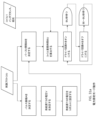
病状を処置する方法であって、前記方法は、
1つ以上の埋め込まれた細長い導体を伴う患者を識別することと、
前記患者の処置部位の表面に対して外部磁場発生器のコイルを設置することと、
磁場を前記1つ以上の埋め込まれた細長い導体に印加することにより、治療用神経刺激を発生させることと
を含む、方法。
(項目41)
前記処置部位における活動電位活性を変調、増加、または減少させるために発生させられる前記磁場を活性化することをさらに含む、項目40に記載の方法。
(項目42)
前記活動電位活性は、脳、感覚系、または神経筋系内の神経細胞内に位置する、項目40または41に記載の方法。
(項目43)
疼痛障害、精神障害、感覚障害、または筋障害の処置において使用される、項目40-42のいずれか1項に記載の方法。
(項目44)
前記疼痛障害は、切断、神経障害、神経損傷、または傷害に起因する、項目43に記載の方法。
(項目45)
前記精神障害は、鬱病、ハンチントン病、アルツハイマー病、認知症、不安神経症、不眠症、外傷後ストレス障害、またはパニック発作である、項目43に記載の方法。
(項目46)
100ピークアンぺア未満および100ボルト未満のピーク電圧を使用して前記磁場を発生させることをさらに含む、項目40に記載の方法。
(項目47)
処置デバイスであって、前記処置デバイスは、
シリンジ本体と、
前記シリンジ本体内に位置しているスライドするプランジャと、
前記シリンジ本体に取り付けられた針と
を備え、
少なくとも1つの個別の細長い導体が、前記シリンジ本体内に位置し、前記シリンジ本体および針は、前記少なくとも1つの細長い導体の向きを拘束し、
前記細長い導体は、100ミクロン未満の直径を有するモノリシック金属本体を備えている、処置デバイス。
(項目48)
前記モノリシック金属本体は、10mm未満の長さを有する、項目47に記載の処置デバイス。
(項目49)
神経変調システムであって、前記システムは、
少なくとも1つの細長い導体であって、前記少なくとも1つの細長い導体は、10ミリメートル未満の長さと、1ミリメートル未満の前記長さに対して横の寸法とを有し、神経、軸索、または神経細胞に隣接した埋め込み、またはそれに対する埋め込みのために構成されている、少なくとも1つの細長い導体と、
磁場発生器と
を備え、
前記磁場発生器は、前記少なくとも1つの細長い導体から間隔を置かれており、誘導され、集中させられた電場を前記少なくとも1つの細長い導体において発生させるように構成されている、
神経変調システム。
(項目50)
前記少なくとも1つの細長い導体は、注入デバイス内および密閉無菌包装内に事前装填される、項目49に記載の神経変調システム。
(項目51)
前記少なくとも1つの細長い導体は、前記注入デバイス内に連続的に位置付けられた複数の細長い導体である、項目50に記載の神経変調システム。
(項目52)
前記磁場発生器は、再充電可能バッテリをさらに備えている、項目49-51のいずれか1項に記載の神経変調システム。
(項目53)
前記磁場発生器は、筐体内に位置しており、前記筐体は、人体上の場所、または人体によって装着される服装もしくはそのポケット内の場所に前記筐体を取り付けるように構成された調節可能ストラップ、弾性バンド、ベルクロ(登録商標)、バックル、接着テープ、またはピンを備えている、項目52に記載の神経変調システム。
(項目54)
前記筐体は、前記人体上の前記場所における皮膚表面に対して1センチメートル未満である高さを有する、項目53に記載の神経変調システム。
(項目55)
患者を処置する方法であって、前記方法は、
神経、軸索、神経細胞、または神経組織に対して、またはそれに隣接して少なくとも1つの細長い導体を挿入することであって、前記導体は、10ミリメートル未満の長さと、1ミリメートル未満の前記長さに対して横の寸法とを有する、ことと、
前記少なくとも1つの細長い導体から間隔を置かれた場所に磁場発生器を位置付けることと、
前記磁場発生器を使用して、誘導され、集中させられた電場を少なくとも1つの細長い導体に提供することと
を含む、方法。
(項目56)
前記磁場発生器は、複数の磁気コイル、ドライバ回路、および再充電可能バッテリを伴う筐体を備えている携帯型磁場発生器である、項目55に記載の方法。
(項目57)
前記複数の磁気コイルは、3センチメートル未満の正味厚さを有する、項目56に記載の方法。
(項目58)
前記少なくとも1つの細長い導体から間隔を置かれた場所は、皮膚表面に対している、項目56に記載の方法。
(項目59)
ストラップ、弾性バンド、ベルクロ(登録商標)、バックル、接着テープ、ピン、またはポケットを使用して、前記磁場導体の前記場所を維持することをさらに含む、項目56に記載の方法。
(項目60)
外部コイル刺激システムを備えている磁気刺激システムであって、前記磁気刺激システムは、患者の組織表面に対する使用のために構成され、前記磁気刺激システムは、100ピークアンペア以下の瞬間電流および100ピークボルト以下の電力供給源電圧のうちの少なくとも1つを使用して、治療中に治療用磁場を発生させるように構成されている、磁気刺激システム。
(項目61)
前記外部コイル刺激システムは、100アンペア以下の瞬間電流のアンペア数限界で構成されている、項目59に記載の磁気刺激システム。
(項目62)
前記外部コイル刺激システムは、100ボルト以下の電圧限界で構成されている、項目59または60に記載の磁気刺激システム。
(項目63)
前記外部コイル刺激システムは、刺激信号が前記外部コイル刺激システムとコンデンサとの間の共振の時間における一部であるように、前記コンデンサと並列に接続されている、項目60に記載の磁気刺激システム。
(項目64)
前記並列のコンデンサおよびコイルは、一方の側のDC電力供給源と他方の側の接地へのスイッチとによって活性化されるように構成され、スイッチ開とスイッチ閉との間の期間は、1つ以上の刺激パルスになる前記共振の前記一部を決定する、項目60に記載の磁気刺激システム。
(項目65)
前記スイッチは、トランジスタと整流器との組み合わせであり、開閉動作は、電圧を前記トランジスタのゲートまたはベースに印加することによって前記トランジスタをオンまたはオフにすることによって起こるように構成されている、項目64に記載の磁気刺激システム。
(項目66)
前記開閉動作は、第1の全共振サイクルの始めに開き、前記第1のサイクルの終わりに先立って、前記サイクルの終わりに、複数のサイクルの終わりに、または、後のサイクル内で閉じるように構成されている、項目63-65のいずれか1項に記載の磁気刺激システム。
(項目67)
前記スイッチは、パルス連続の間に前記コイル内の電流によって消費される電気エネルギーを節約するために、減衰共振パルスの連続の直前に前記トランジスタの前記ゲートまたはベースをオフにし、そして、次の減衰連続に先立って刺激装置内に電流を蓄積するためにオンにされるように構成されている、項目65または66に記載の磁気刺激システム。
(項目68)
前記並列のコンデンサおよびコイルは、4つのスイッチを有するHドライバによって活性化される、項目60に記載の磁気刺激システム。
(項目69)
各スイッチは、トランジスタと整流器とを備えている、項目68に記載の磁気刺激システム。
(項目70)
共振サイクルの第1の半分の始めに、前記4つのスイッチのうちの第1の2つは、開くように構成され、前記4つのスイッチのうちの第2の2つは、閉じるように構成され、前記共振サイクルの第2の半分の終わりに、前記4つのスイッチのうちの前記第1の2つは、閉じるように構成され、前記4つのスイッチのうちの前記第2の2つは、開くように構成されている、項目68または69に記載の磁気刺激システム。
In one embodiment, configured for use against a tissue surface of a patient, using at least one of an instantaneous current of 100 peak amperes or less and a power supply voltage of 100 peak volts or less, the therapeutic A magnetic stimulation system is provided that includes an external coil stimulation system configured to generate a magnetic field. The external coil stimulation system may be configured with an amperage limit of 100 amps or less of instantaneous current. The external coil stimulation system can be configured with a voltage limit of 100 volts or less. The external coil stimulation system can be connected in parallel with the capacitor so that the stimulation signal can be part of the time of resonance between the external coil stimulation system and the capacitor. The parallel capacitor and external coil stimulation system is configured to be activated by a DC power supply on one side and a switch to ground on the other side, with a period between switch open and switch closed of 1 Determine the portion of the resonance that results in one or more stimulation pulses. A switch may be a combination of a transistor and a rectifier, and the switching action may be configured to occur by turning the transistor on or off by applying a voltage to the gate or base of the transistor. The opening and closing action of the switch is configured to open at the beginning of the first full resonant cycle and close prior to the end of the first cycle, at the end of the cycle, at the end of a plurality of cycles, or within a later cycle. can be The switch is configured to turn off the gate or base of the transistor just prior to a train of decaying resonant pulses, and is turned on to build up current in the stimulator prior to the next decaying train of pulse trains. It can save the electrical energy consumed by the current in the coil during A parallel capacitor and coil can be activated by an H-driver with four switches. Each switch may comprise a transistor and a rectifier. At the beginning of the first half of the resonant cycle, the first two of the four switches may be configured to open and the second two of the four switches may be configured to close. Thus, at the end of the second half of the resonant cycle, the first two switches are configured to close and the second two switches are configured to open.
The present invention provides, for example, the following.
(Item 1)
A neuromodulation system, said system comprising:
a. At least one elongated conductor configured for placement inside the body, the at least one elongated conductor having one end adjacent the site to be stimulated an elongated conductor;
b. a magnetic field generator positioned outside the body and configured to generate a time-varying magnetic field perpendicular to the longitudinal axis of the conductor;
A system that has
(Item 2)
The system of
(Item 3)
3. The system of
(Item 4)
The system of
(Item 5)
5. The system of
(Item 6)
2. The system of
(Item 7)
The system of any one of items 1-6, wherein the elongated conductor comprises a cylindrical shape having a diameter and a length, the diameter being less than the length.
(Item 8)
8. The system of
(Item 9)
The system of any one of items 1-8, wherein the elongated conductor is injected into the body through a guide tube.
(Item 10)
10. The system of item 9, wherein the guide tube comprises a needle of a syringe.
(Item 11)
2. The system of
(Item 12)
12. The system of item 11, further wherein the magnetic field generator is connected in parallel with the capacitor such that the stimulation signal is part of the time of resonance between the coil and the capacitor.
(Item 13)
The parallel capacitor and coil are configured to be activated by a DC power supply on one side and a switch to ground on the other side, the period between switch opening and switch closing being equal to the
(Item 14)
(Item 15)
The opening and closing action opens at the beginning of a first full resonance cycle and closes prior to the end of the first cycle, at the end of the cycle, at the end of a plurality of cycles, or within a later cycle. 15. The system of any one of items 12-14, configured.
(Item 16)
The switch turns off the gate or base of the transistor just before a train of decaying resonance pulses to save the electrical energy consumed by the current in the coil during the pulse train, and the following damping. 16. The system of item 14 or 15, configured to be turned on to build up current in the stimulator prior to continuation.
(Item 17)
13. The system of item 12, wherein the parallel capacitor and coil are activated by an H-driver having four switches.
(Item 18)
18. The system of item 17, wherein each switch comprises a transistor and a rectifier.
(Item 19)
At the beginning of the first half of the resonant cycle, two of the four switches are configured to open, the other two switches are configured to close, and at the beginning of the second half of the resonant cycle. Finally, a system according to item 17 or 18, arranged for the opposite to occur.
(Item 20)
20. Any one of paragraphs 1-19, wherein the magnetic field generator comprises a stimulator coil, the stimulator coil comprising a material having a high magnetic permeability configured to contain a fringe field. system.
(Item 21)
21. The system of item 20, wherein the material with high magnetic permeability comprises rigid or flexible ferrite, steel, or iron.
(Item 22)
21. The system of item 20, wherein the coil further comprises a conductive ferromagnetic material that reduces the amplitude of subsequent resonant pulses relative to previous pulses.
(Item 23)
23. The system of item 22, wherein the material comprises iron, cobalt, nickel, steel, or alloys or other combinations thereof.
(Item 24)
12. The system of item 11, wherein the one or more coil windings are in a plane or in multiple adjacent planes.
(Item 25)
25. The system of item 11 or 24, wherein the one or more coil windings comprise magnet wire.
(Item 26)
25. The system of items 11 or 24, wherein the one or more coil windings comprise metal deposited on a layered substrate.
(Item 27)
27. The system of item 26, wherein the substrate is rigid.
(Item 28)
28. The system of item 27, wherein the substrate comprises FR-4 glass reinforced epoxy laminate, glass, or rigid plastic.
(Item 29)
27. The system of item 26, wherein the substrate is flexible.
(Item 30)
30. The system of item 29, wherein the substrate comprises polyimide, BoPET, polyethylene, polyurethane, nylon, or PTFE.
(Item 31)
The system of
(Item 32)
32. According to
(Item 33)
The system of
(Item 34)
The system of
(Item 35)
2. The system of
(Item 36)
2. The system of
(Item 37)
The system of
(Item 38)
said elongated conductor comprises a first end, a second end and a body therebetween and has a length from said first end to said second end of 10 mm or less; The system of
(Item 39)
39. The system of item 38, wherein none of the first end, the second end, or the body is connected to another conductor.
(Item 40)
A method of treating a medical condition, said method comprising:
identifying a patient with one or more implanted elongated conductors;
placing coils of an external magnetic field generator against the surface of the patient's treatment site;
generating therapeutic neural stimulation by applying a magnetic field to the one or more implanted elongated conductors;
A method, including
(Item 41)
41. The method of
(Item 42)
42. The method of
(Item 43)
43. A method according to any one of items 40-42 for use in the treatment of pain disorders, psychiatric disorders, sensory disorders or myopathies.
(Item 44)
44. The method of item 43, wherein the pain disorder results from amputation, neuropathy, nerve injury, or injury.
(Item 45)
44. The method of item 43, wherein the mental disorder is depression, Huntington's disease, Alzheimer's disease, dementia, anxiety, insomnia, post-traumatic stress disorder, or panic attacks.
(Item 46)
41. The method of
(Item 47)
A treatment device, said treatment device comprising:
a syringe body;
a sliding plunger located within the syringe body;
a needle attached to the syringe body;
with
at least one separate elongated conductor is positioned within the syringe body, the syringe body and needle constraining an orientation of the at least one elongated conductor;
A treatment device, wherein the elongated conductor comprises a monolithic metal body having a diameter of less than 100 microns.
(Item 48)
48. The treatment device of item 47, wherein the monolithic metal body has a length of less than 10 mm.
(Item 49)
A neuromodulation system, said system comprising:
at least one elongated conductor, said at least one elongated conductor having a length of less than 10 millimeters and a dimension transverse to said length of less than 1 millimeter; at least one elongated conductor configured for implantation adjacent to or relative to
magnetic field generator and
with
the magnetic field generator is spaced from the at least one elongated conductor and configured to generate an induced, focused electric field in the at least one elongated conductor;
neuromodulation system.
(Item 50)
50. The neuromodulation system of item 49, wherein the at least one elongated conductor is pre-loaded within an injection device and within a sealed sterile packaging.
(Item 51)
51. The neuromodulation system of item 50, wherein the at least one elongated conductor is a plurality of elongated conductors positioned serially within the injection device.
(Item 52)
52. The neuromodulation system of any one of items 49-51, wherein the magnetic field generator further comprises a rechargeable battery.
(Item 53)
The magnetic field generator is located within a housing, the housing being adjustable configured to mount the housing to a location on the human body or within a garment or pocket thereof worn by the human body. 53. The neuromodulation system of item 52, comprising a strap, elastic band, Velcro®, buckle, adhesive tape, or pin.
(Item 54)
54. The neuromodulation system of item 53, wherein the housing has a height that is less than 1 centimeter with respect to the skin surface at the location on the human body.
(Item 55)
A method of treating a patient, said method comprising:
inserting at least one elongated conductor into or adjacent to a nerve, axon, nerve cell, or neural tissue, said conductor having a length of less than 10 millimeters and said length of less than 1 millimeter; having a dimension transverse to the height;
positioning a magnetic field generator at a location spaced from the at least one elongated conductor;
providing an induced and focused electric field to at least one elongated conductor using the magnetic field generator;
A method, including
(Item 56)
56. Method according to item 55, wherein the magnetic field generator is a portable magnetic field generator comprising a housing with a plurality of magnetic coils, a driver circuit and a rechargeable battery.
(Item 57)
57. The method of item 56, wherein the plurality of magnetic coils has a net thickness of less than 3 centimeters.
(Item 58)
57. The method of item 56, wherein the location spaced from the at least one elongated conductor is against a skin surface.
(Item 59)
57. The method of item 56, further comprising maintaining said location of said magnetic field conductors using straps, elastic bands, Velcro®, buckles, adhesive tape, pins, or pockets.
(Item 60)
A magnetic stimulation system comprising an external coil stimulation system, said magnetic stimulation system configured for use against a tissue surface of a patient, said magnetic stimulation system having an instantaneous current of less than 100 peak amperes and 100 peak volts. A magnetic stimulation system configured to generate a therapeutic magnetic field during treatment using at least one of the following power supply voltages:
(Item 61)
60. The magnetic stimulation system of item 59, wherein the external coil stimulation system is configured with an amperage limit of 100 amps or less of instantaneous current.
(Item 62)
61. Magnetic stimulation system according to item 59 or 60, wherein the external coil stimulation system is configured with a voltage limit of 100 volts or less.
(Item 63)
61. The magnetic stimulation system of item 60, wherein the external coil stimulation system is connected in parallel with the capacitor such that the stimulation signal is part of the time of resonance between the external coil stimulation system and the capacitor. .
(Item 64)
The parallel capacitor and coil are configured to be activated by a DC power supply on one side and a switch to ground on the other side, the period between switch opening and switch closing being one. 61. Magnetic stimulation system according to item 60, for determining said part of said resonance resulting in said stimulation pulse.
(Item 65)
Item 64, wherein the switch is a combination of a transistor and a rectifier, and the opening and closing action is configured to occur by turning the transistor on or off by applying a voltage to the gate or base of the transistor. The magnetic stimulation system as described in .
(Item 66)
The opening and closing action opens at the beginning of a first full resonance cycle and closes prior to the end of the first cycle, at the end of the cycle, at the end of a plurality of cycles, or within a later cycle. 66. The magnetic stimulation system of any one of items 63-65, configured.
(Item 67)
The switch turns off the gate or base of the transistor just before a train of decaying resonance pulses to save the electrical energy consumed by the current in the coil during the pulse train, and the following damping. 67. A magnetic stimulation system according to item 65 or 66, configured to be turned on to build up current in the stimulator prior to continuation.
(Item 68)
61. The magnetic stimulation system of item 60, wherein the parallel capacitors and coils are activated by an H-driver having four switches.
(Item 69)
69. Magnetic stimulation system according to item 68, wherein each switch comprises a transistor and a rectifier.
(Item 70)
At the beginning of the first half of the resonant cycle, the first two of said four switches are arranged to open and the second two of said four switches are arranged to close. , at the end of the second half of the resonant cycle, the first two of the four switches are configured to close and the second two of the four switches are open. 70. A magnetic stimulation system according to item 68 or 69, configured to:
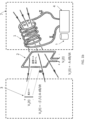
この神経刺激システムの一例示的実施形態は、患者の外面に結合され得る磁場発生器を含む外部またはウェアラブル部分と、標的化された神経線維もしくは神経細胞、または神経線維もしくは神経細胞の群のみを活性化するために刺激装置の電場を集中させる内部または埋め込み注入可能部分とを備えている。図1aに描写されるように、神経変調システム7は、ウェアラブル部分3を備え、ウェアラブル部分は、刺激装置コイル1を備え、刺激装置コイル1は、ドライバ回路4によって駆動され、バッテリ5および/または他の電源によって給電される。ドライバ回路4は、処理またはコンピュータユニットを含み得、処理またはコンピュータユニットは、ユーザの場所において、または遠隔場所から、WiFi、Bluetooth(登録商標)、RFID、または類似するネットワークもしくは無線プロトコルを経由して、スマートフォンまたは他のデバイスへのインターフェースを介して、刺激装置コイル1への駆動信号を発生させることと、ユーザまたは医療提供者から刺激パラメータにおける調節を可能にするための入力を受信することとを行う。ウェアラブル部分7は、ストラップ、弾性バンド、ベルクロ(登録商標)、バックル、接着テープ、ピン、または類似する機構によって身体に取り付けられ、刺激装置コイルは、皮膚に面する。代替として、ウェアラブル部分は、ポケット、クランプ、ピン、接着テープ、ベルクロ(登録商標)、または他の好適な取り付け手段を使用して、衣類もしくは他の服装に取り付けられ得る。衣類または服装内で、ウェアラブル部分の適切な場所は、刺激の場所およびタイプに依存する。
One exemplary embodiment of this neurostimulation system includes an external or wearable portion that includes a magnetic field generator that can be coupled to the patient's external surface and only targeted nerve fibers or neurons, or groups of nerve fibers or neurons. an internal or implantable injectable portion that concentrates the electric field of the stimulator for activation. As depicted in FIG. 1a, a
図1aの刺激装置コイル1内で流動する電流は、硬質および軟質組織を含む身体の深くに容易に貫通する変化する磁場を生み出す。この変化する磁場は、ファラデーの電磁気学の法則によって、電場を誘導し、電場は、1つ以上の注入可能部分もしくは構成要素3内に集中させられ、身体も貫通する。いくつかの実施形態では、この誘導電場は、より大きい面積効果またはより小さい局在効果を伴って発生し、注入可能導体3の直近の場所を除いて身体の神経系を改変するように構成され得る。刺激装置コイル1からの変化する磁場は、注入可能導体3内の自由電子を移動させる電場を誘導し、一方の端点が正に帯電され、他方の端部が負に帯電されるようにする。注入可能導体3の端点間のこの誘導電圧は、次いで、端点場所に設置され、ある電圧で活性化される2つの電極のように作用する。この活性化は、先端電圧が静止電位を誘起電位を超えて上昇させるために十分である場合、注入可能導体3の先端の近傍のイオンを移動させ、近傍の神経細胞または軸索における活動電位もしくは活動電位の流れを引き起こす。
Current flowing within the
多種多様なコイルが、神経刺激装置の種々の実施形態と共に使用され得る。巻数は、20~300、または約40~約200、または約10~約150、もしくはそれを上回るものまで変動することができる。より多くの巻数は、コイルのインダクタンスを増加させ、それは、ドライバ回路内のトランジスタおよび整流器の電圧定格を増加させるが、所与の磁場を生み出すために要求される電流を低下させる。 A wide variety of coils may be used with various embodiments of neurostimulators. The number of turns can vary from 20 to 300, or from about 40 to about 200, or from about 10 to about 150, or more. More turns increases the inductance of the coil, which increases the voltage rating of the transistors and rectifiers in the driver circuit, but lowers the current required to produce a given magnetic field.
コイル巻きの直径は、刺激のために必要とされる貫通深さに基づいて選択され得る。いくつかの実施形態では、コイルの直径は、要求される貫通深さの約4倍である。いくつかの神経は、皮膚表面から1cm以内にあり、4cm直径のコイルを、ほぼ適切なサイズにする。肥満者の脊髄内等の他の刺激場所は、10cmの深さであり得、最適なコイル直径を、最も低い電力消費のために約40cmにする。この場合、より大きい電力で駆動されるより小さいコイルが、より実践的であり得る。Hコイルおよび8の字コイル等の独特なコイルが、ある貫通深さにおいてより強力な、またはより集中させられた磁気を発生させることが示されており、これらのコイルは、この刺激装置との使用のために有利であり得る。そして、いくつかの変形例では、コイル直径(または平均横断寸法)は、約2cm~約50cm、または約3cm~約40cm、もしくは約4cm~約25cmの範囲内である。 The coil winding diameter can be selected based on the penetration depth required for stimulation. In some embodiments, the coil diameter is about four times the required penetration depth. Some nerves are within 1 cm of the skin surface, making a 4 cm diameter coil about the right size. Other stimulation locations, such as in the spinal cord of obese individuals, can be 10 cm deep, making the optimal coil diameter about 40 cm for lowest power consumption. In this case, smaller coils driven with higher power may be more practical. Unique coils, such as the H-coil and the figure-eight coil, have been shown to generate stronger or more concentrated magnetism at certain penetration depths, and these coils are associated with this stimulator. can be advantageous for use. And, in some variations, the coil diameter (or average transverse dimension) is within the range of about 2 cm to about 50 cm, or about 3 cm to about 40 cm, or about 4 cm to about 25 cm.
コイル内で使用されるワイヤの直径は、コイルの電気抵抗を決定し、したがって、注入可能場所において必要とされる磁場を発生させるために要求される電流の量を考慮して、それが発生させる熱の量を決定する。より小さい直径のワイヤは、より大きい直径のワイヤよりも多くの熱を発生させるが、より大きい直径のワイヤは、刺激装置のウェアラブル部分により多くの重量を追加する。殆どの実施形態では、ワイヤの直径は、直径0.3~2.3mmであり、より小さい直径が、より低い貫通深さのために典型的である。他の実施形態では、ワイヤ直径または幅は、約0.5mm~約3mm、または約0.4mm~約2.5mm、もしくは約0.2mm~約3mmの範囲内であり得る。 The diameter of the wire used within the coil determines the electrical resistance of the coil and thus the amount of current required to generate the required magnetic field at the injectable site, given that it generates Determine the amount of heat. Smaller diameter wires generate more heat than larger diameter wires, but larger diameter wires add more weight to the wearable portion of the stimulator. In most embodiments, the diameter of the wire is 0.3-2.3 mm in diameter, with smaller diameters typical for lower penetration depths. In other embodiments, the wire diameter or width can range from about 0.5 mm to about 3 mm, or from about 0.4 mm to about 2.5 mm, or from about 0.2 mm to about 3 mm.
神経刺激装置のためのコイルは、活動電位を刺激するために十分な電圧を注入可能物に誘導するための0.001~0.1テスラの磁場強度を発生させるように構成され得る。磁場強度は、誘導電圧が磁場の時間微分に比例するので、より狭いパルス幅に対してより小さくあり得る。対照的に、従来技術のTMSシステムは、誘導電場が本明細書に説明されるように注入可能物によって集中させられないので、1~5テスラの磁場強度を要求する。本明細書に説明される磁場強度は、パルスバースト中に瞬間的に2~20アンペアのコイル電流で達成されることができ、バーストの合間にオフになる実施形態において平均0.2~5.0アンペアのコイル電流で達成されることができる。対照的に、従来技術のTMSシステムは、数百または数千アンペアの瞬間コイル電流を要求する。 A coil for a neurostimulator may be configured to generate a magnetic field strength of 0.001-0.1 Tesla to induce a voltage in the injectable sufficient to stimulate an action potential. The magnetic field strength can be smaller for narrower pulse widths because the induced voltage is proportional to the time derivative of the magnetic field. In contrast, prior art TMS systems require magnetic field strengths of 1-5 Tesla because the induced electric field is not concentrated by the injectables as described herein. The magnetic field strengths described herein can be achieved with coil currents of 2 to 20 amps instantaneously during pulse bursts, averaging 0.2 to 5.0 amps in embodiments that are turned off between bursts. A coil current of 0 amps can be achieved. In contrast, prior art TMS systems require hundreds or thousands of amps of instantaneous coil current.
パルス幅、バースト速度、立ち上がりパルス振幅、および立ち上がりパルス極性(軸索または神経細胞の分極化もしくは脱分極化)は、刺激プロトコルによって定義され、それらは、典型的には、この神経刺激装置に対して、この刺激装置の共振特性を受ける従来技術の有線電極システムのために要求されるものと同一である。典型的には、パルス幅は、20マイクロ秒~1ミリ秒であり、バースト速度は、10Hz~200Hzである。従来技術の有線電極の立ち上がりパルス振幅は、典型的には、10マイクロアンペア~1,500マイクロアンペアの分極または脱分極電流を発生させるが、軸索または神経細胞において必要とされる実際の電流は、10~20マイクロアンペアである。より大きい電流が、分散のために必要とされ、分散は、軸索または神経細胞に十分に近接して位置付けられていない電極からもたらされるか、または、インプラント構成要素と軸索または神経細胞との間に有意な髄鞘形成もしくは神経周膜層が存在する場合にもたらされ得る。この神経刺激装置では、注入可能物は、刺激される神経、神経束、神経線維、または神経細胞に可能な限り近接して設置される。したがって、注入可能物によって生み出される電流は、10~50マイクロアンペアであり、それは、次に、有髄末梢神経に対して注入可能物の端点間に20~100ミリボルトを要求し、無髄軸索もしくは神経細胞に対して10~20ミリボルトを要求する。注入可能物の長さに応じて、注入可能物において必要とされる電場強度は、10mm注入可能物と結合された10ミリボルトのための1.0ボルト/メートルと、1mm注入可能物と結合された100ミリボルトのための100ボルト/メートルとの間である。 Pulse width, burst rate, leading edge pulse amplitude, and leading edge pulse polarity (polarization or depolarization of axons or neurons) are defined by the stimulation protocol and are typically specified for this neurostimulator. are identical to those required for prior art wired electrode systems subject to the resonant characteristics of this stimulator. Typically, the pulse width is 20 microseconds to 1 millisecond and the burst rate is 10 Hz to 200 Hz. The rising pulse amplitude of prior art wired electrodes typically produces polarizing or depolarizing currents of 10 microamps to 1,500 microamps, but the actual current required in an axon or neuron is , 10-20 microamps. Larger currents are required for dispersion, which may result from electrodes that are not positioned close enough to the axon or neuron, or the interaction of the implant component with the axon or neuron. It can result when there is significant myelination or perineural layer in between. In this neurostimulator, the injectable is placed as close as possible to the nerve, nerve bundle, nerve fiber, or nerve cell to be stimulated. Thus, the current produced by the injectable is 10-50 microamps, which in turn requires 20-100 millivolts between the end points of the injectable for myelinated peripheral nerves and unmyelinated axons. Or it requires 10-20 millivolts for nerve cells. Depending on the length of the injectable, the electric field strength required at the injectable is 1.0 volts/meter for 10 millivolts coupled with 10 mm injectable and between 100 volts/meter for 100 millivolts.
立ち上がり刺激パルスは、パルスのバースト内で繰り返され得る。多くの場合、神経系内の電荷蓄積を回避するために、各バーストが正および負のパルスの両方を含むことが所望される。刺激の複数のバーストは、概して、身体に複数の活動電位を発生させる。 A rising stimulus pulse may be repeated within a burst of pulses. It is often desired that each burst contain both positive and negative pulses to avoid charge build-up within the nervous system. Multiple bursts of stimulation generally generate multiple action potentials in the body.
人体の活動電位は、典型的には、パルス周波数変調され、それは、信号の強度が繰り返し率によって決定されることを意味する。したがって、図1のドライバ回路4は、所望の繰り返し率において刺激バーストを繰り返すであろう。多くの治療および用途では、身体が刺激装置からの種々の刺激パルス形状に応答してそれ自体の活動電位を生み出すので、刺激された電圧波形が身体の活動電位波形を模倣することは必要ではない。しかしながら、時間が短すぎるパルスは、神経を刺激しないこともあり、時間が長すぎるパルスは、所望の効果のために要求されるバースト速度を達成しないこともある。
Action potentials in the human body are typically pulse frequency modulated, meaning that the strength of the signal is determined by the repetition rate. Thus,
再び図1aの例示的神経変調システムを参照すると、神経刺激装置は、変圧器として特徴付けられ得、注入可能導体3は、何分の1かの巻きを有する二次巻き線のようなものである。例えば、注入可能導体3内の誘導電圧は、図1bの単巻き誘導コイル2内の誘導電圧のl/Lとして特徴付けられ得、ここで、lは、注入可能物3の長さであり、Lは、単巻き誘導コイル2の長さである。この関係は、そうでなければ測定することが困難である注入可能導体3における誘導電圧を決定するための1つの方法である。
Referring again to the exemplary neuromodulation system of FIG. 1a, the neurostimulator can be characterized as a transformer and the
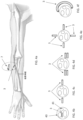
図1aの注入可能導体3の機能の別の考慮事項は、電場集中器としてのものである。任意の細長い伝導性物体が、図2aに図示されるように、それを包囲する電場を自然に集中させるであろう。図2b-2fは、注入可能導体3を備えている円筒形の形状における細長い直線導体を示し、この導体は、絶縁層を有することも、有しないこともあり、伝導性部分が、各端部上に露出されている。図2bの注入可能導体3は、埋め込まれた刺激装置内で使用される長いワイヤのセグメントであり得ることに留意されたい。これらのワイヤは、市場ですでに入手可能であり、長い期間にわたって人体の内側で安全であることがすでに試験されている。描写される実施形態では、その長さに沿った導体の断面形状は、均一であるが、他の例では、断面形状またはサイズは、その長さに沿って変動し得る。他の例では、導体は、弓形形状もしくは1つ以上の角度のある曲がり部を有し得る。
Another consideration of the function of the
図1aおよび1bの刺激装置コイル1によって生み出される誘導電圧V2(t)の振幅は、公式V2(t)=(l/L)×A×dB/dtによって導体の長さlに比例し、式中、Lは、単巻き誘導コイルの長さである。Aは、単巻き誘導コイルの断面積である。図1bの単巻き誘導コイル2の面積Aは、(L/4)2である。Bは、刺激装置コイルによって生み出される磁場であり、それは、次に、刺激装置コイル内で流動する電流に比例する。
The amplitude of the induced voltage V2 (t) produced by the
刺激装置コイルの断面寸法L/4は、典型的には、1~20cmであり、それは、ウェアラブルとして快適であるように十分に小さい必要があるが、注入可能導体に到達するための貫通深さも有する。迷走神経のような注入可能物のためのいくつかの刺激部位は、1~2cm以内にあるが、脊髄のような他の刺激部位は、肥満患者に関して20cmの深さであり得る。 The cross-sectional dimension L/4 of the stimulator coil is typically 1-20 cm, which needs to be small enough to be comfortable as a wearable, but also the penetration depth to reach the injectable conductors. have. Some stimulation sites for injectables, such as the vagus nerve, are within 1-2 cm, while other stimulation sites, such as the spinal cord, can be as deep as 20 cm for obese patients.
第1の端部から第2の端部までの注入可能導体の長さは、典型的には、1~10mmである。導体は、別個であり、導体の第1の端部、第2の端部、または本体は、任意の他の導体構造に取り付けられないが、随意に、患者の身体内での導体の生体適合性を変調するための本明細書に説明されるような材料を用いてコーティングされ得る。いくつかの変形例では、導体は、直線であり、いかなる曲線、角度付き曲がり部、または分岐セグメントも伴わない。他の変形例では、導体は、曲線または角度付き曲がり部領域を有し得るが、曲線または角度は、合計で5度、10度、15度、20度、25度、30度、35度、40度、または45度未満に角度付けられる。いくつかの例では、この範囲内の長さは、刺激するために十分な誘導電圧を生み出すために十分に長いが、身体移動からの変位、不快感、および周辺組織との干渉等の身体内の合併症を引き起こさないように十分に短くあり得る。ある場合、注入可能物は、それが胸部または脊椎内に位置する場合、100mmと同程度に長くあり得る。より長い注入可能物は、端点においてより高い誘導電圧を発生させ、それは、ウェアラブル磁場発生器のためにより低い電力およびより長いバッテリ寿命を提供し得る。他の例では、導体は、約2~30mm、4~20mm、または約3~15mmの長さを有し得る。注入可能導体の縦方向軸に対する直径または横断断面寸法は、典型的には、8~50ミクロンであり、それは、神経または神経細胞の十分な面積にわたって電圧を印加するために十分に厚く、身体の通常の活動中に曲がらないように物理的に十分に強いが、シリンジまたは他の注入デバイスを通して注入可能でもあるように十分に薄い。これらの薄い注入可能物は、単一の神経線維または線維もしくは神経細胞の小群のための高度に標的化された刺激のために効果的である。大きい神経束のために、および筋刺激のために、刺激の断面は、大きくあるべきであり、これらの場合、注入可能物は、最大4mmの直径を有し、依然として、標準的ゲージシリンジ針によって収容され得る。 The length of the injectable conductor from the first end to the second end is typically 1-10 mm. The conductor is separate and the first end, second end, or body of the conductor is not attached to any other conductor structure, but optionally biocompatibility of the conductor within the patient's body. It can be coated with materials as described herein for modulating properties. In some variations, the conductors are straight, without any curves, angled bends, or branching segments. In other variations, the conductor may have curved or angled bend regions, but the curves or angles total 5 degrees, 10 degrees, 15 degrees, 20 degrees, 25 degrees, 30 degrees, 35 degrees, Angled at 40 degrees, or less than 45 degrees. In some instances, lengths within this range are long enough to produce sufficient induced voltages to stimulate, but may also cause internal body movements such as displacement from body movement, discomfort, and interference with surrounding tissue. can be sufficiently short so as not to cause complications of In some cases, the injectable can be as long as 100 mm when it is located in the chest or spine. Longer injectables generate higher induced voltages at the endpoints, which can provide lower power and longer battery life for wearable magnetic field generators. In other examples, the conductor can have a length of about 2-30 mm, 4-20 mm, or about 3-15 mm. The diameter or transverse cross-sectional dimension of the injectable conductor relative to the longitudinal axis is typically 8-50 microns, and it is thick enough to apply a voltage over a sufficient area of a nerve or nerve cell to allow it to pass through the body. Physically strong enough not to bend during normal activity, but thin enough to also be injectable through a syringe or other injection device. These thin injectables are effective for highly targeted stimulation of single nerve fibers or small groups of fibers or nerve cells. For large nerve fascicles and for muscle stimulation, the stimulation cross-section should be large, in which case the injectable has a diameter of up to 4 mm and can still be injected with a standard gauge syringe needle. can be accommodated.
前で記述されるように、神経刺激装置のある実施形態は、注入可能デバイス、すなわち、シリンジによって設置され得る小型かつ非常に薄い円筒形デバイスのみを利用し、システムを本質的に低侵襲性にする。コイン、ピル、または長アンテナタイプインプラントを要求する従来技術の刺激装置は、身体の内側に設置されるために有意な外科手術を要求し、これらは、同様に身体の内側に位置する電源に接続されなければならず、それは、構成要素を埋め込むために組織切開を要求し得る。他の例では、Bioness(Valencia,CA)から入手可能な刺激装置のように、磁気誘導充電器システムの一部は、身体の内側に位置し、他の部分は、外側に位置し、それらの間に近接した間隔を伴う2つのコイルを要求する。Stimwave(Pompano Beach,FL)からのRF結合デバイスは、RF結合を使用し、脊髄面積に到達するために身体の内側に長い45cmのアンテナを要求する。Advanced Bionics(Valencia,CA)からの第US6735474 B1号に説明される別のRF結合無線刺激装置は、より小さい螺旋アンテナを有するが、内部バッテリは、それが皮膚の表面の非常に近傍に位置するときのみ無線で再充電されることができる。RF結合は、身体の中に短い距離を進行しよう試みるときでも損失を生じる。対照的に、本明細書に説明される神経刺激装置のある実施形態は、磁気結合を使用し、単に注入可能であるように埋め込み部分のサイズを著しく縮小する。それらのより大きい、より重い、かつより複雑な構成に起因して、既存のインプラントは、より多くの合併症および潜在的問題を有する傾向がある。それらの重量は、身体移動中に大きなシフトを引き起こし、長いアンテナまたはワイヤは、自然な身体運動によって定位置を外れて引き寄せられ得る。対照的に、神経刺激装置の実施形態の小型注入可能デバイスは、身体運動で変位させられるほど重くなく、定位置を外れて引き寄せを受けるほど長くない。 As previously described, certain embodiments of neurostimulators utilize only injectable devices, i.e., small and very thin cylindrical devices that can be placed by syringe, making the system essentially minimally invasive. do. Prior art stimulators requiring coin, pill, or long antenna type implants require significant surgery to be placed inside the body, and these are similarly connected to a power source located inside the body. must be done, which may require a tissue incision to implant the component. In another example, a portion of the magnetic induction charger system is located inside the body and another portion is located outside, such as the stimulator available from Bioness (Valencia, Calif.). Requires two coils with close spacing between them. The RF coupling device from Stimwave (Pompano Beach, Fla.) uses RF coupling and requires a long 45 cm antenna inside the body to reach the spinal cord area. Another RF-coupled wireless stimulator described in US Pat. No. 6,735,474 B1 from Advanced Bionics (Valencia, Calif.) has a smaller helical antenna, but an internal battery allows it to be positioned very close to the surface of the skin. Only when it can be wirelessly recharged. RF coupling produces losses even when attempting to travel short distances into the body. In contrast, certain embodiments of the neurostimulators described herein use magnetic coupling to significantly reduce the size of the implant so that it is simply injectable. Due to their larger, heavier and more complicated construction, existing implants tend to have more complications and potential problems. Their weight causes large shifts during body movement, and long antennas or wires can be pulled out of position by natural body movements. In contrast, the miniature injectable device of the neurostimulator embodiment is neither heavy enough to be displaced by body movement nor long enough to pull out of position.
図2cは、絶縁体が各端部上で同一の量だけはぎとられた細長い直線導体を示す。露出された伝導性材料の表面積は、磁場発生器によって活性化されるときの細長い導体の端点上の電流密度を決定する。絶縁体のはぎとられた部分の長さを制御することによって、組織にさらされる電流密度は、依然として刺激を達成しながら、組織を損傷させることを回避するように制御されることができる。図2dは、はぎとられた絶縁体が一方の端点上で他の端点と異なる、細長い導体を示す。この差異は、一方の端部が標的化された神経または神経細胞内に活動電位を誘起するために十分な電流密度を有し、他方の端部が標的化されていない神経または神経細胞のための刺激のために不十分な電流密度を有するようにすることができる。大型神経では、または脳では、注入可能物の他の端点が、副作用を防止するために活動電位を誘起すべきではない場合が存在するであろう可能性が高い。限定ではないが、別の端点に対する1つの端点の電流密度は、図2bの各端部における異なる導体直径を用いて、または他方の端点に対して一方の端部上により厚いもしくはより少ない伝導性コーティングを有することによっても達成され得る。注入可能物は、図2fに図示されるように、湾曲または半円形形状に事前形成され得る。この場合、注入可能物は、注入可能物を構成する少なくとも1つの材料が弾性である場合、シリンジの内側にある間に一時的に直線化され、次いで、それがシリンジから出るときにこの形状を再びとり得る。図2eは、1つの注入可能物によって発生させられる電圧の2倍である誘導電圧を2つの内側端点間に発生させる2つの注入可能物を示す。図2eの本構成は、神経または神経細胞内の電流フローを2つの内側端点間に非常に精密に集中させ、より良好な標的化およびより強力な刺激を可能にする。 Figure 2c shows an elongated straight conductor with the same amount of insulation stripped on each end. The surface area of exposed conductive material determines the current density on the endpoints of the elongated conductor when activated by the magnetic field generator. By controlling the length of the stripped portion of the insulation, the current density exposed to the tissue can be controlled to avoid damaging the tissue while still achieving stimulation. Figure 2d shows an elongated conductor in which the stripped insulation differs on one end point from the other. This difference is due to the fact that one end has sufficient current density to induce an action potential in the targeted nerve or neuron and the other end is not targeted. to have insufficient current density for stimulation of In large nerves, or in the brain, it is likely that there will be cases where other endpoints of the injectable should not induce action potentials to prevent side effects. Without limitation, the current density of one endpoint relative to another endpoint can be reduced using different conductor diameters at each end in FIG. 2b or with thicker or less conductive It can also be achieved by having a coating. The injectable may be preformed into a curved or semi-circular shape, as illustrated in FIG. 2f. In this case, the injectable is temporarily straightened while inside the syringe if at least one material making up the injectable is elastic, and then assumes this shape when it exits the syringe. can take again. FIG. 2e shows two injectables that generate an induced voltage between the two inner endpoints that is twice the voltage generated by one injectable. The present configuration of FIG. 2e focuses the current flow within the nerve or neuron very precisely between the two medial endpoints, allowing better targeting and more intense stimulation.
注入可能導体3は、限定ではないが、銅、タングステン、クロム、ステンレス鋼、ニッケル、ニクロム、チタン、金、銀、黄銅、これらの任意の合金、または任意の他の伝導性材料であり得る。または、導体は、電流フローをヒト組織のために安全なレベルに限定するために、炭素、炭素繊維、または他の抵抗性材料を全体もしくは一部において含み得る。しかしながら、いくつかの実施形態では、非強磁性材料が、MRI診断への潜在的干渉を低減させるために、および注入可能物と磁場発生器との間の磁気引力のために使用され得る。再び、限定ではないが、導体は、部分的または完全に、PTFE(ポリテトラフルオロエチレン)、PET(ポリエチレンテレフタラート)、ナイロン、シリコーン、ポリエチレン、ポリウレタン、ラテックス、ポリイミド、BoPET(二軸配向ポリエチレンテレフタラート)、これらの任意の混合物または組み合わせ、もしくは導体を腐食から保護するための他の好適な絶縁体を用いて、および/または周辺組織が有害に反応することを防止するための他の好適な絶縁体を用いて、コーティングもしくは絶縁され得る。絶縁体の厚さは、典型的には、5~100ミクロンであり、ピンホール、傷、または引き裂きに抵抗するか、もしくはそれを回避するために十分に厚いが、シリンジまたは他の注入デバイスの通過を可能にするために十分に薄い。注入可能導体の露出された伝導性部分は、身体組織とより適合性であるさらに別の伝導性材料を用いてコーティングまたはめっきされ得る。
The
図3の注入可能導体3は、各端部間に電圧を生成し、したがって、一方の端部を神経または神経細胞の近傍に設置することは、活動電位を刺激することができる。この誘導電圧のパルス幅、バーストあたりの共振サイクルの数、およびバースト周波数は、図1のウェアラブル部分7から完全に制御可能である。このウェアラブル部分は、活動電位の自然な流れをエミュレートすること、良性であると示されている二相性かつ電荷中性パルス形状を生成すること、または推奨される刺激プロトコルのための任意の他の所望のパルス形状を達成することができる。
The
さらに、図3の注入可能導体3は、単一の神経線維または神経細胞を標的化するために直径または横断断面形状において十分に小さいか、もしくは場合によっては2つ以上の神経細胞または複数の神経線維もしくは神経全体を含むより広い面積を刺激するためにより大きくあり得る。限定ではないが、注入可能導体3は、複数の場所を同時に刺激するために一方または両方の端部に複数のストランドを有し得るか、もしくは複数の注入可能導体が、注入され得る。限定ではないが、これらのストランドうちのいくつかまたは全ては、長い期間にわたって、かつ身体運動の間に位置付けられた導体を保つことに役立つために、身体の内側の設置後に広がり得る。いくつかの処置は、複数の神経、神経線維、または神経細胞が同時に刺激されることを要求する。例えば、1つの筋肉は、完全な筋運動を達成するために、多くの神経線維が刺激されることを要求し得る。脳では、多くの場合、多くの場所が、不安神経症または認知症のような一般的障害を処置するために刺激を必要とする。これらの場合、単一の注入可能導体または複数の注入可能導体上の複数の導体のストランドが、設置され得、1つの刺激装置コイルが、それらの全てを刺激し得るか、または複数の刺激装置コイルが、使用され得る。
Further, the
(刺激装置-身体構成)
図4aは、この神経刺激装置がヒト腕内の末梢神経を励起するために使用され得る様子を示し、注入可能導体3が、設置され、一方の端部は、刺激されるべき神経上にある。この端部は、神経線維上またはその近傍に、もしくは刺激される軸索の細胞膜上またはそのすぐ内側に位置すべきである。注入可能物の活性端点は、神経線維のミエリン層のすぐ外側に位置するか、またはミエリン層を貫通するか、神経線維束のすぐ外側に位置するか、神経周膜層を貫通し得る。注入可能物における刺激電圧振幅は、ミエリンまたは神経周膜層を通して神経を刺激するために、約100ミリボルトである必要がある。注入可能物の端点が神経線維または神経細胞自体に触れている場合、約15ミリボルトのみの振幅が、注入可能物において要求される。刺激するために必要とされる最小電圧を定義する図10の活動電位の静止電位と誘起電位との間の15ミリボルト差を参照されたい。
(stimulator - body composition)
Figure 4a shows how this nerve stimulator can be used to excite a peripheral nerve in a human arm, where an
図4aの注入可能物の他の端点および残りの注入可能導体は、刺激されるべきではない神経および神経細胞を回避し、悪影響を受け得る組織を回避するように向けられるべきである。向きは、通常の身体移動が注入可能導体の活性端点に経時的に定位置でシフトさせないようなものであるべきである。最小電力消費および最大刺激強度に関して、注入可能物の長さ寸法は、コイルからの誘導電場と整列させられるべきである。ファラデーの誘導の法則に基づいて、注入可能導体の長さ寸法は、刺激装置コイルの巻き線に平行であり、それに可能な限り近接し、コイルの中心点から離れるべきである。 The other endpoints of the injectables in Figure 4a and the remaining injectable conductors should be oriented to avoid nerves and nerve cells that should not be stimulated and to avoid tissue that could be adversely affected. The orientation should be such that normal body movements do not cause the active endpoint of the injectable conductor to shift in place over time. For minimum power consumption and maximum stimulation intensity, the injectable length dimension should be aligned with the induced electric field from the coil. Based on Faraday's Law of Induction, the length dimension of the injectable conductor should be parallel to and as close as possible to the turns of the stimulator coil and away from the center point of the coil.
一般に、注入可能物の端点が、刺激される神経、神経線維、または神経線維もしくは神経細胞の群に対してより近接して設置されるほど、ウェアラブルによって消費される電力は、より低くなり、それは、バッテリ寿命を延長すること、またはバッテリサイズを縮小することができる。多くの神経刺激プロトコルでは、神経全体または神経線維の群が、所望の結果を達成するために刺激されなければならない。ヒトにおいて、いくつかの神経の直径は、最大5ミリメートルであり得る。さらに、いくつかの刺激プロトコルは、神経内のある神経線維束が他の線維束に対して優先的に刺激されることを要求し、全ての線維束は、同一の神経内に位置する。図4bは、3つの線維束41を含む例示的神経の断面40を示す。神経自体、線維束の各々、および線維の各々は、高度に絶縁性であるシース内に包まれる。この理由から、神経刺激装置を使用するいくつかの方法は、図4bに図示されるように、神経の内側の注入可能導体の設置を伴い、この注入可能物に最も近接する線維束を刺激させ得る。または、図4cに図示される2つの注入可能物は、神経断面と向かい合って設置され、神経の両側に誘導電圧を発生させ得、この誘導電圧は、図4bの単一の注入可能物のものの2倍である。図4dは、複数の注入物を用いるか、または1つの注入可能物内に複数のストランドを有するかのいずれかによって、複数の導体が設置され得る様子を示す。図4dは、注入可能物が神経断面の下側部分における線維束を優先的に刺激するために偏って設置され得る様子も示す。いくつかの刺激部位では、神経の内側の標的線維束の場所は、把握されていない。この場合、異なる束場所に対処し得る注入可能物の組を有することが、望ましい。図4eは、そのような構成を示す。2つの注入可能物は、神経の上方および下方に設置され、別の2つは、各側に設置される。ここでは、ウェアラブル磁場発生器の回転向きは、4つの注入可能物端点のうちのいずれが軸索の最も強力な分極化を生成するかを決定し、いくつかの異なる線維群のうちの1つが他の3つに対して優先的に刺激されることを可能にするであろう。図4fは、湾曲注入可能物を示し、それは、今日埋め込まれるカフ電極と同様に、神経を抱え込み、より効果的に定位置に留まることができる。図4fの注入可能物の各端点上の露出された導体は、神経の直径を横断する刺激を生成する。限定ではないが、湾曲導体の端点は、同じ方向に偏る線維束を優先的に刺激するために、神経に対して同様に偏り得る。
In general, the closer the infusible endpoint is placed to the nerve, nerve fiber, or group of nerve fibers or nerve cells to be stimulated, the lower the power consumed by the wearable, which is , to extend battery life or reduce battery size. In many nerve stimulation protocols, whole nerves or groups of nerve fibers must be stimulated to achieve desired results. In humans, some nerves can be up to 5 millimeters in diameter. Furthermore, some stimulation protocols require that certain nerve fiber bundles within a nerve be preferentially stimulated over other fiber bundles, all located within the same nerve. FIG. 4b shows a
ウェアラブル刺激装置7は、図4の注入可能導体3の近傍の皮膚上に設置される。限定ではないが、ウェアラブル部分7は、上流神経活動を感知し、神経刺激装置を使用し、末梢神経に外部から橋を架ける回路またはマイクロプロセッサによって駆動され得る。この例では、これらのシステムは、神経障害、傷害、切断、または別の病気によって損傷した神経経路を迂回するために、別のシステムの一部として使用され得る。
A
図5は、この神経刺激装置が迷走神経を励起するために使用され得る様子を示す。この場合、注入可能導体3は、一方の端部が刺激されるべき迷走神経または経路上にある状態に設置され、ウェアラブル部分7は、身体に近接するが、その外側に設置される。限定ではないが、神経刺激装置は、迷走神経刺激によって緩和される癲癇または他の病気を処置することに役立つことができる。公知の刺激部位および兆候は、閉塞性睡眠時無呼吸のための舌下神経、膀胱制御のための後脛骨神経、疼痛軽減のための感知末梢または脊髄神経、偏頭痛のための後頭神経、および癲癇のための迷走神経である。
FIG. 5 shows how this nerve stimulator can be used to excite the vagus nerve. In this case, the
図6bは、神経刺激装置の実施形態が深部脳領域内の神経細胞を励起するために使用され得る様子を示す。この場合、注入可能導体3は、一方の端部を刺激が所望される脳内の場所に伴って設置される。ウェアラブル部分7は、頭部に近接するが、その外側に設置される。限定ではないが、神経刺激装置は、注入可能導体を視床下部、脳弓、嗅内皮質、基底核、または脳の他の面積等の深部脳内に設置することによって、アルツハイマー病、認知症、不安神経症、不眠症、外傷後ストレス障害、パニック発作、および痙攣を処置することができる。
FIG. 6b illustrates how embodiments of neurostimulators can be used to excite neurons in deep brain regions. In this case, the
限定ではないが、図4、5、および6bに示される注入可能導体3は、シリンジまたは他の注入システムを用いて設置され、即時撮像によって適切な場所に誘導され得る。この撮像は、磁気共鳴撮像(MRI)、X線撮像、超音波、または他の身体撮像システムであり得る。
Without limitation, the
これらの例および多くのその他では、神経刺激装置は、従来技術の刺激装置の侵襲性を大幅に低減させ得、その例が、図6aに図示される。従来技術の標的化刺激装置は、広範囲の外科手術、長いワイヤ、大型インプラント、および埋め込みバッテリ充電および/またはバッテリの周期的除去および交換を要求する。これらは、医師および患者の両方に対する大きな技術的困難を表し、非常に高い実装の費用を生じる。 In these examples and many others, neurostimulators can greatly reduce the invasiveness of prior art stimulators, an example of which is illustrated in FIG. 6a. Prior art targeted stimulators require extensive surgery, long wires, large implants, and implanted battery charging and/or periodic removal and replacement of the battery. These represent great technical difficulties for both physicians and patients and result in very high implementation costs.
(刺激装置コイルのためのドライバ回路)
この神経刺激装置のドライバ回路は、刺激コイルの印加電圧、電流、および電力消費を効果的に管理し、これらの数量のうちの1つ、2つ、または3つ全てを低減させる。既存の磁気刺激装置に対して、本明細書に説明される神経刺激装置コイルの種々の実施形態は、より多くの巻きを有し得、それは、より少ない電流フローで同一の磁場強度を発生させることができる。より多くの巻きは、この神経刺激装置コイルがより高いインダクタンスを有すること、またはより多くのエネルギーを貯蔵することを意味する。このエネルギーは、パルス間のDC電流としてコイル内に貯蔵され得、パルスを発生させるとき、並列コンデンサに行ったり、それから来たりさせられる。代替として、DC電流は、パルス間で徐々に消去され得、さらに多くのエネルギーを節約する。
(driver circuit for stimulator coil)
The driver circuitry of this neurostimulator effectively manages the applied voltage, current, and power consumption of the stimulation coils to reduce one, two, or all three of these quantities. Relative to existing magnetic stimulators, the various embodiments of the neurostimulator coils described herein may have more turns, which produces the same magnetic field strength with less current flow. be able to. More turns means that the neurostimulator coil has higher inductance or stores more energy. This energy can be stored in the coil as a DC current between pulses and is made to flow to and from a parallel capacitor when generating a pulse. Alternatively, the DC current can be gradually extinguished between pulses, saving even more energy.
ドライバ回路のパルスは、コイル内の電流を急速に変化させ、急速に変化する磁場を生成し、それによって、ファラデーの法則によって、身体から数センチメートル離れて、身体の内側に大型電場を生成する。コンデンサ内で発生させられる電圧は、回路の要求される供給電圧よりも何倍も大きくあり得る。したがって、ドライバ回路は、高電圧を使用し、刺激コイル内の電流において急速な変化を達成することができるが、高電圧供給は要求しない。さらに、神経刺激装置の注入可能導体3は、活動電位を刺激するために要求される総磁気エネルギーを低減させ、外部コイルにおいて必要とされる電力をさらに低減させる。全てのこれらの機構は、一緒に、神経刺激装置を、従来技術の磁気刺激装置よりもはるかに優れた身体内で電気を刺激するための装置にする。
A pulse in the driver circuit causes the current in the coil to change rapidly, creating a rapidly changing magnetic field, thereby creating a large electric field inside the body, several centimeters away from the body, according to Faraday's law. . The voltage generated in the capacitor can be many times greater than the required supply voltage of the circuit. Thus, the driver circuit uses high voltages and can achieve rapid changes in current in the stimulation coil, but does not require a high voltage supply. Additionally, the
例示的ドライバ回路の一実施形態が、図7に描写され、刺激装置コイル1は、コンデンサ72と並列に接続され、このサブ回路は、共振回路と呼ばれる。共振回路の片側は、低電圧電力供給源73に接続される。他側は、アナログスイッチ74を通して接地75に接続される。電力供給は、スイッチが閉にされ、回路を完成させると、電流が刺激装置コイル内を流動することを可能にする。並列コンデンサは、刺激バーストにおける次のパルスのために要求される高電圧電気エネルギーを貯蔵し、再循環させる。スイッチは、加えて、電力消費をさらに最小化するために、バーストの合間に電力をオフにすることができる。
One embodiment of an exemplary driver circuit is depicted in FIG. 7, the
図8は、ドライバ回路の別の実施形態を描写する。図7と比較して、図7のスイッチ74は、整流器82およびNチャネルMOSFET83の直列接続によって置換される。パルス発生器81は、MOSFET83のゲートを駆動し、それをオンおよびオフにする。MOSFET83は、通常、理想的なスイッチとして機能するが、それは、ドレイン-ソース電圧が正であるときのみである。後で説明されるであろうように、ドレイン-ソース電圧は、時として、負であり得るので、整流器82は、MOSFET83が負のドレイン-ソース電圧を経験することを防止し、開である理想的なアナログスイッチの特性を保全ために、直列に追加される。パルス発生器81は、MOSFET83ゲートをオンおよびオフにする電圧を発生させる。
FIG. 8 depicts another embodiment of a driver circuit. Compared to FIG. 7, switch 74 in FIG. 7 is replaced by a series connection of
図9は、パルス発生器によって活性化されるときに図8の回路によって発生させられる波形を示す。殆どの時間に、パルス発生器出力91は、「オン」にされた図9のMOSFET83のゲートを保つが、刺激パルスが生成される必要があるとき、それをオフにする。図8のMOSFET83がしばらくの間オンにされていると、図9のコイル電流92は、その電気抵抗で除算されるコイルを横断する電圧によって定義される定常状態に到達するであろう。この定常コイル電流92は、パルス発生器出力91が降下し、それによって、図8のMOSFET83ゲートがオフになるまで残る。この時点で、図8の刺激コイル1およびコンデンサ72の共振挙動が、始まるであろう。この好ましい実施形態では、パルス発生器出力91が図8のMOSFET83ゲートを再びオンにするため、共振は、1サイクル後に中断される。この時点で、定常コイル電流92は、回復させられ、共振は、停止する。
FIG. 9 shows the waveforms produced by the circuit of FIG. 8 when activated by the pulse generator. Most of the time, the
共振サイクル中、コイル電流92は、余弦波の1つの周期の形状を辿る。インダクタのための一般的な回路理論から予期されるように、コイル電圧93は、コイル電流92の導関数に従い、したがって、正弦波の1つの周期として現れる。二相性刺激パルスの幅でもあるこの正弦波の周期は、SQRT(LC)に等しく、ここで、Lは、刺激装置コイルのインダクタンスであり、Cは、並列コンデンサの容量である。刺激装置コイルのインダクタンスは、典型的には、0.1~20ミリヘンリーに及び、並列コンデンサの容量は、0.1~10マイクロファラッドに及ぶ。コイル電圧93は、利用可能なMOSFETまたはIGBTおよび整流器の定格電圧を下回って留まらなくてはならず、それは、典型的には、1,000~2,000電圧である。システムは、電流パルス92振幅が典型的なウェアラブルバッテリおよび供給コンデンサから利用可能な瞬間電流を超えないように構成され得、それは、典型的には、約20アンペアであるが、他の実施形態では、例えば、1~10アンペア、10~30アンペア、または30~100アンペアの範囲内であり得る。図9のRMS平均電流×RMS平均電圧は、ウェアラブル電力供給源の電力定格を超えてはならず、それは、例えば、スマートフォンを充電するために使用される標準的USBバッテリに関して10~12ワットである。電力は、ウェアラブルバッテリの充電の合間に必要とされる時間によっても限定され、それは、リチウムポリマー化学を使用する1ポンドバッテリに対して50ワット時(5時間にわたって10ワット)である。
During the resonance cycle, the coil current 92 follows the shape of one period of a cosine wave. As expected from common circuit theory for inductors, the
典型的には、パルス幅は、複数のバースト、好ましくは二相性バーストで、50マイクロ秒~1ミリ秒であるが、他の例では、10~50マイクロ秒または1~100ミリ秒の範囲内であり得る。典型的には、バースト周波数は、10Hz~100Hzに変動するが、他の例では、1Hz~10Hzまたは100Hz~1,000Hzであり得る。前述の範囲が維持される場合、いくつかの実施形態では、より高いバースト周波数を伴う比較的により狭いパルスが、使用される一方、他の実施形態では、より低いバースト周波数を伴う比較的により広いパルスが、使用され得る。電流、パルス幅、およびバースト周波数の範囲は、必要とされる刺激の程度にも依存する。例えば、いくつかの刺激プロトコルは、神経活動の背景レベルを再生することのみを必要とする一方、その他は、身体の最大速度の活動電位を引き起こすことを必要とする。例えば、筋運動を刺激することは、各1つが単一の神経線維によって活性化されるように一緒に作用するように、殆どまたは全ての筋線維を回復させるための強力な刺激を要求する。電流、パルス幅、およびバースト周波数の範囲は、注入可能物が刺激される標的神経または神経線維もしくは神経細胞に近接して設置される程度にも依存し得る。ある場合、標的神経群または神経線維は、神経の奥深くにあり得、注入可能物からの刺激は、1つ以上の神経束を横断しなければならず、それは、場合によっては、その他に対していくつかの周波数に対して刺激エネルギーを異なって遮断する。例えば、注入可能物からのより高い周波数の刺激が、身体内の軟質組織によって減衰される場合、より広いパルス幅およびより低いバースト周波数が、より狭いパルス幅およびより高いバースト周波数よりも少ない減衰を伴って、これらの組織を横断するであろう。神経内の神経群およびある群内の神経線維の場所は、必ずしも、患者ごとに同じであるわけではなく、注入可能物は、患者の寿命全体を通して神経損傷を防止するために、安全な距離だけ離れて留まる必要があり得る。本明細書に説明される神経刺激装置実施形態は、ウェアラブル刺激装置と組み合わせられる注入可能導体を使用して、ある範囲の刺激を達成することができる。図9では、刺激のバースト速度は、パルス発生器出力91の周波数によって設定される。刺激パルスの開始とパルスの終了との間の経過時間またはバースト幅は、パルス発生器出力91のパルス幅によって設定される(図9は、1つの共振サイクルの幅を示すが、より長いパルス出力は、複数の共振サイクルを生成するであろう)。最後に、刺激パルス幅は、刺激装置コイルおよび並列コンデンサの共振周波数によって決定され、この共振周波数は、並列コンデンサの容量を変更することによって容易に調節されることができる。したがって、公知かつ望ましい有線刺激システムの全ての重要なパラメータは、図8のドライバ回路設計によって適応されることができる。
Typically, the pulse width is 50 microseconds to 1 millisecond in multiple bursts, preferably biphasic bursts, but in other examples in the range of 10-50 microseconds or 1-100 milliseconds. can be Typically, the burst frequency varies from 10 Hz to 100 Hz, but in other examples it can be from 1 Hz to 10 Hz or from 100 Hz to 1,000 Hz. If the aforementioned ranges are maintained, in some embodiments relatively narrower pulses with higher burst frequencies are used, while in other embodiments relatively wider pulses with lower burst frequencies are used. Pulses can be used. The range of current, pulse width, and burst frequency also depend on the degree of stimulation required. For example, some stimulation protocols only need to reproduce the background level of neural activity, while others need to evoke the body's maximal velocity action potentials. For example, stimulating muscle movement requires intense stimulation to restore most or all muscle fibers as they work together such that each one is activated by a single nerve fiber. The range of current, pulse width, and burst frequency may also depend on the degree to which the injectable is placed in close proximity to the target nerve or nerve fiber or cell to be stimulated. In some cases, the target nerve group or nerve fiber may lie deep in the nerve, and stimulation from the injectable must traverse one or more nerve bundles, which in some cases is relative to others. Block the stimulus energy differently for some frequencies. For example, when higher frequency stimulation from an injectable is attenuated by soft tissues in the body, wider pulse widths and lower burst frequencies produce less attenuation than narrower pulse widths and higher burst frequencies. It will traverse these organizations with it. Nerve groups within nerves and the location of nerve fibers within a group are not always the same from patient to patient, and injectables should be placed only at safe distances to prevent nerve damage throughout the patient's lifetime. May need to stay away. The neurostimulator embodiments described herein can achieve a range of stimulation using injectable conductors combined with wearable stimulators. In FIG. 9, the stimulus burst rate is set by the frequency of the
コイルによって生成される磁場は、コイル内で流動する電流に比例する。したがって、図9のコイル電流92波形は、コイルから発生し、身体を貫通する磁場92も表す。
The magnetic field produced by the coil is proportional to the current flowing within the coil. Therefore, the coil current 92 waveform of FIG. 9 also represents the
同様に、ファラデーの法則は、電磁波の空間内の誘導電場が磁場の導関数に比例すると述べている。この理由から、図9のコイル電圧93波形は、コイルから発生し、身体を貫通する電場93も表す。注入可能導体の場所において、身体または脳に通常現れる活動電位を引き起こすもの、もしくは脱分極させるものは、この電場である。
Similarly, Faraday's Law states that the induced electric field in the space of electromagnetic waves is proportional to the derivative of the magnetic field. For this reason, the
本明細書に説明される神経刺激装置実施形態によって生成され、図9の電場93に示される電場は、身体内にすでに存在している自然な活動電位をさらに引き起こすように向けられることができるか、または、それは、図8の刺激コイル1上の導線を逆転させることによってそれらを脱分極させ得る。
Can the electric field generated by the neurostimulator embodiments described herein and shown as
図9のコイル電圧93におけるアンダーシュートの振幅を低減させるための1つの方法は、身体に面する側と反対のコイルの周囲にある程度の強磁性金属を追加することである。金属の存在は、渦電流を生成し、それは、熱に変わるであろう。これらの損失は、共振をより速く消滅させ、したがって、アンダーシュートが初期パルスよりも小さい振幅を有するようにするであろう。振幅を低減させるための別の方法は、刺激装置コイル1と直列または並列に抵抗器を追加することである。抵抗器熱は、渦電流と同一の効果を有し、したがって、主要パルスに対してアンダーシュートの振幅を低減させる。
One way to reduce the amplitude of the undershoot in the
図11は、神経刺激システムのさらに別の実施形態を示す。刺激コイル1および並列コンデンサ72の共振組み合わせは、ここでは、Hドライバによって双方向に駆動される。Hドライバは、4つのアナログスイッチ74を有し、共振回路は、Hの中心に位置する。電力は、Hの2つの上側脚部への2つのスイッチのうちの1つを通して供給され、接地は、2つの下側脚部への2つのスイッチのうちの1つを通して接続される。左上および右下の2つのスイッチは、一方の方向上で電流をこの共振回路に流動させるためにオンにされ、右上および左下の他の2つのスイッチは、反対方向に電流を流動させるためにオンにされる。この回路は、時間において、1つが正であり、1つが負である2つのパルスに図9の電場93余弦波パルスを分離することができる。このアプローチに対する波形は、下で後に説明されるであろう。
FIG. 11 shows yet another embodiment of a neural stimulation system. The resonant combination of
図12は、図11の回路を示すが、図11に対して説明される上側アナログスイッチの各々は、pチャネルMOSFET121および整流器127の直列接続によって置換され、下側アナログスイッチは、nチャネルMOSFET83および整流器127の直列接続によって置換される。これらの構成要素を伴うこのHドライバ回路は、DCモータのような他の可逆的駆動システムのために使用される標準的Hドライバ構成におけるものである。図8のように、整流器127は、MOSFET83および121が、電圧の極性にかかわらず理想的なアナログスイッチのように挙動することを可能にするために追加される。さらに、MOSFET121は、NチャネルMOSFETが設計される接地に対するものではなく、電力供給源からスイッチング電流を促進するためのPチャネルMOSFETである。パルス発生器出力131は、一方の対のMOSFET83および121のゲートを駆動し、パルス発生器出力131の逆は、他方の対のゲートを駆動する。この場合、MOSFET83および121対は、常に、一方の方向または他方の方向に電流を駆動している。
FIG. 12 shows the circuit of FIG. 11, but with each of the upper analog switches described with respect to FIG. It is replaced by a series connection of
図13は、パルス発生器出力131によって活性化されるときの図12の回路に対するコイル電流132およびコイル電圧133の波形を示す。本実施形態は、刺激全てのスイッチが開であり、共振が刺激装置コイルと並列コンデンサとの間で起こることを可能にされる間、コイル1が、時間において分離される半余弦正パルスおよび半余弦負パルスを有することを可能にする。正の電場133の半余弦パルスは、刺激コイル71が正の電流遷移を被るとき身体内で生成され、半余弦負パルスは、負の電流遷移時に生成される。二相性刺激では、身体内の電荷の蓄積を回避することが、望ましい。これは、反対の極性のパルスを立ち上がりパルスの後に発生させることによって遂行されることができる。図12の回路および図13のその波形は、立ち上がりパルスからの電荷が後の時点で除去されることを可能にする。反対の極性のこれらのパルス間の時間は、刺激プロトコルにおいて追加の自由度を可能にする。例えば、負のパルスのからの正のパルスのこの分離は、負のパルスが活動電位の不応期まで遅延され得るので、パルスの振幅がより少なくなることを可能にし得る。不応期中、負のパルスは、立ち上がりパルスの効果の一部を無効にしないが、依然として、電荷蓄積を防止する。
FIG. 13 shows the coil current 132 and
限定ではないが、図8および12の整流器の各々は、電流および電圧を分配し、各個々の整流器の定格電圧および/または定格電流を下回って留まるために、直列、並列、または両方において一緒に連結される複数の整流器であり得る。さらに限定ではないが、図8および12のMOSFETの各々は、同一の目的のために並列または直列に接続される複数のMOSFETを有し得る。加えて、これらのMOSFETは、限定ではないが、絶縁ゲートバイポーラトランジスタ(IGBT)、ダーリントントランジスタ、またはバイポーラトランジスタによって置換され得る。さらに限定ではないが、パルス発生器の出力は、マイクロプロセッサベースのコントローラまたはコンピュータから生じ、MOSFETまたは他のドライバトランジスタを適正にオンおよびオフにするために、複数のトランジスタドライバ段を有し得る。再び、限定ではないが、このドライバ回路の複数の事例は、複数のコイルの電場のために複数のコイルを同期的に駆動し、集束領域内で一緒に加えるために、またはそが不要である場所で刺激を除去するために差し引くために、またはこれらの任意の組み合わせのために使用され得る。Brainsway(Jerusalem,Israel)によって使用される二重コイルは、2つのコイルが、脳の内側に磁場をより良好に集束させ、磁気刺激に関する処置の分解能を改良するために使用される、例である。 Without limitation, each of the rectifiers of FIGS. 8 and 12 can be connected together in series, parallel, or both to share current and voltage and stay below the rated voltage and/or current of each individual rectifier. There may be multiple rectifiers that are concatenated. Further, and without limitation, each of the MOSFETs in FIGS. 8 and 12 may have multiple MOSFETs connected in parallel or in series for the same purpose. Additionally, these MOSFETs may be replaced by, but not limited to, insulated gate bipolar transistors (IGBTs), Darlington transistors, or bipolar transistors. Further, without limitation, the output of the pulse generator may come from a microprocessor-based controller or computer and have multiple transistor driver stages to properly turn on and off MOSFETs or other driver transistors. Again, without limitation, instances of this driver circuit drive multiple coils synchronously due to the electric fields of the multiple coils, adding together in the focusing region or not requiring it. It can be used for subtraction to remove irritation at locations, or for any combination thereof. The dual coil used by Brainsway (Jerusalem, Israel) is an example where two coils are used to better focus the magnetic field inside the brain and improve the resolution of the treatment for magnetic stimulation. .
(ドライバ回路設計)
図8に図示される回路が、構築され、刺激装置コイル1は、2.0センチメートル内径、5.0センチメートル外径、および4センチメートル厚さのスプール上に包まれた、約500巻きの18AWG(米国ワイヤゲージ規格)銅マグネットワイヤの空心コイルであった。コンデンサ72は、定格が2,000ボルトの0.5マイクロファラッドであり、部品番号338-4169-NDとしてDigikeyから入手可能である。整流器82は、定格が1,000ボルトおよび3アンペアであり、部品番号1N5408-E3/54GICT-NDとしてDigikeyから入手可能であった。NチャネルMOSFETは、並列に一緒に連結された4つのMOSFETとして実装され、各1つは、定格が1,200ボルトであった。MOSFETは、部品番号1242-1164-NDとしてDigikeyから入手可能である。電力供給源73は、最大30ボルトDCおよび10アンペアまで可変であった。パルス発生器81は、部品番号4030としてBK Precisionから入手可能である。
(driver circuit design)
The circuit illustrated in FIG. 8 was constructed with approximately 500 turns of
図14は、説明される部品を使用する図8のこの好ましい実施形態のオシロスコープ波形を示す。パルス発生器出力91(上側トレース)は、殆どの時間に8ボルトにあり、それは、MOSFETをオンにし、400マイクロ秒バーストにわたって0ボルトであり、それは、MOSFETをオフにし、刺激装置コイルおよび並列コンデンサを1サイクルにわたって共振させる。ここでは、共振周期は、400マイクロ秒である。刺激装置コイル電圧93(下側トレース)は、200ボルトの振幅を有する。これらの波形は、図9によって予測されるものと合致する。電圧が100マイクロ秒未満でその最大値まで上昇し、これが電力供給源としての10ボルトDCを用いて遂行されたことにも留意されたい。したがって、200ボルトのコイル電圧は、10ボルトの供給電圧をはるかに上回り得ることが、示される。パルス発生器81は、1秒あたり100サイクルの繰り返し率を有していた(図14で明白ではない)。
FIG. 14 shows the oscilloscope waveforms for this preferred embodiment of FIG. 8 using the components described. The pulse generator output 91 (upper trace) is at 8 volts most of the time, it turns the MOSFET on and is at 0 volts for a 400 microsecond burst, it turns the MOSFET off, stimulator coil and parallel capacitor. to resonate for one cycle. Here, the resonance period is 400 microseconds. The stimulator coil voltage 93 (lower trace) has an amplitude of 200 volts. These waveforms match those predicted by FIG. Note also that the voltage rose to its maximum value in less than 100 microseconds, and this was accomplished using 10 volt DC as the power supply. It is therefore shown that a coil voltage of 200 volts can far exceed a supply voltage of 10 volts. The
図15は、説明される部品を使用するが、刺激装置コイル71の後部上に強磁性金属(鋼)を追加する図8のこの好ましい実施形態のオシロスコープ波形を示す。限定ではないが、この金属は、鉄、コバルト、ニッケル、または互いとの、もしくは他の金属とのこれらの任意の合金でもあり得る。ここで、アンダーシュートパルスの振幅は、正の正弦パルスのそれの半分未満である。主要パルスに対するアンダーシュートのより小さい振幅のこの特性は、この形状を規定するそれらの刺激プロトコルに対して非対称パルスを生成する。 FIG. 15 shows the oscilloscope waveforms of this preferred embodiment of FIG. Without limitation, the metal can be iron, cobalt, nickel, or any alloy thereof with each other or with other metals. Here the amplitude of the undershoot pulse is less than half that of the positive sine pulse. This property of smaller amplitude of undershoot relative to the main pulse produces an asymmetric pulse for those stimulation protocols that define this shape.
(パルス形状)
図16は、直径が3.5インチであり、外側の0.5インチ周辺に巻き線を伴い、導線ワイヤ161を伴う別の例示的刺激装置コイル1を示す。単巻き誘導コイル2が、刺激装置コイル1によって生み出される誘導電圧を測定するために使用された。図8に図示されるもののようなドライバ回路(0.0047マイクロファラッド並列コンデンサを含む)が、刺激装置コイル1に接続された。白色ディスクは、コイルのスプールの最上側のためのフランジである。後部外周は、スプールの外側部分の内側の巻き線を保持するための黒色テープである。中間におけるねじは、スプールの2つのフランジを補強する。
(pulse shape)
FIG. 16 shows another
図17は、単巻き誘導コイル電圧171とともにオシロスコープ上の刺激装置コイル電圧93を示す。両方の信号は、水平時間軸上に130マイクロ秒の周期を有する。注入可能物長と誘導コイル長との比率が1/100であるので、全ターン171において誘導されたピーク間電圧は、20ミリボルトが3mm注入可能導体において予期されるであろうように、約2.0ボルトであった。3mmだけ間隔を置かれる電極を横断する20ミリボルト励起は、いかなるミエリンも端点と神経細胞との間に存在しない場合、活動電位を引き起こすために十分に強力であることが公知であり(-70ミリボルトの静止電位と-55ミリボルトの誘起電位との間の差異は、図10では15ミリボルトである)、したがって、図16のこの刺激装置コイル1および関連付けられるドライバ回路は、実験室実証のために有望である。刺激振幅は、注入可能導体の長さを比例的に増加させることによって、または供給電圧を比例的に増加させることによって増加させられ得ることに留意されたい。哺乳類およびヒトでは、注入可能物において要求される刺激電圧の範囲は、いかなるミエリン層も介在していない場合、10~20ミリボルトである。
FIG. 17 shows the
図18aは、パルス発生器からのパルス幅を倍増することによって、2サイクルの共振が刺激プロトコルのために達成され得、刺激プロトコルがこれらのパルス形状から利益を得ることを示す。図18aでは、オシロスコープトレース181は、単巻き誘導コイル内の誘導電圧であり、図17の単一サイクルパルスのものと類似する振幅を有する。2サイクル共振パルス対の持続時間は、260マイクロ秒である。
Figure 18a shows that by doubling the pulse width from the pulse generator, a two-cycle resonance can be achieved for the stimulation protocol, which benefits from these pulse shapes. In FIG. 18a, the
図18bは、パルス発生器からのパルス幅が、図8の回路が減衰共振パルスのバーストが刺激のために必要とされるときを除きオフにされるように、長くされ得ることを示す。トレース93は、図8の刺激装置コイル1を横断する電圧であり、その最大振幅は、280ボルトであり、共振の周期は、200マイクロ秒である。図8のパルス発生器81は、トレース93が中心軸から負になり始めるまでオフである。オンにされた後、電圧は、図8の刺激装置コイル1に印加され、供給電圧にゆっくりと接近する。図18bのトレース181は、単巻き誘導コイル内の誘導電圧であり、その最大ピーク間電圧は、1.2ボルトである。図18bでは、パルス発生器は、ある時間にわたって図8の回路をオンにし、定常状態電流が刺激装置コイル内に蓄積することを可能にする。この定常状態に到達すると、パルス発生器は、図8の回路をオフにし、刺激装置コイルおよびコンデンサは、自由に共振し、減衰する一連のトレース93の正弦サイクルを発生させる。図18bの下側部分は、減衰する正弦パルスのバーストを示し、バースト速度は、1秒あたり20回のバーストまたは20Hzである。
Figure 18b shows that the pulse width from the pulse generator can be lengthened so that the circuit of Figure 8 is turned off except when a burst of damped resonance pulses is required for stimulation.
図18bの刺激プロトコルは、バーストの合間に刺激装置コイル内に電流を流動させないことによって、エネルギーを節約する。図8のパルス発生器81は、共振バーストに先立つ刺激装置コイル電流の蓄積の2ミリ秒持続時間を除いて、刺激装置コイルをオフにする。2ミリ秒にわたってオンにされた後、パルス発生器は、サイクルを繰り返す前に48ミリ秒にわたって刺激装置コイルをオフに保つ。したがって、図8の電力供給源73は、時間の5パーセントだけ起動されている。
The stimulation protocol of Figure 18b conserves energy by not allowing current to flow in the stimulator coil between bursts. The
図19および20は、非対称パルス形状が図8のパルス発生器81のパルス幅を低減させることのみによって発生させられ得る様子を示す。図19および20では、図17および18aと同一のハードウェアが、使用され、トレース191および201の単巻き誘導コイル電圧振幅は、再び、ピーク間で2ボルトであり、周期は、130マイクロ秒であった。図19は、単巻き誘導コイル電圧191によって図示されるように、単一の正弦周期の正の部分が負の部分を上回る非対称パルス形状が、図8のパルス発生器81のパルス幅が1つの共振サイクル未満まで狭められるときに達成されることを示す。図20は、パルスが、それが自然にゼロに到達する前にスイッチをオフにすることによって終了される正弦曲線の正の部分である正のみのパルスが、パルス発生器のパルス幅をさらに狭めることによって達成可能である様子を示す。限定ではないが、これらのパルス形状は、それらが刺激プロトコルのために所望されるとき、ドライバ回路から利用可能である。
19 and 20 show how asymmetric pulse shapes can be generated by simply reducing the pulse width of
(ウェアラブルコイル設計)
図21-22は、使用され得るウェアラブルコイルデバイスの種々の例示的構成を描写し、それらは、概して、皮膚に対して、または身体の外側上に装着されるためにより適切である平坦化コイル形状によって特徴付けられる。平坦化コイル形状は、身体から、またはユーザの衣類の下から実質的に突出することなく、ユーザが歩行し続けること、および/または、自分の日常活動を継続することを可能にし得る。いくつかの変形例では、ウェアラブルコイルデバイスまたはその筐体の平坦化形状は、デバイスの幅および長さを有意に下回る、皮膚表面に対する高さを有し得る。いくつかの変形例ではウェアラブルコイルデバイスの絶対高さは、例えば、4cm、3cm、2cm、または1cm未満である。
(wearable coil design)
21-22 depict various exemplary configurations of wearable coil devices that may be used, with flattened coil shapes that are generally more suitable to be worn against the skin or on the outside of the body. characterized by The flattened coil shape may allow the user to continue walking and/or continue their daily activities without substantially protruding from the body or under the user's clothing. In some variations, the flattened shape of the wearable coil device or its housing may have a height relative to the skin surface that is significantly less than the width and length of the device. In some variations the absolute height of the wearable coil device is less than 4 cm, 3 cm, 2 cm, or 1 cm, for example.
図21aおよび21bは、堅いまたは可撓な回路基板のいずれかから作製され得る平坦コイルを示す。コイルの直径、したがって、回路基板の幅は、必要とされる貫通深さの4倍と同一の関係、または1cm~40cmの回路基板幅および高さを有すべきである。堅い材料は、業界標準FR4であり得、または0.5mm~2.0mmの厚さを伴うガラスもしくは硬質プラスチックであり得、より小さい直径のコイルに対してより小さい厚さを伴い、より大きいコイルに対してより大きい厚さを伴う。可撓な材料は、業界標準ポリイミドであり得るか、またはBoPET、ポリエチレン、ポリウレタン、ナイロン、もしくはPTFEであり得る。材料は、皮膚の輪郭を辿るための可撓性を達成するように選択されるが、刺激装置の複数の適用後に耐久性があるように十分に強い。可撓な材料の厚さは、再び、支持されるコイルの直径に応じて、12.5~200ミクロンである。 Figures 21a and 21b show flat coils that can be made from either rigid or flexible circuit boards. The diameter of the coil, and therefore the width of the circuit board, should have the same relationship as four times the required penetration depth, or circuit board width and height from 1 cm to 40 cm. The stiff material can be industry standard FR4, or can be glass or hard plastic with a thickness of 0.5 mm to 2.0 mm, with smaller thickness for smaller diameter coils and larger coils. with a greater thickness relative to The flexible material can be industry standard polyimide, or BoPET, polyethylene, polyurethane, nylon, or PTFE. The material is chosen to achieve flexibility to follow the contours of the skin, yet is strong enough to be durable after multiple applications of the stimulator. The thickness of the flexible material is 12.5-200 microns, again depending on the diameter of the coil to be supported.
これらの設計では、片側のコイルの巻き線は、身体に面しており、注入可能物は、巻き線に平行であり、巻き線に可能な限り近接する。注入可能導体に面する巻き線のこの部分は、身体の中に到達するフリンジ磁場を生み出す。これらのフリンジ磁場は、残りのコイルからの磁場が高透磁率を有する材料によって含まれる場合、より強力にされることができる。この材料が導電性ではない場合、それは、材料内の渦電流からの電力を損失しないであろう。鉄および鋼は、導電性である高透磁率材料の例である。可撓なまたは堅い形態におけるフェライトは、導電性ではない高透磁率材料であり、したがって、好ましい材料の例である。伝導性および非伝導性の両方の高透磁率材料は、概して、空気のそれよりも10~1,000倍高い透磁率を有するが、1より大きい比透磁率を伴う任意の材料が、所望の効果を有するであろう。高透磁率材料の厚さは、材料の透磁率、ウェアラブルデバイスに追加される重量、および、コイルの幅および高さを含む種々の因子に応じて、1mm~2cmであるべきである。 In these designs, the windings of the coil on one side face the body and the injectable is parallel to and as close to the windings as possible. This portion of the winding facing the injectable conductor produces a fringing magnetic field that reaches into the body. These fringing fields can be made stronger if the field from the remaining coils is contained by a material with high permeability. If this material is not conductive, it will not lose power from eddy currents within the material. Iron and steel are examples of high permeability materials that are electrically conductive. Ferrite in its flexible or rigid form is a high magnetic permeability material that is not electrically conductive and is therefore an example of a preferred material. High-permeability materials, both conducting and non-conducting, generally have a permeability 10 to 1,000 times higher than that of air, but any material with a relative permeability greater than 1 can be used as desired. will have an effect. The thickness of the high permeability material should be between 1 mm and 2 cm, depending on various factors including the permeability of the material, the weight added to the wearable device, and the width and height of the coil.
図21aは、磁場強度を増加させ、したがって、注入可能物により高い刺激を提供するために、平坦高透磁率材料211が身体に面しない側であるコイル1の後部に追加され得る様子を示す。この材料211を追加することは、特に、これが導電性ではない場合、刺激のために必要とされるウェアラブルの電力消費を低減させることもできる。
Figure 21a shows how a flat
図21bは、この材料211が、戻り巻き線1の身体に面する側も被覆し得る様子を示し、戻り巻き線の隣接する磁場は、刺激のために使用されず、コイルの効率をさらに増加させる。図22aおよび22bは、長円形断面を伴う円筒形形状に平坦化される別のコイル1構成を示す。ここでは、長円形の一方の長い側の巻き線は、身体および注入可能導体に面し、戻り巻き線は、長円形の他方の長い側上にあり、身体から離れる。図22bの構成は、同様に、身体に面する巻き線と戻り巻き線との間に高透磁率材料211を使用する。巻き線の幅および高さは、電力消費を最適化するために貫通深さにほぼ等しく、したがって、0.25cm~10cmであるべきである。ここで議論される他のコイルの丸形形状に対してこのコイルは細長いので、その形状因子は、腕、脚、および四肢のような身体のいくつかの部分のためにより好適である。
Figure 21b shows how this
(動物実験)
図24は、この神経刺激装置が生体組織を刺激し、活動電位を発生させ得ることを証明するために使用された装置を示す。マウスの脳スライスサンプル242が、対物レンズ241を伴う顕微鏡下に設置され、実験は、この脳スライスが依然として生存し、活動的である間に実施された。刺激装置コイル1は、脳スライスから3センチメートルに設置され、巻き線は、脳スライスに平行であった。導線ワイヤ161が、図16-17で使用された同一のドライバ回路に接続される。刺激装置コイル1は、直径が7.5cmであり、1.25cm厚さであり、重量が0.25ポンドであり、重量の大部分は、コイル巻き線のために使用された銅マグネットワイヤにおけるそれであった。
(Animal experimentation)
FIG. 24 shows the device used to demonstrate that this neurostimulator can stimulate living tissue and generate action potentials. A mouse
図25の顕微鏡画像に図示されるように、直径17ミクロンおよび長さ3mmを伴う非絶縁ニクロムから作製される注入可能導体3が、脳スライス内に設置された。図25の顕微鏡画像の倍率は、10倍であった。
An
図26は、より高い100倍の倍率の注入可能導体261の1つの端点を示す。この端点は、刺激が起こるための標的場所である。活動電位センサ262が、注入可能物端点261から約200ミクロン離れた別の神経細胞上に設置された。このセンサは、神経刺激装置の刺激効果によって生成される活動電位を検出するために実験において使用された。図27は、二相性、電荷中性、正弦パルス形状を伴うオシロスコープ上の刺激装置コイル電圧271を示す。バーストの繰り返し率は、パルス発生器272の周波数から104.4Hzである。コイル1電圧の振幅は、1,600ボルトであり、正弦二相性パルスの周期は、130マイクロ秒であった。刺激装置コイルおよびドライバ回路の電力消費は、14ワットであった。この実証では、刺激装置コイルは、刺激バースト間でオフにされなかった。
FIG. 26 shows one endpoint of the
刺激装置が活性ではないとき、センサ出力は、負の62ミリボルトであり、それは、図28の生体マウス神経細胞静止電位281に対して典型的である。刺激装置がオンにされると、刺激された活動電位の定常流291が、図26の活動電位センサ262の出力によって近傍の神経細胞において明白である。図29のトレースにおける他のより頻繁なパルスは、刺激装置コイルからの電磁干渉を表す。したがって、神経刺激装置および実践するためのその縮小は、説明されるように、脳内の標的化された場所を刺激することにおいて効果的であり、この刺激は、神経回路網内の下流に活動電位を引き起こす。
When the stimulator is inactive, the sensor output is negative 62 millivolts, which is typical for live mouse
(ウェアラブル筐体)
このデバイスのウェアラブル部分は、少なくとも刺激装置コイルを含み、それは、身体に面し、注入可能導体に可能な限り近接して位置付けられる。バッテリおよびドライバ回路は、刺激装置コイルとともに1つのユニットに組み合わせられ得るか、またはこれらは、より便利な場所で別個に持ち運ばれ得る。殆どの設計では、ドライバ回路は、刺激装置コイルの巻き線を含むスプールの中心孔の中に収まる。このアセンブリは、硬いまたは部分的に可撓なプラスチック筐体内に完全に封入される。筐体の厚さは、コイル巻き線から注入可能物までの距離を最小化するために可能な限り薄いが、強く、落下したとき、または通常の使用もしくは通常の誤使用後に損なわれないように十分に厚くあるべきである。筐体は、これを取り扱うユーザおよび他者を内側で発生させられる電圧から保護しなければならない。接触センサが、皮膚に対して設置されていないときにシステムをオフにし、バッテリ寿命を節約し、近傍の強磁性物体の物理的振動を防止することができる。
(wearable housing)
The wearable portion of the device includes at least the stimulator coil, which faces the body and is positioned as close as possible to the injectable conductor. The battery and driver circuitry can be combined with the stimulator coil into one unit, or they can be carried separately at more convenient locations. In most designs, the driver circuitry fits within the central bore of the spool that contains the windings of the stimulator coil. This assembly is completely enclosed within a rigid or partially flexible plastic housing. The thickness of the housing is as thin as possible to minimize the distance from the coil windings to the injectable, but is strong enough not to be damaged when dropped or after normal use or misuse. It should be thick enough. The enclosure must protect the user and others handling it from internally generated voltages. The contact sensor can turn off the system when not placed against the skin, saving battery life and preventing physical vibration of nearby ferromagnetic objects.
コイルおよびドライバ回路アセンブリは、刺激強度が注入可能物とコイル巻き線との間の距離とともに変動するであろうから、前述の取り付け方法を使用して身体に対して密着して搭載されるべきである。バッテリがこのアセンブリ内に含まれていない場合、ワイヤは、電力をコイルおよびドライバ回路アセンブリに引き込むために、バッテリの場所に配線される。 The coil and driver circuit assembly should be tightly mounted against the body using the mounting methods previously described, as the stimulation intensity will vary with the distance between the injectable and the coil windings. be. If the battery is not included in this assembly, wires are routed to the location of the battery to draw power to the coil and driver circuit assembly.
(注入システムおよび方法)
図23は、シリンジによって設置されている注入可能物を図示する。注入可能導体3は、中空針234を伴うシリンジ231を通して、刺激されるべき適切な位置まで通過する。第1に、注入可能導体3は、図23aおよび23bに図示されるように、シリンジ231の中空針234内に設置される。第2に、類似する直径の(好ましくは、非伝導性のナイロン糸等)より長いシリンダ232が、注入可能物3が針の端部の近傍に来るまで、針を通して注入可能導体を押す。身体の中への導体の設置は、図23c-23fに図示される。針234は、身体235の中に挿入され、針の先端が刺激場所40に来るまで、X線、蛍光透視、CT、MRI、超音波、内視鏡検査、または他のリアルタイム撮像システムによって誘導される。例えば、Bモード超音波撮像が、採用され得、撮像プローブが、身体235の左または右側に位置する。そのような構成は、シリンジ針および注入可能物の最終設置の両方を含む断面平面と神経40の断面との画像を表示し、外科医または医師が注入可能物を正確に設置することを可能にするであろう。次いで、手または機械的グリッパが、シリンジ231の図23aのプランジャ233を押し、それは、針から注入可能物を押し出す。注入可能物が近傍の所望の場所に押し出されると、図23aのシリンダ232は、グリッパによって後退させられ、次いで、シリンジ231全体が、後退させられ、注入可能物を定位置に残す。注入可能物を標的場所に誘導することに役立てるために、注入可能物が刺激され、刺激応答が観察される必要がある、いくつかの実施形態では、ウェアラブル部分は、近傍に搭載され、注入中に活性化され得る。限定ではないが、針は、1つ以上の注入可能導体で事前装填され、各注入可能導体は、近傍の場所の中に連続的に設置され、注入可能システムは、キットの一部であり、密閉無菌包装内で送達され得る。
(Injection system and method)
FIG. 23 illustrates an injectable being placed by a syringe.
(ウェアラブル据え付けおよび較正)
注入可能導体が適切な場所に来ると、ウェアラブル部分は、それが患者によって装着されるであろうように搭載される。刺激の強度は、ドライバ回路への電圧をゆっくりと増加させることによって増加させられる。所望の量の刺激が達成されると、その電圧レベルは、ドライバ回路のコントローラ部分によって記録される。適切である場合、主治医は、次いで、患者が監督を伴わずに設定することが可能であるこのレベルの付近の電圧の範囲を規定するであろう。適切ではない場合、患者は、医師によって固定された刺激、医師の存在なしで変更されることができない刺激を有するであろう。患者が刺激パラメータを変更する能力を確かに有する場合、これらは、スマートフォンまたは類似するインターフェースを通して遂行されることができる。限定ではないが、患者または主治医は、電圧レベルの代わりに、もしくはそれに加えて、バースト周波数、パルス形状、バースト持続時間、パルス持続時間、および/または他のパラメータを調節する自由も有し得る。所望の量の刺激または他のパラメータは、処置の性質および患者の能力に応じて、患者からのフィードバックによって決定されるか、または、EKG、EMG、もしくは他の信号等の身体内の他の電気信号からのフィードバックに基づく基準レベルまで、または臨床試験において効果的であると事前決定された別の基準レベルまで較正され得る。例えば、健康かつ接続された筋肉からのEMG信号は、病理または傷害に起因して接続されていない同一の筋肉群における他の筋肉を接続する神経を回復および刺激するために使用され得る。別の例は、神経が損傷しているプロテーゼにおけるものあり、上流神経信号が、神経の健康な下流部分において刺激を誘起するために使用される。高血圧および高心拍数の管理では、EKGまたは他の信号が、刺激装置をトリガし、不安の感覚を生成する脳内の神経細胞を脱分極させるために使用され得、それによって、神経系全体を弛緩させる。
(wearable mounting and calibration)
Once the injectable conductor is in place, the wearable portion is mounted as it would be worn by the patient. The intensity of stimulation is increased by slowly increasing the voltage to the driver circuit. When the desired amount of stimulation is achieved, the voltage level is recorded by the controller portion of the driver circuit. If appropriate, the attending physician will then define a range of voltages around this level that the patient can set unsupervised. Otherwise, the patient will have stimuli fixed by the physician, stimuli that cannot be changed without the physician's presence. If the patient does have the ability to change the stimulation parameters, these can be accomplished through a smart phone or similar interface. Without limitation, the patient or attending physician may also have the freedom to adjust burst frequency, pulse shape, burst duration, pulse duration, and/or other parameters instead of or in addition to voltage levels. The desired amount of stimulation or other parameters may be determined by feedback from the patient or other electrical signals within the body such as EKG, EMG or other signals, depending on the nature of the treatment and patient capabilities. It can be calibrated to a reference level based on feedback from the signal, or to another reference level pre-determined to be effective in clinical trials. For example, EMG signals from healthy and connected muscles can be used to restore and stimulate nerves connecting other muscles in the same muscle group that are not connected due to pathology or injury. Another example is in a prosthesis where the nerve is damaged and the upstream nerve signal is used to induce stimulation in the healthy downstream portion of the nerve. In the management of high blood pressure and high heart rate, EKG or other signals can be used to trigger stimulators and depolarize neurons in the brain that produce the sensation of anxiety, thereby activating the entire nervous system. relax.
(一時的および恒久的据え付け)
このように説明された方法は、所望される場合、患者が、試験期間にわたって神経刺激装置を活性にして生活を過ごすことを可能にすることができる。試験期間後、患者および主治医は、神経刺激装置が調節されるべきか、終了されるべきか、または注入可能物が再位置付けされるべきかを決定するであろう。刺激パラメータ調節は、初期設定に対して説明されたフィードバック方法を再使用することによってなされることができる。終了が所望される場合、患者は、その現在の場所における注入可能導体を用いて通常の生活を継続することができる可能性が高いが、ウェアラブル部分を用いてこれを活性化することはできない。非活性化注入可能導体は、通常の生活において、またはMRI、X線、もしくは他の通常の診断手技中に合併症を引き起こすことは予期されない。注入可能導体が合併症を引き起こしている場合、または患者もしくは医師が別の理由からこれが除去されることを所望する場合、それは、機能性MRIおよび/または超音波等の撮像によって誘導される生検またはキーホール外科手術等の癌性組織の除去のために使用される方法およびツールを使用して除去されることができる。注入可能導体が再位置付けされる必要がある場合、別のものが、刺激される神経の神経経路に沿って下流に設置され得、最初の注入可能導体を定位置に残す。または、最初の注入可能導体は、除去され、別のものが、注入され得る。
(temporary and permanent installation)
The method thus described can allow the patient to live with the neurostimulator active for the duration of the test, if desired. After the trial period, the patient and attending physician will decide whether the neurostimulator should be adjusted, terminated, or the infusible repositioned. Stimulation parameter adjustments can be made by reusing the feedback methods described for the initial settings. If termination is desired, the patient will likely be able to continue normal life with the injectable conductor in its current location, but cannot activate it using the wearable portion. Non-activated injectable conductors are not expected to cause complications in normal life or during MRI, X-ray, or other routine diagnostic procedures. If the injectable conductor is causing complications, or if the patient or physician desires it to be removed for another reason, it may be a biopsy guided by imaging such as functional MRI and/or ultrasound. Or it can be removed using methods and tools used for removal of cancerous tissue, such as keyhole surgery. If an injectable conductor needs to be repositioned, another can be placed downstream along the nerve pathway of the nerve to be stimulated, leaving the first injectable conductor in place. Alternatively, the first injectable conductor can be removed and another injected.
前で述べたように、図1Aのドライバ回路4は、図30に図式的に描写されるように、処理デバイスを備え得、それは、次に、1つ以上の刺激コイル1に接続されるコントローラを備え得る。コントローラは、1つ以上のプロセッサ301と、1つ以上のプロセッサと通信する1つ以上の機械読み取り可能なメモリ302とを備え得る。プロセッサは、メモリおよびオペレータ入力304から受信される処理デバイスを制御するためのデータを組み込み得る。コントローラへの入力は、1つ以上の機械発生型および/または人間発生型ソース(例えば、ユーザ入力)から受信され得る。メモリ302は、プロセッサ301に、本明細書に説明される方法ステップ等の処理デバイスに関連付けられるモジュール、プロセス、および/または機能を実行させるための命令をさらに記憶し得る。プロセッサ、メモリ、およびインターフェースは、ウェアラブルデバイス7にローカルであるか、またはネットワークインターフェース306を経由してウェアラブル7と通信する遠隔コンピューティング設備307にあり得る。
As previously mentioned, the
コントローラは、多数の汎用または専用コンピューティングシステムもしくは構成と一貫して実装され得る。本明細書に開示されるシステムおよびデバイスとの使用のために好適であり得る種々の例示的コンピューティングシステム、環境、および/または構成は、限定ではないが、パーソナルコンピューティングデバイス、ネットワークアプライアンス、サーバ、またはルーティング/コネクティビティコンポーネント等のサーバコンピューティングデバイス、ポータブル(例えば、ハンドヘルド)もしくはラップトップデバイス、マルチプロセッサシステム、マイクロプロセッサベースのシステム、および分散コンピューティングネットワーク内にある、またはその上で具現化される、ソフトウェアもしくは他のコンポーネントを含み得る。ポータブルコンピューティングデバイスの例は、スマートフォン、携帯情報端末(PDA)、携帯電話、タブレットPC、ファブレット(スマートフォンよりも大きいが、タブレットよりも小さいパーソナルコンピューティングデバイス)、スマートウォッチの形態をとるウェアラブルコンピュータ、ポータブル音楽デバイス等、ならびにセンサを通してオペレータの環境とインターフェースをとり、可視化、眼注視追跡、およびユーザ入力のためにヘッドマウントディスプレイを使用し得るポータブルまたはウェアラブル拡張現実デバイスを含む。 Controllers may be implemented consistently with numerous general purpose or special purpose computing systems or configurations. Various exemplary computing systems, environments, and/or configurations that may be suitable for use with the systems and devices disclosed herein include, without limitation, personal computing devices, network appliances, servers, , or embodied in or on server computing devices such as routing/connectivity components, portable (e.g., handheld) or laptop devices, multiprocessor systems, microprocessor-based systems, and distributed computing networks. may include software or other components. Examples of portable computing devices are smart phones, personal digital assistants (PDAs), cell phones, tablet PCs, phablets (personal computing devices that are larger than smart phones but smaller than tablets), wearable computers in the form of smart watches. , portable music devices, etc., and portable or wearable augmented reality devices that interface with the operator's environment through sensors and can use head-mounted displays for visualization, eye gaze tracking, and user input.
(プロセッサ)
プロセッサは、命令またはコードの組を起動および/または実行するように構成される任意の好適な処理デバイスであり得、1つ以上のデータプロセッサ、画像プロセッサ、グラフィックス処理ユニット、物理処理ユニット、デジタル信号プロセッサ、および/または中央処理ユニットを含み得る。図30のプロセッサ301は、例えば、汎用プロセッサ、フィールドプログラマブルゲートアレイ(FPGA)、特定用途向け集積回路(ASIC)等であり得る。プロセッサは、アプリケーションプロセス、および/またはシステムおよび/またはそれに関連付けられるネットワークに関連付けられる他のモジュール、プロセス、および/または機能を起動および/または実行するように構成され得る。基本的デバイス技術は、種々のコンポーネントタイプ、例えば、相補型金属酸化膜半導体(CMOS)のような金属酸化膜電界効果トランジスタ(MOSFET)、エミッタ結合論理(ECL)のようなバイポーラ技術、ポリマー技術(例えば、シリコン共役ポリマーおよび金属共役ポリマー金属構造)、アナログおよびデジタルの混合等において提供され得る。
(processor)
A processor may be any suitable processing device configured to initiate and/or execute a set of instructions or code, and may be one or more of a data processor, image processor, graphics processing unit, physical processing unit, digital It may include a signal processor and/or a central processing unit. Processor 301 of FIG. 30 may be, for example, a general purpose processor, a field programmable gate array (FPGA), an application specific integrated circuit (ASIC), or the like. The processor may be configured to launch and/or execute application processes and/or other modules, processes, and/or functions associated with the system and/or networks associated therewith. The underlying device technology is based on a variety of component types, e.g., metal-oxide field-effect transistors (MOSFETs) such as complementary metal-oxide-semiconductor (CMOS), bipolar technologies such as emitter-coupled logic (ECL), polymer technologies ( For example, silicon conjugated polymer and metal conjugated polymer metal structures), analog and digital mixtures, and the like.
(メモリ)
いくつかの変形例では、図30のメモリ302は、データベース(図示せず)を含み得、例えば、ランダムアクセスメモリ(RAM)、メモリバッファ、ハードドライブ、消去可能プログラマブル読み取り専用メモリ(EPROM)、電気的消去可能読み取り専用メモリ(EEPROM)、読み取り専用メモリ(ROM)、フラッシュメモリ等であり得る。本明細書で使用されるように、データベースは、データ記憶リソースを指す。メモリは、プロセッサに、ECG信号データ処理、通信、表示、および/またはユーザ設定等の処理デバイス(108)に関連付けられるモジュール、プロセス、および/または機能を実行させるための命令を記憶し得る。いくつかの変形例では、記憶装置は、図30の遠隔部分307内の303によって示されるようにネットワークベースであり、1人以上の認可されたユーザのためにアクセス可能であり得る。ネットワークベースの記憶装置は、遠隔データ記憶装置またはクラウドデータ記憶装置と称され得る。クラウドデータ記憶装置(例えば、データベース)内に記憶された履歴使用または生理学的信号データは、インターネット等のネットワークを介して個別のユーザにアクセス可能であり得る。いくつかの変形例では、データベースは、クラウドベースのFPGAであり得る。
(memory)
In some variations, memory 302 of FIG. 30 may include a database (not shown) such as random access memory (RAM), memory buffers, hard drives, erasable programmable read-only memory (EPROM), electronic can be erasable read only memory (EEPROM), read only memory (ROM), flash memory, or the like. As used herein, database refers to a data storage resource. The memory may store instructions for causing the processor to perform modules, processes, and/or functions associated with processing device (108), such as ECG signal data processing, communication, display, and/or user settings. In some variations, the storage device may be network-based and accessible for one or more authorized users, as indicated by 303 in
本明細書に説明されるいくつかの変形例は、種々のコンピュータ実装動作を実施するためにその上に命令またはコンピュータコードを有する非一過性コンピュータ読み取り可能な媒体(非一過性プロセッサ読み取り可能な媒体とも称され得る)を伴うコンピュータ記憶装置製品に関連する。コンピュータ読み取り可能な媒体(またはプロセッサ読み取り可能な媒体)は、それ自体が一過性の伝搬信号(例えば、空間またはケーブル等の伝送媒体上で情報を搬送する伝搬電磁波)を含まないという意味で非一過性である。媒体およびコンピュータコード(コードまたはアルゴリズムとも称され得る)は、1つまたは複数の具体的目的のために設計および構築されるものであり得る。非一過性コンピュータ読み取り可能な媒体の例は、限定ではないが、ハードディスク等の磁気記憶媒体、光学記憶媒体、ホログラフィックデバイス、光学ディスク等の光磁気記憶媒体、ソリッドステートドライブ(SSD)およびソリッドステートハイブリッドドライブ(SSHD)等のソリッドステート記憶デバイス、搬送波信号処理モジュール、ならびに特定用途向け集積回路(ASIC)、プログラマブル論理デバイス(PLD)、読み取り専用メモリ(ROM)、およびランダムアクセスメモリ(RAM)デバイス等のプログラムコードを記憶ならびに実行するように特別に構成されるハードウェアデバイスを含む。本明細書に説明される他の変形例は、例えば、本明細書に開示される命令および/またはコンピュータコードを含み得る、コンピュータプログラム製品に関連する。 Some variations described herein use non-transitory computer-readable media (non-transitory processor-readable media) having instructions or computer code thereon for performing various computer-implemented operations. (which may also be referred to as a physical medium). A computer-readable medium (or processor-readable medium) is non-transient in the sense that it does not itself contain a transitory propagating signal (e.g., a propagating electromagnetic wave that carries information over a transmission medium such as space or a cable). It is transient. The media and computer code (also referred to as code or algorithms) may be designed and constructed for one or more specific purposes. Examples of non-transitory computer readable media include, but are not limited to, magnetic storage media such as hard disks, optical storage media, holographic devices, magneto-optical storage media such as optical discs, solid state drives (SSD) and solid state drives (SSD) Solid state storage devices such as state hybrid drives (SSHD), carrier signal processing modules, and application specific integrated circuit (ASIC), programmable logic device (PLD), read only memory (ROM), and random access memory (RAM) devices including hardware devices specially configured to store and execute program code such as; Other variations described herein relate to computer program products, which may include, for example, instructions and/or computer code disclosed herein.
本明細書に説明されるシステム、デバイス、および/または方法は、ソフトウェア(ハードウェア上で実行される)、ハードウェア、もしくはそれらの組み合わせによって実施され得る。ハードウェアモジュールは、例えば、汎用プロセッサ(またはマイクロプロセッサもしくはマイクロコントローラ)、フィールドプログラマブルゲートアレイ(FPGA)、および/または特定用途向け集積回路(ASIC)を含み得る。ソフトウェアモジュール(ハードウェア上で実行される)は、C、C++、JAVA(登録商標)、Python、Ruby、VISUAL BASIC(登録商標)、および/または他のオブジェクト指向、手続型、もしくは他のプログラミング言語ならびに開発ツールを含む、種々のソフトウェア言語(例えば、コンピュータコード)で表され得る。コンピュータコードの例は、限定ではないが、コンパイラによって生み出されるもの等のマイクロコードまたはマイクロ命令、機械命令、ウェブサービスを生み出すために使用されるコード、およびインタープリタを使用してコンピュータによって実行されるより高いレベルの命令を含むファイルを含む。コンピュータコードの追加の例は、限定ではないが、制御信号、暗号化データ、および圧縮コードを含む。 The systems, devices, and/or methods described herein may be implemented by software (running on hardware), hardware, or a combination thereof. A hardware module may include, for example, a general purpose processor (or microprocessor or microcontroller), a field programmable gate array (FPGA), and/or an application specific integrated circuit (ASIC). Software modules (running on hardware) may be written in C, C++, JAVA, Python, Ruby, VISUAL BASIC, and/or other object oriented, procedural, or other programming languages. and can be expressed in various software languages (eg, computer code), including development tools. Examples of computer code include, but are not limited to, microcode or microinstructions such as that produced by a compiler, machine instructions, code used to produce web services, and code executed by a computer using an interpreter. Contains files containing high-level instructions. Additional examples of computer code include, but are not limited to, control signals, encrypted data, and compressed code.
(ユーザインターフェース)
ユーザインターフェースは、オペレータが、直接および/または遠隔に処理デバイスと相互作用する、および/またはそれを制御することを可能にし得る。例えば、ユーザインターフェースは、オペレータがコマンドを入力するための図30の304のような入力デバイスと、オペレータおよび/または他の観察者が処理デバイスの動作に関連する出力を受信する(例えば、ディスプレイデバイス上で患者データを閲覧する)ための図30の305のような出力デバイスとを含み得る。
(user interface)
A user interface may allow an operator to directly and/or remotely interact with and/or control the processing device. For example, the user interface may include an input device, such as 304 of FIG. 30, for an operator to enter commands, and an operator and/or other observer to receive output related to the operation of the processing device (e.g., a display device). and an output device such as 305 in FIG. 30 for viewing patient data above.
ユーザインターフェースは、オペレータと処理デバイス301との間の通信インターフェースとしての役割を果たし得る。いくつかの変形例では、ユーザインターフェースは、入力デバイス304と、出力デバイス305(例えば、タッチスクリーンおよびディスプレイ)を備え、ウェアラブル部分7、コンピューティングデバイス301、入力デバイス304、および出力デバイス305のうちの1つ以上のものから入力データならびに出力データを受信するように構成され得る。例えば、別のデバイスによって発生させられる生理学的信号データは、ウェアラブル部分7または遠隔部分307内のプロセッサ301によって処理され、出力デバイス305(例えば、モニタディスプレイ)によって表示され得る。別の例として、入力デバイス304(例えば、ジョイスティック、キーボード、タッチスクリーン)のオペレータ制御は、ユーザインターフェースによって受信され、次いで、ユーザインターフェースが制御信号を処理デバイス301のうちの1つ以上のものに出力するようにコントローラ7または307によって処理され得る。
A user interface may serve as a communication interface between an operator and processing device 301 . In some variations, the user interface comprises an
(出力デバイス)
ユーザインターフェースの図30の出力デバイス305は、ユーザに対応する履歴または生理学的信号データを出力し得、ディスプレイデバイスおよびオーディオデバイスのうちの1つ以上のものを備え得る。ディスプレイデバイスは、グラフィカルユーザインターフェース(GUI)を表示するように構成され得る。ディスプレイデバイス305は、オペレータが、コントローラ7または307もしくは他のデバイス(図示せず)によって処理された生理学的信号データおよび/または他のデータを閲覧することを可能にし得る。いくつかの変形例では、出力デバイス305は、発光ダイオード(LED)、液晶ディスプレイ(LCD)、電子発光ディスプレイ(ELD)、プラズマディスプレイパネル(PDP)、薄膜トランジスタ(TFT)、有機発光ダイオード(OLED)、電子ペーパ/電子インクディスプレイ、レーザディスプレイ、およびホログラフィックディスプレイのうちの1つ以上のものを含むディスプレイデバイスを備え得る。
(output device)
The output device 305 of FIG. 30 of the user interface may output historical or physiological signal data corresponding to the user and may comprise one or more of a display device and an audio device. A display device may be configured to display a graphical user interface (GUI). Display device 305 may allow an operator to view physiological signal data and/or other data processed by
オーディオデバイスは、対象データ、センサデータ、システムデータ、アラーム、および/または警告を可聴的に出力し得る。いくつかの変形例では、オーディオデバイスは、スピーカ、圧電オーディオデバイス、磁歪スピーカ、および/またはデジタルスピーカのうちの少なくとも1つを備え得る。いくつかの変形例では、オペレータは、オーディオデバイスおよび通信チャネルを使用して他のユーザと通信し得る。例えば、オペレータは、遠隔オペレータ、技師、および/または対象とのオーディオ通信チャネル(例えば、VoIP通話)を形成し得る。 Audio devices may audibly output target data, sensor data, system data, alarms, and/or warnings. In some variations, the audio device may comprise at least one of a speaker, a piezoelectric audio device, a magnetostrictive speaker, and/or a digital speaker. In some variations, operators may communicate with other users using audio devices and communication channels. For example, an operator may form an audio communication channel (eg, VoIP call) with a remote operator, technician, and/or subject.
(入力デバイス)
図30の入力デバイス304のいくつかの変形例は、制御信号を発生させるように構成されている少なくとも1つのスイッチを備え得る。例えば、入力デバイスは、オペレータが制御信号に対応する入力(例えば、タッチ面への指接触)を提供するためのタッチ面を備え得る。タッチ面を備えている入力デバイスは、容量性、抵抗性、赤外線、光学撮像、分散信号、音響パルス認識、および表面音響波技術を含む、複数のタッチ感度技術のうちのいずれかを使用して、タッチ面上の接触および移動を検出するように構成され得る。少なくとも1つのスイッチを備えている入力デバイスの変形例では、スイッチは、例えば、ボタン(例えば、ハードキー、ソフトキー)、タッチ面、キーボード、アナログスティック(例えば、ジョイスティック)、指向性パッド、ポインティングデバイス(例えば、マウス)、トラックボール、ジョグダイヤル、ステップスイッチ、ロッカスイッチ、ポインタデバイス(例えば、スタイラス)、運動センサ、画像センサ、およびマイクロホンのうちの少なくとも1つを備え得る。運動センサは、光学センサからオペレータ移動データを受信し、オペレータジェスチャを制御信号として分類し得る。マイクロホンは、オーディオを受信し、オペレータ音声を制御信号として認識し得る。
(input device)
Some variations of
(ネットワークインターフェース)
図30に描写されるように、本明細書に説明される処理デバイスは、ネットワークインターフェース306を通して1つ以上のネットワークおよびコンピューティングデバイスと通信し得る。いくつかの変形例では、処理デバイスは、1つ以上の有線および/または無線ネットワークを介して他のデバイスと通信し得る。例えば、ネットワークインターフェース306は、ウェアラブル部分7内の処理デバイス301が、ネットワーク306(例えば、インターネット)、遠隔サーバ、およびデータベースのうちの1つ以上のものと通信することを可能にし得る。ネットワークインターフェース306は、他のデバイスに直接、またはネットワーク(例えば、インターネット、無線LAN)を経由して間接的に結合するように構成される、1つ以上の外部ポート(例えば、ユニバーサルシリアルバス(USB)、マルチピンコネクタ)を経由して他のデバイスとの通信を促進し得る。
(network interface)
As depicted in FIG. 30 , the processing devices described herein may communicate with one or more networks and computing devices through network interface 306 . In some variations, processing devices may communicate with other devices via one or more wired and/or wireless networks. For example, network interface 306 may enable processing device 301 in
いくつかの変形例では、ネットワークインターフェース306は、1つ以上のデバイスおよび/またはネットワークと通信するように構成される受信機、送信機、および/または光学(例えば、赤外線)受信機および送信機のうちの1つ以上のものを含む無線周波数(RF)回路(例えば、RF送受信機)を備え得る。RF回路は、RF信号(例えば、電磁信号)を受信および伝送し得る。RF回路は、電気信号を電磁信号に/から変換し、電磁信号を介して通信ネットワークおよび他の通信デバイスと通信する。RF回路は、アンテナシステム、RF送受信機、1つ以上の増幅器、チューナ、1つ以上の発振器、デジタル信号プロセッサ、CODECチップセット、サブスクライバ識別モジュール(SIM)カード、メモリ等のうちの1つ以上のものを含み得る。無線ネットワークは、任意の種類のケーブルによって接続されていない任意のタイプのデジタルネットワークを指し得る。無線ネットワークにおける無線通信の例は、限定ではないが、セルラー、無線、衛星、およびマイクロ波通信を含む。無線通信は、限定ではないが、グローバルシステムフォーモバイルコミュニケーションズ(GSM(登録商標))、強化データGSM(登録商標)環境(EDGE)、高速ダウンリンクパケットアクセス(HSDPA)、広帯域符号分割多重アクセス(W-CDMA)、符号分割多重アクセス(CDMA)、時分割多重アクセス(TDMA)、Bluetooth(登録商標)、ワイヤレスフィデリティ(Wi-Fi)(例えば、IEEE 802.11a、IEEE 802.11b、IEEE 802.11g、および/またはIEEE 802.11n)、ボイスオーバーインターネットプロトコル(VoIP)、Wi-MAX、電子メールのためのプロトコル(例えば、インターネットメッセージアクセスプロトコル(IMAP)および/またはポストオフィスプロトコル(POP))、インスタントメッセージング(例えば、拡張メッセージングおよびプレゼンスプロトコル(XMPP)、インスタントメッセージングおよびプレゼンスレバレッジング拡張のためのセッション開始プロトコル(SIMPLE)、および/またはインスタントメッセージングおよびプレゼンスサービス(IMPS))、および/またはショートメッセージサービス(SMS)、もしくは任意の他の好適な通信プロトコルを含む、複数の通信規格、プロトコル、ならびに技術のうちのいずれかを使用し得る。いくつかの無線ネットワーク展開は、複数のセルラーネットワークからのネットワークを組み合わせるか、またはセルラー、Wi-Fi、および衛星通信の混合を使用する。いくつかの変形例では、無線ネットワークは、インターネット、他のキャリア音声およびデータネットワーク、ビジネスネットワーク、ならびにパーソナルネットワークとインターフェースをとるために、有線ネットワークに接続し得る。有線ネットワークは、典型的には、銅ツイストペア、同軸ケーブル、および/または光ファイバケーブルを経由して搬送される。広域ネットワーク(WAN)、メトロポリタンエリアネットワーク(MAN)、ローカルエリアネットワーク(LAN)、インターネットエリアネットワーク(IAN)、キャンパスエリアネットワーク(CAN)、インターネットのようなグローバルエリアネットワーク(GAN)、および仮想プライベートネットワーク(VPN)を含む多くの異なるタイプの有線ネットワークが存在する。本明細書で使用されるように、ネットワークは、典型的には、統一ネットワーキングおよび情報アクセスシステムを提供するために、インターネットを通して相互接続される、無線、有線、公衆、および私設データネットワークの任意の組み合わせを指す。 In some variations, network interface 306 is a receiver, transmitter, and/or optical (eg, infrared) receiver and transmitter configured to communicate with one or more devices and/or networks. A radio frequency (RF) circuit (eg, an RF transceiver) including one or more of: RF circuitry may receive and transmit RF signals (eg, electromagnetic signals). RF circuits convert electrical signals to/from electromagnetic signals and communicate with communication networks and other communication devices via electromagnetic signals. The RF circuitry may include one or more of an antenna system, an RF transceiver, one or more amplifiers, a tuner, one or more oscillators, a digital signal processor, a CODEC chipset, a Subscriber Identity Module (SIM) card, memory, etc. can contain things. A wireless network may refer to any type of digital network that is not connected by cables of any kind. Examples of wireless communications in wireless networks include, but are not limited to, cellular, radio, satellite, and microwave communications. Wireless communications include, but are not limited to, Global System for Mobile Communications (GSM), Enhanced Data GSM Environment (EDGE), High Speed Downlink Packet Access (HSDPA), Wideband Code Division Multiple Access (W -CDMA), Code Division Multiple Access (CDMA), Time Division Multiple Access (TDMA), Bluetooth®, Wireless Fidelity (Wi-Fi) (e.g. IEEE 802.11a, IEEE 802.11b, IEEE 802.11g , and/or IEEE 802.11n), Voice over Internet Protocol (VoIP), Wi-MAX, protocols for email (e.g., Internet Message Access Protocol (IMAP) and/or Post Office Protocol (POP)), Instant messaging (e.g., Extensible Messaging and Presence Protocol (XMPP), Session Initiation Protocol for Enhanced Instant Messaging and Presence Leveraging (SIMPLE), and/or Instant Messaging and Presence Service (IMPS)), and/or Short Message Service ( SMS), or any other suitable communication protocol, may be used. Some wireless network deployments combine networks from multiple cellular networks or use a mix of cellular, Wi-Fi, and satellite communications. In some variations, wireless networks may connect to wired networks to interface with the Internet, other carrier voice and data networks, business networks, and personal networks. Wireline networks are typically carried over twisted copper pairs, coaxial cables, and/or fiber optic cables. Wide Area Networks (WAN), Metropolitan Area Networks (MAN), Local Area Networks (LAN), Internet Area Networks (IAN), Campus Area Networks (CAN), Internet-like Global Area Networks (GAN), and Virtual Private Networks ( There are many different types of wired networks, including VPNs. As used herein, a network is any of wireless, wireline, public, and private data networks that are typically interconnected through the Internet to provide a unified networking and information access system. Point to combination.
(ソフトウェアアーキテクチャ)
図31aおよび31bは、この神経刺激装置のウェアラブル部分のソフトウェアアーキテクチャを示す。2つの動作モードが、示される。図31aは、電力がバーストの合間にシステムをオフにすることによって節約される動作モードを示し、それは、図18bに示される完全かつ自然に減衰する共振バーストを発生させる。図31bは、共振が、部分サイクルを含み得るいくつかの共振サイクル後に終了される動作モードを示し、それは、図15、16、18a、19、および20に示されるパルス形状を発生させる。
(software architecture)
Figures 31a and 31b show the software architecture of the wearable portion of this neurostimulator. Two modes of operation are shown. Figure 31a shows a mode of operation in which power is conserved by turning off the system between bursts, which produces a full and naturally decaying resonant burst shown in Figure 18b. FIG. 31b shows an operating mode in which resonance is terminated after several resonance cycles, which may include partial cycles, which produces the pulse shapes shown in FIGS.
図31aでは、刺激プロトコルは、これまで示された実施形態におけるハードウェアに依存しない刺激装置の2つのパラメータを決定し、これらのパラメータは、パルス振幅およびバースト間隔であり、バースト間隔は、刺激パルスのバーストの合間の経過時間を指定する。刺激プロトコルによって指定されるパルス振幅は、電力供給源73の電圧を設定し、それは、プログラム可能であると仮定される。注入可能物部位において発生させられる供給電圧とパルス振幅との間の関係は、シミュレートされる環境における注入に先立って、システムの較正中に事前決定される。この関係は、図30のウェアラブル部分7のメモリ302内にルックアップテーブルとして記憶される。刺激プロトコルは、バースト間隔BIも指定し、バースト間隔BIは、ドライバ回路4の切り替えの周期性を設定する。電力節約動作モードでは、コイルへの全ての電力は、パルスのバースト間でオフにされる。刺激装置コイルのインダクタンスにより、ドライバ回路は、必要とされる電流がコイル内に蓄積することを可能にするために、バーストに十分に先立ってオンにされなければならない。この蓄積のために必要とされる時間(BU)は、時定数L/Rに関連し、Lは、コイルのインダクタンスであり、Rは、コイルの抵抗に電力供給源から接地までの経路における任意の他の抵抗を加えたものである。図31aに図示されるように、コイルは、電流が蓄積するために十分な時間にわたってオンにされ、それは、蓄積時間BUである。次いで、刺激装置は、オフにされ、刺激装置コイル1および並列コンデンサが共振することを可能にし、図18に図示されるような減衰する一連の二相性正弦パルスを発生させる。刺激装置は、次のバーストに先立って、再びコイル内に電流を蓄積し始める時間になるまでオフに留まり、それは、BI-BU秒である。
In FIG. 31a, the stimulation protocol determines two parameters of the hardware-independent stimulator in the embodiments shown so far, which are the pulse amplitude and the burst interval, which is the stimulation pulse Specifies the elapsed time between bursts of The pulse amplitude specified by the stimulation protocol sets the voltage of
図31bは、異なる動作モードを図示し、それは、図31aの動作よりも多くの電力を消費するが、図20に図示される一相性パルス形状を含むパルス形状におけるより高い柔軟性を可能にする。パルス振幅は、図30aに関して説明されたものと同じに決定および設定される。このモードでは、刺激装置コイルは、通常、バーストの合間でさえもオンにされ、全電流が、流動する。バーストの合間の定常電流は、誘導電圧が、ファラデーの法則によって、コイル電流に比例する磁場の時間微分であるので、注入可能物においてゼロ電圧を維持する。バーストが必要とされると、刺激プロトコルが指定するように、刺激装置コイルは、オフにされ、それがRI秒にわたって並列コンデンサと共振することを可能にされる。この場合における刺激装置は、図15、16、18a、19、または20に図示されるように、単一または複数の周期の二相性正弦パルスもしくはその部分を発生させる。共振がRI秒後に刺激装置コイルを再びオンにすることによって停止されると、コントローラは、次のバーストが要求されるまで待ち、それは、バースト間隔BI-共振間隔RIである。 FIG. 31b illustrates a different mode of operation, which consumes more power than the operation of FIG. 31a but allows greater flexibility in pulse shape, including the monophasic pulse shape illustrated in FIG. . The pulse amplitude is determined and set the same as described with respect to Figure 30a. In this mode, the stimulator coil is normally turned on even between bursts and full current flows. The steady state current between bursts maintains a zero voltage in the injectable as the induced voltage is the time derivative of the magnetic field proportional to the coil current by Faraday's law. When a burst is required, the stimulator coil is turned off and allowed to resonate with the parallel capacitor for RI seconds, as specified by the stimulation protocol. The stimulator in this case generates single or multiple cycles of biphasic sinusoidal pulses or portions thereof, as illustrated in FIGS. When the resonance is stopped by turning the stimulator coil back on after RI seconds, the controller waits until the next burst is requested, which is Burst Interval BI minus Resonance Interval RI.
本開示は、種々の例示的実施形態に関連して説明されたが、種々の追加の実施形態および説明される実施形態の改変が、本開示の範囲内で考慮される。したがって、前述の説明のいかなる部分も、以下の請求項に記載されるような本発明の範囲を限定すると解釈されるべきではない。上で説明される実施形態の全てに関して、方法のステップは、連続的に実施される必要はない。 Although the present disclosure has been described with respect to various exemplary embodiments, various additional embodiments and modifications of the described embodiments are contemplated within the scope of the present disclosure. Therefore, nothing in the above description should be taken to limit the scope of the invention as set forth in the following claims. For all of the embodiments described above, the method steps need not be performed sequentially.
Claims (18)
前記神経変調システムは、人体の外面に結合されるように構成されている磁場発生器を備え、
前記磁場発生器は、
ウェアラブル筐体と、
コイルと、
前記コイルと並列に接続されているコンデンサであって、刺激信号が並列の前記コンデンサおよび前記コイルの間の共振の時間における一部である、コンデンサと、
並列の前記コンデンサおよび前記コイルの第1の側におけるDC電力供給源であって、前記DC電力供給源は、並列の前記コンデンサおよび前記コイルを活性化させるように構成されている、DC電力供給源と、
並列の前記コンデンサおよび前記コイルの第2の側上の、接地へのスイッチであって、前記スイッチは、マイクロプロセッサとトランジスタと整流器とを備える、スイッチと
を備え、
前記コイルおよび前記コンデンサおよび前記DC電力供給源および前記スイッチは、前記ウェアラブル筐体内に封入されており、
前記マイクロプロセッサは、前記コイルおよび前記コンデンサが第1の連続の減衰共振パルスを生成する直前に前記トランジスタのゲートまたはベースをオフにし、前記コイルおよび前記コンデンサが自由に共振し、次いで、前記コイルおよび前記コンデンサが第2の連続の減衰共振パルスを生成する直前まで前記磁場発生器内に電流を蓄積するために前記ゲートまたは前記ベースをオンにすることにより、前記第1の連続と前記第2の連続との間で前記コイル内の電気エネルギーを低減させるように構成されている、神経変調システム。 A neuromodulation system,
the neuromodulation system comprising a magnetic field generator configured to be coupled to an exterior surface of the human body;
The magnetic field generator is
a wearable housing;
a coil;
a capacitor connected in parallel with the coil, wherein the stimulation signal is part of the time of resonance between the capacitor in parallel and the coil;
a DC power supply on a first side of the capacitor and the coil in parallel, the DC power supply configured to activate the capacitor and the coil in parallel and,
a switch to ground on a second side of said capacitor and said coil in parallel, said switch comprising a microprocessor, a transistor and a rectifier;
the coil and the capacitor and the DC power supply and the switch are enclosed within the wearable housing;
The microprocessor turns off the gate or base of the transistor just before the coil and the capacitor generate a first series of damped resonance pulses so that the coil and the capacitor are free to resonate, and then the coil and the capacitor. By turning on the gate or the base to store current in the magnetic field generator until just before the capacitor produces a second series of decaying resonance pulses, the first series and the second series of A neuromodulation system configured to reduce electrical energy in the coil between series.
Applications Claiming Priority (7)
| Application Number | Priority Date | Filing Date | Title |
|---|---|---|---|
| US201662408793P | 2016-10-16 | 2016-10-16 | |
| US62/408,793 | 2016-10-16 | ||
| US201762454842P | 2017-02-05 | 2017-02-05 | |
| US62/454,842 | 2017-02-05 | ||
| US201762561821P | 2017-09-22 | 2017-09-22 | |
| US62/561,821 | 2017-09-22 | ||
| PCT/US2017/056795 WO2018071906A1 (en) | 2016-10-16 | 2017-10-16 | Wireless neural stimulator with injectable |
Publications (3)
| Publication Number | Publication Date |
|---|---|
| JP2019531855A JP2019531855A (en) | 2019-11-07 |
| JP2019531855A5 JP2019531855A5 (en) | 2020-11-26 |
| JP7275032B2 true JP7275032B2 (en) | 2023-05-17 |
Family
ID=61906105
Family Applications (1)
| Application Number | Title | Priority Date | Filing Date |
|---|---|---|---|
| JP2019541687A Active JP7275032B2 (en) | 2016-10-16 | 2017-10-16 | Wireless neurostimulator with injectable object |
Country Status (6)
| Country | Link |
|---|---|
| US (3) | US20200054889A1 (en) |
| EP (1) | EP3525874B1 (en) |
| JP (1) | JP7275032B2 (en) |
| AU (1) | AU2017341934B2 (en) |
| CA (1) | CA3040164A1 (en) |
| WO (1) | WO2018071906A1 (en) |
Families Citing this family (25)
| Publication number | Priority date | Publication date | Assignee | Title |
|---|---|---|---|---|
| CA3040164A1 (en) * | 2016-10-16 | 2018-04-19 | Stimaire, Inc. | Wireless neural stimulator with injectable |
| US10265517B2 (en) | 2017-06-30 | 2019-04-23 | Hi Llc | Reconfigurable biosignal processing architecture |
| GB201719104D0 (en) * | 2017-11-17 | 2018-01-03 | Hofmeir Magnetics Ltd | Pulsed electromagnetic field therapy device |
| AU2019208137A1 (en) * | 2018-01-14 | 2020-07-23 | Stimaire, Inc. | Wireless neural stimulator with injectable |
| DE102018107425B4 (en) * | 2018-03-28 | 2022-12-01 | Fraunhofer-Gesellschaft zur Förderung der angewandten Forschung e.V. | Method for stimulating a tissue structure using an electric field strength, system for stimulating a tissue structure and magnet structure for implanting in a tissue structure |
| US11701293B2 (en) | 2018-09-11 | 2023-07-18 | Encora, Inc. | Apparatus and method for reduction of neurological movement disorder symptoms using wearable device |
| US11839583B1 (en) | 2018-09-11 | 2023-12-12 | Encora, Inc. | Apparatus and method for reduction of neurological movement disorder symptoms using wearable device |
| US11266837B2 (en) | 2019-03-06 | 2022-03-08 | Medtronic Xomed, Inc. | Position sensitive lingual muscle simulation system for obstructive sleep apnea |
| JP2022521843A (en) * | 2019-04-01 | 2022-04-12 | ザ・リージエンツ・オブ・ザ・ユニバーシテイ・オブ・コロラド、ア・ボデイー・コーポレイト | Devices and methods for wireless micro-simulation |
| US11491324B2 (en) | 2019-10-16 | 2022-11-08 | Invicta Medical, Inc. | Adjustable devices for treating sleep apnea, and associated systems and methods |
| US11426201B2 (en) | 2020-01-24 | 2022-08-30 | Medtronic Xomed, Inc. | Treatment of obstructive sleep apnea (OSA) |
| US11819233B2 (en) | 2020-01-24 | 2023-11-21 | Medtronic Xomed, Inc. | Devices and techniques for separating tissue |
| US11623086B2 (en) | 2020-01-24 | 2023-04-11 | Medtronic Xomed, Inc. | System and method for therapy |
| US11666755B2 (en) | 2020-01-24 | 2023-06-06 | Medtronic Xomed, Inc. | System and method for therapy |
| US11273305B2 (en) | 2020-01-24 | 2022-03-15 | Medtronic Xomed, Inc. | Medical lead for treating obstructive sleep apnea (OSA) with electrical stimulation |
| JP2023513247A (en) * | 2020-02-11 | 2023-03-30 | スタイムエアー, インコーポレイテッド | Minimally Invasive Improved Peripheral Nerve Stimulator for Obstructive Sleep Apnea and Other Applications |
| US11464977B2 (en) | 2020-03-23 | 2022-10-11 | Medtronic, Inc. | Obstructive and central sleep apnea combination therapy control |
| US11666270B2 (en) | 2020-04-30 | 2023-06-06 | Medtronic Xomed, Inc. | Personalized and contextualized treatment of sleep apnea and obesity comorbidity |
| WO2022098786A1 (en) | 2020-11-04 | 2022-05-12 | Invicta Medical, Inc. | Implantable electrodes with remote power delivery for treating sleep apnea, and associated systems and methods |
| US11666271B2 (en) | 2020-12-09 | 2023-06-06 | Medtronic, Inc. | Detection and monitoring of sleep apnea conditions |
| GB2602669B (en) * | 2021-01-12 | 2023-04-12 | Hofmeir Magnetics Ltd | Pulsed electromagnetic field system |
| US11925804B2 (en) | 2021-11-03 | 2024-03-12 | Medtronic Xomed, LLC | Multi-device obstructive sleep apnea (OSA) treatment |
| WO2023091392A1 (en) * | 2021-11-16 | 2023-05-25 | Juvatech, Llc | Aversive electroshock application for behavior modification in insects |
| WO2023196125A2 (en) * | 2022-03-24 | 2023-10-12 | The Regents Of The University Of California | Bioelectronic smart bandage for controlling wound ph through proton delivery |
| CN116236691A (en) * | 2023-03-17 | 2023-06-09 | 上海杉翎医疗科技有限公司 | Implantable stimulation systems, methods, computer devices, and storage media |
Citations (7)
| Publication number | Priority date | Publication date | Assignee | Title |
|---|---|---|---|---|
| US20030040291A1 (en) | 2001-08-21 | 2003-02-27 | Brewer Samuel Joseph | Transmitter system for wireless communication with implanted devices |
| US20050131496A1 (en) | 2000-03-17 | 2005-06-16 | Jordi Parramon | Voltage converter for implantable microstimulator using RF-powering coil |
| JP2006520672A (en) | 2003-03-07 | 2006-09-14 | ニューロネティクス、インク. | Device for reducing discomfort caused by electrical stimulation |
| JP2007158151A (en) | 2005-12-07 | 2007-06-21 | Sumida Corporation | Flexible coil |
| US20120019316A1 (en) | 2009-01-21 | 2012-01-26 | Ucl Business Plc | Apparatus for driving a resonant circuit |
| US20150148878A1 (en) | 2013-11-27 | 2015-05-28 | The Governing Council Of The University Of Toronto | Systems and methods of enhancing electrical activation of nervous tissue |
| JP2015213841A (en) | 2010-11-25 | 2015-12-03 | 国立大学法人大阪大学 | Magnetic coil and transcranial magnetic stimulation device |
Family Cites Families (30)
| Publication number | Priority date | Publication date | Assignee | Title |
|---|---|---|---|---|
| JPS6377466A (en) * | 1986-09-19 | 1988-04-07 | 松下電工株式会社 | Blood circulation promoting unit |
| US5195941A (en) * | 1991-01-07 | 1993-03-23 | American Medical Electronics, Inc. | Contoured triangular transducer system for PEMF therapy |
| DE4221739A1 (en) * | 1991-07-09 | 1993-01-14 | Fischer Ag | LF pulse generator and transmission antenna for proton transport in blood - has coil which induces higher energy in electrolyte fluid than thermal energy, and within cell-specific amplitude window |
| US5193540A (en) * | 1991-12-18 | 1993-03-16 | Alfred E. Mann Foundation For Scientific Research | Structure and method of manufacture of an implantable microstimulator |
| US5743844A (en) | 1996-11-01 | 1998-04-28 | Amei Technologies, Inc. | High efficiency pulsed electromagnetic field (PEMF) stimulation therapy method and system |
| US5951459A (en) * | 1997-08-29 | 1999-09-14 | Orthosoft, L.L.C. | Magnetic coil for pulsed electromagnetic field |
| GB9808764D0 (en) | 1998-04-25 | 1998-06-24 | Magstim Co Ltd | Magnetic stimulators for neuro-muscular tissue |
| US6735474B1 (en) | 1998-07-06 | 2004-05-11 | Advanced Bionics Corporation | Implantable stimulator system and method for treatment of incontinence and pain |
| US6527695B1 (en) | 2000-01-11 | 2003-03-04 | Emory University | Magnetic stimulation coil and circuit design |
| US6551233B2 (en) * | 2001-08-08 | 2003-04-22 | R. B. Carr Engineering, Onc. | Magnetic stimulator power and control circuit |
| US7650186B2 (en) * | 2004-10-20 | 2010-01-19 | Boston Scientific Scimed, Inc. | Leadless cardiac stimulation systems |
| US20100168501A1 (en) | 2006-10-02 | 2010-07-01 | Daniel Rogers Burnett | Method and apparatus for magnetic induction therapy |
| US7753836B2 (en) | 2006-06-15 | 2010-07-13 | The Trustees Of Columbia University In The City Of New York | Systems and methods for inducing electric field pulses in a body organ |
| US8545378B2 (en) | 2006-06-15 | 2013-10-01 | The Trustees Of Columbia University In The City Of New York | Systems and methods for inducing electric field pulses in a body organ |
| US20090018384A1 (en) | 2007-05-09 | 2009-01-15 | Massachusetts Institute Of Technology | Portable, Modular Transcranial Magnetic Stimulation Device |
| US7744523B2 (en) | 2007-06-07 | 2010-06-29 | Emory University | Drive circuit for magnetic stimulation |
| US8131377B2 (en) * | 2007-07-11 | 2012-03-06 | Boston Scientific Neuromodulation Corporation | Telemetry listening window management for an implantable medical device |
| US20090118779A1 (en) * | 2007-11-07 | 2009-05-07 | Nader Najafi | Modular System For A Wireless Implantable Device |
| DE102008002228A1 (en) * | 2008-06-05 | 2009-12-10 | Biotronik Crm Patent Ag | Elongated implant with external energy input |
| US10232178B2 (en) * | 2009-03-20 | 2019-03-19 | Electrocore, Inc. | Non-invasive magnetic or electrical nerve stimulation to treat or prevent dementia |
| WO2010135425A1 (en) | 2009-05-19 | 2010-11-25 | The Trustees Of Columbia University In The City Of New York | Systems and methods for inducing electric field pulses in a body organ |
| US20110092780A1 (en) * | 2009-10-16 | 2011-04-21 | Tao Zhang | Biosensor module with automatic power on capability |
| CA2778963A1 (en) | 2009-10-26 | 2011-05-05 | Emkinetics, Inc. | Method and apparatus for electromagnetic stimulation of nerve, muscle, and body tissues |
| US8666504B2 (en) * | 2011-10-24 | 2014-03-04 | Boston Scientific Neuromodulation Corporation | Communication and charging circuitry for a single-coil implantable medical device |
| US8571654B2 (en) | 2012-01-17 | 2013-10-29 | Cyberonics, Inc. | Vagus nerve neurostimulator with multiple patient-selectable modes for treating chronic cardiac dysfunction |
| US20140357933A1 (en) * | 2013-06-03 | 2014-12-04 | The General Hospital Corporation | Microscopic magnetic stimulation of neural tissue |
| US9072891B1 (en) | 2013-06-04 | 2015-07-07 | Dantam K. Rao | Wearable medical device |
| US20150080637A1 (en) | 2013-09-16 | 2015-03-19 | The General Hospital Corporation | Microscopic magnetic coils for neural stimulation |
| IL243231B (en) | 2014-12-22 | 2019-05-30 | Newpace Ltd | Wireless recharging system and method for flexible implantable subcutaneous medical device |
| CA3040164A1 (en) * | 2016-10-16 | 2018-04-19 | Stimaire, Inc. | Wireless neural stimulator with injectable |
-
2017
- 2017-10-16 CA CA3040164A patent/CA3040164A1/en active Pending
- 2017-10-16 WO PCT/US2017/056795 patent/WO2018071906A1/en active Application Filing
- 2017-10-16 JP JP2019541687A patent/JP7275032B2/en active Active
- 2017-10-16 US US16/342,508 patent/US20200054889A1/en not_active Abandoned
- 2017-10-16 AU AU2017341934A patent/AU2017341934B2/en active Active
- 2017-10-16 EP EP17860914.5A patent/EP3525874B1/en active Active
-
2019
- 2019-12-16 US US16/716,364 patent/US10744339B2/en active Active
-
2020
- 2020-08-12 US US16/991,593 patent/US20210023381A1/en active Pending
Patent Citations (7)
| Publication number | Priority date | Publication date | Assignee | Title |
|---|---|---|---|---|
| US20050131496A1 (en) | 2000-03-17 | 2005-06-16 | Jordi Parramon | Voltage converter for implantable microstimulator using RF-powering coil |
| US20030040291A1 (en) | 2001-08-21 | 2003-02-27 | Brewer Samuel Joseph | Transmitter system for wireless communication with implanted devices |
| JP2006520672A (en) | 2003-03-07 | 2006-09-14 | ニューロネティクス、インク. | Device for reducing discomfort caused by electrical stimulation |
| JP2007158151A (en) | 2005-12-07 | 2007-06-21 | Sumida Corporation | Flexible coil |
| US20120019316A1 (en) | 2009-01-21 | 2012-01-26 | Ucl Business Plc | Apparatus for driving a resonant circuit |
| JP2015213841A (en) | 2010-11-25 | 2015-12-03 | 国立大学法人大阪大学 | Magnetic coil and transcranial magnetic stimulation device |
| US20150148878A1 (en) | 2013-11-27 | 2015-05-28 | The Governing Council Of The University Of Toronto | Systems and methods of enhancing electrical activation of nervous tissue |
Also Published As
| Publication number | Publication date |
|---|---|
| EP3525874A4 (en) | 2020-05-20 |
| AU2017341934B2 (en) | 2023-06-08 |
| EP3525874B1 (en) | 2021-09-22 |
| WO2018071906A1 (en) | 2018-04-19 |
| EP3525874A1 (en) | 2019-08-21 |
| JP2019531855A (en) | 2019-11-07 |
| CA3040164A1 (en) | 2018-04-19 |
| US20200139149A1 (en) | 2020-05-07 |
| US20200054889A1 (en) | 2020-02-20 |
| AU2017341934A1 (en) | 2019-05-02 |
| US10744339B2 (en) | 2020-08-18 |
| US20210023381A1 (en) | 2021-01-28 |
Similar Documents
| Publication | Publication Date | Title |
|---|---|---|
| JP7275032B2 (en) | Wireless neurostimulator with injectable object | |
| JP7382328B2 (en) | Wireless neurostimulator with injectables | |
| US9265942B2 (en) | Transcutaneous electrical nerve stimulation and method using same | |
| US9072891B1 (en) | Wearable medical device | |
| Bonmassar et al. | Microscopic magnetic stimulation of neural tissue | |
| US9993656B2 (en) | Magnetic neural stimulator and method of activation of neural tissue with same | |
| JP2019531855A5 (en) | ||
| US20140357933A1 (en) | Microscopic magnetic stimulation of neural tissue | |
| US4056097A (en) | Contactless stimulus transducer | |
| JP2018064995A (en) | Systems and methods for synchronizing stimulation of cellular function in tissue | |
| US10874846B2 (en) | Transcutaneous electrical nerve stimulation electrode needle and transcutaneous electrical nerve stimulation device | |
| JP2016508835A (en) | Distributed neuromodulation system with auxiliary stimulus recording control unit | |
| US20160158562A1 (en) | Systems and methods for neurostimulation of a peripheral nerve | |
| Koponen et al. | Transcranial magnetic stimulation: principles and applications | |
| US11116973B1 (en) | System and method for a medical device | |
| Li et al. | Advancements and challenges in neuromodulation technology: interdisciplinary opportunities and collaborative endeavors | |
| Bonmassar | Advancing coil design in micromagnetic brain stimulation | |
| US20240024692A1 (en) | System and method for a wearable pain treatment device | |
| Bohnert et al. | Experimental thresholds of magnetically induced currents via a figure-of-eight coil up to 25 kHz | |
| Wang et al. | Fundamentals of Magnetic Stimulation Devices |
Legal Events
| Date | Code | Title | Description |
|---|---|---|---|
| A521 | Request for written amendment filed |
Free format text: JAPANESE INTERMEDIATE CODE: A523 Effective date: 20201015 |
|
| A621 | Written request for application examination |
Free format text: JAPANESE INTERMEDIATE CODE: A621 Effective date: 20201015 |
|
| A977 | Report on retrieval |
Free format text: JAPANESE INTERMEDIATE CODE: A971007 Effective date: 20210825 |
|
| A131 | Notification of reasons for refusal |
Free format text: JAPANESE INTERMEDIATE CODE: A131 Effective date: 20210827 |
|
| A601 | Written request for extension of time |
Free format text: JAPANESE INTERMEDIATE CODE: A601 Effective date: 20211125 |
|
| A521 | Request for written amendment filed |
Free format text: JAPANESE INTERMEDIATE CODE: A523 Effective date: 20220228 |
|
| A131 | Notification of reasons for refusal |
Free format text: JAPANESE INTERMEDIATE CODE: A131 Effective date: 20220711 |
|
| A601 | Written request for extension of time |
Free format text: JAPANESE INTERMEDIATE CODE: A601 Effective date: 20221005 |
|
| A521 | Request for written amendment filed |
Free format text: JAPANESE INTERMEDIATE CODE: A523 Effective date: 20230110 |
|
| TRDD | Decision of grant or rejection written | ||
| A01 | Written decision to grant a patent or to grant a registration (utility model) |
Free format text: JAPANESE INTERMEDIATE CODE: A01 Effective date: 20230405 |
|
| A61 | First payment of annual fees (during grant procedure) |
Free format text: JAPANESE INTERMEDIATE CODE: A61 Effective date: 20230502 |
|
| R150 | Certificate of patent or registration of utility model |
Ref document number: 7275032 Country of ref document: JP Free format text: JAPANESE INTERMEDIATE CODE: R150 |