JP7254464B2 - Information processing device, control method for information processing device, and program - Google Patents
Information processing device, control method for information processing device, and program Download PDFInfo
- Publication number
- JP7254464B2 JP7254464B2 JP2018159231A JP2018159231A JP7254464B2 JP 7254464 B2 JP7254464 B2 JP 7254464B2 JP 2018159231 A JP2018159231 A JP 2018159231A JP 2018159231 A JP2018159231 A JP 2018159231A JP 7254464 B2 JP7254464 B2 JP 7254464B2
- Authority
- JP
- Japan
- Prior art keywords
- virtual viewpoint
- parameters
- axis
- camera
- virtual
- Prior art date
- Legal status (The legal status is an assumption and is not a legal conclusion. Google has not performed a legal analysis and makes no representation as to the accuracy of the status listed.)
- Active
Links
Images


Classifications
-
- G—PHYSICS
- G06—COMPUTING; CALCULATING OR COUNTING
- G06F—ELECTRIC DIGITAL DATA PROCESSING
- G06F3/00—Input arrangements for transferring data to be processed into a form capable of being handled by the computer; Output arrangements for transferring data from processing unit to output unit, e.g. interface arrangements
- G06F3/01—Input arrangements or combined input and output arrangements for interaction between user and computer
- G06F3/048—Interaction techniques based on graphical user interfaces [GUI]
- G06F3/0484—Interaction techniques based on graphical user interfaces [GUI] for the control of specific functions or operations, e.g. selecting or manipulating an object, an image or a displayed text element, setting a parameter value or selecting a range
- G06F3/04847—Interaction techniques to control parameter settings, e.g. interaction with sliders or dials
-
- H—ELECTRICITY
- H04—ELECTRIC COMMUNICATION TECHNIQUE
- H04N—PICTORIAL COMMUNICATION, e.g. TELEVISION
- H04N5/00—Details of television systems
- H04N5/222—Studio circuitry; Studio devices; Studio equipment
- H04N5/2224—Studio circuitry; Studio devices; Studio equipment related to virtual studio applications
-
- G—PHYSICS
- G06—COMPUTING; CALCULATING OR COUNTING
- G06F—ELECTRIC DIGITAL DATA PROCESSING
- G06F3/00—Input arrangements for transferring data to be processed into a form capable of being handled by the computer; Output arrangements for transferring data from processing unit to output unit, e.g. interface arrangements
- G06F3/01—Input arrangements or combined input and output arrangements for interaction between user and computer
- G06F3/048—Interaction techniques based on graphical user interfaces [GUI]
- G06F3/0484—Interaction techniques based on graphical user interfaces [GUI] for the control of specific functions or operations, e.g. selecting or manipulating an object, an image or a displayed text element, setting a parameter value or selecting a range
- G06F3/04845—Interaction techniques based on graphical user interfaces [GUI] for the control of specific functions or operations, e.g. selecting or manipulating an object, an image or a displayed text element, setting a parameter value or selecting a range for image manipulation, e.g. dragging, rotation, expansion or change of colour
-
- G—PHYSICS
- G06—COMPUTING; CALCULATING OR COUNTING
- G06F—ELECTRIC DIGITAL DATA PROCESSING
- G06F3/00—Input arrangements for transferring data to be processed into a form capable of being handled by the computer; Output arrangements for transferring data from processing unit to output unit, e.g. interface arrangements
- G06F3/14—Digital output to display device ; Cooperation and interconnection of the display device with other functional units
- G06F3/147—Digital output to display device ; Cooperation and interconnection of the display device with other functional units using display panels
-
- G—PHYSICS
- G06—COMPUTING; CALCULATING OR COUNTING
- G06T—IMAGE DATA PROCESSING OR GENERATION, IN GENERAL
- G06T15/00—3D [Three Dimensional] image rendering
- G06T15/10—Geometric effects
- G06T15/20—Perspective computation
-
- H—ELECTRICITY
- H04—ELECTRIC COMMUNICATION TECHNIQUE
- H04N—PICTORIAL COMMUNICATION, e.g. TELEVISION
- H04N13/00—Stereoscopic video systems; Multi-view video systems; Details thereof
- H04N13/10—Processing, recording or transmission of stereoscopic or multi-view image signals
- H04N13/106—Processing image signals
- H04N13/111—Transformation of image signals corresponding to virtual viewpoints, e.g. spatial image interpolation
- H04N13/117—Transformation of image signals corresponding to virtual viewpoints, e.g. spatial image interpolation the virtual viewpoint locations being selected by the viewers or determined by viewer tracking
-
- H—ELECTRICITY
- H04—ELECTRIC COMMUNICATION TECHNIQUE
- H04N—PICTORIAL COMMUNICATION, e.g. TELEVISION
- H04N13/00—Stereoscopic video systems; Multi-view video systems; Details thereof
- H04N13/10—Processing, recording or transmission of stereoscopic or multi-view image signals
- H04N13/106—Processing image signals
- H04N13/167—Synchronising or controlling image signals
-
- H—ELECTRICITY
- H04—ELECTRIC COMMUNICATION TECHNIQUE
- H04N—PICTORIAL COMMUNICATION, e.g. TELEVISION
- H04N13/00—Stereoscopic video systems; Multi-view video systems; Details thereof
- H04N13/20—Image signal generators
- H04N13/204—Image signal generators using stereoscopic image cameras
- H04N13/243—Image signal generators using stereoscopic image cameras using three or more 2D image sensors
-
- H—ELECTRICITY
- H04—ELECTRIC COMMUNICATION TECHNIQUE
- H04N—PICTORIAL COMMUNICATION, e.g. TELEVISION
- H04N13/00—Stereoscopic video systems; Multi-view video systems; Details thereof
- H04N13/20—Image signal generators
- H04N13/282—Image signal generators for generating image signals corresponding to three or more geometrical viewpoints, e.g. multi-view systems
-
- H—ELECTRICITY
- H04—ELECTRIC COMMUNICATION TECHNIQUE
- H04N—PICTORIAL COMMUNICATION, e.g. TELEVISION
- H04N13/00—Stereoscopic video systems; Multi-view video systems; Details thereof
- H04N13/20—Image signal generators
- H04N13/296—Synchronisation thereof; Control thereof
-
- H—ELECTRICITY
- H04—ELECTRIC COMMUNICATION TECHNIQUE
- H04N—PICTORIAL COMMUNICATION, e.g. TELEVISION
- H04N13/00—Stereoscopic video systems; Multi-view video systems; Details thereof
- H04N13/30—Image reproducers
- H04N13/366—Image reproducers using viewer tracking
- H04N13/383—Image reproducers using viewer tracking for tracking with gaze detection, i.e. detecting the lines of sight of the viewer's eyes
-
- H—ELECTRICITY
- H04—ELECTRIC COMMUNICATION TECHNIQUE
- H04N—PICTORIAL COMMUNICATION, e.g. TELEVISION
- H04N23/00—Cameras or camera modules comprising electronic image sensors; Control thereof
- H04N23/60—Control of cameras or camera modules
-
- H—ELECTRICITY
- H04—ELECTRIC COMMUNICATION TECHNIQUE
- H04N—PICTORIAL COMMUNICATION, e.g. TELEVISION
- H04N23/00—Cameras or camera modules comprising electronic image sensors; Control thereof
- H04N23/60—Control of cameras or camera modules
- H04N23/695—Control of camera direction for changing a field of view, e.g. pan, tilt or based on tracking of objects
-
- H—ELECTRICITY
- H04—ELECTRIC COMMUNICATION TECHNIQUE
- H04N—PICTORIAL COMMUNICATION, e.g. TELEVISION
- H04N23/00—Cameras or camera modules comprising electronic image sensors; Control thereof
- H04N23/90—Arrangement of cameras or camera modules, e.g. multiple cameras in TV studios or sports stadiums
-
- H—ELECTRICITY
- H04—ELECTRIC COMMUNICATION TECHNIQUE
- H04N—PICTORIAL COMMUNICATION, e.g. TELEVISION
- H04N5/00—Details of television systems
- H04N5/222—Studio circuitry; Studio devices; Studio equipment
- H04N5/262—Studio circuits, e.g. for mixing, switching-over, change of character of image, other special effects ; Cameras specially adapted for the electronic generation of special effects
- H04N5/2628—Alteration of picture size, shape, position or orientation, e.g. zooming, rotation, rolling, perspective, translation
-
- H—ELECTRICITY
- H04—ELECTRIC COMMUNICATION TECHNIQUE
- H04N—PICTORIAL COMMUNICATION, e.g. TELEVISION
- H04N5/00—Details of television systems
- H04N5/76—Television signal recording
- H04N5/91—Television signal processing therefor
- H04N5/93—Regeneration of the television signal or of selected parts thereof
-
- G—PHYSICS
- G09—EDUCATION; CRYPTOGRAPHY; DISPLAY; ADVERTISING; SEALS
- G09G—ARRANGEMENTS OR CIRCUITS FOR CONTROL OF INDICATING DEVICES USING STATIC MEANS TO PRESENT VARIABLE INFORMATION
- G09G2340/00—Aspects of display data processing
- G09G2340/10—Mixing of images, i.e. displayed pixel being the result of an operation, e.g. adding, on the corresponding input pixels
-
- G—PHYSICS
- G09—EDUCATION; CRYPTOGRAPHY; DISPLAY; ADVERTISING; SEALS
- G09G—ARRANGEMENTS OR CIRCUITS FOR CONTROL OF INDICATING DEVICES USING STATIC MEANS TO PRESENT VARIABLE INFORMATION
- G09G2340/00—Aspects of display data processing
- G09G2340/12—Overlay of images, i.e. displayed pixel being the result of switching between the corresponding input pixels
-
- G—PHYSICS
- G09—EDUCATION; CRYPTOGRAPHY; DISPLAY; ADVERTISING; SEALS
- G09G—ARRANGEMENTS OR CIRCUITS FOR CONTROL OF INDICATING DEVICES USING STATIC MEANS TO PRESENT VARIABLE INFORMATION
- G09G2370/00—Aspects of data communication
- G09G2370/20—Details of the management of multiple sources of image data
Description
本発明は、仮想視点画像の生成において、任意の仮想視点を指定する操作を行なうための技術に関する。 The present invention relates to a technique for performing an operation of designating an arbitrary virtual viewpoint in generating a virtual viewpoint image.
近年、複数のカメラを異なる位置に配置して複数視点で同期撮影し、当該撮影により得られた複数視点画像を用いて、カメラの配置位置における画像だけでなく任意の視点からなる仮想視点画像を生成する技術が注目されている。複数視点画像に基づく仮想視点画像の生成及び閲覧は、複数のカメラで撮影した画像をサーバ等の画像処理部に集約し、当該画像処理部において、仮想視点に基づくレンダリング等の処理を施し、さらにユーザ端末に仮想視点画像を表示することで実現される。 In recent years, multiple cameras have been placed at different positions to take synchronous images from multiple viewpoints, and by using the images obtained from the multiple viewpoints, not only the images at the positions of the cameras but also virtual viewpoint images from arbitrary viewpoints can be generated. The technology to generate it is attracting attention. To generate and view virtual viewpoint images based on multiple viewpoint images, images captured by multiple cameras are aggregated in an image processing unit such as a server, and the image processing unit performs processing such as rendering based on virtual viewpoints. This is achieved by displaying a virtual viewpoint image on the user terminal.
この仮想視点画像において、視点の変更は、仮想三次元空間上に配置された仮想カメラの位置及び姿勢をコントローラで操作することにより行われる。具体的には、仮想カメラの位置をX、Y、Zの3軸で制御し、また、仮想カメラの姿勢をパン、チルト、ロールの3軸で制御する。さらに、仮想カメラの画角をズーム軸、再生速度を時間軸で制御することも行われている。 In this virtual viewpoint image, the viewpoint is changed by operating the position and orientation of a virtual camera arranged in the virtual three-dimensional space with a controller. Specifically, the position of the virtual camera is controlled by the three axes of X, Y, and Z, and the posture of the virtual camera is controlled by the three axes of pan, tilt, and roll. Furthermore, the angle of view of the virtual camera is controlled by the zoom axis, and the playback speed is controlled by the time axis.
これまで、仮想視点画像における視点の変更では、上述の各々の操作軸を操作するために、複数のオペレータが操作軸毎に操作を分担していた。若しくは、1人のオペレータが両手を使って同時に2つのコントローラを操作するか、又は、上述の各々の操作軸に関して同時に操作が可能なコントローラを用いて操作することが行われていた。また、特許文献1には、所望の視点の映像を操作の負担を軽減して取得するために、過去に他のユーザが行った操作の履歴を保持し、その操作の履歴を推奨として提示(配信)するシステムが開示されている。
Conventionally, in order to change the viewpoint in a virtual viewpoint image, a plurality of operators share the operation for each operation axis in order to operate each operation axis. Alternatively, one operator operates two controllers at the same time using both hands, or operates using a controller capable of operating simultaneously with respect to each operation axis. In addition, in
しかしながら、複数のオペレータが操作を分担する場合、他のオペレータが自分の意図と異なる操作をしてしまう恐れがあった。これにより、所望のカメラパラメータが得られないことがあった。また、多数の仮想視点画像を同時に作成する場合、オペレータの人数が多いと人件費がかさみ、制作コストが高くなる恐れもあった。 However, when a plurality of operators share the operation, there is a risk that the other operator will perform an operation that is not intended by the operator. As a result, desired camera parameters may not be obtained. Also, when creating a large number of virtual viewpoint images at the same time, if there are a large number of operators, there is a risk that labor costs will increase and production costs will increase.
一方、1人のオペレータが上述の各々の操作軸に対して同時に操作を行う場合、すべての操作軸の値を正確に調整するのは困難であった。また、一度作成したカメラパラメータに対して、一部の操作軸の値だけを指定して編集(調整)したいときにも、最初からすべての操作軸にして操作をやり直す必要があり、所望の仮想視点画像を得るのが困難であった。この点、特許文献1においても同様であり、つまりは、仮想視点操作の自由度に制約があった。 On the other hand, when one operator simultaneously operates each of the operation axes, it is difficult to accurately adjust the values of all the operation axes. Also, if you want to edit (adjust) a camera parameter that has already been created by specifying only some of the operation axis values, you will have to start over with all operation axes from the beginning. It was difficult to obtain viewpoint images. In this respect, the same applies to Japanese Patent Application Laid-Open No. 2002-200003, that is, the degree of freedom of the virtual viewpoint operation is restricted.
そこで、本発明は、上記の従来の課題の少なくとも1つを解決するためになされたものであって、仮想視点の操作性を向上させることを目的とする。 SUMMARY OF THE INVENTION Accordingly, it is an object of the present invention to solve at least one of the above-described conventional problems, and to improve the operability of a virtual viewpoint.
上記課題を解決するため、本発明の情報処理装置は、仮想視点画像を生成するために使用される複数の仮想視点パラメータであって、仮想視点の位置及び仮想視点からの視線方向を表すパラメータを含む複数の仮想視点パラメータを取得する第1取得手段と、前記仮想視点パラメータを変更するための第1入力情報を取得する第2取得手段と、複数の仮想視点パラメータと、複数の仮想視点パラメータそれぞれに対して変更が可能か否かを示す制御情報とを表示する制御を行う表示制御手段と、制御情報に対する第2入力情報を取得する第3取得手段と、第1入力情報により変更対象となる複数の仮想視点パラメータのうち、第3取得手段により取得された第2入力情報に基づいて、一以上の仮想視点パラメータの変更が可能かを判定する判定手段と、判定手段により変更が可能と判定された一以上の仮想視点パラメータは第1入力情報に基づいて変更されるように制御し、且つ、判定手段により変更が可能と判定されない一以上の仮想視点パラメータは第1入力情報に係わらず変更されないように制御する制御手段と、を有することを特徴とする。 In order to solve the above problems, an information processing apparatus according to the present invention provides a plurality of virtual viewpoint parameters used for generating a virtual viewpoint image, which are parameters representing the position of the virtual viewpoint and the line- of-sight direction from the virtual viewpoint. a first obtaining means for obtaining a plurality of virtual viewpoint parameters including; a second obtaining means for obtaining first input information for changing the virtual viewpoint parameters; a plurality of virtual viewpoint parameters; and a plurality of virtual viewpoint parameters. display control means for controlling display of control information indicating whether or not it is possible to change the control information, third acquisition means for acquiring second input information for the control information, and change target by the first input information determination means for determining whether one or more virtual viewpoint parameters among the plurality of virtual viewpoint parameters can be changed based on second input information acquired by a third acquisition means; and determination means for determining that the change is possible. one or more virtual viewpoint parameters that are determined to be changed based on the first input information , and one or more virtual viewpoint parameters that are not determined to be changeable by the determining means are changed regardless of the first input information. and a control means for controlling so as not to
本発明によれば、仮想視点の操作性が向上する。 According to the present invention, the operability of the virtual viewpoint is improved.
以下、本発明の実施形態について、図面を参照して説明する。なお、以下の実施形態は、本発明を限定するものではなく、本実施形態で説明されている特徴の組み合わせの全てが本発明の解決手段に必須のものとは限らない。その他、本発明の要旨を逸脱しない範囲の様々な形態も本発明に含まれ、また、以下の実施形態の一部を適宜組み合わせることもできる。 BEST MODE FOR CARRYING OUT THE INVENTION Hereinafter, embodiments of the present invention will be described with reference to the drawings. It should be noted that the following embodiments do not limit the present invention, and not all combinations of features described in the present embodiments are essential to the solution of the present invention. In addition, the present invention includes various forms within the scope of the present invention, and some of the following embodiments can be combined as appropriate.
図1は、画像処理システム10について説明するための図である。より詳細には、図1(a)は画像処理システム10の全体構成を示す図であり、また、図1(b)は画像処理システム10の情報処理装置103のハードウェア構成を示す図である。以下、図1(a)及び図1(b)の各々について説明する。
FIG. 1 is a diagram for explaining an
画像処理システム10は、図1(a)に示されるように、撮影システム101、仮想視点画像生成サーバ102、情報処理装置103を備える。画像処理システム10は、仮想視点画像を生成することができる。
The
撮影システム101は、複数のカメラを各々、異なる位置に配置し、複数視点からの複数画像を同期撮影する。撮影システム101は、複数視点から同期撮影した複数画像を、仮想視点画像生成サーバ102に送信する。
The photographing
仮想視点画像生成サーバ102は、複数視点から同期撮影した複数画像を取得し、当該複数画像に基づいて、仮想カメラから見た仮想視点画像を生成する。なお、ここで、仮想カメラとは、撮影空間内を自由に移動可能な仮想的なカメラのことである。即ち、この仮想カメラでは、撮影空間内において、設置(配置)されたどのカメラとも異なる視点において撮影することができる。但し、仮想カメラの位置及び姿勢に一定の制限が課せられるようにしても良い。仮想カメラの視点は、後述する情報処理装置103が決定するカメラパラメータによって操作される。
The virtual viewpoint
仮想視点画像生成サーバ102は、受信した複数画像から逐次、仮想視点画像を生成する。したがって、例えば、ライブ仮想視点画像を生成することができる。なお、画像処理システム10において生成されるライブ仮想視点画像は、現在時刻に対して撮影システム101及び仮想視点画像生成サーバ102での処理遅延が考慮された時刻に撮影システム101により撮影された撮影画像に基づく仮想視点画像である。
The virtual viewpoint
さらに、仮想視点画像生成サーバ102は、所定のデータベースを備え、受信した複数画像を記録する機能を有する。そのため、記録した複数画像から、過去の仮想視点画像、つまり、リプレイ仮想視点画像(即ち、任意の時刻において、撮影システム101により撮影された撮影画像に基づく仮想視点画像)を生成することができる。
Furthermore, the virtual viewpoint
また、補足として、以降の説明において、特に断りがない限り、画像という用語は、動画と静止画の両方の概念を含むものとする。即ち、画像処理システム10は、静止画像及び動画像のいずれについても、処理することができる。
Also, as a supplement, in the following description, unless otherwise specified, the term "image" includes concepts of both moving images and still images. That is, the
情報処理装置103は、仮想カメラを制御し、仮想カメラの視点を示すカメラパラメータを決定する。仮想カメラのカメラパラメータは、仮想カメラの位置、姿勢、ズーム、又は時刻の少なくともいずれか1つを指定するためのパラメータを含む。
The
カメラパラメータにより指定される仮想カメラの位置は、例えば、3次元座標等で示される。具体的には、X軸、Y軸、Z軸の3軸の直交座標系の座標により示すことができる。この場合、カメラパラメータにより指定される仮想カメラの位置は、座標を示すものであり、X軸、Y軸、Z軸の3軸のパラメータから構成される。また、原点を、撮影空間内の任意の位置とすることもできる。 The position of the virtual camera specified by the camera parameters is indicated by, for example, three-dimensional coordinates. Specifically, it can be represented by the coordinates of a three-axis orthogonal coordinate system of X, Y, and Z axes. In this case, the position of the virtual camera specified by the camera parameters indicates the coordinates, and is composed of three-axis parameters of the X-axis, Y-axis, and Z-axis. Also, the origin can be an arbitrary position within the imaging space.
カメラパラメータにより指定される仮想カメラの姿勢は、例えば、パン(Pan)、チルト(Tilt)、ロール(Roll)の3軸との成す角度等で示される。この場合、カメラパラメータにより指定される仮想カメラの姿勢は、パン、チルト、ロールの3軸のパラメータから構成される。カメラパラメータにより指定される仮想カメラのズームは、焦点距離の1軸のパラメータで示される。また、時刻についても、同様に、1軸のパラメータで示される。 The posture of the virtual camera specified by the camera parameters is indicated by, for example, an angle formed with three axes of Pan, Tilt, and Roll. In this case, the posture of the virtual camera specified by the camera parameters is composed of three axis parameters of pan, tilt, and roll. The zoom of the virtual camera specified by the camera parameters is indicated by the one-axis parameter of focal length. Similarly, the time is indicated by a uniaxial parameter.
このように、仮想カメラのカメラパラメータは、8軸のパラメータを含み、また、情報処理装置103は、これらの8軸を制御することができる。なお、カメラパラメータとして、他の要素を規定するパラメータを含ませることもでき、また、上述した8軸のパラメータの全てを含ませないようにすることもできる。
Thus, the camera parameters of the virtual camera include eight axis parameters, and the
情報処理装置103は、決定した仮想カメラのカメラパラメータを、仮想視点画像生成サーバ102に送信する。仮想視点画像生成サーバ102は、仮想カメラのカメラパラメータを受信すると、その受信したカメラパラメータに基づいて、仮想視点画像を生成し、さらに、その生成した仮想視点画像を情報処理装置103に送信する。そして、情報処理装置103は、受信した仮想視点画像をカメラビュー301に表示する。なお、本実施形態のように1台の情報処理装置103によりライブ仮想視点画像とリプレイ仮想視点画像を生成しても、2台の情報処理装置を用いて、ライブ仮想視点画像とリプレイ仮想視点画像を各々、異なる情報処理装置により生成してもよい。また、上述の図1(a)では、仮想視点画像生成サーバ102と情報処理装置103とが別体として構成されているが、情報処理装置103に仮想視点画像生成サーバ102を含ませる構成としてもよい。
The
次に、図1(b)を用いて、情報処理装置103のハードウェア構成について説明する。情報処理装置103は、そのハードウェア構成として、CPU111、RAM112、ROM113、通信部114、入出力部115を備える。
Next, the hardware configuration of the
CPU(Central Processing Unit)111は、RAM112に格納されているデータやROM113に格納されているコンピュータプログラムを用いて、情報処理装置103の動作を制御する。RAM(Random Access Memory)112は、ROM113から読み出されたコンピュータプログラム、計算の途中結果である中間データ、通信部114を介して外部から供給されるデータ等を一時的に記憶する。ROM(Read Only Memory)113は、変更を必要としないコンピュータプログラムやデータを保持する。なお、ROM113には、電源が遮断されても保持しておく必要があるデータを記憶するための不揮発メモリも含まれるものとする。
A CPU (Central Processing Unit) 111 controls the operation of the
通信部114は、EthernetやUSB(Universal Serial Bus)等の通信手段を備え、仮想視点画像生成サーバ102との通信を行う。入出力部115は、仮想カメラを制御するための複数のコントローラと、仮想カメラの状態等を表示する複数の表示部を備える。
The
図2は、情報処理装置103の入出力部115の模式図である。入出力部115は、図2に示されるように、3つの表示部(201a、201b、201c)を備える。表示部201aは、カメラビューウィンドウを表示する。カメラビューウィンドウは、仮想視点画像生成サーバ102から受信した仮想視点画像を表示するためのウィンドウである。表示部201bは、パイロットウィンドウを表示する。パイロットウィンドウは、仮想カメラを制御するためのウィンドウである。表示部201cは、リプレイウィンドウを表示する。リプレイウィンドウは、リプレイ仮想視点画像を生成及び編集するためのウィンドウである。
FIG. 2 is a schematic diagram of the input/
なお、以降の説明において、表示部201a、201b、201cを総称して、表示部201と記載することもある。また、情報処理装置103は、上述の各ウィンドウに対する操作を行うために、不図示のタッチパネル、マウス、キーボード等を備えてもよい。
In the following description, the
また、入出力部115は、図2に示されるように、4つのコントローラ202a、202b、203、204を備える。入出力部115は、ユーザによるコントローラ操作に応じた、仮想カメラの制御を行うための指示を受け付ける。即ち、入出力部115は、仮想カメラの位置・姿勢等を変化させるため(制御するため)の指示を受け付ける。
The input/
3軸コントローラ202a及び3軸コントローラ202bは、3軸を制御(操作)するコントローラである。3軸コントローラの各々の軸には、設定により任意の制御を割り当てることができる。3軸コントローラ202aの各々の軸には、例えば、仮想カメラの位置を指定するためのX軸、Y軸、Z軸の制御を割り当てることができる。また、3軸コントローラ202bの各々の軸には、例えば、仮想カメラの姿勢を指定するためのパン、チルト、ロールの制御を割り当てることができる。
The three-
ズームコントローラ203は、仮想カメラのズームを制御するコントローラである。リプレイコントローラ204は、リプレイ仮想視点画像を生成するための機能を制御するコントローラである。また、リプレイコントローラ204には、仮想カメラの時刻の制御も割り当てられる。
A
なお、図2では、入出力部115に関して、3つの表示部を備える構成をその一例として示したが、1つ、2つ、又は4つ以上の表示部を備える構成としてもよい。同様に、図2では、入出力部115に関して、4つのコントローラを備える構成をその一例として示したが、3つ以下、又は5つ以上のコントローラを備える構成としてもよい。
Note that FIG. 2 shows an example of the input/
図3は、カメラビューウィンドウを説明するための図である。カメラビューウィンドウは、上述のように、表示部201aに表示される。カメラビュー301は、仮想視点画像生成サーバ102から受信した仮想視点画像を表示する表示領域である。この仮想視点画像は、ユーザが制御する仮想カメラから見た仮想視点画像である。また、情報処理装置103は、仮想カメラの時刻を制御することで、過去の仮想視点画像を表示することもできる。
FIG. 3 is a diagram for explaining the camera view window. The camera view window is displayed on the
シーン時刻302は、カメラビュー301が表示する仮想視点画像の生成に用いられる撮影画像の撮影時刻である。即ち、カメラビュー301に表示されている仮想視点画像の時刻である。
The
シーン再生速度303は、カメラビュー301に表示されている仮想視点画像の再生速度である。このシーン再生速度303が100%である場合、仮想視点画像は通常の再生速度で再生される。また、シーン再生速度303が100%より小さい場合、仮想視点画像はスローで再生される。例えば、実時間における1秒間の映像を2秒間で再生する場合、シーン再生速度303は50%となる。また、シーン再生速度303が100%より大きい場合、仮想視点画像は早送りで再生される。
A
なお、シーン再生速度303が0%である場合、カメラビュー301にはある撮影時刻の仮想視点画像が時間的に停止している状態で表示され、シーン時刻302は変動しない。但し、シーン再生速度303が0%である場合であっても、仮想カメラを制御することは可能である。具体的には、例えば、サッカーにおいて、特定の選手がボールを蹴った瞬間に、その特定の選手の周りをぐるりと回るような仮想視点画像を生成することができる。
When the
カメラビューの状態304は、カメラビュー301に表示されている仮想視点画像の状態である。具体的には、例えば、カメラビューの状態304として、以下の5つの状態(「Review replay clip」、「Live」、「Recording」、「Edit replay」、「None」)がある。
A
「Review replay clip」は、リプレイクリップの仮想視点画像を再生している状態である。「Live」は、ライブの仮想視点画像を再生している状態である。「Recording」は、リプレイクリップを録画している状態である。「Edit replay」は、録画したリプレイクリップを編集している状態である。「None」は、その他の状態である。 “Review replay clip” is a state in which the virtual viewpoint image of the replay clip is being played. “Live” is a state in which a live virtual viewpoint image is being reproduced. "Recording" is a state in which a replay clip is being recorded. "Edit replay" is a state in which a recorded replay clip is being edited. "None" is another state.
図4は、パイロットウィンドウのパイロットタブを説明するための図である。パイロットウィンドウは、上述のように、表示部201bに表示される。切り換えボタン401は、パイロットウィンドウに表示する内容を切り替えるためのボタンであり、パイロットタブとカメラ制御タブで構成される。パイロットタブを選択すると、表示部201bには、主に仮想カメラの状態が表示される。また、カメラ制御タブを選択すると、表示部201bには、主に仮想カメラの制御に関する情報が表示される。
FIG. 4 is a diagram for explaining the pilot tab of the pilot window. The pilot window is displayed on the
コンテキストビュー408は、ユーザが制御している仮想カメラの位置・姿勢等を俯瞰的に表示する表示領域である。図4に示す例では、パイロットウィンドウは、コンテキストビュー408を4面含んでいる。図4に示されるように、左上のコンテキストビュー408にはフィールドを真上から見た画像が表示され、左下のコンテキストビュー408には、左上のコンテキストビュー408において、その左側からフィールドの長辺方向に沿って見た画像が表示されている。また、右下のコンテキストビュー408には、左上のコンテキストビュー408において、その下側からフィールドの短辺方向に沿って見た画像が表示され、右上のコンテキストビュー408にはフィールドを斜め上から見下ろした画像が表示されている。
A
これらの画像は、例えば、スタジアムのモデルのCG(Computer Graphics)画像を用いて生成される。或いは、コンテキストビュー408用の仮想カメラを別途、用意し、仮想視点画像を生成してもよい。ユーザは、コンテキストビュー408を確認することで、撮影空間(例えば、スタジアム)における仮想カメラの位置・姿勢等を容易に把握することができる。
These images are generated using, for example, CG (Computer Graphics) images of stadium models. Alternatively, a virtual camera for the
カメラパラメータ表示410は、仮想カメラのカメラパラメータを表示する。ここでは、仮想カメラのカメラパラメータとして、仮想カメラの位置を示す座標値、仮想カメラの姿勢を示すパン、チルト、ロール、及びズーム等を表示する。また、情報処理装置103は、GUI(Graphical User Interface)において、各種パラメータに対応するバーの操作を受け付けた場合、カメラパラメータの値を変更することができる。なお、カメラパラメータのうち、仮想カメラの時刻は、シーン時刻302に表示される。仮想カメラ画角表示412は、撮影空間内で、仮想カメラの位置と姿勢を示すCGである。
図5は、パイロットウィンドウのカメラ制御タブを説明するための図である。X軸制御設定501は、仮想カメラのX軸方向(左右方向)への移動に関する各種の設定を行うための設定部である。Y軸制御設定502は、仮想カメラのY軸方向(前後方向)への移動に関する各種の設定を行うための設定部である。Z軸制御設定503は、仮想カメラのZ軸方向(上下方向)への移動に関する各種の設定を行うための設定部である。 FIG. 5 is a diagram for explaining the camera control tab of the pilot window. The X-axis control setting 501 is a setting unit for performing various settings related to movement of the virtual camera in the X-axis direction (horizontal direction). A Y-axis control setting 502 is a setting unit for performing various settings related to the movement of the virtual camera in the Y-axis direction (back and forth direction). A Z-axis control setting 503 is a setting unit for performing various settings related to movement of the virtual camera in the Z-axis direction (vertical direction).
パン制御設定504は、仮想カメラのパン方向への回転に関する各種の設定を行うための設定部である。チルト制御設定505は、仮想カメラのチルト方向への回転に関する各種の設定を行うための設定部である。ロール制御設定506は、仮想カメラのロール方向への回転に関する各種の設定を行うための設定部である。ズーム制御設定507は、仮想カメラのズームに関する各種の設定を行うための設定部である。 A pan control setting 504 is a setting unit for performing various settings related to rotation of the virtual camera in the pan direction. A tilt control setting 505 is a setting unit for performing various settings related to rotation of the virtual camera in the tilt direction. A roll control setting 506 is a setting unit for performing various settings related to rotation of the virtual camera in the roll direction. A zoom control setting 507 is a setting unit for performing various settings related to zooming of the virtual camera.
図6は、図5のカメラ制御タブを選択したときのパイロットウィンドウの一部を抜粋した図である。図6において、操作軸名511は、各操作軸の項目名を示す。カメラパラメータ値512は、各操作軸に対する操作に応じて決定された各カメラパラメータの現在の値を示す。スライドバー513は、コントローラの操作量に対するカメラパラメータの変化速度等の各種設定を行うためのスライドバーである。
FIG. 6 is an excerpt from the pilot window when the camera control tab of FIG. 5 is selected. In FIG. 6, the
Onスイッチ514は各操作軸の編集操作を有効にするためのスイッチであり、Offスイッチ515は各操作軸の編集操作を無効にするためのスイッチである。具体的には、Onスイッチ514をクリックすると、当該操作軸において編集操作が可能な状態(On状態)となり、当該操作軸のOnスイッチ514が強調表示されるとともに、当該操作軸のOffスイッチ515が非強調表示される。また、Offスイッチ515をクリックすると、当該操作軸において編集操作が不可の状態(Off状態)となり、当該操作軸のOffスイッチ515が強調表示されるとともに、当該操作軸のOnスイッチ514が非強調表示される。図6において、図6(a)はすべての操作軸においてOn状態である場合を示しており、また、図6(b)は仮想カメラの位置を指定するためのX軸、Y軸、Z軸においてOff状態、それ以外の操作軸においてOn状態である場合を示している。
The
なお、各操作軸の編集操作に関して、有効又は無効を切り替える機能が実装されたものであれば、必ずしも上述の形態(即ち、Onスイッチ514、Offスイッチ515)に限定されない。したがって、例えば、1つのスイッチやボタン等で、各操作軸の編集操作の有効又は無効を切り替えるようにしてもよい。また、Onスイッチ514、Offスイッチ515は、他のウィンドウ(例えば、図4のパイロットタブを選択したときのパイロットウィンドウのカメラパラメータ表示410等)に表示させてもよい。
It should be noted that the editing operation of each operation axis is not necessarily limited to the above-described form (that is, the
図7は、リプレイウィンドウを説明するための図である。リプレイウィンドウは、主にリプレイクリップの生成に関連する情報を表示する。リプレイクリップリスト604は、ユーザが生成したリプレイクリップ605を管理するためのリストである。なお、図7のリプレイクリップリスト604において、新しいリプレイクリップ605から順に表示している。
FIG. 7 is a diagram for explaining the replay window. The Replay Window mainly displays information related to the generation of Replay Clips. A
リプレイクリップ605は、仮想カメラのカメラパラメータを記録したものである。即ち、情報処理装置103は、リプレイクリップ605を画像としてではなく、カメラパラメータとして記録する。そして、この記録されたカメラパラメータの仮想視点画像を順に生成したものがリプレイ画像となる。
A
リプレイウィンドウにおいて、リプレイクリップ編集ボタン606が押下されると、リプレイクリップの編集が開始される。リプレイクリップ編集では、一度作成したカメラパラメータをより良いカメラパラメータにするために、再操作して修正することが行われる。そして、この作成したカメラパラメータの修正では、仮想カメラの操作軸のうち、指定した操作軸の値のみが変化し、それ以外の操作軸においては前回の値が維持(保持)される。これにより、1度の操作(修正)において、操作対象とする操作軸を減らすことができるため、即ち、仮想視点操作の自由度を向上させることができるため、操作の負担を軽減したり、オペレータを減らしたりすることができる。
When the replay
タイムライン607には、試合の進行に合わせて、1フレーム毎に仮想カメラのカメラパラメータが記録される。なお、タイムライン607には、仮想カメラのパラメータが次のように記録される。情報処理装置103がライブの仮想視点画像の生成に使用されている場合、タイムライン607には、そのときの仮想カメラのカメラパラメータが記録される。情報処理装置103がリプレイの仮想視点画像の生成に使用されている場合、タイムライン607には、仮想カメラのカメラパラメータは記録されない。
Camera parameters of the virtual camera are recorded on the
タイムライン607上の1点がクリックされると、クリックされた時刻にジャンプし、その時刻に対応するフレームのカメラパラメータの値が仮想カメラに設定される。なお、対応するフレームにカメラパラメータが記録されていない場合には、クリック時の仮想カメラのカメラパラメータが適用される。即ち、この場合、位置・姿勢はそのままで、時刻のみがジャンプすることになる。
When one point on the
図8は、3軸コントローラ202を説明するための図である。3軸コントローラ202は、1つの3軸コントローラ202で3軸の制御が可能であり、6個のつまみ801~806、6個のボタン807~812、シーソースイッチ813、3軸ジョイスティック814を備える。本実施形態では、2つの3軸コントローラ202を用いて、6軸の制御を割り当てる。以下、一方の3軸コントローラ202aにX、Y、Zの3軸の制御を割り当て、他方の3軸コントローラ202bにパン、チルト、ロールの3軸の制御を割り当てる。
FIG. 8 is a diagram for explaining the 3-
次に、3軸コントローラ202aのつまみ、ボタン、シーソースイッチ、及び3軸ジョイスティックに割り当てられる機能について説明する。3軸コントローラ202aにおいて、ボタン807には、X軸のOn/Offが割り当てられ、ボタン808には、Y軸のOn/Offが割り当てられ、さらに、ボタン809には、Z軸のOn/Offが割り当てられる。また、シーソースイッチ813には、Z軸が割り当てられ、3軸ジョイスティック814には、左右への倒しはX軸、前後への倒しはY軸が割り当てられる。なお、左右へのひねりは、3軸コントローラ202aにおいて、割り当てられていない。
Next, the functions assigned to the knobs, buttons, seesaw switch, and 3-axis joystick of the 3-
同様に、3軸コントローラ202bのつまみ、ボタン、シーソースイッチ、及び3軸ジョイスティックに割り当てられる機能について説明する。3軸コントローラ202bにおいて、ボタン807には、パンのOn/Offが割り当てられ、ボタン808には、チルトのOn/Offが割り当てられ、さらに、ボタン809には、ロールのOn/Offが割り当てられる。また、3軸ジョイスティック814には、左右への倒しはパン、前後への倒しはチルト、左右へのひねりはロールが割り当てられる。なお、3軸コントローラ202bにおいて、シーソースイッチ813には、所定の機能は割り当てられていない。
Similarly, the functions assigned to the knobs, buttons, seesaw switch, and 3-axis joystick of the 3-
その他、補足として、ジョイスティックに関して、3軸より多い操作軸の制御が可能なジョイスティックを用いることもできる。例えば、ジョイスティックの左右への平行移動はX軸、前後への平行移動はY軸、引き上げ/押し下げはZ軸、左右への倒しはパン、前後への倒しはチルト、左右へのひねりはロールが割り当てられるようにしてもよい。 In addition, as a supplement, a joystick capable of controlling more than three operating axes can also be used. For example, left and right parallel movement of the joystick is X axis, forward and backward parallel movement is Y axis, up/down is Z axis, tilt left and right is pan, tilt back and forth is tilt, and twist left and right is roll. It may be assigned.
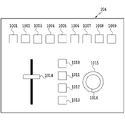
図9は、ズームコントローラ203を説明するための図である。ズームコントローラ203は、2個のつまみ901、902、4個のボタン903~906、ダイヤル907、シーソースイッチ908を備える。ズームコントローラ203において、ボタン903には、ズームのOn/Offが割り当てられ、ダイヤル907には、フォーカスが割り当てられ、シーソースイッチ908には、ズームが割り当てられる。
FIG. 9 is a diagram for explaining the
図10は、リプレイコントローラ204を説明するための図である。リプレイコントローラ204は、13個のボタン1001~1013、スライダー1014、ジョグホイール1015、フィンガーホイール1016を備える。以下、リプレイコントローラ204において、割り当てられる機能について説明する。
FIG. 10 is a diagram for explaining the
ボタン1010にはRECが割り当てられ、このボタン1010が押下されると、リプレイクリップの作成が開始され、以降において、ユーザが操作した仮想カメラのパラメータがリプレイクリップとして記録される。ボタン1011にはPLAY/PAUSEが割り当てられ、このボタン1011によりシーンの再生と一時停止が行われる。なお、一時停止されている間は、仮想カメラの時刻を停止する。さらに、ボタン1012にはREVIEWが割り当てられ、このボタン1012が押下されると、リプレイクリップの再生が開始される。
REC is assigned to a
スライダー1014は、シーン再生速度を設定するためのスライダーである。このスライダー1014によりシーン再生速度が設定されると、仮想カメラの時刻は、設定されたシーンの再生速度に応じて、変更される。ジョグホイール1015は、時刻を設定するためのものである。このジョグホイール1015により、時刻の巻き戻し、早送り等が行われる。また、フィンガーホイール1016は、フレーム単位で時刻を設定するためのものである。このフィンガーホイール1016により、時刻の巻き戻し、先送り等がフレーム単位で行われる。即ち、フィンガーホイール1016では、ジョグホイール1015よりも時刻を細かく制御することができる。
A
なお、コントローラ202、203、204において、上述で説明した以外のつまみ、ボタン、スイッチ等については、本実施形態に関係ないので、その説明を省略する。また、上述の機能以外の機能、例えば、被写界深度調整やフォーカス調整等の機能を割り当てることもできる。以下、図11~図16を参照して、各実施形態について説明する。
In the
図11は、仮想カメラの操作軸について説明するための図である。操作軸のうち、X軸703、Y軸704、Z軸705は、仮想カメラの移動操作方向に対応する。なお、X軸703、Y軸704、Z軸705は互いに直交し、Z軸705は、仮想カメラ701の姿勢によらず、常に地面702に垂直な方向である。そのため、X軸703とY軸704は、カメラの姿勢によらず、常に地面702に水平な方向である。また、X軸703とY軸704は、仮想カメラ701の姿勢によって方向が変わる。仮想カメラ701の光軸を地面702に水平な面に投影した方向がY軸704であり、仮想カメラ701の光軸に直交する方向がX軸703である。操作軸のうち、Pan軸(パン軸)706はZ軸705、Tilt軸(チルト軸)707はX軸703、Roll軸(ロール軸)708はY軸704を各々回転軸とした回転操作方向に対応する。
FIG. 11 is a diagram for explaining the operation axis of the virtual camera. Of the operation axes, an
図11(a)及び図11(b)は、仮想カメラ701をZ軸方向から見た図である。図11(a)の状態から仮想カメラをパンさせる(即ち、Z軸を回転軸として回転させる)と、図11(b)の状態になる。図11(c)及び図11(d)は、仮想カメラ701をY軸方向から見た図である。図11(c)の状態から仮想カメラをロールさせる(即ち、Y軸を回転軸として回転させる)と、図11(d)の状態になる。図11(e)及び図11(f)は、仮想カメラ701をX軸方向から見た図である。図11(e)の状態から仮想カメラをチルトさせる(即ち、X軸を回転軸として回転させる)と、図11(f)の状態になる。
11(a) and 11(b) are diagrams of the
なお、各操作軸への操作に応じて、各カメラパラメータがどのように変化するかは、図6のカメラ制御タブを選択したときのパイロットウィンドウのスライドバー513の設定による。また、操作軸とカメラパラメータの項目とは、1対1に対応するとは限らない。例えば、操作軸のX軸は仮想カメラに対して左右方向、Y軸は仮想カメラに対して前後方向であるが、カメラパラメータのX軸はグラウンドの長辺方向、Y軸はグラウンドの短辺方向としてもよい。この場合、カメラパラメータのX軸の現在値及びY軸の現在値と、操作軸のX軸の値及びY軸の値とを相互に組み合わせることによって、編集後のカメラパラメータのX軸の値及びY軸の値が決定される。具体的には、例えば、X軸をOff(編集不可)、Y軸をOn(編集可能)に設定した場合に、仮想カメラを前後方向に移動させると、グラウンドに対して斜め方向の移動であれば、カメラパラメータのX軸の値及びY軸の値は、いずれも変化する。
It should be noted that how each camera parameter changes according to the operation on each operation axis depends on the setting of the pilot
図12は、情報処理装置103の機能ブロックを示す図である。入出力部120は、上述のコントローラ202a-204、及び表示部201a-201cで構成される入出力部115により実現される機能であり、仮想カメラを制御するための複数のコントローラと、仮想カメラの状態等を表示する。
FIG. 12 is a diagram showing functional blocks of the
設定部121は、コントローラの操作に応じて、各種カメラパラメータを設定する。例えば、図6のカメラ制御タブを選択したときのパイロットウィンドウにおける各種設定や、図8の3軸コントローラの各種ボタンによる設定が該当する。なお、設定部121において設定された値は、設定記憶部122に記憶される。
The
カメラパラメータ編集部123は、入出力部120を介したユーザからの操作に応じて、カメラパラメータを編集する。具体的には、カメラパラメータ編集部123は、動画のシーンの開始時点からシーンの終了時点までの各フレームにおいて、入出力部120における操作に応じて仮想カメラの位置と視野を設定することで、カメラパラメータを編集する。カメラパラメータ記憶部124は、カメラパラメータ編集部123により編集されたカメラパラメータを、三次元オブジェクトデータの時間経過に対応付けて記憶する。
The camera
ウィンドウ制御部125は、カメラビューウィンドウ、パイロットウィンドウ、リプレイウィンドウ等の各種ウィンドウの表示制御を行う。ウィンドウ制御部125は、カメラビューウィンドウにおいて、各フレームにおけるカメラパラメータをカメラパラメータ記憶部124から読み出し、仮想視点画像生成サーバ102に渡す。さらに、ウィンドウ制御部125は、入出力部115の表示部201aのカメラビューウィンドウ内に仮想視点画像生成サーバ102が生成した仮想視点画像を表示させる。また、ウィンドウ制御部125は、パイロットウィンドウにおいて、各フレームにおけるカメラパラメータをカメラパラメータ記憶部124から読み出し、カメラパラメータの位置、姿勢に応じて仮想カメラ画角表示412を描画する。
A
図13は、情報処理装置103における処理の手順を示したフローチャートである。なお、以下において、フローチャートの説明における記号「S」は、ステップを表すものとする。即ち、ここでは、フローチャートの各処理ステップS101~ステップS114をS101~S114と略記する。
FIG. 13 is a flow chart showing the procedure of processing in the
S101において、カメラパラメータ編集部123は、カメラパラメータ記憶部124に記憶済みのカメラパラメータの中からオペレータによって指定された1つのカメラパラメータを読み出す。具体的には、図7に示すリプレイウィンドウにおいて、表示されているリプレイクリップリスト604を表示し、オペレータがリストの中から1つのリプレイクリップ605を選択(指定)する。
In S<b>101 , the camera
S102において、カメラパラメータ編集部123は、シーンの開始フレームを処理対象として設定する。S103において、カメラパラメータ編集部123は、シーンの開始フレームにおける仮想カメラパラメータを読み出す。S104においては、ウィンドウ制御部125は、カメラパラメータ記憶部124から仮想カメラパラメータを読み出して、カメラビューウィンドウ及びパイロットウィンドウを更新する。カメラビューウィンドウの更新では、仮想視点画像生成サーバ102に仮想カメラパラメータを渡し、仮想視点画像生成サーバ102において生成された仮想視点画像をカメラビューウィンドウ(カメラビュー)に表示させる。また、パイロットウィンドウの更新では、仮想カメラ画角表示412をカメラパラメータの位置、姿勢に応じて描画する。なお、S104からS114までの処理は、動画シーンのフレーム毎に実行される処理である。
In S102, the camera
S105において、カメラパラメータ編集部123は、コントローラの各操作軸に対する操作を取得する。S106において、カメラパラメータ編集部123は、カメラパラメータの最初の操作軸を処理対象とする。具体的には、例えば、X軸、Y軸、Z軸、Pan軸、Tilt軸、Roll軸、Zoom軸の順に処理を行う場合に、先ず、X軸を処理対象とする。
In S105, the camera
S107において、カメラパラメータ編集部123は、設定記憶部122に記憶されている情報(設定値)を参照して、当該操作軸(処理対象の操作軸)が編集可(On)として指定されているか否かを判定する。即ち、編集可否を判定する。情報処理装置103は、当該操作軸が編集可能として指定されていれば(107 Yes)、処理をS108に移行させ、また、当該操作軸が編集可能として指定されていなければ(S107 No)、処理をS109に移行させる。なお、S107からS112までの処理は、操作軸毎に実行される処理である。
In S107, the camera
S108において、カメラパラメータ編集部123は、S105で取得したコントローラ操作に基づいて、当該操作軸のカメラパラメータの値を導出(算出)する。他方、S109において、カメラパラメータ編集部123は、S101で指定された既存カメラパラメータの当該フレームの当該操作軸のパラメータの値をカメラパラメータ記憶部124から読み出す。
In S108, the camera
S110において、カメラパラメータ編集部123は、上述のS108で算出した値、又はS109で取得した値を、編集中のカメラパラメータの当該フレームの当該操作軸の値としてカメラパラメータ記憶部124に記憶する。
In S110, the camera
S111において、カメラパラメータ編集部123は、当該操作軸(処理対象の操作軸)が処理順序の最後の操作軸であるか否かを判定する。情報処理装置103は、当該操作軸が処理順序の最後の操作軸である場合(S111 Yes)、処理をS113に移行させ、また、当該操作軸が処理順序の最後の操作軸でない場合(S111 No)、処理をS112に移行させる。
In S111, the camera
S112において、カメラパラメータ編集部123は、その次の操作軸を処理対象として設定し、さらに、処理をS107に返す。具体的には、例えば、X軸、Y軸、Z軸、Pan軸、Tilt軸、Roll軸、Zoom軸の順に処理を行う場合に、現在の処理対象がX軸であれば、その次の処理対象(操作軸)としてY軸を新たに設定する。
In S112, the camera
S113において、カメラパラメータ編集部123は、現在のフレームがシーンの最後のフレーム(最終のフレーム)であるか否かを判定する。情報処理装置103は、最後のフレームであれば、図13に示すフローチャートの処理を終了し、最後のフレームでなければ、処理をS114に移行させる。S114において、カメラパラメータ編集部123は、現在のフレームの次のフレームを編集対象として設定し、さらに、処理をS104に返す。
In S113, the camera
図14は、カメラパラメータを編集した結果を示す図である。図14において、オブジェクト1402は軌跡1405に沿って移動しており、オペレータは、オブジェクト1402を追うように、仮想カメラ1401を軌跡1404に沿って移動させている。また、ここでは、3軸コントローラ202aにはX軸、Y軸、Z軸の操作、3軸コントローラ202bにはPan軸、Tilt軸、Roll軸の操作、ズームコントローラ203にはZoom軸の操作が割り当てられているものとする。
FIG. 14 is a diagram showing the result of editing the camera parameters. In FIG. 14, an
1回目の操作では、図6(a)に示されるように、X軸、Y軸、Z軸、Pan軸、Tilt軸、Roll軸、Zoom軸のすべてを編集可能な状態(On)にする。オペレータは、主にパイロットウィンドウのコンテキストビュー408を見ながら、片方の手で3軸コントローラ202aを操作し、X軸、Y軸、Z軸の値を調整し、仮想カメラが所望の軌跡を描くように、仮想カメラを正確に移動させる。それと同時に、オペレータは、もう片方の手で3軸コントローラ202bを操作して、Pan軸、Tilt軸、Roll軸の値を調整するが、これらの操作軸の値は、2回目の操作で正確に調整するので、1回目の操作では正確に操作(調整)されなくてもよい。また、ズームコントローラ203によるZoom軸の調整は、2回目の操作で行うので、1回目の操作では行わない。なお、1回目の操作で出力されたカメラパラメータは、図7のリプレイウィンドウのリプレイクリップ605として表示される。
In the first operation, as shown in FIG. 6A, all of the X-axis, Y-axis, Z-axis, Pan-axis, Tilt-axis, Roll-axis, and Zoom-axis are made editable (On). While mainly looking at the
1回目の操作では、図14(a)に示されるように、仮想カメラ1401の向きは所望の向き(オブジェクトへの向き)から多少ずれており、そのため、所望の構図が十分に得られていない。そこで、2回目の操作では、リプレイウィンドウのリプレイクリップ編集ボタン606を押下して、リプレイクリップ605の編集を開始する。また、2回目の操作では、図6(b)に示されるように、X軸、Y軸、Z軸を編集不可状態(Off)にする。
In the first operation, as shown in FIG. 14A, the direction of the
2回目の操作において、オペレータは、主にカメラビューウィンドウのカメラビュー301を見ながら、片方の手で3軸コントローラ202bを操作して、Pan軸、Tilt軸、Roll軸の値を正確に調整する。それと同時に、オペレータは、もう片方の手でズームコントローラ203を操作して、Zoom軸の値を正確に調整する。そして、このように調整すると、図14(b)に示されるように、仮想カメラの位置及び向きが所望の状態となる。そのため、所望の構図を得ることができる。なお、補足として、上述の操作軸のうち、さらに微調整が必要な操作軸があれば、その操作軸のみ編集可能な状態(On状態)にして、再度、同様に編集してもよい。また、編集対象とする操作軸によっては、パイロットウィンドウ(仮想カメラの位置、姿勢)、カメラビューウィンドウのいずれかを確認することで、操作することもできる。
In the second operation, the operator mainly looks at the
以上、説明したように、同時に制御する操作軸を減らし、操作軸毎に複数回に分けて操作することで、操作の負担を減らしたり、操作人数を減らしたりすることが可能になる。また、このように操作することで、各操作軸において、正確かつ容易にカメラパラメータを調整することができる。特に、上述のように、コンテキストビューを見ながらの操作と、カメラビューを見ながらの操作を分けて行うことで、オペレータが特定のビューに集中できるので、正確な操作を容易に行うことができる。また、カメラパラメータを微調整したいときに、改めてすべての操作軸の操作をやり直す必要はなく、微調整したい操作軸のみを調整(変更)できるので、調整時の負担を軽減することができる。 As described above, by reducing the number of operating axes to be controlled simultaneously and operating each operating axis in multiple steps, it is possible to reduce the burden of operation and the number of operators. In addition, by operating in this way, the camera parameters can be adjusted accurately and easily on each operating axis. In particular, as described above, by separating the operation while looking at the context view and the operation while looking at the camera view, the operator can concentrate on a specific view, making it easier to perform accurate operations. . Further, when fine adjustment of camera parameters is desired, there is no need to re-operate all the operation axes, and only the operation axis to be finely adjusted can be adjusted (changed), thereby reducing the burden during adjustment.
次に、実施形態2について、図15を参照して説明する。図15は、仮想カメラの操作軸について説明するための図である。操作軸のうち、X軸703は仮想カメラ701の側面方向、Y軸704は仮想カメラ701の正面方向(光軸方向)、Z軸705は仮想カメラ701の上面方向への移動操作方向に各々、対応し、X軸703、Y軸704、Z軸705は互いに直交する。また、操作軸のうち、Pan軸706はZ軸705、Tilt軸707はX軸703、Roll軸708はY軸704を各々回転軸とした回転操作方向に対応する。
Next,
上述の実施形態1では、3軸コントローラ202aで仮想カメラを前方に移動させる操作(即ち、Y軸方向への移動)を行うと、仮想カメラのレンズの上下方向の向き(即ち、Tilt)に依存せず、仮想カメラは、常に地面702に対して水平に移動する。他方、本実施形態(実施形態2)では、同様に3軸コントローラ202aで仮想カメラを前方に移動させる操作(即ち、Y軸方向への移動)を行うと、仮想カメラは、仮想カメラの光軸方向に移動する。そのため、仮想カメラが水平に対して下向き(即ち、Tilt値が負)であれば、仮想カメラは地面に近づくことになる(即ち、Z値が小さくなる)。また、逆に仮想カメラが水平に対して上向き(即ち、Tilt値が正)であれば、仮想カメラは地面から遠ざかることになる(即ち、Z値が大きくなる)。
In the above-described first embodiment, when an operation to move the virtual camera forward (that is, movement in the Y-axis direction) is performed by the three-
次に、実施形態3について、図16を参照して説明する。図16は、仮想カメラの操作軸について説明するための図である。操作軸のうち、X軸703、Y軸704、Z軸705は、仮想カメラの位置や姿勢に依存せず、常に一定の方向に各々、対応する。具体的には、例えば、サッカーグラウンド等の施設の場合、X軸703はグラウンドの長辺方向、Y軸704はグラウンドの短辺方向、Z軸705はグラウンド面に垂直な方向への移動操作方向に各々、対応する(即ち、各々の操作軸は施設の形状に対応する)。
Next,
なお、X軸703、Y軸704、Z軸705は互いに直交する。また、この場合、操作軸のうち、Pan軸706、Tilt軸707、Roll軸708は、上述の実施形態1、実施形態2と同様に、Z軸、X軸、Y軸の各々を回転軸とした回転操作方向に対応させることができる。但し、この例に限らず、X軸703とPan軸706、Y軸704とTilt軸707、及びZ軸705とRoll軸708が一致しないようにPan軸706、Tilt軸707、Roll軸708を設定するようにしても良い。例えば、X軸703がサッカーグラウンドの長辺方向、Y軸704がサッカーグラウンドの短辺方向を基準とした座標軸であっても、ロールやチルトの回転軸が仮想カメラの光軸の向きを基準に設定されるようにしても良い。
Note that the
次に、実施形態4について説明する。上述の実施形態では、撮影済みの画像に対してカメラパラメータを編集することで様々な視点から見たリプレイ映像を提供する例について説明したが、ここでは、撮影しながらリアルタイムにカメラパラメータを生成してライブ映像を提供する例について説明する。 Next, Embodiment 4 will be described. In the above-described embodiment, an example of providing replay videos from various viewpoints by editing the camera parameters of a captured image has been described, but here, camera parameters are generated in real time while capturing. An example in which live video is provided through the
例えば、音楽映像や演劇映像等のように、シナリオが予め決まっている場合がある。その場合、リハーサルを撮影して、リハーサル用のカメラパラメータを予め作成しておく。そして、本番において、シナリオの進行に同期させてリハーサル用のカメラパラメータを編集して、本番用のカメラパラメータを作成(生成)する。リハーサルと本番では、演者の動きに微妙な違いがあるので、それに応じて所望の構図になるように仮想カメラの向きを調整(例えば、パン、チルト、ロールのみ調整)しながら本番用のカメラパラメータを作成する。さらに、ライブ映像(ライブ画像)として放送や配信を行う。 For example, there are cases where the scenario is predetermined, such as music video or theater video. In that case, the rehearsal is filmed and the camera parameters for the rehearsal are created in advance. Then, in the actual production, the rehearsal camera parameters are edited in synchronization with the progress of the scenario to create (generate) the actual camera parameters. Since there are subtle differences in the movements of the performers between the rehearsal and the actual performance, the direction of the virtual camera is adjusted accordingly (for example, only the pan, tilt, and roll adjustments are made) while adjusting the camera parameters for the actual performance. to create In addition, broadcasting and distribution are performed as live images (live images).
次に、実施形態5について説明する。上述のように、操作軸の1つとして、リプレイコントローラ204による時間軸(より詳細には、再生速度を制御する時間軸)がある。スロー再生や一時停止等の仮想カメラ操作を含むカメラパラメータを編集する場合、リプレイコントローラ204による再生速度の調整(編集)可否を切り替えられるようにしてもよい。
Next, Embodiment 5 will be described. As described above, one of the operation axes is the time axis by the replay controller 204 (more specifically, the time axis for controlling the playback speed). When editing camera parameters including virtual camera operations such as slow playback and pause, the
編集可能にした場合、既存のカメラパラメータの再生速度によらず、リプレイコントローラ204を操作して新たに再生速度を調整しながら、さらに3軸コントローラ202やズームコントローラ203を操作して任意の操作軸を調整する。また、編集不可にした場合、既存のカメラパラメータの再生速度の変化に従って、さらに任意の操作軸を調整する。
When editing is enabled, regardless of the playback speed of the existing camera parameters, the
以上、実施形態1から実施形態5までで説明したように、仮想視点画像の生成において、仮想視点操作の自由度を向上させることで、操作上の負担を軽減することができる。また、操作軸の定義は、上述の実施形態1から実施形態5までで記載した定義に必ずしも限定されない。
As described above in
本発明は、上述の実施形態の1以上の機能を実現するプログラムを、ネットワーク又は記憶媒体を介してシステム又は装置に供給し、そのシステム又は装置のコンピュータにおける1つ以上のプロセッサがプログラムを読出し実行する処理でも実現可能である。また、1以上の機能を実現する回路(例えば、ASIC)によっても実現可能である。 The present invention supplies a program that implements one or more functions of the above-described embodiments to a system or apparatus via a network or a storage medium, and one or more processors in the computer of the system or apparatus reads and executes the program. It can also be realized by processing to It can also be implemented by a circuit (for example, ASIC) that implements one or more functions.
103 情報処理装置
121 設定部
123 カメラパラメータ編集部
124 カメラパラメータ記憶部
103
Claims (14)
前記仮想視点パラメータを変更するための第1入力情報を取得する第2取得手段と、
前記複数の仮想視点パラメータと、前記複数の仮想視点パラメータそれぞれに対して変更が可能か否かを示す制御情報とを表示する制御を行う表示制御手段と、
前記制御情報に対する第2入力情報を取得する第3取得手段と、
前記第1入力情報により変更対象となる前記複数の仮想視点パラメータのうち、前記第3取得手段により取得された前記第2入力情報に基づいて、一以上の仮想視点パラメータの変更が可能かを判定する判定手段と、
前記判定手段により変更が可能と判定された一以上の仮想視点パラメータは前記第1入力情報に基づいて変更されるように制御し、且つ、前記判定手段により変更が可能と判定されない一以上の仮想視点パラメータは前記第1入力情報に係わらず変更されないように制御する制御手段と、
を有することを特徴とする情報処理装置。 a first obtaining means for obtaining a plurality of virtual viewpoint parameters used for generating a virtual viewpoint image, the plurality of virtual viewpoint parameters including parameters representing the position of the virtual viewpoint and the line-of-sight direction from the virtual viewpoint;
a second obtaining means for obtaining first input information for changing the virtual viewpoint parameter;
display control means for controlling display of the plurality of virtual viewpoint parameters and control information indicating whether or not each of the plurality of virtual viewpoint parameters can be changed;
a third obtaining means for obtaining second input information for the control information;
Based on the second input information obtained by the third obtaining means, it is determined whether one or more virtual viewpoint parameters can be changed among the plurality of virtual viewpoint parameters to be changed by the first input information. a determination means for
One or more virtual viewpoint parameters determined to be changeable by the determination means are controlled to be changed based on the first input information , and one or more virtual viewpoint parameters not determined to be changeable by the determination means control means for controlling so that the viewpoint parameter is not changed regardless of the first input information ;
An information processing device comprising:
前記制御手段は、前記判定手段により変更が可能と判定された一以上の仮想視点パラメータが、前記設定手段により設定された変化速度に応じて変更されるように制御することを特徴とする請求項1に記載の情報処理装置。 further comprising setting means for setting a change speed with respect to an operation amount of the position of the virtual viewpoint and the line-of-sight direction from the virtual viewpoint represented by the parameters included in the plurality of virtual viewpoint parameters;
3. The control means controls such that the one or more virtual viewpoint parameters determined to be changeable by the determination means are changed according to the change speed set by the setting means. 1. The information processing device according to 1 .
前記設定手段は、前記変化速度情報に対する操作に基づいて、前記変化速度を設定することを特徴とする請求項2に記載の情報処理装置。 3. The information processing apparatus according to claim 2, wherein said setting means sets said changing speed based on an operation for said changing speed information.
前記判定手段は、前記3つのパラメータのそれぞれについて変更が可能かを判定することを特徴とする請求項1乃至5のいずれか1項に記載の情報処理装置。 The plurality of virtual viewpoint parameters includes three parameters representing a three-dimensional position of a virtual viewpoint;
6. The information processing apparatus according to claim 1, wherein said determination means determines whether each of said three parameters can be changed.
前記判定手段は、前記パン、チルト、及びロールを表すパラメータのそれぞれについて変更が可能かを判定することを特徴とする請求項1乃至6のいずれか1項に記載の情報処理装置。 the plurality of virtual viewpoint parameters include parameters representing pan, tilt, and roll in a line-of-sight direction from the virtual viewpoint;
7. The information processing apparatus according to any one of claims 1 to 6, wherein the determination means determines whether each of the parameters representing the pan, tilt, and roll can be changed.
前記仮想視点パラメータを変更するための第1入力情報を取得する第2取得工程と、
前記複数の仮想視点パラメータと、前記複数の仮想視点パラメータそれぞれに対して変更が可能か否かを示す制御情報とを表示する制御を行う表示制御工程と、
前記制御情報に対する第2入力情報を取得する第3取得工程と、
前記第1入力情報により変更対象となる前記複数の仮想視点パラメータのうち、前記第3取得工程において取得された前記第2入力情報に基づいて、一以上の仮想視点パラメータの変更が可能かを判定する判定工程と、
前記判定工程において変更が可能と判定された一以上の仮想視点パラメータは前記第1入力情報に基づいて変更されるように制御し、且つ、前記判定工程において変更が可能と判定されない一以上の仮想視点パラメータは前記第1入力情報に係わらず変更されないように制御する制御工程と
を有することを特徴とする情報処理方法。 a first obtaining step of obtaining a plurality of virtual viewpoint parameters used to generate a virtual viewpoint image, the plurality of virtual viewpoint parameters including parameters representing a position of the virtual viewpoint and a line-of-sight direction from the virtual viewpoint;
a second obtaining step of obtaining first input information for changing the virtual viewpoint parameter;
a display control step of controlling display of the plurality of virtual viewpoint parameters and control information indicating whether or not each of the plurality of virtual viewpoint parameters can be changed;
a third obtaining step of obtaining second input information for the control information;
Determining whether one or more virtual viewpoint parameters can be changed based on the second input information acquired in the third acquisition step, among the plurality of virtual viewpoint parameters to be changed by the first input information . a determination step to
One or more virtual viewpoint parameters determined to be changeable in the determining step are controlled to be changed based on the first input information , and one or more virtual viewpoint parameters not determined to be changeable in the determining step and a control step of controlling the viewpoint parameter so that it is not changed regardless of the first input information .
前記制御工程においては、前記判定工程において変更が可能と判定された一以上の仮想視点パラメータが、前記設定工程において設定された変化速度に応じて変更されるように制御することを特徴とする請求項11に記載の情報処理方法。 further comprising a setting step of setting a change speed with respect to an operation amount of the position of the virtual viewpoint and the line-of-sight direction from the virtual viewpoint represented by the parameters included in the plurality of virtual viewpoint parameters;
In the controlling step , the one or more virtual viewpoint parameters determined to be changeable in the determining step are controlled to be changed in accordance with the changing speed set in the setting step. Item 12. The information processing method according to Item 11.
前記設定工程においては、前記変化速度情報に対する操作に基づいて、前記変化速度を設定することを特徴とする請求項12に記載の情報処理方法。 In the display control step, control is performed to display change speed information indicating the change speed,
3. The information processing method according to claim 1, wherein, in said setting step, said changing speed is set based on an operation on said changing speed information .
Priority Applications (6)
| Application Number | Priority Date | Filing Date | Title |
|---|---|---|---|
| JP2018159231A JP7254464B2 (en) | 2018-08-28 | 2018-08-28 | Information processing device, control method for information processing device, and program |
| US16/536,673 US11494067B2 (en) | 2018-08-28 | 2019-08-09 | Information processing apparatus that changes viewpoint in virtual viewpoint image during playback, information processing method and storage medium |
| KR1020190102195A KR102484197B1 (en) | 2018-08-28 | 2019-08-21 | Information processing apparatus, information processing method and storage medium |
| CN201910802849.3A CN110868583A (en) | 2018-08-28 | 2019-08-28 | Information processing apparatus, information processing method, and storage medium |
| US17/960,330 US20230028531A1 (en) | 2018-08-28 | 2022-10-05 | Information processing apparatus that changes viewpoint in virtual viewpoint image during playback, information processing method and storage medium |
| JP2023055188A JP7459341B2 (en) | 2018-08-28 | 2023-03-30 | Information processing device, control method for information processing device, and program |
Applications Claiming Priority (1)
| Application Number | Priority Date | Filing Date | Title |
|---|---|---|---|
| JP2018159231A JP7254464B2 (en) | 2018-08-28 | 2018-08-28 | Information processing device, control method for information processing device, and program |
Related Child Applications (1)
| Application Number | Title | Priority Date | Filing Date |
|---|---|---|---|
| JP2023055188A Division JP7459341B2 (en) | 2018-08-28 | 2023-03-30 | Information processing device, control method for information processing device, and program |
Publications (3)
| Publication Number | Publication Date |
|---|---|
| JP2020036116A JP2020036116A (en) | 2020-03-05 |
| JP2020036116A5 JP2020036116A5 (en) | 2021-10-14 |
| JP7254464B2 true JP7254464B2 (en) | 2023-04-10 |
Family
ID=69641104
Family Applications (2)
| Application Number | Title | Priority Date | Filing Date |
|---|---|---|---|
| JP2018159231A Active JP7254464B2 (en) | 2018-08-28 | 2018-08-28 | Information processing device, control method for information processing device, and program |
| JP2023055188A Active JP7459341B2 (en) | 2018-08-28 | 2023-03-30 | Information processing device, control method for information processing device, and program |
Family Applications After (1)
| Application Number | Title | Priority Date | Filing Date |
|---|---|---|---|
| JP2023055188A Active JP7459341B2 (en) | 2018-08-28 | 2023-03-30 | Information processing device, control method for information processing device, and program |
Country Status (4)
| Country | Link |
|---|---|
| US (2) | US11494067B2 (en) |
| JP (2) | JP7254464B2 (en) |
| KR (1) | KR102484197B1 (en) |
| CN (1) | CN110868583A (en) |
Families Citing this family (4)
| Publication number | Priority date | Publication date | Assignee | Title |
|---|---|---|---|---|
| US9332285B1 (en) * | 2014-05-28 | 2016-05-03 | Lucasfilm Entertainment Company Ltd. | Switching modes of a media content item |
| EP4113453A4 (en) * | 2020-03-30 | 2023-08-30 | Sony Group Corporation | Information processing device, image processing system, and information processing method |
| USD1013705S1 (en) * | 2021-07-20 | 2024-02-06 | Splunk Inc. | Display screen or portion thereof having a graphical user interface with a time slider for a map |
| CN113794836B (en) * | 2021-09-09 | 2023-10-13 | 北京字节跳动网络技术有限公司 | Bullet time video generation method, device, system, equipment and medium |
Citations (4)
| Publication number | Priority date | Publication date | Assignee | Title |
|---|---|---|---|---|
| JP2007195091A (en) | 2006-01-23 | 2007-08-02 | Sharp Corp | Synthetic image generating system |
| JP2008502228A (en) | 2004-06-01 | 2008-01-24 | エル‐3 コミュニケーションズ コーポレイション | Method and system for performing a video flashlight |
| WO2012032996A1 (en) | 2010-09-09 | 2012-03-15 | ソニー株式会社 | Information processing device, method of processing information, and program |
| JP2018085722A (en) | 2015-05-01 | 2018-05-31 | 株式会社電通 | Free viewpoint video data distribution system |
Family Cites Families (27)
| Publication number | Priority date | Publication date | Assignee | Title |
|---|---|---|---|---|
| US7079177B2 (en) * | 1995-02-27 | 2006-07-18 | Canon Kabushiki Kaisha | Remote control system and access control method for information input apparatus with limitation by user for image access and camemremote control |
| JPH11509064A (en) * | 1995-07-10 | 1999-08-03 | サーノフ コーポレイション | Methods and systems for representing and combining images |
| US6014145A (en) * | 1997-07-07 | 2000-01-11 | International Business Machines Corporation | Navagation with optimum viewpoints in three-dimensional workspace interactive displays having three-dimensional objects with collision barriers |
| US6699127B1 (en) * | 2000-06-20 | 2004-03-02 | Nintendo Of America Inc. | Real-time replay system for video game |
| US7142209B2 (en) * | 2004-08-03 | 2006-11-28 | Microsoft Corporation | Real-time rendering system and process for interactive viewpoint video that was generated using overlapping images of a scene captured from viewpoints forming a grid |
| US7893966B2 (en) * | 2006-06-30 | 2011-02-22 | Canon Kabushiki Kaisha | Apparatus and method for controlling editing and use of image processing parameters in image processing |
| US8698735B2 (en) * | 2006-09-15 | 2014-04-15 | Lucasfilm Entertainment Company Ltd. | Constrained virtual camera control |
| US8274564B2 (en) * | 2006-10-13 | 2012-09-25 | Fuji Xerox Co., Ltd. | Interface for browsing and viewing video from multiple cameras simultaneously that conveys spatial and temporal proximity |
| CN101622648B (en) * | 2007-03-01 | 2013-05-01 | 皇家飞利浦电子股份有限公司 | Image viewing window |
| JP4226639B1 (en) | 2007-11-01 | 2009-02-18 | 株式会社コナミデジタルエンタテインメント | Image processing apparatus, image processing method, and program |
| US8355070B2 (en) * | 2008-05-23 | 2013-01-15 | Seiko Epson Corporation | Development processing device, development processing method, and storage medium of computer program for development process for developing undeveloped image data |
| US20110157155A1 (en) * | 2009-12-31 | 2011-06-30 | Disney Enterprises, Inc. | Layer management system for choreographing stereoscopic depth |
| JP5640433B2 (en) | 2010-04-07 | 2014-12-17 | 日産自動車株式会社 | Image information providing apparatus and image information providing method |
| JP2011221718A (en) | 2010-04-07 | 2011-11-04 | Sony Corp | Generation device, generation method, and program |
| BR112015029680A2 (en) * | 2013-05-31 | 2017-07-25 | Canon Kk | image collection system, image collection apparatus and control method |
| US9286717B2 (en) * | 2013-07-30 | 2016-03-15 | Hewlett-Packard Development Company, L.P. | 3D modeling motion parameters |
| WO2015025309A1 (en) * | 2013-08-20 | 2015-02-26 | Smarter Tv Ltd. | System and method for real-time processing of ultra-high resolution digital video |
| WO2015154004A1 (en) * | 2014-04-05 | 2015-10-08 | Sony Computer Entertainment America Llc | Method for efficient re-rendering objects to vary viewports and under varying rendering and rasterization parameters |
| JP6635037B2 (en) | 2014-08-01 | 2020-01-22 | ソニー株式会社 | Information processing apparatus, information processing method, and program |
| JPWO2017141511A1 (en) | 2016-02-17 | 2018-12-06 | ソニー株式会社 | Information processing apparatus, information processing system, information processing method, and program |
| JP6672075B2 (en) * | 2016-05-25 | 2020-03-25 | キヤノン株式会社 | CONTROL DEVICE, CONTROL METHOD, AND PROGRAM |
| JP6482498B2 (en) * | 2016-05-25 | 2019-03-13 | キヤノン株式会社 | Control device, control method, and program |
| JP2018085571A (en) * | 2016-11-21 | 2018-05-31 | ソニー株式会社 | Information processing apparatus, information processing method, and program |
| US10970915B2 (en) | 2017-01-06 | 2021-04-06 | Canon Kabushiki Kaisha | Virtual viewpoint setting apparatus that sets a virtual viewpoint according to a determined common image capturing area of a plurality of image capturing apparatuses, and related setting method and storage medium |
| JP6957215B2 (en) * | 2017-06-06 | 2021-11-02 | キヤノン株式会社 | Information processing equipment, information processing methods and programs |
| JP7023696B2 (en) * | 2017-12-12 | 2022-02-22 | キヤノン株式会社 | Information processing equipment, information processing methods and programs |
| JP7045218B2 (en) * | 2018-02-28 | 2022-03-31 | キヤノン株式会社 | Information processing equipment and information processing methods, programs |
-
2018
- 2018-08-28 JP JP2018159231A patent/JP7254464B2/en active Active
-
2019
- 2019-08-09 US US16/536,673 patent/US11494067B2/en active Active
- 2019-08-21 KR KR1020190102195A patent/KR102484197B1/en active IP Right Grant
- 2019-08-28 CN CN201910802849.3A patent/CN110868583A/en active Pending
-
2022
- 2022-10-05 US US17/960,330 patent/US20230028531A1/en active Pending
-
2023
- 2023-03-30 JP JP2023055188A patent/JP7459341B2/en active Active
Patent Citations (4)
| Publication number | Priority date | Publication date | Assignee | Title |
|---|---|---|---|---|
| JP2008502228A (en) | 2004-06-01 | 2008-01-24 | エル‐3 コミュニケーションズ コーポレイション | Method and system for performing a video flashlight |
| JP2007195091A (en) | 2006-01-23 | 2007-08-02 | Sharp Corp | Synthetic image generating system |
| WO2012032996A1 (en) | 2010-09-09 | 2012-03-15 | ソニー株式会社 | Information processing device, method of processing information, and program |
| JP2018085722A (en) | 2015-05-01 | 2018-05-31 | 株式会社電通 | Free viewpoint video data distribution system |
Also Published As
| Publication number | Publication date |
|---|---|
| KR20200024717A (en) | 2020-03-09 |
| US20230028531A1 (en) | 2023-01-26 |
| US20200073541A1 (en) | 2020-03-05 |
| JP2020036116A (en) | 2020-03-05 |
| JP2023083314A (en) | 2023-06-15 |
| KR102484197B1 (en) | 2023-01-03 |
| JP7459341B2 (en) | 2024-04-01 |
| US11494067B2 (en) | 2022-11-08 |
| CN110868583A (en) | 2020-03-06 |
Similar Documents
| Publication | Publication Date | Title |
|---|---|---|
| JP7254464B2 (en) | Information processing device, control method for information processing device, and program | |
| CN109889914B (en) | Video picture pushing method and device, computer equipment and storage medium | |
| US10491830B2 (en) | Information processing apparatus, control method therefor, and non-transitory computer-readable storage medium | |
| JP5861499B2 (en) | Movie presentation device | |
| KR102500615B1 (en) | Information processing device, information processing method and program | |
| JP7330683B2 (en) | Information processing device, information processing method and program | |
| JP2024050721A (en) | Information processing device, information processing method, and computer program | |
| US20200275083A1 (en) | Information processing apparatus, information processing method, and computer readable storage medium | |
| JP7472217B2 (en) | Information processing device, control method for information processing device, and program | |
| JP7458889B2 (en) | Image display device, control method, and program | |
| US20210266511A1 (en) | Information processing system, information processing method, and storage medium | |
| KR102274723B1 (en) | Device, method and computer program for editing time slice images | |
| JP2020042665A (en) | Information processing apparatus, control method thereof, and program | |
| US20200402281A1 (en) | Image processing apparatus, image processing method, and storage medium | |
| JP2020140285A (en) | Information processing device, control method of information processing device, and program | |
| US20160344946A1 (en) | Screen System | |
| JP7480377B2 (en) | Information processing device, information processing method, and program | |
| JP2019012533A (en) | Information processing apparatus, information processing method, and program | |
| JP7455524B2 (en) | Information processing device, setting method, and program | |
| CN115686295A (en) | Image processing apparatus, image processing method, and storage medium | |
| JP2021197082A (en) | Information processing apparatus, method for controlling information processing apparatus, and program | |
| JP2022060816A (en) | Information processing system, information processing method and program | |
| JP2023003765A (en) | Image generation device and control method thereof, image generation system, and program | |
| CN115412667A (en) | Information processing apparatus, information processing system, information processing method, and storage medium |
Legal Events
| Date | Code | Title | Description |
|---|---|---|---|
| A521 | Request for written amendment filed |
Free format text: JAPANESE INTERMEDIATE CODE: A523 Effective date: 20210830 |
|
| A621 | Written request for application examination |
Free format text: JAPANESE INTERMEDIATE CODE: A621 Effective date: 20210830 |
|
| A977 | Report on retrieval |
Free format text: JAPANESE INTERMEDIATE CODE: A971007 Effective date: 20220823 |
|
| A131 | Notification of reasons for refusal |
Free format text: JAPANESE INTERMEDIATE CODE: A131 Effective date: 20220830 |
|
| A521 | Request for written amendment filed |
Free format text: JAPANESE INTERMEDIATE CODE: A523 Effective date: 20221028 |
|
| TRDD | Decision of grant or rejection written | ||
| A01 | Written decision to grant a patent or to grant a registration (utility model) |
Free format text: JAPANESE INTERMEDIATE CODE: A01 Effective date: 20230228 |
|
| A61 | First payment of annual fees (during grant procedure) |
Free format text: JAPANESE INTERMEDIATE CODE: A61 Effective date: 20230329 |
|
| R151 | Written notification of patent or utility model registration |
Ref document number: 7254464 Country of ref document: JP Free format text: JAPANESE INTERMEDIATE CODE: R151 |