JP7249948B2 - Predictive Coding for 360-degree Video Based on Geometry Padding - Google Patents
Predictive Coding for 360-degree Video Based on Geometry Padding Download PDFInfo
- Publication number
- JP7249948B2 JP7249948B2 JP2019550792A JP2019550792A JP7249948B2 JP 7249948 B2 JP7249948 B2 JP 7249948B2 JP 2019550792 A JP2019550792 A JP 2019550792A JP 2019550792 A JP2019550792 A JP 2019550792A JP 7249948 B2 JP7249948 B2 JP 7249948B2
- Authority
- JP
- Japan
- Prior art keywords
- block
- face
- sub
- current block
- sample
- Prior art date
- Legal status (The legal status is an assumption and is not a legal conclusion. Google has not performed a legal analysis and makes no representation as to the accuracy of the status listed.)
- Active
Links
- 230000033001 locomotion Effects 0.000 claims description 258
- 239000013598 vector Substances 0.000 claims description 171
- 238000000034 method Methods 0.000 claims description 46
- 239000000523 sample Substances 0.000 claims description 38
- 230000002123 temporal effect Effects 0.000 claims description 37
- 239000013074 reference sample Substances 0.000 claims description 17
- PXFBZOLANLWPMH-UHFFFAOYSA-N 16-Epiaffinine Natural products C1C(C2=CC=CC=C2N2)=C2C(=O)CC2C(=CC)CN(C)C1C2CO PXFBZOLANLWPMH-UHFFFAOYSA-N 0.000 claims description 4
- 238000000638 solvent extraction Methods 0.000 description 42
- 238000004891 communication Methods 0.000 description 37
- 238000009795 derivation Methods 0.000 description 24
- 238000005516 engineering process Methods 0.000 description 24
- 230000000875 corresponding effect Effects 0.000 description 23
- 230000008569 process Effects 0.000 description 19
- 238000010586 diagram Methods 0.000 description 18
- 230000006870 function Effects 0.000 description 14
- 238000012856 packing Methods 0.000 description 12
- 238000012360 testing method Methods 0.000 description 11
- 230000005540 biological transmission Effects 0.000 description 9
- 238000007726 management method Methods 0.000 description 8
- 238000012545 processing Methods 0.000 description 8
- 230000011664 signaling Effects 0.000 description 8
- 230000002596 correlated effect Effects 0.000 description 7
- 238000001228 spectrum Methods 0.000 description 7
- 230000002146 bilateral effect Effects 0.000 description 6
- 238000007906 compression Methods 0.000 description 6
- 230000006835 compression Effects 0.000 description 6
- 239000000969 carrier Substances 0.000 description 4
- 230000002093 peripheral effect Effects 0.000 description 4
- 244000050403 Iris x germanica Species 0.000 description 3
- 239000000872 buffer Substances 0.000 description 3
- 230000001413 cellular effect Effects 0.000 description 3
- 238000013461 design Methods 0.000 description 3
- 238000009826 distribution Methods 0.000 description 3
- 238000005286 illumination Methods 0.000 description 3
- 238000013139 quantization Methods 0.000 description 3
- 238000005070 sampling Methods 0.000 description 3
- 230000009466 transformation Effects 0.000 description 3
- 238000012935 Averaging Methods 0.000 description 2
- 208000037170 Delayed Emergence from Anesthesia Diseases 0.000 description 2
- 101100172132 Mus musculus Eif3a gene Proteins 0.000 description 2
- 230000008859 change Effects 0.000 description 2
- 238000006243 chemical reaction Methods 0.000 description 2
- 230000009977 dual effect Effects 0.000 description 2
- 230000000694 effects Effects 0.000 description 2
- 229910001416 lithium ion Inorganic materials 0.000 description 2
- QELJHCBNGDEXLD-UHFFFAOYSA-N nickel zinc Chemical compound [Ni].[Zn] QELJHCBNGDEXLD-UHFFFAOYSA-N 0.000 description 2
- 238000005457 optimization Methods 0.000 description 2
- 238000005192 partition Methods 0.000 description 2
- 230000005355 Hall effect Effects 0.000 description 1
- HBBGRARXTFLTSG-UHFFFAOYSA-N Lithium ion Chemical compound [Li+] HBBGRARXTFLTSG-UHFFFAOYSA-N 0.000 description 1
- 241000700159 Rattus Species 0.000 description 1
- 230000004913 activation Effects 0.000 description 1
- 230000003044 adaptive effect Effects 0.000 description 1
- 230000002776 aggregation Effects 0.000 description 1
- 238000004220 aggregation Methods 0.000 description 1
- 238000004873 anchoring Methods 0.000 description 1
- 230000003190 augmentative effect Effects 0.000 description 1
- 230000008901 benefit Effects 0.000 description 1
- 230000000903 blocking effect Effects 0.000 description 1
- 230000003139 buffering effect Effects 0.000 description 1
- OJIJEKBXJYRIBZ-UHFFFAOYSA-N cadmium nickel Chemical compound [Ni].[Cd] OJIJEKBXJYRIBZ-UHFFFAOYSA-N 0.000 description 1
- 230000001276 controlling effect Effects 0.000 description 1
- 230000008878 coupling Effects 0.000 description 1
- 238000010168 coupling process Methods 0.000 description 1
- 238000005859 coupling reaction Methods 0.000 description 1
- 125000004122 cyclic group Chemical group 0.000 description 1
- 230000009849 deactivation Effects 0.000 description 1
- 230000001419 dependent effect Effects 0.000 description 1
- 238000002474 experimental method Methods 0.000 description 1
- 239000000446 fuel Substances 0.000 description 1
- 230000003993 interaction Effects 0.000 description 1
- 230000002045 lasting effect Effects 0.000 description 1
- 239000004973 liquid crystal related substance Substances 0.000 description 1
- 230000007774 longterm Effects 0.000 description 1
- 230000005055 memory storage Effects 0.000 description 1
- 229910052987 metal hydride Inorganic materials 0.000 description 1
- 238000010295 mobile communication Methods 0.000 description 1
- 230000006855 networking Effects 0.000 description 1
- 230000003287 optical effect Effects 0.000 description 1
- 230000000644 propagated effect Effects 0.000 description 1
- 238000000926 separation method Methods 0.000 description 1
- 230000001360 synchronised effect Effects 0.000 description 1
- 238000012549 training Methods 0.000 description 1
- 238000000411 transmission spectrum Methods 0.000 description 1
- XLYOFNOQVPJJNP-UHFFFAOYSA-N water Substances O XLYOFNOQVPJJNP-UHFFFAOYSA-N 0.000 description 1
Images


Classifications
-
- H—ELECTRICITY
- H04—ELECTRIC COMMUNICATION TECHNIQUE
- H04N—PICTORIAL COMMUNICATION, e.g. TELEVISION
- H04N19/00—Methods or arrangements for coding, decoding, compressing or decompressing digital video signals
- H04N19/50—Methods or arrangements for coding, decoding, compressing or decompressing digital video signals using predictive coding
- H04N19/503—Methods or arrangements for coding, decoding, compressing or decompressing digital video signals using predictive coding involving temporal prediction
- H04N19/51—Motion estimation or motion compensation
- H04N19/563—Motion estimation with padding, i.e. with filling of non-object values in an arbitrarily shaped picture block or region for estimation purposes
-
- H—ELECTRICITY
- H04—ELECTRIC COMMUNICATION TECHNIQUE
- H04N—PICTORIAL COMMUNICATION, e.g. TELEVISION
- H04N19/00—Methods or arrangements for coding, decoding, compressing or decompressing digital video signals
- H04N19/10—Methods or arrangements for coding, decoding, compressing or decompressing digital video signals using adaptive coding
- H04N19/102—Methods or arrangements for coding, decoding, compressing or decompressing digital video signals using adaptive coding characterised by the element, parameter or selection affected or controlled by the adaptive coding
- H04N19/103—Selection of coding mode or of prediction mode
- H04N19/105—Selection of the reference unit for prediction within a chosen coding or prediction mode, e.g. adaptive choice of position and number of pixels used for prediction
-
- H—ELECTRICITY
- H04—ELECTRIC COMMUNICATION TECHNIQUE
- H04N—PICTORIAL COMMUNICATION, e.g. TELEVISION
- H04N19/00—Methods or arrangements for coding, decoding, compressing or decompressing digital video signals
- H04N19/10—Methods or arrangements for coding, decoding, compressing or decompressing digital video signals using adaptive coding
- H04N19/169—Methods or arrangements for coding, decoding, compressing or decompressing digital video signals using adaptive coding characterised by the coding unit, i.e. the structural portion or semantic portion of the video signal being the object or the subject of the adaptive coding
- H04N19/17—Methods or arrangements for coding, decoding, compressing or decompressing digital video signals using adaptive coding characterised by the coding unit, i.e. the structural portion or semantic portion of the video signal being the object or the subject of the adaptive coding the unit being an image region, e.g. an object
- H04N19/176—Methods or arrangements for coding, decoding, compressing or decompressing digital video signals using adaptive coding characterised by the coding unit, i.e. the structural portion or semantic portion of the video signal being the object or the subject of the adaptive coding the unit being an image region, e.g. an object the region being a block, e.g. a macroblock
-
- H—ELECTRICITY
- H04—ELECTRIC COMMUNICATION TECHNIQUE
- H04N—PICTORIAL COMMUNICATION, e.g. TELEVISION
- H04N19/00—Methods or arrangements for coding, decoding, compressing or decompressing digital video signals
- H04N19/50—Methods or arrangements for coding, decoding, compressing or decompressing digital video signals using predictive coding
- H04N19/597—Methods or arrangements for coding, decoding, compressing or decompressing digital video signals using predictive coding specially adapted for multi-view video sequence encoding
Description
ビデオのための予測符号化に関する。 It relates to predictive coding for video.
関連出願の相互参照
本出願は、その内容が参照によって本明細書に組み込まれる、2017年3月17日に出願された、米国特許仮出願第62/473,105号明細書の利益を主張する。
CROSS-REFERENCE TO RELATED APPLICATIONS This application claims the benefit of U.S. Provisional Patent Application No. 62/473,105, filed March 17, 2017, the contents of which are hereby incorporated by reference. .
バーチャルリアリティ(VR)が、我々の日常生活の中に入り込み始めた。例えば、VRは、ヘルスケア、教育、ソーシャルネットワーキング、工業デザイン/トレーニング、ゲーム、映画、ショッピング、および/またはエンターテイメントを含むが、それらに限定されない分野における、多くのアプリケーションを有する。VRは、視聴者を取り囲むバーチャル環境を作成することによって、没入型の視聴体験をもたらすことができる。VRは、視聴者の本当に「そこにいる」ような感覚を生み出すことができる。ユーザの体験は、例えば、VR環境内において十分にリアルな感じを提供することに依存することができる。例えば、VRシステムは、姿勢、ジェスチャ、視線、および/または音声を通した対話をサポートすることができる。VRシステムは、触覚フィードバックをユーザに提供して、ユーザがVR世界内のオブジェクトと自然な方法で対話することを可能にすることができる。VRシステムは、360度ビデオを使用して、例えば、水平方向においては360度の角度、および/または垂直方向においては180度の角度からシーンを見る能力を、ユーザに提供することができる。VRシステムおよび/または360度ビデオは、例えば、超高精細(UHD)サービスを超える、メディア消費(medium consumption)であることができる。 Virtual reality (VR) has begun to enter our daily lives. For example, VR has many applications in fields including, but not limited to, healthcare, education, social networking, industrial design/training, gaming, movies, shopping, and/or entertainment. VR can provide an immersive viewing experience by creating a virtual environment that surrounds the viewer. VR can create the feeling of being really "there" for the viewer. The user's experience can depend, for example, on providing a sufficiently realistic feel within the VR environment. For example, a VR system may support interaction through posture, gestures, gaze, and/or voice. A VR system can provide haptic feedback to a user to allow the user to interact with objects in the VR world in a natural way. VR systems can use 360-degree video to provide users with the ability to view a scene from, for example, 360-degree angles in the horizontal direction and/or 180-degree angles in the vertical direction. VR systems and/or 360 degree video, for example, can be medium consumption, exceeding ultra high definition (UHD) services.
VRにおける360度ビデオの品質を改善する、および/またはクライアントの相互運用性のために処理チェーンを標準化する。 Improve the quality of 360 video in VR and/or standardize the processing chain for client interoperability.
ビデオ符号化システムは、360度ビデオのためのフェイスベースのサブブロック動き補償を実行して、サブブロックの1つまたは複数のサンプルを予測することができる。ビデオ符号化システムは、エンコーダ、および/またはデコーダを含むことができる。ビデオ符号化システムは、360度ビデオコンテンツを受信することができる。360度ビデオコンテンツは、複数のフェイスを含むことができる。例えば、360度ビデオコンテンツは、フレームパッキングされたピクチャ内に並べられた複数のフェイスを含むことができる。360度ビデオコンテンツは、現在ブロックを含むことができる。現在ブロックは、1つまたは複数のサブブロックを含むことができる。例えば、現在ブロックは、1つまたは複数のサブブロックに分割することができる。360度ビデオコンテンツに対して、サブブロックレベルのフェイス関連付けを実行することができる。例えば、現在ブロックのために、サブブロックモードが使用されるとき、360度ビデオコンテンツと関連付けられた、フレームパッキングされたピクチャ内のサブブロックのロケーションに基づいて、サブブロックレベルのフェイス関連付けを実行することができる。 A video coding system may perform face-based sub-block motion compensation for 360-degree video to predict one or more samples of a sub-block. A video encoding system may include an encoder and/or a decoder. A video encoding system can receive 360-degree video content. 360-degree video content can include multiple faces. For example, 360-degree video content may include multiple faces arranged in frame-packed pictures. 360-degree video content can include a current block. A current block may contain one or more sub-blocks. For example, the current block can be divided into one or more sub-blocks. Sub-block level face association can be performed for 360-degree video content. For example, for the current block, perform sub-block level face association based on the location of the sub-block in the frame-packed picture associated with the 360-degree video content when the sub-block mode is used. be able to.
例においては、サブブロックモードは、高度時間動きベクトル予測(ATMVP)モード、空間-時間動きベクトル予測(STMVP)モード、フレームレートアップコンバージョン(FRUC)モード、またはアフィンモードのうちの少なくとも1つを含むことができる。 In examples, the sub-block mode includes at least one of an advanced temporal motion vector prediction (ATMVP) mode, a spatial-temporal motion vector prediction (STMVP) mode, a frame rate upconversion (FRUC) mode, or an affine mode. be able to.
ビデオ符号化システムは、現在ブロックが、360度ビデオコンテンツと関連付けられた複数のフェイス上に配置されたサンプルを含むかどうかを決定することができる。システムは、現在ブロック内の1つまたは複数のサンプルを予測することができる。例えば、システムは、サブブロックレベルのフェイス関連付けに基づいて、現在ブロック内の1つまたは複数のサンプルを予測することができる。システムは、複数のフェイス上において、ジオメトリパディングを実行することができる。フェイスは、フェイスと関連付けられた、パディングされた領域を含むことができる。例えば、第1のフェイスは、第1のフェイスと関連付けられた、パディングされた領域を含むことができる。 A video encoding system may determine whether a current block includes samples arranged on multiple faces associated with 360-degree video content. The system can predict one or more samples in the current block. For example, the system can predict one or more samples in the current block based on sub-block level face associations. The system can perform geometry padding on multiple faces. A face can include a padded region associated with the face. For example, a first face can include a padded area associated with the first face.
例においては、現在ブロック内の第1のサブブロックについて、システムは、第1のサブブロックの第1のロケーションを識別することができる。システムは、第1のサブブロックを第1のフェイスと関連付けることができる。例えば、システムは、第1のサブブロックの識別された第1のロケーションに基づいて、第1のサブブロックを第1のフェイスと関連付けることができる。システムは、第1のサブブロック内の第1のサンプルを予測することができる。例えば、システムは、第1のサブブロックと関連付けられた第1のフェイスに基づいて、第1のサブブロック内の第1のサンプルを予測することができる。 In an example, for the first sub-block within the current block, the system can identify the first location of the first sub-block. The system can associate the first sub-block with the first face. For example, the system can associate the first sub-block with the first face based on the identified first location of the first sub-block. The system can predict the first sample in the first subblock. For example, the system can predict the first sample in the first subblock based on the first face associated with the first subblock.
システムは、第1のフェイスと関連付けられた基準サンプル(reference sample)を識別することによって、第1のサブブロックと関連付けられた第1のサンプルを予測することができる。例えば、システムは、動きベクトルを使用して、第1のフェイスと関連付けられた基準サンプルを識別することができる。システムは、識別された基準サンプルに基づいて、第1のサブブロック内の第1のサンプルを予測することができる。例えば、システムは、識別された基準サンプルを使用して、第1のサブブロック内の第1のサンプルを予測することができる。識別された基準サンプルは、第1のフェイス、または第1のフェイスのパディングされた領域と関連付けることができる。例えば、識別された基準サンプルは、第1のフェイス、または第1のフェイスのパディングされた領域内に配置することができる。 The system can predict the first sample associated with the first sub-block by identifying a reference sample associated with the first face. For example, the system can use motion vectors to identify reference samples associated with the first face. The system can predict the first sample in the first sub-block based on the identified reference samples. For example, the system can use the identified reference samples to predict the first sample in the first sub-block. The identified reference sample can be associated with the first face or a padded region of the first face. For example, the identified reference samples can be placed within the first face or a padded region of the first face.
例においては、現在ブロック内の第2のサブブロックについて、システムは、第2のサブブロックの第2のロケーションを識別することができる。システムは、第2のサブブロックを第2のフェイスと関連付けることができる。例えば、システムは、第2のサブブロックの識別された第2のロケーションに基づいて、第2のサブブロックを第2のフェイスと関連付けることができる。システムは、第2のサブブロック内の第2のサンプルを予測することができる。例えば、システムは、第2のサブブロックと関連付けられた第2のフェイスに基づいて、第2のサブブロック内の第2のサンプルを予測することができる。本明細書において説明される第2のフェイスは、第1のフェイスと異なることができる。 In an example, for a second sub-block within the current block, the system can identify a second location of the second sub-block. The system can associate a second sub-block with a second face. For example, the system can associate the second sub-block with the second face based on the identified second location of the second sub-block. The system can predict the second sample in the second subblock. For example, the system can predict the second sample in the second subblock based on the second face associated with the second subblock. The second face described herein can be different from the first face.
第1のサブブロックが、第1のフェイスと関連付けられ、第2のサブブロックが、第2のフェイスと関連付けられ、第1のフェイスが、第2のフェイスと異なる場合、システムは、第1のフェイスと関連付けられた第1の基準サンプルを使用して、第1のサンプルを予測することができ、第2のフェイスと関連付けられた第2の基準サンプルを使用して、第2のサンプルを予測することができる。 If the first sub-block is associated with the first face, the second sub-block is associated with the second face, and the first face is different from the second face, then the system A first reference sample associated with the face can be used to predict the first sample, and a second reference sample associated with the second face can be used to predict the second sample. can do.
説明的な実施形態についての詳細な説明が、様々な図を参照して、今から行われる。この説明は、可能な実施の詳細な例を提供するが、詳細は、例示的であることが意図されており、決して出願の範囲を限定しないことが留意されるべきである。 A detailed description of illustrative embodiments will now be provided with reference to various figures. While this description provides detailed examples of possible implementations, it should be noted that the details are intended to be exemplary and in no way limit the scope of the application.
VRにおける360度ビデオの品質を改善すること、および/またはクライアントの相互運用性のために処理チェーンを標準化することが、1つまたは複数のグループによって注力されてきた。例えば、全方位メディアアプリケーションフォーマットのための要件および/または技術に取り組むために、MPEG-A(マルチメディアアプリケーションフォーマット)パート19に属するアドホックグループが、ISO/IEC/MPEG内に設立された。例えば、アドホックグループ、自由視点TV(FTV)は、360度3Dビデオアプリケーションのための探索実験を実行した。FTVは、360度ビデオ(例えば、全方位ビデオ)ベースのシステム、および/またはマルチビューベースのシステムについてテストした。例えば、MPEGおよびITU-Tに属する共同ビデオ探索チーム(JVET)は、ビデオ符号化規格のためのVRを含むシーケンスをテストした。2Dビデオの符号化効率を高効率ビデオ符号化(HEVC)よりも高めるために設計された、共同探索モデル(JEM)を、360度ビデオ符号化の探索作業のために使用することができる。ビデオ圧縮技術についての予備的なコールフォーエビデンス(CfE)を公表することが計画され、そこでは、ビデオソースコンテンツのカテゴリとして、VRおよび/または360度ビデオを含むことができる。 Improving the quality of 360-degree video in VR and/or standardizing the processing chain for client interoperability has been focused by one or more groups. For example, an ad-hoc group under MPEG-A (Multimedia Application Format) Part 19 was established within ISO/IEC/MPEG to address the requirements and/or technologies for an omnidirectional media application format. For example, the ad-hoc group, Free Viewpoint TV (FTV), has performed exploratory experiments for 360-degree 3D video applications. FTV has tested 360 degree video (eg, omnidirectional video) based systems and/or multiview based systems. For example, the Joint Video Search Team (JVET) belonging to MPEG and ITU-T has tested sequences including VR for video coding standards. A joint search model (JEM), designed to increase the coding efficiency of 2D video over high efficiency video coding (HEVC), can be used for the search task of 360-degree video coding. A preliminary Call for Evidence (CfE) on video compression techniques is planned to be published, in which categories of video source content may include VR and/or 360-degree video.
キャプチャリング、処理、表示を含むVR処理チェーン内の1つもしくは複数の態様、および/またはアプリケーションの、品質および/またはユーザのエクスペリエンスを改善することができる。例えば、キャプチャリングサイド上において、VRシステムは、1つまたは複数のカメラを使用して、1つまたは複数の異なるビュー(例えば、6~12のビュー)からシーンをキャプチャすることができる。異なるビューは、一緒につなぎ合わされて、高解像度(例えば、4Kまたは8K)の360度ビデオを形成することができる。例えば、クライアントまたはユーザサイド上において、VRシステムは、計算プラットフォーム、ヘッドマウントディスプレイ(HMD)、および/またはヘッドトラッキングセンサを含むことができる。計算プラットフォームは、360度ビデオを受信および/またはデコードすることができ、表示のためのビューポートを生成することができる。ビューポートに対して、各眼ごとに1つの、2つのピクチャをレンダリングすることができる。立体視のために、2つのピクチャをHMD内に表示することができる。例えば、より良く見えるように、HMD内に表示される画像を拡大するために、レンズを使用することができる。ヘッドトラッキングセンサは、視聴者の頭部の向きを追跡し続ける(例えば、常にし続ける)ことができる。ヘッドトラッキングセンサは、向き情報をシステムに供給して、その向き用のビューポートピクチャを表示させることができる。VRシステムは、例えば、仮想世界内のオブジェクトと対話するための、視聴者用のタッチデバイス(例えば、専用タッチデバイス)を提供することができる。例においては、VRシステムは、GPUサポートを備えるワークステーションによって駆動することができる。例においては、VRシステムは、計算プラットフォーム、HMDディスプレイ、および/またはヘッドトラッキングセンサとして、スマートフォンを使用することができる。空間HMD解像度は、2160×1200であることができる。リフレッシュレートは、90Hzであることができ、視野(FOV)は、110度であることができる。ヘッドトラッキングセンサのためのサンプリングレートは、1000Hzであることができ、それは、速い(例えば、非常に速い)運動をキャプチャすることができる。VRシステムの例は、計算プラットフォームとして、スマートフォンを使用することができ、レンズおよび/またはボール紙を含むことができる。360度ビデオストリーミングサービスが、存在することができる。 The quality and/or user experience of one or more aspects within the VR processing chain, including capturing, processing, displaying, and/or applications may be improved. For example, on the capturing side, a VR system can use one or more cameras to capture a scene from one or more different views (eg, 6-12 views). Different views can be stitched together to form a high-definition (eg, 4K or 8K) 360-degree video. For example, on the client or user side, a VR system can include a computing platform, head-mounted display (HMD), and/or head-tracking sensors. A computing platform can receive and/or decode the 360-degree video and can generate a viewport for display. Two pictures can be rendered for the viewport, one for each eye. Two pictures can be displayed in the HMD for stereoscopic viewing. For example, lenses can be used to magnify the image displayed within the HMD for better viewing. A head-tracking sensor may keep track of (eg, always do) the orientation of the viewer's head. The head tracking sensor can provide orientation information to the system to display the viewport picture for that orientation. VR systems, for example, can provide touch devices (eg, dedicated touch devices) for viewers to interact with objects in the virtual world. In an example, a VR system can be driven by a workstation with GPU support. In an example, a VR system can use a smartphone as a computing platform, HMD display, and/or head tracking sensor. Spatial HMD resolution can be 2160×1200. The refresh rate can be 90 Hz and the field of view (FOV) can be 110 degrees. The sampling rate for the head tracking sensor can be 1000 Hz, which can capture fast (eg, very fast) motion. An example VR system can use a smartphone as a computing platform and can include lenses and/or cardboard. A 360-degree video streaming service may exist.
360度ビデオ配信は、球面幾何学構造を使用して、360度情報を表すことができる。例えば、1つまたは複数のカメラによってキャプチャされた、同期が取れた1つまたは複数のビューは、一体構造として、球上においてつなぎ合わせることができる。球情報は、幾何学変換プロセスを用いて、2D平面に投影することができる。投影フォーマットを説明するために、例えば、正距円筒投影(ERP)および/またはキューブマッププロジェクション(CMP)を使用することができる。 360-degree video distribution can use spherical geometry to represent 360-degree information. For example, one or more synchronized views captured by one or more cameras can be stitched together on a sphere as a monolithic structure. Spherical information can be projected onto a 2D plane using a geometric transformation process. Equirectangular projection (ERP) and/or cubemap projection (CMP), for example, can be used to describe the projection format.
ERPは、球の緯度および/または経度座標を、グリッドの水平および/または垂直座標上に(例えば、直接的に)マッピングすることができる。図1Aは、経度(φ)および緯度(θ)における球サンプリングの例を示している。図1Bは、例えば、ERPを使用して、2D平面に投影された球の例を示している。図1Cは、ERPを用いた投影ピクチャの例を示している。範囲[-π,π]内の経度φは、航空学における、偏揺れであることができ、範囲[-π/2,π/2]内の緯度θは、縦揺れであることができる。πは、円の円周の、それの直径に対する比であることができる。図1A~図1Bにおいて、(x,y,z)は、3D空間内の点の座標を表すことができ、(ue,ve)は、2D平面内の点の座標を表すことができる。ERPは、式1および/または式2に示されるように、数学的に表すことができ、
ue=(φ/(2×π)+0.5)×W (1)
ve=(0.5-θ/π)×H (2)
ここで、WおよびHは、2D平面ピクチャの幅および高さであることができる。図1Aに示されるように、球上における経度L4と緯度A1の交点である点Pは、式1および/または式2を使用して、2D平面内の(例えば、図1Bにおける)点qにマッピングすることができる。2D平面内の点qは、例えば、逆投影を介して、球上の点Pに投影し戻すことができる。図1Bにおける視野(FOV)は、X軸沿いの視野角が約110度になるように、球におけるFOVを2D平面にマッピングすることができることの例を示すことができる。
The ERP can map (eg, directly) the latitude and/or longitude coordinates of the sphere onto the horizontal and/or vertical coordinates of the grid. FIG. 1A shows an example of spherical sampling at longitude (φ) and latitude (θ). FIG. 1B shows an example of a sphere projected onto a 2D plane using ERP, for example. FIG. 1C shows an example of a projected picture using ERP. A longitude φ in the range [−π, π] can be the yaw in aeronautics, and a latitude θ in the range [−π/2, π/2] can be the pitch. π can be the ratio of the circumference of a circle to its diameter. In FIGS. 1A-1B, (x, y, z) can represent the coordinates of a point in 3D space and (ue, ve) can represent the coordinates of a point in a 2D plane. ERP can be expressed mathematically as shown in
ue=(φ/(2×π)+0.5)×W (1)
ve=(0.5−θ/π)×H (2)
where W and H can be the width and height of a 2D planar picture. As shown in FIG. 1A, point P, the intersection of longitude L4 and latitude A1 on the sphere, can be mapped to point q in the 2D plane (eg, in FIG. 1B) using
図1Cに示されるように、ERPピクチャの上部および/または下部(例えば、それぞれ北極および/または南極)は、例えば、ピクチャの中央部(例えば、赤道)と比較して、引き延ばされることができる。ERPピクチャの上部および/または下部の引き延ばしは、ERPフォーマットについては、球サンプリング密度が不均一であることができることを示すことができる。近隣ERPピクチャ間の時間相関を記述することができる動き場は、2Dビデオよりも複雑になることができる。MPEG-2、H.264、またはHEVCなどのビデオコーデックは、並進モデルを使用して、動き場を記述することができる。ビデオコーデックは、平面ERPピクチャ内の形状変化運動を表す(例えば、効率的に表す)ことができる。360度ビデオを複数のフェイスにマッピングするために、1つまたは複数の幾何学的投影フォーマットを使用することができる。 As shown in FIG. 1C, the top and/or bottom (e.g., north and/or south poles, respectively) of the ERP picture can be stretched, for example, compared to the central portion of the picture (e.g., the equator). . Stretching of the top and/or bottom of the ERP picture can indicate that for the ERP format, the spherical sampling density can be non-uniform. Motion fields that can describe temporal correlations between neighboring ERP pictures can be more complex than 2D video. MPEG-2, H. Video codecs such as H.264 or HEVC can use translational models to describe the motion field. A video codec can represent (eg, efficiently represent) shape-changing motion in planar ERP pictures. One or more geometric projection formats can be used to map a 360-degree video onto multiple faces.
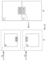
CMPは、圧縮フレンドリなフォーマットであることができる。図2Aは、CMPのための3D幾何学構造の例を示している。CMPは、6つの正方形フェイスを含むことができる。正方形フェイスには、PX、PY、PZ、NX、NY、および/またはNZというラベルを付けることができ、Pは、正を表すことができ、Nは、負を表すことができ、X、Y、Zは、軸を指すことができる。正方形フェイスには、数(例えば、0~5)を使用して、PX(0)、NX(1)、PY(2)、NY(3)、PZ(4)、および/またはNZ(5)というように、ラベルを付けることができる。内接球の半径は、1に設定することができ、1つまたは複数のフェイスの横の長さは、2に設定することができる。ビデオコーデックが、球ビデオを扱う(例えば、直接的に扱う)ように設計されていないことがあるので、CMPフォーマットの6つの正方形フェイスは、ピクチャ(例えば、単一のピクチャ)内に一緒にパッキングすることができる。近隣フェイス間の連続性を最大化するために、1つまたは複数のフェイスは、ある度だけ回転することができる。図2Bは、6つのフェイスを長方形ピクチャ内に配置するためのパッキングの例を示しており、1つまたは複数のフェイスインデックスは、フェイスの対応する回転と合致することができる向きに置かれている。例えば、図2Bに示されるように、フェイス#3およびフェイス#1は、それぞれ、反時計回りに270度および180度だけ回転することができる。他のフェイス(例えば、フェイス#0、#2、#4、および/または#5)は、回転しないことができる。図2Cは、CMPを用いた投影ピクチャの例を示している。
CMP can be a compression friendly format. FIG. 2A shows an example of 3D geometry for CMP. A CMP may contain six square faces. Square faces can be labeled PX, PY, PZ, NX, NY, and/or NZ, where P can represent positive, N can represent negative, and X, Y , Z can refer to the axis. For square faces, use numbers (eg, 0-5), PX(0), NX(1), PY(2), NY(3), PZ(4), and/or NZ(5) You can label it like so. The radius of the inscribed sphere can be set to one and the lateral length of one or more faces can be set to two. Since video codecs may not be designed to handle (e.g., directly) spherical video, the 6 square faces in CMP format are packed together in a picture (e.g., a single picture). can do. To maximize continuity between neighboring faces, one or more faces can be rotated by a degree. FIG. 2B shows an example of packing for placing six faces into a rectangular picture, where one or more face indices are oriented so that they can match the corresponding rotation of the faces. . For example, as shown in FIG. 2B,
図3は、360度ビデオシステムのための例示的なワークフローを示している。ワークフローは、1つまたは複数のカメラを使用して、全球をカバーするビデオをキャプチャすることができる。キャプチャされたビデオは、幾何学構造(例えば、ネイティブ幾何学構造)において、例えば、ERPフォーマットで、一緒につなぎ合わせることができる。幾何学構造は、ビデオコーデックを使用するエンコーディングのために、別の幾何学構造(例えば、CMPフォーマットまたは他の投影フォーマット)に変換することができる。受信機において、ビデオは、デコードすることができ、圧縮解除されたフレームは、表示のために、ジオメトリに変換することができる。ビデオは、ユーザの視野角に従ったビューポート投影を介して、レンダリングすることができ、HMDに表示することができる。 FIG. 3 shows an exemplary workflow for a 360-degree video system. A workflow can use one or more cameras to capture video covering the globe. The captured video can be stitched together in a geometric structure (eg, native geometry), eg, in ERP format. A geometry can be converted to another geometry (eg, CMP format or other projection format) for encoding using a video codec. At the receiver, the video can be decoded and the decompressed frames can be converted to geometry for display. The video can be rendered and displayed on the HMD via viewport projection according to the viewing angle of the user.
ビデオコーデックは、平面上においてキャプチャされた2Dビデオを考慮して、設計することができる。動き補償予測が、基準ピクチャの境界の外側のサンプルを使用するとき、ピクチャ境界からサンプル値をコピーすることによって、パディングを実行することができる。例えば、ピクチャ境界からサンプル値をコピーすることによって、反復パディングを実行することができる。図4Aおよび図4Bは、ERP(例えば、図4A)およびCMP(例えば、図4B)についての反復パディングによって生成された、拡張されたピクチャの例を示している。図4Aおよび図4Bにおいては、元のピクチャは、点線ボックス内にあることができ、拡張された境界は、点線ボックスの外部にあることができる。360度ビデオは、2Dビデオとは異なることができる。例えば、360度ビデオは、全球上におけるビデオ情報を含むことができ、360度ビデオは、循環的特性を有することができる。360度ビデオの循環的特性を考慮すると、360度ビデオのピクチャが含む情報は、球を包み込むことができるので、360度ビデオのピクチャ(例えば、表現のために使用される投影フォーマットは、無関係であることができる)は、境界を有さないことができる。360度ビデオ符号化のために、ジオメトリパディングを使用することができる。例えば、サンプルをパディングすることによって、および/または360度ビデオにおいて表される3D幾何学構造を考慮することによって、360度ビデオ符号化のために、ジオメトリパディングを使用することができる。例えば、360度ビデオを符号化するために適用される投影フォーマットに基づいて、1つまたは複数の異なるパディング手法を、動き補償予測のために使用することができる。 Video codecs can be designed with 2D video captured on a plane in mind. When motion compensated prediction uses samples outside the boundaries of the reference picture, padding can be performed by copying sample values from the picture boundaries. For example, repeat padding can be performed by copying sample values from picture boundaries. FIGS. 4A and 4B show examples of enhanced pictures generated by repeated padding for ERP (eg, FIG. 4A) and CMP (eg, FIG. 4B). In FIGS. 4A and 4B, the original picture can be inside the dashed box and the extended border can be outside the dashed box. 360 degree video can be different than 2D video. For example, a 360 degree video may contain video information on a full sphere, and the 360 degree video may have cyclic properties. Given the cyclical nature of 360-degree video, the information contained in a picture of 360-degree video can wrap around a sphere, so that a picture of 360-degree video (e.g., the projection format used for representation is irrelevant). ) can have no bounds. Geometry padding can be used for 360-degree video encoding. Geometry padding can be used for 360-degree video encoding, for example, by padding the samples and/or by considering the 3D geometric structure represented in the 360-degree video. For example, one or more different padding techniques may be used for motion compensated prediction based on the projection format applied to encode the 360-degree video.
ERPのためのジオメトリパディングを、経度および/または緯度を有する球上において、定義することができる。例えば、(例えば、ERPピクチャの外部の)パディングされる点(u,v)を与えられると、パディングサンプルを導出するために使用される点(u’,v’)は、1つまたは複数の式3~式5を使用して、計算することができる。
(u<0またはu≧W)かつ(0≦v<H)である場合、u’=u%W、v’=v (3)
(v<0)である場合、v’=-v-1、u’=(u+W/2)%W (4)
(v≧H)である場合、v’=2×H-1-v、u’=(u+W/2)%W (5)
ここで、WおよびHは、ERPピクチャの幅および高さであることができる。図5Aは、ERPのためのジオメトリパディングプロセスの例を示している。左および/または右境界において、A、B、C、D、E、および/またはFにおけるサンプルは、それぞれ、A’、B’、C’、D’、E’、および/またはF’におけるサンプルを用いて、パディングすることができる。上境界において、G、H、I、および/またはJにおけるサンプルは、それぞれ、G’、H’、I’、および/またはJ’におけるサンプルを用いて、パディングすることができる。下境界において、K、L、M、および/またはNにおけるサンプルは、それぞれ、K’、L’、M’、および/またはN’におけるサンプルを用いて、パディングすることができる。図5Bは、ジオメトリパディングを使用した、拡張されたERPピクチャの例を示している。図5Bにおけるジオメトリパディングは、意味あるサンプルを提供することができ、ERPピクチャ境界の外部のエリアについて、近隣サンプルの連続性を改善することができる。
Geometry padding for ERP can be defined on a sphere with longitude and/or latitude. For example, given a point (u,v) to be padded (e.g., outside an ERP picture), the point (u',v') used to derive padding samples may be one or more It can be calculated using Equations 3-5.
If (u<0 or u≧W) and (0≦v<H) then u′=u%W, v′=v (3)
if (v<0) then v′=−v−1, u′=(u+W/2)%W (4)
If (v≧H), then v′=2×H−1−v, u′=(u+W/2)%W (5)
where W and H can be the width and height of the ERP picture. FIG. 5A shows an example geometry padding process for ERP. At the left and/or right boundaries, samples at A, B, C, D, E, and/or F are samples at A', B', C', D', E', and/or F', respectively. can be used to pad. At the upper boundary, samples in G, H, I, and/or J can be padded with samples in G', H', I', and/or J', respectively. At the lower boundary, samples at K, L, M, and/or N can be padded with samples at K', L', M', and/or N', respectively. FIG. 5B shows an example of an extended ERP picture using geometry padding. Geometry padding in FIG. 5B can provide meaningful samples and improve continuity of neighboring samples for areas outside ERP picture boundaries.
投影フォーマットが、CMPであるとき、CMPのフェイスは、近隣フェイスのサンプルを現在フェイスの拡張されたエリア上に投影することを通したジオメトリパディングによって、拡張することができる。図6Aは、与えられたCMPフェイスに対して、ジオメトリパディングをどのように実行することができるかについての例を示している。図6Aにおいては、点Pは、フェイスF1上にあることができるが、フェイスF1の境界の外部にあることができる。点Oは、球の中心にあることができる。Rは、点Pに最も近い左境界点であることができ、Rは、フェイスF1の内部にあることができる。点Qは、中心点Oからの、近隣フェイスF2上における点pの投影点であることができる。ジオメトリパディングは、点Qにおけるサンプル値を使用して、点Pにおけるサンプル値を満たすように構成することができ、(例えば、反復パディングを使用して)点Rにおけるサンプル値を使用して、点Pにおけるサンプル値を満たさないことができる。図6Bは、CMPフォーマットについてのジオメトリパディングによる、拡張された6つのフェイスの例を示している。図6Bに示されるジオメトリパディングは、フェイス境界の外部の意味ある基準サンプル(reference sample)を提供することができ、および/または時間予測の効率を改善することができる。 When the projection format is CMP, a CMP face can be extended by geometry padding through projecting samples of neighboring faces onto the extended area of the current face. FIG. 6A shows an example of how geometry padding can be performed for a given CMP face. In FIG. 6A, point P can be on face F1, but can be outside the boundary of face F1. Point O can be at the center of the sphere. R may be the closest left boundary point to point P, and R may be inside face F1. Point Q may be the projection point of point p onto neighboring face F2 from center point O. Geometry padding can be configured to fill the sample values at point P using the sample values at point Q, and the sample values at point R (e.g., using repeat padding) to fill point A sample value in P may not be satisfied. FIG. 6B shows an example of 6 faces extended with geometry padding for the CMP format. The geometry padding shown in FIG. 6B can provide meaningful reference samples outside the face boundary and/or improve the efficiency of temporal prediction.
図7は、エンコーディングプロセスの例示的な図を示しており、図8は、デコーディングプロセスの例示的な図を示している。エンコーディングおよび/またはデコーディングプロセスは、例えば、HEVCエンコーディングおよび/またはデコーディングワークフローに準拠することができ、空間予測(例えば、イントラ予測)、時間予測(例えば、インター予測)、変換、量子化、エントロピ符号化、および/またはループフィルタを含む、機能ブロック(例えば、同じ機能ブロック)に基づくことができる。動き補償予測、残差変換、ループフィルタ、および/またはエントロピ符号化など、インター符号化と関連付けられた1つまたは複数のモジュールは、拡張する(例えば、さらに拡張する)ことができる。 FIG. 7 shows an exemplary diagram of the encoding process and FIG. 8 shows an exemplary diagram of the decoding process. The encoding and/or decoding processes can, for example, conform to HEVC encoding and/or decoding workflows and include spatial prediction (eg, intra-prediction), temporal prediction (eg, inter-prediction), transform, quantization, entropy It can be based on functional blocks (eg, the same functional block), including coding and/or loop filters. One or more modules associated with inter-coding, such as motion compensated prediction, residual transform, loop filter, and/or entropy coding, can be extended (eg, further extended).
図7は、例示的なブロックベースのハイブリッドビデオエンコーディングシステム600を示している。入力ビデオ信号602は、ブロックごとに処理することができる。(例えば、符号化ユニットまたはCUと呼ばれる)拡張されたブロックサイズを使用して、高解像度(例えば、1080pおよび/またはそれ以上)ビデオ信号を圧縮することができる。CUは、最大で64×64ピクセルを有することができる。CUは、予測ユニットまたはPUに区分化(partition)することができ、それらに対して、別個の予測を適用することができる。入力ビデオブロック(例えば、マクロブロック(MB)またはCU)に対して、空間予測660または時間予測662を実行することができる。空間予測(例えば、イントラ予測)は、同じビデオピクチャおよび/またはスライス内のすでに符号化された近隣ブロックからのピクセルを使用して、現在ビデオブロックを符号化することができる。空間予測は、ビデオ信号に内在する空間冗長性を低減させることができる。(例えば、インター予測または動き補償予測と呼ばれる)時間予測は、すでに符号化されたビデオピクチャからのピクセルを使用して、現在ビデオブロックを符号化することができる。時間予測は、ビデオ信号に内在する時間冗長性を低減させることができる。与えられたビデオブロックについての時間予測信号は、現在ブロックとそれの基準ブロックとの間の動きの量および/または方向を示す、動きベクトルによって伝達することができる。複数の基準ピクチャが、サポートされる場合、ビデオブロックの基準ピクチャインデックスをデコーダに伝達することができる。基準インデックスを使用して、時間予測信号が、基準ピクチャストア664内のどの基準ピクチャから来ることができるかを識別することができる。
FIG. 7 shows an exemplary block-based hybrid
空間および/または時間予測の後、エンコーダ内のモード決定680が、例えば、レート-歪み最適化に基づいて、予測モードを選択することができる。616において、現在ビデオブロックから予測ブロックを減算することができる。変換モジュール604および量子化モジュール606を使用して、予測残差を脱相関させて、ターゲットビットレートを達成することができる。量子化された残差係数を、610において逆量子化、612において逆変換して、再構成された残差を形成することができる。626において、再構成された残差を予測ブロックに加算し戻して、再構成されたビデオブロックを形成することができる。666において、デブロッキングフィルタおよび/または適応ループフィルタなどのインループフィルタを、再構成されたビデオブロックに適用することができ、その後、それは、基準ピクチャストア664内に置かれる。基準ピクチャストア664内の基準ピクチャを使用して、将来のビデオブロックを符号化することができる。出力ビデオビットストリーム620を形成することができる。符号化モード(例えば、インターもしくはイントラ符号化モード)、予測モード情報、動き情報、および/または量子化された残差係数を、エントロピ符号化ユニット608に送信して、圧縮およびパッキングを行い、ビットストリーム620を形成することができる。
After spatial and/or temporal prediction, a
図8は、例示的なブロックベースのハイブリッドビデオデコーダを示している。図8におけるデコーダは、図7におけるエンコーダに対応することができる。エントロピデコーディングユニット208において、ビデオビットストリーム202を受信し、アンパッキングし、および/またはエントロピデコードすることができる。符号化モードおよび/または予測情報を、(例えば、イントラ符号化の場合は)空間予測ユニット260に、および/または(例えば、インター符号化の場合は)時間予測ユニット262に送信することができる。空間予測ユニット260および/または時間予測ユニット262において、予測ブロックを形成することができる。残差変換係数を、逆量子化ユニット210および逆変換ユニット212に送信して、残差ブロックを再構成することができる。226において、予測ブロックと残差ブロックを加算することができる。再構成されたブロックは、インループフィルタ266を通過することができ、基準ピクチャストア264内に記憶することができる。基準ピクチャストア264内の再構成されたビデオを使用して、表示デバイスを駆動すること、および/または将来のビデオブロックを予測することができる。
FIG. 8 shows an exemplary block-based hybrid video decoder. The decoder in FIG. 8 can correspond to the encoder in FIG.
ビデオブロックは、予測方向のための動きベクトル(例えば、たかだか動きベクトル)を有することができる。サブブロックレベルの動きベクトル予測を適用できる。ブロック(例えば、大きいブロック)は、複数のサブブロック(例えば、複数の小さいサブブロック)に分割することができる。1つまたは複数(例えば、すべて)のサブブロックのための動き情報を導出することができる。高度時間動きベクトル予測(ATMVP)は、時間動きベクトル予測(TMVP)に立脚することができる。ATMVPは、符号化ブロックが、それのサブブロックの動き情報を、それの時間近隣ピクチャ(例えば、併置された(collocated)基準ピクチャ)からの複数の小さいブロックから、フェッチすることを可能にすることができる。空間-時間動きベクトル予測(STMVP)は、例えば時間近隣の動きベクトルを空間近隣のそれと平均することによって、サブブロックの動き情報を導出する(例えば再帰的に導出する)ことができる。 A video block may have a motion vector (eg, at most motion vector) for a prediction direction. Sub-block level motion vector prediction can be applied. A block (eg, a large block) can be divided into multiple sub-blocks (eg, multiple small sub-blocks). Motion information can be derived for one or more (eg, all) sub-blocks. Advanced temporal motion vector prediction (ATMVP) can build on temporal motion vector prediction (TMVP). ATMVP allows a coded block to fetch motion information for its sub-blocks from multiple small blocks from its temporal neighbor pictures (e.g., collocated reference pictures). can be done. Spatial-Temporal Motion Vector Prediction (STMVP) can derive (eg, recursively) motion information for a sub-block, eg, by averaging motion vectors of temporal neighbors with those of spatial neighbors.
ATMVPにおいては、TMVPは、ブロックが、ブロック内のサブブロックのための(例えば、動きベクトルおよび/または基準インデックスを含む)複数の動き情報を、現在ピクチャの時間近隣ピクチャの1つまたは複数(例えば、複数)のより小さいブロックから導出することを可能にすることができる。ATMVPは、本明細書において説明されるように、ブロックのサブブロックの動き情報を導出することができる。ATMVPは、時間基準ピクチャ内の(例えば、併置されたブロック(collocated block)と呼ばれることがある)現在ブロックに対応するブロックを識別することができる。選択された時間基準ピクチャは、併置されたピクチャ(collocated picture)と呼ばれることがある。ATMVPは、図9に示されるように、現在ブロックを1つまたは複数のサブブロックに分割することができ、併置されたピクチャ内の対応する小さいブロックから、サブブロック(例えば、サブブロックの各々)の動き情報を導出することができる。 In ATMVP, a block stores multiple motion information (eg, including motion vectors and/or reference indices) for sub-blocks within the block in one or more of the current picture's temporal neighbors (eg, , multiple) from smaller blocks. ATMVP can derive motion information for sub-blocks of a block as described herein. ATMVP can identify a block in a temporal reference picture that corresponds to the current block (eg, sometimes called a collocated block). The selected temporal reference picture is sometimes called a collocated picture. ATMVP can partition the current block into one or more sub-blocks, as shown in FIG. 9, and from corresponding smaller blocks in co-located pictures, sub-blocks (eg, each of the sub-blocks) motion information can be derived.
併置されたブロックおよび/または併置されたピクチャは、現在ブロックの空間近隣ブロックの動き情報によって識別することができる。ATMVP設計においては、マージ候補リスト内の利用可能な(例えば、第1の利用可能な)候補を考えることができる。図9は、ATMVPの例を示している。例えば、図9は、例えば、マージ候補リストのスキャニング順序に基づいて、現在ブロックの第1の利用可能なマージ候補として、ブロックAが識別されることを仮定することができる。ブロックAの対応する動きベクトル(例えば、MVA)、およびそれの基準インデックスを使用して、併置されたピクチャおよび/または併置されたブロックを識別することができる。併置されたピクチャ内の併置されたブロックのロケーションは、ブロックAの動きベクトル(例えば、MVA)を現在ブロックの座標に加算することによって決定することができる。 Co-located blocks and/or co-located pictures can be identified by motion information of spatial neighbors of the current block. In ATMVP design, one can consider an available (eg, first available) candidate in the merge candidate list. FIG. 9 shows an example of ATMVP. For example, FIG. 9 may assume that block A is identified as the first available merge candidate for the current block, eg, based on the scanning order of the merge candidate list. The corresponding motion vector of block A (eg, MV A ), and its reference index can be used to identify co-located pictures and/or co-located blocks. The location of the co-located block in the co-located picture can be determined by adding block A's motion vector (eg, MV A ) to the coordinates of the current block.
現在ブロック内のサブブロックについて、併置されたブロック内の(例えば、図9において矢印によって示される)対応する小さいブロックの動き情報を使用して、現在ブロック内の対応するサブブロックの動き情報を導出することができる。併置されたブロック内の小さいブロックの動き情報が、識別された後、併置されたブロック内の小さいブロックは、時間動きベクトルスケーリングを適用することができる、例えば、HEVCにおけるTMVPで、現在ブロック内の対応するサブブロックの動きベクトルおよび/または基準インデックスに変換することができる。 For sub-blocks within the current block, use the motion information of the corresponding small blocks in collocated blocks (e.g., indicated by arrows in FIG. 9) to derive motion information for the corresponding sub-blocks within the current block. can do. After the motion information of the small blocks within the collocated blocks is identified, the small blocks within the collocated blocks can apply temporal motion vector scaling, e.g. It can be converted to motion vectors and/or reference indices of corresponding sub-blocks.
STMVPにおいては、符号化ブロック内のサブブロックの動き情報は、例えば、再帰的方式で、導出することができる。図10は、STMVPの例を示している。図10は、現在ブロックが、「A」、「B」、「C」、および/または「D」などの1つまたは複数のサブブロック(例えば、4つのサブブロック)を含むことができることを仮定することができる。現在ブロックの空間近隣である、近隣の小さいブロックには、それぞれ、「a」、「b」、「c」、および/または「d」というラベルを付けることができる。サブブロック「A」についての動き導出は、空間近隣(例えば、2つの空間近隣)を識別することができる。例えば、サブブロック「A」の近隣は、上近隣「c」であることができる。小さいブロック「c」が、利用可能でない、またはイントラ符号化されていない場合、現在ブロックの上側の次の近隣の小さいブロックを、(例えば、左から右に)順番にチェックすることができる。サブブロック「A」の他の近隣は、左近隣「b」であることができる。小さいブロック「b」が、利用可能でない、またはイントラ符号化されていない場合、現在ブロックの左側の次の近隣の小さいブロックを、(例えば、上から下に)順番にチェックすることができる。空間近隣の動き情報をフェッチした後、サブブロック「A」の時間近隣の動き情報を、例えば、HEVCにおけるTMVPプロセスによって、決定することができる。利用可能な空間および/または時間近隣のいくつかまたはすべての動き情報(例えば、最大で3つ)は、平均することができ、および/またはサブブロック「A」の動き情報として使用することができる。ラスタスキャン順序に基づいて、STMVPプロセスを繰り返して、現在ビデオブロック内のいくつかまたはすべての他のサブブロックの動き情報を導出することができる。 In STMVP, motion information for sub-blocks within a coded block can be derived, for example, in a recursive manner. FIG. 10 shows an example of STMVP. FIG. 10 assumes that the current block can include one or more sub-blocks (eg, four sub-blocks) such as 'A', 'B', 'C', and/or 'D'. can do. Neighboring small blocks that are spatial neighbors of the current block can be labeled "a", "b", "c", and/or "d", respectively. Motion derivation for sub-block 'A' can identify spatial neighbors (eg, two spatial neighbors). For example, the neighbor of sub-block 'A' can be the upper neighbor 'c'. If small block 'c' is not available or not intra-coded, the next neighboring small block above the current block can be checked in order (eg, from left to right). The other neighbor of sub-block 'A' can be the left neighbor 'b'. If small block 'b' is not available or not intra-coded, the next neighboring small block to the left of the current block can be checked in order (eg, top to bottom). After fetching the spatial neighborhood motion information, the temporal neighborhood motion information of sub-block 'A' can be determined, for example, by the TMVP process in HEVC. The motion information of some or all of the available spatial and/or temporal neighborhoods (e.g., up to three) can be averaged and/or used as motion information for sub-block 'A' . Based on the raster scan order, the STMVP process can be repeated to derive motion information for some or all other sub-blocks within the current video block.
オーバーラップブロック動き補償(OBMC)を使用して、動き補償ステージにおいて、ブロッキングアーチファクトを除去することができる。例えば、ブロックの右および/または下境界を除く、1つまたは複数(例えば、すべて)のインターブロック境界に対して、OBMCを実行することができる。ビデオブロックが、サブブロックモード(例えば、ATMVPおよび/またはSTMVP)で符号化されるとき、サブブロックの境界に対して、OBMCを実行することができる。図11は、OBMCの例を示している。例えば、OBMCが、サブブロック(例えば、図11におけるサブブロック「A」)に適用されるとき、現在サブブロックの動きベクトルに加えて、(例えば、最大で4つの)近隣サブブロックの動きベクトルを使用して、現在サブブロックの予測信号を導出することができる。近隣サブブロックの動きベクトルを使用した、1つまたは複数の予測ブロックは、平均して、現在サブブロックの予測信号(例えば、最終予測信号)を生成することができる。 Overlapping block motion compensation (OBMC) can be used to remove blocking artifacts at the motion compensation stage. For example, OBMC can be performed for one or more (eg, all) inter-block boundaries, excluding the right and/or bottom boundaries of the block. When video blocks are encoded in sub-block modes (eg, ATMVP and/or STMVP), OBMC can be performed for sub-block boundaries. FIG. 11 shows an example of OBMC. For example, when OBMC is applied to a sub-block (e.g., sub-block "A" in FIG. 11), in addition to the motion vector of the current sub-block, the motion vectors of neighboring sub-blocks (e.g., up to four) are can be used to derive the prediction signal for the current sub-block. One or more prediction blocks using motion vectors of neighboring sub-blocks can be averaged to produce a prediction (eg, final prediction) of the current sub-block.
OBMCにおいて、加重平均を使用して、ブロックの予測信号を生成することができる。近隣サブブロックの動きベクトルを使用した予測信号は、PNと表記することができる。現在サブブロックの動きベクトルを使用した予測信号は、PCと表記することができる。OBMCが、適用されるとき、PNの最初および/または最後の4つの行および/または列内のサンプルは、PCにおける同じ位置のサンプルと加重平均をとることができる。加重平均が適用されるサンプルは、例えば、対応する近隣サブブロックのロケーションに従って、決定することができる。例えば、近隣サブブロックが、上近隣(例えば、図11におけるサブブロック「b」)であるとき、現在サブブロックの最初の4つの行内のサンプルを調整することができる。近隣サブブロックが、下近隣(例えば、図11におけるサブブロック「d」)であるとき、現在サブブロックの最後の4つの行内のサンプルを調整することができる。近隣サブブロックが、左近隣(例えば、図11におけるサブブロック「a」)であるとき、現在サブブロックの最初の4つの列内のサンプルを調整することができる。近隣サブブロックが、右近隣(例えば、図11におけるサブブロック「c」)であるとき、現在サブブロックの最後の4つの列内のサンプルを調整することができる。現在ブロックが、サブブロックモードで符号化されていないとき、PNの最初の4つの行および/または列のために、加重係数{1/4,1/8,1/16,1/32}を使用することができ、PCの最初の4つの行および/または列のために、加重係数{3/4,7/8,15/16,31/32}を使用することができる。現在ブロックが、サブブロックモードで符号化されているとき、PNとPCの最初の2つの行および/または列を平均することができる。PNのために、加重係数{1/4,1/8}を使用することができ、PCのために、加重係数{3/4,7/8}を使用することができる。 In OBMC, weighted averaging can be used to generate block predictions. A prediction signal using motion vectors of neighboring sub-blocks can be denoted as PN. A prediction signal using the motion vector of the current sub-block can be denoted as PC. When OBMC is applied, samples in the first and/or last four rows and/or columns of the PN can be weighted averaged with samples at the same location in the PC. The samples to which the weighted average is applied can be determined, for example, according to the locations of corresponding neighboring sub-blocks. For example, when the neighboring subblock is the upper neighbor (eg, subblock “b” in FIG. 11), the samples in the first four rows of the current subblock can be adjusted. When the neighboring sub-block is the lower neighbor (eg, sub-block 'd' in FIG. 11), the samples in the last four rows of the current sub-block can be adjusted. When the neighboring sub-block is the left neighbor (eg, sub-block “a” in FIG. 11), the samples in the first four columns of the current sub-block can be adjusted. When the neighboring subblock is the right neighbor (eg, subblock “c” in FIG. 11), the samples in the last four columns of the current subblock can be adjusted. When the current block is not coded in sub-block mode, for the first four rows and/or columns of PN, weighting factors {1/4, 1/8, 1/16, 1/32} can be used and weighting factors {3/4, 7/8, 15/16, 31/32} can be used for the first four rows and/or columns of the PC. When the current block is coded in sub-block mode, the first two rows and/or columns of PN and PC can be averaged. For PN, weighting factors {1/4, 1/8} can be used, and for PC weighting factors {3/4, 7/8} can be used.
HEVCにおいては、1つまたは複数(例えば、すべて)のインター予測パラメータ(例えば、動きベクトル、基準インデックス、および/または加重された予測パラメータ)を、エンコーダにおいて、レート-歪み(R-D)最適化によって決定することができ、デコーダに伝達することができる。符号化インター予測パラメータは、オーバヘッド(例えば、著しいオーバヘッド)を考慮することができる。シグナリングオーバヘッドは、例えば、JEMにおけるテンプレートベースの符号化を使用することによって、回避することができる。テンプレートベースの符号化は、デコーダにおいて、現在ブロックのすでに再構成された近隣サンプルであることができるテンプレートを使用して、インター予測パラメータを導出することができる。局所的照明補償(IC)は、例えば、テンプレートを使用する線形モデルに基づいて、局所的加重パラメータを導出することができ、および/または例えば、導出された加重パラメータを使用して、加重された動き補償予測を適用することができる。フレームレートアップコンバージョン(FRUC)は、デコーダにおいて、テンプレートマッチングまたはバイラテラルマッチングを使用して、動き情報を導出することができる。 In HEVC, one or more (eg, all) inter-prediction parameters (eg, motion vectors, reference indices, and/or weighted prediction parameters) are subjected to rate-distortion (RD) optimization at the encoder. can be determined by and communicated to the decoder. Coding inter-prediction parameters can account for overhead (eg, significant overhead). Signaling overhead can be avoided, for example, by using template-based encoding in JEM. Template-based coding can derive inter-prediction parameters using a template, which can be already reconstructed neighboring samples of the current block, at the decoder. Local illumination compensation (IC) can derive local weighting parameters, for example based on a linear model using a template, and/or weighted using the derived weighting parameters, for example. Motion compensated prediction can be applied. Frame rate upconversion (FRUC) can use template matching or bilateral matching at the decoder to derive motion information.
ICは、スケーリング係数「a」および/またはオフセット「b」を使用する、照明変化のための線形モデルに基づくことができる。1つまたは複数のインター符号化されたブロックに対して、ツールを適応的に有効化および/または無効化することができる。図12は、局所的ICプロセスの例を示している。図12においては、ICが、ブロックに対して適用されるとき、現在ブロックの近隣サンプル(例えば、テンプレート)と、時間基準ピクチャ内のそれらに対応する基準サンプルとの間の歪みを最小化することによって、パラメータ「a」および「b」を導出するために、最小平均2乗誤差(LMSE)を利用することができる。図12に示されるように、テンプレートは、サブサンプリング(例えば、2:1サブサンプリング)することができる。例えば、図12における影付きサンプルを使用して、「a」および「b」を導出することができる。導出されたスケーリング係数「a」およびオフセット「b」に基づいて、現在ブロックの予測サンプルを、例えば、以下のような線形モードに基づいて、調整することができ、
P(x,y)=a・Pr(x+vx,y+vy)+b
ここで、P(x,y)は、座標(x,y)における、現在ブロックの予測信号であることができ、Pr(x+vx,y+vy)は、動きベクトル(vx,vy)によって指し示される基準ブロックであることができる。
IC can be based on a linear model for illumination variation using scaling factors 'a' and/or offsets 'b'. Tools can be adaptively enabled and/or disabled for one or more inter-coded blocks. FIG. 12 shows an example of a local IC process. In FIG. 12, IC, when applied to a block, minimizes the distortion between neighboring samples (eg, template) of the current block and their corresponding reference samples in the temporal reference picture. The minimum mean squared error (LMSE) can be utilized to derive the parameters 'a' and 'b' by . As shown in FIG. 12, the template can be subsampled (eg, 2:1 subsampled). For example, the shaded samples in FIG. 12 can be used to derive 'a' and 'b'. Based on the derived scaling factor 'a' and offset 'b', the prediction samples for the current block can be adjusted, e.g., based on a linear mode as follows:
P(x, y)=a·P r (x+v x , y+v y )+b
where P(x, y) can be the prediction signal of the current block at coordinates (x, y), and P r (x+v x , y+v y ) is the motion vector (v x , v y ) can be a reference block pointed to by .
(例えば、動き情報を伝達するオーバヘッドを減じるために)インター符号化されたブロックのために、FRUCモードをサポートすることができる。FRUCモードが、有効化されているとき、ブロックの(例えば、動きベクトルおよび/または基準インデックスを含む)動き情報は、伝達されないことができる。動き情報は、デコーダサイドにおいて、例えば、テンプレートマッチングまたはバイラテラルマッチングによって、導出することができる。デコーダにおける動き導出プロセス中に、ブロックのマージ候補リスト、および/またはブロックのためにATMVPライクの予測を使用して生成された予備的な動きベクトルのセットをチェックする(例えば、最初にチェックする)ことができる。絶対差(SAD)の最小和をもたらすことができる候補を、開始点として選択することができる。開始点の周りにおいて、テンプレートマッチングまたはバイラテラルマッチングに基づいた局所探索を実行することができ、および/または最小SADをもたらす動きベクトル(MV)を、ブロック全体のためのMVとして取得することができる。動き情報は、例えば、サブブロックレベルにおいて、精緻化する(例えば、さらに精緻化する)ことができる。 FRUC mode may be supported for inter-coded blocks (eg, to reduce the overhead of conveying motion information). When FRUC mode is enabled, block motion information (eg, including motion vectors and/or reference indices) may not be conveyed. Motion information can be derived at the decoder side, eg, by template matching or bilateral matching. During the motion derivation process at the decoder, check (e.g., check first) the block's merge candidate list and/or the set of preliminary motion vectors generated using ATMVP-like prediction for the block. be able to. A candidate that can yield the smallest sum of absolute differences (SAD) can be selected as a starting point. A local search based on template matching or bilateral matching can be performed around the starting point, and/or the motion vector (MV) that yields the minimum SAD can be obtained as the MV for the entire block. . The motion information can be refined (eg, further refined), eg, at the sub-block level.
図13A~図13Bは、例示的なFRUCプロセスを示している。図13Aに示されるように、テンプレートマッチングを使用して、現在ピクチャ内のテンプレート(例えば、現在ブロックの上および/または左近隣ブロック)と、基準ピクチャ内の(例えば、テンプレートと同じサイズの)ブロックとの間においてマッチ(例えば、最良マッチ)を見つけることによって、現在ブロックの動き情報を導出することができる。図13Bにおいては、バイラテラルマッチングを使用して、2つの異なる基準ピクチャ内の、現在ブロックの動き軌道沿いの2つのブロック間においてマッチ(例えば、最良マッチ)を見つけることによって、現在ブロックの動き情報を導出することができる。バイラテラルマッチングの動き探索プロセスは、動き軌道に基づくことができる。例えば、2つの基準ブロックを指し示す動きベクトルMV0およびMV1は、現在ピクチャと、2つの基準ピクチャのうちの1つまたは複数との間の時間距離(例えば、T0およびT1)に比例することができる。 Figures 13A-13B illustrate an exemplary FRUC process. As shown in FIG. 13A, template matching is used to match a template in the current picture (eg, blocks above and/or left neighbors of the current block) with a block (eg, the same size as the template) in the reference picture. The motion information for the current block can be derived by finding a match (eg, the best match) between . In FIG. 13B, the motion information of the current block is obtained by using bilateral matching to find a match (eg, best match) between two blocks along the current block's motion trajectory in two different reference pictures. can be derived. The motion search process of bilateral matching can be based on motion trajectories. For example, motion vectors MV0 and MV1 pointing to two reference blocks may be proportional to the temporal distance (eg, T0 and T1) between the current picture and one or more of the two reference pictures.
四分木プラス二分木(QTBT)ブロック区分化構造(partitioning structure)を適用することができる。QTBT構造においては、四分木のルートノードである、符号化ツリーユニット(CTU)は、四分木方式で、区分化(partition)する(例えば、最初に区分化する)ことができ、ノードの四分木分割は、ノードが、許容される四分木サイズの最小値(MinQTSize)に到達するまで、反復することができる。四分木ノードサイズが、許容される二分木サイズの最大値(MaxBTSize)ほどの大きさである場合、四分木ノードは、水平または垂直方向において、二分木を使用して、区分化する(例えば、さらに区分化する)ことができる。二分木の分割は、二分木ノードが、許容される二分木ノードサイズの最小値(MinBTSize)、または許容される二分木深度の最大値に到達するまで、反復することができる。二分木ノードは、さらなる区分化を行わない、予測および/または変換の基本ユニットとして、使用することができる(例えば、HEVCテストモデル(HM)においては、予測ユニット(PU)および/または変換ユニット(TU)の概念が、存在しないことがある)。本明細書においては、QTBT区分化構造の例を説明することができる。CTUサイズは、128×128であることができ、MinQTSizeは、16×16であることができ、MaxBTSizeは、64×64であることができ、MinBTSizeは、4であることができる。四分木区分化をCTUに適用して(例えば、最初に適用して)、四分木リーフノードを生成することができる。四分木リーフノードサイズは、例えば、128×128から16×16までの範囲であることができる。四分木ノードが、128×128である場合、四分木ノードは、最大二分木サイズを超えるので(例えば、MaxBTSizeは、64×64であることができる)、四分木ノードは、二分木によって分割することができない。四分木ノードが、128×128でない場合、四分木ノードは、二分木によって区分化する(例えば、さらに区分化する)ことができる。四分木ノードは、二分木のルートノードであることができる。二分木深度は、0に等しいことができる。二分木区分化は、二分木深度が、MaxBTDepthに到達するまで、または二分木ノードが、MinBTSizeに等しい幅もしくは高さを有するまで、反復することができる。図14は、QTBTブロック区分化の例を示しており、実線は、四分木分割を表すことができ、点線は、二分木分割を表すことができる。 A quadtree plus binary tree (QTBT) block partitioning structure can be applied. In the QTBT structure, the coded tree unit (CTU), which is the root node of the quadtree, can be partitioned (e.g., partitioned first) in a quadtree fashion, and the nodes Quadtree splitting can be repeated until a node reaches the minimum allowed quadtree size (MinQTSize). If the quadtree node size is as large as the maximum allowed binary tree size (MaxBTSize), the quadtree node is partitioned using a binary tree in the horizontal or vertical direction ( For example, it can be further partitioned). The splitting of a binary tree can be repeated until a binary tree node reaches the minimum allowed binary tree node size (MinBTSize) or the maximum allowed binary tree depth. Binary tree nodes can be used as basic units for prediction and/or transformation without further partitioning (e.g., in the HEVC test model (HM), the prediction unit (PU) and/or the transformation unit ( The concept of TU) may not exist). An example QTBT partitioning structure may be described herein. The CTU size can be 128×128, MinQTSize can be 16×16, MaxBTSize can be 64×64, and MinBTSize can be 4. Quadtree partitioning can be applied (eg, applied first) to the CTU to generate quadtree leaf nodes. Quadtree leaf node sizes can range, for example, from 128×128 to 16×16. If a quadtree node is 128x128, the quadtree node exceeds the maximum binary tree size (eg, MaxBTSize can be 64x64), so the quadtree node is a binary tree cannot be divided by If the quadtree node is not 128×128, the quadtree node can be partitioned (eg, further partitioned) by a binary tree. A quadtree node can be the root node of a binary tree. Binary tree depth can be equal to zero. Binary tree partitioning can be repeated until the binary tree depth reaches MaxBTDepth or until a binary tree node has a width or height equal to MinBTSize. FIG. 14 shows an example of QTBT block partitioning, where the solid line can represent quadtree partitioning and the dotted line can represent binary tree partitioning.
ビデオコーデックは、同じ平面上においてキャプチャすることができる、2Dビデオ信号を検討する(例えば、それだけを検討する)ことができる。(例えば、1つまたは複数の投影フェイスを含むことができる)360度ビデオを検討するとき、1つまたは複数のフェイスは、例えば、異なる投影平面に基づいて、生成されるので、フェイス間の連続性は、壊されることがある。様々なフレームパッキングについて、フェイス間の不連続性は、増加することがある。360度ビデオ符号化の動き補償予測については、ジオメトリパディングを適用することができる。ジオメトリパディングは、フェイス境界の外部にあることができるピクチャエリアのための時間基準を提供することができる。ジオメトリパディングを使用する360度ビデオのための動き補償予測を実行することができる。 A video codec can consider (eg, only consider) a 2D video signal that can be captured on the same plane. When considering a 360-degree video (which can, for example, contain one or more projection faces), one or more faces are generated, for example, based on different projection planes, so that continuity between faces Sex can be broken. With different frame packings, discontinuities between faces may increase. For motion compensated prediction for 360-degree video coding, geometry padding can be applied. Geometry padding can provide a temporal reference for picture areas that can be outside the face boundary. Motion compensated prediction for 360-degree video using geometry padding can be performed.
近隣領域から再構成されたサンプルを使用して、インター予測パラメータ(例えば、ICのための重みおよび/もしくはオフセット、ならびに/またはFRUCのための動き情報)を導出するために、テンプレートベースの符号化(例えば、ICおよび/またはFRUC)を使用することができる。ジオメトリパディングが、テンプレートベースの符号化とともに適用される(例えば、共同で適用される)とき、複雑さが、上昇することがある。ジオメトリパディングにおいては、基準ピクチャ内のフェイスは、パディングすることができ、符号化される現在ピクチャ内のフェイスは、パディングすることができない。テンプレートベースの符号化が、使用されるとき、現在ブロックが、フェイス境界に配置される場合、ICおよび/またはFRUCによって使用されるテンプレートは、現在フェイスの外部にあることができる。ジオメトリパディングが、例として使用される場合、現在ブロックのテンプレートは、近隣フェイスからの、または現在ピクチャの外部からのものとすることができる。基準ピクチャ内のテンプレートの基準は、基準ピクチャ内の現在フェイスのパディングされた領域内にあることができる。テンプレートと、テンプレートの基準は、互いに不一致である(例えば、あまり一致しない)ことがある。図15は、ジオメトリパディングが360度ビデオ符号化に対して適用されるときの、テンプレートベースの符号化の例を示している。図15においては、(例えば、時間T0における)現在ブロックは、フェイスF1の上境界に配置することができる。現在ブロックの上テンプレートは、フェイスF0内に(例えば、異なるフェイス内に)配置することができる。ジオメトリパディングのせいで、(例えば、時間T1における)基準ブロックの上テンプレートの基準は、フェイスF1のパディングされた領域から獲得することができる。上テンプレート内のサンプルと、上テンプレートの基準内のサンプルは、強い相関を有さないことがある。 Template-based encoding to derive inter-prediction parameters (e.g., weights and/or offsets for IC and/or motion information for FRUC) using samples reconstructed from neighboring regions (eg, IC and/or FRUC) can be used. Complexity may rise when geometry padding is applied (eg, jointly applied) along with template-based encoding. In geometry padding, faces in the reference picture can be padded and faces in the current picture being encoded cannot be padded. When template-based encoding is used, the template used by the IC and/or FRUC may be outside the current face if the current block is placed on a face boundary. If geometry padding is used as an example, the current block's template can be from a neighboring face or from outside the current picture. The reference of the template in the reference picture can be within the padded area of the current face in the reference picture. The template and the criteria for the template may be inconsistent (eg, poorly matched) with each other. FIG. 15 shows an example of template-based encoding when geometry padding is applied for 360-degree video encoding. In FIG. 15, the current block (eg, at time T0) may be located at the upper boundary of face F1. The top template of the current block can be placed in face F0 (eg, in a different face). Due to geometry padding, the reference for the top template of the reference block (eg, at time T1) can be obtained from the padded region of face F1. Samples in the upper template and samples in the reference of the upper template may not have a strong correlation.
空間および/または時間近隣ブロックの動き情報は、1つまたは複数のインター符号化ツールを使用して、現在ブロックの動き情報(例えば、高度動きベクトル予測(AMVP)、TMVP、マージモード、ATMVPおよび/もしくはSTMVP)を予測すること、または現在ブロックの予測信号(例えば、OBMC)を生成することができる。現在ブロックが、フェイス境界上に配置される場合、現在ブロックの空間および/または時間近隣は、他のフェイスからフェッチすることができる。フェイス内において定義された動きベクトルを使用して、動きベクトルを予測すること、または別のフェイス内において定義されたブロックの予測信号を生成することができる。360度ビデオの1つまたは複数のフェイスは、フレームパッキングプロセス中に、回転させること、ひっくり返すこと、および/または順序を乱すことができる。異なるフェイスからの動きベクトルは、強い相関を有さないことがある。 The motion information of spatial and/or temporal neighboring blocks is combined with the motion information of the current block (e.g. Advanced Motion Vector Prediction (AMVP), TMVP, merge mode, ATMVP and/or or STMVP), or generate a prediction signal (eg, OBMC) for the current block. If the current block is positioned on a face boundary, the current block's spatial and/or temporal neighbors can be fetched from other faces. A motion vector defined within a face can be used to predict a motion vector or generate a prediction signal for a block defined within another face. One or more faces of the 360-degree video can be rotated, flipped, and/or out of order during the frame packing process. Motion vectors from different faces may not have a strong correlation.
ジオメトリパディングが、有効化されたとき、現在ブロックの基準サンプルは、現在フェイスのパディングされた領域からの(例えば常に、現在フェイスのパディングされた領域からの)ものとすることができる。ジオメトリパディングは、360度ビデオの内在的な対称特性のために、現在ブロックと相関がある(例えば、高い相関がある)ことができる基準ブロックを、パディングされた領域内において識別して、現在ブロックを予測することができることを保証することができる。QTBT区分化構造が、360度ビデオ符号化に適用される(例えば、直接的に適用される)とき、現在ピクチャ内の四分木/二分木(QT/BT)リーフノードは、1つまたは複数のフェイスにまたがることができ、1つまたは複数のフェイスからのサンプルを含むことができる(例えば、フェイス境界は、QT/BTリーフノード内に存在することができる)。フレームパッキングされたピクチャ内の近隣フェイス(例えば、2つの近隣フェイス)は、3D空間内においては、もはや隣接していないことがある。近隣フェイス(例えば、2つの近隣フェイス)境界の周りのサンプルは、異なる特性を示す(例えば、異なるオブジェクトに属している)ことがある。基準ピクチャ内の現在フェイスのパディングされた領域は、現在ブロックと強い相関を有する基準ブロックを提供することができないことがある。 When geometry padding is enabled, the reference samples of the current block can be from the padded area of the current face (eg, always from the padded area of the current face). Geometry padding identifies, within the padded region, reference blocks that can be correlated (e.g., highly correlated) with the current block due to the inherent symmetrical properties of 360-degree video. can be guaranteed to be predictable. When the QTBT partitioning structure is applied (e.g., directly applied) to 360-degree video encoding, the quadtree/binary tree (QT/BT) leaf nodes in the current picture are one or more , and may contain samples from one or more faces (eg, a face boundary may reside within a QT/BT leaf node). Neighboring faces (eg, two neighboring faces) in a frame-packed picture may no longer be adjacent in 3D space. Samples around a neighboring face (eg, two neighboring faces) boundary may exhibit different properties (eg, belong to different objects). A padded region of the current face in the reference picture may not provide a reference block that has strong correlation with the current block.
ジオメトリパディングに基づいた、360度ビデオのための動き補償予測を、実行することができる。テンプレートベースの符号化のための基準サンプル導出プロセスは、テンプレートサンプルをフェッチすることができる。例えば、テンプレートベースの符号化のための基準サンプル導出プロセスは、上および/または左近隣からテンプレートサンプルをフェッチすることができる。(例えば、上および/または左近隣からの)テンプレートサンプルは、異なるフェイスからのものとすることができ、および/または不連続な情報を含むことができる。テンプレートベースの符号化のための異なるプロセスの例は、現在フェイスの領域を超えることができるテンプレートサンプルを導出するとき、3Dジオメトリを検討することができる。 Motion compensated prediction for 360-degree video based on geometry padding can be performed. A reference sample derivation process for template-based encoding can fetch template samples. For example, a reference sample derivation process for template-based encoding can fetch template samples from the top and/or left neighbors. Template samples (eg, from top and/or left neighbors) can be from different faces and/or can contain discontinuous information. An example of a different process for template-based encoding can consider 3D geometry when deriving template samples that can exceed the region of the current face.
360度ビデオ符号化のための動き予測のために、ジオメトリベースの基準ブロック導出、および/またはジオメトリベースの動きベクトル投影を使用することができる。360度ビデオの幾何学的特性を検討することができる。 Geometry-based reference block derivation and/or geometry-based motion vector projection can be used for motion estimation for 360-degree video encoding. The geometric properties of 360 degree video can be considered.
QTBTブロック区分化は、(例えば、フェイス横断(crossing-face)QT/BTリーフノードを無効化する)ジオメトリパディングの影響を考慮して、フレームパッキングされた360度ビデオのフェイス境界において、ブロックを区分化することができる。 QTBT block partitioning partitions blocks at face boundaries in frame-packed 360-degree video, taking into account the effects of geometry padding (e.g., invalidating crossing-face QT/BT leaf nodes). can be
ビデオブロックが、フェイス境界上に配置され、テンプレートベースの符号化(例えば、ICおよび/またはFRUC)を使用して符号化される場合、ビデオブロックの1つまたは複数のテンプレートサンプルは、別のフェイスからの上および/または左近隣から獲得することができ、一方、テンプレートの基準サンプルは、時間ピクチャ内の現在フェイスのパディングされた領域から獲得することができる(例えば、図15)。不整合が、発生することがある。 When a video block is placed on a face boundary and encoded using template-based coding (eg, IC and/or FRUC), one or more template samples of the video block are mapped to another face boundary. can be obtained from the top and/or left neighbors of the template, while the template's reference samples can be obtained from the padded region of the current face in the temporal picture (eg, FIG. 15). Inconsistencies may occur.
テンプレートサンプルは、360度ビデオの3Dジオメトリに基づいて、フェッチすることができる。例えば、現在ピクチャの現在ブロックが、フェイス境界上にある場合、テンプレートサンプルは、現在フェイスの境界の外部に配置することができる。現在ピクチャの現在ブロックが、フェイス境界上にある場合、現在ブロックのテンプレートサンプルを導出するときに、3Dジオメトリ情報を適用することができる。3Dジオメトリ情報を使用して、現在ブロックのテンプレートサンプルを導出することは、現在ブロックと相関がある(例えば、より相関がある)ことができるテンプレートサンプルを提供することができる。CMPを例として使用すると、図16A~図16Cは、テンプレートベースの符号化のための異なる基準サンプル導出の例を示している。例えば、図16Aは、3D空間における、現在ブロックのロケーションと、それのテンプレートサンプルのそれとの間の例示的な関係を示している。図16Bは、左および/または上近隣(直接的な左および/または上近隣)に基づいたサンプル導出の例を示している。図16Cは、3Dジオメトリ情報に基づいた導出の例を示している。図16A~図16Cにおいては、現在ブロックは、フェイス#1の上境界に配置することができる。左テンプレートのサンプルは、図16Bおよび図16Cに示されるように、現在ブロックと同じフェイス内にあることができる、近隣ブロックの再構成されたサンプルから導出することができる。上テンプレートを導出するために、図16Cに示されるように、(例えば、幾何学投影に基づいて導出することができる)フェイス#5からのサンプルを使用することができる。フェイス#1とフェイス#5は、(例えば、図16Aに示されるように)3Dジオメトリに従えば、近隣フェイスであることができる。ジオメトリ情報(例えば、3Dジオメトリ情報)を使用して、テンプレートサンプルを導出することは、現在ブロックとの相関(例えば、より良い相関)を示すことができるテンプレートサンプルを提供することができる。ジオメトリ情報が、使用されるとき、テンプレートのサンプルは、現在ピクチャ内のデコードされた(例えば、すでにデコードされた)サンプルから導出することができる。ジオメトリパディングが、使用されるとき、また現在ピクチャが、1つまたは複数のスライスおよび/またはタイルを含む場合、ジオメトリ情報を使用して導出されたテンプレートサンプルは、テンプレートサンプルが、現在ブロックと同じスライスおよび/またはタイル内にない場合、利用可能でないことがある。スライスおよび/またはタイルは、デコードする(例えば、独立にデコードする)ことができるので、テンプレートサンプルは、利用不可能と見なすことができる。
Template samples can be fetched based on the 3D geometry of the 360 degree video. For example, if the current block of the current picture is on the face boundary, the template samples can be placed outside the boundary of the current face. If the current block of the current picture is on a face boundary, 3D geometry information can be applied when deriving the template samples for the current block. Using the 3D geometry information to derive template samples for the current block can provide template samples that can be correlated (eg, more correlated) with the current block. Using CMP as an example, FIGS. 16A-16C show examples of different reference sample derivations for template-based encoding. For example, FIG. 16A shows an exemplary relationship between the location of the current block and that of its template samples in 3D space. FIG. 16B shows an example of sample derivation based on left and/or top neighbors (direct left and/or top neighbors). FIG. 16C shows an example of derivation based on 3D geometry information. In Figures 16A-16C, the current block may be located at the upper boundary of
現在ブロックのテンプレート基準サンプルは、例えば、3Dジオメトリ情報に基づいた幾何学的近隣から、導出することができる。ジオメトリ情報(例えば、3Dジオメトリ情報)を使用することは、テンプレートのサンプルと現在ブロックとの間の相関を最大化することができる。ジオメトリ情報を使用するとき、デコーダは、先に再構成されたフェイスのサンプルを維持する(例えば、一時的に維持する)ことができる。ラインバッファサイズを低減させるために、テンプレートサンプルが、現在フェイスの境界の外部にある場合、テンプレートサンプルは、無効化することができる(例えば、利用不可能と見なすことができる)。例えば、現在ブロックが、フェイス境界上にある場合、テンプレートベースの符号化ツールは、無効化することができる。フェイス境界上のブロックの数は、小さいものであることができるので、テンプレートベースの符号化ツールを無効化することは、限定的な性能しか影響を伴わずに、ラインバッファサイズを低減させることができる。図16A~図16Cに示されるように、使用されるフレームパッキングに応じて、フレームパッキングされたレイアウト内のいくつかの近隣フェイスは、3Dジオメトリに基づいて、隣接していることができる。例えば、フェイス#4とフェイス#5、および/またはフェイス#3とフェイス#1は、フレームパッキングされたフォーマットにおいて近隣であること、および/または3D空間において近隣であることができる。空間近隣から導出されたサンプルは、テンプレートベースの符号化のための候補(例えば、良好な候補)を提供することができる。テンプレートサンプルが、幾何学的に現在フェイスに対して近隣でないことができる近隣フェイスからのものである場合、テンプレートサンプルは、無効化することができる。例えば、テンプレートが、現在フェイスからのものである場合、または幾何学的に近隣フェイスからのものである場合、テンプレートは、テンプレートベースの符号化のために有効である(例えば、利用可能である)と見なすことができる。左CTUのサンプル、および/または上CTU行のサンプルは、キャッシュされないことができるので、本明細書において説明されるテンプレートベースの符号化は、より少ないラインバッファを必要とすることができる。
Template reference samples for the current block can be derived, for example, from geometric neighborhoods based on 3D geometry information. Using geometry information (eg, 3D geometry information) can maximize the correlation between the samples of the template and the current block. When using geometry information, the decoder can retain (eg, temporarily retain) samples of previously reconstructed faces. To reduce the line buffer size, template samples can be invalidated (eg, considered unavailable) if they are currently outside the bounds of the face. For example, template-based coding tools can be disabled if the current block is on a face boundary. Since the number of blocks on the face boundary can be small, disabling template-based encoding tools can reduce line buffer size with only limited performance impact. can. As shown in FIGS. 16A-16C, depending on the frame packing used, some neighboring faces in the frame-packed layout may be adjacent based on their 3D geometry. For example,
図17は、CMP投影フォーマットに基づいた、接続された近隣フェイスからのテンプレートサンプルを使用するブロックと、接続されていない近隣フェイスからのテンプレートサンプルを使用するブロックの例を示している。図17においては、点々のあるブロック1704は、現在フェイスと3D空間における幾何学的な近隣フェイスとの間の境界上に配置された符号化ブロックを表すことができる。点々のあるブロックの左および上テンプレート内のサンプルは、利用可能としてマークすることができる。図17における線のあるブロック1702は、現在フェイスと3D空間における幾何学的な不連続フェイスとの間の境界上に配置された符号化ブロックを表すことができる。線のあるブロックの(例えば、上テンプレートではなく)左テンプレートのサンプルは、テンプレートベースのために利用可能であることができる。
FIG. 17 shows an example of a block using template samples from connected neighboring faces and a block using template samples from unconnected neighboring faces based on the CMP projection format. In FIG. 17, a
エンコーダおよび/またはデコーダは、テンプレートベースの符号化のために、テンプレートピクセルのロケーションおよび/または向きを決定することができる。 An encoder and/or decoder can determine the location and/or orientation of template pixels for template-based encoding.
マルチフェイス投影フォーマットの第1のフェイス内に配置された現在ブロックについて、現在ブロックのテンプレートが、第1のフェイス内に存在するかどうかを決定することができる。現在ブロックのテンプレートが、第1のフェイス内に存在しない場合、現在ブロックのテンプレートのロケーションおよび/または向きを、決定することができる。例えば、マルチフェイス投影フォーマットのフェイス間の幾何学的関係を使用して、第2のフェイスを識別することができる。第2のフェイスは、第1のフェイスと異なることができ、現在ブロックのテンプレートは、第2のフェイス内に存在することができる。フェイスパッキング関係を使用して、マルチフェイス投影フォーマット内の第2のフェイス内の現在ブロックのテンプレートのロケーションおよび/または向きを識別することができる。テンプレートベースの符号化に従って、現在ブロックの予測のためのテンプレートを使用することができる。 For a current block placed in a first face of a multi-face projection format, it can be determined whether a template for the current block exists in the first face. If the template of the current block is not within the first face, the location and/or orientation of the template of the current block can be determined. For example, geometric relationships between faces in the multi-face projection format can be used to identify the second face. The second face can be different from the first face, and the template for the current block can reside within the second face. A face-packing relationship can be used to identify the location and/or orientation of the current block's template in the second face in the multi-face projection format. According to template-based coding, a template can be used for prediction of the current block.
テンプレートベースの符号化は、現在フレーム内の、または符号化された(例えば、すでにエンコードおよび/またはデコードされた)基準フレーム内の現在ブロックのロケーションに隣接することができる、符号化された(例えば、すでにエンコードおよび/またはデコードされた)ピクセルの1つまたは複数のテンプレートと関連付けることができる、IC、FRUC、または他の予測であることができる。テンプレートは、現在ブロックの上に配置された「上」テンプレート、現在ブロックの左に配置された「左」テンプレート、現在ブロックの下に配置された「下」テンプレート、現在ブロックの右に配置された「右」テンプレート、または関連ロケーションにおいて現在ブロックに隣接するように定義された他のテンプレートであることができる。マルチフェイス投影フォーマットは、キューブマップフォーマット、8面体フォーマット、20面体フォーマット、または圧縮のためにフェイスを2Dフレーム内にパッキングすることができる他のマルチフェイス投影フォーマットであることができる。幾何学的関係は、図16Aに示されるような、3Dジオメトリにおけるフェイス間の関係を定義することができる。フェイスパッキング関係は、フェイスパッキングされた2D投影フォーマット内の1つまたは複数のフェイスのロケーションおよび/または向きを指定することができる。例えば、パッキングされたフェイスの並びを、図16Cに示すことができる。 Template-based encoding can be adjacent to the location of the current block in the current frame or in an encoded (eg, already encoded and/or decoded) reference frame (e.g., , FRUC, or other prediction that can be associated with one or more templates of pixels (already encoded and/or decoded). The templates are: "top" template positioned above the current block, "left" template positioned to the left of the current block, "bottom" template positioned below the current block, and "bottom" template positioned to the right of the current block. It can be the "right" template, or other template defined to be adjacent to the current block at the relevant location. The multi-face projection format can be a cubemap format, an octahedron format, an icosahedron format, or any other multi-face projection format that can pack faces into a 2D frame for compression. Geometric relationships can define relationships between faces in 3D geometry, such as shown in FIG. 16A. A face-packing relationship may specify the location and/or orientation of one or more faces within a face-packed 2D projection format. For example, a packed array of faces can be shown in FIG. 16C.
ジオメトリパディングが、360度ビデオを符号化するために使用されるときに、ブロックが、現在フェイスの領域の外部にあるサンプルを参照する場合、基準サンプル値を生成することができる。例えば、基準サンプル値は、例えば、3Dジオメトリを使用して、近隣フェイスの対応するサンプルを現在フェイス内に投影することによって、生成することができる。フェイス内の1つまたは複数のブロックの動きベクトルは、基準ピクチャ内のフェイスのパディングされた領域を超えることができる基準サンプルを参照することができない。空間および/または時間近隣ブロックの動き情報を使用して、動き情報を予測すること、または現在ブロックの動き補償信号を生成することができる。現在ブロックの位置が、1つまたは複数のフェイス境界上に配置される場合、現在ブロックの空間および/または時間近隣は、近隣フェイスからのものとすることができる。現在フェイスと、それの近隣フェイスが、3D空間において隣接していない場合、現在ブロックとそれの空間および/または時間近隣の動きは、相関(例えば、明らかな相関)を有さないことがある。動きベクトルは、3Dジオメトリに基づいて、予測することができる。 When geometry padding is used to encode 360-degree video, a reference sample value can be generated if a block references samples outside the region of the current face. For example, reference sample values can be generated by projecting corresponding samples of neighboring faces into the current face using, for example, 3D geometry. A motion vector for one or more blocks in a face cannot reference reference samples that can extend beyond the padded area of the face in the reference picture. Motion information of spatial and/or temporal neighboring blocks can be used to predict motion information or generate a motion compensated signal for the current block. If the current block's position is located on one or more face boundaries, the current block's spatial and/or temporal neighbors may be from neighboring faces. If the current face and its neighboring faces are not adjacent in 3D space, the motion of the current block and its spatial and/or temporal neighbors may have no correlation (eg, obvious correlation). Motion vectors can be predicted based on 3D geometry.
基準ブロックの動きベクトルを導出するために、3Dジオメトリを適用することができる。例えば、基準ブロックの動きベクトルは、それの位置が、現在ブロックが属するフェイスの外部にあるとき、3Dジオメトリに基づいて、導出することができる。3Dジオメトリに基づいた動きベクトル予測は、フェイス境界上に配置することができるブロックのための効率的な動きベクトル予測子(predictor)を提供することができる。図18は、マージモードを使用するジオメトリベースの動き予測の例を示している。図18に示されるように、5つの空間近隣候補(例えば、左(L)、上(A)、左下(BL)、右上(AR)、および左上(AL))を使用することができる。現在ブロックは、フェイス#1内に配置され、フェイス#1とフェイス#3は、3Dジオメトリにおいて近隣フェイスであるので、対応する左および左下近隣を、フェイス#3から導出することができる(例えば、3Dジオメトリ情報を使用して導出された近隣ブロックは、Lおよび/またはBL候補について同じであることができる)。上、右上、および/または左上近隣については、(例えば、3Dジオメトリに従えば、フェイス#1に対する隣接フェイスである)フェイス#5のフェイス境界上のブロック、すなわち、それぞれ、図18におけるブロックA’、AR’、およびAL’を使用することができる。フェイス#1とフェイス#5との間の3D連続性を与えられると、ジオメトリベースの導出は、現在ブロックの動きベクトルと相関があることができる、動きベクトル予測子を提供することができる。フレームパッキングプロセス中に、1つまたは複数のフェイスは、回転させることができる(例えば、図18におけるフェイス#1および/またはフェイス#3)。対応する基準ブロックが、異なるフェイスから導出されるとき、動きベクトルは、回転させることができる。例えば、図18においては、フェイス#1は、フレームパッキングされたCMPピクチャにおいて、180度だけ回転させる(例えば、反時計回りに回転させる)ことができるので、フェイス#5内のA’、AR’、および/またはAL’から導出される動きベクトルは、180度だけ回転させて(例えば、反時計回りに回転させて)、フェイス#1内の現在ブロックの動きベクトルの座標と合わせることができる。
3D geometry can be applied to derive the motion vectors of the reference blocks. For example, the motion vector of a reference block can be derived based on the 3D geometry when its position is outside the face to which the current block belongs. Motion vector prediction based on 3D geometry can provide efficient motion vector predictors for blocks that can be placed on face boundaries. FIG. 18 shows an example of geometry-based motion estimation using merge mode. As shown in FIG. 18, five spatial neighbor candidates (eg, left (L), top (A), bottom left (BL), top right (AR), and top left (AL)) can be used. Since the current block is located within
例えば、図18においては、フェイス#1内の現在ブロックの動きベクトルを予測するために、エンコーダおよび/またはデコーダは、フェイス#5の右境界上のブロックの1つまたは複数(例えば、すべて)の動き情報を維持することができる。対応する近隣ブロックが、現在フェイスの境界の外部にある場合、動きベクトル候補は、無効化することができる(例えば、動きベクトル候補は、利用不可能と見なすことができる)。例えば、図18における5つの動きベクトル候補(例えば、L、A、BL、AR、および/またはAL)のうちの1つまたは複数は、動きベクトル候補が、現在ブロックと同じフェイス内にあることができないので、マージプロセスのためには無効として扱うことができる。動きベクトル候補が、3D空間において現在フェイスに幾何学的に隣接することができない近隣フェイスからのものである場合、動きベクトル候補は、無効化することができる。例えば、基準ブロックが、現在フェイスに幾何学的に近隣であるフェイス内に配置された場合、対応する動きは、現在ブロックの動きベクトル予測のために有効と見なすことができる。例えば、図18においては、現在ブロックの動きベクトルを予測するとき、基準ブロックLおよび/またはBLは、有効な候補と見なすことができ、一方、基準ブロックA、AR、および/またはALは、無効な候補と見なすことができる。
For example, in FIG. 18, to predict the motion vector of the current block in
エンコーダおよび/またはデコーダは、動きベクトルを予測において使用する動きベクトル候補のロケーションおよび/または向きを決定することができる。現在ブロックについて、動きベクトル候補を提供するブロックが、現在ブロックと同じフェイス内に存在するかどうかを決定することができる。動きベクトル候補を提供するブロックが、現在ブロックと同じフェイス内に存在しない場合、動きベクトル候補を提供するブロックのロケーションおよび/または向きは、例えば、幾何学的関係に基づいて、決定することができる。マルチフェイス投影フォーマットのフェイス間の幾何学的関係を使用して、動きベクトル候補を提供するブロックが存在する(例えば、現在ブロックを含むフェイスと異なる)フェイスを識別することができる。フェイスパッキング関係を使用して、マルチフェイス投影フォーマットにおける識別されたフェイス内の動きベクトル候補を提供するブロックのロケーションおよび/または向きを識別することができる。動きベクトル候補は、ブロックの識別されたロケーションおよび/または向きに基づいて、取り出すことができる。取り出された動きベクトル候補は、動きベクトル予測に従って、現在ブロックの動きを予測することができる。 An encoder and/or decoder can determine the location and/or orientation of candidate motion vectors that use the motion vectors in prediction. For the current block, it can be determined whether the block providing motion vector candidates is in the same face as the current block. If the block providing the motion vector candidate is not in the same face as the current block, the location and/or orientation of the block providing the motion vector candidate can be determined, for example, based on geometric relationships. . Geometric relationships between the faces of the multi-face projection format can be used to identify the face (eg, different from the face containing the current block) in which there are blocks that provide motion vector candidates. A face-packing relationship can be used to identify the location and/or orientation of blocks that provide motion vector candidates within an identified face in the multi-face projection format. Motion vector candidates can be retrieved based on the identified locations and/or orientations of the blocks. The retrieved motion vector candidates can predict the motion of the current block according to motion vector prediction.
動きベクトル候補を提供するブロックが、現在ブロックと同じフェイス内に存在するかどうかを決定することができる。例えば、動きベクトル候補を提供するブロックが、現在フェイスと同じフェイス内に存在するかどうかを決定することは、現在ブロックの位置に関する動きベクトル候補を提供するブロックの位置を使用して、決定することができる。そのような関連する位置(例えば、AL、A、AR、L、および/またはBL)の例を、図18に示すことができる。現在ブロックの動きの予測において、1つまたは複数の候補動きベクトルを使用することができる。1つまたは複数の候補動きベクトルが、様々な関連する位置に配置されるとき、本明細書において説明される動きベクトル予測において使用する、動きベクトル候補のロケーションおよび/または向きの決定を、関連する1つまたは複数の候補動きベクトル位置について繰り返すことができる。動きベクトル候補を提供するブロックの識別された向きが、マルチフェイス投影フォーマット内の現在ブロックの向きと異なる場合、動きベクトルを回転させて、向きの違いを補償することができる。マルチフェイス投影フォーマットは、キューブマップフォーマット、8面体フォーマット、20面体フォーマット、または圧縮のためにフェイスを2Dフレーム内にパッキングすることができる他のマルチフェイス投影フォーマットであることができる。幾何学的関係は、図18の左側に描かれた3Dキューブに示されるような、3Dジオメトリにおけるフェイス間の関係を定義することができる。フェイスパッキング関係は、図18の右側のフェイスの並びに示されるような、フェイスパッキングされた2D投影フォーマット内の1つまたは複数のフェイスのロケーションおよび/または向きを指定することができる。 It can be determined whether the block providing motion vector candidates is in the same face as the current block. For example, determining whether the block providing the motion vector candidate is in the same face as the current face may be determined using the position of the block providing the motion vector candidate relative to the position of the current block. can be done. Examples of such associated positions (eg, AL, A, AR, L, and/or BL) can be shown in FIG. One or more candidate motion vectors may be used in predicting the motion of the current block. When one or more candidate motion vectors are located at various related positions, the determination of the location and/or orientation of the motion vector candidates for use in motion vector prediction as described herein may be performed using related It can be repeated for one or more candidate motion vector positions. If the identified orientation of the block providing the motion vector candidate differs from the orientation of the current block in the multi-face projection format, the motion vector can be rotated to compensate for the orientation difference. The multi-face projection format can be a cubemap format, an octahedron format, an icosahedron format, or any other multi-face projection format that can pack faces into a 2D frame for compression. Geometric relationships can define relationships between faces in 3D geometry, such as shown in the 3D cube depicted on the left side of FIG. A face-packing relationship can specify the location and/or orientation of one or more faces in a face-packed 2D projection format, such as shown in the row of faces on the right side of FIG.
エンコーダおよび/またはデコーダは、動きベクトル候補が、動きベクトル予測において使用するために利用可能であるかどうかを決定することができる。現在ブロックについて、動きベクトル候補を提供するブロックが、現在ブロックと同じフェイス内に存在するかどうかを決定することができる。動きベクトル候補を提供するブロックが、現在ブロックと同じフェイス内に存在しない場合、マルチフェイス投影フォーマットのフェイス間の幾何学的関係を使用して、動きベクトル候補を提供するブロックが存在する(例えば、現在フェイスを含むフェイスと異なる)フェイスを識別することができる。フェイスパッキング関係を使用して、動きベクトル候補を提供するブロックが、マルチフェイス投影フォーマット内の現在ブロックに関して、それの適切な近隣位置にあるかどうかを決定することができる。現在ブロックと同じフェイスと、識別されたフェイスとの間の境界における不連続性のせいで、動きベクトル候補を提供するブロックが、現在ブロックに関して、それの適切な近隣位置にないかどうかを、決定することができる。動きベクトル候補を提供するブロックが、現在ブロックに関して、それの適切な近隣位置にあると決定された場合、動きベクトル候補は、予測のために利用可能として、マークすることができる。動きベクトル候補が、予測のために利用可能である場合、動きベクトル候補は、例えば、動きベクトル予測に従って、現在ブロックの動きを予測することができる。動きベクトル候補を提供するブロックが、現在ブロックに関して、それの適切な近隣位置にない場合、動きベクトル候補は、予測のために利用不可能として、マークすることができる。 An encoder and/or decoder can determine whether motion vector candidates are available for use in motion vector prediction. For the current block, it can be determined whether the block providing motion vector candidates is in the same face as the current block. If the block that provides the motion vector candidate does not exist in the same face as the current block, then there is a block that provides the motion vector candidate using the geometric relationship between the faces of the multi-face projection format (e.g. A face that is different from the face that currently contains the face can be identified. The face-packing relationship can be used to determine whether a block providing motion vector candidates is in its proper neighborhood with respect to the current block in the multi-face projection format. Determining whether the block providing the motion vector candidate is not in its proper neighborhood with respect to the current block due to a discontinuity in the boundary between the identified face and the same face as the current block. can do. A motion vector candidate can be marked as available for prediction if the block providing the motion vector candidate is determined to be in a suitable neighborhood location with respect to the current block. If a motion vector candidate is available for prediction, the motion vector candidate can predict the motion of the current block, eg, according to the motion vector prediction. A motion vector candidate may be marked as unavailable for prediction if the block providing the motion vector candidate is not in its proper neighborhood with respect to the current block.
エンコーダおよび/またはデコーダは、動きベクトル候補が、動きベクトル予測において使用するために利用可能であるかどうかを決定することができる。現在ブロックについて、動きベクトル候補を提供するブロックが、現在ブロックと同じフェイス内に存在するかどうかを決定することができる。動きベクトル候補を提供するブロックが、現在ブロックと同じフェイス内に存在する場合、動きベクトル候補は、予測のために利用可能として、マークすることができる。動きベクトル候補が、予測のために利用可能である場合、動きベクトル候補は、本明細書において説明される動きベクトル予測に基づいて、現在ブロックの動きを予測することができる。動きベクトル候補を提供するブロックが、現在ブロックと同じフェイス内に存在しない場合、動きベクトル候補は、予測のために利用不可能として、マークすることができる。 An encoder and/or decoder can determine whether motion vector candidates are available for use in motion vector prediction. For the current block, it can be determined whether the block providing motion vector candidates is in the same face as the current block. A motion vector candidate can be marked as available for prediction if the block providing the motion vector candidate is in the same face as the current block. If motion vector candidates are available for prediction, the motion vector candidates can predict the motion of the current block based on motion vector prediction as described herein. A motion vector candidate may be marked as unavailable for prediction if the block providing the motion vector candidate is not in the same face as the current block.
360度ビデオが、(例えば、CMPを使用して)複数のフェイス上に投影されるとき、1つまたは複数のフェイスピクチャは、2Dピクチャに類似したものに見えることができる。直線投影は、(例えば、フェイス境界に近いオブジェクトについて)形状歪みを引き起こすことがある。3D空間における連続的構造は、連続的構造が、フレームパッキングされた2Dピクチャ上において、フェイス境界を横断するとき、連続的でないことがある。例えば、2つの近隣フェイスを横断する直線は、2つの近隣フェイスの境界において、異なる方向の2つの線分になることができる。フェイス境界を越える動きは、不連続になることができる。例えば、運動するオブジェクトは、フェイス境界を横断した後、それの動き方向を変えることができる。本明細書において説明されるジオメトリベースの動きベクトル予測においては、例えば、3Dジオメトリに基づいて導出される基準ブロック(例えば、基準ブロックは必要な場合は回転させることができる)の動きベクトルを、動きベクトル予測子として使用して、現在ブロックの動きベクトルを予測することができる。フェイス境界を横断するとき、動き方向が、変わることができる。近隣フェイスからの動きベクトルを使用して、フェイス境界上におけるブロックの動きベクトルを予測することは、難しいことがある。動きベクトル投影の例を、360度ビデオの動きベクトル予測に対して適用することができる。現在ブロックと、それの基準ブロックが、異なるフェイスからのものである場合、動きベクトル領域におけるジオメトリ情報の使用は、動きベクトル予測を適用することができる前に、基準ブロックの動きベクトルを、現在ブロックが属するフェイス上に投影することができる。本明細書において説明される動きベクトル投影は、ジオメトリパディングに類似したものであることができ、3D点と、2D投影平面上における対応する点との間の直線投影に基づくことができる。 When a 360-degree video is projected onto multiple faces (eg, using CMP), one or more of the face pictures can appear similar to a 2D picture. Linear projection can cause shape distortion (eg, for objects close to face boundaries). A continuous structure in 3D space may not be continuous when the continuous structure crosses a face boundary on a frame-packed 2D picture. For example, a straight line that crosses two neighboring faces can result in two line segments in different directions at the boundaries of the two neighboring faces. Movement across face boundaries can be discontinuous. For example, a moving object can change its direction of motion after crossing a face boundary. In the geometry-based motion vector prediction described herein, for example, a motion vector of a reference block derived based on 3D geometry (e.g., the reference block can be rotated if necessary) is used as a motion vector. It can be used as a vector predictor to predict the motion vector of the current block. When crossing face boundaries, the direction of motion can change. It can be difficult to predict motion vectors for blocks on face boundaries using motion vectors from neighboring faces. The example of motion vector projection can be applied to motion vector prediction for 360 degree video. If the current block and its reference block are from different faces, the use of the geometry information in the motion vector domain will convert the reference block's motion vector to the current block before motion vector prediction can be applied. can be projected onto the face to which it belongs. The motion vector projections described herein can be analogous to geometry padding and can be based on linear projections between 3D points and corresponding points on the 2D projection plane.
CMPフォーマットに基づいて、図19は、異なるフェイス間のジオメトリベースの動きベクトル投影の例を示している。図19においては、フェイスF1は、現在フェイスであることができ、フェイスF2は、点Qと点Q’とを含む、基準フェイスであることができる。点Oは、球の中心であることができる。点Qと点Q’は、フェイスF2上の2点であることができ、基準動きベクトルMVを示すために、使用することができる。MVをF1上に投影するために、動きベクトル投影は、例えば、中心Oから発する直線投影に基づいて、フェイスF1上におけるQおよびQ’の対応する投影点(例えば、PおよびP’)を導出することができる。投影された動きベクトルMV’は、例えば、始点および終点として、PおよびP’を使用することによって、指定することができる。図19に示されるように、投影された動きベクトルMV’は、動き軌道に対する3Dジオメトリの影響を決定することができる。投影された動きベクトルMV’は、フェイスF1における動きベクトルを推定することができる。図19においては、基準動きベクトルMVの始点および終点(例えば、QおよびQ’)は、ブロックのロケーションを指定することができ、動きベクトル候補と、同じフェイス内におけるそれの基準ブロックとを提供することができる。動きベクトル投影が、適用されるとき、ブロック内の位置を使用して、対応する動きベクトル予測子を定義することができる。異なる位置を使用することは、投影された動きベクトルの値に影響し、直線投影によって引き起こされる投影歪みをもたらす。例えば、動きベクトルは、ブロックの左上隅において開始することができ、それの基準ブロックの左上隅において終了することができる。例えば、動きベクトルは、ブロックの中心において開始することができ、それの基準ブロックの中心において終了することができる。 Based on the CMP format, Figure 19 shows an example of geometry-based motion vector projection between different faces. In FIG. 19, face F1 may be the current face and face F2 may be the reference face, including points Q and Q'. Point O can be the center of the sphere. Points Q and Q' can be two points on face F2 and can be used to denote the reference motion vector MV. To project MV onto F1, motion vector projection derives the corresponding projection points (e.g., P and P') of Q and Q' on face F1, e.g., based on linear projections emanating from center O can do. A projected motion vector MV' can be specified, for example, by using P and P' as start and end points. As shown in FIG. 19, the projected motion vector MV' can determine the influence of 3D geometry on the motion trajectory. The projected motion vector MV' can be used to estimate the motion vector on face F1. In FIG. 19, reference motion vector MV start and end points (e.g., Q and Q′) can specify block locations, providing motion vector candidates and their reference blocks in the same face. be able to. When motion vector projection is applied, the position within the block can be used to define the corresponding motion vector predictor. Using different positions affects the values of the projected motion vectors, resulting in projection distortion caused by linear projection. For example, a motion vector can start at the upper left corner of a block and end at the upper left corner of its reference block. For example, a motion vector can start at the center of a block and end at the center of its reference block.
本明細書において説明されるジオメトリベースの基準ブロック導出、および/または本明細書において説明されるジオメトリベースの動きベクトル投影は、互いに動作させる(例えば、一緒または独立に動作させる)ことができる。ジオメトリベースの基準ブロック導出は、
例えば、360度ビデオの動きベクトル予測のためのジオメトリベースの動きベクトル予測と組み合わることができる。現在ブロックの1つまたは複数の動きベクトル候補を導出することができる。例えば、対応する幾何学的近隣ブロックの動きベクトルを、本明細書において説明されるジオメトリベースの基準ブロック導出に従って、フェッチすることができる。動きベクトルは、本明細書において説明されるジオメトリベースの動きベクトル投影を使用して、投影することができる。投影された動きベクトルは、現在ブロックの動きベクトル予測子として使用することができる。ジオメトリベースの基準ブロック導出は、360度ビデオの動きベクトル予測のために、使用することができる。例えば、ジオメトリベースの基準ブロック導出は、ジオメトリベースの動きベクトル投影を無効化する360度ビデオの動きベクトル予測のために、使用することができる。幾何学的近隣ブロックの動きベクトルは、動きベクトル予測のための候補として、使用することができる。(例えば、空間および/または時間近隣に依存する)基準ブロック導出は、360度ビデオの動きベクトルを予測するためのジオメトリベースの動きベクトル投影と組み合わせることができる。動き候補は、現在ブロックの空間および/または時間近隣ブロックからフェッチすることができ、(例えば、基準ブロックが異なるフェイスからのものである場合)現在ブロックの動きベクトルを予測するために使用される前に、動きベクトル投影方式に従って、調整することができる。
The geometry-based reference block derivation described herein and/or the geometry-based motion vector projection described herein can operate with each other (eg, operate together or independently). Geometry-based reference block derivation is
For example, it can be combined with geometry-based motion vector prediction for motion vector prediction of 360 degree video. One or more motion vector candidates for the current block can be derived. For example, motion vectors of corresponding geometric neighboring blocks can be fetched according to the geometry-based reference block derivation described herein. Motion vectors can be projected using geometry-based motion vector projection as described herein. The projected motion vector can be used as a motion vector predictor for the current block. Geometry-based reference block derivation can be used for motion vector prediction of 360-degree video. For example, geometry-based reference block derivation can be used for motion vector prediction of 360-degree video that invalidates geometry-based motion vector projection. Motion vectors of geometrically neighboring blocks can be used as candidates for motion vector prediction. Reference block derivation (eg, dependent on spatial and/or temporal neighborhood) can be combined with geometry-based motion vector projection to predict motion vectors for 360-degree video. Motion candidates can be fetched from the current block's spatial and/or temporal neighbors before being used to predict the current block's motion vector (eg, if the reference block is from a different face). In addition, it can be adjusted according to the motion vector projection method.
CMPフォーマットおよび/またはマージモードを使用して、本明細書において説明される、ジオメトリベースの基準ブロック導出、および/またはジオメトリベースの動きベクトル投影について説明することができる。ジオメトリベースの基準ブロック導出、および/またはジオメトリベースの動きベクトル投影は、他の360度ビデオ投影フォーマットおよび/またはインター符号化ツールに適用可能であることができる。一般性を失うことなしに、図20は、OBMCのためのジオメトリベースの基準ブロック導出の例を示している。図20においては、現在ブロック内のサブブロックAの予測信号は、例えば、4つの近隣サブブロックの動きベクトルを使用する、動き補償予測信号の加重平均として計算することができる。図20においては、サブブロックAは、フェイス#1の上境界上に配置することができる。図20に示されるように、左近隣「a」、右近隣「c」、および下近隣「d」は、空間近隣から導出することができる。ジオメトリベースの基準ブロック導出に基づいて、上近隣「b」は、フェイス#5から獲得することができる。例えば、上近隣「b」は、フェイス#5から獲得することができる。
The CMP format and/or merge mode may be used to describe the geometry-based reference block derivation and/or geometry-based motion vector projection described herein. Geometry-based reference block derivation and/or geometry-based motion vector projection may be applicable to other 360-degree video projection formats and/or inter-coding tools. Without loss of generality, FIG. 20 shows an example of geometry-based reference block derivation for OBMC. In FIG. 20, the prediction of sub-block A within the current block can be computed as a weighted average of motion-compensated predictions using, for example, motion vectors of four neighboring sub-blocks. In FIG. 20, sub-block A can be placed on the upper boundary of
ビデオエンコーダおよび/またはビデオデコーダは、現在ブロックと同じフェイス内において、現在ブロックのための動きベクトル予測候補を決定することができる。(例えば、現在ブロックのロケーションに関連する)動きベクトル候補を提供する、ブロックのロケーションを決定することができる。動きベクトル候補を提供する、ブロックのロケーションは、ブロックのロケーションが、現在ブロックと同じフェイス内にあるかどうかに基づいて、決定することができる。ブロックのロケーションが、現在ブロックと同じフェイス内にない場合、本明細書において説明されるように、動きベクトル候補を決定することができる。マルチフェイス投影フォーマットのフェイス間の幾何学的関係を使用して、動きベクトル候補を提供するブロックが存在する(例えば、現在ブロックを含むフェイスと異なる)フェイスを識別することができる。識別されたフェイス内の動きベクトル候補を提供するブロックを識別することができる。識別されたフェイス内の動きベクトルの表現を決定することができる。動きベクトルの表現は、識別されたフェイスから、現在ブロックと同じフェイスの平面に投影することができる。投影された動きベクトルは、現在ブロックのための動きベクトル予測候補として、使用することができる。 A video encoder and/or video decoder may determine motion vector prediction candidates for the current block within the same face as the current block. A block location can be determined that provides motion vector candidates (eg, relative to the current block location). The location of a block that provides motion vector candidates can be determined based on whether the block's location is within the same face as the current block. If the location of the block is not within the same face as the current block, motion vector candidates can be determined as described herein. Geometric relationships between the faces of the multi-face projection format can be used to identify the face (eg, different from the face containing the current block) in which there are blocks that provide motion vector candidates. Blocks that provide motion vector candidates within the identified face can be identified. A representation of the motion vectors within the identified face can be determined. A motion vector representation can be projected from the identified face onto the same plane of the face as the current block. The projected motion vectors can be used as motion vector predictor candidates for the current block.
マルチフェイス投影フォーマットは、キューブマップフォーマット、8面体フォーマット、20面体フォーマット、または圧縮のためにフェイスを2Dフレーム内にパッキングすることができる他のマルチフェイス投影フォーマットであることができる。幾何学的関係は、図16Aに示されるような、3Dジオメトリにおけるフェイス間の関係を定義することができる。識別されたフェイス内における、動きベクトル候補を提供するブロックの識別は、マルチフェイス投影フォーマットと関連付けられたフェイスパッキング関係を使用することができる。識別されたフェイス内において、動きベクトル候補の表現を決定することは、識別されたフェイス内において、動きベクトルのための終点のペアのロケーションを決定することを含むことができる。このケースにおいては、識別されたフェイスから、現在ブロックと同じフェイスの平面への、動きベクトルの投影は、識別されたフェイスから、現在ブロックと同じフェイスの平面への、終点のペアのうちの1つまたは複数の終点の投影を含むことができる。動きベクトル予測候補は、現在ブロックの動きベクトルを予測するための予測候補であることができる。動きベクトル予測候補は、現在ブロックの予測において使用すると考えられる、または使用される、複数の動きベクトル予測候補のうちの1つであることができる。 The multi-face projection format can be a cubemap format, an octahedron format, an icosahedron format, or any other multi-face projection format that can pack faces into a 2D frame for compression. Geometric relationships can define relationships between faces in 3D geometry, such as shown in FIG. 16A. Identification of blocks within an identified face that provide motion vector candidates can use the face-packing relationship associated with the multi-face projection format. Determining representations of motion vector candidates within the identified faces can include determining locations of endpoint pairs for the motion vectors within the identified faces. In this case, the projection of the motion vector from the identified face onto the plane of the same face as the current block is one of the pairs of endpoints from the identified face to the plane of the same face as the current block. One or more endpoint projections can be included. A motion vector prediction candidate may be a prediction candidate for predicting the motion vector of the current block. The motion vector predictor candidate can be one of a plurality of motion vector predictor candidates considered or used in the prediction of the current block.
QT/BTノードが、2つのフェイス間の境界にまたがるとき、対応するQT/BT分割インジケーション(例えば、フラグ)をスキップすることができる。(例えば、さらに分割されるために)値(例えば、1)を推測することができる。QT/BTノードが、フェイス内部にあるとき、QT/BTシグナリングを適用することができる。例えば、QT/BTシグナリングは、現在ノードをさらに分割することができるかどうかを示すために、インジケーション(例えば、フラグ)を伝達することができる。フェイス境界にまたがるQT/BTノードのための値(例えば、1)に設定されたインジケーション(例えば、分割フラグ)は、フェイス境界が、QT/BTリーフノードの境界と揃えられることができることを推測することができる。QT/BTリーフノードは、例えば、本明細書において説明されるQTBT区分化を適用することができた後、フェイスからのサンプルを含むことができる。 When a QT/BT node straddles the boundary between two faces, the corresponding QT/BT split indication (eg flag) can be skipped. A value (eg, 1) can be inferred (eg, to be further divided). QT/BT signaling can be applied when the QT/BT node is inside a face. For example, QT/BT signaling can carry an indication (eg, flag) to indicate whether the current node can be further split. An indication (e.g. split flag) set to a value (e.g. 1) for a QT/BT node that spans a face boundary infers that the face boundary can be aligned with the boundary of the QT/BT leaf node. can do. A QT/BT leaf node can contain samples from a face, for example, after QTBT partitioning as described herein can be applied.
(例えば、QTBT設計における)パラメータMaxBTDepthは、許容される二分木区分化の最大深度を指定することができる。QT/BTノードは、現在の二分木の深度が、MaxBTDepthに到達していないとき、分割する(例えば、水平または垂直に分割する)ことができる。複数のフェイスにまたがるQT/BTノードは、BT区分化を使用するフェイス境界の分離をサポートするのに十分な区分化粒度を提供することができないことがある。フェイス境界と揃うように、四分木(QT)区分化を(例えば、QTおよび二分木(BT)区分化の両方ではなく、QT区分化だけを)使用することができる。例えば、CTUは、QT方式で、区分化する(例えば、最初に区分化する)ことができ、QTノードが、1つまたは複数のフェイス境界に被さる場合、QTノードを強制的に分割することができる。QT分割は、対応する下位QTノードのうちの1つまたは複数をフェイス内に含む(例えば、完全に含む)ことができるまで、反復することができる。QTノードは、BTによって区分化する(例えば、さらに区分化する)ことができる。フェイス境界と揃えるために使用される、1つまたは複数(例えば、すべて)の強制されたBT分割は、対応するBT構造の総深度に向かってカウントすることができる。QT/BTノードが、1つまたは複数のフェイスにまたがるとき、伝達されることなく、さらに分割するための対応するBTインジケーション(例えば、分割フラグ)(例えば、1に設定されたフラグ)を推測することができる。インジケーション(例えば、フラグ)が、伝達されない場合、現在のBT構造の総深度を計算するときに、(例えば、フェイス境界と揃えるために使用することができる)対応するBT分割を考慮しないことができる。MaxBTDepthの制約に従うことなく、フェイス境界と揃えるために、BTを分割する(例えば、さらに分割する)ことができる。 The parameter MaxBTDepth (eg, in QTBT designs) can specify the maximum depth of binary tree partitioning allowed. A QT/BT node can be split (eg, split horizontally or vertically) when the current binary tree depth has not reached MaxBTDepth. QT/BT nodes that span multiple faces may not be able to provide sufficient partitioning granularity to support separation of face boundaries using BT partitioning. A quadtree (QT) partitioning (eg, only the QT partitioning rather than both QT and binary tree (BT) partitioning) can be used to align with face boundaries. For example, a CTU can be partitioned (e.g., partitioned first) in a QT fashion, and a QT node can be forced to split if it overlaps one or more face boundaries. can. QT partitioning can be repeated until one or more of the corresponding subordinate QT nodes can be included (eg, completely included) within the face. QT nodes can be partitioned (eg, further partitioned) by BT. One or more (eg, all) forced BT splits used to align with face boundaries can count toward the total depth of the corresponding BT structure. When a QT/BT node spans one or more faces, guess the corresponding BT indication (e.g. split flag) to split further (e.g. flag set to 1) without being propagated can do. If no indication (e.g. flag) is conveyed, then the corresponding BT split (which can be used e.g. to align with face boundaries) may not be considered when calculating the total depth of the current BT structure. can. A BT can be split (eg, split further) to align with a face boundary without following the MaxBTDepth constraint.
本明細書において説明される制約されたQTBT区分化においては、QT/BTリーフノードを、フェイス境界と揃えるための基本ユニットとして、使用することができる。1つまたは複数のフェイスのサイズは、十分なブロック区分化粒度を保証するために、基本ユニットのサイズのうちの1つまたは複数であることができる。例えば、QT/BT分割インジケーション(例えば、フラグ)を伝達することをスキップする手法について、QT/BTノードが、本明細書において説明されるように、2つのフェイス間の境界にまたがるとき、フェイスサイズは、最小BTサイズ(例えば、MinBTSize)の倍数であることができる。本明細書において説明される、フェイス境界と揃えるためにQT区分化を使用する手法について、フェイスサイズは、最小QTサイズ(例えば、MinQTSize)の倍数であることができる。本明細書において説明される制約されたQTBT区分化を適用して、ジオメトリパディングが適用されるピクチャをインター符号化することができる。本明細書において説明される制約されたQTBT区分化は、ピクチャ(例えば、Bおよび/またはPピクチャ)をインター符号化するために適用することができ、イントラ符号化されたピクチャ(例えば、Iピクチャ)に対して無効化することができる。制約されたQTBT区分化は、360度(例えば、全360度)ビデオシーケンスのビデオブロックに適用することができる。360度(例えば、全360度)ビデオブロック内において、均質なエリア(例えば、空、地面、および/または水)が、フェイス境界をまたいで存在することがある。(例えば、フェイス境界にまたがることができる)均質なエリアは、符号化ブロック(例えば、大きい符号化ブロック)内に入れることができ、符号化モード、動き関連情報、および/または残差のシグナリングオーバヘッドを減じることができる。QTBT区分化を有効化および/または無効化することについて、高位レベル(例えば、ビデオパラメータセット(VPS)、シーケンスパラメータセット(SPS)、ピクチャパラメータセット(PPS)、および/またはスライスヘッダ)で伝達される、インジケーション(例えば、フラグ)を使用できる。領域ベースの有効化および/または無効化は、本明細書において説明される制約されたQTBT区分化に適用可能であることができる。制約されたQTBT区分化は、異質な特性を示すフェイス境界エリアに適用することができるが、均質なフェイス境界に対して無効化できる。例えば、フレームパッキングされたピクチャが、全部で6つのフェイスを含む場合、1つまたは複数のフェイスのために、ビットを伝達して、制約されたQTBT区分化手法がそのフェイスに適用されるかどうかを示すことができる。本明細書において説明される制約されたQTBT区分化構造は、HMにおける四分木ベースの区分化、非対称ブロック区分化、および/またはマルチタイプツリー区分化を含むが、それらに限定されない、他のブロック区分化フレームワークに適用可能であることができる。 In the constrained QTBT partitioning described herein, QT/BT leaf nodes can be used as the basic unit to align with face boundaries. The size of one or more faces can be one or more of the sizes of the basic unit to ensure sufficient block partitioning granularity. For example, for techniques that skip conveying QT/BT split indications (eg, flags), when a QT/BT node spans a boundary between two faces, as described herein, a face The size can be a multiple of the minimum BT size (eg, MinBTSize). For the techniques described herein that use QT partitioning to align with face boundaries, the face size can be a multiple of the minimum QT size (eg, MinQTSize). The constrained QTBT partitioning described herein can be applied to inter-code pictures with geometry padding applied. The constrained QTBT partitioning described herein can be applied to inter-code pictures (e.g., B and/or P pictures) and intra-coded pictures (e.g., I pictures). ) can be disabled. Constrained QTBT partitioning can be applied to video blocks of a 360-degree (eg, full 360-degree) video sequence. Within a 360-degree (eg, full 360-degree) video block, homogeneous areas (eg, sky, ground, and/or water) may exist across face boundaries. Homogeneous areas (e.g., which can span face boundaries) can be contained within a coded block (e.g., a large coded block), and the signaling overhead of coding modes, motion-related information, and/or residuals can be reduced. Enabling and/or disabling QTBT partitioning is communicated at a high level (e.g., video parameter set (VPS), sequence parameter set (SPS), picture parameter set (PPS), and/or slice header). can use indications (e.g. flags). Region-based enabling and/or disabling may be applicable to the constrained QTBT partitioning described herein. Constrained QTBT partitioning can be applied to face boundary areas that exhibit heterogeneous properties, but can be disabled for homogeneous face boundaries. For example, if a frame-packed picture contains a total of 6 faces, for one or more faces, convey a bit whether the constrained QTBT partitioning technique is applied to that face. can be shown. Constrained QTBT partitioning structures described herein include, but are not limited to, quadtree-based partitioning, asymmetric block partitioning, and/or multi-type tree partitioning in HM, other May be applicable to block partitioning framework.
QTBT区分化制約を使用して、現在ブロックがフェイス(例えば、単一のフェイス)内にサンプルを含むことを保証することができる。例えば、ジオメトリパディングのせいで一致しない基準ブロックを回避することができる。1つまたは複数のサブブロックレベル動き補償技法(例えば、ATMVPおよび/またはSTMVP)をサポートすることができる。1つまたは複数のサブブロックレベル動き補償技法は、大きいブロックが1つもしくは複数の小さいサブブロックに分かれることを可能にすることができ、および/または1つもしくは複数のサブブロックのための独自の動き情報を導出することができる。大きいブロックは、360度ビデオと関連付けられた現在ブロックであることができる。本明細書において説明されるフェイスベースのサブブロック動き補償は、QTBTブロック区分化構造において、大きい符号化ブロック(例えば、QT/BTリーフノード)の使用を増やすことができる。ビデオブロックが、(例えば、3D空間において隣接していないことがある)1つまたは複数のフェイスの境界にまたがるとき、現在ブロック内部の(例えば、様々なフェイスからの異なるオブジェクトを表すことができる)サブブロックは、異なる動き情報を使用して予測することができるので、QTBTブロック区分化構造において符号化ブロック(例えば、大きい符号化ブロック)を使用する手法を、360度ビデオ符号化のために使用することができる。ジオメトリパディングが、サブブロックレベル動き補償技法とともに適用される(例えば、共同で適用される)とき、動き補償ステージにおいて、異なる手法を適用して、1つまたは複数のサブブロックのための基準サンプルを導出することができる。例えば、現在ブロック内の1つまたは複数(例えば、すべて)のサブブロックの基準サンプルを、フェイス(例えば、単一のフェイス)のパディングされた領域から導出することができる。例えば、図21に示されるように、現在ブロックの左上サンプルは、フェイスF0内に配置することができる。現在ブロック内のサブブロックの1つまたは複数(例えば、すべて)の動き補償予測信号は、フェイスF0のパディングされた領域から生成することができる。図21においては、現在ブロック内の左上サンプルの座標を使用して、動き補償予測のために使用されるフェイスを選択することができる。現在ブロック内の異なるロケーションにあるサンプルを適用することができる。例えば、現在ブロックの中心にあるサンプルを適用することができる。(例えば、フレームパッキングされたピクチャにおいては近隣であることができる)2つのフェイスが、3Dジオメトリに従うと、隣接していない場合、フェイス境界にまたがるビデオサンプルは、相関(例えば、強い相関)を示さないことがある。例えば、図21に示されるように、サブブロックCおよび/またはDは、F0のパディングされた領域内のサンプルを使用することによって、予測されない(例えば、良好に予測されない)ことがある。 A QTBT partitioning constraint can be used to ensure that the current block contains samples within a face (eg, a single face). For example, reference blocks that do not match due to geometry padding can be avoided. One or more sub-block level motion compensation techniques (eg, ATMVP and/or STMVP) can be supported. One or more sub-block level motion compensation techniques may allow a large block to be split into one or more smaller sub-blocks and/or unique motion compensation techniques for one or more sub-blocks. Motion information can be derived. A large block can be a current block associated with a 360 degree video. The face-based sub-block motion compensation described herein can increase the use of large coded blocks (eg, QT/BT leaf nodes) in the QTBT block partitioning structure. When a video block spans the boundaries of one or more faces (which may be non-adjacent in 3D space), the current block interior (eg, may represent different objects from different faces) The technique of using coded blocks (e.g., large coded blocks) in the QTBT block partitioning structure is used for 360-degree video coding because sub-blocks can be predicted using different motion information. can do. When geometry padding is applied in conjunction with sub-block level motion compensation techniques (e.g., jointly applied), different techniques are applied in the motion compensation stage to generate reference samples for one or more sub-blocks. can be derived. For example, reference samples for one or more (eg, all) sub-blocks within the current block may be derived from padded regions of a face (eg, a single face). For example, as shown in FIG. 21, the top left sample of the current block can be placed in face F0. Motion-compensated predictions for one or more (eg, all) of the sub-blocks in the current block can be generated from the padded region of face F0. In FIG. 21, the coordinates of the upper left sample within the current block can be used to select the face used for motion compensated prediction. Samples at different locations within the current block can be applied. For example, the sample in the center of the current block can be applied. If two faces (which can be neighbors in a frame-packed picture, for example) are not adjacent according to the 3D geometry, the video samples across the face boundary show correlation (e.g., strong correlation). sometimes not. For example, as shown in FIG. 21, sub-blocks C and/or D may not be predicted (eg, not well predicted) by using samples in the padded region of F0.
フェイスベースのサブブロック動き補償は、ジオメトリパディングが、360度ビデオを符号化するために適用されるときに、使用することができる。フェイス境界上におけるビデオブロックを符号化するときに、サブブロックモードの細かい粒度の動きを利用することができ、本明細書において説明されるように、フェイス境界と揃えるために、QT区分化を使用する際、制約なしに、QTBTブロック区分化を適用することができる。QTBTリーフノードが、1つまたは複数のフェイスの領域を占有することを可能にすることができる。フェイスベースのサブブロック動き補償は、1つまたは複数のサブブロックのサンプルを、サブブロックが属する対応するフェイスのパディングされた領域からの動き補償予測信号を使用して、予測することができる。図22は、内部フェイス動き補償を用いる、制約されないQTBTブロック区分化の例を示している。図22においては、サブブロックAおよび/またはBは、フェイスF0のパディングされた領域から予測することができ、サブブロックCおよび/またはDは、フェイスF1のパディングされた領域から予測することができる。本明細書において説明され、図22に示される手法は、サブブロックCおよび/またはDのための相関のある(例えば、より相関のある)予測信号を提供することができる。 Face-based sub-block motion compensation can be used when geometry padding is applied to encode 360-degree video. Sub-block mode fine-grained motion can be exploited when encoding video blocks on face boundaries, using QT partitioning to align with face boundaries as described herein. QTBT block partitioning can be applied without constraint. A QTBT leaf node may be allowed to occupy the region of one or more faces. Face-based sub-block motion compensation can predict samples of one or more sub-blocks using motion-compensated prediction signals from padded regions of the corresponding faces to which the sub-blocks belong. FIG. 22 shows an example of unconstrained QTBT block partitioning with intra-face motion compensation. In FIG. 22, subblocks A and/or B can be predicted from the padded region of face F0, and subblocks C and/or D can be predicted from the padded region of face F1. . The techniques described herein and shown in FIG. 22 can provide correlated (eg, more correlated) prediction signals for sub-blocks C and/or D. FIG.
本明細書において説明されるサブブロック動き補償は、1つまたは複数のサブブロックレベル動き補償モードに適用することができる。サブブロックレベル動き補償モードは、ATMVPモード、STMVPモード、FRUCモード、および/またはアフィンモードを含むことができるが、それらに限定されない。サブブロック動き補償が、有効化されているとき、フェイス境界におけるビデオブロックは、サブブロックレベル動き補償モードによって符号化することができる。ビデオブロックが、1つまたは複数のフェイス境界にまたがることが見出された場合、ビデオブロックは、符号化モードによって符号化することができる。符号化モードを使用して、サブブロックレベルにおいて動き情報を導出することができる。 The sub-block motion compensation described herein can be applied to one or more sub-block level motion compensation modes. Sub-block level motion compensation modes may include, but are not limited to, ATMVP mode, STMVP mode, FRUC mode, and/or affine mode. When sub-block motion compensation is enabled, video blocks at face boundaries can be encoded with sub-block level motion compensation mode. If a video block is found to span one or more face boundaries, the video block may be encoded according to the encoding mode. Coding modes can be used to derive motion information at the sub-block level.
例えば、サブブロックモードが、現在ブロックに対して使用される場合、および現在ブロックが、360度ビデオコンテンツと関連付けられた複数のフェイス上に配置されたサンプルを含む場合、現在ブロック内の1つまたは複数のサンプルは、サブブロックレベルのフェイス関連付けに基づいて、予測することができる。現在ブロック内のサブブロック(例えば、第1のサブブロックおよび/または第2のサブブロック)について、サブブロックのロケーションを識別することができる。サブブロックは、サブブロックの識別されたロケーションに基づいて、フェイスと関連付けることができる。サブブロック内のサンプルは、サブブロックと関連付けられたフェイスに基づいて、予測することができる。 For example, if sub-block mode is used for the current block, and if the current block contains samples arranged on multiple faces associated with 360-degree video content, one or A plurality of samples can be predicted based on sub-block level face association. For sub-blocks (eg, a first sub-block and/or a second sub-block) within the current block, the location of the sub-blocks can be identified. Sub-blocks can be associated with faces based on the identified locations of the sub-blocks. Samples within a sub-block can be predicted based on faces associated with the sub-block.
符号化モードを示すためのインジケーション(例えば、フラグ)のシグナリングは、スキップすることができる。例えば、(例えば、ブロック全体についての方向のための単一の動きベクトルを関連付けることができる)符号化モードは、エンコーダにおけるレート歪みプロセス中に、検査されないことがある。(例えば、サブブロックレベル動きを伴う、またはサブブロックレベル動きを伴わない)1つまたは複数(例えば、すべて)の許容される符号化モードが、フェイス境界においてビデオブロックを符号化することを可能にすることができる。シンタックス(例えば、追加のシグナリングシンタックス)を伝達することを適用して、どの符号化モードが選択されたかを示すことができる。 Signaling of indications (eg, flags) to indicate coding mode can be skipped. For example, coding modes (eg, which can associate a single motion vector for direction for the entire block) may not be checked during the rate-distortion process in the encoder. One or more (e.g., all) allowed coding modes (e.g., with sub-block level motion or without sub-block level motion) allow encoding of video blocks at face boundaries can do. Conveying syntax (eg, additional signaling syntax) can be applied to indicate which coding mode has been selected.
図23Aは、1つまたは複数の開示される実施形態を実施することができる、例示的な通信システム100を示す図である。通信システム100は、音声、データ、ビデオ、メッセージング、放送などのコンテンツを複数の無線ユーザに提供する、多元接続システムであることができる。通信システム100は、複数の無線ユーザが、無線帯域幅を含むシステムリソースの共用を通して、そのようなコンテンツにアクセスすることを可能にすることができる。例えば、通信システム100は、符号分割多元接続(CDMA)、時分割多元接続(TDMA)、周波数分割多元接続(FDMA)、直交FDMA(OFDMA)、シングルキャリアFDMA(SC-FDMA)、ゼロテールユニークワードDFT拡散OFDM(ZT UW DTS-s OFDM)、ユニークワードOFDM(UW-OFDM)、リソースブロックフィルタードOFDM、およびフィルタバンクマルチキャリア(FBMC)など、1つまたは複数のチャネルアクセス方法を利用することができる。
FIG. 23A illustrates an
図23Aに示されるように、通信システム100は、無線送受信ユニット(WTRU)102a、102b、102c、102dと、RAN104/113と、CN106/115と、公衆交換電話網(PSTN)108と、インターネット110と、他のネットワーク112とを含むことができるが、開示される実施形態は、任意の数のWTRU、基地局、ネットワーク、および/またはネットワーク要素を企図していることが理解されよう。WTRU102a、102b、102c、102dの各々は、無線環境において動作および/または通信するように構成された任意のタイプのデバイスであることができる。例として、それのどれもが、「局」および/または「STA」と呼ばれることがある、WTRU102a、102b、102c、102dは、無線信号を送信および/または受信するように構成することができ、ユーザ機器(UE)、移動局、固定または移動加入者ユニット、サブスクリクションベースのユニット、ページャ、セルラ電話、パーソナルデジタルアシスタント(PDA)、スマートフォン、ラップトップ、ネットブック、パーソナルコンピュータ、無線センサ、ホットスポットまたはMi-Fiデバイス、モノのインターネット(IoT)デバイス、ウォッチまたは他のウェアラブル、ヘッドマウントディスプレイ(HMD)、乗物、ドローン、医療用デバイスおよびアプリケーション(例えば、遠隔手術)、工業用デバイスおよびアプリケーション(例えば、工業用および/または自動化された処理チェーン状況において動作するロボットおよび/または他の無線デバイス)、家電デバイス、ならびに商業用および/または工業用無線ネットワーク上において動作するデバイスなどを含むことができる。WTRU102a、102b、102c、102dのいずれも、交換可能に、UEと呼ばれることがある。
As shown in FIG. 23A,
通信システム100は、基地局114aおよび/または基地局114bも含むことができる。基地局114a、114bの各々は、CN106/115、インターネット110、および/または他のネットワーク112など、1つまたは複数の通信ネットワークへのアクセスを容易にするために、WTRU102a、102b、102c、102dのうちの少なくとも1つと無線でインターフェースをとるように構成された任意のタイプのデバイスであることができる。例として基地局114a、114bは、基地送受信機局(BTS)、ノードB、eノードB、ホームノードB、ホームeノードB、gNB、NRノードB、サイトコントローラ、アクセスポイント(AP)、および無線ルータなどであり得る。基地局114a、114bは、各々が、単一の要素として描かれているが、基地局114a、114bは、任意の数の相互接続された基地局および/またはネットワーク要素を含むことができることが理解されよう。
The
基地局114aは、RAN104/113の一部であることができ、RAN104/113は、他の基地局、および/または基地局コントローラ(BSC)、無線ネットワークコントローラ(RNC)、中継ノードなどのネットワーク要素(図示されず)も含むことができる。基地局114aおよび/または基地局114bは、セル(図示されず)と呼ばれることがある、1つまたは複数のキャリア周波数上において、無線信号を送信および/または受信するように構成することができる。これらの周波数は、免許要スペクトル、免許不要スペクトル、または免許要スペクトルと免許不要スペクトルとの組み合わせの中にあることができる。セルは、相対的に一定であることができる、または時間とともに変化することができる特定の地理的エリアに、無線サービス用のカバレージを提供することができる。セルは、さらに、セルセクタに分割することができる。例えば、基地局114aと関連付けられたセルは、3つのセクタに分割することができる。したがって、一実施形態においては、基地局114aは、送受信機を3つ、すなわち、セルの各セクタに対して1つずつ含むことができる。実施形態においては、基地局114aは、多入力多出力(MIMO)技術を利用することができ、セルの各セクタに対して複数の送受信機を利用することができる。例えば、所望の空間方向において信号を送信および/または受信するために、ビームフォーミングを使用することができる。
基地局114a、114bは、エアインターフェース116上において、WTRU102a、102b、102c、102dのうちの1つまたは複数と通信することができ、エアインターフェース116は、任意の適切な無線通信リンク(例えば、無線周波(RF)、マイクロ波、センチメートル波、マイクロメートル波、赤外線(IR)、紫外線(UV)、可視光など)であることができる。エアインターフェース116は、任意の適切な無線アクセス技術(RAT)を使用して、確立することができる。
The
より具体的には、上で言及されたように、通信システム100は、多元接続システムであることができ、CDMA、TDMA、FDMA、OFDMA、およびSC-FDMAなど、1つまたは複数のチャネルアクセス方式を利用することができる。例えば、RAN104/113内の基地局114aと、WTRU102a、102b、102cは、広帯域CDMA(WCDMA)を使用して、エアインターフェース115/116/117を確立することができる、ユニバーサル移動体通信システム(UMTS)地上無線アクセス(UTRA)などの無線技術を実施することができる。WCDMAは、高速パケットアクセス(HSPA)および/または進化型HSPA(HSPA+)などの通信プロトコルを含むことができる。HSPAは、高速ダウンリンク(DL)パケットアクセス(HSDPA)、および/または高速アップリンク(UL)パケットアクセス(HSUPA)を含むことができる。
More specifically, as mentioned above,
実施形態においては、基地局114aと、WTRU102a、102b、102cは、ロングタームエボリューション(LTE)、および/またはLTEアドバンスト(LTE-A)、および/またはLTEアドバンストプロ(LTE-A Pro)を使用して、エアインターフェース116を確立することができる、進化型UMTS地上無線アクセス(E-UTRA)などの無線技術を実施することができる。
In an embodiment, the
実施形態においては、基地局114aと、WTRU102a、102b、102cは、ニューラジオ(NR)を使用して、エアインターフェース116を確立することができる、NR無線アクセスなどの無線技術を実施することができる。
In embodiments, the
実施形態においては、基地局114aと、WTRU102a、102b、102cは、複数の無線アクセス技術を実施することができる。例えば、基地局114aと、WTRU102a、102b、102cは、例えば、デュアルコネクティビティ(DC)原理を使用して、LTE無線アクセスと、NR無線アクセスとを一緒に実施することができる。したがって、WTRU102a、102b、102cによって利用されるエアインターフェースは、複数のタイプの無線アクセス技術、ならびに/または複数のタイプの基地局(例えば、eNBおよびgNB)に/から送信される送信によって特徴付けることができる。
In embodiments, the
他の実施形態においては、基地局114aと、WTRU102a、102b、102cは、IEEE802.11(すなわち、ワイヤレスフィデリティ(WiFi))、IEEE802.16(すなわち、マイクロ波アクセス用世界的相互運用性(WiMAX))、CDMA2000、CDMA2000 1X、CDMA2000 EV-DO、暫定標準2000(IS-2000)、暫定標準95(IS-95)、暫定標準856(IS-856)、移動体通信用グローバルシステム(GSM)、GSMエボリューション用高速データレート(EDGE)、およびGSM EDGE(GERAN)などの無線技術を実施することができる。
In other embodiments, the
図23Aにおける基地局114bは、例えば、無線ルータ、ホームノードB、ホームeノードB、またはアクセスポイントであることができ、事業所、自宅、乗物、キャンパス、産業用施設、(例えば、ドローンによって使用される)エアコリド、および車道など、局所化されたエリアにおける無線接続性を容易にするために、任意の適切なRATを利用することができる。一実施形態においては、基地局114bと、WTRU102c、102dは、IEEE802.11などの無線技術を実施して、無線ローカルエリアネットワーク(WLAN)を確立することができる。実施形態においては、基地局114bと、WTRU102c、102dは、IEEE802.15などの無線技術を実施して、無線パーソナルエリアネットワーク(WPAN)を確立することができる。また別の実施形態においては、基地局114bと、WTRU102c、102dは、セルラベースのRAT(例えば、WCDMA、CDMA2000、GSM、LTE、LTE-A、LTE-A Pro、NRなど)を利用して、ピコセルまたはフェムトセルを確立することができる。図23Aに示されるように、基地局114bは、インターネット110への直接的な接続を有することができる。したがって、基地局114bは、CN106/115を介してインターネット110にアクセスする必要がないことがある。
The
RAN104/113は、CN106/115と通信することができ、CN106/115は、音声、データ、アプリケーション、および/またはボイスオーバインターネットプロトコル(VoIP)サービスを、WTRU102a、102b、102c、102dのうちの1つまたは複数に提供するように構成された任意のタイプのネットワークであることができる。データは、異なるスループット要件、待ち時間要件、エラー耐性要件、信頼性要件、データスループット要件、およびモビリティ要件など、様々なサービス品質(QoS)要件を有することができる。CN106/115は、呼制御、ビリングサービス、モバイルロケーションベースのサービス、プリペイド発呼、インターネット接続性、ビデオ配信などを提供することができ、および/またはユーザ認証など、高レベルセキュリティ機能を実行することができる。図23Aには示されていないが、RAN104/113および/またはCN106/115は、RAN104/113と同じRATまたは異なるRATを利用する他のRANと直接的または間接的通信を行うことができることが理解されよう。例えば、NR無線技術を利用していることがあるRAN104/113に接続されていることに加えて、CN106/115は、GSM、UMTS、CDMA2000、WiMAX、E-UTRA、またはWiFi無線技術を利用する別のRAN(図示されず)とも通信することができる。
CN106/115は、WTRU102a、102b、102c、102dが、PSTN108、インターネット110、および/または他のネットワーク112にアクセスするためのゲートウェイとしての役割も果たすことができる。PSTN108は、基本電話サービス(POTS)を提供する、回線交換電話網を含むことができる。インターネット110は、TCP/IPインターネットプロトコルスイート内の伝送制御プロトコル(TCP)、ユーザデータグラムプロトコル(UDP)、および/またはインターネットプロトコル(IP)など、共通の通信プロトコルを使用する、相互接続されたコンピュータネットワークおよびデバイスからなる地球規模のシステムを含むことができる。ネットワーク112は、他のサービスプロバイダによって所有および/または運営される、有線および/または無線通信ネットワークを含むことができる。例えば、ネットワーク112は、RAN104/113と同じRATまたは異なるRATを利用することができる1つまたは複数のRANに接続された、別のCNを含むことができる。
The
通信システム100内のWTRU102a、102b、102c、102dのうちのいくつかまたはすべては、マルチモード機能を含むことができる(例えば、WTRU102a、102b、102c、102dは、異なる無線リンク上において、異なる無線ネットワークと通信するための、複数の送受信機を含むことができる)。例えば、図23Aに示されるWTRU102cは、セルラベースの無線技術を利用することができる基地局114aと通信するように、またIEEE802無線技術を利用することができる基地局114bと通信するように構成することができる。
Some or all of the
図23Bは、例示的なWTRU102を示すシステム図である。図23Bに示されるように、WTRU102は、とりわけ、プロセッサ118、送受信機120、送信/受信要素122、スピーカ/マイクロフォン124、キーパッド126、ディスプレイ/タッチパッド128、非リムーバブルメモリ130、リムーバブルメモリ132、電源134、全地球測位システム(GPS)チップセット136、および/または他の周辺機器138を含むことができる。WTRU102は、実施形態との整合性を保ちながら、上記の要素の任意のサブコンビネーションを含むことができることが理解されよう。
FIG. 23B is a system diagram illustrating an
プロセッサ118は、汎用プロセッサ、専用プロセッサ、従来型プロセッサ、デジタル信号プロセッサ(DSP)、複数のマイクロプロセッサ、DSPコアと連携する1つまたは複数のマイクロプロセッサ、コントローラ、マイクロコントローラ、特定用途向け集積回路(ASIC)、フィールドプログラマブルゲートアレイ(FPGA)回路、他の任意のタイプの集積回路(IC)、および状態機械などであることができる。プロセッサ118は、信号符号化、データ処理、電力制御、入力/出力処理、および/またはWTRU102が無線環境において動作することを可能にする他の任意の機能性を実行することができる。プロセッサ118は、送受信機120に結合することができ、送受信機120は、送信/受信要素122に結合することができる。図23Bは、プロセッサ118と送受信機120を別個の構成要素として描いているが、プロセッサ118と送受信機120は、電子パッケージまたはチップ内に一緒に統合することができることが理解されよう。
送信/受信要素122は、エアインターフェース116上において、基地局(例えば、基地局114a)に信号を送信し、または基地局から信号を受信するように構成することができる。例えば、一実施形態においては、送信/受信要素122は、RF信号を送信および/または受信するように構成されたアンテナであることができる。実施形態においては、送信/受信要素122は、例えば、IR、UV、または可視光信号を送信および/または受信するように構成された放射器/検出器であることができる。また別の実施形態においては、送信/受信要素122は、RF信号および光信号の両方を送信および/または受信するように構成することができる。送信/受信要素122は、無線信号の任意の組み合わせを送信および/または受信するように構成することができることが理解されよう。
Transmit/receive
図23Bにおいては、送信/受信要素122は、単一の要素として描かれているが、WTRU102は、任意の数の送信/受信要素122を含むことができる。より具体的には、WTRU102は、MIMO技術を利用することができる。したがって、一実施形態においては、WTRU102は、エアインターフェース116上において無線信号を送信および受信するための2つ以上の送信/受信要素122(例えば、複数のアンテナ)を含むことができる。
Although transmit/receive
送受信機120は、送信/受信要素122によって送信されることになる信号を変調し、送信/受信要素122によって受信された信号を復調するように構成することができる。上で言及されたように、WTRU102は、マルチモード機能を有することができる。したがって、送受信機120は、WTRU102が、例えば、NRおよびIEEE802.11など、複数のRATを介して通信することを可能にするための、複数の送受信機を含むことができる。
WTRU102のプロセッサ118は、スピーカ/マイクロフォン124、キーパッド126、および/またはディスプレイ/タッチパッド128(例えば、液晶表示(LCD)ディスプレイユニットもしくは有機発光ダイオード(OLED)ディスプレイユニット)に結合することができ、それらからユーザ入力データを受信することができる。プロセッサ118は、スピーカ/マイクロフォン124、キーパッド126、および/またはディスプレイ/タッチパッド128にユーザデータを出力することもできる。加えて、プロセッサ118は、非リムーバブルメモリ130および/またはリムーバブルメモリ132など、任意のタイプの適切なメモリから情報を入手することができ、それらにデータを記憶することができる。非リムーバブルメモリ130は、ランダムアクセスメモリ(RAM)、リードオンリメモリ(ROM)、ハードディスク、または他の任意のタイプのメモリ記憶デバイスを含むことができる。リムーバブルメモリ132は、加入者識別モジュール(SIM)カード、メモリスティック、およびセキュアデジタル(SD)メモリカードなどを含むことができる。他の実施形態においては、プロセッサ118は、サーバまたはホームコンピュータ(図示されず)上などに配置された、WTRU102上に物理的に配置されていないメモリから情報を入手することができ、それらにデータを記憶することができる。
The
プロセッサ118は、電源134から電力を受け取ることができ、WTRU102内の他の構成要素に電力を分配するように、および/またはそれらへの電力を制御するように構成することができる。電源134は、WTRU102に給電するための任意の適切なデバイスであることができる。例えば、電源134は、1つまたは複数の乾電池(例えば、ニッケル-カドミウム(NiCd)、ニッケル-亜鉛(NiZn)、ニッケル水素(NiMH)、リチウム-イオン(Li-ion)など)、太陽電池、および燃料電池などを含むことができる。
プロセッサ118は、GPSチップセット136にも結合することができ、GPSチップセット136は、WTRU102の現在ロケーションに関するロケーション情報(例えば、経度および緯度)を提供するように構成することができる。GPSチップセット136からの情報に加えて、またはそれの代わりに、WTRU102は、基地局(例えば、基地局114a、114b)からエアインターフェース116上においてロケーション情報を受信することができ、および/または2つ以上の近くの基地局から受信している信号のタイミングに基づいて、自らのロケーションを決定することができる。WTRU102は、実施形態との整合性を保ちながら、任意の適切なロケーション決定方法を用いて、ロケーション情報を獲得することができることが理解されよう。
プロセッサ118は、さらに他の周辺機器138に結合することができ、他の周辺機器138は、追加の特徴、機能性、および/または有線もしくは無線接続性を提供する、1つまたは複数のソフトウェアモジュールおよび/またはハードウェアモジュールを含むことができる。例えば、周辺機器138は、加速度計、eコンパス、衛星送受信機、(写真および/またはビデオ用の)デジタルカメラ、ユニバーサルシリアルバス(USB)ポート、バイブレーションデバイス、テレビ送受信機、ハンズフリーヘッドセット、Bluetooth(登録商標)モジュール、周波数変調(FM)ラジオユニット、デジタル音楽プレーヤ、メディアプレーヤ、ビデオゲームプレーヤモジュール、インターネットブラウザ、仮想現実および/または拡張現実(VR/AR)デバイス、ならびにアクティビティトラッカなどを含むことができる。周辺機器138は、1つまたは複数のセンサを含むことができ、センサは、ジャイロスコープ、加速度計、ホール効果センサ、方位センサ、近接センサ、温度センサ、時間センサ、ジオロケーションセンサ、高度計、光センサ、タッチセンサ、磁力計、気圧計、ジェスチャセンサ、バイオメトリックセンサ、および/または湿度センサのうちの1つまたは複数であることができる。
WTRU102は、(例えば、(例えば、送信用の)ULと(例えば、受信用の)ダウンリンクの両方のための特定のサブフレームと関連付けられた)信号のいくつかまたはすべての送信および受信が、並列および/または同時であることができる、全二重無線を含むことができる。全二重無線は、ハードウェア(例えば、チョーク)を介して、またはプロセッサ(例えば、別個のプロセッサ(図示されず)もしくはプロセッサ118)を介する信号処理を介して、自己干渉を低減させ、および/または実質的に除去するために、干渉管理ユニットを含むことができる。実施形態においては、WTRU102は、(例えば、(例えば、送信用の)ULまたは(例えば、受信用の)ダウンリンクのどちらかのための特定のサブフレームと関連付けられた)信号のいくつかまたはすべての送信および受信のための、半二重無線を含むことができる。
The
図23Cは、実施形態に従った、RAN104およびCN106を示すシステム図である。上で言及されたように、RAN104は、E-UTRA無線技術を利用して、エアインターフェース116上において、WTRU102a、102b、102cと通信することができる。RAN104は、CN106とも通信することができる。
FIG. 23C is a system
RAN104は、eノードB160a、160b、160cを含むことができるが、RAN104は、実施形態との整合性を保ちながら、任意の数のeノードBを含むことができることが理解されよう。eノードB160a、160b、160cは、各々が、エアインターフェース116上においてWTRU102a、102b、102cと通信するための、1つまたは複数の送受信機を含むことができる。一実施形態においては、eノードB160a、160b、160cは、MIMO技術を実施することができる。したがって、eノードB160aは、例えば、複数のアンテナを使用して、WTRU102aに無線信号を送信し、および/またはWTRU102aから無線信号を受信することができる。
eノードB160a、160b、160cの各々は、特定のセル(図示されず)と関連付けることができ、無線リソース管理決定、ハンドオーバ決定、ならびにULおよび/またはDLにおけるユーザのスケジューリングなどを処理するように構成することができる。図23Cに示されるように、eノードB160a、160b、160cは、X2インターフェース上において、互いに通信することができる。
Each of the
図23Cに示されるCN106は、モビリティ管理エンティティ(MME)162と、サービングゲートウェイ(SGW)164と、パケットデータネットワーク(PDN)ゲートウェイ(またはPGW)166とを含むことができる。上記の要素の各々は、CN106の部分として描かれているが、これらの要素のうちのいずれも、CNオペレータとは異なるエンティティによって所有および/または運営することができることが理解されよう。
The
MME162は、S1インターフェースを介して、RAN104内のeノードB160a、160b、160cの各々に接続することができ、制御ノードとしての役割を果たすことができる。例えば、MME162は、WTRU102a、102b、102cのユーザを認証すること、ベアラアクティブ化/非アクティブ化、およびWTRU102a、102b、102cの初期アタッチ中に特定のサービングゲートウェイを選択することなどを担うことができる。MME162は、RAN104と、GSMおよび/またはWCDMAなどの他の無線技術を利用する他のRAN(図示されず)との間における交換のためのコントロールプレーン機能を提供することができる。
SGW164は、S1インターフェースを介して、RAN104内のeノードB160a、160b、160cの各々に接続することができる。SGW164は、一般に、ユーザデータパケットをWTRU102a、102b、102cに/からルーティングおよび転送することができる。SGW164は、eノードB間ハンドオーバ中にユーザプレーンをアンカリングすること、DLデータがWTRU102a、102b、102cに利用可能なときにページングをトリガすること、ならびにWTRU102a、102b、102cのコンテキストを管理および記憶することなど、他の機能を実行することができる。
SGW164は、PGW166に接続することができ、PGW166は、インターネット110など、パケット交換ネットワークへのアクセスをWTRU102a、102b、102cに提供して、WTRU102a、102b、102cとIP対応デバイスとの間の通信を容易にすることができる。
The
CN106は、他のネットワークとの通信を容易にすることができる。例えば、CN106は、PSTN108など、回線交換ネットワークへのアクセスをWTRU102a、102b、102cに提供して、WTRU102a、102b、102cと従来の固定電話回線通信デバイスとの間の通信を容易にすることができる。例えば、CN106は、CN106とPSTN108との間のインターフェースとしての役割を果たすIPゲートウェイ(例えば、IPマルチメディアサブシステム(IMS)サーバ)を含むことができ、またはそれと通信することができる。加えて、CN106は、他のネットワーク112へのアクセスをWTRU102a、102b、102cに提供することができ、他のネットワーク112は、他のサービスプロバイダによって所有および/または運営される他の有線および/または無線ネットワークを含むことができる。
図23A~図23Dにおいては、WTRUは、無線端末として説明されるが、ある代表的な実施形態においては、そのような端末は、通信ネットワークとの有線通信インターフェースを(例えば、一時的または永続的に)使用することができることが企図されている。 23A-23D, WTRUs are described as wireless terminals, although in one representative embodiment such terminals provide a wired communication interface with a communication network (eg, temporary or permanent ) can be used.
代表的な実施形態においては、他のネットワーク112は、WLANであることができる。
In a representative embodiment,
インフラストラクチャ基本サービスセット(BSS)モードにあるWLANは、BSSのためのアクセスポイント(AP)と、APと関連付けられた1つまたは複数の局(STA)とを有することができる。APは、トラフィックをBSS内および/またはBSS外に搬送する、ディストリビューションシステム(DS)または別のタイプの有線/無線ネットワークへのアクセスまたはインターフェースを有することができる。BSS外部から発信されたSTAへのトラフィックは、APを通って到着することができ、STAに配送することができる。STAからBSS外部の送信先に発信されたトラフィックは、それぞれの送信先に配送するために、APに送信することができる。BSS内のSTA間のトラフィックは、APを通って送信することができ、例えば、送信元STAは、トラフィックをAPに送信することができ、APは、トラフィックを送信先STAに配送することができる。BSS内のSTA間のトラフィックは、ピアツーピアトラフィックと見なすことができ、および/またはピアツーピアトラフィックと呼ばれることがある。ピアツーピアトラフィックは、直接リンクセットアップ(DLS)を用いて、送信元STAと送信先STAとの間で(例えば、直接的に)送信することができる。ある代表的な実施形態においては、DLSは、802.11e DLSまたは802.11zトンネルDLS(TDLS)を使用することができる。独立BSS(IBSS)モードを使用するWLANは、APを有さないことがあり、IBSS内の、またはIBSSを使用するSTA(例えば、STAのすべて)は、互いに直接的に通信することができる。IBSSモードの通信は、本明細書においては、ときに「アドホック」モードの通信と呼ばれることがある。 A WLAN in infrastructure basic service set (BSS) mode may have an access point (AP) for the BSS and one or more stations (STAs) associated with the AP. An AP may have access or interface to a distribution system (DS) or another type of wired/wireless network that carries traffic into and/or out of the BSS. Traffic to STAs originating from outside the BSS can arrive through the AP and be delivered to the STAs. Traffic originating from STAs to destinations outside the BSS can be sent to the AP for delivery to the respective destinations. Traffic between STAs within a BSS can be sent through the AP, e.g., a source STA can send traffic to the AP, and the AP can deliver traffic to a destination STA. . Traffic between STAs within a BSS may be considered and/or referred to as peer-to-peer traffic. Peer-to-peer traffic may be sent (eg, directly) between a source STA and a destination STA using Direct Link Setup (DLS). In one exemplary embodiment, DLS may use 802.11e DLS or 802.11z Tunnel DLS (TDLS). A WLAN using Independent BSS (IBSS) mode may not have an AP, and STAs in or using IBSS (eg, all STAs) may communicate directly with each other. The IBSS mode of communication is sometimes referred to herein as the "ad-hoc" mode of communication.
802.11acインフラストラクチャモードの動作または類似したモードの動作を使用するとき、APは、プライマリチャネルなどの固定されたチャネル上において、ビーコンを送信することができる。プライマリチャネルは、固定された幅(例えば、20MHz幅帯域幅)、またはシグナリングを介して動的に設定された幅であることができる。プライマリチャネルは、BSSの動作チャネルであることができ、APとの接続を確立するために、STAによって使用することができる。ある代表的な実施形態においては、例えば、802.11システムにおいては、キャリアセンス多重アクセス/衝突回避(CSMA/CA)を実施することができる。CSMA/CAの場合、APを含むSTA(例えば、あらゆるSTA)は、プライマリチャネルをセンスすることができる。プライマリチャネルが、センス/検出され、および/または特定のSTAによってビジーであると決定された場合、特定のSTAは、バックオフすることができる。与えられたBSS内においては、任意の与えられた時間に、1つのSTA(例えば、ただ1つのSTA)が、送信することができる。 When using an 802.11ac infrastructure mode of operation or similar mode of operation, the AP may transmit beacons on a fixed channel, such as the primary channel. The primary channel can be of fixed width (eg, 20 MHz wide bandwidth) or dynamically set width via signaling. The primary channel may be the operating channel of the BSS and may be used by STAs to establish connections with the AP. In one representative embodiment, for example, in 802.11 systems, carrier sense multiple access/collision avoidance (CSMA/CA) can be implemented. For CSMA/CA, the STA (eg, any STA) including the AP can sense the primary channel. A particular STA may back off if the primary channel is sensed/detected and/or determined to be busy by the particular STA. Within a given BSS, one STA (eg, only one STA) can transmit at any given time.
高スループット(HT)STAは、例えば、プライマリ20MHzチャネルを隣接または非隣接20MHzチャネルと組み合わせて、40MHz幅のチャネルを形成することを介して、通信のために40MHz幅チャネルを使用することができる。 A high throughput (HT) STA may use a 40 MHz wide channel for communication, for example, through combining a primary 20 MHz channel with adjacent or non-adjacent 20 MHz channels to form a 40 MHz wide channel.
超高スループット(VHT)STAは、20MHz、40MHz、80MHz、および/または160MHz幅チャネルをサポートすることができる。40MHzおよび/または80MHzチャネルは、連続する20MHzチャネルを組み合わせることによって形成することができる。160MHzチャネルは、8つの連続する20MHzチャネルを組み合わせることによって形成することができ、または2つの非連続な80MHzチャネルを組み合わせることによって形成することができ、これは、80+80構成と呼ばれることがある。80+80構成の場合、データは、チャネルエンコーディングの後、データを2つのストリームに分割することができるセグメントパーサを通過することができる。各ストリームに対して別々に、逆高速フーリエ変換(IFFT)処理、および時間領域処理を行うことができる。ストリームは、2つの80MHzチャネル上にマッピングすることができ、データは、送信STAによって送信することができる。受信STAの受信機においては、80+80構成のための上で説明された動作を逆転することができ、組み合わされたデータは、媒体アクセス制御(MAC)に送信することができる。 A very high throughput (VHT) STA can support 20 MHz, 40 MHz, 80 MHz, and/or 160 MHz wide channels. 40 MHz and/or 80 MHz channels can be formed by combining consecutive 20 MHz channels. A 160 MHz channel may be formed by combining eight contiguous 20 MHz channels, or may be formed by combining two non-contiguous 80 MHz channels, sometimes referred to as an 80+80 configuration. For the 80+80 configuration, the data, after channel encoding, can pass through a segment parser that can split the data into two streams. Inverse Fast Fourier Transform (IFFT) processing and time domain processing can be performed separately for each stream. The stream can be mapped onto two 80 MHz channels and the data can be transmitted by the transmitting STA. At the receiving STA's receiver, the operations described above for the 80+80 configuration can be reversed and the combined data can be sent to the medium access control (MAC).
1GHz未満モードの動作は、802.11afおよび802.11ahによってサポートされる。チャネル動作帯域幅およびキャリアは、802.11nおよび802.11acにおいて使用されるそれらと比べて、802.11afおよび802.11ahにおいては低減させられる。802.11afは、TVホワイトスペース(TVWS)スペクトルにおいて、5MHz、10MHz、および20MHz帯域幅をサポートし、802.11ahは、非TVWSスペクトルを使用して、1MHz、2MHz、4MHz、8MHz、および16MHz帯域幅をサポートする。代表的な実施形態に従うと、802.11ahは、マクロカバレージエリアにおけるMTCデバイスなど、メータタイプ制御/マシンタイプコミュニケーションをサポートすることができる。MTCデバイスは、一定の機能を、例えば、一定の帯域幅および/または限られた帯域幅のサポート(例えば、それらのサポートだけ)を含む限られた機能を有することができる。MTCデバイスは、(例えば、非常に長いバッテリ寿命を維持するために)閾値を上回るバッテリ寿命を有するバッテリを含むことができる。 Sub-1 GHz mode operation is supported by 802.11af and 802.11ah. Channel operating bandwidth and carriers are reduced in 802.11af and 802.11ah compared to those used in 802.11n and 802.11ac. 802.11af supports 5MHz, 10MHz, and 20MHz bandwidths in the TV White Space (TVWS) spectrum, and 802.11ah uses the non-TVWS spectrum for 1MHz, 2MHz, 4MHz, 8MHz, and 16MHz bands Support width. According to representative embodiments, 802.11ah can support meter-type control/machine-type communication, such as MTC devices in macro coverage areas. An MTC device may have certain capabilities, eg, limited capabilities including constant bandwidth and/or limited bandwidth support (eg, only support for them). An MTC device may include a battery that has a battery life above a threshold (eg, to maintain a very long battery life).
802.11n、802.11ac、802.11af、および802.11ahなど、複数のチャネルおよびチャネル帯域幅をサポートすることができる、WLANシステムは、プライマリチャネルとして指定することができるチャネルを含む。プライマリチャネルは、BSS内のすべてのSTAによってサポートされる最大の共通動作帯域幅に等しい帯域幅を有することができる。プライマリチャネルの帯域幅は、BSS内において動作するすべてのSTAの中の、最小帯域幅動作モードをサポートするSTAによって設定および/または制限することができる。802.11ahの例においては、BSS内のAPおよび他のSTAが、2MHz、4MHz、8MHz、16MHz、および/または他のチャネル帯域幅動作モードをサポートする場合であっても、1MHzモードをサポートする(例えば、それだけをサポートする)STA(例えば、MTCタイプデバイス)のために、プライマリチャネルは、1MHz幅であることがある。キャリアセンシングおよび/またはネットワークアロケーションベクトル(NAV)設定は、プライマリチャネルのステータスに依存することができる。例えば、(1MHz動作モードだけをサポートする)STAが、APに送信しているせいで、プライマリチャネルが、ビジーである場合、周波数バンドの大部分が、アイドルのままであり、利用可能であることがあるとしても、利用可能な周波数バンド全体が、ビジーと見なされることがある。
A WLAN system capable of supporting multiple channels and channel bandwidths, such as 802.11n, 802.11ac, 802.11af, and 802.11ah, includes a channel that can be designated as a primary channel. A primary channel may have a bandwidth equal to the maximum common operating bandwidth supported by all STAs in the BSS. The bandwidth of the primary channel can be set and/or limited by STAs that support the minimum bandwidth mode of operation among all STAs operating within the BSS. In the 802.11ah example, APs and other STAs in the
米国においては、802.11ahによって使用することができる利用可能な周波数バンドは、902MHzから928MHzである。韓国においては、利用可能な周波数バンドは、917.5MHzから923.5MHzである。日本においては、利用可能な周波数バンドは、916.5MHzから927.5MHzである。802.11ahのために利用可能な合計帯域幅は、国の規則に応じて、6MHzから26MHzである。 In the United States, the available frequency band that can be used by 802.11ah is 902 MHz to 928 MHz. In Korea, the available frequency band is 917.5MHz to 923.5MHz. In Japan, the available frequency band is 916.5MHz to 927.5MHz. The total bandwidth available for 802.11ah is from 6 MHz to 26 MHz, depending on national regulations.
図23Dは、実施形態に従った、RAN113およびCN115を示すシステム図である。上で言及されたように、RAN113は、NR無線技術を利用して、エアインターフェース116上において、WTRU102a、102b、102cと通信することができる。RAN113は、CN115とも通信することができる。
FIG. 23D is a system
RAN113は、gNB180a、180b、180cを含むことができるが、RAN113は、実施形態との整合性を保ちながら、任意の数のgNBを含むことができることが理解されよう。gNB180a、180b、180cは、各々が、エアインターフェース116上においてWTRU102a、102b、102cと通信するための、1つまたは複数の送受信機を含むことができる。一実施形態においては、gNB180a、180b、180cは、MIMO技術を実施することができる。例えば、gNB180a、108bは、ビームフォーミングを利用して、gNB180a、180b、180cに信号を送信し、および/またはgNB180a、180b、180cから信号を受信することができる。したがって、gNB180aは、例えば、複数のアンテナを使用して、WTRU102aに無線信号を送信し、および/またはWTRU102aから無線信号を受信することができる。実施形態においては、gNB180a、180b、180cは、キャリアアグリゲーション技術を実施することができる。例えば、gNB180aは、WTRU102aに複数のコンポーネントキャリアを送信することができる(図示されず)。これらのコンポーネントキャリアのサブセットは、免許不要スペクトル上にあることができるが、残りのコンポーネントキャリアは、免許要スペクトル上にあることができる。実施形態においては、gNB180a、180b、180cは、多地点協調(CoMP)技術を実施することができる。例えば、WTRU102aは、gNB180aとgNB180b(および/またはgNB180c)から調整された送信を受信することができる。
WTRU102a、102b、102cは、スケーラブルなヌメロロジ(numerology)と関連付けられた送信を使用して、gNB180a、180b、180cと通信することができる。例えば、OFDMシンボル間隔、および/またはOFDMサブキャリア間隔は、異なる送信、異なるセル、および/または無線送信スペクトルの異なる部分ごとに様々であることができる。WTRU102a、102b、102cは、(例えば、様々な数のOFDMシンボルを含む、および/または様々な長さの絶対時間だけ持続する)様々なまたはスケーラブルな長さのサブフレームまたは送信時間間隔(TTI)を使用して、gNB180a、180b、180cと通信することができる。
gNB180a、180b、180cは、スタンドアロン構成および/または非スタンドアロン構成で、WTRU102a、102b、102cと通信するように構成することができる。スタンドアロン構成においては、WTRU102a、102b、102cは、(例えば、eノードB160a、160b、160cなどの)他のRANにアクセスすることもなしに、gNB180a、180b、180cと通信することができる。スタンドアロン構成においては、WTRU102a、102b、102cは、gNB180a、180b、180cのうちの1つまたは複数を、モビリティアンカポイントとして利用することができる。スタンドアロン構成においては、WTRU102a、102b、102cは、免許不要バンド内において信号を使用して、gNB180a、180b、180cと通信することができる。非スタンドアロン構成においては、WTRU102a、102b、102cは、eノードB160a、160b、160cなどの別のRANとも通信し/別のRANにも接続しながら、gNB180a、180b、180cと通信し/gNB180a、180b、180cに接続することができる。例えば、WTRU102a、102b、102cは、DC原理を実施して、1つまたは複数のgNB180a、180b、180c、および1つまたは複数のeノードB160a、160b、160cと実質的に同時に通信することができる。非スタンドアロン構成においては、eノードB160a、160b、160cは、WTRU102a、102b、102cのためのモビリティアンカとしての役割を果たすことができ、gNB180a、180b、180cは、WTRU102a、102b、102cにサービスするための追加のカバレージおよび/またはスループットを提供することができる。
The
gNB180a、180b、180cの各々は、特定のセル(図示されず)と関連付けることができ、無線リソース管理決定、ハンドオーバ決定、ULおよび/またはDLにおけるユーザのスケジューリング、ネットワークスライシングのサポート、デュアルコネクティビティ、NRとE-UTRAとの間のインターワーキング、ユーザプレーンデータのユーザプレーン機能(UPF)184a、184bへのルーティング、ならびにコントロールプレーン情報のアクセスおよびモビリティ管理機能(AMF)182a、182bへのルーティングなどを処理するように構成することができる。図23Dに示されるように、gNB180a、180b、180cは、Xnインターフェース上において、互いに通信することができる。
Each of the
図23Dに示されるCN115は、少なくとも1つのAMF182a、182bと、少なくとも1つのUPF184a、184bと、少なくとも1つのセッション管理機能(SMF)183a、183bと、おそらくは、データネットワーク(DN)185a、185bとを含むことができる。上記の要素の各々は、CN115の部分として描かれているが、これらの要素のうちのいずれも、CNオペレータとは異なるエンティティによって所有および/または運営することができることが理解されよう。
The
AMF182a、182bは、N2インターフェースを介して、RAN113内のgNB180a、180b、180cのうちの1つまたは複数に接続することができ、制御ノードとしての役割を果たすことができる。例えば、AMF182a、182bは、WTRU102a、102b、102cのユーザを認証すること、ネットワークスライシングのサポート(例えば、異なる要件を有する異なるPDUセッションの処理)、特定のSMF183a、183bを選択すること、レジストレーションエリアの管理、NASシグナリングの終了、およびモビリティ管理などを担うことができる。ネットワークスライシングは、WTRU102a、102b、102cによって利用されるサービスのタイプに基づいて、WTRU102a、102b、102cに対するCNサポートをカスタマイズするために、AMF182a、182bによって使用することができる。例えば、超高信頼低遅延(URLLC)アクセスに依存するサービス、高速大容量モバイルブロードバンド(eMBB)アクセスに依存するサービス、および/またはマシンタイプコミュニケーション(MTC)アクセスのためのサービスなど、異なる使用事例のために、異なるネットワークスライスを確立することができる。AMF162は、RAN113と、LTE、LTE-A、LTE-A Pro、および/またはWiFiのような非3GPPアクセス技術など、他の無線技術を利用する他のRAN(図示されず)との間の交換のためのコントロールプレーン機能を提供することができる。
SMF183a、183bは、N11インターフェースを介して、CN115内のAMF182a、182bに接続することができる。SMF183a、183bは、N4インターフェースを介して、CN115内のUPF184a、184bに接続することもできる。SMF183a、183bは、UPF184a、184bを選択および制御し、UPF184a、184bを通したトラフィックのルーティングを構成することができる。SMF183a、183bは、UE IPアドレスの管理および割り当てを行うこと、PDUセッションを管理すること、ポリシ実施およびQoSを制御すること、ならびにダウンリンクデータ通知を提供することなど、他の機能を実行することができる。PDUセッションタイプは、IPベース、非IPベース、およびイーサネットベースなどであることができる。
The
UPF184a、184bは、N3インターフェースを介して、RAN113内のgNB180a、180b、180cのうちの1つまたは複数に接続することができ、それらは、インターネット110など、パケット交換ネットワークへのアクセスをWTRU102a、102b、102cに提供して、WTRU102a、102b、102cとIP対応デバイスとの間の通信を容易にすることができる。UPF184a、184bは、パケットをルーティングおよび転送すること、ユーザプレーンポリシを実施すること、マルチホーミングPDUセッションをサポートすること、ユーザプレーンQoSを処理すること、ダウンリンクパケットをバッファすること、ならびにモビリティアンカリングを提供することなど、他の機能を実行することができる。
The
CN115は、他のネットワークとの通信を容易にすることができる。例えば、CN115は、CN115とPSTN108との間のインターフェースとしての役割を果たすIPゲートウェイ(例えば、IPマルチメディアサブシステム(IMS)サーバ)を含むことができ、またはそれと通信することができる。加えて、CN115は、他のネットワーク112へのアクセスをWTRU102a、102b、102cに提供することができ、他のネットワーク112は、他のサービスプロバイダによって所有および/または運営される他の有線および/または無線ネットワークを含むことができる。一実施形態においては、WTRU102a、102b、102cは、UPF184a、184bへのN3インターフェース、およびUPF184a、184bとDN185a、185bとの間のN6インターフェースを介して、UPF184a、184bを通して、ローカルデータネットワーク(DN)185a、185bに接続することができる。
図23A~図23D、および図23A~図23Dについての対応する説明に鑑みて、WTRU102a~d、基地局114a~b、eノードB160a~c、MME162、SGW164、PGW166、gNB180a~c、AMF182a~a、UPF184a~b、SMF183a~b、DN185a~b、および/または本明細書において説明される他の任意のデバイスのうちの1つまたは複数に関する、本明細書において説明される機能の1つもしくは複数またはすべては、1つまたは複数のエミュレーションデバイス(図示されず)によって実行することができる。エミュレーションデバイスは、本明細書において説明される機能の1つもしくは複数またはすべてをエミュレートするように構成された、1つまたは複数のデバイスであることができる。例えば、エミュレーションデバイスは、他のデバイスをテストするために、ならびに/またはネットワークおよび/もしくはWTRU機能をシミュレートするために、使用することができる。
エミュレーションデバイスは、実験室環境において、および/またはオペレータネットワーク環境において、他のデバイスの1つまたは複数のテストを実施するように設計することができる。例えば、1つまたは複数のエミュレーションデバイスは、通信ネットワーク内の他のデバイスをテストするために、有線および/または無線通信ネットワークの一部として、完全または部分的に実施および/または配備されながら、1つもしくは複数またはすべての機能を実行することができる。1つまたは複数のエミュレーションデバイスは、有線および/または無線通信ネットワークの一部として、一時的に実施/配備されながら、1つもしくは複数またはすべての機能を実行することができる。エミュレーションデバイスは、テストの目的で、別のデバイスに直接的に結合することができ、および/またはオーバザエア無線通信を使用して、テストを実行することができる。 Emulation devices may be designed to conduct one or more tests of other devices in a laboratory environment and/or in an operator network environment. For example, one or more emulation devices, while fully or partially implemented and/or deployed as part of a wired and/or wireless communication network, to test other devices in the communication network. One or more or all functions may be performed. One or more emulation devices may perform one or more or all functions while temporarily implemented/deployed as part of a wired and/or wireless communication network. An emulation device can be directly coupled to another device for testing purposes and/or can use over-the-air wireless communication to perform testing.
1つまたは複数のエミュレーションデバイスは、有線および/または無線通信ネットワークの一部として実施/配備されずに、すべての機能を含む、1つまたは複数の機能を実行することができる。例えば、エミュレーションデバイスは、1つまたは複数の構成要素のテストを実施するために、テスト実験室、ならびに/または配備されていない(例えば、テスト)有線および/もしくは無線通信ネットワークにおける、テストシナリオにおいて利用することができる。1つまたは複数のエミュレーションデバイスは、テスト機器であることができる。データを送信および/または受信するために、直接RF結合、および/または(例えば、1つもしくは複数のアンテナを含むことができる)RF回路を介した無線通信を、エミュレーションデバイスによって使用することができる。 One or more emulation devices may perform one or more functions, including all functions, without being implemented/deployed as part of a wired and/or wireless communication network. For example, emulation devices are utilized in test scenarios in test laboratories and/or in undeployed (e.g., test) wired and/or wireless communication networks to perform testing of one or more components. can do. One or more emulation devices can be test equipment. Direct RF coupling and/or wireless communication via RF circuitry (which may include, for example, one or more antennas) may be used by the emulation device to transmit and/or receive data. .
Claims (15)
サブブロックレベル符号化モードが前記現在ブロックのために使用されると決定するステップであって、前記現在ブロックは、複数のサブブロックを含む、ステップと、
前記現在ブロックが、前記360度ビデオコンテンツと関連付けられた複数のフェイス上に配置されたサンプルを含むと決定するステップと、
サブブロックレベルのフェイス関連付けに基づいて、前記現在ブロック内の少なくとも1つのサンプルを予測するステップであって、前記現在ブロック内の第1のサブブロックについて、
前記第1のサブブロックの第1のロケーションを識別し、
前記第1のサブブロックの前記識別された第1のロケーションに基づいて、前記第1のサブブロックを第1のフェイスと関連付け、
前記第1のサブブロックと関連付けられた前記第1のフェイスに関連付けられた情報を使用して、前記第1のサブブロック内の第1のサンプルを予測する、
ステップと
を備えるビデオデコードの方法。 obtaining 360-degree video content containing the current block;
determining that a sub-block level coding mode is to be used for the current block, wherein the current block includes a plurality of sub-blocks;
determining that the current block includes samples arranged on a plurality of faces associated with the 360 degree video content;
predicting at least one sample in the current block based on sub-block level face association, comprising:
identifying a first location of the first sub-block;
associating the first sub-block with a first face based on the identified first location of the first sub-block;
predicting a first sample in the first sub-block using information associated with the first face associated with the first sub-block;
A method of video decoding comprising steps and .
前記現在ブロック内の第2のサブブロックについて、
前記第2のサブブロックの第2のロケーションを識別することと、
前記第2のサブブロックの前記識別された第2のロケーションに基づいて、前記第2のサブブロックを第2のフェイスと関連付けることと、
前記第2のサブブロックと関連付けられた前記第2のフェイスに関連付けられた情報を使用して、前記第2のサブブロック内の第2のサンプルを予測することと
をさらに含む請求項1に記載の方法。 predicting at least one sample in the current block based on the sub-block level face association;
For a second sub-block within the current block,
identifying a second location of the second sub-block;
associating the second sub-block with a second face based on the identified second location of the second sub-block;
2. The method of claim 1, further comprising: using information associated with said second face associated with said second sub-block to predict a second sample within said second sub-block. the method of.
動きベクトルを使用して、前記第1のフェイスと関連付けられた基準サンプルを識別することと、
前記識別された基準サンプルに基づいて、前記第1のサブブロック内の前記第1のサンプルを予測することと
をさらに含む請求項1に記載の方法。 Predicting the first sample associated with the first sub-block comprises:
identifying reference samples associated with the first face using motion vectors;
2. The method of claim 1, further comprising: predicting the first sample within the first sub-block based on the identified reference sample.
前記第1のサブブロックが前記第1のフェイスと関連付けられており、第2のサブブロックが第2のフェイスと関連付けられており、かつ、前記第1のフェイスが前記第2のフェイスと異なる条件で、前記第1のフェイスと関連付けられた第1の基準サンプルを使用して、前記第1のサンプルを予測し、前記第2のフェイスと関連付けられた第2の基準サンプルを使用して、第2のサンプルを予測すること
をさらに含む請求項1に記載の方法。 predicting at least one sample in the current block based on the sub-block level face association;
the first sub-block is associated with the first face, the second sub-block is associated with the second face, and the first face is different from the second face using a first reference sample associated with the first face to predict the first sample; using a second reference sample associated with the second face to predict the 2. The method of claim 1, further comprising predicting two samples.
プロセッサであって、
現在ブロックを含む360度ビデオコンテンツを取得し、
サブブロックレベル符号化モードが前記現在ブロックのために使用されると決定し、前記現在ブロックは、複数のサブブロックを含んでおり、
前記現在ブロックが、前記360度ビデオコンテンツと関連付けられた複数のフェイス上に配置されたサンプルを含むと決定し、
サブブロックレベルのフェイス関連付けに基づいて、前記現在ブロック内の少なくとも1つのサンプルを予測し、前記現在ブロック内の第1のサブブロックについて、
前記第1のサブブロックの第1のロケーションを識別し、
前記第1のサブブロックの前記識別された第1のロケーションに基づいて、前記第1のサブブロックを第1のフェイスと関連付け、
前記第1のサブブロックと関連付けられた前記第1のフェイスに関連付けられた情報を使用して、前記第1のサブブロック内の第1のサンプルを予測する
ように構成されたプロセッサ
を備えた装置。 An apparatus for video decoding, comprising:
a processor,
Get the 360-degree video content containing the current block,
determine that a sub-block level coding mode is used for the current block, the current block including a plurality of sub-blocks;
determine that the current block includes samples arranged on a plurality of faces associated with the 360-degree video content;
predicting at least one sample in the current block based on sub-block level face association, and for a first sub-block in the current block,
identifying a first location of the first sub-block;
associating the first sub-block with a first face based on the identified first location of the first sub-block;
Apparatus comprising a processor configured to predict a first sample in said first sub-block using information associated with said first face associated with said first sub-block. .
前記現在ブロック内の第2のサブブロックについて、
前記第2のサブブロックの第2のロケーションを識別し、
前記第2のサブブロックの前記識別された第2のロケーションに基づいて、前記第2のサブブロックを第2のフェイスと関連付け、前記第2のフェイスは、前記第1のフェイスと異なっており、
前記第2のサブブロックと関連付けられた前記第2のフェイスに関連付けられた情報を使用して、前記第2のサブブロック内の第2のサンプルを予測する
ようにさらに構成された請求項10に記載の装置。 the processor predicting at least one sample in the current block based on the sub-block level face association;
For a second sub-block within the current block,
identifying a second location of the second sub-block;
associating the second sub-block with a second face based on the identified second location of the second sub-block, the second face being different than the first face;
11. The method of claim 10, further configured to predict a second sample within the second sub-block using information associated with the second face associated with the second sub-block. Apparatus as described.
動きベクトルを使用して、前記第1のフェイスと関連付けられた基準サンプルを識別し、
前記識別された基準サンプルに基づいて、前記第1のサブブロック内の前記第1のサンプルを予測する
ようにさらに構成された請求項10に記載の装置。 The processor predicting the first samples associated with the first sub-block comprises:
identifying reference samples associated with the first face using motion vectors;
11. The apparatus of claim 10, further configured to: predict the first sample within the first sub-block based on the identified reference samples.
前記第1のサブブロックが前記第1のフェイスと関連付けられており、第2のサブブロックが第2のフェイスと関連付けられており、かつ、前記第1のフェイスが前記第2のフェイスと異なる条件で、前記第1のフェイスと関連付けられた第1の基準サンプルを使用して、前記第1のサンプルを予測し、前記第2のフェイスと関連付けられた第2の基準サンプルを使用して、第2のサンプルを予測するようにさらに構成された請求項10に記載の装置。 the processor predicting at least one sample in the current block based on the sub-block level face association;
the first sub-block is associated with the first face, the second sub-block is associated with the second face, and the first face is different from the second face using a first reference sample associated with the first face to predict the first sample; using a second reference sample associated with the second face to predict the 11. The apparatus of claim 10, further configured to predict two samples.
Priority Applications (1)
| Application Number | Priority Date | Filing Date | Title |
|---|---|---|---|
| JP2023043919A JP2023093440A (en) | 2017-03-17 | 2023-03-20 | Predictive Coding for 360-degree Video Based on Geometry Padding |
Applications Claiming Priority (3)
| Application Number | Priority Date | Filing Date | Title |
|---|---|---|---|
| US201762473105P | 2017-03-17 | 2017-03-17 | |
| US62/473,105 | 2017-03-17 | ||
| PCT/US2018/022658 WO2018170279A1 (en) | 2017-03-17 | 2018-03-15 | Predictive coding for 360-degree video based on geometry padding |
Related Child Applications (1)
| Application Number | Title | Priority Date | Filing Date |
|---|---|---|---|
| JP2023043919A Division JP2023093440A (en) | 2017-03-17 | 2023-03-20 | Predictive Coding for 360-degree Video Based on Geometry Padding |
Publications (3)
| Publication Number | Publication Date |
|---|---|
| JP2020517133A JP2020517133A (en) | 2020-06-11 |
| JP2020517133A5 JP2020517133A5 (en) | 2021-04-30 |
| JP7249948B2 true JP7249948B2 (en) | 2023-03-31 |
Family
ID=61874003
Family Applications (2)
| Application Number | Title | Priority Date | Filing Date |
|---|---|---|---|
| JP2019550792A Active JP7249948B2 (en) | 2017-03-17 | 2018-03-15 | Predictive Coding for 360-degree Video Based on Geometry Padding |
| JP2023043919A Pending JP2023093440A (en) | 2017-03-17 | 2023-03-20 | Predictive Coding for 360-degree Video Based on Geometry Padding |
Family Applications After (1)
| Application Number | Title | Priority Date | Filing Date |
|---|---|---|---|
| JP2023043919A Pending JP2023093440A (en) | 2017-03-17 | 2023-03-20 | Predictive Coding for 360-degree Video Based on Geometry Padding |
Country Status (7)
| Country | Link |
|---|---|
| US (1) | US11825116B2 (en) |
| EP (1) | EP3596926A1 (en) |
| JP (2) | JP7249948B2 (en) |
| CN (2) | CN117560504A (en) |
| RU (1) | RU2019128700A (en) |
| TW (1) | TW201841507A (en) |
| WO (1) | WO2018170279A1 (en) |
Families Citing this family (5)
| Publication number | Priority date | Publication date | Assignee | Title |
|---|---|---|---|---|
| EP3685585A1 (en) | 2017-09-20 | 2020-07-29 | Vid Scale, Inc. | Handling face discontinuities in 360-degree video coding |
| WO2020101451A1 (en) * | 2018-11-15 | 2020-05-22 | 한국전자통신연구원 | Method and apparatus for performing encoding/decoding by using region-based inter/intra prediction technique |
| JP7271672B2 (en) * | 2018-12-14 | 2023-05-11 | 中興通訊股▲ふん▼有限公司 | Immersive video bitstream processing |
| EP3939271A1 (en) * | 2019-03-11 | 2022-01-19 | FRAUNHOFER-GESELLSCHAFT zur Förderung der angewandten Forschung e.V. | Encoder and decoder, encoding method and decoding method with profile and level dependent coding options |
| US20230051412A1 (en) * | 2019-12-27 | 2023-02-16 | Koninklijke Kpn N.V. | Motion vector prediction for video coding |
Citations (1)
| Publication number | Priority date | Publication date | Assignee | Title |
|---|---|---|---|---|
| JP2012191512A (en) | 2011-03-11 | 2012-10-04 | Sony Corp | Image processing apparatus and method |
Family Cites Families (10)
| Publication number | Priority date | Publication date | Assignee | Title |
|---|---|---|---|---|
| AUPO951297A0 (en) | 1997-09-29 | 1997-10-23 | Canon Information Systems Research Australia Pty Ltd | Method and apparatus for digital data compression |
| JP4276420B2 (en) * | 2002-11-05 | 2009-06-10 | 三菱電機株式会社 | Motion compensation method |
| JP4769605B2 (en) * | 2006-03-17 | 2011-09-07 | 富士通株式会社 | Video coding apparatus and method |
| WO2013158097A1 (en) | 2012-04-19 | 2013-10-24 | Intel Corporation | 3d video coding including depth based disparity vector calibration |
| EP3059966B1 (en) * | 2013-10-18 | 2021-01-13 | LG Electronics Inc. | Video decoding apparatus and method for decoding multi-view video |
| US9967592B2 (en) * | 2014-01-11 | 2018-05-08 | Qualcomm Incorporated | Block-based advanced residual prediction for 3D video coding |
| US10264282B2 (en) | 2016-06-27 | 2019-04-16 | Mediatek Inc. | Method and apparatus of inter coding for VR video using virtual reference frames |
| US10477238B2 (en) | 2016-09-07 | 2019-11-12 | Qualcomm Incorporated | Sub-PU based bi-directional motion compensation in video coding |
| US10917564B2 (en) * | 2016-10-12 | 2021-02-09 | Qualcomm Incorporated | Systems and methods of generating and processing files for partial decoding and most interested regions |
| US10652553B2 (en) | 2016-12-07 | 2020-05-12 | Qualcomm Incorporated | Systems and methods of signaling of regions of interest |
-
2018
- 2018-03-15 CN CN202311514971.3A patent/CN117560504A/en active Pending
- 2018-03-15 JP JP2019550792A patent/JP7249948B2/en active Active
- 2018-03-15 WO PCT/US2018/022658 patent/WO2018170279A1/en active Application Filing
- 2018-03-15 CN CN201880018927.4A patent/CN110651476B/en active Active
- 2018-03-15 EP EP18715405.9A patent/EP3596926A1/en active Pending
- 2018-03-15 RU RU2019128700A patent/RU2019128700A/en not_active Application Discontinuation
- 2018-03-17 TW TW107109184A patent/TW201841507A/en unknown
-
2022
- 2022-03-09 US US17/690,996 patent/US11825116B2/en active Active
-
2023
- 2023-03-20 JP JP2023043919A patent/JP2023093440A/en active Pending
Patent Citations (1)
| Publication number | Priority date | Publication date | Assignee | Title |
|---|---|---|---|---|
| JP2012191512A (en) | 2011-03-11 | 2012-10-04 | Sony Corp | Image processing apparatus and method |
Non-Patent Citations (3)
| Title |
|---|
| HANHART, Philippe et al.,AHG8: Reference samples derivation using geometry padding for intra coding,Joint Video Exploration Team (JVET) of ITU-T SG 16 WP 3 and ISO/IEC JTC 1/SC 29/WG 11 4th Meeting: Chengdu, CN, 15-21 October 2016, [JVET-D0092],JVET-D0092 (version 2),ITU-T,2016年10月15日,<URL:http://phenix.it-sudparis.eu/jvet/doc_end_user/documents/4_Chengdu/wg11/JVET-D0092-v2.zip>: JVET-D0092.docx: pp.1-6 |
| HE, Yuwen et al.,AHG8: Geometry padding for 360 video coding,Joint Video Exploration Team (JVET) of ITU-T SG 16 WP 3 and ISO/IEC JTC 1/SC 29/WG 11 4th Meeting: Chengdu, CN, 15-21 October 2016, [JVET-D0075],JVET-D0075 (version 3),ITU-T,2016年10月15日,<URL:http://phenix.it-sudparis.eu/jvet/doc_end_user/documents/4_Chengdu/wg11/JVET-D0075-v3.zip>: JVET-D0075-v2.docx: pp.1-10 |
| SHIH, Cheng-Hsuan et al.,AHG8: Face-based padding scheme for cube projection,Joint Video Exploration Team (JVET) of ITU-T SG 16 WP 3 and ISO/IEC JTC 1/SC 29/WG 11 5th Meeting: Geneva, CH, 12-20 January 2017, [JVET-E0057],JVET-E0057 (version 2),ITU-T,2017年01月17日,<URL:http://phenix.it-sudparis.eu/jvet/doc_end_user/documents/5_Geneva/wg11/JVET-E0057-v2.zip>: JVET-E0057r1.doc>: pp.1-5 |
Also Published As
| Publication number | Publication date |
|---|---|
| US20220201327A1 (en) | 2022-06-23 |
| JP2023093440A (en) | 2023-07-04 |
| JP2020517133A (en) | 2020-06-11 |
| CN110651476B (en) | 2023-12-01 |
| RU2019128700A (en) | 2021-03-15 |
| CN117560504A (en) | 2024-02-13 |
| WO2018170279A1 (en) | 2018-09-20 |
| EP3596926A1 (en) | 2020-01-22 |
| TW201841507A (en) | 2018-11-16 |
| CN110651476A (en) | 2020-01-03 |
| US11825116B2 (en) | 2023-11-21 |
Similar Documents
| Publication | Publication Date | Title |
|---|---|---|
| JP7357747B2 (en) | 360 degree video coding using surface continuity | |
| CN111183646B (en) | Method and apparatus for encoding, method and apparatus for decoding, and storage medium | |
| US11277635B2 (en) | Predictive coding for 360-degree video based on geometry padding | |
| CN111713111B (en) | Surface discontinuity filtering for 360 degree video coding | |
| JP7249948B2 (en) | Predictive Coding for 360-degree Video Based on Geometry Padding | |
| CN112740701A (en) | Sample derivation for 360-degree video coding | |
| CN110915217A (en) | Hybrid cube map projection for 360 degree video coding | |
| CN111316649A (en) | Overlapped block motion compensation | |
| CN111602401B (en) | Adaptive frame encapsulation for 360 degree video coding | |
| CN114026869A (en) | Block boundary optical flow prediction modification |
Legal Events
| Date | Code | Title | Description |
|---|---|---|---|
| A521 | Request for written amendment filed |
Free format text: JAPANESE INTERMEDIATE CODE: A523 Effective date: 20191114 |
|
| RD02 | Notification of acceptance of power of attorney |
Free format text: JAPANESE INTERMEDIATE CODE: A7422 Effective date: 20191007 |
|
| RD04 | Notification of resignation of power of attorney |
Free format text: JAPANESE INTERMEDIATE CODE: A7424 Effective date: 20191001 |
|
| A521 | Request for written amendment filed |
Free format text: JAPANESE INTERMEDIATE CODE: A523 Effective date: 20210315 |
|
| A621 | Written request for application examination |
Free format text: JAPANESE INTERMEDIATE CODE: A621 Effective date: 20210315 |
|
| A977 | Report on retrieval |
Free format text: JAPANESE INTERMEDIATE CODE: A971007 Effective date: 20220428 |
|
| A131 | Notification of reasons for refusal |
Free format text: JAPANESE INTERMEDIATE CODE: A131 Effective date: 20220510 |
|
| A601 | Written request for extension of time |
Free format text: JAPANESE INTERMEDIATE CODE: A601 Effective date: 20220809 |
|
| A521 | Request for written amendment filed |
Free format text: JAPANESE INTERMEDIATE CODE: A523 Effective date: 20220915 |
|
| TRDD | Decision of grant or rejection written | ||
| A01 | Written decision to grant a patent or to grant a registration (utility model) |
Free format text: JAPANESE INTERMEDIATE CODE: A01 Effective date: 20230117 |
|
| A601 | Written request for extension of time |
Free format text: JAPANESE INTERMEDIATE CODE: A601 Effective date: 20230215 |
|
| A61 | First payment of annual fees (during grant procedure) |
Free format text: JAPANESE INTERMEDIATE CODE: A61 Effective date: 20230320 |
|
| R150 | Certificate of patent or registration of utility model |
Ref document number: 7249948 Country of ref document: JP Free format text: JAPANESE INTERMEDIATE CODE: R150 |