JP7243748B2 - Setting method and program - Google Patents
Setting method and program Download PDFInfo
- Publication number
- JP7243748B2 JP7243748B2 JP2021016090A JP2021016090A JP7243748B2 JP 7243748 B2 JP7243748 B2 JP 7243748B2 JP 2021016090 A JP2021016090 A JP 2021016090A JP 2021016090 A JP2021016090 A JP 2021016090A JP 7243748 B2 JP7243748 B2 JP 7243748B2
- Authority
- JP
- Japan
- Prior art keywords
- projector
- information
- image
- setting
- setting information
- Prior art date
- Legal status (The legal status is an assumption and is not a legal conclusion. Google has not performed a legal analysis and makes no representation as to the accuracy of the status listed.)
- Active
Links
Images


Classifications
-
- H—ELECTRICITY
- H04—ELECTRIC COMMUNICATION TECHNIQUE
- H04N—PICTORIAL COMMUNICATION, e.g. TELEVISION
- H04N9/00—Details of colour television systems
- H04N9/12—Picture reproducers
- H04N9/31—Projection devices for colour picture display, e.g. using electronic spatial light modulators [ESLM]
- H04N9/3141—Constructional details thereof
- H04N9/317—Convergence or focusing systems
-
- G—PHYSICS
- G09—EDUCATION; CRYPTOGRAPHY; DISPLAY; ADVERTISING; SEALS
- G09G—ARRANGEMENTS OR CIRCUITS FOR CONTROL OF INDICATING DEVICES USING STATIC MEANS TO PRESENT VARIABLE INFORMATION
- G09G5/00—Control arrangements or circuits for visual indicators common to cathode-ray tube indicators and other visual indicators
- G09G5/36—Control arrangements or circuits for visual indicators common to cathode-ray tube indicators and other visual indicators characterised by the display of a graphic pattern, e.g. using an all-points-addressable [APA] memory
- G09G5/37—Details of the operation on graphic patterns
- G09G5/377—Details of the operation on graphic patterns for mixing or overlaying two or more graphic patterns
-
- H—ELECTRICITY
- H04—ELECTRIC COMMUNICATION TECHNIQUE
- H04N—PICTORIAL COMMUNICATION, e.g. TELEVISION
- H04N9/00—Details of colour television systems
- H04N9/12—Picture reproducers
- H04N9/31—Projection devices for colour picture display, e.g. using electronic spatial light modulators [ESLM]
- H04N9/3179—Video signal processing therefor
- H04N9/3185—Geometric adjustment, e.g. keystone or convergence
-
- H—ELECTRICITY
- H04—ELECTRIC COMMUNICATION TECHNIQUE
- H04N—PICTORIAL COMMUNICATION, e.g. TELEVISION
- H04N9/00—Details of colour television systems
- H04N9/12—Picture reproducers
- H04N9/31—Projection devices for colour picture display, e.g. using electronic spatial light modulators [ESLM]
- H04N9/3179—Video signal processing therefor
- H04N9/3188—Scale or resolution adjustment
-
- Y—GENERAL TAGGING OF NEW TECHNOLOGICAL DEVELOPMENTS; GENERAL TAGGING OF CROSS-SECTIONAL TECHNOLOGIES SPANNING OVER SEVERAL SECTIONS OF THE IPC; TECHNICAL SUBJECTS COVERED BY FORMER USPC CROSS-REFERENCE ART COLLECTIONS [XRACs] AND DIGESTS
- Y02—TECHNOLOGIES OR APPLICATIONS FOR MITIGATION OR ADAPTATION AGAINST CLIMATE CHANGE
- Y02P—CLIMATE CHANGE MITIGATION TECHNOLOGIES IN THE PRODUCTION OR PROCESSING OF GOODS
- Y02P90/00—Enabling technologies with a potential contribution to greenhouse gas [GHG] emissions mitigation
- Y02P90/30—Computing systems specially adapted for manufacturing
Description
本開示は、設定方法、及びプログラム、に関する。 The present disclosure relates to setting methods and programs.
特許文献1には、プロジェクターによる画像の投影が行われる会場におけるプロジェクターの設置位置及びプロジェクターの姿勢を容易に決定できるようにする技術が開示されている。特許文献1に開示の技術では、プロジェクターの設置先となる会場に対応付けて、プロジェクターの設置位置の候補及び姿勢の候補を示す投影レイアウトがデータベースサーバーに予め複数記憶されている。会場にプロジェクターを設置するユーザーは、プロジェクターを遠隔操作する携帯型情報端末を用いてデータベースサーバーにアクセスし、会場に対応する複数の投影レイアウトの各々に対応する複数の平面投影レイアウト図を携帯型情報端末に表示させる。ユーザーは、携帯型情報端末に表示される複数の平面投影レイアウト図のうちの何れかを選択し、選択した平面投影レイアウト図を参照しながら会場にプロジェクターを設置する。
Japanese Patent Application Laid-Open No. 2002-200000 discloses a technique for easily determining the installation position and attitude of a projector in a venue where an image is projected by the projector. In the technology disclosed in
プロジェクターと、プロジェクターから投写画像を投写される投写面との位置関係によっては、投写面に矩形の画像が表示されるようにするために、プロジェクターに投写させる投写画像に台形補正等の補正を施すことが必要となる。台形補正等の補正を投写画像に施す場合、補正の内容に応じて複数の設定値をプロジェクターに記憶させておく必要がある。特許文献1に開示の技術では、投写画像に施す補正の内容によってはユーザーが手作業で各設定値を指定する必要がある。ユーザーが手作業で各設定値を指定することは煩わしく、また、ユーザーがプロジェクターの取り扱いに慣れていない場合、どのような設定値とすればよいのかが判らないという問題がある。 Depending on the positional relationship between the projector and the projection surface on which the projected image is projected from the projector, corrections such as keystone correction may be applied to the projected image so that a rectangular image is displayed on the projection surface. is required. When performing correction such as trapezoidal correction on a projected image, it is necessary to store a plurality of setting values in the projector according to the content of the correction. In the technology disclosed in Japanese Patent Application Laid-Open No. 2002-200321, the user needs to manually specify each setting value depending on the content of the correction to be applied to the projected image. It is troublesome for the user to manually specify each setting value, and if the user is unfamiliar with handling the projector, there is a problem that he or she does not know what setting value to use.
本開示の設定方法の一態様は、プロジェクターと投写面との位置関係を示す第1情報と前記プロジェクターから前記投写面に投写される第1画像の大きさを示す第2情報とを含む配置情報、を取得すること、前記配置情報に基づいて、1又は複数の設定情報を取得すること、及び、前記1又は複数の設定情報のうちの何れか一の設定情報を前記プロジェクターへ出力すること、を含む。前記1又は複数の設定情報の各々は、前記投写面に対して前記プロジェクターが前記第1画像を投写するために用いられる複数の設定値を含む。 One aspect of the setting method of the present disclosure is arrangement information including first information indicating the positional relationship between a projector and a projection surface and second information indicating the size of a first image projected from the projector onto the projection surface. , acquiring one or more setting information based on the arrangement information, and outputting any one of the one or more setting information to the projector; including. Each of the one or more pieces of setting information includes a plurality of setting values used by the projector to project the first image onto the projection surface.
本開示のプログラム一態様は、コンピューターに、プロジェクターと投写面との位置関係を示す第1情報と前記プロジェクターから前記投写面に投写される第1画像の大きさを示す第2情報とを含む配置情報、を取得すること、及び、前記配置情報に基づいて、1又は複数の設定情報を取得すること、実行させる。前記1又は複数の設定情報の各々は、前記投写面に対して前記プロジェクターが前記第1画像を投写するために用いられる複数の設定値を含む。 One aspect of the program of the present disclosure is an arrangement that includes, in a computer, first information indicating a positional relationship between a projector and a projection surface and second information indicating a size of a first image projected from the projector onto the projection surface. and obtaining one or more setting information based on the arrangement information. Each of the one or more pieces of setting information includes a plurality of setting values used by the projector to project the first image onto the projection surface.
以下、図面を参照して本開示の実施形態を説明する。以下に述べる実施形態には技術的に好ましい種々の限定が付されている。しかし、本開示の実施形態は、以下に述べる形態に限られるものではない。
1.第1実施形態
図1は、本開示の第1実施形態による設定方法を実行する情報処理装置20Aの構成例を示す図である。この設定方法は、投写面SCに対して投写画像G1を投写するために用いられる複数の設定値をプロジェクター10に設定するための方法である。設定情報に含まれる設定値の種類は、プロジェクター10の機種に応じて定まる。設定情報に含まれる設定値の具体例としては、投写光の焦点距離を示すフォーカス値、縦方向及び横方向のレンズシフト量、縦方向及び横方向の台形補正量、及び、投写画像G1の四隅の移動量を示すコーナー補正量が挙げられる。プロジェクター10から投写面SCに投写される投写画像G1は本開示における第1画像の一例である。図1では、情報処理装置20Aの他に、プロジェクター10と投写面SCと投写画像G1とが図示されている。
Embodiments of the present disclosure will be described below with reference to the drawings. Various technically preferable limitations are attached to the embodiments described below. However, embodiments of the present disclosure are not limited to the forms described below.
1. First Embodiment FIG. 1 is a diagram showing a configuration example of an
情報処理装置20Aは、プロジェクター10に複数の設定値を記憶させるための装置である。情報処理装置20Aは、例えばスマートフォンである。図1に示すように、情報処理装置20Aは、通信装置210、撮像装置220、タッチパネル230、記憶装置240、及び処理装置250を有する。情報処理装置20Aは、図1に示す通信装置210、撮像装置220、タッチパネル230、記憶装置240、及び処理装置250の他に、一般的なスマートフォンと同様に慣性センサーも備えるが、図1では慣性センサーの図示は省略されている。
The
通信装置210は、処理装置250による制御の下、プロジェクター10との間でWi-Fi(WIreless-FIdelity)等の規格に準拠した無線通信を実行する無線通信装置である。WI-FIは登録商標である。本実施形態では、通信装置210とプロジェクター10との間の通信は無線通信であるが、LAN(Local Area Network)ケーブル等の通信線を介した有線通信であってもよい。
The
撮像装置220は、例えば、集光された光を電気信号に変換する撮像素子であるCCD(Charge Coupled Device)又はCMOS(Complementary Metal Oxide Semiconductor)等を備えたカメラである。撮像装置220は、処理装置250による制御の下、動画像又は静止画像を撮像する。撮像装置220は、撮像した動画像又は静止画像を表す画像データを処理装置250へ出力する。
The
タッチパネル230は、画像を表示する表示装置と、ユーザーにより情報を入力される入力装置とが、一体化された装置である。入力装置は、例えば透明なシート状の接触センサーである。入力装置は、表示装置の表示面を覆うように設けられる。入力装置は、当該入力装置に接触する物体と当該入力装置とによって特定される静電容量を用いてタッチ位置を検出し、検出したタッチ位置を示すデータを処理装置250へ出力する。これにより、タッチパネル230に対するユーザーの操作内容が処理装置250へ伝達される。
記憶装置240は、処理装置250が読み取り可能な記録媒体である。記憶装置240は、例えば、不揮発性メモリーと揮発性メモリーとを含む。不揮発性メモリーは、例えば、ROM(Read Only Memory)、EPROM(Erasable Programmable Read Only Memory)又はEEPROM(Electrically Erasable Programmable Read Only Memory)である。揮発性メモリーは、例えば、RAM(Radom Access Memory)である。
The
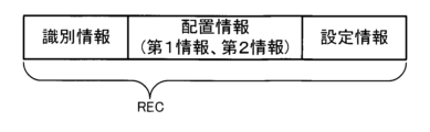
記憶装置240には、設定データベースDBが記憶されている。設定データベースDBは、図2に示すレコードRECの集合体である。つまり、設定データベースDBは、複数のレコードRECにより構成される。図2に示すように、レコードRECには、プロジェクターの機種を一意に示す識別情報及び当該識別情報が示す機種のプロジェクターに関する配置情報に対応付けて設定情報が格納される。
A setting database DB is stored in the
識別情報の具体例としては、プロジェクターの型番を示す文字列、又はプロジェクターの機種名を示す文字列が挙げられる。配置情報は、図2に示すように、第1情報と、第2情報とを含む。第1情報は、当該第1情報を含む配置情報に対応する識別情報の示すプロジェクターと投写面との位置関係を示す。第2情報は、投写面に表示される投写画像の大きさを示す。 A specific example of the identification information is a character string indicating the model number of the projector or a character string indicating the model name of the projector. The arrangement information includes first information and second information, as shown in FIG. The first information indicates the positional relationship between the projector indicated by the identification information corresponding to the arrangement information including the first information and the projection surface. The second information indicates the size of the projection image displayed on the projection plane.
第1情報の具体例としては、プロジェクターと投写面との間の距離を示す情報が挙げられる。なお、プロジェクターと投写面との間の距離を示す情報の他に、プロジェクターの設置場所を示す情報、プロジェクターの設置位置を示す情報、及びプロジェクターの姿勢を示す情報、が第1情報に含まれてもよい。プロジェクターの設置場所を示す情報の一例としては、投写面を含み且つプロジェクターが設置される部屋等の空間においてプロジェクターが天井から吊り下げられているのか、又は机等に置かれているのかを示す情報が挙げられる。プロジェクターの設置位置を示す情報の具体例としては、プロジェクターが設置される空間を区画する各壁からの距離、及び床からの高さを示す情報が挙げられる。プロジェクターの姿勢を示す情報の具体例としては、例えばプロジェクターの重心を通る鉛直軸回りのプロジェクターの回転量、プロジェクターから投写される投写光の光軸回りのプロジェクターの回転量、及び、鉛直軸と直交し且つ光軸とも直交する軸回りのプロジェクターの回転量が挙げられる。 A specific example of the first information is information indicating the distance between the projector and the projection surface. In addition to the information indicating the distance between the projector and the projection surface, the first information includes information indicating the installation location of the projector, information indicating the installation position of the projector, and information indicating the attitude of the projector. good too. An example of information indicating the installation location of the projector is information indicating whether the projector is suspended from the ceiling or placed on a desk in a space such as a room where the projector is installed and which includes the projection surface. is mentioned. A specific example of the information indicating the installation position of the projector is information indicating the distance from each wall that partitions the space in which the projector is installed and the height from the floor. Specific examples of information indicating the attitude of the projector include, for example, the amount of rotation of the projector around the vertical axis passing through the center of gravity of the projector, the amount of rotation of the projector around the optical axis of the projection light projected from the projector, and the amount of rotation of the projector perpendicular to the vertical axis. Moreover, the amount of rotation of the projector around an axis perpendicular to the optical axis can also be mentioned.
第2情報の具体例としては、投写面に表示される投写画像のアスペクト比及び当該投写画像の対角線の長さを示す情報が挙げられる。なお、第2情報には、投写面に表示される投写画像の形状を示す情報が含まれてもよい。投写画像の形状を示す情報の具体例としては、歪みのない矩形、縦台形歪み、横台形歪み、及び縦横合成歪み等、矩形からの乖離の態様及び乖離の程度を示す情報が挙げられる。また、第2情報には、投写面の姿勢を示す情報、又は投写面の種類を示す情報が含まれてもよい。投写面の種類を示す情報の具体例としては、平面、曲面、又は角壁の何れかを示す情報が挙げられる。また、投写面が曲面である場合には、曲率等の投写面のわん曲の程度を示す情報を第2情報に含めてもよい。投写面が角壁である場合には、角壁を構成する各壁面の為す角度を示す情報を第2情報に含めてもよい。 Specific examples of the second information include information indicating the aspect ratio of the projection image displayed on the projection surface and the length of the diagonal line of the projection image. The second information may include information indicating the shape of the projection image displayed on the projection surface. Specific examples of the information indicating the shape of the projected image include information indicating the mode and degree of deviation from the rectangle, such as a rectangle without distortion, vertical trapezoidal distortion, horizontal trapezoidal distortion, vertical and horizontal combined distortion, and the like. The second information may also include information indicating the orientation of the projection surface or information indicating the type of the projection surface. A specific example of the information indicating the type of the projection surface is information indicating any one of a plane, a curved surface, and a corner wall. Further, when the projection surface is a curved surface, information indicating the degree of curvature of the projection surface such as curvature may be included in the second information. When the projection surface is a corner wall, the second information may include information indicating the angle formed by each wall surface forming the corner wall.
設定情報には、当該設定情報の属するレコードRECに含まれる配置情報の第1情報により投写面との位置関係が示されるプロジェクターに、当該配置情報の第2情報の示す大きさの投写画像を投写面に投写させるために用いられる複数の設定値が含まれる。前述したように、設定情報に含まれる設定値の具体例としては、フォーカス値、縦方向及び横方向のレンズシフト量、縦方向及び横方向の台形補正量、及びコーナー補正量が挙げられる。 In the setting information, a projection image having a size indicated by the second information of the layout information is projected onto the projector whose positional relationship with the projection surface is indicated by the first information of the layout information included in the record REC to which the setting information belongs. It contains a number of settings that are used to project onto a surface. As described above, specific examples of setting values included in the setting information include focus values, vertical and horizontal lens shift amounts, vertical and horizontal trapezoidal correction amounts, and corner correction amounts.
本実施形態の設定データベースDBには、識別情報及び配置情報が同じ複数のレコードRECであって、各々異なる設定情報を含む複数のレコードRECが記憶されている場合がある。識別情報及び配置情報が同じであっても、投写光の光量、即ち投写画像の明るさを優先させる場合の設定情報と、投写画像の矩形からの乖離の小ささを優先させる場合の設定情報とは異なり、設定データベースDBには各々の場合に対応するレコードRECが格納され得るからである。このため、識別情報及び配置情報を検索キーとして設定データベースDBを検索した場合、1つのレコードRECがヒットする場合があることは勿論、複数のレコードRECがヒットする場合がある。なお、本実施形態のレコードRECは、識別情報、配置情報、及び設定情報を含むが、これらの他に付加情報を含んでもよい。付加情報の具体例としては、識別情報により機種が示されるプロジェクターが備える投写レンズの型番を示す情報、又は当該プロジェクターの価格を示す情報等が挙げられる。設定データベースDBを構成する複数のレコードRECには、プロジェクター10の識別情報を含むレコードRECが含まれる。
The setting database DB of the present embodiment may store a plurality of records REC having the same identification information and arrangement information and each containing different setting information. Setting information for giving priority to the light amount of projection light, that is, the brightness of the projected image, even if the identification information and arrangement information are the same, and setting information for giving priority to the small deviation from the rectangle of the projected image. This is because the record REC corresponding to each case can be stored in the setting database DB. Therefore, when the setting database DB is searched using the identification information and the arrangement information as search keys, not only one record REC may be hit, but also a plurality of records REC may be hit. Note that the record REC of this embodiment includes identification information, location information, and setting information, but may include additional information in addition to these. Specific examples of the additional information include information indicating the model number of the projection lens included in the projector whose model is indicated by the identification information, information indicating the price of the projector, and the like. A plurality of records REC that configure the setting database DB include a record REC that includes identification information of the
また、記憶装置240の不揮発性メモリーには、処理装置250によって実行されるプログラムP1が予め記憶される。記憶装置240の揮発性メモリーはプログラムP1を実行する際のワークエリアとして処理装置250によって利用される。プログラムP1は、「アプリケーションプログラム」、「アプリケーションソフトウェア」又は「アプリ」とも称され得る。プログラムP1は、例えば、通信装置210を介して不図示のサーバー等から取得され、その後、記憶装置240に記憶される。
A program P1 to be executed by the
処理装置250は、例えばCPU(Central Processing Unit)等のプロセッサー、即ちコンピューターを含んで構成される。処理装置250は、単一のコンピューターで構成されてもよいし、複数のコンピューターで構成されてもよい。処理装置250は、プログラムP1の実行開始を指示する操作がタッチパネル230の入力装置に対して為されたことを契機としてプログラムP1を不揮発性メモリーから揮発性メモリーに読み出し、プログラムP1の実行を開始する。プログラムP1に従って作動中の処理装置250は、図1に示す空間スキャン部251、表示制御部252、操作受付部253、第1取得部254、第2取得部255、及び出力部256として機能する。図1に示す空間スキャン部251、表示制御部252、操作受付部253、第1取得部254、第2取得部255、及び出力部256は、処理装置250をプログラムP1に従って動作させることで実現されるソフトウェアモジュールである。空間スキャン部251、表示制御部252、操作受付部253、第1取得部254、第2取得部255、及び出力部256の各々の機能は次の通りである。
The
空間スキャン部251は、投写面SCを含み且つプロジェクター10が設置される空間を撮像装置220を用いて撮像することにより、当該空間の幅、奥行き及び高さを示す空間情報を、既存のAR(A
ugmented Reality)技術を用いて取得する。この空間情報には、投写面SCを含む空間を撮像装置220により撮像することで得られた画像上の位置と、当該空間における位置とを変換する変換情報が含まれる。空間スキャン部251は、投写面SCを含み且つプロジェクター10が設置される空間内の任意の位置に立って撮像装置220を当該空間の壁に向けた状態で情報処理装置20Aを把持しつつ、当該位置において360°回りながら動画像を撮像することをユーザーに指示するメッセージを表示装置に表示させる。
The
acquired using augmented reality technology. This spatial information includes transformation information for transforming a position on an image obtained by imaging the space including the projection plane SC with the
空間スキャン部251は、ユーザーが撮像装置220により空間を撮像している間、図示せぬ慣性センサーからの出力値を所定時間毎に記憶装置240の揮発性メモリーに追記する。次いで、空間スキャン部251は、撮像装置220により撮像された動画像を構成する複数のフレームの各々について色彩等に基づく自然特徴点を抽出し、各フレームに占める自然特徴点の位置の変化、即ち自然特徴点の動きを特定する。そして、空間スキャン部251は、動画像を構成する複数のフレームに亘る特徴点の動きと、揮発性メモリーに記憶されている一連の出力値の示す撮像装置220の位置及び向きの変化とから、例えばステレオカメラを用いた三次元計測と同様の手法により、空間情報を取得する。
While the user is imaging the space with the
表示制御部252は、プロジェクター10と投写面SCとの位置関係、及びプロジェクター10から投写面SCに投写する投写画像G1の大きさをユーザーに指定させるためのシミュレーション画像をタッチパネル230の表示装置に表示させる。本実施形態におけるシミュレーション画像は、投写面SCを含む空間を撮像装置220により撮像することにより得られた画像に、プロジェクター10を表すアイコンを重畳させた画像である。投写面SCを含む空間の撮像装置220による撮像画像として図3に示す画像G2が得られたとする。図3に示す例では、撮像装置220により撮像される空間を区画する壁のうち奥側の壁に投写画像G1が投写される。つまり、図3に示す例では、撮像装置220により撮像される空間を区画する壁のうちの奥側の壁が投写面SCとなる。撮像装置220による撮像画像として図3に示す画像G2が得られた場合、表示制御部252は、図4に示すように、プロジェクター10を表すアイコンG3を画像G2に重畳させたシミュレーション画像G4をタッチパネル230の表示装置に表示させる。投写面SCを含む空間を撮像装置220により撮像して得られる画像G2は本開示における第2画像の一例である。プロジェクター10を表すアイコンG3は本開示における第3画像の一例である。
The
画像G2は、空間スキャン部251による空間情報の取得過程で撮像した動画像を構成する複数のフレームのうちの何れか一のフレームであってもよいし、当該動画像とは別個に撮像された静止画像であってもよい。前者の態様の場合、投写画像G1の大きさの指定に支障が生じないように、動画像を構成する複数のフレームのうち投写面SCとなる壁が正面に写っているフレームであることが好ましい。後者の態様の場合、空間スキャン部251により取得した空間情報が無効とならないように、動画像の撮像位置と同じ位置から投写面SCを含む空間を撮像することが好ましい。
The image G2 may be any one of a plurality of frames forming a moving image captured in the process of acquiring spatial information by the
操作受付部253は、プロジェクター10と投写面SCとの位置関係、即ち両者の間の距離をシミュレーション画像G4において指定する操作、及び投写画像G1の大きさを指定する操作を受け付ける。より詳細に説明すると、操作受付部253は、これらの操作の実行を促すメッセージをシミュレーション画像G4に重畳させてタッチパネル230の表示装置に表示させる。ユーザーは、シミュレーション画像G4を表示中のタッチパネル230に対してアイコンG3をドラッグアンドドロップする操作を行うことで、プロジェクター10の位置を指定することができる。また、ユーザーは、シミュレーション画像G4を表示中のタッチパネル230に対して投写面SCとする領域をタップする操作を行うことで、投写面SCの位置を指定することができる。例えば、ユーザーは、シミュレーション画像G4のうち奥側の壁に対応する領域をタップすることで、投写面SCの位置を指定する。シミュレーション画像G4上でプロジェクター10の位置及び投写面SCの位置が指定されると、シミュレーション画像G4におけるプロジェクター10と投写面SCとの間の距離、即ち両者の位置関係が定まる。
The
また、投写面SCの位置が指定されると、表示制御部252は、図5に示すように、投写画像G1に対応する矩形の画像G5をシミュレーション画像G4の当該指定された位置に重畳させる。画像G5が重畳されたシミュレーション画像G4は本開示における第4画像の一例である。ユーザーは、画像G5を拡大又は縮小する操作を行うことで、シミュレーション画像G4上での投写画像G1の大きさを指定することができる。画像G5の大きさを指定する操作は本開示における第1操作の一例である。シミュレーション画像G4におけるプロジェクター10と投写面SCとの位置関係を指定する操作は本開示における第2操作の一例である。また、本実施形態では、操作受付部253は、設定情報の出力先のプロジェクター10の機種を示す識別情報を入力する機種指定操作も受け付ける。本実施形態では、ユーザーは、プロジェクター10の識別情報を入力する機種指定操作を実行する。
Further, when the position of the projection plane SC is specified, the
第1取得部254は、投写画像G1の実際の大きさを示すサイズ情報を操作受付部253により受け付けた第1操作に応じて生成する。また、第1取得部254は、プロジェクター10と投写面SCとの実際の位置関係を示す位置関係情報を操作受付部253により受け付けた第2操作に応じて生成する。より詳細に説明すると、第1取得部254は、第1操作により指定された画像G5の大きさを示す情報を、空間情報を用いて変換することでサイズ情報を取得する。同様に、第1取得部254は、第2操作により指定された位置関係を示す情報を、空間情報を用いて変換することで位置関係情報を取得する。また、本実施形態では、第1取得部254は、機種指定操作により入力された識別情報を取得する。
First obtaining
第2取得部255は、第1取得部254にて取得したサイズ情報、位置関係情報、及び識別情報を検索キーとして設定データベースDBを検索することによって、当該検索キーに対応する1又は複数の設定情報を取得する。より詳細に説明すると、第2取得部255は、検索キーに含まれる識別情報と同一の識別情報に対応付けられ、且つ、検索キーに含まれる位置関係情報と同一の第1情報と検索キーに含まれるサイズ情報と同一の第2情報とを含む配置情報に対応付けられる、設定情報を設定データベースDBから取得する。
The
出力部256は、第2取得部255により取得した1又は複数の設定情報のうちの何れか一の設定情報を、通信装置210を介してプロジェクター10へ出力することにより、当該設定情報に含まれる複数の設定値をプロジェクター10に記憶させる。本実施形態では、出力部256は、タッチパネル230に対する操作によりユーザーの指定した設定情報を、通信装置210を介してプロジェクター10へ出力する。なお、識別情報及び配置情報の少なくとも一方と設定情報とが出力されてもよい。
The
また、プログラムP1に従って作動している処理装置250は、本実施形態の特徴を顕著に示す設定方法を実行する。図6は、この設定方法の流れを示すフローチャートである。図6に示すように、この設定方法は、空間スキャン処理SA110、表示制御処理SA120、受付処理SA130、第1取得処理SA140、第2取得処理SA150、第1判定処理SA160、通知処理SA170、第1出力処理SA180、第2出力処理SA190、及び第2判定処理SA200、を含む。
Also, the
空間スキャン処理SA110では、処理装置250は空間スキャン部251として機能する。空間スキャン処理SA110では、処理装置250は、撮像装置220を用いて投写面SCを含む空間を撮像することにより、空間情報を取得する。表示制御処理SA120では、処理装置250は、表示制御部252として機能する。表示制御処理SA120では、処理装置250は、プロジェクター10と投写面SCとの位置関係、及び投写画像G1の大きさをユーザーに指定させるためのシミュレーション画像G4をタッチパネル230の表示装置に表示させる。受付処理SA130では、処理装置250は、操作受付部253として機能する。受付処理SA130では、処理装置250は、第1操作、第2操作、及び機種指定操作、の実行を指示するメッセージを出力し、これらの操作を受け付ける。
The
第1取得処理SA140では、処理装置250は、第1取得部254として機能する。第1取得処理SA140では、処理装置250は、受付処理SA130にて受け付けた第1操作に応じてサイズ情報を取得する。また、第1取得処理SA140では、処理装置250は、受付処理SA130にて受け付けた第2操作に応じて位置関係情報を取得する。また、第1取得処理SA140では、処理装置250は、機種指定操作により受け付けた識別情報を取得する。
In the first acquisition process SA140, the
第2取得処理SA150では、処理装置250は、第2取得部255として機能する。第2取得処理SA150では、処理装置250は、第1取得処理SA140にて取得した配置情報及び識別情報を検索キーとして設定データベースDBを検索することによって、当該検索キーに対応する設定情報を取得する。
In the second acquisition process SA150, the
第1判定処理SA160では、処理装置250は、第2取得処理SA150にて取得された設定情報の個数が0、1、又は2以上の何れであるかを判定する。
In the first determination process SA160, the
第2取得処理SA150にて取得された設定情報の個数が0である場合、処理装置250は、通知処理SA170を実行する。通知処理SA170では、処理装置250は、受付処理SA130にて受け付けた識別情報及び配置情報に対応する設定情報が無いことを示すメッセージをタッチパネル230の表示装置に表示させる。通知処理SA170に後続する第2判定処理SA200では、処理装置250は、識別情報及び配置情報の再入力を指示するための「リトライ」ボタン及び再入力を行わないことを指示するための「終了」ボタンの各仮想操作子をタッチパネル230に表示させ、何れの仮想操作子が押下されたのかを判定する。「リトライ」ボタンを押下する操作が為されたと判定した場合、処理装置250は、受付処理SA130以降の処理を再度実行する。これに対して、「終了」ボタンが押下されたと判定した場合には、処理装置250は、本設定方法を終了する。
When the number of pieces of setting information acquired in the second acquisition process SA150 is 0, the
第2取得処理SA150にて取得された設定情報の個数が1である場合、処理装置250は、第1出力処理SA180を実行する。第1出力処理SA180では、処理装置250は、出力部256として機能する。第1出力処理SA180では、処理装置250は、第2取得処理SA150にて取得された一の設定情報をプロジェクター10へ出力する。なお、投写面SCを含む空間において受付処理SA130にて指定された位置に対応する位置にプロジェクター10が設置済である場合には、第1出力処理SA180にて出力した設定情報に従ってプロジェクター10に投写画像G1を投写させてもよい。ユーザーは、望み通りの投写画像G1が投写面SCに表示されているか否かを実際に確認することができる。第1出力処理SA180の実行を完了すると、処理装置250は、第2判定処理SA200を実行する。望み通りの投写画像G1が投写面SCに表示されている場合、ユーザーは、「終了」ボタンを押下することで、本設定方法を終了させる。望み通りの投写画像G1が投写面SCに表示されていない場合、ユーザーは、「リトライ」ボタンを押下することで、設定情報を再設定することができる。
When the number of pieces of setting information acquired in the second acquisition process SA150 is 1, the
第2取得処理SA150にて取得された設定情報の個数が2以上である場合、処理装置250は、第2出力処理SA190を実行する。第2出力処理SA190では、処理装置250は、出力部256として機能する。第2出力処理SA190では、処理装置250は、第2取得処理SA150にて取得された複数の設定情報のうちの何れか一の設定情報を選択する操作を受け付ける。具体的には、複数の設定情報のうちの何れか一の設定情報をユーザーに選択させ、選択された設定情報がプロジェクター10へ出力される。処理装置250は、複数の設定情報のリストと、ユーザーに一の設定情報の選択を促すメッセージとをタッチパネル230の表示装置に表示させてもよい。なお、投写面SCを含む空間において受付処理SA130にて指定された位置に対応する位置にプロジェクター10が設置済である場合には、第2取得処理SA150にて取得された複数の設定情報の各々を、例えば矩形からの乖離が小さい順に順次プロジェクター10に出力し、望み通りの投写画像G1が投写面SCに投写されるかをユーザーに確認させて一の設定情報をユーザーに選択させてもよい。第2出力処理SA190の実行を完了すると、処理装置250は、第2判定処理SA200を実行する。望み通りの投写画像G1が投写面SCに表示されている場合、ユーザーは、「終了」ボタンを押下することで、本設定方法を終了させる。複数の設定情報の何れによっても望み通りの投写画像G1が投写面SCに表示されなかった場合、ユーザーは、「リトライ」ボタンを押下することで、設定情報を再設定することができる。
When the number of pieces of setting information acquired in the second acquisition process SA150 is two or more, the
以上説明したように本実施形態の情報処理装置20Aによればユーザーは、シミュレーション画像G4におけるアイコンG3の位置を指定する操作、及び画像G5の大きさを指定する操作を行うことによって、当該位置に設置されるプロジェクター10から投写面SCに対して当該大きさの投写画像G1を投写させるための設定情報をプロジェクター10に記憶させることができる。本実施形態の情報処理装置20Aによれば、プロジェクター10の取り扱いに不慣れなユーザーであっても、プロジェクター10の設定を簡便に行うことが可能になる。
As described above, according to the
2.第2実施形態
図7は、本開示の第2実施形態による情報処理装置20B及び情報処理装置20Bを含む通信システムの構成例を示す図である。図7では図1におけるものと同じ構成要素には同じ符号が付されている。図7と図1とを対比すれば明らかなように、情報処理装置20Bの構成は、プログラムP1に代えてプログラムP2が記憶装置240に記憶されている点において情報処理装置20Aの構成と異なる。
2. Second Embodiment FIG. 7 is a diagram illustrating a configuration example of an
図7では、プロジェクター10が点線で描画されている。これは、プロジェクター10が情報処理装置20Bのユーザーの手元には無いことを意味する。プロジェクター10が情報処理装置20Bのユーザーの手元には無いため、本実施形態では、設定データベースDBを検索する際の検索キーとして識別情報が指定されない場合がある。つまり、本実施形態では、設定データベースDBを検索する際の検索キーとして配置情報のみが指定される場合がある。以下、配置情報のみが指定される場合について説明する。
In FIG. 7, the
図7に示すように、情報処理装置20Bを含む通信システムは、発注システム40を含む。発注システム40は、プロジェクター10を購入するための発注の受け付け、及び発注されたプロジェクター10の発送を管理するためのコンピューターシステムである。本実施形態では、情報処理装置20Bは、インターネット等の電気通信回線30を介して発注システム40と通信することができる。本実施形態では、情報処理装置20Bと発注システム40とを連携させることで、発注システム40に対して発注されたプロジェクター10に本開示の設定方法により設定情報を記憶させて、発注を行った発注元へ発送することが可能になる。
As shown in FIG. 7, the communication system including the
情報処理装置20Bの処理装置250は、プログラムP2に従って作動することで、空間スキャン部251、表示制御部252、操作受付部253、第1取得部254、第2取得部255、及び送信部257として機能する。送信部257は、第2取得部255により取得した1又は複数の設定情報のうちの何れか一の設定情報を、通信装置210を介して発注システム40へ送信する。
By operating according to the program P2, the
情報処理装置20Bの処理装置250がプログラムP2に従って実行する設定方法のうち、空間スキャン処理SA110~第1判定処理SA160までの流れは第1実施形態と同じである。但し、受付処理SA130において、機種指定操作、すなわち識別情報の入力が省略される。図8は本実施形態における設定方法の第1判定処理SA160以降の流れを示すフローチャートである。図8と図6とを対比すれば明らかなように、本実施形態における設定方法は、第2取得処理SA150にて取得された設定情報の個数が1又は2以上である場合の処理の流れが、第1実施形態の設定方法と異なる。
Among the setting methods executed by the
第2取得処理SA150にて取得された設定情報の個数が1である場合、処理装置250は、第2取得処理SA150にて取得された設定情報を送信対象の設定情報とし、第3判定処理SB210を実行する。第3判定処理SB210では、処理装置250は、配置情報の再入力を指示するための「リトライ」ボタン及び再入力を行わないことを指示するための「決定」ボタンをタッチパネル230に表示させ、何れのボタンが押下されたのかを判定する。「リトライ」ボタンを押下する操作が為されたと判定した場合、処理装置250は、受付処理SA130以降の処理を再度実行する。これに対して、「決定」ボタンが押下されたと判定した場合には、処理装置250は、接続処理SB220を実行する。
When the number of setting information acquired in the second acquisition process SA150 is 1, the
接続処理SB220では、処理装置250は、通信装置210を用いて発注システム40との間に通信コネクションを確立し、プロジェクター10を発注するための発注画面をタッチパネル230の表示装置に表示させる。接続処理SB220に後続する第4判定処理SB230では、プロジェクター10の発注が為されたか否かを判定する。第4判定処理SB230の判定結果が“Yes”である場合、即ち、プロジェクター10の発注が為されたと検知することを契機として、処理装置250は、送信処理SB240を実行し、その後、本設定方法を終了する。第4判定処理SB230の判定結果が“No”である場合、処理装置250は、送信処理SB240を実行することなく、本設定方法を終了する。送信処理SB240では、処理装置250は、送信対象の設定情報を通信装置210を介して発注システム40へ送信する。
In connection processing SB220,
第2取得処理SA150にて取得された設定情報の個数が2以上である場合、処理装置250は、第2取得処理SA150にて取得された複数の設定情報のうちの何れかをユーザーに選択させる選択処理SB200を実行する。選択処理SB200では、処理装置250は、第2取得処理SA150にて取得された複数の設定情報の各々、及び当該設定情報を含むレコードRECに含まれる識別情報を、例えば矩形からの乖離が小さい順にタッチパネル230の表示装置に順次表示させて、何れか一の設定情報の選択をユーザーに促す。なお、設定データベースDBを構成するレコードRECにプロジェクターの価格を示す付加情報が含まれている場合には、当該付加情報の示す価格の安い順、或いは高い順に識別情報及び設定情報を表示装置に表示させてもよい。そして、処理装置250は、選択処理SB200にて選択された設定情報を送信対象の設定情報とし、第3判定処理SB210以降の処理を実行する。
When the number of pieces of setting information acquired in the second acquisition process SA150 is two or more, the
一方、発注システム40では、プロジェクター10の発注が為されたと検知することを契機として、図9に示す設定処理が実行される。図9に示すように、この設定処理は、受信処理SC110と出力処理SC120とを含む。受信処理SC110では、送信処理SB240により情報処理装置20Bから発注システム40へ送信された設定情報が受信される。出力処理SC120では、受信処理SC110にて受信した設定情報が、発注元へ発送されるプロジェクター10に出力され、プロジェクター10は当該設定情報を記憶する。本実施形態では、図9に示す設定処理により設定情報を設定済のプロジェクター10が、当該プロジェクター10の発注を行った発注元へ発送される。このため、プロジェクター10を受け取ったユーザーは、自身で手作業によりプロジェクター10の設定をしなくてもプロジェクター10を使用できるので簡便である。
On the other hand, the
以上説明したように本実施形態の情報処理装置20Bによっても、ユーザーは、シミュレーション画像G4におけるアイコンG3の位置を指定する操作、及び画像G5の大きさを指定する操作を行うことによって、当該位置に設置されるプロジェクター10から投写面SCに対して当該大きさの投写画像G1を投写させるための設定情報をプロジェクター10に記憶させることができる。本実施形態の情報処理装置20Bよっても、プロジェクター10の取り扱いに不慣れなユーザーであっても、プロジェクター10の設定を簡便に行うことが可能になる。なお、本実施形態における発注システム40は、プロジェクター10を購入するための発注を受け付けるコンピューターシステムであったが、プロジェクター10のレンタルに関する発注を受け付けるコンピューターシステムであってもよい。
As described above, also with the
3.変形
上記各実施形態は、以下のように変形され得る。
(1)第2実施形態では、発注システム40ではプロジェクター10の発注が為されたと検知することを契機として、図9に示す設定処理が実行され、受信処理SC110にて受信した設定情報を設定済のプロジェクター10が発注元へ発送された。しかし、受信処理SC110に後続して出力処理SC120が即座に実行される必要はない。例えば、受信処理SC110に後続して、設定情報を記憶させていない状態のプロジェクター10の発注元への発送が実行され、当該プロジェクター10が電気通信回線30を介して発注システム40へアクセスしたことを契機として出力処理SC120が実行されてもよい。本態様によっても、第2実施形態と同じ効果が奏される。
3. Modifications Each of the above embodiments can be modified as follows.
(1) In the second embodiment, when the
(2)図9に示す受信処理SC110の実行後、出力処理SC120の実行前に、発注元へ発送されるプロジェクター10に接続されるメモリスティック等の記憶装置に受信処理SC110にて受信した設定情報を書き込む処理が実行されてもよい。プロジェクター10に接続される記憶装置は第2記憶装置とも称される。本態様における出力処理SC120は、第2記憶装置がプロジェクター10に接続されたこと契機として当該第2記憶装置からプロジェクター10へ設定情報を出力する処理である。本態様における出力処理SC120は発注システム40側で実行されてもよく、また、発注元で実行されてもよい。本態様における出力処理SC120が発注システム40側で実行される場合、発注元に対して、設定情報を設定済のプロジェクター10が発送される。本態様における出力処理SC120が発注元で実行される場合、受信処理SC110にて受信した設定情報が書き込まれた第2記憶装置と、設定情報を未設定のプロジェクター10とが発注元へ発送される。また、出力処理SC120を発注システム40側で実行する態様の場合、プロジェクター10の発注元に第2記憶装置を指定させ、当該第2記憶装置に対する設定情報の書き込みが電気通信回線30を介して行われてもよい。プロジェクター10の発注元により指定された第2記憶装置に設定情報を書き込む態様においては、第2記憶装置の発送は不要である。
(2) After execution of the reception processing SC110 shown in FIG. 9 and before execution of the output processing SC120, the setting information received by the reception processing SC110 in a storage device such as a memory stick connected to the
(3)第1実施形態における空間スキャン部251、表示制御部252、操作受付部253、第1取得部254、第2取得部255、及び出力部256は、ソフトウェアモジュールであったが、ASIC(Application Specific Integrated Circuit)等のハードウェアモジュールであってもよい。第2実施形態における空間スキャン部251、表示制御部252、操作受付部253、第1取得部254、第2取得部255、及び送信部257も、ASIC等のハードウェアモジュールであってもよい。また、第1実施形態では、情報処理装置20Aの記憶装置240に設定データベースDBが記憶されていた。しかし、情報処理装置20Aの処理装置250が通信装置210を介してアクセス可能な記憶装置に設定データベースDBが記憶されていてもよい。第2実施形態における設定データベースDBも同様である。
(3) The
(4)第1実施形態及び第2実施形態では、処理装置250は、投写画像G1に対応する画像G5の大きさを指定する第1操作、及びプロジェクター10に対応するアイコンG3の位置を指定する操作に応じて配置情報を取得した。しかし、プロジェクター10と投写面SCとの位置関係を示す第1情報及び投写画像G1の大きさを示す第2情報を数値でユーザーに入力させ、処理装置250はユーザーにより入力された数値に応じて配置情報を取得してもよい。第1情報及び第2情報を数値でユーザーにさせる態様の場合、空間スキャン部251及び表示制御部252は不要である。同様に、空間スキャン処理SA110及び表示制御処理SA120も不要である。
(4) In the first and second embodiments, the
(5)第1実施形態における情報処理装置20A及び第2実施形態における情報処理装置20Bはスマートフォンであった。しかし、情報処理装置20A及び情報処理装置20Bは、タブレット端末、又はパーソナルコンピューターであってもよい。また、上記第1実施形態では、プログラムP1が情報処理装置20Aの記憶装置240に予め記憶されていた。しかし、プログラムP1が単体で製造又は配布されてもよい。プログラムP1の具体的な配布態様としては、フラッシュROM(Read Only Memory)等のコンピューター読取可能な記録媒体にプログラムP1を書き込んで配布する態様、又はインターネット等の電気通信回線経由のダウンロードにより配布する態様が挙げられる。これらの態様により配布されるプログラムP1に従って一般的なスマートフォンのコンピューターを作動させることで、当該スマートフォンを本開示の情報処理装置として機能させることが可能になる。同様に、第2実施形態におけるプログラムP2も、単体で製造又は配布されてもよい。
(5) The
4.実施形態及び各変形例の少なくとも1つから把握される態様
本開示は、上述した実施形態及び変形例に限られるものではなく、その趣旨を逸脱しない範囲において種々の態様で実現することができる。例えば、本開示は、以下の態様によっても実現可能である。以下に記載した各態様中の技術的特徴に対応する上記実施形態中の技術的特徴は、本開示の課題の一部又は全部を解決するために、或いは本開示の効果の一部又は全部を達成するために、適宜、差し替えや、組み合わせを行うことが可能である。また、その技術的特徴が本明細書中に必須なものとして説明されていなければ、適宜、削除することが可能である。
4. Aspects Grasp from At Least One of Embodiments and Modifications The present disclosure is not limited to the above-described embodiments and modifications, and can be implemented in various manners without departing from the gist thereof. For example, the present disclosure can also be implemented by the following aspects. The technical features in the above embodiments corresponding to the technical features in each aspect described below are used to solve some or all of the problems of the present disclosure, or to achieve some or all of the effects of the present disclosure. To achieve this, it is possible to make suitable substitutions and combinations. Also, if the technical features are not described as essential in this specification, they can be deleted as appropriate.
本開示の設定方法の一態様は、以下の第1取得処理SA140と、第2取得処理SA150と、以下の出力処理と、を含んでいればよい。第1取得処理SA140では、プロジェクター10と投写面SCとの位置関係を示す第1情報とプロジェクター10から投写面SCに投写される投写画像G1の大きさを示す第2情報とを含む配置情報が取得される。第2取得処理SA150では、第1取得処理SA140にて取得された配置情報に基づいて、1又は複数の設定情報が取得される。1又は複数の設定情報の各々は、投写面SCに対してプロジェクター10が投写画像G1を投写するために用いられる複数の設定値を含む。出力処理は、第1出力処理SA180及び第2出力処理SA190、又は送信処理SB240にて送信された設定情報をプロジェクター10へ出力する処理の何れかである。出力処理では、第2取得処理SA150にて取得された1又は複数の設定情報のうちの何れか一の設定情報がプロジェクター10へ出力される。本態様の設定方法によれば、投写面SCに対して第1情報の示す位置関係にあるプロジェクター10から、第2情報の示す大きさの投写画像G1を投写面SCに投写するための設定情報をプロジェクター10に簡便に設定することが可能になる。
One aspect of the setting method of the present disclosure may include the following first acquisition processing SA140, second acquisition processing SA150, and the following output processing. In the first acquisition process SA140, arrangement information including first information indicating the positional relationship between the
より好ましい態様の設定方法は、以下の撮像処理、表示制御処理SA120、及び受付処理SA130を含んでも良い。撮像処理では、投写面SCを含む空間の撮像装置220による撮像画像が取得される。表示制御処理SA120では、投写画像G1に対応する画像G5及びプロジェクター10を表すアイコンG3を当該撮像画像に重畳させたシミュレーション画像G4がタッチパネル230の表示装置に表示される。受付処理SA130では、画像G5の大きさを指定する第1操作、及びアイコンG3の位置を指定する第2操作が受け付けられる。そして、第1取得処理SA140では、受付処理SA130にて受け付けた第1操作及び第2操作に応じて配置情報が取得される。本態様によれば、シミュレーション画像G4に対して第1操作及び第2操作を行うという簡単な手順により、配置情報を取得することが可能になる。
A setting method of a more preferable aspect may include the following imaging processing, display control processing SA120, and reception processing SA130. In the imaging process, an image captured by the
より好ましい態様の設定方法は、1又は複数の設定情報が複数の設定情報ある場合、受付処理SA130では、複数の設定情報のうちからプロジェクター10へ出力する一の設定情報を選択する操作が受け付けられてもよい。本態様によれば、複数の設定情報のうちプロジェクター10へ出力する一の設定情報をユーザーに選択させることが可能になる。
In a more preferable setting method, when one or more pieces of setting information include a plurality of pieces of setting information, an operation of selecting one piece of setting information to be output to the
より好ましい態様の設定方法は、一の設定情報を、プロジェクター10に関する発注を受け付ける発注システム40へ送信する送信処理SB240を更に含んでもよい。本態様によれば、発注システム40に対して発注されるプロジェクター10に、当該プロジェクター10と投写面SCとの位置関係及び投写画像G1の大きさに応じた設定情報を発注システム40側で設定することが可能になる。ユーザーは、自身で手作業によりプロジェクター10の設定をしなくてもプロジェクター10を使用できるので簡便である。
A more preferable setting method may further include a transmission process SB240 of transmitting one piece of setting information to the
更に好ましい態様の設定方法では、送信処理SB240は、発注システム40に対してプロジェクター10の発注が為されたと検知することを契機として実行されてもよい。本態様における出力処理では、発注システム40が、受信した一の設定情報を、発注元へ発送されるプロジェクター10に出力する。本態様によれば、発注システム40に対して発注されたプロジェクター10に当該プロジェクター10と投写面SCとの位置関係及び投写画像G1の大きさに応じた設定情報を設定し、当該設定情報を設定済のプロジェクター10を発注元へ発送することが可能になる。本態様によっても、ユーザーは、自身で手作業によりプロジェクター10の設定をしなくてもプロジェクター10を使用できるので簡便である。
In a further preferred setting method, the transmission process SB240 may be triggered by detecting that an order for the
更に好ましい態様の設定方法では、出力処理は、発注元へ発送されたプロジェクター10が発注システム40へアクセスしたことを契機として実行されてもよい、この態様における出力処理では、発注システム40が、受信した一の設定情報を、発注元へ発送されたプロジェクター10に出力する。本態様によれば、発注元にて受領されたプロジェクター10に、当該プロジェクター10と投写面SCとの位置関係及び投写画像G1の大きさに応じた設定情報を設定することが可能になる。本態様によっても、ユーザーは、自身で手作業によりプロジェクター10の設定をしなくてもプロジェクター10を使用できるので簡便である。
In a further preferred setting method, the output process may be executed when the
より好ましい態様の設定方法における出力処理は、受信した設定情報を、発注元へ発送されるプロジェクター10に接続される記憶装置へ発注システム40が出力する処理と、発注元へ発送されたプロジェクター10に記憶装置が接続されたことを契機として当該記憶装置から設定情報をプロジェクター10へ出力する処理とを含んでもよい。本態様によれば、発注システム40に対して発注されたプロジェクター10に、当該プロジェクター10と投写面SCとの位置関係及び投写画像G1の大きさに応じた設定情報を設定することが可能になる。本態様によっても、ユーザーは、自身で手作業によりプロジェクター10の設定をしなくてもプロジェクター10を使用できるので簡便である。
The output processing in the setting method of the more preferred embodiment includes processing for the
本開示のプログラムの一態様は、コンピューターに、前述の第1取得処理SA140と第2取得処理SA150とを実行させる。本態様のプログラムによっても、プロジェクター10と投写面SCとの位置関係及び投写画像G1の大きさを指定することで、プロジェクター10と投写面SCとの位置関係及び投写画像G1の大きさに応じた設定情報をプロジェクター10に簡便に設定することが可能になる。
One aspect of the program of the present disclosure causes the computer to execute the above-described first acquisition process SA140 and second acquisition process SA150. By specifying the positional relationship between the
10…プロジェクター、20A、20B…情報処理装置、30…電気通信回線、40…発注システム、210…通信装置、220…撮像装置、230…タッチパネル、240…記憶装置、250…処理装置、251…空間スキャン部、252…表示制御部、253…操作受付部、254…第1取得部、255…第2取得部、256…出力部、257…送信部、P1,P2…プログラム、DB…設定データベース。
DESCRIPTION OF
Claims (8)
前記配置情報に基づいて、1又は複数の設定情報を取得すること、及び、
前記1又は複数の設定情報のうちの何れか一の設定情報を前記プロジェクターへ出力すること、を含み、
前記1又は複数の設定情報の各々は、前記投写面に対して前記プロジェクターが前記第1画像を投写するために用いられる複数の設定値を含む、
設定方法。 Acquiring arrangement information including first information indicating a positional relationship between a projector and a projection surface and second information indicating a size of a first image projected from the projector onto the projection surface;
obtaining one or more setting information based on the configuration information; and
outputting any one of the one or more setting information to the projector;
each of the one or more setting information includes a plurality of setting values used by the projector to project the first image onto the projection surface;
Setting method.
前記第1画像に対応する画像及び前記プロジェクターを表す第3画像を前記第2画像に重畳させた第4画像を表示装置に表示させること、及び、
前記第4画像における前記第1画像の大きさを指定する第1操作、及び前記第4画像における前記第3画像の位置を指定する第2操作、を受け付けること、を更に含み、
受け付けた前記第1操作及び前記第2操作に応じて前記配置情報を取得する、請求項1に記載の設定方法。 Acquiring a second image obtained by capturing an image of a space including the projection plane using an imaging device;
causing a display device to display a fourth image in which an image corresponding to the first image and a third image representing the projector are superimposed on the second image;
further comprising accepting a first operation of specifying the size of the first image in the fourth image and a second operation of specifying the position of the third image in the fourth image;
2. The setting method according to claim 1, wherein said arrangement information is acquired according to said first operation and said second operation that have been received.
前記出力することは、前記発注システムが、前記一の設定情報を、前記プロジェクターに出力する、
請求項4に記載の設定方法。 Sending to the ordering system includes sending the one setting information to the ordering system upon detecting that the ordering system has placed an order for the projector;
In the outputting, the ordering system outputs the one setting information to the projector;
The setting method according to claim 4.
前記発注システムが、前記一の設定情報を、前記プロジェクタ―に接続される記憶装置へ出力すること、を更に含み、
前記出力することは、前記プロジェクターに前記記憶装置が接続されたことを契機として、前記一の設定情報が、前記記憶装置から、前記プロジェクターへ出力される、
請求項4に記載の設定方法。 The transmission to the ordering system means that the ordering system transmits the one setting information to the ordering system upon detecting that the ordering system has placed an order for the projector. including
further comprising the ordering system outputting the one setting information to a storage device connected to the projector;
In the step of outputting, when the storage device is connected to the projector, the one setting information is output from the storage device to the projector.
The setting method according to claim 4.
プロジェクターと投写面との位置関係を示す第1情報と前記プロジェクターから前記投写面に投写される第1画像の大きさを示す第2情報とを含む配置情報、を取得すること、及び、
前記配置情報に基づいて、1又は複数の設定情報を取得すること、を実行させ、
前記1又は複数の設定情報の各々は、前記投写面に対して前記プロジェクターが前記第1画像を投写するために用いられる複数の設定値を含む、
プログラム。 to the computer,
Acquiring arrangement information including first information indicating a positional relationship between a projector and a projection surface and second information indicating a size of a first image projected from the projector onto the projection surface;
Acquiring one or more setting information based on the arrangement information;
each of the one or more setting information includes a plurality of setting values used by the projector to project the first image onto the projection surface;
program.
Priority Applications (3)
| Application Number | Priority Date | Filing Date | Title |
|---|---|---|---|
| JP2021016090A JP7243748B2 (en) | 2021-02-03 | 2021-02-03 | Setting method and program |
| CN202210106670.6A CN114866749B (en) | 2021-02-03 | 2022-01-28 | Setting method and recording medium |
| US17/591,014 US11889237B2 (en) | 2021-02-03 | 2022-02-02 | Setting method and a non-transitory computer-readable storage medium storing a program |
Applications Claiming Priority (1)
| Application Number | Priority Date | Filing Date | Title |
|---|---|---|---|
| JP2021016090A JP7243748B2 (en) | 2021-02-03 | 2021-02-03 | Setting method and program |
Publications (2)
| Publication Number | Publication Date |
|---|---|
| JP2022119093A JP2022119093A (en) | 2022-08-16 |
| JP7243748B2 true JP7243748B2 (en) | 2023-03-22 |
Family
ID=82611944
Family Applications (1)
| Application Number | Title | Priority Date | Filing Date |
|---|---|---|---|
| JP2021016090A Active JP7243748B2 (en) | 2021-02-03 | 2021-02-03 | Setting method and program |
Country Status (3)
| Country | Link |
|---|---|
| US (1) | US11889237B2 (en) |
| JP (1) | JP7243748B2 (en) |
| CN (1) | CN114866749B (en) |
Citations (2)
| Publication number | Priority date | Publication date | Assignee | Title |
|---|---|---|---|---|
| JP2017116689A (en) | 2015-12-24 | 2017-06-29 | セイコーエプソン株式会社 | Image projection system, control method for the same, terminal device, and program |
| JP2020134895A (en) | 2019-02-26 | 2020-08-31 | セイコーエプソン株式会社 | Method for display and display system |
Family Cites Families (13)
| Publication number | Priority date | Publication date | Assignee | Title |
|---|---|---|---|---|
| JP2001229306A (en) | 2000-02-15 | 2001-08-24 | Tis Inc | Electronic commercial transaction system including simulation means |
| US20030236707A1 (en) | 2002-06-19 | 2003-12-25 | Cheney Douglas A. | Configuring a product with user settings during a network purchase |
| EP1385335B1 (en) * | 2002-07-23 | 2009-04-22 | NEC Display Solutions, Ltd. | Image projector with image-feedback control |
| JP2005313291A (en) | 2004-04-30 | 2005-11-10 | Mitsubishi Heavy Ind Ltd | Image display method linked with robot action, and device thereof |
| JP2014056044A (en) | 2012-09-11 | 2014-03-27 | Ricoh Co Ltd | Image projection system, operation method of image projection system, image projection device, and remote control device of image projection system |
| WO2015098189A1 (en) * | 2013-12-27 | 2015-07-02 | ソニー株式会社 | Display control device, display control method, and program |
| JP6344002B2 (en) * | 2014-01-21 | 2018-06-20 | セイコーエプソン株式会社 | Position detection apparatus and adjustment method |
| JP2017059931A (en) | 2015-09-15 | 2017-03-23 | 株式会社リコー | Image projection system, information processing unit and program |
| JPWO2017179272A1 (en) | 2016-04-15 | 2019-02-21 | ソニー株式会社 | Information processing apparatus, information processing method, and program |
| WO2019017023A1 (en) | 2017-07-19 | 2019-01-24 | ソニー株式会社 | Information processing device, information processing method, and program |
| JP2019040003A (en) * | 2017-08-24 | 2019-03-14 | セイコーエプソン株式会社 | Projector and method for controlling projector |
| JP2019045549A (en) * | 2017-08-30 | 2019-03-22 | セイコーエプソン株式会社 | Image projection system, terminal device, and control method for image projection system |
| CN109587458B (en) * | 2017-09-29 | 2021-10-15 | 中强光电股份有限公司 | Projection system and automatic setting method thereof |
-
2021
- 2021-02-03 JP JP2021016090A patent/JP7243748B2/en active Active
-
2022
- 2022-01-28 CN CN202210106670.6A patent/CN114866749B/en active Active
- 2022-02-02 US US17/591,014 patent/US11889237B2/en active Active
Patent Citations (2)
| Publication number | Priority date | Publication date | Assignee | Title |
|---|---|---|---|---|
| JP2017116689A (en) | 2015-12-24 | 2017-06-29 | セイコーエプソン株式会社 | Image projection system, control method for the same, terminal device, and program |
| JP2020134895A (en) | 2019-02-26 | 2020-08-31 | セイコーエプソン株式会社 | Method for display and display system |
Also Published As
| Publication number | Publication date |
|---|---|
| CN114866749A (en) | 2022-08-05 |
| US20220247985A1 (en) | 2022-08-04 |
| US11889237B2 (en) | 2024-01-30 |
| JP2022119093A (en) | 2022-08-16 |
| CN114866749B (en) | 2023-05-26 |
Similar Documents
| Publication | Publication Date | Title |
|---|---|---|
| US8094242B2 (en) | Object management apparatus, mobile terminal, and object management method | |
| CN105320695A (en) | Picture processing method and device | |
| JP2017135659A (en) | Image management system, image management method, image communication system and program | |
| JP2005065118A (en) | Mobile terminal with remote control function and remote control server | |
| JP7367812B2 (en) | Information processing system, information processing method and program | |
| US11062422B2 (en) | Image processing apparatus, image communication system, image processing method, and recording medium | |
| US11811976B2 (en) | Information processing system to obtain and manage images of a property | |
| US11048345B2 (en) | Image processing device and image processing method | |
| JP5614116B2 (en) | Communication terminal | |
| JP7243748B2 (en) | Setting method and program | |
| CN114979616B (en) | Display method, information processing apparatus, and recording medium | |
| JP6617547B2 (en) | Image management system, image management method, and program | |
| JP5216703B2 (en) | Video display system and video display method | |
| JP7130215B1 (en) | Planned building confirmation system | |
| JP7012485B2 (en) | Image information processing device and image information processing method | |
| JP6986214B2 (en) | Display system and display device | |
| JP6620979B2 (en) | Portable terminal, projection system, control method and program for projection system | |
| JP7398184B1 (en) | Video provision system, video provision method, and video provision program | |
| JP4507665B2 (en) | How to register phone location information | |
| EP3863274A1 (en) | Information processing method, carrier means, and information processing apparatus | |
| JP2017122975A (en) | Information processing apparatus, information processing method, and program | |
| JP2017182548A (en) | Image management system, image management method, image communication system, and program | |
| KR20230031897A (en) | Shooting support device, method and program | |
| JP2014032589A (en) | Electronic device |
Legal Events
| Date | Code | Title | Description |
|---|---|---|---|
| A521 | Request for written amendment filed |
Free format text: JAPANESE INTERMEDIATE CODE: A523 Effective date: 20220128 |
|
| A621 | Written request for application examination |
Free format text: JAPANESE INTERMEDIATE CODE: A621 Effective date: 20220128 |
|
| TRDD | Decision of grant or rejection written | ||
| A01 | Written decision to grant a patent or to grant a registration (utility model) |
Free format text: JAPANESE INTERMEDIATE CODE: A01 Effective date: 20230207 |
|
| A61 | First payment of annual fees (during grant procedure) |
Free format text: JAPANESE INTERMEDIATE CODE: A61 Effective date: 20230220 |
|
| R150 | Certificate of patent or registration of utility model |
Ref document number: 7243748 Country of ref document: JP Free format text: JAPANESE INTERMEDIATE CODE: R150 |