JP7240241B2 - Imaging device and its control method, attitude angle calculation device, program, storage medium - Google Patents
Imaging device and its control method, attitude angle calculation device, program, storage medium Download PDFInfo
- Publication number
- JP7240241B2 JP7240241B2 JP2019083211A JP2019083211A JP7240241B2 JP 7240241 B2 JP7240241 B2 JP 7240241B2 JP 2019083211 A JP2019083211 A JP 2019083211A JP 2019083211 A JP2019083211 A JP 2019083211A JP 7240241 B2 JP7240241 B2 JP 7240241B2
- Authority
- JP
- Japan
- Prior art keywords
- imaging device
- motion vector
- angular velocity
- detection
- value
- Prior art date
- Legal status (The legal status is an assumption and is not a legal conclusion. Google has not performed a legal analysis and makes no representation as to the accuracy of the status listed.)
- Active
Links
Images


Classifications
-
- G—PHYSICS
- G06—COMPUTING; CALCULATING OR COUNTING
- G06T—IMAGE DATA PROCESSING OR GENERATION, IN GENERAL
- G06T7/00—Image analysis
- G06T7/20—Analysis of motion
- G06T7/223—Analysis of motion using block-matching
-
- G—PHYSICS
- G06—COMPUTING; CALCULATING OR COUNTING
- G06T—IMAGE DATA PROCESSING OR GENERATION, IN GENERAL
- G06T7/00—Image analysis
- G06T7/70—Determining position or orientation of objects or cameras
-
- G—PHYSICS
- G01—MEASURING; TESTING
- G01C—MEASURING DISTANCES, LEVELS OR BEARINGS; SURVEYING; NAVIGATION; GYROSCOPIC INSTRUMENTS; PHOTOGRAMMETRY OR VIDEOGRAMMETRY
- G01C1/00—Measuring angles
-
- G—PHYSICS
- G01—MEASURING; TESTING
- G01C—MEASURING DISTANCES, LEVELS OR BEARINGS; SURVEYING; NAVIGATION; GYROSCOPIC INSTRUMENTS; PHOTOGRAMMETRY OR VIDEOGRAMMETRY
- G01C21/00—Navigation; Navigational instruments not provided for in groups G01C1/00 - G01C19/00
- G01C21/04—Navigation; Navigational instruments not provided for in groups G01C1/00 - G01C19/00 by terrestrial means
- G01C21/08—Navigation; Navigational instruments not provided for in groups G01C1/00 - G01C19/00 by terrestrial means involving use of the magnetic field of the earth
-
- G—PHYSICS
- G01—MEASURING; TESTING
- G01P—MEASURING LINEAR OR ANGULAR SPEED, ACCELERATION, DECELERATION, OR SHOCK; INDICATING PRESENCE, ABSENCE, OR DIRECTION, OF MOVEMENT
- G01P13/00—Indicating or recording presence, absence, or direction, of movement
-
- G—PHYSICS
- G01—MEASURING; TESTING
- G01P—MEASURING LINEAR OR ANGULAR SPEED, ACCELERATION, DECELERATION, OR SHOCK; INDICATING PRESENCE, ABSENCE, OR DIRECTION, OF MOVEMENT
- G01P15/00—Measuring acceleration; Measuring deceleration; Measuring shock, i.e. sudden change of acceleration
- G01P15/02—Measuring acceleration; Measuring deceleration; Measuring shock, i.e. sudden change of acceleration by making use of inertia forces using solid seismic masses
- G01P15/08—Measuring acceleration; Measuring deceleration; Measuring shock, i.e. sudden change of acceleration by making use of inertia forces using solid seismic masses with conversion into electric or magnetic values
-
- G—PHYSICS
- G01—MEASURING; TESTING
- G01P—MEASURING LINEAR OR ANGULAR SPEED, ACCELERATION, DECELERATION, OR SHOCK; INDICATING PRESENCE, ABSENCE, OR DIRECTION, OF MOVEMENT
- G01P3/00—Measuring linear or angular speed; Measuring differences of linear or angular speeds
-
- G—PHYSICS
- G06—COMPUTING; CALCULATING OR COUNTING
- G06T—IMAGE DATA PROCESSING OR GENERATION, IN GENERAL
- G06T7/00—Image analysis
- G06T7/70—Determining position or orientation of objects or cameras
- G06T7/73—Determining position or orientation of objects or cameras using feature-based methods
-
- G—PHYSICS
- G06—COMPUTING; CALCULATING OR COUNTING
- G06T—IMAGE DATA PROCESSING OR GENERATION, IN GENERAL
- G06T2207/00—Indexing scheme for image analysis or image enhancement
- G06T2207/10—Image acquisition modality
- G06T2207/10016—Video; Image sequence
-
- G—PHYSICS
- G06—COMPUTING; CALCULATING OR COUNTING
- G06T—IMAGE DATA PROCESSING OR GENERATION, IN GENERAL
- G06T2207/00—Indexing scheme for image analysis or image enhancement
- G06T2207/20—Special algorithmic details
- G06T2207/20021—Dividing image into blocks, subimages or windows
-
- G—PHYSICS
- G06—COMPUTING; CALCULATING OR COUNTING
- G06T—IMAGE DATA PROCESSING OR GENERATION, IN GENERAL
- G06T2207/00—Indexing scheme for image analysis or image enhancement
- G06T2207/30—Subject of image; Context of image processing
- G06T2207/30244—Camera pose
Landscapes
- Engineering & Computer Science (AREA)
- General Physics & Mathematics (AREA)
- Physics & Mathematics (AREA)
- Remote Sensing (AREA)
- Radar, Positioning & Navigation (AREA)
- Computer Vision & Pattern Recognition (AREA)
- Theoretical Computer Science (AREA)
- Multimedia (AREA)
- Geology (AREA)
- Automation & Control Theory (AREA)
- General Life Sciences & Earth Sciences (AREA)
- Environmental & Geological Engineering (AREA)
- Life Sciences & Earth Sciences (AREA)
- Studio Devices (AREA)
- Gyroscopes (AREA)
- Accessories Of Cameras (AREA)
- Adjustment Of Camera Lenses (AREA)
Description
本発明は、姿勢情報を要する撮像装置において、複数のセンサを用いて撮像装置の姿勢を推定する技術に関するものである。 The present invention relates to a technique for estimating the posture of an imaging device that requires posture information using a plurality of sensors.
従来より、角速度センサ、加速度センサ、地磁気センサが搭載されたセンサデバイスを用いて、運動中の物体の姿勢を推定する方法が知られている。角速度センサの検出結果から、相対的な姿勢変化が算出できる。したがって、この姿勢変化を積算することにより、姿勢を推定できる。 2. Description of the Related Art Conventionally, there has been known a method of estimating the posture of a moving object using a sensor device equipped with an angular velocity sensor, an acceleration sensor, and a geomagnetic sensor. A relative attitude change can be calculated from the detection result of the angular velocity sensor. Therefore, the posture can be estimated by accumulating the posture changes.
一方で、角速度センサの出力値には、誤差が含まれているため、角速度センサの出力値を積算し続けると、算出される姿勢は徐々に真値から外れていく。このため、角速度センサの出力値を地磁気センサの出力を用いて補正する方法が提案されている。 On the other hand, since the output value of the angular velocity sensor contains an error, if the output value of the angular velocity sensor continues to be integrated, the calculated attitude gradually deviates from the true value. Therefore, a method of correcting the output value of the angular velocity sensor using the output of the geomagnetic sensor has been proposed.
例えば、特許文献1には、角速度センサ、加速度センサ、地磁気センサが搭載されたセンサデバイスの出力値に基づき、カルマンフィルタを用いて、現在の姿勢を表すクォータニオンを推定し出力する小型姿勢センサが開示されている。 For example, Patent Document 1 discloses a compact attitude sensor that estimates and outputs a quaternion representing the current attitude using a Kalman filter based on the output values of a sensor device equipped with an angular velocity sensor, an acceleration sensor, and a geomagnetic sensor. ing.
しかしながら、特許文献1に開示されている技術では以下のような問題がある。特許文献1では、移動物体の独立な3軸上の角速度を計測する角速度センサ、加速度センサ、地磁気センサの出力値に基づいてクォータニオンの推定値を算出する必要がある。しかし、金属製の物体を近づける、地磁気が得られない場所へ移動する、地磁気センサがキャリブレーションされていないなど、地磁気センサの出力値を正確に得られない状況では、クォータニオンを推定できない。そのため、特許文献1に開示されている技術では、精度良く姿勢を推定できない場合がある。 However, the technique disclosed in Patent Document 1 has the following problems. In Patent Document 1, it is necessary to calculate an estimated value of a quaternion based on the output values of an angular velocity sensor, an acceleration sensor, and a geomagnetic sensor that measure angular velocities of a moving object on three independent axes. However, the quaternion cannot be estimated in situations where the output value of the geomagnetic sensor cannot be obtained accurately, such as when a metal object is approached, when the geomagnetism sensor is not calibrated, or when the geomagnetism sensor is not calibrated. Therefore, the technique disclosed in Patent Literature 1 may not be able to accurately estimate the posture.
本発明は上述した課題に鑑みてなされたものであり、その目的は、角速度センサ及び加速度センサの出力値から姿勢を推定する場合に、地磁気センサの出力値が得られない状況でも、高精度に姿勢を推定することができる撮像装置を提供することである。 The present invention has been made in view of the above-mentioned problems, and its object is to accurately estimate the posture from the output values of the angular velocity sensor and the acceleration sensor even in situations where the output value of the geomagnetic sensor cannot be obtained. An object of the present invention is to provide an imaging device capable of estimating a posture.
本発明に係わる撮像装置は、撮像装置であって、前記撮像装置の動きの角速度を検出する角速度検出手段と、前記撮像装置の動きの加速度を検出する加速度検出手段と、前記撮像装置で撮像された画像に基づいて動きベクトルを検出する動きベクトル検出手段と、前記角速度検出手段の検出値と、前記加速度検出手段の検出値と、前記動きベクトル検出手段の検出値とに基づいて前記撮像装置の姿勢角を算出する算出手段と、を備え、前記算出手段は、前記動きベクトル検出手段により得られた検出値を用いて前記角速度検出手段の出力を補正し、補正した値に基づいて前記撮像装置の姿勢角を算出することを特徴とする。 An image pickup apparatus according to the present invention is an image pickup apparatus comprising: angular velocity detection means for detecting an angular velocity of movement of the image pickup apparatus; acceleration detection means for detecting acceleration of movement of the image pickup apparatus; motion vector detection means for detecting a motion vector based on the captured image; detection values of the angular velocity detection means; detection values of the acceleration detection means; and detection values of the motion vector detection means. calculating means for calculating an attitude angle, wherein the calculating means corrects the output of the angular velocity detecting means using the detection value obtained by the motion vector detecting means, and the imaging apparatus based on the corrected value. It is characterized by calculating the attitude angle of
本発明に係わる姿勢角算出装置は、撮像装置の動きの角速度情報を取得する角速度取得手段と、前記撮像装置の動きの加速度情報を取得する加速度取得手段と、前記撮像装置で撮像された画像に基づく動きベクトル情報を取得する動きベクトル取得手段と、前記角速度取得手段により取得した角速度情報と、前記加速度取得手段により取得した加速度情報と、前記動きベクトル取得手段により取得した動きベクトル情報とに基づいて前記撮像装置の姿勢角を算出する算出手段と、を備え、前記算出手段は、前記動きベクトル検出手段により取得した動きベクトル情報を用いて前記角速度取得手段により取得した角速度情報を補正し、補正した情報に基づいて前記撮像装置の姿勢角を算出することを特徴とする。 A posture angle calculation apparatus according to the present invention includes angular velocity acquisition means for acquiring angular velocity information on the movement of an imaging device, acceleration acquisition means for acquiring acceleration information on the movement of the imaging device, and an image captured by the imaging device. motion vector acquisition means for acquiring motion vector information based on motion vector acquisition means; angular velocity information acquired by said angular velocity acquisition means; acceleration information acquired by said acceleration acquisition means; and motion vector information acquired by said motion vector acquisition means calculating means for calculating an attitude angle of the imaging device, wherein the calculating means corrects the angular velocity information obtained by the angular velocity obtaining means using the motion vector information obtained by the motion vector detecting means, and corrects the angular velocity information. The posture angle of the imaging device is calculated based on the information.
本発明によれば、角速度センサ及び加速度センサの出力値から姿勢を推定する場合に、地磁気センサの出力値が得られない状況でも、高精度に姿勢を推定することが可能となる。 According to the present invention, when estimating the attitude from the output values of the angular velocity sensor and the acceleration sensor, it is possible to estimate the attitude with high accuracy even in a situation where the output value of the geomagnetic sensor cannot be obtained.
以下、添付図面を参照して実施形態を詳しく説明する。尚、以下の実施形態は特許請求の範囲に係る発明を限定するものではない。実施形態には複数の特徴が記載されているが、これらの複数の特徴の全てが発明に必須のものとは限らず、また、複数の特徴は任意に組み合わせられてもよい。さらに、添付図面においては、同一若しくは同様の構成に同一の参照番号を付し、重複した説明は省略する。なお、以下の実施形態の説明においては、撮像装置に加えられる動きは、図2に示すように、Yaw角、Pitch角、Roll角の3種類とする。 Hereinafter, embodiments will be described in detail with reference to the accompanying drawings. In addition, the following embodiments do not limit the invention according to the scope of claims. Although multiple features are described in the embodiments, not all of these multiple features are essential to the invention, and multiple features may be combined arbitrarily. Furthermore, in the accompanying drawings, the same or similar configurations are denoted by the same reference numerals, and redundant description is omitted. In the following description of the embodiments, as shown in FIG. 2, three types of motion applied to the imaging device are the Yaw angle, the Pitch angle, and the Roll angle.
(第1の実施形態)
図1は、本発明の第1の実施形態に係わる撮像システム100の構成を示すブロック図である。撮像システム100は、主に静止画像と動画像の撮影を行うためのレンズ交換式あるいはレンズ括り付けのデジタルカメラである。ただし、本発明の適用範囲はデジタルカメラに限定されるものではなく、各種の撮像システムに適用することが可能である。
(First embodiment)
FIG. 1 is a block diagram showing the configuration of an
図1において、撮像システム100は、交換レンズとカメラ本体部とからなるレンズ交換式のカメラ、あるいはレンズ括り付けカメラで構成され、交換レンズはカメラ本体部に装着して使用される。
In FIG. 1, an
撮像レンズ101は、変倍を行うズームレンズ102、像ブレ補正を行うシフトレンズ等の像ブレ補正レンズ103、焦点調節を行うフォーカスレンズ104を含む。これらの構成により、撮像レンズ101は、ズーミング、フォーカシング、像ブレ補正等の動作を行い、被写体像を撮像素子105上に結像させる。なお、ズーミング、フォーカシング、像ブレ補正のうちの複数の動作を同一のレンズを制御して実行する構成でもよい。
The
撮像素子105は、例えばXYアドレス方式のCMOS(Complementary Metal Oxide Semiconductor)イメージセンサ等で構成される。そして、撮像レンズ101が形成する光学像を光電変換して電荷を蓄積し、その電荷を読み出すことにより複数の画素からなる画像信号を信号処理部106へ供給する。
The
信号処理部106は、撮像素子105から出力された画像信号にホワイトバランス調整処理やガンマ補正処理などの信号処理を施し、その結果生成されたフレーム画像を画像メモリ107に格納する。
The
動きベクトル検出部(ベクトル取得部)108は、信号処理部106からの画像信号及び画像メモリ107に格納された画像信号に基づいて、光軸に直交する一平面上で互いに直交した水平方向と、垂直方向のそれぞれ2方向の動きベクトルを検出する。動きベクトル検出部108の詳細については後述する。
Based on the image signal from the
動きベクトル変換部109は、動きベクトル検出部108から出力される動きベクトルを、焦点距離を用いて回転角度に変換する。光軸に直交する一平面上で互いに直交した軸をなすように、垂直方向の回転軸Y(Yaw軸)と水平方向の回転軸X(Pitch軸)を定め、それぞれの軸回りの回転角度であるYaw角、Pitch角を、ドリフト推定部113へ出力する。動きベクトル変換部109の詳細については後述する。
A motion
角速度センサ(角速度検出部、角速度取得部)110は、撮像装置100に加わる角速度の変化を検出するためのジャイロセンサなどのセンサである。検出した角速度信号は、姿勢演算部200へ出力される。角速度センサ110では、光軸に直交する一平面上で互いに直交した検出軸をなすように、垂直方向の回転軸Y(Yaw軸)、水平方向の回転軸X(Pitch軸)、光軸方向の回転軸Z(Roll軸)の3軸が定められる。そして、この3軸回りの角速度を検出できるように、3つの角速度センサが配置されている。なお、3つの角速度センサはユニット化されていてもよいし、別々のセンサであってもよい。
The angular velocity sensor (angular velocity detection unit, angular velocity acquisition unit) 110 is a sensor such as a gyro sensor for detecting changes in angular velocity applied to the
加速度センサ(加速度検出部、加速度取得部)111は、撮像装置100に加わる加速度の変化を検出するセンサである。一例として、ここでは地球の重力が上から下へ垂直に働いていることを利用し、重力加速度を検出する。検出した加速度信号は、姿勢演算部200へ出力される。加速度センサ111では、光軸に直交する一平面上で互いに直交した検出軸をなすように、垂直方向の回転軸Y(Yaw軸)、水平方向の回転軸X(Pitch軸)、光軸方向の回転軸Z(Roll軸)の3軸が定められる。そして、この3軸方向の加速度を検出できるように、3つの加速度センサが配置されている。なお、3つの加速度センサはユニット化されていてもよいし、別々のセンサであってもよい。
An acceleration sensor (acceleration detection unit, acceleration acquisition unit) 111 is a sensor that detects changes in acceleration applied to the
地磁気センサ(地磁気検出部)112は、撮像装置100に加わる磁気の変化を検出するセンサである。一例として、ここでは地球の磁力線が南から北へ向いていることを利用し、地球が持つ磁気を検出する。また、地磁気センサ112の各軸が南から北へ向いているとき最大の磁束密度を検出し、最大磁束密度となる方角は、真北ではなく磁北である。検出した地磁気信号は、姿勢演算部200へ出力される。地磁気センサ112では、光軸に直交する一平面上で互いに直交した検出軸をなすように、垂直方向の回転軸Y(Yaw軸)、水平方向の回転軸X(Pitch軸)、光軸方向の回転軸Z(Roll軸)の3軸が定められる。そして、この3軸方向の地磁気を検出できるように3つの地磁気センサが配置されている。なお、3つの地磁気センサはユニット化されていてもよいし、別々のセンサであってもよい。
A geomagnetic sensor (geomagnetism detection unit) 112 is a sensor that detects a change in magnetism applied to the
ドリフト推定部113は、動きベクトル変換部109の出力と、後述する姿勢演算部200の出力とから、姿勢演算部200で姿勢の演算を行う際に生じる誤差(算出誤差)であるドリフト量を推定する。ドリフト推定部113の詳細については後述する。
表示制御部114は、画像メモリ107から供給された映像信号を出力して表示デバイス115に画像を表示させる。また、後述する地磁気判定部204(図4参照)の出力M_CalibrationがFALSEの場合は、地磁気が信頼できない旨を表示デバイス115に表示させる。表示制御部114は表示デバイス115を駆動し、表示デバイス115は液晶表示素子(LCD)等により画像を表示する。
The
記録制御部116は、記録開始や終了の指示に用いる操作部(不図示)によって映像信号の記録が指示された場合、画像メモリ107から供給された映像信号と、後述する姿勢演算部200の出力値とを同期させて記録媒体117へ出力し、記録させる。記録媒体117は、半導体メモリ等の情報記録媒体やハードディスク等の磁気記録媒体である。
When recording of a video signal is instructed by an operation unit (not shown) used for instructing the start or end of recording, the
図2は、姿勢を表す絶対座標系の3軸と各軸の絶対回転角を示す図である。絶対座標系とは、一度設定すると原点の位置や座標軸の方向が変わらない固定座標系であり、本実施形態では、撮像システム100が地球に対し水平に設置されている場合の座標系とする。慣性センサのように移動や回転が可能な座標系はセンサ座標系である。地球の重力方向を指す軸をY軸とし、Y軸回りの水平回転角をYaw角とする。また、撮像システム100が地球に対し水平に設置されている場合の光軸をZ軸とし、Z軸回りの回転角をRoll角とする。残りの1軸をX軸とし、X軸回りの回転角をPitch角とする。絶対座標系におけるYaw角、Pitch角、Roll角はそれぞれオイラー角である。
FIG. 2 is a diagram showing the three axes of the absolute coordinate system representing the attitude and the absolute rotation angles of each axis. The absolute coordinate system is a fixed coordinate system in which the position of the origin and the direction of the coordinate axes do not change once set. A coordinate system that can move and rotate like an inertial sensor is a sensor coordinate system. The Y-axis is the axis pointing in the direction of gravity of the earth, and the Yaw angle is the horizontal rotation angle around the Y-axis. Also, let the optical axis when the
図1の動きベクトル検出部108について説明する。動きベクトル検出部108は、光軸に直交する一平面上で互いに直交した水平方向と、垂直方向のそれぞれ2方向の動きベクトルを検出する。具体的には、まず、動きベクトル検出法として相関法やブロックマッチング法等がある。ここでは、その一例として、ブロックマッチング法を動きベクトル検出部108に採用するものとする。
The motion
このブロックマッチング法とは、まず入力画像信号を複数の適当な大きさのブロック(例えば、16画素×16画素のブロック)に分割し、ブロック単位に前のフィールド又はフレームの一定範囲の画素との差を計算する。そして、この差の絶対値の和が最小となる前のフィールド又はフレームのブロックを検索し、当該ブロックの相対的なずれをそのブロックの動きベクトルとして検出する。結果として、画素単位での垂直方向及び水平方向各々の移動量(即ち動きベクトル)が求められる。この動きベクトルは、撮像タイミングが異なる2フィールドまたは2フレームの撮像画像の移動量、すなわち比較する2フィールドまたは2フレームの撮像画像を得る間の期間における撮像装置の移動量を示すものである。そして、この動きベクトルを、比較する2フィールドまたは2フレームの撮像画像の撮像タイミング(例えばフレームレート)を用いて演算すると単位時間当たりの撮像装置の移動量を示す情報を得ることができる。また動きベクトルがうまく検出できない場合は、動きベクトルエラー判定フラグV_flagをFALSEにし、それ以外ではTRUEとする。動きベクトルのエラー判定方法の一例として、輝度信号が小さい、検出値がピーク値である等の条件が考えられる。 This block matching method first divides an input image signal into a plurality of blocks of appropriate size (for example, blocks of 16 pixels×16 pixels), and matches each block with a certain range of pixels in the previous field or frame. Calculate the difference. Then, the block of the previous field or frame in which the sum of the absolute values of the differences is the smallest is searched, and the relative displacement of the block is detected as the motion vector of that block. As a result, vertical and horizontal movement amounts (that is, motion vectors) are obtained in units of pixels. This motion vector indicates the amount of movement of two-field or two-frame images taken at different imaging timings, that is, the amount of movement of the imaging device during the period during which the two-field or two-frame images to be compared are obtained. By calculating this motion vector using the imaging timing (for example, frame rate) of the two fields or frames of the images to be compared, information indicating the amount of movement of the imaging device per unit time can be obtained. If the motion vector cannot be successfully detected, the motion vector error determination flag V_flag is set to FALSE, otherwise it is set to TRUE. As an example of the motion vector error determination method, conditions such as the luminance signal being small and the detected value being a peak value are conceivable.
図1の動きベクトル変換部109について説明する。動きベクトル変換部109は、動きベクトル検出部108から出力される動きベクトルを、焦点距離を用いて回転角度に変換する。なお、動きベクトル変換部109の処理は、任意の所定の周期で繰り返し実行される。具体的には、検出された動きベクトルを(Yv,Xv)とし、焦点距離をfとし、動きベクトルから求めたYaw角をψv、Pitch角をθvとすると、(式1)(式2)のように記述できる。
The motion
ψv=tan-1(Xv/f) …(式1)
θv=tan-1(Yv/f) …(式2)
また、(式1)、(式2)で算出したYaw角ψv、Pitch角θvを、処理される周期ごとに積算し続ける。積算後のYaw角をψv_int、Pitch角をθv_intとし、ドリフト推定部113へ出力する。
ψv=tan −1 (Xv/f) (Formula 1)
θv=tan −1 (Yv/f) (Formula 2)
Further, the Yaw angle ψv and the Pitch angle θv calculated by (Equation 1) and (Equation 2) are continued to be integrated for each cycle of processing. The Yaw angle after integration is ψv_int, and the Pitch angle is θv_int, which are output to drift estimating
図1のドリフト推定部113について説明する。なお、Yaw角とPitch角の処理は同じとなるので、いずれか一方の制御に関してのみ説明を行う。ドリフト推定部113は、動きベクトル変換部109の出力と、後述する姿勢演算部200の出力とから、姿勢角誤差をドリフト量として推定する。演算誤差が生じる要因として、角速度センサ110の検出誤差が挙げられる。
The
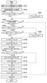
推定方法の一例を図3のフローチャートを参照しながら説明する。なお、図3に示される処理は、角速度センサ110の検出周期など、任意の所定の周期で繰り返し実行される。また任意のドリフト推定周期をEst_timeとする。
An example of the estimation method will be described with reference to the flowchart of FIG. Note that the processing shown in FIG. 3 is repeatedly executed at any predetermined period such as the detection period of the
まず、ステップS101において、ドリフト推定部113は、動きベクトル変換部109が出力する角度S1(一例としてYaw角ψv_int)を取得し、ステップS102へ進む。ステップS102において、ドリフト推定部113は、後述する姿勢演算部200が出力する角度S2(一例としてYaw角ψG_int)を取得し、ステップS103へ進む。
First, in step S101, the
ステップS103において、ドリフト推定部113は、動きベクトルエラー判定フラグV_flagがTRUEであるかFALSEであるかを判定する。そしてFALSEと判定された場合は、ステップS104へ進み、ドリフト推定部113は、ベクトルエラーカウントV_error_countをインクリメントする。TRUEと判定された場合は、ステップS105へ進む。
In step S103, the
ステップS105において、ドリフト推定部113は、処理されるタイミングが任意のドリフト推定周期Est_timeであるか判定する。そして任意のドリフト推定周期でない場合は、ステップS118へ進み、任意のドリフト推定周期であればステップS106へ進む。
In step S105, the
ステップS106において、ドリフト推定部113は、角度S1の絶対値を所定のリミット値S_Th1と比較して、リミット値S_Th1を超えているか否かを判定する。そして、角度S1の絶対値がリミット値S_Th1を超えていると判定された場合は、ステップS108へ進み、ドリフト推定部113は、ベクトルエラーカウントV_error_countをインクリメントする。ステップS106の判定において、角度S1の絶対値がリミット値S_Th1を超えていないと判定された場合はステップS107へ進む。
In step S106, the
ステップS107において、ドリフト推定部113は、角度S1の絶対値から角度S2の絶対値を引き、さらにその絶対値(以下、差の絶対値)を所定のリミット値S_Th2と比較して、リミット値S_Th2を超えているか否かを判定する。そして、差の絶対値がリミット値S_Th2を超えていると判定された場合は、ステップS108へ進み、ドリフト推定部113は、ベクトルエラーカウントV_error_countをインクリメントする。ステップS107の判定において、差の絶対値がリミット値S_Th2を超えていないと判定された場合はステップS109へ進む。
In step S107,
ステップS109において、ドリフト推定部113は、角度S1から前回のドリフト推定周期で取得した動きベクトル変換部109の出力値S1_oldを減算し、差分S1_diffを算出する。ステップS110において、ドリフト推定部113は、角度S2から前回のドリフト推定周期で取得した姿勢演算部200の出力値S2_oldを減算し、差分S2_diffを算出する。
In step S109, the
ステップS111において、ドリフト推定部113は、差分S2_diffから差分S1_diffを減算し、ドリフト推定周期で除算してドリフト推定微分値Drift_diffを算出する。
In step S111, the
ステップS112において、ドリフト推定部113は、ベクトルエラーカウントV_error_countが0であるか否かを判定する。そして0であると判定された場合にはステップS113へ進み、0以外と判定された場合はステップS115へ進む。
In step S112, the
ステップS113において、ドリフト推定部113は、前回のドリフト推定周期で算出したドリフト推定値Drift_oldと、ドリフト推定微分値Drift_diffを加算し、ドリフト推定値Driftを算出する。ステップS114において、ドリフト推定部113は、前回のドリフト推定周期で算出したドリフト推定値Drift_oldを、今回のドリフト推定周期で算出した、ドリフト推定値Driftへ更新する。
In step S113, the
ステップS115において、ドリフト推定部113は、角度S1_oldを、今回のドリフト推定周期で取得した角度S1に更新する。ステップS116において、ドリフト推定部113は、角度S2_oldを、今回のドリフト推定周期で取得した角度S2に更新する。
In step S115, the
ステップS117において、ドリフト推定部113は、ベクトルエラーカウントV_error_countを初期値0に更新する。ステップS118において、ドリフト推定部113は、今回のドリフト推定周期で算出した、ドリフト推定値Driftを出力する。
In step S117, the
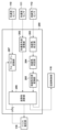
次に、図4のブロック図を用いて、姿勢演算部200について説明する。角速度角度変換部201は、角速度センサ110から出力される角速度データを、回転角度へ変換する。まず、角速度センサ110から出力される角速度データ(ωy,ωx,ωz)はセンサ座標系であるため、(式3)を用いて、絶対座標系(オイラー角)の角速度(回転角度の微分値)(ψ・G,θ・G,φ・G)へ変換する。その後、所定の積分時間をtとし、(式3)の結果をそれぞれ積分することによりY軸回りの絶対回転角度Yaw角、X軸回りの絶対回転角度Pitch角、Z軸回りの絶対回転角度Roll角(ψG,θG,φG)を算出する(式4、式5、式6)。算出したそれぞれの絶対角度(ψG,θG,φG)は、後述する姿勢角演算部206へ出力される。
Next, the

加速度角度変換部202は、加速度センサ111から出力される加速度データを回転角度へ変換する。静止時において、加速度センサは重力加速度のみを検出することから、重力加速度をg(静止時の垂直方向加速度)、Y軸回りの絶対回転角度Yaw角、X軸回りの絶対回転角度Pitch角、Z軸回りの絶対回転角度Roll角をそれぞれ(ψ,θ,φ)とし、加速度センサ111から取得したY軸方向、X軸方向、Z軸方向の加速度データをそれぞれ(Ay,Ax,Az)とすると、(式7)(式8)が成り立つ。
The acceleration

(式8)は、センサ座標系から絶対座標系へ変換する回転行列である。(式7)を展開し、加速度データから求めたX軸回り、Z軸回りの回転角をそれぞれ(θA,φA)とすると、(式9)(式10)(式11)の関係が得られる。算出したそれぞれの絶対角度(θA,φA)は、後述する姿勢角演算部206へ出力される。
(Equation 8) is a rotation matrix for transforming from the sensor coordinate system to the absolute coordinate system. By expanding (Equation 7) and letting the rotation angles around the X-axis and Z-axis obtained from the acceleration data be (θA, φA), the relationships of (Equation 9), (Equation 10) and (Equation 11) are obtained. . Each of the calculated absolute angles (θA, φA) is output to the

地磁気校正部203は、地磁気センサ112から出力される地磁気データから、地磁気センサの校正を行う。地磁気センサの校正はキャリブレーションと呼ばれ、地磁気センサのキャリブレーション方法の一例として、地磁気センサを水平及び垂直に回転させ、磁気歪みとオフセットを除去する方法がある。この方法では、地磁気センサの出力から感度を求めることにより磁気歪みを除去し、原点を求めることによりオフセットを除去できる。また、キャリブレーションを行ってもその後、強い磁場の影響を受けて撮像装置内の着磁状態が変化する。詳しいキャリブレーション方法については、公知の技術であるため説明は省略する。
The
キャリブレーションが完了したら、地磁気判定結果M_CalibrationをTRUE、否であればFLASEとし、また磁気歪み補正後及びオフセット補正後の地磁気データを(My,Mx,Mz)として地磁気判定部204へ出力する。 When the calibration is completed, the geomagnetism determination result M_Calibration is set to TRUE, and if not, it is set to FLASE.
地磁気判定部204は、地磁気校正部203の出力から地磁気データの信頼性判定を行う。信頼性判定方法の一例を図5のフローチャートを参照しながら説明する。なお、図5に示される処理は、地磁気センサ112の検出周期など、任意の所定の周期で繰り返し実行される。
A
まず、ステップS201において、地磁気判定部204は、地磁気校正部203が出力する各軸の地磁気データ(My,Mx,Mz)を取得し、ステップS202へ進む。ステップS202において、地磁気判定部204は、地磁気判定結果M_Calibrationを取得し、ステップS203へ進む。
First, in step S201, the
ステップS203において、地磁気判定部204は、地磁気判定結果M_CalibrationがTrueであるかFALSEであるかを判定し、そしてFALSEと判定された場合は、ステップS205へ進む。ステップS203の判定において、TRUEと判定された場合は、ステップS204へ進む。
In step S203, the
ステップS204において、地磁気判定部204は、各軸の地磁気データ(My,Mx,Mz)を三平方の定理を用いて合成し、合成したデータ(以下、合成データ)を所定のリミット値M_Th1と比較して、M_Th1を超えているか否かを判定する。そして、合成データがリミット値M_Th1を超えている(信頼性が所定値よりも低い)と判定された場合は、ステップS205へ進む。ステップS204の判定において、合成データがリミット値M_Th1を超えていない(信頼性が所定値以上)と判定された場合はステップS206へ進む。
In step S204, the
ステップS205において、地磁気判定部204は、地磁気判定結果M_CalibrationをFALSEとする。また、地磁気センサ112の検出値の信頼性が低いことを、表示デバイス115などを用いてユーザーに通知する。ステップS206において、地磁気判定部204は、地磁気校正部203が出力する各軸の地磁気データ(My,Mx,Mz)と、地磁気判定結果M_Calibrationとを後述する姿勢角演算部206へ出力する。
In step S205, the
図4の説明に戻って、地磁気角度変換部205は、地磁気判定部204から出力される地磁気データ(My,Mx,Mz)を、後述する姿勢角演算部206の姿勢角出力(θ,φ)を用いて、回転角度へ変換する。地磁気センサは、センサが水平である場合に方位角、つまり垂直方向の回転軸Y(Yaw軸)回りの絶対角度を算出できる。しかしセンサが水平でない場合には磁場を正確に検出できないため誤差が生じる。この水平でないことにより生じる誤差は、絶対角Pitch角θとRoll角φを用いて修正できる。地磁気判定部204から取得したY軸方向、X軸方向、Z軸方向の地磁気データをそれぞれ(My,Mx,Mz)、誤差を補正したY軸方向、X軸方向、Z軸方向の地磁気データをそれぞれ(My_com,Mx_com,Mz_com)、回転角度へ変換したYaw角をψMとすると、(式12)(式13)の関係が得られる。算出した回転角度ψMは、後述する姿勢角演算部206へ出力される。
Returning to the description of FIG. 4, the geomagnetic

姿勢角演算部206は、角速度角度変換部201、加速度角度変換部202、地磁気角度変換部205から出力されるデータから、カルマンフィルタを用いてセンサフュージョンを行い、姿勢角を算出する。今回、カルマンフィルタは、推定したい値を状態値とし、センサ等から得られる情報を入力値と観測値とし、システム行列を設定する。なお、カルマンフィルタは、状態方程式(式14)及び観測方程式(式15)からリアルタイムに最適な状態値を推定し続けることができるフィルタであり、詳しい内容は公知であるため説明を省略する。今回は、xを状態値、yを観測値、uを入力値、システム行列をA、B、Cとする。なお、添え字tは時点を表す。
Posture
x(t+1)=A(t)x(t)+B(t)u(t)+m(t) …(式14)
y(t)=C(t)x(t)+n(t) …(式15)
姿勢角演算方法の一例を図6のフローチャートを参照しながら説明する。なお、図6に示される処理は、各センサの検出周期など、任意の所定の周期で繰り返し実行される。
x(t+1)=A(t)x(t)+B(t)u(t)+m(t) (Formula 14)
y(t)=C(t)x(t)+n(t) (Formula 15)
An example of the attitude angle calculation method will be described with reference to the flowchart of FIG. Note that the processing shown in FIG. 6 is repeatedly executed at any predetermined cycle such as the detection cycle of each sensor.
まず、ステップS301において、姿勢角演算部206は、角速度センサ110から出力される角速度データからドリフト推定値Driftを減算した角速度(ωy,ωx,ωz)と、角速度角度変換部201から出力されるY軸回り、X軸回り、Z軸回りそれぞれの回転角(ψG,θG,φG)を取得し、ステップS302へ進む。
First, in step S<b>301 , the attitude
ステップS302において、姿勢角演算部206は、加速度角度変換部202から出力されるX軸回り、Z軸回りそれぞれの回転角(θA,φA)を取得し、ステップS303へ進む。ステップS303において、姿勢角演算部206は、地磁気角度変換部205から出力されるYaw角ψMを取得し、ステップS304へ進む。
In step S302, the
ステップS304において、姿勢角演算部206は、撮像システム100が起動されてから初めて行う処理であるか否かを判定する。そして否であると判定された場合にはステップS306へ進み、初めて行う処理と判定された場合はステップS305へ進む。
In step S304, the posture
ステップS305において、姿勢角演算部206は、カルマンフィルタの各初期パラメータをセットする。初期のカルマンフィルタ状態値にステップS301で取得した回転角(ψG,θG,φG)を設定する。観測値及び推定後の姿勢角(ψEst,θEst,φEst)の初期値としてステップS302で取得した回転角(θA,φA)と、ステップS303で取得したYaw角ψMを設定し、入力値にステップS301で取得した角速度(ωy,ωx,ωz)を設定する。システム行列A(t)、B(t)、C(t)を、(式16)(式17)のように設定する。その他、カルマンゲインKの初期値やプロセスノイズm、観測ノイズn、誤差共分散行列Pについては、それぞれ構築したシステムに適するゲイン、白色ガウスノイズ、センサノイズ、推定誤差量からそれぞれ設定し、ステップS307へ進む。
In step S305, the

ステップS306において、姿勢角演算部206は、カルマンフィルタのパラメータをセットする。カルマンフィルタ状態値にステップS301で取得した回転角(ψG,θG,φG)を設定する。観測値にステップS302で取得した回転角(θA,φA)と、ステップS303で取得したYaw角ψMを設定し、入力値にステップS301で取得した角速度(ωy,ωx,ωz)を設定する。システム行列A(t)、B(t)、C(t)を(式16)(式17)のように設定し、(ψEst(t),θEst(t),φEst(t))は前回の周期で推定した姿勢角を用いる。その他、プロセスノイズm、観測ノイズnについては、それぞれ構築したシステムに適する白色ガウスノイズ、センサノイズから設定し、ステップS307へ進む。
In step S306, the attitude
ステップS307において、姿勢角演算部206は、カルマンフィルタを用いて、姿勢角となる状態値(ψEst,θEst,φEst)を推定する。カルマンフィルタは、現時点での推定値が得られており、その情報から離散状態方程式を用いて次のフェーズでの推定値を予測する予測フェーズと、予測フェーズの後に実際にセンサより得られた測定値から、予測していた推定値の補正を掛ける更新フェーズに分けられる。まず、予測フェーズでは、現時点での状態値から次の推定値を推定し(式18)、予測誤差の共分散を算出する(式19)。次に更新フェーズへ進み、カルマンゲインを更新し(式20)、予測フェーズで推定した推定値を測定値で補正する(式21)。次に状態予測誤差の共分散を算出し(式22)、ステップS308へ進む。また、プロセスノイズmに関する共分散行列をQ、観測ノイズnに関する共分散行列をRとする。
In step S307, the posture

上記の予測フェーズと更新フェーズを繰り返すことにより、常に姿勢角となる状態値を推定できる。 By repeating the prediction phase and the update phase, it is possible to estimate the state value that is always the attitude angle.
ステップS308において、姿勢角演算部206は、地磁気判定結果M_CalibrationがTrueであるかFALSEであるかを判定し、そしてTRUEと判定された場合は、地磁気センサ112の検出値を姿勢角の算出に用いることに決定し、ステップS309へ進む。ステップS308の判定において、FALSEと判定された場合は、ステップS310へ進む。
In step S308, the posture
ステップS309において、ステップS307で推定した姿勢角(ψEst,θEst,φEst)を出力する。ステップS310において、ステップS301で取得したψGとステップS307で推定した姿勢角(θEst,φEst)を出力する。 At step S309, the attitude angles (ψEst, θEst, φEst) estimated at step S307 are output. In step S310, ψG obtained in step S301 and the attitude angles (θEst, φEst) estimated in step S307 are output.
以上説明したように、本実施形態によれば、金属の物体を近づける、地磁気が得られない場所へ移動する、地磁気センサがキャリブレーションされていないなど、地磁気センサの出力値を正確に得られない状況でも、姿勢角誤差をドリフト量として推定することにより正しい姿勢角を算出することが可能となる。算出された姿勢角は、画像に関連付けて記録される。 As described above, according to the present embodiment, the output value of the geomagnetic sensor cannot be obtained accurately when a metal object is approached, when the geomagnetism is not obtained, when the geomagnetic sensor is not calibrated, or when the geomagnetic sensor is not calibrated. Even under such circumstances, it is possible to calculate the correct attitude angle by estimating the attitude angle error as the amount of drift. The calculated attitude angle is recorded in association with the image.
なお、姿勢角誤差をドリフト量として推定し、除去する方法はこれに限らず、動きベクトルから相補フィルタやカルマンフィルタを用いて角速度を算出する方法で誤差を除去してもよく、角度としてドリフト量を推定し除去する方法に限定されるものではない。 Note that the method of estimating the attitude angle error as a drift amount and removing it is not limited to this, and the error may be removed by a method of calculating the angular velocity from the motion vector using a complementary filter or a Kalman filter. It is not limited to the method of estimating and removing.
(第2の実施形態)
図7は、本発明の第2の実施形態に係わる撮像システム150の構成を示すブロック図である。なお、図1と同様の構成には同じ符号を付し、説明は省略する。図7は、図1の構成に対し、ドリフト推定部113が削除され、ドリフト推定部113とは異なる制御のドリフト推定部118が追加された構成となっている。また、図1の姿勢演算部200が内部構成の異なる姿勢演算部250となっている。以下、図8のブロック図を用いて、本実施形態における姿勢演算部250の構成と、その動作について具体的に説明する。なお図8において、図4と同様の構成には同じ符号を付し、説明は省略する。図8の姿勢演算部250の構成は、図4の構成に対し、角速度角度変換部201が削除され、クォータニオン変換部207が追加された構成となっている。
(Second embodiment)
FIG. 7 is a block diagram showing the configuration of an
第1の実施形態では、角速度角度変換部201において、角速度センサ110から出力される角速度データから、回転角度へ変換する際に、オイラー角を用いて変換を行う方法について説明した。しかしオイラー角は、Pitch角が±90°である垂直となる場合に(式3)に含まれるsecθ及びtanθの値が∞となり計算不能に陥り、また±90°へ接近するほど誤差が大きくなる特異点問題が発生する。そのため、角度を持たないクォータニオンを使うことにより、特異点問題の影響を受けることなく撮像装置の姿勢演算を行う。クォータニオンは、4次元で3次元空間の回転を行い、(式23)で示すように3つの虚数i,j,kを持つ複素数である。
In the first embodiment, a method of converting the angular velocity data output from the
q=q1i+q2j+q3k+q4 …(式23)
図8において、クォータニオン変換部207は、角速度センサ110から出力される角速度データと、ドリフト推定部118から出力されるデータを、姿勢角演算部206から出力される姿勢角データから差し引いたデータを、回転角度へ変換する。まず、姿勢角演算部206から出力される姿勢角データからドリフト推定部118のデータを差し引いたデータを(ψEst_q,θEst_q,φEst_q)とすると、(式24)を用いてクォータニオンへ変換できる。その後、角速度センサ110から出力されるY軸回り、X軸回り、Z軸回りの角速度データを(ωy,ωx,ωz)とし、(式25)を用いて角速度からクォータニオンへ変換する。所定の積分時間をtとし、(式25)で求めたクォータニオンを積分した値を(式26)の回転行列を用いてオイラー角(ψG,θG,φG)へ変換し、姿勢角演算部206へ出力する。
q=q1i+q2j+q3k+q4 (Formula 23)
In FIG. 8, the

しかしながら、姿勢角演算部206で、クォータニオン変換部207、加速度角度変換部202、地磁気角度変換部205の出力から姿勢角を演算する際に、地磁気角度変換部205の出力が正確でない場合がある。したがって、地磁気角度変換部205の出力を使わない場合には(式25)で求めたクォータニオンを積分する際の誤差が蓄積されることになる。
However, when the posture
そこで、本実施形態の撮像システム150では、後述するドリフト推定部118において、動きベクトル変換部109の出力と、姿勢角演算部206の出力とから、演算した姿勢角のドリフト量を推定する。
Therefore, in the
ドリフト推定部118について説明する。なお、Yaw角とPitch角の処理は同じとなるので、いずれか一方の制御に関してのみ説明を行う。また、ドリフト推定部118は、動きベクトル変換部109の出力と、姿勢角演算部206の出力とから、姿勢角誤差をドリフト量として推定する。
The
演算誤差が生じる要因として、角速度センサの検出誤差が挙げられる。推定方法の一例を図9のフローチャートを参照しながら説明する。図9において、図3と同様の構成には同じ符号を付し、説明は省略する。なお、図9に示される処理は、角速度センサ110の検出周期など、任意の所定の周期で繰り返し実行される。また任意のドリフト推定周期をEst_timeとする。
A detection error of an angular velocity sensor can be cited as a cause of calculation error. An example of the estimation method will be described with reference to the flowchart of FIG. In FIG. 9, the same components as those in FIG. 3 are denoted by the same reference numerals, and descriptions thereof are omitted. The processing shown in FIG. 9 is repeatedly executed at any predetermined period such as the detection period of
ステップS105において、ドリフト推定部118は、処理されるタイミングが任意のドリフト推定周期Est_timeであるか否かを判定する。そして任意のドリフト推定周期でない場合は、ステップS119へ進み、任意のドリフト推定周期であればステップS106へ進む。
In step S105, the
ステップS107において、ドリフト推定部118は、角度S1の絶対値から角度S2の絶対値を引き、さらにその絶対値(以下、差分絶対値)を所定のリミット値S_Th3と比較して、リミット値S_Th3を超えているか否かを判定する。そしてリミット値S_Th3を超えていると判定された場合は、ステップS108へ進み、ドリフト推定部118は、ベクトルエラーカウントV_error_countをインクリメントする。
In step S107, the
ステップS107の判定において、ドリフト推定部118は、差分絶対値がリミット値S_Th3を超えていないと判定された場合はステップS112へ進む。ステップS112において、ドリフト推定部118は、ベクトルエラーカウントV_error_countが0であるか否かを判定する。そして0であると判定された場合にはステップS120へ進み、0以外と判定された場合はステップS119へ進む。
If the
ステップS119において、ドリフト推定部118は、ドリフト推定値Driftを0とする。ステップS120において、ドリフト推定部118は、角度S2から角度S1を減算し、ドリフト推定値Driftを算出する。
In step S119, the
ステップS117において、ドリフト推定部118は、ベクトルエラーカウントV_error_countを初期値0に更新する。ステップS118において、今回のドリフト推定周期で算出した、ドリフト推定値Driftを出力する。
In step S117, the
以上説明したように、本実施形態によれば、金属の物体を近づける、地磁気が得られない場所へ移動する、地磁気センサがキャリブレーションされていないなど、地磁気センサの出力値を正確に得られない状況でも、姿勢角誤差をドリフト量として推定することにより正しい姿勢角を算出することが可能となる。 As described above, according to the present embodiment, the output value of the geomagnetic sensor cannot be obtained accurately when a metal object is approached, when the geomagnetism is not obtained, when the geomagnetic sensor is not calibrated, or when the geomagnetic sensor is not calibrated. Even under such circumstances, it is possible to calculate the correct attitude angle by estimating the attitude angle error as the amount of drift.
なお、本実施形態では、クォータニオンを用いて姿勢角を算出することにより、演算途中のオイラー角がわかりにくくなるものの、Pitch角が±90°の垂直な場合でも演算が可能となる。 In the present embodiment, by calculating the attitude angle using quaternions, it is possible to calculate even when the pitch angle is perpendicular to ±90°, although the Euler angle during calculation becomes difficult to understand.
なお、上記の各実施形態では、姿勢角演算手段の一例としてカルマンフィルタを用いる場合について説明したが、その他の演算手法を用いてもよい。例えば、センサの周波数特性に着目し、低周波特性がよいセンサと高周波特性がよいセンサを組み合わせて、センサ単体よりも周波数領域特性を向上させる相補フィルタを用いてもよい。また、次の状態の確率密度推定にモンテカルロ法を用いるパーティクルフィルタを用いてもよい。 In each of the above-described embodiments, the case of using the Kalman filter as an example of the attitude angle calculation means has been described, but other calculation methods may be used. For example, focusing on the frequency characteristics of the sensors, a complementary filter may be used that improves the frequency domain characteristics compared to a single sensor by combining a sensor with good low frequency characteristics and a sensor with good high frequency characteristics. Also, a particle filter that uses the Monte Carlo method for estimating the probability density of the next state may be used.
(他の実施形態)
また本発明は、上述の実施形態の1以上の機能を実現するプログラムを、ネットワーク又は記憶媒体を介してシステム又は装置に供給し、そのシステム又は装置のコンピュータにおける1つ以上のプロセッサーがプログラムを読出し実行する処理でも実現できる。また、1以上の機能を実現する回路(例えば、ASIC)によっても実現できる。
(Other embodiments)
In addition, the present invention supplies a program that implements one or more functions of the above-described embodiments to a system or apparatus via a network or a storage medium, and one or more processors in the computer of the system or apparatus reads the program. It can also be realized by executing processing. It can also be implemented by a circuit (eg, ASIC) that implements one or more functions.
例えば、撮像装置から角速度情報、加速度情報、動きベクトル情報を取得した姿勢角算出装置のCPUなどの算出回路が撮像装置の姿勢角を算出し、算出した姿勢角情報を撮像装置に送信するようにしてもよい。すなわち、撮像装置の姿勢角を算出する算出回路を撮像装置とは異なる姿勢角算出装置が有していてもよい。 For example, a calculation circuit such as a CPU of an attitude angle calculation device that acquires angular velocity information, acceleration information, and motion vector information from an imaging device calculates the attitude angle of the imaging device, and transmits the calculated attitude angle information to the imaging device. may That is, an attitude angle calculation device different from the imaging device may have a calculation circuit for calculating the attitude angle of the imaging device.
発明は上記実施形態に制限されるものではなく、発明の精神及び範囲から離脱することなく、様々な変更及び変形が可能である。従って、発明の範囲を公にするために請求項を添付する。 The invention is not limited to the embodiments described above, and various modifications and variations are possible without departing from the spirit and scope of the invention. Accordingly, the claims are appended to make public the scope of the invention.
100,150:撮像システム、101:撮像レンズ、104:フォーカスレンズ、105:撮像素子、108:動きベクトル検出部、109:動きベクトル変換部、110:角速度センサ、111:加速度センサ、112:地磁気センサ、113,118ドリフト推定部、200,250:姿勢演算部 100, 150: imaging system, 101: imaging lens, 104: focus lens, 105: imaging element, 108: motion vector detector, 109: motion vector converter, 110: angular velocity sensor, 111: acceleration sensor, 112: geomagnetic sensor , 113, 118 drift estimator, 200, 250: attitude calculator
Claims (15)
前記撮像装置の動きの角速度を検出する角速度検出手段と、
前記撮像装置の動きの加速度を検出する加速度検出手段と、
前記撮像装置で撮像された画像に基づいて動きベクトルを検出する動きベクトル検出手段と、
前記角速度検出手段の検出値と、前記加速度検出手段の検出値と、前記動きベクトル検出手段の検出値とに基づいて前記撮像装置の姿勢角を算出する算出手段と、を備え、
前記算出手段は、前記動きベクトル検出手段により得られた検出値を用いて前記角速度検出手段の出力を補正し、補正した値に基づいて前記撮像装置の姿勢角を算出することを特徴とする撮像装置。 An imaging device,
angular velocity detection means for detecting an angular velocity of movement of the imaging device;
Acceleration detection means for detecting acceleration of movement of the imaging device;
motion vector detection means for detecting a motion vector based on the image captured by the imaging device;
calculating means for calculating the posture angle of the imaging device based on the detection value of the angular velocity detection means, the detection value of the acceleration detection means, and the detection value of the motion vector detection means;
The calculating means corrects the output of the angular velocity detecting means using the detected value obtained by the motion vector detecting means, and calculates the attitude angle of the imaging device based on the corrected value. Device.
前記撮像装置の動きの角速度を検出する角速度検出工程と、
前記撮像装置の動きの加速度を検出する加速度検出工程と、
前記撮像装置で撮像された画像に基づいて動きベクトルを検出する動きベクトル検出工程と、
前記角速度検出工程の検出値と、前記加速度検出工程の検出値と、前記動きベクトル検出工程の検出値とに基づいて前記撮像装置の姿勢角を算出する算出工程と、を有し、
前記算出工程では、前記動きベクトル検出工程において得られた検出値を用いて前記角速度検出工程の出力を補正し、補正した値に基づいて前記撮像装置の姿勢角を算出することを特徴とする撮像装置の制御方法。 A control method for an imaging device,
an angular velocity detection step of detecting an angular velocity of movement of the imaging device;
an acceleration detection step of detecting acceleration of movement of the imaging device;
a motion vector detection step of detecting a motion vector based on the image captured by the imaging device;
a calculating step of calculating an attitude angle of the imaging device based on the detected value of the angular velocity detecting step, the detected value of the acceleration detecting step, and the detected value of the motion vector detecting step;
In the calculating step, the detected value obtained in the motion vector detecting step is used to correct the output of the angular velocity detecting step, and the posture angle of the imaging device is calculated based on the corrected value. How to control the device.
前記撮像装置の動きの加速度情報を取得する加速度取得手段と、
前記撮像装置で撮像された画像に基づく動きベクトル情報を取得する動きベクトル取得手段と、
前記角速度取得手段により取得した角速度情報と、前記加速度取得手段により取得した加速度情報と、前記動きベクトル取得手段により取得した動きベクトル情報とに基づいて前記撮像装置の姿勢角を算出する算出手段と、を備え、
前記算出手段は、前記動きベクトル検出手段により取得した動きベクトル情報を用いて前記角速度取得手段により取得した角速度情報を補正し、補正した情報に基づいて前記撮像装置の姿勢角を算出することを特徴とする姿勢角算出装置。 angular velocity acquisition means for acquiring angular velocity information of the movement of the imaging device;
acceleration acquisition means for acquiring acceleration information of movement of the imaging device;
motion vector acquisition means for acquiring motion vector information based on an image captured by the imaging device;
calculating means for calculating the attitude angle of the imaging device based on the angular velocity information obtained by the angular velocity obtaining means, the acceleration information obtained by the acceleration obtaining means, and the motion vector information obtained by the motion vector obtaining means; with
The calculating means corrects the angular velocity information obtained by the angular velocity obtaining means using the motion vector information obtained by the motion vector detecting means, and calculates the attitude angle of the imaging device based on the corrected information. Attitude angle calculation device.
Priority Applications (2)
| Application Number | Priority Date | Filing Date | Title |
|---|---|---|---|
| JP2019083211A JP7240241B2 (en) | 2019-04-24 | 2019-04-24 | Imaging device and its control method, attitude angle calculation device, program, storage medium |
| US16/845,679 US11361465B2 (en) | 2019-04-24 | 2020-04-10 | Image capturing apparatus and control method thereof, and orientation angle calculation apparatus for estimating orientation of image capturing apparatus |
Applications Claiming Priority (1)
| Application Number | Priority Date | Filing Date | Title |
|---|---|---|---|
| JP2019083211A JP7240241B2 (en) | 2019-04-24 | 2019-04-24 | Imaging device and its control method, attitude angle calculation device, program, storage medium |
Publications (3)
| Publication Number | Publication Date |
|---|---|
| JP2020181059A JP2020181059A (en) | 2020-11-05 |
| JP2020181059A5 JP2020181059A5 (en) | 2022-04-26 |
| JP7240241B2 true JP7240241B2 (en) | 2023-03-15 |
Family
ID=72917219
Family Applications (1)
| Application Number | Title | Priority Date | Filing Date |
|---|---|---|---|
| JP2019083211A Active JP7240241B2 (en) | 2019-04-24 | 2019-04-24 | Imaging device and its control method, attitude angle calculation device, program, storage medium |
Country Status (2)
| Country | Link |
|---|---|
| US (1) | US11361465B2 (en) |
| JP (1) | JP7240241B2 (en) |
Families Citing this family (1)
| Publication number | Priority date | Publication date | Assignee | Title |
|---|---|---|---|---|
| CN117122262A (en) * | 2023-04-11 | 2023-11-28 | 深圳信息职业技术学院 | Positioning method for endoscope acquired image and endoscope system |
Citations (4)
| Publication number | Priority date | Publication date | Assignee | Title |
|---|---|---|---|---|
| WO2009150793A1 (en) | 2008-06-09 | 2009-12-17 | パナソニック株式会社 | Imaging device and imaging method |
| JP2011139169A (en) | 2009-12-25 | 2011-07-14 | Canon Inc | Imaging apparatus |
| JP2012173301A (en) | 2011-02-17 | 2012-09-10 | Nikon Corp | Shake correcting device and optical apparatus |
| JP2015114438A (en) | 2013-12-10 | 2015-06-22 | キヤノン株式会社 | Image processor, imaging device provided with the same, and image processing method |
Family Cites Families (10)
| Publication number | Priority date | Publication date | Assignee | Title |
|---|---|---|---|---|
| US20050168597A1 (en) * | 2004-02-04 | 2005-08-04 | Clay Fisher | Methods and apparatuses for formatting and displaying content |
| JP4422777B2 (en) * | 2008-08-05 | 2010-02-24 | オリンパス株式会社 | Moving body posture detection device |
| US10165276B2 (en) * | 2010-09-30 | 2018-12-25 | Texas Instruments Incorporated | Method and apparatus for frame coding in vertical raster scan order for HEVC |
| JP5121911B2 (en) * | 2010-10-19 | 2013-01-16 | キヤノン株式会社 | Anti-shake control device, imaging device, and anti-shake control method |
| JP5061264B1 (en) | 2012-03-23 | 2012-10-31 | 国立大学法人 千葉大学 | Small attitude sensor |
| JP6152511B2 (en) * | 2013-03-29 | 2017-06-28 | 株式会社メガチップス | Portable terminal device, program, and correction method |
| JP6332212B2 (en) * | 2015-09-18 | 2018-05-30 | カシオ計算機株式会社 | Posture estimation apparatus, posture estimation method, and program |
| JP6585995B2 (en) * | 2015-11-06 | 2019-10-02 | クラリオン株式会社 | Image processing system |
| FR3048783B1 (en) * | 2016-03-11 | 2018-04-06 | Commissariat A L'energie Atomique Et Aux Energies Alternatives | METHOD FOR DETECTING ANOMALY IN THE CONTEXT OF THE USE OF A MAGNETIC LOCATION DEVICE |
| US10726569B2 (en) * | 2017-05-16 | 2020-07-28 | Canon Kabushiki Kaisha | Information processing apparatus, information processing method, and non-transitory computer-readable storage medium |
-
2019
- 2019-04-24 JP JP2019083211A patent/JP7240241B2/en active Active
-
2020
- 2020-04-10 US US16/845,679 patent/US11361465B2/en active Active
Patent Citations (4)
| Publication number | Priority date | Publication date | Assignee | Title |
|---|---|---|---|---|
| WO2009150793A1 (en) | 2008-06-09 | 2009-12-17 | パナソニック株式会社 | Imaging device and imaging method |
| JP2011139169A (en) | 2009-12-25 | 2011-07-14 | Canon Inc | Imaging apparatus |
| JP2012173301A (en) | 2011-02-17 | 2012-09-10 | Nikon Corp | Shake correcting device and optical apparatus |
| JP2015114438A (en) | 2013-12-10 | 2015-06-22 | キヤノン株式会社 | Image processor, imaging device provided with the same, and image processing method |
Also Published As
| Publication number | Publication date |
|---|---|
| US20200342618A1 (en) | 2020-10-29 |
| JP2020181059A (en) | 2020-11-05 |
| US11361465B2 (en) | 2022-06-14 |
Similar Documents
| Publication | Publication Date | Title |
|---|---|---|
| JP6663040B2 (en) | Depth information acquisition method and apparatus, and image acquisition device | |
| JP6209002B2 (en) | Imaging apparatus and control method thereof | |
| US8264553B2 (en) | Hardware assisted image deblurring | |
| EP2640058B1 (en) | Image processing device, image processing method, program, and imaging device | |
| Hanning et al. | Stabilizing cell phone video using inertial measurement sensors | |
| JP3428539B2 (en) | Satellite attitude sensor calibration device | |
| US8310563B2 (en) | Imaging apparatus, imaging method, and program | |
| JP5027746B2 (en) | POSITION MEASUREMENT METHOD, POSITION MEASUREMENT DEVICE, AND PROGRAM | |
| US20100149368A1 (en) | Imaging apparatus, imaging method, and program | |
| US20100141735A1 (en) | Imaging apparatus, imaging method, and program | |
| CN108827341B (en) | Method for determining a deviation in an inertial measurement unit of an image acquisition device | |
| JP2016525842A (en) | Method for camera motion prediction and correction | |
| JP2010014450A (en) | Position measurement method, position measurement device, and program | |
| JP2017147682A (en) | Imaging system for entire celestial sphere | |
| JP2013148717A (en) | Shake amount detecting device, imaging apparatus, and shake amount detection method | |
| US10623644B2 (en) | Image pick-up apparatus and control method thereof | |
| US11196929B2 (en) | Signal processing device, imaging device, and signal processing method | |
| JP7240241B2 (en) | Imaging device and its control method, attitude angle calculation device, program, storage medium | |
| JP6725106B2 (en) | Imaging device | |
| JP7017961B2 (en) | Blur correction device and blur correction method | |
| US9210384B2 (en) | System and method for real time registration of images | |
| JP2012237884A (en) | Blur correction device and optical instrument | |
| JP2020061770A (en) | Entire-celestial-sphere image generation method, entire-celestial-sphere image generation and display method, program for entire-celestial-sphere image generation system, and program for entire-celestial-sphere image generation and display system | |
| JP2015049446A (en) | Imaging device | |
| US11282223B2 (en) | Signal processing apparatus, signal processing method, and imaging apparatus |
Legal Events
| Date | Code | Title | Description |
|---|---|---|---|
| RD01 | Notification of change of attorney |
Free format text: JAPANESE INTERMEDIATE CODE: A7421 Effective date: 20210103 |
|
| A521 | Request for written amendment filed |
Free format text: JAPANESE INTERMEDIATE CODE: A523 Effective date: 20210113 |
|
| A521 | Request for written amendment filed |
Free format text: JAPANESE INTERMEDIATE CODE: A523 Effective date: 20220418 |
|
| A621 | Written request for application examination |
Free format text: JAPANESE INTERMEDIATE CODE: A621 Effective date: 20220418 |
|
| A977 | Report on retrieval |
Free format text: JAPANESE INTERMEDIATE CODE: A971007 Effective date: 20230125 |
|
| TRDD | Decision of grant or rejection written | ||
| A01 | Written decision to grant a patent or to grant a registration (utility model) |
Free format text: JAPANESE INTERMEDIATE CODE: A01 Effective date: 20230203 |
|
| A61 | First payment of annual fees (during grant procedure) |
Free format text: JAPANESE INTERMEDIATE CODE: A61 Effective date: 20230303 |
|
| R151 | Written notification of patent or utility model registration |
Ref document number: 7240241 Country of ref document: JP Free format text: JAPANESE INTERMEDIATE CODE: R151 |