JP7236171B2 - propeller - Google Patents
propeller Download PDFInfo
- Publication number
- JP7236171B2 JP7236171B2 JP2021553714A JP2021553714A JP7236171B2 JP 7236171 B2 JP7236171 B2 JP 7236171B2 JP 2021553714 A JP2021553714 A JP 2021553714A JP 2021553714 A JP2021553714 A JP 2021553714A JP 7236171 B2 JP7236171 B2 JP 7236171B2
- Authority
- JP
- Japan
- Prior art keywords
- propeller
- obstacle
- hub
- lift
- propellers
- Prior art date
- Legal status (The legal status is an assumption and is not a legal conclusion. Google has not performed a legal analysis and makes no representation as to the accuracy of the status listed.)
- Active
Links
Images


Classifications
-
- B—PERFORMING OPERATIONS; TRANSPORTING
- B63—SHIPS OR OTHER WATERBORNE VESSELS; RELATED EQUIPMENT
- B63H—MARINE PROPULSION OR STEERING
- B63H1/00—Propulsive elements directly acting on water
- B63H1/02—Propulsive elements directly acting on water of rotary type
- B63H1/12—Propulsive elements directly acting on water of rotary type with rotation axis substantially in propulsive direction
- B63H1/14—Propellers
- B63H1/26—Blades
-
- B—PERFORMING OPERATIONS; TRANSPORTING
- B64—AIRCRAFT; AVIATION; COSMONAUTICS
- B64C—AEROPLANES; HELICOPTERS
- B64C11/00—Propellers, e.g. of ducted type; Features common to propellers and rotors for rotorcraft
- B64C11/02—Hub construction
- B64C11/04—Blade mountings
- B64C11/08—Blade mountings for non-adjustable blades
- B64C11/12—Blade mountings for non-adjustable blades flexible
-
- B—PERFORMING OPERATIONS; TRANSPORTING
- B64—AIRCRAFT; AVIATION; COSMONAUTICS
- B64C—AEROPLANES; HELICOPTERS
- B64C11/00—Propellers, e.g. of ducted type; Features common to propellers and rotors for rotorcraft
- B64C11/16—Blades
- B64C11/20—Constructional features
-
- B—PERFORMING OPERATIONS; TRANSPORTING
- B64—AIRCRAFT; AVIATION; COSMONAUTICS
- B64C—AEROPLANES; HELICOPTERS
- B64C27/00—Rotorcraft; Rotors peculiar thereto
- B64C27/32—Rotors
- B64C27/35—Rotors having elastomeric joints
-
- B—PERFORMING OPERATIONS; TRANSPORTING
- B64—AIRCRAFT; AVIATION; COSMONAUTICS
- B64C—AEROPLANES; HELICOPTERS
- B64C27/00—Rotorcraft; Rotors peculiar thereto
- B64C27/32—Rotors
- B64C27/46—Blades
- B64C27/473—Constructional features
-
- F—MECHANICAL ENGINEERING; LIGHTING; HEATING; WEAPONS; BLASTING
- F04—POSITIVE - DISPLACEMENT MACHINES FOR LIQUIDS; PUMPS FOR LIQUIDS OR ELASTIC FLUIDS
- F04D—NON-POSITIVE-DISPLACEMENT PUMPS
- F04D29/00—Details, component parts, or accessories
- F04D29/26—Rotors specially for elastic fluids
- F04D29/28—Rotors specially for elastic fluids for centrifugal or helico-centrifugal pumps for radial-flow or helico-centrifugal pumps
- F04D29/30—Vanes
Landscapes
- Engineering & Computer Science (AREA)
- Mechanical Engineering (AREA)
- Aviation & Aerospace Engineering (AREA)
- Chemical & Material Sciences (AREA)
- Combustion & Propulsion (AREA)
- Ocean & Marine Engineering (AREA)
- General Engineering & Computer Science (AREA)
- Structures Of Non-Positive Displacement Pumps (AREA)
- Toys (AREA)
Description
本発明は、プロペラに関する。 The present invention relates to propellers.
飛行機のプロペラは、回転軸に取り付けられた複数の回転翼(羽根)を備え、これらの羽根が回転することで推力又は揚力を得る装置である。
プロペラは、小型の無人航空機、所謂ドローンにも用いられる。An airplane propeller is a device that has a plurality of rotating blades (blades) attached to a rotating shaft, and obtains thrust or lift by rotating these blades.
Propellers are also used in small unmanned aerial vehicles, so-called drones.
このようなプロペラとして、特許文献1には、ドローンのホバリングに適した形状の回転翼を備えるものが記載されている。
このプロペラは、回転軸近くの翼弦を長く形成してホバリングに適する安定性を有する回転翼を備える。As such a propeller,
This propeller has rotor blades with long chords near the axis of rotation to provide stability suitable for hovering.
特許文献2には、可撓性を有する材料により構成されているプロペラが記載されている。
このプロペラの回転軸及び回転翼は、可撓性を有する材料で構成されている。Patent Literature 2 describes a propeller made of a flexible material.
The rotating shaft and rotating blades of this propeller are made of a flexible material.
特許文献1に記載されたプロペラは、飛行時間及び荷重を最大化するために最適化された形状の翼を備える。
このプロペラの翼は、飛行時間及び荷重の最大化のため、変化しない形状に形成される。このため、特許文献1に記載されたプロペラの剛性は高く、プロペラが他の物体に衝突したときに、翼が永続的に変形するという問題がある。The propeller described in US Pat. No. 5,900,003 has blades with an optimized shape to maximize flight time and load.
The blades of this propeller are shaped invariantly to maximize flight time and load. Therefore, the propeller described in
特許文献2に記載されたプロペラの翼は全体として可撓性を有するため、回転速度が大きくなると、翼がねじれたり、プロペラ全体に振動が発生したりして、継続的に変形するという問題がある。 Since the blades of the propeller described in Patent Document 2 are flexible as a whole, when the rotational speed increases, the blades are twisted, or the entire propeller vibrates, causing the problem of continuous deformation. be.
本発明は、上記の問題点に鑑み、回転中に変形しても元の形状に戻りやすいプロペラを提供することを目的とする。 SUMMARY OF THE INVENTION An object of the present invention is to provide a propeller that easily returns to its original shape even if it is deformed during rotation.
上記目的を達成するため、本発明の1つの観点に係るプロペラは、
中心部と、
前記中心部から連続的に滑らかに径方向外側に向けて突出するように形成された移行部と、
前記移行部と連続的に滑らかに接続された可撓性を有する部材を含む屈曲部と、
前記屈曲部と接続され、当該屈曲部から連続的に滑らかに前記径方向外側に延びるように形成されている羽根と、
前記屈曲部の内部に配置され、前記移行部と前記羽根との間に張られた繊維と、
前記羽根の回転方向の前側に位置する前縁部と、を備え、
前記中心部、前記移行部及び前記羽根の可撓性が前記屈曲部の可撓性よりも低い。
In order to achieve the above object, a propeller according to one aspect of the present invention includes:
the center and
a transition portion formed to protrude radially outward continuously and smoothly from the central portion;
a bending section including a flexible member continuously and smoothly connected to the transition section;
a blade connected to the bent portion and formed to extend continuously and smoothly outward in the radial direction from the bent portion;
fibers disposed within the bend and stretched between the transition and the vane;
a front edge located on the front side in the rotational direction of the blade ,
The flexibility of the central portion, the transition portion and the vanes is less than the flexibility of the bending portion .
本発明によれば、回転中に変形しても元の形状に戻りやすいプロペラが提供される。 According to the present invention, there is provided a propeller that easily returns to its original shape even if it is deformed during rotation.
以下に、本発明の実施の形態に係るプロペラ1、21を、図面を参照しつつ説明する。
(第1の実施の形態)
本発明の第1の実施の形態に係るプロペラ1は、例えば、ドローンに取り付けられる、二枚羽根のプロペラである。(First embodiment)
A
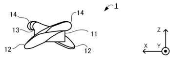
プロペラ1は、図1Aに示すように、回転することのできる中心部であるハブ11と、ハブ11から互いに外側に延びる一対の羽根を含む翼部12と、ハブ11と翼部12とを屈曲可能に接続する屈曲部13と、翼部12の縁に設けられた変形可能エッジ14と、屈曲部13に埋設され、ハブ11と翼部12とを接続する繊維状の複数の腱15と、を備える。
The
以下、図1Aに示した、翼部12の延びる方向を+Y方向、揚力を生ずる方向を+Z方向、Y方向及びZ方向に垂直な方向を+X方向として説明する。
Hereinafter, the direction in which the
図1A、図1Bに示すように、ハブ11は、プロペラ1の中心に配置されている。ハブ11は、プロペラ1の回転軸をプロペラ1の他の部材と結合する中心部である。ハブ11の中央において、図示しないモータMの回転軸との接続のための孔HがZ方向にねじ切りされている。ハブ11は、円環Rとその円環Rから連続的に滑らかに径方向外側に向けて突出するように形成された移行部Tとを含む。移行部Tの一端において、ハブ11は屈曲部13と接続されている。ハブ11は、剛性の高い硬質プラスチックの素材、例えば、ABS樹脂、PLA(ポリ乳酸、polylactic acid)樹脂を含む。
As shown in FIGS. 1A and 1B,
翼部12は、ハブ11と同様に、剛性の高い硬質プラスチックの素材を含む。
翼部12は、後述する変形可能エッジ14と一体としてプロペラ1の回転翼(ブレード)として機能する形状に形成されている。
なお、プロペラ1の具体的な形状は、理論的に又はシミュレーションにより計算されてもよく、図1Aから図1Dに示した形状に限定されるものではない。
The
The specific shape of
屈曲部13は、ハブ11及び翼部12に比べて可撓性の高い素材、例えば、シリコーンゴムを含む。また、屈曲部13の剛性は、ハブ11及び翼部12の剛性よりも低い。屈曲部13は、ハブ11と翼部12との間に配置されており、ハブ11の外側に位置する移行部Tと翼部12の内側とを滑らかに接続する連続的に変化する形状に形成されている。屈曲部13が撓むことで、翼部12は、上下方向及び回転方向に変位することができる。
The
図1B、図1Cに示すように、変形可能エッジ14は、翼部12の回転方向Dの縁に設けられている前縁部である。回転方向Dは、プロペラ1においては反時計回りである。
変形可能エッジ14は、屈曲部13と同様に、ハブ11及び翼部12に比べて可撓性の高い素材、例えば、シリコーンゴムを含む。変形可能エッジ14の剛性は、ハブ11及び翼部12の剛性よりも低い。
なお、翼部12は、請求項における後翼部の一例であり、変形可能エッジ14は、請求項における前縁部の一例である。As shown in FIGS. 1B and 1C, the
The
The
腱15は、柔軟かつ強度の高い繊維素材、例えば、ナイロン繊維を含む糸状の部材である。腱15は、図1A~図1Cにおいて破線で示したように、ハブ11と翼部12との間に複数張られており、それらの周囲が屈曲部13に覆われている。腱15の剛性は、屈曲部13の剛性よりも低く、腱15の可撓性は、屈曲部13の可撓性よりも高い。
The
このように、プロペラ1においては、ハブ11及び翼部12の可撓性が低い一方で、屈曲部13の可撓性が高く、強度の高い腱15が翼部12をハブ11と接続している。このため、プロペラ1が外力を受けると、翼部12及び変形可能エッジ14はその外力によって変位するが、その外力がなくなると、速やかにもとの位置に復帰する。また、プロペラ1は、部分的に可撓性を有する素材を含むにとどまるので、可撓性を有する素材で全体が構成される場合に比べ、回転に伴う捻れや振動が低減される。
Thus, in the
次に、図2を参照して、プロペラ1の製造方法を説明する。
まず、プロペラ1の形状を設計する(ステップS1)。具体的には、例えば、数値計算ソフトウェア、シミュレータ、CAD(Computer Aided Design)ソフトウェア等を用いて、プロペラ1の各部品、すなわち、ハブ11、翼部12、屈曲部13、変形可能エッジ14等の形状を設計する。Next, a method for manufacturing the
First, the shape of the
ステップS1で生成された設計データと3Dプリンタを用いて、硬い部品、すなわち、ハブ11及び翼部12の3Dプリントを行う(ステップS2)。
なお、3Dプリンタを用いず、後述する成形のステップにおける方法と同様に、型を用いた成形を行うことで硬い部品を形成してもよい。The design data generated in step S1 and the 3D printer are used to 3D print the hard parts, ie, the
It should be noted that a hard part may be formed by molding using a mold, similar to the method in the molding step described below, without using a 3D printer.
硬い部品と腱15を接着して、プロペラ1の骨格であるフレームを形成する(ステップS3)。具体的には、ハブ11と翼部12の互いに向かい合う面には小孔が形成されているので、これらの小孔に接着剤を塗布した腱15を差し込んで固定する。なお、接着には、硬い部品と腱15の両方に適した接着剤を用いる。
A frame, which is the skeleton of the
型に、ステップS3で形成されたフレームを載せて位置決めする(ステップS4)。このステップで用いられる型は、設計のステップで生成されたハブ11、翼部12、屈曲部13及び変形可能エッジ14の占める空間のデータから、予め3Dプリント等の方法で形成される。
The frame formed in step S3 is placed on the mold and positioned (step S4). The mold used in this step is formed in advance by a method such as 3D printing from data of the space occupied by the
成形を行う(ステップS5)。例えば、主材と硬化剤を混合したものを型に流し込み、固まるまで静かに保持する。 Molding is performed (step S5). For example, a mixture of the main material and hardener is poured into a mold and gently held until it hardens.
成形物を型から分離する(ステップS6)。このステップで、成形物から余分な部分、所謂バリを取り除いておく。 The molding is separated from the mold (step S6). In this step, excess parts, so-called burrs, are removed from the molding.
ハブ11、翼部12、屈曲部13及び変形可能エッジ14の相互に接する部分に接着剤を塗布して接着する微調整を行う(ステップS7)。これにより、プロペラ1の硬い部品と軟らかい部品とがより強固に接続される。
以上の工程を経て、プロペラ1が完成する。Adhesive is applied to the portions of the
Through the above steps, the
これまで述べてきた構成及び製造方法によって製造されたプロペラ1の特性を調べる実験について説明する。
An experiment for investigating the characteristics of the
(第1の実験)
プロペラ1の回転速度を変化させた場合にプロペラ1によって生成される揚力を測定する実験を行った。
プロペラ1によって生成される揚力を正確に測定するため、デジタルフォースゲージを用いて、プロペラ1の揚力を引張力として計測した。
また、図3Aに示すように、プロペラ1と同一の形状を有し、硬い素材のみでできている従来のプロペラ101を比較例として用いた。(First experiment)
An experiment was conducted to measure the lift generated by the
In order to accurately measure the lift generated by
Also, as shown in FIG. 3A, a
以下のプロペラを回転させる実験では、モータMの回転軸にプロペラを接続し、モータMに供給する電流を変化させることでモータMの回転数を任意に設定できるようにした。以下の実験では、プロペラはモータMに直接接続されているから、プロペラの回転速度は、モータMの回転速度と等しい。 In the experiment to rotate the propeller described below, the propeller was connected to the rotating shaft of the motor M, and the rotation speed of the motor M was arbitrarily set by changing the current supplied to the motor M. In the following experiments, the propeller's rotational speed is equal to the motor's rotational speed, since the propeller is directly connected to the motor.
図3Bに、モータMの回転速度(rpm)に対する揚力(N)の関係を示す。
図3Bに示すように、回転速度を大きくすると、プロペラ1によって生成される揚力は、従来のプロペラ101によって生成される揚力と同様に、直線的に大きくなるという結果が得られた。
また、同じ回転速度で比較すると、プロペラ1を用いて得られる揚力は、従来のプロペラ101を用いて得られる揚力に対して、約22.6%小さい。しかし、回転速度を上げることで、プロペラ1でも従来のプロペラ101と同程度の揚力が得られるという結果が得られた。FIG. 3B shows the relationship between the rotational speed (rpm) of the motor M and the lift force (N).
As shown in FIG. 3B, increasing the rotational speed resulted in a linear increase in the lift generated by the
Also, when compared at the same rotational speed, the lift obtained using the
この実験から、以下のことが理解される。
柔軟なプロペラ1によって生成される揚力は、同一の形状を有する従来のプロペラ101によって生成される揚力より小さい。しかし、回転速度を上げることで、柔軟なプロペラ1は、従来のプロペラ101と同程度の揚力を生成することができる。このため、従来のプロペラ101を柔軟なプロペラ1に置き換えてもドローンの飛行に支障は生じないと考えられる。From this experiment, the following can be understood.
The lift generated by
(第2の実験)
回転翼を障害物に接触させた場合における障害物の損傷の有無、及びプロペラ1と従来のプロペラ101の損傷の程度をそれぞれ調べる実験を行った。
障害物として、幅3mm、厚さ0.2mmのポリプロピレン製のリボンを用いた。このリボンをZ方向に張り、リボンの中央付近にプロペラ1又はプロペラ101の先端が衝突するように、プロペラ1又はプロペラ101を配置した。また、プロペラ1の回転速度を3200rpm、プロペラ101の回転速度を2800rpmに設定した。これらの回転速度は、プロペラ1、101の最高速度であり、第1の実験の結果から理解されるように、いずれも約1.3Nの揚力を生じる条件として設定されたものである。(Second experiment)
An experiment was conducted to examine whether or not the obstacle was damaged when the rotor blades were brought into contact with the obstacle, and to examine the degree of damage to the
A polypropylene ribbon having a width of 3 mm and a thickness of 0.2 mm was used as an obstacle. This ribbon was stretched in the Z direction, and
図4A~4D、図5A~5Dは、それぞれ、プロペラ1とプロペラ101がリボンに接触する瞬間の前後に撮影されたハイスピードカメラの画像である。図4A~4D、図5A~5Dは、いずれも、時間が経過した順に並べられている。
4A-4D and 5A-5D are high speed camera images taken before and after the
図4A、図5Aの時点では、プロペラ1及びプロペラ101は、どちらもまだリボンと接触していない。
図4B、図5Bの時点で、プロペラ1及びプロペラ101は、それぞれリボンと接触した。
図4C、図5Cの時点で、プロペラ1の翼部12は撓んでいるものの、リボンの形状は変化していない。また、この時点で、プロペラ101の回転翼は撓んでいないが、リボンの形状は折れ曲がるように変化している。
図4D、図5Dから、プロペラ1の翼部12は撓んでおらず、リボンの形状も変化していないこと、プロペラ101の回転翼は撓んでいないが、リボンは完全に破断したことが理解される。At the time of Figures 4A and 5A, neither
At the time of Figures 4B and 5B,
At the time of FIGS. 4C and 5C, the
From FIGS. 4D and 5D, it can be understood that the
この実験から、同じ揚力を生じる高い回転速度において、プロペラ1が障害物に接触してもプロペラ1自身及び接触した対象に損傷は生じないが、プロペラ101は接触した対象に損傷を与える場合があることが理解される。
From this experiment, it can be seen that at high rotational speeds that produce the same lift force,
(第3の実験)
障害物にプロペラ1を接触させた場合におけるプロペラ1の変形を調べる実験を行った。
障害物として、ナイロン繊維のコアを埋め込んだ人の指の模型を用いた。また、プロペラ1の回転速度を3200rpmに設定した。(Third experiment)
An experiment was conducted to examine the deformation of the
A model of a human finger with a core of nylon fiber embedded was used as an obstacle. Also, the rotational speed of the
図6A~6Eは、それぞれ、プロペラ1が障害物に接触した後に撮影されたハイスピードカメラの画像である。図6A~6Eは、時間が経過した順に並べられている。
6A-6E are high-speed camera images taken after
図6A及び図6Bに示した画像は、それぞれ、プロペラ1の翼部12の一方が障害物と接触した直後の画像、もう片方が障害物と接触した直後の画像である。これらの画像から、翼部12が障害物と接触すると、プロペラ1は、屈曲部13において大きく曲がることが理解される。
図6Cに示した画像は、プロペラ1を回転させたまま障害物を上方に引き抜く途中の画像である。この画像から、翼部12が障害物を避けるように下方に捻れることが理解される。
図6D及び図6Eに示した画像は、障害物を取り去った直後の画像である。これらの画像から、障害物を取り去ると、翼部12及び屈曲部13の形状が復帰することが理解される。
なお、図6Aに示した画像が撮影されてから図6Eに示した画像が撮影されるまでに経過した時間は約0.4秒であるため、プロペラ1が障害物と衝突して変形してから元の形状に復帰するまでに要する時間も約0.4秒である。The images shown in FIGS. 6A and 6B are images immediately after one of the
The image shown in FIG. 6C is an image in the middle of pulling up the obstacle while rotating the
The images shown in FIGS. 6D and 6E are images immediately after removing the obstacle. From these images, it can be seen that the shape of the
It should be noted that since the time elapsed from the image shown in FIG. 6A to the image shown in FIG. It takes about 0.4 second to return to the original shape.
この実験から、人の手の指と接触した場合において、プロペラ1によれば、屈曲部13が折れ曲がり、捻れ、もとに戻ることで、1秒に満たない比較的短時間の間に障害物との接触による衝撃力が吸収されることが理解される。
From this experiment, when the
(第4の実験)
屈曲部13の形状を変えて、プロペラ1が障害物と衝突した後に元の形状に復帰するまでの時間と、プロペラ1が生成する揚力の大きさを調べる実験を行った。
図7A、図7B、図7Cにそれぞれ示すように、比較例に係るプロペラ201、301、401は、屈曲部13と同一の外形形状を備える。
プロペラ201~401の屈曲部213~413は、腱15を6本ずつ備える。屈曲部213~413の直径は、いずれも0.62mmである。屈曲部213~413の長さは互いに異なっており、屈曲部213の長さはL1=6mm、屈曲部313の長さはL2=12mm、屈曲部413の長さは、L3=18mmである。(Fourth experiment)
Experiments were conducted by changing the shape of the
As shown in FIGS. 7A, 7B, and 7C,
The bent portions 213-413 of the propellers 201-401 have six
なお、図1Aに示したプロペラ1の屈曲部13の長さは、L2=12mmである。
屈曲部213~413は、屈曲部13と同様に可撓性を有する材料を含むが、屈曲部13に比べて硬い材料を用いて造形されている。In addition, the length of the
The
図8A、図8B、図8Cに、人の指を模した樹脂製の角柱にプロペラ301、401、201をそれぞれ衝突させた直後の形状の変化を示す。例えば、「Frame n」は、衝突した瞬間における画像を表し、「Frame n+1」は、衝突した瞬間から1フレーム分の時間を経過した後の画像を表す。隣接するフレーム間の時間的な間隔は等しく、約1ミリ秒である。
理解を容易にするため、図8A~8Cには、代表的なフレームのみを示した。FIGS. 8A, 8B, and 8C show changes in shape immediately after the
For ease of understanding, only representative frames are shown in FIGS. 8A-8C.
図8Aに示したように、屈曲部313の長さがL2=12mmである場合には、Frame n+234に相当する時間、すなわち、衝突から0.244秒を経過すると、プロペラ301は元の形状に復帰した。
これに対し、図8Bに示したように、屈曲部413の長さがL3=18mmである場合には、プロペラ401は、元の形状に復帰するまでに、Frame n+328に相当する時間、すなわち、衝突から0.342秒の時間を要した。
また、図8Cに示したように、屈曲部213の長さがL1=6mmである場合には、衝突により、プロペラ201は、不可逆的な損傷を受けたため、元の形状に復帰しなかった。As shown in FIG. 8A, when the length of the
On the other hand, as shown in FIG. 8B, when the length of the
Also, as shown in FIG. 8C, when the length of the
この結果から、屈曲部213~413を短くすれば、障害物と衝突した後に元の形状に復帰するまでの時間を短縮することができること、及び屈曲部213~413を短くし過ぎると、障害物に対して脆弱になることが理解される。特に、長さL2=12mmの屈曲部313を備えるプロペラ301は、障害物から受ける衝撃力を素早く吸収することができることが理解される。
From these results, it was found that shortening the
図8Dは、プロペラ201~401が生成する揚力を、モータMの回転速度を変えて計測したものである。
ほとんど全てのモータMの回転数において、プロペラ201、301、401の順に大きい揚力を生じた。FIG. 8D shows lift forces generated by the
At almost all rotation speeds of the motor M, the
この結果から、屈曲部213~413が短いほど、又はモータの回転速度が高いほど、プロペラ201~401は大きな揚力を生じることが理解される。 From these results, it can be understood that the shorter the bent portions 213-413 or the higher the rotational speed of the motor, the greater the lift force produced by the propellers 201-401.
揚力の大きさと障害物に対する耐性を両立する観点から、プロペラ1の屈曲部13の長さをL2=12mm以上とすることが望ましいことが理解される。
It is understood that the length of the
(第5の実験)
変形可能エッジ14を備えないプロペラについて、屈曲部13の長さを変えた場合に発生する揚力を調べるシミュレーション実験を行った。(Fifth experiment)
For a propeller without
図9A、図9B、図9Cに示すように、比較例に係るプロペラ501、601、701の屈曲部513~713の長さは、それぞれ、L1=6mm、L2=12mm、L3=18mmである。
プロペラ201~401と比較して、プロペラ501~701は、変形可能エッジ14を備えない点において異なる。As shown in FIGS. 9A, 9B, and 9C, the lengths of
Compared to propellers 201-401, propellers 501-701 differ in that they do not have
図9Dに示すように、モータMの回転速度が2000rpmから3500rpmという比較的高い範囲では、揚力の大きさは、屈曲部513~713の長さL1~L3にほとんど依存しないというシミュレーション結果が得られた。
As shown in FIG. 9D, the simulation results show that the magnitude of the lift force hardly depends on the lengths L1 to L3 of the bending
この結果は、モータMの回転速度が高い場合には、プロペラ501~701に働く遠心力が大きくなり、屈曲部513~713の形状に関わらず、腱15に支えられてプロペラ501~701全体の形状が安定するためであると考えられる。
As a result, when the rotational speed of the motor M is high, the centrifugal force acting on the
なお、図8Dと図9Dから、屈曲部の長さL1、L2、L3が等しいもの同士で比較すると、ほとんど全てのモータMの回転数において、プロペラ501~701は、プロペラ201~401に比べて大きな揚力を発生させることも理解される。
8D and 9D, when the lengths L1, L2, and L3 of the bent portions are compared with each other, the
(第6の実験)
プロペラ1が腱15を備える場合と備えない場合とを比較する実験を行った。
図10Aに示すように、比較例に係るプロペラ801の屈曲部813は、腱を備えない。
屈曲部813は、ハブ11及び翼部12と重なり合って配置され、屈曲部813とハブ11、屈曲部813と翼部12がそれぞれ接合されている。
S部拡大図に示すように、屈曲部813のうち、ハブ11と重なり合った部分、翼部12と重なり合った部分のそれぞれに、ピン816が矢印で示す方向に打ち込まれている。(Sixth experiment)
An experiment was conducted to compare the
As shown in FIG. 10A, the bending
The
As shown in the enlarged view of the S section, a
図7Bに示したように、比較例に係るプロペラ301は、プロペラ801と同等の形状に形成されている。プロペラ301は、屈曲部313に、屈曲部13と同様に腱15を備える。
As shown in FIG. 7B ,
図10Bに示すように、プロペラ301の翼部12の先端は、回転軸に平行に配置された定規の目盛りで、43.5mmを指している。
図10Cに示すように、プロペラ801の翼部12の先端は、回転軸に平行に配置された定規の目盛りで、35.5mmを指している。As shown in FIG. 10B, the tip of
As shown in FIG. 10C, the tip of
プロペラ301、801を回転させない静止状態において、プロペラ801においては、プロペラ301に比べ、翼部12の先端が8.0mm下がっている。
In a stationary state in which the
これは、プロペラ801は、腱15を備えないことにより、翼部12の自重の影響をより大きく受けるためであると考えられる。
このため、腱15は、プロペラ1の剛性を向上させることに寄与していることが理解される。It is believed that this is because the
Therefore, it is understood that the
図11A、図11Bは、静止状態において、プロペラ801、301の翼部12の先端部が同一の位置に達するまで変形させるために必要な力の大きさを計測したものである。
FIGS. 11A and 11B show measurements of the magnitude of the force required to deform the tips of the
図11Aに示すように、プロペラ301の翼部12の先端は、回転軸に平行に配置された定規の目盛りで、67.0mmを指していた。プロペラ301の翼部12の先端を基準位置まで23.0mm押し下げるために必要な力の大きさは0.120Nであった。
図11Bに示すように、プロペラ801の翼部12の先端は、回転軸に平行に配置された定規の目盛りで、58.5mmを指していた。プロペラ801の翼部12の先端を基準位置まで16.5mm押し下げるために必要な力の大きさは0.039Nであった。As shown in FIG. 11A, the tip of
As shown in FIG. 11B, the tip of
この実験から、腱15を備えるプロペラ301を基準位置まで変形させるために必要な力の大きさは、腱を備えないプロペラ801を同じ基準位置まで変形させるために必要な力の大きさの約3倍であることが理解される。
このため、腱15は、プロペラ1の剛性を向上させることに寄与していることが理解される。また、屈曲部13の材料、腱15の材料及び直径、腱15の数等が、プロペラ1の剛性に影響を与えることが推測される。From this experiment, the amount of force required to deform
Therefore, it is understood that the
次に、図11Cに示すように、回転状態において、プロペラ801は、プロペラ301に比べて小さい揚力を生成するという結果が得られた。
また、モータMの回転速度が大きくなるにつれて、プロペラ801とプロペラ301が生成する揚力の大きさの差が大きくなるという結果が得られた。
さらに、2000rpmを超えるモータMの回転速度では、腱15を備えないプロペラ801の屈曲部813が損傷するため、測定自体を行うことができなかった。
これらの結果が得られたのは、腱15を備えないプロペラ801は、腱15を備えるプロペラ301に比べて、モータMの回転速度が大きくなるにつれて遠心力の影響を強く受けるためであると考えられる。
このため、腱15は、高い回転速度において、プロペラ1全体の形状を維持し、プロペラ1の揚力を向上させることに寄与していることが理解される。Next, as shown in FIG. 11C, the result was that
Also, the result was obtained that as the rotation speed of the motor M increases, the difference in the magnitude of the lift generated by the
Furthermore, at rotational speeds of the motor M exceeding 2000 rpm, the
These results are obtained because the
Therefore, it is understood that the
図11D、図11Eは、プロペラ801、301が発生させる揚力の大きさをシミュレーションと比較したものである。
シミュレーションでは、モータMの回転速度が大きくなれば、揚力も大きくなることが予想された。実験結果は、ほぼシミュレーションに沿うものであり、モータMの回転速度が大きくなれば、プロペラ801、301によって生成される揚力も大きくなった。11D and 11E compare the magnitude of lift generated by the
In the simulation, it was expected that as the rotation speed of the motor M increased, the lift force also increased. The experimental results are generally in line with the simulation, and the lift generated by the
この実験から、プロペラ1によって生成される揚力の大きさは、シミュレーションによって予測された期待通りのものであることが示された。
This experiment showed that the amount of lift generated by
(第7の実験)
ドローンを飛行させ、プロペラ1と従来のプロペラ101を障害物に接触させた場合における衝撃力の違いを調べる実験を行った。(Seventh experiment)
An experiment was conducted to examine the difference in impact force when the drone was flown and the
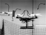
図12A、図12Bに示すように、力センサFSの先端には硬い障害物ROが接続され、ドローンDRにはプロペラ1、101が取り付けられている。プロペラ1、101を回転させてドローンDRを飛行させながら障害物ROの衝突領域CAに衝突させ、プロペラ1、101によって障害物に加えられた衝撃力を、力センサFSを介して読み取った。
As shown in FIGS. 12A and 12B, a hard obstacle RO is connected to the tip of the force sensor FS, and
図12Cに示すように、プロペラ1、101のいずれも、衝突した瞬間から約3ms経過後に最大の衝撃力を硬い障害物ROに与えた。プロペラ1が硬い障害物ROに与えた最大の衝撃力は約10Nであり、プロペラ101が硬い障害物ROに与えた最大の衝撃力は約67Nであった。
また、ほぼ全ての時間において、プロペラ1が硬い障害物ROに与えた衝撃力の大きさは、プロペラ101が硬い障害物ROに与えた衝撃力の大きさを超えなかった。As shown in FIG. 12C, both the
Also, at almost all times, the magnitude of the impact force applied by
この実験から、プロペラ1によれば、実際に飛行するドローンが障害物と衝突しても、従来のプロペラ101と比べて衝撃力を与えにくいことが理解される。
From this experiment, it is understood that the
(第2の実施の形態)
プロペラ1は、2つの羽根を有するものとして説明されたが、羽根の数はこれに限られない。
本発明の第2の実施の形態に係るプロペラ21は、図13に示すように、2対で合計4枚の羽根を有する。これらの4枚の羽根のそれぞれの形状は、プロペラ1の羽根、すなわち、翼部12、屈曲部13及び変形可能エッジ14と同一である。4枚の羽根は、プロペラ1と異なり、回転軸を中心として90°ごとに配置されている。
プロペラ21によれば、羽根の面積がより大きいため、2枚羽根のプロペラ1に比べて飛行時の振動を低減することができる。(Second embodiment)
Although
As shown in FIG. 13, the
Since the
本発明は、本発明の広義の精神と範囲を逸脱することなく、様々な実施の形態及び変形が可能とされるものである。また、上述した実施の形態は、この発明を説明するためのものであり、本発明の範囲を限定するものではない。すなわち、本発明の範囲は、実施の形態ではなく、特許請求の範囲によって示される。そして、特許請求の範囲内及びそれと同等の発明の意義の範囲内で施される様々な変形が、この発明の範囲内とみなされる。 The present invention is capable of various embodiments and modifications without departing from the broader spirit and scope of the invention. Moreover, the embodiment described above is for explaining the present invention, and does not limit the scope of the present invention. That is, the scope of the present invention is indicated by the claims rather than the embodiments. Various modifications made within the scope of the claims and within the meaning of equivalent inventions are considered to be within the scope of the present invention.
本出願は、2019年10月31日に出願された日本国特許出願特願2019-198143号に基づく。本明細書中に、日本国特許出願特願2019-198143号の明細書、特許請求の範囲、及び図面全体を参照として取り込むものとする。 This application is based on Japanese Patent Application No. 2019-198143 filed on October 31, 2019. The entire specification, claims, and drawings of Japanese Patent Application No. 2019-198143 are incorporated herein by reference.
1、21、101、201、301、401、501、601、701、801 プロペラ
11 ハブ
12 翼部
13、213、313、413、513、613、713、813 屈曲部
14 変形可能エッジ
15 腱
816 ピン
M モータ
D 回転方向
H 孔
R 円環
T 移行部
CA 衝突領域
DR ドローン
FS 力センサ
RO 硬い障害物1, 21, 101, 201, 301, 401, 501, 601, 701, 801
Claims (1)
前記中心部から連続的に滑らかに径方向外側に向けて突出するように形成された移行部と、
前記移行部と連続的に滑らかに接続された可撓性を有する部材を含む屈曲部と、
前記屈曲部と接続され、当該屈曲部から連続的に滑らかに前記径方向外側に延びるように形成されている羽根と、
前記屈曲部の内部に配置され、前記移行部と前記羽根との間に張られた繊維と、
前記羽根の回転方向の前側に位置する前縁部と、を備え、
前記中心部、前記移行部及び前記羽根の可撓性が前記屈曲部の可撓性よりも低い、
プロペラ。 the center and
a transition portion formed to protrude radially outward continuously and smoothly from the central portion;
a bending section including a flexible member continuously and smoothly connected to the transition section;
a blade connected to the bent portion and formed to extend continuously and smoothly outward in the radial direction from the bent portion;
fibers disposed within the bend and stretched between the transition and the vane;
a front edge located on the front side in the rotational direction of the blade ,
the flexibility of the central portion, the transition portion and the vanes is less than the flexibility of the bending portion ;
propeller.
Applications Claiming Priority (3)
| Application Number | Priority Date | Filing Date | Title |
|---|---|---|---|
| JP2019198143 | 2019-10-31 | ||
| JP2019198143 | 2019-10-31 | ||
| PCT/JP2020/040775 WO2021085588A1 (en) | 2019-10-31 | 2020-10-30 | Propeller |
Publications (3)
| Publication Number | Publication Date |
|---|---|
| JPWO2021085588A1 JPWO2021085588A1 (en) | 2021-05-06 |
| JPWO2021085588A5 JPWO2021085588A5 (en) | 2022-07-28 |
| JP7236171B2 true JP7236171B2 (en) | 2023-03-09 |
Family
ID=75715198
Family Applications (1)
| Application Number | Title | Priority Date | Filing Date |
|---|---|---|---|
| JP2021553714A Active JP7236171B2 (en) | 2019-10-31 | 2020-10-30 | propeller |
Country Status (2)
| Country | Link |
|---|---|
| JP (1) | JP7236171B2 (en) |
| WO (1) | WO2021085588A1 (en) |
Citations (4)
| Publication number | Priority date | Publication date | Assignee | Title |
|---|---|---|---|---|
| US4627791A (en) | 1982-11-10 | 1986-12-09 | Marshall Andrew C | Aeroelastically responsive composite propeller |
| US20160347441A1 (en) | 2015-06-01 | 2016-12-01 | Northrop Grumman Systems Corporation | Deployable propeller |
| US20180043988A1 (en) | 2016-08-09 | 2018-02-15 | Gopro, Inc. | Automated Variable Pitch Propeller Blade |
| JP2019104369A (en) | 2017-12-12 | 2019-06-27 | ホッティーポリマー株式会社 | Rotary impeller and manufacturing method of the same |
Family Cites Families (4)
| Publication number | Priority date | Publication date | Assignee | Title |
|---|---|---|---|---|
| FR2041747A1 (en) * | 1969-05-20 | 1971-02-05 | Sud Aviation | |
| US5108262A (en) * | 1990-03-23 | 1992-04-28 | The United States Of America As Represented By The Secretary Of The Navy | High damping flexible propeller/impleller |
| US20030145541A1 (en) * | 2002-02-01 | 2003-08-07 | Brightwell Lionel L. | Scaffold plank end cap |
| US20190135419A1 (en) * | 2017-11-03 | 2019-05-09 | Vantage Robotics Llc | Foldable unmaned aerial vehicle (uav) |
-
2020
- 2020-10-30 WO PCT/JP2020/040775 patent/WO2021085588A1/en active Application Filing
- 2020-10-30 JP JP2021553714A patent/JP7236171B2/en active Active
Patent Citations (4)
| Publication number | Priority date | Publication date | Assignee | Title |
|---|---|---|---|---|
| US4627791A (en) | 1982-11-10 | 1986-12-09 | Marshall Andrew C | Aeroelastically responsive composite propeller |
| US20160347441A1 (en) | 2015-06-01 | 2016-12-01 | Northrop Grumman Systems Corporation | Deployable propeller |
| US20180043988A1 (en) | 2016-08-09 | 2018-02-15 | Gopro, Inc. | Automated Variable Pitch Propeller Blade |
| JP2019104369A (en) | 2017-12-12 | 2019-06-27 | ホッティーポリマー株式会社 | Rotary impeller and manufacturing method of the same |
Also Published As
| Publication number | Publication date |
|---|---|
| WO2021085588A1 (en) | 2021-05-06 |
| JPWO2021085588A1 (en) | 2021-05-06 |
Similar Documents
| Publication | Publication Date | Title |
|---|---|---|
| Guo et al. | Theoretical and experimental study of a piezoelectric flapping wing rotor for micro aerial vehicle | |
| US20100012770A1 (en) | System and Method for Improved Rotor Tip Performance | |
| Bruggeman | Improving flight performance of DelFly II in hover by improving wing design and driving mechanism | |
| US10315757B2 (en) | Propeller blade beta twist | |
| JP5710005B2 (en) | Slat, aircraft wing, aircraft rotor blade, aircraft | |
| JP7236171B2 (en) | propeller | |
| JP2002168728A (en) | Model for flutter test | |
| EP3293110A1 (en) | Core material for balanced rotor blade | |
| JP2006162663A (en) | Microrocking element | |
| US11396368B2 (en) | Airplane wing | |
| Bui et al. | Tombo propeller: bioinspired deformable structure toward collision-accommodated control for drones | |
| CN207917131U (en) | Propeller, Power Component and aircraft | |
| KR20130013466A (en) | Flight performance analyzing system and the method for helicopter | |
| CN115906295B (en) | Unmanned aerial vehicle health monitoring method and device based on digital twinning | |
| JP2004010020A (en) | Trailing edge configuration of laminar airfoil | |
| JP3644497B2 (en) | Rotor blade of rotorcraft | |
| JP6989845B2 (en) | Rotor | |
| JPH0727665A (en) | Model for testing aeroelasticity | |
| Bernhard et al. | Hover testing of active rotor blade-tips using a piezo-induced bending-torsion coupled beam | |
| CN207106882U (en) | Blade, propeller, Power Component and unmanned vehicle | |
| JP4134132B2 (en) | Blade airfoil design method | |
| CN207917132U (en) | Propeller, Power Component and aircraft | |
| JP2002168727A (en) | Model for flutter test | |
| JP4537439B2 (en) | Micro oscillating device | |
| Ventura Diaz et al. | A physics-based approach to urban air mobility |
Legal Events
| Date | Code | Title | Description |
|---|---|---|---|
| A529 | Written submission of copy of amendment under article 34 pct |
Free format text: JAPANESE INTERMEDIATE CODE: A5211 Effective date: 20220407 |
|
| A621 | Written request for application examination |
Free format text: JAPANESE INTERMEDIATE CODE: A621 Effective date: 20220407 |
|
| A521 | Request for written amendment filed |
Free format text: JAPANESE INTERMEDIATE CODE: A821 Effective date: 20220407 |
|
| A131 | Notification of reasons for refusal |
Free format text: JAPANESE INTERMEDIATE CODE: A131 Effective date: 20221122 |
|
| A521 | Request for written amendment filed |
Free format text: JAPANESE INTERMEDIATE CODE: A523 Effective date: 20230119 |
|
| TRDD | Decision of grant or rejection written | ||
| A01 | Written decision to grant a patent or to grant a registration (utility model) |
Free format text: JAPANESE INTERMEDIATE CODE: A01 Effective date: 20230131 |
|
| A61 | First payment of annual fees (during grant procedure) |
Free format text: JAPANESE INTERMEDIATE CODE: A61 Effective date: 20230217 |
|
| R150 | Certificate of patent or registration of utility model |
Ref document number: 7236171 Country of ref document: JP Free format text: JAPANESE INTERMEDIATE CODE: R150 |