JP7226930B2 - Calibration device and electronic mirror system - Google Patents
Calibration device and electronic mirror system Download PDFInfo
- Publication number
- JP7226930B2 JP7226930B2 JP2018109139A JP2018109139A JP7226930B2 JP 7226930 B2 JP7226930 B2 JP 7226930B2 JP 2018109139 A JP2018109139 A JP 2018109139A JP 2018109139 A JP2018109139 A JP 2018109139A JP 7226930 B2 JP7226930 B2 JP 7226930B2
- Authority
- JP
- Japan
- Prior art keywords
- vehicle
- road
- image
- lane
- traveling
- Prior art date
- Legal status (The legal status is an assumption and is not a legal conclusion. Google has not performed a legal analysis and makes no representation as to the accuracy of the status listed.)
- Active
Links
- 238000001514 detection method Methods 0.000 claims description 32
- 238000010586 diagram Methods 0.000 description 11
- 238000006073 displacement reaction Methods 0.000 description 6
- 238000013459 approach Methods 0.000 description 3
- 238000004904 shortening Methods 0.000 description 1
- 230000001629 suppression Effects 0.000 description 1
- 230000007704 transition Effects 0.000 description 1
Images


Classifications
-
- B—PERFORMING OPERATIONS; TRANSPORTING
- B60—VEHICLES IN GENERAL
- B60R—VEHICLES, VEHICLE FITTINGS, OR VEHICLE PARTS, NOT OTHERWISE PROVIDED FOR
- B60R11/00—Arrangements for holding or mounting articles, not otherwise provided for
- B60R11/02—Arrangements for holding or mounting articles, not otherwise provided for for radio sets, television sets, telephones, or the like; Arrangement of controls thereof
-
- G—PHYSICS
- G06—COMPUTING; CALCULATING OR COUNTING
- G06T—IMAGE DATA PROCESSING OR GENERATION, IN GENERAL
- G06T7/00—Image analysis
-
- G—PHYSICS
- G08—SIGNALLING
- G08G—TRAFFIC CONTROL SYSTEMS
- G08G1/00—Traffic control systems for road vehicles
- G08G1/16—Anti-collision systems
-
- G—PHYSICS
- G09—EDUCATION; CRYPTOGRAPHY; DISPLAY; ADVERTISING; SEALS
- G09G—ARRANGEMENTS OR CIRCUITS FOR CONTROL OF INDICATING DEVICES USING STATIC MEANS TO PRESENT VARIABLE INFORMATION
- G09G5/00—Control arrangements or circuits for visual indicators common to cathode-ray tube indicators and other visual indicators
- G09G5/08—Cursor circuits
-
- G—PHYSICS
- G09—EDUCATION; CRYPTOGRAPHY; DISPLAY; ADVERTISING; SEALS
- G09G—ARRANGEMENTS OR CIRCUITS FOR CONTROL OF INDICATING DEVICES USING STATIC MEANS TO PRESENT VARIABLE INFORMATION
- G09G5/00—Control arrangements or circuits for visual indicators common to cathode-ray tube indicators and other visual indicators
- G09G5/36—Control arrangements or circuits for visual indicators common to cathode-ray tube indicators and other visual indicators characterised by the display of a graphic pattern, e.g. using an all-points-addressable [APA] memory
-
- H—ELECTRICITY
- H04—ELECTRIC COMMUNICATION TECHNIQUE
- H04N—PICTORIAL COMMUNICATION, e.g. TELEVISION
- H04N7/00—Television systems
- H04N7/18—Closed-circuit television [CCTV] systems, i.e. systems in which the video signal is not broadcast
Landscapes
- Engineering & Computer Science (AREA)
- Physics & Mathematics (AREA)
- General Physics & Mathematics (AREA)
- Theoretical Computer Science (AREA)
- Computer Hardware Design (AREA)
- Multimedia (AREA)
- Mechanical Engineering (AREA)
- Signal Processing (AREA)
- Computer Vision & Pattern Recognition (AREA)
- Traffic Control Systems (AREA)
- Fittings On The Vehicle Exterior For Carrying Loads, And Devices For Holding Or Mounting Articles (AREA)
- Closed-Circuit Television Systems (AREA)
- Controls And Circuits For Display Device (AREA)
- Image Analysis (AREA)
- Image Processing (AREA)
Description
本発明は、キャリブレーション装置及び電子ミラーシステムに関する。 The present invention relates to a calibration device and an electronic mirror system.
車両の運転者は、車線変更等の際に、車両の両側部に後方を向いて設けられたサイドミラーを見て、そのサイドミラーで反射した後方領域の像を目視で確認している。 2. Description of the Related Art When changing lanes or the like, a driver of a vehicle looks at side mirrors provided on both sides of the vehicle to face rearward, and visually confirms the image of the rear region reflected by the side mirrors.
近年、サイドミラーに代えて、後方を向いたカメラと、そのカメラで撮像された後方領域の画像を表示する、車室内に設置されたモニタと、を有するいわゆる電子ミラーシステムが開発されている(例えば、特許文献1参照)。電子ミラーシステムによれば、物理的なサイズがサイドミラーよりも小さいカメラに置き換わることで、車両の空力抵抗を低減することができる。 In recent years, a so-called electronic mirror system has been developed that has a rear-facing camera instead of a side mirror and a monitor installed inside the vehicle that displays the image of the rear area captured by the camera ( For example, see Patent Document 1). According to the electronic mirror system, the aerodynamic drag of the vehicle can be reduced by replacing the camera with a camera physically smaller than the side mirror.
電子ミラーシステムによれば、カメラで撮像された画像に基づいて、後方領域に存在する後続車を検知することもできる。しかし、走行している道路がカーブしていると、後続車の、画像における位置だけで、実際の後続車の、道路に沿った正確な位置関係(走行車線、自車からの距離)を検知することは難しい。 According to the electronic mirror system, it is also possible to detect a following vehicle existing in the rear area based on the image captured by the camera. However, if the road on which you are driving is curved, you can detect the actual positional relationship (lane, distance from your vehicle) of the actual following vehicle along the road only from the position of the following vehicle in the image. difficult to do.
本発明は上記事情に鑑みなされたものであって、自車に設けられたカメラの画像に基づいて、カメラの画像に写った他車の、現実空間における自車との位置関係を正確に求めることができるキャリブレーション装置及び電子ミラーシステムを提供することを目的とする。 The present invention has been made in view of the above circumstances, and based on the image of the camera provided in the own vehicle, accurately obtains the positional relationship between the other vehicle captured in the camera image and the own vehicle in the real space. It is an object of the present invention to provide a calibration device and an electronic mirror system that can
本発明の第1は、自車が走行中の道路において時系列的に異なる複数の時点で前記自車に搭載されたカメラによってそれぞれ撮影された複数の画像に基づいて、前記道路のカーブの状態を検出する道路状態検出部と、前記道路が直線であると仮定した基準状態での、前記画像に写った部分の、前記画像上における位置と現実空間での前記道路に沿った位置との対応関係を記憶した記憶部と、前記道路状態検出部により検出された前記道路のカーブの状態に基づいて、前記記憶部に記憶された前記対応関係を補正する補正部と、を備えたキャリブレーション装置である。 A first aspect of the present invention is to determine the state of the curve of the road on which the vehicle is traveling, based on a plurality of images captured by a camera mounted on the vehicle at a plurality of time-series different times on the road on which the vehicle is traveling. and a correspondence between the position on the image and the position along the road in the real space of the portion captured in the image in a reference state assuming that the road is straight. A calibration device comprising: a storage unit storing relationships; and a correction unit correcting the correspondence stored in the storage unit based on the state of the curve of the road detected by the road state detection unit. is.
本発明の第2は、自車に搭載されて、反射鏡が備えられるべき部位に設けられた、前記自車の外部を撮影するカメラと、前記カメラで撮影された画像を、前記反射鏡で反射して見たように左右反転した画像を表示する、前記自車の車室に設けられた画像表示装置と、本発明に係るキャリブレーション装置と、を備え、前記画像表示装置は、キャリブレーション装置の報知出力部から出力された信号により、接近する他車を強調する表示を行う電子ミラーシステムである。 A second aspect of the present invention is a camera mounted on a vehicle and provided at a location where a reflecting mirror is to be provided for capturing an image of the exterior of the vehicle; An image display device provided in a cabin of the own vehicle for displaying an image that is horizontally reversed as if viewed by reflection; and a calibration device according to the present invention, wherein the image display device performs calibration This is an electronic mirror system that emphasizes an approaching vehicle based on a signal output from a notification output unit of the device.
本発明に係るキャリブレーション装置及び電子ミラーシステムによれば、自車に設けられたカメラの画像に基づいて、カメラの画像に写った他車の、現実空間における自車との位置関係を正確に求めることができる。 According to the calibration device and the electronic mirror system according to the present invention, based on the image of the camera provided in the own vehicle, the positional relationship between the other vehicle captured in the image of the camera and the own vehicle in the real space can be accurately determined. can ask.
以下、本発明に係る電子ミラーシステムの具体的な実施の形態について、図面を参照して説明する。 Hereinafter, specific embodiments of an electronic mirror system according to the present invention will be described with reference to the drawings.
<電子ミラーシステムの構成>
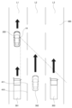
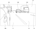
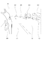
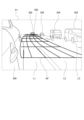
図1は本発明に係るキャリブレーション装置の一例であるカメラECU(Electronic Control Unit)30を含む、本発明に電子ミラーシステムの一例である電子ミラーシステム1を示すブロック図、図2は図1に示した電子ミラーシステム1を搭載した車両200(以下、自車200という。)が、例えば片側3車線のカーブしていない水平な道路400の左の車線L1を走行している状態を上方からの視点で模式的に表した図、図3は図2に示したカメラ10が撮影した画像を左右反転して表した画像P1の一例である。
<Configuration of electronic mirror system>
FIG. 1 is a block diagram showing an
図1に示した電子ミラーシステム1は、カメラ10と、車載ネットワーク(CAN:Controller Area Network)20と、カメラECU30と、モニタ90と、を備えている。
The
カメラ10は、自車200の左右のサイドミラーがそれぞれ取り付けられるべき両側部の位置に、左右のサイドミラーの代替としてそれぞれ設けられている。すなわち、カメラ10は左右に1つずつ設けられていて、各カメラ10は、自車200の主として設置された側の後方領域を撮影する。具体的は、図2に示すように、自車200の、矢印で示した進行方向の右側部に設けられたカメラ10は、自車200の右側の後方に向けて設置され、右側の後方の領域を撮影する。なお、図示を略しているが、自車200の、矢印で示した進行方向の左側部に設けられたカメラ10は、自車200の左側の後方に向けて設置され、左側の後方の領域を撮影する。
The
そして、図2に示した右側のカメラ10で撮影された画像を、左右反転すると、例えば、図3に示す画像P1となる。仮に、自車200に右のサイドミラーが設置されていた場合、自車200の運転者は、そのサイドミラーで反射した右側の後方の画像を視認するが、サイドミラーで反射した画像は、サイドミラーに入射した画像に対して左右反転する。
When the image captured by the
そして、サイドミラーに写った反射した画像を見慣れていた運転者にとっては、カメラ10で撮影された画像をそのままモニタ90に表示すると、サイドミラーで見慣れていた画像とは左右反転した画像であるため、違和感を覚えたり、混乱したりするおそれがある。
For a driver who is accustomed to seeing the image reflected in the side mirror, if the image captured by the
そこで、カメラECU30は、カメラ10で撮影された画像を左右反転する処理を施して、図3に示すように、左右反転した画像P1をモニタ90に表示させる。
Therefore, the
車載ネットワーク20は、自車200の各種情報(車速、操舵角、変速段等)を共有する回線である。
The in-
<カメラECUの構成>
カメラECU30は、道路状態検出部31と、記憶部32と、補正部33と、対象認識部34と、走行車線検出部35と、距離算出部36と、報知出力部37と、を備えている。
<Configuration of camera ECU>
The camera ECU 30 includes a road
道路状態検出部31は、自車200が走行している道路400のカーブの状態を検出する。具体的には、自車200が走行中の道路400において時系列的に異なる複数の時点でカメラ10によってそれぞれ撮影された左右反転した複数の画像P1に基づいて、カーブの状態を検出する。この実施形態においては、時系列的に異なる複数の時点でそれぞれカメラ10により撮影され左右反転した複数の画像P1における、道路400の車線L1,L2(図2参照)を区切る白線410の端点411(例えば、左上の角の点)の位置の、時系列的な変化に基づいて、道路400のカーブの程度を検出する。
Road
なお、道路状態検出部31は、白線410の端点411以外の撮影物の時系列的な位置の変化に基づいて、カーブの状態を検出するものであってもよい。
Note that the road
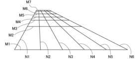
図4は記憶部32が記憶しているキャリブレーション用の格子40を示す模式図、図5はキャリブレーション用の格子40をカメラ10で撮影して左右反転した画像P1に重畳させたとき一例を示す模式図である。
FIG. 4 is a schematic diagram showing the
記憶部32には、図4に示すキャリブレーション用の格子40が記憶されている。この格子40は、自車200が走行している道路400が直線であると仮定した基準状態での、画像P1に写った道路400の路面上における各部分の、画像P1上における位置と現実空間での道路400に沿った位置との対応関係を表すテーブル(マップ)の一例である。
A
つまり、この格子40をカメラ10で写る画像P1に重畳させたとき、例えば図5に示すように、画像P1における道路400の路面上の各部の位置と格子40内の位置との対応づけにより、道路400の路面上の各部の位置(画像上の座標空間における位置)を現実空間における位置(現実空間の座標空間における位置)に対応づける。
That is, when the
図4に示した格子40は、カメラ10の画角や焦点距離、自車200への取り付け位置、向きなどの、いわゆるカメラパラメータに基づいて設定されている。格子40の横方向に延びる各線M1,M2,M3,M4,M5,M6,M7は、現実空間における自車200の前後方向の後方への等距離の間隔(現実空間において例えば10[m]間隔)に対応し、縦方向に延びる各線N1,N2,N3,N4,N5,N6は、現実空間における自車200の車幅方向への等距離の間隔(現実空間において例えば1[m]間隔)に対応している。つまり、格子40は、現実空間における自車の200の前後方向60[m]、車幅方向5[m]の矩形の領域対応している。
The
補正部33は、道路状態検出部31により検出された道路400のカーブの状態に基づいて、記憶部32に記憶された格子40を補正する。具体的には、例えば、道路状態検出部31が、道路400がカーブしていない直線の状態であると検出したときは、補正部33は、記憶部32に記憶された基準状態での格子40を補正せずに、図5に示すように、画像P1にそのまま重畳させる。
The
一方、例えば、道路状態検出部31により検出された道路400がカーブしているときは、補正部33は、検出された道路400のカーブに沿うように、基準状態での格子40を変形させる補正を行う。
On the other hand, for example, when the
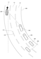
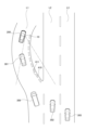
ここで、図6は自車200が、例えば片側3車線の右方向に緩やかにカーブしている水平な道路の左の車線L1を走行している状態を上方からの視点で模式的に表した図、図7は図6に示したカメラ10が撮影した画像P0を左右反転して表した画像P1の一例、図8は図6,7に示した道路400のカーブに沿うように補正された格子40′を図6に示した画像P1に重畳させた状態を示す図である。
Here, FIG. 6 schematically shows a state in which the
また、図9は自車200が、例えば片側2車線の高速道路から左側に分岐した側道の車線L1に出て、その側道の車線L1の右方向にカーブしているところを走行している状態を上方からの視点で模式的に表した図、図10は図9に示したカメラ10が撮影した画像P0を左右反転して表した画像P1の一例、図11は図9,10に示した道路400のカーブに沿うように補正された格子40′を図9に示した画像P1に重畳させた状態を示す図である。
In FIG. 9, the
例えば、道路状態検出部31が、道路400が図6,7に示すように緩やかに右方向にカーブしていると検出した場合、補正部33は、図7の画像P1に重畳させる格子40を、検出された道路400のカーブに沿った格子40′に変形させて、図8に示すように、図6の画像P1に重畳させる。これにより、道路400の路面上の各部分及び路面に接している対象物体の、現実空間における道路400のカーブに沿った自車200との位置関係を特定することができる。
For example, when the road
同様に、道路状態検出部31が、道路400が図9,10に示すように左側に分岐し他後に右方向にカーブしていると検出した場合、補正部33は、図10の画像P1に重畳させる格子40を、検出された道路400のカーブに沿った格子40′に変形させて、図11に示すように、図9の画像P1に重畳させる。これにより、道路400の路面上の各部分の、現実空間における道路400のカーブに沿った自車200との位置関係を特定することができる。
Similarly, when the road
対象認識部34は、図3,7,10等に示すように、画像P1に写った、自車200の後方を走行する後続車301,302,…(以下、後続車301等という。)を検出する。対象認識部34は、自動二輪等を含む車両の主に前面の輪郭形状や柄などのパターンを記憶部32に予め記憶していて、この記憶されたパターンを画像P1に対してパターンマッチング等により、後続車301等を検出する。また、対象認識部34は、検出した後続車301等の路面上の位置を検出することで、画像P1における後続車301等の位置を検出する。
As shown in FIGS. 3, 7, 10, etc., the
走行車線検出部35は、対象認識部34により認識された後続車301等の画像P1上の位置を、補正部33により補正して得られた格子40に基づいて、現実空間での道路400に沿った位置に変換して現実空間での道路400に沿った位置を特定し、現実空間における後続車301等が走行している車線を特定する。
The driving
すなわち、例えば、図3に示すように、道路400がカーブしていない直線の状態では、格子40は、基準状態での格子40のままであり、この基準状態での格子40を重畳した図5にしたがって、各後続車301等の現実空間で車線を特定する。
That is, for example, as shown in FIG. 3, when the
この場合、走行車線検出部35は、図5に示すように、後続車301は自車200と同じ車線L1を走行し、後続車302は自車200の走行車線L1の右に隣接する車線(隣接車線)L2を走行し、後続車303は隣接車線L2の右に隣接する車線(隣々接車線)L3を走行していると特定する。
In this case, as shown in FIG. 5, the driving
また、図8に示した場合、基準状態での格子40から格子40′に変形されているため、この変形された格子40′を重畳した状態にしたがって、走行車線検出部35は各後続車301等の現実空間で車線を特定する。
Further, in the case shown in FIG. 8, since the
この場合、走行車線検出部35は、図8に示すように、後続車302は自車200の走行車線L1の右に隣接する車線(隣接車線)L2を走行し、後続車303,304,305は隣接車線L2の右に隣接する車線(隣々接車線)L3を走行していると特定する。
In this case, as shown in FIG. 8, the traveling
同様に、図11に示した場合、基準状態での格子40から格子40′に変形されているため、この変形された格子40′を重畳した状態にしたがって、走行車線検出部35は各後続車301等の現実空間で車線を特定する。
Similarly, in the case shown in FIG. 11, since the
この場合、走行車線検出部35は、図11に示すように、後続車301,306は自車200と同じ車線L1を走行していると特定する。
In this case, the traveling
距離算出部36は、補正部33により補正して得られた格子40に基づいて、現実空間における自車200の位置と後続車301等の位置との、道路400のカーブに沿った距離を求める。
Based on the
報知出力部37は、走行車線検出部35により検出された後続車301等が走行している車線が、自車200が走行している車線L1に隣接する車線L2であり、かつ、距離算出部36により算出された距離が時系列的に短くなっているとき、すなわち隣接車線L2を走行している後続車が自車200に接近しているときは、後続車の接近を報知する信号をモニタ90に出力する。
The
モニタ90は、カメラ10で撮影された画像P0をカメラECU30により左右反転した画像P1を可視的に表示する。このとき、カメラECU30により、隣接車線L2を、自車200に接近するように自車200よりも走行速度の速い後続車を報知する信号が出力されているときは、モニタ90は、例えば図8に示すように、その検出した後続車302の周囲を囲む車両検知枠350を画像P1に重畳する。
The
<作用>
次に、本実施形態の電子ミラーシステム1の作用について説明する。自車200の右側部に設置されたカメラ10は、自車200の右後方の領域を所定の周期で撮影し、撮影された画像はカメラECU30に入力される。カメラECU30は、カメラ10から周期的に入力された各画像を、左右反転した画像P1に変換する。
<Action>
Next, the operation of the
カメラECU30に周期的に入力されて、それぞれ左右反転した複数の画像P1に基づいて、道路状態検出部31は、自車200が走行している道路400のカーブの状態を検出する。カーブの状態の検出は、図2に示した特定の白線410の端点411が、自車200の走行に伴って後方に移動していくときの時系列的に異なるタイミングで撮影された各画像P1上での位置の遷移によって求められる。
The road
図12は自車200の走行に伴って画像P1において、端点411が最初の位置R1から、位置R2′、位置R3′、位置R4′、位置R5′というように移動した様子を模式的に表したものである。道路状態検出部31は、画像P1上で経時的に移動していく端点411の位置R1,R2′,R3′,R4′,R5′を、例えば図12のXY直交座標の位置として検出する。
FIG. 12 schematically shows how the
なお、図12において、位置R1、位置R2、位置R3、位置R4、位置R5は、道路400がカーブしていない基準状態での、操舵角0[度]の自車200のその時の車速(CAN20から入力)により端点411が移動していくと予測される位置を表すものである。この予測の位置R1,R2,R3,R4,R5は、車載ネットワーク20から入力された自車200の車速を用いて、操舵角0[度]を前提としたものである。この基準状態での予測の位置R1,R2,R3,R4,R5は、一直線上に並ぶ。
In FIG. 12, positions R1, R2, R3, R4, and R5 are vehicle speeds (CAN20 (input from ) represents the position where the
しかし、道路状態検出部31によって検出された位置R1,R2′,R3′,R4′,R5′は一直線上に並ばずに、位置R2′は位置R2からX軸方向及びY軸方向にそれぞれずれ、その後の位置R3′,R4′,R5′もそれぞれ対応する位置R3,R4,R5からX軸方向及びY軸方向にずれている。このX軸方向及びY軸方向への位置ずれは、自車200の向きが時系列的に変化していること、すなわち自車200が走行している道路400がカーブしていることを示している。
However, the positions R1, R2', R3', R4', and R5' detected by the road
補正部33は、道路状態検出部31で検出された、この道路400のカーブの状態に基づいて、キャリブレーション用の格子40を補正する。
The
具体的には、道路状態検出部31で検出された位置R2′が基準状態での予測された位置R2からの、X軸方向に位置ずれているずれ量ΔR2x(図12のX軸の傍に記載。以下、同じ。)とY軸方向に位置ずれているずれ量ΔR2y(図12のY軸の傍に記載。以下、同じ。)、位置R3′が基準状態での予測された位置R3からの、X軸方向に位置ずれているずれ量ΔR3xとY軸方向に位置ずれているずれ量ΔR3y、R4′が基準状態での予測された位置R4からの、X軸方向に位置ずれているずれ量ΔR4xとY軸方向に位置ずれているずれ量ΔR4y、R5′が基準状態での予測された位置R5からの、X軸方向に位置ずれているずれ量ΔR5xとY軸方向に位置ずれているずれ量ΔR5yに基づいて、図2に示した格子40を変形させる。
Specifically, the position R2' detected by the road
このとき、格子40内の、位置R2,R3,R4,R5以外の他の位置の移動先の位置は、これら位置R2,R3,R4,R5の移動先の位置R2′,R3′,R4′,R5′を代表点として算出することが可能であり、これにより、格子40を、カーブした道路400に沿うように変形させることができる。
At this time, the destination positions of the positions other than the positions R2, R3, R4 and R5 in the
これにより、自車200車に設けられたカメラ10の画像P1に基づいて、カメラ10の画像P1に写った後続車の、現実空間における、道路400のカーブに沿った自車200との位置関係を正確に求めることができる。
As a result, based on the image P1 of the
なお、道路400のカーブによる格子40内の位置の移動量は、自車200の直近の後方においては少なく、自車200から遠い程大きくなるため、格子40の変形のための補正量の算出は、図12に示した、自車200の後方の一部の領域P2のみを対象として算出してもよい。これにより、補正のための演算量を低減し、演算負荷を手抑制することができる。リソースの限られた車両という移動体に搭載されたカメラECU30としては、演算負荷の抑制は、重要な課題の一つである。
Note that the amount of movement of the position within the
一方、対象認識部34は、画像P1から後続車を検出する。走行車線検出部35は、その後続車が走行している車線を、補正された格子40′に基づいて特定する。
On the other hand, the
同様に、距離算出部36は、自車200から画像P1において検出された後続車までの、道路400のカーブに沿った距離を、補正された格子40′に基づいて求める。
Similarly, the
このようにして、カメラECU30は、検出された各後続車が走行する車線と、自車200から各後続車までの道路400のカーブに沿った距離とを特定する。そして、報知出力部37は、検出された後続車のうち、自車200が走行する車線L1に隣接する車線L2を走行するとともに、その隣接する車線L2を走行する後続車と自車との、道路400のカーブに沿った距離が、時系列的に縮まっているとき、すなわち、報知出力部37は、自車200に近づいてくる隣接車線L2を走行する後続車が検出したときは、モニタ90に対して報知信号を出力する。
In this way, the
モニタ90は、その報知信号の対象となる、隣接車線L2を走行して自車に近づいてくる後続車については、図8に示すように、その後続車302の周囲を囲む車両検知枠350を画像P1に重畳して表示する。
As shown in FIG. 8, the
これにより、モニタ90を見た自車200の運転者に対して、隣接車線L2への車線変更を行わないように注意を喚起することができる。
As a result, the driver of
一方、報知出力部37は、検出された後続車のうち、自車200が走行する車線L1を走行している後続車や、隣々接車線L3を走行している後続車については、その後続車が自車200に近づいてくるものであっても、報知信号を出力しない。同様に、隣接車線L2を走行する後続車であっても、その後続車が自車200に近づいていないときも、報知出力部37は報知信号を出力しない。
On the other hand, among the detected following vehicles, the
モニタ90は、報知出力部37から報知信号の出力が無いため、いずれの後続車に対しても、運転者の注意を喚起する車両検知枠350を付加することなく画像P1を表示する。
Since there is no notification signal output from the
これにより、モニタ90を見た自車200の運転者に対して、隣接車線L2への車線変更を行わないようにとの無用な注意喚起を行わないようにすることができ、運転者への不必要な報知の頻発を防止又は抑制することができる。
As a result, the driver of the
以上のように、本実施形態のカメラECU30及び電子ミラーシステム1によれば、自車200に設けられたカメラ10の画像P1に基づいて、カメラ10の画像P1に写った後続車301等の、現実空間における道路400に沿った自車200との位置関係を正確に求めることができる。
As described above, according to the
なお、本実施形態は、自車200の右側に設けられたカメラ10で撮影された、自車200の主に右後方の後続車と自車200との位置関係についてのみ説明したが、自車200の左側に設けられたカメラ10で撮影された、自車200の主に左後方の後続車と自車200との位置関係について、同様に実施される。
In the present embodiment, only the positional relationship between the following vehicle on the right rear of the
また、本実施形態は、自車200よりも後方に存在する後続車と自車200との位置関係についてのみ説明したが、本発明に係るキャリブレーション装置及び電子ミラーシステムは、後続車だけでなく、自車200よりも前方に存在する先行車と自車200との位置関係についても同様に適用可能である。この場合は、カメラは自車の前方を向いたカメラを適用する。
Also, in the present embodiment, only the positional relationship between the following vehicle existing behind the
上述した実施形態は、道路400の曲がり具合に対応して格子40を変形させ、画像P1での後続車の位置を、変形した格子40′で表された車線に沿わせた車線、距離で求めているが、画像P1を、変形した格子40′の横方向の線M1,M2,…と縦方向の線N1,N2,…とで特定される別の座標系の画像に変換し、その変換して得られた別の座標系の画像上で、後続車の位置(車線、自車200からの距離等)を特定してもよい。
In the above-described embodiment, the
1 電子ミラーシステム
10 カメラ
30 カメラECU
31 道路状態検出部
32 記憶部
33 補正部
40 格子
200 車両(自車)
400 道路
L2 隣接車線
1
31 road
400 Road L2 Adjacent lane
Claims (5)
前記自車が走行している前記道路が直線であると仮定した基準状態での、画像に写った前記道路の路面上における各部分の、前記画像上における位置と、現実空間での前記道路に沿った位置との対応関係を記憶した記憶部と、
前記道路状態検出部により、前記車線を区切る線の角の点の位置の時系列的な変化に基づいて検出された前記道路のカーブの状態と、前記自車が走行している前記道路が直線であると仮定した前記基準状態において前記車線を区切る線の角の点の位置が移動していくと予測される位置とを比較してずれ量を算出し、前記記憶部に記憶された前記対応関係を、前記ずれ量に応じて補正する補正部と、
前記画像に写った他車を検出する対象認識部と、
前記補正部により補正して得られた前記画像上の前記座標位置と前記現実空間での座標位置との前記対応関係に基づいて、前記対象認識部により認識された前記他車の、前記現実空間での前記道路に沿った位置を特定し、前記現実空間における前記自車と前記他車との前記道路に沿った距離を求める距離算出部と、を備えたキャリブレーション装置。 Positions of points at the corners of lines separating lanes in a plurality of images captured by a camera mounted on the vehicle at a plurality of time-series different points in time on the road on which the vehicle is traveling. a road condition detection unit that detects the curve condition of the road based on the change in
Positions on the image of each part on the road surface of the road captured in the image and real space in a reference state assuming that the road on which the vehicle is traveling is straight a storage unit that stores correspondence relationships with positions along the road ;
The curve state of the road detected by the road state detection unit based on the time-series change in the position of the corner point of the line separating the lanes, and the state of the road on which the vehicle is traveling The position of the corner point of the line separating the lanes is compared with the position predicted to move in the reference state assuming that the road is straight, and the amount of deviation is calculated and stored in the storage unit. a correction unit that corrects the corresponding relationship according to the amount of deviation;
a target recognition unit that detects another vehicle in the image;
The real space of the other vehicle recognized by the object recognition unit based on the correspondence relationship between the coordinate position on the image obtained by the correction by the correction unit and the coordinate position in the real space. and a distance calculation unit that specifies a position along the road in the real space and calculates a distance along the road between the own vehicle and the other vehicle in the real space.
前記走行車線検出部により検出された前記他車が走行している車線が、前記自車が走行している車線に隣接する車線であり、かつ、前記距離算出部により算出された距離が時系列的に短くなっているときは、前記他車の接近を報知する信号を出力する報知出力部と、を備えた請求項1又は2に記載のキャリブレーション装置。 a driving lane detection unit that identifies the lane in which the other vehicle is driving in the physical space based on the correspondence obtained by the correction by the correction unit;
The lane in which the other vehicle is traveling detected by the traveling lane detection unit is a lane adjacent to the lane in which the own vehicle is traveling, and the distance calculated by the distance calculation unit is in time series. 3. The calibration device according to claim 1, further comprising a notification output unit for outputting a signal for notifying that the other vehicle is approaching when the time is short.
前記カメラで撮影された画像を、前記反射鏡で反射して見たように左右反転した画像を表示する、前記自車の車室に設けられた画像表示装置と、
請求項4に記載のキャリブレーション装置と、を備え、
前記画像表示装置は、前記報知出力部から出力された信号により、接近する前記他車を強調する表示を行う電子ミラーシステム。 a camera mounted on the own vehicle and provided at a portion where a reflecting mirror should be provided, for photographing the exterior of the own vehicle;
an image display device provided in the passenger compartment of the own vehicle for displaying an image photographed by the camera that is horizontally reversed as if it were reflected by the reflecting mirror;
A calibration device according to claim 4,
The image display device is an electronic mirror system that performs display emphasizing the approaching other vehicle based on the signal output from the notification output unit.
Priority Applications (2)
| Application Number | Priority Date | Filing Date | Title |
|---|---|---|---|
| JP2018109139A JP7226930B2 (en) | 2018-06-07 | 2018-06-07 | Calibration device and electronic mirror system |
| PCT/JP2019/008266 WO2019235004A1 (en) | 2018-06-07 | 2019-03-04 | Calibration device and electronic mirror system |
Applications Claiming Priority (1)
| Application Number | Priority Date | Filing Date | Title |
|---|---|---|---|
| JP2018109139A JP7226930B2 (en) | 2018-06-07 | 2018-06-07 | Calibration device and electronic mirror system |
Publications (3)
| Publication Number | Publication Date |
|---|---|
| JP2019213108A JP2019213108A (en) | 2019-12-12 |
| JP2019213108A5 JP2019213108A5 (en) | 2021-05-27 |
| JP7226930B2 true JP7226930B2 (en) | 2023-02-21 |
Family
ID=68770232
Family Applications (1)
| Application Number | Title | Priority Date | Filing Date |
|---|---|---|---|
| JP2018109139A Active JP7226930B2 (en) | 2018-06-07 | 2018-06-07 | Calibration device and electronic mirror system |
Country Status (2)
| Country | Link |
|---|---|
| JP (1) | JP7226930B2 (en) |
| WO (1) | WO2019235004A1 (en) |
Families Citing this family (2)
| Publication number | Priority date | Publication date | Assignee | Title |
|---|---|---|---|---|
| JP7304334B2 (en) | 2020-12-03 | 2023-07-06 | 本田技研工業株式会社 | VEHICLE CONTROL DEVICE, VEHICLE CONTROL METHOD, AND PROGRAM |
| CN113911035B (en) * | 2021-11-08 | 2023-08-25 | 广州优创电子有限公司 | Intelligent rearview mirror and intelligent rearview mirror control method |
Citations (4)
| Publication number | Priority date | Publication date | Assignee | Title |
|---|---|---|---|---|
| JP2007164636A (en) | 2005-12-15 | 2007-06-28 | Toyota Motor Corp | Lane line detection device |
| JP2007264955A (en) | 2006-03-28 | 2007-10-11 | Fuji Heavy Ind Ltd | Lane position detector |
| WO2012147187A1 (en) | 2011-04-27 | 2012-11-01 | トヨタ自動車株式会社 | Periphery vehicle detection device |
| JP2015028696A (en) | 2013-07-30 | 2015-02-12 | アルパイン株式会社 | Vehicle rear side alarm device, vehicle rear side alarm method and other vehicles distance detection device |
Family Cites Families (1)
| Publication number | Priority date | Publication date | Assignee | Title |
|---|---|---|---|---|
| JP3431678B2 (en) * | 1994-02-14 | 2003-07-28 | 三菱自動車工業株式会社 | Ambient situation display device for vehicles |
-
2018
- 2018-06-07 JP JP2018109139A patent/JP7226930B2/en active Active
-
2019
- 2019-03-04 WO PCT/JP2019/008266 patent/WO2019235004A1/en active Application Filing
Patent Citations (4)
| Publication number | Priority date | Publication date | Assignee | Title |
|---|---|---|---|---|
| JP2007164636A (en) | 2005-12-15 | 2007-06-28 | Toyota Motor Corp | Lane line detection device |
| JP2007264955A (en) | 2006-03-28 | 2007-10-11 | Fuji Heavy Ind Ltd | Lane position detector |
| WO2012147187A1 (en) | 2011-04-27 | 2012-11-01 | トヨタ自動車株式会社 | Periphery vehicle detection device |
| JP2015028696A (en) | 2013-07-30 | 2015-02-12 | アルパイン株式会社 | Vehicle rear side alarm device, vehicle rear side alarm method and other vehicles distance detection device |
Also Published As
| Publication number | Publication date |
|---|---|
| JP2019213108A (en) | 2019-12-12 |
| WO2019235004A1 (en) | 2019-12-12 |
Similar Documents
| Publication | Publication Date | Title |
|---|---|---|
| JP5229451B2 (en) | Automobile lane departure prevention method | |
| US11210533B1 (en) | Method of predicting trajectory of vehicle | |
| JP6410198B1 (en) | Ranging system and mobile system | |
| JP5863607B2 (en) | Pedestrian warning device | |
| JP5011049B2 (en) | Image processing system | |
| US10166923B2 (en) | Image generation device and image generation method | |
| JP6586849B2 (en) | Information display device and information display method | |
| JP6778620B2 (en) | Road marking device, road marking system, and road marking method | |
| CN111034186B (en) | Surrounding vehicle display method and surrounding vehicle display device | |
| TWI533694B (en) | Obstacle detection and display system for vehicle | |
| JP2011065219A (en) | Device for estimation of road curvature | |
| US9902341B2 (en) | Image processing apparatus and image processing method including area setting and perspective conversion | |
| JP2012166705A (en) | Foreign matter attachment determining system for on-vehicle camera lens | |
| JP7226930B2 (en) | Calibration device and electronic mirror system | |
| CN103381825B (en) | Use the full speed lane sensing of multiple photographic camera | |
| JP2016021712A (en) | Image processing system and operation support system | |
| US20230140228A1 (en) | Image control system | |
| JP6032141B2 (en) | Travel road marking detection device and travel road marking detection method | |
| JP6439233B2 (en) | Image display apparatus for vehicle and image processing method | |
| JP6824759B2 (en) | Bound line detection device, lane marking system, and lane marking method | |
| JP5831331B2 (en) | Rear side photographing device for vehicle | |
| US11938870B2 (en) | Vehicle compound-eye camera | |
| JP2019133580A (en) | Section line detection device, section line detection system, and section line detection method | |
| CN115943287A (en) | Vehicle attitude estimation system and vehicle attitude estimation method | |
| JP4598011B2 (en) | Vehicle display device |
Legal Events
| Date | Code | Title | Description |
|---|---|---|---|
| A521 | Request for written amendment filed |
Free format text: JAPANESE INTERMEDIATE CODE: A523 Effective date: 20210412 |
|
| A621 | Written request for application examination |
Free format text: JAPANESE INTERMEDIATE CODE: A621 Effective date: 20210412 |
|
| A131 | Notification of reasons for refusal |
Free format text: JAPANESE INTERMEDIATE CODE: A131 Effective date: 20220607 |
|
| A521 | Request for written amendment filed |
Free format text: JAPANESE INTERMEDIATE CODE: A523 Effective date: 20220805 |
|
| A131 | Notification of reasons for refusal |
Free format text: JAPANESE INTERMEDIATE CODE: A131 Effective date: 20220913 |
|
| A521 | Request for written amendment filed |
Free format text: JAPANESE INTERMEDIATE CODE: A523 Effective date: 20221110 |
|
| TRDD | Decision of grant or rejection written | ||
| A01 | Written decision to grant a patent or to grant a registration (utility model) |
Free format text: JAPANESE INTERMEDIATE CODE: A01 Effective date: 20230117 |
|
| A61 | First payment of annual fees (during grant procedure) |
Free format text: JAPANESE INTERMEDIATE CODE: A61 Effective date: 20230209 |
|
| R150 | Certificate of patent or registration of utility model |
Ref document number: 7226930 Country of ref document: JP Free format text: JAPANESE INTERMEDIATE CODE: R150 |