JP7226544B2 - VEHICLE TRIP CONTROL METHOD AND TRIP CONTROL DEVICE - Google Patents
VEHICLE TRIP CONTROL METHOD AND TRIP CONTROL DEVICE Download PDFInfo
- Publication number
- JP7226544B2 JP7226544B2 JP2021525388A JP2021525388A JP7226544B2 JP 7226544 B2 JP7226544 B2 JP 7226544B2 JP 2021525388 A JP2021525388 A JP 2021525388A JP 2021525388 A JP2021525388 A JP 2021525388A JP 7226544 B2 JP7226544 B2 JP 7226544B2
- Authority
- JP
- Japan
- Prior art keywords
- vehicle
- travel
- lane
- trajectory
- override
- Prior art date
- Legal status (The legal status is an assumption and is not a legal conclusion. Google has not performed a legal analysis and makes no representation as to the accuracy of the status listed.)
- Active
Links
- 238000000034 method Methods 0.000 title claims description 27
- 230000002194 synthesizing effect Effects 0.000 claims description 4
- 230000006399 behavior Effects 0.000 description 16
- 238000010586 diagram Methods 0.000 description 4
- 238000001514 detection method Methods 0.000 description 3
- 230000015572 biosynthetic process Effects 0.000 description 2
- 238000003786 synthesis reaction Methods 0.000 description 2
- 230000006870 function Effects 0.000 description 1
Images


Classifications
-
- G—PHYSICS
- G01—MEASURING; TESTING
- G01C—MEASURING DISTANCES, LEVELS OR BEARINGS; SURVEYING; NAVIGATION; GYROSCOPIC INSTRUMENTS; PHOTOGRAMMETRY OR VIDEOGRAMMETRY
- G01C21/00—Navigation; Navigational instruments not provided for in groups G01C1/00 - G01C19/00
- G01C21/26—Navigation; Navigational instruments not provided for in groups G01C1/00 - G01C19/00 specially adapted for navigation in a road network
- G01C21/34—Route searching; Route guidance
- G01C21/36—Input/output arrangements for on-board computers
- G01C21/3626—Details of the output of route guidance instructions
- G01C21/3658—Lane guidance
-
- B—PERFORMING OPERATIONS; TRANSPORTING
- B60—VEHICLES IN GENERAL
- B60W—CONJOINT CONTROL OF VEHICLE SUB-UNITS OF DIFFERENT TYPE OR DIFFERENT FUNCTION; CONTROL SYSTEMS SPECIALLY ADAPTED FOR HYBRID VEHICLES; ROAD VEHICLE DRIVE CONTROL SYSTEMS FOR PURPOSES NOT RELATED TO THE CONTROL OF A PARTICULAR SUB-UNIT
- B60W60/00—Drive control systems specially adapted for autonomous road vehicles
- B60W60/007—Emergency override
-
- B—PERFORMING OPERATIONS; TRANSPORTING
- B60—VEHICLES IN GENERAL
- B60W—CONJOINT CONTROL OF VEHICLE SUB-UNITS OF DIFFERENT TYPE OR DIFFERENT FUNCTION; CONTROL SYSTEMS SPECIALLY ADAPTED FOR HYBRID VEHICLES; ROAD VEHICLE DRIVE CONTROL SYSTEMS FOR PURPOSES NOT RELATED TO THE CONTROL OF A PARTICULAR SUB-UNIT
- B60W30/00—Purposes of road vehicle drive control systems not related to the control of a particular sub-unit, e.g. of systems using conjoint control of vehicle sub-units
- B60W30/10—Path keeping
-
- B—PERFORMING OPERATIONS; TRANSPORTING
- B60—VEHICLES IN GENERAL
- B60W—CONJOINT CONTROL OF VEHICLE SUB-UNITS OF DIFFERENT TYPE OR DIFFERENT FUNCTION; CONTROL SYSTEMS SPECIALLY ADAPTED FOR HYBRID VEHICLES; ROAD VEHICLE DRIVE CONTROL SYSTEMS FOR PURPOSES NOT RELATED TO THE CONTROL OF A PARTICULAR SUB-UNIT
- B60W30/00—Purposes of road vehicle drive control systems not related to the control of a particular sub-unit, e.g. of systems using conjoint control of vehicle sub-units
- B60W30/18—Propelling the vehicle
- B60W30/18009—Propelling the vehicle related to particular drive situations
- B60W30/18163—Lane change; Overtaking manoeuvres
-
- B—PERFORMING OPERATIONS; TRANSPORTING
- B60—VEHICLES IN GENERAL
- B60W—CONJOINT CONTROL OF VEHICLE SUB-UNITS OF DIFFERENT TYPE OR DIFFERENT FUNCTION; CONTROL SYSTEMS SPECIALLY ADAPTED FOR HYBRID VEHICLES; ROAD VEHICLE DRIVE CONTROL SYSTEMS FOR PURPOSES NOT RELATED TO THE CONTROL OF A PARTICULAR SUB-UNIT
- B60W60/00—Drive control systems specially adapted for autonomous road vehicles
- B60W60/001—Planning or execution of driving tasks
-
- B—PERFORMING OPERATIONS; TRANSPORTING
- B62—LAND VEHICLES FOR TRAVELLING OTHERWISE THAN ON RAILS
- B62D—MOTOR VEHICLES; TRAILERS
- B62D15/00—Steering not otherwise provided for
- B62D15/02—Steering position indicators ; Steering position determination; Steering aids
- B62D15/025—Active steering aids, e.g. helping the driver by actively influencing the steering system after environment evaluation
- B62D15/0255—Automatic changing of lane, e.g. for passing another vehicle
-
- G—PHYSICS
- G01—MEASURING; TESTING
- G01C—MEASURING DISTANCES, LEVELS OR BEARINGS; SURVEYING; NAVIGATION; GYROSCOPIC INSTRUMENTS; PHOTOGRAMMETRY OR VIDEOGRAMMETRY
- G01C21/00—Navigation; Navigational instruments not provided for in groups G01C1/00 - G01C19/00
- G01C21/26—Navigation; Navigational instruments not provided for in groups G01C1/00 - G01C19/00 specially adapted for navigation in a road network
- G01C21/34—Route searching; Route guidance
- G01C21/3407—Route searching; Route guidance specially adapted for specific applications
-
- G—PHYSICS
- G08—SIGNALLING
- G08G—TRAFFIC CONTROL SYSTEMS
- G08G1/00—Traffic control systems for road vehicles
- G08G1/16—Anti-collision systems
- G08G1/167—Driving aids for lane monitoring, lane changing, e.g. blind spot detection
-
- B—PERFORMING OPERATIONS; TRANSPORTING
- B60—VEHICLES IN GENERAL
- B60W—CONJOINT CONTROL OF VEHICLE SUB-UNITS OF DIFFERENT TYPE OR DIFFERENT FUNCTION; CONTROL SYSTEMS SPECIALLY ADAPTED FOR HYBRID VEHICLES; ROAD VEHICLE DRIVE CONTROL SYSTEMS FOR PURPOSES NOT RELATED TO THE CONTROL OF A PARTICULAR SUB-UNIT
- B60W2520/00—Input parameters relating to overall vehicle dynamics
- B60W2520/06—Direction of travel
-
- B—PERFORMING OPERATIONS; TRANSPORTING
- B60—VEHICLES IN GENERAL
- B60W—CONJOINT CONTROL OF VEHICLE SUB-UNITS OF DIFFERENT TYPE OR DIFFERENT FUNCTION; CONTROL SYSTEMS SPECIALLY ADAPTED FOR HYBRID VEHICLES; ROAD VEHICLE DRIVE CONTROL SYSTEMS FOR PURPOSES NOT RELATED TO THE CONTROL OF A PARTICULAR SUB-UNIT
- B60W2520/00—Input parameters relating to overall vehicle dynamics
- B60W2520/10—Longitudinal speed
-
- B—PERFORMING OPERATIONS; TRANSPORTING
- B60—VEHICLES IN GENERAL
- B60W—CONJOINT CONTROL OF VEHICLE SUB-UNITS OF DIFFERENT TYPE OR DIFFERENT FUNCTION; CONTROL SYSTEMS SPECIALLY ADAPTED FOR HYBRID VEHICLES; ROAD VEHICLE DRIVE CONTROL SYSTEMS FOR PURPOSES NOT RELATED TO THE CONTROL OF A PARTICULAR SUB-UNIT
- B60W2520/00—Input parameters relating to overall vehicle dynamics
- B60W2520/14—Yaw
-
- B—PERFORMING OPERATIONS; TRANSPORTING
- B60—VEHICLES IN GENERAL
- B60W—CONJOINT CONTROL OF VEHICLE SUB-UNITS OF DIFFERENT TYPE OR DIFFERENT FUNCTION; CONTROL SYSTEMS SPECIALLY ADAPTED FOR HYBRID VEHICLES; ROAD VEHICLE DRIVE CONTROL SYSTEMS FOR PURPOSES NOT RELATED TO THE CONTROL OF A PARTICULAR SUB-UNIT
- B60W2540/00—Input parameters relating to occupants
- B60W2540/18—Steering angle
-
- B—PERFORMING OPERATIONS; TRANSPORTING
- B60—VEHICLES IN GENERAL
- B60W—CONJOINT CONTROL OF VEHICLE SUB-UNITS OF DIFFERENT TYPE OR DIFFERENT FUNCTION; CONTROL SYSTEMS SPECIALLY ADAPTED FOR HYBRID VEHICLES; ROAD VEHICLE DRIVE CONTROL SYSTEMS FOR PURPOSES NOT RELATED TO THE CONTROL OF A PARTICULAR SUB-UNIT
- B60W2552/00—Input parameters relating to infrastructure
- B60W2552/10—Number of lanes
-
- B—PERFORMING OPERATIONS; TRANSPORTING
- B60—VEHICLES IN GENERAL
- B60W—CONJOINT CONTROL OF VEHICLE SUB-UNITS OF DIFFERENT TYPE OR DIFFERENT FUNCTION; CONTROL SYSTEMS SPECIALLY ADAPTED FOR HYBRID VEHICLES; ROAD VEHICLE DRIVE CONTROL SYSTEMS FOR PURPOSES NOT RELATED TO THE CONTROL OF A PARTICULAR SUB-UNIT
- B60W2720/00—Output or target parameters relating to overall vehicle dynamics
- B60W2720/10—Longitudinal speed
Landscapes
- Engineering & Computer Science (AREA)
- Automation & Control Theory (AREA)
- Radar, Positioning & Navigation (AREA)
- Remote Sensing (AREA)
- Mechanical Engineering (AREA)
- Transportation (AREA)
- Physics & Mathematics (AREA)
- General Physics & Mathematics (AREA)
- Human Computer Interaction (AREA)
- Chemical & Material Sciences (AREA)
- Combustion & Propulsion (AREA)
- Steering Control In Accordance With Driving Conditions (AREA)
- Control Of Driving Devices And Active Controlling Of Vehicle (AREA)
- Traffic Control Systems (AREA)
Description
本発明は、自車両の走行を制御するための車両の走行制御方法及び走行制御装置に関するものである。 BACKGROUND OF THE
走行制御装置によって自車両が目標軌道に追従して自律走行を行うための自動運転制御が実行される場合、目標軌道上に路駐車等の障害物が存在すると、ドライバのステアリング操作の介入により障害物を回避する必要がある。この場合、自車両の走行制御は、手動運転制御が自動運転制御に優先するオーバーライドの状態となる。従来の走行制御装置は、自車両のオーバーライド時に、自動運転制御による操舵制御の指令値を、ドライバの意図に応じて補正するものであった。 When automatic driving control is executed by the cruise control device so that the vehicle follows the target trajectory and runs autonomously, if there is an obstacle such as road parking on the target trajectory, the driver's steering operation will cause the obstacle. Things have to be avoided. In this case, the running control of the host vehicle is in an override state in which the manual driving control has priority over the automatic driving control. A conventional cruise control device corrects a command value for steering control by automatic driving control according to the intention of the driver when the own vehicle overrides.
しかしながら、特許文献1のステアリング装置では、オーバーライドによる自車両の車線変更が考慮されていない。そのため、ドライバによる手動運転制御の介入によって自車両が車線変更する場合に、手動運転制御と自動運転制御との切り替わりがスムーズに行われず、車両の挙動が安定しない可能性があった。 However, the steering device of
本発明が解決しようとする課題は、自律走行を行う自車両がオーバーライドによって車線変更する場合に、自車両の挙動を安定させることができる車両の走行制御方法及び走行制御装置を提供することである。 SUMMARY OF THE INVENTION The problem to be solved by the present invention is to provide a vehicle cruise control method and a cruise control device that can stabilize the behavior of a vehicle that is traveling autonomously and that changes lanes by means of an override. .
本発明は、自律走行する自車両が、オーバーライドによって車線変更する場合、自車両のオーバーライドを考慮した軌道を生成し、自車両が生成された軌道に沿って走行して車線変更を行うように自車両の挙動を制御することによって上記課題を解決する。 According to the present invention, when an autonomously traveling own vehicle changes lanes due to an override, a trajectory is generated in consideration of the override of the own vehicle, and the own vehicle travels along the generated trajectory to change lanes. The above problem is solved by controlling the behavior of the vehicle.
本発明によれば、オーバーライドを考慮して生成された軌道に自車両が追従するため、自律走行を行う自車両がオーバーライドによって車線変更する場合に、自車両の挙動を安定させることができる、という効果を奏する。 According to the present invention, since the own vehicle follows the trajectory generated in consideration of the override, the behavior of the own vehicle can be stabilized when the own vehicle performing autonomous driving changes lanes due to the override. Effective.
《第1実施形態》
以下、本発明の最良の実施形態である第1実施形態に係る車両の走行制御装置100について、図1~4に基づいて、説明する。
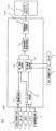
図1に示すように、走行制御システム111は、自車両101を自律走行させるための自動運転制御を実行する走行制御装置100を有している。走行制御システム111は、メモリ2、ロケータ3、カメラ4、LRF(Laser Range Finder,レーザレンジファインダ)5、操舵量検出部6及びステアリングアクチュエータ7を含む。走行制御装置100は、メモリ2、ロケータ3、カメラ4、LRF5及び操舵量検出部6から取得した情報に基づいて、自車両101が自律走行できるように、ステアリングアクチュエータ7を含む各種アクチュエータを制御する。<<1st Embodiment>>
A vehicle running
As shown in FIG. 1, the
メモリ2には、データ取得用車両を用いて実際の道路を走行した際に検出された道路形状に基づく三次元高精細地図情報が格納されている。このメモリ2が記憶する三次元高精細地図情報には、地図情報とともに、各地図座標における境界情報、二次元位置情報、三次元位置情報、道路情報、道路属性情報、上り情報、下り情報、レーン識別情報、接続先レーン情報等が含まれている。道路情報及び道路属性には、道路幅、曲率半径、路肩構造物、道路交通法規(制限速度、車線変更の可否)、道路の合流地点、分岐地点、料金所、車線数の減少位置、サービスエリア/パーキングエリア等の情報が含まれている。 The
ロケータ3は、GPSユニット、ジャイロセンサ、及び車速センサ等から構成される。ロケータ3は、GPSユニットにより複数の衛星通信から送信される電波を検出し、自車両101の位置情報を周期的に取得するとともに、取得した自車両101の位置情報と、ジャイロセンサから取得した角度変化情報と、車速センサから取得した車速とに基づいて、自車両101の現在の位置情報を周期的に検出する。 The
カメラ4は、CCD広角カメラ等のイメージセンサからなり、自車両101に前方、後方及び必要に応じて両側方に設けられ、自車両101の周囲を撮像して画像情報を取得する。カメラ4は、ステレオカメラや全方位カメラであってもよく、複数のイメージセンサを含むようにしてもよい。カメラ4は、取得した画像データから、自車両101の前方に存在する道路及び道路周辺の構造物、道路標示、標識、他車両、二輪車、自転車、歩行者等を自車両101の周囲状況として検出する。 The
LRF5は、自車両101の前方、後方及び両側方に設けられ、ミリ波又は超音波を自車両101の周囲に照射して自車両101の周囲の所定範囲を走査する。これにより、LRF5は、自車両101の周囲に存在する他車両、二輪車、自転車、歩行者、路肩の縁石、ガードレール、壁面、盛り土等の障害物を検出する。例えば、LRF5は、障害物と自車両101との相対位置(方位)、障害物の相対速度、自車両101から障害物までの距離等を自車両101の周囲状況として検出する。 The LRFs 5 are provided on the front, rear, and both sides of the
操舵量検出部6は、例えば、ステアリングシャフト(図示せず)の回転角を検出するセンサであり、自車両101の操舵量を検出する。 The steering
ステアリングアクチュエータ7は、例えばステアリングシャフトにトルクを伝達可能なモータからなり、走行制御装置100による自動運転制御の指令値又はドライバによるステアリングホイール103の操作に応じて、自車両101の操舵を制御する。 The
走行制御装置100は、一又は複数のコンピュータ及び当該コンピュータにインストールされたソフトウェアにより構成される。走行制御装置100は、自動運転制御機能を発揮させるためのプログラムを格納したROMと、このROMに格納されたプログラムを実行するCPUと、アクセス可能な記憶装置として機能するRAMとから構成される。走行制御装置100は、車線計画部10、オーバーライド判定部20、第1走行可能領域生成部31、第2走行可能領域生成部41、合成部45、自車両走行軌道生成部50及び経路追従制御部60を有している。 The
次に、走行制御装置100による全体的な制御の概要について、図2を用いて説明する。
まず、走行制御装置100は、ロケータ3によって得られた自車両9の位置情報及びメモリ2の地図情報により、自己位置の推定を行う(ステップS1)。また、走行制御装置100は、カメラ4及びLRF5によって、自車両101の周囲の歩行者その他の障害物を認識する(ステップS2)。そして、ステップS1で推定された自己位置の情報と、ステップS2で認識された障害物等の情報とが、メモリ2に格納された地図情報の上に展開される(ステップS3)。Next, an overview of overall control by the
First, the
さらに、ドライバにより目的地が入力され、自律走行制御の開始指示が入力されると、メモリ2の地図情報上に目的地が設定され(ステップS4)、現在地から目的地までのルートプランニングがなされる(ステップS5)。そして、地図情報に基づいて、自車両101の行動が決定される(ステップS6)。具体的には、たとえばプラニングされたルートに存在する複数の交差点の各位置において、自車両101がどの方向に曲がるか等が決定される。そして次に、メモリ2の地図情報上において、ドライブゾーンプランニングが行われる(ステップS7)。具体的には、ルート上の所定位置又は所定間隔において、自車両101がどの車線を走行するべきかが適宜設定される。そして、走行制御装置100は、入力された現在地及び目的地の位置情報、設定されたルート情報、ドライブゾーンの情報、カメラ4及びLRF5により認識された障害物の情報等に基づいて、自車両101の目標軌道を設定する(ステップS8)。さらに、走行制御装置100は、目標軌道に自車両101が追従するように、自車両101の各種アクチュエータの挙動を制御する(ステップS9)。 Further, when the driver inputs a destination and an instruction to start autonomous driving control, the destination is set on the map information in the memory 2 (step S4), and route planning from the current location to the destination is performed. (Step S5). Then, the behavior of the
図2に記載されたステップS8において走行制御装置100が目標軌道としての自車両走行軌道を設定するための走行制御方法を、図1,3及び4を参照して、より詳細に説明する。
まず、図3に示すように、走行制御装置100の車線計画部10は、メモリ2の地図データ及びロケータ3によって推定された自車位置情報に基づいて、ドライブゾーンプランニングを行い、自車両101がどの車線を走行すべきかを決定する(ステップS11)。ここで、車線計画部10のドライブゾーンプランニングは、図2に示すステップS7に対応する。図4の例では、車線計画部10は、自車両101が左側の第1車線70を走行するように、ドライブゾーンプランニングを行う。すなわち、車線計画部10は、第1車線70の左端の境界77と右側の境界78とを取得し、自車両101が第1車線70の左端の境界77と右側の境界78との間を走行するようにドライブゾーンプランニングを行う。なお、第1車線70の右側の境界78は、第1車線70と、第1車線70に隣接する第2車線80との間の車線境界線である。1, 3 and 4, a more detailed description will be given of a travel control method for the
First, as shown in FIG. 3, the
また、図3に示すように、オーバーライド判定部20は、自車両101の制御が自動運転制御からオーバーライドの状態に切り替わり、車線変更が行われるか否かを判定する(ステップ12)。具体的には、図4に示すように、走行制御装置100の自動運転制御により自車両101が第1車線70を走行しており、かつ、自車両101の進行方向に路駐車1がある場合、ドライバはステアリングホイール103を操作し、隣接する第2車線80に車線変更して路駐車1を避けようとする。これにより、自車両101の制御はオーバーライドの状態となり、自車両は車線変更を行う。オーバーライドとは、自車両101の制御権をドライバが有する状態である。すなわち、自車両101の制御がオーバーライドの状態にある時、ドライバによる手動運転制御が、走行制御装置100による自動運転制御に優先する。なお、第2車線80は、自車両101のオーバーライドが実行された方向に存在する車線である。 Further, as shown in FIG. 3, the
オーバーライド判定部20は、操舵量検出部6によって検出された操舵量に基づいて、ドライバによる操舵制御を検知することにより、自車両101の制御がオーバーライドの状態に切り替わることを検出し、自車両101が車線変更を行うか否かを判定する。また、オーバーライド判定部20は、自車両101に搭載されたカメラ4及びLRF5によって障害物としての路駐車1が検出された場合、かつ、自車両101のオーバーライドが検出された場合に、自車両101がオーバーライドによって車線変更することを予測してもよい。なお、自車両101に搭載されたカメラ4及びLRF5が検出する障害物は、路駐車1に限定されず、先行車、自転車、二輪車等であってもよい。 The
図3のステップS12において、オーバーライドによる自車両101の車線変更は行われないと判定された場合、制御はステップS13に進み、走行制御装置100は、第1車線70に沿った走行可能領域を生成する。この場合、第2車線80には、走行可能領域は生成されない。 If it is determined in step S12 in FIG. 3 that the
一方、ステップS12において、オーバーライド判定部20によって自車両101の制御がオーバーライドの状態に切り替わり、車線変更が行われることが判定された場合、図4に示すように、第1走行可能領域生成部31は、自車両101が走行可能な第1走行可能領域73を生成する(ステップS14)。第1走行可能領域73は、ドライバの操舵制御による自車両101の現在の舵角及び車速に応じて算出された予測走行軌道74に沿って生成される。なお、予測走行軌道74は、自車両101の現在のヨーレート及び車速に応じて算出されてもよい。 On the other hand, in step S12, when the
また、オーバーライド判定部20によって自車両101の制御がオーバーライドの状態に切り替わり、自車両101が第2車線80に車線変更を行うと判定された場合、第2走行可能領域生成部41は、第2車線80の形状に合わせて第2走行可能領域82を生成する(ステップS15)。なお、第2車線80の位置は、メモリ2に格納されている地図情報及びロケータ3によって推定された自車位置情報に基づいて認識される。さらに、第2走行可能領域生成部41は、メモリ2の地図情報から、第2車線80の左側の境界78及び第2車線80の右側の境界88を取得している。従って、第2走行可能領域82は、第2車線80の左側の境界78と右側の境界88との間に生成される。なお、第2車線80の左側の境界78は、第1車線70と第2車線80との車線境界線である。また、図4に示すように、第2走行可能領域82は、予測走行軌道74が第2車線80に接する位置82aよりも少なくとも第1車線70の進行方向の自車両101側の位置82bから生成されるように設定される。 Further, when the
合成部45は、第1走行可能領域73と第2走行可能領域82とを結合させて第3走行可能領域94を生成する(ステップS16)。さらに、自車両走行軌道生成部50は、第3走行可能領域94内で自車両走行軌道95を生成する(ステップS17)。また、オーバーライドによる自車両101の車線変更が行われないと判定された場合は、自車両走行軌道生成部50は、第1車線70に沿った走行可能領域内で自車両走行軌道95を生成する(ステップS17)。ここで、オーバーライド判定部20による自車両101のオーバーライドの判定から自車両走行軌道生成部50による自車両走行軌道95の生成までの制御は、図2に示すステップS8の軌道制御に相当する。 The synthesizing unit 45 combines the first
次に、経路追従制御部60は、自車両101が自車両走行軌道95に追従して走行するように、自車両101のステアリングアクチュエータ7の挙動を制御する(ステップS18)。ここで、経路追従制御部60は、第1車線70内では、自車両101が第1走行可能領域73を走行するように自車両101の挙動を制御する。さらに、経路追従制御部60は、第2車線80内では、自車両101が第2走行可能領域82を走行するように自車両101の挙動を制御する。経路追従制御部60によるステアリングアクチュエータ7の制御は、図2に示すステップS9の車両の挙動制御に相当する。 Next, the route following control unit 60 controls the behavior of the
以上より、この実施形態に係る走行制御装置100は、自車両101がオーバーライドによって車線変更すると判定された場合、自車両101が走行可能な第1走行可能領域73と第2走行可能領域82とを接続して第3走行可能領域94を生成する。第1走行可能領域73は、自車両101が走行する第1車線70に生成される。また、第2走行可能領域82は、自車両101のオーバーライドが実行された方向に存在する第2車線80に生成される。そして、走行制御装置100は、第3走行可能領域94内で自車両走行軌道95を生成する。これにより、自律走行を行う自車両101がオーバーライドによって車線変更する場合に、走行制御装置100は、ドライバの要求を反映させつつ、自車両101が追従すべき自車両走行軌道95を滑らかに生成する。これにより、自車両101の走行制御は、オーバーライドの状態から、再び自動運転制御にスムーズに復帰することができる。従って、オーバーライドによる車線変更時の自車両101の挙動が安定する。 As described above, when it is determined that the
また、この実施形態に係る走行制御装置100は、自車両101がオーバーライドによって車線変更しない場合であっても、第1車線70に走行可能領域を生成する。そして、走行制御装置100は、第1車線70に生成した走行可能領域内で自車両101を走行させるための自車両走行軌道を生成する。この場合、走行制御装置100は、第1車線70での自車両101の走行を安定して継続させるために、隣接する第2車線80には走行可能領域を生成しない。従って、この実施形態に係る走行制御装置100は、車線変更が必要なタイミングで第2車線80に第2走行可能領域82を生成する一方、車線変更が不要な場合は、第1車線70の走行可能領域内で自車両走行軌道を生成する。これにより、自車両101がオーバーライドによって車線変更しない場合であっても、走行制御装置100は、適切な自車両走行軌道を生成することができ、自車両101は第1車線70に沿って安定した走行を継続することができる。 Further, the
また、自車両101が走行する第1車線70に第1走行可能領域73を生成して走行している際に、オーバーライドを検出した場合、隣接する第2車線80に第2走行可能領域82を生成するようにしてよい。つまり、図3のフローチャートでは、第1走行可能領域の生成がステップS14として示されているが、図3のフローチャートのステップS11とステップS12の間にステップS14の第1走行可能領域73を生成する処理が来るようにしてもよい。ステップS12でオーバーライドによる車線変更有りの判定でYESと判定された場合、ステップS14がステップS11とステップS12の間に来た分、ステップS12からステップS15に処理が流れるようにしてもよい。 In addition, when the
また、この実施形態において、第1走行可能領域73は、自車両101のオーバーライドに応じた予測走行軌道74に基づいて生成される。これにより、ドライバが要求する走行軌道に基づいた自車両走行軌道95が生成しやすくなる。よって、自車両走行軌道95は、ドライバの要求を反映した軌道となり、走行中にドライバが感じる違和感を抑制することができる。 Also, in this embodiment, the first travelable
また、第2走行可能領域82は、予測走行軌道74が第2車線80に接する位置82aよりも少なくとも第1車線70の進行方向の自車両101側の位置82bから生成されるように設定される。これにより、予測走行軌道74と第2走行可能領域82との間が空くことを防止することができるため、より確実に、第1車線70から第2車線80に移る自車両走行軌道95を生成することができる。 In addition, the second travelable
さらに、第2走行可能領域82は、第2車線80の形状に合わせ、第2車線80の延長方向に沿うように形成される。これにより、自車両101は、自車両走行軌道95に沿って、よりスムーズに第2車線80に車線変更を行うことができる。 Furthermore, the second travelable
また、自車両101の前方の第1車線70上に路駐車1等の障害物があることが検出され、かつ、自車両101のオーバーライドが検出された場合に、オーバーライド判定部20は、自車両101がオーバーライドによって第2車線80に車線変更すると判定する。これにより、走行制御装置100は確実に第3走行可能領域94及び自車両走行軌道95を生成することができるため、自車両101は、障害物を避けつつよりスムーズに走行し、車線変更を行うことができる。 Further, when it is detected that there is an obstacle such as the
また、走行制御装置100の経路追従制御部60は、第1車線70内では、自車両101が第1走行可能領域73を走行するように自車両101の挙動を制御する。さらに、経路追従制御部60は、第2車線80内では、自車両101が第2走行可能領域82を走行するように自車両101の挙動を制御する。これにより、走行制御装置300は、ドライバによる操舵制御を自車両101の挙動に反映させつつ、自車両101を自車両走行軌道95に沿ってスムーズに走行させることができる。 Further, the route follow-up control unit 60 of the
また、第1走行可能領域73は、自車両101の現在の舵角及び車速、又は、現在のヨーレート及び車速から算出される予測走行軌道74に基づいて生成される。これにより、走行制御装置100は、実際の走行状況及びドライバの要求に応じて自車両走行軌道95を生成することができる。 Also, the first travelable
また、走行制御装置100は、自車両101がオーバーライドによって車線変更するタイミングで、減速しながら自車両走行軌道95に沿って走行するように自車両101の走行を制御する。これにより、自車両101は、より確実に自車両走行軌道95に追従して走行することができる。 Further, the
なお、第1走行可能領域73の幅は可変であり、ドライバが車線変更に際して2回以上ステアリングホイール103の操作を行った場合、第1走行可能領域73の幅をより狭くしてもよい。第1走行可能領域73の幅が狭い程、自車両走行軌道95の生成には、オーバーライドの状態におけるドライバの操舵制御がより強く反映される。一方、第1走行可能領域73の幅が広い程、自車両走行軌道95はより滑らかになる。また、第1走行可能領域73の幅は、自車両101の走行モードに応じて変化してもよい。 Note that the width of the first
《第2実施形態》
次に、本発明の第2実施形態に係る走行制御装置200について、図5に基づいて説明する。この実施形態では、第1走行可能領域76、第3走行可能領域96及び自車両走行軌道97が、第1実施形態の第1走行可能領域73、第3走行可能領域94及び自車両走行軌道95とは異なる態様で形成される。なお、第2実施形態に係る走行制御装置200は、図1に示す第1実施形態に係る走行制御装置100と同一の構成を有する。また、走行制御装置200によって自車両走行軌道97を設定するための走行制御方法のフローは、図4に示すフローと同一である。さらに、図1~4に記載されている符号と同一の符号は、同一又は同様の構成を示しているため、詳細な説明は省略する。<<Second embodiment>>
Next, a
図5に示すように、自車両101の前方の第1車線70上に路駐車1がある場合、カメラ4及びLRF5は、路駐車1を障害物として検出する。そして、オーバーライド判定部20は、自車両101のオーバーライドを検出し、自車両101がオーバーライドによって第2車線80に車線変更すると判定する。自車両101の制御がオーバーライドの状態に切り替わり、車線変更が行われることが判定された場合、第1走行可能領域生成部31は、第1車線70の形状に合わせた第1走行可能領域76を生成する。第1走行可能領域76は、路駐車1よりも手前側の地点75までの第1車線70上に生成される。 As shown in FIG. 5, when there is a parked
また、オーバーライド判定部20によって自車両101の制御がオーバーライドの状態に切り替わり、自車両101が第2車線80に車線変更を行うと判定された場合、第2走行可能領域生成部41は、第2車線80に沿って第2走行可能領域82を生成する。 Further, when the
そして、合成部45は、第1走行可能領域76と第2走行可能領域82とを結合させて第3走行可能領域96を生成する。さらに、自車両走行軌道生成部50は、第3走行可能領域96内で自車両走行軌道97を生成する。 Then, the synthesizing unit 45 combines the first
以上より、この実施の形態に係る走行制御装置200は、第1車線70の形状に合わせて第1走行可能領域76を生成し、第2車線80の形状に合わせて第2走行可能領域82を生成する。そして、第1走行可能領域76と第2走行可能領域82とが接続され、第3走行可能領域96が生成される。走行制御装置200は、第3走行可能領域96内で自車両走行軌道97を生成する。これにより、自車両101が走行可能な領域を広く設定することができるため、自車両走行軌道97を生成できる領域が広がる。従って、自車両101の乗員に違和感を与えることが少ない自車両走行軌道97を生成することができる。 As described above,
また、第1走行可能領域76は、カメラ4及びLRF5が検出した障害物としての路駐車1よりも手前側の地点75までの第1車線70上に生成される。これにより、自車両101は、確実に路駐車1を避けつつ、スムーズに車線変更を行うことができる。 Also, the first travelable
《第3実施形態》
次に、本発明の第3実施形態に係る走行制御装置300について、図6~8に基づいて説明する。図1~5に記載されている符号と同一の符号は、同一又は同様の構成を示しているため、詳細な説明は省略する。<<Third embodiment>>
Next, a traveling control device 300 according to a third embodiment of the invention will be described with reference to FIGS. 6-8. Since the same reference numerals as those shown in FIGS. 1 to 5 indicate the same or similar configurations, detailed description thereof will be omitted.
図6に示す制御システム102の走行制御装置300は、図1に示す走行制御装置100の第1走行可能領域生成部31を第1軌道生成部30に、第2走行可能領域生成部41を第2軌道生成部40に各々替えたものである。また、走行制御装置300は、走行制御装置100の合成部45に相当する構成は備えていない。 The traveling control device 300 of the
図7及び8に示すように、オーバーライド判定部20によって自車両101の制御がオーバーライドの状態に切り替わり、車線変更が行われると判定された場合、第1軌道生成部30は、自車両101のオーバーライドに応じた第1軌道79を生成する(ステップS24)。具体的には、第1軌道79は、ドライバの操舵制御による自車両101の現在の舵角及び車速に応じて生成される。また、第1軌道79は、自車両101の現在のヨーレート及び車速に応じて生成されてもよい。 As shown in FIGS. 7 and 8, when the
また、オーバーライド判定部20によって自車両101の制御がオーバーライドの状態に切り替わり、自車両101が第2車線80に車線変更を行うと判定された場合、第2軌道生成部40は、第2車線80に沿って第2軌道81を生成する(ステップS25)。第2軌道81は、第2車線80の境界78,88の間の中央を通過するように生成される。 Further, when the
そして、自車両走行軌道生成部50は、第1軌道79と第2軌道81とを結合させて自車両走行軌道98を生成する(ステップS26)。さらに、経路追従制御部60は、自車両101が自車両走行軌道98に追従して走行するように、自車両101のステアリングアクチュエータ7の挙動を制御する(ステップS18)。なお、ステップS12で、自車両101がオーバーライドによる車線変更を行わないと判定された場合は、経路追従制御部60は、自車両101が予め設定された自車両走行軌道に追従して第1車線70を走行するように、自車両101の挙動を制御する(ステップS18)。 Then, the own vehicle
ここで、オーバーライド判定部20による自車両101のオーバーライドの判定、第1軌道生成部30による第1軌道79の生成、第2軌道生成部40による第2軌道81の生成及び自車両走行軌道生成部50による自車両走行軌道98の生成は、図2に示すステップS8の軌道制御に相当する。 Here, the determination of the override of the
以上より、この実施の形態に係る走行制御装置300は、自車両101がオーバーライドによって車線変更する場合、第1軌道79と第2軌道81とを結合させて自車両走行軌道98を生成する。そして、走行制御装置300は、自車両101が自車両走行軌道98に追従して走行するように自車両101のステアリングアクチュエータ7を制御する。これにより、自律走行を行う自車両101がオーバーライドによって車線変更する場合に、自車両101の走行制御は、オーバーライドの状態から、再び自動運転制御にスムーズに復帰することができる。従って、オーバーライドによる車線変更時の自車両101の挙動が安定する。 As described above, the traveling control device 300 according to this embodiment generates the own
また、第1軌道79は、自車両101の現在の舵角及び車速、又は、現在のヨーレート及び車速に応じて生成される。これにより、走行制御装置300は、実際の走行状況及びドライバの要求に応じて自車両走行軌道98を生成することができる。 Also, the
なお、この実施の形態において、走行制御装置300は、自車両101のオーバーライドに応じた第1軌道79と、図4に示すように第2車線80の形状に合わせて生成された第2走行可能領域82とに基づいて、自車両走行軌道98を生成してもよい。 In this embodiment, the cruise control device 300 controls the
さらに、第1~第3実施形態において、自車両101は、路駐車1の手前で一時停止した後にオーバーライドによって車線変更してもよい。また、走行中の自車両101が路駐車1の手前で減速して車線変更する際、オーバーライドの状態におけるドライバの操舵量に応じて自車両101の減速度を変えてもよい。 Furthermore, in the first to third embodiments, the
上記第1車線70は本発明に係る走行車線に相当し、上記第2車線80は本発明に係る他車線に相当する。 The
100,200,300…走行制御装置
101…自車両
1…路駐車
20…オーバーライド判定部
30…第1軌道生成部
31…第1走行可能領域生成部
40…第2軌道生成部
41…第2走行可能領域生成部
45…合成部
50…自車両走行軌道生成部
60…経路追従制御部
70…第1車線(走行車線)
79…第1軌道
73,76…第1走行可能領域
74…予測走行軌道
80…第2車線(他車線)
81…第2軌道
82…第2走行可能領域
95,97,98…自車両走行軌道
94,96…第3走行可能領域DESCRIPTION OF SYMBOLS 100,200,300...
79
81
Claims (16)
前記走行制御装置は、
走行車線に沿って自律走行する自車両が、オーバーライドによって前記走行車線と異なる他車線に車線変更するか否かを判定し、
前記自車両がオーバーライドによって車線変更すると判定された場合、
前記走行車線に、前記自車両が走行可能な第1走行可能領域を生成し、
前記自車両のオーバーライドが実行された方向の前記他車線に、前記自車両が走行可能な第2走行可能領域を生成し、
前記第1走行可能領域と前記第2走行可能領域とを接続して第3走行可能領域を生成し、
前記第1走行可能領域においてオーバーライドの状態における操舵制御を反映した軌道と、前記第2走行可能領域における前記他車線に沿った軌道とに基づいて、前記第3走行可能領域内で自車両走行軌道を生成し、
前記自車両がオーバーライドによって車線変更する場合、前記自車両が前記自車両走行軌道に沿って走行するように前記自車両の挙動を制御する、車両の走行制御方法。 A vehicle travel control method for controlling travel of a vehicle using a travel control device,
The travel control device is
Determining whether the own vehicle autonomously traveling along the driving lane changes lanes to another lane different from the driving lane by overriding,
When it is determined that the own vehicle changes lanes by overriding,
generating a first drivable area in which the vehicle can travel in the travel lane;
generating a second travelable area in which the own vehicle can travel in the other lane in the direction in which the own vehicle is overridden;
connecting the first drivable area and the second drivable area to generate a third drivable area;
An own vehicle travel trajectory within the third travelable region based on a trajectory reflecting steering control in an override state in the first travelable region and a trajectory along the other lane in the second travelable region. to generate
A travel control method for a vehicle, comprising: controlling the behavior of the own vehicle so that the own vehicle travels along the own vehicle travel track when the own vehicle changes lanes by means of an override.
前記第1走行可能領域は、前記障害物の手前側の地点まで、前記走行車線に沿って生成される、請求項8に記載の車両の走行制御方法。 When it is detected that there is an obstacle on the driving lane in front of the own vehicle and the override is detected, the own vehicle is determined to change lanes to the other lane by the override,
9. The vehicle cruise control method according to claim 8, wherein said first travelable area is generated along said travel lane up to a point on the near side of said obstacle.
前記走行車線内では、前記自車両が前記第1走行可能領域を走行するように前記自車両の挙動を制御し、
前記他車線内では、前記自車両が前記第2走行可能領域を走行するように前記自車両の挙動を制御する、請求項1~9のいずれか一項に記載の車両の走行制御方法。 When controlling the behavior of the own vehicle so that the own vehicle travels along the own vehicle travel track,
controlling the behavior of the own vehicle so that the own vehicle travels in the first travelable area within the travel lane;
The vehicle travel control method according to any one of claims 1 to 9, further comprising: controlling the behavior of the own vehicle so that the own vehicle travels in the second travelable area in the other lane.
前記走行制御装置は、
走行車線に沿って自律走行する自車両が、オーバーライドによって前記走行車線と異なる他車線に車線変更するか否かを判定し、
前記自車両がオーバーライドによって車線変更すると判定された場合、
前記自車両のオーバーライドに応じた第1軌道を生成し、
前記自車両のオーバーライドが実行された方向の前記他車線に、前記自車両が走行可能な第2走行可能領域を生成し、
前記第1軌道及び前記第2走行可能領域に基づいて、自車両走行軌道を生成し、
前記自車両がオーバーライドによって車線変更する場合、前記自車両が前記自車両走行軌道に沿って走行するように前記自車両の挙動を制御する、車両の走行制御方法。 A vehicle travel control method for controlling travel of a vehicle using a travel control device,
The travel control device is
Determining whether the own vehicle autonomously traveling along the driving lane changes lanes to another lane different from the driving lane by override,
When it is determined that the own vehicle changes lanes by overriding,
generating a first trajectory according to the override of the host vehicle;
generating a second drivable area in which the own vehicle can travel in the other lane in the direction in which the own vehicle is overridden;
generating an own vehicle travel trajectory based on the first trajectory and the second travelable area;
A travel control method for a vehicle, comprising: controlling the behavior of the own vehicle so that the own vehicle travels along the own vehicle travel track when the own vehicle changes lanes by means of an override.
前記走行制御装置は、
走行車線に沿って自律走行する自車両が、オーバーライドによって前記走行車線と異なる他車線に車線変更するか否かを判定し、
前記自車両がオーバーライドによって車線変更すると判定された場合、
前記自車両のオーバーライドに応じた第1軌道を生成し、
前記走行車線と異なる前記他車線に沿った第2軌道を生成し、
前記第1軌道と前記第2軌道とを接続して自車両走行軌道を生成し、
前記自車両がオーバーライドによって車線変更する場合、前記自車両が前記自車両走行軌道に沿って走行するように前記自車両の挙動を制御する、車両の走行制御方法。 A vehicle travel control method for controlling travel of a vehicle using a travel control device,
The travel control device is
Determining whether the own vehicle autonomously traveling along the driving lane changes lanes to another lane different from the driving lane by override,
When it is determined that the own vehicle changes lanes by overriding,
generating a first trajectory according to the override of the host vehicle;
generating a second trajectory along the other lane different from the driving lane;
connecting the first trajectory and the second trajectory to generate an own vehicle travel trajectory;
A travel control method for a vehicle, comprising: controlling the behavior of the own vehicle so that the own vehicle travels along the own vehicle travel trajectory when the own vehicle changes lanes by means of an override.
前記自車両が走行する車線に、前記自車両が走行可能な第1走行可能領域を生成する第1走行可能領域生成部と、
前記自車両のオーバーライドが実行された方向の前記他車線に、前記自車両が走行可能な第2走行可能領域を生成する第2走行可能領域生成部と、
前記第1走行可能領域と前記第2走行可能領域とを結合して第3走行可能領域を生成する合成部と、
前記第1走行可能領域においてオーバーライドの状態における操舵制御を反映した軌道と、前記第2走行可能領域における前記他車線に沿った軌道とに基づいて、前記第3走行可能領域内で自車両走行軌道を生成する自車両走行軌道生成部と、
前記自車両がオーバーライドによって車線変更する場合、前記自車両が前記自車両走行軌道に沿って走行するように前記自車両の挙動を制御する経路追従制御部とを備える、車両の走行制御装置。 an override determination unit that determines that the own vehicle autonomously traveling along the driving lane changes lanes to another lane different from the driving lane by override;
a first drivable area generator that generates a first drivable area in which the vehicle can travel in a lane on which the vehicle is traveling;
a second drivable area generator that generates a second drivable area in which the own vehicle can travel in the other lane in the direction in which the own vehicle is overridden;
a synthesizing unit that combines the first drivable area and the second drivable area to generate a third drivable area;
An own vehicle travel trajectory within the third travelable region based on a trajectory reflecting steering control in an override state in the first travelable region and a trajectory along the other lane in the second travelable region. an own vehicle travel trajectory generator that generates
A travel control device for a vehicle, comprising: a route following control unit that controls the behavior of the own vehicle so that the own vehicle travels along the own vehicle travel track when the own vehicle changes lanes due to an override.
Applications Claiming Priority (1)
| Application Number | Priority Date | Filing Date | Title |
|---|---|---|---|
| PCT/IB2019/000590 WO2020249989A1 (en) | 2019-06-13 | 2019-06-13 | Vehicle travel control method and vehicle travel control device |
Publications (3)
| Publication Number | Publication Date |
|---|---|
| JPWO2020249989A1 JPWO2020249989A1 (en) | 2020-12-17 |
| JPWO2020249989A5 JPWO2020249989A5 (en) | 2022-05-26 |
| JP7226544B2 true JP7226544B2 (en) | 2023-02-21 |
Family
ID=73780934
Family Applications (1)
| Application Number | Title | Priority Date | Filing Date |
|---|---|---|---|
| JP2021525388A Active JP7226544B2 (en) | 2019-06-13 | 2019-06-13 | VEHICLE TRIP CONTROL METHOD AND TRIP CONTROL DEVICE |
Country Status (5)
| Country | Link |
|---|---|
| US (1) | US11780474B2 (en) |
| EP (1) | EP3985355A4 (en) |
| JP (1) | JP7226544B2 (en) |
| CN (1) | CN114207380B (en) |
| WO (1) | WO2020249989A1 (en) |
Families Citing this family (1)
| Publication number | Priority date | Publication date | Assignee | Title |
|---|---|---|---|---|
| CN113799797B (en) * | 2021-07-27 | 2022-07-12 | 北京三快在线科技有限公司 | Trajectory planning method and device, storage medium and electronic equipment |
Citations (5)
| Publication number | Priority date | Publication date | Assignee | Title |
|---|---|---|---|---|
| JP2016215790A (en) | 2015-05-19 | 2016-12-22 | 株式会社デンソー | Lane change plan generating device, lane change plan generating method |
| JP2017165153A (en) | 2016-03-14 | 2017-09-21 | 本田技研工業株式会社 | Vehicle control device, vehicle control method and vehicle control program |
| JP2018202876A (en) | 2017-05-30 | 2018-12-27 | 日産自動車株式会社 | Determination method of preceding vehicle and determination device of preceding vehicle |
| JP2018203120A (en) | 2017-06-06 | 2018-12-27 | トヨタ自動車株式会社 | Steering assistance device |
| JP2019034627A (en) | 2017-08-14 | 2019-03-07 | 本田技研工業株式会社 | Vehicle control device, vehicle control method, and program |
Family Cites Families (13)
| Publication number | Priority date | Publication date | Assignee | Title |
|---|---|---|---|---|
| US9187117B2 (en) * | 2012-01-17 | 2015-11-17 | Ford Global Technologies, Llc | Autonomous lane control system |
| CN103646298B (en) * | 2013-12-13 | 2018-01-02 | 中国科学院深圳先进技术研究院 | A kind of automatic Pilot method and system |
| DE102015201878A1 (en) * | 2015-02-04 | 2016-08-04 | Continental Teves Ag & Co. Ohg | Semi-automated lane change |
| JP6376059B2 (en) * | 2015-07-06 | 2018-08-22 | トヨタ自動車株式会社 | Control device for autonomous driving vehicle |
| CN108352116B (en) * | 2015-07-31 | 2022-04-05 | 日立安斯泰莫株式会社 | Vehicle surrounding information management device |
| JP2017052486A (en) | 2015-09-11 | 2017-03-16 | 株式会社ジェイテクト | Steering device |
| JP6558239B2 (en) * | 2015-12-22 | 2019-08-14 | アイシン・エィ・ダブリュ株式会社 | Automatic driving support system, automatic driving support method, and computer program |
| DE112016006608T5 (en) * | 2016-03-15 | 2018-11-29 | Honda Motor Co., Ltd. | Vehicle control system, vehicle control and vehicle control program |
| US20180188031A1 (en) * | 2016-08-31 | 2018-07-05 | Faraday&Future Inc. | System and method for calibrating vehicle dynamics expectations for autonomous vehicle navigation and localization |
| DE102016117438A1 (en) * | 2016-09-16 | 2018-03-22 | Knorr-Bremse Systeme für Nutzfahrzeuge GmbH | Method and apparatus for controlling movement of a vehicle and vehicle motion control system |
| US10809719B2 (en) * | 2017-08-29 | 2020-10-20 | Uatc, Llc | Systems and methods of controlling an autonomous vehicle using an enhanced trajectory following configuration |
| US10614717B2 (en) * | 2018-05-17 | 2020-04-07 | Zoox, Inc. | Drive envelope determination |
| US11639195B2 (en) * | 2019-02-27 | 2023-05-02 | Steering Solutions Ip Holding Corporation | Lane change assistant |
-
2019
- 2019-06-13 WO PCT/IB2019/000590 patent/WO2020249989A1/en active Application Filing
- 2019-06-13 EP EP19932260.3A patent/EP3985355A4/en active Pending
- 2019-06-13 CN CN201980097476.2A patent/CN114207380B/en active Active
- 2019-06-13 JP JP2021525388A patent/JP7226544B2/en active Active
- 2019-06-13 US US17/618,200 patent/US11780474B2/en active Active
Patent Citations (5)
| Publication number | Priority date | Publication date | Assignee | Title |
|---|---|---|---|---|
| JP2016215790A (en) | 2015-05-19 | 2016-12-22 | 株式会社デンソー | Lane change plan generating device, lane change plan generating method |
| JP2017165153A (en) | 2016-03-14 | 2017-09-21 | 本田技研工業株式会社 | Vehicle control device, vehicle control method and vehicle control program |
| JP2018202876A (en) | 2017-05-30 | 2018-12-27 | 日産自動車株式会社 | Determination method of preceding vehicle and determination device of preceding vehicle |
| JP2018203120A (en) | 2017-06-06 | 2018-12-27 | トヨタ自動車株式会社 | Steering assistance device |
| JP2019034627A (en) | 2017-08-14 | 2019-03-07 | 本田技研工業株式会社 | Vehicle control device, vehicle control method, and program |
Also Published As
| Publication number | Publication date |
|---|---|
| WO2020249989A1 (en) | 2020-12-17 |
| CN114207380B (en) | 2024-01-16 |
| US11780474B2 (en) | 2023-10-10 |
| US20220266858A1 (en) | 2022-08-25 |
| EP3985355A1 (en) | 2022-04-20 |
| JPWO2020249989A1 (en) | 2020-12-17 |
| EP3985355A4 (en) | 2022-09-07 |
| CN114207380A (en) | 2022-03-18 |
Similar Documents
| Publication | Publication Date | Title |
|---|---|---|
| EP3611069B1 (en) | Vehicle control device | |
| JP6246844B2 (en) | Vehicle control system, vehicle control method, and vehicle control program | |
| JP6768787B2 (en) | Vehicle control systems, vehicle control methods, and vehicle control programs | |
| JP6332875B2 (en) | Vehicle control device, vehicle control method, and vehicle control program | |
| JP7295012B2 (en) | Vehicle control system and vehicle control method | |
| JPWO2017154152A1 (en) | Vehicle control system, vehicle control method, and vehicle control program | |
| JPWO2017141396A1 (en) | Vehicle control device, vehicle control method, and vehicle control program | |
| JP6394931B2 (en) | Vehicle control system, vehicle control method, and vehicle control program | |
| EP3842315B1 (en) | Autonomous driving vehicle three-point turn | |
| JP7439911B2 (en) | Driving support method and driving support device | |
| JP7379033B2 (en) | Driving support method and driving support device | |
| WO2018211645A1 (en) | Driving assistance method and driving assistance apparatus | |
| JP2021041754A (en) | Operation control method and operation control apparatus | |
| JP7035408B2 (en) | Vehicle driving control method and equipment | |
| RU2724213C1 (en) | Method for generation of target speed and device for generation of target speed of vehicle with driving assistance | |
| US11577758B2 (en) | Autonomous vehicle park-and-go scenario design | |
| JP7226544B2 (en) | VEHICLE TRIP CONTROL METHOD AND TRIP CONTROL DEVICE | |
| JP7314995B2 (en) | VEHICLE TRIP CONTROL METHOD AND TRIP CONTROL DEVICE | |
| JP7189318B2 (en) | VEHICLE TRIP CONTROL METHOD AND TRIP CONTROL DEVICE | |
| JP7250624B2 (en) | VEHICLE TRIP CONTROL METHOD AND TRIP CONTROL DEVICE | |
| JP7298180B2 (en) | VEHICLE TRIP CONTROL METHOD AND TRIP CONTROL DEVICE | |
| JP7350540B2 (en) | Operation control method and operation control device | |
| RU2783328C1 (en) | Method for traffic control and traffic control device for vehicle | |
| RU2809630C1 (en) | Driver-assistance method and driver-assistance device | |
| JP7258677B2 (en) | Operation control method and operation control device |
Legal Events
| Date | Code | Title | Description |
|---|---|---|---|
| A529 | Written submission of copy of amendment under article 34 pct |
Free format text: JAPANESE INTERMEDIATE CODE: A5211 Effective date: 20211206 |
|
| A621 | Written request for application examination |
Free format text: JAPANESE INTERMEDIATE CODE: A621 Effective date: 20211206 |
|
| A131 | Notification of reasons for refusal |
Free format text: JAPANESE INTERMEDIATE CODE: A131 Effective date: 20221108 |
|
| A521 | Request for written amendment filed |
Free format text: JAPANESE INTERMEDIATE CODE: A523 Effective date: 20221212 |
|
| TRDD | Decision of grant or rejection written | ||
| A01 | Written decision to grant a patent or to grant a registration (utility model) |
Free format text: JAPANESE INTERMEDIATE CODE: A01 Effective date: 20230110 |
|
| A61 | First payment of annual fees (during grant procedure) |
Free format text: JAPANESE INTERMEDIATE CODE: A61 Effective date: 20230123 |
|
| R151 | Written notification of patent or utility model registration |
Ref document number: 7226544 Country of ref document: JP Free format text: JAPANESE INTERMEDIATE CODE: R151 |