JP7224807B2 - Accessory and imaging device equipped with the same - Google Patents
Accessory and imaging device equipped with the same Download PDFInfo
- Publication number
- JP7224807B2 JP7224807B2 JP2018151367A JP2018151367A JP7224807B2 JP 7224807 B2 JP7224807 B2 JP 7224807B2 JP 2018151367 A JP2018151367 A JP 2018151367A JP 2018151367 A JP2018151367 A JP 2018151367A JP 7224807 B2 JP7224807 B2 JP 7224807B2
- Authority
- JP
- Japan
- Prior art keywords
- accessory
- elastic member
- camera body
- lens
- mount
- Prior art date
- Legal status (The legal status is an assumption and is not a legal conclusion. Google has not performed a legal analysis and makes no representation as to the accuracy of the status listed.)
- Active
Links
Images


Classifications
-
- G—PHYSICS
- G03—PHOTOGRAPHY; CINEMATOGRAPHY; ANALOGOUS TECHNIQUES USING WAVES OTHER THAN OPTICAL WAVES; ELECTROGRAPHY; HOLOGRAPHY
- G03B—APPARATUS OR ARRANGEMENTS FOR TAKING PHOTOGRAPHS OR FOR PROJECTING OR VIEWING THEM; APPARATUS OR ARRANGEMENTS EMPLOYING ANALOGOUS TECHNIQUES USING WAVES OTHER THAN OPTICAL WAVES; ACCESSORIES THEREFOR
- G03B17/00—Details of cameras or camera bodies; Accessories therefor
- G03B17/02—Bodies
- G03B17/12—Bodies with means for supporting objectives, supplementary lenses, filters, masks, or turrets
- G03B17/14—Bodies with means for supporting objectives, supplementary lenses, filters, masks, or turrets interchangeably
-
- G—PHYSICS
- G03—PHOTOGRAPHY; CINEMATOGRAPHY; ANALOGOUS TECHNIQUES USING WAVES OTHER THAN OPTICAL WAVES; ELECTROGRAPHY; HOLOGRAPHY
- G03B—APPARATUS OR ARRANGEMENTS FOR TAKING PHOTOGRAPHS OR FOR PROJECTING OR VIEWING THEM; APPARATUS OR ARRANGEMENTS EMPLOYING ANALOGOUS TECHNIQUES USING WAVES OTHER THAN OPTICAL WAVES; ACCESSORIES THEREFOR
- G03B17/00—Details of cameras or camera bodies; Accessories therefor
- G03B17/56—Accessories
- G03B17/565—Optical accessories, e.g. converters for close-up photography, tele-convertors, wide-angle convertors
-
- G—PHYSICS
- G02—OPTICS
- G02B—OPTICAL ELEMENTS, SYSTEMS OR APPARATUS
- G02B7/00—Mountings, adjusting means, or light-tight connections, for optical elements
- G02B7/02—Mountings, adjusting means, or light-tight connections, for optical elements for lenses
- G02B7/021—Mountings, adjusting means, or light-tight connections, for optical elements for lenses for more than one lens
-
- G—PHYSICS
- G02—OPTICS
- G02B—OPTICAL ELEMENTS, SYSTEMS OR APPARATUS
- G02B7/00—Mountings, adjusting means, or light-tight connections, for optical elements
- G02B7/02—Mountings, adjusting means, or light-tight connections, for optical elements for lenses
- G02B7/026—Mountings, adjusting means, or light-tight connections, for optical elements for lenses using retaining rings or springs
-
- G—PHYSICS
- G03—PHOTOGRAPHY; CINEMATOGRAPHY; ANALOGOUS TECHNIQUES USING WAVES OTHER THAN OPTICAL WAVES; ELECTROGRAPHY; HOLOGRAPHY
- G03B—APPARATUS OR ARRANGEMENTS FOR TAKING PHOTOGRAPHS OR FOR PROJECTING OR VIEWING THEM; APPARATUS OR ARRANGEMENTS EMPLOYING ANALOGOUS TECHNIQUES USING WAVES OTHER THAN OPTICAL WAVES; ACCESSORIES THEREFOR
- G03B2217/00—Details of cameras or camera bodies; Accessories therefor
- G03B2217/002—Details of arrangement of components in or on camera body
Landscapes
- Physics & Mathematics (AREA)
- General Physics & Mathematics (AREA)
- Optics & Photonics (AREA)
- Structure And Mechanism Of Cameras (AREA)
- Lens Barrels (AREA)
Description
本発明は、アクセサリ及びこれを備えた撮像装置に関する。 TECHNICAL FIELD The present invention relates to an accessory and an imaging device having the same.
カメラ本体に交換レンズやアダプタなどのカメラアクセサリ(単にアクセサリともいう)が着脱可能な撮像装置(カメラシステムともいう)におけるマウント部分の防塵及び防滴構造として、特許文献1に記載の構造が知られている。特許文献1に記載の構造は、カメラアクセサリ側に弾性部材を設け、カメラアクセサリをカメラ本体に装着した際にこの弾性部材がつぶされることでマウント部分に塵や水滴が入ることを防ぐ構造である。
The structure described in
特許文献1に記載の構造は、前述の防塵及び防滴構造に加えて、バックフォーカス調整用の調整部材も有している。この調整部材は、カメラアクセサリ内のレンズの取付誤差や製造誤差によって設計値からずれてしまったバックフォーカスを設計値に近づけるように調整するための部材である。また、特許文献1には、前述の調整部材によるバックフォーカス調整に加えて、カメラアクセサリ側の部品の光軸と直交する平面を切削することによるバックフォーカス調整も開示されている。
The structure described in
このようなバックフォーカス調整を行うことで、カメラアクセサリに設けられた防塵及び防滴用の弾性部材と、この弾性部材が接触するカメラ本体側の面との位置関係を適切に設定することができる。しかしながら、カメラアクセサリ側の部品の光軸と直交する平面を切削してバックフォーカス調整を行う際に、例えば切削しすぎてしまうとバックフォーカスが理想値よりも短くなってしまう可能性がある。バックフォーカスが理想値よりも短くなってしまうと、カメラアクセサリをカメラ本体に装着した際に、防塵及び防滴用の弾性部材が過度につぶされてしまってカメラアクセサリをカメラ本体から取り外しにくくなってしまうおそれがある。あるいは、カメラアクセサリをカメラ本体に装着する際に、カメラアクセサリをカメラ本体に対して回転させて装着する動作がしにくくなるおそれがある。 By performing such back focus adjustment, it is possible to appropriately set the positional relationship between the dust-proof and drip-proof elastic member provided in the camera accessory and the surface of the camera body with which the elastic member contacts. . However, when adjusting the back focus by cutting a plane perpendicular to the optical axis of the component on the camera accessory side, for example, if the surface is cut too much, the back focus may become shorter than the ideal value. If the back focus is shorter than the ideal value, the dustproof and splashproof elastic members will be crushed excessively when the camera accessory is attached to the camera body, making it difficult to remove the camera accessory from the camera body. There is a risk that it will be lost. Alternatively, when attaching the camera accessory to the camera body, it may become difficult to rotate and attach the camera accessory to the camera body.
そこで本発明は、カメラ本体に対してより着脱しやすいアクセサリ及びこれを備えた撮像装置を提供することを目的とする。 SUMMARY OF THE INVENTION Accordingly, it is an object of the present invention to provide an accessory that can be attached/detached to/from a camera body more easily, and an imaging apparatus having the accessory.
上記の目的を達成するために本発明のアクセサリは、
第1マウント部を有するカメラ本体に対して着脱可能なアクセサリであって、
前記アクセサリを前記カメラ本体に装着した際に前記第1マウント部と係合する第2マウント部と、
前記アクセサリを前記カメラ本体に装着した際に前記カメラ本体と接触する弾性部材と、
前記弾性部材を保持する筒部材を有し、
前記筒部材は、前記弾性部材に対して前記カメラ本体とは反対側に設けられた凹部を備え、
前記凹部は、前記アクセサリが前記カメラ本体から取り外された状態で前記弾性部材との間に空隙を形成し、前記アクセサリを前記カメラ本体に装着した際に前記弾性部材の一部が前記空隙に入ることが可能であることを特徴とする。
In order to achieve the above objects, the accessory of the present invention
An accessory detachable from a camera body having a first mount,
a second mount portion that engages with the first mount portion when the accessory is attached to the camera body;
an elastic member that contacts the camera body when the accessory is attached to the camera body;
Having a cylindrical member that holds the elastic member,
the cylindrical member has a recess provided on the side opposite to the camera body with respect to the elastic member,
The recess forms a gap with the elastic member when the accessory is detached from the camera body, and part of the elastic member enters the gap when the accessory is attached to the camera body. It is characterized by being able to
本発明によれば、カメラ本体に対してより着脱しやすいアクセサリ及びこれを備えた撮像装置を提供することができる。 According to the present invention, it is possible to provide an accessory that can be attached/detached to/from a camera body more easily, and an imaging device having the same.
以下に、本発明の好ましい実施の形態を、添付の図面に基づいて詳細に説明する。図1から図5は、本発明の実施形態にかかわる撮像装置である。 Preferred embodiments of the present invention are described in detail below with reference to the accompanying drawings. 1 to 5 are imaging devices according to embodiments of the present invention.
[第1実施例]
(撮像装置の構成)
図1は本実施例及び後述の第2実施例における撮像装置(カメラシステム)1000の構成を示す図である。図1に示す撮像装置1000は、カメラ本体100と交換レンズ(レンズ装置、アクセサリ)10を備えている。カメラ本体100と交換レンズ10はバヨネット構造をしたマウント部を有している。より詳細には、カメラ本体100は後述の図3に示す複数のカメラ側バヨネット爪部(第1バヨネット爪部)1cを有するカメラマウント(第1マウント部)1と、撮像素子101を有する。撮像素子101は交換レンズ10からの光を受光するようにカメラ本体100の内部に設けられている。
[First embodiment]
(Configuration of imaging device)
FIG. 1 is a diagram showing the configuration of an imaging apparatus (camera system) 1000 in this embodiment and in a second embodiment described later. An
(レンズ装置の構成)
図2に基づいて本実施例における交換レンズ10の構成について説明する。
(Structure of lens device)
The configuration of the
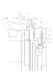
交換レンズ10は、レンズマウント11、環状弾性部材(弾性部材)12、交換レンズ本体あるいは筒部材としての外装環13、内部に少なくとも1枚のレンズが設けられているレンズ鏡筒14を有している。レンズマウント11は、前述のカメラマウント1と結合するためにレンズ側マウント当接面11a、レンズ側マウント径嵌合部11b、複数のレンズ側バヨネット爪部11c、取付面11dを有している。つまり、レンズマウント(第2マウント部)11は、複数のカメラ側バヨネット爪部1cと係合する複数のレンズ側バヨネット爪部(第2バヨネット爪部)11cを有する。取付面11dはレンズマウント11の外装環13側(筒部材側)の面である。
The
レンズマウント11とレンズ鏡筒14の位置決めと固定について説明する。レンズマウント11は、レンズ鏡筒14をスラスト方向(光軸方向)に位置決めするレンズ鏡筒当接面(取付面11d)を有している。レンズ鏡筒14には、レンズマウント11をスラスト方向に位置決めするレンズマウント当接面14aを有している。レンズ鏡筒当接面(取付面11d)をレンズマウント当接面14aに当接させた状態で、レンズマウント11を不図示のビスでレンズ鏡筒14に固定することで、レンズマウント11とレンズ鏡筒14の位置決めと固定を行うことができる。
Positioning and fixing of the
外装環13には不図示の片寄せ突起が設けられており、レンズマウント11とレンズ鏡筒14の間のレンズ鏡筒14側に寄せられて固定されている。
The
環状弾性部材12の取り付けについて説明する。環状弾性部材12は、密着部12a、把持部12b、レンズマウント側当接面12c、カメラマウント側当接面12dを有している。環状弾性部材12は、外装環13に設けられた環状弾性部材側当接面13aとレンズマウント11に挟まれている。
Attachment of the annular
この結果、環状弾性部材12の光軸方向の位置は、環状弾性部材12の把持部12bが光軸方向において、外装環13の環状弾性部材側当接面13aとレンズマウント11の取付面11dとで圧縮して挟まれることにより決まる。一方、環状弾性部材12の径方向の位置は、外装環13の内周面13bとレンズマウント11の側周面11eとで挟まれることにより決まる。より詳細には、環状弾性部材12が光軸方向において環状弾性部材側当接面13aとレンズマウント11の取付面11dとで圧縮して挟まれる結果、環状弾性部材12が径方向に広がる。そして、環状弾性部材12が径方向において内周面13bと側周面11eとで挟まれることになる。
As a result, the position of the annular
交換レンズ10の内部には複数のレンズが設けられている。複数のレンズの中にはフォーカシング時に光軸方向に移動するフォーカスレンズユニットが含まれている。ズーミング時に光軸方向に移動するズームレンズユニットが更に交換レンズ10内部に設けられていてもよい。
A plurality of lenses are provided inside the
(カメラ本体の構成)
図3に基づいてカメラ本体100の構成、特にカメラマウント1周辺の構成について説明する。
(Configuration of camera body)
The configuration of the
カメラ本体100は、カメラマウント1、バヨネット付勢用バネ2、前カバー3を有している。これらの部品は不図示のカメラ本体構造に固定されている。
The
カメラマウント1は、カメラ側マウント当接面1a、カメラ側マウント径嵌合部1b、複数のカメラ側バヨネット爪部1cを有している。交換レンズ10をカメラ本体100に装着すると、カメラ側マウント当接面1aとレンズ側マウント当接面11aが当接し、カメラ側マウント径嵌合部1bとレンズ側マウント径嵌合部11bが嵌合する。そして、カメラ側バヨネット爪部1cとレンズ側バヨネット爪部11cが当接(係合、嵌合)して、バヨネット付勢用バネ2によってレンズ側バヨネット爪部11cがカメラ本体100側に付勢される。
The
(バックフォーカスの調整方法)
バックフォーカス調整は、レンズ及びこのレンズを保持する鏡筒の部品の作製誤差によって生じる無限ピントのずれ、即ち、無限遠物体に焦点合わせをしたときの、レンズ鏡筒の所定面から焦点面までの距離の設計値からのずれを修正する作業である。
(How to adjust the back focus)
Back focus adjustment is the infinite focus deviation caused by manufacturing errors in the lens and the parts of the lens barrel that hold this lens. This is the work of correcting the deviation from the design value of the distance.
バックフォーカスの設計値からのずれ量の測定は、ピントコリメータなどの工具を用いた前述の特許文献1に記載の方法などを用いればよい。
The amount of deviation from the design value of the back focus may be measured using the method described in the above-mentioned
上記の方法で測定したバックフォーカスのずれ量と同じ量だけレンズマウント11の取付面11dを切削あるいは研磨してバックフォーカスが所定値(設計値)となるように合わせる。この作業によってバックフォーカスの調整が行われる。
The mounting
ここで、レンズマウント11の厚み(取付面11dの切削前の厚み)は以下のように設定することが好ましい。すなわち、各レンズ・鏡筒の作成誤差から生じるバックフォーカスのずれ量の最大値を計算から求める。そして、この最大値分レンズマウント11を切削あるいは研磨したとしてもレンズマウント11の厚みが実際の製品として充分に残るような値にレンズマウント11の厚みを設定することが好ましい。これにより、レンズマウント11はバックフォーカスのずれ量に関係なく必ず切削あるいは研磨されてレンズ鏡筒14に取り付けられることになる。
Here, it is preferable to set the thickness of the lens mount 11 (thickness of the mounting
なお、本実施例では、レンズマウント11の取付面11dを切削あるいは研磨する手法について述べたが、レンズ鏡筒14のレンズマウント当接面14aを切削あるいは研磨してもよい。あるいは、取付面11dとレンズマウント当接面14aの双方を切削あるいは研磨してもよい。あるいは、取付面11dとレンズマウント当接面14aの少なくも一方にバックフォーカス調整用のリング状の部材を設け、この部材を切削あるいは研磨してバックフォーカスを調整してもよい。さらに、取付面11dあるいはレンズマウント当接面14aを切削あるいは研磨しすぎてしまった場合には、取付面11dとレンズマウント当接面14aの間にワッシャーを追加してバックフォーカスを調整してもよい。
In this embodiment, the mounting
なお、本実施例における交換レンズ10はズームレンズユニットを備えたズームレンズであってもよいし、単焦点レンズであってもよい。交換レンズ10がズームレンズであっても単焦点レンズであってもバックフォーカス調整は上記の方法を用いることができる。
Note that the
(環状空隙部)
外装環13と環状弾性部材12の間には、環状空隙部(空隙部、凹部、環状凹部)15が形成されている。環状空隙部15は、環状弾性部材12のレンズマウント側当接面12cと同一平面上にあって、外装環13に環状の凹形状として形成されている。言い換えれば、外装環13には環状空隙部15が設けられている。
(Annular gap)
An annular space (space, recess, annular recess) 15 is formed between the
環状空隙部15の外径は、環状弾性部材12と外装環13の嵌め合い径と同径に形成されている。環状空隙部15の内径は、レンズマウント11の外径と同径に形成されている。環状空隙部15のスラスト方向の寸法は、前述のバックフォーカスのずれ量の最大値よりも大きく形成されている。
The outer diameter of the
(環状弾性部)
図3に基づいて環状弾性部材12について説明する。
(Annular elastic part)
The annular
交換レンズ10とカメラ100が結合される(交換レンズ10がカメラ本体100に装着される)と、環状弾性部材12の密着部12aは、前カバー3に沿うように弾性変形して前カバー3に密着する。図3においては、環状弾性部材12の弾性変形前(交換レンズ10がカメラ本体100から取り外されている状態)の形状を鎖線で示している。そして、環状弾性部材12の弾性変形後(交換レンズ10がカメラ本体100に装着されている状態)の形状を実線で示している。
When the
環状弾性部材12と前カバー3の相対的な位置関係は、前述のバックフォーカス調整におけるバックフォーカスのずれ量が0のときに、カメラマウント1とレンズマウント11の水密的結合の関係を保てるようになっている。あるいは、両者の相対的な位置関係は、前述のバックフォーカス調整におけるバックフォーカスのずれ量が0のときに、環状弾性部材12の密着部12aが変形した状態で前カバー3に接触する(密着する)ようになっている。
The relative positional relationship between the annular
前述のように、バックフォーカス調整においてレンズマウント11は、バックフォーカスのずれ量と同じ厚みだけ切削あるいは研磨される。この結果、レンズマウント11が薄くなり、環状弾性部材12と前カバー3の間隔が、バックフォーカスのずれ量、つまり、レンズマウント11の切削量(研磨量)だけ短くなる。つまり、バックフォーカス調整の結果、カメラ本体100が交換レンズ10に近づくことになる。レンズマウント11を切削あるいは研磨すると、その分だけ環状弾性部材12は更に前カバー3から押され、密着部12aと前カバー3の間に生じる摩擦が大きくなるおそれがある。
As described above, in back focus adjustment, the
つまり、環状弾性部材12が前カバー3に沿うように弾性変形する際の、弾性変形力が大きいと、環状弾性部材12と前カバー3の間に発生する摩擦力が大きくなり、交換レンズ10とカメラ本体100の着脱感が重くなるおそれがある。
That is, if the elastic deformation force generated when the annular
(本実施例によって得られる効果)
上記の摩擦増大に対する対策として、本実施例の交換レンズ10は環状空隙部15を備えている。バックフォーカスのずれ量分押された環状弾性部材12は、弾性変形をともなって、環状空隙部15に逃げることができ、上記の摩擦増大を抑制することができる。
(Effect obtained by this embodiment)
As a measure against the increase in friction, the
言い換えれば、外装環13には環状空隙部15が設けられている。そして、環状弾性部材12の一部は、アクセサリとしての交換レンズ10をカメラ本体100に装着した際に、環状空隙部15に入ることができる。このため、上記の摩擦増大を抑制し、カメラ本体に対してより着脱しやすいアクセサリを実現することができる。つまり、本実施例においては、環状弾性部材12は環状空隙部15に逃げていて、上記の摩擦増大を抑制し、交換レンズ10をカメラ本体100に快適に装着、あるいはカメラ本体100から快適に取り外すことができる。
In other words, the
環状空隙部15のスラスト方向の寸法は、前述のバックフォーカスのずれ量の最大値よりも大きいため、仮にバックフォーカスの調整量が最大値だったとしても、環状弾性部材12と環状空隙部15の間にすき間が生じることになる。つまり、バックフォーカスの調整量が最大値だったとしても、環状弾性部材12は環状空隙部15内で変形することができる。そのため、バックフォーカスのずれ量によらずに、カメラマウント1とレンズマウント11の水密的な関係性を維持することができる。
Since the dimension of the
バックフォーカスの調整量が多すぎた場合、言い換えれば、レンズマウント11の取付面11dあるいはレンズ鏡筒14のレンズマウント当接面14aを切削しすぎてしまった場合について考える。この場合には、交換レンズ10をカメラ本体100に装着した際に環状弾性部材12の一部が環状空隙部15に入ることが可能であるように交換レンズ10を構成しつつ、ワッシャーなどの調整部材でバックフォーカス調整を行ってもよい。ただし、このような調整部材を設けない方が、交換レンズ10が軽くなったり、製造コストが抑えられたりするために好ましい。
Consider the case where the amount of back focus adjustment is too large, in other words, the case where the
本実施例においては、バックフォーカス調整によって、環状弾性部材12とカバー3の間に発生する摩擦力が大きくなる事例を挙げたが、本実施例の効果はバックフォーカス調整を伴う交換レンズ10に限定されるものではない。例えば、カメラ100の前カバー3の材質が環状弾性部材12と摩擦力が大きい材質で構成される場合においても効果を発揮する。具体的には、環状弾性部材12がシリコンゴムで、前カバー3がPCなどの樹脂で構成されている場合と比較して、前カバー3がアルミニウムなどの金属であった場合、つまり前カバー3が金属部材である場合に特に有効である。
In this embodiment, the back focus adjustment increases the frictional force generated between the annular
なお、環状空隙部15は、外装環13と環状弾性部材12の間に完全に挟まれている閉じた空間である必要はない。例えば、図2に示すように、環状弾性部材12を組み立てる際の空気逃げとして、環状空隙部15の底面と交換レンズ10の内部あるいは外部をつなぐように外装環13を貫通する貫通部15aを外装環13に設けてもよい。
Note that the
また、環状空隙部15の内径はレンズマウント11の外径と同径に形成しているが、環状空隙部15の内径をレンズマウント11の外径よりも大きくしてもよい。つまり、環状空隙部15の内径はレンズマウント11の外径以上であればよい。
Also, although the inner diameter of the
また、環状空隙部15の外径は環状弾性部材12と外装環13の嵌め合い径と同径に形成されているが、環状空隙部15の外径を環状弾性部材12と外装環13の嵌め合い径よりも小さくしてもよい。つまり、環状空隙部15の外径は環状弾性部材12と外装環13の嵌め合い径以下であればよい。
The outer diameter of the
なお、環状空隙部15の外径が環状弾性部材12の外径よりも小さい場合には、環状弾性部材12が環状空隙部15に対して圧入され、環状弾性部材12を安定して保持することができる。
When the outer diameter of the
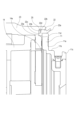
[第2実施例]
図4及び図5を用いて第2実施例におけるアクセサリについて説明する。前述の第1実施例と本実施例との違いは外装環が備える環状空隙部の形状(あるいは大きさ)及び環状弾性部材の形状である。その他同一の部分については同一の符号を付して説明を省略する。
[Second embodiment]
An accessory in the second embodiment will be described with reference to FIGS. 4 and 5. FIG. The difference between the first embodiment described above and the present embodiment is the shape (or size) of the annular gap provided in the exterior ring and the shape of the annular elastic member. Other same parts are denoted by the same reference numerals, and descriptions thereof are omitted.
前述の第1実施例においては、図2及び図3に示すように、外装環13が備える環状空隙部15の光軸直交方向の幅(紙面上下方向の幅)は、環状弾性部材12の光軸直交方向の幅よりも小さい。そして、図2に示すように、交換レンズ10がカメラ本体100から取り外されている際には環状空隙部15の底面から環状弾性部材12は離れている。そして、図3に示すように、交換レンズ10をカメラ本体100に装着した際に環状空隙部15の底面に環状弾性部材12が接触する。
In the above-described first embodiment, as shown in FIGS. 2 and 3, the width of the
このような第1実施例に対して、本実施例におけるアクセサリである交換レンズ20は、外装環13の代わりに外装環23、環状弾性部材12の代わりに環状弾性部材22、環状空隙部15の代わりに環状空隙部25を備えている。交換レンズ20は交換レンズ10と同様のレンズマウント11を備えているために、カメラ本体100に対して着脱可能である。
In contrast to the first embodiment described above, the interchangeable lens 20 as an accessory in this embodiment includes an
図4及び図5に示すように、環状空隙部25の光軸直交方向の幅は環状弾性部材22の光軸直交方向の幅と同じである。そして、図4に示すように、交換レンズ20がカメラ本体100から取り外されている際には、環状空隙部25の底面に環状弾性部材22の一部(第1部分)22bが接触している。より詳細には、交換レンズ20がカメラ本体100から取り外されている際には、環状弾性部材22の当接面22cが、環状空隙部25の底面の一部である外装環23の弾性部材当接面23aに接触している。
As shown in FIGS. 4 and 5, the width of the
そして、図5に示すように、交換レンズ20がカメラ本体100に装着されている際には、環状空隙部25の底面に環状弾性部材22の一部(第1部分)22bに加えて、環状弾性部材22の一部(第2部分)22dも接触する。より詳細には、交換レンズ20がカメラ本体100に装着されている際には、当接面22cが当接面23aに当接する。そして、環状弾性部材22の当接面22dが、環状空隙部25の底面の一部である外装環23の弾性部材当接面23bに接触している。
As shown in FIG. 5, when the interchangeable lens 20 is attached to the
なお、交換レンズ20がカメラ本体100から取り外されている際には、当接面22cが当接面23aに必ず接触しなければいけないわけではない。さらに、交換レンズ20がカメラ本体100に装着されている際に、当接面22dが当接面23bに必ず接触しなければいけないわけではない。交換レンズ20がカメラ本体100から取り外されている際の光軸方向における当接面22dと当接面23bの間の距離が、当接面22cと当接面23aの間の距離よりも大きければよい。言い換えれば、交換レンズ20がカメラ本体100に装着する際に環状弾性部材22が変形した部分が逃げるスペースが環状空隙部25の中にあればよい。
Note that when the interchangeable lens 20 is detached from the
このような構成の本実施例においても、前述の第1実施例と同様に、カメラ本体に対してより着脱しやすいアクセサリを実現することができる。 Also in this embodiment having such a configuration, it is possible to realize an accessory that is easier to attach to and detach from the camera body, as in the first embodiment.
[変形例]
前述の第1及び第2実施例においてはアクセサリとして交換レンズを例示したが、本発明は交換レンズに限定されるものではない。カメラ本体100に装着可能で、かつ、環状空隙部、環状弾性部材、レンズマウント11と同じ構造のマウント部を有し、交換レンズとカメラ本体100との間に装着可能なアダプタに前述の第1及び第2実施例の構造を適用してもよい。ここでいうアダプタはエクステンダーやマウント変換アダプタなどのことである。
[Modification]
In the first and second embodiments described above, the interchangeable lens was exemplified as an accessory, but the present invention is not limited to the interchangeable lens. The adapter that can be attached to the
また、環状弾性部材の代わりに環状ではない弾性部材を用いてもよい。例えば、円環状、言い換えれば、360度つながっている一つの弾性部材の代わりに、所定の間隔を空けて同一円周上に配置した複数の弾性部材を用いてもよい。これに合わせて環状空隙部の代わりに、所定の間隔を空けて同一円周上に配置した複数の空隙部を用いてもよい。 Also, instead of the annular elastic member, a non-annular elastic member may be used. For example, instead of an annular ring, in other words, one elastic member connected 360 degrees, a plurality of elastic members arranged on the same circumference at predetermined intervals may be used. Accordingly, instead of the annular gap, a plurality of gaps arranged on the same circumference at predetermined intervals may be used.
また、前述の第1及び第2実施例においては交換レンズ本体あるいは筒部材としての外装環13に空隙部を設けた構成を例示したが、本発明はこのような構成に限定されるものではない。筒部材、言い換えれば筒状の部材あるいは円環状の部材であれば、外装環13以外の例えばレンズ鏡筒14などの部材に空隙部を設けても良い。
In addition, in the first and second embodiments described above, the structure in which the
10 交換レンズ(アクセサリ)
11 レンズマウント(第2マウント部)
11c レンズ側バヨネット爪部(第2バヨネット爪部)
12 環状弾性部材(弾性部材)
13 外装環(筒部材)
15 環状空隙部(凹部)
10 Interchangeable lens (accessory)
11 lens mount (second mount section)
11c Lens-side bayonet claw (second bayonet claw)
12 Annular elastic member (elastic member)
13 exterior ring (cylindrical member)
15 annular gap (recess)
Claims (15)
前記アクセサリを前記カメラ本体に装着した際に前記第1マウント部と係合する第2マウント部と、
前記アクセサリを前記カメラ本体に装着した際に前記カメラ本体と接触する弾性部材と、
前記弾性部材を保持する筒部材を有し、
前記筒部材は、前記弾性部材に対して前記カメラ本体とは反対側に設けられた凹部を備え、
前記凹部は、前記アクセサリが前記カメラ本体から取り外された状態で前記弾性部材との間に空隙を形成し、前記アクセサリを前記カメラ本体に装着した際に前記弾性部材の一部が前記空隙に入ることが可能であることを特徴とするアクセサリ。 An accessory detachable from a camera body having a first mount,
a second mount portion that engages with the first mount portion when the accessory is attached to the camera body;
an elastic member that contacts the camera body when the accessory is attached to the camera body;
Having a cylindrical member that holds the elastic member,
the cylindrical member has a recess provided on the side opposite to the camera body with respect to the elastic member,
The recess forms a gap with the elastic member when the accessory is detached from the camera body, and part of the elastic member enters the gap when the accessory is attached to the camera body. An accessory characterized in that it is capable of
前記アクセサリを前記カメラ本体に装着した際に前記凹部の底面に前記第1部分及び前記第2部分が接触することを特徴とする請求項7に記載のアクセサリ。 the second portion of the elastic member is separated from the bottom surface of the recess when the accessory is removed from the camera body;
8. An accessory according to claim 7, wherein said first portion and said second portion come into contact with the bottom surface of said recess when said accessory is attached to said camera body.
請求項12に記載のアクセサリを備えることを特徴とする撮像装置。 the camera body;
An imaging device comprising the accessory according to claim 12 .
前記レンズ装置と、
請求項13に記載のアクセサリを備えることを特徴とする撮像装置。 the camera body;
the lens device;
An imaging device comprising the accessory according to claim 13 .
Priority Applications (3)
| Application Number | Priority Date | Filing Date | Title |
|---|---|---|---|
| JP2018151367A JP7224807B2 (en) | 2018-08-10 | 2018-08-10 | Accessory and imaging device equipped with the same |
| US16/528,399 US11327388B2 (en) | 2018-08-10 | 2019-07-31 | Accessory and imaging apparatus including the same |
| CN201910719215.1A CN110824815B (en) | 2018-08-10 | 2019-08-06 | Accessory and image forming apparatus including the same |
Applications Claiming Priority (1)
| Application Number | Priority Date | Filing Date | Title |
|---|---|---|---|
| JP2018151367A JP7224807B2 (en) | 2018-08-10 | 2018-08-10 | Accessory and imaging device equipped with the same |
Publications (3)
| Publication Number | Publication Date |
|---|---|
| JP2020027162A JP2020027162A (en) | 2020-02-20 |
| JP2020027162A5 JP2020027162A5 (en) | 2021-09-09 |
| JP7224807B2 true JP7224807B2 (en) | 2023-02-20 |
Family
ID=69407009
Family Applications (1)
| Application Number | Title | Priority Date | Filing Date |
|---|---|---|---|
| JP2018151367A Active JP7224807B2 (en) | 2018-08-10 | 2018-08-10 | Accessory and imaging device equipped with the same |
Country Status (3)
| Country | Link |
|---|---|
| US (1) | US11327388B2 (en) |
| JP (1) | JP7224807B2 (en) |
| CN (1) | CN110824815B (en) |
Citations (2)
| Publication number | Priority date | Publication date | Assignee | Title |
|---|---|---|---|---|
| JP2004101725A (en) | 2002-09-06 | 2004-04-02 | Canon Inc | Lens arrangement and photographic device |
| JP2009300926A (en) | 2008-06-17 | 2009-12-24 | Sigma Corp | Camera accessory and camera system |
Family Cites Families (25)
| Publication number | Priority date | Publication date | Assignee | Title |
|---|---|---|---|---|
| JPS4636740B1 (en) * | 1968-04-06 | 1971-10-28 | ||
| JPS5937782Y2 (en) * | 1978-02-16 | 1984-10-19 | 富士写真フイルム株式会社 | Sealed structure of waterproof camera |
| US4963902A (en) | 1988-01-19 | 1990-10-16 | Canon Kabushiki Kaisha | Camera system |
| JP2864384B2 (en) | 1989-07-10 | 1999-03-03 | 株式会社ニコン | Mounting mechanism for camera and its interchangeable lens |
| JPH0453232U (en) * | 1990-09-10 | 1992-05-07 | ||
| JPH07128718A (en) | 1993-10-29 | 1995-05-19 | Olympus Optical Co Ltd | Mount mechanism for camera |
| US5713048A (en) | 1994-05-24 | 1998-01-27 | Asahi Kogaku Kogyo Kabushiki Kaisha | Waterproof and/or water-resistant camera |
| US5946501A (en) | 1994-05-24 | 1999-08-31 | Asahi Kogaku Kogyo Kabushiki Kaisha | Waterproof and/or water-resistant camera |
| JP3411670B2 (en) | 1994-05-24 | 2003-06-03 | ペンタックス株式会社 | Waterproof structure of drip-proof camera and open / close lid |
| JPH08106121A (en) | 1994-10-06 | 1996-04-23 | Asahi Optical Co Ltd | Waterproof structure |
| US5734935A (en) * | 1995-10-13 | 1998-03-31 | Nikon Corporation | Camera system and intermediate adapter |
| CN1244014C (en) | 1995-10-13 | 2006-03-01 | 株式会社尼康 | Camera system and intermediate adapter |
| JPH10186486A (en) | 1996-12-25 | 1998-07-14 | Canon Inc | Camera |
| JP3728080B2 (en) | 1997-12-17 | 2005-12-21 | キヤノン株式会社 | Cameras, camera accessories and camera systems |
| JP3835500B2 (en) * | 1998-03-16 | 2006-10-18 | 富士写真フイルム株式会社 | Waterproof structure of the camera |
| JP2001042407A (en) | 1999-07-28 | 2001-02-16 | Olympus Optical Co Ltd | Sealing device for camera |
| JP4636740B2 (en) | 2001-07-02 | 2011-02-23 | キヤノン株式会社 | Interchangeable lens and camera system having the same |
| JP3513512B1 (en) | 2003-08-01 | 2004-03-31 | キヤノン株式会社 | Interchangeable lens, interchangeable lens system and camera system |
| JP2009300928A (en) | 2008-06-17 | 2009-12-24 | Sigma Corp | Camera accessory and camera system |
| JP5445479B2 (en) | 2011-01-28 | 2014-03-19 | 株式会社ニコン | Camera accessories, accessory side mount, camera body and body side mount |
| JP2013080078A (en) | 2011-10-04 | 2013-05-02 | Canon Inc | Lens barrel |
| JP6284410B2 (en) | 2014-04-11 | 2018-02-28 | 東洋ゴム工業株式会社 | Stabilizer bush |
| CN204178095U (en) | 2014-10-27 | 2015-02-25 | 深圳市大疆创新科技有限公司 | The fuselage of camera lens limit assembly, camera and camera model |
| JP2016224219A (en) | 2015-05-29 | 2016-12-28 | 東芝テリー株式会社 | Camera dust-proof construction |
| JP6838928B2 (en) | 2016-10-18 | 2021-03-03 | キヤノン株式会社 | Imaging device and mount adapter |
-
2018
- 2018-08-10 JP JP2018151367A patent/JP7224807B2/en active Active
-
2019
- 2019-07-31 US US16/528,399 patent/US11327388B2/en active Active
- 2019-08-06 CN CN201910719215.1A patent/CN110824815B/en active Active
Patent Citations (2)
| Publication number | Priority date | Publication date | Assignee | Title |
|---|---|---|---|---|
| JP2004101725A (en) | 2002-09-06 | 2004-04-02 | Canon Inc | Lens arrangement and photographic device |
| JP2009300926A (en) | 2008-06-17 | 2009-12-24 | Sigma Corp | Camera accessory and camera system |
Also Published As
| Publication number | Publication date |
|---|---|
| CN110824815A (en) | 2020-02-21 |
| US11327388B2 (en) | 2022-05-10 |
| JP2020027162A (en) | 2020-02-20 |
| CN110824815B (en) | 2022-04-19 |
| US20200050088A1 (en) | 2020-02-13 |
Similar Documents
| Publication | Publication Date | Title |
|---|---|---|
| US20200225563A1 (en) | Accessory, image pickup apparatus on which same is mountable, and camera system | |
| JP2006343510A (en) | Lens adapter | |
| EP2428829B1 (en) | Interchangeable lens device | |
| US11143841B2 (en) | Accessory, image pickup apparatus on which same is mountable, and camera system | |
| JP6788354B2 (en) | Lens accessories, lens devices, and imaging devices | |
| JP7224807B2 (en) | Accessory and imaging device equipped with the same | |
| US11237355B2 (en) | Lens unit, camera system, and elastic member | |
| JP7277185B2 (en) | Lens device that can be attached with an intermediate adapter | |
| JP7062515B2 (en) | Mounting device and imaging device | |
| JP2005338415A (en) | Camera lens mirror frame device | |
| CN111295610A (en) | Lens unit | |
| JP2009300926A (en) | Camera accessory and camera system | |
| JPH10186486A (en) | Camera | |
| JP2009300928A (en) | Camera accessory and camera system | |
| JP2018072465A (en) | Lens adapter | |
| JP7207892B2 (en) | LENS DEVICE AND IMAGING DEVICE INCLUDING THE SAME | |
| JP5448990B2 (en) | Lens unit accessory attachment / detachment mechanism | |
| JP2020012881A (en) | Imaging device and mount device | |
| JP7139606B2 (en) | interchangeable lens | |
| JP2018072547A (en) | Lens adapter and imaging apparatus | |
| JP2009086044A (en) | Mount structure | |
| JP2009300927A (en) | Camera accessory and camera system | |
| JP5159334B2 (en) | Lens cap | |
| US10372019B2 (en) | Lens driving adapter, lens apparatus and image capturing apparatus | |
| JP2021148869A (en) | Fixing device and imaging apparatus |
Legal Events
| Date | Code | Title | Description |
|---|---|---|---|
| A521 | Request for written amendment filed |
Free format text: JAPANESE INTERMEDIATE CODE: A523 Effective date: 20210729 |
|
| A621 | Written request for application examination |
Free format text: JAPANESE INTERMEDIATE CODE: A621 Effective date: 20210729 |
|
| A977 | Report on retrieval |
Free format text: JAPANESE INTERMEDIATE CODE: A971007 Effective date: 20220629 |
|
| A131 | Notification of reasons for refusal |
Free format text: JAPANESE INTERMEDIATE CODE: A131 Effective date: 20220719 |
|
| A521 | Request for written amendment filed |
Free format text: JAPANESE INTERMEDIATE CODE: A523 Effective date: 20220916 |
|
| TRDD | Decision of grant or rejection written | ||
| A01 | Written decision to grant a patent or to grant a registration (utility model) |
Free format text: JAPANESE INTERMEDIATE CODE: A01 Effective date: 20230110 |
|
| A61 | First payment of annual fees (during grant procedure) |
Free format text: JAPANESE INTERMEDIATE CODE: A61 Effective date: 20230208 |
|
| R151 | Written notification of patent or utility model registration |
Ref document number: 7224807 Country of ref document: JP Free format text: JAPANESE INTERMEDIATE CODE: R151 |