JP7215460B2 - Map system, map generation program, storage medium, vehicle device and server - Google Patents
Map system, map generation program, storage medium, vehicle device and server Download PDFInfo
- Publication number
- JP7215460B2 JP7215460B2 JP2020089651A JP2020089651A JP7215460B2 JP 7215460 B2 JP7215460 B2 JP 7215460B2 JP 2020089651 A JP2020089651 A JP 2020089651A JP 2020089651 A JP2020089651 A JP 2020089651A JP 7215460 B2 JP7215460 B2 JP 7215460B2
- Authority
- JP
- Japan
- Prior art keywords
- data
- vehicle
- map
- reliability
- image
- Prior art date
- Legal status (The legal status is an assumption and is not a legal conclusion. Google has not performed a legal analysis and makes no representation as to the accuracy of the status listed.)
- Active
Links
Images


Landscapes
- Instructional Devices (AREA)
- Navigation (AREA)
- Traffic Control Systems (AREA)
Description
本発明は、地図を生成する地図システム、地図生成プログラム、記憶媒体、車両用装置およびサーバに関する。 The present invention relates to a map system, a map generation program, a storage medium, a vehicle device, and a server for generating maps.
特許文献1には、車両に搭載されたカメラにより撮像された画像を用いてランドマークなどの位置情報を記録し、それら情報をサーバなどにアップロードして疎な地図を生成し、車両の走行時には生成された疎な地図をダウンロードして自車両の位置を決定するシステムに関する技術が開示されている。 In Patent Document 1, an image captured by a camera mounted on a vehicle is used to record location information such as landmarks, and the information is uploaded to a server or the like to generate a sparse map. A technology related to a system that determines the position of the own vehicle by downloading a generated sparse map is disclosed.
上述したようなシステムにおいて、サーバにアップロードするためのデータであるプローブデータは、同じ箇所を対象としたデータであっても、それを生成した車両に搭載されたカメラなどの撮像装置の仕様、取付位置、姿勢などにより互いに異なるものとなることがある。従来、サーバは、このようなプローブデータを全て統合することで地図を生成する。そのため、プローブデータのデータ数が増えるほど、サーバでの地図の生成精度が向上する。 In the system described above, the probe data, which is the data to be uploaded to the server, is the data for the same location, but the specifications and installation of the imaging device such as the camera mounted on the vehicle that generated it. They may be different from each other depending on the position, posture, and the like. Conventionally, a server generates a map by aggregating all such probe data. Therefore, as the number of data in the probe data increases, the map generation accuracy in the server improves.
しかし、プローブデータのデータ数が少ない場合、それらプローブデータに偏りが生じていると、サーバにおいて地図を生成する際の精度を向上することができないおそれがある。つまり、従来技術では、プローブデータのデータ数が少ない場合には、サーバでの地図の生成精度が低下する可能性があった。 However, when the number of probe data is small and the probe data is biased, there is a possibility that the server cannot improve the accuracy of map generation. In other words, in the conventional technology, when the number of probe data is small, there is a possibility that the accuracy of map generation by the server will be lowered.
本発明は上記事情に鑑みてなされたものであり、その目的は、サーバでの地図の生成精度を高めることができる地図システム、地図生成プログラム、記憶媒体、車両用装置およびサーバを提供することにある。 SUMMARY OF THE INVENTION The present invention has been made in view of the above circumstances, and its object is to provide a map system, a map generation program, a storage medium, a vehicle device, and a server that can improve the accuracy of map generation in a server. be.
請求項1に記載の地図システムは、車両に搭載され車両の周辺の画像を撮像する撮像装置を備えた車両用装置と、車両用装置から送信される撮像装置により撮像された画像から抽出される特徴点に対応するデータを用いて地図を生成するサーバと、を備えたシステムである。地図システムは、複数の車両用装置から送信されるデータの偏りに基づいてデータに重み付けを行い、その重み付けに基づいて複数のデータの少なくとも一部を統合して地図を生成する統合部を備える。前記統合部は、前記データに対応する画像を用いるとともにStructure From Motionの手法を利用して前記車両の挙動である自車挙動を推定する際における推定精度が相対的に高いと判断される前記データの優先度を前記推定精度が相対的に低いと判断される前記データの優先度に比べて高くするように前記データの重み付けを行う。 The map system according to claim 1 is extracted from a vehicle device equipped with an image capturing device mounted on a vehicle and capturing an image of the surroundings of the vehicle, and an image captured by the image capturing device transmitted from the vehicle device. and a server that generates a map using data corresponding to the feature points. The map system includes an integration unit that weights data based on the bias of data transmitted from a plurality of vehicle devices, integrates at least a portion of the plurality of data based on the weighting, and generates a map. The integration unit uses the image corresponding to the data and uses the structure-from-motion technique to estimate the behavior of the own vehicle, which is the behavior of the vehicle. The data are weighted so that the priority of the data is higher than the priority of the data determined to have relatively low estimation accuracy.
上記構成によれば、複数の車両用装置からサーバに送信されるデータ、つまりプローブデータに偏りがある場合でも、その偏りに基づいてデータに重み付けが行われ、その重み付けを考慮して地図が生成される。このような構成によれば、従来に比べ、車両用装置からサーバに送信されるデータの数が少なくとも、サーバは、より精度の高い地図を生成することができる。したがって、上記構成によれば、サーバでの地図の生成精度を高めることができるという優れた効果が得られる。 According to the above configuration, even if data transmitted from a plurality of vehicle devices to the server, that is, probe data, is biased, the data is weighted based on the bias, and a map is generated in consideration of the weighting. be done. According to such a configuration, the server can generate a more accurate map than the conventional one, even if the number of data transmitted from the vehicle device to the server is at least. Therefore, according to the above configuration, it is possible to obtain an excellent effect of increasing the accuracy of map generation in the server.
以下、複数の実施形態について図面を参照して説明する。なお、各実施形態において実質的に同一の構成には同一の符号を付して説明を省略する。
(第1実施形態)
以下、第1実施形態について図1~図5を参照して説明する。
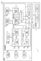
図1に示す地図システム1は、自律的ナビゲーションのための地図システムである。地図システム1は、GPSなどの自車両の位置を特定する従来の機能に対して、追加的に機能してより高精度に位置の特定をすることに効果を発揮する。地図システム1は、大きく分けて、地図活用および地図更新の2つの機能を備えている。
A plurality of embodiments will be described below with reference to the drawings. In addition, the same code|symbol is attached|subjected to the substantially same structure in each embodiment, and description is abbreviate|omitted.
(First embodiment)
A first embodiment will be described below with reference to FIGS. 1 to 5. FIG.
The map system 1 shown in FIG. 1 is a map system for autonomous navigation. The map system 1 functions additionally to the conventional function of specifying the position of the own vehicle such as GPS, and is effective in specifying the position with higher accuracy. The map system 1 has two main functions: map utilization and map update.
地図活用においては、サーバ2に格納された地図情報が車両にダウンロードされ、車両はダウンロードされた地図情報と、例えばカメラなどの画像センサ3により撮像された画像に含まれる標識などのランドマークの位置とに基づいて自車両の位置を特定する。本明細書では、サーバ2に格納された地図情報のことを統合地図と称することがある。この場合、特定した自車両の現在位置に基づいて、車両制御部4が車両に搭載されたハードウェアを動作させるためのアクチュエータに対して対応する命令を出力することで運転支援が実現される。アクチュエータとは、例えばブレーキ、スロットル、ステアリング、ランプなど、車両をハードウェア的に制御するための装置である。
In map utilization, the map information stored in the
一方、地図更新においては、車両に搭載された画像センサ3、車速センサ5、図示しないミリ波センサなどの各種センサにより得られた情報がプローブデータとしてサーバ2にアップロードされ、サーバ2内の統合地図が逐次更新される。これにより、車両は、常に最新の地図情報に基づいて高精度に位置特定がされつつ、例えば運転支援や自動ステアリングが実現される。
On the other hand, in updating the map, information obtained by various sensors such as the image sensor 3, the vehicle speed sensor 5, and a millimeter wave sensor (not shown) mounted on the vehicle is uploaded to the
地図システム1において、ヒューマンマシンインターフェース6は、各種の情報をユーザに通知したり、ユーザが所定の操作を車両に伝達したりするためのユーザインタフェースである。なお、本明細書では、ヒューマンマシンインターフェースのことをHMIと省略することがある。HMI6には、例えばカーナビゲーション装置に付属するディスプレイ、インストルメントパネルに内蔵されたディスプレイ、ウィンドシールドに投影されるヘッドアップディスプレイ、マイク、スピーカなどが含まれる。さらには、車両と通信可能に接続されたスマートフォンなどのモバイル端末も地図システム1内のHMI6になり得る。
In the map system 1, the human-
ユーザはHMI6に表示される情報を視覚的に得るほか、音声や警告音、振動によっても情報を得ることができる。また、ユーザは、ディスプレイのタッチ操作や音声により車両に対して所望の動作を要求することができる。例えば、ユーザが地図情報を活用して自動ステアリングなどの高度運転支援のサービスを受けようとするとき、ユーザはHMI6を介して該機能を有効化する。例えば、ディスプレイ上に示された「地図連携」ボタンをタップすると地図活用の機能が有効化され、地図情報のダウンロードが開始される。
In addition to visually obtaining the information displayed on the
別の例では、音声にて命令を与えることにより地図活用の機能が有効化される。なお、地図更新に係る地図情報のアップロードについては、車両とサーバ2との通信が確立されている間常時実行されていてもよいし、「地図連携」ボタンをタップして地図活用の機能が有効化されている間に実行されるようにされてもよいし、ユーザの意思を反映する別のUIによって有効化されてもよい。
In another example, a map-based feature is activated by giving a voice command. It should be noted that uploading of map information related to map updating may be performed constantly while communication between the vehicle and the
本実施形態の地図システム1は、サーバ2および車両側の各構成を備える。車両側の各構成とは、画像センサ3、車両制御部4、車速センサ5、HMI6、GPS受信部7および制御装置8などである。これら車両側の各構成のうち、画像センサ3および制御装置8は、画像センサ3により撮像された画像に対応するデータをサーバ2に送信する車両用装置9として機能する。
The map system 1 of this embodiment includes a
サーバ2は、車両用装置9などが搭載される車両から隔離した箇所に設けられている。サーバ2は、車両用装置9から送信される画像センサ3により撮像された画像に対応するデータを用いて地図を生成するもので、制御装置10を備えている。制御装置10は、CPU、ROM、RAMおよびI/Oなどを有するマイクロコンピュータを主体として構成されており、統合部11および更新部12を備える。
The
これら各機能ブロックは、制御装置10のCPUが非遷移的実体的記憶媒体に格納されているコンピュータプログラムを実行することでコンピュータプログラムに対応する処理を実行することにより実現されている、つまりソフトウェアにより実現されている。したがって、制御装置10のマイクロコンピュータが実行するコンピュータプログラムには、地図生成および地図更新に関連する各処理の少なくとも一部を実行するためのプログラム、つまり地図生成プログラムの少なくとも一部が含まれている。統合部11および更新部12は、前述した地図更新に関する各種の処理を実行するためのものであり、それらの詳細については後述する。
Each of these functional blocks is implemented by the CPU of the
GPS受信部7は、図示しないGPSアンテナを介して受信した信号により表されるGPS情報を表すデータDaを制御装置8などへと出力する。車速センサ5は、車両の速度である車速を検出するものであり、車両が有する車輪の速度を検出する車輪速センサとして構成されている。車速センサ5は、その検出値である検出速度を表す信号Saを制御装置8などへと出力する。
The
画像センサ3は、車両に搭載され、車両周辺の環境、具体的には車両の進行方向前方における所定範囲の環境を撮像する撮像装置である。なお、画像センサ3は、車両の進行方向前方を撮像するものに限らずともよく、例えば後方、側方を撮像するものでもよい。画像センサ3により撮像された車両周辺の環境の情報は、静止画または動画(以下、これらを総称して画像と称する)の形式で図示しないメモリに格納される。制御装置8は、そのメモリに格納されたデータDbを読み出し可能に構成されており、そのデータDbに基づいて各種処理を実行する。
The image sensor 3 is mounted on a vehicle and is an imaging device that captures an image of the environment around the vehicle, specifically, the environment in a predetermined range in front of the vehicle in the direction of travel. Note that the image sensor 3 is not limited to imaging the front in the direction of travel of the vehicle, and may, for example, image the rear or side. Information about the environment around the vehicle captured by the image sensor 3 is stored in a memory (not shown) in the form of still images or moving images (hereinafter collectively referred to as images). The
制御装置8は、CPU、ROM、RAMおよびI/Oなどを有するマイクロコンピュータを主体として構成されている。制御装置8は、スケールファクタ補正部13、エゴモーション算出部14、ランドマーク検出部15、地図生成部16、ローカライズ部17などの機能ブロックを備える。これら各機能ブロックは、制御装置8のCPUが非遷移的実体的記憶媒体に格納されているコンピュータプログラムを実行することでコンピュータプログラムに対応する処理を実行することにより実現されている、つまりソフトウェアにより実現されている。
The
制御装置8は、車両に搭載された電子制御装置、つまりECUなどの車載器の一部を構成している。制御装置8のマイクロコンピュータが実行するコンピュータプログラムには、地図生成および地図更新に関連する各処理の少なくとも一部を実行するためのプログラム、つまり地図生成プログラムの少なくとも一部が含まれている。スケールファクタ補正部13は、車速センサ5から与えられる信号Saおよび画像センサ3により撮像された画像を表すデータDbに基づいて、車速センサ5のスケールファクタを学習する。
The
なお、本明細書では、スケールファクタ補正部のことをSF補正部と省略することがある。車速センサ5のスケールファクタとは、車速センサ5の測定対象である車速に対する車速センサ5の検出値の比、つまり車速センサ5の入力変化に対する出力変化の比のことであり、車速センサ5の検出値から車速の真値を求めるための係数である。SF補正部13は、車速センサ5から与えられる信号Saと学習により補正されたスケールファクタとに基づいて自車両の車速を検出し、その検出値を表すデータDcをエゴモーション算出部14へと出力する。
In this specification, the scale factor corrector may be abbreviated as the SF corrector. The scale factor of the vehicle speed sensor 5 is the ratio of the detected value of the vehicle speed sensor 5 to the vehicle speed to be measured by the vehicle speed sensor 5, that is, the ratio of the output change to the input change of the vehicle speed sensor 5. This is a coefficient for obtaining the true value of the vehicle speed from the value. The
エゴモーション算出部14は、画像センサ3により撮像された画像に基づいて車両の挙動である自車挙動を推定する。この場合、エゴモーション算出部14は、Structure From Motionの手法を利用して自車挙動を推定する構成となっている。なお、本明細書では、Structure From MotionのことをSFMと省略することがある。エゴモーション算出部14は、SFMモジュールにより構成されるSFM認識部18および走行軌跡生成部19を備えている。
The
SFM認識部18は、データDbに基づいて、自車挙動、つまり車両自身の姿勢を表すパラメータであるエゴモーションの推定などを行う。なお、エゴモーションには、ヨー、ロール、ピッチおよび並進移動を示す情報が含まれる。上記構成では、画像センサ3は、車両の走行に伴い、移動しながら車両の周辺画像を撮像することになる。SFM認識部18は、画像センサ3が移動しながら撮像した2視点の画像、つまり1つの画像センサ3により異なるタイミングで撮像された撮像位置の異なる2つのフレーム分の画像において、コーナーやエッジなどの対応がとり易い特徴点を抽出する。
Based on the data Db, the
SFM認識部18は、2つのフレーム分の画像において抽出した特徴点を対応付け、それらの位置関係に基づいて特徴点のオプティカルフローを算出する。SFM認識部18は、算出した複数のオプティカルフローを手掛かりに、各特徴点の三次元位置と、画像センサ3の姿勢、つまりエゴモーションを推定する。なお、SFM認識部18は、このような手法により自車両の移動量を知ることができるが、そのスケールの精度に課題がある。そこで、SFM認識部18は、GPS情報を表すデータDaおよび車速の検出値を表すデータDcに基づいて自車両の移動速度を取得し、その移動速度に基づいて上記スケールの精度を向上させるようになっている。
The
SFM認識部18は、推定したエゴモーションを表すデータDdを、走行軌跡生成部19およびランドマーク検出部15へと出力する。走行軌跡生成部19は、SFM認識部18により推定されるエゴモーションを毎時積算し、自車両がどのように移動したのかを表す走行軌跡を生成する。走行軌跡生成部19は、生成した走行軌跡を表すデータDeを地図生成部16へと出力する。
The
ランドマーク検出部15は、認識部20および物標生成部21を備えている。認識部20は、データDbに基づいて、画像センサ3により撮像された画像上におけるランドマークの位置を検出する。なお、ランドマークの位置の検出手法としては、様々な手法を採用することができる。上記ランドマークには、例えば標識、看板、電柱や街灯などのポール、白線、信号機などが含まれる。
The
また、認識部20は、データDbに基づいて、自車両の走路を認識して道路パラメータおよび区画線を表す情報である区画線情報を取得する。道路パラメータには、車線の幅であるレーン幅、車線すなわち道路の曲率などの車線の形状を表す情報が含まれる。また、道路パラメータには、車線の幅方向中央位置から自車両の位置までの距離を表すオフセット、車線すなわち道路の接線方向と自車両の進行方向とのなす角度を表すヨー角などの車線の形状に対する自車両の走行状態を表す情報も含まれる。
Based on the data Db, the
この場合、上述した区画線情報などの走路情報も上記ランドマークに含まれる。認識部20は、このようなランドマークの検出結果を表すデータDfを物標生成部21へと出力する。物標生成部21は、認識部20から与えられるデータDfと、SFM認識部18から与えられるデータDdと、に基づいて、検出されたランドマークとその中のSFMの点を照合し、これにより、ランドマークの距離、横位置を含めた物理位置情報を求める。ランドマーク検出部15は、認識部20により取得された道路パラメータを表すデータDgを車両制御部4へと出力する。また、ランドマーク検出部15は、物標生成部21により生成された区画線情報などの走路情報も含まれたランドマークの位置に関する情報を表すデータDhを地図生成部16へと出力する。
In this case, the landmarks also include track information such as the lane marking information described above. The
地図生成部16は、GPS情報を表すデータDa、エゴモーション算出部14から与えられるデータDeおよびランドマーク検出部15から与えられるデータDhに基づいて地図情報を生成する。具体的には、地図生成部16は、GPS情報、生成されたランドマークおよび走行軌跡を紐付け、それにより断片的な地図データである地図情報を生成する。本明細書では、地図生成部16により生成される地図情報のことをプローブ地図と称することがある。
The
地図生成部16により生成されたプローブ地図を表すデータDiは、プローブデータとしてサーバ2にアップロードされるとともに、ローカライズ部17へと出力される。なお、この場合、地図生成部16により生成されるデータDiには、画像センサ3の車両への搭載位置、画像センサ3の車両への搭載姿勢および画像センサ3の解像度、画角などの仕様を表す情報も含まれている。
The data Di representing the probe map generated by the
プローブ地図は、SFMの精度に限界があることなどから、その精度は十分に高いとは言い難い。そこで、サーバ2の統合部11は、詳細は後述するが、各車両の車載器から送信されるデータDiに基づいて、複数のプローブ地図を重ね合わせて統合し、地図の精度を向上させる。サーバ2の更新部12は、統合部11による統合が成功すると、統合地図を更新する。サーバ2は、統合地図を表すデータDjを各車両の車載器へと配信する。この場合、サーバ2は、配信先の車両の概略位置をGPS情報などに基づいて特定し、その概略位置の周辺(例えば概略位置を中心とした半径数kmの範囲)の統合地図を配信する。なお、車載器側に地図が存在する場合、その地図との差分配信も可能である。
It is difficult to say that the accuracy of the probe map is sufficiently high, because the accuracy of SFM is limited. Therefore, the
ローカライズ部17は、自車両の現在位置を推定するローカライズを実行する。ローカライズ部17は、サーバ2から統合地図を表すデータDjをダウンロードし、そのダウンロードしたデータDjと、プローブ地図を表すデータDiおよび画像センサ3により撮像された画像を表すデータDbに基づいて、統合地図に対してローカライズを行う。なお、ローカライズ部17は、プローブ地図を表すデータDiを用いることなく、ローカライズを実行することもできる。
The
ローカライズ部17は、ローカライズが成功した場合、地図情報に基づく道路パラメータを算出する。ローカライズ部17は、地図情報に基づく道路パラメータを表すデータDkを車両制御部4へと出力する。車両制御部4は、ランドマーク検出部15から与えられるデータDgとローカライズ部17から与えられるデータDkとに基づいて、自車両の走行を制御するための各種の処理を実行する。すなわち、車両制御部4は、道路パラメータに基づいて自車両の走行を制御するための各種の処理を実行する。
The
従来技術において既述したように、複数の車両に搭載された車両用装置9から送信されるデータDiに偏りが生じる可能性がある。そこで、サーバ2の統合部11は、複数の車両に搭載された車両用装置9から送信されるデータDiの偏りを判定する。統合部11は、データDiの偏りに基づいてデータDiに重み付けを行い、その重み付けに基づいて複数のデータDiの少なくとも一部を統合して地図を生成する。なお、統合部11により実行される各処理は、統合手順に相当する。
As described in the related art, the data Di transmitted from the vehicle devices 9 mounted on a plurality of vehicles may be biased. Therefore, the
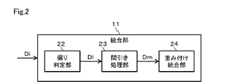
図2に示すように、統合部11は、偏り判定部22、間引き処理部23および重み付け統合部24などの機能ブロックを備える。偏り判定部22は、複数の車両から送信されたデータDiの偏りを判定する処理を実行し、その結果を表すデータDlを間引き処理部23へと出力する。偏り判定部22は、画像センサ3の車両への搭載位置、画像センサ3の仰角、俯角などに影響を及ぼす車両への搭載姿勢および画像センサ3の解像度、画角などの仕様のうち少なくとも1つに基づいたデータDiの偏りを判定することができる。また、偏り判定部22は、車両の走行速度に基づいたデータDiの偏りを判定することができる。さらに、偏り判定部22は、車両の周辺環境に基づいたデータDiの偏りを判定することができる。
As shown in FIG. 2, the
間引き処理部23は、データDlに基づいて、複数のデータDiのうち不要なデータを間引く間引き処理を実行し、その結果を表すデータDmを重み付け統合部24へと出力する。重み付け統合部24は、データDmに基づいて複数のデータDiのうち不要なデータを除くデータを重ね合わせて統合する統合処理を実行する。この場合、重み付け統合部24は、エゴモーション算出部14による自車挙動の推定精度、つまりデータDbに対応する画像を用いるとともにSFMの手法を利用して自車挙動を推定する際における推定精度に基づいてデータDiの重み付けを行うことができる。
The thinning
具体的には、統合部11は、上記した推定精度が相対的に高いと判断されるデータDiの優先度を、上記した推定精度が相対的に低いと判断されるデータDiの優先度に比べて高くするようにデータDiの重み付けを行うことができる。統合部11は、このような重み付けを行った結果、より優先度の高いデータDiを優先的に用いて地図の生成を行うことができる。
Specifically, the
次に、統合部11により実行される各処理の具体的な適用例について説明する。なお、以下では、統合部11が備える各機能ブロックのそれぞれにより実行される処理について、統合部11が実行するものとして説明する。
Next, a specific application example of each process executed by the
[1]第1適用例
第1適用例は、画像センサ3の搭載位置、姿勢、仕様などに関連する内容である。画像センサ3の搭載位置、姿勢、仕様などについては、ある状況下では地図の生成精度を向上する観点から有利になると考えられるものの、別の状況下では不利になると考えられるものがある。
[1] First Application Example The first application example is related to the mounting position, orientation, specifications, and the like of the image sensor 3 . The mounting position, orientation, specifications, etc. of the image sensor 3 are considered to be advantageous from the viewpoint of improving map generation accuracy under certain circumstances, but are considered disadvantageous under other circumstances.
例えば、画像センサ3の搭載位置が高い位置である場合、高速道路上に設けられる看板などの比較的高い位置に存在する物標までの距離が近くなりその視認性が良くなるが、逆に、路面標示など比較的低い位置に存在する物標までの距離が遠くなりその視認性が悪くなる。画像センサ3の搭載位置が比較的低い位置である場合、比較的低い位置に存在する物標までの距離が近くなりその視認性が良くなるが、逆に、比較的高い位置に存在する物標までの距離が遠くなりその視認性が悪くなる。 For example, when the mounting position of the image sensor 3 is a high position, the distance to a target existing at a relatively high position such as a signboard on an expressway is shortened and the visibility is improved. The distance to a target existing at a relatively low position such as a road marking becomes long, and its visibility deteriorates. When the mounting position of the image sensor 3 is relatively low, the distance to a target existing at a relatively low position is shortened and the visibility is improved. The distance to the target increases and its visibility deteriorates.
このようなことから、データDiが画像センサ3の搭載位置が高いデータに偏ると比較的低い位置に存在する物標に関する情報の精度が低くなるし、データDiが画像センサ3の搭載位置が低いデータに偏ると比較的高い位置に存在する物標に関する情報の精度が低くなる。そこで、統合部11は、画像センサ3の搭載位置、具体的には搭載の高さが様々なデータDiを万遍なく統合できるように、間引き処理、統合処理などを行う。このようにすれば、上記した各情報に関する精度が低くなることが抑制される。
For this reason, if the data Di is biased toward data where the mounting position of the image sensor 3 is high, the accuracy of the information on the target existing at a relatively low position will be low, If the data is biased, the accuracy of the information on the target existing at a relatively high position will be low. Therefore, the
統合部11は、特定の物標に関する情報の精度を向上させるために、次のような処理を行うこともできる。すなわち、統合部11は、比較的高い位置に存在する物標に関する情報の精度を向上させるために、画像センサ3の搭載位置の高さが比較的高いデータDiの優先度を高くするように重み付けを行うことができる。また、統合部11は、比較的低い位置に存在する物標に関する情報の精度を向上させるために、画像センサ3の搭載位置の高さが比較的低いデータDiの優先度を高くするように重み付けを行うことができる。
The
また、画像センサ3の搭載位置の高さと同じ高さの物標はフロー量が出にくい。そこで、統合部11は、画像センサ3の搭載位置の高さとのずれが大きい物標が含まれるデータDiの優先度を高くするように重み付けを行うことができる。このようにすれば、特定の物標に関する情報の精度を向上することができる。
Also, a target having the same height as the mounting position of the image sensor 3 is difficult to produce a flow amount. Therefore, the
画像センサ3の画角が比較的広い場合、車両から比較的近い位置の対象物の情報を取得するうえでは有利になるが、逆に、車両から比較的遠い位置の対象物の情報を取得するうえでは不利になる。画像センサ3の画角が比較的狭い場合、車両から比較的遠い位置の対象物の情報を取得するうえでは有利になるが、逆に、車両から比較的近い位置の対象物の情報を取得するうえでは不利になる。 When the angle of view of the image sensor 3 is relatively wide, it is advantageous in acquiring information on objects relatively close to the vehicle, but on the contrary, it acquires information on objects relatively far from the vehicle. It will be disadvantageous. When the angle of view of the image sensor 3 is relatively narrow, it is advantageous in acquiring information on objects relatively far from the vehicle, but on the contrary, it acquires information on objects relatively close to the vehicle. It will be disadvantageous.
このようなことから、データDiが画像センサ3の画角が広いデータに偏ると車両から比較的遠い位置に存在する物標に関する情報の精度が低くなるし、データDiが画像センサ3の画角が狭いデータに偏ると車両から比較的近い位置に存在する物標に関する情報の精度が低くなる。そこで、統合部11は、画像センサ3の画角が様々なデータDiを万遍なく統合できるように、間引き処理、統合処理などを行う。このようにすれば、上記した各情報に関する精度が低くなることが抑制される。
For this reason, if the data Di is biased toward data with a wide angle of view of the image sensor 3, the accuracy of information on targets existing at positions relatively far from the vehicle will be low, and the data Di will be If the data is biased toward narrow data, the accuracy of information on targets existing relatively close to the vehicle will be low. Therefore, the
統合部11は、特定の物標に関する情報の精度を向上させるために、次のような処理を行うこともできる。すなわち、統合部11は、車両から比較的近い位置に存在する物標に関する情報の精度を向上させるために、画像センサ3の画角が比較的広いデータDiの優先度を高くするように重み付けを行うことができる。また、統合部11は、車両から比較的遠い位置に存在する物標に関する情報の精度を向上させるために、画像センサ3の画角が比較的狭いデータDiの優先度を高くするように重み付けを行うことができる。
The
画像センサ3の解像度については、基本的には高いほど、地図の生成精度を向上する観点から有利になると考えられる。そこで、統合部11は、画像センサ3の解像度が比較的高いデータDiの優先度を高くするように重み付けを行うことができる。ただし、車両から比較的近い位置に存在する物標に関する情報の精度を向上させる場合または車両から比較的遠い位置に存在する物標に関する情報の精度を向上させる場合には、単に解像度が高いデータDiの優先度を高くするだけではなく、画角についても考慮したうえで、優先度を付与する必要がある。
Regarding the resolution of the image sensor 3, it is basically considered that the higher the resolution, the more advantageous from the viewpoint of improving the map generation accuracy. Therefore, the
画像センサ3が物標を正面に捉えるように撮像した画像データを含むデータDiの場合、物標の横方向への移動が少なくなるため、SFMでの距離推定の精度が低くなるおそれがある。そこで、統合部11は、隣接車線から同じ物標を撮像した画像データを含むデータDiの優先度を高くするように重み付けを行うことができる。このようにすれば、統合部11は、各物標を斜めから捉えるように撮像した画像データを含むデータDiを優先的に用いて地図の生成を行うことができるため、その精度が向上する。
In the case of the data Di including image data captured by the image sensor 3 so as to capture the target in front, the target moves less in the lateral direction, so there is a risk that the accuracy of distance estimation in SFM will be low. Therefore, the
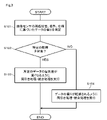
このような第1適用例において統合部11が実行する処理の流れをまとめると、図3に示すようなものとなる。図3に示すように、ステップS101では、画像センサ3の搭載位置、搭載姿勢および仕様のうち少なくとも1つに基づいたデータDiの偏りが判定される。ステップS101の実行後はステップS102に進み、特定の物標を対象としているのか否か、具体的には特定の物標に関する情報の精度を向上させる必要があるか否かが判断される。ここで、特定の物標に関する情報の精度を向上させる必要がある場合、ステップS102で「YES」となり、ステップS103に進む。
The flow of processing executed by the
ステップS103では、特定の物標に関する情報の精度を向上させるための所定のデータの優先度が高くなるように間引き処理および統合処理が行われる。一方、特定の物標に関する情報の精度を向上させる必要がない場合、ステップS102で「NO」となり、ステップS104に進む。ステップS104では、ステップS101で判定されたデータの偏りが軽減されるように間引き処理および統合処理が行われる。ステップS103またはS104の実行後、本処理が終了となる。 In step S103, thinning processing and integration processing are performed so that the priority of predetermined data for improving the accuracy of information regarding a specific target is increased. On the other hand, if it is not necessary to improve the accuracy of the information regarding the specific target, the result is "NO" in step S102, and the process proceeds to step S104. In step S104, thinning processing and integration processing are performed so as to reduce the data imbalance determined in step S101. After execution of step S103 or S104, the process ends.
[2]第2適用例
第2適用例は、車両の走行速度に関連する内容である。車両の走行速度は、速ければ早いほど、ベースラインが長くなることからSFMの精度が高くなると考えられる。しかし、車両の走行速度が速過ぎる場合には、判定に利用可能なフレーム数が少なくなることからSFMの精度が低下する可能性もある。そこで、統合部11は、車両の走行速度が様々なデータDiを万遍なく統合できるように、間引き処理、統合処理などを行う。このようにすれば、SFMの精度の低下が抑制される。
[2] Second Application Example The second application example is related to the running speed of the vehicle. It is considered that the higher the running speed of the vehicle is, the longer the baseline is, and hence the higher the accuracy of the SFM. However, if the vehicle travels too fast, the number of frames that can be used for determination is reduced, which may reduce the accuracy of the SFM. Therefore, the
ただし、このように車両の走行速度が様々なデータDiを万遍なく統合できるようにした場合、車両の周辺に位置する特定の物標についての判定回数が十分ではない可能性があり、その物標に関するSFMの精度が所定の判定精度未満になるおそれがある。なお、判定精度の値は、地図システム1の仕様に応じて適宜設定すればよい。統合部11は、車両の走行速度に応じて特定の物標に関する精度が判定精度を満たさないと判断すると、次のようにデータDiの重み付けを行うことができる。すなわち、統合部11は、車両の走行速度が比較的遅いデータDiの優先度を車両の走行速度が比較的速いデータDiの優先度に比べて高くするようにデータDiの重み付けを行うことができる。このようにすれば、特定の物標について、判定回数を増やすことができ、その結果、SFMの精度を向上させることができる。
However, in the case where data Di of various vehicle running speeds can be uniformly integrated in this way, there is a possibility that the number of determinations for a specific target located around the vehicle may not be sufficient. There is a risk that the accuracy of the SFM with respect to the target will be less than the predetermined decision accuracy. Note that the value of the determination accuracy may be appropriately set according to the specifications of the map system 1 . When the
例えば、高速道路などにおいて、同じ形状の防音壁が連続して設けられたような区間を車両が走行している場合、車両の走行速度と防音壁により形成される模様の繰り返し間隔とによっては、SFM認識部18による特徴点の対応付けの誤り、つまり誤マッチングが生じ、SFMの精度が低下するおそれがある。上記防音壁のような物標に関する精度を向上させるため、統合部11は、車両の走行速度が様々なデータDiを統合し、外れ値が大きいものについて優先度を低くしたり、除外したりすることができる。
For example, when a vehicle is traveling in a section of an expressway where soundproof walls of the same shape are continuously provided, depending on the running speed of the vehicle and the pattern repetition interval formed by the soundproof walls, There is a possibility that the
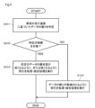
このような第2適用例において統合部11が実行する処理の流れをまとめると、図4に示すようなものとなる。図4に示すように、ステップS201では、車両の走行速度に基づいたデータDiの偏りが判定される。ステップS201の実行後はステップS202に進み、特定の物標を対象としているのか否か、具体的には特定の物標に関する情報の精度を向上させる必要があるか否かが判断される。ここで、特定の物標に関する情報の精度を向上させる必要がある場合、ステップS202で「YES」となり、ステップS203に進む。
The flow of processing executed by the
ステップS203では、特定の物標に関する情報の精度を向上させるための所定のデータの優先度が高くなるように、または低くなるように、間引き処理および統合処理が行われる。一方、特定の物標に関する情報の精度を向上させる必要がない場合、ステップS202で「NO」となり、ステップS204に進む。ステップS204では、ステップS201で判定されたデータの偏りが軽減されるように間引き処理および統合処理が行われる。ステップS203またはS204の実行後、本処理が終了となる。 In step S203, thinning processing and integration processing are performed so that the priority of predetermined data for improving the accuracy of information regarding a specific target is increased or decreased. On the other hand, if it is not necessary to improve the accuracy of the information regarding the specific target, the result is "NO" in step S202, and the process proceeds to step S204. In step S204, thinning processing and integration processing are performed so as to reduce the data imbalance determined in step S201. After execution of step S203 or S204, this process ends.
[3]第3適用例
第3適用例は、車両の周辺の明るさなどの環境に関連する内容である。車両の周辺の明るさが明るい場合、SFMの精度に影響を及ぼすノイズが少なくなることから、地図の生成精度を向上する観点から有利になると考えられる。しかし、車両の周辺の明るさが明るい場合、一部の電光表示などが白飛びして見えなくなったり、電光標識においてフリッカーが生じたりすることが考えられ、その結果、それら物標に関する精度が低下する可能性がある。
[3] Third Application Example The third application example is related to the environment such as the brightness around the vehicle. When the surroundings of the vehicle are bright, the amount of noise that affects the accuracy of the SFM is reduced, which is considered to be advantageous from the viewpoint of improving the accuracy of map generation. However, if the surroundings of the vehicle are bright, some electric displays may become overexposed and may not be visible, and electric signs may flicker. there's a possibility that.
そこで、統合部11は、車両の周辺の明るさが様々な画像データを含むデータDiを万遍なく統合できるように、言い換えると、車両の周辺の明るさが明るい時間帯である昼間に撮像された画像データを含むデータDiと車両の周辺の明るさが暗い時間帯である夜間に撮像された画像データを含むデータDiとを万遍なく統合できるように、間引き処理、統合処理などを行う。このようにすれば、SFMの精度の低下が抑制される。
Therefore, the
統合部11は、特定の物標に関する情報の精度を向上させるために、次のような処理を行うこともできる。すなわち、統合部11は、上記した一部の電光表示、電光標識など以外の物標に関する情報の精度を向上させるために、車両の周辺の明るさが明るい時間帯、例えば昼間に撮像された画像データを含むデータDiの優先度を高くするように重み付けを行うことができる。また、統合部11は、上記した一部の電光表示、電光標識などの物標に関する情報の精度を向上させるために、車両の周辺の明るさが暗い時間帯、例えば夜間に撮像された画像データを含むデータDiの優先度を高くするように重み付けを行うことができる。
The
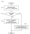
このような第3適用例において統合部11が実行する処理の流れをまとめると、図5に示すようなものとなる。図5に示すように、ステップS301では、車両の周辺の明るさに基づいたデータDiの偏りが判定される。ステップS301の実行後はステップS302に進み、特定の物標を対象としているのか否か、具体的には特定の物標に関する情報の精度を向上させる必要があるか否かが判断される。ここで、特定の物標に関する情報の精度を向上させる必要がある場合、ステップS302で「YES」となり、ステップS303に進む。
The flow of processing executed by the
ステップS303では、特定の物標に関する情報の精度を向上させるための所定のデータの優先度が高くなるように間引き処理および統合処理が行われる。一方、特定の物標に関する情報の精度を向上させる必要がない場合、ステップS302で「NO」となり、ステップS304に進む。ステップS304では、ステップS301で判定されたデータの偏りが軽減されるように間引き処理および統合処理が行われる。ステップS303またはS304の実行後、本処理が終了となる。 In step S303, thinning processing and integration processing are performed so that the priority of predetermined data for improving the accuracy of information on a specific target is increased. On the other hand, if there is no need to improve the accuracy of the information regarding the specific target, the result is "NO" in step S302, and the process proceeds to step S304. In step S304, thinning processing and integration processing are performed so as to reduce the data imbalance determined in step S301. After execution of step S303 or S304, this process ends.
[4]第4適用例
第4適用例は、車両の状態に関連する内容である。車両のイグニッションスイッチがオンされた直後には、SF補正部13によるスケールファクタの補正に関する精度が低下し、その結果、SFMの精度が低下するおそれがある。そこで、統合部11は、車両のイグニッションスイッチがオンされた時点からの経過時間が比較的短いデータDiの優先度を低くするように重み付けを行う。このようにすれば、SFMの精度の低下が抑制される。
[4] Fourth Application Example A fourth application example relates to the state of the vehicle. Immediately after the ignition switch of the vehicle is turned on, the accuracy of the scale factor correction by the
[5]第5適用例
第5適用例は、撮像の時間帯に関連する内容である。道路には、時間帯に応じて道路区分が変わるものがあり、そのような道路に関する特定の情報は、特定の時間でしか精度良く取得できない可能性がある。そこで、統合部11は、画像データの撮像の時間帯が様々なデータDiを万遍なく統合できるように、間引き処理、統合処理などを行う。このようにすれば、時間帯に応じて道路区分が変わるような道路に関する情報を精度良く取得することができる。
[5] Fifth Application Example The fifth application example is related to the imaging time period. Some roads have different road classifications depending on the time of day, and there is a possibility that specific information about such roads can be obtained with high accuracy only at specific times. Therefore, the
以上説明したように、本実施形態の地図システム1は、車両に搭載され車両の周辺の画像を撮像する画像センサ3を備えた車両用装置9と、車両用装置9から送信される画像センサ3により撮像された画像に対応するデータを用いて地図を生成するサーバ2と、を備えたシステムである。サーバ2の制御装置10は、複数の車両用装置9から送信されるデータの偏りに基づいてデータに重み付けを行い、その重み付けに基づいて複数のデータの少なくとも一部を統合して地図を生成する統合部11を備える。
As described above, the map system 1 of the present embodiment includes the vehicle device 9 equipped with the image sensor 3 mounted on the vehicle and capturing an image of the surroundings of the vehicle, and the image sensor 3 transmitted from the vehicle device 9. and a
上記構成によれば、複数の車両用装置9からサーバ2に送信されるデータ、つまりプローブデータに偏りがある場合でも、その偏りに基づいてデータに重み付けが行われ、その重み付けを考慮して地図が生成される。このような構成によれば、従来に比べ、車両用装置9からサーバ2に送信されるデータの数が少なくとも、サーバ2は、より精度の高い地図を生成することができる。したがって、本実施形態によれば、サーバ2での地図の生成精度を高めることができるという優れた効果が得られる。
According to the above configuration, even if there is a bias in the data transmitted from the plurality of vehicle devices 9 to the
本実施形態の処理の具体的な適用例である第1適用例、第2適用例、第3適用例および第4適用例によれば、統合部11は、SFMの手法を利用した自車挙動の推定精度が相対的に高いと判断されるデータDiの優先度を、上記した推定精度が相対的に低いと判断されるデータDiの優先度に比べて高くするようにデータDiの重み付けを行うことができる。統合部11は、このような重み付けを行った結果、より優先度の高いデータDiを優先的に用いて地図の生成を行うことができる。サーバ2での統合地図の精度を向上するための1つの指標として、上記したSFMの精度を向上することが挙げられる。したがって、上記したような具体的な処理によれば、サーバ2での地図の生成精度を一層高めることができる。
According to the first application example, the second application example, the third application example, and the fourth application example, which are specific application examples of the processing of the present embodiment, the
(第2実施形態)
以下、第2実施形態について図6~図9を参照して説明する。
図6に示すように、本実施形態の地図システム31は、第1実施形態の地図システム1に対し、車両用装置9に代えて車両用装置32を備えている点などが異なる。車両用装置32の制御装置33は、車両用装置9の制御装置8に対し、道路勾配推定部34および視認性推定部35という2つの機能ブロックが追加されている点、地図生成部16に代えて地図生成部36が設けられている点などが異なっている。
(Second embodiment)
The second embodiment will be described below with reference to FIGS. 6 to 9. FIG.
As shown in FIG. 6, the
道路勾配推定部34は、画像センサ3により撮像された画像を表すデータDbに基づいて所定の機械学習を行い、それにより画像センサ3により撮像された画像上における道路の勾配を推定する。道路勾配推定部34は、推定した道路勾配を表すデータDnを地図生成部36へと出力する。視認性推定部35は、画像センサ3により撮像された画像を表すデータDbに基づいて所定の機械学習を行い、それにより画像センサ3における視認性を推定する。視認性推定部35は、推定した視認性を表すデータDoを地図生成部36へと出力する。
The
地図生成部36は、地図情報生成部37および信頼度付与部38を備えている。地図生成部36には、エゴモーション算出部14からデータDeに加えデータDdも与えられている。地図情報生成部37は、第1実施形態の地図生成部16と同様に地図情報を生成する。信頼度付与部38は、画像センサ3により撮像された画像に対応するデータの信頼度に関する情報である信頼度情報をデータDiに付与する。信頼度付与部38は、各機能ブロックから入力される信頼度基データに基づいて画像に対応するデータの信頼度を評価し、その評価結果に基づいて信頼度情報を生成する。
The
信頼度情報は、サーバ2の統合部11において利用される情報となる。すなわち、統合部11は、前述したように、複数の車両用装置から送信される画像に対応するデータの偏りに基づいてデータDiに重み付けを行い、その重み付けに基づいて複数のデータDiの少なくとも一部を統合して地図を生成する。この場合、統合部11は、データDiに付与された信頼度情報も考慮してデータDiを統合して地図を生成するようになっている。例えば、統合部11は、比較的高い信頼度を表す信頼度情報が付与されたデータDiを優先的に用いて統合することができる。なお、ここで言う「画像に対応するデータ」は、画像センサ3による画像の撮像状況に関するデータ、つまり単なるランドマークや車線情報ではなく、画像センサ3の搭載位置、画角、解像度、車両速度、車両環境や信頼度といったデータである。
The reliability information is information used in the
エゴモーション算出部14から入力されるデータDdを情報源とする信頼度基データとしては、SFM低精度フラグが挙げられる。SFM低精度フラグは、エゴモーションの推定精度が低下している可能性がある場合にオンされるものである。ランドマーク検出部15から入力されるデータDhを情報源とする信頼度基データとしては、設置位置、サイズ、種別、色、SFM位置推定成功回数、連続外挿回数、SFM位置推定成功時の位置、SFMの点数、SFM点群のばらつき度合い、SFM点群の属性などが挙げられる。
The SFM low-accuracy flag is an example of the reliability-based data whose information source is the data Dd input from the
設置位置は、自車位置から見たランドマークの設置位置である。なお、設置位置は、区画線の場合はフィッティング誤差である。設置位置に基づいた信頼度評価の具体例としては、例えば、標識であるにもかかわらず、路面上に設置位置がある場合には誤検出の可能性が高いと推定することができる、といった例が挙げられる。サイズは、ランドマークの大きさである。なお、サイズは、区画線の場合は線幅である。サイズに基づいた信頼度評価の具体例としては、例えば標識であるにもかかわらず、その四方が0.2m未満である場合、アスペクト比が異常な値である場合などには誤検出の可能性が高いと推定することができる、といった例が挙げられる。 The installation position is the installation position of the landmark viewed from the vehicle position. Note that the installation position is a fitting error in the case of the partition line. As a specific example of reliability evaluation based on the installation position, for example, even though it is a sign, if the installation position is on the road surface, it can be estimated that the possibility of false detection is high. is mentioned. The size is the size of the landmark. Note that the size is the line width in the case of the marking line. As a specific example of reliability evaluation based on size, there is a possibility of false detection if the square is less than 0.2m even though it is a sign, or if the aspect ratio is an abnormal value. can be estimated to be high.
種別に基づいた信頼度評価の具体例としては、例えば、標識の場合には何の標識であるのか、あるいは標識では無さそうかの判定、区画線の場合には線種の識別が行われるため、それら判定の結果、識別の結果によっては誤検出の可能性を疑うことができる、といった例が挙げられる。色に基づいた信頼度評価の具体例としては、例えば、区画線の場合には線色の識別が行われるため、線色が白色または黄色のいずれでもないと判定される場合には誤検出の可能性がある、といった例が挙げられる。 As a specific example of reliability evaluation based on type, for example, in the case of a sign, it is determined what kind of sign it is or whether it is not a sign, and in the case of a lane marking, the line type is identified. , the possibility of erroneous detection can be suspected depending on the results of these determinations and the results of identification. As a specific example of reliability evaluation based on color, for example, in the case of lane markings, the color of the line is identified. Here are some examples of what is possible.
SFM位置推定成功回数は、SFMの点を使った3次元位置推定に成功した回数、具体的には積算値である。SFM位置推定成功回数は多いほうがよく、その場合にはランドマークである可能性が高まる。そこで、SFM位置推定成功回数に基づいた信頼度評価の具体例としては、SFM位置推定成功回数が極端に少ない場合には画像に特徴点がない、つまりランドマークではない可能性を疑うことができる、といった例が挙げられる。 The SFM position estimation success count is the number of successful three-dimensional position estimations using SFM points, specifically, an integrated value. A larger number of successful SFM position estimations is better, and in that case the possibility of being a landmark increases. Therefore, as a specific example of reliability evaluation based on the number of successful SFM position estimations, when the number of successful SFM position estimations is extremely small, the possibility that the image has no feature points, that is, is not a landmark can be suspected. , are examples.
連続外挿回数は、SFMによる位置推定ができずエゴモーションから位置予測した回数である。連続外挿回数は少ないほうがよく、その場合にはランドマークである可能性が高まる。そこで、連続外挿回数に基づいた信頼度評価の具体例としては、連続外挿回数が極端に多い場合には画像に特徴点がない、つまりランドマークではない可能性、距離精度が低い可能性などを疑うことができる、といった例が挙げられる。 The number of times of continuous extrapolation is the number of times the position was predicted from the egomotion when the position could not be estimated by the SFM. A smaller number of consecutive extrapolations is better, which increases the likelihood of being a landmark. Therefore, as a specific example of reliability evaluation based on the number of consecutive extrapolations, if the number of consecutive extrapolations is extremely large, the image may have no feature points, that is, it may not be a landmark, and the distance accuracy may be low. For example, it is possible to suspect that
SFM位置推定成功時の位置は、SFMによる位置推定に成功したときのランドマークの設置位置である。SFM位置推定成功時の位置に基づいた信頼度評価の具体例としては、原則遠方にあるものほど距離精度が低い、といった例が挙げられる。SFMの点数に基づいた信頼度評価の具体例としては、位置推定は認識したランドマークに当たっている特徴点の平均を取るなどして行われるため、特徴点が多いほど距離精度が高い可能性が高くなる、といった例が挙げられる。 The position at the time of successful SFM position estimation is the installation position of the landmark when the position estimation by SFM is successful. As a specific example of position-based reliability evaluation when SFM position estimation is successful, there is an example in which, in principle, the farther the object, the lower the distance accuracy. As a specific example of reliability evaluation based on SFM scores, position estimation is performed by taking the average of feature points that hit recognized landmarks, so the more feature points there are, the higher the possibility of distance accuracy being. Examples include becoming.
SFM点群のばらつき度合いに基づいた信頼度評価の具体例としては、次のような例が挙げられる。すなわち、SFM点群のばらつき度合いが大きいほど、信頼度が低くなる。特に奥行方向の距離がばらつく場合、ランドマークである可能性が低くなる。なぜなら、ランドマークは、基本的にはフラットなものであるため、ランドマーク上の各特徴点についての奥行方向の距離は一定になるはずである。そのため、奥行方向の距離にばらつきがあるということは、その対象物がランドマークではない可能性が高くなる。 Specific examples of reliability evaluation based on the degree of dispersion of the SFM point cloud include the following examples. That is, the greater the degree of variation in the SFM point cloud, the lower the reliability. Especially when the distance in the depth direction varies, the possibility of being a landmark decreases. This is because landmarks are basically flat, so the distance in the depth direction for each feature point on the landmark should be constant. Therefore, if there is variation in the distance in the depth direction, there is a high possibility that the object is not a landmark.
SFM点群の属性に基づいた信頼度評価の具体例としては、次のような例が挙げられる。すなわち、SFMの点は、セグメンテーション、つまり道路標識、区画線などの属性の情報を持っているため、同じ属性を持つ特徴点の割合が多いほど精度が高いことになる。つまり、該当するランドマークのセグメンテーションを持つ特徴点の割合が高いほど距離精度が高くなる。 Specific examples of reliability evaluation based on the attributes of the SFM point cloud include the following examples. That is, since SFM points have attribute information such as segmentation, that is, road signs and lane markings, the higher the ratio of feature points having the same attribute, the higher the accuracy. That is, the higher the percentage of feature points with corresponding landmark segmentation, the higher the distance accuracy.
道路勾配推定部34から入力されるデータDnを情報源とする信頼度基データとしては、道路勾配推定状態、フィッティング誤差などが挙げられる。道路勾配推定状態は、道路勾配を推定できているかどうかを表すものである。道路勾配推定状態に基づいた信頼度評価の具体例としては、道路勾配を推定できていない場合には上り下り勾配のデータの精度が低下する、といった例が挙げられる。フィッティング誤差は、勾配推定の精度であり、具体的にはフィッティング曲線とSFMの点のずれ量の平均である。フィッティング誤差に基づいた信頼度評価の具体例としては、フィッティング誤差のばらつきが大きい場合には精度が低い、といった例が挙げられる。
The reliability base data whose information source is the data Dn input from the road
視認性推定部35から入力されるデータDoを情報源とする信頼度基データとしては、トンネルフラグ、ガラス曇りレベル、レンズ遮蔽レベル、悪天候レベル、逆光レベル、雨滴付着レベル、路面雪レベル、砂漠レベル、泥濘レベル、路面濡れレベルなどが挙げられる。トンネルフラグは、トンネルを通過中にオンされるフラグである。トンネルで同じ背景が連続する場合はSFMエゴモーション精度が低下する要因となる。そこで、トンネルフラグがオンのときには精度が低いといった信頼度評価を行うことができる。
The reliability base data whose information source is the data Do input from the
ガラス曇りレベルは、車両のフロントガラスの曇り具合を表すものであり、そのレベルに応じて信頼度評価を行うことができる。レンズ遮蔽レベルは、背景が隠されている具合を表すものであり、そのレベルに応じて信頼度評価を行うことができる。悪天候レベルは、豪雨、濃霧、豪雪、砂塵などの悪天候の具合を表すものであり、そのレベルに応じて信頼度評価を行うことができる。 The fogging level of the windshield indicates the degree of fogging of the windshield of the vehicle, and the reliability can be evaluated according to the level. The lens shielding level indicates how much the background is hidden, and reliability can be evaluated according to the level. The bad weather level represents the condition of bad weather such as heavy rain, dense fog, heavy snow, and dust, and reliability can be evaluated according to the level.
逆光レベルは、昼の場合には太陽の光に起因する逆光の具合、夜の場合にはライトなどの光に起因する逆光の具合を表すものであり、そのレベルに応じて信頼度評価を行うことができる。雨滴付着レベルは、車両のフロントガラスへの雨滴の付着具合を表すものであり、そのレベルに応じて信頼度評価を行うことができる。路面雪レベルは、路面に雪があるか否かを表すものであり、そのレベルに応じて信頼度評価を行うことができる。 The backlight level indicates the degree of backlighting caused by sunlight in the daytime, and the degree of backlighting caused by light such as lights at night, and reliability is evaluated according to the level. be able to. The raindrop adhesion level represents the degree of adhesion of raindrops to the windshield of the vehicle, and reliability can be evaluated according to the level. The road surface snow level indicates whether or not there is snow on the road surface, and reliability can be evaluated according to the level.
砂漠レベルは、路面が砂漠であるかどうかを表すものであり、そのレベルに応じて信頼度評価を行うことができる。泥濘レベルは、路面が泥濘であるかどうかを表すものであり、そのレベルに応じて信頼度評価を行うことができる。路面濡れレベルは、路面が雨などにより濡れているかどうかを表すものであり、そのレベルに応じて信頼度評価を行うことができる。これら各レベルに基づいた信頼度評価は、多段階、例えば3段階で行うことができる。 The desert level indicates whether the road surface is desert or not, and reliability evaluation can be performed according to the level. The muddy level indicates whether the road surface is muddy or not, and the reliability can be evaluated according to the level. The road surface wetness level indicates whether the road surface is wet due to rain or the like, and reliability can be evaluated according to the level. Reliability evaluation based on each of these levels can be performed in multiple stages, for example, in three stages.
GPS情報を表すデータDaを情報源とする信頼度基データとしては、GNSS方位角、GNSS速度、DOPなどが挙げられる。なお、GNSSは、Global Navigation Satellite Systemの略称であり、DOPは、Dilution Of Precisionの略称である。GNSS方位角は、GNSS測位により得られる車両の方位角、つまりヨー角を表すものである。GNSS方位角に基づいた信頼度評価の具体例としては、車両がヨーレートセンサなどから演算するヨー角との差が大きい場合にGNSS精度が低いと判断することができる、といった例が挙げられる。 GNSS azimuth, GNSS velocity, DOP, and the like are examples of reliability base data whose information source is data Da representing GPS information. GNSS is an abbreviation for Global Navigation Satellite System, and DOP is an abbreviation for Dilution Of Precision. The GNSS azimuth angle represents the azimuth angle of the vehicle obtained by GNSS positioning, that is, the yaw angle. As a specific example of the reliability evaluation based on the GNSS azimuth angle, it is possible to determine that the GNSS accuracy is low when the vehicle has a large difference from the yaw angle calculated from a yaw rate sensor or the like.
GNSS速度は、GNSS測位により得られる車両の走行速度である。GNSS速度に基づいた信頼度評価の具体例としては、車両が車輪速センサなどから演算する車速との差が大きい場合にGNSS精度が低いと判断することができる、といった例が挙げられる。DOPは、精度低下率のことであり、一般的に数値が小さいほどGNSSの測位結果の精度が高いことを示す。そこで、DOPに基づいた信頼度評価の具体例としては、その数値が小さいほど精度が高いと判断することができる、といった例が挙げられる。 The GNSS speed is the running speed of the vehicle obtained by GNSS positioning. As a specific example of the reliability evaluation based on the GNSS speed, it can be determined that the GNSS accuracy is low when the difference between the vehicle speed calculated from the wheel speed sensor and the like is large. DOP is a precision reduction rate, and generally, the smaller the value, the higher the precision of the GNSS positioning results. Therefore, as a specific example of the reliability evaluation based on the DOP, it is possible to judge that the smaller the numerical value, the higher the accuracy.
このように、信頼度付与部38は、データDiに対応する画像を用いるとともにSFMの手法を利用して車両の挙動である自車挙動を推定する際における推定精度に基づいて信頼度を評価し、その評価結果に基づいて信頼度情報を生成する。また、信頼度付与部38は、道路勾配の推定精度に基づいて信頼度を評価し、その評価結果に基づいて信頼度情報を生成する。また、信頼度付与部38は、画像センサ3における視認性の推定精度に基づいて信頼度を評価し、その評価結果に基づいて信頼度情報を生成する。また、信頼度付与部38は、データDiに対応する画像に基づいて検出される画像上におけるランドマークに関する情報に基づいて信頼度を評価し、その評価結果に基づいて信頼度情報を生成する。
In this way, the
続いて、信頼度付与部38による信頼度情報の生成に関する具体的な手法について説明する。
[1]第1手法
第1手法では、信頼度付与部38は、信頼度基データに基づいて「基礎点」および「係数」を決定し、基礎点に係数を乗じることで信頼度を求める。例えば、信頼度は、「1」~「100」の数値で示される100段階とし、数値が小さいほど信頼度が低いものとすることができる。なお、この場合、基礎点についても、信頼度と同様、「1」~「100」の数値で示される100段階とされる。
Next, a specific method for generating reliability information by the
[1] First Method In the first method, the
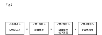
具体的には、信頼度付与部38は、信頼度基データに基づいて少なくとも1つの基礎点を算出する。例えば、標識の場合、サイズが規定値内であり、且つ、制限速度標識であるなどの標識の種別が特定できているときには、基礎点を100とする。そして、信頼度付与部38は、信頼度基データに基づいて少なくとも1つの係数を算出する。なお、係数は、1.0以下の値とされる。例えば、連続外挿回数が多いほど係数を低めに設定したり、位置推定時の位置が自車位置から一定値以上遠いほど係数を低めに設定したりすることが考えられる。
Specifically, the
第1手法による信頼度情報生成の具体的な事例としては、例えば図7に示すようなものを挙げることができる。なお、図7などでは、ランドマークのことをLMKと省略している。この場合、基礎点は、ランドマークらしさを表す内容となっている。また、この場合、係数は、第1係数、第2係数および第3係数の3つが設定されている。第1係数は、距離精度に関する内容となっている。第2係数は、認識精度低下要因、つまり視認性低下要因に関する内容となっている。第3係数は、その他精度に関する内容となっている。なお、その他精度としては、道路勾配の推定精度、SFMの精度、GNSSの精度などが挙げられる。図7に示す第1手法による具体的な事例では、基礎点に対し、第1係数、第2係数および第3係数が乗算されることにより、信頼度が算出される。 A specific example of reliability information generation by the first method is shown in FIG. 7, for example. Note that landmarks are abbreviated as LMK in FIG. 7 and the like. In this case, the basic points have contents that represent the likeness of the landmark. Also, in this case, three coefficients, ie, a first coefficient, a second coefficient, and a third coefficient are set. The first coefficient has content related to distance accuracy. The second coefficient is a content related to a recognition accuracy reduction factor, that is, a visibility reduction factor. The third coefficient has contents related to other accuracy. In addition, as other accuracies, estimation accuracy of road slope, accuracy of SFM, accuracy of GNSS, and the like can be mentioned. In a specific example of the first method shown in FIG. 7, the reliability is calculated by multiplying the base point by the first, second and third coefficients.
[2]第2手法
第2手法では、信頼度付与部38は、信頼度基データから2つ以上の基礎点を算出し、それら2つ以上の基礎点を加算することで信頼度を求める。この場合、全ての基礎点の合計が「100」となるように、各基礎点は、それぞれが均等となるように、または、それぞれに重み付けが行われるように、振り分ければよい。
[2] Second Method In the second method, the
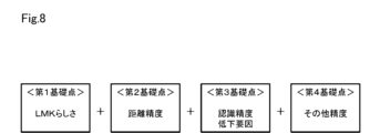
第2手法による信頼度情報生成の具体的な事例としては、例えば図8に示すようなものを挙げることができる。この場合、基礎点は、第1基礎点、第2基礎点、第3基礎点および第4基礎点の4つが設定されている。第1基礎点は、ランドマークらしさを表す内容となっている。第2基礎点は、距離精度に関する内容となっている。第3基礎点は、認識精度低下要因に関する内容となっている。第4基礎点は、その他精度に関する内容となっている。 A specific example of reliability information generation by the second method is shown in FIG. 8, for example. In this case, four base points are set: a first base point, a second base point, a third base point, and a fourth base point. The first base point has a content that expresses the likeness of a landmark. The second basic point has contents related to distance accuracy. The third basic point is the content related to recognition accuracy degradation factors. The fourth basic point has other contents related to accuracy.
この場合、各基礎点は、それぞれに重み付けが行われるように振り分けが行われている。具体的には、第1基礎点は「1」~「60」の数値で示される60段階とされ、第2基礎点は「1」~「20」の数値で示される20段階とされ、第3基礎点および第4基礎点は「1」~「10」の数値で示される10段階とされている。図8に示す第2手法による具体的な事例では、第1基礎点、第2基礎点、第3基礎点および第4基礎点が加算されることにより、信頼度が算出される。 In this case, each base point is distributed so as to be individually weighted. Specifically, the first base point is set to 60 levels indicated by numerical values from "1" to "60", the second base point is set to 20 levels indicated by numerical values from "1" to "20", The 3rd base point and the 4th base point are set to 10 levels indicated by numerical values from "1" to "10". In a specific example of the second method shown in FIG. 8, the reliability is calculated by adding the first, second, third, and fourth basic points.
[3]第3手法
第3手法では、信頼度付与部38は、信頼度基データから2つ以上の基礎点を算出し、それら2つ以上の基礎点をそれぞれ評価することで信頼度を求める。この場合、各基礎点は、いずれも「1」~「100」の数値で示される100段階とされる。第3手法による信頼度情報生成の具体的な事例としては、例えば図9に示すようなものを挙げることができる。この場合、基礎点は、第2手法と同様、第1基礎点、第2基礎点、第3基礎点および第4基礎点の4つが設定されている。図9に示す第3手法による具体的な事例では、第1基礎点、第2基礎点、第3基礎点および第4基礎点のそれぞれが個別に評価されることにより、信頼度が算出される。
[3] Third method In the third method, the
以上説明した本実施形態によれば、車両用装置32において、地図生成部36は、第1実施形態の地図生成部16と同様に地図情報を生成する地図情報生成部37と、画像センサ3により撮像された画像に対応するデータの信頼度に関する情報である信頼度情報をサーバ2にアップロードするプローブデータであるデータDiに付与する信頼度付与部38と、を備えている。そして、本実施形態では、サーバ2において、統合部11は、データDiに付与された信頼度情報も考慮してデータDiを統合して地図を生成する。このようにすれば、サーバ2での地図の生成精度を一層高めることができるという優れた効果が得られる。
According to the present embodiment described above, in the
(その他の実施形態)
なお、本発明は上記し且つ図面に記載した各実施形態に限定されるものではなく、その要旨を逸脱しない範囲で任意に変形、組み合わせ、あるいは拡張することができる。
上記各実施形態で示した数値などは例示であり、それに限定されるものではない。
(Other embodiments)
The present invention is not limited to the embodiments described above and illustrated in the drawings, and can be arbitrarily modified, combined, or expanded without departing from the scope of the invention.
The numerical values and the like shown in each of the above embodiments are examples, and are not limited to them.
地図システム1、31において、それぞれの機能ブロックは分散されていてもよい。例えば、サーバ2側の制御装置10が備える各機能ブロックの一部が、車両側、つまり車両用装置9、32側の制御装置8、33に設けられ、各制御装置が通信を介して各種データの送受信を行うことにより、上記各実施形態で説明した各処理を実行する構成としてもよい。このような構成の具体例として、次のような構成を挙げることができる。
In the
すなわち、サーバ2は、統合地図を表すデータDjとともに、例えば夜間に撮像された画像データを含むデータが少ない、画像センサ3の搭載位置が低い位置のデータが少ないなど、不足しているプローブデータの属性を付与する。車両用装置9、32は、自車両が上記属性に合致するか否かを判断し、合致すると判断した場合にだけデータDiをアップロードする。このようにすれば、通信量を抑制しつつ、サーバ2が必要とするプローブデータだけを効率よく収集することができる。
That is, together with the data Dj representing the integrated map, the
また、第2実施形態について、車両用装置32の制御装置33に設けられる信頼度付与部38は、サーバ2の制御装置10に設けることができる。この場合、車両用装置32は、サーバ2に対し、信頼度基データを送信するような構成とすればよい。そして、この場合、サーバ2に設けられた信頼度付与部38は、車両用装置32から送信される信頼度基データに基づいて信頼度情報を生成し、その信頼度情報を車両用装置32からアップロードされるデータDiに付与することになる。
Further, in the second embodiment, the
第2実施形態の車両用装置32では、原則、画像センサ3により撮像された画像に対応するデータについては、過去の情報は残さないようになっている。そして、車両用装置32では、所定のランドマークについては、そのランドマークが画像センサ3による撮像画像から見切れる直前のデータをサーバ2にアップロードするようになっている。そのため、サーバ2にデータDiをアップロードする時点では、その時点のフレームにおける信頼度基データによる評価しかできないことになり、信頼度の評価の精度が低くなるおそれがある。
In principle, the
例えば、あるフレームでは道路標識であると認識されたが、別のフレームでは電灯であると認識されるなど、ランドマークの属性に関する情報は毎フレーム異なる可能性がある。そこで、車両用装置32では、各信頼度基データを時系列で記憶させておき、それらのうち頻度が多いのを採用して係数化したり、ばらつき度合いを係数化したりする、とよい。このようにすれば、信頼度の評価の精度を良好に維持すること、ひいてはサーバ2での地図の生成精度を良好に維持することができる。
For example, information about landmark attributes may differ from frame to frame, such as being recognized as a road sign in one frame, but being recognized as an electric light in another frame. Therefore, in the
第2実施形態の車両用装置32では、信頼度情報に基づいてデータDiを選別してアップロードすることになるが、信頼度情報が表すデータの信頼度が必ずしも正確であるとは言い切れない。そのため、車両用装置32では、極力データDiを排除することなく、出来る限り多くのデータDiをアップロードする、といった対応を行うことが望ましい。そして、この場合、サーバ2の統合部11は、本当に必要であると考えられるデータDiを取捨選択して統合を行うようにすればよい。
In the
本開示は、実施例に準拠して記述されたが、本開示は当該実施例や構造に限定されるものではないと理解される。本開示は、様々な変形例や均等範囲内の変形をも包含する。加えて、様々な組み合わせや形態、さらには、それらに一要素のみ、それ以上、あるいはそれ以下、を含む他の組み合わせや形態をも、本開示の範疇や思想範囲に入るものである。 Although the present disclosure has been described with reference to examples, it is understood that the present disclosure is not limited to such examples or structures. The present disclosure also includes various modifications and modifications within the equivalent range. In addition, various combinations and configurations, as well as other combinations and configurations, including single elements, more, or less, are within the scope and spirit of this disclosure.
本開示に記載の制御部及びその手法は、コンピュータプログラムにより具体化された一つ乃至は複数の機能を実行するようにプログラムされたプロセッサ及びメモリを構成することによって提供された専用コンピュータにより、実現されてもよい。あるいは、本開示に記載の制御部及びその手法は、一つ以上の専用ハードウェア論理回路によってプロセッサを構成することによって提供された専用コンピュータにより、実現されてもよい。もしくは、本開示に記載の制御部及びその手法は、一つ乃至は複数の機能を実行するようにプログラムされたプロセッサ及びメモリと一つ以上のハードウェア論理回路によって構成されたプロセッサとの組み合わせにより構成された一つ以上の専用コンピュータにより、実現されてもよい。また、コンピュータプログラムは、コンピュータにより実行されるインストラクションとして、コンピュータ読み取り可能な非遷移有形記録媒体に記憶されていてもよい。 The controller and techniques described in this disclosure may be implemented by a dedicated computer provided by configuring a processor and memory programmed to perform one or more functions embodied by the computer program. may be Alternatively, the controls and techniques described in this disclosure may be implemented by a dedicated computer provided by configuring the processor with one or more dedicated hardware logic circuits. Alternatively, the control units and techniques described in this disclosure can be implemented by a combination of a processor and memory programmed to perform one or more functions and a processor configured by one or more hardware logic circuits. It may also be implemented by one or more dedicated computers configured. The computer program may also be stored as computer-executable instructions on a computer-readable non-transitional tangible recording medium.
1、31…地図システム、2…サーバ、3…画像センサ、9、32…車両用装置、11…統合部、38…信頼度付与部。 1, 31... map system, 2... server, 3... image sensor, 9, 32... vehicle device, 11... integrating section, 38... reliability giving section.
Claims (13)
複数の前記車両用装置から送信される前記データの偏りに基づいて前記データに重み付けを行い、その重み付けに基づいて複数の前記データの少なくとも一部を統合して前記地図を生成する統合部(11)を備え、
前記統合部は、前記データに対応する画像を用いるとともにStructure From Motionの手法を利用して前記車両の挙動である自車挙動を推定する際における推定精度が相対的に高いと判断される前記データの優先度を前記推定精度が相対的に低いと判断される前記データの優先度に比べて高くするように前記データの重み付けを行う地図システム。 A vehicle device (9, 32) equipped with an imaging device (3) mounted on a vehicle and configured to capture an image of the surroundings of the vehicle; A map system (1, 31) comprising a server (2) that generates a map using data corresponding to feature points in the
an integration unit (11) for weighting the data based on the bias of the data transmitted from the plurality of vehicle devices, and integrating at least a part of the plurality of data based on the weighting to generate the map; ) ,
The integration unit uses the image corresponding to the data and uses the Structure From Motion technique to estimate the behavior of the own vehicle, which is the behavior of the vehicle. A map system that weights the data so that the priority of the data is higher than the priority of the data determined to have relatively low estimation accuracy .
複数の前記車両用装置から送信される前記データの偏りに基づいて前記データに重み付けを行い、その重み付けに基づいて複数の前記データの少なくとも一部を統合して前記地図を生成する統合手順を、
実行させ、
前記統合手順では、前記データに対応する画像を用いるとともにStructure From Motionの手法を利用して前記車両の挙動である自車挙動を推定する際における推定精度が相対的に高いと判断される前記データの優先度を前記推定精度が相対的に低いと判断される前記データの優先度に比べて高くするように前記データの重み付けを行う地図生成プログラム。 A vehicle device (9, 32) equipped with an imaging device (3) mounted on a vehicle and configured to capture an image of the surroundings of the vehicle; a server (2) that generates a map using data corresponding to feature points in both , or only said server,
weighting the data based on the bias of the data transmitted from the plurality of vehicle devices, and integrating at least a portion of the plurality of data based on the weighting to generate the map;
let it run ,
In the integration procedure, the data that is determined to have relatively high estimation accuracy when estimating the own vehicle behavior, which is the behavior of the vehicle, by using the image corresponding to the data and using the Structure From Motion method. A map generation program for weighting the data so that the priority of the data is higher than the priority of the data judged to have relatively low estimation accuracy .
前記撮像装置により撮像された画像から抽出される特徴点に対応するデータを、複数の前記車両用装置から送信される前記データの偏りに基づいて前記データに重み付けを行い、その重み付けに基づいて複数の前記データの少なくとも一部を統合して地図を生成する統合部(11)を備えたサーバ(2)に送信し、
さらに、前記画像に対応するデータの信頼度に関する情報である信頼度情報を前記データに付与する信頼度付与部(38)を備え、
前記信頼度付与部は、前記データに対応する画像を用いるとともにStructure From Motionの手法を利用して前記車両の挙動である自車挙動を推定する際における推定精度に基づいて前記信頼度を評価し、その評価結果に基づいて前記信頼度情報を生成する車両用装置。 A vehicle device (9, 32) comprising an imaging device (3) mounted on a vehicle and capturing an image of the surroundings of the vehicle,
The data corresponding to the feature points extracted from the image captured by the imaging device is weighted based on the bias of the data transmitted from the plurality of vehicle devices, and based on the weighting, a plurality of to a server (2) having an integration unit (11) for generating a map by integrating at least part of the data of
Furthermore, a reliability adding unit (38) for adding reliability information, which is information about the reliability of data corresponding to the image, to the data,
The reliability imparting unit evaluates the reliability based on the estimation accuracy when estimating the own vehicle behavior, which is the behavior of the vehicle, using the image corresponding to the data and using the Structure From Motion technique. , a vehicle device that generates the reliability information based on the evaluation result .
複数の前記車両用装置から送信される前記データの偏りに基づいて前記データに重み付けを行い、その重み付けに基づいて複数の前記データの少なくとも一部を統合して前記地図を生成する統合部(11)を備え、
前記統合部は、前記データに対応する画像を用いるとともにStructure From Motionの手法を利用して前記車両の挙動である自車挙動を推定する際における推定精度が相対的に高いと判断される前記データの優先度を前記推定精度が相対的に低いと判断される前記データの優先度に比べて高くするように前記データの重み付けを行うサーバ。 Corresponding to a feature point extracted from an image captured by an imaging device transmitted from a vehicle device (9, 32) equipped with an imaging device (3) mounted on a vehicle and configured to capture an image around the vehicle A server (2) for generating a map using the data,
an integration unit (11) for weighting the data based on the bias of the data transmitted from the plurality of vehicle devices, and integrating at least part of the plurality of data based on the weighting to generate the map; ) ,
The integration unit uses the image corresponding to the data and uses the structure-from-motion technique to estimate the behavior of the own vehicle, which is the behavior of the vehicle. A server that weights the data so that the priority of the data is higher than the priority of the data determined to have relatively low estimation accuracy .
Priority Applications (4)
| Application Number | Priority Date | Filing Date | Title |
|---|---|---|---|
| PCT/JP2020/021152 WO2020241766A1 (en) | 2019-05-29 | 2020-05-28 | Map system, map generating program, storage medium, on-vehicle apparatus, and server |
| DE112020002630.2T DE112020002630T5 (en) | 2019-05-29 | 2020-05-28 | MAP SYSTEM, MAP GENERATION PROGRAM, STORAGE MEDIUM, IN-VEHICLE DEVICE AND SERVER |
| CN202080039040.0A CN113939826A (en) | 2019-05-29 | 2020-05-28 | Map system, map generation program, storage medium, vehicle device, and server |
| US17/456,444 US20220082407A1 (en) | 2019-05-29 | 2021-11-24 | Map system, map generating program, storage medium, on-vehicle apparatus, and server |
Applications Claiming Priority (2)
| Application Number | Priority Date | Filing Date | Title |
|---|---|---|---|
| JP2019100268 | 2019-05-29 | ||
| JP2019100268 | 2019-05-29 |
Publications (3)
| Publication Number | Publication Date |
|---|---|
| JP2020197708A JP2020197708A (en) | 2020-12-10 |
| JP2020197708A5 JP2020197708A5 (en) | 2021-07-26 |
| JP7215460B2 true JP7215460B2 (en) | 2023-01-31 |
Family
ID=73648040
Family Applications (1)
| Application Number | Title | Priority Date | Filing Date |
|---|---|---|---|
| JP2020089651A Active JP7215460B2 (en) | 2019-05-29 | 2020-05-22 | Map system, map generation program, storage medium, vehicle device and server |
Country Status (1)
| Country | Link |
|---|---|
| JP (1) | JP7215460B2 (en) |
Families Citing this family (2)
| Publication number | Priority date | Publication date | Assignee | Title |
|---|---|---|---|---|
| JP2022158530A (en) * | 2021-04-02 | 2022-10-17 | 日立Astemo株式会社 | Information processor, and information processing method |
| JP2024003522A (en) * | 2022-06-27 | 2024-01-15 | 株式会社Jvcケンウッド | Map generation device and map generation method |
Citations (5)
| Publication number | Priority date | Publication date | Assignee | Title |
|---|---|---|---|---|
| JP2009120111A (en) | 2007-11-16 | 2009-06-04 | Toyota Motor Corp | Vehicle control apparatus |
| JP2011191239A (en) | 2010-03-16 | 2011-09-29 | Mazda Motor Corp | Mobile object position detecting device |
| JP2016156973A (en) | 2015-02-25 | 2016-09-01 | パイオニア株式会社 | Map data storage device, control method, program and recording medium |
| JP2017129451A (en) | 2016-01-20 | 2017-07-27 | 株式会社トヨタマップマスター | Navigation system, poi presentation method, poi presentation program and recording medium |
| JP2018025490A (en) | 2016-08-10 | 2018-02-15 | 株式会社デンソー | Position estimation device |
-
2020
- 2020-05-22 JP JP2020089651A patent/JP7215460B2/en active Active
Patent Citations (5)
| Publication number | Priority date | Publication date | Assignee | Title |
|---|---|---|---|---|
| JP2009120111A (en) | 2007-11-16 | 2009-06-04 | Toyota Motor Corp | Vehicle control apparatus |
| JP2011191239A (en) | 2010-03-16 | 2011-09-29 | Mazda Motor Corp | Mobile object position detecting device |
| JP2016156973A (en) | 2015-02-25 | 2016-09-01 | パイオニア株式会社 | Map data storage device, control method, program and recording medium |
| JP2017129451A (en) | 2016-01-20 | 2017-07-27 | 株式会社トヨタマップマスター | Navigation system, poi presentation method, poi presentation program and recording medium |
| JP2018025490A (en) | 2016-08-10 | 2018-02-15 | 株式会社デンソー | Position estimation device |
Also Published As
| Publication number | Publication date |
|---|---|
| JP2020197708A (en) | 2020-12-10 |
Similar Documents
| Publication | Publication Date | Title |
|---|---|---|
| US10696227B2 (en) | Determining a road surface characteristic | |
| JP6325806B2 (en) | Vehicle position estimation system | |
| JP5441549B2 (en) | Road shape recognition device | |
| US9740942B2 (en) | Moving object location/attitude angle estimation device and moving object location/attitude angle estimation method | |
| JP2020034472A (en) | Map system, method and storage medium for autonomous navigation | |
| US11092442B2 (en) | Host vehicle position estimation device | |
| JP2016156973A (en) | Map data storage device, control method, program and recording medium | |
| US11608061B2 (en) | Vehicle control device | |
| JP7310313B2 (en) | POSITION CORRECTION SERVER, POSITION MANAGEMENT DEVICE, MOBILE POSITION MANAGEMENT SYSTEM AND METHOD, POSITION INFORMATION CORRECTION METHOD, COMPUTER PROGRAM, IN-VEHICLE DEVICE, AND VEHICLE | |
| JP7215460B2 (en) | Map system, map generation program, storage medium, vehicle device and server | |
| JP2015102449A (en) | Vehicle self position estimation apparatus and vehicle self position estimation method | |
| US20230148097A1 (en) | Adverse environment determination device and adverse environment determination method | |
| JP2019069734A (en) | Vehicle control device | |
| JP6941178B2 (en) | Automatic operation control device and method | |
| JP2021113816A (en) | Output device, control method, program, and storage medium | |
| US20220044031A1 (en) | Vehicle apparatus, vehicle program and recoding media thereof | |
| JP2017009554A (en) | Vehicle location determination device and vehicle location determination method | |
| WO2020241766A1 (en) | Map system, map generating program, storage medium, on-vehicle apparatus, and server | |
| CN111619577B (en) | Server and vehicle control system | |
| CN111959482A (en) | Autonomous driving device and method | |
| CA3027328A1 (en) | Inter-vehicle distance estimation method and inter-vehicle distance estimation device | |
| JP2020034498A (en) | Scale factor learning device, scale factor learning program, and storage medium | |
| US11475713B2 (en) | Apparatus and method for estimating own vehicle behavior | |
| JP6604052B2 (en) | Runway boundary estimation device and runway boundary estimation method | |
| KR101884017B1 (en) | Controlling system of steering angle/head light using GPS/INS data |
Legal Events
| Date | Code | Title | Description |
|---|---|---|---|
| A521 | Request for written amendment filed |
Free format text: JAPANESE INTERMEDIATE CODE: A523 Effective date: 20210519 |
|
| A621 | Written request for application examination |
Free format text: JAPANESE INTERMEDIATE CODE: A621 Effective date: 20210519 |
|
| A131 | Notification of reasons for refusal |
Free format text: JAPANESE INTERMEDIATE CODE: A131 Effective date: 20220628 |
|
| A521 | Request for written amendment filed |
Free format text: JAPANESE INTERMEDIATE CODE: A523 Effective date: 20220825 |
|
| TRDD | Decision of grant or rejection written | ||
| A01 | Written decision to grant a patent or to grant a registration (utility model) |
Free format text: JAPANESE INTERMEDIATE CODE: A01 Effective date: 20221220 |
|
| A61 | First payment of annual fees (during grant procedure) |
Free format text: JAPANESE INTERMEDIATE CODE: A61 Effective date: 20230102 |
|
| R151 | Written notification of patent or utility model registration |
Ref document number: 7215460 Country of ref document: JP Free format text: JAPANESE INTERMEDIATE CODE: R151 |