JP7204351B2 - DISPLAY CONTROL DEVICE, CONTROL METHOD FOR DISPLAY CONTROL DEVICE, AND PROGRAM - Google Patents
DISPLAY CONTROL DEVICE, CONTROL METHOD FOR DISPLAY CONTROL DEVICE, AND PROGRAM Download PDFInfo
- Publication number
- JP7204351B2 JP7204351B2 JP2018112723A JP2018112723A JP7204351B2 JP 7204351 B2 JP7204351 B2 JP 7204351B2 JP 2018112723 A JP2018112723 A JP 2018112723A JP 2018112723 A JP2018112723 A JP 2018112723A JP 7204351 B2 JP7204351 B2 JP 7204351B2
- Authority
- JP
- Japan
- Prior art keywords
- image
- display
- imaging devices
- imaging
- state
- Prior art date
- Legal status (The legal status is an assumption and is not a legal conclusion. Google has not performed a legal analysis and makes no representation as to the accuracy of the status listed.)
- Active
Links
Images


Classifications
-
- H—ELECTRICITY
- H04—ELECTRIC COMMUNICATION TECHNIQUE
- H04N—PICTORIAL COMMUNICATION, e.g. TELEVISION
- H04N13/00—Stereoscopic video systems; Multi-view video systems; Details thereof
- H04N13/20—Image signal generators
- H04N13/204—Image signal generators using stereoscopic image cameras
- H04N13/243—Image signal generators using stereoscopic image cameras using three or more 2D image sensors
-
- H—ELECTRICITY
- H04—ELECTRIC COMMUNICATION TECHNIQUE
- H04N—PICTORIAL COMMUNICATION, e.g. TELEVISION
- H04N13/00—Stereoscopic video systems; Multi-view video systems; Details thereof
- H04N13/10—Processing, recording or transmission of stereoscopic or multi-view image signals
- H04N13/106—Processing image signals
- H04N13/111—Transformation of image signals corresponding to virtual viewpoints, e.g. spatial image interpolation
- H04N13/117—Transformation of image signals corresponding to virtual viewpoints, e.g. spatial image interpolation the virtual viewpoint locations being selected by the viewers or determined by viewer tracking
-
- G—PHYSICS
- G09—EDUCATION; CRYPTOGRAPHY; DISPLAY; ADVERTISING; SEALS
- G09G—ARRANGEMENTS OR CIRCUITS FOR CONTROL OF INDICATING DEVICES USING STATIC MEANS TO PRESENT VARIABLE INFORMATION
- G09G5/00—Control arrangements or circuits for visual indicators common to cathode-ray tube indicators and other visual indicators
- G09G5/12—Synchronisation between the display unit and other units, e.g. other display units, video-disc players
-
- H—ELECTRICITY
- H04—ELECTRIC COMMUNICATION TECHNIQUE
- H04N—PICTORIAL COMMUNICATION, e.g. TELEVISION
- H04N13/00—Stereoscopic video systems; Multi-view video systems; Details thereof
- H04N13/20—Image signal generators
- H04N13/282—Image signal generators for generating image signals corresponding to three or more geometrical viewpoints, e.g. multi-view systems
-
- H—ELECTRICITY
- H04—ELECTRIC COMMUNICATION TECHNIQUE
- H04N—PICTORIAL COMMUNICATION, e.g. TELEVISION
- H04N13/00—Stereoscopic video systems; Multi-view video systems; Details thereof
- H04N13/20—Image signal generators
- H04N13/296—Synchronisation thereof; Control thereof
-
- H—ELECTRICITY
- H04—ELECTRIC COMMUNICATION TECHNIQUE
- H04N—PICTORIAL COMMUNICATION, e.g. TELEVISION
- H04N17/00—Diagnosis, testing or measuring for television systems or their details
- H04N17/002—Diagnosis, testing or measuring for television systems or their details for television cameras
-
- H—ELECTRICITY
- H04—ELECTRIC COMMUNICATION TECHNIQUE
- H04N—PICTORIAL COMMUNICATION, e.g. TELEVISION
- H04N21/00—Selective content distribution, e.g. interactive television or video on demand [VOD]
- H04N21/20—Servers specifically adapted for the distribution of content, e.g. VOD servers; Operations thereof
- H04N21/21—Server components or server architectures
- H04N21/218—Source of audio or video content, e.g. local disk arrays
- H04N21/21805—Source of audio or video content, e.g. local disk arrays enabling multiple viewpoints, e.g. using a plurality of cameras
-
- H—ELECTRICITY
- H04—ELECTRIC COMMUNICATION TECHNIQUE
- H04N—PICTORIAL COMMUNICATION, e.g. TELEVISION
- H04N21/00—Selective content distribution, e.g. interactive television or video on demand [VOD]
- H04N21/20—Servers specifically adapted for the distribution of content, e.g. VOD servers; Operations thereof
- H04N21/21—Server components or server architectures
- H04N21/218—Source of audio or video content, e.g. local disk arrays
- H04N21/2187—Live feed
-
- H—ELECTRICITY
- H04—ELECTRIC COMMUNICATION TECHNIQUE
- H04N—PICTORIAL COMMUNICATION, e.g. TELEVISION
- H04N21/00—Selective content distribution, e.g. interactive television or video on demand [VOD]
- H04N21/20—Servers specifically adapted for the distribution of content, e.g. VOD servers; Operations thereof
- H04N21/23—Processing of content or additional data; Elementary server operations; Server middleware
- H04N21/24—Monitoring of processes or resources, e.g. monitoring of server load, available bandwidth, upstream requests
- H04N21/2404—Monitoring of server processing errors or hardware failure
-
- H—ELECTRICITY
- H04—ELECTRIC COMMUNICATION TECHNIQUE
- H04N—PICTORIAL COMMUNICATION, e.g. TELEVISION
- H04N23/00—Cameras or camera modules comprising electronic image sensors; Control thereof
- H04N23/60—Control of cameras or camera modules
- H04N23/66—Remote control of cameras or camera parts, e.g. by remote control devices
- H04N23/661—Transmitting camera control signals through networks, e.g. control via the Internet
-
- H—ELECTRICITY
- H04—ELECTRIC COMMUNICATION TECHNIQUE
- H04N—PICTORIAL COMMUNICATION, e.g. TELEVISION
- H04N23/00—Cameras or camera modules comprising electronic image sensors; Control thereof
- H04N23/90—Arrangement of cameras or camera modules, e.g. multiple cameras in TV studios or sports stadiums
-
- H—ELECTRICITY
- H04—ELECTRIC COMMUNICATION TECHNIQUE
- H04N—PICTORIAL COMMUNICATION, e.g. TELEVISION
- H04N5/00—Details of television systems
- H04N5/222—Studio circuitry; Studio devices; Studio equipment
-
- G—PHYSICS
- G09—EDUCATION; CRYPTOGRAPHY; DISPLAY; ADVERTISING; SEALS
- G09G—ARRANGEMENTS OR CIRCUITS FOR CONTROL OF INDICATING DEVICES USING STATIC MEANS TO PRESENT VARIABLE INFORMATION
- G09G2330/00—Aspects of power supply; Aspects of display protection and defect management
- G09G2330/12—Test circuits or failure detection circuits included in a display system, as permanent part thereof
-
- G—PHYSICS
- G09—EDUCATION; CRYPTOGRAPHY; DISPLAY; ADVERTISING; SEALS
- G09G—ARRANGEMENTS OR CIRCUITS FOR CONTROL OF INDICATING DEVICES USING STATIC MEANS TO PRESENT VARIABLE INFORMATION
- G09G2354/00—Aspects of interface with display user
-
- G—PHYSICS
- G09—EDUCATION; CRYPTOGRAPHY; DISPLAY; ADVERTISING; SEALS
- G09G—ARRANGEMENTS OR CIRCUITS FOR CONTROL OF INDICATING DEVICES USING STATIC MEANS TO PRESENT VARIABLE INFORMATION
- G09G2370/00—Aspects of data communication
- G09G2370/02—Networking aspects
- G09G2370/025—LAN communication management
-
- G—PHYSICS
- G09—EDUCATION; CRYPTOGRAPHY; DISPLAY; ADVERTISING; SEALS
- G09G—ARRANGEMENTS OR CIRCUITS FOR CONTROL OF INDICATING DEVICES USING STATIC MEANS TO PRESENT VARIABLE INFORMATION
- G09G2370/00—Aspects of data communication
- G09G2370/20—Details of the management of multiple sources of image data
-
- G—PHYSICS
- G09—EDUCATION; CRYPTOGRAPHY; DISPLAY; ADVERTISING; SEALS
- G09G—ARRANGEMENTS OR CIRCUITS FOR CONTROL OF INDICATING DEVICES USING STATIC MEANS TO PRESENT VARIABLE INFORMATION
- G09G2370/00—Aspects of data communication
- G09G2370/22—Detection of presence or absence of input display information or of connection or disconnection of a corresponding information source
-
- H—ELECTRICITY
- H04—ELECTRIC COMMUNICATION TECHNIQUE
- H04N—PICTORIAL COMMUNICATION, e.g. TELEVISION
- H04N7/00—Television systems
- H04N7/18—Closed-circuit television [CCTV] systems, i.e. systems in which the video signal is not broadcast
- H04N7/181—Closed-circuit television [CCTV] systems, i.e. systems in which the video signal is not broadcast for receiving images from a plurality of remote sources
Landscapes
- Engineering & Computer Science (AREA)
- Multimedia (AREA)
- Signal Processing (AREA)
- Databases & Information Systems (AREA)
- Health & Medical Sciences (AREA)
- Biomedical Technology (AREA)
- General Health & Medical Sciences (AREA)
- Physics & Mathematics (AREA)
- Computer Hardware Design (AREA)
- General Physics & Mathematics (AREA)
- Theoretical Computer Science (AREA)
- Studio Devices (AREA)
- Closed-Circuit Television Systems (AREA)
- Controls And Circuits For Display Device (AREA)
Description
本発明は、表示制御装置、表示制御装置の制御方法、及び、プログラムに関する。 The present invention relates to a display control device, a method of controlling a display control device, and a program.
従来、異なる位置に設置された複数の撮像装置により複数の方向から同期して被写体を撮影し、撮影により得られた複数の撮影画像(複数視点画像)を用いて仮想視点画像を生成する技術が提案されている。仮想視点画像は、撮像装置の設置位置に限定されない仮想的な視点における見えを表す画像である。 Conventionally, there is a technology for capturing images of a subject in synchronization from multiple directions using multiple imaging devices installed at different positions, and generating a virtual viewpoint image using multiple captured images (multi-viewpoint images) obtained by the capturing. Proposed. A virtual viewpoint image is an image representing a view at a virtual viewpoint that is not limited to the installation position of the imaging device.
特許文献1には、一つ以上の画像に基づいて仮想視点操作者が好みの視点を選択し、画像と選択された視点の情報とから仮想視点画像を生成する技術が開示されている。また、特許文献1には、仮想視点操作者に好みの視点を選択させるためのUI(ユーザインターフェース)も開示されている。
複数の装置から構成される種々のシステムにおいて、その構成要素となる装置の状態を表示することで、システム監視者にシステムの異常等の状態を知らせることができる。
しかしながら、例えば仮想視点画像を生成するために複数の撮像装置を有する撮像システムでは、撮像システムの状態によってシステム監視者が必要とする情報が異なり、撮像装置の状態を表示するだけでは不十分な場合がある。例えば、撮像装置の取り付け不良等によって撮像装置に振動が発生して場合、撮像装置管理者がこの撮像装置へ出向いて対処する必要がある。このため、複数の撮像装置の状態を適切に表示できるようにすることが望まれている。
2. Description of the Related Art In various systems composed of a plurality of devices, by displaying the states of the devices that are the constituent elements, it is possible to inform the system monitor of the state of the system, such as an abnormality.
However, for example, in an imaging system having a plurality of imaging devices for generating a virtual viewpoint image, the information required by the system monitor differs depending on the state of the imaging system, and it is not sufficient to display only the state of the imaging device. There is For example, when vibration occurs in the image pickup device due to mounting failure of the image pickup device, the image pickup device administrator needs to go to the image pickup device to deal with the vibration. Therefore, it is desired to be able to appropriately display the states of a plurality of imaging devices.
本発明の表示制御装置は、撮像システムを構成する複数の撮像装置の状態を示す状態情報を取得する取得手段と、前記取得手段によって取得された前記状態情報に基づいて、前記複数の撮像装置の状態の表示形式を示す複数の画像種別から少なくとも一つの画像種別を決定する第1の決定手段と、前記取得手段によって取得された前記状態情報と前記第1の決定手段によって決定された画像種別とに基づいて、前記複数の撮像装置の状態を表示するよう制御する表示制御手段と、を有し、前記複数の画像種別には、少なくとも、前記複数の撮像装置のネットワーク接続構成を表示する形式の第1の画像種別と、前記複数の撮像装置の撮像パラメータの一覧を表示する形式の第2の画像種別と、が含まれ、前記第1の決定手段は、前記複数の撮像装置間においてネットワークエラーが発生している場合には、前記第1の画像種別に決定し、撮像装置のパラメータの異常が発生している場合には、前記第2の画像種別に決定する。 The display control device of the present invention comprises an acquisition unit for acquiring state information indicating the states of a plurality of imaging devices constituting an imaging system; a first determining means for determining at least one image type from a plurality of image types indicating a state display format; and an image type determined by the state information acquired by the acquiring means and the first determining means. and a display control means for controlling to display the states of the plurality of imaging devices based on the above , wherein the plurality of image types include at least a format for displaying the network connection configuration of the plurality of imaging devices. A first image type and a second image type in a format of displaying a list of imaging parameters of the plurality of imaging devices are included, and the first determining means detects a network error between the plurality of imaging devices. occurs, the first image type is determined, and when an abnormality in the parameters of the imaging device occurs, the second image type is determined .
本発明によれば、複数の撮像装置の状態を適切に表示できる。 According to the present invention, it is possible to appropriately display the states of a plurality of imaging devices.
<第1の実施形態>
まず、第1の実施形態を説明する。本実施形態では、機器の異常内容に応じてUI(ユーザインターフェース)表示を切り替えて表示する例を説明する。本実施形態によって、異常が発生した機器の特定や異常の内容、影響範囲をシステム監視者が素早く理解することができる。
図1は、本実施形態の撮像システムの構成の一例を示す図である。本実施形態の撮像システムは、複数の撮像装置100-1、100-2、・・・100-mを有する撮像装置群100と、画像生成装置200と、情報表示装置300と、HUB400とを有する。各々の装置は、画像や制御情報を伝送するための伝送ケーブルを介して相互に通信可能に接続される。伝送ケーブルの具体例としては、Ethernet(登録商標)であるIEEE標準準拠のGbE(ギガビットイーサーネット)や10GbEが挙げられる。ただし、伝送ケーブルは、これらに限定されず、他の種別のケーブルであってもよい。また、各々の装置は無線通信を行ってもよい。
<First Embodiment>
First, the first embodiment will be explained. In this embodiment, an example will be described in which UI (user interface) display is switched and displayed according to the content of an abnormality in a device. According to this embodiment, the system monitor can quickly understand the identification of the device in which the abnormality has occurred, the content of the abnormality, and the range of influence.
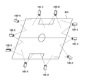
FIG. 1 is a diagram showing an example of the configuration of an imaging system according to this embodiment. The imaging system of this embodiment includes an
撮像装置群100は、m個の撮像装置(撮像装置100-1、100-2、・・・、100-m)を有する。以下、特定の撮像装置を示さない場合、撮像装置100-1、100-2、・・・、100-mを、撮像装置100-xと称する。ここで記載されるm、n(後述)、xは、整数値を示す。
相互に隣り合う位置にある撮像装置100-x同士(例えば、撮像装置100-1と撮像装置100-2)は、伝送ケーブルを介して相互に接続される。撮像装置100-xは、撮像画像や撮像装置100-xの状態情報を画像生成装置200及び情報表示装置300へ伝送する。状態情報については後述する。図1では、撮像装置100-1は、撮像装置100-2と相互に接続される。また、撮像装置100-2は、撮像装置100-1に加え、撮像装置100-2と隣り合う位置にある不図示のもう1つの撮像装置と相互に接続される。そして、撮像装置100-nは、撮像装置100-nと隣り合う位置にある不図示の撮像装置と相互に接続される。また、撮像装置100-nは、HUB400と相互に接続される。つまり、本実施形態のネットワークトポロジはデイジーチェーンである。本実施形態では、こうした接続グループが2つある。もう一つは、撮像装置100-(n+1)から撮像装置100-mまでの撮像装置であり、撮像装置100-(n+1)から撮像装置100-mまでの撮像装置も同様に接続される。接続グループの数は2つに限らず、1つでも3つ以上あってもよい。ネットワークトポロジは、環形(リング型)、メッシュ型、スター型、バス型、ツリー型でもよく、前述の様々な型の複合系でもよく、特に限定されない。
The
Imaging devices 100-x located adjacent to each other (for example, imaging device 100-1 and imaging device 100-2) are connected to each other via a transmission cable. The imaging device 100-x transmits the captured image and state information of the imaging device 100-x to the
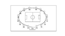
撮像装置100-xは、サッカー場等の競技場や特定の被写体を取り囲むように配置される。図2は、撮像装置100-xの配置の一例を示す図である。図2に示す例では、サッカー場等の競技場210の全て又は一部の範囲が複数の撮像装置100-xで撮像されるように、複数の撮像装置100-xが配置される。
複数の撮像装置100-xは、例えばデジタルカメラであり、外部の不図示の同期装置からの同期信号に基づき、同じタイミングで撮像を行う。撮像装置100-xにより撮像された画像は、伝送ケーブルを介して、HUB400を通り、画像生成装置200、及び、情報表示装置300に伝送される。撮像装置100-xは、静止画像を撮像するカメラであってもよく、動画像を撮像するカメラであってもよく、静止画像及び動画像の双方を撮像するカメラであってもよい。
The imaging devices 100-x are arranged so as to surround a stadium such as a soccer field or a specific subject. FIG. 2 is a diagram showing an example of the arrangement of the imaging devices 100-x. In the example shown in FIG. 2, a plurality of imaging devices 100-x are arranged so that all or part of a
The plurality of imaging devices 100-x are digital cameras, for example, and perform imaging at the same timing based on synchronization signals from an external synchronization device (not shown). An image captured by the imaging device 100-x is transmitted to the
画像生成装置200は、HUB400を介して撮像装置100-xと相互に接続される。画像生成装置200は、撮像装置100-xにより撮像された画像を蓄積する。画像生成装置200は、ユーザ端末の操作に基づいて仮想視点情報が入力された場合、複数の撮像装置100-xにより撮像された画像を用いて、仮想視点情報に対応した仮想視点画像を生成する。仮想視点情報は、位置情報と方向情報とを少なくとも含む。位置情報は、競技場210の中央等の所定位置に対する相対的な位置(例えば、所定位置を基準とした場合の、前後方向、左右方向、及び、上下方向の位置)を示す情報である。方向情報は、その所定位置からの向き(例えば、所定位置を原点とし、前後方向、左右方向、上下方向を軸とする3次元直交座標系での各軸からの角度)を示す情報である。
画像生成装置200は、例えば、サーバ装置であり、撮像装置100-xの画像を保存するデータベース機能や、撮像装置100-xの位置や向きに基づいて仮想視点画像を生成する画像処理機能を有する。画像生成装置200が用いるデータベースは、競技開始前の競技会場の場面等、予め被写体が存在しない状態の競技会場の場面を撮像した画像を、背景画像データとして予め保持する。
The
The
情報表示装置300は、HUB400を介して撮像装置100-xや画像生成装置200と相互に接続される。情報表示装置300は、撮像装置100-xにより撮像された撮像画像や撮像装置100-xの状態情報を受信し、後述する表示画面(表示部508)に表示する。また、画像生成装置200の状態情報も受信し、表示画面に表示する。情報表示装置300には、通常、監視者がつく。監視者は、表示画面に表示された撮像画像等を用いて撮像装置群100や画像生成装置200の状態を定常的に監視する。
HUB400は、撮像装置100-xからの撮像画像を、画像生成装置200及び情報表示装置300に分配する。
The
The
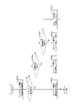
次に、図3を参照して、情報表示装置300の構成の一例について説明する。図3は、情報表示装置300のハードウェア構成の一例を示す図である。
情報表示装置300は、コントローラユニット301と操作ユニット310と表示装置311とを含む。
コントローラユニット301は、CPU302を有する。CPU302は、ROM303に格納されているブートプログラムによりOS(Operating System)を起動する。CPU302は、このOS上で、HDD(Hard Disk Drive)305に格納されているアプリケーションプログラムを実行する。CPU302は、アプリケーションプログラムの実行によって、図7、図8、図11、図13、図20、図21等の各種処理や図4、図19の各種機能等を実現する。CPU302の作業領域としてはRAM304が用いられる。HDD305は、アプリケーションプログラム等を格納する。HDD305は、記憶媒体の一例である。
Next, an example of the configuration of the
The
The
CPU302は、システムバス309を介して、ROM303、RAM304、HDD305、操作部I/F306、表示部I/F307、及び、通信I/F308と相互に接続される。操作部I/F306は、操作ユニット310とのインタフェースである。操作部I/F306は、操作ユニット310によってシステム監視者により入力された情報をCPU302に送出する。操作ユニット310は、例えば、タッチパネル、マウス及びキーボードの少なくとも何れかを有する。表示部I/F307は、表示装置311に表示すべき画像データを表示装置311に対して出力する。表示装置311は、コンピュータディスプレイを有する。コンピュータディスプレイは、液晶パネル又は有機ELパネル等の表示パネル等である。通信I/F308は、伝送ケーブルに接続される。通信I/F308は、伝送ケーブルを介して、外部装置(ユーザ端末やHUB400)との間で情報の入出力を行う。図3で示した構成の全てが情報表示装置300において必須の構成とは限らない。例えば表示装置311は必須の構成ではない。情報表示装置300は、ケーブルやネットワークを介して接続された外部の表示装置に画像を表示させることも可能である。
The
図4は、情報表示装置300の機能構成の一例を示す図である。情報表示装置300は、データ記憶部501とデータ入力・読出部502とUI画像生成部503と状態取得部504と制御部505とユーザ入力部506と制御信号出力部507と表示部508とを有する。これらは、制御部505による制御の下、相互にデータを送受信することができる。図4のデータ記憶部501は図3のHDD305に対応する。図4のデータ入力・読出部502、UI画像生成部503、及び、制御部505は、図3のCPU302に対応する。図4の状態取得部504、及び、制御信号出力部507は、図3の通信I/F308に対応する。図4のユーザ入力部506は、図3の操作部I/F306と操作ユニット310に対応する。図4の表示部508は、表示部I/F307と表示装置311に対応する。以下、各部の構成の一例を詳細に説明する。
FIG. 4 is a diagram showing an example of the functional configuration of the
データ記憶部501は、UI画像生成部503がUIを表示するために必要なデータである撮影環境情報を保持する。撮影環境情報は、少なくとも以下の何れかを含む。
・競技場210のレイアウトデータ
・撮像装置100-xの識別情報
・撮像装置100-xの設置座標情報
・撮像装置100-xの接続先情報
・情報表示装置300の設置座標情報
・情報表示装置300の接続先情報
ここでの設置座標情報は、所定の位置(例えば、競技場210の中央)を原点とした場合のXYZ座標情報である。設置座標情報をXYZ情報とも呼ぶ。接続先情報は、伝送ケーブル(ネットワークケーブル)でどの機器と接続されているかを示す情報である。
A
・Layout data of
図5は、撮影環境情報の内「競技場210のレイアウトデータ」を除くデータ例である。図5には、1台の情報表示装置300と16台の撮像装置100-xの情報が記されている。第1の実施形態の説明には、図5の例を使用する。図5の「Dev」は、装置の識別情報である。情報表示装置300の識別情報はCSである。CSは、制御局(Control Station)の頭文字を取った造語である。撮像装置100-xの識別情報は、2桁の数値からなる。図5の「X、Y、Z」は、情報表示装置300及び撮像装置100-xの設置位置を示す座標値である。図5の座標値の単位は、ミリメートルである。図5の「接続先」は、情報表示装置300及び撮像装置100-xのネットワークの接続先となる装置の識別情報である。例えば、図5では、情報表示装置300であるCSは、HUB400を経由して撮像装置100-01と撮像装置100-02と接続されていることを示す。
データ記憶部501は、情報表示装置300内にある必要はなく、外部の記憶装置にあってもよい。また、撮像装置100-xに関する情報を保持するデータ記憶部501は、各々の撮像装置100-x内にあってもよい。
FIG. 5 shows an example of data excluding "layout data of
The
データ入力・読出部502は、データ記憶部501から各種データを読出し、UI画像生成部503へ出力する。
UI画像生成部503は、データ入力・読出部502から取得したデータと状態取得部504から取得した状態情報とに基づいて、撮像装置100-xを監視するためのUI画像を生成する。UI画像は、複数の撮像装置100-xの状態を表示する画像である。状態情報、及び、UI画像例については後述する。UI画像生成部503は、生成したUI画像を表示イメージとして表示部508に出力して、UI画像を表示装置311に表示するよう制御する。
A data input/
The UI
状態取得部504は、各々の各撮像装置100―xの状態情報を取得し、UI画像生成部503、及び、制御部505へ出力する。UI画像生成部503は、状態情報の変化を検出した場合は、生成したUI画像を更新する。図6は、複数の撮像装置100-xの状態を示す状態情報の一例である。図6の「Dev」は、撮像装置100-xの識別情報である。図6の「Iso」、「Iris」、「Shutter」は、撮像装置100-xに設定されているISO、アイリス、シャッタースピードの値であり、露出に関わる。図6の「Iso」、「Iris」、「Shutter」を露出設定値とも呼ぶ。露出設定値は、撮像パラメータの一例である。図6の「State」は、撮像装置100-xの状態を示す。「State」には、少なくとも以下の4つを含む複数の状態の何れかが設定される。
・Normal
・NW Err
・Vib
・Obstacle
The
・Normal
・NW Err
・Vibs
・Obstacle
「Normal」は、正常を示す。「NW Err」は、ネットワークエラーで、情報表示装置300と撮像装置100-xとの通信ができない状態を示す。ネットワークエラーの原因として、例えば、ネットワークケーブルが非接続、撮像装置100-xの電源がオフといったことが考えられる。「Vib」は、撮像装置100-xが振動していることを示す。撮像装置100-xが振動する原因として、設置時の取り付けの異常、撮像装置自体に外力がかかっているといったことが考えられる。「Obstacle」は、撮像映像内に障害物が映り込んでいる状態を示す。障害物として、観客の身体の一部、荷物等の物体、虫等が考えられる。
"Normal" indicates normal. "NW Err" indicates a state in which communication between the
制御部505は、状態取得部504からの状態情報、又は、ユーザ入力部506からの操作情報に基づき、情報表示装置300の各部に制御指示を出す。例えば、制御部505は、状態取得部504から撮像装置100-xの状態情報を受信すると、撮像装置100-xの露出設定値や状態に基づいてUIイメージ種別を決定し、UI画像生成部503に出力する。UIイメージ種別は、UI画像の画像種別であり、複数の撮像装置100-xの状態の表示形式を示す。また、制御部505は、ユーザ入力部506からUIの切換指示を示す操作情報を取得すると、取得した情報に応じたUIイメージ種別を決定し、UI画像生成部503に出力する。UIイメージ種別は、少なくとも以下を含む。
・配線表示
・パラメータ表示
・実位置表示
The
・Wiring display ・Parameter display ・Actual position display
配線表示は、配線表示UI画像の画像種別である。配線表示UI画像は、情報表示装置300と全ての撮像装置100-xのネットワーク接続構成を表示する画像である。
パラメータ表示は、パラメータ表示UI画像の画像種別である。パラメータ表示UI画像は、複数の撮像装置100-xの撮像パラメータである露出設定値の一覧を表示する画像である。
実位置表示は、実位置表示UI画像の種別である。実位置表示UI画像は、撮像装置100-xの機器自体がスタジアムのどの位置に設置してあるかを表示する画像であり、複数の撮像装置100-xが配置されている位置を地図上に表示する画像である。
UIイメージ種別のより具体的な決定処理、及び、各UI画像の詳細については後述する。
Wiring display is an image type of the wiring display UI image. The wiring display UI image is an image that displays the network connection configuration between the
Parameter display is the image type of the parameter display UI image. The parameter display UI image is an image that displays a list of exposure setting values, which are imaging parameters of a plurality of imaging devices 100-x.
The real position display is a type of real position display UI image. The actual position display UI image is an image that displays where in the stadium the device itself of the imaging device 100-x is installed. This is the image to display.
More specific determination processing of the UI image type and details of each UI image will be described later.
ユーザ入力部506は、操作ユニット310に入力された操作情報を受け付けて、制御部505に出力する。
制御信号出力部507は、制御部505からの制御信号を外部に出力する。出力先は例えば撮像装置100-xである。制御信号には、例えば、ズーム、フォーカス、アイリス、ISO、シャッタースピード、NDフィルタ切換がある。
表示部508は、フレームバッファ、及び、表示パネルを有する。表示部508は、UI画像生成部503から出力された表示イメージをフレームバッファに格納する(上書きする)。そして、表示部508は、フレームバッファに格納した表示イメージを所定のリフレッシュレートで読み出して表示装置311にて表示する。
A
The control
The
(異常内容に応じたUIイメージ種別の決定方法)
図7は、状態取得部504から取得した状態情報に基づいて制御部505がUIイメージ種別を決定するUIイメージ種別決定処理の一例を示すフローチャートである。
S701において、制御部505は、状態取得部504から状態情報を取得する。
S702において、制御部505は、取得した状態情報に基づいて、撮像装置群100に含まれる撮像装置100-xの中に、ネットワークエラーが発生している撮像装置100-xがあるか否かを判定する。より具体的には、制御部505は、図6に示す状態情報の項目「State」が「NwErr」である撮像装置100-xがあるか否かを判定する。制御部505は、ネットワークエラーが発生している撮像装置100-xがあると判定した場合、処理をS703に進める。制御部505は、ネットワークエラーが発生している撮像装置100-xがないと判定した場合、処理をS704に進める。
(Determination method of UI image type according to abnormality content)
FIG. 7 is a flowchart showing an example of UI image type determination processing in which the
In S<b>701 , the
In S702, the
S703において、制御部505は、複数のUIイメージ種別の中から配線表示を選択し、UI画像に使用するUIイメージ種別を配線表示に決定する。
S704において、制御部505は、取得した状態情報に基づいて、撮像装置群100に含まれる撮像装置100-xの中に、露出異常が発生している撮像装置100-xがあるか否かを判定する。制御部505は、次の何れかの場合に、露出異常が発生している撮像装置100-xがあると判定する。第1が、状態情報の項目「Iso」の値が、他の撮像装置100-xの「Iso」の値と異なる撮像装置100-xが1台以上ある場合である。第2が、状態情報の項目「Iris」の値が、他の撮像装置100-xの「Iris」の値と異なる撮像装置100-xが1台以上ある場合である。第3が、状態情報の項目「Shutter」の値が、他の撮像装置100-xの「Shutter」の値と異なる撮像装置100-xが1台以上ある場合である。制御部505は、露出異常が発生している撮像装置100-xがあると判定した場合、処理をS705に進める。制御部505は、露出異常が発生している撮像装置100-xがないと判定した場合、処理をS706に進める。露出異常は、撮像パラメータエラーの一例である。
In step S703, the
In S704, based on the acquired state information, the
S705において、制御部505は、複数のUIイメージ種別の中からパラメータ表示を選択し、UI画像に使用するUIイメージ種別をパラメータ表示に決定する。
S706において、制御部505は、複数のUIイメージ種別の中から実位置表示を選択し、UI画像に使用するUIイメージ種別を実位置表示に決定する。実位置表示が選択される条件は、全ての撮像装置100-xが正常であること、又は、図6に示す項目「State」が「Vib」又は「Obstacle」の撮像装置100-xがあること、である。
S702からS706の処理は、状態情報に基づいて、複数のUIイメージ種別から何れかのUIイメージ種別を決定する第1の決定処理の一例である。本実施形態では、制御部505は、撮像装置100-xのエラーの種別に基づいてUIイメージ種別を決定する。
S707において、制御部505は、決定したUIイメージ種別を表す情報をUI画像生成部503へ出力する。
In step S705, the
In step S706, the
The processing from S702 to S706 is an example of first determination processing for determining one of a plurality of UI image types based on state information. In this embodiment, the
In S<b>707 , the
(配線表示UI画像)
次に、UI画像生成部503が制御部505から取得したUIイメージ種別に応じてUI画像を生成する処理フロー、及び、UI画像の例について説明する。
まず、配線表示UI画像を生成する処理、及び、配線表示UI画像の例について説明する。図8は、配線表示UI画像を生成する処理である配線表示UI画像生成処理の一例を示すフローチャートである。図8の配線表示UI画像生成処理は、図7の処理でUI画像生成部503が制御部505からUIイメージ種別として配線表示を取得した場合に実行される。配線表示UI画像生成処理の各処理が実行される順序は、図8に示す順序に限定されない。図9は、UI画像で表示する撮像装置アイコンの一例である。図10は、配線表示UI画像の一例である。
(Wiring display UI image)
Next, a processing flow in which the UI
First, a process for generating a wiring display UI image and an example of the wiring display UI image will be described. FIG. 8 is a flowchart illustrating an example of wiring display UI image generation processing, which is processing for generating a wiring display UI image. The wiring display UI image generation processing in FIG. 8 is executed when the UI
S801において、UI画像生成部503は、情報表示装置300を表す矩形を描画する。本実施形態での描画は、UI画像用のメモリに図形等の情報を書き込むことでUI画像を生成することを表す。
S802において、UI画像生成部503は、撮影環境情報の接続先情報に基づいて、撮像装置群100に含まれる各々の撮像装置100-xの配線表示UI画像における配置位置を決定する。
In S<b>801 , the UI
In S802, the UI
S803において、UI画像生成部503は、S804又はS805でアイコンの描画が行われていない撮像装置100-xを一つ選択する。そして、UI画像生成部503は、状態取得部504から取得した状態情報に基づいて、選択した撮像装置100-xが異常状態であるか否かを判定する。UI画像生成部503は、選択した撮像装置100-xが異常状態であると判定した場合、処理をS804に進め、異常状態ではないと判定した場合、処理をS805に進める。撮像装置100-xが異常状態とは、選択した撮像装置100-xの図6に示す状態情報の項目「State」が「Normal」以外、又は、選択した撮像装置100-xの露出設定値が異常である場合である。露出設定値が異常とは、撮像装置100-xの「Iris」、「Iso」及び「Shutter」の少なくとも何れかが正常な値ではない場合のことである。「Iris」の正常な値は、例えば、状態情報の「Iris」の値として最も多く使用されている値である。「Iso」の正常な値は、例えば、状態情報の「Iso」の値として最も多く使用されている値である。「Shutter」の正常な値は、例えば、状態情報の「Shutter」の値として最も多く使用されている値である。「Iris」、「Iso」、「Shutter」の正常な値は、予め定められた値でもよい。
In S803, the UI
S804において、UI画像生成部503は、S803で選択した撮像装置100-xを表すアイコンとして図9(b)に示す異常用のアイコンを、S802で決定した配置位置に描画する。
S805において、UI画像生成部503は、S803で選択した撮像装置100-xを表すアイコンとして図9(a)に示す正常用のアイコンを、S802で決定した配置位置に描画する。
S806において、UI画像生成部503は、撮像装置群100に含まれる全ての撮像装置100-xを表すアイコンを描画したか否かを判定する。UI画像生成部503は、全ての撮像装置100-xを表すアイコンを描画したと判定した場合、処理をS807に進め、それ以外の場合、処理をS803に戻す。
In S804, the UI
In S805, the UI
In S806, the UI
S807において、UI画像生成部503は、識別情報を描画する。より具体的には、UI画像生成部503は、撮影環境情報の項目「Dev」を確認し、情報表示装置300の識別情報をS801で描画した矩形内に描画する。また、UI画像生成部503は、撮像装置群100に含まれる撮像装置100-xの識別情報を、S804、及び、S805で描画したアイコンの下に描画する。
S808において、UI画像生成部503は、撮影環境情報の接続先情報に基づいて、伝送ケーブルで接続される装置を表す矩形やアイコンを線で結ぶ。より具体的には、UI画像生成部503は、撮影環境情報の接続先情報に基づいて、情報表示装置300を示す矩形と、情報表示装置300に伝送ケーブルで接続された撮像装置100-xを示すアイコンと、を線で結ぶ。また、UI画像生成部503は、撮影環境情報の接続先情報に基づいて、伝送ケーブルで相互に接続される撮像装置100-xを示すアイコンを線で結ぶ。
以上説明した図8の各ステップの処理での描画によってUI画像生成部503が生成した配線表示UI画像の例を図10に示す。UI画像生成部503は、生成した配線表示UI画像を表示装置311に表示するよう制御する。
In S807, the UI
In step S<b>808 , the UI
FIG. 10 shows an example of a wiring display UI image generated by the UI
(パラメータ表示UI画像)
次に、パラメータ表示UI画像を生成する処理、及び、パラメータ表示UI画像の例について説明する。図11は、パラメータ表示UI画像を生成する処理であるパラメータ表示UI画像生成処理の一例を示すフローチャートである。図11のパラメータ表示UI画像生成処理は、図7の処理でUI画像生成部503が制御部505からUIイメージ種別としてパラメータ表示を取得した場合に実行される。パラメータ表示UI画像生成処理の各処理が実行される順序は、図11に示す順序に限定されない。図12は、パラメータ表示UI画像の一例である。
(Parameter display UI image)
Next, a process for generating a parameter display UI image and an example of the parameter display UI image will be described. FIG. 11 is a flowchart showing an example of parameter display UI image generation processing, which is processing for generating a parameter display UI image. The parameter display UI image generation processing of FIG. 11 is executed when the UI
S1101において、UI画像生成部503は、全ての撮像装置100-xの露出情報及び状態情報を示すためのリストを作成する。UI画像生成部503が作成するリストは、撮影環境情報から検出した撮像装置数分の行があり、列には「Dev」、「Iso」、「Iris」、「Shutter」、「State」がある。
S1102において、UI画像生成部503は、撮影環境情報及び状態情報に基づいて、S1101で作成したリストに値を格納する。UI画像生成部503は、識別情報を表すリストの「Dev」を、データ入力・読出部502から取得した撮影環境情報の「Dev」に基づいて決定する。また、UI画像生成部503は、リストの「Iso」、「Iris」、「Shutter」、状態を表す「State」を、状態取得部504から取得した状態情報に基づいて決定する。
In S1101, the UI
In S1102, the UI
S1103において、UI画像生成部503は、図11の処理が開始してからS1103で異常状態か否かが判定されていない撮像装置100-xを一つ選択する。そして、UI画像生成部503は、状態取得部504から取得した状態情報に基づいて、選択した撮像装置100-xが異常状態であるか否かを判定する。UI画像生成部503は、選択した撮像装置100-xがS803で説明した異常状態であると判定した場合、処理をS1104に進め、異常状態ではないと判定した場合、処理をS1105に進める。
In S1103, the UI
S1104において、UI画像生成部503は、S1103で選択した撮像装置100-xを示すリストの行を異常用セルにする。例えば、UI画像生成部503は、S1103で選択した撮像装置100-xを示すリストの行の各セルを赤色で塗りつぶす。
S1105において、UI画像生成部503は、撮像装置群100に含まれる全ての撮像装置100-xについて異常状態か否かがS1103で判定された場合、処理をS1106に進め、これ以外の場合、処理をS1103に戻す。
S1106において、UI画像生成部503は、パラメータ表示UI画像におけるリスト配置位置を決定する。
以上説明した図11の処理によってUI画像生成部503が生成したパラメータ表示UI画像の例を図12に示す。UI画像生成部503は、生成したパラメータ表示UI画像を表示装置311に表示するよう制御する。
In S1104, the UI
In S1105, if it is determined in S1103 whether or not all the imaging devices 100-x included in the
In S1106, the UI
FIG. 12 shows an example of a parameter display UI image generated by the UI
(実位置表示UI画像)
次に、実位置表示UI画像を生成する処理、及び、実位置表示UI画像の例について説明する。図13は、実位置表示UI画像を生成する処理である実位置表示UI画像生成処理の一例を示すフローチャートである。図13の実位置表示UI画像生成処理は、図7の処理でUI画像生成部503が制御部505からUIイメージ種別として実位置表示を取得した場合に実行される。実位置表示UI画像生成処理の各処理が実行される順序は、図13に示す順序に限定されない。図14は、実位置表示UI画像の一例である。
(Actual position display UI image)
Next, a process for generating a real position display UI image and an example of the real position display UI image will be described. FIG. 13 is a flowchart illustrating an example of real position display UI image generation processing, which is processing for generating a real position display UI image. The real position display UI image generation processing in FIG. 13 is executed when the UI
S1301において、UI画像生成部503は、データ入力・読出部502から取得した競技場210のレイアウトデータを描画する。
S1302において、UI画像生成部503は、データ入力・読出部502から取得した撮影環境情報のXYZ情報に基づいて、情報表示装置300の配置位置を決定し、競技場210の中に情報表示装置300を描画する。
S1303において、UI画像生成部503は、データ入力・読出部502から取得した撮影環境情報のXYZ情報に基づいて、撮像装置群100に含まれる各々の撮像装置100-xの実位置表示UI画像における配置位置を決定する。
図13のS803からS808は、図8のS803からS808と同様である。ただし、図13のS804、S805では、撮像装置100-xの配置位置として、S1303で決定した配置位置を使用する。
In S<b>1301 , the UI
In step S<b>1302 , the UI
In step S1303, the UI
S803 to S808 in FIG. 13 are the same as S803 to S808 in FIG. However, in S804 and S805 of FIG. 13, the arrangement position determined in S1303 is used as the arrangement position of the imaging device 100-x.
以上説明した図13の各ステップの処理での描画によってUI画像生成部503が生成した実位置表示UI画像の例を図14に示す。UI画像生成部503は、生成した実位置表示UI画像を表示装置311に表示するよう制御する。
図8、図11、図13の処理で生成されたUI画像をUI画像生成部503が表示装置311に表示するよう制御する処理は、表示制御処理の一例である。表示制御処理は、状態情報と図7で決定されたUIイメージ種別とに基づいて、複数の撮像装置100-xの状態を表示するよう制御する処理である。本実施形態の表示制御処理では、UI画像生成部503は、状態情報に基づいて、図7の処理で決定されたUIイメージ種別の画像を使用して、複数の撮像装置100-xの状態を表示するよう制御する。
FIG. 14 shows an example of a real position display UI image generated by the UI
The process of controlling the UI
(異常に応じたUI表示切換の効果)
次に、撮像装置100-xの異常に応じたUI画像を切換表示の効果について説明する。図15は、異常発生時の状態情報の一例である。図15の例では、状態取得部504が取得した状態情報において、撮像装置100-11、13、15がネットワークエラーであることを示す。ただし、図5の撮影環境情報に示すように、本実施形態では、撮像装置100-xが数珠つなぎでネットワークケーブル接続されているため、撮像装置100-13、15の異常は撮像装置100-11が異常に影響されたものである。よって、対処すべき機器は撮像装置100-11である。
(Effect of UI display switching according to abnormality)
Next, the effect of switching display of the UI image according to the abnormality of the imaging device 100-x will be described. FIG. 15 is an example of status information when an abnormality occurs. In the example of FIG. 15, the state information acquired by the
図16は、状態情報が図15に示す場合の配線表示UI画像の一例である。図17は、状態情報が図15に示す場合のパラメータ表示UI画像の一例である。図18は、状態情報が図15に示す場合の実位置表示UI画像の一例である。
図16の配線表示UI画像では、システム監視者は、ネットワークの数珠つなぎ接続が一目で分かる。更に、図16の配線表示UI画像では、システム監視者は、ネットワークの末端が全てエラーになっていることから、システム監視者は、撮像装置100-11の異常が原因であることが即確認できる。図17のパラメータ表示UI画像では、システム監視者は、ネットワークエラーが発生していることは検出できるが、接続構成が分からないので、異常の元となる撮像装置100-xの特定ができない。図18の実位置表示UI画像では、システム監視者は、結線を確認することで異常の元となる撮像装置100-xを特定することは可能だが、結線を辿る確認作業が手間であり、配線表示UI画像と比較すると間違いを犯す可能性も高くなる。
本実施形態では、ネットワークエラーが発生した場合、表示装置311に図16のような配線表示UI画像が表示される。したがって、システム監視者は、エラーとなった撮像装置100-xを短時間かつ正確に特定できる。
FIG. 16 is an example of a wiring display UI image when the state information is shown in FIG. FIG. 17 is an example of a parameter display UI image when the state information is shown in FIG. FIG. 18 is an example of an actual position display UI image when the state information is shown in FIG.
In the wiring display UI image of FIG. 16, the system monitor can understand the daisy chain connection of the network at a glance. Furthermore, in the wiring display UI image of FIG. 16, the system monitor can immediately confirm that the abnormality of the imaging device 100-11 is the cause, since all terminals of the network are in error. . In the parameter display UI image of FIG. 17, the system monitor can detect that a network error has occurred, but cannot identify the imaging device 100-x that is the source of the abnormality because he does not know the connection configuration. In the real position display UI image of FIG. 18, the system monitor can identify the imaging device 100-x that is the source of the abnormality by checking the connection. It also increases the chances of making mistakes when compared to the display UI image.
In this embodiment, when a network error occurs, a wiring display UI image as shown in FIG. 16 is displayed on the
次に、撮像装置100-xの露出が異常であった場合について説明する。
情報表示装置300は、撮像装置100-xの露出設定を変更できる。より具体的には、まず、情報表示装置300のユーザ入力部506は、システム監視者等によって指定された撮像装置100-x、及び、この撮像装置100-xに対する露出に関する設定値を受け付ける。次に、制御信号出力部507は、指定された撮像装置100-xに、受け付けた設定値に基づいた制御信号を送信する。これにより、情報表示装置300は、撮像装置100-xの露出設定を変更できる。
したがって、撮像装置100-xの露出が異常の場合、この露出異常を素早く解決するには、異常の撮像装置100-xの特定、及び、Iso、Iris、Shutterの正しい設定値の検出を短時間で行うことにある。この目的に合致するUI画像は、図17のようなパラメータ表示UI画像である。
本実施形態では、露出異常が発生した場合、表示装置311に図17のようなパラメータ表示UI画像が表示される。したがって、システム監視者は、エラーとなった撮像装置100-xを素早く特定でき、露出の設定をすぐに変更することができる。
Next, a case where the exposure of the imaging device 100-x is abnormal will be described.
The
Therefore, when the exposure of the imaging device 100-x is abnormal, in order to quickly solve the exposure abnormality, it is necessary to specify the abnormal imaging device 100-x and detect the correct set values of Iso, Iris, and Shutter for a short time. to do in A UI image that meets this purpose is a parameter display UI image such as that shown in FIG.
In this embodiment, a parameter display UI image as shown in FIG. 17 is displayed on the
最後に、撮像装置100-xの振動を検知した場合、及び、撮像装置100-xの撮影映像に障害物を検知した場合について説明する。振動の要因として、撮像装置100-xの固定する部分の緩み(例えばネジ)や、足場の不安定さ、周辺の振動物の存在が挙げられる。また、撮影映像の障害物の要因として、撮像装置100-xの前にいる観客の身体の映り込み、物体の配置、虫等の飛翔体の映り込みが挙げられる。これらの異常に対処するには、作業者が異常を検出した撮像装置100-xが配置されている場所に行き、人手によって対応する必要がある。したがって、撮像装置100-xの振動を検知した場合、及び、撮像装置100-xの撮影映像に障害物を検知した場合、撮像装置100-xの実際の配置場所が短時間で理解できるUI画像が望ましい。この目的に合致するのが、図18のような実位置表示UI画像である。
本実施形態では、撮像装置100-xの振動を検知した場合、及び、撮像装置100-xの撮影映像に障害物を検知した場合、表示装置311に図18のような実位置表示UI画像が表示される。したがって、システム監視者は、異常の撮像装置100-xの実際の配置場所が素早く分かり、対処を効率的に行うことができる。
Finally, a case where vibration of the imaging device 100-x is detected, and a case where an obstacle is detected in the image captured by the imaging device 100-x will be described. Factors of vibration include looseness (for example, screws) of fixing portions of the imaging device 100-x, unstable footing, and presence of surrounding vibrating objects. Factors that cause obstacles in captured images include the reflection of the body of the spectator in front of the imaging device 100-x, the arrangement of objects, and the reflection of flying objects such as insects. In order to deal with these abnormalities, it is necessary for the operator to go to the place where the imaging device 100-x that detected the abnormality is located and manually deal with it. Therefore, when the vibration of the image capturing device 100-x is detected, and when an obstacle is detected in the image captured by the image capturing device 100-x, the UI image enables the user to understand the actual location of the image capturing device 100-x in a short time. is desirable. A real position display UI image as shown in FIG. 18 meets this purpose.
In the present embodiment, when vibration of the imaging device 100-x is detected, and when an obstacle is detected in the image captured by the imaging device 100-x, a real position display UI image as shown in FIG. 18 is displayed on the
以上説明したように、本実施形態では、情報表示装置300は、撮像装置100-xの異常の内容に応じたUI画像を表示することで、複数の撮像装置100-xの状態を適切に表示できる。そして、システム監視者等は、異常が発生した機器の特定、異常の内容、異常の影響範囲を素早く理解できるとともに、異常に対する適切な対応を素早く行うことができる。なお、本実施形態では、異常の内容に応じて一つのUIイメージ種別が決定される例を示したが、必要に応じて、状態情報に基づいて決定されるUIイメージ種別は複数であってもよい。
As described above, in the present embodiment, the
<第2の実施形態>
次に、第2の実施形態を説明する。第2の実施形態では、撮像装置100-xの設置から撮影までのワークフローに応じてUI画像を切り替えて表示する例を説明する。本実施形態により、ワークフロー実施に好適なUIが表示され、効率良く作業することができる。
本実施形態のワークフローは、複数の撮像装置100-xを撮像システムで使用できるようにする工程を表す。より具体的には、本実施形態のワークフローは、全ての撮像装置100-xの設置から全ての撮像装置100-xが正常に撮像可能な状態にするまでの手順を表す。ワークフローでの作業の進捗状態として、以下の4つがあり、番号の順に遷移する。
1.ネットワーク確認状態
2.設置確認状態
3.露出確認状態
4.撮影可能状態
<Second embodiment>
Next, a second embodiment will be described. In the second embodiment, an example will be described in which UI images are switched and displayed in accordance with the workflow from installation of the imaging device 100-x to shooting. According to this embodiment, a UI suitable for workflow execution is displayed, and work can be performed efficiently.
The workflow of this embodiment represents the process of enabling multiple imaging devices 100-x to be used in an imaging system. More specifically, the workflow of this embodiment represents the procedure from the installation of all the imaging devices 100-x to the state in which all the imaging devices 100-x can normally perform imaging. There are the following four progress states of work in the workflow, and transitions are made in the order of the numbers.
1. Network confirmation state2. 3. Confirmation of installation status. Exposure confirmation state4. Ready to shoot
ネットワーク確認状態は、情報表示装置300と撮像装置100-xとをネットワーク接続する作業が行われていることを表す状態である。ネットワーク確認状態の場合、情報表示装置300は、後述のように、情報表示装置300と全ての撮像装置100-xとのネットワーク接続がされたか否かを確認する。情報表示装置300と全ての撮像装置100-xとのネットワーク接続が確認されると、ワークフローの進捗状態は、設置確認状態へ遷移する。ネットワーク確認状態は、複数の撮像装置100-xの設置から撮像装置100-xのネットワーク接続が正常になるまでの第1の状態の一例である。
The network confirmation state is a state indicating that the network connection between the
設置確認状態は、撮像装置100-xの向きや画角の調整、及び、映像内に障害物がない状態にする作業が行われていることを表す状態である。例えば、設置確認状態での作業では、撮影目標物が撮影映像の中心にあるように撮像装置100-xの向きを調整することや、ズーム・フォーカスの調整、障害物の移動が実施される。設置確認状態での作業は、人の手で撮像装置100-xを調整する作業となる。設置確認状態の場合、情報表示装置300は、後述のように、設置確認状態での作業が完了したか否かを確認する。設置確認状態での作業が完了したことが確認されると、ワークフローの進捗状態は、露出確認状態へ遷移する。設置確認状態は、複数の撮像装置100-xのネットワーク接続が正常になってから複数の撮像装置100-xが正常に設置された状態になるまでの第2の状態の一例である。
The installation confirmation state is a state indicating that work is being performed to adjust the orientation and angle of view of the imaging device 100-x and to ensure that there are no obstacles in the image. For example, in the installation confirmation state, the orientation of the imaging device 100-x is adjusted so that the imaging target is at the center of the captured image, the zoom and focus are adjusted, and obstacles are moved. Work in the installation confirmation state is manual work for adjusting the imaging device 100-x. In the installation confirmation state, the
露出確認状態は、全ての撮像装置100-xの露出設定値を同じ値にする作業が行われていることを表す状態である。露出確認状態の場合、情報表示装置300は、後述のように、全ての撮像装置100-xの露出設定値が同じ値になったか否かを確認する。露出設定値とは、より具体的には、Iso、Iris、Shutterの値である。全ての撮像装置100-xの露出設定値が同じ値になったことが確認されると、ワークフローの進捗状態は、撮影可能状態へ遷移する。露出確認状態は、複数の撮像装置100-xが正常に設置された状態になってから複数の撮像装置100-xの撮像パラメータが正常になるまでの第3の状態の一例である。
撮影可能状態は、撮像システムが撮影可能状態であることを表す状態である。撮影可能状態では、画像生成装置200は、撮像装置100-xが撮影した画像に基づいて、仮想視点画像の生成が可能となる。撮影可能状態は、複数の撮像装置100-xの撮像パラメータが正常であって複数の撮像装置100-xが撮像可能な第4の状態の一例である。
The exposure confirmation state is a state indicating that work is being performed to set the exposure setting values of all the imaging devices 100-x to the same value. In the exposure confirmation state, the
The photographable state is a state indicating that the imaging system is in a photographable state. In the photographable state, the
以下に記載する第2の実施形態の説明では、上記の第1の実施形態と共通する事項について説明を省略し、上記の第1の実施形態と異なる事項についての説明を行う。また、第2の実施形態の説明では、第1の実施形態と同様の構成要素については、第1の実施形態と同じ符号を付しており、その詳細な説明は省略する。 In the description of the second embodiment described below, descriptions of items common to the first embodiment are omitted, and descriptions of items different from the first embodiment are provided. Also, in the description of the second embodiment, the same reference numerals as in the first embodiment are assigned to the same constituent elements as in the first embodiment, and detailed description thereof will be omitted.
図19は、第2の実施形態の情報表示装置300の機能構成の一例を示す図である。情報表示装置300は、データ記憶部501とデータ入力・読出部502とワークフロー管理部1902とUI画像生成部1904と状態取得部1901と制御部1903とユーザ入力部506と制御信号出力部507と表示部508とを有する。これらは、制御部1903による制御の下、相互にデータを送受信することができる。図19のワークフロー管理部1902、制御部1903、UI画像生成部1904は、図3のCPU302に対応する。図19の状態取得部1901は、図3の通信I/F308に対応する。以下、各部の構成の一例を詳細に説明する。
FIG. 19 is a diagram showing an example of the functional configuration of the
状態取得部1901は、撮像装置群100に含まれる撮像装置100―xの状態情報を取得し、ワークフロー管理部1902、UI画像生成部1904、及び、制御部1903へ出力する。
ワークフロー管理部1902は、状態取得部1901から取得した状態情報に基づいてワークフローの進捗状態の管理を行い、ワークフローの進捗状態を更新した場合は制御部1903へワークフロー情報を出力する。
制御部1903は、ワークフロー管理部1902から取得したワークフローの進捗状態に基づいて、UIイメージ種別を決定し、UI画像生成部1904へUIイメージ種別情報を出力する。
UI画像生成部1904は、制御部1903から取得したUIイメージ種別情報と状態取得部504から取得した状態情報とに基づいて、撮像装置100-xを監視するためのUI画像を生成する。UI画像生成部503は、生成したUI画像を表示イメージとして表示部508に出力して、UI画像を表示装置311に表示する。
The
The
The
Based on the UI image type information acquired from the
図20は、ワークフロー管理部1902が、状態取得部1901から取得した状態情報に基づいてワークフローの進捗状態を決定する状態決定処理の一例を示すフローチャートである。状態決定処理は、第2の決定処理の一例である。
S2001において、ワークフロー管理部1902は、状態取得部1901から状態情報を取得する。
S2002において、ワークフロー管理部1902は、HDD305やRAM304に保存したワークフローの現在の進捗状態を確認する。ワークフロー管理部1902は、ワークフローの現在の進捗状態がネットワーク確認状態の場合、処理をS2003に進める。ワークフロー管理部1902は、ワークフローの現在の進捗状態が設置確認状態の場合、処理をS2006に進める。ワークフロー管理部1902は、ワークフローの現在の進捗状態が露出確認状態の場合、処理をS2009に進める。ワークフロー管理部1902は、ワークフローの現在の進捗状態が撮影可能状態の場合、図20の処理を終了する。
FIG. 20 is a flowchart showing an example of state determination processing in which the
In S<b>2001 , the
In step S<b>2002 , the
S2003において、ワークフロー管理部1902は、S2001で取得した状態情報に基づいて、ネットワークエラーが発生している撮像装置100-xがあるか否かを判定する。より具体的には、ワークフロー管理部1902は、図6に示す状態情報の項目「State」が「NwErr」である撮像装置100-xがあるか否かを判定する。ワークフロー管理部1902は、ネットワークエラーが発生している撮像装置100-xがあると判定した場合、処理をS2004に進める。ワークフロー管理部1902は、ネットワークエラーが発生している撮像装置100-xがないと判定した場合、図20の処理を終了する。
S2004において、ワークフロー管理部1902は、ワークフローの進捗状態を設置確認状態に決定する。そして、ワークフロー管理部1902は、ワークフローの進捗状態を設置確認状態に変更して、HDD305やRAM304に保存する。
S2005において、ワークフロー管理部1902は、ワークフローの進捗状態が設置確認状態であることを表す情報を制御部1903に通知する。その後、ワークフロー管理部1902は、図20の処理を終了する。
In S2003, the
In step S2004, the
In step S2005, the
S2006において、ワークフロー管理部1902は、S2001で取得した状態情報に基づいて、状態情報の項目「State」が「Normal」以外の撮像装置100-xがあるか否かを判定する。ワークフロー管理部1902は、「State」が「Normal」以外の撮像装置100-xがあると判定した場合、処理をS2007に進める。ワークフロー管理部1902は、「State」が「Normal」以外の撮像装置100-xがないと判定した場合、図20の処理を終了する。
S2007において、ワークフロー管理部1902は、ワークフローの進捗状態を露出確認状態に決定する。そして、ワークフロー管理部1902は、ワークフローの進捗状態を露出確認状態に変更して、HDD305やRAM304に保存する。
S2008において、ワークフロー管理部1902は、ワークフローの進捗状態が露出確認状態であることを表す情報を制御部1903に通知する。その後、ワークフロー管理部1902は、図20の処理を終了する。
In S2006, based on the state information acquired in S2001, the
In step S2007, the
In step S<b>2008 , the
S2009において、ワークフロー管理部1902は、S2001で取得した状態情報に基づいて、撮像装置群100に含まれる撮像装置100-xの露出設定値が全て同じか否かを判定する。より具体的には、ワークフロー管理部1902は、図6に示す項目「Iso」、「Iris」、「Shutter」ごとの撮像装置100-xの設定値が全て同じ場合、撮像装置群100に含まれる撮像装置100-xの露出設定値が全て同じと判定する。ワークフロー管理部1902は、撮像装置群100に含まれる撮像装置100-xの露出設定値が全て同じと判定した場合、処理をS2010に進め、それ以外の場合、図20の処理を終了する。
In S2009, the
S2010において、ワークフロー管理部1902は、ワークフローの進捗状態を撮影可能状態に決定する。そして、ワークフロー管理部1902は、ワークフローの進捗状態を撮影可能状態に変更して、HDD305やRAM304に保存する。S2004、S2007、S2010の処理は、ワークフローの進捗状態を決定する決定処理の一例である。
S2011において、ワークフロー管理部1902は、ワークフローの進捗状態が撮影可能状態であることを表す情報を制御部1903に通知する。その後、ワークフロー管理部1902は、図20の処理を終了する。
In step S<b>2010 , the
In step S<b>2011 , the
(ワークフローに応じたUIイメージ種別の決定方法)
図21は、制御部1903が、ワークフロー管理部1902から取得したワークフロー情報に基づいてUIイメージ種別を決定するUIイメージ種別決定処理の一例を示すフローチャートである。
S2101において、制御部1903は、ワークフロー管理部1902からワークフローの現在の進捗状態を取得する。
S2102において、制御部1903は、ワークフローの現在の進捗状態がネットワーク確認状態であるか否かを判定する。制御部1903は、現在の進捗状態がネットワーク確認状態であると判定した場合、処理をS2103に進め、現在の進捗状態がネットワーク確認状態ではないと判定した場合、処理をS2104に進める。
S2103において、制御部1903は、複数のUIイメージ種別の中から配線表示を選択し、UI画像に使用するUIイメージ種別を配線表示に決定する。そして、制御部1903は、配線表示を表す情報をUI画像生成部503へ出力する。その後、制御部1903は、図21の処理を終了する。
(Determination method of UI image type according to workflow)
FIG. 21 is a flowchart showing an example of UI image type determination processing in which the
In step S<b>2101 , the
In S2102, the
In S2103, the
S2104において、制御部1903は、ワークフローの現在の進捗状態が設置確認状態であるか否かを判定する。制御部1903は、現在の進捗状態が設置確認状態であると判定した場合、処理をS2105に進め、現在の進捗状態が設置確認状態ではないと判定した場合、処理をS2106に進める。
S2105において、制御部1903は、複数のUIイメージ種別の中から実位置表示を選択し、UI画像に使用するUIイメージ種別を実位置表示に決定する。そして、制御部1903は、実位置表示を表す情報をUI画像生成部503へ出力する。その後、制御部1903は、図21の処理を終了する。
In S2104, the
In S2105, the
S2106において、制御部1903は、ワークフローの現在の進捗状態が露出確認状態であるか否かを判定する。制御部1903は、現在の進捗状態が露出確認状態であると判定した場合、処理をS2107に進め、現在の進捗状態が露出確認状態ではないと判定した場合、処理をS2108に進める。
S2107において、制御部1903は、複数のUIイメージ種別の中からパラメータ表示を選択し、UI画像に使用するUIイメージ種別をパラメータ表示に決定する。そして、制御部1903は、パラメータ表示を表す情報をUI画像生成部503へ出力する。その後、制御部1903は、図21の処理を終了する。
S2108において、制御部1903は、複数のUIイメージ種別の中から全てのUIイメージ種別を選択し、UI画像に使用するUIイメージ種別を全表示に決定する。全表示は、配線表示、パラメータ表示、実位置表示の3つのUI画像を1画面内に表示することを表す。S2108が実行されるのは撮影可能状態であり、システム監視者は、あらゆる情報を網羅的に見ることができるUI表示となる。その後、制御部1903は、図21の処理を終了する。
図21の処理は、図20の処理によって決定された進捗状態に基づいて、複数のUIイメージ種別から何れかのUIイメージ種別を決定する第1の決定処理の一例である。
In S2106, the
In S2107, the
In S2108, the
The processing in FIG. 21 is an example of first determination processing for determining one of a plurality of UI image types based on the progress state determined by the processing in FIG. 20 .
UI画像生成部1904は、制御部1903から取得したUIイメージ種別に基づいて、第1の実施形態と同様にUI画像を生成する。UIイメージ種別が全表示の場合、UI画像生成部1904は、1つの画面に、配線表示UI画像とパラメータ表示UI画像と実位置表示UI画像とを含んだUI画像を生成する。そして、UI画像生成部503は、生成したUI画像を表示装置311に表示するよう制御する。
A UI
以上説明したように本実施形態では、情報表示装置300は、撮像システムのワークフローの進捗状態に応じたUI画像を表示することで、複数の撮像装置100-xの状態を適切に表示できる。したがって、作業者は、撮影が開始できる状態まで効率良く作業を実施することができる。
As described above, in the present embodiment, the
<第3の実施形態>
次に、第3の実施形態を説明する。第3の実施形態では、撮像システムの状態を網羅的に表示しつつ、機器の異常内容に応じて優先的に表示すべき内容を強調して表示する例を説明する。第3の実施形態によって、撮像システム全体を俯瞰して監視しつつ、異常が発生した機器の特定や異常の内容、影響範囲をシステム監視者が素早く理解することができる。
以下に記載する第3の実施形態の説明では、上記の第1の実施形態と共通する事項について説明を省略し、上記の第1の実施形態と異なる事項についての説明を行う。また、第3の実施形態の説明では、第1の実施形態と同様の構成要素については、第1の実施形態と同じ符号を付しており、その詳細な説明は省略する。
<Third Embodiment>
Next, a third embodiment will be described. In the third embodiment, an example will be described in which, while comprehensively displaying the state of the imaging system, the content that should be preferentially displayed is emphasized and displayed according to the abnormality content of the device. According to the third embodiment, the system monitor can quickly understand the identification of the device in which an abnormality has occurred, the content of the abnormality, and the range of influence while monitoring the entire imaging system from a bird's-eye view.
In the description of the third embodiment described below, descriptions of matters common to the first embodiment are omitted, and descriptions of matters different from the first embodiment are given. Further, in the description of the third embodiment, the same reference numerals as in the first embodiment are assigned to the same constituent elements as in the first embodiment, and detailed description thereof will be omitted.
本実施形態では、情報表示装置300はUI画像同時表示機能を搭載し、システム監視者の操作によってUI画像同時表示のオンオフを切り替える機能を有する。UI画像同時表示オンの場合、配線表示UI画像、実位置表示UI画像、パラメータ表示UI画像の3つのUI画像を1画面内に表示する。UI画像同時表示オフの場合は、配線表示UI画像、実位置表示UI画像、パラメータ表示UI画像の内の1つを表示するもので、第1の実施形態と同等である。UI画像同時表示オンの場合のUI画像の表示方法は、第1の表示方法の一例である。UI画像同時表示オフのUI画像の表示方法は、第2の表示方法の一例である。
制御部505は、ユーザ入力部506からの操作情報に基づき、UI画像同時表示オンオフを切り替える。制御部505がユーザ入力部506を介してUI画像同時表示のオン又はオフを受け付ける処理は、受付処理の一例である。
UI画像生成部503は、配線表示UI画像、実位置表示UI画像、パラメータ表示UI画像の3つのUI画像を1画面内に表示し、更にUI画像のサイズを変更し画面上に配置する機能を持つ。
In this embodiment, the
The
The UI
(UIイメージ種別に応じた優先表示内容切換)
制御部505は、図7又は図21と同様の処理で、UIイメージ種別を決定して、制御部505に出力する。UI画像生成部503は、制御部505から取得したUIイメージ種別に基づいて、優先して表示すべきUI画像を決定し、決定したUI画像を他のUI画像より大きいサイズで配置して、表示装置311に表示する。
(Priority display content switching according to UI image type)
The
図22は、UI画像生成部503が制御部505からUIイメージ種別としてパラメータ表示を取得した場合に表示装置311に表示される画面の一例を示す図である。図22のような画面から、システム監視者は、まず、優先して露出調整すべき撮像装置100-xが判断でき、更にどの位置に設置された撮像装置100-xであるかを同時に確認することができる。図22のような画面が有用であるケースとして、例えば撮像装置100-xへの逆光が強く、露出の設定のみでは白飛びが対処できないケースがある。その際は撮像装置100-xの設置位置の移動や、レンズにフィルタを取り付けるといった、実際に撮像装置100-xへ出向いての作業を行う必要がある。この場合は、実際の撮像装置の100-xの配置位置も同時に理解できる方が効率良いので、システム監視者の操作により同時表示オンに設定することが望ましい。
FIG. 22 is a diagram showing an example of a screen displayed on the
以上説明したように、本実施形態では、情報表示装置300は、撮像システムの状態を網羅的に表示しつつ、機器の異常内容に応じて優先的に表示すべき内容を強調して表示することで、複数の撮像装置100-xの状態を適切に表示できる。本実施形態によって、システム監視者等は、撮像システム全体を俯瞰して監視しつつ、異常が発生した機器の特定、異常の内容、異常の影響範囲を素早く理解できる。
As described above, in the present embodiment, the
第3の実施形態では、情報表示装置300は、UI画像同時表示のオンオフを切り替えることができる。しかし、情報表示装置300は、常にUI画像同時表示がオンの状態になるように構成されていてもよい。また、優先して表示すべきUI画像として決定されるUI画像の種別は複数であってもよい。また、情報表示装置300は、全てのUI画像を同じ大きさで表示してもよい。
In the third embodiment, the
(その他の実施形態)
本発明は、上述の実施形態の1以上の機能を実現するプログラムを、ネットワーク又は記憶媒体を介してシステム又は装置に供給し、そのシステム又は装置のコンピュータにおける1つ以上のプロセッサーがプログラムを読出し実行する処理でも実現可能である。また、1以上の機能を実現する回路(例えば、ASIC)によっても実現可能である。
(Other embodiments)
The present invention supplies a program that implements one or more functions of the above-described embodiments to a system or device via a network or a storage medium, and one or more processors in the computer of the system or device reads and executes the program. It can also be realized by processing to It can also be implemented by a circuit (for example, ASIC) that implements one or more functions.
以上、本発明を実施形態と共に説明したが、上記実施形態は本発明を実施するにあたっての具体化の例を示したものに過ぎず、これらによって本発明の技術的範囲が限定的に解釈されてはならないものである。すなわち、本発明はその技術思想、又はその主要な特徴から逸脱することなく、様々な形で実施することができる。
例えば、情報表示装置300のハードウェア構成として、CPUは複数存在してもよく、複数のCPUが各装置のHDD等に記憶されているプログラムに基づき処理を実行するようにしてもよい。また、情報表示装置300のハードウェア構成として、CPUに替えてGPU(Graphics Processing Unit)を用いることとしてもよい。情報表示装置300の機能の一部は、情報表示装置300のハードウェアとして実装されてもよい。また、上記の実施形態を任意に組み合わせてもよい。
As described above, the present invention has been described together with the embodiments, but the above-described embodiments merely show specific examples for carrying out the present invention, and the technical scope of the present invention is not construed in a limited manner. It should not be. That is, the present invention can be embodied in various forms without departing from its technical concept or main features.
For example, as the hardware configuration of the
以上、上述した実施形態によれば、複数の撮像装置100-xの状態を適切に表示できる。 As described above, according to the above-described embodiments, it is possible to appropriately display the states of the plurality of imaging devices 100-x.
100-x 撮像装置
200 画像生成装置
300 情報表示装置
503 UI画像生成部
505 制御部
100-
Claims (14)
前記取得手段によって取得された前記状態情報に基づいて、前記複数の撮像装置の状態の表示形式を示す複数の画像種別から少なくとも一つの画像種別を決定する第1の決定手段と、
前記取得手段によって取得された前記状態情報と前記第1の決定手段によって決定された画像種別とに基づいて、前記複数の撮像装置の状態を表示するよう制御する表示制御手段と、
を有し、
前記複数の画像種別には、少なくとも、前記複数の撮像装置のネットワーク接続構成を表示する形式の第1の画像種別と、前記複数の撮像装置の撮像パラメータの一覧を表示する形式の第2の画像種別と、が含まれ、
前記第1の決定手段は、
前記複数の撮像装置間においてネットワークエラーが発生している場合には、前記第1の画像種別に決定し、
撮像装置のパラメータの異常が発生している場合には、前記第2の画像種別に決定する
表示制御装置。 acquisition means for acquiring state information indicating states of a plurality of imaging devices constituting an imaging system;
a first determining means for determining at least one image type from a plurality of image types indicating a display format of the states of the plurality of imaging devices based on the state information acquired by the acquiring means;
display control means for controlling to display the states of the plurality of imaging devices based on the state information acquired by the acquisition means and the image type determined by the first determination means;
has
The plurality of image types include at least a first image type that displays a network connection configuration of the plurality of imaging devices, and a second image that displays a list of imaging parameters of the plurality of imaging devices. includes a type and a
The first determining means is
if a network error has occurred between the plurality of imaging devices, determining the first image type;
If there is an abnormality in the parameters of the imaging device, the second image type is determined.
Display controller.
前記第1の決定手段は、前記第2の決定手段によって決定された前記進捗状態に基づいて、前記複数の画像種別から少なくとも一つの画像種別を決定する請求項1乃至4何れか1項記載の表示制御装置。 further comprising second determining means for determining a progress state of the step of enabling the plurality of imaging devices to be used in the imaging system based on the status information obtained by the obtaining means;
5. The method according to any one of claims 1 to 4 , wherein said first determining means determines at least one image type from said plurality of image types based on said progress state determined by said second determining means. Display controller.
前記撮影環境情報には、前記複数の撮像装置の設置位置を示す座標値と前記複数の撮像装置のネットワークの接続先の情報とが含まれる請求項1乃至7何れか1項記載の表示制御装置。 The display control means controls to display the states of the plurality of imaging devices based on the state information acquired by the acquisition means and the image type and shooting environment information determined by the first determination means. death,
8. The display control device according to any one of claims 1 to 7 , wherein the shooting environment information includes coordinate values indicating installation positions of the plurality of imaging devices and information on network connection destinations of the plurality of imaging devices. .
前記受付手段によって第1の表示方法の指定が受け付けられた場合、前記表示制御手段は、前記取得手段によって取得された前記状態情報に基づいて、前記第1の決定手段によって決定された画像種別の画像を使用して前記複数の撮像装置の状態を表示するよう制御し、
前記受付手段によって第2の表示方法の指定が受け付けられた場合、前記表示制御手段は、前記取得手段によって取得された前記状態情報に基づいて、前記第1の決定手段によって決定された画像種別の画像が他の画像種別の画像より大きくなるように、前記複数の画像種別の画像を使用して、前記複数の撮像装置の状態を表示するよう制御する請求項1乃至8何れか1項記載の表示制御装置。 further comprising receiving means for receiving designation of a display method,
When the acceptance means accepts the designation of the first display method, the display control means determines the image type determined by the first determination means based on the state information acquired by the acquisition means. controlling to display the status of the plurality of imaging devices using images;
When the acceptance means accepts the specification of the second display method, the display control means determines the image type determined by the first determination means based on the state information acquired by the acquisition means. 9. The method according to any one of claims 1 to 8 , wherein the images of the plurality of image types are used to display the states of the plurality of imaging devices so that the images are larger than the images of other image types. Display controller.
前記取得ステップによって取得された前記状態情報に基づいて、前記複数の撮像装置の状態の表示形式を示す複数の画像種別から少なくとも一つの画像種別を決定する決定ステップと、
前記取得ステップによって取得された前記状態情報と前記決定ステップによって決定された画像種別とに基づいて、前記複数の撮像装置の状態を表示するよう制御する表示制御ステップと、
を含み、
前記複数の画像種別には、少なくとも、前記複数の撮像装置のネットワーク接続構成を表示する形式の第1の画像種別と、前記複数の撮像装置の撮像パラメータの一覧を表示する形式の第2の画像種別と、が含まれ、
前記決定ステップは、
前記複数の撮像装置間においてネットワークエラーが発生している場合には、前記第1の画像種別に決定し、
撮像装置のパラメータの異常が発生している場合には、前記第2の画像種別に決定する
表示制御装置の制御方法。 an obtaining step of obtaining state information indicating the state of a plurality of imaging devices constituting an imaging system;
a determining step of determining at least one image type from a plurality of image types indicating a display format of the states of the plurality of imaging devices based on the state information obtained by the obtaining step;
a display control step of controlling to display the states of the plurality of imaging devices based on the state information obtained by the obtaining step and the image type determined by the determining step;
including
The plurality of image types include at least a first image type that displays a network connection configuration of the plurality of imaging devices, and a second image that displays a list of imaging parameters of the plurality of imaging devices. includes a type and a
The determining step includes:
if a network error has occurred between the plurality of imaging devices, determining the first image type;
If there is an abnormality in the parameters of the imaging device, the second image type is determined.
A control method for a display controller.
Priority Applications (3)
| Application Number | Priority Date | Filing Date | Title |
|---|---|---|---|
| JP2018112723A JP7204351B2 (en) | 2018-06-13 | 2018-06-13 | DISPLAY CONTROL DEVICE, CONTROL METHOD FOR DISPLAY CONTROL DEVICE, AND PROGRAM |
| PCT/JP2019/021989 WO2019239940A1 (en) | 2018-06-13 | 2019-06-03 | Display control apparatus, display control apparatus control method, and program |
| US17/116,556 US11528462B2 (en) | 2018-06-13 | 2020-12-09 | Display control apparatus, method for controlling display control apparatus, and storage medium |
Applications Claiming Priority (1)
| Application Number | Priority Date | Filing Date | Title |
|---|---|---|---|
| JP2018112723A JP7204351B2 (en) | 2018-06-13 | 2018-06-13 | DISPLAY CONTROL DEVICE, CONTROL METHOD FOR DISPLAY CONTROL DEVICE, AND PROGRAM |
Publications (2)
| Publication Number | Publication Date |
|---|---|
| JP2019216363A JP2019216363A (en) | 2019-12-19 |
| JP7204351B2 true JP7204351B2 (en) | 2023-01-16 |
Family
ID=68843369
Family Applications (1)
| Application Number | Title | Priority Date | Filing Date |
|---|---|---|---|
| JP2018112723A Active JP7204351B2 (en) | 2018-06-13 | 2018-06-13 | DISPLAY CONTROL DEVICE, CONTROL METHOD FOR DISPLAY CONTROL DEVICE, AND PROGRAM |
Country Status (3)
| Country | Link |
|---|---|
| US (1) | US11528462B2 (en) |
| JP (1) | JP7204351B2 (en) |
| WO (1) | WO2019239940A1 (en) |
Families Citing this family (1)
| Publication number | Priority date | Publication date | Assignee | Title |
|---|---|---|---|---|
| CN114339067A (en) * | 2021-11-15 | 2022-04-12 | 华能国际电力股份有限公司上海石洞口第二电厂 | Multichannel image and video stream synchronization and distributed processing method and system based on 5G environment |
Citations (3)
| Publication number | Priority date | Publication date | Assignee | Title |
|---|---|---|---|---|
| JP2008131443A (en) | 2006-11-22 | 2008-06-05 | Hitachi Ltd | Monitoring system, and its failure status display method |
| JP2017152827A (en) | 2016-02-23 | 2017-08-31 | ソニー株式会社 | Apparatus management device, apparatus management method and program |
| JP2017212591A (en) | 2016-05-25 | 2017-11-30 | キヤノン株式会社 | Control apparatus, control method, and program |
Family Cites Families (6)
| Publication number | Priority date | Publication date | Assignee | Title |
|---|---|---|---|---|
| US5586254A (en) * | 1992-02-13 | 1996-12-17 | Hitachi Software Engineering Co., Ltd. | System for managing and operating a network by physically imaging the network |
| JP4684317B2 (en) * | 2007-07-23 | 2011-05-18 | 三菱電機株式会社 | Train display management system and train display management method |
| JP2014215828A (en) | 2013-04-25 | 2014-11-17 | シャープ株式会社 | Image data reproduction device, and viewpoint information generation device |
| US10110678B2 (en) * | 2016-08-19 | 2018-10-23 | Sony Corporation | System and method for data communication based on image processing |
| JP6765917B2 (en) * | 2016-09-21 | 2020-10-07 | キヤノン株式会社 | Search device, its imaging device, and search method |
| JP2020517330A (en) * | 2017-04-21 | 2020-06-18 | コーニンクレッカ フィリップス エヌ ヴェKoninklijke Philips N.V. | Pressure contact sensitive patient table for tomographic imaging |
-
2018
- 2018-06-13 JP JP2018112723A patent/JP7204351B2/en active Active
-
2019
- 2019-06-03 WO PCT/JP2019/021989 patent/WO2019239940A1/en active Application Filing
-
2020
- 2020-12-09 US US17/116,556 patent/US11528462B2/en active Active
Patent Citations (3)
| Publication number | Priority date | Publication date | Assignee | Title |
|---|---|---|---|---|
| JP2008131443A (en) | 2006-11-22 | 2008-06-05 | Hitachi Ltd | Monitoring system, and its failure status display method |
| JP2017152827A (en) | 2016-02-23 | 2017-08-31 | ソニー株式会社 | Apparatus management device, apparatus management method and program |
| JP2017212591A (en) | 2016-05-25 | 2017-11-30 | キヤノン株式会社 | Control apparatus, control method, and program |
Also Published As
| Publication number | Publication date |
|---|---|
| JP2019216363A (en) | 2019-12-19 |
| WO2019239940A1 (en) | 2019-12-19 |
| US20210092344A1 (en) | 2021-03-25 |
| US11528462B2 (en) | 2022-12-13 |
Similar Documents
| Publication | Publication Date | Title |
|---|---|---|
| CN110546948B (en) | Display control apparatus, display control method, and storage medium | |
| JP7182865B2 (en) | Display control device, display control method, and program | |
| KR20180075411A (en) | Information processing apparatus and information processing method | |
| US20230209180A1 (en) | Information processing apparatus, method, and non-transitory computer-readable storage medium | |
| JP6381265B2 (en) | Information processing apparatus, display method, and program | |
| JP7204351B2 (en) | DISPLAY CONTROL DEVICE, CONTROL METHOD FOR DISPLAY CONTROL DEVICE, AND PROGRAM | |
| JP7204569B2 (en) | IMAGING DEVICE, SYSTEM, CONTROL METHOD OF IMAGING DEVICE, AND PROGRAM | |
| US11023999B2 (en) | Image processing apparatus, information processing system, information processing method, and storage medium | |
| US10536631B2 (en) | Video display apparatus and control method of video display apparatus | |
| JP2008294789A (en) | Remote instruction system and server device | |
| JP6401480B2 (en) | Information processing apparatus, information processing method, and program | |
| JP2014011566A (en) | Image display apparatus and monitor camera system | |
| JP7462085B2 (en) | Information processing device, method, and program | |
| JP7073120B2 (en) | Video transmitters, information processing devices, systems, information processing methods and programs | |
| JP2020145559A (en) | Information processor, information processing method, and program | |
| US9883103B2 (en) | Imaging control apparatus and method for generating a display image, and storage medium | |
| JP6362090B2 (en) | How to display the preset position of the network camera | |
| CN109688348B (en) | Information processing apparatus, information processing method, and storage medium | |
| JP2017092733A (en) | Camera location assisting device, camera location assisting method, and program | |
| JP2023067619A (en) | Camera control device, camera control method, and program | |
| CN115079712A (en) | Data transmission method, unmanned aerial vehicle, ground station and unmanned aerial vehicle control system | |
| JP2019068389A (en) | Information processing unit, control method and program of information processing unit |
Legal Events
| Date | Code | Title | Description |
|---|---|---|---|
| A621 | Written request for application examination |
Free format text: JAPANESE INTERMEDIATE CODE: A621 Effective date: 20210609 |
|
| A131 | Notification of reasons for refusal |
Free format text: JAPANESE INTERMEDIATE CODE: A131 Effective date: 20220628 |
|
| A521 | Request for written amendment filed |
Free format text: JAPANESE INTERMEDIATE CODE: A523 Effective date: 20220809 |
|
| TRDD | Decision of grant or rejection written | ||
| A01 | Written decision to grant a patent or to grant a registration (utility model) |
Free format text: JAPANESE INTERMEDIATE CODE: A01 Effective date: 20221129 |
|
| A61 | First payment of annual fees (during grant procedure) |
Free format text: JAPANESE INTERMEDIATE CODE: A61 Effective date: 20221228 |
|
| R151 | Written notification of patent or utility model registration |
Ref document number: 7204351 Country of ref document: JP Free format text: JAPANESE INTERMEDIATE CODE: R151 |