JP7193938B2 - Information processing device, its control method, and program - Google Patents
Information processing device, its control method, and program Download PDFInfo
- Publication number
- JP7193938B2 JP7193938B2 JP2018127794A JP2018127794A JP7193938B2 JP 7193938 B2 JP7193938 B2 JP 7193938B2 JP 2018127794 A JP2018127794 A JP 2018127794A JP 2018127794 A JP2018127794 A JP 2018127794A JP 7193938 B2 JP7193938 B2 JP 7193938B2
- Authority
- JP
- Japan
- Prior art keywords
- viewpoint
- virtual
- virtual viewpoint
- input
- point
- Prior art date
- Legal status (The legal status is an assumption and is not a legal conclusion. Google has not performed a legal analysis and makes no representation as to the accuracy of the status listed.)
- Active
Links
Images


Classifications
-
- H—ELECTRICITY
- H04—ELECTRIC COMMUNICATION TECHNIQUE
- H04N—PICTORIAL COMMUNICATION, e.g. TELEVISION
- H04N13/00—Stereoscopic video systems; Multi-view video systems; Details thereof
- H04N13/20—Image signal generators
- H04N13/204—Image signal generators using stereoscopic image cameras
- H04N13/243—Image signal generators using stereoscopic image cameras using three or more 2D image sensors
-
- H—ELECTRICITY
- H04—ELECTRIC COMMUNICATION TECHNIQUE
- H04N—PICTORIAL COMMUNICATION, e.g. TELEVISION
- H04N13/00—Stereoscopic video systems; Multi-view video systems; Details thereof
- H04N13/10—Processing, recording or transmission of stereoscopic or multi-view image signals
- H04N13/106—Processing image signals
- H04N13/111—Transformation of image signals corresponding to virtual viewpoints, e.g. spatial image interpolation
- H04N13/117—Transformation of image signals corresponding to virtual viewpoints, e.g. spatial image interpolation the virtual viewpoint locations being selected by the viewers or determined by viewer tracking
-
- G—PHYSICS
- G06—COMPUTING; CALCULATING OR COUNTING
- G06T—IMAGE DATA PROCESSING OR GENERATION, IN GENERAL
- G06T7/00—Image analysis
- G06T7/20—Analysis of motion
-
- G—PHYSICS
- G06—COMPUTING; CALCULATING OR COUNTING
- G06T—IMAGE DATA PROCESSING OR GENERATION, IN GENERAL
- G06T7/00—Image analysis
- G06T7/70—Determining position or orientation of objects or cameras
-
- H—ELECTRICITY
- H04—ELECTRIC COMMUNICATION TECHNIQUE
- H04N—PICTORIAL COMMUNICATION, e.g. TELEVISION
- H04N13/00—Stereoscopic video systems; Multi-view video systems; Details thereof
- H04N13/10—Processing, recording or transmission of stereoscopic or multi-view image signals
- H04N13/106—Processing image signals
- H04N13/167—Synchronising or controlling image signals
-
- H—ELECTRICITY
- H04—ELECTRIC COMMUNICATION TECHNIQUE
- H04N—PICTORIAL COMMUNICATION, e.g. TELEVISION
- H04N13/00—Stereoscopic video systems; Multi-view video systems; Details thereof
- H04N13/20—Image signal generators
- H04N13/282—Image signal generators for generating image signals corresponding to three or more geometrical viewpoints, e.g. multi-view systems
-
- H—ELECTRICITY
- H04—ELECTRIC COMMUNICATION TECHNIQUE
- H04N—PICTORIAL COMMUNICATION, e.g. TELEVISION
- H04N13/00—Stereoscopic video systems; Multi-view video systems; Details thereof
- H04N13/30—Image reproducers
- H04N13/366—Image reproducers using viewer tracking
- H04N13/383—Image reproducers using viewer tracking for tracking with gaze detection, i.e. detecting the lines of sight of the viewer's eyes
-
- H—ELECTRICITY
- H04—ELECTRIC COMMUNICATION TECHNIQUE
- H04N—PICTORIAL COMMUNICATION, e.g. TELEVISION
- H04N23/00—Cameras or camera modules comprising electronic image sensors; Control thereof
- H04N23/60—Control of cameras or camera modules
-
- H—ELECTRICITY
- H04—ELECTRIC COMMUNICATION TECHNIQUE
- H04N—PICTORIAL COMMUNICATION, e.g. TELEVISION
- H04N23/00—Cameras or camera modules comprising electronic image sensors; Control thereof
- H04N23/80—Camera processing pipelines; Components thereof
Description
本発明は、仮想視点画像の生成に関わる情報処理成装置及びその制御方法に関する。 The present invention relates to an information processing device and a control method for generating a virtual viewpoint image.
昨今、複数のカメラを異なる位置に設置して多視点で同期撮影することにより得られた複数視点画像を用いて仮想視点画像を生成する技術が注目されている。このような仮想視点画像を生成する技術によれば、例えば、サッカーやバスケットボールのハイライトシーンを様々な角度から視聴することが出来、通常の画像と比較してユーザに高臨場感を与えることができる。 2. Description of the Related Art Recently, attention has been paid to a technique of generating a virtual viewpoint image using multi-viewpoint images obtained by installing a plurality of cameras at different positions and performing multi-viewpoint synchronous photography. According to the technology for generating such virtual viewpoint images, for example, highlight scenes of soccer or basketball can be viewed from various angles, and compared to normal images, the user can be given a high sense of realism. can.
複数視点画像に基づく仮想視点画像は、複数のカメラが撮影した画像をサーバなどの画像処理部に集約し、当該画像処理部にて、3次元モデル生成、レンダリングなどの処理を施すことで生成される。このような仮想視点画像の生成では、仮想視点の設定が必要であり、例えばコンテンツ制作者は、仮想視点の位置を時刻の経過とともに移動させることで仮想視点画像を生成する。ある単一の時刻の画像についても、視聴者の好み・嗜好により様々な仮想視点が要求されうる。特許文献1では、複数視点画像と、推奨される仮想視点を示すメタデータを含む自由視点画像データを生成する。ユーザは、自由視点画像データに含まれているメタデータを用いることで様々な仮想視点を容易に設定することができる。 A virtual viewpoint image based on a multi-viewpoint image is generated by collecting images taken by multiple cameras in an image processing unit such as a server, and performing processing such as 3D model generation and rendering in the image processing unit. be. Generation of such a virtual viewpoint image requires setting of a virtual viewpoint. For example, a content creator generates a virtual viewpoint image by moving the position of the virtual viewpoint over time. Various virtual viewpoints may be required for an image at a single time as well, depending on the preferences and preferences of the viewer. In Patent Document 1, multi-viewpoint images and free-viewpoint image data including metadata indicating recommended virtual viewpoints are generated. The user can easily set various virtual viewpoints by using the metadata included in the free viewpoint image data.
好みの異なる複数の視聴者に仮想視点画像を提供する場合や、視聴者がある視点の仮想視点画像と別視点の仮想視点画像の両方を見たい場合などでは、同時刻における複数の仮想視点に対応する複数の仮想視点画像が生成される。しかしながら、従来のように、複数の仮想視点画像を生成するために複数の時系列的な仮想視点を個別に設定すると、仮想視点の設定に多大な時間を費やしてしまう。特許文献1の技術を用いれば、単一の仮想視点を設定するための手間は軽減されるが、複数の仮想視点を設定する場合には依然としてその設定のための手間が増大する。 When providing virtual viewpoint images to multiple viewers with different tastes, or when viewers want to see both a virtual viewpoint image from a certain viewpoint and a virtual viewpoint image from a different viewpoint, multiple virtual viewpoint images at the same time can be used. A corresponding plurality of virtual viewpoint images are generated. However, if a plurality of time-series virtual viewpoints are individually set in order to generate a plurality of virtual viewpoint images as in the conventional art, setting the virtual viewpoints takes a lot of time. Using the technique of Patent Literature 1 reduces the effort required to set a single virtual viewpoint, but still increases the effort required to set a plurality of virtual viewpoints.
本発明は、このような課題に鑑みてなされたものであり、仮想視点画像の生成に係る複数の仮想視点を容易に設定できるようにすることを目的とする。 SUMMARY OF THE INVENTION The present invention has been made in view of such problems, and an object of the present invention is to facilitate setting of a plurality of virtual viewpoints for generating a virtual viewpoint image.
本発明の一態様による情報処理装置は以下の構成を有する。すなわち、
複数の撮影装置の撮影により得られる複数の画像に基づく仮想視点画像の生成に係る、ユーザによって指定される第1仮想視点を設定する設定手段と、
前記設定手段により設定された前記第1仮想視点からの視線方向に基づいて前記第1仮想視点の注視点を特定する特定手段と、
前記注視点を通る回転軸により前記第1仮想視点を所定角度だけ回転した位置に配置され、前記注視点を注視点とする第2仮想視点であって、前記複数の撮影装置の撮影期間における前記第1仮想視点と共通の時刻に対応する第2仮想視点を特定するための視点情報を、生成する生成手段と、を有する。
An information processing apparatus according to one aspect of the present invention has the following configuration . i.e.
setting means for setting a first virtual viewpoint specified by a user for generating a virtual viewpoint image based on a plurality of images obtained by photographing by a plurality of photographing devices;
specifying means for specifying a gaze point of the first virtual viewpoint based on the line-of-sight direction from the first virtual viewpoint set by the setting means ;
a second virtual viewpoint arranged at a position obtained by rotating the first virtual viewpoint by a predetermined angle about a rotation axis passing through the point of interest, and having the point of interest as the point of interest ; and generating means for generating viewpoint information for specifying a second virtual viewpoint corresponding to a time common to the first virtual viewpoint.
本発明によれば、仮想視点画像の生成に係る複数の仮想視点を容易に設定することができる。 According to the present invention, it is possible to easily set a plurality of virtual viewpoints for generating a virtual viewpoint image.
以下、添付の図面を参照して本発明の実施形態のいくつかを説明する。なお、本明細書において、画像とは「映像」「静止画」「動画」を総称する用語である。 Some embodiments of the present invention will now be described with reference to the accompanying drawings. In this specification, the term "image" is a general term for "video", "still image", and "moving image".
<第1実施形態>
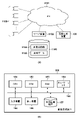
図11(a)は、第1実施形態による仮想視点画像生成システムの構成例を示すブロック図である。図11(a)において、ローカルエリアネットワーク(LAN1101)に複数のカメラ1100が接続されている。サーバ1102は、LAN1101を介して複数のカメラ1100により取得される複数の画像を、多視点画像1104として記憶装置1103に格納する。また、サーバ1102は、仮想視点画像を生成するための素材データ1105(3次元オブジェクトモデル、3次元オブジェクトの位置、テクスチャなどを含む)を多視点画像1104から生成し、記憶装置1103に格納する。画像生成装置100は、LAN1101を介してサーバ1102から素材データ1105(必要に応じて多視点画像1104)を取得し、仮想視点画像を生成する。
<First embodiment>
FIG. 11A is a block diagram showing a configuration example of the virtual viewpoint image generation system according to the first embodiment. In FIG. 11(a), a plurality of
図11(b)は画像生成装置100として用いられる情報処理装置のハードウェア構成例を示すブロック図である。画像生成装置100において、CPU151はメインメモリとしてのROM152またはRAM153に記憶されているプログラムを実行することにより、画像生成装置100における種々の処理を実現する。ROM152は読み出し専用の不揮発性メモリ、RAM153は随時に読み書きが可能な揮発性メモリである。ネットワークI/F154は、LAN1101と接続して、例えばサーバ1102との通信を実現する。入力装置155は、キーボードやマウス等の装置であり、ユーザからの操作入力を受け付ける。表示装置156は、CPU151の制御下で各種の表示を行う。外部記憶装置157は、例えばハードディスクやシリコンディスク等の不揮発性メモリで構成され、各種データ、プログラムを格納する。バス158は上述の各部を接続し、データ転送を行う。
FIG. 11B is a block diagram showing a hardware configuration example of an information processing device used as the
図1は、第1実施形態の画像生成装置100の機能構成例を示すブロック図である。なお、図1に示される各部は、CPU151が所定のプログラムを実行することで実現されてもよいし、専用のハードウェアにより実現されてもよいし、ソフトウェアとハードウェアの協働により実現されてもよい。
FIG. 1 is a block diagram showing a functional configuration example of an
視点入力部101は、仮想カメラを設定するための仮想視点のユーザ入力を受け付ける。以下、視点入力部101が受けつけた入力により指定される仮想視点を入力視点と称する。入力視点を指定するためのユーザ入力は入力装置155を介してなされる。別視点生成部102は、ユーザが指定した入力視点に基づいて、別の仮想カメラの位置を設定するための、入力視点とは別の仮想視点を生成する。以下、別視点生成部102が生成する仮想視点を別視点と称する。素材データ取得部103は、サーバ1102から、仮想視点画像を生成するための素材データ1105を取得する。仮想視点画像生成部104は、素材データ取得部103で取得した素材データを用いて、視点入力部101からの入力視点と別視点生成部102からの別視点を元に、それぞれの仮想視点に対応した仮想視点映像を生成する。表示制御部105は、素材データ取得部103が取得した素材データの画像(例えば、多視点画像1104のうちの1つの画像)や仮想視点画像生成部104が生成した仮想視点画像を、表示装置156に表示するための制御を行う。データ記憶部107は、外部記憶装置157を用いて、仮想視点画像生成部104が生成した仮想視点画像や視点入力部101もしくは別視点生成部102から送られた視点の情報などを記憶する。なお、画像生成装置100の構成は図1に示すものに限定されない。例えば、視点入力部101及び別視点生成部102が画像生成装置100とは別の情報処理装置に実装されていてもよい。
A
図2は、仮想視点(仮想カメラ)の配置例を示した模式図である。図2では、例えばサッカーの試合における攻撃側の選手、防御側の選手、仮想カメラの位置関係が示されている。図2(a)は選手、ボール、仮想カメラの配置を横から見た図であり、図2(b)は選手、カメラ、ボールを真上から俯瞰した図である。図2において、攻撃者201は、ボール202を操っている。防御者203は、攻撃者201の攻撃を防ごうとしている相手チームの選手であり、攻撃者201に対峙している。仮想カメラ204は、ユーザ(例えば、コンテンツ制作者)が設定した入力視点211に対応した仮想カメラであり、攻撃者201の後方に配置されて攻撃者201から防御者203の方向に向いている。入力視点211(仮想カメラ204)の視点情報として、仮想カメラの位置、方向、姿勢、画角などが設定されるがこれに限定されない。例えば、仮想カメラの位置と注視点の位置を指定することにより仮想カメラの方向が設定されるようにしてもよい。
FIG. 2 is a schematic diagram showing an arrangement example of virtual viewpoints (virtual cameras). FIG. 2 shows, for example, the positional relationship between an attacking player, a defending player, and a virtual camera in a soccer match. FIG. 2(a) is a side view of the layout of the players, the ball, and the virtual camera, and FIG. 2(b) is a top view of the players, the camera, and the ball. In FIG. 2, an
仮想カメラ205は、入力視点211に基づいて設定された別視点212に対応した仮想カメラであって、仮想カメラ204に対峙するように配置されている。図2の例では、仮想カメラ205は、防御者203の後方に配置されており、カメラ視線の方向は、防御者203から攻撃者201の方向となっている。仮想カメラ204は、コンテンツ制作者が手動により、例えばカメラ位置・姿勢を決定するパラメータを入力したことによって設定された入力視点211に基づいて配置されたものである。一方、別視点212(仮想カメラ205)は、入力視点211(仮想カメラ204)を配置したことにより、別視点生成部102が自動的に配置したものである。また、注視点206は、仮想カメラ204、205のそれぞれのカメラの視線が地面と交わる点である。本実施形態では、入力視点211の注視点と別視点212の注視点は共通している。
The
図2(a)において、入力視点211と攻撃者201との距離はh1である。また入力視点211及び別視点212の地面からの高さはh2である。また入力視点211及び別視点212のそれぞれから地面におろした垂線の位置と注視点206との距離はh3である。別視点212の視点位置および視線方向は、入力視点211を、注視点206を通る垂線213を軸として180度回転した位置となっている。
In FIG. 2A, the distance between the
図3(a)は、図2で示した入力視点211と別視点212の軌跡を表した図である。入力視点211の軌跡(カメラパス)は、A1、A2、A3、A4、A5の各地点を通る曲線301であり、別視点212の軌跡(カメラパス)は、B1、B2、B3、B4、B5の各地点を通る曲線302である。図3(b)は、横軸に時間を取り、各時刻における入力視点211と別視点212の位置を示した図である。時間T1からT5の各時間において、入力視点211は、A1からA5、別視点212は、B1からB5の位置にあることを示している。従って、例えば、A1とB1はそれぞれ同時刻T1における入力視点211と別視点212の位置を表している。
FIG. 3A is a diagram showing the trajectories of the
図3(a)において、地点A1とB1、地点A2とB2、地点A3とB3、地点A4とB4、地点A5とB5を結ぶ直線の方向は、時間T1からT5における入力視点211と別視点212のそれぞれの視線方向を表している。すなわち、本実施形態では、2つの仮想視点(仮想カメラ)は各時刻において常に向かい合う方向に視線が向いており、2つの仮想視点間の距離も同じである。各時刻における入力視点211と別視点212の間の距離は常に等しくなるように設定されている。
In FIG. 3A, the directions of straight lines connecting points A1 and B1, points A2 and B2, points A3 and B3, points A4 and B4, and points A5 and B5 are the
次に、別視点生成部102の動作について説明する。図4(a)は、視点入力部101および別視点生成部102が視点情報を取得する処理を示すフローチャートである。ステップS401において、視点入力部101は、コンテンツ制作者により入力視点211の視点情報が入力されたか否かを判定する。ステップS401で視点情報が入力されたと判定されると、処理はステップS402へ進む。ステップS402において、視点入力部101は、入力視点211の視点情報を別視点生成部102と仮想視点画像生成部104に提供する。ステップS403において、別視点生成部102は、入力視点の視点情報に基づいて、別視点を生成する。例えば、別視点生成部102は、図2で説明したように、入力視点211に基づいて別視点212を生成し、その視点情報を生成する。ステップS404において、別視点生成部102は、生成した別視点の視点情報を仮想視点画像生成部104に提供する。ステップS405において、別視点生成部102は、視点入力部101からの視点情報の受信が終了しているか否かを判断する。視点情報の受信が終了していると判断された場合、本フローチャートを終了し、引き続き視点情報を受信していると判断された場合、処理はステップS401に戻る。
Next, the operation of the different-
以上の処理により、別視点生成部102は、視点入力部101から時系列に入力される入力視点に追従して時系列に別視点を生成する。例えば、図3(a)に示す曲線301を描くように移動していく入力視点211が入力されると、別視点生成部102はこれに追従して曲線302を描くように別視点212を生成していく。仮想視点画像生成部104は、視点入力部101からの視点情報と別視点生成部102からの別視点情報により、それぞれの仮想視点画像を生成する。
Through the above processing, the different
次に、仮想視点画像生成部104による仮想視点画像の生成処理について説明する。図4(b)は、仮想視点画像生成部104が、仮想視点画像を生成する処理を示すフローチャートである。ステップS411において、仮想視点画像生成部104は、視点入力部101から入力視点211の視点情報を受け取ったかどうかを判定する。ステップS411で視点情報を受け取ったと判定された場合、処理はステップS412に進み、受け取っていないと判定された場合、処理はステップS411に戻る。ステップS412において、仮想視点画像生成部104は、受信した視点情報を元に仮想カメラ204を配置し、仮想カメラ204により撮影される仮想視点画像を生成する。
Next, the virtual viewpoint image generation processing by the virtual viewpoint
ステップS413において、仮想視点画像生成部104は、別視点生成部102から別視点212の視点情報を受け取ったかどうかを判定する。ステップS413で別視点212の視点情報を受け取ったと判定された場合、処理はステップS414に進み、受け取っていないと判定された場合、処理はステップS413に戻る。ステップS414において、仮想視点画像生成部104は、ステップS413で受信した視点情報を元に仮想カメラ205を配置し、仮想カメラ205により撮影される仮想視点画像を生成する。ステップS415において、仮想視点画像生成部104は、視点入力部101、別視点生成部102の各部からの視点情報を受信し終わったか否かを判定する。視点情報の受信を完了したと判定された場合、本フローチャートの処理は終了し、視点情報の受信を完了していないと判定された場合、処理はステップS411に戻る。
In step S<b>413 , the virtual viewpoint
尚、図4(b)のフローチャートでは、仮想視点画像を生成する処理であるステップS412とステップS414を時系列に行うが、これに限定されない。複数の仮想視点に対応して複数の仮想視点画像生成部104を設けて、ステップS412とステップS414における仮想視点画像の生成処理を並行して行うようにしてもよい。なお、ステップS412で生成される仮想視点画像は仮想カメラ204から撮影可能な画像であり、同様に、ステップS404で生成される仮想視点画像は仮想カメラ205から撮影可能な画像である。
Note that in the flowchart of FIG. 4B, steps S412 and S414, which are processes for generating a virtual viewpoint image, are performed in time series, but the present invention is not limited to this. A plurality of virtual viewpoint
次に、これら入力視点211(仮想カメラ204)に対する別視点212(仮想カメラ205)の生成(ステップS403)について、図2および図3を用いてさらに説明する。本実施形態では、コンテンツ制作者が1つの入力視点211を指定すると、その入力視点211に基づき、所定の法則により別視点212が設定される。所定の法則の一例として、本実施形態では、入力視点211と別視点212で共通の注視点206を用い、注視点206を通る垂線213を回転軸として、入力視点211を所定角度だけ回転することにより別視点212を生成する構成を示す。
Next, generation (step S403) of another viewpoint 212 (virtual camera 205) for these input viewpoints 211 (virtual camera 204) will be further described with reference to FIGS. 2 and 3. FIG. In this embodiment, when the content creator designates one
入力視点211は、攻撃者201から距離h1だけ後方で高さが攻撃者201よりも高いh2の高さにコンテンツ制作者によって配置されている。また、入力視点211の視線方向は、時間T1において防御者203の方向を向いている。本実施形態では、入力視点211の視線と地面との交点が注視点206となっている。一方、時刻T1における別視点212は、図4のステップS403において、別視点生成部102により生成される。本実施形態では、別視点生成部102は、入力視点211の位置を、注視点206を通る地面に垂直な線である垂線213を回転軸として所定角度(本実施形態では180度)回転することにより別視点212を得る。結果、注視点206から距離h3、高さh2の3次元範囲に別視点212が配置される。
The
尚、本実施形態では注視点206が地面にあるように設定されているがこれに限定されない。例えば、入力された視線情報により示される入力視点211の視線方向が地面と平行であった場合、その注視点は、注視点206を通る垂線213上の高さがh2の点とすることができる。別視点生成部102は、入力視点と別視点との間の距離と視線方向の関係とを維持するように、時系列に設定される入力視点に応じて別視点を生成する。よって、入力視点211に対する別視点212の生成方法は上記に限られるものではなく、例えば入力視点211の注視点と別視点212の注視点は個別に設定されてもよい。
In this embodiment, the
図3(a)の例では、時間T1から時間経過した際の入力視点211の軌跡が曲線301で表されており、時間T2、T3、T4、T5における入力視点211の位置(仮想カメラ204の位置)はそれぞれA2、A3、A4、A5である。同様に、時間T2、T3、T4、T5における別視点212の位置(仮想カメラ205の位置)はそれぞれ曲線302上のB2、B3、B4、B5である。入力視点211と別視点212の位置関係は、時刻T1における正対した状態が維持され、それぞれの時刻において注視点206を通る垂線213に対して対称な位置に配置されている。時間T1からT5においてはどの時間を切り取っても上記位置関係が成り立つように別視点212の位置(仮想カメラ205の位置)を、ユーザ入力により設定された入力視点211を元に自動で配置される。もちろん、別視点の位置は上記位置関係に限らず、また別視点の数も1つに限定されない。
In the example of FIG. 3A, the trajectory of the
また、第1実施形態では、コンテンツ制作者が作製した入力視点211の視点情報(視点位置、視線方向など)を元に、注視点206を通る垂線213を軸として180度回転させた位置に仮想カメラ205を配置したが、これに限られるものではない。図2において、別視点212の位置を決定する視点の高さ(h2)、水平方向の位置(h3)および視線方向のそれぞれのパラメータを特定の法則によって変更したものでも良い。例えば、別視点212の高さ、注視点206からの距離は、入力視点211の高さ、距離と異なっていてもよい。また、垂線213を軸として入力視点211を120度ずつ回転させた位置にそれぞれ別視点を配置しても構わない。また、入力視点と同じ位置で、姿勢および/または画角が異なるように別視点を生成してもよい。
In the first embodiment, based on the viewpoint information (viewpoint position, line-of-sight direction, etc.) of the
以上のように、第1実施形態によれば、仮想視点画像を生成する際に、ユーザ操作による入力視点を設定することで、入力視点とは位置及び向きの少なくとも何れかが異なる別視点が自動的に設定される。そのため、第1実施形態によれば、共通の時刻における複数の仮想視点に応じた複数の仮想視点画像を容易に得ることができる。 As described above, according to the first embodiment, when generating a virtual viewpoint image, by setting an input viewpoint by user operation, another viewpoint that is different from the input viewpoint in at least one of position and orientation is automatically generated. is set Therefore, according to the first embodiment, it is possible to easily obtain a plurality of virtual viewpoint images corresponding to a plurality of virtual viewpoints at a common time.
<第2実施形態>
第1実施形態では、ユーザにより設定された入力視点(例えば仮想カメラ204を配置する視点)に基づいて、別視点(例えば仮想カメラ205を配置する視点)が自動的に設定される構成を説明した。第2実施形態では、オブジェクトの位置を用いて別視点を自動的に設定する。なお、第2実施形態による仮想視点画像生成システム、画像生成装置100のハードウェア構成および機能構成は第1実施形態(図11(a)、図11(b)、図1)と同様である。ただし、別視点生成部102は、素材データ取得部103から素材データを受け取ることが可能になっている。
<Second embodiment>
In the first embodiment, a configuration has been described in which another viewpoint (for example, the viewpoint for arranging the virtual camera 205) is automatically set based on the input viewpoint (for example, the viewpoint for arranging the virtual camera 204) set by the user. . In the second embodiment, another viewpoint is automatically set using the position of the object. The hardware configuration and functional configuration of the virtual viewpoint image generation system and
図5は、サッカーの試合を模した概略図であり、視点(仮想カメラ)の配置を示すべくサッカーフィールドを真上から俯瞰した図である。図5において、白い四角で表したオブジェクトとハッチングで表したオブジェクトがサッカー選手であり、ハッチングの有無により所属するチームが示されている。図5では、選手Aがボールを保持している状態が示されている。選手Aの後方(ボールが存在する位置の反対側)にコンテンツ制作者によって入力視点211が設定され、これに基づいた仮想カメラ501が設置されている。選手Aの周りには敵味方の選手B~Gが位置している。選手Bの後方に別視点212a(仮想カメラ502)が、選手Fの後方に別視点212b(仮想カメラ503)が、また選手AからGの全員を横から俯瞰できる場所に別視点212c(仮想カメラ504)が配置されている。なお、選手B,Fの入力視点211側を前方、反対側を後方と呼んでいる。
FIG. 5 is a schematic diagram simulating a soccer match, and is a view looking down on a soccer field from directly above to show the arrangement of viewpoints (virtual cameras). In FIG. 5, objects represented by white squares and objects represented by hatching are soccer players, and the team to which they belong is indicated by the presence or absence of hatching. FIG. 5 shows a state in which player A is holding the ball. An
図6(a)は図5を立体的に表した図である。図6(a)では、サッカーフィールドの四隅のうちの1つを3次元座標の原点とし、サッカーフィールドの長手方向をx軸、短手方向をy軸、高さ方向をz軸と定義している。また、図6(a)においては、図5で示した選手のうち選手A、選手Bのみを記載し、図5に示した視点(仮想カメラ)のうち、入力視点211(仮想カメラ501)と別視点212a(仮想カメラ502)が示されている。図6(b)は、図6(a)で示した入力視点211、別視点212aの視点情報を表した図である。入力視点211の視点情報は、視点位置の座標(x1,y1,z1)、注視点位置の座標(x2,y2,z2)を含む。また、別視点212aの視点情報は、視点位置の座標(x3,y3,z3)、注視点位置の座標(x4,y4,z4)を含む。
FIG. 6(a) is a diagram showing FIG. 5 three-dimensionally. In FIG. 6A, one of the four corners of the soccer field is defined as the origin of the three-dimensional coordinates, the longitudinal direction of the soccer field is defined as the x-axis, the lateral direction as the y-axis, and the height direction as the z-axis. there is 6A shows only players A and B among the players shown in FIG. 5, and of the viewpoints (virtual cameras) shown in FIG. Another
図7は図5に示した俯瞰図に対して、入力視点211(仮想カメラ501)、別視点212a(仮想カメラ502)のそれぞれの視点位置、注視点位置の3次元座標(図6(b))をプロットしたものである。入力視点211(仮想カメラ501)は選手Aとボールを結ぶ方向に向いており、別視点212a(仮想カメラ502)は選手Bから選手Aを結ぶ方向を向いている。
FIG. 7 shows three-dimensional coordinates (FIG. 6(b)) of viewpoint positions and gaze positions of the input viewpoint 211 (virtual camera 501) and another
図8は、第2実施形態の別視点生成部102による、別視点212aの生成処理を示したフローチャートである。ステップS801において、別視点生成部102は、視点入力部101から入力視点211の視点情報を受信したかどうかを判断する。ステップS801において、視点情報を受信したと判断された場合、処理はステップS802に進み、視点情報を受信していないと判断された場合、処理はステップS801を繰り返す。ステップS802において、別視点生成部102は、素材データ取得部103から、素材データに含まれる選手A~Gの座標(オブジェクトの座標)を取得したかどうかを判断する。素材データを取得していると判断された場合、処理はステップS803に進み、取得していないと判断された場合、処理はステップS802を繰り返す。
FIG. 8 is a flow chart showing the generation processing of the another
ステップS803において、別視点生成部102は、ステップS801で取得した視点情報と、S802で取得した素材データ(オブジェクトの座標)を元に、仮想カメラ502の視点位置及び注視点位置(別視点)を生成する。ステップS804において、別視点生成部102は、視点入力部101からの視点情報の受信が終了しているか否かを判断する。視点情報の受信が終了していると判断された場合、本フローチャートを終了し、引き続き視点情報を受信していると判断された場合、処理はステップS801に戻る。
In step S803, the separate
ここで、ステップS803における、別視点の生成について詳述する。図7に示すように、コンテンツ制作者によって設定された入力視点211は選手Aの後方で座標(x1,y1,z1)に位置しており、入力視点211の注視点位置の座標は(x2,y2,z2)である。入力視点211について設定された視線方向の視線が所定高さの平面(例えば地面)と交差する位置を注視点206とする。或は、コンテンツ制作者が注視点206aを指定することに応じて、入力視点211と注視点206を結ぶように視線方向が設定されてもよい。本実施形態の別視点生成部102は、多視点画像1104に含まれている2つのオブジェクト(本例では、選手Aと選手B)の位置関係に基づいて別視点を生成する。本実施形態では、そのようにして生成された別視点を初期視点として決定した後、一方のオブジェクト(選手A)に対する位置と視線方向の関係を維持するように、別視点をオブジェクト(選手A)の位置に追従させる。
Here, generation of another viewpoint in step S803 will be described in detail. As shown in FIG. 7, the
次に、初期視点の決定方法を説明する。まず、別視点生成部102は、視点入力部101から、視点位置の座標(x1,y1,z1)と注視点位置の座標(x2,y2,z2)を含む入力視点211の視点情報を得る。次に、別視点生成部102は、素材データ取得部103より、各選手の位置座標(素材データのうちのオブジェクト位置の情報)を得る。例えば選手Aの位置座標は(xa,ya,za)である。なお、選手Aの位置座標の高さ方向の値zaは、例えば選手の顔の中心の高さ、身長などを用いることができる。ただし、身長を用いる場合は、各選手の身長があらかじめ登録されているものとする。
Next, a method for determining the initial viewpoint will be described. First, the different
本実施形態では別視点212a(仮想カメラ502)が選手Bの後方に生成される。別視点生成部102は、入力視点211に最も近い選手Aの位置に基づいて別視点212aの注視点を決定する。本実施形態では、xy面における注視点の位置を、選手Aのxy面の位置(xa,ya)とし、z方向の位置を地面の高さとする。従って、本例では、注視点位置の座標が、(x4,y4,z4)=(xa,ya,0)のように設定される。別視点生成部102は、選手Bの位置座標と、別視点212aの注視点位置の座標(x4,y4,z4)を結んだ線上の、選手Bの位置から所定の距離だけ離れた位置を、別視点212aの視点位置とする。図7では、別視点212a(仮想カメラ502)の視点位置として、座標(x3,y3,z3)が設定されている。ここで、所定の距離とは、あらかじめユーザが設定した距離を用いるようにしてもよいし、選手Aと選手Bとの位置関係(例えば、距離)に基づいて別視点生成部102が決定するようにしても構わない。
In this embodiment, another
以上のようにして、選手Aと選手Bの位置関係に基づいて別視点212aの視点位置を決定し、注視点位置を選手Aの位置座標に基づいて決定した後は、別視点212aと選手Aとの距離および視線方向が固定される。すなわち、入力視点211の設定に応じて別視点212aの視点位置および注視点位置が決定された後、選手Aの位置座標から決定される注視点に対する別視点212aの距離と方向が固定される。このように設定することにより、選手Aと選手Bの位置座標が時間経過とともに変わっても、別視点212a(仮想カメラ502)と選手Aの位置関係が維持される。このように、入力視点211(仮想カメラ501)、及び、選手Aと選手Bの位置座標に応じて別視点212aの視点情報が決定された後は、選手Aの位置座標から別視点212a(仮想カメラ502)の視点位置と注視点位置が決定される。
As described above, after the viewpoint position of the
なお、別視点生成部102は、別視点212aを生成するために、選手Aと選手Bの2つのオブジェクトを特定する必要がある。選手Aと選手Bはともに入力視点211からの仮想視点画像に含まれるオブジェクトである。選手Aは例えば入力視点211から最も近い位置にあるオブジェクトを選択することにより、選手Bは、例えば、入力視点211の仮想視点画像の中からオブジェクトをユーザが選択することで特定され得る。なお、選手Aとしてのオブジェクトをユーザが選択するようにしてもよい。また、上記では、別視点212aと選手Aとの距離および視線方向を固定したが、これに限られるものではない。例えば、選手Aと選手Bの位置に基づいて別視点212aを決定する処理(上述した初期視点を決定する処理)を継続するようにしてもよい。また、別視点の生成に用いるオブジェクト(上記選手Bに対応するオブジェクト)の選択をオブジェクトの属性に基づいて行ってもよい。例えば、各オブジェクトのユニフォームに基づいて所属するチームを判定し、仮想カメラ501により得られる仮想視点画像に存在するオブジェクトのうち、選手Aと敵対するまたは味方のチームに属するオブジェクトを選手Bとして選択するようにしてもよい。また、別視点を設定するのに用いるオブジェクトを複数選択することにより、複数の別視点を同時に設定することもできる。
It should be noted that the different
以上、コンテンツ制作者が入力視点211を設置したことに応じて、選手Aの周りにいる選手の後方に別視点が設置される構成を説明した。しかしながら、別視点の設定方法はこれに限られるものではない。図9に示すように、例えば選手A、選手Bの両方を画角内に捉えるために、すなわち選手A、選手Bの両方が別視点212cの視界に入るように、これら両選手の横方向に別視点212cを配置するようにしてもよい。図9では、選手Aと選手Bの位置座標を結ぶ線分901の中間(例えば、中点(x7,y7,z7))を注視点206cに設定し、注視点206cで線分901と直交する線上に仮想カメラ504ための別視点212cが設定されている。そして、選手A、Bの両方が画角内に入るように、別視点212cの注視点206cまでの距離と画角が設定され、別視点212cの位置座標(x6,y6,z6)が決定される。なお、画角を固定して、選手A、Bの両者が画角に入るように、別視点212cと注視点206cの距離を設定するようにしてもよい。
In the above, a configuration has been described in which, in accordance with the
別視点212cに配置された仮想カメラ504で撮影した仮想視点画像は、例えば図10(a)に示すような画像となる。また、図10(b)に示すように、別視点212c(仮想カメラ504)の位置座標(x6,y6,z6)のz6を大きくとることで、選手Aの周りの選手が入るように、フィールドの上方から俯瞰した画像を得るようにすることもできる。また、選手Aと選手Bの位置を結ぶ線分901を軸として、xy面から所定の角度だけ別視点212cを回転するようにしてもよい。
A virtual viewpoint image captured by the
なお、表示制御部105は、表示装置156に、仮想視点画像生成部104が生成した入力視点の仮想視点画像と別視点の仮想視点画像を表示する。表示制御部105は、複数の仮想視点画像を同時に表示して、ユーザが所望の仮想視点画像を選択できるようにしてもよい。
The
以上説明したように、上記各実施形態によれば、コンテンツ制作者による1つの入力視点を設定する操作に応じて別視点が自動的に設定される。このように、1つの仮想視点を設定する操作に応じて、当該視点の設定時刻における複数の仮想視点が得られるので、同時刻における複数の仮想視点(及び仮想視点画像)を容易に作成することができる。なお、上記各実施形態では、コンテンツ制作者が入力視点を設定するものとして説明したが、これに限らず、エンドユーザや他の誰かにより入力視点が設定されてもよい。また、画像生成装置100が入力視点を示す視点情報を外部から取得し、その入力視点に応じた別視点を示す視点情報を生成してもよい。
As described above, according to the above-described embodiments, another viewpoint is automatically set according to the content creator's operation of setting one input viewpoint. In this way, according to the operation of setting one virtual viewpoint, a plurality of virtual viewpoints at the time when the viewpoint is set can be obtained. Therefore, it is possible to easily create a plurality of virtual viewpoints (and virtual viewpoint images) at the same time. can be done. In each of the above embodiments, the input viewpoint is set by the content creator, but the input viewpoint is not limited to this, and the input viewpoint may be set by the end user or someone else. Alternatively, the
また、画像生成装置100は、別視点を設定するか否かや、設定する別視点の数を、入力されたユーザ操作や撮影対象領域内のオブジェクトの数、及び撮影対象領域内におけるイベントの発生時刻などに応じて決定してもよい。また、入力視点と別視点とが設定された場合に、画像生成装置100は、入力視点に応じた仮想視点画像と別視点に応じた仮想視点画像との両方を表示部に表示させてもよいし、それらを切り替えて表示させてもよい。
In addition, the
また、上記各実施形態ではサッカーを例にとって説明したが、これに限定されない。例えば、ラグビーや野球やスケートなどのスポーツでも構わないし、例えば、舞台で行われる演劇のようなものでも構わない。また、上記各実施形態では選手の位置関係で仮想カメラを設定したが、これに限定されず、例えば、審判や採点者の位置を考慮して設定しても構わない。 Further, although the above embodiments have been described by taking soccer as an example, the present invention is not limited to this. For example, it may be sports such as rugby, baseball, or skating, or it may be a play performed on a stage. Also, in each of the above embodiments, the virtual camera is set according to the positional relationship of the players, but the present invention is not limited to this.
<その他の実施形態>
本発明は、上述の実施形態の1以上の機能を実現するプログラムを、ネットワーク又は記憶媒体を介してシステム又は装置に供給し、そのシステム又は装置のコンピュータにおける1つ以上のプロセッサーがプログラムを読出し実行する処理でも実現可能である。また、1以上の機能を実現する回路(例えば、ASIC)によっても実現可能である。
<Other embodiments>
The present invention supplies a program that implements one or more functions of the above-described embodiments to a system or device via a network or a storage medium, and one or more processors in the computer of the system or device reads and executes the program. It can also be realized by processing to It can also be implemented by a circuit (for example, ASIC) that implements one or more functions.
100:画像生成装置、101:視点入力部、102:別視点生成部、103:素材データ取得部、104:仮想視点画像生成部、105:表示制御部、107:データ記憶部、204、205、501、502,503,504:仮想カメラ、206:注視点、211:入力視点、212:別視点 100: image generation device, 101: viewpoint input unit, 102: different viewpoint generation unit, 103: material data acquisition unit, 104: virtual viewpoint image generation unit, 105: display control unit, 107: data storage unit, 204, 205, 501, 502, 503, 504: virtual camera, 206: fixation point, 211: input point of view, 212: another point of view
Claims (7)
前記設定手段により設定された前記第1仮想視点からの視線方向に基づいて前記第1仮想視点の注視点を特定する特定手段と、
前記注視点を通る回転軸により前記第1仮想視点を所定角度だけ回転した位置に配置され、前記注視点を注視点とする第2仮想視点であって、前記複数の撮影装置の撮影期間における前記第1仮想視点と共通の時刻に対応する第2仮想視点を特定するための視点情報を、生成する生成手段と、を有することを特徴とする情報処理装置。 setting means for setting a first virtual viewpoint specified by a user for generating a virtual viewpoint image based on a plurality of images obtained by photographing by a plurality of photographing devices;
specifying means for specifying a gaze point of the first virtual viewpoint based on the line-of-sight direction from the first virtual viewpoint set by the setting means ;
a second virtual viewpoint arranged at a position obtained by rotating the first virtual viewpoint by a predetermined angle about a rotation axis passing through the point of interest, and having the point of interest as the point of interest ; and generating means for generating viewpoint information for specifying a second virtual viewpoint corresponding to a time common to the first virtual viewpoint.
前記生成手段は、前記時系列における各時刻の前記第1仮想視点に対して配置される前記第2仮想視点を特定する視点情報を生成することを特徴とする請求項1に記載の情報処理装置。 The setting means sets the first virtual viewpoint in time series,
2. The information processing apparatus according to claim 1, wherein said generating means generates viewpoint information specifying said second virtual viewpoint arranged with respect to said first virtual viewpoint at each time in said time series. .
複数の撮影装置の撮影により得られる複数の画像に基づく仮想視点画像の生成に係る、ユーザによって指定される第1仮想視点を設定する設定工程と、
前記設定工程により設定された前記第1仮想視点からの視線方向に基づいて前記第1仮想視点の注視点を特定する特定工程と、
前記注視点を通る回転軸により前記第1仮想視点を所定角度だけ回転した位置に配置され、前記注視点を注視点とする第2仮想視点であって、前記複数の撮影装置の撮影期間における前記第1仮想視点と共通の時刻に対応する第2仮想視点を特定するための視点情報を生成する生成工程と、を有することを特徴とする情報処理装置の制御方法。 A control method for an information processing device,
a setting step of setting a first virtual viewpoint specified by a user, relating to generation of a virtual viewpoint image based on a plurality of images obtained by photographing by a plurality of photographing devices;
a specifying step of specifying a gaze point of the first virtual viewpoint based on the line-of-sight direction from the first virtual viewpoint set by the setting step ;
a second virtual viewpoint arranged at a position obtained by rotating the first virtual viewpoint by a predetermined angle about a rotation axis passing through the point of interest, and having the point of interest as the point of interest ; and a generating step of generating viewpoint information for specifying a second virtual viewpoint corresponding to a time common to the first virtual viewpoint.
Priority Applications (4)
| Application Number | Priority Date | Filing Date | Title |
|---|---|---|---|
| JP2018127794A JP7193938B2 (en) | 2018-07-04 | 2018-07-04 | Information processing device, its control method, and program |
| CN201910560275.3A CN110691230B (en) | 2018-07-04 | 2019-06-26 | Information processing apparatus, control method thereof, and computer-readable storage medium |
| US16/454,626 US20200014901A1 (en) | 2018-07-04 | 2019-06-27 | Information processing apparatus, control method therefor and computer-readable medium |
| KR1020190078491A KR102453296B1 (en) | 2018-07-04 | 2019-07-01 | Information processing apparatus, control method therefor and computer program |
Applications Claiming Priority (1)
| Application Number | Priority Date | Filing Date | Title |
|---|---|---|---|
| JP2018127794A JP7193938B2 (en) | 2018-07-04 | 2018-07-04 | Information processing device, its control method, and program |
Publications (3)
| Publication Number | Publication Date |
|---|---|
| JP2020009021A JP2020009021A (en) | 2020-01-16 |
| JP2020009021A5 JP2020009021A5 (en) | 2021-08-12 |
| JP7193938B2 true JP7193938B2 (en) | 2022-12-21 |
Family
ID=69102403
Family Applications (1)
| Application Number | Title | Priority Date | Filing Date |
|---|---|---|---|
| JP2018127794A Active JP7193938B2 (en) | 2018-07-04 | 2018-07-04 | Information processing device, its control method, and program |
Country Status (4)
| Country | Link |
|---|---|
| US (1) | US20200014901A1 (en) |
| JP (1) | JP7193938B2 (en) |
| KR (1) | KR102453296B1 (en) |
| CN (1) | CN110691230B (en) |
Families Citing this family (1)
| Publication number | Priority date | Publication date | Assignee | Title |
|---|---|---|---|---|
| JP7395296B2 (en) * | 2019-09-17 | 2023-12-11 | キヤノン株式会社 | Image processing device, image processing method, and program |
Citations (2)
| Publication number | Priority date | Publication date | Assignee | Title |
|---|---|---|---|---|
| JP2015187797A (en) | 2014-03-27 | 2015-10-29 | シャープ株式会社 | Image data generation device and image data reproduction device |
| JP2018036955A (en) | 2016-09-01 | 2018-03-08 | キヤノン株式会社 | Image processor, image processing method, and program |
Family Cites Families (13)
| Publication number | Priority date | Publication date | Assignee | Title |
|---|---|---|---|---|
| JP2008539636A (en) * | 2005-04-29 | 2008-11-13 | コーニンクレッカ フィリップス エレクトロニクス エヌ ヴィ | Method and apparatus for receiving a multi-channel television program |
| JP4171040B2 (en) * | 2006-12-22 | 2008-10-22 | 株式会社コナミデジタルエンタテインメント | GAME DEVICE, GAME DEVICE CONTROL METHOD, AND PROGRAM |
| CN100588250C (en) * | 2007-02-05 | 2010-02-03 | 北京大学 | Method and system for rebuilding free viewpoint of multi-view video streaming |
| JP5277488B2 (en) * | 2008-04-23 | 2013-08-28 | 株式会社大都技研 | Amusement stand |
| JP5839220B2 (en) * | 2011-07-28 | 2016-01-06 | ソニー株式会社 | Information processing apparatus, information processing method, and program |
| JP6187811B2 (en) * | 2013-09-09 | 2017-08-30 | ソニー株式会社 | Image processing apparatus, image processing method, and program |
| CN105556956B (en) * | 2013-09-19 | 2019-01-22 | 富士通天株式会社 | Video generation device, image display system, image generating method and image display method |
| EP3229459B1 (en) * | 2014-12-04 | 2022-08-24 | Sony Group Corporation | Information processing device, information processing method and program |
| EP3141985A1 (en) * | 2015-09-10 | 2017-03-15 | Alcatel Lucent | A gazed virtual object identification module, a system for implementing gaze translucency, and a related method |
| JP6674247B2 (en) * | 2015-12-14 | 2020-04-01 | キヤノン株式会社 | Information processing apparatus, information processing method, and computer program |
| US20180077345A1 (en) * | 2016-09-12 | 2018-03-15 | Canon Kabushiki Kaisha | Predictive camera control system and method |
| JP6472486B2 (en) * | 2016-09-14 | 2019-02-20 | キヤノン株式会社 | Image processing apparatus, image processing method, and program |
| JP6948171B2 (en) * | 2016-11-30 | 2021-10-13 | キヤノン株式会社 | Image processing equipment and image processing methods, programs |
-
2018
- 2018-07-04 JP JP2018127794A patent/JP7193938B2/en active Active
-
2019
- 2019-06-26 CN CN201910560275.3A patent/CN110691230B/en active Active
- 2019-06-27 US US16/454,626 patent/US20200014901A1/en not_active Abandoned
- 2019-07-01 KR KR1020190078491A patent/KR102453296B1/en active IP Right Grant
Patent Citations (2)
| Publication number | Priority date | Publication date | Assignee | Title |
|---|---|---|---|---|
| JP2015187797A (en) | 2014-03-27 | 2015-10-29 | シャープ株式会社 | Image data generation device and image data reproduction device |
| JP2018036955A (en) | 2016-09-01 | 2018-03-08 | キヤノン株式会社 | Image processor, image processing method, and program |
Also Published As
| Publication number | Publication date |
|---|---|
| JP2020009021A (en) | 2020-01-16 |
| CN110691230B (en) | 2022-04-26 |
| CN110691230A (en) | 2020-01-14 |
| KR20200004754A (en) | 2020-01-14 |
| KR102453296B1 (en) | 2022-10-12 |
| US20200014901A1 (en) | 2020-01-09 |
Similar Documents
| Publication | Publication Date | Title |
|---|---|---|
| US10705678B2 (en) | Image processing apparatus, image processing method, and storage medium for generating a virtual viewpoint image | |
| US10917622B2 (en) | Information processing apparatus, display control method, and storage medium | |
| JP7349793B2 (en) | Image processing device, image processing method, and program | |
| US20210235014A1 (en) | Image processing apparatus and control method thereof, computer-readable storage medium | |
| JP7301507B2 (en) | Information processing device, information processing method, and program | |
| JP6277329B2 (en) | 3D advertisement space determination system, user terminal, and 3D advertisement space determination computer | |
| JP6236573B2 (en) | Free-viewpoint video data distribution system | |
| JP7087158B2 (en) | Information processing equipment, information processing methods and programs | |
| JP2023103265A (en) | Control device, control method and program | |
| US11847735B2 (en) | Information processing apparatus, information processing method, and recording medium | |
| JP7446754B2 (en) | Image processing device, image processing method, and program | |
| JP7193938B2 (en) | Information processing device, its control method, and program | |
| US10796723B2 (en) | Spatialized rendering of real-time video data to 3D space | |
| JP7387286B2 (en) | Information processing device, information processing method, and program | |
| US20230353717A1 (en) | Image processing system, image processing method, and storage medium | |
| JP7044426B1 (en) | Image compositing device, image compositing method, and program | |
| EP4049734A1 (en) | Information processing apparatus, information processing method, and computer program | |
| US11587283B2 (en) | Image processing apparatus, image processing method, and storage medium for improved visibility in 3D display | |
| CN115686295A (en) | Image processing apparatus, image processing method, and storage medium | |
| WO2023145571A1 (en) | Information processing device, information processing method, data structure, and program | |
| US20240046552A1 (en) | Generation apparatus, generation method, and non-transitory computer-readable storage medium | |
| JP6959682B1 (en) | Image synthesizer, image synthesizer, and program | |
| US20230334767A1 (en) | Image processing apparatus, image processing method, and storage medium | |
| WO2022145414A1 (en) | Image compositing device, image compositing method, and program | |
| JP2023003765A (en) | Image generation device and control method thereof, image generation system, and program |
Legal Events
| Date | Code | Title | Description |
|---|---|---|---|
| RD01 | Notification of change of attorney |
Free format text: JAPANESE INTERMEDIATE CODE: A7421 Effective date: 20210103 |
|
| A521 | Request for written amendment filed |
Free format text: JAPANESE INTERMEDIATE CODE: A523 Effective date: 20210113 |
|
| A521 | Request for written amendment filed |
Free format text: JAPANESE INTERMEDIATE CODE: A523 Effective date: 20210629 |
|
| A621 | Written request for application examination |
Free format text: JAPANESE INTERMEDIATE CODE: A621 Effective date: 20210629 |
|
| A977 | Report on retrieval |
Free format text: JAPANESE INTERMEDIATE CODE: A971007 Effective date: 20220427 |
|
| A131 | Notification of reasons for refusal |
Free format text: JAPANESE INTERMEDIATE CODE: A131 Effective date: 20220523 |
|
| A521 | Request for written amendment filed |
Free format text: JAPANESE INTERMEDIATE CODE: A523 Effective date: 20220719 |
|
| TRDD | Decision of grant or rejection written | ||
| A01 | Written decision to grant a patent or to grant a registration (utility model) |
Free format text: JAPANESE INTERMEDIATE CODE: A01 Effective date: 20221111 |
|
| A61 | First payment of annual fees (during grant procedure) |
Free format text: JAPANESE INTERMEDIATE CODE: A61 Effective date: 20221209 |
|
| R151 | Written notification of patent or utility model registration |
Ref document number: 7193938 Country of ref document: JP Free format text: JAPANESE INTERMEDIATE CODE: R151 |