JP7192517B2 - packaging box - Google Patents
packaging box Download PDFInfo
- Publication number
- JP7192517B2 JP7192517B2 JP2019007830A JP2019007830A JP7192517B2 JP 7192517 B2 JP7192517 B2 JP 7192517B2 JP 2019007830 A JP2019007830 A JP 2019007830A JP 2019007830 A JP2019007830 A JP 2019007830A JP 7192517 B2 JP7192517 B2 JP 7192517B2
- Authority
- JP
- Japan
- Prior art keywords
- cutting guide
- guide line
- wall
- top plate
- line
- Prior art date
- Legal status (The legal status is an assumption and is not a legal conclusion. Google has not performed a legal analysis and makes no representation as to the accuracy of the status listed.)
- Active
Links
Images


Classifications
-
- Y—GENERAL TAGGING OF NEW TECHNOLOGICAL DEVELOPMENTS; GENERAL TAGGING OF CROSS-SECTIONAL TECHNOLOGIES SPANNING OVER SEVERAL SECTIONS OF THE IPC; TECHNICAL SUBJECTS COVERED BY FORMER USPC CROSS-REFERENCE ART COLLECTIONS [XRACs] AND DIGESTS
- Y02—TECHNOLOGIES OR APPLICATIONS FOR MITIGATION OR ADAPTATION AGAINST CLIMATE CHANGE
- Y02W—CLIMATE CHANGE MITIGATION TECHNOLOGIES RELATED TO WASTEWATER TREATMENT OR WASTE MANAGEMENT
- Y02W30/00—Technologies for solid waste management
- Y02W30/50—Reuse, recycling or recovery technologies
- Y02W30/80—Packaging reuse or recycling, e.g. of multilayer packaging
Landscapes
- Cartons (AREA)
Description
本発明は、包装箱に関する。 The present invention relates to packaging boxes.
段ボール製の包装箱としては、頂板の中央部に開封開始部が形成され、開封開始部から前後の縁部に切断誘導線が延びているとともに、壁部を上下に区画している切断誘導線が形成されているものがある(例えば、特許文献1参照)。 As a corrugated cardboard packaging box, an opening start portion is formed in the center of the top plate, and cutting guide lines extend from the opening start portion to the front and rear edges, and the cut guide lines divide the wall into upper and lower parts. are formed (see, for example, Patent Document 1).
前記した包装箱を開封するときには、まず、開封開始部に指先を掛けて、頂板を引き上げることで、頂板の切断誘導線を切り開く。さらに、頂板の切断誘導線に続いて壁部の切断誘導線を切り開くことで、壁部を上下に分割する。このように包装箱を開封すると、包装箱の下部がトレイになるため、内容物をトレイに収容した状態で店頭に陳列できる。 When opening the packaging box described above, first, a fingertip is put on the unsealing start portion and the top plate is pulled up to cut open the cutting guide line of the top plate. Furthermore, the wall portion is divided into upper and lower parts by cutting open the wall portion following the cutting guide line of the top plate. When the packaging box is opened in this way, the lower part of the packaging box becomes a tray, so that the contents can be displayed in the store while being accommodated in the tray.
前記した従来の包装箱では、開封開始部に指先を掛けて、頂板を引き上げたときに、頂板が上方に向けて変形し難いため、頂板の切断誘導線を切り開き難いという問題がある。 In the above-described conventional packaging box, when the top plate is pulled up by putting a fingertip on the unsealing start portion, the top plate is difficult to deform upward, so there is a problem that it is difficult to cut open the cutting guide line of the top plate.
本発明は、前記した問題を解決し、頂板の切断誘導線を容易に切り開いて開封できる包装箱を提供することを課題とする。 SUMMARY OF THE INVENTION An object of the present invention is to solve the above-described problems and to provide a packaging box that can be opened by easily cutting open the cutting guide line of the top plate.
前記課題を解決するため、本発明は、包装箱であって、前後一対の端壁および左右一対の側壁を有する筒状の壁部と、前記壁部の下縁部に連設された底板と、前記壁部の上縁部に連設された頂板と、を備え、前記頂板の中央部に開封開始部が形成されている。前記頂板には、前記開封開始部から一の対角に向けて延びている頂部切断誘導線と、前記開封開始部から他の対角に向けて延びている頂部罫線と、が形成されている。前記壁部には、前記壁部を上下に区画している横切断誘導線と、前記頂部切断誘導線の端部から前記横切断誘導線に連続している縦切断誘導線と、が形成されている。前記縦切断誘導線は、前記端壁と前記側壁との間の罫線上に形成されている。前記端壁は、前記頂板および前記底板にそれぞれ連設された上下一対の外フラップと、左右の前記側壁にそれぞれ連設された左右一対の内フラップと、を備えている。左右の前記内フラップの外面に上下の前記外フラップが重ねられている。前記内フラップの上縁部の端部には、下方に向けて窪ませた窪み部が形成され、前記頂部切断誘導線と前記縦切断誘導線とは、前記窪み部を介して連続している。 In order to solve the above-mentioned problems, the present invention provides a packaging box, which includes a cylindrical wall portion having a pair of front and rear end walls and a pair of left and right side walls, and a bottom plate connected to a lower edge portion of the wall portion. and a top plate connected to the upper edge of the wall portion, and an unsealing start portion is formed in the central portion of the top plate. The top plate is formed with a top cutting guide line extending toward one diagonal corner from the opening start portion and a top ruled line extending from the opening start portion toward the other diagonal corner. . The wall portion is provided with a transverse cutting guide line that vertically partitions the wall portion, and a longitudinal cutting guide line that continues from the end of the top cutting guide line to the transverse cutting guide line. ing. The vertical cutting guide line is formed on a ruled line between the end wall and the side wall. The end wall includes a pair of upper and lower outer flaps connected to the top plate and the bottom plate, respectively, and a pair of left and right inner flaps connected to the left and right side walls, respectively. The upper and lower outer flaps are superimposed on the outer surfaces of the left and right inner flaps. A downward recess is formed at the end of the upper edge of the inner flap, and the top cutting guide line and the vertical cutting guide line are continuous through the recess. .
本発明の包装箱では、開封開始部に指先を掛けて、頂板を引き上げると、頂板が頂部罫線を折線として上方に向けて折れ曲がる。これにより、頂板を小さな力で上方に向けて大きく引き出すことができるため、頂部切断誘導線を容易に切り開くことができる。 In the packaging box of the present invention, when the top plate is lifted by putting a fingertip on the unsealing start portion, the top plate is bent upward along the top ruled line. As a result, the top plate can be largely drawn upward with a small force, so that the top cutting guide line can be easily cut open.
前記した包装箱では、前記壁部が、前後一対の端壁と、左右一対の側壁と、を有しており、前記縦切断誘導線が前記端壁と前記側壁との間の罫線上に形成されている。
このようにすると、壁部に縦切断誘導線を形成しても、壁部の強度低下を抑えることができる。
In the packaging box described above, the wall portion has a pair of front and rear end walls and a pair of left and right side walls, and the vertical cutting guide line is formed on a ruled line between the end walls and the side walls. It is
In this way, even if the vertical cutting guide line is formed on the wall, it is possible to prevent the strength of the wall from being lowered.
前記した包装箱では、前記壁部の上縁部に窪み部を形成し、前記頂部切断誘導線と前記縦切断誘導線とを前記窪み部を介して連続させている。
この構成では、頂部切断誘導線を端部まで切り開くと、窪み部に達することになる。窪み部には縦切断誘導線が連続しているため、頂部切断誘導線に続いて縦切断誘導線をスムーズに切り開くことができる。
In the packaging box described above, a recess is formed in the upper edge of the wall, and the top cutting guide line and the vertical cutting guide line are connected through the recess.
With this configuration, cutting the top cut guide wire to the end will reach the recess. Since the vertical cutting guide line is continuous with the recessed portion, the vertical cutting guide line can be smoothly cut open following the top cutting guide line.
本発明の包装箱によれば、頂板を上方に向けて大きく引き出して、頂部切断誘導線を切り開くことで、容易に開封してトレイを形成できる。 According to the packaging box of the present invention, the top plate can be pulled upward to a large extent to cut open the top cutting guide line, so that the box can be easily unsealed to form a tray.
本発明の実施形態について、適宜図面を参照しながら詳細に説明する。
なお、各実施形態の説明において、同一の構成要素に関しては同一の符号を付し、重複した説明は省略するものとする。
以下の説明において、前後左右方向とは、各実施形態の包装箱を説明する上で便宜上設定したものであり、包装箱の構成を限定するものではない。
Embodiments of the present invention will be described in detail with reference to the drawings as appropriate.
In addition, in description of each embodiment, the same code|symbol shall be attached|subjected regarding the same component, and the overlapping description shall be abbreviate|omitted.
In the following description, the front, rear, left, and right directions are set for convenience in describing the packaging box of each embodiment, and do not limit the configuration of the packaging box.
[第一実施形態]
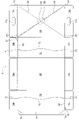
第一実施形態の包装箱1は、図1に示すように、角筒状の壁部10と、壁部10の下縁部に連設された底板30と、壁部10の上縁部に連設された頂板20と、を備えているラップアラウンド方式の段ボール箱である。
壁部10は、平面視で四角形の角筒状に形成されており、前後一対の前端壁11および後端壁12と、左右一対の左側壁13および右側壁14と、を備えている。壁部10の下側開口部は底板30によって閉塞され、壁部10の上側開口部は頂板20によって閉塞されている。
第一実施形態の包装箱1に収容する内容物は限定されるものではないが、例えば、複数のペットボトルを内容物として収容することができる。
[First embodiment]
The
The
Although the contents accommodated in the
第一実施形態の包装箱1は、図2に示すように、一枚の段ボール製のシートを切り抜いたブランクシートSを各罫線において山折りまたは谷折りすることで形成される。図2に示すブランクシートSは外面側が見えるように配置されている。
ブランクシートSの各罫線(折線)は、ブランクシートSの表面を押し込んで形成された線状の溝(押罫)である。なお、罫線上に断続的なスリットを形成してもよい。このようにすると、罫線においてブランクシートSを折り曲げ易くなる。
As shown in FIG. 2, the
Each ruled line (folded line) of the blank sheet S is a linear groove (press ruled line) formed by pressing the surface of the blank sheet S. As shown in FIG. Note that intermittent slits may be formed on the ruled lines. By doing so, it becomes easier to fold the blank sheet S at the ruled line.
底板30は、図1に示すように、四角形の平板である。底板30の外周縁部に壁部10の下縁部が連設されている。
底板30の左縁部には、罫線を介して左側壁13が連設され、底板30の右縁部には、罫線を介して右側壁14が連設されている。
左側壁13および右側壁14は、同じ四角形の壁体であり、底板30に対して垂直に形成されている。
The
A
The
右側壁14の上縁部には、罫線を介して頂板20が連設されている。頂板20は、底板30と同じ四角形の平板であり、右側壁14に対して垂直に形成されている。
左側壁13の上縁部には、罫線を介して接合片15が連設されている。接合片15は、左側壁13の上縁部に沿って形成された帯状の部位である。
ブランクシートS(図2参照)を各罫線で折り曲げつつ、左側壁13の上縁部に連設された接合片15を頂板20の内面に接合することで、左側壁13、底板30、右側壁14および頂板20が角筒状に形成されている。
A
A connecting
While bending the blank sheet S (see FIG. 2) along the respective ruled lines, the joining
前端壁11は、頂板20および底板30の前縁部にそれぞれ連設された上下一対の外フラップ16a,16aと、左側壁13および右側壁14の前縁部にそれぞれ連設された左右一対の内フラップ16b,16bと、を備えている。
左右の内フラップ16b,16bの外面に上下の外フラップ16a,16aが重ねられて接着されている。
上下の外フラップ16a,16aは、上下方向に間隔を空けて配置され、左右の内フラップ16b,16bは、左右方向に間隔を空けて配置されている。これにより、前端壁11の中央部には、四角形の開口部が形成されている。
また、上側の外フラップ16aには、手掛け穴16cが形成されている。手掛け穴16cは、包装箱1を持ち上げるときに指を掛ける部位である。
ブランクシートS(図2参照)の状態では、手掛け穴16cは塞がれており、包装箱1を使用する際に手掛け穴16cを形成できるように、手掛け穴16cの周縁部は、罫線、カット線、ハーフカット線などの任意の組合せで構成されている。
The
The upper and lower
The upper and lower
Further, a
In the state of the blank sheet S (see FIG. 2), the
後端壁12は、前端壁11と同じ構成であり、上下一対の外フラップ16a,16aと、左右一対の内フラップ16b,16bと、によって構成されている。また、後端壁12にも開口部および手掛け穴16cが形成されている。
The
第一実施形態の包装箱1では、頂板20の中央部に開封開始部50が形成されている。開封開始部50は、頂板20の左前の角部21と右後の角部24とを結ぶ一方の対角線の中央部に形成された開口部である。開封開始部50は、一方の対角線に沿って略長方形に形成されている。
In the
ブランクシートS(図2参照)の状態では、開封開始部50は蓋板51によって塞がれている。蓋板51の前後の縁部には、ライナおよびフルート(中芯)を切り込んだ断続的なカット線が形成され、蓋板51の左右の縁部には罫線が形成されている。また、蓋板51内の一方の対角線上にハーフカット線が形成されている。
包装箱1を組み立てたときには、開封開始部50は蓋板51によって塞がれており、包装箱1の開封時に、開封開始部50内の蓋板51を内側に押し込んで、開封開始部50を開口させる。
In the state of the blank sheet S (see FIG. 2), the
When the
なお、第一実施形態では、開封開始部50内の蓋板51を内側に押し込んだときに、蓋板51が内容物に当たらないように、開封開始部50の位置が設定されている。例えば、内容物が複数のペットボトルである場合には、並べられたペットボトルのキャップ同士の間に開封開始部50を配置している。
In the first embodiment, the position of the
頂板20には、開封開始部50から頂板20の二組の対角のうちの一方の対角(左前の角部21および右後の角部24)に向けて延びている頂部切断誘導線60が形成されている。頂部切断誘導線60は、Y字形状の切れ込みを断続的に形成したミシン目状の線である。
頂部切断誘導線60は、頂板20の二組の対角線のうちの一方の対角線(頂板20の左前の角部21と右後の角部24とを結ぶ対角線)に形成されている。
The
The top
前端壁11の左右の内フラップ16b,16bには、第一横切断誘導線71が形成されている(図2参照)。第一横切断誘導線71は、直線状の切れ込みを断続的に形成したミシン目状の線である。
第一横切断誘導線71は、左右方向に延びており、内フラップ16bを上下に区画している。第一横切断誘導線71は、下側の外フラップ16aの上縁部と重なる位置に形成されている。
A first transverse cutting
The first
後端壁12の左右の内フラップ16b,16bにも前端壁11と同様に、第一横切断誘導線71が形成されている。
Similarly to the
左側壁13には、第二横切断誘導線72が形成されている。第二横切断誘導線72は、直線状の切れ込みを断続的に形成したミシン目状の線である。
第二横切断誘導線72は、前後方向に延びており、左側壁13を上下に区画している。第一実施形態の第二横切断誘導線72は、上下に繰り返して湾曲した波線となっている。
第二横切断誘導線72の前後の両端部は、前後の第一横切断誘導線71,71(図2参照)にそれぞれ連続している。
A second transverse cutting
The second transverse cutting
The front and rear end portions of the second transverse-cutting
また、右側壁14にも左側壁13と同様に、第二横切断誘導線72が形成されている。
そして、前後の第一横切断誘導線71,71および左右の第二横切断誘導線72,72によって壁部10全体が上下に区画されている。
Further, the
The
前端壁11の左側の内フラップ16bの上縁部には、窪み部81が形成されている(図2参照)。窪み部81は、左側の内フラップ16bの上縁部において、左端部(左側壁13側の端部)を下方に向けて窪ませた部位である。
窪み部81によって、左側の内フラップ16bの上端部が、左側壁13の前縁部から離れている。つまり、左側の内フラップ16bと左側壁13との間の罫線の上端部が切り開かれた状態となっている。
A
A
前端壁11の左側の内フラップ16bと、左側壁13との間の罫線上には、縦切断誘導線82が形成されている。縦切断誘導線82は、屈曲した切れ込みを断続的に形成したミシン目状の線である。
縦切断誘導線82の上端部は、窪み部81の下端部に連続している。これにより、縦切断誘導線82の上端部は、窪み部81を介して頂部切断誘導線60の前端部に連続している。
縦切断誘導線82の下端部は、第一横切断誘導線71と第二横切断誘導線72との接点に連続している。
A vertical
The upper end of the vertical
A lower end portion of the vertical-cutting
後端壁12の右側の内フラップ16bにも、前端壁11の左側の内フラップ16bと同様に、窪み部81が形成されている。また、後端壁12の右側の内フラップ16bと右側壁14との間の罫線にも、前端壁11と左側壁13との間の縦切断誘導線82と同様に、縦切断誘導線82が形成されている。
The right
頂板20には、開封開始部50から頂板20の二組の対角のうちの他方の対角(右前の角部22および左後の角部23)に向けて延びている頂部罫線90が形成されている。
頂部罫線90は、頂板20の内面(下面)を押し込んで形成された線状の溝(押罫)である。第一実施形態の各図では、頂部罫線90の位置を分かり易く示すために、頂板20の外面(上面)に実線で示している。
頂部罫線90は、頂板20の二組の対角線のうちの他方の対角線(頂板20の右前の角部22と左後の角部23とを結ぶ対角線)に形成されている。
The
The
The top ruled
第一実施形態の接合片15には、頂部切断誘導線60に重なる罫線15aと、頂部罫線90に重なる罫線15bとが形成されている。
The
次に、第一実施形態の包装箱1を開封する手順について説明する。
まず、作業者は、図1に示す頂板20の開封開始部50内の蓋板51を外側から内側に向けて押し込み、開封開始部50を開口させる。
Next, a procedure for opening the
First, an operator pushes the
続いて、作業者は、図3に示すように、開封開始部50の開口縁部に指先を掛けて、頂板20において左前の角部21と右後の角部24とを結ぶ一方の対角線よりも右半分の部位および左半分の部位をそれぞれ上方に引き上げる。
これにより、頂部切断誘導線60が開封開始部50から左前の角部21および右後の角部24に向けて切り開かれる。
このとき、頂板20は頂部罫線90を折線として上方に向けて折れ曲がるため、頂板20を上方に向けて大きく引き出すことができる。
Subsequently, as shown in FIG. 3, the operator puts his or her fingertip on the edge of the opening of the
As a result, the top
At this time, the
なお、接合片15の前後の角部は、罫線15aおよび罫線15b(図2参照)において折れ曲がるため、頂部切断誘導線60を切り開いたときに、接合片15の角部が頂板20に引っ掛かったり、頂部罫線90の屈曲を妨げたりすることがない。
Since the front and rear corners of the joining
頂部切断誘導線60が左前の角部21まで切り開かれると、前端壁11の左側の内フラップ16bの窪み部81に達する。これにより、前端壁11と左側壁13との間の罫線の上端部が切り開かれた状態となる。
When the top
さらに、頂板20の右半分を引き上げると、図4に示すように、窪み部81から前側の縦切断誘導線82が下方に向けて切り開かれる。
縦切断誘導線82が下端部まで切り開かれると、前端壁11の左側の内フラップ16bの第一横切断誘導線71が切り開かれ、続いて、前端壁11の右側の内フラップ16bの第一横切断誘導線71が切り開かれる。その後、右側壁14の第二横切断誘導線72が前端部から後方に向けて切り開かれる。
Furthermore, when the right half of the
When the longitudinal
また、頂部切断誘導線60が右後の角部24まで切り開かれると、後端壁12の右側の内フラップ16bの窪み部81に達する。これにより、後端壁12と右側壁14との間の罫線の上端部が切り開かれた状態となる。
さらに、窪み部81から後側の縦切断誘導線82が下方に向けて切り開かれた後に、右側壁14の第二横切断誘導線72が後端部から前方に向けて切り開かれる。
Further, when the top
Furthermore, after the vertical
右側壁14の第二横切断誘導線72全体が切り開かれると、壁部10の前端壁11および右側壁14が上下に分割され、頂板20の右半分、前端壁11の上部および右側壁14の上部が包装箱1から切り離される。
When the entire second transverse cutting
一方、作業者が頂板20の左半分を引き上げると、後端壁12の右側の内フラップ16bの第一横切断誘導線71が切り開かれ、続いて、後端壁12の左側の内フラップ16bの第一横切断誘導線71が切り開かれる。その後、左側壁13の第二横切断誘導線72が後端部から前方に向けて切り開かれる。また、左側壁13の第二横切断誘導線72が前端部から後方に向けて切り開かれる。
On the other hand, when the operator pulls up the left half of the
左側壁13の第二横切断誘導線72全体が切り開かれると、壁部10の後端壁12および左側壁13が上下に分割され、頂板20の左半分、後端壁12の上部および左側壁13の上部が包装箱1から切り離される。
このようにして、包装箱1を開封すると、包装箱1の下部はトレイとなるため、内容物をトレイに収容した状態で陳列できる。
When the entire second transverse cutting
In this way, when the
以上のような包装箱1では、図3に示すように、開封開始部50に指先を掛けて、頂板20を引き上げると、頂板20が頂部罫線90を折線として上方に向けて折れ曲がる。これにより、包装箱1では、頂板20を小さな力で上方に向けて大きく引き出して、頂部切断誘導線60を切り開くことができるため、容易に開封してトレイを形成できる。
In the
第一実施形態の包装箱1では、頂部切断誘導線60を端部まで切り開くと、前端壁11と左側壁13との間の窪み部81および後端壁12と右側壁14との間の窪み部81に達する。窪み部81には縦切断誘導線82が連続しているため、頂部切断誘導線60に続いて縦切断誘導線82をスムーズに切り開くことができる。
In the
第一実施形態の包装箱1では、図1に示すように、縦切断誘導線82が端壁11,12と側壁13,14との間の罫線上に形成されている。このようにすると、壁部10に縦切断誘導線82を形成しても、壁部10の強度低下を抑えることができる。
In the
以上、本発明の第一実施形態について説明したが、本発明は前記実施形態に限定されることなく、その趣旨を逸脱しない範囲で適宜に変更が可能である。
第一実施形態の包装箱1は、図1に示すように、頂板20および底板30が四角形に形成されているが、頂板20および底板30の形状は限定されるものではなく、五角形や六角形など四角形よりも角部が多い形状でもよい。
この場合の頂板20には、開封開始部50から頂板20の複数の対角のうちの一の対角に向けて頂部切断誘導線60を延ばすとともに、開封開始部50から頂板20の複数の対角のうちの他の対角に向けて頂部罫線90を延ばす。
Although the first embodiment of the present invention has been described above, the present invention is not limited to the above-described embodiment and can be appropriately modified without departing from the scope of the invention.
As shown in FIG. 1, the
In this case, the
第一実施形態の包装箱1では、頂板20の中央部に開封開始部50を形成しているが、開封開始部50の位置は限定されるものではなく、内容物の収容状態に応じて、開封開始部50の位置が設定される。また、第一実施形態の開封開始部50は開口部であるが、開封開始部50の形状は限定されるものではなく、例えば、スリットによって開封開始部を構成してもよい。
In the
第一実施形態の包装箱1では、頂板20の一方の対角線上に頂部切断誘導線60が形成されるとともに、他方の対角線上に頂部罫線90が形成されているが、頂部切断誘導線および頂部罫線を対角線上に形成しなくてもよい。また、頂部切断誘導線60を屈曲や湾曲させてもよい。
In the
第一実施形態の包装箱1では、端壁11,12と側壁13,14との間の罫線上に縦切断誘導線82が形成されているが、その位置は限定されるものではなく、端壁11,12または側壁13,14に形成してもよい。
In the
第一実施形態の包装箱1では、上下の外フラップ16a,16aが上下方向に間隔を空けて配置されているが、上下の外フラップ16a,16aを突き合わせてもよい。
In the
第一実施形態の包装箱1は、ラップアラウンド方式の段ボール箱であるが、本発明の包装箱の形式は限定されるものではない。例えば、A式のダンボール箱に本発明を適用してもよい。
第一実施形態の包装箱1は段ボール製であるが、各種公知の板紙によって包装箱を形成してもよい。
The
Although the
[第二実施形態]
次に、第二実施形態の包装箱1Aについて説明する。
第二実施形態の包装箱1Aは、図5に示すように、前記した第一実施形態の包装箱1(図1参照)と略同様の構成であり、開封開始部150、頂部切断誘導線160、頂部罫線190の構成が異なっている。
[Second embodiment]
Next, 1 A of packaging boxes of 2nd embodiment are demonstrated.
As shown in FIG. 5, the
第二実施形態の開封開始部150は、頂板20の中央部に形成され、前後方向に延びている直線状のスリット151と、スリット151の前端部および後端部にそれぞれ接続された前後の開口部152,152と、から構成されている。ブランクシートの状態において前後の開口部152,152は蓋板によって塞がれている。
The
第二実施形態の頂部切断誘導線160は、前側の開口部152から左前の角部21に向けて延びているとともに、後側の開口部152から右後の角部24に向けて延びている。このように、頂部切断誘導線160は、開封開始部150から頂板20の二組の対角のうちの一方の対角に向けて延びている。
The top
第二実施形態の頂部罫線190は、前側の開口部152から右前の角部22に向けて延びているとともに、後側の開口部152から左後の角部23に向けて延びている。このように、頂部罫線190は、開封開始部150から頂板20の二組の対角のうちの他方の対角に向けて延びている。
The top ruled
以上のような第二実施形態の包装箱1Aでは、開封開始部150の両開口部152,152に指先を掛けて、頂板20を引き上げると、頂板20が頂部罫線190を折線として上方に向けて折れ曲がる。これにより、包装箱1Aでは、頂板20を小さな力で上方に向けて大きく引き出して、頂部切断誘導線160を切り開くことができる。
In the
また、第二実施形態の包装箱1Aでは、第一実施形態の開封開始部50(図1参照)に比べて、開封開始部150の蓋板を小さくできるため、開封開始部150の蓋板を押し込んだときに、蓋板が内容物に干渉しないように、内容物の配置に応じて開封開始部150を配置し易くなる。
In addition, in the
1 包装箱(第一実施形態)
1A 包装箱(第二実施形態)
10 壁部
11 前端壁
12 後端壁
13 左側壁
14 右側壁
15 接合片
16a 外フラップ
16b 内フラップ
16c 手掛け穴
20 頂板
30 底板
50 開封開始部(第一実施形態)
51 蓋板
60 頂部切断誘導線(第一実施形態)
71 第一横切断誘導線
72 第二横切断誘導線
81 窪み部
82 縦切断誘導線
90 頂部罫線(第一実施形態)
150 開封開始部(第二実施形態)
151 スリット
152 開口部
160 頂部切断誘導線(第二実施形態)
190 頂部罫線(第二実施形態)
S ブランクシート
1 packaging box (first embodiment)
1A packaging box (second embodiment)
REFERENCE SIGNS
51
71 first
150 Opening start part (second embodiment)
151
190 top ruled line (second embodiment)
S blank sheet
Claims (1)
前記壁部の下縁部に連設された底板と、
前記壁部の上縁部に連設された頂板と、を備え、
前記頂板の中央部に開封開始部が形成され、
前記頂板には、
前記開封開始部から一の対角に向けて延びている頂部切断誘導線と、
前記開封開始部から他の対角に向けて延びている頂部罫線と、が形成され、
前記壁部には、
前記壁部を上下に区画している横切断誘導線と、
前記頂部切断誘導線の端部から前記横切断誘導線に連続している縦切断誘導線と、が形成され、
前記縦切断誘導線は、前記端壁と前記側壁との間の罫線上に形成されており、
前記端壁は、
前記頂板および前記底板にそれぞれ連設された上下一対の外フラップと、
左右の前記側壁にそれぞれ連設された左右一対の内フラップと、を備え、
左右の前記内フラップの外面に上下の前記外フラップが重ねられており、
前記内フラップの上縁部の端部には、下方に向けて窪ませた窪み部が形成され、
前記頂部切断誘導線と前記縦切断誘導線とは、前記窪み部を介して連続していることを特徴とする包装箱。 a cylindrical wall portion having a pair of front and rear end walls and a pair of left and right side walls;
a bottom plate connected to the lower edge of the wall;
and a top plate connected to the upper edge of the wall,
An opening start portion is formed in the central portion of the top plate,
The top plate includes:
a top cutting guide line extending from the opening start portion toward one diagonal;
and a top ruled line extending from the opening start portion toward another diagonal corner,
In the wall part,
a transverse cutting guide line that divides the wall into upper and lower parts;
a longitudinal cutting guide line continuing from the end of the top cutting guide line to the transverse cutting guide line ;
The vertical cutting guide line is formed on a ruled line between the end wall and the side wall,
The end wall is
a pair of upper and lower outer flaps respectively connected to the top plate and the bottom plate;
a pair of left and right inner flaps connected to the left and right side walls, respectively;
The upper and lower outer flaps are superimposed on the outer surfaces of the left and right inner flaps,
A concave portion that is concaved downward is formed at the end of the upper edge of the inner flap,
The packaging box , wherein the top cut guide line and the vertical cut guide line are continuous through the recess .
Priority Applications (1)
| Application Number | Priority Date | Filing Date | Title |
|---|---|---|---|
| JP2019007830A JP7192517B2 (en) | 2019-01-21 | 2019-01-21 | packaging box |
Applications Claiming Priority (1)
| Application Number | Priority Date | Filing Date | Title |
|---|---|---|---|
| JP2019007830A JP7192517B2 (en) | 2019-01-21 | 2019-01-21 | packaging box |
Publications (2)
| Publication Number | Publication Date |
|---|---|
| JP2020117242A JP2020117242A (en) | 2020-08-06 |
| JP7192517B2 true JP7192517B2 (en) | 2022-12-20 |
Family
ID=71891701
Family Applications (1)
| Application Number | Title | Priority Date | Filing Date |
|---|---|---|---|
| JP2019007830A Active JP7192517B2 (en) | 2019-01-21 | 2019-01-21 | packaging box |
Country Status (1)
| Country | Link |
|---|---|
| JP (1) | JP7192517B2 (en) |
Citations (3)
| Publication number | Priority date | Publication date | Assignee | Title |
|---|---|---|---|---|
| JP2015089833A (en) | 2013-11-07 | 2015-05-11 | サッポロビール株式会社 | Sheet for packaging carton and package body |
| JP2015110446A (en) | 2013-11-08 | 2015-06-18 | 協和ダンボール株式会社 | Box |
| JP2018177373A (en) | 2017-04-05 | 2018-11-15 | サントリーホールディングス株式会社 | Corrugated carton |
Family Cites Families (2)
| Publication number | Priority date | Publication date | Assignee | Title |
|---|---|---|---|---|
| JPS59193126U (en) * | 1983-06-08 | 1984-12-21 | レンゴ−株式会社 | packaging box |
| US6024279A (en) * | 1997-10-30 | 2000-02-15 | Georgia-Pacific Corp. | Bulk container formed from blank having T-shaped slots separating closure flaps |
-
2019
- 2019-01-21 JP JP2019007830A patent/JP7192517B2/en active Active
Patent Citations (3)
| Publication number | Priority date | Publication date | Assignee | Title |
|---|---|---|---|---|
| JP2015089833A (en) | 2013-11-07 | 2015-05-11 | サッポロビール株式会社 | Sheet for packaging carton and package body |
| JP2015110446A (en) | 2013-11-08 | 2015-06-18 | 協和ダンボール株式会社 | Box |
| JP2018177373A (en) | 2017-04-05 | 2018-11-15 | サントリーホールディングス株式会社 | Corrugated carton |
Also Published As
| Publication number | Publication date |
|---|---|
| JP2020117242A (en) | 2020-08-06 |
Similar Documents
| Publication | Publication Date | Title |
|---|---|---|
| JP5960547B2 (en) | Ruled line structure for breaking paper containers and paper products | |
| JP6503883B2 (en) | Packaging box | |
| JPH07257546A (en) | Base stock for thick paper box and thick paper box | |
| JP7192517B2 (en) | packaging box | |
| JP7044302B2 (en) | Manufacturing method for packaging boxes and blanks | |
| JP6523648B2 (en) | Packaging box | |
| JP7267838B2 (en) | packaging box | |
| JP6648744B2 (en) | Packaging box | |
| JP7196742B2 (en) | packaging box | |
| JP7415906B2 (en) | Packaging boxes and how to assemble packaging boxes | |
| JP2019214402A (en) | Packing box | |
| JP7475878B2 (en) | Packaging box | |
| JP6969697B1 (en) | Packaging box | |
| JP7052909B1 (en) | Packaging box | |
| JP7218248B2 (en) | packaging box | |
| JP7435398B2 (en) | packaging box | |
| JP7310528B2 (en) | packaging box | |
| JP7473309B2 (en) | Packaging box | |
| JP7175790B2 (en) | packaging box | |
| JP7380200B2 (en) | packaging box | |
| JP5235167B2 (en) | Ruled line structure of paper product and paper product using the ruled line structure | |
| JP7192897B2 (en) | packaging box | |
| JP7247653B2 (en) | packaging box | |
| JP7221201B2 (en) | packaging box | |
| JP7224886B2 (en) | Cutting line and packaging box with this |
Legal Events
| Date | Code | Title | Description |
|---|---|---|---|
| A621 | Written request for application examination |
Free format text: JAPANESE INTERMEDIATE CODE: A621 Effective date: 20210714 |
|
| A977 | Report on retrieval |
Free format text: JAPANESE INTERMEDIATE CODE: A971007 Effective date: 20220617 |
|
| A131 | Notification of reasons for refusal |
Free format text: JAPANESE INTERMEDIATE CODE: A131 Effective date: 20220802 |
|
| A521 | Request for written amendment filed |
Free format text: JAPANESE INTERMEDIATE CODE: A523 Effective date: 20220831 |
|
| TRDD | Decision of grant or rejection written | ||
| A01 | Written decision to grant a patent or to grant a registration (utility model) |
Free format text: JAPANESE INTERMEDIATE CODE: A01 Effective date: 20221108 |
|
| A61 | First payment of annual fees (during grant procedure) |
Free format text: JAPANESE INTERMEDIATE CODE: A61 Effective date: 20221121 |
|
| R150 | Certificate of patent or registration of utility model |
Ref document number: 7192517 Country of ref document: JP Free format text: JAPANESE INTERMEDIATE CODE: R150 |