JP7187182B2 - Data generator, method and program - Google Patents
Data generator, method and program Download PDFInfo
- Publication number
- JP7187182B2 JP7187182B2 JP2018111163A JP2018111163A JP7187182B2 JP 7187182 B2 JP7187182 B2 JP 7187182B2 JP 2018111163 A JP2018111163 A JP 2018111163A JP 2018111163 A JP2018111163 A JP 2018111163A JP 7187182 B2 JP7187182 B2 JP 7187182B2
- Authority
- JP
- Japan
- Prior art keywords
- data
- dimensional shape
- information
- image
- color
- Prior art date
- Legal status (The legal status is an assumption and is not a legal conclusion. Google has not performed a legal analysis and makes no representation as to the accuracy of the status listed.)
- Active
Links
Images


Classifications
-
- G—PHYSICS
- G06—COMPUTING; CALCULATING OR COUNTING
- G06T—IMAGE DATA PROCESSING OR GENERATION, IN GENERAL
- G06T17/00—Three dimensional [3D] modelling, e.g. data description of 3D objects
-
- H—ELECTRICITY
- H04—ELECTRIC COMMUNICATION TECHNIQUE
- H04N—PICTORIAL COMMUNICATION, e.g. TELEVISION
- H04N13/00—Stereoscopic video systems; Multi-view video systems; Details thereof
- H04N13/10—Processing, recording or transmission of stereoscopic or multi-view image signals
- H04N13/106—Processing image signals
- H04N13/15—Processing image signals for colour aspects of image signals
-
- G—PHYSICS
- G06—COMPUTING; CALCULATING OR COUNTING
- G06T—IMAGE DATA PROCESSING OR GENERATION, IN GENERAL
- G06T15/00—3D [Three Dimensional] image rendering
- G06T15/10—Geometric effects
-
- G—PHYSICS
- G06—COMPUTING; CALCULATING OR COUNTING
- G06T—IMAGE DATA PROCESSING OR GENERATION, IN GENERAL
- G06T15/00—3D [Three Dimensional] image rendering
- G06T15/04—Texture mapping
-
- G—PHYSICS
- G06—COMPUTING; CALCULATING OR COUNTING
- G06T—IMAGE DATA PROCESSING OR GENERATION, IN GENERAL
- G06T15/00—3D [Three Dimensional] image rendering
- G06T15/10—Geometric effects
- G06T15/20—Perspective computation
-
- G—PHYSICS
- G06—COMPUTING; CALCULATING OR COUNTING
- G06T—IMAGE DATA PROCESSING OR GENERATION, IN GENERAL
- G06T19/00—Manipulating 3D models or images for computer graphics
-
- G—PHYSICS
- G06—COMPUTING; CALCULATING OR COUNTING
- G06T—IMAGE DATA PROCESSING OR GENERATION, IN GENERAL
- G06T19/00—Manipulating 3D models or images for computer graphics
- G06T19/20—Editing of 3D images, e.g. changing shapes or colours, aligning objects or positioning parts
-
- H—ELECTRICITY
- H04—ELECTRIC COMMUNICATION TECHNIQUE
- H04N—PICTORIAL COMMUNICATION, e.g. TELEVISION
- H04N13/00—Stereoscopic video systems; Multi-view video systems; Details thereof
- H04N13/10—Processing, recording or transmission of stereoscopic or multi-view image signals
- H04N13/106—Processing image signals
- H04N13/111—Transformation of image signals corresponding to virtual viewpoints, e.g. spatial image interpolation
- H04N13/117—Transformation of image signals corresponding to virtual viewpoints, e.g. spatial image interpolation the virtual viewpoint locations being selected by the viewers or determined by viewer tracking
-
- H—ELECTRICITY
- H04—ELECTRIC COMMUNICATION TECHNIQUE
- H04N—PICTORIAL COMMUNICATION, e.g. TELEVISION
- H04N13/00—Stereoscopic video systems; Multi-view video systems; Details thereof
- H04N13/10—Processing, recording or transmission of stereoscopic or multi-view image signals
- H04N13/189—Recording image signals; Reproducing recorded image signals
-
- H—ELECTRICITY
- H04—ELECTRIC COMMUNICATION TECHNIQUE
- H04N—PICTORIAL COMMUNICATION, e.g. TELEVISION
- H04N13/00—Stereoscopic video systems; Multi-view video systems; Details thereof
- H04N13/20—Image signal generators
- H04N13/282—Image signal generators for generating image signals corresponding to three or more geometrical viewpoints, e.g. multi-view systems
-
- H—ELECTRICITY
- H04—ELECTRIC COMMUNICATION TECHNIQUE
- H04N—PICTORIAL COMMUNICATION, e.g. TELEVISION
- H04N13/00—Stereoscopic video systems; Multi-view video systems; Details thereof
- H04N13/20—Image signal generators
- H04N13/293—Generating mixed stereoscopic images; Generating mixed monoscopic and stereoscopic images, e.g. a stereoscopic image overlay window on a monoscopic image background
-
- G—PHYSICS
- G06—COMPUTING; CALCULATING OR COUNTING
- G06T—IMAGE DATA PROCESSING OR GENERATION, IN GENERAL
- G06T2207/00—Indexing scheme for image analysis or image enhancement
- G06T2207/10—Image acquisition modality
- G06T2207/10024—Color image
-
- G—PHYSICS
- G06—COMPUTING; CALCULATING OR COUNTING
- G06T—IMAGE DATA PROCESSING OR GENERATION, IN GENERAL
- G06T2219/00—Indexing scheme for manipulating 3D models or images for computer graphics
- G06T2219/20—Indexing scheme for editing of 3D models
- G06T2219/2021—Shape modification
Landscapes
- Engineering & Computer Science (AREA)
- Physics & Mathematics (AREA)
- Theoretical Computer Science (AREA)
- Multimedia (AREA)
- Signal Processing (AREA)
- Computer Graphics (AREA)
- General Physics & Mathematics (AREA)
- Geometry (AREA)
- Software Systems (AREA)
- Computer Hardware Design (AREA)
- General Engineering & Computer Science (AREA)
- Computing Systems (AREA)
- Architecture (AREA)
- Processing Or Creating Images (AREA)
- Image Processing (AREA)
- Image Generation (AREA)
Description
本発明は、複数の視点から撮像した画像に基づき、仮想視点からの画像を生成する技術に関する。 The present invention relates to a technique for generating images from virtual viewpoints based on images captured from a plurality of viewpoints.
昨今、複数のカメラを異なる位置に設置して複数視点で同期撮像を行い、当該撮像により得られた複数の画像を用いて仮想視点コンテンツを生成する技術が注目されている。この複数の画像から仮想視点コンテンツを生成する技術によれば、例えば、サッカーやバスケットボールのハイライトシーンを様々な角度から視聴することが可能になるため、ユーザにより高い臨場感を与えることができる。 2. Description of the Related Art In recent years, attention has been paid to a technique in which a plurality of cameras are installed at different positions, synchronous imaging is performed from a plurality of viewpoints, and virtual viewpoint content is generated using a plurality of images obtained by the imaging. According to this technique of generating virtual viewpoint content from a plurality of images, for example, it is possible to view the highlight scenes of soccer or basketball from various angles, so that a higher sense of presence can be given to the user.
仮想視点画像の生成及び閲覧には、複数のカメラが撮像した画像データのサーバなどへの集約、当該サーバなどにおける三次元モデルの生成やレンダリングなどの画像処理が必要となり得る。特許文献1には、実空間を分割した局所領域それぞれに応じてカメラパラメータおよび画像などを調整することによって、複数台のカメラの画像から、現実に近い実空間上の任意の視点の画像を生成する技術が開示されている。
Generation and viewing of virtual viewpoint images may require collection of image data captured by a plurality of cameras in a server or the like, and image processing such as generation or rendering of a three-dimensional model in the server or the like. In
しかしながら、上述の特許文献1の技術では、複数台のカメラの画像を用いて仮想視点画像を生成するため、仮想視点画像の生成に要する画像のデータ量が非常に多くなってしまうという課題がある。
However, the technique of
そこで、本発明は、データ量を削減しながらも、仮想視点画像を得ることができるようにすることを目的とする。 SUMMARY OF THE INVENTION Accordingly, it is an object of the present invention to obtain a virtual viewpoint image while reducing the amount of data.
上記課題を解決するため、本発明の一態様に係るデータ生成装置は、複数の撮像装置で撮像されることにより取得される複数の画像に基づき、オブジェクトの形状を示す三次元形状データを生成する第1の生成手段と、前記複数の画像に基づいて、前記第1の生成手段により生成された前記三次元形状データの要素の色を示す色情報を生成する第2の生成手段と、前記複数の画像に基づいて、前記第1の生成手段により生成された前記三次元形状データの要素の色を仮想視点に応じて補正するための色補正情報を生成する第3の生成手段と、前記第1の生成手段により生成された前記三次元形状データと前記第2の生成手段により生成された前記色情報と、前記第3の生成手段により生成された色補正情報を関連付けて記憶手段に記憶させる記憶制御手段と、を有する、ことを特徴とする。 In order to solve the above problems, a data generation device according to one aspect of the present invention generates three-dimensional shape data representing the shape of an object based on a plurality of images captured by a plurality of imaging devices. a first generating means for generating, based on the plurality of images, second generating means for generating color information indicating colors of elements of the three-dimensional shape data generated by the first generating means; a third generating means for generating, based on the plurality of images, color correction information for correcting the colors of the elements of the three-dimensional shape data generated by the first generating means according to a virtual viewpoint; a storage means for associating the three-dimensional shape data generated by the first generating means, the color information generated by the second generating means , and the color correction information generated by the third generating means; and storage control means for storing the
本発明によれば、データ量を削減しながらも、仮想視点画像を得ることができるようになる。 According to the present invention, it is possible to obtain a virtual viewpoint image while reducing the amount of data.
以下、本発明の実施形態について図面を参照して説明する。ただし、この実施形態に記載されている構成要素はあくまで例示であり、本発明の範囲をそれらに限定する趣旨のものではない。また、実施形態で説明されている構成要素の組み合わせのすべてが、課題を解決するための手段に必須のものとは限らず、特許請求の範囲に記載された本発明の要旨の範囲内において、種々の変形及び変更が可能である。 BEST MODE FOR CARRYING OUT THE INVENTION Hereinafter, embodiments of the present invention will be described with reference to the drawings. However, the constituent elements described in this embodiment are merely examples, and are not intended to limit the scope of the present invention. In addition, not all combinations of the components described in the embodiments are essential to the means for solving the problems, and within the scope of the gist of the invention described in the claims, Various modifications and alterations are possible.
本明細書において符号の末尾のアルファベットは、同種の構成において個々の構成を識別するために用いている。末尾のアルファベットを省略して記載する場合、個々の構成を特に区別せずに記載しているものとする。 In this specification, alphabetical letters at the end of reference numerals are used to identify individual configurations in similar configurations. When description is made by omitting the alphabet at the end, it is assumed that each configuration is described without particular distinction.
[実施形態1]
<システム構成>
図1は、本実施形態に係る画像処理システムの構成例を示す図である。本実施形態の画像処理システム100は、例えば競技場(スタジアム)やコンサートホールなどの施設に、複数のカメラ及びマイクを設置し、撮像及び集音を行う形態のものである。画像処理システム100は、センサシステム110a-110z、画像コンピューティングサーバ200、コントローラ300、スイッチングハブ180、及びエンドユーザ端末190を有する。
[Embodiment 1]
<System configuration>
FIG. 1 is a diagram showing a configuration example of an image processing system according to this embodiment. The
コントローラ300は、制御ステーション310と仮想カメラ操作UI(User Interface)330を有する。制御ステーション310は、画像処理システム100を構成するそれぞれのブロック(サーバまたは装置など)に対してネットワーク310a,310b,310c,180a,180b、及びデイジーチェーン170a-170yを通じた制御が可能である。例えば、制御ステーション310は、各ブロックの動作状態の管理及びパラメータ設定制御などを行う。上記のネットワークは、Ethernet(登録商標)であるIEEE標準準拠のGbE(ギガビットイーサーネット)や10GbEでもよいし、インターコネクトInfiniband、産業用イーサーネット等を組み合わせて構成されてもよい。また、これらに限定されず、他の種別のネットワークであってもよい。
The
センサシステム110a-110zは、26セットの画像及び音声をセンサシステム110zから画像コンピューティングサーバ200へ送信する。本実施形態の画像処理システム100では、センサシステム110a-110zが、デイジーチェーンにより接続される。このため、各センサシステムで得られた画像及び音声は、チェーン接続されている下流側のセンサシステムに順次伝送される。そして、最下流のセンサシステム110zから、26セット分の画像及び音声が、ネットワーク180b及びスイッチングハブ180を介して画像コンピューティングサーバ200へ伝送される。デイジーチェーン接続の構成を採用することで、接続ケーブル数の削減や配線作業負担の軽減ができる。なお、各センサシステム110がスイッチングハブ180に接続されて、スイッチングハブ180を経由してセンサシステム110間のデータ送受信を行うスター型のネットワーク構成としてもよい。図1においては、センサシステムの台数として26セットを例に挙げて説明しているが、あくまでも一例であり、台数をこれに限定するものではない。
Sensor systems 110 a - 110 z transmit 26 sets of images and sounds from
本実施形態では、特に断りがない限り、画像という文言が、動画と静止画の概念を含むものとして説明する。すなわち、本実施形態の画像処理システム100は、静止画及び動画の何れについても処理可能である。また、本実施形態では、画像処理システム100により提供される仮想視点コンテンツには、仮想視点画像と仮想聴取点音響が含まれる例を中心に説明するが、これに限定されない。例えば、仮想視点コンテンツに音声が含まれていなくても良い。また例えば、仮想視点コンテンツに含まれる音声が、仮想視点の位置に最も近いマイクにより集音された音声であっても良いし、複数のマイクで集音された音声から作成されても良い。また、本実施形態では、説明の簡略化のため、部分的に音声についての記載を省略しているが、基本的に画像と音声は共に処理されるものとする。
In the present embodiment, unless otherwise specified, the term "image" includes the concept of moving images and still images. That is, the
センサシステム110は、マイク111、カメラ112、雲台113、外部センサ114、及びカメラアダプタ120を有する。センサシステム110は、それぞれ1台ずつのカメラ112を有する。このように画像処理システム100は、オブジェクトを複数の方向から撮像するための複数のカメラ112を有する。なお、カメラ112とカメラアダプタ120が一体となって構成されていてもよい。さらに、カメラアダプタ120の機能の少なくとも一部をフロントエンドサーバ230が有していてもよい。外部センサ114として、例えばジャイロセンサが利用される場合は、振動を表す情報を取得することができる。
The
ここで、カメラアダプタ120の動作について説明する。カメラアダプタ120は、カメラ112が撮像した撮像画像を前景画像と背景画像に分離する機能を有する。例えば、カメラアダプタ120は、カメラ112が撮像した撮像画像(以下、画像と記載することもある。)から、選手などの動作する物体(動体)を抽出した前景画像と、芝生などの静止又は静止に近い状態が継続する物体の背景画像とに分離する。ここでは、選手などの人物をオブジェクト(前景)とする。なお、オブジェクト(前景)は、ボールであってもよい。そして、カメラアダプタ120は、分離された前景画像と背景画像とを、チェーン接続されている下流側の別のカメラアダプタ120に出力する。なお、前景画像と背景画像の分離方法は背景差分法に限定されるものではなく、公知の方法を適用可能である。なお、静止物体は、静止または、ほとんど静止している状態が継続している物体を指す。
Here, the operation of
カメラアダプタ120a-120zのそれぞれで生成された、オブジェクトを含む前景画像および背景画像が下流側のカメラアダプタに順次伝送され、最下流のカメラアダプタ120zから画像コンピューティングサーバ200に出力される。これにより、画像コンピューティングサーバ200には、各カメラ112の撮像画像から生成された前景画像と背景画像とが集約される。
The foreground and background images containing the object generated by each of the camera adapters 120a-120z are sequentially transmitted to the downstream camera adapters and output to the
次に、画像コンピューティングサーバ200の構成及び動作について説明する。本実施形態の画像コンピューティングサーバ200は、センサシステム110zから取得したデータの処理を行う。画像コンピューティングサーバ200は、フロントエンドサーバ230、データベース250(以下、DBと記載することもある。)、バックエンドサーバ270、及びタイムサーバ290を有する。
Next, the configuration and operation of
タイムサーバ290は、時刻及び同期信号を配信する機能を有し、スイッチングハブ180を介してセンサシステム110a-110zに時刻及び同期信号を配信する。時刻と同期信号を受信したカメラアダプタ120a-120zは、カメラ112a-112zを、時刻と同期信号に基づき外部同期させ、画像(フレーム)の同期を行う。すなわち、タイムサーバ290は、複数のカメラ112の撮像タイミングを同期させる。これにより、画像処理システム100は、同じタイミングで撮像された複数の画像に基づいて仮想視点画像を生成できるので、撮像タイミングのずれによる仮想視点画像の品質低下を抑制できる。なお、本実施形態ではタイムサーバ290が、複数のカメラ112の時刻同期を管理するものとするが、これに限らず、時刻同期のための処理を各カメラ112又は各カメラアダプタ120が独立して行ってもよい。
The
フロントエンドサーバ230は、センサシステム110zから、各カメラ112の撮像画像から生成された前景画像および背景画像を取得する。そして、フロントエンドサーバ230は、該取得した前景画像および背景画像を用いて、オブジェクトの三次元形状を表す三次元モデル(三次元形状データ)を生成する。三次元モデルを生成する手法として、例えばVisual Hullと呼ばれる方式などが挙げられる。Visual Hull方式では、三次元モデルが存在する三次元空間を小さな立方体に区切る。そして、該立方体を各カメラの前景画像のシルエットに投影し、立方体がシルエット領域内におさまらないカメラが1台でもあった場合、立方体を削っていき、残った立方体を三次元モデルとして生成する手法である。
Front-
なお、三次元モデルを生成する手法は、Visual Hull方式に限定されるものではなく、他の手法でも良い。本実施形態では、三次元モデルは、撮像対象となる空間を一意に示す世界座標空間における三次元空間のx、y、zの位置情報を持った点群で表現されるものとする。三次元モデルは、点群で表現されるものに限定されず、他のデータ形式で表現されても良く、例えば、三角形や四角形などの単純な凸多角形(ポリゴンと呼ばれる)の面で構成されるポリゴンメッシュモデルやボクセルなどで表現されても良い。フロントエンドサーバ230は、各カメラ112の撮像画像から生成された前景画像および背景画像と、上記生成したオブジェクト三次元モデルとをDB250に格納する。また三次元モデルの形状の外郭を示す情報も併せて格納するものとする。説明を簡易にするため、外郭情報は、三次元モデルの形状の外側を囲む直方体で表す情報として説明する。なお、外郭情報は、この形状に限定されるものではなく、三次元モデルの形状の外側を囲む形状であれば良い。
Note that the method of generating the three-dimensional model is not limited to the Visual Hull method, and other methods may be used. In this embodiment, the three-dimensional model is represented by a point group having x, y, and z positional information of the three-dimensional space in the world coordinate space that uniquely indicates the space to be imaged. A three-dimensional model is not limited to being represented by a point cloud, and may be represented by other data formats. It may be represented by a polygon mesh model, voxels, or the like. The front-
すなわち、フロントエンドサーバ230は、詳細につき後述する仮想視点画像を生成するための素材データを生成し、生成した素材データをDB250に格納するデータ生成装置としての機能を有する。さらに、フロントエンドサーバ230は、詳細につき後述する、カメラで撮像した画像よりオブジェクト三次元モデルの各要素の色情報を生成し、生成した色情報をDB250に格納する機能も有する。
That is, the front-
バックエンドサーバ270は、仮想カメラ操作UI330から仮想視点の指定を受け付け、受け付けた視点に基づいて、DB250から対応する画像データ及び音声データを読み出し、レンダリング処理を行って仮想視点画像を生成する。すなわち、バックエンドサーバ270は、複数のカメラ112で撮像された撮像画像(複数視点画像)と視点情報とに基づき仮想視点画像を生成する仮想視点画像生成装置としての機能を有する。そしてバックエンドサーバ270は、生成した仮想視点画像をエンドユーザ端末190に提供する。本実施形態における仮想視点画像は、仮想的な視点からオブジェクトを撮像した場合に得られる仮想視点画像を含むコンテンツである。言い換えると、仮想視点画像は、指定された視点における位置及び方向で撮像したと仮定した場合の画像であるとも言える。仮想的な視点(仮想視点)は、ユーザにより指定されても良いし、画像解析の結果等に基づいて自動的に指定されても良い。すなわち仮想視点画像には、ユーザが任意に指定した視点に対応する任意視点画像(仮想視点画像)が含まれる。
The
なお、画像コンピューティングサーバ200の構成はこれに限定されない。例えば、フロントエンドサーバ230、DB250、及びバックエンドサーバ270のうち少なくとも2つが一体となって構成されていてもよい。また、フロントエンドサーバ230、DB250、及びバックエンドサーバ270の少なくとも何れかが複数含まれていてもよい。また、画像コンピューティングサーバ200内の任意の位置に上記の装置以外の装置が含まれていてもよい。さらに、画像コンピューティングサーバ200の機能の少なくとも一部をエンドユーザ端末190や仮想カメラ操作UI330が有していてもよい。
Note that the configuration of the
バックエンドサーバ270によって生成された仮想視点画像は、バックエンドサーバ270からエンドユーザ端末190に送信される。そのため、エンドユーザ端末190を操作するユーザは、指定した視点に応じた画像閲覧及び音声視聴を行うことができる。補足として、本実施形態では、仮想視点コンテンツに音声データ(オーディオデータ)が含まれる例を中心に説明するが、必ずしも音声データが含まれていなくてもよい。さらに、バックエンドサーバ270は、仮想視点画像をH.264やHEVCに代表される標準技術により圧縮符号化した上で、MPEG-DASHプロトコルを使ってエンドユーザ端末190に送信してもよい。また、仮想視点画像を、非圧縮でエンドユーザ端末190に送信してもよい。なお、この場合、圧縮符号化を行う前者はエンドユーザ端末190としてスマートフォンやタブレットを想定しており、後者は非圧縮画像を表示可能なディスプレイを想定している。すなわち、エンドユーザ端末190の種別に応じて画像フォーマットを切り替えることができる。その他、画像の送信プロトコルは、MPEG-DASHに限らず、例えば、HLS(HTTP Live Streaming)やそれ以外の送信方法を用いることもできる。
A virtual viewpoint image generated by the
制御ステーション310は、仮想視点画像を生成する対象のスタジアムを三次元モデルで表現したスタジアム三次元モデルを予め設定しDB250に格納している。さらに、制御ステーション310はカメラ設置時に、キャリブレーションを実施する。具体的には、撮像対象のフィールド上にマーカーを設置し、各カメラ112の撮像画像により、各カメラの世界座標における位置と向き、および焦点距離を導出する。該導出された各カメラの位置、向き、焦点距離の情報をカメラの情報(カメラパラメータ)としてDB250に格納する。DB250に格納されたスタジアム三次元モデルおよび各カメラの情報は、バックエンドサーバ270によって読み出され、該バックエンドサーバ270で仮想視点画像を生成する際に用いられる。また各カメラの情報は、フロントエンドサーバ230によって読み出され、該フロントエンドサーバ230でオブジェクト三次元モデルを生成する際に使用される。
The
なお、本実施形態における画像処理システム100は、上記で説明した物理的な構成に限定される訳ではなく、論理的に構成されていてもよい。
Note that the
次に、フロントエンドサーバ230の詳細な構成および動作について、説明する。フロントエンドサーバ230は、前景画像、背景画像およびオブジェクト三次元モデルなどの仮想視点画像を生成するための素材データを生成してDB250に格納するデータ生成装置としての機能を有しており、その詳細について、説明する。
Next, detailed configuration and operation of the front-
まず、カメラの撮像対象の空間を表現する世界座標空間と、カメラ、および該カメラの撮像対象のオブジェクト三次元モデルとの関係について、図2および図3を参照して説明する。 First, the relationship between the world coordinate space that expresses the space to be imaged by the camera and the three-dimensional model of the object to be imaged by the camera will be described with reference to FIGS. 2 and 3. FIG.
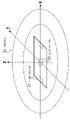
図2は、世界座標空間の一例を示す図である。世界座標空間は、例えば撮像対象を三次元空間で表現したものである。図3は、オブジェクト三次元モデルのデータ例を示す図である。ここでいう、オブジェクト三次元モデルは、オブジェクトの三次元形状を示すデータである。図2では、スタジアム21中央のサッカーフィールド22を対象に世界座標空間が設定されるとする。本実施形態では、世界座標空間を、センターサークル23の中心を原点とし、サッカーフィールド22の長辺方向(図2にて左右方向)および短辺方向のそれぞれに沿う方向をx軸およびy軸とし、上下方向(高さ方向)をz軸とした空間とする。なお、本実施形態ではサッカーフィールドを対象としたが、対象は何れでも良く、特に対象を限定するものではない。 FIG. 2 is a diagram showing an example of the world coordinate space. The world coordinate space is, for example, a representation of an object to be imaged in a three-dimensional space. FIG. 3 is a diagram showing an example of data of a three-dimensional object model. The object three-dimensional model here is data representing the three-dimensional shape of the object. In FIG. 2, it is assumed that the world coordinate space is set with the soccer field 22 in the center of the stadium 21 as the target. In this embodiment, the center of the center circle 23 is the origin of the world coordinate space, and the x-axis and y-axis are the directions along the long side direction (horizontal direction in FIG. 2) and the short side direction of the soccer field 22, respectively. , a space with the vertical direction (height direction) as the z-axis. In this embodiment, the target is a soccer field, but any target may be used, and the target is not particularly limited.
カメラが図2では不図示であるが、各カメラに関し、世界座標空間におけるカメラの座標位置と、カメラの回転角度(左右、上下)、および焦点距離と画像中心を表現するカメラパラメータが設定されるとする。 Although the cameras are not shown in FIG. 2, for each camera, the coordinate position of the camera in the world coordinate space, the rotation angle of the camera (horizontal, vertical), and the camera parameters expressing the focal length and image center are set. and
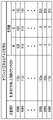
オブジェクト三次元モデルは、図3に示すように、モデルが存在する世界座標空間における、x、y、z座標値を持った点の集合体(以下、点群)で表現される。ここでは座標はmm単位の数値で表現されるものとするが、座標はこの単位の数値で表現されるものに限定されない。 As shown in FIG. 3, a three-dimensional model of an object is represented by a set of points (hereinafter referred to as point group) having x, y, and z coordinate values in the world coordinate space in which the model exists. Although the coordinates are represented by numerical values in mm here, the coordinates are not limited to those expressed by numerical values in this unit.
<フロントエンドサーバ230の構成>
図4は、フロントエンドサーバ230の機能構成例を示すブロック図である。
<Configuration of
FIG. 4 is a block diagram showing a functional configuration example of the front-
画像入力部231は、スイッチングハブ180を介して、センサシステム110から、各カメラの撮像画像から生成された前景画像と背景画像とを受信する。画像入力部231は、受信した背景画像をデータ書き込み部234に出力する一方、受信した前景画像についてはモデル生成部232と色情報生成部233のそれぞれに出力する。
The
モデル生成部232は、画像入力部231から入力された前景画像と予め設定されたカメラパラメータとに基づいて、オブジェクト三次元モデルを生成する。モデル生成部232は、生成したオブジェクト三次元モデルを、色情報生成部233とデータ書き込み部234のそれぞれに出力する。
The
色情報生成部233は、オブジェクト三次元モデルと前景画像とに基づいて、オブジェクト三次元モデルの点(点座標)毎に色を決定し、オブジェクト三次元モデルの色情報を生成する。オブジェクト三次元モデルの色情報は、オブジェクト三次元モデルの各点と色情報とが関連付けられた情報であって、例えば、図5に示すように、オブジェクト三次元モデルの各点座標IDとRGB値とが関連付けられた情報である。点座標IDは1フレームにおいて、オブジェクト三次元モデルの各点について独立に定まるIDである。例えば1フレーム内で存在する、オブジェクト三次元モデルの点には、0から昇順でIDが付与される。また、各点座標IDにて示されるカメラIDは、その点の色情報を生成するために使用した画像を撮像したカメラのIDを示している。各カメラのIDは、システムにて独立に付与された番号である。ここでは、オブジェクト三次元モデルの色情報をRGB値としたが、色や輝度を表現可能であれば何れの形式でも良く、例えば輝度色差を表すYCbCrの形式であっても良い。
The color
オブジェクト三次元モデルの点と、カメラおよび色情報との対応について、図6を参照して説明する。図6はカメラ112a-112pと球体のオブジェクト400が配置されたスタジアムを真上からみた図であり、オブジェクト三次元モデルの点と、カメラおよび色情報との対応例を示す図である。なお、カメラ112a-112pは、オブジェクト400の周りにて、オブジェクト400側を向き、異なる視点をもつように配置され、それぞれにカメラIDが付与される。
The correspondence between the points of the object three-dimensional model and the camera and color information will be described with reference to FIG. FIG. 6 is a top view of a stadium in which the
オブジェクト400を形成する点のうち点4000に注目し、点4000の色情報の生成に使用された画像は、カメラ112hの画像であるとする。この場合、色情報はカメラ112hの画像420から、点4000に対応するピクセル421のRGB値により生成される。すなわち、色情報はカメラ112hの画像420に点4000が投影されて対応するピクセル421が特定され該ピクセル421のRGB値により生成される。同様に、点4001の色情報の生成に使用された画像は、カメラ112iの画像であるとすると、色情報はカメラ112iの画像430から、点4001に対応するピクセル431のRGB値により生成される。
Focusing on a
カメラ選択方法および色情報生成方法などの、オブジェクト三次元モデルの色情報の生成方法の詳細については後述する。 Details of the method of generating color information of the three-dimensional object model, such as the method of camera selection and the method of generating color information, will be described later.
図4に戻る。データ書き込み部234は、前記各部から入力された、背景画像と、オブジェクト三次元モデルと、オブジェクト三次元モデルの色情報とをカメラ単位、フレーム単位でDB250に書き込む。
Return to FIG. The
(データ取得手順例)
次に、フロントエンドサーバ230で行われる、仮想視点画像を生成するための素材データの取得手順例について、図7を参照して説明する。
(Example of data acquisition procedure)
Next, an example of a procedure for acquiring material data for generating a virtual viewpoint image, which is performed by the front-
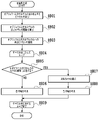
図7は、データ取得手順例を示すフローチャートである。具体的には、フロントエンドサーバ230がセンサシステム110からデータを受信し、各種データを書き込むまでの手順を示したフローチャートである。以降、フローチャートに従い、処理のフローを説明する。なお、以下のフローの説明において、記号「S」はステップを表す。フロントエンドサーバ230は、例えば、DB250などからカメラパラメータを予め取得しているものとする。
FIG. 7 is a flow chart showing an example of a data acquisition procedure. Specifically, it is a flow chart showing a procedure from reception of data from the
S701では、画像入力部231は、センサシステム110からスイッチングハブ180を介して前景画像と背景画像を受信する。画像入力部231は、受信した背景画像をデータ書き込み部234に出力し、受信した前景画像をモデル生成部232と色情報生成部233に出力する。
In S<b>701 , the
S702では、モデル生成部232は、画像入力部231から入力された前景画像と予め設定されたカメラパラメータとに基づいて、Visual Hull方式等を用いてオブジェクト三次元モデルを生成する。そして、モデル生成部232は、生成したオブジェクト三次元モデルを色情報生成部233とデータ書き込み部234に出力する。
In S702, the
S703では、色情報生成部233は、入力されたオブジェクト三次元モデルおよび前景画像と予め設定されたカメラパラメータに基づいて、オブジェクト三次元モデルの色情報を生成する。そして、色情報生成部233は、オブジェクト三次元モデルの色情報をデータ書き込み部234に出力する。オブジェクト三次元モデルの色情報生成手順例の詳細については後述する。
In S703, the color
S704では、データ書き込み部234は、入力された、オブジェクト三次元モデルとオブジェクト三次元モデルの色情報と背景画像をDB250に書き込む。
In S<b>704 , the
以上が、フロントエンドサーバ230における、仮想視点画像を生成するための素材データの取得のフローである。
The above is the flow of acquisition of material data for generating a virtual viewpoint image in the front-
(S703の詳細)
次に、S703の詳細である、色情報生成部233で実行される色情報生成手順例について、図8を参照して説明する。
(Details of S703)
Next, an example of the color information generation procedure executed by the color
図8は、色情報生成手順例を示すフローチャートである。以降、フローチャートに従い、処理のフローを説明する。 FIG. 8 is a flow chart showing an example of a color information generation procedure. Hereinafter, the flow of processing will be described according to the flowchart.
S801では、色情報生成部233は、予め設定されたカメラパラメータとオブジェクト三次元モデルの点座標とに基づく幾何計算により、カメラで撮像された画像にて、点座標と対応するピクセルを導出する。具体的には、色情報生成部233は、オブジェクト三次元モデルの各点を、カメラで撮像された画像上に投影し、該各点と対応するピクセルの座標を導出する。すなわち、S801では、カメラの画像から、オブジェクト三次元モデルの点座標と対応するピクセルが抽出される。
In S801, the color
S802では、色情報生成部233は、カメラパラメータとオブジェクト三次元モデルの点座標に基づいて、オブジェクト三次元モデルの点とカメラとの距離を導出する。
In S802, the color
S803では、色情報生成部233は、S801で導出した、各カメラの画像のピクセル毎に、S802で導出した距離に基づいて、最も近くにある、オブジェクト三次元モデルの点を導出する。そして、色情報生成部233は、最も近くにある点に、該ピクセルのオブジェクト三次元モデルの色情報を生成するための対応ピクセルとして登録する。すなわち、オブジェクト三次元モデルのすべての点について、オブジェクト三次元モデルの色情報となり得るピクセルを、各カメラの画像から抽出して、対応ピクセルとして登録する。
In S803, the color
以降、S804~S809において、オブジェクト三次元モデルのすべての点について、点毎に色情報を生成する処理を実行する。すなわち、S804において、オブジェクト三次元モデルのすべての点に対してループ処理が開始される。 Thereafter, in steps S804 to S809, processing for generating color information for each point is executed for all points of the three-dimensional object model. That is, in S804, loop processing is started for all points of the three-dimensional model of the object.
S805では、S803で登録された対応ピクセルについて、対応ピクセルが存在する画像を撮像したカメラが2台以上あるかを判定する。すなわち、S803で登録された対応ピクセルについて、対応ピクセルが2台以上のカメラの画像に存在するかを判定する。 In S805, for the corresponding pixels registered in S803, it is determined whether or not there are two or more cameras that captured images in which the corresponding pixels exist. That is, for the corresponding pixels registered in S803, it is determined whether the corresponding pixels exist in the images of two or more cameras.
オブジェクト三次元モデルの点について登録された対応ピクセルが、1台のカメラの画像に存在する場合(S805:NO)、そのカメラの画像に存在する対応ピクセルの画素値から色情報を生成する(S806)。そのカメラの画像に存在する対応ピクセルが1つだけの場合は、その対応ピクセルの画素値を色情報として生成し、そのカメラの画像に存在する対応ピクセルが複数の場合には、複数の対応ピクセルの画素値の平均値を色情報として生成する。 If the corresponding pixels registered for the points of the three-dimensional model of the object exist in the image of one camera (S805: NO), color information is generated from the pixel values of the corresponding pixels in the image of that camera (S806). ). If there is only one corresponding pixel in the camera image, the pixel value of that corresponding pixel is generated as color information, and if there are multiple corresponding pixels in the camera image, multiple corresponding pixels is generated as color information.
他方、オブジェクト三次元モデルの点について登録された対応ピクセルが、2台以上(複数台)のカメラの画像に存在する場合には(S805:YES)、色情報を生成するための対象のカメラを1台選択する(S807)。なお、カメラ選択方法は、後述する。そして、選択したカメラの画像に存在する対応ピクセルの画素値に基づき、色情報を生成する(S808)。その後、S809に進み、すべての点に対する処理が終了した場合、S804からS809のループ処理を終了し、色情報生成処理が終了することとなる。なお、S806,S808にて生成した色情報は、上述のS704にて点と関連付けて記録される。 On the other hand, if the corresponding pixels registered for the points of the object three-dimensional model exist in the images of two or more (multiple) cameras (S805: YES), the target camera for generating color information is selected. One unit is selected (S807). A camera selection method will be described later. Then, color information is generated based on the pixel values of the corresponding pixels present in the image of the selected camera (S808). After that, the process proceeds to S809, and when the processing for all the points is completed, the loop processing from S804 to S809 is completed, and the color information generation processing is completed. Note that the color information generated in S806 and S808 is recorded in association with the point in S704 described above.
ここで、カメラ選択方法および色情報生成方法について、図9を参照して説明する。 Here, the camera selection method and the color information generation method will be described with reference to FIG.
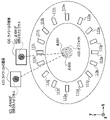
図9は、オブジェクト(オブジェクト三次元モデル)の周囲に16台のカメラが配置されたスタジアムを真上から俯瞰した図である。オブジェクト400を形成する点のうち、点4000について、色情報生成処理を行う場合について、具体的に説明する。S801~S803の処理を行い、オブジェクト400の点4000について、対応ピクセルが存在する画像を撮像したカメラは黒く塗られたカメラ、カメラ112f~カメラ112jの5台であったとする。
FIG. 9 is an overhead view of a stadium in which 16 cameras are arranged around an object (object three-dimensional model). Of the points that form the object 400, the case where the color information generation process is performed for the
まず、対応ピクセルのある画像を撮像したカメラのうち、最も外側にある2台のカメラが選択される。ここで最も外側にある2台のカメラとは、撮像対象の点4000を中心とし複数のカメラが隣接する方向を周方向とした場合に、該周方向で両端にあるカメラを示している。図9の例では、カメラ112fとカメラ112jが最も外側にある2台のカメラに該当することになる。
First, the two outermost cameras are selected from among the cameras that captured images with corresponding pixels. Here, the two outermost cameras refer to the cameras at both ends in the circumferential direction when the direction in which a plurality of cameras are adjacent to each other around the
次に、カメラ112fおよび点4000を結ぶ線分とカメラ112jおよび点4000を結ぶ線分の成す角θの二等分線が設定され、該二等分線が通る位置に最も近いカメラが、色情報を生成するカメラとして選択される。すなわち、オブジェクトの要素と正対するカメラが、色情報の生成対象のカメラとして選択される。図9の例では、カメラ112hが選択されることになる。また、対応ピクセルのある画像を撮像したカメラが2台以上である場合は、予め決められた優先順位に従い、例えば、カメラ112a~112pの順に優先順位が高いと、優先順位の最も高いカメラが選択されることになる。
Next, a line segment connecting the
カメラの画像に存在する対応ピクセルが1つだけの場合は、該対応ピクセルの画素値を色情報として生成し、対応ピクセルが複数の場合は該複数の対応ピクセルの画素値の平均値を色情報として生成する(S808)。ここでは、点4000をカメラ112hの画像420に投影したときに対応するピクセル421のRGB値が色情報として生成される。
When there is only one corresponding pixel in the camera image, the pixel value of the corresponding pixel is generated as color information, and when there are multiple corresponding pixels, the average value of the pixel values of the corresponding pixels is used as the color information. (S808). Here, the RGB values of the pixel 421 corresponding to the projection of the
このようにして選択されたピクセルの値が点に関連付けて記録されることになる。 The value of the pixel selected in this way is recorded in association with the point.
ここでは、一例として上記色情報生成方法について説明したが、他の手法が用いられても良く、上記色情報生成方法に限定されるものではない。例えば、複数のカメラを選択して平均値を色情報としたり、または複数の対応ピクセルがある場合に、大きく値の異なるピクセルの画素値を除外した残りの平均値を色情報としたりしても良い。 Here, the color information generation method has been described as an example, but other methods may be used, and the method is not limited to the color information generation method described above. For example, if you select multiple cameras and use the average value as color information, or if there are multiple corresponding pixels, you can use the remaining average value after excluding the pixel values of pixels with large differences as color information. good.
以上、オブジェクト三次元モデルおよびその色情報をDB250に格納する方法について述べた。
A method for storing an object three-dimensional model and its color information in the
以降、格納されたオブジェクト三次元モデルおよびその色情報を読み出して、仮想視点画像を生成する方法について述べる。すなわち、バックエンドサーバ270の詳細な構成および動作について、説明する。
Hereinafter, a method of reading out the stored three-dimensional object model and its color information and generating a virtual viewpoint image will be described. That is, the detailed configuration and operation of the
<バックエンドサーバ270の構成>
図10は、バックエンドサーバ270の機能構成例を示すブロック図である。
<Configuration of
FIG. 10 is a block diagram showing a functional configuration example of the
視点入力部271は、エンドユーザ端末190や仮想カメラ操作UI330などを介して不図示のユーザによる仮想視点情報の入力を受け付け、仮想視点情報をデータ取得部272と仮想視点画像生成部274に出力する。仮想視点情報は、実際にはカメラが存在せず仮想視点に配置されると仮定した仮想カメラで仮想視点画像を撮像する時刻、仮想視点(仮想カメラ)の位置、仮想カメラの姿勢、仮想カメラの向き、仮想カメラの画角、焦点距離などを含む情報である。
The
データ取得部272は、入力された仮想視点情報に基づいて、DB250から、カメラが実際には存在しない仮想視点の仮想カメラから見えると推測されたオブジェクトに関するオブジェクト三次元モデルとその色情報を取得する。すなわち、データ取得部272は、仮想視点に配置された仮想カメラの画角内に存在すると推測されるオブジェクトに関するオブジェクト三次元モデルとその色情報を取得する。データ取得部272は、取得したこれらデータ、すなわち、オブジェクト三次元モデルおよびその色情報を色付け部273に出力する。また、データ取得部272は、DB250から背景画像を取得し、取得した背景画像を仮想視点画像生成部274に出力する。
Based on the input virtual viewpoint information, the
色付け部273は、オブジェクト三次元モデルの点に対応するオブジェクト三次元モデルの色情報に基づく色を当該点に付与し、色付きオブジェクト三次元モデルを生成する。色付け部273は、生成した色付きオブジェクト三次元モデルを仮想視点画像生成部274に出力する。
The
仮想視点画像生成部274は、入力された仮想視点情報、色付きオブジェクト三次元モデル、および背景画像に基づき、仮想視点の仮想カメラから見た前景画像および背景画像を生成し、それらを合成して仮想視点画像を生成する。仮想視点画像生成部274は、生成した仮想視点画像をエンドユーザ端末190に送信する。
The virtual viewpoint
(仮想視点画像生成手順例)
次に、バックエンドサーバ270で行われる仮想視点画像生成手順例について、図11を参照して説明する。
(Example of virtual viewpoint image generation procedure)
Next, an example of a virtual viewpoint image generation procedure performed by the
図11は、仮想視点画像生成手順例を示すフローチャートである。以降、フローチャートに従い、処理のフローを説明する。 FIG. 11 is a flowchart illustrating an example of a virtual viewpoint image generation procedure. Hereinafter, the flow of processing will be described according to the flowchart.
S1101では、視点入力部271は、エンドユーザ端末190などを介して不図示のユーザによる仮想視点情報の入力を受け付ける。そして、視点入力部271は、受け付けた仮想視点情報をデータ取得部272と仮想視点画像生成部274とに出力する。
In S1101, the
S1102では、データ取得部272は、前記入力された仮想視点情報に基づいて、DB250から、オブジェクト三次元モデルとその色情報を取得し、色付け部273に出力する。また、データ取得部272は、前記入力された仮想視点情報に基づいて、DB250から、背景画像を取得し、仮想視点画像生成部274に出力する。具体的には、データ取得部272は、仮想視点情報で指定された時刻に基づき、その時刻の撮像画像に対応する前景画像から生成されたオブジェクト三次元モデルとその色情報を取得し、出力する。また、データ取得部272は、仮想視点情報で指定された時刻に基づき、その時刻の撮像画像に対応する背景画像を取得し、出力する。
In S<b>1102 , the
S1103では、色付け部273は、前記入力されたオブジェクト三次元モデルとその色情報に基づいて、オブジェクト三次元モデルの各点に対応ピクセルの色(画素値)を付与し、色付きオブジェクト三次元モデルを生成する。さらに、色付け部273は、色付きオブジェクト三次元モデルを仮想視点画像生成部274に出力する。
In S1103, the
S1104では、仮想視点画像生成部274は、各ブロックから入力された、仮想視点情報、背景画像、および色付きオブジェクト三次元モデルに基づき、仮想視点画像を生成する。具体的には、仮想視点画像生成部274は、データ取得部272から入力された背景画像および、予め設定されたスタジアム三次元モデルに基づいて、仮想視点に配置されると仮定した仮想カメラで撮像した場合の背景画像を生成する。スタジアム三次元モデルは、世界座標空間における座標位置をもったメッシュモデルとする。予め設定された各カメラのカメラパラメータとスタジアム三次元モデルに基づいて、三次元座標変換により、各メッシュに合わせたテクスチャ画像を背景画像から生成し、貼りつけることで色付きスタジアム三次元モデルを生成する。さらに、仮想視点のカメラ位置、向きなどの情報に基づき、世界座標空間上に存在するスタジアム三次元モデルを仮想視点のカメラの画像座標に射影し、背景画像を生成する。
In S1104, the virtual viewpoint
また、仮想視点画像生成部274は、色付け部273から入力された色付きオブジェクト三次元モデルに基づいて、仮想視点の位置に配置されると仮定した仮想カメラで撮像した場合の前景画像を生成する。具体的には、仮想視点画像生成部274は、仮想視点のカメラ位置、向きなどの情報に基づき、世界座標空間上に存在する色付きオブジェクト三次元モデルの色をもった点を、仮想視点のカメラの画像座標に射影し、前景画像を生成する。
Based on the three-dimensional model of the colored object input from the
仮想視点画像生成部274は、生成した背景画像と前景画像を合成し、仮想視点画像を生成する。そして、仮想視点画像生成部274は、生成された仮想視点画像をエンドユーザ端末190に送信する。
The virtual
オブジェクト三次元モデルの点群について色情報を生成する色情報生成部233を用いて説明したが、これに限定されるものではない。例えば、オブジェクト三次元モデルがメッシュモデルである場合には、オブジェクト三次元モデルの各メッシュについてメッシュの画素分の色をもつ色情報を生成する色情報生成部とすることも可能である。
Although the color
以上のことから、本実施形態によれば、前景画像をDBに格納しないが、オブジェクト三次元モデルの各要素の色情報をDBに格納する。格納したオブジェクト三次元モデルの色情報を用いて仮想視点画像を生成することができる。よって、データ量を削減しながらも、仮想視点画像を得ることができるようになる。 As described above, according to this embodiment, the foreground image is not stored in the DB, but the color information of each element of the three-dimensional object model is stored in the DB. A virtual viewpoint image can be generated using the color information of the stored three-dimensional model of the object. Therefore, it is possible to obtain a virtual viewpoint image while reducing the amount of data.
例えば、カメラ台数を30台、画像サイズを3840×2160、画像フォーマットをRGB8bit、オブジェクト三次元モデルの点の数を1,000,000点、モデルの点座標を32bitで表現するとする。 For example, assume that the number of cameras is 30, the image size is 3840×2160, the image format is RGB 8 bits, the number of points of the three-dimensional object model is 1,000,000, and the model point coordinates are 32 bits.
従来の手法では、前景画像のサイズは、1920×1080×3×8×30=1,492,992,000(bit)=186.624(MB)(メガバイト)となる。 In the conventional method, the size of the foreground image is 1920×1080×3×8×30 = 1,492,992,000 (bits)=186.624 (MB) (megabytes).
本実施形態によると、前景画像のかわりにオブジェクト三次元モデルの色情報を生成する。そのオブジェクト三次元モデルの色情報のサイズは、1,000,000×3×32=96,000,000(bit)=12(MB)となる。 According to this embodiment, instead of the foreground image, color information of the 3D model of the object is generated. The size of the color information of the object three-dimensional model is 1,000,000*3*32=96,000,000 (bit)=12 (MB).
よって、本実施形態によれば、前記条件では、従来例と比べておよそ15分の1のデータサイズに低減することができる。 Therefore, according to the present embodiment, under the above conditions, the data size can be reduced to approximately 1/15 of that in the conventional example.
[実施形態2]
本実施形態に係る画像処理システムについて、以下に説明する。
[Embodiment 2]
An image processing system according to this embodiment will be described below.
本実施形態では、オブジェクト三次元モデルの色情報に加え、複数のカメラの画像に基づいて、色を補正するオブジェクト三次元モデルの色補正情報を生成し、生成した色補正情報をDBに格納し、仮想視点に応じて色を補正する方法について述べる。 In this embodiment, in addition to the color information of the three-dimensional object model, color correction information of the three-dimensional object model whose colors are to be corrected is generated based on images from a plurality of cameras, and the generated color correction information is stored in the DB. , describes a method for correcting colors according to a virtual viewpoint.
図12は、本実施形態におけるフロントエンドサーバ230の機能構成例を示すブロック図である。本実施形態では、実施形態1と同じブロックには同一符号を付与し、その説明を適宜省略する。
FIG. 12 is a block diagram showing a functional configuration example of the front-
画像入力部235は、実施形態1にて説明した画像入力部231の機能に加え、色補正情報生成部237に前景画像を出力する。
An
モデル生成部236は、実施形態1にて説明したモデル生成部232の機能に加え、色補正情報生成部237にオブジェクト三次元モデルを出力する。
The
色補正情報生成部237は、画像入力部235から入力された前景画像と、モデル生成部236から入力されたオブジェクト三次元モデルに基づき、オブジェクト三次元モデルの点毎に色補正情報を生成する。色補正情報の生成方法の詳細については後述する。色補正情報生成部237は、生成したオブジェクト三次元モデルの色補正情報をデータ書き込み部238に出力する。
Based on the foreground image input from the
データ書き込み部238は、実施形態1にて説明したデータ書き込み部238の機能に加え、オブジェクト三次元モデルの色補正情報をDB250に書き込む。
The
(データ取得手順例)
次に、本実施形態のフロントエンドサーバ230で行われる、仮想視点画像を生成するための素材データの取得手順例について、図13を参照して説明する。
(Example of data acquisition procedure)
Next, an example of a procedure for acquiring material data for generating a virtual viewpoint image, which is performed by the front-
図13は、データ取得手順例を示すフローチャートである。具体的には、フロントエンドサーバ230がセンサシステム110からデータを受信し、各種データを書き込むまでの手順を示したフローチャートである。以降、フローチャートに従い、処理のフローを説明する。なお、フロントエンドサーバ230は、例えば、DB250などからカメラパラメータを予め取得しているものとする。
FIG. 13 is a flow chart showing an example of a data acquisition procedure . Specifically, it is a flow chart showing a procedure from reception of data from the
S1301では、画像入力部235は、センサシステム110からスイッチングハブ180を介して前景画像と背景画像を受信する。画像入力部235は、受信した背景画像をデータ書き込み部238に出力する。また、画像入力部235は、受信した前景画像をモデル生成部236と色情報生成部233と色補正情報生成部237に出力する。
In S<b>1301 , the
S1302では、モデル生成部236は、画像入力部235から入力された前景画像と予め設定されたカメラパラメータとに基づいて、Visual Hull方式等を用いてオブジェクト三次元モデルを生成する。そして、モデル生成部236は、生成したオブジェクト三次元モデルを色情報生成部233と色補正情報生成部237とデータ書き込み部238に出力する。
In S1302, the
S703では、色情報生成部233は、実施形態1と同様の処理を行う。
In S703, the color
S1304では、色補正情報生成部237は、オブジェクト三次元モデルと複数のカメラの前景画像と予め設定されたカメラパラメータに基づいて、オブジェクト三次元モデルの点毎に色補正情報を生成する。色補正情報生成部237は、生成したオブジェクト三次元モデルの色補正情報をデータ書き込み部238に出力する。オブジェクト三次元モデルの色補正情報生成処理の詳細については後述する。
In S1304, the color correction
S1305では、データ書き込み部238は、入力された、オブジェクト三次元モデルとその色情報とオブジェクト三次元モデルの色補正情報と背景画像をDB250に書き込む。
In S1305, the
以上が、フロントエンドサーバ230における、仮想視点画像を生成するための素材データの取得のフローである。
The above is the flow of acquisition of material data for generating a virtual viewpoint image in the front-
(S1304の詳細)
次に、S1304の詳細である、色補正情報生成部237で実行される色補正情報生成手順例について、図14を参照して説明する。
(Details of S1304)
Next, an example of the color correction information generation procedure executed by the color correction
図14は、色補正情報生成手順例を示すフローチャートである。以降、フローチャートに従い、処理のフローを説明する。なお、S1401~S1403は、実施形態1における色情報生成処理のS801~S803と同じ処理であるため、その説明を省略する。 FIG. 14 is a flow chart showing an example of a procedure for generating color correction information. Hereinafter, the flow of processing will be described according to the flowchart. Note that S1401 to S1403 are the same processing as S801 to S803 of the color information generation processing in the first embodiment, so description thereof will be omitted.
S1404~S1409において、オブジェクト三次元モデルのすべての点について、点毎に色補正情報を生成する処理を実行する。すなわち、S1404において、オブジェクト三次元モデルのすべての点に対してループ処理が開始される。 In S1404 to S1409, processing for generating color correction information for each point is executed for all points of the three-dimensional object model. That is, in S1404, loop processing is started for all points of the three-dimensional model of the object.
S1405では、S1403で登録された対応ピクセルについて、対応ピクセルが存在する画像を撮像したカメラが2台以上あるかを判定する。すなわち、S1403で登録された対応ピクセルについて、対応ピクセルが2台以上のカメラの画像に存在するかを判定する。 In S1405, for the corresponding pixels registered in S1403, it is determined whether or not there are two or more cameras that captured images in which the corresponding pixels exist. That is, for the corresponding pixels registered in S1403, it is determined whether the corresponding pixels exist in the images of two or more cameras.
オブジェクト三次元モデルの色補正情報を生成する対象の点について登録された対応ピクセルが、1台のカメラの画像に存在する場合(S1405:NO)、オブジェクト三次元モデルの色補正情報の生成を行わない(S1406)。また、色補正情報が無いことを示す情報を付与しても良い。これは、色情報生成部233の処理において、そのカメラの画像に基づいて色情報が生成されており、その点についてはその色情報のみで色を決定すれば良く、オブジェクト三次元モデルの色補正情報が不要であるためである。
If the corresponding pixel registered for the point for which the color correction information of the object 3D model is to be generated exists in the image of one camera (S1405: NO), the color correction information of the object 3D model is generated. None (S1406). Also, information indicating that there is no color correction information may be added. This is because, in the processing of the color
他方、オブジェクト三次元モデルの色補正情報を生成する対象の点について登録された対応ピクセルが、2台以上(複数台)のカメラの画像に存在する場合には(S1405:YES)、色補正情報を生成するための対象のカメラを選択する(S1407)。 On the other hand, if the corresponding pixels registered for the points for which the color correction information of the three-dimensional object model is to be generated exist in the images of two or more cameras (a plurality of cameras) (S1405: YES), the color correction information is selected (S1407).
ここで、カメラ選択方法および色補正情報生成方法について、図15を参照して説明する。 Here, the camera selection method and the color correction information generation method will be described with reference to FIG.
図15は、オブジェクト(オブジェクト三次元モデル)の周囲に16台のカメラが配置されたスタジアムを真上から俯瞰した図である。オブジェクト400を形成する点のうち、点4000について、色補正情報生成処理を行う場合について、具体的に説明する。S1400~S1403の処理を行い、オブジェクト400の点4000について、対応ピクセルが存在する画像を撮像したカメラは黒く塗られたカメラ、カメラ112f~カメラ112jの5台であったとする。
FIG. 15 is an overhead view of a stadium in which 16 cameras are arranged around an object (object three-dimensional model). Of the points forming the object 400, the case where the color correction information generation process is performed for the
色情報生成手順例の場合と同様、対応ピクセルのある画像を撮像したカメラのうち、最も外側にある2台のカメラが選択される。ここで最も外側とは、撮像対象の点4000を中心とし複数のカメラが隣接する方向を周方向とした場合に、該周方向で両端にあるカメラを示している。図15の例では、カメラ112fとカメラ112jが最も外側にある2台のカメラに該当することになる。ここで、対応ピクセルのある画像を撮像したカメラが2台である場合は、その2つのカメラが選択されることになる。
As in the example of the color information generation procedure, the two outermost cameras are selected from among the cameras that captured images having corresponding pixels. Here, the term "outermost" refers to the cameras at both ends in the circumferential direction when the direction in which a plurality of cameras are adjacent to each other around the
図14に戻る。S1408では、選択されたカメラの画像に存在する対応ピクセルに基づき、オブジェクト三次元モデルの色補正情報を生成する。カメラの画像に存在する対応ピクセルが1つだけの場合は、該対応ピクセルの画素値を色補正情報として生成し、対応ピクセルが複数の場合は複数の対応ピクセルの画素値の平均値を色補正情報として生成する。その後、S1409に進み、すべての3次元形状データの点に対する処理が終了した場合、S1404からS1409のループ処理を終了し、色補正情報生成処理が終了することとなる。なお、S1406,S1408にて生成した色補正情報は、上述のS1305にて点と関連付けて記録される。 Return to FIG. At S1408, color correction information for the 3D model of the object is generated based on the corresponding pixels present in the image of the selected camera. When there is only one corresponding pixel in the camera image, the pixel value of the corresponding pixel is generated as color correction information, and when there are multiple corresponding pixels, the average value of the pixel values of the corresponding pixels is used for color correction. Generate as information. After that, the process advances to S1409, and when the processing for all the points of the three-dimensional shape data is completed, the loop processing from S1404 to S1409 is completed, and the color correction information generation processing is completed. Note that the color correction information generated in S1406 and S1408 is recorded in association with the points in S1305 described above.
このようして選択した対応ピクセルの画素値(ピクセル値)であるRGB値と、その対応ピクセルが存在する画像を撮像したカメラのカメラIDとが関連付けられた色補正情報として記録されることとなる。ここで、オブジェクト三次元モデルの色補正情報は、オブジェクト三次元モデルの各点の色補正を示す情報であり、例えば、図16に示すように、RGB値、カメラIDがオブジェクト三次元モデルの点と関連付けて記録される。また、各点座標IDは1フレームにおいて、各点について独立に定まるIDである。例えば1フレーム内で存在する点には、0から昇順でIDが付与される。また、各点座標IDにて示されるカメラIDは、その点の色補正情報を生成するために使用した画像を撮像したカメラのIDを示している。オブジェクト三次元モデルの色補正情報はその点の色補正に使用される色情報を示している。カメラIDとオブジェクト三次元モデルの色補正情報として、選択したカメラが2台の場合は2つ、1台の場合は1つの情報が記録される。図15の例においては、点4000の1つ目の色補正情報である、オブジェクト三次元モデルの色補正情報1は、カメラ112fの画像440に存在する対応ピクセル441の画素値に基づいて生成される。2つ目の色補正情報であるオブジェクト三次元モデルの色補正情報2はカメラ112jの画像450に存在する対応ピクセル451の画素値に基づいて生成される。
The pixel value (pixel value) of the corresponding pixel selected in this manner and the camera ID of the camera that captured the image in which the corresponding pixel exists are associated and recorded as color correction information. . Here, the color correction information of the object three-dimensional model is information indicating the color correction of each point of the object three-dimensional model. For example, as shown in FIG. recorded in association with Also, each point coordinate ID is an ID determined independently for each point in one frame. For example, points existing within one frame are given IDs in ascending order from 0. FIG. Also, the camera ID indicated by each point coordinate ID indicates the ID of the camera that captured the image used to generate the color correction information for that point. The color correction information of the object 3D model indicates the color information used for color correction of that point. As the camera ID and the color correction information of the three-dimensional object model, two pieces of information are recorded when two cameras are selected, and one piece of information is recorded when one camera is selected. In the example of FIG. 15, the
本実施形態では、一例として上記カメラ選択方法について説明したが、他の手法が用いられても良く、上記カメラ選択方法に限定されるものではない。例えば、カメラ位置情報に基づいてカメラのz座標の値に差のある2台を選択したりカメラの画像のピクセル値に応じて差の大きい2台を選択したりしても良い。 In the present embodiment, the above camera selection method has been described as an example, but other techniques may be used, and the camera selection method is not limited to the above. For example, two cameras having different z-coordinate values may be selected based on the camera position information, or two cameras having large differences may be selected according to the pixel values of the camera images.
また、カメラの選択台数を2台とした場合について説明したが、選択するカメラの台数は2台に限定されるものではなく、選択するカメラの台数を3台以上としても良い。また対応ピクセルを1つとした場合について説明したが、対応ピクセルを2つ以上としても良い。例えば、対応したピクセルの画素値をすべてオブジェクト三次元モデルの色補正情報として記録しても良い。ピクセルの値の差によって選択するカメラ台数を変更し、差が大きいほどカメラ台数を多くし、差が小さいほどカメラ台数を減らすというカメラ選択方法を用いても良い。 Also, the case where the number of cameras to be selected is two has been described, but the number of cameras to be selected is not limited to two, and the number of cameras to be selected may be three or more. Also, although the case where the number of corresponding pixels is one has been described, the number of corresponding pixels may be two or more. For example, all the pixel values of the corresponding pixels may be recorded as the color correction information of the three-dimensional object model. A camera selection method may be used in which the number of cameras to be selected is changed according to the difference in pixel values, and the number of cameras is increased as the difference increases, and the number of cameras decreases as the difference decreases.
またオブジェクト三次元モデルの色情報、オブジェクト三次元モデルの色補正情報の記録方法として、RGB値を記録する方法について説明したが、他の手法が用いられても良く、上記記録方法に限定されるものではない。例えば、オブジェクト三次元モデルの色情報としてY,Cb,Crを記録し、オブジェクト三次元モデルの色補正情報としてY,Cb,CrのうちY成分のみを記録し、太陽光による反射などの輝度変化のみを補正する方法としても良い。 Also, as a method of recording the color information of the three-dimensional object model and the color correction information of the three-dimensional object model, a method of recording RGB values has been described, but other methods may be used, and the recording method is limited to the above. not a thing For example, Y, Cb, and Cr are recorded as color information of the three-dimensional object model, and only the Y component among Y, Cb, and Cr is recorded as color correction information of the three-dimensional object model. It is good also as a method of correcting only.
以上、オブジェクト三次元モデルおよびその色情報をDB250に格納する方法について述べた。
A method for storing an object three-dimensional model and its color information in the
以降、格納されたオブジェクト三次元モデルおよびその色情報、その色補正情報を読み出して、仮想視点画像を生成する方法について述べる。すなわち、バックエンドサーバ270の詳細な構成および動作について、説明する。
Hereinafter, a method of reading out the stored three-dimensional object model, its color information, and its color correction information and generating a virtual viewpoint image will be described. That is, the detailed configuration and operation of the
<バックエンドサーバ270の構成>
図17は、バックエンドサーバ270の機能構成例を示すブロック図である。
<Configuration of
FIG. 17 is a block diagram showing a functional configuration example of the
視点入力部275は、エンドユーザ端末190や仮想カメラ操作UI330などを介して不図示のユーザによる仮想視点情報の入力を受け付ける。視点入力部275は、受け付けた仮想視点情報をデータ取得部276および仮想視点画像生成部274と色補正部277とに出力する。
The
データ取得部276は、入力された仮想視点情報に基づいて、DB250から、カメラが実際には存在しない仮想視点の仮想カメラから見えると推測されたオブジェクトに関するオブジェクト三次元モデルとその色情報および色補正情報を取得する。すなわち、データ取得部276は、仮想視点に配置された仮想カメラの画角内に存在すると推測されるオブジェクトに関するオブジェクト三次元モデルとその色情報および色補正情報を取得する。データ取得部276は、取得したこれらデータ、すなわち、オブジェクト三次元モデルとその色情報および色補正情報を色補正部277に出力する。また、データ取得部276は、DB250から背景画像を取得し、取得した背景画像を仮想視点画像生成部274に出力する。
Based on the input virtual viewpoint information, the data acquisition unit 276 obtains from the
色補正部277は、オブジェクト三次元モデルとその色情報および色補正情報、仮想視点情報に基づき、オブジェクト三次元モデルの色情報を補正する。さらに、色補正部277は、補正後のオブジェクト三次元モデルの色情報を色付け部273に出力する。
The color correction unit 277 corrects the color information of the object three-dimensional model based on the object three-dimensional model, its color information, color correction information, and virtual viewpoint information. Furthermore, the color correcting section 277 outputs the corrected color information of the three-dimensional object model to the
ここで、色補正部277による色補正処理について、図18を参照して説明する。 Here, the color correction processing by the color correction section 277 will be described with reference to FIG. 18 .
色補正部277は、オブジェクト三次元モデルの色情報、オブジェクト三次元モデルの色補正情報に関連付いたカメラIDおよび予め設定されたカメラパラメータに応じて、それぞれの情報を生成する対象となったカメラの位置を導出する。 The color correction unit 277 selects a camera for which information is generated according to the color information of the three-dimensional object model, the camera ID associated with the color correction information of the three-dimensional object model, and preset camera parameters. Derive the position of
図18は、色補正処理方法を説明するための図である。具体的には、導出したカメラとオブジェクトの点4000の位置関係を示し、オブジェクト三次元モデルの色情報、オブジェクト三次元モデルの色補正情報を導出するために使用されたカメラの俯瞰図である。本来はz軸も加味するが、簡単のためx、y軸平面において説明する。
FIG. 18 is a diagram for explaining the color correction processing method. Specifically, it shows the positional relationship between the derived camera and the
ここでは、点4000に関し、色情報を補正する対象とした例について説明する。点4000における色情報の生成対象となった画像を撮像したカメラをカメラ(以下、色情報対象カメラともいう)510とする。また、点4000における色補正情報の生成対象となった画像を撮像したカメラをカメラ(以下、色補正情報対象カメラともいう)520、521とする。さらにユーザから指定された仮想視点と同様の位置を示す仮想カメラを仮想カメラ500、501とする。
Here, an example in which the color information of the
まず、仮想カメラ500が、色情報対象カメラ510と色補正情報対象カメラ520の間に位置付けられた場合について説明する。すなわち、色情報対象カメラ510と色補正情報対象カメラ520と点4000とで囲まれる領域内に仮想カメラ500が位置付けられた場合について説明する。
First, the case where the virtual camera 500 is positioned between the color information target camera 510 and the color correction information target camera 520 will be described. That is, the case where the virtual camera 500 is positioned within the area surrounded by the color information target camera 510, the color correction information target camera 520, and the
仮想カメラ500および点4000を結ぶ法線と色情報対象カメラ510および点4000を結ぶ法線とのなす角を角θ1とし、仮想カメラ500および点4000を結ぶ法線と色補正情報対象カメラ520と点4000を結ぶ法線のなす角を角θ2とする。すなわち、仮想カメラ500およびオブジェクトの要素である点4000を結ぶ法線に対し、色情報対象カメラ510の撮像方向とのなす角を角θ1とし、色補正情報対象カメラ520の撮像方向とのなす角を角θ2とする。
The angle between the normal connecting the virtual camera 500 and the
また、色情報をR1,G1,B1とし、対象となるカメラ520と関連付いた色補正情報をR2,G2,B2とする。この場合、補正後の色情報R1´、G1´、B1´は下記の演算式(1)~(3)により導出される。 Also, R1, G1, and B1 are color information, and R2, G2, and B2 are color correction information associated with the target camera 520 . In this case, the corrected color information R1′, G1′, and B1′ are derived from the following arithmetic expressions (1) to (3).
![]()
![]()
![]()
![]()
![]()
![]()
すなわち、仮想カメラ500および点4000を結ぶ法線と色情報対象カメラ510および色補正情報対象カメラ520それぞれの撮像方向とでなす角度の大きさに応じて、前記色情報と前記色補正情報の重みづけが設定される。
That is, the color information and the color correction information are weighted according to the magnitude of the angle formed by the normal line connecting the virtual camera 500 and the
また、仮想カメラ501のように、色情報対象カメラ510からみて、色補正情報対象カメラ520、521より外側の角度に仮想カメラが位置付けられた場合、以下のように色情報が設定される。すなわち、色補正情報対象カメラ520と色補正情報対象カメラ521と点4000とで囲まれる領域の外側の領域に仮想カメラ501が位置付けられた場合、以下のように色情報が設定される。仮想カメラ501に最も近接する色補正情報対象カメラ520と関連付いた色補正情報を補正後の色情報とする。すなわち、R1´=R2、G1´=G2、B1´=B2となる。
Also, like the virtual camera 501, when the virtual camera is positioned at an angle outside the color correction information target cameras 520 and 521 when viewed from the color information target camera 510, the color information is set as follows. That is, when the virtual camera 501 is positioned outside the area surrounded by the color correction information target camera 520, the color correction information target camera 521, and the
以上の補正処理をオブジェクト三次元モデルのすべての点について実行し、色情報を補正する。ここで、色補正情報がY成分のみである場合には、上述と同様に、Y成分のみを対象となるカメラのなす角に基づいて導出すれば良い。これは、見え方が物体の色(色差)は変わらず、光線の強さに依存することに基づいているためである。 The above correction processing is executed for all points of the three-dimensional object model to correct the color information. Here, when the color correction information is only the Y component, it suffices to derive only the Y component based on the angle formed by the target camera in the same manner as described above. This is because the appearance is based on the fact that the color of the object (color difference) does not change and depends on the intensity of the light.
本実施形態では、色補正方法の一例として角度を用いる方法について説明したが、他の手法を用いても良く、上記色補正方法に限定されるものではない。例えば、点とカメラの距離などによる重みづけを行い、重みづけに応じた色補正を行う手法を用いても良い。 In this embodiment, a method using an angle has been described as an example of the color correction method, but other methods may be used, and the color correction method is not limited to the above. For example, a method may be used in which weighting is performed according to the distance between the point and the camera, and color correction is performed according to the weighting.
(仮想視点画像生成手順例)
次に、バックエンドサーバ270で行われる仮想視点画像生成手順例について、図19を参照して説明する。
(Example of virtual viewpoint image generation procedure)
Next, an example of a virtual viewpoint image generation procedure performed by the
図19は、仮想視点画像生成手順例を示すフローチャートである。以降、フローチャートに従い、処理のフローを説明する。 FIG. 19 is a flowchart illustrating an example of a virtual viewpoint image generation procedure. Hereinafter, the flow of processing will be described according to the flowchart.
S1901では、視点入力部275は、エンドユーザ端末190などを介して不図示のユーザによる仮想視点情報の入力を受け付ける。そして、視点入力部275は、受け付けた仮想視点情報をデータ取得部276と仮想視点画像生成部274と色補正部277に出力する。
In S1901, the
S1902では、データ取得部276は、前記入力された仮想視点情報に基づいて、DB250から、オブジェクト三次元モデル、その色情報およびその色補正情報を取得し、色補正部277に出力する。また、データ取得部276は、前記入力された仮想視点情報に基づいて、DB250から、背景画像を取得し、仮想視点画像生成部274に出力する。具体的には、データ取得部276は、仮想視点情報で指定された時刻に基づき、その時刻の撮像画像に対応する前景画像から生成されたオブジェクト三次元モデル、その色情報および色補正情報を取得し、出力する。また、データ取得部276は、仮想視点情報で指定された時刻に基づき、その時刻の撮像画像に対応する背景画像を取得し、出力する。
In S<b>1902 , the data acquisition unit 276 acquires the three-dimensional object model, its color information, and its color correction information from the
S1903では、色補正部277は、前記入力された仮想視点情報とオブジェクト三次元モデルの色情報、オブジェクト三次元モデルの色補正情報に基づいて、オブジェクト三次元モデルの色情報を補正する。そして、色補正部277は、オブジェクト三次元モデルと、オブジェクト三次元モデルの色補正情報を色付け部273に出力する。
In S1903, the color correction unit 277 corrects the color information of the three-dimensional object model based on the input virtual viewpoint information, the color information of the three-dimensional object model, and the color correction information of the three-dimensional object model. The color correction section 277 then outputs the three-dimensional object model and the color correction information of the three-dimensional object model to the
S1904では、色付け部273は、入力されたオブジェクト三次元モデルと、補正後のオブジェクト三次元モデルの色情報に基づいて、オブジェクト三次元モデルの各点に対応ピクセルの色(画素値)を付与し、色付きオブジェクト三次元モデルを生成する。さらに、色付け部273は、色付きオブジェクト三次元モデルを仮想視点画像生成部274に出力する。
In S1904, the
S1905では、仮想視点画像生成部274は、実施形態1と同様、各ブロックから入力された、仮想視点情報、背景画像、および色付きオブジェクト三次元モデルに基づき、仮想視点画像を生成する。
In S1905, the virtual viewpoint
以上のことから、本実施形態によれば、前景画像をDBに格納しないが、オブジェクト三次元モデルの各要素の色情報に加え、色補正情報を格納する。これにより、格納したオブジェクト三次元モデルの色情報およびその色補正情報を用いて仮想視点画像を生成することができる。その結果、画質劣化を抑えた上で、DBに格納するデータ量を削減しながらも、仮想視点画像を得ることができるようになる。 As described above, according to this embodiment, the foreground image is not stored in the DB, but the color correction information is stored in addition to the color information of each element of the three-dimensional object model. Thus, a virtual viewpoint image can be generated using the stored color information of the three-dimensional model of the object and its color correction information. As a result, it is possible to obtain a virtual viewpoint image while suppressing deterioration in image quality and reducing the amount of data stored in the DB.
例えば、カメラ台数を30台、画像サイズを3840×2160、画像フォーマットをRGB8bit、オブジェクト三次元モデルの点の数を1,000,000点、モデルの点座標を32bitで表現するとする。 For example, assume that the number of cameras is 30, the image size is 3840×2160, the image format is RGB 8 bits, the number of points of the three-dimensional object model is 1,000,000, and the model point coordinates are 32 bits.
従来の手法では、前景画像のサイズは、1920×1080×3×8×30=1,492,992,000(bit)=186.624(MB)となる。 In the conventional method, the size of the foreground image is 1920×1080×3×8×30 = 1,492,992,000 (bit)=186.624 (MB).
本実施形態によると、前景画像のかわりにオブジェクト三次元モデルの色情報およびオブジェクト三次元モデルの色補正情報を生成する。そのオブジェクト三次元モデルの色情報のサイズは、1,000,000×3×32=96,000,000(bit)=12(MB)となる。 According to this embodiment, instead of the foreground image, the color information of the three-dimensional object model and the color correction information of the three-dimensional object model are generated. The size of the color information of the object three-dimensional model is 1,000,000*3*32=96,000,000 (bit)=12 (MB).
オブジェクト三次元モデルの色補正情報のサイズは、1,000,000×3×32×2=192,000,000(bit)=24(MB)となる。 The size of the color correction information of the three-dimensional object model is 1,000,000*3*32 *2 =192,000,000 (bit)=24 (MB).
前記オブジェクト三次元モデルの色情報とオブジェクト三次元モデルの色補正情報の合計は36(MB)となる。 The sum of the color information of the three-dimensional object model and the color correction information of the three-dimensional object model is 36 (MB).
よって、本実施形態によれば、前記条件では、従来例と比べておよそ5分の1のデータサイズに低減することができる。 Therefore, according to the present embodiment, under the above conditions, the data size can be reduced to approximately one-fifth of that in the conventional example.
[実施形態3]
本実施形態に係る画像処理システムについて、以下に説明する。
[Embodiment 3]
An image processing system according to this embodiment will be described below.
ここまで、従来例としてカメラの撮像画像から分離した前景画像を格納する方法、実施形態1としてオブジェクト三次元モデルの色情報を格納する方法、実施形態2としてさらにオブジェクト三次元モデルの色補正情報を格納する方法を説明した。 So far, a method of storing a foreground image separated from an image captured by a camera is stored as a conventional example, a method of storing color information of a three-dimensional object model is stored as a first embodiment, and color correction information of a three-dimensional object model is stored as a second embodiment. Explained how to store
本実施形態では、データ量の大きさに応じて動的に上記格納方法を切り替える方法について述べる。これにより、DBへの書き込み帯域の制約に応じて、適切なデータサイズでデータを格納することが可能となる。 In this embodiment, a method for dynamically switching the storage method according to the amount of data will be described. As a result, data can be stored in an appropriate data size according to the write band restriction to the DB.
まず、画質およびデータサイズの観点で上述の各方法を比較すると、従来例である、前景画像を格納する方法では、高画質であり、データサイズが大きくなる。これに対して、実施形態1である、オブジェクト三次元モデルの色情報のみを格納する方法では、画質が低いが、データサイズが小さくなる。実施形態2である、オブジェクト三次元モデルの色補正情報を格納する方法では、従来例および実施形態1の中間の画質およびデータサイズとなる。 First, comparing the above-described methods in terms of image quality and data size, the conventional method of storing a foreground image provides high image quality and a large data size. On the other hand, in the method of storing only the color information of the object 3D model, which is the first embodiment, the image quality is low, but the data size is small. In the method of storing the color correction information of the object three-dimensional model, which is the second embodiment, the image quality and data size are intermediate between those of the conventional example and the first embodiment.
図20は、本実施形態におけるフロントエンドサーバ230の機能構成例を示すブロック図である。本実施形態では、実施形態1、2と同じブロックには同一符号を付与し、その説明を適宜省略する。
FIG. 20 is a block diagram showing a functional configuration example of the front-
画像入力部235とモデル生成部236と色情報生成部233と色補正情報生成部237の機能は、図12に示されるフロントエンドサーバ230と同じであるため、その説明を省略する。これら機能ブロック235、236、233、237の出力先は、データ書き込み部から保存形式決定部239に変更される。
The functions of the
保存形式決定部239は、予め設定された閾値(基準値)と前記入力されたデータのデータサイズを比較し、比較結果に応じて保存形式を決定し、決定した形式でデータをデータ書き込み部240に出力する。
The storage
ここで、保存形式は、例えば、下記の3つの形式をとる。
(1)オブジェクト三次元モデル、背景画像、前景画像
(2)オブジェクト三次元モデル、背景画像、オブジェクト三次元モデルの色情報、オブジェクト三次元モデルの色補正情報
(3)オブジェクト三次元モデル、背景画像、オブジェクト三次元モデルの色情報
Here, the storage format takes, for example, the following three formats.
(1) Object 3D model, background image, foreground image (2) Object 3D model, background image, color information of object 3D model, color correction information of object 3D model (3) Object 3D model, background image , the color information of the 3D model of the object
例えば、予め設定された1フレーム分のデータとして書き込み可能なデータサイズが10MB(メガバイト)とする。この場合、優先順を(1)、(2)、(3)の順番で低くなるとし、かつ書き込み可能なデータサイズを超えない形式を選択するとする。データサイズは、オブジェクト三次元モデルが5MB、前景画像が10MB、背景画像が1MB、オブジェクト三次元モデルの色情報が1MB、オブジェクト三次元モデルの色補正情報が2MBであるとする。保存形式(1)では、オブジェクト三次元モデル、前景画像および背景画像を書き込むので、データサイズの合計が16MBとなり、閾値の10MBを超えることになる。保存形式(2)では、オブジェクト三次元モデル、背景画像、オブジェクト三次元モデルの色情報、オブジェクト三次元モデルの色補正情報を書き込むので、データサイズの合計は9MBとなり、閾値の10MBより小さい数値となる。したがって、(2)の保存形式が選択されることになる。保存形式決定部239は選択された保存形式にしたがって、入力されたデータから該当するデータを選択し、選択したデータをデータ書き込み部240に出力する。なお、保存形式(3)では、オブジェクト三次元モデル、背景画像、オブジェクト三次元モデルの色情報を書き込むので、データサイズの合計は7MBとなる。保存形式(3)は閾値を超えないデータサイズとなるが、保存形式(2)と比べて優先順が低いことから、保存形式(3)は選択されないこととなる。
For example, it is assumed that the writable data size of preset data for one frame is 10 MB (megabytes). In this case, it is assumed that the order of priority is lowered in the order of (1), (2), and (3), and a format that does not exceed the writable data size is selected. The data size is 5 MB for the three-dimensional object model, 10 MB for the foreground image, 1 MB for the background image, 1 MB for the color information of the three-dimensional object model, and 2 MB for the color correction information of the three-dimensional object model. In the storage format (1), the three-dimensional object model, foreground image, and background image are written, so the total data size is 16 MB, which exceeds the threshold of 10 MB. In save format (2), the 3D object model, the background image, the color information of the 3D object model, and the color correction information of the 3D object model are written, so the total data size is 9MB, which is smaller than the threshold value of 10MB. Become. Therefore, the storage format of (2) is selected. The saving
データ書き込み部240は、前記保存形式決定部239から入力されたデータをDB250に書き込む。すなわち、データ書き込み部240は、保存形式決定部239に入力されたデータのデータサイズが閾値を超えない場合、前景画像をDB250に書き込むが、閾値を超えた場合には、前景画像をDB250に書き込まない。
The
以上のことから、本実施形態によれば、データの書き込み帯域を鑑みて、最適な形式でデータを書き込むことが可能であり、書き込み可能な最も高画質なデータを格納することができる。 As described above, according to the present embodiment, it is possible to write data in an optimum format in consideration of the data writing band, and to store writable data with the highest image quality.
続いて、本実施形態を構成する各装置のハードウェア構成について、より詳細に説明する。上述の通り、本実施形態では、フロントエンドサーバ230がFPGA及び/又はASICなどのハードウェアを実装し、これらのハードウェアによって、上述した各処理を実行する場合の例を中心に説明した。それはセンサシステム110内の各種装置や、カメラアダプタ120、DB250、バックエンドサーバ270、タイムサーバ290、及びコントローラ300についても同様である。しかしながら、上記装置のうち、少なくとも何れかが、例えばCPU、GPU、DSPなどを用い、ソフトウェア処理によって本実施形態の処理を実行するようにしても良い。
Next, the hardware configuration of each device constituting this embodiment will be described in more detail. As described above, in the present embodiment, the front-
図21は、図4に示した機能構成をソフトウェア処理によって実現するための、フロントエンドサーバ230のハードウェア構成例を示す図である。なお、カメラアダプタ120、DB250、バックエンドサーバ270、タイムサーバ290、制御ステーション310、仮想カメラ操作UI330、及びエンドユーザ端末190などの装置も、図21のハードウェア構成となりうる。フロントエンドサーバ230は、CPU2301、ROM2302、RAM2303、補助記憶装置2304、表示部2305、操作部2306、通信部2307、及びバス2308を有する。
FIG. 21 is a diagram showing a hardware configuration example of the front-
CPU2301は、ROM2302やRAM2303に格納されているコンピュータプログラムやデータを用いてフロントエンドサーバ230の全体を制御する。ROM2302は、変更を必要としないプログラムやパラメータを格納する。RAM2303は、補助記憶装置2304から供給されるプログラムやデータ、及び通信部2307を介して外部から供給されるデータなどを一時記憶する。補助記憶装置2304は、例えばハードディスクドライブ等で構成され、静止画や動画などのコンテンツデータを記憶する。
The
表示部2305は、例えば液晶ディスプレイ等で構成され、ユーザがフロントエンドサーバ230を操作するためのGUI(Graphical User Interface)などを表示する。操作部2306は、例えばキーボードやマウス等で構成され、ユーザによる操作を受けて各種の指示をCPU2301に入力する。通信部2307は、カメラアダプタ120やDB250などの外部の装置と通信を行う。例えば、フロントエンドサーバ230が外部の装置と有線で接続される場合には、LANケーブル等が通信部2307に接続される。なお、フロントエンドサーバ230が外部の装置と無線通信する機能を有する場合、通信部2307はアンテナを備える。バス2308は、フロントエンドサーバ230の各部を繋いで情報を伝達する。
The
なお、例えばフロントエンドサーバ230の処理のうち一部をFPGAで行い、別の一部の処理を、CPUを用いたソフトウェア処理によって実現するようにしても良い。また、図21に示したフロントエンドサーバ230の各構成要素は、単一の電子回路で構成されていてもよいし、複数の電子回路で構成されていてもよい。例えば、フロントエンドサーバ230は、CPU2301として動作する電子回路を複数備えていてもよい。これら複数の電子回路がCPU2301としての処理を並行して行うことで、フロントエンドサーバ230の処理速度を向上することができる。
Note that, for example, part of the processing of the front-
また、本実施形態では表示部2305と操作部2306はフロントエンドサーバ230の内部に存在するが、フロントエンドサーバ230は表示部2305及び操作部2306の少なくとも一方を備えていなくてもよい。また、表示部2305及び操作部2306の少なくとも一方がフロントエンドサーバ230の外部に別の装置として存在していて、CPU2301が、表示部2305を制御する表示制御部、及び操作部2306を制御する操作制御部として動作してもよい。
Also, in this embodiment, the
画像処理システム100内の他の装置についても同様である。また例えば、カメラアダプタ120、DB250、バックエンドサーバ270及びタイムサーバ290は表示部2305を備えず、制御ステーション310、仮想カメラ操作UI330及びエンドユーザ端末190は表示部2305を備えていてもよい。また、上述の実施形態は、画像処理システム100が競技場やコンサートホールなどの施設に設置される場合の例を中心に説明した。施設の他の例としては、例えば、遊園地、公園、競馬場、競輪場、カジノ、プール、スケートリンク、スキー場、ライブハウスなどがある。また、各種施設で行われるイベントは、屋内で行われるものであっても屋外で行われるものであっても良い。また、本実施形態における施設は、一時的に(期間限定で)建設される施設も含む。
Other devices in the
[その他の実施形態]
本発明は、上述の実施形態の1以上の機能を実現するプログラムを、ネットワーク又は記憶媒体を介してシステム又は装置に供給し、そのシステム又は装置のコンピュータにおける1つ以上のプロセッサーがプログラムを読出し実行する処理でも実現可能である。また、1以上の機能を実現する回路(例えば、ASIC)によっても実現可能である。
[Other embodiments]
The present invention supplies a program that implements one or more functions of the above-described embodiments to a system or device via a network or a storage medium, and one or more processors in the computer of the system or device reads and executes the program. It can also be realized by processing to It can also be implemented by a circuit (for example, ASIC) that implements one or more functions.
230 フロントエンドサーバ
232 モデル生成部
233 色情報生成部
270 バックエンドサーバ
273 色付け部
274 仮想視点画像生成部
230 front-
Claims (34)
前記複数の画像に基づいて、前記第1の生成手段により生成された前記三次元形状データの要素の色を示す色情報を生成する第2の生成手段と、
前記複数の画像に基づいて、前記第1の生成手段により生成された前記三次元形状データの要素の色を仮想視点に応じて補正するための色補正情報を生成する第3の生成手段と、
前記第1の生成手段により生成された前記三次元形状データと前記第2の生成手段により生成された前記色情報と、前記第3の生成手段により生成された色補正情報を関連付けて記憶手段に記憶させる記憶制御手段と、
を有する、ことを特徴とするデータ生成装置。 a first generation means for generating three-dimensional shape data representing the shape of an object based on a plurality of images captured by a plurality of imaging devices;
a second generating means for generating color information indicating colors of elements of the three-dimensional shape data generated by the first generating means, based on the plurality of images;
a third generating means for generating, based on the plurality of images, color correction information for correcting the colors of the elements of the three-dimensional shape data generated by the first generating means according to a virtual viewpoint;
The three-dimensional shape data generated by the first generation means, the color information generated by the second generation means, and the color correction information generated by the third generation means are associated with each other and stored in storage means. a memory control means for storing;
A data generation device characterized by comprising:
前記記憶制御手段は、前記決定手段により決定された前記データ形式で、前記三次元形状データと前記色情報と前記色補正情報を前記記憶手段に記憶させることを特徴とする請求項1から5の何れか一項に記載のデータ生成装置。 further comprising determining means for determining a data format of data stored in the storage means;
6. The method according to claim 1, wherein said storage control means causes said storage means to store said three-dimensional shape data, said color information, and said color correction information in said data format determined by said determination means. A data generator according to any one of claims 1 to 3.
前記決定手段は、前記三次元形状データと前記背景画像と前記前景画像の組、前記三次元形状データと前記背景画像と前記色情報と前記色補正情報の組、前記三次元形状データと前記背景画像と前記色情報の組のうち、前記基準値を満たす組を前記データ形式として決定する
ことを特徴とする請求項7に記載のデータ生成装置。 generating a foreground image containing objects and a background image without objects based on the plurality of images;
The determining means includes a set of the three-dimensional shape data, the background image, and the foreground image, a set of the three-dimensional shape data, the background image, the color information, and the color correction information, and the three-dimensional shape data and the background. 8. The data generating apparatus according to claim 7, wherein, among the sets of the image and the color information, a set that satisfies the reference value is determined as the data format.
ことを特徴とする請求項1から10の何れか一項に記載のデータ生成装置。 11. The data generation device according to claim 1, wherein the elements of the three-dimensional shape data are polygons.
を有する、ことを特徴とする請求項1から12の何れか一項に記載のデータ生成装置。 fourth generation means for generating a virtual viewpoint image corresponding to the virtual viewpoint based on the three-dimensional shape data, the color information , and the color correction information;
13. The data generation device according to any one of claims 1 to 12, characterized by having:
ことを特徴とする請求項13に記載のデータ生成装置。 14. The data of claim 13, wherein the weighting of the color information and the color correction information used to determine colors of elements of the three-dimensional shape data is changed based on the virtual viewpoint. generator .
ことを特徴とする請求項14に記載のデータ生成装置。 the color correction information close to the virtual viewpoint when the virtual viewpoint is in an area outside an area surrounded by the imaging device for which each of the color information and the color correction information is generated and the elements of the three-dimensional shape data; 15. The data generation device according to claim 14, wherein the color of the element of the three-dimensional shape data is determined using the color correction information corresponding to the imaging device for which the data is generated.
前記複数の画像に基づいて、前記第1の生成ステップにて生成された前記三次元形状データの要素の色を示す色情報を生成する第2の生成ステップと、
前記複数の画像に基づいて、前記第1の生成ステップにて生成された前記三次元形状データの要素の色を仮想視点に応じて補正するための色補正情報を生成する第3の生成ステップと、
前記第1の生成ステップにて生成された前記三次元形状データと前記第2の生成ステップにて生成された前記色情報と、前記第3の生成ステップにて生成された色補正情報を関連付けて記憶手段に記憶させる記憶制御ステップと、
を含む、ことを特徴とするデータ生成方法。 a first generation step of generating three-dimensional shape data representing the shape of an object based on a plurality of images captured by a plurality of imaging devices;
a second generation step of generating color information indicating colors of elements of the three-dimensional shape data generated in the first generation step based on the plurality of images;
a third generation step of generating, based on the plurality of images, color correction information for correcting the colors of the elements of the three-dimensional shape data generated in the first generation step according to a virtual viewpoint; ,
The three-dimensional shape data generated in the first generation step, the color information generated in the second generation step, and the color correction information generated in the third generation step are associated with each other. a storage control step of storing in a storage means;
A data generation method, comprising:
前記複数の画像に基づいて、前記第1の生成手段により生成された前記三次元形状データの要素の色を示す色情報を生成する第2の生成手段と、a second generating means for generating color information indicating colors of elements of the three-dimensional shape data generated by the first generating means, based on the plurality of images;
前記複数の画像に基づいて、前記第1の生成手段により生成された前記三次元形状データの要素の色を仮想視点に応じて補正するための色補正情報を生成する第3の生成手段と、a third generating means for generating, based on the plurality of images, color correction information for correcting the colors of the elements of the three-dimensional shape data generated by the first generating means according to a virtual viewpoint;
を有するデータ生成装置と、a data generator having
前記データ生成装置の前記第1の生成手段により生成された前記三次元形状データと、前記データ生成装置の前記第2の生成手段により生成された前記色情報と、前記データ生成装置の前記第3の生成手段により生成された色補正情報を関連付けて記憶する記憶装置と、The three-dimensional shape data generated by the first generation means of the data generation device, the color information generated by the second generation means of the data generation device, and the third generation means of the data generation device a storage device that associates and stores the color correction information generated by the generation means of
を有する、ことを特徴とするシステム。A system characterized by comprising:
前記記憶装置は、前記決定手段により決定された前記データ形式で、前記三次元形状データと前記色情報と前記色補正情報を記憶することを特徴とする請求項19から23の何れか一項に記載のシステム。24. The method according to any one of claims 19 to 23, wherein said storage device stores said three-dimensional shape data, said color information, and said color correction information in said data format determined by said determining means. System as described.
前記決定手段は、前記三次元形状データと前記背景画像と前記前景画像の組、前記三次元形状データと前記背景画像と前記色情報と前記色補正情報の組、前記三次元形状データと前記背景画像と前記色情報の組のうち、前記基準値を満たす組を前記データ形式として決定するThe determining means includes a set of the three-dimensional shape data, the background image, and the foreground image, a set of the three-dimensional shape data, the background image, the color information, and the color correction information, and the three-dimensional shape data and the background. Among the pairs of the image and the color information, a pair that satisfies the reference value is determined as the data format.
ことを特徴とする請求項25に記載のシステム。26. The system of claim 25, wherein:
ことを特徴とする請求項19から28の何れか一項に記載のシステム。29. A system according to any one of claims 19 to 28, characterized in that:
ことを特徴とする請求項19から28の何れか一項に記載のシステム。29. A system according to any one of claims 19 to 28, characterized in that:
前記オブジェクトの形状を示す三次元形状データと、前記三次元形状データの要素の色を示す色情報と、前記三次元形状データの要素の色を前記仮想視点に応じて補正するための色補正情報と、を取得する第2の取得手段と、three-dimensional shape data indicating the shape of the object; color information indicating the color of the elements of the three-dimensional shape data; and color correction information for correcting the colors of the elements of the three-dimensional shape data according to the virtual viewpoint. and a second acquisition means for acquiring
前記第2の取得手段により取得された前記三次元形状データと前記色情報と前記色補正情報とに基づいて、前記第1の取得手段により取得された前記仮想視点情報により特定される仮想視点に対応する仮想視点画像を生成する画像生成手段と、を有する画像処理装置をBased on the three-dimensional shape data, the color information, and the color correction information acquired by the second acquisition means, a virtual viewpoint specified by the virtual viewpoint information acquired by the first acquisition means. and an image generating means for generating a corresponding virtual viewpoint image.
さらに有することを特徴とする請求項19から30の何れか一項に記載のシステム。31. The system of any one of claims 19-30, further comprising:
ことを特徴とする請求項31に記載のシステム。32. The system of claim 31, wherein:
ことを特徴とする請求項32に記載のシステム。33. The system of claim 32, wherein:
Priority Applications (4)
| Application Number | Priority Date | Filing Date | Title |
|---|---|---|---|
| JP2018111163A JP7187182B2 (en) | 2018-06-11 | 2018-06-11 | Data generator, method and program |
| US16/421,576 US11227429B2 (en) | 2018-06-11 | 2019-05-24 | Image processing apparatus, method and storage medium for generating a virtual viewpoint with reduced image data |
| KR1020190063549A KR102412242B1 (en) | 2018-06-11 | 2019-05-30 | Image processing apparatus, method and storage medium |
| RU2019117607A RU2727101C1 (en) | 2018-06-11 | 2019-06-06 | Image processing device, method and storage medium |
Applications Claiming Priority (1)
| Application Number | Priority Date | Filing Date | Title |
|---|---|---|---|
| JP2018111163A JP7187182B2 (en) | 2018-06-11 | 2018-06-11 | Data generator, method and program |
Publications (3)
| Publication Number | Publication Date |
|---|---|
| JP2019215622A JP2019215622A (en) | 2019-12-19 |
| JP2019215622A5 JP2019215622A5 (en) | 2021-07-26 |
| JP7187182B2 true JP7187182B2 (en) | 2022-12-12 |
Family
ID=68765221
Family Applications (1)
| Application Number | Title | Priority Date | Filing Date |
|---|---|---|---|
| JP2018111163A Active JP7187182B2 (en) | 2018-06-11 | 2018-06-11 | Data generator, method and program |
Country Status (4)
| Country | Link |
|---|---|
| US (1) | US11227429B2 (en) |
| JP (1) | JP7187182B2 (en) |
| KR (1) | KR102412242B1 (en) |
| RU (1) | RU2727101C1 (en) |
Families Citing this family (9)
| Publication number | Priority date | Publication date | Assignee | Title |
|---|---|---|---|---|
| JPWO2020129696A1 (en) * | 2018-12-21 | 2021-11-04 | ソニーグループ株式会社 | Information processing equipment, information processing methods, programs, and information processing systems |
| US20220198751A1 (en) * | 2019-03-15 | 2022-06-23 | Mimaki Engineering Co., Ltd. | Three-dimensional-body data generation device, three-dimensional-body data generation method, program, and modeling system |
| CN113574849A (en) * | 2019-07-29 | 2021-10-29 | 苹果公司 | Object scanning for subsequent object detection |
| US11107195B1 (en) | 2019-08-23 | 2021-08-31 | Lucasfilm Entertainment Company Ltd. | Motion blur and depth of field for immersive content production systems |
| JP2022160233A (en) * | 2021-04-06 | 2022-10-19 | キヤノン株式会社 | Information processing apparatus, information processing method, and program |
| US11978154B2 (en) | 2021-04-23 | 2024-05-07 | Lucasfilm Entertainment Company Ltd. | System and techniques for lighting adjustment for an immersive content production system |
| US11887251B2 (en) | 2021-04-23 | 2024-01-30 | Lucasfilm Entertainment Company Ltd. | System and techniques for patch color correction for an immersive content production system |
| JP7316693B2 (en) * | 2021-07-22 | 2023-07-28 | エフエックスギア インコーポレイティッド | 3D polygon mesh rendering method and apparatus using multi-viewpoint texture |
| JP2023128268A (en) * | 2022-03-03 | 2023-09-14 | キヤノン株式会社 | Information processing device, information processing method, image generation device, image generation method, and program |
Citations (2)
| Publication number | Priority date | Publication date | Assignee | Title |
|---|---|---|---|---|
| JP2016126425A (en) | 2014-12-26 | 2016-07-11 | Kddi株式会社 | Free viewpoint image generation device, method and program |
| JP2017227975A (en) | 2016-06-20 | 2017-12-28 | 株式会社Cygames | System for creating mixed reality environment |
Family Cites Families (26)
| Publication number | Priority date | Publication date | Assignee | Title |
|---|---|---|---|---|
| JP3286306B2 (en) * | 1998-07-31 | 2002-05-27 | 松下電器産業株式会社 | Image generation device and image generation method |
| EP1371019A2 (en) | 2001-01-26 | 2003-12-17 | Zaxel Systems, Inc. | Real-time virtual viewpoint in simulated reality environment |
| US7538774B2 (en) | 2003-06-20 | 2009-05-26 | Nippon Telegraph And Telephone Corporation | Virtual visual point image generating method and 3-d image display method and device |
| US7324594B2 (en) * | 2003-11-26 | 2008-01-29 | Mitsubishi Electric Research Laboratories, Inc. | Method for encoding and decoding free viewpoint videos |
| RU2282946C2 (en) | 2003-12-25 | 2006-08-27 | Александр Александрович Сухов | Method for transferring visual information |
| EP1862969A1 (en) * | 2006-06-02 | 2007-12-05 | Eidgenössische Technische Hochschule Zürich | Method and system for generating a representation of a dynamically changing 3D scene |
| JP4803594B2 (en) | 2006-07-05 | 2011-10-26 | Kddi株式会社 | Apparatus and program for generating free viewpoint image by local region segmentation |
| US8073190B2 (en) | 2007-11-16 | 2011-12-06 | Sportvision, Inc. | 3D textured objects for virtual viewpoint animations |
| US8817071B2 (en) * | 2009-11-17 | 2014-08-26 | Seiko Epson Corporation | Context constrained novel view interpolation |
| JP5812448B2 (en) | 2010-05-12 | 2015-11-11 | トムソン ライセンシングThomson Licensing | Unified significance map encoding method and apparatus |
| US8823797B2 (en) | 2010-06-03 | 2014-09-02 | Microsoft Corporation | Simulated video with extra viewpoints and enhanced resolution for traffic cameras |
| KR101666019B1 (en) * | 2010-08-03 | 2016-10-14 | 삼성전자주식회사 | Apparatus and method for generating extrapolated view |
| JP5858381B2 (en) * | 2010-12-03 | 2016-02-10 | 国立大学法人名古屋大学 | Multi-viewpoint image composition method and multi-viewpoint image composition system |
| US9171402B1 (en) * | 2013-06-19 | 2015-10-27 | Google Inc. | View-dependent textures for interactive geographic information system |
| JP6570296B2 (en) * | 2015-04-09 | 2019-09-04 | キヤノン株式会社 | Image processing apparatus, image processing method, and program |
| US9858640B1 (en) * | 2015-07-15 | 2018-01-02 | Hrl Laboratories, Llc | Device and method for merging 3D point clouds from sparsely distributed viewpoints |
| US10325402B1 (en) * | 2015-07-17 | 2019-06-18 | A9.Com, Inc. | View-dependent texture blending in 3-D rendering |
| JP6062589B1 (en) * | 2016-04-28 | 2017-01-18 | 株式会社Live2D | Program, information processing apparatus, influence derivation method, image generation method, and recording medium |
| US10204444B2 (en) * | 2016-04-28 | 2019-02-12 | Verizon Patent And Licensing Inc. | Methods and systems for creating and manipulating an individually-manipulable volumetric model of an object |
| US10055882B2 (en) * | 2016-08-15 | 2018-08-21 | Aquifi, Inc. | System and method for three-dimensional scanning and for capturing a bidirectional reflectance distribution function |
| US10559095B2 (en) * | 2016-08-31 | 2020-02-11 | Canon Kabushiki Kaisha | Image processing apparatus, image processing method, and medium |
| JP6988815B2 (en) | 2016-10-19 | 2022-01-05 | ソニーグループ株式会社 | Image processing device and image processing method |
| EP3565259A1 (en) * | 2016-12-28 | 2019-11-06 | Panasonic Intellectual Property Corporation of America | Three-dimensional model distribution method, three-dimensional model receiving method, three-dimensional model distribution device, and three-dimensional model receiving device |
| US10417810B2 (en) * | 2017-05-31 | 2019-09-17 | Verizon Patent And Licensing Inc. | Methods and systems for rendering virtual reality content based on two-dimensional (“2D”) captured imagery of a three-dimensional (“3D”) scene |
| US10297087B2 (en) * | 2017-05-31 | 2019-05-21 | Verizon Patent And Licensing Inc. | Methods and systems for generating a merged reality scene based on a virtual object and on a real-world object represented from different vantage points in different video data streams |
| US10930054B2 (en) * | 2019-06-18 | 2021-02-23 | Intel Corporation | Method and system of robust virtual view generation between camera views |
-
2018
- 2018-06-11 JP JP2018111163A patent/JP7187182B2/en active Active
-
2019
- 2019-05-24 US US16/421,576 patent/US11227429B2/en active Active
- 2019-05-30 KR KR1020190063549A patent/KR102412242B1/en active IP Right Grant
- 2019-06-06 RU RU2019117607A patent/RU2727101C1/en active
Patent Citations (2)
| Publication number | Priority date | Publication date | Assignee | Title |
|---|---|---|---|---|
| JP2016126425A (en) | 2014-12-26 | 2016-07-11 | Kddi株式会社 | Free viewpoint image generation device, method and program |
| JP2017227975A (en) | 2016-06-20 | 2017-12-28 | 株式会社Cygames | System for creating mixed reality environment |
Also Published As
| Publication number | Publication date |
|---|---|
| KR20190140396A (en) | 2019-12-19 |
| RU2727101C1 (en) | 2020-07-17 |
| JP2019215622A (en) | 2019-12-19 |
| US20190378326A1 (en) | 2019-12-12 |
| KR102412242B1 (en) | 2022-06-23 |
| US11227429B2 (en) | 2022-01-18 |
Similar Documents
| Publication | Publication Date | Title |
|---|---|---|
| JP7187182B2 (en) | Data generator, method and program | |
| US11217006B2 (en) | Methods and systems for performing 3D simulation based on a 2D video image | |
| JP7121470B2 (en) | Image processing system, control method, and program | |
| JP6429829B2 (en) | Image processing system, image processing apparatus, control method, and program | |
| KR102280587B1 (en) | System, method, and non-transitory computer readable storage medium for generating virtual viewpoint image | |
| JP6415675B1 (en) | Generating apparatus, generating method, and program | |
| US10812770B2 (en) | Image processing system, image processing apparatus, image processing method, and program | |
| JP7179515B2 (en) | Apparatus, control method and program | |
| US10755675B2 (en) | Image processing system, image processing method, and computer program | |
| JP2017212593A (en) | Information processing device, image processing system, information processing method, and program | |
| JP2017212592A (en) | Controller, control method, and program | |
| JP2017211827A (en) | Information processing unit, control method and program | |
| JP7042571B2 (en) | Image processing device and its control method, program | |
| JP2017212591A (en) | Control apparatus, control method, and program | |
| US20190132529A1 (en) | Image processing apparatus and image processing method | |
| US10623715B2 (en) | Information processing apparatus and control method therefor | |
| JP2019022151A (en) | Information processing apparatus, image processing system, control method, and program | |
| JP2019103126A (en) | Camera system, camera control device, camera control method, and program | |
| JP2020067815A (en) | Image processing system, image processing method, and program | |
| JP2019050593A (en) | Image processing system, image processor, control method, and program | |
| EP3742402B1 (en) | Generation of a virtual viewpoint image | |
| JP2022126205A (en) | Information processing apparatus, information processing method, and program | |
| JP2019075740A (en) | Image processing system, image processing apparatus, image transmission method, and program | |
| JP6759375B2 (en) | Systems, methods and programs that generate virtual viewpoint images | |
| EP4261788A1 (en) | Image processing apparatus, image processing method, and program |
Legal Events
| Date | Code | Title | Description |
|---|---|---|---|
| A521 | Request for written amendment filed |
Free format text: JAPANESE INTERMEDIATE CODE: A523 Effective date: 20210608 |
|
| A621 | Written request for application examination |
Free format text: JAPANESE INTERMEDIATE CODE: A621 Effective date: 20210608 |
|
| A977 | Report on retrieval |
Free format text: JAPANESE INTERMEDIATE CODE: A971007 Effective date: 20220711 |
|
| A131 | Notification of reasons for refusal |
Free format text: JAPANESE INTERMEDIATE CODE: A131 Effective date: 20220816 |
|
| A521 | Request for written amendment filed |
Free format text: JAPANESE INTERMEDIATE CODE: A523 Effective date: 20221012 |
|
| TRDD | Decision of grant or rejection written | ||
| A01 | Written decision to grant a patent or to grant a registration (utility model) |
Free format text: JAPANESE INTERMEDIATE CODE: A01 Effective date: 20221101 |
|
| A61 | First payment of annual fees (during grant procedure) |
Free format text: JAPANESE INTERMEDIATE CODE: A61 Effective date: 20221130 |
|
| R151 | Written notification of patent or utility model registration |
Ref document number: 7187182 Country of ref document: JP Free format text: JAPANESE INTERMEDIATE CODE: R151 |