JP7173060B2 - Vehicle control device - Google Patents
Vehicle control device Download PDFInfo
- Publication number
- JP7173060B2 JP7173060B2 JP2020005606A JP2020005606A JP7173060B2 JP 7173060 B2 JP7173060 B2 JP 7173060B2 JP 2020005606 A JP2020005606 A JP 2020005606A JP 2020005606 A JP2020005606 A JP 2020005606A JP 7173060 B2 JP7173060 B2 JP 7173060B2
- Authority
- JP
- Japan
- Prior art keywords
- vehicle
- height
- signal
- unit
- shaft
- Prior art date
- Legal status (The legal status is an assumption and is not a legal conclusion. Google has not performed a legal analysis and makes no representation as to the accuracy of the status listed.)
- Active
Links
- 239000000725 suspension Substances 0.000 claims description 36
- 239000006096 absorbing agent Substances 0.000 description 2
- 230000035939 shock Effects 0.000 description 2
- 238000005516 engineering process Methods 0.000 description 1
- 230000006870 function Effects 0.000 description 1
- 230000010365 information processing Effects 0.000 description 1
Images


Classifications
-
- B—PERFORMING OPERATIONS; TRANSPORTING
- B60—VEHICLES IN GENERAL
- B60W—CONJOINT CONTROL OF VEHICLE SUB-UNITS OF DIFFERENT TYPE OR DIFFERENT FUNCTION; CONTROL SYSTEMS SPECIALLY ADAPTED FOR HYBRID VEHICLES; ROAD VEHICLE DRIVE CONTROL SYSTEMS FOR PURPOSES NOT RELATED TO THE CONTROL OF A PARTICULAR SUB-UNIT
- B60W30/00—Purposes of road vehicle drive control systems not related to the control of a particular sub-unit, e.g. of systems using conjoint control of vehicle sub-units, or advanced driver assistance systems for ensuring comfort, stability and safety or drive control systems for propelling or retarding the vehicle
- B60W30/02—Control of vehicle driving stability
- B60W30/045—Improving turning performance
-
- B—PERFORMING OPERATIONS; TRANSPORTING
- B60—VEHICLES IN GENERAL
- B60G—VEHICLE SUSPENSION ARRANGEMENTS
- B60G17/00—Resilient suspensions having means for adjusting the spring or vibration-damper characteristics, for regulating the distance between a supporting surface and a sprung part of vehicle or for locking suspension during use to meet varying vehicular or surface conditions, e.g. due to speed or load
- B60G17/015—Resilient suspensions having means for adjusting the spring or vibration-damper characteristics, for regulating the distance between a supporting surface and a sprung part of vehicle or for locking suspension during use to meet varying vehicular or surface conditions, e.g. due to speed or load the regulating means comprising electric or electronic elements
- B60G17/016—Resilient suspensions having means for adjusting the spring or vibration-damper characteristics, for regulating the distance between a supporting surface and a sprung part of vehicle or for locking suspension during use to meet varying vehicular or surface conditions, e.g. due to speed or load the regulating means comprising electric or electronic elements characterised by their responsiveness, when the vehicle is travelling, to specific motion, a specific condition, or driver input
- B60G17/0162—Resilient suspensions having means for adjusting the spring or vibration-damper characteristics, for regulating the distance between a supporting surface and a sprung part of vehicle or for locking suspension during use to meet varying vehicular or surface conditions, e.g. due to speed or load the regulating means comprising electric or electronic elements characterised by their responsiveness, when the vehicle is travelling, to specific motion, a specific condition, or driver input mainly during a motion involving steering operation, e.g. cornering, overtaking
-
- B—PERFORMING OPERATIONS; TRANSPORTING
- B60—VEHICLES IN GENERAL
- B60W—CONJOINT CONTROL OF VEHICLE SUB-UNITS OF DIFFERENT TYPE OR DIFFERENT FUNCTION; CONTROL SYSTEMS SPECIALLY ADAPTED FOR HYBRID VEHICLES; ROAD VEHICLE DRIVE CONTROL SYSTEMS FOR PURPOSES NOT RELATED TO THE CONTROL OF A PARTICULAR SUB-UNIT
- B60W10/00—Conjoint control of vehicle sub-units of different type or different function
- B60W10/22—Conjoint control of vehicle sub-units of different type or different function including control of suspension systems
-
- B60K35/10—
-
- B—PERFORMING OPERATIONS; TRANSPORTING
- B60—VEHICLES IN GENERAL
- B60W—CONJOINT CONTROL OF VEHICLE SUB-UNITS OF DIFFERENT TYPE OR DIFFERENT FUNCTION; CONTROL SYSTEMS SPECIALLY ADAPTED FOR HYBRID VEHICLES; ROAD VEHICLE DRIVE CONTROL SYSTEMS FOR PURPOSES NOT RELATED TO THE CONTROL OF A PARTICULAR SUB-UNIT
- B60W10/00—Conjoint control of vehicle sub-units of different type or different function
- B60W10/04—Conjoint control of vehicle sub-units of different type or different function including control of propulsion units
-
- B—PERFORMING OPERATIONS; TRANSPORTING
- B60—VEHICLES IN GENERAL
- B60W—CONJOINT CONTROL OF VEHICLE SUB-UNITS OF DIFFERENT TYPE OR DIFFERENT FUNCTION; CONTROL SYSTEMS SPECIALLY ADAPTED FOR HYBRID VEHICLES; ROAD VEHICLE DRIVE CONTROL SYSTEMS FOR PURPOSES NOT RELATED TO THE CONTROL OF A PARTICULAR SUB-UNIT
- B60W10/00—Conjoint control of vehicle sub-units of different type or different function
- B60W10/20—Conjoint control of vehicle sub-units of different type or different function including control of steering systems
-
- B—PERFORMING OPERATIONS; TRANSPORTING
- B62—LAND VEHICLES FOR TRAVELLING OTHERWISE THAN ON RAILS
- B62D—MOTOR VEHICLES; TRAILERS
- B62D1/00—Steering controls, i.e. means for initiating a change of direction of the vehicle
- B62D1/02—Steering controls, i.e. means for initiating a change of direction of the vehicle vehicle-mounted
- B62D1/04—Hand wheels
-
- B—PERFORMING OPERATIONS; TRANSPORTING
- B62—LAND VEHICLES FOR TRAVELLING OTHERWISE THAN ON RAILS
- B62D—MOTOR VEHICLES; TRAILERS
- B62D1/00—Steering controls, i.e. means for initiating a change of direction of the vehicle
- B62D1/02—Steering controls, i.e. means for initiating a change of direction of the vehicle vehicle-mounted
- B62D1/12—Hand levers
-
- B—PERFORMING OPERATIONS; TRANSPORTING
- B60—VEHICLES IN GENERAL
- B60G—VEHICLE SUSPENSION ARRANGEMENTS
- B60G2204/00—Indexing codes related to suspensions per se or to auxiliary parts
- B60G2204/62—Adjustable continuously, e.g. during driving
-
- B—PERFORMING OPERATIONS; TRANSPORTING
- B60—VEHICLES IN GENERAL
- B60G—VEHICLE SUSPENSION ARRANGEMENTS
- B60G2300/00—Indexing codes relating to the type of vehicle
- B60G2300/45—Rolling frame vehicles
-
- B—PERFORMING OPERATIONS; TRANSPORTING
- B60—VEHICLES IN GENERAL
- B60G—VEHICLE SUSPENSION ARRANGEMENTS
- B60G2400/00—Indexing codes relating to detected, measured or calculated conditions or factors
- B60G2400/40—Steering conditions
-
- B—PERFORMING OPERATIONS; TRANSPORTING
- B60—VEHICLES IN GENERAL
- B60G—VEHICLE SUSPENSION ARRANGEMENTS
- B60G2600/00—Indexing codes relating to particular elements, systems or processes used on suspension systems or suspension control systems
- B60G2600/20—Manual control or setting means
-
- B—PERFORMING OPERATIONS; TRANSPORTING
- B60—VEHICLES IN GENERAL
- B60G—VEHICLE SUSPENSION ARRANGEMENTS
- B60G2800/00—Indexing codes relating to the type of movement or to the condition of the vehicle and to the end result to be achieved by the control action
- B60G2800/01—Attitude or posture control
- B60G2800/012—Rolling condition
-
- B—PERFORMING OPERATIONS; TRANSPORTING
- B60—VEHICLES IN GENERAL
- B60G—VEHICLE SUSPENSION ARRANGEMENTS
- B60G2800/00—Indexing codes relating to the type of movement or to the condition of the vehicle and to the end result to be achieved by the control action
- B60G2800/01—Attitude or posture control
- B60G2800/014—Pitch; Nose dive
-
- B60K2360/133—
-
- B—PERFORMING OPERATIONS; TRANSPORTING
- B60—VEHICLES IN GENERAL
- B60W—CONJOINT CONTROL OF VEHICLE SUB-UNITS OF DIFFERENT TYPE OR DIFFERENT FUNCTION; CONTROL SYSTEMS SPECIALLY ADAPTED FOR HYBRID VEHICLES; ROAD VEHICLE DRIVE CONTROL SYSTEMS FOR PURPOSES NOT RELATED TO THE CONTROL OF A PARTICULAR SUB-UNIT
- B60W2520/00—Input parameters relating to overall vehicle dynamics
- B60W2520/16—Pitch
-
- B—PERFORMING OPERATIONS; TRANSPORTING
- B60—VEHICLES IN GENERAL
- B60W—CONJOINT CONTROL OF VEHICLE SUB-UNITS OF DIFFERENT TYPE OR DIFFERENT FUNCTION; CONTROL SYSTEMS SPECIALLY ADAPTED FOR HYBRID VEHICLES; ROAD VEHICLE DRIVE CONTROL SYSTEMS FOR PURPOSES NOT RELATED TO THE CONTROL OF A PARTICULAR SUB-UNIT
- B60W2520/00—Input parameters relating to overall vehicle dynamics
- B60W2520/18—Roll
-
- B—PERFORMING OPERATIONS; TRANSPORTING
- B60—VEHICLES IN GENERAL
- B60W—CONJOINT CONTROL OF VEHICLE SUB-UNITS OF DIFFERENT TYPE OR DIFFERENT FUNCTION; CONTROL SYSTEMS SPECIALLY ADAPTED FOR HYBRID VEHICLES; ROAD VEHICLE DRIVE CONTROL SYSTEMS FOR PURPOSES NOT RELATED TO THE CONTROL OF A PARTICULAR SUB-UNIT
- B60W2540/00—Input parameters relating to occupants
-
- B—PERFORMING OPERATIONS; TRANSPORTING
- B60—VEHICLES IN GENERAL
- B60W—CONJOINT CONTROL OF VEHICLE SUB-UNITS OF DIFFERENT TYPE OR DIFFERENT FUNCTION; CONTROL SYSTEMS SPECIALLY ADAPTED FOR HYBRID VEHICLES; ROAD VEHICLE DRIVE CONTROL SYSTEMS FOR PURPOSES NOT RELATED TO THE CONTROL OF A PARTICULAR SUB-UNIT
- B60W2720/00—Output or target parameters relating to overall vehicle dynamics
- B60W2720/16—Pitch
-
- B—PERFORMING OPERATIONS; TRANSPORTING
- B60—VEHICLES IN GENERAL
- B60W—CONJOINT CONTROL OF VEHICLE SUB-UNITS OF DIFFERENT TYPE OR DIFFERENT FUNCTION; CONTROL SYSTEMS SPECIALLY ADAPTED FOR HYBRID VEHICLES; ROAD VEHICLE DRIVE CONTROL SYSTEMS FOR PURPOSES NOT RELATED TO THE CONTROL OF A PARTICULAR SUB-UNIT
- B60W2720/00—Output or target parameters relating to overall vehicle dynamics
- B60W2720/18—Roll
Description
本発明は、新たな機能を備えた車両用操縦装置に関する。 BACKGROUND OF THE INVENTION 1. Field of the Invention The present invention relates to a vehicle operating device with new functions.
近年、車両の状態に応じて車両を自動制御し、車両の操縦安定性を図ることが提案されている。例えば、エアサスペンションユニットを用いた車両において、前後の車輪の荷重が変化した際にエアサスペンションユニットのばね定数を変化させて車高を一定に保ちロール剛性を高くして車両操縦安定性を図ることが提案されている(例えば、特許文献1参照)。 2. Description of the Related Art In recent years, it has been proposed to automatically control a vehicle in accordance with the state of the vehicle to improve the steering stability of the vehicle. For example, in a vehicle using an air suspension unit, when the load on the front and rear wheels changes, the spring constant of the air suspension unit is changed to keep the vehicle height constant and increase the roll rigidity to improve vehicle steering stability. has been proposed (see, for example, Patent Document 1).
ところで、車両との一体感のあるドライビングを楽しみたいという要望がある。ところが、特許文献1に記載された従来技術では、ドライバの意図と関係なく車両を自動制御して操縦安定性を図るので、ドライバが車両との一体感を感じられない場合が多い。 By the way, there is a desire to enjoy driving with a sense of unity with the vehicle. However, in the conventional technology described in Patent Document 1, the vehicle is automatically controlled to achieve steering stability regardless of the driver's intention, so the driver often cannot feel a sense of unity with the vehicle.
そこで、本発明は、運転操作の際にドライバが車両との一体感を感じることができる車両用操縦装置を提供することを目的とする。 SUMMARY OF THE INVENTION Accordingly, it is an object of the present invention to provide a vehicle operating device that allows a driver to feel a sense of unity with the vehicle when driving.
本発明の車両用操縦装置は、ドライバが操作する操作部と、前記操作部の動きに応じて車両を旋回させると共に前記車両の高さを変化させる制御部と、を備える車両用操縦装置であって、前記制御部は、前記操作部の上下動に応じて前記車両の高さを変化させること、を特徴とする。 A vehicle operating device according to the present invention is a vehicle operating device comprising an operation unit operated by a driver, and a control unit for turning a vehicle and changing the height of the vehicle according to the movement of the operation unit. Further, the control unit changes the height of the vehicle according to the vertical movement of the operation unit.
これにより、ドライバの操作に基づいて車両の高さを変化させることができ、運転操作の際にドライバが車両との一体感を感じることができる。 As a result, the height of the vehicle can be changed based on the driver's operation, and the driver can feel a sense of unity with the vehicle during the driving operation.
本発明の車両用操縦装置において、前記車両は、前後左右の四輪をそれぞれ懸架するサスペンションユニットを備え、各サスペンションユニットは、それぞれ独立して高さを変更可能であり、前記制御部は、前記操作部の動きに応じて前記車両の左右のサスペンションユニットの高さ、又は、前記車両の前後のサスペンションユニットの高さを変化させて、前記車両のロール角、或いは、前記車両のピッチ角を変化させてもよい。 In the vehicle steering apparatus of the present invention, the vehicle includes suspension units for suspending four front, rear, left, and right wheels, each suspension unit being independently changeable in height. The roll angle of the vehicle or the pitch angle of the vehicle is changed by changing the height of the left and right suspension units of the vehicle or the height of the front and rear suspension units of the vehicle according to the movement of the operation part. You may let
このように、ドライバの操作に基づいて、車両のロール状態、又は、ピッチ状態を変化させることができるので、運転操作の際にドライバがより車両との一体感を感じることができる。 In this manner, the roll state or pitch state of the vehicle can be changed based on the driver's operation, so that the driver can feel a greater sense of unity with the vehicle when driving.
本発明の車両用操縦装置において、前記操作部は、車両前後方向に傾くように回動すると共に中心軸の周りに捩じり方向に回動可能なシャフトと、前記シャフトの上端に上下方向に移動可能に取付けられた把持部と、前記シャフトの車両前後方向の傾斜角度を検出する傾斜角センサと、前記シャフトの捩じり角度を検出する捩じり角センサと、前記把持部の前記シャフトに対する上下方向位置を検出する位置センサと、を含み、前記制御部は、前記傾斜角センサから入力される信号に応じて前記車両を加速又は減速させ、前記捩じり角センサから入力される信号に応じて前記車両を旋回させ、前記位置センサから入力される信号に応じて前記車両の高さを変化させてもよい。 In the vehicle control device of the present invention, the operating portion includes a shaft that can rotate so as to tilt in the longitudinal direction of the vehicle and can rotate about a central axis in a torsional direction, and a gripping portion movably attached; an inclination angle sensor for detecting an inclination angle of the shaft in the longitudinal direction of the vehicle; a torsion angle sensor for detecting a torsion angle of the shaft; and the shaft of the gripping portion. and a position sensor that detects a vertical position with respect to the tilt angle sensor, and the control unit accelerates or decelerates the vehicle according to a signal input from the tilt angle sensor, and a signal input from the torsion angle sensor. and the height of the vehicle may be changed according to the signal input from the position sensor.
また、本発明の車両用操縦装置において、前記制御部は、前記捩じり角センサからの信号と前記位置センサからの前記把持部が上方向に移動する信号とが同時に入力された場合に、前記車両を左右に旋回させると共に旋回の外側に位置する前後のサスペンションユニットの高さを高くし、前記捩じり角センサからの信号と前記位置センサからの前記把持部が下方向に移動する信号とが同時に入力された場合に、前記車両を左右に旋回させると共に旋回の内側に位置する前後のサスペンションユニットの高さを低くしてもよい。 Further, in the vehicle steering apparatus of the present invention, when the signal from the torsion angle sensor and the signal from the position sensor indicating that the gripping portion moves upward are input at the same time, the control portion While turning the vehicle to the left and right, the height of the front and rear suspension units located on the outer side of the turn is raised, and the signal from the torsion angle sensor and the signal from the position sensor that the gripping portion moves downward. and are input at the same time, the vehicle may be turned left and right, and the height of the front and rear suspension units positioned inside the turn may be lowered.
また、本発明の車両用制御装置において、前記制御部は、前記傾斜角センサからの信号と前記位置センサからの前記把持部が上方向に移動する信号とが同時に入力された場合に、前記車両を加速又は減速させると共に前記車両の前方又は後方のサスペンションユニットの高さを高くし、前記傾斜角センサからの信号と前記位置センサからの前記把持部が下方向に移動する信号とが同時に入力された場合に、前記車両を加速又は減速させると共に前記車両の前方又は後方のサスペンションユニットの高さを低くしてもよい。 Further, in the vehicle control device of the present invention, the control unit controls the vehicle when a signal from the tilt angle sensor and a signal from the position sensor indicating that the gripping unit moves upward are input at the same time. is accelerated or decelerated and the height of the front or rear suspension unit of the vehicle is increased, and the signal from the tilt angle sensor and the signal from the position sensor that the gripping portion moves downward are input at the same time. In this case, the vehicle may be accelerated or decelerated and the height of the front or rear suspension unit of the vehicle may be lowered.
これにより、ドライバによる把持部の操作と車両の動作とがマッチングするので、運転操作の際にドライバが車両との一体感を感じることができる。 As a result, the operation of the grip portion by the driver and the operation of the vehicle are matched, so that the driver can feel a sense of unity with the vehicle when driving.
本発明は、運転操作の際にドライバが車両との一体感を感じることができる車両用操縦装置を提供することができる。 INDUSTRIAL APPLICABILITY The present invention can provide a vehicle control device that allows a driver to feel a sense of unity with the vehicle when driving.
以下、図面を参照しながら実施形態の車両用操縦装置100について説明する。なお、各図に示す矢印FR、矢印UP、矢印RHは、車両10の前方向(進行方向)、上方向、右方向をそれぞれ示している。また、各矢印FR、UP、RHの反対方向は、車両後方向、下方向、左方向を示す。以下、単に前後、左右、上下の方向を用いて説明する場合は、特に断りのない限り、車両前後方向の前後、車両左右方向(車両幅方向)の左右、車両上下方向の上下を示すものとする。
Hereinafter, a
最初に図1を参照しながら車両用操縦装置100が取付けられた車両10について説明する。図1に示すように車両10は、左右の前輪11,12と、左右の後輪13,14と、左右の前輪11,12を駆動する前輪用モータ15と、左右の後輪13,14を駆動する後輪用モータ17と、を備えている。左右の前輪11,12と前輪用モータ15とは前駆動軸16で接続されており、左右の後輪13,14と後輪用モータ17とは後駆動軸18で接続されている。前輪11,12は操舵輪であり、リンク機構28を介して電動式パワーステアリングユニット27が接続されている。電動式パワーステアリングユニット27は、内部にモータ等の駆動装置を備え、リンク機構28を駆動して前輪11,12を操舵する。また、前輪11,12、後輪13,14にはそれぞれブレーキユニット23,24,25,26が取付けられている。
First, a
前輪11,12、後輪13,14は、それぞれ空気式のサスペンションユニット19,20,21,22を介して車両10の図示しないボデーに接続されている。前後左右の各サスペンションユニット19~22は、空気シリンダを備える空気ばねとショックアブソーバとを組み合わせたもので、空気シリンダに空気を出し入れすることにより車両の高さを変化させることができる。
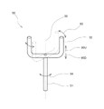
操作部50は、シャフト51と、シャフト51の上端に取付けられたU字形の把持部52とで構成されている。図2に示すように、操作部50は、車両10のインパネ41から車室内に突出するように取り付けられている。操作部50のシャフト51は、図2の矢印91F,91Rに示すように、車両前後方向に傾くように回動すると共に、図3の矢印94に示すように、中心軸59の周りに回動可能となるように車両10のボデーに取付けられている。また、操作部50の把持部52は、図2の矢印92U,92D、図3の矢印95U,95Dに示すように、シャフト51の上端にシャフト51に対して上下方向に移動可能に取付けられている。
The
図1に示すように、シャフト51には、把持部52のシャフト51に対する上下方向位置を検出する位置センサ53と、シャフト51の捩じり角度を検出する捩じり角センサ54と、シャフト51の車両前後方向の傾斜角度を検出する傾斜角センサ55とが取付けられている。図2に示すように、運転席42に座ったドライバ60は、手で操作部50の把持部52をつかんで操作することにより、車両10を駆動、停止、旋回させると共に、車両10の車高を変化させることができる。
As shown in FIG. 1, the
図1に示すように、制御部30は、内部に情報処理を行うプロセッサであるCPU31と、プログラムや制御データを格納するメモリ32とを含むコンピュータで構成されている。制御部30には位置センサ53からの信号と、捩じり角センサ54からの信号と、傾斜角センサ55からの信号とが入力される。また、前輪用モータ15と、後輪用モータ17と、各サスペンションユニット19~22と、各ブレーキユニット23~26と、電動式パワーステアリングユニット27とはそれぞれ制御部30に接続されており、制御部30の指令によって動作する。操作部50と、制御部30とは、車両用操縦装置100を構成する。
As shown in FIG. 1, the
図2の矢印91Fに示すように、ドライバ60が操作部50のシャフト51を車両10の前方向に倒すと、図1に示すシャフト51に取付けられている傾斜角センサ55がシャフト51の車両前後方向の傾斜角度を検出して制御部30に出力する。制御部30は、傾斜角センサ55から入力される信号に基づいて、車両10の前輪用モータ15、後輪用モータ17により車両10を加速或いは発進させたり、減速或いは停止したりする。例えば、制御部30は、傾斜角センサ55からシャフト51が車両前方に向かって傾けられた信号が入力された場合に、車両10の前輪用モータ15、後輪用モータ17の出力を増加させて車両10を加速するようにしてもよい。また、制御部30は、傾斜角センサ55からシャフト51が車両後方に向かって傾けられた信号が入力された場合に、前輪用モータ15、後輪用モータ17の出力を低下させたり、各ブレーキユニット23~26を動作させたりして車両10を減速させたり、停止させたりしてもよい。
When the
また、図2の矢印92U、図3の矢印95Uに示すように、ドライバ60が操作部50の把持部52を上方向に動かすと図1に示すシャフト51に取付けられている位置センサ53が把持部52のシャフト51に対する上下方向位置を検出して制御部30に出力する。制御部30は、位置センサ53から入力される信号に基づいて、4つのサスペンションユニット19~22の高さを変化させて車両10のロール角、或いはピッチ角を変化させる。
2 and
また、図3の矢印93,94に示すように、ドライバ60がシャフト51を中心軸59の周りに捩じるように把持部52を回動させると、図1に示すシャフト51に取付けられている捩じり角センサ54がシャフト51の捩じり角度を検出して制御部30に出力する。制御部30は、捩じり角センサ54から入力される信号に基づいて、電動式パワーステアリングユニット27を動作させて、左右の前輪11,12を操舵して車両10を左右に旋回させる。
When the
このように、ドライバ60は、把持部52によりシャフト51を車両10の前後方向に傾けることで車両10を加速又は減速させ、把持部52によりシャフト51を捩じり方向に回動させることで車両10を左右に旋回させ、把持部52を上下動させることにより、車両10のロール角、或いはピッチ角を変化させることができる。ドライバ60は、3つの操作方向を組み合わせて把持部52を操作することにより、車両10を様々に制御することができる。
Thus, the
例えば、ドライバ60が、把持部52を図3に破線で示すように車両10の上方向から見て反時計回りの方向に操作すると、制御部30は、車両10を左方向に旋回させる。同時に、ドライバ60が把持部52を図3に示す矢印95Uに示すように上方向に移動させると、制御部30は右側の前輪12と後輪14を支持しているサスペンションユニット20,22の空気シリンダに空気を注入してサスペンションユニット20,22の高さを高くし、旋回の外側となる車両10の右側の高さを高くする。これにより、制御部30は、左旋回の際に車両10が左方向に傾斜するように車両10のロール角を制御する。逆に、ドライバ60が把持部52を車両10の上方向から見て時計回りの方向に操作すると同時に上方向に移動させると、制御部30は、車両10を右方向に旋回させると共に、旋回の外側となる車両10の左側のサスペンションユニット19,21の高さを高くして、右旋回の際に車両10が右方向に傾斜するように車両10のロール角を制御する。
For example, when the
また、ドライバ60が把持部52を車両10の上方向から見て反時計周りに操作すると同時に図3の矢印95Dのように下方向に移動させると、制御部30は、車両10を左に旋回させると共に、旋回の内側となる車両10の左側のサスペンションユニット19,21の高さを低くして、左旋回の際に車両10が左方向に傾斜するように車両10のロール角を制御する。また、ドライバ60が把持部52を車両10の上方向から見て時計周りに操作すると同時に下方向に移動させると、制御部30は、車両10を右に旋回させると共に、旋回の内側となる車両10の右側のサスペンションユニット20,22の高さを低くして、右旋回の際に車両10が右方向に傾斜するように車両10のロール角を制御する。
Further, when the
また、ドライバ60が把持部52を図2の矢印91Fに示すように車両10の前方に向かって傾けると同時に図2の矢印92Uに示すように上方向に移動させると、制御部30は、車両10を加速させるとともに、車両10の前輪11,12を支持しているサスペンションユニット19,20の空気シリンダに空気を注入してサスペンションユニット19,20の高さを高くして、車両10の前方が少し持ち上がるように車両10のピッチ角を制御する。逆に、ドライバ60が把持部52を車両10の前方に向かって傾けると同時に図2の矢印92Dに示すように下方向に移動させると、制御部30は、車両10を加速させるとともに、車両10の前輪11,12を支持しているサスペンションユニット19,20の空気シリンダから空気を排出してサスペンションユニット19,20の高さを低くして、車両10の前方が少し沈み込むように車両10のピッチ角を制御する。
Further, when the
更に、ドライバ60が把持部52を図2の矢印91Rに示すように車両10の後方に向かって傾けると同時に図2の矢印92Dに示すように下方向に移動させると、制御部30は、車両10を減速させるとともに、車両10の後輪13,14を支持しているサスペンションユニット21,22の高さを低くして、車両10の前方が沈み込むことを抑制するように車両10のピッチ角を制御する。逆に、ドライバ60が把持部52を車両10の後方に向かって傾けると同時に矢印92Uに示すように上方向に移動させると、制御部30は、車両10を減速させるとともに、車両10の後輪13,14を支持しているサスペンションユニット21,22の高さを高くして、車両10の前方が沈み込むように車両10のピッチ角を制御する。
Further, when the
以上、説明したように、実施形態の車両用操縦装置100は、ドライバ60による把持部52の操作のみにより、車両10を加速、減速、旋回させると共に、車両10のロール角、ピッチ角を自在に変化させることができるので、運転操作の際にドライバ60が車両10との一体感を感じることができる。
As described above, the
なお、以上の説明では、車両10は、空気式のサスペンションユニット19~22を備え、空気シリンダに空気を出し入れすることで高さを変化させることとして説明したが、これに限らず、コイルスプリングとショックアブソーバとで構成されるサスペンション装置に油圧シリンダを組み合わせて高さを調節可能にしたサスペンションユニットを用いてもよい。
In the above description, the
以上説明した実施形態の車両用操縦装置100の操作部50は、把持部52がU字型として説明したが、これに限らず、例えば、図4に示すように、回転式のハンドル72とシャフト71とで構成した操作部70のように構成してもよい。ドライバ60がこの操作部70のハンドル72をシャフト71が車両前後方向に傾くように操作すると、制御部30は、車両10を加速、減速させる。また、ドライバ60がハンドル72を図4に示す矢印98に示すように、上下方向に移動させると制御部30は、各サスペンションユニット19~22を動作させて車両10のロール角、ピッチ角を変化させる。更に、ドライバ60がハンドル72を図4の矢印97に示すように回転させると、制御部30は車両10を左右に旋回させることができる。
In the
図4に示す操作部70を用いて車両用操縦装置100を構成した場合も、操作部50を用いて車両用操縦装置100を構成した場合と同様の効果を奏する。
Even when the
10 車両、11,12 前輪、13,14 後輪、15 前輪用モータ、16 前駆動軸、17 後輪用モータ、18 後駆動軸、19~22 サスペンションユニット、23~26 ブレーキユニット、27 電動式パワーステアリングユニット、28 リンク機構、30 制御部、31 CPU、32 メモリ、41 インパネ、42 運転席、50,70 操作部、51,71 シャフト、52 把持部、53 位置センサ、54 捩じり角センサ、55 傾斜角センサ、59 中心軸、60 ドライバ、72 ハンドル、100 車両用操縦装置。 10 vehicle, 11, 12 front wheels, 13, 14 rear wheels, 15 front wheel motor, 16 front drive shaft, 17 rear wheel motor, 18 rear drive shaft, 19 to 22 suspension unit, 23 to 26 brake unit, 27 electric type Power steering unit, 28 Link mechanism, 30 Control unit, 31 CPU, 32 Memory, 41 Instrument panel, 42 Driver's seat, 50, 70 Operation unit, 51, 71 Shaft, 52 Grip unit, 53 Position sensor, 54 Torsion angle sensor , 55 tilt angle sensor, 59 center shaft, 60 driver, 72 steering wheel, 100 vehicle control device.
Claims (5)
前記操作部の動きに応じて車両を旋回させると共に前記車両の高さを変化させる制御部と、を備える車両用操縦装置であって、
前記制御部は、前記操作部の上下動に応じて前記車両の高さを変化させること、
を特徴とする車両用操縦装置。 an operation unit operated by a driver;
a control unit that turns the vehicle and changes the height of the vehicle according to the movement of the operation unit,
the control unit changing the height of the vehicle according to the vertical movement of the operation unit;
A vehicle control device characterized by:
前記車両は、前後左右の四輪をそれぞれ懸架するサスペンションユニットを備え、
各サスペンションユニットは、それぞれ独立して高さを変更可能であり、
前記制御部は、前記操作部の動きに応じて前記車両の左右のサスペンションユニットの高さ、又は、前記車両の前後のサスペンションユニットの高さを変化させて、前記車両のロール角、或いは、前記車両のピッチ角を変化させること、
を特徴とする車両用操縦装置。 The vehicle operating device according to claim 1,
The vehicle includes a suspension unit that suspends each of the front, rear, left, and right wheels,
Each suspension unit can independently change the height,
The control unit changes the height of the left and right suspension units of the vehicle or the height of the front and rear suspension units of the vehicle in accordance with the movement of the operation unit to change the roll angle of the vehicle or the changing the pitch angle of the vehicle;
A vehicle control device characterized by:
前記操作部は、
車両前後方向に傾くように回動すると共に中心軸の周りに捩じり方向に回動可能なシャフトと、
前記シャフトの上端に上下方向に移動可能に取付けられた把持部と、
前記シャフトの車両前後方向の傾斜角度を検出する傾斜角センサと、
前記シャフトの捩じり角度を検出する捩じり角センサと、
前記把持部の前記シャフトに対する上下方向位置を検出する位置センサと、を含み、
前記制御部は、前記傾斜角センサから入力される信号に応じて前記車両を加速又は減速させ、前記捩じり角センサから入力される信号に応じて前記車両を旋回させ、前記位置センサから入力される信号に応じて前記車両の高さを変化させること、
を特徴とする車両用操縦装置。 The vehicle operating device according to claim 2,
The operation unit is
a shaft that rotates so as to incline in the longitudinal direction of the vehicle and that can rotate in a torsional direction about a central axis;
a gripping part attached to the upper end of the shaft so as to be vertically movable;
a tilt angle sensor that detects the tilt angle of the shaft in the longitudinal direction of the vehicle;
a torsion angle sensor that detects the torsion angle of the shaft;
a position sensor that detects the vertical position of the grip with respect to the shaft;
The control unit accelerates or decelerates the vehicle according to a signal input from the tilt angle sensor, turns the vehicle according to a signal input from the torsion angle sensor, and inputs from the position sensor. varying the height of the vehicle in response to a signal received;
A vehicle control device characterized by:
前記制御部は、前記捩じり角センサからの信号と前記位置センサからの前記把持部が上方向に移動する信号とが同時に入力された場合に、前記車両を左右に旋回させると共に旋回の外側に位置する前後のサスペンションユニットの高さを高くし、
前記捩じり角センサからの信号と前記位置センサからの前記把持部が下方向に移動する信号とが同時に入力された場合に、前記車両を左右に旋回させると共に旋回の内側に位置する前後のサスペンションユニットの高さを低くすること、
を特徴とする車両用操縦装置。 The vehicle operating device according to claim 3,
When the signal from the torsion angle sensor and the signal from the position sensor indicating that the gripping portion moves upward are input at the same time, the control portion causes the vehicle to turn left and right and to the outside of the turn. The height of the front and rear suspension units located in the
When the signal from the torsion angle sensor and the signal from the position sensor indicating that the gripping portion moves downward are input at the same time, the vehicle is turned left and right, and the forward and backward movement positions located on the inside of the turn are turned. lowering the height of the suspension unit,
A vehicle control device characterized by:
前記制御部は、前記傾斜角センサからの信号と前記位置センサからの前記把持部が上方向に移動する信号とが同時に入力された場合に、前記車両を加速又は減速させると共に前記車両の前方又は後方のサスペンションユニットの高さを高くし、
前記傾斜角センサからの信号と前記位置センサからの前記把持部が下方向に移動する信号とが同時に入力された場合に、前記車両を加速又は減速させると共に前記車両の前方又は後方のサスペンションユニットの高さを低くすること、
を特徴とする車両用操縦装置。 The vehicle operating device according to claim 3 or 4,
The control unit accelerates or decelerates the vehicle and moves forward or backward of the vehicle when a signal from the tilt angle sensor and a signal from the position sensor indicating that the gripping unit moves upward are input at the same time. Raise the height of the rear suspension unit,
When the signal from the tilt angle sensor and the signal from the position sensor that the gripping portion moves downward are input at the same time, the vehicle is accelerated or decelerated, and the front or rear suspension unit of the vehicle is adjusted. reduce height,
A vehicle control device characterized by:
Priority Applications (3)
| Application Number | Priority Date | Filing Date | Title |
|---|---|---|---|
| JP2020005606A JP7173060B2 (en) | 2020-01-17 | 2020-01-17 | Vehicle control device |
| US17/145,818 US11518369B2 (en) | 2020-01-17 | 2021-01-11 | Vehicle control device |
| CN202110042357.6A CN113135079B (en) | 2020-01-17 | 2021-01-13 | Vehicle control device |
Applications Claiming Priority (1)
| Application Number | Priority Date | Filing Date | Title |
|---|---|---|---|
| JP2020005606A JP7173060B2 (en) | 2020-01-17 | 2020-01-17 | Vehicle control device |
Publications (2)
| Publication Number | Publication Date |
|---|---|
| JP2021112946A JP2021112946A (en) | 2021-08-05 |
| JP7173060B2 true JP7173060B2 (en) | 2022-11-16 |
Family
ID=76810081
Family Applications (1)
| Application Number | Title | Priority Date | Filing Date |
|---|---|---|---|
| JP2020005606A Active JP7173060B2 (en) | 2020-01-17 | 2020-01-17 | Vehicle control device |
Country Status (3)
| Country | Link |
|---|---|
| US (1) | US11518369B2 (en) |
| JP (1) | JP7173060B2 (en) |
| CN (1) | CN113135079B (en) |
Citations (4)
| Publication number | Priority date | Publication date | Assignee | Title |
|---|---|---|---|---|
| JP3118202B2 (en) | 1997-02-12 | 2000-12-18 | マツダ株式会社 | Repair method for spline wear |
| JP3143785B2 (en) | 1997-03-28 | 2001-03-07 | 株式会社ホンダロック | Steering lock device |
| JP2002240590A (en) | 2001-02-20 | 2002-08-28 | Toyota Motor Corp | Vehicle driving operation device |
| JP2009262915A (en) | 2008-04-01 | 2009-11-12 | Denso Corp | Vehicle driving actuator and vehicle |
Family Cites Families (20)
| Publication number | Priority date | Publication date | Assignee | Title |
|---|---|---|---|---|
| JPH03118202A (en) * | 1989-09-29 | 1991-05-20 | Mazda Motor Corp | Suspension device for vehicle |
| JP2827340B2 (en) * | 1989-10-27 | 1998-11-25 | 井関農機株式会社 | Work vehicle |
| SE9003318L (en) * | 1990-10-19 | 1991-11-11 | Saab Automobile | REGULATION, ARRANGEMENTS AND PROCEDURES FOR REGULATION OF SERVICE ORGANIZATIONS BEFORE MOTOR VEHICLES |
| JP3014823B2 (en) * | 1991-09-19 | 2000-02-28 | マツダ株式会社 | Vehicle integrated control device |
| GB9213268D0 (en) * | 1992-06-23 | 1992-08-05 | Rover Group | A suspension system for a vehicle |
| TW522103B (en) * | 1997-11-14 | 2003-03-01 | Toyoda Automatic Loom Works | Axle tilt control apparatus for industrial vehicles |
| US6671596B2 (en) * | 2000-12-27 | 2003-12-30 | Honda Giken Kogyo Kabushiki Kaisha | Control method for suspension |
| JP4292907B2 (en) * | 2003-07-17 | 2009-07-08 | 株式会社アドヴィックス | Vehicle motion control device |
| JP2006347351A (en) * | 2005-06-15 | 2006-12-28 | Denso Corp | Vehicle control system |
| JP2007045225A (en) | 2005-08-08 | 2007-02-22 | Toyota Motor Corp | Vehicle height adjustment device |
| US20070241522A1 (en) * | 2006-04-13 | 2007-10-18 | Tsang-Chao Tsai | Active automobile turn gravity change control apparatus |
| DE102011078262B4 (en) * | 2011-06-29 | 2020-12-10 | Ford Global Technologies, Llc | Independent wheel suspension with automatic camber adjustment |
| JPWO2014102884A1 (en) * | 2012-12-28 | 2017-01-12 | トヨタ自動車株式会社 | Vehicle control device |
| US10487761B2 (en) * | 2013-05-31 | 2019-11-26 | Hitachi Automotive Systems, Ltd. | Vehicle control apparatus and vehicle control method |
| CN104709026B (en) * | 2014-12-31 | 2017-10-03 | 盐城工学院 | The control system and its control method of automobile turning anti-rollover |
| CN105437903B (en) * | 2015-11-26 | 2018-09-18 | 三一汽车起重机械有限公司 | A kind of preventing vehicle rollover control system and crane |
| JP6458769B2 (en) * | 2016-05-18 | 2019-01-30 | トヨタ自動車株式会社 | Hybrid car |
| JP2017207885A (en) * | 2016-05-18 | 2017-11-24 | 本田技研工業株式会社 | Vehicle control system, vehicle control method, and vehicle control program |
| JP6423392B2 (en) * | 2016-07-28 | 2018-11-14 | トヨタ自動車株式会社 | Control device for automatic transmission |
| US11383832B2 (en) * | 2017-12-12 | 2022-07-12 | Cameron Spencer | Variable-geometry vertical take-off and landing (VTOL) aircraft system |
-
2020
- 2020-01-17 JP JP2020005606A patent/JP7173060B2/en active Active
-
2021
- 2021-01-11 US US17/145,818 patent/US11518369B2/en active Active
- 2021-01-13 CN CN202110042357.6A patent/CN113135079B/en active Active
Patent Citations (4)
| Publication number | Priority date | Publication date | Assignee | Title |
|---|---|---|---|---|
| JP3118202B2 (en) | 1997-02-12 | 2000-12-18 | マツダ株式会社 | Repair method for spline wear |
| JP3143785B2 (en) | 1997-03-28 | 2001-03-07 | 株式会社ホンダロック | Steering lock device |
| JP2002240590A (en) | 2001-02-20 | 2002-08-28 | Toyota Motor Corp | Vehicle driving operation device |
| JP2009262915A (en) | 2008-04-01 | 2009-11-12 | Denso Corp | Vehicle driving actuator and vehicle |
Also Published As
| Publication number | Publication date |
|---|---|
| US11518369B2 (en) | 2022-12-06 |
| US20210221356A1 (en) | 2021-07-22 |
| CN113135079A (en) | 2021-07-20 |
| JP2021112946A (en) | 2021-08-05 |
| CN113135079B (en) | 2023-09-19 |
Similar Documents
| Publication | Publication Date | Title |
|---|---|---|
| JP6097694B2 (en) | Electric vehicle | |
| EP1950171A2 (en) | Travel control apparatus for industrial vehicle | |
| JP4310462B2 (en) | vehicle | |
| JP4482442B2 (en) | vehicle | |
| JP4894589B2 (en) | vehicle | |
| JP2007118807A (en) | Vehicle | |
| JP7173060B2 (en) | Vehicle control device | |
| JP6559111B2 (en) | Riding work machine | |
| WO2020138395A1 (en) | Inclining vehicle equipped with steerable front wheel | |
| JP2007153024A (en) | Vehicle | |
| JP5007473B2 (en) | Motorcycle headlight optical axis adjustment device | |
| JP4647916B2 (en) | Motorcycle with auxiliary wheels | |
| JP4780178B2 (en) | vehicle | |
| JP2010030523A (en) | Two-wheeled vehicle | |
| JP4508795B2 (en) | Vehicle travel control device | |
| JP6722916B2 (en) | vehicle | |
| JP2009073350A (en) | Control device | |
| JP2006160406A (en) | Cargo-handling vehicle | |
| JP5873938B1 (en) | Omni-directional forklift | |
| WO2019059346A1 (en) | Motorcycle | |
| JP2016049787A (en) | Inverted moving body | |
| JP2001180899A (en) | Safety device vehicle for high lift work | |
| JP7111083B2 (en) | two-wheeled vehicle | |
| JP2018134969A (en) | Vehicle equipped with lean mechanism | |
| JP4798382B2 (en) | Traveling vehicle |
Legal Events
| Date | Code | Title | Description |
|---|---|---|---|
| A621 | Written request for application examination |
Free format text: JAPANESE INTERMEDIATE CODE: A621 Effective date: 20220214 |
|
| A977 | Report on retrieval |
Free format text: JAPANESE INTERMEDIATE CODE: A971007 Effective date: 20220921 |
|
| TRDD | Decision of grant or rejection written | ||
| A01 | Written decision to grant a patent or to grant a registration (utility model) |
Free format text: JAPANESE INTERMEDIATE CODE: A01 Effective date: 20221004 |
|
| A61 | First payment of annual fees (during grant procedure) |
Free format text: JAPANESE INTERMEDIATE CODE: A61 Effective date: 20221017 |
|
| R151 | Written notification of patent or utility model registration |
Ref document number: 7173060 Country of ref document: JP Free format text: JAPANESE INTERMEDIATE CODE: R151 |