JP7143521B2 - Guide system for guiding movably supported doors - Google Patents
Guide system for guiding movably supported doors Download PDFInfo
- Publication number
- JP7143521B2 JP7143521B2 JP2021526369A JP2021526369A JP7143521B2 JP 7143521 B2 JP7143521 B2 JP 7143521B2 JP 2021526369 A JP2021526369 A JP 2021526369A JP 2021526369 A JP2021526369 A JP 2021526369A JP 7143521 B2 JP7143521 B2 JP 7143521B2
- Authority
- JP
- Japan
- Prior art keywords
- support
- guide rail
- guide
- locking
- guide system
- Prior art date
- Legal status (The legal status is an assumption and is not a legal conclusion. Google has not performed a legal analysis and makes no representation as to the accuracy of the status listed.)
- Active
Links
- 230000007704 transition Effects 0.000 description 3
- 239000000463 material Substances 0.000 description 2
- 238000005096 rolling process Methods 0.000 description 2
- 230000001419 dependent effect Effects 0.000 description 1
Images


Classifications
-
- E—FIXED CONSTRUCTIONS
- E05—LOCKS; KEYS; WINDOW OR DOOR FITTINGS; SAFES
- E05D—HINGES OR SUSPENSION DEVICES FOR DOORS, WINDOWS OR WINGS
- E05D15/00—Suspension arrangements for wings
- E05D15/56—Suspension arrangements for wings with successive different movements
- E05D15/58—Suspension arrangements for wings with successive different movements with both swinging and sliding movements
-
- E—FIXED CONSTRUCTIONS
- E05—LOCKS; KEYS; WINDOW OR DOOR FITTINGS; SAFES
- E05D—HINGES OR SUSPENSION DEVICES FOR DOORS, WINDOWS OR WINGS
- E05D15/00—Suspension arrangements for wings
- E05D15/26—Suspension arrangements for wings for folding wings
- E05D15/264—Suspension arrangements for wings for folding wings for bi-fold wings
-
- E—FIXED CONSTRUCTIONS
- E06—DOORS, WINDOWS, SHUTTERS, OR ROLLER BLINDS IN GENERAL; LADDERS
- E06B—FIXED OR MOVABLE CLOSURES FOR OPENINGS IN BUILDINGS, VEHICLES, FENCES OR LIKE ENCLOSURES IN GENERAL, e.g. DOORS, WINDOWS, BLINDS, GATES
- E06B3/00—Window sashes, door leaves, or like elements for closing wall or like openings; Layout of fixed or moving closures, e.g. windows in wall or like openings; Features of rigidly-mounted outer frames relating to the mounting of wing frames
- E06B3/32—Arrangements of wings characterised by the manner of movement; Arrangements of movable wings in openings; Features of wings or frames relating solely to the manner of movement of the wing
- E06B3/48—Wings connected at their edges, e.g. foldable wings
- E06B3/481—Wings foldable in a zig-zag manner or bi-fold wings
- E06B3/482—Wings foldable in a zig-zag manner or bi-fold wings specially adapted for furniture
-
- E—FIXED CONSTRUCTIONS
- E06—DOORS, WINDOWS, SHUTTERS, OR ROLLER BLINDS IN GENERAL; LADDERS
- E06B—FIXED OR MOVABLE CLOSURES FOR OPENINGS IN BUILDINGS, VEHICLES, FENCES OR LIKE ENCLOSURES IN GENERAL, e.g. DOORS, WINDOWS, BLINDS, GATES
- E06B3/00—Window sashes, door leaves, or like elements for closing wall or like openings; Layout of fixed or moving closures, e.g. windows in wall or like openings; Features of rigidly-mounted outer frames relating to the mounting of wing frames
- E06B3/32—Arrangements of wings characterised by the manner of movement; Arrangements of movable wings in openings; Features of wings or frames relating solely to the manner of movement of the wing
- E06B3/50—Arrangements of wings characterised by the manner of movement; Arrangements of movable wings in openings; Features of wings or frames relating solely to the manner of movement of the wing with more than one kind of movement
- E06B3/5045—Arrangements of wings characterised by the manner of movement; Arrangements of movable wings in openings; Features of wings or frames relating solely to the manner of movement of the wing with more than one kind of movement specially adapted for furniture
-
- E—FIXED CONSTRUCTIONS
- E05—LOCKS; KEYS; WINDOW OR DOOR FITTINGS; SAFES
- E05D—HINGES OR SUSPENSION DEVICES FOR DOORS, WINDOWS OR WINGS
- E05D15/00—Suspension arrangements for wings
- E05D15/56—Suspension arrangements for wings with successive different movements
- E05D15/58—Suspension arrangements for wings with successive different movements with both swinging and sliding movements
- E05D2015/586—Suspension arrangements for wings with successive different movements with both swinging and sliding movements with travelling hinge parts
-
- E—FIXED CONSTRUCTIONS
- E05—LOCKS; KEYS; WINDOW OR DOOR FITTINGS; SAFES
- E05Y—INDEXING SCHEME ASSOCIATED WITH SUBCLASSES E05D AND E05F, RELATING TO CONSTRUCTION ELEMENTS, ELECTRIC CONTROL, POWER SUPPLY, POWER SIGNAL OR TRANSMISSION, USER INTERFACES, MOUNTING OR COUPLING, DETAILS, ACCESSORIES, AUXILIARY OPERATIONS NOT OTHERWISE PROVIDED FOR, APPLICATION THEREOF
- E05Y2201/00—Constructional elements; Accessories therefor
- E05Y2201/20—Brakes; Disengaging means; Holders; Stops; Valves; Accessories therefor
- E05Y2201/218—Holders
- E05Y2201/22—Locks
-
- E—FIXED CONSTRUCTIONS
- E05—LOCKS; KEYS; WINDOW OR DOOR FITTINGS; SAFES
- E05Y—INDEXING SCHEME ASSOCIATED WITH SUBCLASSES E05D AND E05F, RELATING TO CONSTRUCTION ELEMENTS, ELECTRIC CONTROL, POWER SUPPLY, POWER SIGNAL OR TRANSMISSION, USER INTERFACES, MOUNTING OR COUPLING, DETAILS, ACCESSORIES, AUXILIARY OPERATIONS NOT OTHERWISE PROVIDED FOR, APPLICATION THEREOF
- E05Y2201/00—Constructional elements; Accessories therefor
- E05Y2201/60—Suspension or transmission members; Accessories therefor
- E05Y2201/622—Suspension or transmission members elements
- E05Y2201/638—Cams; Ramps
-
- E—FIXED CONSTRUCTIONS
- E05—LOCKS; KEYS; WINDOW OR DOOR FITTINGS; SAFES
- E05Y—INDEXING SCHEME ASSOCIATED WITH SUBCLASSES E05D AND E05F, RELATING TO CONSTRUCTION ELEMENTS, ELECTRIC CONTROL, POWER SUPPLY, POWER SIGNAL OR TRANSMISSION, USER INTERFACES, MOUNTING OR COUPLING, DETAILS, ACCESSORIES, AUXILIARY OPERATIONS NOT OTHERWISE PROVIDED FOR, APPLICATION THEREOF
- E05Y2201/00—Constructional elements; Accessories therefor
- E05Y2201/60—Suspension or transmission members; Accessories therefor
- E05Y2201/622—Suspension or transmission members elements
- E05Y2201/684—Rails; Tracks
-
- E—FIXED CONSTRUCTIONS
- E05—LOCKS; KEYS; WINDOW OR DOOR FITTINGS; SAFES
- E05Y—INDEXING SCHEME ASSOCIATED WITH SUBCLASSES E05D AND E05F, RELATING TO CONSTRUCTION ELEMENTS, ELECTRIC CONTROL, POWER SUPPLY, POWER SIGNAL OR TRANSMISSION, USER INTERFACES, MOUNTING OR COUPLING, DETAILS, ACCESSORIES, AUXILIARY OPERATIONS NOT OTHERWISE PROVIDED FOR, APPLICATION THEREOF
- E05Y2201/00—Constructional elements; Accessories therefor
- E05Y2201/60—Suspension or transmission members; Accessories therefor
- E05Y2201/622—Suspension or transmission members elements
- E05Y2201/688—Rollers
-
- E—FIXED CONSTRUCTIONS
- E05—LOCKS; KEYS; WINDOW OR DOOR FITTINGS; SAFES
- E05Y—INDEXING SCHEME ASSOCIATED WITH SUBCLASSES E05D AND E05F, RELATING TO CONSTRUCTION ELEMENTS, ELECTRIC CONTROL, POWER SUPPLY, POWER SIGNAL OR TRANSMISSION, USER INTERFACES, MOUNTING OR COUPLING, DETAILS, ACCESSORIES, AUXILIARY OPERATIONS NOT OTHERWISE PROVIDED FOR, APPLICATION THEREOF
- E05Y2900/00—Application of doors, windows, wings or fittings thereof
- E05Y2900/20—Application of doors, windows, wings or fittings thereof for furniture, e.g. cabinets
- E05Y2900/208—Application of doors, windows, wings or fittings thereof for furniture, e.g. cabinets for metal cabinets
-
- E—FIXED CONSTRUCTIONS
- E05—LOCKS; KEYS; WINDOW OR DOOR FITTINGS; SAFES
- E05Y—INDEXING SCHEME ASSOCIATED WITH SUBCLASSES E05D AND E05F, RELATING TO CONSTRUCTION ELEMENTS, ELECTRIC CONTROL, POWER SUPPLY, POWER SIGNAL OR TRANSMISSION, USER INTERFACES, MOUNTING OR COUPLING, DETAILS, ACCESSORIES, AUXILIARY OPERATIONS NOT OTHERWISE PROVIDED FOR, APPLICATION THEREOF
- E05Y2900/00—Application of doors, windows, wings or fittings thereof
- E05Y2900/20—Application of doors, windows, wings or fittings thereof for furniture, e.g. cabinets
- E05Y2900/212—Doors disappearing in pockets in the furniture body
Landscapes
- Engineering & Computer Science (AREA)
- Mechanical Engineering (AREA)
- Civil Engineering (AREA)
- Structural Engineering (AREA)
- Support Devices For Sliding Doors (AREA)
- Drawers Of Furniture (AREA)
- Bearings For Parts Moving Linearly (AREA)
- Power-Operated Mechanisms For Wings (AREA)
- Extensible Doors And Revolving Doors (AREA)
- Warehouses Or Storage Devices (AREA)
Description
本発明は、可動に支持された少なくとも1つの扉を案内するためのガイドシステムであって、
-少なくとも1つの扉を案内するための、所定の長手方向を有する少なくとも1つのガイドレールと、
-少なくとも1つの扉に結合可能であって、少なくとも1つのガイドレールに沿って走行可能に支持されている少なくとも1つの走行キャリッジと、
-少なくとも1つの走行キャリッジを配置することができる支持体であって、支持体は、少なくとも1つのガイドレールの長手方向に対して横方向に延在する方向に可動に支持されており、支持体は、組付け位置で移送位置へと移動可能であって、移送位置で支持体は少なくとも1つのガイドレールに前述の長手方向で接続していて、これにより走行キャリッジは、少なくとも1つのガイドレールと支持体との間で往復移送可能である、支持体と、
-前述の長手方向に対して横方向に延在する方向での支持体の移動を阻止するまたはロックするように、支持体を移送位置において解除可能にロックするロック装置であって、少なくとも1つのガイドレールと支持体との間を解除可能にロックするための、可動に支持された少なくとも1つのロックエレメントを有しているロック装置と、
-少なくとも部分的に湾曲して形成されている少なくとも1つの制御輪郭であって、これにより走行キャリッジは、少なくとも1つのガイドレールから支持体への移送の際に、前述の長手方向に対して横方向に延在する方向で少なくとも部分的に移動可能となる、制御輪郭と、
を含むガイドシステムに関する。
The present invention is a guide system for guiding at least one movably supported door, comprising:
- at least one guide rail with a predetermined longitudinal direction for guiding at least one door;
- at least one traveling carriage connectable to at least one door and supported for travel along at least one guide rail;
a support on which at least one traveling carriage can be arranged, the support being movably supported in a direction extending transversely to the longitudinal direction of the at least one guide rail; is movable in the assembly position into a transfer position, in which the support is longitudinally connected to the at least one guide rail, whereby the traveling carriage is connected to the at least one guide rail. a support reciprocally transferable to and from the support;
- a locking device for releasably locking the support in the transfer position so as to prevent or lock movement of the support in a direction extending transversely to said longitudinal direction, comprising at least one a locking device comprising at least one movably supported locking element for releasable locking between the guide rail and the support;
- at least one control contour, which is at least partially curved, by means of which the traveling carriage is transversely to said longitudinal direction during transfer from the at least one guide rail to the support; a control contour that is at least partially movable in a direction extending in a direction;
relating to a guide system comprising:
本発明はさらに、上述した形式のガイドシステムを備えた家具に関する。 The invention further relates to furniture with a guide system of the type described above.
優先権が先行しているが、公開が後であったオーストリア国特許発明第519902号明細書には、扉を動かすためのガイドシステムが示されており、このガイドシステムは、第1のガイドレールと、第1のガイドレールに対して横方向に延在する第2のガイドレールとを有している。ガイドキャリッジによって、扉は、第1のガイドレールに沿って走行可能であり、ガイドキャリッジは、横方向に延在する第2のガイドレールに沿った運動のために支持体上へと移送可能である。この支持体は、移送位置で、第1のガイドレールの長手方向で続いていて、移送位置で第1のガイドレールに解除可能にロックされている。ガイドキャリッジが支持体上へと進入することにより、第1のガイドレールと支持体との間のロックは解除可能であり、これにより支持体は、横方向に延在する第2のガイドレールに沿った移動のために解放される。移送位置では、支持体は、可動に支持されたロックレバーによって、第1のガイドレールにロックされており、ガイドキャリッジは、支持体への進入の際に、ロックレバーを解除位置へと動かし、これにより支持体は第1のガイドレールからロック解除可能となる。ガイドキャリッジは、少なくとも1つの走行ローラを有していて、この走行ローラはアダプタ部材の円弧状の制御輪郭に沿って走行可能である。このようにして、ガイドキャリッジに接続された扉は、第2のガイドレールの方向に変向されるので、第1のガイドレールと第2のガイドレールとの間の移行領域における扉の移動は改善される。しかしながら、ガイドキャリッジによるロックレバーの操作と、円弧状の制御輪郭に沿ったガイドキャリッジの走行ローラの運動とが互いに正確には合わせられない場合に、問題が生じるおそれがある。これにより例えば、ガイドキャリッジによるロックレバーのロック位置からの解除が早過ぎるまたは遅すぎる場合があり、ガイドキャリッジの走行ローラが、円弧状の制御輪郭にひっかかって動かなくなる恐れがある。 Austrian Patent Specification No. 519902, which preceded priority but was published later, shows a guide system for moving a door, which guide system comprises a first guide rail and a second guide rail extending transversely to the first guide rail. By means of the guide carriage the door can be driven along a first guide rail and the guide carriage can be transported onto the support for movement along a second laterally extending guide rail. be. In the transfer position, this support follows the first guide rail in the longitudinal direction and is releasably locked to the first guide rail in the transfer position. By advancing the guide carriage onto the support, the lock between the first guide rail and the support can be released so that the support moves into the laterally extending second guide rail. freed for movement along. In the transfer position the support is locked to the first guide rail by a movably supported locking lever, the guide carriage moving the locking lever into the unlocked position on entry into the support, This allows the support to be unlocked from the first guide rail. The guide carriage has at least one running roller, which can run along the arcuate control contour of the adapter member. In this way the door connected to the guide carriage is deflected in the direction of the second guide rail so that the movement of the door in the transition area between the first and second guide rail is be improved. However, problems can arise if the actuation of the locking lever by the guide carriage and the movement of the running roller of the guide carriage along the arc-shaped control contour are not precisely coordinated with each other. As a result, for example, the guide carriage may release the locking lever from the locking position too early or too late, and the running rollers of the guide carriage may jam against the arcuate control contour.
本発明の課題は、上述した欠点を回避する冒頭で述べた形式のガイドシステムを提供することである。 SUMMARY OF THE INVENTION It is an object of the present invention to provide a guide system of the type mentioned at the outset which avoids the disadvantages mentioned above.
この課題は、本発明によれば、請求項1の特徴により解決される。本発明のさらに好適な実施例は、従属請求項に記載されている。
This task is solved according to the invention by the features of
本発明によれば、可動に支持された少なくとも1つのロックエレメントが、少なくとも1つの制御輪郭に沿って走行可能な少なくとも1つの支持エレメントを有していることが特定されている。 According to the invention, it is specified that the at least one movably supported locking element has at least one support element that can be moved along at least one control contour.
換言すると、ロックエレメントは2つの機能を有している。なぜならば、ロックエレメントは一方では、支持体と第1のガイドレールとの間の解除可能なロックのために形成されているからであり、他方では、ロックエレメントは、第1のガイドレールと第2のガイドレールとの間の移行領域で円弧状の制御輪郭に沿って走行可能な少なくとも1つの支持エレメント(例えば滑動部材または転動体)を有しているからである。このようにして、第1のガイドレールに関する支持体のロックおよびロック解除と、制御輪郭に沿った支持エレメントの移動とは時間的に改善されて互いに合わせられており、支持エレメントが円弧状の制御輪郭に引っかかって動かなくなる危険は阻止される。 In other words, the locking element has two functions. This is because, on the one hand, the locking element is designed for releasable locking between the support and the first guide rail, and on the other hand, the locking element is designed for the first guide rail and the first guide rail. This is because it has at least one support element (for example a sliding member or rolling element) which can run along a circular control contour in the transition area between the two guide rails. In this way, the locking and unlocking of the support with respect to the first guide rail and the movement of the support element along the control contour are timely coordinated with each other so that the support element has an arcuate control profile. The danger of getting stuck in the contour is prevented.
少なくとも1つのロックエレメントは、例えば支持体に可動に支持されていてよい。代替的に、ロックエレメントが第1のガイドレールにまたは第1のガイドレールに接続されるアダプタ部材に配置されていてもよい。 At least one locking element may be movably supported, for example, on a support. Alternatively, the locking element may be arranged on the first guide rail or on an adapter member connected to the first guide rail.
1つの実施例によれば、少なくとも1つのロックエレメントは、直線的に摺動可能に支持されていてよい。このようにして、ロックエレメントを省スペースに配置することができ、ロックエレメントのラインから外れた動きを阻止することができる。少なくとも1つのロックエレメントの直線状の摺動運動の方向は、この場合、第1のガイドレールの長手方向に対して実質的に平行に延在することができるので、ロックエレメントは、走行キャリッジの並進運動により直接制御可能である。 According to one embodiment, the at least one locking element may be linearly slidably supported. In this way, the locking element can be arranged in a space-saving manner and an out-of-line movement of the locking element can be prevented. The direction of linear sliding movement of the at least one locking element can in this case extend substantially parallel to the longitudinal direction of the first guide rail, so that the locking element can Directly controllable by translational motion.
別の実施例によれば、少なくとも1つの蓄力器が設けられていてよく、ロックエレメントの支持エレメントは、蓄力器の力によって、少なくとも部分的に制御輪郭に対して押し付け可能である。蓄力器の力によって支持エレメントが制御輪郭に当て付けられることにより、支持体と第1のガイドレールとの間のロック解除、第1のガイドレールと第2のガイドレールとの間の移行領域におけるロックエレメントの動きの経過、ならびに支持体と第1のガイドレールとの間のロックを、正確に、時間的遅延なく、制御することができる。 According to another embodiment, at least one force store can be provided, the supporting element of the locking element being pressable at least partially against the control contour by the force of the force store. Unlocking between the support and the first guide rail, transition area between the first guide rail and the second guide rail, due to the application of the force of the force store to the support element against the control profile , as well as the locking between the support and the first guide rail can be controlled precisely and without time delay.
制御輪郭に対して支持エレメントを負荷するための蓄力器は、少なくともコイルばねを有していてよい。代替的に、蓄力器は、プラスチック部分の材料弾性により形成されてもよい。 The force store for loading the support element against the control profile can have at least a helical spring. Alternatively, the energy store can be formed by the material elasticity of the plastic part.
ロックエレメントの少なくとも1つの支持エレメントは、好適な実施形態によれば、回転対称的に、好適には走行ローラとして形成されていてよい。 According to a preferred embodiment, at least one support element of the locking element can be designed rotationally symmetrically, preferably as a running roller.
本発明のその他の詳細および利点は、以下の図面の説明により明らかである。 Further details and advantages of the invention are evident from the following description of the drawings.
図1aは、家具本体2と、可動の扉3a,3b,4a,4bを有する折戸とを有した家具1の斜視図を示す。扉3a,3bおよび扉4a,4bは、ガイドシステム5によって、扉3a,3b;4a,4bが互いに実質的に同一平面を成すように整列させられた第1の位置と、扉3a,3b;4a,4bが互いに実質的に平行に整列させられた第2の位置との間で可動に支持されている。扉3a,3bが、第2の(平行に整列させられた)位置で、家具本体2の側方の収容ポケット8a内に押込み可能となるのに対して、扉4a,4bは、互いに平行な位置で別の収容ポケット8b内に押込み可能となる。機能形式は、以下に扉3aおよび3bにつき説明するが、扉4a,4bについても同じ説明があてはまる。ガイドシステム5は、長手方向(L)に延在する第1のガイドレール7を含み、第2の扉3bに連結可能な走行キャリッジ6が、この第1のガイドレール7に沿って走行可能に支持されている。第1のガイドレール7は、組付け位置においては、実質的に水平かつ家具本体2の前縁に対して平行に配置されている。
FIG. 1a shows a perspective view of a piece of
図1bは家具1を示し、扉3a,3bは、図1aに示した同一平面の位置から出て、互いに所定の角度を成す位置へと移動している。第1の扉3aは例えば、2つ以上の家具ヒンジ10を介して支持体11に可動に支持されていてよく、支持体11は方向(Z)で収容ポケット8a内に押込み可能である。図中、支持体11は、移送位置にあり、したがって走行キャリッジ6は、第1のガイドレール7と支持体11との間で往復移動可能である。図示した移送位置では、支持体11が、第1のガイドレール7に対して解除可能にロックされており、支持体11のロックは、支持体11内または支持体11上への走行キャリッジ6の進入によって解除可能となる。支持体11は、扉3a,3bの高さの少なくとも半分の高さに相当する長さを有する細長いピラーの形態で形成されている。両扉3a,3bは、少なくとも1つのヒンジ金具9を介して、組付け位置で鉛直方向に延在する軸線を中心として互いに枢動自在に結合されている。第2の扉3bは、走行キャリッジ6を介して第1のガイドレール7に沿って走行可能に案内されている。
FIG. 1b shows the
図2aは、現状で互いに平行に整列させられている扉3a,3bを備えた家具1を示す。支持体11は、走行キャリッジ6の進入により、第1のガイドレール7からロック解除されたので、支持体11は(走行キャリッジ6と扉3a,3bと共に)、方向(Z)において、ガイドシステム5の、第1のガイドレール7の長手方向(L)に対して横方向に延在する第2のガイドレール17(図3)に沿って収容ポケット8a内へと押込み可能となる。
Figure 2a shows a piece of
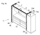
図2bは、現状で収容ポケット8a内に完全に押し込まれた状態にある扉3a,3bを備えた家具1を示す。すなわち扉3a,3bは、ガイドシステム5によって、扉3a,3bが互いに実質的に同一平面を成すように整列させられた図1aに示した第1の位置と、扉3a,3bが互いに実質的に平行に整列させられていて、収容ポケット8aの内部に収容可能となる図2bに示した第2の位置とを起点として可動に支持されている。こうして、例えば、図2aおよび図2bに示したキッチン12を完全に遮蔽することができ、これによって、キッチン12を、外側の居住空間の領域から視覚的に分離することができる。収容ポケット8aは、図示の実施例では、側壁13aと、この側壁13aから平行に離間された固定の家具部分13bとによって形成されており、扉3a,3bは、互いに平行な位置(状態)で、側壁13aと固定の家具部分13bとの間に押込み可能となる。
Figure 2b shows the
図3は、扉3a,3bを収容するための収容ポケット8aを形成する側壁13aと固定の家具部分13bとの間の領域におけるガイドシステム5の斜視図を示す。第1のガイドレール7は、組付け位置で家具本体2の前縁に対して平行な長手方向(L)に延在している。固定の家具部分13bには、長手方向(L2)に延在する第2のガイドレール17が配置されており、第1のガイドレール7の長手方向(L)と第2のガイドレール17の長手方向(L2)とは、互いに交差して、好適には実質的に直交している。支持体11は、少なくとも1つの扉3aを可動に支持するために構成されており、扉3aは組付け状態において、例えば2つ以上の家具ヒンジ10(図1b)を介して支持体11に、組付け位置で鉛直方向に延在する軸線を中心として旋回可能に支持されている。支持体11は、少なくとも1つのガイド装置14を有しており、このガイド装置によって支持体11は、第2のガイドレール17に沿って方向(Z)に、かつ方向(Z)とは逆方向に可動である。図中、支持体11のガイド装置14は、第2のガイドレール17の第1の走行路17aに沿って可動に支持された少なくとも1つの走行ローラ14aを有している。
FIG. 3 shows a perspective view of the
図示の実施例では、支持体11は、受入れ装置15を介して第1のガイドレール7に解除可能にロック可能である。受入れ装置15は、走行キャリッジ6を受け入れるように構成されており、これによって、走行キャリッジ6が、第1のガイドレール7から出発して受入れ装置15内に走入可能となる。この目的のために、第1のガイドレール7に複数のガイド溝20,21を形成することができる。これらのガイド溝は、第1のガイドレール7の長手方向(L)に延びていて、受入れ装置15の移送位置において、この受入れ装置15に設けられた対応するガイド溝20a,21aとそれぞれ一列に整列している。こうして、走行キャリッジ6の走行ローラ30,30a(図8)が、不都合な衝突縁部に衝突することなく、第1のガイドレール7と受入れ装置15との間で走行可能となる。
In the illustrated embodiment, the
受入れ装置15と支持体11との間の切離しを改善するために、受入れ装置15が、支持体11のガイド装置14とは別個の少なくとも1つの支持ローラ16を有していることが特定されていてよい。この支持ローラ16は、第2のガイドレール17に沿って可動に支持されている。好ましくは、この第2のガイドレール17が、第1の走行路17aと、この第1の走行路17aとは別個の少なくとも1つの第2の走行路17bとを有していることが特定されている。ガイド装置14の走行ローラ14aは、第2のガイドレール17の第1の走行路17aに沿って可動に支持されており、受入れ装置15の少なくとも1つの支持ローラ16は、第2のガイドレール17の第2の走行路17bに沿って可動に支持されている。
To improve the decoupling between the receiving
支持体11と受入れ装置15とは、方向(Z)への第2のガイドレール17に沿った運動の際に連動するように互いに結合されている。好ましくは、支持体11と受入れ装置15は、方向(Z)および方向(Z)とは逆方向での第2のガイドレール17に沿った運動の際に遊びなしに互いに連結されている。支持体11の支持を改善するために、別のガイドレール18が設けられていてよく、このガイドレールに沿って、支持体11の少なくとも1つの別の走行ローラ19が走行可能に支持されている。
The
支持体11は、図3に示した移送位置では、ロック装置31によって解除可能にロックされているので、支持体11の移動は、長手方向(L)に対して横方向に延在する方向(Z)で阻止またはロックされている。ロック装置31は、少なくとも1つのロックエレメント32を含み、このロックエレメント32は例えば支持体11に沿って長手方向(L)に直線的に摺動可能に支持されている。少なくとも区分的に湾曲して形成されている制御輪郭22が示されており、この制御輪郭22によって、走行キャリッジ6は、第1のガイドレール7から支持体11へと移送されると、長手方向(L)に対して横方向に延在する方向(Z)に少なくとも所定の区分移動可能である。円弧状の制御輪郭22は、図示した実施例では、アダプタ部材23に配置または形成されており、アダプタ部材23は、第1のガイドレール7の端部領域に配置されている。ロックエレメント32には、(この図では見えない)支持エレメント25(図4)が、回転軸24を中心として回転可能に支持されており、支持エレメント25は、支持体11が第1のガイドレール7からロック解除された後、制御輪郭22に沿って走行可能となる。方向(Z)での支持体11の運動を可能にするために、支持体11のロックは、支持体11内または支持体11上への走行キャリッジ6の進入により解除可能となっている。このために走行キャリッジ6は、ロックエレメント32の対応ストッパ27と協働するストッパ26を有していて、これによりロックエレメント32は、蓄力器28(図8)の力に抗して、支持体11の直線ガイド29に沿って、第1のガイドレール7から離される。
3, the
図4は、ガイドシステム5を平面図で示しており、第1のガイドレール7と、第1のガイドレール7に対して直交方向に延在する第2のガイドレール17とが示されている。第1のガイドレール7の端部領域には、円弧状の制御輪郭22が配設されているアダプタ部材23が接続されている。支持体11は、図示した移送位置では、直線的に摺動可能なロックエレメント32によって解除可能にロックされているので、方向(Z)での支持体11の移動は阻止またはロックされている。ロックエレメント32は、このロックエレメント32に回転軸24を中心として回転可能に支持されている少なくとも1つの支持エレメント25を有している。回転可能に支持された支持エレメント25の代わりに、制御輪郭22に沿って滑動するように支持可能な滑動部材が設けられていてもよい。図示した実施例では、支持エレメント25が、長手方向(L)に延在する制御輪郭22の区分にルーズに隣接しているので、支持体11はロックされており、これにより方向(Z)での支持体11の移動は阻止されている。家具部分3bに枢動自在に結合された走行キャリッジ6は、複数の走行ローラ30,30aを有していて、これらの走行ローラは、長手方向(L)で第1のガイドレール7に沿って走行可能である。走行キャリッジ6のストッパ26と、ロックエレメント32の対応ストッパ27とが示されており、図中、ストッパ26と対応ストッパ27とは互いに離間されて位置している。
FIG. 4 shows the
図5は、ガイドシステム5を平面図で示しており、走行キャリッジ6は別の位置にある。この図では、走行キャリッジ6のストッパ26が、ロックエレメント32の対応ストッパ27に当接していることがわかる。ストッパ26と対応ストッパ27との協働により、ロックエレメント32は蓄力器28の力に抗して、長手方向(L)で支持体11の直線ガイド29に沿って、第1のガイドレール7から離される。
FIG. 5 shows the
図6は、ガイドシステム5を平面図で示しており、走行キャリッジ6は別の位置にある。ロックエレメント32は、ストッパ26と対応ストッパ27との協働により、蓄力器28の力に抗して支持体11の直線ガイド29に沿って移動させられ、転動体の形態の支持エレメント25は回転軸24を中心として回転して、円弧状の制御輪郭22に沿って走行可能となる。支持エレメント25が制御輪郭22の頂点に達すると、支持体11は(支持体に支持された走行キャリッジ6と共に)方向(Z)での移動のために解放される。
FIG. 6 shows the
図7は、ガイドシステム5を平面図で示しており、走行キャリッジ6は別の位置にある。支持エレメント25は今や、制御輪郭22の頂点を通過しており、これにより支持体11は走行キャリッジ6(および両家具部分3a,3b)と共に方向(Z)に移動可能となる。第2のガイドレール17は、少なくとも1つの別の走行路17cを有していて、この走行路は少なくとも部分的に方向(Z)に延在していて、少なくとも1つの制御輪郭22に直接続いており、ロックエレメント32の支持エレメント25は、支持体11が、長手方向(L)に対して横方向に延びる方向(Z)に移動する際に、第2のガイドレール17の別の走行路17cに沿って走行可能となる。このようにして、ロックエレメント32の支持エレメント25は、不都合な衝突縁部と衝突することなく、アダプタ部材23の制御輪郭22と第2のガイドレール17の別の走行路17cとの間で走行可能となる。支持体11の図7に示した位置を起点として、両家具部分3a,3bは、収容ポケット8a内に、挿入された終端位置に至るまで押込み可能である(図2a、図2b)。
FIG. 7 shows the
図8は、ガイドシステム5を分解図で示す。部分的にのみ示された第1のガイドレール7は、ガイドシステム5の組付け位置で、第2のガイドレール17の長手方向(L2)に対して実質的に直交方向に延在する長手方向(L)を有している。扉3bに結合すべき走行キャリッジ6は、第1のガイドレール7に沿って走行可能であり、組付け位置で水平に延びる回転軸線を有する複数の走行ローラ30aおよび鉛直に延びる回転軸線を有する複数の走行ローラ30を有している。第1のガイドレール7の一方の端部には、第1のガイドレール7とは別個のアダプタ部材23が配置されており、このアダプタ部材23には円弧状の制御輪郭22が配設されているまたは形成されている。部分的にのみ示された支持体11は、2つ以上の家具ヒンジ10(図1b)によって扉3aに結合される。支持体11は、高さ方向で互いに離間された複数の走行ローラ14a,19を有しており、走行ローラ14aは第2のガイドレール17の第1の走行路17aに沿って、走行ローラ19は別のガイドレール18に沿って走行可能である。支持体11は、走行キャリッジ6を配置することができる受入れ装置15をさらに含む。支持体11の受入れ装置15は、ロック装置31によって解除可能にロック可能であるので、支持体11の移動は、移送位置において、方向(Z)では阻止されている。受入れ装置15は、第2のガイドレール17の第2の走行路17bに沿って走行可能である少なくとも1つの支持ローラ16を有している。ロックエレメント32は、直線ガイド29に沿って、第1のガイドレール7の長手方向(L)に対して平行な方向に摺動可能に支持されており、支持エレメント25は制御輪郭22に沿って走行可能である。図示した実施例でコイルばねとして形成された少なくとも1つの引っ張りばねを有する蓄力器28の力により、支持エレメント25は少なくとも部分的に制御輪郭22に向かって押し付け可能である。
FIG. 8 shows the
図9aは、代替的な実施形態における支持体11の受入れ装置15の斜視図を示す。受入れ装置15の一般的な機能は、既に図3につき説明した。受入れ装置15は、水平の回転軸線を有する複数の支持ローラ16および垂直の回転軸線を有する複数の支持ローラ16を含み、これらの支持ローラ16は第2のガイドレール17に沿って走行可能である。ロックエレメント32は、直線的に摺動可能に支持されていて、円弧状の制御輪郭22に沿って走行可能なローラの形態の2つ以上の支持エレメント25を有することができる。走行キャリッジ6の進入の際に、走行キャリッジ6のストッパ26は、摺動可能に支持された対応ストッパ27に接触し、この場合、ロックエレメント32は、図9aに示したロック位置を起点として、例えば引っ張りばねの形態の両蓄力器28の力に抗して解除位置へと移動可能となる。
Figure 9a shows a perspective view of the receiving
少なくとも1つのロックエレメント32には、付着摩擦を高める表面33を設けることができ、この表面により、ロックエレメント32は移送位置で摩擦接続的に保持されている。好適には、表面33に鋸目状の起伏を配置することが考えられ、表面33は移送位置で、好適には少なくとも1つのガイドレール17に形成された固定の対応面37(図14b)に当接する。対応面37をアダプタ部材23に配設することも考えられる。
At least one locking
図9bは、図9aの支持体11の受入れ装置15を別の斜視図で示す。固定装置35によって、ロック装置31の少なくとも1つのロックエレメント32を移送位置で支持体11に対して相対的に固定することができる。固定装置35によって、走行キャリッジ6が正確に受入れ装置15内に進入した場合にのみ移送位置がロック解除されることが保証される。
Figure 9b shows the receiving
支持体11は、移送位置への移動時に、少なくとも1つのばね式のストッパ部分34によって制動されている。ばね式のストッパ部分34は、支持体11に、および/または受入れ装置15に、および/または第1のガイドレール7に、および/またはアダプタ部材23に配置することができる。
The
図10は、図9a、図9bに示した支持体11の受入れ装置15を分解図で示す。図示した実施例では、ロックエレメント32は、円弧状の制御輪郭22に沿って走行可能な、少なくとも高さ方向で互いに離間されている2つの支持エレメント25を有している。固定装置35によって、ロックエレメント32を移送位置で支持体11に対して相対的に固定することができる。固定装置35は、
-回転可能に支持された少なくとも1つの固定エレメント35aであって、好適には、少なくとも部分的に楔状に形成されている固定エレメント35a、および/または
-好適にはトーションばねとして形成された少なくとも1つのばねエレメント35bであって、少なくとも1つの固定エレメント35aに固定位置の方向に力を加えるばねエレメント35b、および/または
-少なくとも1つの走行キャリッジ6のための、好適には横断面が膨らんだ隆起形状の少なくとも1つの操作エレメント35cであって、少なくとも1つの固定装置35を固定位置から解除位置へと移行可能な操作エレメント35c、および/または
-少なくとも1つの固定装置35の解除位置で、支持体11に形成されたガイド輪郭36に沿って走行可能な少なくとも1つの滑動区分35d、
を含む。
FIG. 10 shows in an exploded view the receiving
at least one rotatably supported fixing
including.
固定エレメント35a、操作エレメント35c、および滑動区分35dは、一体の構成部分として形成することができる。ばねエレメント35bが、プラスチック部分の材料弾性により形成される場合には、ばねエレメントも上述した構成部分と一体に形成することができる。
The fixed
図11aは、支持体11の受入れ装置15内への走行キャリッジ6の進入運動を側面図で示す。走行キャリッジ6のストッパ26と、ロックエレメント32の対応ストッパ27とはまだ離間されていて、支持体11は移送位置で第1のガイドレール7に対して相対的にロックされていることがわかる。ロックエレメント32の対応ストッパ27には操作エレメント35cが回転可能に支持されている。固定装置35の楔状の固定エレメント35aは、支持体11の移送位置において、ばねエレメント35bの力によってガイド輪郭36に当接させられており、ロックエレメント32は、固定位置の方向に力を加えられている。図11bは、図11aの円で取り囲んだ領域「A」を拡大して示す。
11a shows in side view the entry movement of the traveling
図12aは、支持体11の受入れ装置15内への走行キャリッジ6の進入運動を示し、この場合、走行キャリッジ6のストッパ26は、まずは固定装置35の回動可能に支持された操作エレメント35cに接触する。これにより、楔状の固定エレメント35aも、ばねエレメント35bの力に抗して時計回りでガイド輪郭36から離れる。図12bは、図12aの円で取り囲んだ領域「A」を拡大して示す。
FIG. 12a shows the entry movement of the traveling
図13aは、支持体11の受入れ装置15内への走行キャリッジ6の進入運動を示し、この場合、走行キャリッジ6のストッパ26は、固定エレメント35aがばねエレメント35bの力に抗して固定位置から解除された後で、今やロックエレメント32の対応ストッパ27に当接している。走行キャリッジ6の運動の進行により、ロックエレメント32は、ひいては支持体11は、移送位置から解除可能となる。図10に示した滑動区分35dは、固定装置35の解除位置で、ガイド輪郭36に沿って走行可能となる。図13bは、図13aの円で取り囲んだ領域「A」を拡大して示す。
13a shows the entry movement of the traveling
図14aは、支持体11の受入れ装置15を側面図で示す。ガイド輪郭36は、高さ方向で、好適には段状の区分を介して互いに離間されているロック区分36aと解除区分36bとを有している。ロック区分36aでは、楔状の固定エレメント35aがガイド輪郭36によってロック可能であるのに対して、解除区分36bでは、固定エレメント35aとガイド輪郭36との間のロックは不可能である。
FIG. 14a shows the receiving
図14bは、第1のガイドレール7に対して移送位置にある受入れ装置15を斜視図で示す。付着摩擦を高めるロックエレメント32の表面33(図9a)が、移送位置において、好適には少なくとも1つのガイドレール7またはアダプタ部材23に形成された固定の対応面37に当接していることがわかる。対応面37は、図示した実施例で円筒状のピンによって形成されている。
FIG. 14b shows the receiving
Claims (25)
-前記少なくとも1つの扉(3a,3b,4a,4b)を案内するための、長手方向(L)に延在する少なくとも1つの第1のガイドレール(7)と、
-前記少なくとも1つの扉(3a,3b,4a,4b)に結合可能であって、前記少なくとも1つの第1のガイドレール(7)に沿って走行可能に支持されている少なくとも1つの走行キャリッジ(6)と、
-前記少なくとも1つの走行キャリッジ(6)を配置することができる支持体(11)であって、前記支持体(11)は、前記少なくとも1つの第1のガイドレール(7)の前記長手方向(L)に対して横方向に延在する方向(Z)に可動に支持されており、前記支持体(11)は、組付け位置で移送位置へと移動可能であって、前記移送位置において前記支持体(11)は前記少なくとも1つの第1のガイドレール(7)に前記長手方向(L)で接続していて、これにより前記走行キャリッジ(6)は、前記少なくとも1つの第1のガイドレール(7)と前記支持体(11)との間で往復移送可能である、支持体(11)と、
-前記長手方向(L)に対して横方向に延在する前記方向(Z)での前記支持体(11)の移動を阻止するまたはロックするように、前記支持体(11)を前記移送位置において解除可能にロックするロック装置(31)であって、前記少なくとも1つの第1のガイドレール(7)と前記支持体(11)との間を解除可能にロックするための、可動に支持された少なくとも1つのロックエレメント(32)を有しているロック装置(31)と、
-少なくとも部分的に湾曲して形成されている少なくとも1つの制御輪郭(22)であって、これにより前記走行キャリッジ(6)は、前記少なくとも1つの第1のガイドレール(7)から前記支持体(11)への移送の際に、前記長手方向(L)に対して横方向に延在する前記方向(Z)に少なくとも部分的に移動可能となる、制御輪郭(22)と、
を含み、
前記可動に支持された少なくとも1つのロックエレメント(32)は、前記少なくとも1つの制御輪郭(22)に沿って走行可能な少なくとも1つの支持エレメント(25)を有している
ことを特徴とする、ガイドシステム(5)。 A guide system (5) for guiding at least one movably supported door (3a, 3b, 4a, 4b), comprising:
- at least one first guide rail (7) extending in the longitudinal direction (L) for guiding said at least one door (3a, 3b, 4a, 4b);
- at least one traveling carriage connectable to said at least one door (3a, 3b, 4a, 4b) and supported for travel along said at least one first guide rail (7) ( 6) and
- a support (11) on which said at least one traveling carriage (6) can be arranged, said support (11) extending in said longitudinal direction ( L), said support (11) being movably supported in a direction (Z) extending transversely to L), said support (11) being movable in an assembly position into a transport position and in said transport position said The support (11) is connected to the at least one first guide rail (7) in the longitudinal direction (L), so that the traveling carriage (6) can move along the at least one first guide rail. a support (11) reciprocatable between (7) and said support (11);
- placing said support (11) in said transfer position so as to prevent or lock movement of said support (11) in said direction (Z) extending transversely to said longitudinal direction (L); a locking device (31) for releasably locking in a movably supported for releasably locking between said at least one first guide rail (7) and said support (11) a locking device (31) comprising at least one locking element (32) and
- at least one control contour (22) formed at least partially curved, by means of which the running carriage (6) moves from the at least one first guide rail (7) to the support; a control contour (22) which is at least partially movable in said direction (Z) extending transversely to said longitudinal direction (L) on transfer to (11);
including
characterized in that said at least one movably supported locking element (32) has at least one support element (25) that can run along said at least one control contour (22), Guiding system (5).
a.回転可能に支持された少なくとも1つの固定エレメント(35a)を含み、かつ/または
b.少なくとも1つのばねエレメント(35b)を有しており、前記ばねエレメントは、少なくとも1つの固定エレメント(35a)に固定位置の方向に力を加える、かつ/または
c.前記少なくとも1つの走行キャリッジ(6)のための少なくとも1つの操作エレメント(35c)を有しており、前記少なくとも1つの固定装置(35)は前記少なくとも1つの操作エレメント(35c)を介して固定位置から解除位置へと移行可能である、かつ/または
d.前記少なくとも1つの固定装置(35)の解除位置において、前記支持体(11)に形成されたガイド輪郭(36)に沿って走行可能である少なくとも1つの滑動区分(35d)を有している、
請求項17記載のガイドシステム。 The at least one fixation device (35) comprises:
a. at least one fixed element (35a) rotatably supported , and /or b . having at least one spring element (35b), said spring element exerting a force on the at least one locking element (35a) in the direction of the locking position, and/or c. It has at least one operating element (35c) for the at least one traveling carriage (6), and the at least one securing device (35) is via the at least one operating element (35c). is transitionable from a locked position to a unlocked position, and/or d. having at least one sliding section (35d) which, in the release position of the at least one locking device (35), can run along a guide contour (36) formed on the support (11);
18. Guide system according to claim 17 .
a.回転可能に支持された少なくとも1つの固定エレメント(35a)を含み、前記固定エレメント(35a)は、少なくとも部分的に楔状に形成されている、かつ/またはa. at least one rotatably supported fixing element (35a), said fixing element (35a) being at least partially wedge-shaped, and/or
b.トーションばねとして形成された少なくとも1つのばねエレメント(35b)を有しており、前記ばねエレメントは、少なくとも1つの固定エレメント(35a)に固定位置の方向に力を加える、かつ/またはb. It has at least one spring element (35b) formed as a torsion spring, which exerts a force on the at least one fixing element (35a) in the direction of the fixing position, and/or
c.前記少なくとも1つの走行キャリッジ(6)のための、横断面が隆起形状の少なくとも1つの操作エレメント(35c)を有しており、前記少なくとも1つの固定装置(35)は前記少なくとも1つの操作エレメント(35c)を介して固定位置から解除位置へと移行可能である、c. It has at least one operating element (35c) of raised cross-section for the at least one traveling carriage (6), and the at least one securing device (35) is connected to the at least one operating element ( 35c) is transferable from the locking position to the unlocking position via
請求項17記載のガイドシステム。18. Guide system according to claim 17.
Applications Claiming Priority (3)
| Application Number | Priority Date | Filing Date | Title |
|---|---|---|---|
| AT509992018A AT521139B1 (en) | 2018-11-14 | 2018-11-14 | Guide system for guiding a movably mounted door leaf |
| ATA50999/2018 | 2018-11-14 | ||
| PCT/AT2019/060387 WO2020097656A1 (en) | 2018-11-14 | 2019-11-13 | Guide system for guiding a movably mounted door leaf |
Publications (2)
| Publication Number | Publication Date |
|---|---|
| JP2022507438A JP2022507438A (en) | 2022-01-18 |
| JP7143521B2 true JP7143521B2 (en) | 2022-09-28 |
Family
ID=68392640
Family Applications (1)
| Application Number | Title | Priority Date | Filing Date |
|---|---|---|---|
| JP2021526369A Active JP7143521B2 (en) | 2018-11-14 | 2019-11-13 | Guide system for guiding movably supported doors |
Country Status (8)
| Country | Link |
|---|---|
| US (1) | US11913270B2 (en) |
| EP (1) | EP3880926B1 (en) |
| JP (1) | JP7143521B2 (en) |
| CN (1) | CN113039339B (en) |
| AT (1) | AT521139B1 (en) |
| ES (1) | ES2968433T3 (en) |
| TW (1) | TWI714348B (en) |
| WO (1) | WO2020097656A1 (en) |
Families Citing this family (8)
| Publication number | Priority date | Publication date | Assignee | Title |
|---|---|---|---|---|
| AT519514B1 (en) * | 2017-01-13 | 2021-07-15 | Blum Gmbh Julius | Guide system for guiding a movably mounted furniture part |
| AT519513B1 (en) * | 2017-01-13 | 2022-09-15 | Blum Gmbh Julius | Arrangement for guiding a sliding door or folding sliding door on a furniture wall |
| AT519902B1 (en) * | 2017-05-11 | 2022-07-15 | Blum Gmbh Julius | Guide system for guiding a door leaf |
| AT523327A1 (en) * | 2019-12-19 | 2021-07-15 | Blum Gmbh Julius | Guide device for guiding a piece of furniture |
| AT523271B1 (en) * | 2019-12-19 | 2021-07-15 | Blum Gmbh Julius | Guide arrangement for guiding at least one movable furniture part |
| AT523272B1 (en) * | 2019-12-19 | 2021-07-15 | Blum Gmbh Julius | Guide system for guiding a movably mounted door leaf |
| AT524607B1 (en) * | 2020-12-17 | 2024-02-15 | Blum Gmbh Julius | Arrangement for guiding a movable piece of furniture |
| TWI775629B (en) * | 2021-10-01 | 2022-08-21 | 簡誠郁 | door panel steering |
Citations (3)
| Publication number | Priority date | Publication date | Assignee | Title |
|---|---|---|---|---|
| WO2013114730A1 (en) | 2012-01-31 | 2013-08-08 | スガツネ工業株式会社 | Stowed folding door device |
| JP2018500483A (en) | 2014-11-26 | 2018-01-11 | ユリウス・ブルム・ゲゼルシャフト・ミット・ベシュレンクテル・ハフツングJulius Blum Gesellschaft Mit Beschrankter Haftung | Device for moving at least two door leaves interconnected hingedly |
| WO2018129572A1 (en) | 2017-01-13 | 2018-07-19 | Julius Blum Gmbh | Guide system for furniture parts |
Family Cites Families (21)
| Publication number | Priority date | Publication date | Assignee | Title |
|---|---|---|---|---|
| US274870A (en) * | 1883-03-27 | William n | ||
| US519514A (en) * | 1894-05-08 | Brace and guide for windmill pump-rods | ||
| US521133A (en) * | 1894-06-05 | bright | ||
| US519247A (en) * | 1894-05-01 | Camera-shutter | ||
| GB8630273D0 (en) * | 1986-12-18 | 1987-01-28 | Til Medical Ltd | Pharmaceutical delivery systems |
| DE3942584A1 (en) * | 1989-12-22 | 1991-06-27 | Weyel Kg | SLIDE-FOLDING DOOR SYSTEM FOR A CABINET |
| IT1259209B (en) * | 1992-04-02 | 1996-03-11 | CABINET WITH FOLDING AND RETRACTABLE SLIDING DOORS | |
| ITMI20061214A1 (en) * | 2006-06-23 | 2007-12-24 | Dada S P A | WARDROBE OR SIMILAR CABINET WITH FOLDING AND SLIDING DOORS WITH DISAPPEARANCE |
| PL2246509T3 (en) | 2009-04-28 | 2013-04-30 | Hawa Ag | Moving device for pivotable partition elements and furniture |
| EP2740870B1 (en) * | 2012-12-05 | 2021-07-14 | Hawa Sliding Solutions AG | Guide device for sliding and rotatable partition elements and functional unit |
| GB201421672D0 (en) * | 2014-12-05 | 2015-01-21 | Business Partners Ltd | Secure document management |
| CN104832021B (en) * | 2015-05-12 | 2016-11-02 | 伊马莱富(北京)制药系统有限公司 | Structure that the door-plate of freeze dryer sliding door is connected with crossbeam and ON-LINE SEPARATION and the method being connected |
| KR101874013B1 (en) * | 2016-07-11 | 2018-07-04 | 주식회사 제이제이시스템 | Folding Door System |
| AT519514B1 (en) * | 2017-01-13 | 2021-07-15 | Blum Gmbh Julius | Guide system for guiding a movably mounted furniture part |
| AT519247B1 (en) * | 2017-01-13 | 2018-05-15 | Blum Gmbh Julius | Guidance system for guiding at least one movably mounted door leaf |
| AT519246B1 (en) * | 2017-01-13 | 2018-05-15 | Blum Gmbh Julius | Guide system for guiding a movably mounted furniture part |
| AT519902B1 (en) * | 2017-05-11 | 2022-07-15 | Blum Gmbh Julius | Guide system for guiding a door leaf |
| IT201700078326A1 (en) * | 2017-07-12 | 2019-01-12 | Bortoluzzi Sistemi Spa | "FURNITURE WITH SLIDING DOORS AND FOLDABLE DOORS" |
| CN107542350A (en) * | 2017-09-08 | 2018-01-05 | 广东东泰五金精密制造有限公司 | A kind of opening and closing structure easy to assemble of furniture folding door |
| AT521133B1 (en) * | 2018-11-14 | 2019-11-15 | Blum Gmbh Julius | Guide system for guiding a movably mounted door leaf |
| AT521260B1 (en) * | 2018-11-14 | 2019-12-15 | Blum Gmbh Julius | Guide system for guiding a movably mounted door leaf |
-
2018
- 2018-11-14 AT AT509992018A patent/AT521139B1/en active
-
2019
- 2019-11-13 ES ES19808677T patent/ES2968433T3/en active Active
- 2019-11-13 WO PCT/AT2019/060387 patent/WO2020097656A1/en unknown
- 2019-11-13 CN CN201980074740.0A patent/CN113039339B/en active Active
- 2019-11-13 JP JP2021526369A patent/JP7143521B2/en active Active
- 2019-11-13 EP EP19808677.9A patent/EP3880926B1/en active Active
- 2019-11-14 TW TW108141406A patent/TWI714348B/en active
-
2021
- 2021-04-26 US US17/240,361 patent/US11913270B2/en active Active
Patent Citations (3)
| Publication number | Priority date | Publication date | Assignee | Title |
|---|---|---|---|---|
| WO2013114730A1 (en) | 2012-01-31 | 2013-08-08 | スガツネ工業株式会社 | Stowed folding door device |
| JP2018500483A (en) | 2014-11-26 | 2018-01-11 | ユリウス・ブルム・ゲゼルシャフト・ミット・ベシュレンクテル・ハフツングJulius Blum Gesellschaft Mit Beschrankter Haftung | Device for moving at least two door leaves interconnected hingedly |
| WO2018129572A1 (en) | 2017-01-13 | 2018-07-19 | Julius Blum Gmbh | Guide system for furniture parts |
Also Published As
| Publication number | Publication date |
|---|---|
| CN113039339B (en) | 2023-04-11 |
| US20210246699A1 (en) | 2021-08-12 |
| TW202026513A (en) | 2020-07-16 |
| EP3880926B1 (en) | 2023-10-18 |
| EP3880926A1 (en) | 2021-09-22 |
| AT521139A4 (en) | 2019-11-15 |
| CN113039339A (en) | 2021-06-25 |
| JP2022507438A (en) | 2022-01-18 |
| AT521139B1 (en) | 2019-11-15 |
| US11913270B2 (en) | 2024-02-27 |
| TWI714348B (en) | 2020-12-21 |
| WO2020097656A1 (en) | 2020-05-22 |
| ES2968433T3 (en) | 2024-05-09 |
Similar Documents
| Publication | Publication Date | Title |
|---|---|---|
| JP7143521B2 (en) | Guide system for guiding movably supported doors | |
| CN110199079B (en) | Guide system for a furniture part, arrangement device and furniture | |
| JP6873272B2 (en) | Guide system for guiding the door | |
| US7168477B2 (en) | Lifting apparatus for a two-leaf folding flap or folding door | |
| US8109582B2 (en) | Lockable pushing-out device | |
| CN110191994B (en) | Guiding system for a door leaf | |
| US20190284859A1 (en) | Guide system for furniture parts | |
| JP6815018B2 (en) | Guide device for sliding doors | |
| JP7130871B2 (en) | Guide system for guiding movably supported doors | |
| JP7216204B2 (en) | Guide system for guiding movably supported doors | |
| CN111173395B (en) | Sliding door mechanism | |
| JP7271725B2 (en) | Guide system for guiding at least one door | |
| CN107923206B (en) | Device for positioning two sliding doors and piece of furniture | |
| JP7315715B2 (en) | furniture | |
| JP2004176262A (en) | Door closing device of sliding door | |
| JP7247375B2 (en) | Control cam device for controlling movement of furniture parts | |
| JP2023554086A (en) | Guide system for guiding at least one door relative to a furniture cabinet | |
| KR102438399B1 (en) | Fitting for a sliding door | |
| EP2871315B1 (en) | Supporting device for doors | |
| KR101699587B1 (en) | Apparatus of rotatable sliding door for disabled person | |
| TWI781494B (en) | A guide system for guiding at least one movablysupported door wing, furniture, and method for assembling the guide system | |
| JP7479519B2 (en) | Guide System |
Legal Events
| Date | Code | Title | Description |
|---|---|---|---|
| A621 | Written request for application examination |
Free format text: JAPANESE INTERMEDIATE CODE: A621 Effective date: 20210526 |
|
| A131 | Notification of reasons for refusal |
Free format text: JAPANESE INTERMEDIATE CODE: A131 Effective date: 20220328 |
|
| A521 | Request for written amendment filed |
Free format text: JAPANESE INTERMEDIATE CODE: A523 Effective date: 20220520 |
|
| TRDD | Decision of grant or rejection written | ||
| A01 | Written decision to grant a patent or to grant a registration (utility model) |
Free format text: JAPANESE INTERMEDIATE CODE: A01 Effective date: 20220823 |
|
| A61 | First payment of annual fees (during grant procedure) |
Free format text: JAPANESE INTERMEDIATE CODE: A61 Effective date: 20220914 |
|
| R150 | Certificate of patent or registration of utility model |
Ref document number: 7143521 Country of ref document: JP Free format text: JAPANESE INTERMEDIATE CODE: R150 |