JP7143305B2 - lancing device - Google Patents

lancing device Download PDF

Info

Publication number
JP7143305B2
JP7143305B2 JP2019540857A JP2019540857A JP7143305B2 JP 7143305 B2 JP7143305 B2 JP 7143305B2 JP 2019540857 A JP2019540857 A JP 2019540857A JP 2019540857 A JP2019540857 A JP 2019540857A JP 7143305 B2 JP7143305 B2 JP 7143305B2
Authority
JP
Japan
Prior art keywords
puncture
needle member
axial direction
slit
needle
Prior art date
Legal status (The legal status is an assumption and is not a legal conclusion. Google has not performed a legal analysis and makes no representation as to the accuracy of the status listed.)
Active
Application number
JP2019540857A
Other languages
Japanese (ja)
Other versions
JPWO2019049628A1 (en
Inventor
周平 笹澤
毅 秋山
Current Assignee (The listed assignees may be inaccurate. Google has not performed a legal analysis and makes no representation or warranty as to the accuracy of the list.)
Terumo Corp
Original Assignee
Terumo Corp
Priority date (The priority date is an assumption and is not a legal conclusion. Google has not performed a legal analysis and makes no representation as to the accuracy of the date listed.)
Filing date
Publication date
Application filed by Terumo Corp filed Critical Terumo Corp
Publication of JPWO2019049628A1 publication Critical patent/JPWO2019049628A1/en
Application granted granted Critical
Publication of JP7143305B2 publication Critical patent/JP7143305B2/en
Active legal-status Critical Current
Anticipated expiration legal-status Critical

Links

Images

Classifications

    • AHUMAN NECESSITIES
    • A61MEDICAL OR VETERINARY SCIENCE; HYGIENE
    • A61MDEVICES FOR INTRODUCING MEDIA INTO, OR ONTO, THE BODY; DEVICES FOR TRANSDUCING BODY MEDIA OR FOR TAKING MEDIA FROM THE BODY; DEVICES FOR PRODUCING OR ENDING SLEEP OR STUPOR
    • A61M5/00Devices for bringing media into the body in a subcutaneous, intra-vascular or intramuscular way; Accessories therefor, e.g. filling or cleaning devices, arm-rests
    • A61M5/14Infusion devices, e.g. infusing by gravity; Blood infusion; Accessories therefor
    • A61M5/158Needles for infusions; Accessories therefor, e.g. for inserting infusion needles, or for holding them on the body
    • AHUMAN NECESSITIES
    • A61MEDICAL OR VETERINARY SCIENCE; HYGIENE
    • A61BDIAGNOSIS; SURGERY; IDENTIFICATION
    • A61B17/00Surgical instruments, devices or methods, e.g. tourniquets
    • A61B17/34Trocars; Puncturing needles
    • A61B17/3417Details of tips or shafts, e.g. grooves, expandable, bendable; Multiple coaxial sliding cannulas, e.g. for dilating
    • A61B17/3421Cannulas
    • A61B17/3431Cannulas being collapsible, e.g. made of thin flexible material
    • AHUMAN NECESSITIES
    • A61MEDICAL OR VETERINARY SCIENCE; HYGIENE
    • A61BDIAGNOSIS; SURGERY; IDENTIFICATION
    • A61B5/00Measuring for diagnostic purposes; Identification of persons
    • A61B5/145Measuring characteristics of blood in vivo, e.g. gas concentration, pH value; Measuring characteristics of body fluids or tissues, e.g. interstitial fluid, cerebral tissue
    • A61B5/14503Measuring characteristics of blood in vivo, e.g. gas concentration, pH value; Measuring characteristics of body fluids or tissues, e.g. interstitial fluid, cerebral tissue invasive, e.g. introduced into the body by a catheter or needle or using implanted sensors
    • AHUMAN NECESSITIES
    • A61MEDICAL OR VETERINARY SCIENCE; HYGIENE
    • A61BDIAGNOSIS; SURGERY; IDENTIFICATION
    • A61B5/00Measuring for diagnostic purposes; Identification of persons
    • A61B5/145Measuring characteristics of blood in vivo, e.g. gas concentration, pH value; Measuring characteristics of body fluids or tissues, e.g. interstitial fluid, cerebral tissue
    • A61B5/14507Measuring characteristics of blood in vivo, e.g. gas concentration, pH value; Measuring characteristics of body fluids or tissues, e.g. interstitial fluid, cerebral tissue specially adapted for measuring characteristics of body fluids other than blood
    • A61B5/1451Measuring characteristics of blood in vivo, e.g. gas concentration, pH value; Measuring characteristics of body fluids or tissues, e.g. interstitial fluid, cerebral tissue specially adapted for measuring characteristics of body fluids other than blood for interstitial fluid
    • A61B5/14514Measuring characteristics of blood in vivo, e.g. gas concentration, pH value; Measuring characteristics of body fluids or tissues, e.g. interstitial fluid, cerebral tissue specially adapted for measuring characteristics of body fluids other than blood for interstitial fluid using means for aiding extraction of interstitial fluid, e.g. microneedles or suction
    • AHUMAN NECESSITIES
    • A61MEDICAL OR VETERINARY SCIENCE; HYGIENE
    • A61BDIAGNOSIS; SURGERY; IDENTIFICATION
    • A61B5/00Measuring for diagnostic purposes; Identification of persons
    • A61B5/145Measuring characteristics of blood in vivo, e.g. gas concentration, pH value; Measuring characteristics of body fluids or tissues, e.g. interstitial fluid, cerebral tissue
    • A61B5/14532Measuring characteristics of blood in vivo, e.g. gas concentration, pH value; Measuring characteristics of body fluids or tissues, e.g. interstitial fluid, cerebral tissue for measuring glucose, e.g. by tissue impedance measurement
    • AHUMAN NECESSITIES
    • A61MEDICAL OR VETERINARY SCIENCE; HYGIENE
    • A61BDIAGNOSIS; SURGERY; IDENTIFICATION
    • A61B5/00Measuring for diagnostic purposes; Identification of persons
    • A61B5/145Measuring characteristics of blood in vivo, e.g. gas concentration, pH value; Measuring characteristics of body fluids or tissues, e.g. interstitial fluid, cerebral tissue
    • A61B5/14539Measuring characteristics of blood in vivo, e.g. gas concentration, pH value; Measuring characteristics of body fluids or tissues, e.g. interstitial fluid, cerebral tissue for measuring pH
    • AHUMAN NECESSITIES
    • A61MEDICAL OR VETERINARY SCIENCE; HYGIENE
    • A61MDEVICES FOR INTRODUCING MEDIA INTO, OR ONTO, THE BODY; DEVICES FOR TRANSDUCING BODY MEDIA OR FOR TAKING MEDIA FROM THE BODY; DEVICES FOR PRODUCING OR ENDING SLEEP OR STUPOR
    • A61M25/00Catheters; Hollow probes
    • A61M25/01Introducing, guiding, advancing, emplacing or holding catheters
    • A61M25/06Body-piercing guide needles or the like
    • AHUMAN NECESSITIES
    • A61MEDICAL OR VETERINARY SCIENCE; HYGIENE
    • A61MDEVICES FOR INTRODUCING MEDIA INTO, OR ONTO, THE BODY; DEVICES FOR TRANSDUCING BODY MEDIA OR FOR TAKING MEDIA FROM THE BODY; DEVICES FOR PRODUCING OR ENDING SLEEP OR STUPOR
    • A61M5/00Devices for bringing media into the body in a subcutaneous, intra-vascular or intramuscular way; Accessories therefor, e.g. filling or cleaning devices, arm-rests
    • A61M5/178Syringes
    • A61M5/31Details
    • A61M5/32Needles; Details of needles pertaining to their connection with syringe or hub; Accessories for bringing the needle into, or holding the needle on, the body; Devices for protection of needles
    • A61M5/3202Devices for protection of the needle before use, e.g. caps
    • AHUMAN NECESSITIES
    • A61MEDICAL OR VETERINARY SCIENCE; HYGIENE
    • A61MDEVICES FOR INTRODUCING MEDIA INTO, OR ONTO, THE BODY; DEVICES FOR TRANSDUCING BODY MEDIA OR FOR TAKING MEDIA FROM THE BODY; DEVICES FOR PRODUCING OR ENDING SLEEP OR STUPOR
    • A61M5/00Devices for bringing media into the body in a subcutaneous, intra-vascular or intramuscular way; Accessories therefor, e.g. filling or cleaning devices, arm-rests
    • A61M5/178Syringes
    • A61M5/31Details
    • A61M5/32Needles; Details of needles pertaining to their connection with syringe or hub; Accessories for bringing the needle into, or holding the needle on, the body; Devices for protection of needles
    • A61M5/329Needles; Details of needles pertaining to their connection with syringe or hub; Accessories for bringing the needle into, or holding the needle on, the body; Devices for protection of needles characterised by features of the needle shaft
    • A61M5/3291Shafts with additional lateral openings
    • AHUMAN NECESSITIES
    • A61MEDICAL OR VETERINARY SCIENCE; HYGIENE
    • A61MDEVICES FOR INTRODUCING MEDIA INTO, OR ONTO, THE BODY; DEVICES FOR TRANSDUCING BODY MEDIA OR FOR TAKING MEDIA FROM THE BODY; DEVICES FOR PRODUCING OR ENDING SLEEP OR STUPOR
    • A61M5/00Devices for bringing media into the body in a subcutaneous, intra-vascular or intramuscular way; Accessories therefor, e.g. filling or cleaning devices, arm-rests
    • A61M5/14Infusion devices, e.g. infusing by gravity; Blood infusion; Accessories therefor
    • A61M5/142Pressure infusion, e.g. using pumps

Description

本開示は穿刺装置に関する。 The present disclosure relates to lancing devices.

従来から、薬液の注入や血液の採取などの各種目的のため、生体表面から生体内に穿刺される針部材が知られている。例えば、特許文献1には、剛体の本体部分、及び、柔軟な本体部分、を備える、針部材としてのカテーテルが開示されている。 2. Description of the Related Art Conventionally, there have been known needle members that are punctured from the surface of a living body into the body for various purposes such as injecting drug solutions and collecting blood. For example, U.S. Pat. No. 6,200,000 discloses a catheter as a needle member, comprising a rigid body portion and a flexible body portion.

特開2015-164545号公報JP 2015-164545 A

穿刺された針部材を抜去する際、針部材に対して曲げモーメントが作用する場合がある。針部材に曲げモーメントが作用すると、針部材が破断するおそれがある。そのため、特許文献1に記載のカテーテルのように、柔軟な本体部分があると、針部材としてのカテーテルの破断を抑制することができる。 When withdrawing the punctured needle member, a bending moment may act on the needle member. If a bending moment acts on the needle member, the needle member may break. Therefore, if there is a flexible body portion like the catheter described in Patent Document 1, breakage of the catheter as a needle member can be suppressed.

しかしながら、特許文献1では、柔軟な本体部分を生体内に挿入するために、針部材としてのカテーテルの外側に位置するスリーブを設けている。そのため、穿刺される患者などの被穿刺者としては、針部材としてのカテーテルと、このカテーテルよりも太いスリーブと、が穿刺されるため、針部材としてのカテーテルのみが穿刺される場合と比較して、より大きな痛みを感じることになる。 However, in Patent Document 1, a sleeve positioned outside the catheter as a needle member is provided in order to insert the flexible body portion into the living body. Therefore, for a person to be punctured, such as a patient, the catheter as the needle member and the sleeve thicker than the catheter are punctured, so compared to the case where only the catheter as the needle member is punctured. will feel more pain.

そこで本開示は、穿刺時における被穿刺者の痛みを軽減しつつ、穿刺時及び抜去時の針部材の折れ、曲げ及び破断を抑制可能な構成を有する穿刺装置を提供することを目的とする。 Accordingly, an object of the present disclosure is to provide a puncture device having a configuration capable of suppressing breakage, bending, and breakage of a needle member during puncturing and removal while reducing the pain of the person being punctured during puncturing.

本発明の第1の態様としての穿刺装置は、変形可能な可撓部を備える管状の針部材と、前記可撓部に対して前記針部材の径方向の外側で、前記可撓部の変形を規制する規制位置、及び、前記可撓部に対して前記径方向の外側に位置せず、前記可撓部の変形を許容する許容位置、の間で、前記針部材の軸方向に移動又は変形可能な穿刺補助部材と、を備え、前記穿刺補助部材は、前記針部材の穿刺時に、前記可撓部が生体内に挿入される動作と連動して、前記規制位置から前記許容位置へと移動又は変形する。 A puncture device as a first aspect of the present invention comprises a tubular needle member having a deformable flexible portion, and a deformable portion of the flexible portion radially outside the needle member with respect to the flexible portion. and a permissive position not located outside the flexible portion in the radial direction and permitting deformation of the flexible portion. a deformable puncture assist member, wherein the puncture assist member moves from the restricted position to the allowable position in conjunction with the insertion of the flexible portion into the living body when the needle member is punctured. Move or transform.

本発明の1つの実施形態として、前記穿刺補助部材は、前記軸方向の先端に位置し、前記針部材の穿刺時に生体表面に当接する当接部を備え、前記当接部の前記径方向の最大幅は、前記穿刺補助部材の前記当接部以外の位置での前記径方向の最大幅よりも大きい。 As one embodiment of the present invention, the puncture assisting member includes a contact portion located at a distal end in the axial direction and abutting against the surface of the living body when the needle member punctures, and the radial direction of the contact portion The maximum width is greater than the maximum radial width of the puncture assist member at a position other than the contact portion.

本発明の1つの実施形態として、前記穿刺補助部材は筒状体であり、前記穿刺補助部材の外径は、前記軸方向の基端側から先端の前記当接部に向かうにつれて漸増している。 As one embodiment of the present invention, the puncture assistance member is a cylindrical body, and the outer diameter of the puncture assistance member gradually increases from the base end side in the axial direction toward the contact portion at the tip end. .

本発明の1つの実施形態として、前記筒状体は、前記径方向に複数の筒部が同心円状に重なり合って構成されており、前記複数の筒部が前記軸方向に移動することで前記軸方向の長さを変動可能なテレスコピック機構を有しており、前記複数の筒部の外径のうち、前記当接部を含む筒部の外径が最大である。 As one embodiment of the present invention, the tubular body is configured by overlapping a plurality of tubular portions concentrically in the radial direction. It has a telescopic mechanism capable of varying the length in the direction, and among the outer diameters of the plurality of cylindrical portions, the outer diameter of the cylindrical portion including the contact portion is the largest.

本発明の1つの実施形態として、前記穿刺補助部材は筒状体であり、筒本体部と、前記筒本体部の前記軸方向の先端の位置で、前記筒本体部から前記径方向の外側に突出するフランジ部と、を備え、前記当接部は、前記フランジ部により構成されている。 As one embodiment of the present invention, the puncture assisting member is a tubular body, and has a tubular main body portion and a radially outer side from the tubular main body portion at a position of a distal end of the tubular main body portion in the axial direction. and a projecting flange portion, wherein the contact portion is configured by the flange portion.

本発明の1つの実施形態として、前記穿刺補助部材は筒状体であり、前記軸方向において基端まで延在するスリットが形成されている。 As one embodiment of the present invention, the puncture assisting member is a tubular body, and is formed with a slit extending to the proximal end in the axial direction.

本発明の1つの実施形態としての穿刺装置は、前記針部材の中空部に位置し、生体内の被計測物質を検出可能な検出部材を備える。 A puncture device as one embodiment of the present invention includes a detection member positioned in the hollow portion of the needle member and capable of detecting a substance to be measured in a living body.

本発明の1つの実施形態としての穿刺装置は、前記検出部材により検出された情報を処理する処理装置を備え、前記針部材は、前記処理装置に固定されており、前記穿刺補助部材は、前記処理装置に対して、前記軸方向に移動又は変形可能に取り付けられている。 A lancing device according to one embodiment of the present invention comprises a processing device for processing information detected by the detecting member, the needle member is fixed to the processing device, and the auxiliary puncturing member comprises the It is attached to the processing device so as to be movable or deformable in the axial direction.

本発明の1つの実施形態として、前記処理装置は、前記規制位置にある前記穿刺補助部材を係止する係止部を備える。 As one embodiment of the present invention, the processing device includes a locking portion that locks the puncture assist member at the restricted position.

本発明の1つの実施形態として、前記処理装置は扁平状であり、前記針部材は、前記処理装置の厚み方向の一方側に突出した状態で固定されている。 As one embodiment of the present invention, the processing device is flat, and the needle member is fixed in a state of protruding to one side in the thickness direction of the processing device.

本発明の1つの実施形態としての穿刺装置は、前記許容位置にある前記穿刺補助部材を、前記規制位置に復元するように前記軸方向に付勢する付勢部材を備える。 The puncture device as one embodiment of the present invention includes a biasing member that biases the assisting puncture member in the allowable position in the axial direction so as to restore the restricting position.

本発明の1つの実施形態として、前記可撓部は、前記針部材の前記軸方向における、螺旋状に延在するスリットが形成されている部分、により構成されている。 As one embodiment of the present invention, the flexible portion is configured by a portion formed with a slit extending spirally in the axial direction of the needle member.

本発明の1つの実施形態として、前記スリットには、前記軸方向に向かって突出する突出スリット部が形成されている。 As one embodiment of the present invention, the slit is formed with a protruding slit portion that protrudes in the axial direction.

本発明の1つの実施形態として、前記突出スリット部を第1突出スリット部とした場合に、前記スリットには、前記針部材の周方向に向かって突出する第2突出スリット部が形成されている。 As one embodiment of the present invention, when the protruding slit portion is used as the first protruding slit portion, the slit is formed with a second protruding slit portion protruding in the circumferential direction of the needle member. .

本発明の1つの実施形態として、前記可撓部は、前記針部材の前記軸方向における、前記針部材の周方向に延びるスリットが形成されている部分、により構成されている。 As one embodiment of the present invention, the flexible portion is configured by a portion formed with a slit extending in the circumferential direction of the needle member in the axial direction of the needle member.

本発明の1つの実施形態として、前記可撓部は、前記針部材の前記軸方向における、前記針部材の周方向に延在する周溝が形成されている部分、により構成されている。 As one embodiment of the present invention, the flexible portion is configured by a portion in the axial direction of the needle member in which a circumferential groove extending in the circumferential direction of the needle member is formed.

本開示によれば、穿刺時における被穿刺者の痛みを軽減しつつ、穿刺時及び抜去時の針部材の折れ、曲げ及び破断を抑制可能な構成を有する穿刺装置を提供することができる。 According to the present disclosure, it is possible to provide a puncture device having a configuration capable of suppressing breakage, bending, and breakage of a needle member during puncturing and withdrawal while reducing pain of a person to be punctured during puncturing.

一実施形態としての穿刺装置において穿刺補助部材が規制位置にある状態を示す図である。FIG. 4 is a diagram showing a state in which the assisting puncture member is at the restricting position in the puncture device as one embodiment. 図1に示す穿刺装置において穿刺補助部材が許容位置にある状態を示す図である。FIG. 2 is a diagram showing a state in which a puncture assisting member is in a permissible position in the puncture device shown in FIG. 1; 図1に示す針部材の単体を示す図である。It is a figure which shows the simple substance of the needle member shown in FIG. 図3に示す可撓部の変形例としての可撓部を示す図である。FIG. 4 is a diagram showing a flexible portion as a modified example of the flexible portion shown in FIG. 3; 図4Aのスリットの突出スリット部を拡大した図である。4B is an enlarged view of a projecting slit portion of the slit of FIG. 4A; FIG. 図3に示す可撓部の別の変形例を示す図である。FIG. 4 is a view showing another modification of the flexible portion shown in FIG. 3; 図3に示す可撓部の別の変形例を示す図である。FIG. 4 is a view showing another modification of the flexible portion shown in FIG. 3; 図3に示す可撓部の別の変形例を示す図である。FIG. 4 is a view showing another modification of the flexible portion shown in FIG. 3; 図3に示す可撓部の別の変形例を示す図である。FIG. 4 is a view showing another modification of the flexible portion shown in FIG. 3; 図3に示す可撓部の別の変形例を示す図である。FIG. 4 is a view showing another modification of the flexible portion shown in FIG. 3; 図1に示す穿刺補助部材の変形例としての穿刺補助部材の単体を示す図である。FIG. 2 is a diagram showing a single puncture assist member as a modified example of the puncture assist member shown in FIG. 1; 図1に示す穿刺補助部材の変形例としての穿刺補助部材を示す図であり、針部材の穿刺時における、穿刺補助部材の変形の過程の一部を示す図である。FIG. 10 is a view showing a puncture assist member as a modified example of the puncture assist member shown in FIG. 1, and shows a part of the deformation process of the puncture assist member during puncturing with the needle member. 図8Aとは別の、針部材の穿刺時における、穿刺補助部材の変形の過程の一部を示す図である。8B is a view different from FIG. 8A, showing a part of the process of deformation of the puncture assisting member during puncturing with the needle member; FIG. 図8A、図8Bとは別の、針部材の穿刺時における、穿刺補助部材の変形の過程の一部を示す図である。8A and 8B are diagrams showing part of the process of deformation of the puncture assisting member during puncturing with the needle member, different from FIGS. 8A and 8B. FIG. 図8A~図8Cとは別の、針部材の穿刺時における、穿刺補助部材の変形の過程の一部を示す図である。FIG. 8D is a view different from FIGS. 8A to 8C and showing part of the process of deformation of the puncture assisting member during puncturing by the needle member. 図8A~図8Dとは別の、針部材の穿刺時における、穿刺補助部材の変形の過程の一部を示す図である。FIG. 8C is a view different from FIGS. 8A to 8D and showing a part of the deformation process of the puncture assisting member during puncturing by the needle member. 内側係合部及び外側係合部を示す図である。It is a figure which shows an inner engaging part and an outer engaging part. 図1に示す穿刺補助部材の変形例としての穿刺補助部材の単体を示す図である。FIG. 2 is a diagram showing a single puncture assist member as a modified example of the puncture assist member shown in FIG. 1; 図1に示す穿刺補助部材の変形例としての穿刺補助部材の単体を示す図である。FIG. 2 is a diagram showing a single puncture assist member as a modified example of the puncture assist member shown in FIG. 1; 図1に示す穿刺補助部材の変形例としての穿刺補助部材の単体を示す図である。FIG. 2 is a diagram showing a single puncture assist member as a modified example of the puncture assist member shown in FIG. 1; 図1に示す穿刺補助部材の変形例としての穿刺補助部材を示す図である。1. It is a figure which shows the puncture assistance member as a modification of the puncture assistance member shown in FIG. 図1に示す穿刺補助部材の変形例としての穿刺補助部材を示す図である。1. It is a figure which shows the puncture assistance member as a modification of the puncture assistance member shown in FIG. 図1に示す穿刺補助部材の変形例としての穿刺補助部材を示す図である。1. It is a figure which shows the puncture assistance member as a modification of the puncture assistance member shown in FIG. 図1に示す穿刺補助部材の変形例としての穿刺補助部材を示す図である。1. It is a figure which shows the puncture assistance member as a modification of the puncture assistance member shown in FIG. 図12Cに示す針部材及び穿刺補助部材を軸方向に見た図である。12D is an axial view of the needle member and the puncture assist member shown in FIG. 12C; FIG. 図1に示す穿刺補助部材の変形例としての穿刺補助部材を示す図であり、穿刺補助部材が規制位置にある状態を示す図である。FIG. 10 is a view showing a puncture assist member as a modified example of the puncture assist member shown in FIG. 1, and showing a state where the puncture assist member is in a restricted position; 図14に示す穿刺補助部材が許容位置にある状態を示す図である。FIG. 15 is a diagram showing a state in which the puncture assisting member shown in FIG. 14 is in the allowable position; 図1に示す穿刺補助部材の変形例としての穿刺補助部材を示す図である。1. It is a figure which shows the puncture assistance member as a modification of the puncture assistance member shown in FIG. 図16に示す被係止部の一例を示す図である。FIG. 17 is a diagram showing an example of a locked portion shown in FIG. 16; 図16に示す被係止部の一例を示す図である。FIG. 17 is a diagram showing an example of a locked portion shown in FIG. 16; 図1~図17とは異なる位置に配置された針部材及び検出部材を示す図である。FIG. 18 is a diagram showing a needle member and a detection member arranged at positions different from those in FIGS. 1 to 17; 図1~図17とは異なる角度で配置された針部材及び検出部材を示す図である。Figure 18 shows the needle member and detection member arranged at a different angle than Figures 1-17;

以下、穿刺装置の実施形態について、図1~図19を参照して説明する。各図において共通する部材・部位には同一の符号を付している。 An embodiment of a puncture device will be described below with reference to FIGS. 1 to 19. FIG. The same reference numerals are given to the members/parts that are common in each figure.

図1、図2は、本実施形態としての穿刺装置1を示す図である。図1、図2に示すように、本実施形態の穿刺装置1は、針部材2と、穿刺補助部材3と、検出部材4と、処理装置5と、付勢部材6と、を備える。図1は、穿刺装置1の針部材2及び検出部材4が、生体内に挿入される前の状態を示している。図2は、穿刺装置1の針部材2及び検出部材4の生体内への穿刺が完了した状態を示している。 1 and 2 are diagrams showing a puncture device 1 as this embodiment. As shown in FIGS. 1 and 2, the puncture device 1 of this embodiment includes a needle member 2, a puncture assisting member 3, a detection member 4, a processing device 5, and an urging member 6. FIG. 1 shows a state before the needle member 2 and detection member 4 of the puncture device 1 are inserted into the living body. FIG. 2 shows a state in which the needle member 2 and the detecting member 4 of the puncture device 1 have completely punctured the living body.

針部材2は、中空部を区画する管状の中空針である。また、針部材2は、変形可能な可撓部10を備えている。 The needle member 2 is a tubular hollow needle that defines a hollow portion. The needle member 2 also has a deformable flexible portion 10 .

針部材2が可撓部10を備えるため、生体表面BS(図2参照)から生体内に穿刺された針部材2を抜去する際(以下、単に「針部材2の抜去時」と記載する。)において、針部材2に対して曲げモーメントが作用しても、可撓部10が変形するため、針部材2の破断を抑制することができる。 Since the needle member 2 has the flexible portion 10, when the needle member 2 is withdrawn from the surface of the living body BS (see FIG. 2) (hereinafter simply referred to as "at the time of withdrawal of the needle member 2"). ), even if a bending moment acts on the needle member 2, the needle member 2 can be prevented from breaking because the flexible portion 10 is deformed.

針部材2の材料としては、例えば、ステンレス鋼、アルミニウム、アルミニウム合金、チタン、チタン合金等の金属材料を用いることができる。 As the material of the needle member 2, for example, metal materials such as stainless steel, aluminum, aluminum alloys, titanium, and titanium alloys can be used.

穿刺補助部材3は、針部材2の可撓部10に対して針部材2の径方向Aの外側で、可撓部10の変形を規制する規制位置、及び、可撓部10に対して径方向Aの外側に位置せず、可撓部10の変形を許容する許容位置、の間で、針部材2の軸方向Bに移動又は変形可能である。また、穿刺補助部材3は、針部材2を生体表面BS(図2参照)から生体内に穿刺する際(以下、単に「針部材2の穿刺時」と記載する。)に、可撓部10が生体内に挿入される動作と連動して、規制位置から許容位置へと移動又は変形する。図1では、穿刺補助部材3が規制位置にある状態を示しており、図2では、穿刺補助部材3が許容位置にある状態を示している。以下、針部材2の軸方向Bのうち針部材2の先端側から基端側に向かう方向を「基端方向B1」と記載する。また、針部材2の軸方向Bのうち針部材2の基端側から先端側に向かう方向を「先端方向B2」と記載する。 The puncture assisting member 3 is located outside the flexible portion 10 of the needle member 2 in the radial direction A of the needle member 2 , at a restricting position for restricting deformation of the flexible portion 10 , and at a radial position relative to the flexible portion 10 . It is not located outside the direction A and is movable or deformable in the axial direction B of the needle member 2 between permissive positions that permit the deformation of the flexible portion 10 . Further, the puncture assisting member 3 has a flexible portion 10 when the needle member 2 is punctured from the living body surface BS (see FIG. 2) into the living body (hereinafter simply referred to as "when the needle member 2 is punctured"). is moved or deformed from the restricting position to the permissible position in conjunction with the operation of being inserted into the living body. FIG. 1 shows a state in which the assisting puncture member 3 is at the restricted position, and FIG. 2 shows a state in which the assisting puncture member 3 is at the allowable position. Hereinafter, the direction from the distal end side to the proximal end side of the needle member 2 in the axial direction B of the needle member 2 will be referred to as the "base end direction B1". Further, the direction from the base end side to the distal end side of the needle member 2 in the axial direction B of the needle member 2 will be referred to as "distal direction B2".

ここで、針部材2の穿刺時における、穿刺補助部材3の動作および機能について詳細に説明する。針部材2の穿刺時とは、針部材2を生体内に穿刺する操作中を意味する。穿刺補助部材3は、可撓部10が生体内に挿入される動作と連動して、規制位置から許容位置へと移動又は変形する。換言すれば、可撓部10が生体内へ進入するにつれて、穿刺補助部材3は、規制位置から許容位置へと移動又は変形する。このようにすれば、可撓部10が未だ生体外に位置する状態では、穿刺補助部材3が、可撓部10の周囲としての外周に位置する。つまり、穿刺補助部材3が規制位置にある状態である。そのため、可撓部10の変形が穿刺補助部材3によって規制される。すなわち、針部材2を生体内に穿刺する操作中に、針部材2の穿刺方向が先端方向B2からぶれたとしても、可撓部10の変形が穿刺補助部材3によって規制されているため、穿刺操作を安全に実施できる。 Here, the operation and function of the puncture assisting member 3 when puncturing the needle member 2 will be described in detail. When the needle member 2 is punctured means during the operation of puncturing the living body with the needle member 2 . The puncture assisting member 3 moves or deforms from the restricted position to the permitted position in conjunction with the insertion of the flexible portion 10 into the living body. In other words, as the flexible portion 10 enters the living body, the puncture assisting member 3 moves or deforms from the restricted position to the permitted position. With this configuration, the puncture assisting member 3 is positioned on the outer circumference of the flexible section 10 when the flexible section 10 is still positioned outside the living body. That is, the auxiliary puncture member 3 is in the restricting position. Therefore, deformation of the flexible portion 10 is restricted by the puncture assisting member 3 . That is, even if the puncturing direction of the needle member 2 deviates from the distal end direction B2 during the operation of puncturing the living body with the needle member 2, the deformation of the flexible portion 10 is restricted by the puncture assisting member 3. Operation can be carried out safely.

また、穿刺補助部材3により、針部材2の穿刺時において、可撓部10が変形することにより針部材2の折れや曲げが発生すること、を抑制できる。その一方で、針部材2の穿刺時において可撓部10が生体内に挿入されると、穿刺補助部材3が規制位置から許容位置に移動又は変形する。つまり、穿刺補助部材3は、可撓部10と共に生体内に挿入されない。このように、穿刺補助部材3が生体内に挿入されない構成とすることで、針部材2の穿刺時における被穿刺者の痛みを軽減することができる。 In addition, the puncture assisting member 3 can prevent the needle member 2 from breaking or bending due to deformation of the flexible portion 10 when the needle member 2 is punctured. On the other hand, when the flexible portion 10 is inserted into the living body when the needle member 2 is punctured, the puncture assisting member 3 moves or deforms from the restricted position to the permitted position. In other words, the puncture assisting member 3 is not inserted into the living body together with the flexible portion 10 . By adopting such a configuration that the puncture assisting member 3 is not inserted into the living body, the pain of the person to be punctured when the needle member 2 is punctured can be reduced.

穿刺補助部材3の材料としては、例えば樹脂材料が挙げられる。この樹脂材料としては、例えば、ABS樹脂、AS樹脂、ポリエチレン、ポリプロピレン、ポリスチレン、ポリ塩化ビニル、ポリ塩化ビニリデン樹脂、ポリフェニレンオキサイド、熱可塑性ポリウレタン、ポリメチレンメタクリレート、ポリオキシエチレン、フッ素樹脂、ポリカーボネート、ポリアミド、アセタール樹脂、アクリル樹脂、ポリエチレンテレフタレート等の射出成形で用いられる熱可塑性樹脂や、フェノール樹脂、エポキシ樹脂、シリコーン樹脂、不飽和ポリエステル等の熱硬化性樹脂等が挙げられる。 Examples of materials for the puncture assisting member 3 include resin materials. Examples of the resin material include ABS resin, AS resin, polyethylene, polypropylene, polystyrene, polyvinyl chloride, polyvinylidene chloride resin, polyphenylene oxide, thermoplastic polyurethane, polymethylene methacrylate, polyoxyethylene, fluororesin, polycarbonate, and polyamide. , acetal resins, acrylic resins, polyethylene terephthalate, and other thermoplastic resins used in injection molding; and phenolic resins, epoxy resins, silicone resins, unsaturated polyesters, and other thermosetting resins.

検出部材4は、針部材2の中空部に位置し、生体内の被計測物質を検出可能である。 The detection member 4 is positioned in the hollow portion of the needle member 2 and is capable of detecting a substance to be measured in vivo.

本実施形態の検出部材4は、針部材2の中空部に位置する線状部材である。本実施形態の検出部材4は、針部材2の中空部内で、針部材2の軸方向Bに沿って延在している。検出部材4としては、被計測物質の量または濃度に応じた電気的信号を検出する部材を用いることができる。 The detection member 4 of this embodiment is a linear member located in the hollow portion of the needle member 2 . The detection member 4 of this embodiment extends along the axial direction B of the needle member 2 inside the hollow portion of the needle member 2 . As the detection member 4, a member that detects an electrical signal corresponding to the amount or concentration of the substance to be measured can be used.

より具体的に、本実施形態の検出部材4は横断面形状が円形のワイヤ電極である。図1、図2に示すように、本実施形態では、2本の検出部材4としてのワイヤ電極が、針部材2の中空部に収容されている。本実施形態の検出部材4としてのワイヤ電極は、外径が0.02mm~0.2mmである。以下、2本の検出部材4を区別なく記載する場合には「検出部材4」と記載し、2本の検出部材4を区別して記載する場合には、2本の検出部材4の一方を「第1検出部材4a」と記載し、他方を「第2検出部材4b」と記載する。 More specifically, the detection member 4 of this embodiment is a wire electrode having a circular cross-sectional shape. As shown in FIGS. 1 and 2 , in this embodiment, two wire electrodes as the detection member 4 are accommodated in the hollow portion of the needle member 2 . The wire electrode as the detection member 4 of this embodiment has an outer diameter of 0.02 mm to 0.2 mm. Hereinafter, when two detection members 4 are described without distinction, it is described as "detection member 4", and when two detection members 4 are described separately, one of the two detection members 4 is described as " 1st detection member 4a", and the other is described as "second detection member 4b".

第1検出部材4aは、導電性の芯材をベースに構成され、芯材の外壁上に被計測物質を検出するよう構成された検出部と、芯材の外壁上が絶縁性の素材でコーティングされた保護部と、を備える。検出部は、被計測物質に対する電気的特性の変化を検出する作用電極であり、芯材表面にディッピング、電解重合、スパッタリング、スプレーコート等の薄膜形成手段を用いて形成される。本実施形態では、第2検出部材4bにより、上述の検出部としての作用電極に対する参照電極が構成されている。中空部内に3本の検出部材4を配置し、その3本の検出部材4それぞれにより、作用電極、参照電極及び対極を構成してもよい。また、参照電極または対極として、針部材2自体を利用する構成としてもよい。 The first detection member 4a is configured based on a conductive core material, and has a detection part configured to detect the substance to be measured on the outer wall of the core material, and the outer wall of the core material is coated with an insulating material. and a protected part. The detection part is a working electrode that detects changes in the electrical properties of the substance to be measured, and is formed on the surface of the core material using thin film forming means such as dipping, electrolytic polymerization, sputtering, and spray coating. In the present embodiment, the second detection member 4b constitutes a reference electrode for the working electrode as the detection section described above. Three detection members 4 may be arranged in the hollow portion, and each of the three detection members 4 may constitute a working electrode, a reference electrode and a counter electrode. Alternatively, the needle member 2 itself may be used as a reference electrode or a counter electrode.

また、本実施形態の検出部材4の基端部には、処理装置5に電気的に接続される接続部が設けられている。検出部によって検出された被計測物質の情報は、接続部を経由して処理装置5に送信される。 Further, a connecting portion electrically connected to the processing device 5 is provided at the proximal end portion of the detecting member 4 of the present embodiment. Information on the substance to be measured detected by the detection unit is transmitted to the processing device 5 via the connection unit.

処理装置5は、検出部材4により検出された情報を処理することができる。上述の針部材2は、処理装置5に固定されている。また、上述の穿刺補助部材3は、処理装置5に対して、軸方向Bに移動又は変形可能に取り付けられている。具体的に、本実施形態の穿刺補助部材3は、処理装置5に対して、軸方向Bに移動可能に取り付けられている。 The processing device 5 can process the information detected by the detection member 4 . The needle member 2 mentioned above is fixed to the processing device 5 . Further, the puncture assisting member 3 described above is attached to the processing device 5 so as to be movable or deformable in the axial direction B. As shown in FIG. Specifically, the puncture assisting member 3 of this embodiment is attached to the processing device 5 so as to be movable in the axial direction B. As shown in FIG.

図1、図2に示すように、本実施形態の処理装置5は、装置本体5aと、この装置本体5aを支持するベースプレート5bと、を備えている。処理装置5が生体表面BS上に留置されている状態において、ベースプレート5bの厚み方向の一方側の一面である下面5b1は、生体表面BSに対向して接触しており、厚み方向の他方側の一面である上面5b2上に、装置本体5aを支持している。装置本体5aは、ベースプレート5bに対して脱着可能に装着されている。この場合、ベースプレート5bが、針部材2を支持していてもよい。また、ベースプレート5bの下面5b1には、粘着剤等が塗布された貼着部が形成されている。本実施形態の穿刺装置1の針部材2の穿刺は、ベースプレート5bの下面5b1が生体表面BSに接触する状態となることで完了する。 As shown in FIGS. 1 and 2, the processing apparatus 5 of this embodiment includes an apparatus main body 5a and a base plate 5b that supports the apparatus main body 5a. In a state in which the processing device 5 is indwelled on the biological surface BS, the lower surface 5b1, which is one surface on one side in the thickness direction of the base plate 5b, is in contact with the biological surface BS facing the other side in the thickness direction. The device main body 5a is supported on the upper surface 5b2, which is one surface. The device main body 5a is detachably attached to the base plate 5b. In this case, the base plate 5 b may support the needle member 2 . A sticking portion coated with an adhesive or the like is formed on the lower surface 5b1 of the base plate 5b. The puncture by the needle member 2 of the puncture device 1 of this embodiment is completed when the lower surface 5b1 of the base plate 5b comes into contact with the living body surface BS.

処理装置5は、被計測物質の濃度や量に関する情報の処理や、通信制御を実行する装置本体5aを少なくとも備えている。処理装置5は、ベースプレート5bを備えない構成としてもよい(後述する図16参照)。 The processing device 5 includes at least a device main body 5a that processes information relating to the concentration and amount of the substance to be measured and performs communication control. The processing device 5 may be configured without the base plate 5b (see FIG. 16 described later).

処理装置5は、例えば、約30mm四方、厚さが7mm~20mm程度の扁平状である。 The processing device 5 is flat, for example, about 30 mm square and about 7 mm to 20 mm thick.

付勢部材6は、許容位置にある穿刺補助部材3を、規制位置に復元するように軸方向Bの先端方向B2に付勢する。付勢部材6を設けることで、針部材2の抜去時に、穿刺補助部材3を初期状態、すなわち、規制位置に戻すことができる。これにより、穿刺装置1の使用前の状態において、穿刺補助部材3を確実に規制位置に保持することができる。付勢部材6としては、図1、図2に示すように、処理装置5と穿刺補助部材3との間に位置するコイルバネとすることができる。処理装置5は、例えば粘着剤等で形成された貼着部により、生体表面BSに貼着されるが、付勢部材6の付勢力は、貼着部の生体表面BSに貼着する力よりも小さい。このようにすることで、付勢部材6の付勢力により、貼着部が生体表面BSから離間することを抑制することができる。 The biasing member 6 biases the puncture assisting member 3 in the allowable position in the distal direction B2 of the axial direction B so as to restore it to the restricting position. By providing the biasing member 6, the puncture assisting member 3 can be returned to the initial state, that is, the regulated position when the needle member 2 is removed. As a result, the auxiliary puncture member 3 can be reliably held at the regulated position before the puncture device 1 is used. The biasing member 6 may be a coil spring positioned between the processing device 5 and the assisting puncture member 3, as shown in FIGS. The processing device 5 is adhered to the surface of the living body BS by an adhering portion formed of, for example, an adhesive agent, and the biasing force of the biasing member 6 is greater than the force of the adhered portion adhering to the surface of the living body BS. is also small. By doing so, the biasing force of the biasing member 6 can suppress the separation of the adhered portion from the living body surface BS.

以下、本実施形態の穿刺装置1の更なる詳細について説明する。 Further details of the puncture device 1 of the present embodiment will be described below.

本実施形態の穿刺装置1は、上述したように、針部材2及び穿刺補助部材3の他に、検出部材4及び処理装置5を備えており、被計測物質を計測可能な計測装置を構成している。 As described above, the lancing device 1 of the present embodiment includes the detecting member 4 and the processing device 5 in addition to the needle member 2 and the lancing assisting member 3, and constitutes a measuring device capable of measuring a substance to be measured. ing.

針部材2に収容されている検出部材4は、被計測物質を検出し、検出結果の情報を処理装置5に送信する。処理装置5の装置本体5aは、プロセッサやメモリ、電池等により構成され、検出部材4から受信した検出結果の情報を解析し、解析結果を必要に応じて表示装置等の外部装置に送信する。 A detection member 4 accommodated in the needle member 2 detects the substance to be measured and transmits information on the detection result to the processing device 5 . The device main body 5a of the processing device 5 is composed of a processor, a memory, a battery, etc., analyzes the information of the detection result received from the detection member 4, and transmits the analysis result to an external device such as a display device as necessary.

図2に示すように、本実施形態の穿刺装置1としての計測装置は、針部材2及び検出部材4が生体内に穿刺された状態とされることで、被穿刺者に装着される。穿刺装置1としての計測装置が被穿刺者の生体に装着された状態(図2参照)において、穿刺補助部材3及び処理装置5は、被穿刺者の生体表面BS上に配置される。本実施形態の穿刺装置1としての計測装置は、被穿刺者に装着されている間、被穿刺者の体液中の被計測物質を経時的に計測する。本実施形態の穿刺装置1としての計測装置が被穿刺者に装着されている期間は、数時間、数日、1週間、1カ月など、医師等の判断で適宜決定される。 As shown in FIG. 2, the measuring device as the puncture device 1 of the present embodiment is attached to the person to be punctured by putting the needle member 2 and the detection member 4 in a state in which the needle member 2 and the detection member 4 are punctured into the living body. When the measuring device as the puncture device 1 is attached to the body of the person to be punctured (see FIG. 2), the assisting member 3 and the processing device 5 are placed on the body surface BS of the person to be punctured. The measuring device as the lancing device 1 of the present embodiment measures the substance to be measured in the bodily fluid of the person to be punctured over time while being worn by the person to be punctured. The period during which the measuring device as the lancing device 1 of the present embodiment is attached to the person to be punctured is appropriately determined by a doctor or the like, such as several hours, several days, one week, or one month.

被計測物質は特に限定されないが、検出部材4の選択によって、例えば、間質液中のグルコース、酸素、pH、乳酸等を測定することができる。 The substance to be measured is not particularly limited, but depending on the selection of the detection member 4, for example, glucose, oxygen, pH, lactic acid, etc. in interstitial fluid can be measured.

以下、本実施形態の穿刺装置1としての計測装置の針部材2及び穿刺補助部材3について、詳細に説明する。 The needle member 2 and the puncture assisting member 3 of the measuring device as the puncture device 1 of this embodiment will be described in detail below.

[針部材2]
図3は、針部材2の単体を示す図である。図1~図3に示すように、本実施形態の針部材2は、軸方向Bの位置によらず略一定の外径及び内径を有している管体である。針部材2の軸方向Bの先端部には、軸方向Bに対して傾斜する刃面2aが形成されている。
[Needle member 2]
FIG. 3 is a diagram showing the needle member 2 alone. As shown in FIGS. 1 to 3, the needle member 2 of this embodiment is a tubular body having substantially constant outer diameter and inner diameter regardless of the position in the axial direction B. As shown in FIGS. A blade surface 2a inclined with respect to the axial direction B is formed at the distal end portion of the needle member 2 in the axial direction B. As shown in FIG.

但し、針部材2の外径及び内径が、軸方向Bの先端方向B2に向かって漸減する構成としてもよい。また、針部材2の外径及び内径の一方を、軸方向Bの先端方向B2向かって漸減する構成とし、針部材2の外径及び内径の他方を、軸方向Bの位置によらず略一定とする構成としてもよい。 However, the outer diameter and inner diameter of the needle member 2 may be configured to gradually decrease in the axial direction B toward the distal end direction B2. One of the outer diameter and the inner diameter of the needle member 2 is configured to gradually decrease in the distal direction B2 in the axial direction B, and the other of the outer diameter and the inner diameter of the needle member 2 is substantially constant regardless of the position in the axial direction B. It is good also as composition which assumes.

また、針部材2の側壁には貫通孔2bが形成されている。貫通孔2bは、軸方向Bにおいて、刃面2aが形成されている領域よりも基端側の位置であって、可撓部10が形成されている領域よりも先端側の位置に設けられている。貫通孔2bを設けることにより、被計測物質を含む体液が貫通孔2bを通じて針部材2の中空部に流入し易くなる。そのため、被計測物質と針部材2に収容される検出部材4との接触が促進され、検出部材4による検出精度を高めることができる。 A through hole 2b is formed in the side wall of the needle member 2. As shown in FIG. The through-hole 2b is provided at a position closer to the proximal end than the region where the blade surface 2a is formed and at a position closer to the distal end than the region where the flexible portion 10 is formed in the axial direction B. there is By providing the through hole 2b, body fluid containing the substance to be measured can easily flow into the hollow portion of the needle member 2 through the through hole 2b. Therefore, contact between the substance to be measured and the detection member 4 accommodated in the needle member 2 is promoted, and detection accuracy by the detection member 4 can be enhanced.

本実施形態の針部材2は、扁平状の処理装置5の厚み方向の一方側に、処理装置5から突出した状態で、処理装置5に対して固定されている。 The needle member 2 of the present embodiment is fixed to one side of the flat processing device 5 in the thickness direction while protruding from the processing device 5 .

本実施形態の可撓部10は、少なくとも針部材2の基端部に設けられている。より具体的には、図3に示すように、本実施形態の可撓部10は、針部材2の基端部のみに設けられている。「針部材2の基端」とは、穿刺装置1の針部材2を生体表面BSから生体内に最大限挿入した状態(図2参照)で、針部材2のうち生体表面BSと面一になる位置、を意味する。図2に示す本実施形態の針部材2では、ベースプレート5bの下面5b1の位置が、針部材2の基端の位置となる。 The flexible portion 10 of this embodiment is provided at least at the proximal end portion of the needle member 2 . More specifically, as shown in FIG. 3, the flexible portion 10 of this embodiment is provided only at the proximal end portion of the needle member 2 . The “base end of the needle member 2” means that the needle member 2 of the puncture device 1 is flush with the body surface BS in a state where the needle member 2 of the puncture device 1 is inserted into the body from the body surface BS to the maximum extent (see FIG. 2). position. In the needle member 2 of this embodiment shown in FIG. 2, the position of the base end of the needle member 2 is the position of the lower surface 5b1 of the base plate 5b.

本実施形態の可撓部10は、少なくとも神経を多く含む表皮から真皮の乳頭層および乳頭下層に亘って留置されるように、針部材2の基端から軸方向Bの先端方向B2に、1mm以上に亘って形成されている構成とすることが好ましく、真皮の全域に亘って留置できるように、2mm以上に亘って形成されている構成とすることがより好ましい。したがって、可撓部10は、針部材2の基端から先端までの全域(例えば3mm~10mm)に亘って形成されていてもよい。但し、針部材2の穿刺性能を考慮すれば、針部材2の先端部には一定の剛性を確保することが好ましい。そのため、可撓部10は、例えば、針部材2の基端から、針部材2の軸方向Bの全長の半分の位置(例えば1.5mm~5mm)程度とすることが好ましい。本実施形態の可撓部10は、真皮の厚みを考慮して、針部材2が生体内への挿入が完了した際に、針部材2の基端から2mm~4mmの範囲の、基端部を含む領域に形成されている。 The flexible portion 10 of the present embodiment extends 1 mm from the proximal end of the needle member 2 in the distal direction B2 in the axial direction B so as to be indwelled from the epidermis containing many nerves to the papillary and sub-papillary layers of the dermis. It is preferable to have a structure formed over the above, and more preferably a structure formed over 2 mm or more so that it can be indwelled over the entire dermis. Therefore, the flexible portion 10 may be formed over the entire area (eg, 3 mm to 10 mm) from the proximal end to the distal end of the needle member 2 . However, considering the puncture performance of the needle member 2, it is preferable to secure a certain rigidity at the distal end portion of the needle member 2. FIG. Therefore, it is preferable that the flexible portion 10 is located, for example, at a position about half the length of the needle member 2 in the axial direction B (for example, 1.5 mm to 5 mm) from the proximal end of the needle member 2 . Considering the thickness of the dermis, the flexible portion 10 of the present embodiment extends from the proximal end of the needle member 2 within a range of 2 mm to 4 mm when the insertion of the needle member 2 into the living body is completed. is formed in a region containing

図3に示すように、本実施形態の可撓部10は、針部材2の軸方向Bにおける、螺旋方向Dに沿って螺旋状に延在するスリット11が形成されている部分(図3の符号「S1」参照)、により構成されている。本実施形態のように、螺旋状に延びるスリット11を用いて可撓部10を形成すれば、任意の径方向Aに変形可能な可撓部10とすることができる。このような可撓部10とすることにより、針部材2は、処理装置5に対して、任意の径方向Aに変形可能となる。そのため、本実施形態の針部材2によれば、可撓部10が、針部材2の生体内からの抜去時に加わる曲げモーメントの回転方向に合わせて柔軟に変形することができる。このため、針部材2が生体内から抜去される際に破断するリスクを、より抑制することができる。 As shown in FIG. 3, the flexible portion 10 of this embodiment is a portion in which a slit 11 spirally extending along the spiral direction D in the axial direction B of the needle member 2 is formed (see FIG. 3). Reference symbol "S1"). If the flexible portion 10 is formed using the spirally extending slit 11 as in the present embodiment, the flexible portion 10 can be deformed in any radial direction A. FIG. With such a flexible portion 10 , the needle member 2 can be deformed in any radial direction A with respect to the processing device 5 . Therefore, according to the needle member 2 of this embodiment, the flexible portion 10 can be flexibly deformed according to the rotational direction of the bending moment applied when the needle member 2 is removed from the living body. Therefore, the risk of breakage of the needle member 2 when it is removed from the living body can be further suppressed.

図4Aに、図3に示す本実施形態の可撓部10の変形例としての可撓部110を示す。図4Aに示す可撓部110は、図3に示す可撓部10と同様、針部材2の軸方向Bにおける、螺旋方向Dに沿って螺旋状に延びるスリット111が形成されている部分(図4Aの符号「S1」参照)、により構成されている。しかしながら、図4Aに示すスリット111は、図3に示すスリット11と比較して、針部材2を径方向Aの外側から見た側面視(図4A参照)における形状が相違している。具体的に、図4Aに示すスリット111には、軸方向Bに向かって突出する突出スリット部111aが複数形成されている。ここで、側面視において、突出スリット部111aそれぞれの、軸方向Bにおける中心、かつ、周方向Cにおける中心、となる位置を中心点cpと定義する。図4に示す螺旋方向Dとは、周方向Cに隣接する突出スリット部111a同士で中心点cpを結んで形成される線の延在方向を意味する。螺旋方向Dの旋回方向のうち、針部材2の先端側から基端側に旋回する方向を第1旋回方向D1とする。螺旋方向Dの旋回方向のうち、針部材2の基端側から先端側に旋回する方向を第2旋回方向D2とする。 FIG. 4A shows a flexible portion 110 as a modified example of the flexible portion 10 of this embodiment shown in FIG. Similar to the flexible portion 10 shown in FIG. 3, the flexible portion 110 shown in FIG. 4A is formed with a slit 111 spirally extending along the spiral direction D in the axial direction B of the needle member 2 (see FIG. 4A, reference “S1”). However, the slit 111 shown in FIG. 4A has a different shape in a side view (see FIG. 4A) when the needle member 2 is viewed from the outside in the radial direction A, compared to the slit 11 shown in FIG. Specifically, the slit 111 shown in FIG. 4A is formed with a plurality of projecting slit portions 111a projecting in the axial direction B. As shown in FIG. Here, in a side view, a center point cp is defined as the center in the axial direction B and the center in the circumferential direction C of each protruding slit portion 111a. A spiral direction D shown in FIG. 4 means an extending direction of a line formed by connecting the central points cp of the projecting slit portions 111a adjacent to each other in the circumferential direction C. As shown in FIG. Among the turning directions of the spiral direction D, the direction in which the needle member 2 turns from the distal end side to the proximal end side is defined as a first turning direction D1. Among the turning directions of the spiral direction D, the direction in which the needle member 2 turns from the proximal side to the distal side is defined as a second turning direction D2.

突出スリット部111aは、スリット111の螺旋方向Dの第1旋回方向D1に向かって順に、スリット111の螺旋方向Dの第1旋回方向D1から軸方向Bの基端方向B1に向かって離れるように延在する第1部分111a1と、スリット111の螺旋方向Dの第1旋回方向D1に向かって延在する第3部分111a3と、スリット111の螺旋方向Dの第1旋回方向D1から軸方向Bの先端方向B2に向かって離れるように延在する第2部分111a2と、により構成されている。第3部分111a3は、スリット111のうちの一部分であり、第1部分111a1及び第2部分111a2を繋いでいる。より具体的に、図4Aに示すスリット111は、螺旋状に延びているが、上述の突出スリット部111aが螺旋方向Dに沿って連なって形成されている。そのため、図4Aに示すスリット111は、螺旋方向Dに沿って、波状にうねりながら延在している。このように、螺旋状のスリット111の少なくとも一部に軸方向Bに向かって突出する突出スリット部111aを設ければ、可撓部110が捩れ変形することを抑制することができる。 The protruding slit portions 111a are separated from the first turning direction D1 of the spiral direction D of the slit 111 toward the proximal direction B1 of the axial direction B in order in the first turning direction D1 of the spiral direction D of the slit 111. a first portion 111a1 extending in the first turning direction D1 of the spiral direction D of the slit 111; and a second portion 111a2 extending away in the distal direction B2. The third portion 111a3 is a part of the slit 111 and connects the first portion 111a1 and the second portion 111a2. More specifically, the slit 111 shown in FIG. 4A extends spirally, and the protruding slit portion 111a described above is formed continuously along the spiral direction D. As shown in FIG. Therefore, the slit 111 shown in FIG. 4A extends along the spiral direction D while undulating like a wave. Thus, by providing the projecting slit portion 111a projecting in the axial direction B in at least a part of the spiral slit 111, it is possible to suppress torsional deformation of the flexible portion 110. FIG.

図4Bは、図4Aのスリット111の突出スリット部111aを拡大した図である。可撓部110が捩れ変形しようとすると、第1突出部112aと、第2突出部112bと、が当接して干渉する。第1突出部112aは、スリット111の突出スリット部111aを挟んで軸方向Bの先端方向B2に位置する。第1突出部112aは、針部材2の側壁の一部であり、軸方向Bの基端方向B1に向かって凸となる形状を有している。第2突出部112bは、スリット111の突出スリット部111aを挟んで軸方向Bの基端方向B1に位置する。第2突出部112bは、針部材2の側壁の一部であり、軸方向Bの先端方向B2に向かって凸となる形状を有している。第2突出部112bは、第1突出部112aと軸方向Bにおいて対向する第2谷底縁部113bに対して、針部材2の周方向Cで隣接して連続している。つまり、第1突出部112aは、軸方向Bの基端方向B1に向かって突出しており、第2突出部112bは、軸方向Bの先端方向B2に向かって突出している。また、第1突出部112a及び第2突出部112bは、スリット111の突出スリット部111aを挟んで、針部材2の周方向Cにおいて隣接している。これら第1突出部112a及び第2突出部112bが当接して周方向Cで干渉することにより、可撓部110の捩れ変形を抑制することができる。針部材2の側面視(図4参照)において、針部材2の径方向Aに対するスリット111の螺旋方向Dの角度は、10°~45°の範囲とすることが好ましい。 FIG. 4B is an enlarged view of the projecting slit portion 111a of the slit 111 in FIG. 4A. When the flexible portion 110 tries to twist and deform, the first protruding portion 112a and the second protruding portion 112b abut and interfere with each other. The first protruding portion 112a is positioned in the tip direction B2 of the axial direction B with the protruding slit portion 111a of the slit 111 interposed therebetween. The first protruding portion 112a is a part of the side wall of the needle member 2 and has a shape that protrudes toward the base end direction B1 in the axial direction B. As shown in FIG. The second protruding portion 112b is positioned in the proximal direction B1 of the axial direction B with the protruding slit portion 111a of the slit 111 interposed therebetween. The second protruding portion 112b is a part of the side wall of the needle member 2 and has a shape that protrudes toward the distal end direction B2 in the axial direction B. As shown in FIG. The second protruding portion 112b is adjacent to and continues in the circumferential direction C of the needle member 2 with respect to the second valley bottom edge portion 113b that faces the first protruding portion 112a in the axial direction B. As shown in FIG. That is, the first protruding portion 112a protrudes toward the proximal direction B1 in the axial direction B, and the second protruding portion 112b protrudes toward the distal direction B2 in the axial direction B. As shown in FIG. The first projecting portion 112a and the second projecting portion 112b are adjacent to each other in the circumferential direction C of the needle member 2 with the projecting slit portion 111a of the slit 111 interposed therebetween. The first projecting portion 112a and the second projecting portion 112b abut and interfere in the circumferential direction C, so that torsional deformation of the flexible portion 110 can be suppressed. In a side view of the needle member 2 (see FIG. 4), the angle of the spiral direction D of the slit 111 with respect to the radial direction A of the needle member 2 is preferably in the range of 10° to 45°.

図4A、図4Bに示すように、軸方向Bの基端方向B1に向かって突出する複数の突出スリット部111aは、連結スリット部111bと交互に、螺旋状に交互に配置される。これにより、換言すれば、第1谷底縁部113aから軸方向Bの基端方向B1に向かって突出する第1突出部112aは、螺旋方向Dに所定間隔を隔てて間欠的に複数配置されている。また、第2谷底縁部113bから軸方向Bの先端方向B2に向かって突出する第2突出部112bは、螺旋方向Dに所定間隔を隔てて間欠的に複数配置されている。このように、突出スリット部111a及び連結スリット部111bを交互に配置することで、最も大きい軸方向Bの外力が針部材2に加わる穿刺時に、軸方向Bで第1突出部112aと第2谷底縁部113bとが突き当たり、かつ、軸方向Bで第2突出部112bと第1谷底縁部113aとが突き当たる。これにより、可撓部110の軸方向Bにおける変形を最小とすることができる。このため、穿刺操作時の操作を安定化させることができる。 As shown in FIGS. 4A and 4B, a plurality of protruding slit portions 111a protruding toward the base end direction B1 in the axial direction B are alternately arranged in a spiral manner with the connecting slit portions 111b. In other words, a plurality of first protrusions 112a protruding from the first valley bottom edge 113a toward the base end direction B1 in the axial direction B are intermittently arranged at predetermined intervals in the spiral direction D. there is A plurality of second projecting portions 112b projecting from the second valley bottom edge portion 113b toward the tip end direction B2 in the axial direction B are intermittently arranged in the spiral direction D at predetermined intervals. By alternately arranging the protruding slit portions 111a and the connecting slit portions 111b in this way, when the needle member 2 is punctured by the greatest external force in the axial direction B, the first protruding portions 112a and the second valley bottoms are aligned in the axial direction B. In addition, in the axial direction B, the second projecting portion 112b and the first valley bottom edge 113a abut. Thereby, the deformation in the axial direction B of the flexible portion 110 can be minimized. Therefore, the operation during the puncture operation can be stabilized.

また、図5A、図5B、図5Cは、図3に示す本実施形態の可撓部10の別の変形例をそれぞれ示す図である。具体的に、図5Aは、図3に示す本実施形態の可撓部10の変形例としての可撓部210を示す図である。図5Bは、図3に示す本実施形態の可撓部10の変形例としての可撓部310を示す図である。図5Cは、図3に示す本実施形態の可撓部10の変形例としての可撓部410を示す図である。 5A, 5B, and 5C are diagrams showing other modifications of the flexible portion 10 of the present embodiment shown in FIG. 3, respectively. Specifically, FIG. 5A is a diagram showing a flexible portion 210 as a modified example of the flexible portion 10 of this embodiment shown in FIG. FIG. 5B is a diagram showing a flexible portion 310 as a modified example of the flexible portion 10 of this embodiment shown in FIG. FIG. 5C is a diagram showing a flexible portion 410 as a modified example of the flexible portion 10 of this embodiment shown in FIG.

図5Aに示す可撓部210は、図3に示す可撓部10と同様、針部材2の軸方向Bにおける、螺旋状に延びるスリット211が形成されている部分、により構成されている。しかしながら、図5Aに示すスリット211は、図3に示すスリット11と比較して、針部材2を径方向Aの外側から見た側面視(図5A参照)における形状、が相違している。具体的に、図5Aに示すスリット211には、軸方向Bに向かって突出する突出スリット部211aが形成されている。突出スリット部211aは、スリット211の螺旋方向Dの第1旋回方向D1に向かって順に、スリット211の螺旋方向Dの第1旋回方向D1から軸方向Bの基端方向B1に向かって離れるように延在する第1部分211a1と、スリット211の螺旋方向D1の第1旋回方向D1に向かって延在する第3部分211a3と、スリット211の螺旋方向Dの第1旋回方向D1から軸方向Bの先端方向B2に向かって離れるように延在する第2部分211a2と、により構成されている。第3部分211a3は、スリット211のうちの一部分であり、第1部分211a1及び第2部分211a2を繋いでいる。より具体的に、図5Aに示すスリット211は、螺旋状に延びているが、上述の突出スリット部211aが螺旋方向Dに沿って連なって形成されている。そのため、図5Aに示すスリット211は、螺旋方向Dに沿って、波状にうねりながら延在している。このように、螺旋状のスリット211の少なくとも一部に軸方向Bの基端方向B1に向かって突出する突出スリット部211aを設ければ、可撓部210が捩れ変形することを抑制することができる。具体的に、可撓部210が捩れ変形しようとすると、第1突出部212aと、第2突出部212bと、が当接して干渉する。第1突出部212aは、スリット211の突出スリット部211aを挟んで軸方向Bの先端方向B2に位置する。第1突出部212aは、針部材2の側壁の一部であり、軸方向Bの基端方向B1に向かって凸となる形状を有している。第2突出部212bは、スリット211の突出スリット部211aを挟んで軸方向Bの基端方向B1に位置する。第2突出部212bは、針部材2の側壁の一部であり、軸方向Bの先端方向B2に向かって凸となる形状を有している。第2突出部212bは、第1突出部212aと軸方向Bにおいて対向する谷底縁部213に対して、周方向Cで隣接して連続している。つまり、第1突出部212aは、軸方向Bの基端方向B1に向かって突出しており、第2突出部212bは、軸方向Bの先端方向B2に向かって突出している。また、第1突出部212a及び第2突出部212bは、スリット211の突出スリット部211aを挟んで、針部材2の周方向Cにおいて隣接している。これら第1突出部212a及び第2突出部212bが当接して周方向Cで干渉することにより、可撓部210の捩れ変形を抑制することができる。 The flexible portion 210 shown in FIG. 5A is composed of a portion in which a spirally extending slit 211 is formed in the axial direction B of the needle member 2, like the flexible portion 10 shown in FIG. However, the slit 211 shown in FIG. 5A differs from the slit 11 shown in FIG. 3 in the shape when the needle member 2 is viewed from the outside in the radial direction A (see FIG. 5A). Specifically, a protruding slit portion 211a protruding in the axial direction B is formed in the slit 211 shown in FIG. 5A. The protruding slit portions 211a are separated from the first turning direction D1 of the spiral direction D of the slit 211 toward the base end direction B1 of the axial direction B in order in the first turning direction D1 of the spiral direction D of the slit 211. a first portion 211a1 extending in the first turning direction D1 of the spiral direction D1 of the slit 211; and a second portion 211a2 extending away in the distal direction B2. The third portion 211a3 is a part of the slit 211 and connects the first portion 211a1 and the second portion 211a2. More specifically, the slit 211 shown in FIG. 5A extends spirally, and the protruding slit portion 211a described above is formed continuously along the spiral direction D. As shown in FIG. Therefore, the slit 211 shown in FIG. 5A extends along the spiral direction D while undulating like a wave. In this way, if the projecting slit portion 211a projecting toward the base end direction B1 in the axial direction B is provided in at least a part of the spiral slit 211, twisting deformation of the flexible portion 210 can be suppressed. can. Specifically, when the flexible portion 210 is torsionally deformed, the first protruding portion 212a and the second protruding portion 212b abut and interfere with each other. The first protruding portion 212a is positioned in the distal end direction B2 of the axial direction B with the protruding slit portion 211a of the slit 211 interposed therebetween. The first protruding portion 212a is a part of the side wall of the needle member 2 and has a shape that protrudes toward the base end direction B1 in the axial direction B. As shown in FIG. The second protruding portion 212b is positioned in the proximal direction B1 of the axial direction B with the protruding slit portion 211a of the slit 211 interposed therebetween. The second protruding portion 212b is a part of the side wall of the needle member 2 and has a shape that protrudes toward the tip end direction B2 in the axial direction B. As shown in FIG. The second projecting portion 212b is adjacent to and continuous in the circumferential direction C with respect to the valley bottom edge portion 213 that faces the first projecting portion 212a in the axial direction B. As shown in FIG. That is, the first protruding portion 212a protrudes toward the proximal direction B1 in the axial direction B, and the second protruding portion 212b protrudes toward the distal direction B2 in the axial direction B. As shown in FIG. The first projecting portion 212a and the second projecting portion 212b are adjacent to each other in the circumferential direction C of the needle member 2 with the projecting slit portion 211a of the slit 211 interposed therebetween. The first projecting portion 212a and the second projecting portion 212b abut and interfere in the circumferential direction C, so that torsional deformation of the flexible portion 210 can be suppressed.

更に、図5Aに示すスリット211には、周方向Cに向かって突出する突出スリット部211bが形成されている。以下、説明の便宜上、軸方向Bに向かって突出する突出スリット部を「第1突出スリット部」と記載し、周方向Cに向かって突出する突出スリット部を「第2突出スリット部」と記載する。 Furthermore, a projecting slit portion 211b projecting in the circumferential direction C is formed in the slit 211 shown in FIG. 5A. Hereinafter, for convenience of explanation, the protruding slit portion protruding in the axial direction B will be referred to as the “first protruding slit portion”, and the protruding slit portion protruding in the circumferential direction C will be referred to as the “second protruding slit portion”. do.

図5Aに示すスリット211の第2突出スリット部211bは、スリット211の螺旋方向Dの第1旋回方向D1に向かって順に、針部材2の周方向Cの一方側に向かうように延在する第1部分211b1と、スリット211の螺旋方向Dの第1旋回方向D1から軸方向Bの基端方向B1に向かって延在する第3部分211b3と、針部材2の周方向Cの他方側に向かうように延在する第2部分211b2と、を備えている。第3部分211b3は、スリット211のうちの一部であり、第1部分211b1及び第2部分211b2を繋いでいる。このように、螺旋状のスリット211の少なくとも一部に周方向Cに向かって突出する第2突出スリット部211bを設ければ、可撓部210が軸方向Bに伸縮変形することを抑制することができる。具体的に、可撓部210が軸方向Bに伸び変形しようとすると、介在部214が、第1対向部215aと当接して干渉し、可撓部210が軸方向Bに伸縮変形することを抑制する。これにより、可撓部210の軸方向Bの伸び変形を抑制することができる。介在部214は、針部材2の側壁の一部であり、第2突出スリット部211bの第1部分211b1及び第2部分211b2に軸方向Bで挟まれた位置にある。また、介在部214は、第2突出部212bの一部であり、第2突出部212bの本体部の先端方向B2の先端から周方向Cに向かって突出する部分により構成されている。第1対向部215aは、針部材2の側壁の一部であり、軸方向Bにおいて第2部分211b2を挟んで基端側で対向する。また、可撓部210が軸方向Bに圧縮変形しようとすると、上述の介在部214が、軸方向Bにおいて第1部分211b1を挟んで先端側で対向する第2対向部215bと当接して干渉する。これにより、可撓部210の軸方向Bの圧縮変形を抑制することができる。上述した第1対向部215a及び第2対向部215bは、第1突出部212aの一部である。 The second protruding slit portion 211b of the slit 211 shown in FIG. 5A extends toward one side of the needle member 2 in the circumferential direction C in order in the first turning direction D1 of the spiral direction D of the slit 211 . A first portion 211b1, a third portion 211b3 extending from the first turning direction D1 of the spiral direction D of the slit 211 toward the base end direction B1 of the axial direction B, and a third portion 211b3 extending toward the other side of the needle member 2 in the circumferential direction C. and a second portion 211b2 extending in the direction of The third portion 211b3 is part of the slit 211 and connects the first portion 211b1 and the second portion 211b2. By providing the second projecting slit portion 211b projecting in the circumferential direction C in at least a part of the spiral slit 211, the flexible portion 210 is prevented from being stretched and deformed in the axial direction B. can be done. Specifically, when the flexible portion 210 attempts to expand and deform in the axial direction B, the intervening portion 214 abuts and interferes with the first opposing portion 215a to prevent the flexible portion 210 from expanding and contracting in the axial direction B. Suppress. As a result, stretching deformation in the axial direction B of the flexible portion 210 can be suppressed. The intervening portion 214 is a portion of the side wall of the needle member 2 and is sandwiched in the axial direction B between the first portion 211b1 and the second portion 211b2 of the second protruding slit portion 211b. The intervening portion 214 is a part of the second projecting portion 212b, and is configured by a portion projecting in the circumferential direction C from the tip in the tip direction B2 of the body portion of the second projecting portion 212b. The first facing portion 215a is a part of the side wall of the needle member 2, and faces the proximal side in the axial direction B with the second portion 211b2 interposed therebetween. Further, when the flexible portion 210 attempts to compress and deform in the axial direction B, the above-described intervening portion 214 contacts and interferes with the second opposing portion 215b that faces the distal end side across the first portion 211b1 in the axial direction B. do. Thereby, compressive deformation in the axial direction B of the flexible portion 210 can be suppressed. The first facing portion 215a and the second facing portion 215b described above are part of the first projecting portion 212a.

図5Aに示す第1突出スリット部211a及び第2突出スリット部211bは、連続して形成されているが、離れた別々の位置に形成されていてもよい。 Although the first projecting slit portion 211a and the second projecting slit portion 211b shown in FIG. 5A are formed continuously, they may be formed at separate positions.

また、図5Aに示す第1突出スリット部211aは、直線状に延在する第1部分211a1、第2部分211a2及び第3部分211a3により矩形状に構成されているが、この形状に限られず、各種形状とすることができる。図5Bに示す第1突出スリット部311aのように、頂点が形成されるように三角形状に構成してもよい。更に、図5Cに示す第1突出スリット部411aのように、曲線状に延在する構成としてもよい。 In addition, the first protruding slit portion 211a shown in FIG. 5A is configured in a rectangular shape by a first portion 211a1, a second portion 211a2 and a third portion 211a3 that extend linearly, but is not limited to this shape. Various shapes are possible. Like the first protruding slit portion 311a shown in FIG. 5B, it may be configured in a triangular shape so that a vertex is formed. Furthermore, like the first protruding slit portion 411a shown in FIG. 5C, it may be configured to extend in a curved shape.

また、図5Aに示す第2突出スリット部211bは、略平行に延在する第1部分211a1及び第2部分211a2を含む構成であるが、この形状に限らず、各種形状とすることができる。図5Bに示す第2突出スリット部311bのように、第1部分311b1及び第2部分311b2が平行しない構成であってもよい。更に、図5Cに示す第2突出スリット部411bのように、曲線状に延在する構成としてもよい。 Also, the second protruding slit portion 211b shown in FIG. 5A has a configuration including a first portion 211a1 and a second portion 211a2 that extend substantially in parallel, but it is not limited to this shape and can have various shapes. A configuration in which the first portion 311b1 and the second portion 311b2 are not parallel to each other may be employed as in the second protruding slit portion 311b shown in FIG. 5B. Furthermore, like the second protruding slit portion 411b shown in FIG. 5C, it may be configured to extend in a curved shape.

図5Bに示す第1突出スリット部311a及び第2突出スリット部311bは、図5Aに示す第1突出スリット部211a及び第2突出スリット部211bと同様、連続して形成されているが、離れた別々の位置に形成されていてもよい。図5Cに示す第1突出スリット部411a及び第2突出スリット部411bについても同様である。 The first protruding slit portion 311a and the second protruding slit portion 311b shown in FIG. 5B are formed continuously like the first protruding slit portion 211a and the second protruding slit portion 211b shown in FIG. They may be formed at separate positions. The same applies to the first protruding slit portion 411a and the second protruding slit portion 411b shown in FIG. 5C.

図5Dは、図3に示す本実施形態の可撓部10の更に別の変形例を示す図である。図5Dに示す可撓部510は、針部材2の軸方向Bにおける、針部材2の周方向Cに延びるスリット511が形成されている部分、により構成されている。スリット511は、周方向Cに略平行に延在している。また、スリット511は、周方向Cの全域に亘って形成されておらず、周方向Cの一部のみに形成されている。このような可撓部510は、周方向Cにおいて、スリット511が形成されている位置において、径方向Aに変形可能である。より具体的に、図5Dに示すスリット511は複数設けられており、この複数のスリット511は、周方向Cの第1の所定位置に、軸方向Bにおいて所定の間隔を隔てて配置された第1スリット群516aと、周方向Cの第2の所定位置に、軸方向Bにおいて所定の間隔を隔てて配置された第2スリット群516bと、に分類される。図5Dに示すように、第1の所定位置と第2の所定位置とは、径方向Aにおいて対向する位置である。すなわち、第1スリット群516aと、第2スリット群516bと、は径方向Aにおいて対向する位置に配置されている。図5Dに示す可撓部510は、第1スリット群516aと第2スリット群516bとが対向する対向方向(図5Dでは左右方向)にのみ変形可能に構成されている。このように、径方向Aの一部の方向のみに変形可能な可撓部510としてもよい。但し、抜去時に針部材2に加わる曲げモーメントの回転方向は一定ではないため、図3、図4A、図4B、図5A、図5B、図5Cに示すように、径方向Aの任意の方向に変形可能な可撓部10、110、210、310、410とすることが好ましい。特に、図5A、図5B、図5Cに示すように、針部材2に対して、抜去方向に向かって力が加わったときに、スリットの隙間の広がりを規制するスリット形状とすることで、生体から抜去する際に針部材2が生体組織にひっかかることで起きる損傷を抑制することができる。 FIG. 5D is a diagram showing still another modification of the flexible portion 10 of this embodiment shown in FIG. A flexible portion 510 shown in FIG. 5D is composed of a portion in which a slit 511 extending in the circumferential direction C of the needle member 2 is formed in the axial direction B of the needle member 2 . The slit 511 extends substantially parallel to the circumferential direction C. As shown in FIG. Moreover, the slit 511 is not formed over the entire circumferential direction C, but is formed only in a part of the circumferential direction C. As shown in FIG. Such a flexible portion 510 is deformable in the radial direction A in the circumferential direction C at the position where the slit 511 is formed. More specifically, a plurality of slits 511 shown in FIG. 5D are provided, and the plurality of slits 511 are arranged at first predetermined positions in the circumferential direction C at predetermined intervals in the axial direction B. It is classified into one slit group 516a and a second slit group 516b arranged at a second predetermined position in the circumferential direction C with a predetermined interval in the axial direction B. As shown in FIG. 5D, the first predetermined position and the second predetermined position are positions facing each other in the radial direction A. As shown in FIG. That is, the first slit group 516a and the second slit group 516b are arranged at positions facing each other in the radial direction A. As shown in FIG. The flexible portion 510 shown in FIG. 5D is configured to be deformable only in the opposing direction (horizontal direction in FIG. 5D) in which the first slit group 516a and the second slit group 516b face each other. In this way, the flexible portion 510 may be deformable only in a part of the radial direction A. However, since the direction of rotation of the bending moment applied to the needle member 2 at the time of withdrawal is not constant, as shown in FIGS. A deformable flexible portion 10, 110, 210, 310, 410 is preferred. In particular, as shown in FIGS. 5A, 5B, and 5C, when a force is applied to the needle member 2 in the withdrawal direction, the slit shape restricts the spread of the slit gap, thereby preventing the biopsy. It is possible to suppress the damage caused by the needle member 2 getting caught in the living tissue when it is withdrawn from the body.

また、図5Dに示すように、第1スリット群516aに属するスリット511と、第2スリット群516bに属するスリット511とは、軸方向Bにおいて異なる位置に形成されている。このようにすることで、軸方向Bの位置に応じた可撓部510の強度のばらつきを小さくし、軸方向Bの位置による可撓性のばらつきを低減することができる。 5D, the slits 511 belonging to the first slit group 516a and the slits 511 belonging to the second slit group 516b are formed at different positions in the axial direction B. As shown in FIG. By doing so, variations in the strength of the flexible portion 510 depending on the position in the axial direction B can be reduced, and variations in flexibility depending on the position in the axial direction B can be reduced.

図6は、図3に示す本実施形態の可撓部10の更に別の変形例を示す図である。図6に示す可撓部610は、針部材2の軸方向Bにおける、周方向Cに延在する周溝611が形成されている部分(図6の符号「S1」参照)、により構成されている。周溝611を形成し、他の部分よりも肉厚を薄くすることで、周溝611が形成されている部分の剛性を、他の部分よりも低くすることができる。そのため、周溝611が形成されている部分を、他の部分よりも変形し易い可撓部610とすることができる。周溝611の径方向Aにおける深さは、例えば、針部材2の肉厚の40%~70%とすることが好ましく、50%~70%とすることがより好ましい。また、可撓部610の変形性能は、周溝611の深さ、周溝611の数、周溝611のピッチ等により、適宜調整することができる。図6に示す例では、6つの周溝611が設けられている。 FIG. 6 is a diagram showing still another modification of the flexible portion 10 of this embodiment shown in FIG. The flexible portion 610 shown in FIG. 6 is composed of a portion in which a circumferential groove 611 extending in the circumferential direction C in the axial direction B of the needle member 2 is formed (see symbol “S1” in FIG. 6). there is By forming the circumferential groove 611 and making the thickness thinner than other portions, the rigidity of the portion where the circumferential groove 611 is formed can be made lower than that of the other portions. Therefore, the portion where the circumferential groove 611 is formed can serve as the flexible portion 610 that is more easily deformed than other portions. The depth of the circumferential groove 611 in the radial direction A is preferably 40% to 70%, more preferably 50% to 70%, of the thickness of the needle member 2, for example. Moreover, the deformation performance of the flexible portion 610 can be appropriately adjusted by the depth of the circumferential grooves 611, the number of the circumferential grooves 611, the pitch of the circumferential grooves 611, and the like. In the example shown in FIG. 6, six circumferential grooves 611 are provided.

抜去時に針部材2に加わる曲げモーメントの回転方向は一定ではない。このため、被穿刺者の利便性の観点から、周溝611は、周方向Cの全域に亘って形成されていることが好ましい。 The direction of rotation of the bending moment applied to the needle member 2 during withdrawal is not constant. Therefore, it is preferable that the circumferential groove 611 is formed over the entire area in the circumferential direction C from the viewpoint of convenience for the person to be punctured.

図1~図6に示す可撓部としては、径方向Aのうち所定の方向に90°より小さい範囲で弾性変形可能な構成とすることが好ましく、0°~30°の範囲で弾性変形できる構成とすることが特に好ましい。また、図1~図5に示すスリットの軸方向Bのピッチ、及び、図6に示す周溝の軸方向Bのピッチは、可撓部の所望の変形性能に応じて、例えば0.1mm~1.5mmの範囲で設定することができる。ピッチを小さく設定すれば、変形性能を高めることができる。図1~図6に示す針部材2の太さは、例えば、25~33ゲージ(外径0.5mm~0.2mm)であり、その長さは、3mm~10mmである。また、図1~図6に示す針部材2の肉厚は、例えば、0.02mm~0.15mmの範囲から設定される。このような細い針部材2の可撓部において、上述の0°~30°の範囲での変形性能を実現する場合、図1~図5に示すスリットの軸方向Bのピッチ、及び、図6に示す周溝の軸方向Bのピッチを、0.3mm~0.7mmの範囲で設定することが好ましく、0.4mm~0.6mmの範囲で設定することがより好ましい。 The flexible portion shown in FIGS. 1 to 6 preferably has a structure that can be elastically deformed in a range of less than 90° in a predetermined direction in the radial direction A, and can be elastically deformed in a range of 0° to 30°. The configuration is particularly preferred. The pitch in the axial direction B of the slits shown in FIGS. 1 to 5 and the pitch in the axial direction B of the circumferential grooves shown in FIG. It can be set within a range of 1.5 mm. If the pitch is set small, deformation performance can be improved. The thickness of the needle member 2 shown in FIGS. 1-6 is, for example, 25-33 gauge (outer diameter 0.5-0.2 mm) and its length is 3-10 mm. Further, the thickness of the needle member 2 shown in FIGS. 1 to 6 is set within a range of 0.02 mm to 0.15 mm, for example. In the flexible portion of such a thin needle member 2, when the deformation performance in the range of 0° to 30° described above is to be achieved, the pitch in the axial direction B of the slits shown in FIGS. The pitch in the axial direction B of the circumferential groove shown in 1 is preferably set in the range of 0.3 mm to 0.7 mm, and more preferably set in the range of 0.4 mm to 0.6 mm.

また、図1~図5に示すスリット、及び、図6に示す周溝、はレーザー加工、研削加工、プレス加工等の各種の加工方法により実現することができる。 Also, the slits shown in FIGS. 1 to 5 and the circumferential groove shown in FIG. 6 can be realized by various processing methods such as laser processing, grinding processing, and press processing.

再び図1~図3に示す本実施形態について例示説明する。上述したように、本実施形態の穿刺装置1としての計測装置は、数時間、数日、1週間、1カ月など、医師等の判断で適宜決定される期間に亘って、被穿刺者に装着されている状態が維持される。この期間、穿刺装置1としての計測装置のうち、生体表面BS(図2参照)外に露出する部分には、外力が加わり易い。穿刺装置1としての計測装置に外力が加わると、針部材2が皮膚や皮下組織に押し込まれたり、生体表面に沿う方向に引っ張られたりする。この際、被穿刺者は、針部材2を挿入した部位に痛みを感じる。しかしながら、針部材2が可撓部10を備える場合、この計測装置に外力が加わっても、可撓部10が変形して緩衝するため、針部材2が皮膚や皮下組織に与える損傷を軽減できる。したがって、被穿刺者の感じる痛みを軽減できる。 The embodiment shown in FIGS. 1 to 3 will be described again as an example. As described above, the measuring device as the puncture device 1 of the present embodiment is attached to the person to be punctured for a period of time such as several hours, several days, one week, one month, or the like, which is appropriately determined by the judgment of a doctor or the like. state is maintained. During this period, external force is likely to be applied to the portion of the measuring device as the lancing device 1 that is exposed outside the body surface BS (see FIG. 2). When an external force is applied to the measuring device as the puncture device 1, the needle member 2 is pushed into the skin or subcutaneous tissue or pulled along the surface of the living body. At this time, the person to be punctured feels pain at the site where the needle member 2 is inserted. However, when the needle member 2 has the flexible portion 10, even if an external force is applied to the measuring device, the flexible portion 10 deforms and cushions, so that the needle member 2 can reduce damage to the skin and subcutaneous tissue. . Therefore, the pain felt by the person to be punctured can be reduced.

また、生体表面BS上に装着されている、穿刺装置1としての計測装置に対して、針部材2の破断強度以上の外力が加わると、可撓部10のない針部材は、生体表面BSの近傍の位置で、破断するおそれがある。しかしながら、可撓部10を備える針部材2とすることで、可撓部10が弾性変形して外力を緩衝するため、針部材2が破断することを抑制できる。特に、本実施形態のように、少なくとも針部材2の基端部に、可撓部10を設けることが好ましい。針部材2の基端部は、穿刺装置1としての計測装置が生体に装着されている状態で、生体表面BS近傍に位置する。そのため、穿刺装置1としての計測装置が生体に装着された状態で、針部材2が破断することを、より一層抑制することができる。 Further, when an external force equal to or greater than the breaking strength of the needle member 2 is applied to the measuring device as the lancing device 1 mounted on the living body surface BS, the needle member without the flexible portion 10 will be pulled from the living body surface BS. There is a risk of breakage at nearby positions. However, by providing the needle member 2 with the flexible portion 10, the flexible portion 10 is elastically deformed and absorbs the external force, so breakage of the needle member 2 can be suppressed. In particular, it is preferable to provide the flexible portion 10 at least at the proximal end portion of the needle member 2 as in this embodiment. The base end of the needle member 2 is positioned near the surface of the living body BS in a state where the measuring device as the lancing device 1 is attached to the living body. Therefore, it is possible to further prevent the needle member 2 from being broken while the measuring device as the lancing device 1 is attached to the living body.

更に、本実施形態では、検出部材4が針部材2に収容されている。そのため、可撓部10のない針部材の場合は、生体表面BS外に露出する穿刺装置1に外力が加わると、生体内の位置が変動し易く、検出部材4による検出精度が低下するおそれがある。これに対して、本実施形態の可撓部10を備える針部材2の場合は、生体表面BS外に露出する穿刺装置1に外力が加わっても、可撓部10が変形するため生体内の位置が変動し難い。これにより、検出部材4による検出精度の低下を抑制することができる。 Furthermore, in this embodiment, the detection member 4 is housed in the needle member 2 . Therefore, in the case of the needle member without the flexible portion 10, when an external force is applied to the puncture device 1 exposed outside the living body surface BS, the position inside the living body is likely to fluctuate, and the detection accuracy of the detection member 4 may be lowered. be. On the other hand, in the case of the needle member 2 having the flexible portion 10 of the present embodiment, even if an external force is applied to the puncture device 1 exposed outside the living body surface BS, the flexible portion 10 is deformed. Difficult to change position. As a result, deterioration in the detection accuracy of the detection member 4 can be suppressed.

また更に、可撓部10のない針部材の場合は、針部材の抜去時において、針部材に曲げモーメント(回転方向の外力)が作用すると、上述した針部材の折れ、曲げ及び破断の問題の他に、皮膚や皮下組織に新たな損傷を与えるおそれがある。これに対して、可撓部10を備える針部材2とすれば、針部材2の抜去時において、針部材2に回転方向の外力が作用しても、可撓部10が変形することで、皮膚や皮下組織に新たな損傷を与えることを抑制することができる。 Furthermore, in the case of a needle member without the flexible portion 10, when the needle member is withdrawn, if a bending moment (an external force in the rotational direction) acts on the needle member, the above-described problems of breakage, bending, and breakage of the needle member occur. In addition, there is a risk of causing new damage to the skin and subcutaneous tissue. On the other hand, if the needle member 2 is provided with the flexible portion 10, even if an external force acts on the needle member 2 in the rotational direction when the needle member 2 is withdrawn, the flexible portion 10 is deformed. New damage to the skin and subcutaneous tissue can be suppressed.

[穿刺補助部材3]
図1、図2に示すように、本実施形態の穿刺補助部材3は筒状体であり、針部材2の可撓部10の径方向Aの周囲を覆っている。穿刺補助部材3の肉厚は、1mm~10mmであり、1mm~5mmとすることが好ましく、2mm~3mmとすることがより好ましい。
[Puncture assisting member 3]
As shown in FIGS. 1 and 2, the puncture assisting member 3 of the present embodiment is a tubular body, and covers the periphery of the flexible portion 10 of the needle member 2 in the radial direction A. As shown in FIGS. The thickness of the puncture assisting member 3 is 1 mm to 10 mm, preferably 1 mm to 5 mm, more preferably 2 mm to 3 mm.

穿刺補助部材3は、穿刺装置1の針部材2を生体表面BSから生体内に穿刺する際、生体表面BSに当接する当接部3aを備えている。本実施形態の当接部3aは、穿刺補助部材3の軸方向Bの先端により構成されており、穿刺時に生体表面BSに突き当たる。その状態から、針部材2を生体内へ更に挿入すると、穿刺補助部材3は、生体表面BSにより軸方向Bの基端方向B1に押圧されて、針部材2に対して相対的に軸方向Bの基端方向B1に移動することで、後退する。穿刺補助部材3は、上述の基端側への移動により、可撓部10の径方向Aの周囲を覆う位置(規制位置)から、可撓部10の径方向Aの周囲を覆わない位置(許容位置)へと移動する。つまり、穿刺補助部材3は、針部材2を軸方向Bの先端方向B2に向かって移動させる穿刺動作に連動し、規制位置から許容位置に移動する。このような構成とすることで、可撓部10が生体内に挿入される前まで可撓部10の径方向Aへの変形を穿刺補助部材3により規制することができる。これにより、可撓部10が生体内に挿入される前に、折れ、曲げ及び破断することを、抑制することができる。また、穿刺補助部材3は、可撓部10が生体内に挿入されると同時に、軸方向Bの基端方向B1に移動する。そのため、穿刺補助部材3を生体内に挿入することなく、可撓部10を生体内に挿入することができる。したがって、針部材2よりも太い穿刺補助部材3を生体内に穿刺せずに、針部材2を穿刺することができるため、穿刺補助部材を共に穿刺する構成と比較して、被穿刺者が感じる痛みを軽減することができる。 The puncture assisting member 3 has a contact portion 3a that contacts the surface of the body BS when the needle member 2 of the puncture device 1 is punctured from the surface of the body BS into the body. The abutting portion 3a of the present embodiment is constituted by the distal end of the puncture assisting member 3 in the axial direction B, and abuts against the living body surface BS during puncture. From this state, when the needle member 2 is further inserted into the living body, the puncture assisting member 3 is pressed in the proximal direction B1 of the axial direction B by the living body surface BS, and moves relative to the needle member 2 in the axial direction B1. by moving in the proximal direction B1 of the . The puncture assisting member 3 shifts from the position (restricted position) covering the periphery of the flexible portion 10 in the radial direction A (restricted position) to the position not covering the periphery of the flexible portion 10 in the radial direction A ( allowable position). That is, the puncture assisting member 3 moves from the restricting position to the permitting position in conjunction with the puncturing operation of moving the needle member 2 toward the tip direction B2 in the axial direction B. As shown in FIG. With such a configuration, the puncture assisting member 3 can restrict the deformation of the flexible portion 10 in the radial direction A until the flexible portion 10 is inserted into the living body. As a result, it is possible to prevent the flexible section 10 from breaking, bending, and breaking before it is inserted into the living body. Further, the puncture assisting member 3 moves in the proximal end direction B1 of the axial direction B at the same time when the flexible portion 10 is inserted into the living body. Therefore, the flexible portion 10 can be inserted into the living body without inserting the puncture assisting member 3 into the living body. Therefore, the needle member 2 can be punctured without the puncture assist member 3, which is thicker than the needle member 2, being punctured into the living body. Pain can be reduced.

穿刺補助部材3は、規制位置にある状態で、穿刺補助部材3の内壁が可撓部10の外壁と当接することで、可撓部10の径方向Aへの変形を規制する。穿刺補助部材3が規制位置にある状態で、穿刺補助部材3の内径と針部材2の可撓部10の外径との差(クリアランス)は、0.1mm以下とすることが好ましく、0.01mm~0.05mmとすることがより好ましい。このような範囲であれば、可撓部10の径方向Aへの変形を規制しながら、針部材2の穿刺性能を保持することができる。また、穿刺補助部材3の後述する規制位置から許容位置への移動に際して、可撓部10との摺動抵抗が増大することを抑制できるため、針部材2の穿刺時の操作性を高めることができる。 Puncturing assist member 3 restricts deformation in radial direction A of flexible portion 10 by contacting the inner wall of puncturing assist member 3 with the outer wall of flexible portion 10 in the restricting position. The difference (clearance) between the inner diameter of the puncture assist member 3 and the outer diameter of the flexible portion 10 of the needle member 2 when the puncture assist member 3 is in the restricted position is preferably 0.1 mm or less, and 0.1 mm or less. More preferably, it is 01 mm to 0.05 mm. Within such a range, the puncture performance of the needle member 2 can be maintained while restricting the deformation of the flexible portion 10 in the radial direction A. In addition, when the puncture assisting member 3 moves from the restricting position to the permissible position, which will be described later, an increase in sliding resistance with respect to the flexible portion 10 can be suppressed, so that the operability of the needle member 2 during puncturing can be improved. can.

また、図2に示すように、穿刺補助部材3は、針部材2の穿刺時において、針部材2に対して軸方向Bの基端方向B1に移動すると、処理装置5内に収容される。具体的に、穿刺補助部材3は、針部材2の穿刺時に、ベースプレート5bの開口を通じて装置本体5aの収容部に収容される。 Further, as shown in FIG. 2 , the puncture assisting member 3 is accommodated in the processing device 5 when it moves in the proximal direction B1 of the axial direction B with respect to the needle member 2 during puncturing with the needle member 2 . Specifically, the puncture assisting member 3 is housed in the housing portion of the apparatus main body 5a through the opening of the base plate 5b when the needle member 2 is punctured.

本実施形態の穿刺補助部材3は、それ自体が変形することなく、針部材2に対して移動する構成であるが、変形するにより、規制位置及び許容位置を実現する穿刺補助部材であってもよい。例えば、軸方向Bに変形可能な蛇腹状の筒状体により構成された穿刺補助部材としてもよい。 The puncture assist member 3 of the present embodiment is configured to move relative to the needle member 2 without itself deforming. good. For example, the puncture assisting member may be configured by a bellows-shaped cylindrical body deformable in the axial direction B.

図7は、図1に示す穿刺補助部材3の変形例としての穿刺補助部材103単体を示す図である。図7に示す穿刺補助部材103は、上述の穿刺補助部材3と比較して、形状が相違している。図7に示す穿刺補助部材103は、針部材2の穿刺時に生体表面BS(図2参照)に当接する当接部103aを備えている。図7に示す当接部103aは、穿刺補助部材103の先端に位置している。使用時に被穿刺者としての患者が針先に触れるリスクをより低減させるには、針先よりも軸方向Bの先端方向B2に当接部103aを設けてもよい。そして、図7に示すように、穿刺補助部材103は、当接部103aの径方向Aの最大幅W1が穿刺補助部材103の当接部103a以外の位置での径方向Aの最大幅よりも大きく構成されている。より具体的に、図7に示す穿刺補助部材103は筒状体であり、穿刺補助部材103の外径は、軸方向Bの先端方向B2において当接部103aに向かうにつれて漸増している。つまり、穿刺補助部材103の当接部103aの最大幅W1は、当接部103aの外径である。このような構成とすることにより、可撓部10の変形を規制可能な一様な外径で形成されている穿刺補助部材と比較して、穿刺を実行する操作者が、針部材2の穿刺時に、当接部103aの周方向Cの全域を生体表面BS(図2参照)に当接させた状態を実現し易い。その結果、針部材2の挿入方向を、より安定化させることができる。 FIG. 7 shows a single puncture assist member 103 as a modification of the puncture assist member 3 shown in FIG. Puncture assist member 103 shown in FIG. 7 is different in shape from puncture assist member 3 described above. The puncture assist member 103 shown in FIG. 7 includes a contact portion 103a that contacts the body surface BS (see FIG. 2) when the needle member 2 is punctured. A contact portion 103a shown in FIG. In order to further reduce the risk of the patient as the person to be punctured touching the needle tip during use, the abutting portion 103a may be provided in the distal direction B2 in the axial direction B from the needle tip. As shown in FIG. 7, in the puncture assisting member 103, the maximum width W1 in the radial direction A of the contact portion 103a is larger than the maximum width in the radial direction A of the puncture assist member 103 at a position other than the contact portion 103a. Largely configured. More specifically, the puncture assist member 103 shown in FIG. 7 is a cylindrical body, and the outer diameter of the puncture assist member 103 gradually increases in the distal direction B2 of the axial direction B toward the contact portion 103a. That is, the maximum width W1 of the contact portion 103a of the puncture assist member 103 is the outer diameter of the contact portion 103a. By adopting such a configuration, compared with a puncture assisting member formed with a uniform outer diameter capable of restricting the deformation of the flexible portion 10, the operator performing puncturing can easily perform puncturing with the needle member 2. At times, it is easy to achieve a state in which the entire area of the contact portion 103a in the circumferential direction C is in contact with the body surface BS (see FIG. 2). As a result, the insertion direction of the needle member 2 can be made more stable.

図7に示す穿刺補助部材103の肉厚は軸方向Bの位置によらず内径が一定になるように、軸方向Bの先端方向B2に向かって肉厚が漸増する構成とする。 The thickness of the puncture assisting member 103 shown in FIG. 7 is configured so that the thickness gradually increases toward the distal end direction B2 in the axial direction B so that the inner diameter is constant regardless of the position in the axial direction B. As shown in FIG.

図8A、図8B、図8C、図8D、図8Eは、図1に示す穿刺補助部材3の別の変形例としての穿刺補助部材203を示す図である。図8A~図8Eは、針部材2の穿刺時における、穿刺補助部材203の変形の過程を示している。穿刺補助部材203は、針部材2の穿刺時において、図8Aに示す状態から図8Eに示す状態に順次変形していく。図8A~図8Eに示す穿刺補助部材203は、図1に示す穿刺補助部材3と同様、筒状体である。また、穿刺補助部材203としての筒状体は、径方向Aに複数の筒部217が同心円状に重なり合って構成されており、複数の筒部217が軸方向Bに移動することで軸方向Bの長さを変動可能なテレスコピック機構を有している(図8A~図8E参照)。そして、複数の筒部217の外径のうち、筒状体の先端に位置する当接部203aを含む筒部217の外径が、筒状体において最大の外径を有している。換言すれば、筒状体の先端に位置する当接部203aを含む筒部217の外径が、当接部203aの最大幅W1となる。 8A, 8B, 8C, 8D, and 8E are diagrams showing a puncture assist member 203 as another modification of the puncture assist member 3 shown in FIG. 1. FIG. 8A to 8E show the deformation process of the puncture assisting member 203 when the needle member 2 punctures. Puncture assisting member 203 is deformed sequentially from the state shown in FIG. 8A to the state shown in FIG. 8E during puncture with needle member 2 . The puncture assisting member 203 shown in FIGS. 8A to 8E is a tubular body, like the puncture assisting member 3 shown in FIG. In addition, the tubular body as the puncture assisting member 203 is configured by a plurality of tubular portions 217 overlapping in the radial direction A in a concentric manner. It has a telescopic mechanism that can vary the length of (see FIGS. 8A-8E). Among the outer diameters of the plurality of cylindrical portions 217, the outer diameter of the cylindrical portion 217 including the contact portion 203a positioned at the tip of the cylindrical body has the largest outer diameter in the cylindrical body. In other words, the outer diameter of the cylindrical portion 217 including the contact portion 203a located at the tip of the cylindrical body is the maximum width W1 of the contact portion 203a.

具体的に、図8に示す穿刺補助部材203は、径方向Aに同心円状に重なり合って構成されている4つの筒部217から構成されている。4つの筒部217はいずれも一様な肉厚で構成されている。また、4つの筒部217の軸方向Bの長さも等しく構成されている。より具体的に、4つの筒部217は、針部材2の基端部の周囲を覆う、最も外径の小さい第1筒部217aと、この第1筒部217aの径方向Aの外側に位置する第2筒部217bと、この第2筒部217bの径方向Aの外側に位置する第3筒部217cと、この第3筒部217cの径方向Aの外側に位置し、最も外径の大きい第4筒部217dと、を備えている。そして、第4筒部217dの軸方向Bの先端により、当接部203aが構成されている。 Specifically, the puncture assisting member 203 shown in FIG. 8 is composed of four tubular portions 217 that overlap concentrically in the radial direction A. As shown in FIG. All of the four cylindrical portions 217 are configured with a uniform thickness. Further, the lengths in the axial direction B of the four cylindrical portions 217 are also configured to be equal. More specifically, the four tubular portions 217 are composed of a first tubular portion 217a with the smallest outer diameter that covers the periphery of the proximal end portion of the needle member 2, and a first tubular portion 217a positioned outside the first tubular portion 217a in the radial direction A. a second cylindrical portion 217b, a third cylindrical portion 217c located outside the second cylindrical portion 217b in the radial direction A, and a third cylindrical portion 217c located outside the third cylindrical portion 217c in the radial direction A and having the largest outer diameter. and a large fourth cylindrical portion 217d. A contact portion 203a is formed by the tip in the axial direction B of the fourth cylindrical portion 217d.

各筒部217は、筒本体部218と、内側係合部219と、外側係合部220と、を備えている。図9は、内側係合部219及び外側係合部220を示す図である。図9に示すように、内側係合部219は、筒本体部218から径方向Aの内側に突設されており、径方向Aの内側で隣接する別の筒部217の外側係合部220と係合可能である。また、図9に示すように、外側係合部220は、筒本体部218から径方向Aの外側に突設されており、径方向Aの外側で隣接する別の筒部217の内側係合部219と係合可能である。より具体的に、内側係合部219は、筒本体部218から径方向Aの内側に突出する内側基部230と、この内側基部230の径方向Aの内側の端部から軸方向Bの先端方向B2に延在する内側先端部231と、を備えており、筒本体部218と内側先端部231との間に、内側凹部232が形成されている。また、外側係合部220は、筒本体部218から径方向Aの外側に突出する外側基部233と、この外側基部233の径方向Aの外側の端部から軸方向Bの基端方向B1に延在する外側先端部234と、を備えており、筒本体部218と外側先端部234との間に、外側凹部235が形成されている。 Each tube portion 217 includes a tube body portion 218 , an inner engaging portion 219 and an outer engaging portion 220 . FIG. 9 is a diagram showing the inner engaging portion 219 and the outer engaging portion 220. FIG. As shown in FIG. 9 , the inner engaging portion 219 protrudes radially inward from the cylinder main body portion 218 in the radial direction A, and the outer engaging portion 220 of another cylindrical portion 217 adjacent to the inner side in the radial direction A. is engageable with Further, as shown in FIG. 9, the outer engaging portion 220 protrudes outward in the radial direction A from the cylinder main body portion 218, and engages the inner side of another cylindrical portion 217 adjacent to the outer side in the radial direction A. Engageable with portion 219 . More specifically, the inner engaging portion 219 includes an inner base portion 230 that protrudes inward in the radial direction A from the cylinder main body portion 218, and an inner base portion 230 that protrudes inward in the radial direction A from the inner end portion in the radial direction A toward the distal end in the axial direction B. and an inner tip portion 231 extending to B2, and an inner recess 232 is formed between the tube body portion 218 and the inner tip portion 231 . The outer engaging portion 220 includes an outer base portion 233 that protrudes outward in the radial direction A from the cylinder main body portion 218, and an outer base portion 233 extending from the outer end portion in the radial direction A of the outer base portion 233 in the base end direction B1 in the axial direction B. and an extending outer tip 234 with an outer recess 235 formed between the barrel body portion 218 and the outer tip 234 .

径方向Aにおいて隣接する任意の2つの筒部217の一例として、第3筒部217c及び第4筒部217dに着目すれば、径方向Aの内側に位置する第3筒部217cの外側係合部220cと、径方向Aの外側に位置する第4筒部217dの内側係合部219dと、が軸方向Bにおいて重なる位置に配置されている。そして、径方向Aの外側に位置する第4筒部217dを、径方向Aの内側に位置する第3筒部217cに対して軸方向Bの先端側に移動させると、第4筒部217dの内側係合部219dの軸方向Bの先端方向B2の面(以下、単に「下面」と記載する。)が、第3筒部217cの外側係合部220cの軸方向Bの基端方向B1の面(以下、単に「上面」と記載する。)と突き当たり、第4筒部217dが第3筒部217cに対して軸方向Bの先端方向B2に更に移動することを規制する。その際に、内側係合部219dの内側先端部231dが、外側係合部220cの外側凹部235cに嵌合する。 Focusing on a third cylindrical portion 217c and a fourth cylindrical portion 217d as an example of two arbitrary cylindrical portions 217 adjacent in the radial direction A, the outer engagement of the third cylindrical portion 217c located inside in the radial direction A is The portion 220c and the inner engaging portion 219d of the fourth cylindrical portion 217d located on the outer side in the radial direction A are arranged at positions where they overlap in the axial direction B. As shown in FIG. Then, when the fourth cylindrical portion 217d positioned outside in the radial direction A is moved toward the tip side in the axial direction B with respect to the third cylindrical portion 217c positioned inside in the radial direction A, the fourth cylindrical portion 217d The surface of the inner engaging portion 219d in the distal direction B2 in the axial direction B (hereinafter simply referred to as the “lower surface”) is the surface in the proximal direction B1 in the axial direction B of the outer engaging portion 220c of the third tubular portion 217c. It abuts against a surface (hereinafter simply referred to as "upper surface") to restrict further movement of the fourth cylindrical portion 217d in the tip direction B2 in the axial direction B with respect to the third cylindrical portion 217c. At that time, the inner distal end portion 231d of the inner engaging portion 219d fits into the outer concave portion 235c of the outer engaging portion 220c.

換言すれば、第3筒部217c及び第4筒部217dは、径方向Aにおいて完全に重なる状態(図8B~図8E参照)から、第3筒部217cの外側係合部220cと第4筒部217dの内側係合部219dとが係合する状態(図8A参照)まで、軸方向Bの全長を変化させることができる。そして、第3筒部217cの外側係合部220cと第4筒部217dの内側係合部219dとが係合する状態(図8A参照)では、内側係合部219dの内側先端部231dと、外側係合部220cの外側凹部235cと、が嵌合する。この嵌合状態は、針部材2の穿刺時に、第4筒部217dに対して軸方向Bの基端方向B1に所定以上の力が作用しないと解除されない。 In other words, the third cylindrical portion 217c and the fourth cylindrical portion 217d are completely overlapped in the radial direction A (see FIGS. 8B to 8E), and the outer engaging portion 220c of the third cylindrical portion 217c and the fourth cylindrical portion 217d are aligned. The total length in the axial direction B can be changed until the inner engaging portion 219d of the portion 217d is engaged with the inner engaging portion 219d (see FIG. 8A). In a state where the outer engaging portion 220c of the third tubular portion 217c and the inner engaging portion 219d of the fourth tubular portion 217d are engaged (see FIG. 8A), the inner tip portion 231d of the inner engaging portion 219d, and the outer concave portion 235c of the outer engaging portion 220c are fitted. This fitted state is not released unless a predetermined force or more is applied to the fourth tubular portion 217d in the base end direction B1 of the axial direction B when the needle member 2 is punctured.

上述した第3筒部217c及び第4筒部217dの係合関係は、径方向Aにおいて隣接する任意の2つの筒部217において成立する。そのため、図8A~図8Eに示す穿刺補助部材203は、4つの筒部217が径方向Aにおいて完全に重なる状態(図8D、図8E参照)から、隣接する筒部217同士の内側係合部219及び外側係合部220が係合する状態(図8A参照)まで、軸方向Bの全長を変化させることができる。 The above-described engagement relationship between the third tubular portion 217c and the fourth tubular portion 217d is established between any two tubular portions 217 that are adjacent in the radial direction A. As shown in FIG. Therefore, the puncture assisting member 203 shown in FIGS. 8A to 8E changes from a state in which the four tubular portions 217 are completely overlapped in the radial direction A (see FIGS. 8D and 8E) to inner engaging portions of the adjacent tubular portions 217. 219 and the outer engaging portion 220 are engaged (see FIG. 8A), the total length in the axial direction B can be changed.

図8A~図8Eに示す可撓部10は、針部材2の基端部のみに形成されており、図8A~図8Dの状態では、第1筒部217aにより、可撓部10の径方向Aの変形が規制されている。つまり、図8A~図8Dは、穿刺補助部材203が規制位置にある状態を示している。これに対して。図8Dの状態から4つの筒部217が全て軸方向Bの基端方向B1に移動することで、第1筒部217aが可撓部10の周囲を覆わない図8Eの状態になる。つまり、図8Eは、穿刺補助部材203が許容位置にある状態を示している。 The flexible portion 10 shown in FIGS. 8A to 8E is formed only at the proximal end portion of the needle member 2, and in the state of FIGS. Modification of A is restricted. In other words, FIGS. 8A to 8D show the state in which the puncture assisting member 203 is in the restricted position. On the contrary. 8D, all of the four cylindrical portions 217 move in the proximal direction B1 of the axial direction B, so that the first cylindrical portion 217a does not cover the flexible portion 10 and enters the state of FIG. 8E. That is, FIG. 8E shows the state where the puncture assisting member 203 is in the permissible position.

図10A、図10B、図10Cは、図1に示す穿刺補助部材3の別の変形例としての穿刺補助部材の単体を示す図である。 10A, 10B, and 10C are diagrams showing a single piece of a puncture assist member as another modification of the puncture assist member 3 shown in FIG.

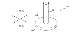
図10Aに示す穿刺補助部材303は筒状体である。より具体的に、図10Aに示す穿刺補助部材303は、筒本体部321と、この筒本体部321の軸方向Bの先端の位置で、筒本体部321から径方向Aの外側に突出するフランジ部322と、を備えている。そして、針部材2の穿刺時に生体表面BS(図2参照)に当接する当接部303aは、フランジ部322により構成されている。フランジ部322の外形は、図10Aに示す四角形状に限らず、任意の形状とすることができる。例えば、図10Bの示すような四角形状以外の多角形状であってもよく、図10Cに示すような円形状又は楕円形状などであってもよい。 Puncture assisting member 303 shown in FIG. 10A is a tubular body. More specifically, the puncture assisting member 303 shown in FIG. 10A includes a cylinder body portion 321 and a flange protruding outward in the radial direction A from the cylinder body portion 321 at the tip of the cylinder body portion 321 in the axial direction B. a portion 322; The abutting portion 303a that abuts on the body surface BS (see FIG. 2) when the needle member 2 is punctured is constituted by a flange portion 322. As shown in FIG. The external shape of the flange portion 322 is not limited to the rectangular shape shown in FIG. 10A, and may be any shape. For example, it may have a polygonal shape other than a square shape as shown in FIG. 10B, or may have a circular shape or an elliptical shape as shown in FIG. 10C.

図11は、図1に示す穿刺補助部材3の更に別の変形例としての穿刺補助部材403を示す図である。図11に示す穿刺補助部材403は、規制位置において、可撓部10のみならず、針部材2の先端の径方向A外側に周囲を覆っている。より具体的に、図11穿刺補助部材403は、規制位置において、可撓部10のみならず、針部材2全体の径方向Aの外側の周囲を覆っている。規制位置にある穿刺補助部材403が針部材2の先端の径方向A外側の周囲を覆う構成とすれば、穿刺を行う穿刺者が、穿刺前の針部材2の先端である針先に触れることを抑制することができる。また、このような構成とした場合には、上述した付勢部材6(図1、図2参照)を共に設けることが好ましい。このようにすれば、穿刺補助部材403は、針部材2の抜去時に、針部材2の針先の径方向A外側の周囲を覆う位置に復元する。そのため、針部材2の抜去後においても、針部材2の先端に指先が触れるリスクを低減することができる。 FIG. 11 is a diagram showing a puncture assist member 403 as still another modified example of the puncture assist member 3 shown in FIG. The puncture assisting member 403 shown in FIG. 11 covers not only the flexible portion 10 but also the distal end of the needle member 2 in the radial direction A in the restricting position. More specifically, the puncture assisting member 403 shown in FIG. 11 covers not only the flexible portion 10 but also the needle member 2 as a whole in the radial direction A at the restricted position. If the puncture assisting member 403 in the restricted position is configured to cover the outer periphery in the radial direction A of the distal end of the needle member 2, the puncture person who performs the puncture touches the needle tip, which is the distal end of the needle member 2 before puncturing. can be suppressed. Moreover, in the case of such a configuration, it is preferable to provide the aforementioned biasing member 6 (see FIGS. 1 and 2) together. In this way, when the needle member 2 is removed, the puncture assisting member 403 is restored to the position covering the outer periphery in the radial direction A of the tip of the needle member 2 . Therefore, even after the needle member 2 is removed, the risk of the tip of the needle member 2 being touched by the tip of the finger can be reduced.

図12A、図12B、図12Cは、図1に示す穿刺補助部材3の別の変形例としての穿刺補助部材を示す図である。図12Aに示す穿刺補助部材503は、筒状体である。但し、穿刺補助部材503としての筒状体の側壁には、軸方向Bにおいて筒状体の基端まで延在するスリット523が形成されている。このようなスリット523を設ければ、例えば処理装置5と共に使用する場合に、処理装置5の電気配線や筺体等との干渉を避ける構成とすることができる。スリット523の位置、大きさ、形状等は、処理装置5(図1等参照)の電気配線や筺体の位置、大きさ、形状等に応じて適宜設計することができる。また、スリット523は、処理装置5以外の装置と共に使用する場合であっても、装置本体5aを着脱可能な構成とする場合であっても、検出部材4から伸びる電気配線や筺体等と干渉を避けるように利用できるため有益である。 12A, 12B, and 12C are diagrams showing a puncture assist member as another modification of the puncture assist member 3 shown in FIG. Puncture assisting member 503 shown in FIG. 12A is a tubular body. However, a slit 523 extending in the axial direction B to the base end of the tubular body is formed in the side wall of the tubular body as the puncture assisting member 503 . If such a slit 523 is provided, for example, when used together with the processing device 5 , it is possible to avoid interference with the electrical wiring, housing, etc. of the processing device 5 . The position, size, shape, etc. of the slit 523 can be appropriately designed according to the position, size, shape, etc. of the electrical wiring and housing of the processing device 5 (see FIG. 1, etc.). In addition, even when the slit 523 is used together with a device other than the processing device 5, and when the device main body 5a is detachable, the slit 523 does not interfere with the electrical wiring extending from the detection member 4, the housing, and the like. It is useful because it can be used to avoid it.

図12Bに示す穿刺補助部材603は、螺旋状に旋回されて形成されており、全体として筒状の形状を有している。このような穿刺補助部材603を捩じりながら、針部材2の穿刺を実行するようにすれば、針部材2の可撓部10を、穿刺補助部材603により径方向A内側に圧縮することができる。つまり、可撓部10の位置での変形を、より抑制することができる。そのため、針部材2の穿刺時に、可撓部10に折れや曲げ等が発生する可能性を、より一層低減することができる。 Puncture assisting member 603 shown in FIG. 12B is formed by spirally turning, and has a tubular shape as a whole. If the needle member 2 is punctured while the puncture assisting member 603 is twisted, the flexible portion 10 of the needle member 2 can be compressed inward in the radial direction A by the puncture assisting member 603 . can. That is, deformation at the position of the flexible portion 10 can be further suppressed. Therefore, it is possible to further reduce the possibility that the flexible portion 10 will be broken or bent when the needle member 2 is punctured.

図12Cに示す穿刺補助部材703は、周方向Cにおいて異なる位置に配置された複数(図12Cでは2つ)の板部724により構成されている。複数の板部724は、針部材2の径方向Aの外側の位置に配置されており、周方向Cにおいて等間隔を空けて配置されている。図13は、図12Cに示す針部材2及び穿刺補助部材703を軸方向Bに見た図である。図13に示すように、穿刺補助部材703は、周方向Cに沿って湾曲している2つの板部724により構成されているが、規制位置にある穿刺補助部材703が可撓部10の径方向Aへの変形を規制できれば、板部の個数、形状は特に限定されない。 Puncture assisting member 703 shown in FIG. 12C is composed of a plurality of (two in FIG. 12C) plate portions 724 arranged at different positions in circumferential direction C. As shown in FIG. The plurality of plate portions 724 are arranged at outer positions in the radial direction A of the needle member 2 and are arranged at equal intervals in the circumferential direction C. As shown in FIG. 13 is a view of the needle member 2 and the puncture assisting member 703 shown in FIG. 12C viewed in the axial direction B. FIG. As shown in FIG. 13, the assisting puncture member 703 is composed of two plate portions 724 that are curved along the circumferential direction C. The assisting puncture member 703 at the regulated position is larger than the diameter of the flexible portion 10 . The number and shape of the plate portions are not particularly limited as long as the deformation in the direction A can be regulated.

図14、図15は、図1に示す穿刺補助部材3の別の変形例としての穿刺補助部材803を示す図である。図14、図15に示す穿刺補助部材803は、図1に示す穿刺補助部材3と比較して、処理装置5内に収容された際に処理装置5に設けられている第1係止部825により係止される被係止部826を備える点で、形状が相違している。換言すれば、処理装置5は、許容位置にある穿刺補助部材803を係止する第1係止部825を備えている。図14は、針部材2が穿刺途中であり、穿刺補助部材803が規制位置にある状態を示している。図15は、針部材2の穿刺が完了し、穿刺補助部材803が許容位置にある状態を示している。 14 and 15 are diagrams showing a puncture assist member 803 as another modification of the puncture assist member 3 shown in FIG. Puncture assist member 803 shown in FIGS. 14 and 15 differs from puncture assist member 3 shown in FIG. The shape is different in that a locked portion 826 that is locked by is provided. In other words, the processing device 5 includes a first locking portion 825 that locks the puncture assisting member 803 in the allowable position. FIG. 14 shows a state in which the needle member 2 is in the middle of puncturing and the puncture assisting member 803 is in the restricted position. FIG. 15 shows a state in which puncturing by the needle member 2 is completed and the puncture assisting member 803 is in the permissible position.

より具体的に、穿刺補助部材803は、筒本体部827と、この筒本体部827から径方向Aの外側に突出する被係止部826と、を備えている。被係止部826は、例えば周方向Cの一部のみに設けられた突起としてもよく、周方向C全域に亘って設けられた環状リブとしてもよい。図14、図15に示すように、穿刺補助部材803は、針部材2の穿刺時において、処理装置5の収容部内に移動する。この際に、被係止部826は、処理装置5の収容部の内壁に形成された第1係止部825を摺動しながら乗り越える。そのため、針部材2を抜去しても、穿刺補助部材803は、処理装置5に係止された状態が維持され、規制位置に戻らない。第1係止部825は、例えば、処理装置5の収容部の内壁に形成された突起により構成することができる。 More specifically, the puncture assisting member 803 includes a tubular main body portion 827 and an engaged portion 826 protruding outward in the radial direction A from the tubular main body portion 827 . The engaged portion 826 may be, for example, a projection provided only partially in the circumferential direction C, or may be an annular rib provided over the entire circumferential direction C. As shown in FIG. As shown in FIGS. 14 and 15 , the puncture assisting member 803 moves into the accommodating portion of the processing device 5 when the needle member 2 punctures. At this time, the locked portion 826 slides over the first locking portion 825 formed on the inner wall of the housing portion of the processing device 5 . Therefore, even if the needle member 2 is pulled out, the assisting member 803 remains engaged with the processing device 5 and does not return to the restricting position. The first locking portion 825 can be configured by, for example, a projection formed on the inner wall of the housing portion of the processing device 5 .

更に、図14、図15に示す処理装置5は、規制位置にある穿刺補助部材803を係止する第2係止部836を備えている。図14、図15に示す第2係止部836は、処理装置5の収容部の内壁に形成された環状リブにより構成されている。穿刺補助部材803の被係止部826と第2係止部836とは、軸方向Bにおいて重なる位置に形成されている。そのため、処理装置5から穿刺補助部材803を離間するように両者を軸方向Bに遠ざけると、穿刺補助部材803の被係止部826と処理装置5の第2係止部836とが係合する。このように、処理装置5が第2係止部836を備えることにより、許容位置にある穿刺補助部材803が処理装置5から離間しない。そのため、穿刺補助部材803が処理装置5から意図せずに離間することを抑制することができる。 Furthermore, the processing device 5 shown in FIGS. 14 and 15 includes a second locking portion 836 that locks the puncture assisting member 803 in the restricted position. The second locking portion 836 shown in FIGS. 14 and 15 is configured by an annular rib formed on the inner wall of the housing portion of the processing device 5 . The engaged portion 826 and the second engaging portion 836 of the puncture assisting member 803 are formed at positions where they overlap in the axial direction B. As shown in FIG. Therefore, when the assisting member 803 is moved away from the processing device 5 in the axial direction B, the engaged portion 826 of the assisting puncturing member 803 and the second engaging portion 836 of the processing device 5 are engaged. . In this way, the processing device 5 is provided with the second locking portion 836 so that the puncture assisting member 803 in the allowable position does not separate from the processing device 5 . Therefore, it is possible to prevent the puncture assist member 803 from unintentionally separating from the processing device 5 .

図16は、図1に示す穿刺補助部材3の別の変形例としての穿刺補助部材903を示す図である。図16に示す穿刺補助部材903は、図10A~図10Cに示す穿刺補助部材303のフランジ部322が、ベースプレートと一体に構成された例を示している。つまり、図16に示す穿刺補助部材903についても、筒本体部921と、この筒本体部921の軸方向Bの先端の位置で、筒本体部921から径方向Aの外側に突出するフランジ部922としてのベースプレートと、を備えている。そして、針部材2の穿刺時に生体表面BS(図2参照)に当接する当接部903aは、フランジ部922としてのベースプレートにより構成されている。換言すれば、図16に示す例では、ベースプレートは処理装置5の一部ではなく、穿刺補助部材903の一部を構成している。そして、図16に示すフランジ部322としてのベースプレートは、針部材2の穿刺時に、針部材2に対して軸方向Bの基端方向B1に移動する。 FIG. 16 shows a puncture assist member 903 as another modified example of the puncture assist member 3 shown in FIG. Puncture assist member 903 shown in FIG. 16 shows an example in which flange portion 322 of puncture assist member 303 shown in FIGS. 10A to 10C is configured integrally with a base plate. 16 also includes a cylinder body portion 921 and a flange portion 922 projecting outward in the radial direction A from the cylinder body portion 921 at the tip of the cylinder body portion 921 in the axial direction B. As a base plate and a. The abutment portion 903a that abuts on the surface of the living body BS (see FIG. 2) when the needle member 2 is punctured is composed of a base plate as a flange portion 922. As shown in FIG. In other words, in the example shown in FIG. 16, the base plate forms part of the puncture assisting member 903 instead of part of the processing device 5 . 16 moves in the proximal direction B1 of the axial direction B with respect to the needle member 2 when the needle member 2 is punctured.

図16に示す穿刺補助部材903は、上述した筒本体部921及びフランジ部922の他に、筒本体部921の径方向Aの外側の位置で、フランジ部922から処理装置5に向かって突設された被係止部928を備えている。被係止部928は、穿刺補助部材903が規制位置(図16参照)から許容位置になることで、処理装置5内に収容される。そして、処理装置5内に収容された際に、処理装置5に設けられている第1係止部929により係止される。換言すれば、処理装置5は、許容位置にある穿刺補助部材903を係止する第1係止部929を備えている。より具体的に、図16に示す被係止部928は、フランジ部922から突出する本体部928aと、この本体部928aの径方向Aの内側に設けられた爪部928bと、を備えている。また、図16に示す第1係止部929は、被係止部928を収容する処理装置5の収容部の内壁に形成された突起により構成することができる。 The puncture assisting member 903 shown in FIG. 16 protrudes from the flange portion 922 toward the processing device 5 at a position outside the cylinder body portion 921 in the radial direction A, in addition to the cylinder body portion 921 and the flange portion 922 described above. A locked portion 928 is provided. Locked portion 928 is accommodated in processing device 5 when puncturing assist member 903 moves from the restricted position (see FIG. 16) to the permitted position. Then, when housed in the processing device 5 , it is locked by the first locking portion 929 provided in the processing device 5 . In other words, the processing device 5 includes a first locking portion 929 that locks the puncture assisting member 903 in the allowable position. More specifically, the engaged portion 928 shown in FIG. 16 includes a body portion 928a projecting from the flange portion 922 and a claw portion 928b provided inside the body portion 928a in the radial direction A. . 16 can be configured by a protrusion formed on the inner wall of the housing portion of the processing device 5 that houses the locked portion 928. The first locking portion 929 shown in FIG.

更に、図16に示す処理装置5は、規制位置にある穿刺補助部材903を係止する第2係止部937を備えている。図16に示す第2係止部937は、処理装置5の収容部の内壁に形成された環状リブにより構成されている。穿刺補助部材903の被係止部928と第2係止部937とは、軸方向Bにおいて重なる位置に形成されている。そのため、処理装置5から穿刺補助部材903を離間するように両者を軸方向Bに遠ざけると、穿刺補助部材903の被係止部928と処理装置5の第2係止部937とが係合する。このように、処理装置5が第2係止部937を備えることにより、許容位置にある穿刺補助部材903が処理装置5から離間しない。そのため、穿刺補助部材903が処理装置5から意図せずに離間することを抑制することができる。 Furthermore, the processing device 5 shown in FIG. 16 includes a second locking portion 937 that locks the puncture assisting member 903 in the restricted position. The second locking portion 937 shown in FIG. 16 is configured by an annular rib formed on the inner wall of the accommodation portion of the processing device 5 . The engaged portion 928 and the second engaging portion 937 of the puncture assisting member 903 are formed at positions where they overlap in the axial direction B. As shown in FIG. Therefore, when the assisting member 903 is moved away from the processing device 5 in the axial direction B, the engaged portion 928 of the assisting puncturing member 903 and the second engaging portion 937 of the processing device 5 are engaged. . In this manner, the processing device 5 is provided with the second locking portion 937 so that the puncture assisting member 903 in the allowable position does not separate from the processing device 5 . Therefore, it is possible to prevent the puncture assist member 903 from unintentionally separating from the processing device 5 .

被係止部928としては、図17Aに示すように、周方向Cに間隔を空けて複数配置した構成としてもよい。また、図17Bに示すように、周方向C全域に亘って延在する環状の構成としてもよい。図17A、図17Bは、穿刺補助部材903を、処理装置5側(図16の上側)から見た図である。 As shown in FIG. 17A, a plurality of locked portions 928 may be arranged at intervals in the circumferential direction C. As shown in FIG. Moreover, as shown in FIG. 17B, it may have an annular configuration extending over the entire circumferential direction C. FIG. 17A and 17B are views of the puncture assisting member 903 as seen from the processing device 5 side (upper side in FIG. 16).

本開示に係る穿刺装置は、上述した具体的な構成に限られず、特許請求の範囲の記載を逸脱しない限り、種々の変形・変更が可能である。例えば、図1~図17に示す穿刺装置では、針部材が、処理装置の中央位置から突設されているが、この構成に限らず、図18に示すように、処理装置5の中央位置以外の位置から突設されている針部材1002としてもよい。また、図1~図17に示す穿刺装置では、針部材が、扁平な処理装置の厚み方向に突出しているが、この構成に限らず、図19に示すように、扁平な処理装置5の厚み方向に対して傾斜して突出する針部材1102としてもよい。このような針部材1102とする場合は、生体表面BS(図2参照)の処理装置5は、穿刺されている針部材1102の軸方向Bに沿うように、生体表面BS上を移動し易い。つまり、図19に示す例では、外力により、処理装置5が左右方向に移動し易い。そのため、針部材1102に設ける可撓部としては、生体表面BS上で軸方向Bに沿う方向(図19では左右方向)に変形し易い構成とすることが好ましい。また、穿刺補助部材1103の当接部1103aを構成する軸方向Bの先端面は、針部材1102の穿刺動作時に生体表面BSに当接し易いように、処理装置5のベースプレート5bの下面5b1と略平行する角度に形成されている。 The puncture device according to the present disclosure is not limited to the specific configuration described above, and various modifications and changes are possible without departing from the scope of claims. For example, in the puncture device shown in FIGS. 1 to 17, the needle member protrudes from the central position of the processing device. A needle member 1002 projecting from the position of . In the puncture device shown in FIGS. 1 to 17, the needle member protrudes in the thickness direction of the flat processing device. The needle member 1102 may project obliquely with respect to the direction. When such a needle member 1102 is used, the processing device 5 for the living body surface BS (see FIG. 2) can easily move on the living body surface BS along the axial direction B of the punctured needle member 1102 . That is, in the example shown in FIG. 19, the processing device 5 is likely to move in the left-right direction due to an external force. Therefore, it is preferable that the flexible portion provided on the needle member 1102 be configured so as to easily deform in the direction along the axial direction B (horizontal direction in FIG. 19) on the body surface BS. In addition, the distal end surface of the abutting portion 1103a of the puncture assisting member 1103 in the axial direction B is approximately the same as the lower surface 5b1 of the base plate 5b of the processing device 5 so that the needle member 1102 can easily abut against the living body surface BS during the puncturing operation. formed at parallel angles.

また、図1~図19では、穿刺装置としての計測装置について説明しているが、検出部材を備えない別の穿刺装置であってもよい。但し、穿刺装置として、検出部材を備える計測装置とすれば、上述したように、可撓部を設ける構成とすることで検出部材による検出精度の低下を抑制することができる。 In addition, although FIGS. 1 to 19 describe the measuring device as a puncture device, another puncture device that does not include a detection member may be used. However, if the puncture device is a measuring device that includes a detection member, it is possible to suppress a decrease in detection accuracy by the detection member by providing a flexible portion as described above.

本開示は穿刺装置に関する。 The present disclosure relates to lancing devices.

1:穿刺装置
2、1002、1102:針部材
2a:刃面
2b:貫通孔
3、103、203、303、403、503、603、703、803、903、1103:穿刺補助部材
3a、103a、203a、303a、903a、1103a:当接部
4:検出部材
4a:第1検出部材
4b:第2検出部材
5:処理装置
5a:装置本体
5b:ベースプレート
5b1:ベースプレートの下面
5b2:ベースプレートの上面
6:付勢部材
10、110、210、310、410、510、610:可撓部
11、111、211、311、511:スリット
111a:突出スリット部
111a1:第1部分
111a2:第2部分
111a3:第3部分
111b:連結スリット部
112a、212a:第1突出部
112b、212b:第2突出部
113a:第1谷底縁部
113b:第2谷底縁部
211a:第1突出スリット部
211a1:第1部分
211a2:第2部分
211a3:第3部分
211b:第2突出スリット部
211b1:第1部分
211b2:第2部分
211b3:第3部分
213:谷底縁部
214:介在部
215a:第1対向部
215b:第2対向部
217:筒部
217a:第1筒部
217b:第2筒部
217c:第3筒部
217d:第4筒部
218:筒本体部
219、219d:内側係合部
220、220c:外側係合部
230:内側基部
231、231d:内側先端部
232:内側凹部
233:外側基部
234:外側先端部
235、235c:外側凹部
311a:第1突出スリット部
311a1:第1部分
311a2:第2部分
311b:第2突出スリット部
321:筒本体部
322:フランジ部
411a:第1突出スリット部
411b:第2突出スリット部
516a:第1スリット群
516b:第2スリット群
523:スリット
611:周溝
724:板部
825:第1係止部
826:被係止部
827:筒本体部
836:第2係止部
921:筒部本体
922:フランジ部
928:被係止部
928a:本体部
928b:爪部
929:第1係止部
937:第2係止部
A:針部材の径方向
B:針部材の軸方向
B1:基端方向
B2:先端方向
C:針部材の周方向
D:螺旋方向
D1:第1旋回方向
D2:第2旋回方向
cp:中心点
BS:生体表面
S1:軸方向におけるスリットが形成されている部分
W1:当接部の最大幅
1: Puncture device 2, 1002, 1102: Needle member 2a: Blade surface 2b: Through hole 3, 103, 203, 303, 403, 503, 603, 703, 803, 903, 1103: Puncture auxiliary member 3a, 103a, 203a , 303a, 903a, 1103a: contact portion 4: detection member 4a: first detection member 4b: second detection member 5: processing device 5a: apparatus body 5b: base plate 5b1: base plate lower surface 5b2: base plate upper surface 6: attached Force member 10, 110, 210, 310, 410, 510, 610: flexible portion 11, 111, 211, 311, 511: slit 111a: projecting slit portion 111a1: first portion 111a2: second portion 111a3: third portion 111b: connecting slit portions 112a, 212a: first projecting portions 112b, 212b: second projecting portion 113a: first valley bottom edge portion 113b: second valley bottom edge portion 211a: first projecting slit portion 211a1: first portion 211a2: second 2 parts 211a3: 3rd part 211b: 2nd projecting slit part 211b1: 1st part 211b2: 2nd part 211b3: 3rd part 213: Valley bottom edge 214: Interposed part 215a: First facing part 215b: Second facing part 217: cylinder portion 217a: first cylinder portion 217b: second cylinder portion 217c: third cylinder portion 217d: fourth cylinder portion 218: cylinder body portions 219, 219d: inner engagement portions 220, 220c: outer engagement portion 230 : Inner base 231, 231d: Inner tip 232: Inner recess 233: Outer base 234: Outer tip 235, 235c: Outer recess 311a: First protruding slit 311a1: First part 311a2: Second part 311b: Second Protruding slit portion 321: cylinder body portion 322: flange portion 411a: first protruding slit portion 411b: second protruding slit portion 516a: first slit group 516b: second slit group 523: slit 611: circumferential groove 724: plate portion 825 : First locking portion 826: Locked portion 827: Cylinder main body portion 836: Second locking portion 921: Cylinder main body 922: Flange portion 928: Locked portion 928a: Main body portion 928b: Claw portion 929: Third 1 locking portion 937: second locking portion A: radial direction of needle member B: axial direction of needle member B1: proximal direction B2: distal direction C: circumferential direction of needle member D: spiral direction D1: first turning Direction D2: Second turning direction cp: Center point BS: Biological surface S1: Portion W1 where slit is formed in axial direction: Maximum width of contact portion

Claims (13)

変形可能な可撓部を備える管状の針部材と、
前記可撓部に対して前記針部材の径方向の外側で、前記可撓部の変形を規制する規制位置、及び、前記可撓部に対して前記径方向の外側に位置せず、前記可撓部の変形を許容する許容位置、の間で、前記針部材の軸方向に移動又は変形可能な穿刺補助部材と、
前記針部材の中空部に位置し、生体内の被計測物質を検出可能な検出部材と、
前記検出部材により検出された情報を処理する処理装置と、を備え、
前記穿刺補助部材は、前記針部材の穿刺時に、前記可撓部が生体内に挿入される動作と連動して、前記規制位置から前記許容位置へと移動又は変形し、
前記針部材は、前記処理装置に固定されており、
前記穿刺補助部材は、前記処理装置に対して、前記軸方向に移動又は変形可能に取り付けられており、
前記処理装置は、前記規制位置にある前記穿刺補助部材を係止する係止部を備える、穿刺装置。
a tubular needle member having a deformable flexible portion;
a restricting position that restricts deformation of the flexible portion outside the needle member in the radial direction with respect to the flexible portion; a puncture assisting member movable or deformable in the axial direction of the needle member between permissible positions that permit deformation of the flexible portion;
a detection member positioned in the hollow portion of the needle member and capable of detecting a substance to be measured in a living body;
a processing device for processing information detected by the detection member ,
The puncture assist member moves or deforms from the restricted position to the allowable position in conjunction with the insertion of the flexible portion into the living body when the needle member is punctured ,
The needle member is fixed to the processing device,
The puncture assisting member is attached to the processing device so as to be movable or deformable in the axial direction,
The puncture device, wherein the processing device includes a locking portion that locks the puncture assist member at the restricted position .
前記穿刺補助部材は、前記軸方向の先端に位置し、前記針部材の穿刺時に生体表面に当接する当接部を備え、
前記当接部の前記径方向の最大幅は、前記穿刺補助部材の前記当接部以外の位置での前記径方向の最大幅よりも大きい、請求項1に記載の穿刺装置。
The puncture assisting member has an abutment portion located at the distal end in the axial direction and abutting against the surface of the living body when the needle member punctures,
The puncture device according to claim 1, wherein the maximum radial width of the contact portion is larger than the maximum radial width of the puncture assist member at a position other than the contact portion.
前記穿刺補助部材は筒状体であり、前記穿刺補助部材の外径は、前記軸方向の基端側から先端の前記当接部に向かうにつれて漸増している、請求項2に記載の穿刺装置。 3. The puncture device according to claim 2, wherein the puncture assist member is a tubular body, and the outer diameter of the puncture assist member gradually increases from the base end side in the axial direction toward the contact portion at the distal end. . 前記筒状体は、前記径方向に複数の筒部が同心円状に重なり合って構成されており、前記複数の筒部が前記軸方向に移動することで前記軸方向の長さを変動可能なテレスコピック機構を有しており、
前記複数の筒部の外径のうち、前記当接部を含む筒部の外径が最大である、請求項3に記載の穿刺装置。
The tubular body is configured by overlapping a plurality of tubular portions concentrically in the radial direction, and is telescopic in which the length in the axial direction can be varied by moving the tubular portions in the axial direction. have a mechanism,
4. The puncture device according to claim 3, wherein, among the outer diameters of the plurality of cylindrical portions, the cylindrical portion including the contact portion has the largest outer diameter.
前記穿刺補助部材は筒状体であり、筒本体部と、前記筒本体部の前記軸方向の先端の位置で、前記筒本体部から前記径方向の外側に突出するフランジ部と、を備え、
前記当接部は、前記フランジ部により構成されている、請求項2に記載の穿刺装置。
The puncture assisting member is a tubular body, and includes a tubular main body and a flange projecting outward in the radial direction from the tubular main body at a position of the tip of the tubular main body in the axial direction,
3. The puncture device according to claim 2, wherein the contact portion is configured by the flange portion.
前記穿刺補助部材は筒状体であり、前記軸方向において基端まで延在するスリットが形成されている、請求項1に記載の穿刺装置。 2. The puncture device according to claim 1, wherein said puncture assisting member is a tubular body, and is formed with a slit extending to a proximal end in said axial direction. 前記処理装置は扁平状であり、
前記針部材は、前記処理装置の厚み方向の一方側に突出した状態で固定されている、請求項1乃至6のいずれか1つに記載の穿刺装置。
The processing device is flat,
The puncture device according to any one of claims 1 to 6 , wherein the needle member is fixed in a state of protruding to one side in the thickness direction of the processing device.
前記許容位置にある前記穿刺補助部材を、前記規制位置に復元するように前記軸方向に付勢する付勢部材を備える、請求項1乃至7のいずれか1つに記載の穿刺装置。 The lancing device according to any one of claims 1 to 7 , further comprising a biasing member that biases said assisting puncture member in said allowable position in said axial direction so as to restore said assisting member in said restricting position. 前記可撓部は、前記針部材の前記軸方向における、螺旋状に延在するスリットが形成されている部分、により構成されている、請求項1乃至8のいずれか1つに記載の穿刺装置。 The puncture device according to any one of claims 1 to 8 , wherein the flexible portion is configured by a portion formed with a spirally extending slit in the axial direction of the needle member. . 前記スリットには、前記軸方向に向かって突出する突出スリット部が形成されている、請求項9に記載の穿刺装置。 10. The puncture device according to claim 9 , wherein the slit is formed with a projecting slit portion projecting in the axial direction. 前記突出スリット部を第1突出スリット部とした場合に、前記スリットには、前記針部材の周方向に向かって突出する第2突出スリット部が形成されている、請求項10に記載の穿刺装置。 11. The puncture device according to claim 10 , wherein when the protruding slit portion is the first protruding slit portion, the slit is formed with a second protruding slit portion protruding in the circumferential direction of the needle member. . 前記可撓部は、前記針部材の前記軸方向における、前記針部材の周方向に延びるスリットが形成されている部分、により構成されている、請求項1乃至8のいずれか1つに記載の穿刺装置。 9. The flexible portion according to any one of claims 1 to 8 , wherein the flexible portion is formed of a portion formed with a slit extending in the circumferential direction of the needle member in the axial direction of the needle member. lancing device. 前記可撓部は、前記針部材の前記軸方向における、前記針部材の周方向に延在する周溝が形成されている部分、により構成されている、請求項1乃至8のいずれか1つに記載の穿刺装置。 9. The flexible portion according to any one of claims 1 to 8 , wherein the flexible portion comprises a portion in the axial direction of the needle member, in which a circumferential groove extending in the circumferential direction of the needle member is formed. The lancing device according to .
JP2019540857A 2017-09-08 2018-08-16 lancing device Active JP7143305B2 (en)

Applications Claiming Priority (3)

Application Number Priority Date Filing Date Title
JP2017173451 2017-09-08
PCT/JP2018/030428 WO2019049628A1 (en) 2017-09-08 2018-08-16 Puncture device

Publications (2)

Publication Number Publication Date
JPWO2019049628A1 JPWO2019049628A1 (en) 2020-08-20
JP7143305B2 true JP7143305B2 (en) 2022-09-28

Family

ID=65633877

Family Applications (1)

Application Number Title Priority Date Filing Date
JP2019540857A Active JP7143305B2 (en) 2017-09-08 2018-08-16 lancing device

Country Status (4)

Country Link
US (1) US11534204B2 (en)
EP (1) EP3650061A4 (en)
JP (1) JP7143305B2 (en)
WO (1) WO2019049628A1 (en)

Families Citing this family (4)

* Cited by examiner, † Cited by third party
Publication number Priority date Publication date Assignee Title
US10932699B2 (en) * 2017-09-13 2021-03-02 Dexcom, Inc. Invasive biosensor alignment and retention
EP4048160A4 (en) * 2019-10-24 2023-11-01 Janssen Biotech, Inc. Steerable needles
KR20220131998A (en) * 2020-03-27 2022-09-29 니혼라이프라인 가부시키가이샤 Chemical injection needle and chemical liquid injection needle system
JP7373056B2 (en) 2020-03-27 2023-11-01 日本ライフライン株式会社 Chemical injection needles and chemical injection needle systems

Citations (5)

* Cited by examiner, † Cited by third party
Publication number Priority date Publication date Assignee Title
US20100249748A1 (en) 2009-03-30 2010-09-30 University Of Rochester Needle shield for injections
JP2012515016A (en) 2009-01-12 2012-07-05 ベクトン・ディキンソン・アンド・カンパニー Infusion set and / or patch pump having at least one of an internal rigid catheter and / or flexible catheter attachment with flexible features
JP2014200551A (en) 2013-04-08 2014-10-27 オリンパス株式会社 Puncture needle
JP2015518396A (en) 2012-04-11 2015-07-02 ファルマセンス アクチェンゲゼルシャフト Hypodermic needle insertion mechanism
JP2015529487A (en) 2012-07-26 2015-10-08 エージェンシー フォー サイエンス,テクノロジー アンド リサーチ Vascular access device and guide section

Family Cites Families (7)

* Cited by examiner, † Cited by third party
Publication number Priority date Publication date Assignee Title
DE102004002476B4 (en) * 2004-01-16 2005-12-08 Disetronic Licensing Ag Puncture Needle with Puncture Needle and Needle Guide
DE102004002472B4 (en) * 2004-01-16 2007-09-13 Disetronic Licensing Ag needle
CN100579598C (en) * 2004-12-06 2010-01-13 诺和诺德公司 Ventilated skin mountable device
CA3175799A1 (en) * 2011-02-09 2012-08-16 Becton, Dickinson And Company Subcutaneous infusion device
GB2500784B (en) * 2012-02-28 2015-07-22 Spiration Inc Lung Biopsy Needle
US9931065B2 (en) * 2012-04-04 2018-04-03 Dexcom, Inc. Transcutaneous analyte sensors, applicators therefor, and associated methods
JP6518671B2 (en) * 2013-12-13 2019-05-22 インテュイティブ サージカル オペレーションズ, インコーポレイテッド Nested biopsy needle

Patent Citations (5)

* Cited by examiner, † Cited by third party
Publication number Priority date Publication date Assignee Title
JP2012515016A (en) 2009-01-12 2012-07-05 ベクトン・ディキンソン・アンド・カンパニー Infusion set and / or patch pump having at least one of an internal rigid catheter and / or flexible catheter attachment with flexible features
US20100249748A1 (en) 2009-03-30 2010-09-30 University Of Rochester Needle shield for injections
JP2015518396A (en) 2012-04-11 2015-07-02 ファルマセンス アクチェンゲゼルシャフト Hypodermic needle insertion mechanism
JP2015529487A (en) 2012-07-26 2015-10-08 エージェンシー フォー サイエンス,テクノロジー アンド リサーチ Vascular access device and guide section
JP2014200551A (en) 2013-04-08 2014-10-27 オリンパス株式会社 Puncture needle

Also Published As

Publication number Publication date
EP3650061A4 (en) 2020-07-01
JPWO2019049628A1 (en) 2020-08-20
EP3650061A1 (en) 2020-05-13
US20200170670A1 (en) 2020-06-04
US11534204B2 (en) 2022-12-27
WO2019049628A1 (en) 2019-03-14

Similar Documents

Publication Publication Date Title
JP7143305B2 (en) lancing device
JP7321139B2 (en) Pen needle outer cover concept
KR20090040920A (en) Medical needle device
US20100076378A1 (en) Safety Medical Syringe with Retractable Needle and Including a Plunger that is Received within a Barrel
JP6031285B2 (en) Waste container
JPWO2014199697A1 (en) Catheter assembly
WO2011122350A1 (en) Puncture needle and puncture tool
US11452843B2 (en) Device and method for injecting a biomaterial into body tissue
JP2020203068A (en) Blood collection tube holder and blood collection kit
JP7313228B2 (en) insertion device
WO2020250852A1 (en) Blood collection tube holder and blood collection kit
WO2019123698A1 (en) Protector and medical needle assembly
WO2013146868A1 (en) Disposal container
US20220047189A1 (en) Insertion device
US20220047304A1 (en) Insertion device and needle member
WO2020250859A1 (en) Blood collection tube holder and blood collection kit
WO2020250858A1 (en) Blood collection tube holder and blood collection kit
WO2020250853A1 (en) Blood collection tube holder and blood collection kit
JP7233219B2 (en) Syringe with patient contact surface
JPWO2019013045A1 (en) Medical device, medical system, and determination method
MXPA06009014A (en) Needle guard strut wall clip.

Legal Events

Date Code Title Description
A621 Written request for application examination

Free format text: JAPANESE INTERMEDIATE CODE: A621

Effective date: 20210520

A131 Notification of reasons for refusal

Free format text: JAPANESE INTERMEDIATE CODE: A131

Effective date: 20220628

A521 Request for written amendment filed

Free format text: JAPANESE INTERMEDIATE CODE: A523

Effective date: 20220815

TRDD Decision of grant or rejection written
A01 Written decision to grant a patent or to grant a registration (utility model)

Free format text: JAPANESE INTERMEDIATE CODE: A01

Effective date: 20220830

A61 First payment of annual fees (during grant procedure)

Free format text: JAPANESE INTERMEDIATE CODE: A61

Effective date: 20220914

R150 Certificate of patent or registration of utility model

Ref document number: 7143305

Country of ref document: JP

Free format text: JAPANESE INTERMEDIATE CODE: R150