JP7143272B2 - Free piston Stirling refrigerator - Google Patents
Free piston Stirling refrigerator Download PDFInfo
- Publication number
- JP7143272B2 JP7143272B2 JP2019232614A JP2019232614A JP7143272B2 JP 7143272 B2 JP7143272 B2 JP 7143272B2 JP 2019232614 A JP2019232614 A JP 2019232614A JP 2019232614 A JP2019232614 A JP 2019232614A JP 7143272 B2 JP7143272 B2 JP 7143272B2
- Authority
- JP
- Japan
- Prior art keywords
- piston
- current
- waveform
- detected
- alternating current
- Prior art date
- Legal status (The legal status is an assumption and is not a legal conclusion. Google has not performed a legal analysis and makes no representation as to the accuracy of the status listed.)
- Active
Links
Images


Classifications
-
- F—MECHANICAL ENGINEERING; LIGHTING; HEATING; WEAPONS; BLASTING
- F25—REFRIGERATION OR COOLING; COMBINED HEATING AND REFRIGERATION SYSTEMS; HEAT PUMP SYSTEMS; MANUFACTURE OR STORAGE OF ICE; LIQUEFACTION SOLIDIFICATION OF GASES
- F25B—REFRIGERATION MACHINES, PLANTS OR SYSTEMS; COMBINED HEATING AND REFRIGERATION SYSTEMS; HEAT PUMP SYSTEMS
- F25B9/00—Compression machines, plants or systems, in which the refrigerant is air or other gas of low boiling point
- F25B9/14—Compression machines, plants or systems, in which the refrigerant is air or other gas of low boiling point characterised by the cycle used, e.g. Stirling cycle
-
- F—MECHANICAL ENGINEERING; LIGHTING; HEATING; WEAPONS; BLASTING
- F02—COMBUSTION ENGINES; HOT-GAS OR COMBUSTION-PRODUCT ENGINE PLANTS
- F02G—HOT GAS OR COMBUSTION-PRODUCT POSITIVE-DISPLACEMENT ENGINE PLANTS; USE OF WASTE HEAT OF COMBUSTION ENGINES; NOT OTHERWISE PROVIDED FOR
- F02G1/00—Hot gas positive-displacement engine plants
- F02G1/04—Hot gas positive-displacement engine plants of closed-cycle type
- F02G1/043—Hot gas positive-displacement engine plants of closed-cycle type the engine being operated by expansion and contraction of a mass of working gas which is heated and cooled in one of a plurality of constantly communicating expansible chambers, e.g. Stirling cycle type engines
- F02G1/0435—Hot gas positive-displacement engine plants of closed-cycle type the engine being operated by expansion and contraction of a mass of working gas which is heated and cooled in one of a plurality of constantly communicating expansible chambers, e.g. Stirling cycle type engines the engine being of the free piston type
-
- F—MECHANICAL ENGINEERING; LIGHTING; HEATING; WEAPONS; BLASTING
- F02—COMBUSTION ENGINES; HOT-GAS OR COMBUSTION-PRODUCT ENGINE PLANTS
- F02G—HOT GAS OR COMBUSTION-PRODUCT POSITIVE-DISPLACEMENT ENGINE PLANTS; USE OF WASTE HEAT OF COMBUSTION ENGINES; NOT OTHERWISE PROVIDED FOR
- F02G1/00—Hot gas positive-displacement engine plants
- F02G1/04—Hot gas positive-displacement engine plants of closed-cycle type
- F02G1/043—Hot gas positive-displacement engine plants of closed-cycle type the engine being operated by expansion and contraction of a mass of working gas which is heated and cooled in one of a plurality of constantly communicating expansible chambers, e.g. Stirling cycle type engines
- F02G1/045—Controlling
-
- F—MECHANICAL ENGINEERING; LIGHTING; HEATING; WEAPONS; BLASTING
- F25—REFRIGERATION OR COOLING; COMBINED HEATING AND REFRIGERATION SYSTEMS; HEAT PUMP SYSTEMS; MANUFACTURE OR STORAGE OF ICE; LIQUEFACTION SOLIDIFICATION OF GASES
- F25B—REFRIGERATION MACHINES, PLANTS OR SYSTEMS; COMBINED HEATING AND REFRIGERATION SYSTEMS; HEAT PUMP SYSTEMS
- F25B49/00—Arrangement or mounting of control or safety devices
-
- F—MECHANICAL ENGINEERING; LIGHTING; HEATING; WEAPONS; BLASTING
- F02—COMBUSTION ENGINES; HOT-GAS OR COMBUSTION-PRODUCT ENGINE PLANTS
- F02G—HOT GAS OR COMBUSTION-PRODUCT POSITIVE-DISPLACEMENT ENGINE PLANTS; USE OF WASTE HEAT OF COMBUSTION ENGINES; NOT OTHERWISE PROVIDED FOR
- F02G2275/00—Controls
-
- F—MECHANICAL ENGINEERING; LIGHTING; HEATING; WEAPONS; BLASTING
- F02—COMBUSTION ENGINES; HOT-GAS OR COMBUSTION-PRODUCT ENGINE PLANTS
- F02G—HOT GAS OR COMBUSTION-PRODUCT POSITIVE-DISPLACEMENT ENGINE PLANTS; USE OF WASTE HEAT OF COMBUSTION ENGINES; NOT OTHERWISE PROVIDED FOR
- F02G2280/00—Output delivery
- F02G2280/10—Linear generators
-
- F—MECHANICAL ENGINEERING; LIGHTING; HEATING; WEAPONS; BLASTING
- F25—REFRIGERATION OR COOLING; COMBINED HEATING AND REFRIGERATION SYSTEMS; HEAT PUMP SYSTEMS; MANUFACTURE OR STORAGE OF ICE; LIQUEFACTION SOLIDIFICATION OF GASES
- F25B—REFRIGERATION MACHINES, PLANTS OR SYSTEMS; COMBINED HEATING AND REFRIGERATION SYSTEMS; HEAT PUMP SYSTEMS
- F25B2309/00—Gas cycle refrigeration machines
- F25B2309/001—Gas cycle refrigeration machines with a linear configuration or a linear motor
-
- F—MECHANICAL ENGINEERING; LIGHTING; HEATING; WEAPONS; BLASTING
- F25—REFRIGERATION OR COOLING; COMBINED HEATING AND REFRIGERATION SYSTEMS; HEAT PUMP SYSTEMS; MANUFACTURE OR STORAGE OF ICE; LIQUEFACTION SOLIDIFICATION OF GASES
- F25B—REFRIGERATION MACHINES, PLANTS OR SYSTEMS; COMBINED HEATING AND REFRIGERATION SYSTEMS; HEAT PUMP SYSTEMS
- F25B2700/00—Sensing or detecting of parameters; Sensors therefor
- F25B2700/15—Power, e.g. by voltage or current
-
- H—ELECTRICITY
- H02—GENERATION; CONVERSION OR DISTRIBUTION OF ELECTRIC POWER
- H02P—CONTROL OR REGULATION OF ELECTRIC MOTORS, ELECTRIC GENERATORS OR DYNAMO-ELECTRIC CONVERTERS; CONTROLLING TRANSFORMERS, REACTORS OR CHOKE COILS
- H02P27/00—Arrangements or methods for the control of AC motors characterised by the kind of supply voltage
- H02P27/04—Arrangements or methods for the control of AC motors characterised by the kind of supply voltage using variable-frequency supply voltage, e.g. inverter or converter supply voltage
- H02P27/06—Arrangements or methods for the control of AC motors characterised by the kind of supply voltage using variable-frequency supply voltage, e.g. inverter or converter supply voltage using dc to ac converters or inverters
-
- H—ELECTRICITY
- H02—GENERATION; CONVERSION OR DISTRIBUTION OF ELECTRIC POWER
- H02P—CONTROL OR REGULATION OF ELECTRIC MOTORS, ELECTRIC GENERATORS OR DYNAMO-ELECTRIC CONVERTERS; CONTROLLING TRANSFORMERS, REACTORS OR CHOKE COILS
- H02P29/00—Arrangements for regulating or controlling electric motors, appropriate for both AC and DC motors
- H02P29/02—Providing protection against overload without automatic interruption of supply
- H02P29/024—Detecting a fault condition, e.g. short circuit, locked rotor, open circuit or loss of load
- H02P29/026—Detecting a fault condition, e.g. short circuit, locked rotor, open circuit or loss of load the fault being a power fluctuation
Landscapes
- Engineering & Computer Science (AREA)
- Mechanical Engineering (AREA)
- General Engineering & Computer Science (AREA)
- Physics & Mathematics (AREA)
- Thermal Sciences (AREA)
- Chemical & Material Sciences (AREA)
- Combustion & Propulsion (AREA)
- Control Of Linear Motors (AREA)
- Inverter Devices (AREA)
Description
本発明は、フリーピストン型スターリング冷凍機に関するものであり、特に、ピストンとディスプレイサーとが圧縮室を隔てて直接対向して配されているフリーピストン型スターリング冷凍機に関するものである。 The present invention relates to a free-piston Stirling refrigerator, and more particularly to a free-piston Stirling refrigerator in which a piston and a displacer are directly opposed to each other with a compression chamber therebetween.
従来、この種のフリーピストン型スターリング冷凍機としては、ケーシングと、このケーシング内に設けられるシリンダと、このシリンダ内を往復動可能に設けられるピストンと、このピストンを往復動させるリニアモータと、前記ピストンの往復動に伴って前記シリンダ内を往復動するディスプレイサーと、前記リニアモータの動作を制御する制御手段とを有するものが知られている(例えば、特許文献1、2参照。)。このようなフリーピストン型スターリング冷凍機は、前記ピストンの振幅が定まっておらず、前記リニアモータに供給される電力等によって振幅が変動する。同様に、前記ディスプレイサーの振幅も定まっておらず、前記リニアモータに供給される電力等によって振幅が変動する。なお、前記ピストン及びディスプレイサーの振幅は、吸熱部や排熱部の温度等によっても変動する。このため、特許文献1では、吸熱部及び排熱部の温度に基づいて前記リニアモータに供給される電力を制御し、前記ピストンとディスプレイサーの相互の衝突或いは前記ピストン及び/又はディスプレイサーと他の部位との衝突(以下、「ヒッティング」とする。)を抑止している。また、特許文献2では、ピストン及びディスプレイサーの位置を連続的に演算で求め、この演算結果に基づいて前記リニアモータに供給される電力を制御し、ヒッティングを抑止している。なお、特許文献2において、ピストン及びディスプレイサーの位置を連続的に演算で求めるため、電流及び電圧検知手段、又は静電容量を検知する手段、又は光学センサ等が必要となる。
Conventionally, this type of free-piston Stirling refrigerator includes a casing, a cylinder provided in the casing, a piston provided to reciprocate in the cylinder, a linear motor for reciprocating the piston, and the There is known one that has a displacer that reciprocates in the cylinder with the reciprocating motion of the piston and control means that controls the operation of the linear motor (see, for example,
しかしながら、これらのようなフリーピストン型スターリング冷凍機では、制御のための物理量を検出する手段が必要になったり、演算が複雑になったりする問題があった。そして、このため、フリーピストン型スターリング冷凍機のシステムが複雑になったり高価になったりするという問題があった。 However, such free-piston Stirling refrigerators have problems such as the necessity of means for detecting physical quantities for control and the complexity of calculations. As a result, there is a problem that the system of the free piston Stirling refrigerator becomes complicated and expensive.
本発明は以上の問題点を解決し、単純で安価な手段でヒッティングを抑制することができるフリーピストン型スターリング冷凍機を提供することを目的とする。 SUMMARY OF THE INVENTION An object of the present invention is to solve the above problems and to provide a free-piston Stirling refrigerator capable of suppressing the hitting by a simple and inexpensive means.
本発明の請求項1に記載のフリーピストン型スターリング冷凍機は、ケーシングと、このケーシング内に設けられるシリンダと、このシリンダ内を往復動可能に設けられるピストンと、このピストンを往復動させるリニアモータと、前記ピストンの往復動に伴って前記シリンダ内を往復動するディスプレイサーと、前記リニアモータの動作を制御する制御手段とを有するフリーピストン型スターリング冷凍機において、前記制御手段が、所定の周波数の交流電流を作って前記リニアモータへ供給するインバータ回路と、このインバータ回路から出力される電流を検知する検流回路と、この検流回路が検知した電流の波形面積又は振幅の乱れに基づいて前記インバータ回路からの出力を制御する制御回路とを有し、この制御回路が、nサイクル分の交流電流の検出波形を平均して1サイクル分の基準波形を算出するものであると共に、前記制御回路が、前記インバータ回路が出力した交流電流の1サイクル毎に、前記検流回路が検出した検出波形と基準波形とを比較して差分値を算出し、この差分値を電流の乱れの判断基準とするものである。
A free-piston Stirling refrigerator according to
また、本発明の請求項2に記載のフリーピストン型スターリング冷凍機は、請求項1において、前記制御回路が、算出された基準波形を算出元になったnサイクル分の交流電流に続く次のnサイクル分の交流電流の検出波形と比較すると共に、次のnサイクル分の交流電流の検出波形を平均して次の基準波形を算出するものである。
Further, the free-piston Stirling refrigerator according to
本発明の請求項1に記載のフリーピストン型スターリング冷凍機は、以上のように構成することにより、検流手段によって検知された電流の波形面積又は振幅の乱れに基づいて前記リニアモータへの出力が制御されるので、安価な構成で且つ単純な制御によりヒッティングを抑制することができる。
The free-piston Stirling refrigerator according to
なお、前記制御回路が、前記インバータ回路が出力した交流電流の1サイクル毎に、前記検流回路が検出した検出波形と基準波形とを比較して差分値を算出し、この差分値を電流の乱れの判断基準とすることで、単純な演算でヒッティングを抑制することができる。 The control circuit compares the detected waveform detected by the galvanometer circuit with a reference waveform for each cycle of the alternating current output from the inverter circuit to calculate a difference value, and calculates the difference value as the current. Hitting can be suppressed with a simple calculation by using it as a criterion for judging disturbance.
また、前記制御回路が、nサイクル分の交流電流の検出波形を平均して1サイクル分の基準波形を算出することで、運転強度や周囲の温度等によって安定条件が異なる場合でも、同様に安定してヒッティングを抑制することができる。 In addition, the control circuit calculates a reference waveform for one cycle by averaging detected waveforms of alternating current for n cycles. to suppress hitting.
更に、前記制御回路が、算出された基準波形を算出元になったnサイクル分の交流電流に続く次のnサイクル分の交流電流の検出波形と比較すると共に、次のnサイクル分の交流電流の検出波形を平均して次の基準波形を算出することで、運転強度を調節したり周囲の温度等が変動したりすることによって安定条件が変動する場合でも、同様に安定してヒッティングを抑制することができる。 Furthermore, the control circuit compares the calculated reference waveform with the detected waveform of the next n cycles of alternating current following the n cycles of alternating current that is the basis of the calculation, and compares the next n cycles of alternating current. By averaging the detected waveforms and calculating the next reference waveform, even if the stability conditions fluctuate due to changes in driving intensity or changes in the ambient temperature, etc., the same stable hitting can be achieved. can be suppressed.
以下、本発明の実施形態について、図1乃至図7に基づいて説明する。1は本発明のフリーピストン型スターリング冷凍機である。このスターリング冷凍機1は、金属製のケーシング2を有する。そして、このケーシング2は、第一ケーシング体3と第二ケーシング体4とを有する。前記第一ケーシング体3は、小径円筒状に形成された円筒部5と、基端が開放した大径部6とを有して一体に形成される。そして、前記円筒部5は、閉塞された先端部7と、中間部8と、基部9とを有する。また、前記大径部6は、略円形の突曲面状に形成された一端面部10と、短円筒状の側面部11とを有する。同様に、前記第二ケーシング体4は、円筒状の側面部12と、略円形の突曲面状に形成された他端面部13とを有する。そして、前記大径部6と前記第二ケーシング体4とで、円筒状の胴部14が形成される。
An embodiment of the present invention will be described below with reference to FIGS. 1 to 7. FIG. 1 is a free piston type Stirling refrigerator of the present invention. This Stirling
前記円筒部5の内部には、前記胴部14の内部まで延びるシリンダ15が、前記円筒部5に対して同軸的に挿入されて設けられる。即ち、前記シリンダ15の中心軸線Xは、前記円筒部5の中心軸線Xと一致する。そして、前記シリンダ15は金属を用いて成形される。そして、前記シリンダ15の先端側の内側には、ディスプレイサー16が中心軸線X方向に摺動可能に収容される。また、このディスプレイサー16の先端と前記円筒部5の先端部7の間には膨張室Eが形成され、隙間17によって前記シリンダ15の内外が連通される。また、前記中間部8において、前記円筒部5の内周と前記シリンダ15の外周との間に再生器18が設けられると共に、前記基部9において、前記シリンダ15の内外を連通する連通孔19が前記シリンダ15自体に形成される。また、前記円筒部5の先端部7の内周と前記シリンダ15の先端外周との間には、吸熱フィン20が設けられると共に、前記再生器18と連通孔19の間において、前記円筒部5の内周と前記シリンダ15の外周との間に排熱フィン21が設けられる。そして、前記シリンダ15の内部先端から隙間17、吸熱フィン20、再生器18、排熱フィン21、連通孔19を通って前記シリンダ15内の圧縮室Cに至る経路22が形成される。更に、前記胴部4内において、前記シリンダ15の基部側の内側には、ピストン23が中心軸線X方向に摺動可能に収容される。そして、このピストン23の基端部は、リニアモータ24に対して同軸的に連結される。なお、このリニアモータ24は、接続体25によって前記ピストン23の基端に接続されて前記シリンダ15の基端側の外周に同軸状に延設された短筒状の枠26と、この枠26の一端に固定された円筒状の永久磁石27と、この永久磁石27の外周に近接して設けられた環状の電磁コイル28とを有して構成される。
A
また前記ピストン23に枠26を接続させる接続体25には、前記ピストン23の動作を制御するための第一の板バネ29が接続される。さらに、前記ディスプレイサー16の基端側に、このディスプレイサー16の動作を制御するためのロッド30の一端が接続されると共に、このロッド30の他端に、第二の板バネ31が接続される。なお、前記ロッド30は、前記ピストン23の中心を貫通して中心軸線X方向に延びる。また、前記第一及び第二の板バネ29,31は、前記胴部14内において前記シリンダ15の基端側の外部に配置されると共に、前記第一の板バネ29よりも第二の板バネ31が前記シリンダ15の基端側から離れた位置に配置される。
A connecting
なお、図1における32は、前記第二ケーシング体4の他端面部13に設けられた振動吸収ユニットであり、前記シリンダ15の中心軸線Xと同軸となるように配置された取付部33及びこの取付部33に接続される接続部34を介して、同軸状に板バネ35とバランスウエイト36が重なるように配置される。
In addition, 32 in FIG. 1 is a vibration absorbing unit provided on the other
図2は前記スターリング冷凍機1の電気系統の簡単なブロック図である。この電気系統は、電源37と制御手段38とを有する。前記電源37は、直流電源である。なお、この直流電源は、電池等であっても良く、また、交流電源と整流回路であってもよい。また、前記制御手段38は、インバータ回路39と、検流回路40と、制御回路41とを有する。前記インバータ回路39は、前記電源37からの直流電流を所定の周波数の交流電流に変換して前記リニアモータ24の電磁コイル28に供給するものである。また、前記検流回路40は、前記インバータ回路39から出力される電流を検知するものである。更に、前記制御回路41は、前記検流回路40が検知した電流の波形又は振幅の乱れに基づいて前記インバータ回路39からの出力を制御するものである。
FIG. 2 is a simple block diagram of the electrical system of the Stirling
そして、前記構成により、前記インバータ回路39が形成した交流電流を前記電磁コイル28に流すと、この電磁コイル28から交番磁界が発生し、この交番磁界によって、前記永久磁石27を中心軸線X方向に往復動させる力が生じる。この力によって、前記永久磁石27を固定した枠26に接続されたピストン23が、前記シリンダ15内を中心軸線X方向に往復動する。このため、前記ピストン23が前記ディスプレイサー16に近づく方向に移動すると、前記ピストン23とディスプレイサー16との間に形成された圧縮室C内の気体が圧縮されて、前記連通孔19、排熱フィン21、再生器18、吸熱フィン20、隙間17を通り、前記ディスプレイサー16の先端と円筒部5の先端部7の間に形成された膨張室Eに至ることで、前記ディスプレイサー16が前記ピストン23に対して所定の位相差をもって押し下げられる。一方、前記ピストン23が前記ディスプレイサー16から遠ざかる方向に移動すると、前記圧縮室Cの内部が負圧となり、前記膨張室E内の気体が前記膨張室Eから前記隙間17、吸熱フィン20、再生器18、排熱フィン21、連通孔19を通って前記圧縮室Cに還流することで、前記ディスプレイサー16が前記ピストン23に対して所定の位相差をもって押し上げられる。このような工程中において二つの等温変化と等体積変化とからなる可逆サイクルが行われることによって、前記膨張室Eの近傍は低温となり、一方、前記圧縮室Cの近傍は高温となる。
When an alternating current generated by the inverter circuit 39 is passed through the
前記インバータ回路39から前記リニアモータ24の電磁コイル28に供給される交流電流は、前記検流回路40によって検知される。前記スターリング冷凍機1の動作が安定していれば、前記インバータ回路39が出力する交流電流の前記検流回路40による検出波形は、図3(a)に示すように、同じ形状の正弦波が続くことになる。そして、この場合、全ての正弦波の大きさ、形状が同じであるので、図3(b)に示すように、検出波形の乱れはない。
The alternating current supplied from the inverter circuit 39 to the
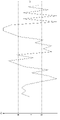
一方、実際に前記検流回路40が検知する交流電流は、図4又は図6に示すように、多少の乱れがある。本出願人は、ヒッティングの危険性が高くなると電流波形の乱れが大きくなり、ヒッティングが始まると電流波形の乱れが更に大きくなることを見いだした。電流波形の乱れは、基準となる波形と検出された波形とを比較して導き出された差分値ΔIにより定義される。なお、ここで言う差分値ΔIは、波形の面積の差分であってもよく、また、単純に振幅の差分であってもよい。何れの場合であっても、差分値ΔIの算出は、簡単なプログラムで極めて容易に行うことができる。そして、この現象を利用すれば、様々な物理量を測定するためのセンサ類を設けたり、前記ピストン23やディスプレイサー16の位置を算出したりすることなく、ヒッティングを抑制することができる。
On the other hand, the alternating current actually detected by the current detection circuit 40 has some disturbance as shown in FIG. 4 or FIG. The applicant has found that the current waveform becomes more turbulent as the risk of hitting increases, and that the current waveform becomes more turbulent when hitting begins. The disturbance of the current waveform is defined by the difference value ΔI derived by comparing the detected waveform with the reference waveform. Note that the difference value ΔI referred to here may be the difference in the areas of the waveforms, or may simply be the difference in the amplitudes. In any case, the difference value ΔI can be calculated very easily with a simple program. By utilizing this phenomenon, hitting can be suppressed without providing sensors for measuring various physical quantities or calculating the positions of the
なお、前記スターリング冷凍機1が安定動作する状態の電流波形は、運転強度や周囲の温度条件等により変化する。このため、予め基準波形を設定しておくのではなく、ほぼ安定動作している状態の電流波形を平均することで算出するのが望ましい。また、前記スターリング冷凍機1を作動させ続けることで周囲の温度条件等が変化したり、前記スターリング冷凍機1の運転強度を調節したりすると、前記検流回路40が検出する波形が変化する。従って、定期的に基準波形を算出するのが望ましい。
It should be noted that the current waveform when the
前記スターリング冷凍機1の動作がほぼ安定した状態で、前記制御回路41は、前記検流回路40が検知した交流電流のnサイクル分Cn1の波形を平均した1サイクル分の基準波形Ws1を算出する。なお、ここではn=5とする。そして、前記制御回路41は、次の5サイクルの交流電流Cn2の波形を一つずつ前記基準波形Ws1と比較し、その差分を算出する。同時に、前記制御回路41は、次の5サイクルの交流電流Cn2の波形を平均した1サイクル分の基準波形Ws2を算出する。そして、前記制御回路41は、更に次の5サイクルの交流電流Cn3の波形を一つずつ前記基準波形Ws2と比較し、その差分を算出する。同時に、前記制御回路41は、更に次の5サイクルの交流電流Cn3の波形を平均した1サイクル分の基準波形Ws3を算出する。これらを繰り返すことで、図5又は図7に示すような、電流の乱れを得ることができる。
In a state where the operation of the
図5に示すように、検出された電流波形の乱れ(差分値ΔI)が基準値+Bから-Bの範囲に収まっていれば、一応安定していると見なす。一方、図7に示すように、検出された電流波形の乱れ(差分値ΔI)が基準値+Bから-Bの範囲から逸脱すれば、その度合いに応じて前記制御回路41は前記インバータ回路39の出力を抑制する。 As shown in FIG. 5, if the detected current waveform disturbance (difference value ΔI) is within the range of the reference value +B to −B, it is assumed to be stable. On the other hand, as shown in FIG. 7, if the detected current waveform disturbance (difference value ΔI) deviates from the range of the reference value +B to −B, the control circuit 41 controls the inverter circuit 39 according to the degree of deviation. Suppress output.
以上のように本発明は、ケーシング2と、このケーシング2内に設けられるシリンダ15と、このシリンダ15内を往復動可能に設けられるピストン23と、このピストン23を往復動させるリニアモータ24と、前記ピストン23の往復動に伴って前記シリンダ15内を往復動するディスプレイサー16と、前記リニアモータ24の動作を制御する制御手段38とを有するフリーピストン型スターリング冷凍機1において、前記制御手段38が、所定の周波数の交流電流を作って前記リニアモータ24へ供給するインバータ回路39と、このインバータ回路39から出力される電流を検知する検流回路40と、この検流回路40が検知した電流の乱れに基づいて前記インバータ回路39からの出力を制御する制御回路41とを有することで、安価な構成で且つ単純な制御によりヒッティングを抑制することができるものである。
As described above, the present invention comprises a
また、本発明は、前記制御回路41が、前記インバータ回路39が出力した交流電流の1サイクル毎に、前記検流回路40が検出した検出波形と基準波形とを比較して差分値ΔIを算出し、この差分値ΔIを電流の乱れの判断基準とすることで、単純な演算でヒッティングを抑制することができるものである。 Further, according to the present invention, the control circuit 41 compares the detection waveform detected by the current detection circuit 40 with the reference waveform for each cycle of the alternating current output from the inverter circuit 39 to calculate the difference value ΔI. By using this difference value ΔI as a reference for current disturbance, it is possible to suppress hitting by a simple calculation.
また、本発明は、前記制御回路41が、nサイクル分の交流電流の検出波形を平均して1サイクル分の基準波形を算出することで、運転強度や周囲の温度等によって安定条件が異なる場合でも、同様に安定してヒッティングを抑制することができるものである。 In the present invention, the control circuit 41 calculates a reference waveform for one cycle by averaging detected waveforms of alternating current for n cycles. However, it can stably suppress hitting in the same way.
更に、本発明は、前記制御回路41が、算出された基準波形Ws1を算出元になったnサイクル分の交流電流Cn1に続く次のnサイクル分の交流電流Cn2の検出波形と比較すると共に、次のnサイクル分の交流電流Cn2の検出波形を平均して次の基準波形Ws2を算出することで、運転強度を調節したり周囲の温度等が変動したりすることによって安定条件が変動する場合でも、同様に安定してヒッティングを抑制することができるものである。 Furthermore, in the present invention, the control circuit 41 compares the calculated reference waveform Ws1 with the detected waveform of the alternating current Cn2 for the next n cycles following the alternating current Cn1 for n cycles, which is the basis of the calculation, and By calculating the next reference waveform Ws2 by averaging the detected waveforms of the AC current Cn2 for the next n cycles, when the stability condition fluctuates due to the adjustment of the driving intensity or fluctuations in the ambient temperature, etc. However, it can stably suppress hitting in the same way.
なお、本発明は以上の実施形態に限定されるものではなく、発明の要旨の範囲内で種々の変形実施が可能である。例えば、上記実施形態では、電流の乱れを判定する基準値が単一であるが、この基準値を複数段階にしてもよい。 It should be noted that the present invention is not limited to the above-described embodiments, and various modifications can be made within the scope of the gist of the invention. For example, in the above embodiment, a single reference value is used for determining current disturbance, but this reference value may be set in multiple stages.
1 フリーピストン型スターリング冷凍機
2 ケーシング
15 シリンダ
16 ディスプレイサー
23 ピストン
24 リニアモータ
38 制御手段
39 インバータ回路
40 検流回路
41 制御回路
Ws1~Ws7 基準波形
Cn1~Cn7 nサイクル分の検出波形
1 Free piston
Claims (2)
前記制御手段が、所定の周波数の交流電流を作って前記リニアモータへ供給するインバータ回路と、このインバータ回路から出力される電流を検知する検流回路と、この検流回路が検知した電流の波形面積又は振幅の乱れに基づいて前記インバータ回路からの出力を制御する制御回路とを有し、この制御回路が、nサイクル分の交流電流の検出波形を平均して1サイクル分の基準波形を算出するものであると共に、前記制御回路が、前記インバータ回路が出力した交流電流の1サイクル毎に、前記検流回路が検出した検出波形と基準波形とを比較して差分値を算出し、この差分値を電流の乱れの判断基準とするものであることを特徴とするフリーピストン型スターリング冷凍機。 a casing, a cylinder provided in the casing, a piston provided to reciprocate in the cylinder, a linear motor for reciprocating the piston, and a reciprocating motion in the cylinder accompanying the reciprocation of the piston. In a free piston Stirling refrigerator having a displacer and a control means for controlling the operation of the linear motor,
The control means includes an inverter circuit that generates an alternating current of a predetermined frequency and supplies it to the linear motor, a current detection circuit that detects the current output from the inverter circuit, and a waveform of the current detected by the current detection circuit. and a control circuit for controlling the output from the inverter circuit based on the disturbance of the area or amplitude , and the control circuit averages the detected alternating current waveforms for n cycles to calculate a reference waveform for one cycle. In addition, the control circuit compares the detected waveform detected by the galvanometer circuit with a reference waveform for each cycle of the alternating current output from the inverter circuit to calculate a difference value, and calculates the difference value. A free-piston type Stirling refrigerator, characterized in that a value is used as a criterion for judging current turbulence .
The control circuit compares the calculated reference waveform with the detected waveform of the alternating current for the next n cycles following the alternating current for n cycles from which the calculation is based, and detects the alternating current for the next n cycles. 2. A free-piston Stirling refrigerator according to claim 1 , wherein the next reference waveform is calculated by averaging the waveforms.
Priority Applications (3)
| Application Number | Priority Date | Filing Date | Title |
|---|---|---|---|
| JP2019232614A JP7143272B2 (en) | 2019-12-24 | 2019-12-24 | Free piston Stirling refrigerator |
| CN202011455147.1A CN113028673A (en) | 2019-12-24 | 2020-12-10 | Free piston type stirling cryocooler |
| US17/123,590 US11255581B2 (en) | 2019-12-24 | 2020-12-16 | Free piston Stirling refrigerator |
Applications Claiming Priority (1)
| Application Number | Priority Date | Filing Date | Title |
|---|---|---|---|
| JP2019232614A JP7143272B2 (en) | 2019-12-24 | 2019-12-24 | Free piston Stirling refrigerator |
Publications (2)
| Publication Number | Publication Date |
|---|---|
| JP2021101135A JP2021101135A (en) | 2021-07-08 |
| JP7143272B2 true JP7143272B2 (en) | 2022-09-28 |
Family
ID=76437959
Family Applications (1)
| Application Number | Title | Priority Date | Filing Date |
|---|---|---|---|
| JP2019232614A Active JP7143272B2 (en) | 2019-12-24 | 2019-12-24 | Free piston Stirling refrigerator |
Country Status (3)
| Country | Link |
|---|---|
| US (1) | US11255581B2 (en) |
| JP (1) | JP7143272B2 (en) |
| CN (1) | CN113028673A (en) |
Families Citing this family (1)
| Publication number | Priority date | Publication date | Assignee | Title |
|---|---|---|---|---|
| JP7143272B2 (en) * | 2019-12-24 | 2022-09-28 | ツインバード工業株式会社 | Free piston Stirling refrigerator |
Citations (3)
| Publication number | Priority date | Publication date | Assignee | Title |
|---|---|---|---|---|
| JP2002285958A (en) | 2001-03-28 | 2002-10-03 | Matsushita Refrig Co Ltd | Control valve of linear compressor |
| JP2003014322A (en) | 2001-06-29 | 2003-01-15 | Sharp Corp | Free piston type stirling refrigeration machine |
| JP2017169444A (en) | 2013-04-26 | 2017-09-21 | 富士電機株式会社 | Resonance suppressor |
Family Cites Families (58)
| Publication number | Priority date | Publication date | Assignee | Title |
|---|---|---|---|---|
| US3540287A (en) * | 1968-09-27 | 1970-11-17 | Us Navy | Boundary wave vector filter |
| JPS56139084A (en) * | 1980-03-31 | 1981-10-30 | Toshiba Corp | Control system of ac/dc converter |
| JPS6059979A (en) * | 1983-09-12 | 1985-04-06 | Fuji Electric Co Ltd | Synchronizing signal detecting circuit |
| EP0181511B1 (en) * | 1984-10-19 | 1990-08-22 | Kollmorgen Corporation | Servomotor control systems |
| US4678971A (en) * | 1985-01-14 | 1987-07-07 | Hitachi, Ltd. | Linear motor and control method thereof |
| US4862695A (en) * | 1986-11-05 | 1989-09-05 | Ice Cryogenic Engineering Ltd. | Split sterling cryogenic cooler |
| JPH0744875B2 (en) * | 1986-11-12 | 1995-05-15 | 株式会社東芝 | Electric motor drive |
| US4765150A (en) * | 1987-02-09 | 1988-08-23 | Margaux Controls, Inc. | Continuously variable capacity refrigeration system |
| USRE33620E (en) * | 1987-02-09 | 1991-06-25 | Margaux, Inc. | Continuously variable capacity refrigeration system |
| US4953109A (en) * | 1989-10-16 | 1990-08-28 | Design-Rite, Inc. | Automated trash compactor system |
| JPH0788985B2 (en) * | 1990-01-17 | 1995-09-27 | 三菱電機株式会社 | refrigerator |
| US5658132A (en) * | 1993-10-08 | 1997-08-19 | Sawafuji Electric Co., Ltd. | Power supply for vibrating compressors |
| JPH09260099A (en) * | 1996-03-15 | 1997-10-03 | Toshiba Corp | Particle accelerator power supply |
| US5929538A (en) * | 1997-06-27 | 1999-07-27 | Abacus Controls Inc. | Multimode power processor |
| US5893275A (en) * | 1997-09-04 | 1999-04-13 | In-X Corporation | Compact small volume liquid oxygen production system |
| AU766871B2 (en) * | 1997-11-24 | 2003-10-23 | Plug Power Inc. | Anti-islanding method and apparatus for distributed power generation |
| JP2003176788A (en) * | 2001-12-10 | 2003-06-27 | Matsushita Electric Ind Co Ltd | Drive unit for linear compressor |
| WO2003056257A1 (en) * | 2001-12-26 | 2003-07-10 | Sharp Kabushiki Kaisha | Stirling engine |
| KR100831793B1 (en) * | 2002-02-04 | 2008-05-28 | 엘지전자 주식회사 | Cooler |
| JP3540311B2 (en) * | 2002-05-31 | 2004-07-07 | 松下電器産業株式会社 | Motor drive control device |
| JP4126598B2 (en) * | 2002-09-12 | 2008-07-30 | 富士電機システムズ株式会社 | Operation control device for vibration compressor |
| JP4069420B2 (en) * | 2002-11-27 | 2008-04-02 | 富士電機システムズ株式会社 | Control device for power converter |
| EP1644629B1 (en) * | 2003-07-02 | 2008-09-10 | Tiax LLC | Free piston stirling engine control |
| KR100941422B1 (en) * | 2003-08-04 | 2010-02-10 | 삼성전자주식회사 | Linear compressor and control apparatus thereof |
| KR100539756B1 (en) * | 2003-12-01 | 2006-01-10 | 엘지전자 주식회사 | Stirling refrigerator |
| US7137259B2 (en) * | 2003-12-05 | 2006-11-21 | Superconductor Technologies Inc. | Cryocooler housing assembly apparatus and method |
| JP2005337551A (en) | 2004-05-25 | 2005-12-08 | Twinbird Corp | Free piston type stirling refrigerator and its control method |
| JP2006149110A (en) * | 2004-11-22 | 2006-06-08 | Sharp Corp | Alternating-current power generator and linear motor, stirling refrigerator, and linear compressor using the same |
| KR100761268B1 (en) * | 2006-01-06 | 2007-09-28 | 엘지전자 주식회사 | Driving control apparatus and method for reciprocating compressor |
| US20070256428A1 (en) * | 2006-05-05 | 2007-11-08 | Sunpower, Inc. | Vibration control of free piston machines through frequency adjustment |
| US8559197B2 (en) * | 2008-10-13 | 2013-10-15 | Infinia Corporation | Electrical control circuits for an energy converting apparatus |
| WO2010049976A1 (en) * | 2008-10-31 | 2010-05-06 | 三菱電機株式会社 | Power converter |
| ES2876279T3 (en) * | 2011-01-18 | 2021-11-12 | Daikin Ind Ltd | Power conversion apparatus |
| US8093858B1 (en) * | 2011-03-01 | 2012-01-10 | International Controls And Measurements Corp. | AC line voltage conditioner and controller |
| US20140091622A1 (en) * | 2011-04-15 | 2014-04-03 | Deka Products Limited Partnership | Modular Power Conversion System |
| US9068901B1 (en) * | 2012-04-25 | 2015-06-30 | Dynamic Solutions Llc | Multi-phase power amplifier |
| KR101573647B1 (en) * | 2012-05-11 | 2015-12-01 | 캐논 아네르바 가부시키가이샤 | Cold trap |
| US8896251B2 (en) * | 2012-10-29 | 2014-11-25 | Calnetix Technologies, Llc | Self-diagnostics within power electronics |
| US20140202172A1 (en) * | 2013-01-22 | 2014-07-24 | Sunpower, Inc. | Cold Finger For Cryocoolers |
| US9799779B2 (en) * | 2013-11-08 | 2017-10-24 | The Board Of Trustees Of The University Of Illinois | Systems and methods for photovoltaic string protection |
| US20160181809A1 (en) * | 2014-12-17 | 2016-06-23 | National Chung Shan Institute Of Science And Technology | Grid system conducive to enhancement of power supply performance |
| JP2016161140A (en) * | 2015-02-26 | 2016-09-05 | ツインバード工業株式会社 | Stirling refrigerator |
| JP6414513B2 (en) * | 2015-06-05 | 2018-10-31 | アイシン・エィ・ダブリュ株式会社 | Rotating electrical machine control device |
| US20170051590A1 (en) * | 2015-08-20 | 2017-02-23 | Baker Hughes Incorporated | Systems and Methods for Determining Forces on a Linear Permanent Magnet Motor Using Instantaneous Current Vectors |
| JP6434647B2 (en) * | 2015-11-02 | 2018-12-05 | 三菱電機株式会社 | Motor drive, vacuum cleaner and hand dryer |
| KR102331103B1 (en) * | 2015-11-27 | 2021-11-26 | 엘지전자 주식회사 | Compressor and method for controlling compressor |
| KR20170062303A (en) * | 2015-11-27 | 2017-06-07 | 엘지전자 주식회사 | Compressor and method for controlling compressor |
| US10090788B2 (en) * | 2016-03-03 | 2018-10-02 | Robert Bosch Gmbh | Optimal torque ripple reduction through current shaping |
| IL244428B (en) * | 2016-03-03 | 2020-08-31 | Semi Conductor Devices An Elbit Systems Rafael Partnership | Low vibration cryogenic refrigerator |
| US20210157312A1 (en) * | 2016-05-09 | 2021-05-27 | Strong Force Iot Portfolio 2016, Llc | Intelligent vibration digital twin systems and methods for industrial environments |
| US20200225655A1 (en) * | 2016-05-09 | 2020-07-16 | Strong Force Iot Portfolio 2016, Llc | Methods, systems, kits and apparatuses for monitoring and managing industrial settings in an industrial internet of things data collection environment |
| KR20180085316A (en) * | 2017-01-18 | 2018-07-26 | 엘지전자 주식회사 | Apparatus for controlling linear compressor |
| WO2019075122A1 (en) * | 2017-10-11 | 2019-04-18 | Flir Commercial Systems, Inc. | Cryocooler controller systems and methods |
| US11128248B2 (en) * | 2018-02-21 | 2021-09-21 | The Universitv of Akron | DC input current ripple reduction in SRM drive for high volumetric power density applications |
| WO2020051557A1 (en) * | 2018-09-06 | 2020-03-12 | Cornell University | High power density power converter and uninterruptible power supply circuit and methods |
| EP3647797A1 (en) * | 2018-11-05 | 2020-05-06 | ABB Schweiz AG | An inverter comprising means for detecting arcing faults in the dc section of a photovoltaic plant |
| US11209192B2 (en) * | 2019-07-29 | 2021-12-28 | Cryo Tech Ltd. | Cryogenic Stirling refrigerator with a pneumatic expander |
| JP7143272B2 (en) * | 2019-12-24 | 2022-09-28 | ツインバード工業株式会社 | Free piston Stirling refrigerator |
-
2019
- 2019-12-24 JP JP2019232614A patent/JP7143272B2/en active Active
-
2020
- 2020-12-10 CN CN202011455147.1A patent/CN113028673A/en active Pending
- 2020-12-16 US US17/123,590 patent/US11255581B2/en active Active
Patent Citations (3)
| Publication number | Priority date | Publication date | Assignee | Title |
|---|---|---|---|---|
| JP2002285958A (en) | 2001-03-28 | 2002-10-03 | Matsushita Refrig Co Ltd | Control valve of linear compressor |
| JP2003014322A (en) | 2001-06-29 | 2003-01-15 | Sharp Corp | Free piston type stirling refrigeration machine |
| JP2017169444A (en) | 2013-04-26 | 2017-09-21 | 富士電機株式会社 | Resonance suppressor |
Also Published As
| Publication number | Publication date |
|---|---|
| JP2021101135A (en) | 2021-07-08 |
| US20210190387A1 (en) | 2021-06-24 |
| CN113028673A (en) | 2021-06-25 |
| US11255581B2 (en) | 2022-02-22 |
Similar Documents
| Publication | Publication Date | Title |
|---|---|---|
| JP3511018B2 (en) | Linear compressor drive | |
| JP6309582B2 (en) | Vibration welding system | |
| JP4580268B2 (en) | Free piston position measuring device and free piston control device | |
| KR100474330B1 (en) | Driving comtrol apparatus of reciprocating compressor for refrigerator | |
| KR20030091716A (en) | Driving apparatus of a linear motor | |
| WO2003056257A1 (en) | Stirling engine | |
| JP7143272B2 (en) | Free piston Stirling refrigerator | |
| AU2004269283B2 (en) | Linear motor controller improvements | |
| WO2018070339A1 (en) | Linear motor control device and compressor equipped with same | |
| JP7174490B2 (en) | Free piston Stirling refrigerator | |
| JP4703243B2 (en) | Linear motor control system and Stirling refrigeration system | |
| JP2007298219A (en) | Stirling refrigerating machine | |
| JPH11336661A (en) | Control unit for liner motor driven reciprocating mechanism | |
| JP2008196320A (en) | Control method of linear compressor | |
| JP2009017755A (en) | Linear-motor controller and stirling engine | |
| JP6833881B2 (en) | Reciprocating motion engine | |
| JP2004522063A (en) | Control device and method for reciprocating compressor | |
| JP2008005633A (en) | Linear motor control system, sterling refrigerator control system using the same, and linear compressor control system | |
| JP2005337551A (en) | Free piston type stirling refrigerator and its control method | |
| WO2006035540A1 (en) | Ac power generator and stirling refrigerator employing the same | |
| JP2005009353A (en) | Stirling engine | |
| JP3881998B2 (en) | Stirling refrigeration system |
Legal Events
| Date | Code | Title | Description |
|---|---|---|---|
| A521 | Request for written amendment filed |
Free format text: JAPANESE INTERMEDIATE CODE: A523 Effective date: 20191226 |
|
| A621 | Written request for application examination |
Free format text: JAPANESE INTERMEDIATE CODE: A621 Effective date: 20210617 |
|
| A977 | Report on retrieval |
Free format text: JAPANESE INTERMEDIATE CODE: A971007 Effective date: 20220414 |
|
| A131 | Notification of reasons for refusal |
Free format text: JAPANESE INTERMEDIATE CODE: A131 Effective date: 20220426 |
|
| A521 | Request for written amendment filed |
Free format text: JAPANESE INTERMEDIATE CODE: A523 Effective date: 20220616 |
|
| TRDD | Decision of grant or rejection written | ||
| A01 | Written decision to grant a patent or to grant a registration (utility model) |
Free format text: JAPANESE INTERMEDIATE CODE: A01 Effective date: 20220909 |
|
| A61 | First payment of annual fees (during grant procedure) |
Free format text: JAPANESE INTERMEDIATE CODE: A61 Effective date: 20220914 |
|
| R150 | Certificate of patent or registration of utility model |
Ref document number: 7143272 Country of ref document: JP Free format text: JAPANESE INTERMEDIATE CODE: R150 |
|
| S533 | Written request for registration of change of name |
Free format text: JAPANESE INTERMEDIATE CODE: R313533 |
|
| R350 | Written notification of registration of transfer |
Free format text: JAPANESE INTERMEDIATE CODE: R350 |