JP7141403B2 - Laser scanner with real-time online self-motion estimation - Google Patents
Laser scanner with real-time online self-motion estimation Download PDFInfo
- Publication number
- JP7141403B2 JP7141403B2 JP2019540661A JP2019540661A JP7141403B2 JP 7141403 B2 JP7141403 B2 JP 7141403B2 JP 2019540661 A JP2019540661 A JP 2019540661A JP 2019540661 A JP2019540661 A JP 2019540661A JP 7141403 B2 JP7141403 B2 JP 7141403B2
- Authority
- JP
- Japan
- Prior art keywords
- data
- imu
- frequency
- scan
- mapping system
- Prior art date
- Legal status (The legal status is an assumption and is not a legal conclusion. Google has not performed a legal analysis and makes no representation as to the accuracy of the status listed.)
- Active
Links
Images


Classifications
-
- G—PHYSICS
- G01—MEASURING; TESTING
- G01S—RADIO DIRECTION-FINDING; RADIO NAVIGATION; DETERMINING DISTANCE OR VELOCITY BY USE OF RADIO WAVES; LOCATING OR PRESENCE-DETECTING BY USE OF THE REFLECTION OR RERADIATION OF RADIO WAVES; ANALOGOUS ARRANGEMENTS USING OTHER WAVES
- G01S17/00—Systems using the reflection or reradiation of electromagnetic waves other than radio waves, e.g. lidar systems
- G01S17/88—Lidar systems specially adapted for specific applications
- G01S17/89—Lidar systems specially adapted for specific applications for mapping or imaging
-
- G—PHYSICS
- G01—MEASURING; TESTING
- G01C—MEASURING DISTANCES, LEVELS OR BEARINGS; SURVEYING; NAVIGATION; GYROSCOPIC INSTRUMENTS; PHOTOGRAMMETRY OR VIDEOGRAMMETRY
- G01C11/00—Photogrammetry or videogrammetry, e.g. stereogrammetry; Photographic surveying
- G01C11/02—Picture taking arrangements specially adapted for photogrammetry or photographic surveying, e.g. controlling overlapping of pictures
-
- G—PHYSICS
- G01—MEASURING; TESTING
- G01C—MEASURING DISTANCES, LEVELS OR BEARINGS; SURVEYING; NAVIGATION; GYROSCOPIC INSTRUMENTS; PHOTOGRAMMETRY OR VIDEOGRAMMETRY
- G01C21/00—Navigation; Navigational instruments not provided for in groups G01C1/00 - G01C19/00
- G01C21/10—Navigation; Navigational instruments not provided for in groups G01C1/00 - G01C19/00 by using measurements of speed or acceleration
- G01C21/12—Navigation; Navigational instruments not provided for in groups G01C1/00 - G01C19/00 by using measurements of speed or acceleration executed aboard the object being navigated; Dead reckoning
- G01C21/16—Navigation; Navigational instruments not provided for in groups G01C1/00 - G01C19/00 by using measurements of speed or acceleration executed aboard the object being navigated; Dead reckoning by integrating acceleration or speed, i.e. inertial navigation
- G01C21/165—Navigation; Navigational instruments not provided for in groups G01C1/00 - G01C19/00 by using measurements of speed or acceleration executed aboard the object being navigated; Dead reckoning by integrating acceleration or speed, i.e. inertial navigation combined with non-inertial navigation instruments
- G01C21/1656—Navigation; Navigational instruments not provided for in groups G01C1/00 - G01C19/00 by using measurements of speed or acceleration executed aboard the object being navigated; Dead reckoning by integrating acceleration or speed, i.e. inertial navigation combined with non-inertial navigation instruments with passive imaging devices, e.g. cameras
-
- G—PHYSICS
- G01—MEASURING; TESTING
- G01S—RADIO DIRECTION-FINDING; RADIO NAVIGATION; DETERMINING DISTANCE OR VELOCITY BY USE OF RADIO WAVES; LOCATING OR PRESENCE-DETECTING BY USE OF THE REFLECTION OR RERADIATION OF RADIO WAVES; ANALOGOUS ARRANGEMENTS USING OTHER WAVES
- G01S17/00—Systems using the reflection or reradiation of electromagnetic waves other than radio waves, e.g. lidar systems
- G01S17/02—Systems using the reflection of electromagnetic waves other than radio waves
- G01S17/06—Systems determining position data of a target
- G01S17/42—Simultaneous measurement of distance and other co-ordinates
-
- G—PHYSICS
- G01—MEASURING; TESTING
- G01S—RADIO DIRECTION-FINDING; RADIO NAVIGATION; DETERMINING DISTANCE OR VELOCITY BY USE OF RADIO WAVES; LOCATING OR PRESENCE-DETECTING BY USE OF THE REFLECTION OR RERADIATION OF RADIO WAVES; ANALOGOUS ARRANGEMENTS USING OTHER WAVES
- G01S17/00—Systems using the reflection or reradiation of electromagnetic waves other than radio waves, e.g. lidar systems
- G01S17/86—Combinations of lidar systems with systems other than lidar, radar or sonar, e.g. with direction finders
-
- G—PHYSICS
- G01—MEASURING; TESTING
- G01S—RADIO DIRECTION-FINDING; RADIO NAVIGATION; DETERMINING DISTANCE OR VELOCITY BY USE OF RADIO WAVES; LOCATING OR PRESENCE-DETECTING BY USE OF THE REFLECTION OR RERADIATION OF RADIO WAVES; ANALOGOUS ARRANGEMENTS USING OTHER WAVES
- G01S7/00—Details of systems according to groups G01S13/00, G01S15/00, G01S17/00
- G01S7/48—Details of systems according to groups G01S13/00, G01S15/00, G01S17/00 of systems according to group G01S17/00
- G01S7/4808—Evaluating distance, position or velocity data
-
- G—PHYSICS
- G01—MEASURING; TESTING
- G01S—RADIO DIRECTION-FINDING; RADIO NAVIGATION; DETERMINING DISTANCE OR VELOCITY BY USE OF RADIO WAVES; LOCATING OR PRESENCE-DETECTING BY USE OF THE REFLECTION OR RERADIATION OF RADIO WAVES; ANALOGOUS ARRANGEMENTS USING OTHER WAVES
- G01S7/00—Details of systems according to groups G01S13/00, G01S15/00, G01S17/00
- G01S7/48—Details of systems according to groups G01S13/00, G01S15/00, G01S17/00 of systems according to group G01S17/00
- G01S7/481—Constructional features, e.g. arrangements of optical elements
- G01S7/4811—Constructional features, e.g. arrangements of optical elements common to transmitter and receiver
- G01S7/4813—Housing arrangements
Landscapes
- Engineering & Computer Science (AREA)
- Radar, Positioning & Navigation (AREA)
- Remote Sensing (AREA)
- Physics & Mathematics (AREA)
- General Physics & Mathematics (AREA)
- Computer Networks & Wireless Communication (AREA)
- Electromagnetism (AREA)
- Automation & Control Theory (AREA)
- Multimedia (AREA)
- Navigation (AREA)
- Control Of Position, Course, Altitude, Or Attitude Of Moving Bodies (AREA)
- Optical Radar Systems And Details Thereof (AREA)
- Image Analysis (AREA)
Description
本発明は、モバイルマッピングシステムに関する。 The present invention relates to mobile mapping systems.
(優先権の主張)
この出願は、2017年10月10日出願の「実時間オンライン自己運動推定を備えたレーザスキャナ(LASER SCANNER WITH REAL-TIME,ONLINE EGO-MOTION ESTIMATION)」という名称のPCT出願番号PCT/US2017/055938(代理人整理番号KRTA-0008-WO)に対する優先権を主張し、かつその一部継続出願である。
(Priority claim)
This application is filed on October 10, 2017, entitled "LASER SCANNER WITH REAL-TIME, ONLINE EGO-MOTION ESTIMATION," PCT Application No. PCT/US2017/055938. (Attorney Docket No. KRTA-0008-WO) and is a continuation-in-part application thereof.
PCT出願番号PCT/US2017/055938は、2017年3月7日出願の「実時間オンライン自己運動推定を備えたレーザスキャナ(LASER SCANNER WITH REAL-TIME,ONLINE EGO-MOTION ESTIMATION)」という名称のPCT出願番号PCT/US2017/021120(代理人整理番号KRTA-0005-WO)に対する優先権を主張し、かつその一部継続出願である。この出願は、同様に、PCT出願番号PCT/US2017/021120に対する優先権を主張するものである。PCT出願番号PCT/US2017/055938は、2016年10月11日出願の「実時間オンライン自己運動推定を備えたレーザスキャナ(LASER SCANNER WITH REAL-TIME,ONLINE EGO-MOTION ESTIMATION)」という名称の米国特許仮出願第62/406,910号(代理人整理番号KRTA-0002-P02)に対する優先権を更に主張するものである。 PCT Application No. PCT/US2017/055938 is a PCT application entitled "LASER SCANNER WITH REAL-TIME, ONLINE EGO-MOTION ESTIMATION" filed March 7, 2017 No. PCT/US2017/021120 (Attorney Docket No. KRTA-0005-WO) and is a continuation-in-part application thereof. This application also claims priority to PCT Application No. PCT/US2017/021120. PCT Application No. PCT/US2017/055938, entitled "LASER SCANNER WITH REAL-TIME, ONLINE EGO-MOTION ESTIMATION", filed Oct. 11, 2016 It further claims priority to Provisional Application No. 62/406,910 (Attorney Docket No. KRTA-0002-P02).
PCT出願番号PCT/US2017/021120は、2016年3月11日出願の「実時間オンライン自己運動推定を備えたレーザスキャナ(LASER SCANNER WITH REAL-TIME,ONLINE EGO-MOTION ESTIMATION)」という名称の米国特許仮出願第62/307,061号(代理人整理番号KRTA-0001-P01)の利益を主張するものである。 PCT Application No. PCT/US2017/021120, entitled "LASER SCANNER WITH REAL-TIME, ONLINE EGO-MOTION ESTIMATION", filed March 11, 2016 It claims the benefit of Provisional Application No. 62/307,061 (Attorney Docket No. KRTA-0001-P01).
この出願は、2017年1月27日出願の「ライダー及び視覚ベースの自己運動推定及びマッピング(LIDAR AND VISION-BASED EGO-MOTION ESTIMATION AND MAPPING)」という名称の米国特許仮出願第62/451,294号(代理人整理番号KRTA-0004-P01)に対する優先権を更に主張するものである。 No. 62/451,294, entitled "LIDAR AND VISION-BASED EGO-MOTION ESTIMATION AND MAPPING," filed Jan. 27, 2017. (Attorney Docket No. KRTA-0004-P01).
(関連出願の相互参照)
PCT/US2017/055938、PCT/US2017/021120、及び米国特許仮出願第62/406,910号明細書、第62/307,061号明細書、及び第62/451,294号明細書の開示は、それらの全体が全ての目的に対して引用によって本明細書に組み込まれている。
(Cross reference to related applications)
The disclosures of PCT/US2017/055938, PCT/US2017/021120, and US Provisional Patent Application Nos. 62/406,910, 62/307,061, and 62/451,294 , which are incorporated herein by reference in their entireties for all purposes.
自律移動デバイスは、それがそこで作動する地形に関する情報を必要とする場合がある。そのようなデバイスは、地形を提示する予め定められたマップ及びそこに見出される場合があるあらゆる障害物のいずれかに依存する場合がある。これに代えて、デバイスは、実時間データを提供する1又は2以上のセンサを有するコンピュータベースのマッピングシステムを含む静止又は運動中である間にその地形をマッピングする機能を有する場合がある。モバイルコンピュータベースマッピングシステムは、その経時的な位置の変化を推定する(オドメータ)及び/又は3次元空間の点クラウドのような3次元マップ表現を発生させることができる。 An autonomous mobile device may need information about the terrain on which it operates. Such devices may rely either on a predetermined map presenting the terrain and any obstacles that may be found therein. Alternatively, the device may have the ability to map its terrain while stationary or in motion, including a computer-based mapping system having one or more sensors that provide real-time data. A mobile computer-based mapping system can estimate its change in position over time (odometer) and/or generate a 3D map representation, such as a point cloud of a 3D space.
例示的マッピングシステムは、マップをそこから構築することができるデータを提供する様々なセンサを含むことができる。一部のマッピングシステムは、1つのそのようなセンサとして立体カメラシステムを用いる場合がある。これらのシステムは、運動推定のスケールを決定するための基準としての2つのカメラ間のベースラインから利益を得ている。双眼システムは、単眼システムよりも好ましく、その理由は、単眼システムは、追加のセンサからデータを受信する又はデバイスの運動に関する仮定を行うことなしには画像のスケールを決定することができない場合があるからである。近年では、研究分野においてRGB-Dカメラが一般的になってきている。そのようなカメラは、個々のピクセルに関連付けられた深度情報を提供することができ、従って、スケールを決定するのを助けることができる。しかし、RGB-Dカメラを含む一部の方法は、深度情報のカバレージを有する画像区域のみを用いることができ、その結果、特に深度を疎に取得することのみができる開放空間では、大きい画像区域が無駄になる場合がある。 An exemplary mapping system can include various sensors that provide data from which maps can be constructed. Some mapping systems may use a stereoscopic camera system as one such sensor. These systems benefit from the baseline between the two cameras as a reference for determining the scale of motion estimation. Binocular systems are preferred over monocular systems because monocular systems may not be able to determine the scale of the image without receiving data from additional sensors or making assumptions about device motion. It is from. In recent years, RGB-D cameras have become popular in the research field. Such cameras can provide depth information associated with individual pixels, thus helping determine scale. However, some methods involving RGB-D cameras can only use image areas with depth information coverage, resulting in large image areas, especially in open spaces where depth can only be acquired sparsely. may be wasted.
マッピングシステムの他の例では、IMUは、スケール制約をIMU加速から与えることができるように1又は2以上のカメラに結合される場合がある。一部の例では、単眼カメラは、カルマンフィルタを用いてIMUに緊密に又は緩く結合することができる。他のマッピングシステムは、モバイルシステムの運動を解くために最適化方法を用いる場合がある。 In other examples of mapping systems, an IMU may be coupled to one or more cameras such that scale constraints can be provided from IMU acceleration. In some examples, a monocular camera can be tightly or loosely coupled to an IMU using a Kalman filter. Other mapping systems may use optimization methods to solve for mobile system motion.
マッピングシステムの代替例は、運動推定のためのレーザスキャナの使用を含むことができる。しかし、レーザの走査速度からそのようなデータの使用の難しさが生じる場合がある。システムが移動している間に、固定位置レーザスキャナとは異なり、レーザ点は、スキャナの相対移動による影響を受ける。従って、この移動の影響は、到達するレーザ点が異なる時間にシステムに到達する要因である場合がある。その結果、走査速度がマッピングシステムの運動に対して低速である時に、レーザの外部運動に起因して走査歪みが存在する場合がある。この運動の効果は、レーザ自体によって補償することができるが、この補償は、必要とされる補正を与えるために独立運動モデルを必要とする場合がある。一例として、運動は、一定速度として又はガウス過程としてモデル化することができる。一部の例では、IMUは、運動モデルを与えることができる。そのような方法は、センサ運動を推定するためにレーザ点クラウドによって形成された空間-時間パッチを整合させ、オフラインバッチ最適化でIMUバイアスを補正する。 Alternative mapping systems can include the use of laser scanners for motion estimation. However, difficulties in using such data may arise from the scanning speed of the laser. While the system is moving, unlike fixed position laser scanners, the laser spot is affected by the relative movement of the scanner. This movement effect may therefore be a factor in the arriving laser spots arriving at the system at different times. As a result, there may be scan distortion due to external motion of the laser when the scan speed is slow relative to the motion of the mapping system. This motion effect can be compensated for by the laser itself, but this compensation may require an independent motion model to provide the required correction. As an example, motion can be modeled as a constant velocity or as a Gaussian process. In some examples, the IMU can provide a motion model. Such methods align space-time patches formed by laser point clouds to estimate sensor motion and correct for IMU bias with offline batch optimization.
運動歪みの同様の問題は、ローリングシャッターカメラの使用時に見出される場合がある。特に、画像ピクセルは、経時的に連続的に受信される場合があり、カメラの外来的な運動によって引き起こされる画像歪みをもたらす。一部の例では、視覚オドメトリ方法は、ピクセル読み出し時間を所与として、IMUを用いてローリングシャッター効果を補償することができる。 A similar problem of motion distortion may be found when using rolling shutter cameras. In particular, image pixels may be received continuously over time, resulting in image distortion caused by extrinsic motion of the camera. In some examples, the visual odometry method can use an IMU to compensate for the rolling shutter effect given the pixel readout time.
一部の例では、モバイルマッピングデバイスの位置を決定するためにGPS/INS技術を用いることができる。しかし、高精度GPS/INSソリューションは、用途がGPS拒絶、軽量、又はコスト重視である時に実際的でない場合がある。正確なGPSマッピングは、GPS受信器と少なくとも4つのGPS衛星(5つが好ましいと考えられるが)間に見通し通信を必要とすることが認識されている。一部の環境では、例えば、高架道路及び他の障害物を含む場合ある都市環境では、4つの衛星から歪みのない信号を受信することが困難である場合がある。 In some examples, GPS/INS technology can be used to determine the location of the mobile mapping device. However, high accuracy GPS/INS solutions may not be practical when the application is GPS rejection, lightweight, or cost sensitive. It is recognized that accurate GPS mapping requires line-of-sight communication between the GPS receiver and at least four GPS satellites (although five are considered preferred). In some environments, for example, an urban environment that may include flyovers and other obstacles, it may be difficult to receive undistorted signals from four satellites.
すなわち、特にマッピングデバイスが運動中である間に自律マッピングデバイスを取り囲む地形のロバストマップを発生させるために光学デバイスからのデータを他の運動測定デバイスと融合することに関連付けられたいくつかの技術的課題が存在することが認められるであろう。以下で開示するのは、光学マッピング情報を取得し、かつ歪みが低減したロバストマップを生成することができるマッピングデバイスの方法及びシステムである。 That is, some technical techniques associated with fusing data from optical devices with other motion-measuring devices to generate a robust map of the terrain surrounding an autonomous mapping device, especially while the mapping device is in motion. It will be appreciated that challenges exist. Disclosed below are methods and systems for mapping devices that can acquire optical mapping information and generate robust maps with reduced distortion.
例示的かつ非限定的実施形態により、方法は、IMUデバイスからデータを第1の計算モジュールで第1の周波数で受信して受信IMUデータに少なくとも部分的に基づいてモバイルマッピングシステムの第1の推定位置を計算する段階と、第1の推定位置及び視覚-慣性データを第2の計算モジュールで第2の周波数で受信して第1の推定位置及び視覚-慣性データに少なくとも部分的に基づいてモバイルマッピングシステムの第2の推定位置を計算する段階と、第2の推定位置及びレーザ走査データを第3の計算モジュールで第3の周波数で受信して第2の推定位置及びレーザ走査データに少なくとも部分的に基づいてモバイルマッピングシステムの第3の推定位置を計算する段階とを含む。 According to an exemplary and non-limiting embodiment, a method receives data from an IMU device at a first computing module at a first frequency to generate a first estimate for a mobile mapping system based at least in part on the received IMU data. calculating a position; and receiving a first position estimate and visual-inertial data at a second calculation module at a second frequency to operate the mobile based at least in part on the first position estimate and visual-inertial data. calculating a second position estimate of the mapping system; receiving the second position estimate and the laser scan data at a third calculation module at a third frequency to generate at least a portion of the second position estimate and the laser scan data; and calculating a third estimated position of the mobile mapping system based on the target.
別の例示的かつ非限定的実施形態により、モバイルマッピングシステムは、IMUデバイスから第1の周波数でデータを受信して受信IMUデータに少なくとも部分的に基づいてモバイルマッピングシステムの第1の推定位置を計算するようになった第1の計算モジュールと、第1の推定位置及び視覚-慣性データを第2の周波数で受信して第1の推定位置及び視覚-慣性データに少なくとも部分的に基づいてモバイルマッピングシステムの第2の推定位置を計算するようになった第2の計算モジュールと、第2の推定位置及びレーザ走査データを第3の周波数で受信して第2の推定位置及びレーザ走査データに少なくとも部分的に基づいてモバイルマッピングシステムの第3の推定位置を計算するようになった第3の計算モジュールとを含む。 According to another exemplary and non-limiting embodiment, a mobile mapping system receives data on a first frequency from an IMU device and determines a first estimated position of the mobile mapping system based at least in part on the received IMU data. a first computation module adapted to compute and receive a first estimated position and visual-inertial data at a second frequency and based at least in part on the first estimated position and visual-inertial data; a second computation module adapted to compute a second position estimate of the mapping system; and receiving the second position estimate and laser scan data at a third frequency to convert the second position estimate and laser scan data. and a third calculation module adapted to calculate a third estimated position of the mobile mapping system based at least in part.
一全般的態様では、本発明は、経時的な位置変化を推定する(オドメータ)及び/又は点クラウドのような3次元空間の3次元マップ表現を発生させるモバイルコンピュータベースのマッピングシステムに関する。マッピングシステムは、以下に限定されるものではないが、慣性測定ユニット(IMU)、カメラ、及び/又は3Dレーザスキャナを含む複数のセンサを含むことができる。マッピングシステムはまた、経時的なシステムの位置変化を推定するために及び/又は周囲環境のマップ表現を発生させるために複数のセンサと通信状態にあり、これらのセンサからの出力を処理するように構成された少なくとも1つのプロセッサを有するコンピュータシステムを含むことができる。マッピングシステムは、高周波数低待ち時間オンライン実時間自己運動推定を高密度で正確な3Dマップ位置合わせと共に可能にすることができる。本発明の開示の実施形態は、同時定位及びマッピング(SLAM)システムを含むことができる。SLAMシステムは、GPSに依存せず、実時間で同時の定位及びマッピングを可能にする多次元(例えば3D)レーザ走査及び距離測定システムを含むことができる。SLAMシステムは、環境内にある物体からのレーザ走査の反射から生じる非常に正確な点クラウドに関するデータを発生させて管理することができる。点クラウド内の点のうちのいずれの移動も、SLAMシステムが環境を通って進む時にシステムの場所及び方位の精確な理解を維持することができるように、点クラウド内の点を場所に対する基準点として用いて経時的に正確に追跡される。 In one general aspect, the present invention relates to a mobile computer-based mapping system that estimates position change over time (odometer) and/or generates a 3D map representation of a 3D space, such as a point cloud. A mapping system may include multiple sensors including, but not limited to, an inertial measurement unit (IMU), a camera, and/or a 3D laser scanner. The mapping system is also in communication with and processes the outputs from the sensors to estimate changes in position of the system over time and/or to generate a map representation of the surrounding environment. A computer system having at least one processor configured may be included. The mapping system can enable high-frequency low-latency online real-time self-motion estimation with dense and accurate 3D map registration. Embodiments of the present disclosure may include simultaneous localization and mapping (SLAM) systems. The SLAM system is GPS-independent and can include a multi-dimensional (eg, 3D) laser scanning and ranging system that enables simultaneous localization and mapping in real-time. SLAM systems can generate and manage data on highly accurate point clouds resulting from reflections of laser scanning from objects in the environment. Movement of any of the points in the point cloud aligns the points in the point cloud with respect to location so that the SLAM system can maintain an accurate understanding of the system's location and orientation as it navigates through the environment. is accurately tracked over time using .
一実施形態では、モバイルマッピングシステムの位置及び運動の解像度は、一連の粗から細への更新において順番に精緻化することができる。非限定例では、モバイルマッピングシステムの位置及び運動を高速更新速度を有する粗な解像度からより低速の更新速度を有する微細解像度へと更新するために個別の計算モジュールを用いることができる。例えば、高い更新速度でマッピングシステムの運動又は位置を予測するためのデータをIMUデバイスが第1の計算モジュールに提供することができる。低い更新速度でマッピングシステムの運動又は位置の解像度を改善するためのデータを視覚-慣性オドメトリシステムが第2の計算モジュールに提供することができる。これに加えて、更に低い更新速度で運動推定値を更に精緻化し、マップを位置合わせするためのデータをレーザスキャナが第3の計算走査整合モジュールに提供することができる。一非限定例では、位置及び/又は運動の微細解像度データを処理するように構成された計算モジュールからのデータは、位置及び/又は運動の粗な解像度データを処理するように構成された計算モジュールにフィードバックすることができる。別の非限定例では、計算モジュールは、センサソーシング不良、不正データ、不完全データ、又は非存在データに関連付けられた計算モジュールを自動的に迂回することによってセンサ劣化問題に対処する耐故障性を組み込むことができる。従って、マッピングシステムは、非常に動的な運動の存在下で更に暗く凹凸及び構造のない環境内で作動することができる。 In one embodiment, the position and motion resolution of the mobile mapping system can be refined sequentially in a series of coarse-to-fine updates. In a non-limiting example, a separate computational module can be used to update the position and motion of the mobile mapping system from coarse resolution with a fast update rate to fine resolution with a slower update rate. For example, an IMU device may provide data to the first computational module for predicting the motion or position of the mapping system at a high update rate. A visual-inertial odometry system can provide data to the second computational module to improve the motion or positional resolution of the mapping system at low update rates. In addition, the laser scanner can provide data to the third computational scan alignment module to further refine the motion estimate and align the maps at a lower update rate. In one non-limiting example, the data from the computation module configured to process fine resolution position and/or motion data is the data from the computation module configured to process coarse resolution position and/or motion data. can give feedback to In another non-limiting example, the computing module incorporates fault tolerance to address sensor degradation issues by automatically bypassing computing modules associated with sensor sourcing failures, incorrect data, incomplete data, or non-existent data. be able to. Thus, the mapping system can operate in the presence of highly dynamic motion and in a darker, uneven and structure-free environment.
大部分がオフラインバッチシステムである既存のマップ発生技術とは対照的に、本明細書に開示するマッピングシステムは実時間で作動し、運動中である間にマップを発生させることができる。この機能は2つの実用的な利点をもたらす。第1に、ユーザは、三脚又は他の非定常マウント上に固定されるスキャナに限定されない。代わりに、本明細書に開示するマッピングシステムは、モバイルデバイスに関連付け、それによって実時間でマッピングすることができる環境範囲を拡大することができる。第2に、実時間特徴は、データが収集される間に現在のマップ区域に関するフィードバックをユーザに与えることができる。オンライン発生マップは、自律的なナビゲーション及び障害物回避のためのロボット又は他のデバイスを助けることもできる。一部の非限定的実施形態では、そのようなナビゲーション機能は、マッピングシステム自体の中に組み込むことができる。代替非限定的実施形態では、マップデータは、外部ソースマップを必要とする可能性があるナビゲーション機能を有する追加ロボットに提供することができる。 In contrast to existing map generation techniques, which are mostly offline batch systems, the mapping system disclosed herein operates in real-time and can generate maps while in motion. This feature provides two practical advantages. First, users are not limited to scanners fixed on tripods or other non-stationary mounts. Instead, the mapping system disclosed herein can be associated with mobile devices, thereby expanding the range of environments that can be mapped in real time. Second, real-time features can give users feedback about the current map area while data is being collected. Online generated maps can also assist robots or other devices for autonomous navigation and obstacle avoidance. In some non-limiting embodiments, such navigation functionality can be built into the mapping system itself. In an alternate non-limiting embodiment, map data can be provided to additional robots with navigation capabilities that may require externally sourced maps.
センサに対して、3Dモデル化、シーンマッピング、及び環境推測のようないくつかの潜在的な用途が存在する。マッピングシステムは、点クラウドを更に別の処理のための入力として取得する他のアルゴリズムに対して点クラウドマップを提供することができる。更に、マッピングシステムは、屋内と屋外の両方で機能することができる。そのような実施形態は、外部照明を必要とせず、暗所で作動することができる。カメラを有する実施形態は、外部照明が必要とされる可能性があるが、急激な運動に対処することができ、カメラからの画像でレーザ点クラウドを着色することができる。SLAMシステムは、ユーザが環境を通って移動する、例えば、歩く、サイクリングする、運転する、飛行する、更にこれらの組み合わせを行う時に点クラウドを実時間で構築して維持することができる。マップは、マッピング器が環境を通って進行する時に実時間で構築される。SLAMシステムは、数千個の特徴部を点として追跡することができる。マッピング器が移動する時に、運動の推定を可能にするためにこれらの点が追跡される。従って、SLAMシステムは、実時間でGPSのような外部定位技術に依存することなく作動する。実施形態では、物体のような複数の(ほとんどの場合、非常に多数の)環境特徴部が、三角測位のための点として用いられ、システムは、それが環境を通って移動する時に位置及び方位の正確な現在推定を維持するために数多くの場所及び方位計算を実施して更新する。実施形態では、固定特徴部を位置及び方位計算に用いることができるように、環境の内部にある特徴部の相対運動を用いて固定特徴部(壁、ドア、窓、家具、及び備品など)を移動特徴部(人々、車両、及び他の移動品目)から区別することができる。水中SLAMシステムは、減衰を低減するために青緑色レーザを用いることができる。 There are several potential applications for sensors such as 3D modeling, scene mapping, and environment inference. The mapping system can provide the point cloud map to other algorithms that take the point cloud as input for further processing. Moreover, the mapping system can work both indoors and outdoors. Such embodiments do not require external lighting and can operate in the dark. Embodiments with a camera may require external lighting, but can handle rapid motion and can color the laser dot cloud with the image from the camera. The SLAM system can build and maintain point clouds in real-time as the user moves through the environment, e.g., walks, cycles, drives, flies, and combinations thereof. The map is built in real time as the mapper progresses through the environment. The SLAM system can track thousands of features as points. As the mapper moves, these points are tracked to allow motion estimation. Thus, the SLAM system operates in real-time and without reliance on external localization techniques such as GPS. In an embodiment, multiple (most often very large) environmental features, such as objects, are used as points for triangulation, and the system calculates position and orientation as it moves through the environment. Numerous location and orientation calculations are performed and updated to maintain an accurate current estimate of . In embodiments, fixed features (such as walls, doors, windows, furniture, and fixtures) are identified using relative motion of features within the environment so that the fixed features can be used in position and orientation calculations. It can be distinguished from moving features (people, vehicles, and other moving items). Underwater SLAM systems can use blue-green lasers to reduce attenuation.
マッピングシステム設計は、自己運動推定におけるドリフトがモジュール自体の周波数よりも低い周波数を有するという考察に従う。従って、3つの計算モジュールが周波数の高い順に配列される。高周波数モジュールは、過激な運動に対処することに特化され、低周波数モジュールは、先行するモジュールに関するドリフトを相殺する。更にこの逐次処理は、前方にあるモジュールがそれ程計算を受け持たず、高周波数で実行し、完全な処理のための後方にあるモジュールに十分な時間を与えるという計算に有利に働く。従って、マッピングシステムは、実時間オンラインで稼働しながら高レベルの精度を得ることができる。 The mapping system design follows the consideration that the drift in ego-motion estimation has a frequency lower than that of the module itself. Therefore, the three calculation modules are arranged in descending order of frequency. The high frequency module is dedicated to dealing with extreme motion, and the low frequency module cancels drift with respect to the preceding modules. Furthermore, this sequential processing favors computation in that the forward modules do not carry as much computation and run at a high frequency, giving the backward modules sufficient time for complete processing. Thus, the mapping system can achieve a high level of accuracy while operating online in real time.
更に、システムは、センサの劣化に対処するように構成することができる。カメラが機能しない場合(例えば、暗さ、劇的な照明変化、又は凹凸のない環境に起因して)、又はレーザが機能しない場合に(例えば構造のない環境に起因して)、対応するモジュールを迂回することができ、システムの残りの部分を確実に機能するように交番することができる。特に、一部の例示的実施形態では、本提案のパイプラインは、問題状態空間内で劣化した部分空間を自動的に決定し、十分に条件付けされた部分空間内で問題を部分的に解く。その結果、各モジュールからの「健全」な部分の組み合わせによって最終的な解が形成される。その結果、出力を発生させるために用いられるモジュールの結果的な結合は、単純にモジュール出力の線形結合でも非線形結合でもない。一部の例示的実施形態では、出力は、1又は2以上のモジュール全体の迂回を残りの機能モジュールの線形結合又は非線形結合との組み合わせで反映する。多数の実験を通してシステムを試験した結果は、システムが、数キロメートルのナビゲーションにわたる高い精度と、環境の劣化及び過激な運動に関するロバスト性とを生じることができることを示した。 Additionally, the system can be configured to address sensor degradation. If the camera does not work (e.g. due to dark, dramatic lighting changes, or uneven environment) or if the laser does not work (e.g. due to unstructured environment), the corresponding module can be bypassed and the rest of the system can be alternated to ensure functionality. In particular, in some exemplary embodiments, the proposed pipeline automatically determines degraded subspaces within the problem state space and partially solves the problem within the well-conditioned subspaces. As a result, the combination of "sound" parts from each module forms the final solution. As a result, the resulting combination of modules used to generate the outputs is not simply a linear or non-linear combination of module outputs. In some exemplary embodiments, the output reflects detours across one or more modules in combination with linear or non-linear combinations of the remaining functional modules. Results from testing the system through numerous experiments have shown that the system can produce high accuracy over several kilometers of navigation and robustness with respect to environmental degradation and extreme motion.
下記で開示するモジュール化されたマッピングシステムは、運動推定及びマッピングのための距離センサ、視覚センサ、及び慣性センサからのデータを多層最適化構造を用いることによって処理するように構成される。モジュール化されたマッピングシステムは、
・計算モジュールを動的に再構成する機能、
・計算モジュール内の失敗モードを完全又は部分的に迂回し、残りのモジュールからのデータをセンサ及び/又はセンサデータの劣化に対処する方式で組み合わせ、それによって環境によって誘起されるデータ劣化とモバイルマッピングシステムの過激な運動とに対処する機能、及び
・実時間性能を与えるために計算モジュールを協働的に統合する機能、
を含むことができる特徴を組み込むことによって高い精度、ロバスト性、及び低いドリフトを得ることができる。
The modularized mapping system disclosed below is configured to process data from range, visual, and inertial sensors for motion estimation and mapping by using a multi-layer optimization structure. A modular mapping system
・The ability to dynamically reconfigure calculation modules,
Fully or partially bypassing failure modes within the computational module and combining data from the remaining modules in a manner that addresses sensor and/or sensor data degradation, thereby induced data degradation and mobile mapping in the environment. Ability to deal with extreme motion of the system, and Ability to cooperatively integrate computational modules to provide real-time performance;
High accuracy, robustness, and low drift can be obtained by incorporating features that can include
本明細書では、3Dレーザ、カメラ、及びIMUを用いたオンライン自己運動推定のためのマッピングシステムを開示する。更に、推定運動は、移動環境のマップを構築するためにレーザ点を位置合わせする。多くの現実世界の用途では、自己運動及びマッピングを実時間で行わなければならない。自律ナビゲーションシステムでは、マップは、運動計画及び障害物回避にとって極めて重要である可能性があり、その一方で運動推定は、車両の制御及び操縦にとって重要である。 Disclosed herein is a mapping system for online self-motion estimation using 3D lasers, cameras, and IMUs. Additionally, the motion estimation aligns the laser points to build a map of the moving environment. In many real-world applications, self-motion and mapping must be done in real time. In autonomous navigation systems, maps can be crucial for motion planning and obstacle avoidance, while motion estimation is important for vehicle control and steering.
図1は、本発明の一実施形態によるマッピングシステム100の簡単なブロック図を描いている。特定の構成要素については下記で開示するが、そのような構成要素は単なる例として提示するものであり、他の均等又は同様な構成要素に関して限定的ではない。例示しているシステムは、Xsens(登録商標)MTi-30 IMUのようなIMUシステム102と、IDS(登録商標)UI-1220SE単色カメラのようなカメラシステム104と、Velodyne PUCK(商標)VLP-16レーザスキャナのようなレーザスキャナ106とを含む。IMU102は、x-y-z加速度計、ロール-ピッチ-ヨージャイロスコープ、及び磁力計のうちの1又は2以上から導出された慣性運動データと、慣性データとを第1の周波数で提供することができる。一部の非限定例では、第1の周波数は約200Hzとすることができる。カメラシステム104は、752×480ピクセルの解像度と、76°の水平視野(FOV)と、第2の周波数でのフレーム取り込み速度とを有することができる。一部の非限定例では、フレーム取り込み速度は、約50Hzの第2の周波数で作動することができる。レーザスキャナ106は、360°の水平FOVと、30°の垂直FOVとを有し、レーザ回転速度を表す第3の周波数で毎秒0.3百万点を受光することができる。一部の非限定例では、第3の周波数は、約5Hzとすることができる。図1に描いているように、レーザスキャナ106は、モータ回転角を測定するために符号器109を組み込むモータ108に接続することができる。一非限定例では、レーザモータ符号器109は、約0.250の解像度で作動することができる。
FIG. 1 depicts a simplified block diagram of a
IMU102、カメラ104、レーザスキャナ106、及びレーザスキャナモータ符号器109は、コンピュータシステム110とデータ通信状態にあるものとすることができ、コンピュータシステム110は、1又は2以上のプロセッサ134と、関連のメモリ103Aとを有し、所望のオドメトリ及び/又はマッピングを実施するのに十分な処理パワーとメモリとを有するいずれかのコンピュータデバイスとすることができる。例えば、2.6GHzのi7クワッドコアプロセッサ(各コア上に2つのスレッドで全体として8つのスレッド)と組み込みGPUメモリとを有するラップトップコンピュータを用いることができる。それに加えて、コンピュータシステムは、RAMのような1又は2以上のタイプの1次メモリ又は動的メモリ120と、ハードディスク又はフラッシュROMのような1又は2以上のタイプの2次メモリ又は保存メモリ160とを有することができる。上記では特定の計算モジュール(IMUモジュール122、視覚-慣性オドメトリモジュール126、及びレーザ走査モジュール132)を開示したが、そのようなモジュールは、上記で説明した機能を有する例示的モジュールに過ぎず、限定的ではないことを認識しなければならない。同様に、上記で開示したコンピュータデバイス110のタイプは、本明細書に開示する目的で上記のセンサと併用することができるコンピュータデバイスのタイプの例に過ぎず、決して限定的ではない。
図1に例示するように、マッピングシステム100は、粗から細の方式で運動を順番に復元する個別計算モジュールを含む計算モデルを組み込む(図2も参照されたい)。IMU102からの運動予測(IMU予測モジュール122)から始めて、視覚-慣性緊密結合方法(視覚-慣性オドメトリモジュール126)が運動を推定し、レーザ点を局所的に位置合わせする。続いて走査整合方法(走査整合精緻化モジュール132)が、推定運動を更に精緻化する。更に、走査整合精緻化モジュール132は、マップ(ボクセルマップ134)を構築するために点クラウドデータ165を位置合わせする。マップは、マッピングシステムが任意的なナビゲーションシステム136の一部として用いることもできる。ナビゲーションシステム136は、搭載コンピュータシステム内の計算モジュール、1次メモリとして含めることができ、又は完全に別個のシステムを含むことができることを認識することができる。
As illustrated in FIG. 1, the
各計算モジュールは、センサシステムの各々のうちの1つからのデータを処理することができることを認識することができる。従って、IMU予測モジュール122は、IMUシステム102から導出されたデータから粗なマップを生成し、視覚-慣性オドメトリモジュール126は、カメラシステム104からの更に精緻化されたデータを処理し、走査整合精緻化モジュール132は、レーザスキャナ106及びモータ符号器109からの最もきめの細かい解像度データを処理する。それに加えて、よりきめの細かい解像度モジュールの各々は、よりきめの粗いモジュールから与えられたデータを更に処理する。視覚-慣性オドメトリモジュール126は、IMU予測モジュール122が計算し、そこから受信したマッピングデータを精緻化する。同様に、走査整合精緻化モジュール132は、視覚-慣性オドメトリモジュール126によって与えられたデータを更に処理する。上記で開示したように、センサシステムの各々は、異なる速度でデータを取得する。一非限定例では、IMU102は、約200Hzの速度でデータ取得を更新することができ、カメラ104は、約50Hzの速度でデータ取得を更新することができ、レーザスキャナ106は、約5Hzの速度でデータ取得を更新することができる。これらの速度は非限定的であり、例えば、それぞれのセンサのデータ取得速度を反映することができる。よりきめの粗いデータは、よりきめの細かいデータよりも速い速度で取得することができ、更に、よりきめの細かいデータよりも速い速度で処理することもできることを認識することができる。上記で様々な計算モジュールによるデータ取得及び処理に対して特定の周波数値を開示したが、絶対周波数及びそれらの相対周波数のどちらもが限定的ではない。
It can be appreciated that each computing module can process data from each one of the sensor systems. Thus, the
マッピングデータ及び/又はナビゲーションデータは、粗レベルデータと微細レベルデータとを含むものと考えることもできる。従って、1次メモリ(動的メモリ120)内には、計算モジュール122、126、132のうちのいずれかがアクセス可能とすることができるボクセルマップ134内の粗な位置データを格納することができる。走査整合精緻化モジュール132が発生させることができる点クラウドデータ165としての詳細マップデータのファイルは、プロセッサ150を通じてハードディスク、フラッシュドライブ、又は他のより永続的なメモリのような2次メモリ160内に格納することができる。
Mapping data and/or navigation data can also be considered to include coarse level data and fine level data. Thus, in primary memory (dynamic memory 120) may be stored coarse position data within
よりきめの細かい計算のための計算モジュールがよりきめの粗いデータを用いるだけではなく、視覚-慣性オドメトリモジュール126と走査整合精緻化モジュール132との両方(きめの細かい位置情報及びマッピング)は、そのより精緻化されたマッピングデータをIMU位置予測を更新するための土台としてそれぞれのフィードバック経路128及び138を通じてIMU予測モジュール122にフィードバックすることができる。この方式で、粗な位置データ及びマッピングデータを解像度において順番に精緻化することができ、精緻化された解像度のデータは、粗な解像度計算のためのフィードバックレファランスとしての役割を果たす。
Not only are the calculation modules for the finer-grained calculations using the coarser-grained data, but both the visual-
図2は、3つの計算モジュール並びにそれぞれのデータ経路のブロック図である。IMU予測モジュール122は、IMU(図1の102)からIMU位置データ223を受信することができる。視覚-慣性オドメトリモジュール126は、モデルデータをIMU予測モジュール122から受信し、それに加えて1又は2以上の個別追跡視覚特徴部227a、227bからの視覚データをカメラ(図1の104)から受信することができる。レーザスキャナ(図1の106)は、視覚-慣性オドメトリモジュール126によって供給される位置データに加えて走査整合精緻化モジュール132に提供することができるレーザ決定ランドマーク233a、233bに関係するデータを発生させることができる。IMU予測モジュール122によって計算される位置モデルを精緻化するために、視覚-慣性オドメトリモジュール126からの位置推定モデルをフィードバックすることができる128。同様に、IMU予測モジュール122によって計算される位置モデルに追加の補正を施すために、走査整合精緻化モジュール132からの精緻化されたマップデータをフィードバックすることができる138。
FIG. 2 is a block diagram of three computational modules and their respective data paths. The
図2に描いて上記で開示したように、モジュール化されたマッピングシステムは、運動関連データを粗から細の方式で順番に復元して精緻化することができる。上記に加えて、各モジュールのデータ処理は、データをモジュールに出力するデバイスの各々のデータ取得及び処理の速度によって決定される可能性がある。IMUからの運動予測から始めて、視覚-慣性緊密結合方法は、レーザ点を推定して局所的に位置合わせすることができる。続いて走査整合方法は、推定運動を更に精緻化する。走査整合精緻化モジュールは、マップを構築するために点クラウドを位置合わせすることもできる。その結果、マッピングシステムは、データが利用可能になるにつれて各精緻化過程を処理するように時間最適化される。 As depicted in FIG. 2 and disclosed above, the modularized mapping system can sequentially recover and refine motion-related data in a coarse-to-fine fashion. In addition to the above, the data processing of each module may be determined by the speed of data acquisition and processing of each of the devices outputting data to the module. Starting with motion estimation from the IMU, the visual-inertial tight coupling method can estimate and locally align the laser point. The scan matching method then further refines the estimated motion. The scan-match refinement module can also align the point clouds to build the map. As a result, the mapping system is time-optimized to process each refinement process as data becomes available.
図3は、図1に描いているものと同じタイプのセンサから導出されたデータに基づく標準カルマンフィルタモデルを例示している。図3に例示するように、カルマンフィルタモデルは、データの分解性能に関係なくセンサのうちのいずれかのものからのいずれかのデータの受信時に位置データ及び/又はマッピングデータを更新する。この場合、例えば、IMUデータに基づく位置情報推定の状態に関係なくそのようなデータが利用可能になる度に視覚-慣性オドメトリデータを用いて位置情報を更新することができる。従って、カルマンフィルタモデルは、各タイプの測定の相対解像度を利用しない。図3は、位置データを最適化するための標準カルマンフィルタベース方法のブロック図を描いている。カルマンフィルタは、データが与えられるにつれて位置モデル322a~322nを順番に更新する。従って、初期位置予測モデル322aから始めて、カルマンフィルタは、後続の位置モデル322bを予測することができ324a、このモデルを受信IMU機械化データ323に基づいて精緻化することができる。位置予測モデルは、予測段階324aにおいてIMU機械化データ323に応じて更新することができ322b、この段階に個別視覚特徴部又はレーザランドマークがシードされる更新段階が続く。
FIG. 3 illustrates a standard Kalman filter model based on data derived from the same type of sensor depicted in FIG. As illustrated in FIG. 3, the Kalman filter model updates location data and/or mapping data upon receipt of any data from any one of the sensors regardless of the resolution performance of the data. In this case, for example, the visual-inertial odometry data can be used to update position information whenever such data becomes available, regardless of the state of position information estimation based on IMU data. Therefore, the Kalman filter model does not take advantage of the relative resolution of each type of measurement. FIG. 3 depicts a block diagram of a standard Kalman filter-based method for optimizing position data. The Kalman filter sequentially updates the position models 322a-322n as it is fed data. Thus, starting with an initial position prediction model 322a, the Kalman filter can predict 324a a subsequent position model 322b, which can be refined based on received IMU
図4は、因子グラフ方法に基づく位置最適化を描いている。この方法では、第1の時間410におけるモバイルマッピングシステムの姿勢は、データの受信後に第2の時間420における姿勢へと更新することができる。因子グラフ最適化モデルは、各精緻化計算中に全てのセンサからの制約を組み合わせる。この場合、IMUデータ323、特徴部データ327a、327b、及びカメラからの同様のもの、並びにレーザランドマークデータ333a、333bなどが全て各更新段階のために用いられる。そのような方法は、必要とされる大きいデータ量に起因して各位置精緻化段階に関する計算の複雑度を高めることが認められるであろう。更に、センサは桁で異なる可能性がある独立した速度でデータを提供する可能性があることから、全体の精緻化段階が、最も遅いセンサに対するデータ取得時間に時間的に拘束される。その結果、そのようなモデルは、高速な実時間マッピングには適さない可能性がある。図1及び図2に描いているモジュール化されたシステムは、粗から細の方式で運動を順番に復元する。この方式で、運動精緻化の度合いが、各タイプのデータの可用性によって決定される。
FIG. 4 depicts position optimization based on the factor graph method. In this manner, the attitude of the mobile mapping system at the
仮定、座標、及び問題
仮定及び座標系
Assumptions, Coordinates, and Problem Assumptions and Coordinate Systems
上記で図1に描いたように、モバイルマッピングシステムのセンサシステムは、レーザ106とカメラ104とIMU102とを含むことができる。カメラは、内部パラメータが理解されているピンホールカメラモデルとしてモデル化することができる。3つのセンサの全ての間の外部パラメータを較正することができる。カメラとレーザとの間の相対姿勢及びレーザとIMUとの間の相対姿勢は、当業技術で公知の方法に従って決定することができる。カメラとレーザとに対して単一の座標系を用いることができる。一非限定例では、カメラ座標系を用いることができ、全てのレーザ点を予備処理においてカメラ座標系内に投影することができる。一非限定例では、IMU座標系をカメラ座標系と平行にすることができ、この場合IMU測定値を取得時に回転補正することができる。座標系は、以下のように定義することができる。
・カメラ座標系{C}はカメラの光学中心を原点とすることができ、この座標系ではx軸は左に向き、y軸は上に向き、z軸は、前を向いてカメラの主軸と一致し、
・IMU座標系{I}はIMU測定中心を原点とすることができ、この座標系ではx軸、y軸、及びz軸は{C}に対して平行であり、同じ方向に向き、かつ
・開始姿勢において世界座標系{W}は{C}と一致する座標系とすることができる。
As depicted in FIG. 1 above, the sensor system of the mobile mapping system can include
The camera coordinate system {C} can have its origin at the optical center of the camera, in which the x-axis points to the left, the y-axis points up, and the z-axis points forward to the main axis of the camera. match,
The IMU coordinate system {I} can be originated at the IMU measurement center, in which the x-, y-, and z-axes are parallel to {C} and oriented in the same direction, and The world coordinate system {W} can be the coordinate system that coincides with {C} at the starting pose.
一部の例示的実施形態により、ランドマーク位置は必ずしも最適化されるとは限らない。その結果、状態空間において6つの未知数が残り、従って、計算強度が低く保たれる。本発明の開示の方法は、特徴部に精確な深度情報を与えて運動推定精度を保証し、その一方で特徴部の深度をまとめて更に最適化するためにレーザ距離測定を含む。ある一定の状況では更に別の最適化が戻り値の減少を生じる可能性があることからこれらの測定値の何らかの部分しか最適化する必要はない。 Landmark positions are not necessarily optimized according to some exemplary embodiments. This leaves six unknowns in the state space, thus keeping computational intensity low. The method of the present disclosure includes laser range finding to provide accurate depth information to features to ensure motion estimation accuracy, while jointly further optimizing feature depth. Only some portion of these measurements need be optimized since further optimization may result in reduced return values in certain circumstances.
例示的かつ非限定的実施形態により、本説明のシステムの較正は、少なくとも部分的にシステムの機械的な幾何学形状に基づくものとすることができる。特に、ライダーとモータシャフトとの間の幾何学的関係に関してシステムのCADモデルからの機械的測定値を用いてライダーをモータシャフトと相対的に較正することができる。CADモデルに関連して取得されるそのような較正は、高い精度と、追加の較正を実施する必要のないドリフトとを与えることが示されている。 According to an exemplary non-limiting embodiment, calibration of the system of the present description can be based at least in part on the mechanical geometry of the system. In particular, the rider can be calibrated relative to the motor shaft using mechanical measurements from the CAD model of the system with respect to the geometric relationship between the rider and the motor shaft. Such calibrations obtained relative to the CAD model have been shown to give high accuracy and drift without the need to perform additional calibrations.
MAP推定問題
状態推定問題を最大事後確率(MAP)推定問題として定式化することができる。システム状態セットとしてχ={xi}(i∈{1;2;…,m})を定義し、制御入力セットとしてU={ui}(i∈{1;2;…,m})を定義し、ランドマーク測定値セットとしてZ={zk}(k∈{1;2;…,n})を定義することができる。本提案のシステムが与えられる時に、Zは、視覚特徴部とレーザランドマークとの両方で構成することができる。システムの同時確率が次式のように定義される。
式(1)
![]()
formula (1)
![]()
前式中のP(x0)は第1のシステム状態の先行状態であり、P(xi|xi-1),ui)は運動モデルを表し、P(zk|xik)はランドマーク測定モデルを表す。式(1)として定式化された各問題に対して、当該問題の対応するベイズネットワーク表現が存在する。MAP推定は、式1を最大化することである。ゼロの平均ガウスノイズという仮定の下では、この問題は最小二乗問題と等価である。
式(2)
![]()
formula (2)
![]()
前式中のrxi及びrzkは、数学モデル及びランドマーク測定モデルそれぞれに関連付けられた残余誤差である。 r xi and r zk in the above equations are the residual errors associated with the mathematical model and the landmark measurement model respectively.
式2を解く標準的な手法は、全てのセンサデータ、例えば、視覚特徴部、レーザランドマーク、及びIMU測定値を大きい因子グラフ最適化問題へと結合することである。それとは逆に、本提案のデータ処理パイプラインは、複数の小さい最適化問題を定式化し、これらの問題を粗から細の方式で解く。最適化問題は、以下のように言い換えることができる:
問題:レーザ、カメラ、及びIMUからのデータを所与として、{W}に対する{C}の姿勢を決定するために問題を式(2)として定式化して解き、続いて推定姿勢を用いてレーザ点を位置合わせし、移動環境のマップを{W}で構築する。
A standard approach to solving
Problem: Given the data from the laser, camera, and IMU, solve the problem by formulating it as equation (2) to determine the pose of {C} with respect to {W}, then use the estimated pose to Align the points and construct a map of the moving environment with {W}.
IMU予測サブシステム
IMU機械化
この小節は、IMU予測サブシステムを説明する。システムは{C}を基本センサ座標系と見なすことから、IMUを{C}に対して特徴付けることができる。上記で「仮定及び座標系」という名称の小節で開示したように、{I}と{C}は平行な座標系である。ω(t)及びa(t)は、時間tにおける{C}の角速度及び加速度それぞれを示す2つの3×1ベクトルである。対応するバイアスをbω(t)及びba(t)と表記し、nω(t)及びna(t)を対応するノイズとすることができる。ベクトル、バイアス、及びノイズの項を{C}で定義する。それに加えて、gは、{W}における一定の重力ベクトルと表記することができる。IMU測定項は以下に続く式となる。
式(3)
![]()
式(4)
![]()
式中の
![]()
は、{W}から{C}への回転行列であり、
![]()
は、{C}と{I}との間の平行移動ベクトルである。
IMU Prediction Subsystem IMU Mechanization This subsection describes the IMU prediction subsystem. Since the system considers {C} as the base sensor coordinate system, the IMU can be characterized with respect to {C}. As disclosed above in the subsection entitled "Assumptions and Coordinate Systems", {I} and {C} are parallel coordinate systems. ω(t) and a(t) are two 3×1 vectors representing the angular velocity and acceleration, respectively, of {C} at time t. We can denote the corresponding biases as b ω (t) and b a (t), and let n ω (t) and n a (t) be the corresponding noise. Define the vector, bias, and noise terms in {C}. Additionally, g can be written as a constant gravitational vector in {W}. The IMU measurement term follows the equation below.
Formula (3)
![]()
Formula (4)
![]()
in the ceremony
![]()
is the rotation matrix from {W} to {C},
![]()
is the translation vector between {C} and {I}.
項:
![]()
は、回転中心({C}の原点)が{I}の原点と異なることに起因する遠心力を表すことに注意されたい。視覚-慣性ナビゲーション方法の一部の例は、この遠心力項を排除するために運動を{I}においてモデル化する。深度情報が既知の視覚特徴部と未知の視覚特徴部との両方を用いる本明細書に開示する計算方法では、深度が未知の特徴部を{C}から{I}へと変換する段階は容易ではない(下記を参照されたい)。その結果、本明細書に開示するシステムは、代わりに運動の全てを{C}においてモデル化する。実際には、この項の効果を最大限に低減するためにカメラとIMUとが互いの近くに装着される。
Section:
![]()
Note that represents the centrifugal force due to the center of rotation (origin of {C}) being different from the origin of {I}. Some examples of visual-inertial navigation methods model motion in {I} to eliminate this centrifugal force term. In the computational method disclosed herein that uses both visual features with known depth information and visual features with unknown depth information, the step of transforming features with unknown depth from {C} to {I} is straightforward. not (see below). As a result, the system disclosed herein models all motion in {C} instead. In practice, the camera and IMU are mounted close to each other to minimize the effect of this term.
IMUバイアスは、緩慢に変化する変量とすることができる。その結果、運動積分のための直近に更新されたバイアスが用いられる。最初に式3が時間積分される。続いて、結果として得られた方位を式4と共に時間積分のために2回用いて加速度データから平行移動が得られる。
The IMU bias can be a slowly varying variable. As a result, the most recently updated bias for the motion integral is used.
バイアス補正
IMUバイアス補正は、カメラ又はレーザのいずれかからのフィードバック(図1及び図2の128、138をそれぞれ参照されたい)によって加えることができる。各フィードバック項は、短い時間量にわたる推定区分的運動を含む。これらのバイアスは、区分的運動中に一定であるようにモデル化することができる。式3から始めて、推定方位をIMU積分と比較することによってbω(t)を計算することができる。更新されたbω(t)を更に1回の積分において用いて平行移動を再計算し、それを推定平行移動と比較してba(t)が計算される。
Bias Correction IMU bias correction can be applied by feedback from either the camera or the laser (see 128, 138 in FIGS. 1 and 2, respectively). Each feedback term contains estimated piecewise motion over a short amount of time. These biases can be modeled as constant during piecewise motion. Starting with
高周波ノイズの効果を低減するために、既知のバイアス個数を保ちながらスライドウィンドウが用いられる。スライドウィンドウ内で用いられるバイアスの個数の非限定例は、200から1000を含むことができ、200HzのIMU速度に基づく推奨バイアス個数は400である。100HzのIMU速度の場合のスライドウィンドウ内のバイアスの個数の非限定例は、100から500であり、典型的なバイアスの個数値は200である。スライドウィンドウからの平均個数のバイアスが用いられる。この実施では、スライドウィンドウの長さが、バイアスの更新速度を決定するためのパラメータとして機能する。当業技術ではバイアスをモデル化する代替方法が公知であるが、IMU処理モジュールを別個の明確に異なるモジュールとして保つために本発明の開示の実施が用いられる。スライドウィンドウ方法は、システムの動的な再構成を可能にすることもできる。この方式で、IMUは、必要に応じてカメラ又はレーザのいずれか又はカメラとレーザの両方と結合することができる。例えば、カメラが機能しない時に、代わりにレーザのみによってIMUバイアスを補正することができる。 To reduce the effects of high frequency noise, a sliding window is used while maintaining a known number of biases. Non-limiting examples of the number of biases used within the sliding window can include 200 to 1000, with a recommended number of biases of 400 based on an IMU speed of 200 Hz. A non-limiting example of the number of biases in the sliding window for an IMU rate of 100 Hz is 100 to 500, with a typical value of 200 biases. A bias of average counts from a sliding window is used. In this implementation, the length of the sliding window serves as a parameter for determining the bias update rate. Alternative methods of modeling bias are known in the art, but implementations of the present disclosure are used to keep the IMU processing module as a separate and distinct module. The sliding window method can also allow dynamic reconfiguration of the system. In this manner, the IMU can be coupled with either the camera or the laser or both the camera and the laser as desired. For example, when the camera fails, the IMU bias can instead be corrected by the laser alone.
高周波ノイズの効果を低減するために、ある一定個数のバイアスを保ちながらスライドウィンドウを用いることができる。そのような事例では、スライドウィンドウからの平均個数のバイアスを用いることができる。そのような実施では、スライドウィンドウの長さが、バイアスの更新速度を決定するパラメータとして機能する。一部の事例では、バイアスは、ランダムウォークとしてモデル化し、最適化処理によってバイアスを更新することができる。しかし、IMU処理を別個のモジュール内に保つためには非標準的な実施が好ましい。この実施は、システムの動的な再構成に有利に働き、すなわち、IMUをカメラ又はレーザのどちらと結合することもできる。カメラが機能しない時に、代わりにレーザによってIMUバイアスを補正することができる。説明したように、IMUバイアスを固定するために、順次的モジュール化システム内のモジュール間通信が利用される。この通信は、IMUバイアスを補正することを可能にする。 A sliding window can be used while maintaining a certain number of biases to reduce the effects of high frequency noise. In such cases, the average count bias from a sliding window can be used. In such implementations, the length of the sliding window serves as the parameter that determines the bias update rate. In some cases the bias can be modeled as a random walk and the bias updated by an optimization process. However, a non-standard implementation is preferred to keep the IMU processing in a separate module. This implementation favors dynamic reconfiguration of the system, ie the IMU can be coupled with either a camera or a laser. When the camera fails, the IMU bias can be corrected by the laser instead. As described, inter-module communication within a sequential modularized system is utilized to fix the IMU bias. This communication allows IMU bias to be corrected.
例示的かつ非限定的実施形態により、IMUバイアス補正は、カメラ又はレーザのいずれかからのフィードバックを利用することによって行うことができる。カメラ及びレーザの各々は、短い時間量にわたる推定区分的運動を含む。バイアスを計算する時に、本明細書で説明する方法及びシステムは、区分的運動中に構築すべきバイアスをモデル化する。更に式3から始めて、推定方位をIMU積分と比較することによって本明細書で説明する方法及びシステムはbω(t)を計算することができる。更新されたbω(t)を更に1回の積分において用いて平行移動を再計算し、それを推定平行移動と比較してba(t)が計算される。
According to exemplary and non-limiting embodiments, IMU bias correction can be made by utilizing feedback from either a camera or a laser. The camera and laser each contain estimated piecewise motion over a short amount of time. When calculating the biases, the methods and systems described herein model the biases to be built during piecewise motion. Further beginning with
一部の実施形態では、IMU出力は、経時的に比較的定常的な誤差を有する角速度を含む。結果として生じるIMUバイアスは、IMUがグラウンド真実からの何らかの差を常に有することになるという事実に関連している。このバイアスは経時的に変化する可能性がある。このバイアスは比較的定常的であり、高周波のものではない。上記で説明したスライドウィンドウは、IMUデータを評価中の指定期間である。 In some embodiments, the IMU output includes angular velocity with a relatively constant error over time. The resulting IMU bias is related to the fact that the IMU will always have some deviation from the ground truth. This bias can change over time. This bias is relatively constant and not of high frequency. The sliding window described above is a specified period of time during which IMU data is evaluated.
図5を参照すると、視覚-慣性オドメトリサブシステムのシステム図が提示されている。本方法は、視覚をIMUと結合する。視覚とIMUの両方が、区分的運動を推定する最適化問題に制約を与える。それと同時に、本方法は、深度情報を視覚特徴部に関連付ける。特徴部が、レーザ距離測定値が取得可能な区域内に位置する時に、深度をレーザ点から取得することができる。そうでなければ、深度は、それまでの推定運動シーケンスを用いた三角測位から計算することができる。最後のオプションとして、本方法は、制約を異なる手法で定式化することによっていずれの深度も既知ではない特徴部を用いることもできる。このことは、必ずしもレーザ距離カバレージを有するとは限らない可能性がある特徴部、又は必ずしも十分に長く追跡されるとは限らない又はカメラ運動方向に位置していないことに起因して三角測位することができない特徴部に当て嵌まる。これら3つの代替形態は、位置合わせされた点クラウドを構築するために単独又は組み合わせで用いることができる。一部の実施形態では、情報は破棄される。点クラウド内の劣化を識別及び指定するために、固有値及び固有ベクトルを計算して用いることができる。状態空間内で特定の方向に劣化が存在する時に、この状態空間内のこの方向の解を破棄することができる。 Referring to FIG. 5, a system diagram of the vision-inertial odometry subsystem is presented. The method combines vision with an IMU. Both vision and IMU constrain the optimization problem of estimating piecewise motion. At the same time, the method associates depth information with visual features. Depth can be obtained from the laser point when the feature is located within an area where laser range measurements can be obtained. Otherwise, depth can be calculated from triangulation using the estimated motion sequence so far. As a final option, the method can also use features for which neither depth is known by formulating the constraints differently. This may lead to features that may not always have laser range coverage, or triangulation due to not always being tracked long enough or located in the direction of camera motion. It fits into features that cannot be done. These three alternatives can be used alone or in combination to construct the registered point cloud. In some embodiments the information is discarded. Eigenvalues and eigenvectors can be computed and used to identify and specify impairments in the point cloud. When there is a degradation in a particular direction in the state space, we can discard the solutions in that direction in the state space.
視覚-慣性オドメトリサブシステム
視覚-慣性オドメトリサブシステムのブロックシステム図を図5に描いている。最適化モジュール510は、IMU予測モジュール520からの姿勢制約512を運動推定550のための深度情報を有する又は欠く光学特徴部データに基づくカメラ制約515と共に用いる。深度マップ位置合わせモジュール545は、追跡されるカメラ特徴部530と、レーザ点540から取得された深度情報との位置合わせ及び深度関連付けを含むことができる。深度マップ位置合わせモジュール545は、前回の計算から取得された運動推定550を組み込むこともできる。本方法は、視覚をIMUと緊密に結合する。これらの各々は、区分的運動550を推定する最適化モジュール510に制約512、515をそれぞれ与える。それと同時に、本方法は、深度マップ位置合わせモジュール545の一部として深度情報を視覚特徴部に関連付ける。特徴部が、レーザ距離測定値が取得可能である区域内に位置している時に、深度はレーザ点から取得される。そうでなければ、深度は、それまでの推定運動シーケンスを用いた三角測位から計算される。最後のオプションとして、本方法は、制約を異なる手法で定式化することによっていずれの深度も既知ではない特徴部を用いることもできる。このことは、レーザ距離カバレージを持たない特徴部、又は十分に長く追跡されない又はカメラ運動方向に位置していないことに起因して三角測位することができない特徴部に当て嵌まる。
Vision-Inertial Odometry Subsystem A block system diagram of the vision-inertial odometry subsystem is depicted in FIG. The
カメラ制約
視覚-慣性オドメトリはキー-フレームベースの方法である。ある一定の個数の特徴部を見失った場合又は画像重畳がある一定の比を下回った場合に、新しいキー-フレームが決定される535。この場合、右上付き文字l(l∈Z+)が最後のキー-フレームを示すことができ、c(c∈Z+)及びc>kが現在フレームを示すことができる。上記で開示したように、本方法は、深度が既知の特徴部と未知の特徴部とを組み合わせる。キー-フレームlにおける深度が関連付けられた特徴部は、{Cl}においてXl=[xl,yl,zl]Tと表記することができる。相応に、深度が未知の特徴部は、代わりに正規化座標を用いて
![]()
と表記する。
![]()
は、システム状態を表す式1内の
![]()
及びxとは異なることに注意されたい。2つの理由、すなわち、1)深度関連付けがある程度の処理量を要し、深度関連付けをキー-フレームのみにおいて計算することによって計算強度を低減することができること、及び2)深度マップはフレームcにおいて取得可能ではない可能性があり、位置合わせは既存の深度マップに依存することからレーザ点を位置合わせすることができない可能性があることからキー-フレームにおける特徴部を深度に関連付けることができる。{Cc}における正規化特徴部は、
![]()
![]()
is written as
![]()
is in
![]()
and x are different. There are two reasons: 1) the depth association takes some amount of processing and computational intensity can be reduced by computing the depth association only at the key-frames, and 2) the depth map is acquired at frame c. Features in key-frames can be related to depth since it may not be possible and laser points may not be aligned because alignment relies on existing depth maps. The normalized features in {C c } are
![]()
![]()
及び
![]()
は、3×3の回転行列及び3×1の平行移動ベクトルとし、この場合
![]()
∈SO(3)及び
![]()
∈
![]()
が成り立ち、
![]()
及び
![]()
はSE(3)変換を形成する。フレームlとcの間の運動関数を次式のように書くことができる。
式(5)
![]()
![]()
as well as
![]()
be a 3x3 rotation matrix and a 3x1 translation vector, where
![]()
εSO(3) and
![]()
∈
![]()
is established,
![]()
as well as
![]()
form the SE(3) transform. The motion function between frames l and c can be written as:
Formula (5)
![]()
Xcは未知深度を有する。dcを深度とすると、
![]()
![]()
式(6)
![]()
式(7)
![]()
![]()
![]()
Formula (6)
![]()
Formula (7)
![]()
R(h)及びt(h)(h∈{1,2,3})は、
![]()
及び
![]()
のh番目の行である。特徴部に対して深度が取得不能である時に、dlをキー-フレームlにおける未知深度とする。Xl及びXcにそれぞれdk
![]()
及びdc
![]()
を代入し、式5内の3つ全ての行を組み合わせてdk及びdcを排除し、別の制約を生じる。
式(8)
![]()
![]()
as well as
![]()
is the h-th row of . Let d l be the unknown depth at key-frame l when the depth is unavailable for the feature. d k for X l and X c respectively
![]()
and d c
![]()
and combining all three rows in
Formula (8)
![]()
運動推定
運動推定処理510には、1)式6~7内にあるもののような既知の深度を有する特徴部からのもの、2)式8内にあるもののような未知深度を有する特徴部からのもの、及び3)IMU予測520からのものという3つの制約セットを組み合わせる最適化問題を解くことが必要とされる。
![]()
をフレームaとbとの間の次式の4×4の変換行列として定義することができる。
式(9)
![]()
![]()
can be defined as the 4×4 transformation matrix between frames a and b:
formula (9)
![]()
![]()
及び
![]()
は、対応する回転行列及び平行移動ベクトルである。更に
![]()
は、指数マッピングを通じて
![]()
に対応する3×1のベクトルとし、この場合、
![]()
∈so(3)が成り立つ。正規化項θ/||θ||は、回転の方向を表し、||θ||は回転角である。各
![]()
は、カメラの6DOF運動を含む
![]()
と
![]()
とのセットに対応する。
![]()
as well as
![]()
are the corresponding rotation matrices and translation vectors. Furthermore
![]()
through exponential mapping
![]()
Let a 3×1 vector corresponding to , where
![]()
εso(3) holds. The normalization term θ/||θ|| represents the direction of rotation, and ||θ|| is the angle of rotation. each
![]()
contains the 6DOF motion of the camera
![]()
When
![]()
corresponds to the set with
求められたフレーム1とc-1との間の運動変換、すなわち、
![]()
を用いてIMU姿勢制約を定式化することができる。
![]()
で表記する最後の2つのフレームc-1とcの間の予測変換は、IMU機械化から取得することができる。フレームcにおける予測変換は次式のように計算される。
式(10)
![]()
![]()
can be used to formulate the IMU pose constraint.
![]()
The prediction transform between the last two frames c-1 and c, denoted by , can be obtained from the IMU mechanization. The predictive transform at frame c is calculated as follows.
Formula (10)
![]()
![]()
及び
![]()
を
![]()
に対応する6DOF運動とする。IMU予測平行移動
![]()
は、方位に依存することが認められるであろう。例として、方位は、式(4)内の回転行列
![]()
を通じての重力ベクトルの投影、従って、積分される加速度を決定することができる。
![]()
は、
![]()
の関数として定式化することができ、
![]()
としてIMU予測モジュール122(図1及び図2)によって供給される200Hzの姿勢、並びに視覚-慣性オドメトリモジュール126(図1及び図2)によって供給される50Hzの姿勢は両方共に姿勢関数であることが認められるであろう。
![]()
を計算する段階は、フレームcにおいて開始することができ、加速度は、時間に関して逆に積分することができる。
![]()
は、式(5)内にある
![]()
に対応する回転ベクトルとし、
![]()
及び
![]()
が求めるべき運動である。制約は、次式のように表すことができる。
式(11)
![]()
式中の
![]()
は、適切にカメラ制約に対して姿勢制約をスケール調整する相対共分散行列である。
![]()
as well as
![]()
of
![]()
6 DOF motion corresponding to . IMU prediction translation
![]()
will be recognized to be orientation dependent. As an example, the orientation is the rotation matrix
![]()
The projection of the gravitational vector through , and thus the integrated acceleration, can be determined.
![]()
teeth,
![]()
can be formulated as a function of
![]()
The 200 Hz attitude supplied by the IMU prediction module 122 (FIGS. 1 and 2) as would be accepted.
![]()
can start at frame c and the acceleration can be integrated inversely with respect to time.
![]()
is in equation (5)
![]()
Let the rotation vector corresponding to
![]()
as well as
![]()
is the exercise that should be sought. Constraints can be expressed as follows.
Formula (11)
![]()
in the ceremony
![]()
is the relative covariance matrix that appropriately scales the pose constraint to the camera constraint.
視覚-慣性オドメトリサブシステムの実施形態では、姿勢制約は運動モデルを満たし、カメラ制約は式(2)におけるランドマーク測定モデルを満たす。最適化問題は、外れ特徴部の除去のためのロバストな当て嵌めフレームワークに適応されたニュートン勾配降下法を用いることによって解くことができる。この問題では、状態空間は、
![]()
及び
![]()
を含む。従って、フルスケールMAP推定は実施されず、周囲問題を解くためにのみ用いられる。ランドマーク位置は最適化されず、従って、状態空間内では6つの未知数しか用いられず、それによって計算強度が低く保たれる。従って、本方法は、特徴部に精確な深度情報を与えて運動推定精度を保証するためのレーザ距離測定を含む。その結果、一括調節によって特徴部の深度の更に別の最適化を不要とすることができる。
In embodiments of the vision-inertial odometry subsystem, the pose constraint satisfies the motion model and the camera constraint satisfies the landmark measurement model in equation (2). The optimization problem can be solved by using Newtonian gradient descent adapted to a robust fitting framework for outlier feature removal. In this problem, the state space is
![]()
as well as
![]()
including. Therefore, full-scale MAP estimation is not performed and is used only to solve the ambient problem. Landmark positions are not optimized, so only 6 unknowns are used in the state space, which keeps the computational intensity low. Accordingly, the method includes laser ranging to provide accurate depth information for features to ensure motion estimation accuracy. As a result, the global adjustment may eliminate the need for further optimization of feature depth.
深度関連付け
深度マップ位置合わせモジュール545は、前回推定された運動を用いてレーザ点を深度マップに対して位置合わせする。カメラ視野の内部にあるレーザ点540は、ある一定量の時間にわたって保たれる。深度マップは、一定の密度を保つようにダウンサンプリングされて高速指標付けのための2DのKD木内に格納される。KD木内では、全てのレーザ点は、カメラ中心の周囲の単位球面上に投影される。点は、2つの角座標によって表される。深度を特徴部に関連付ける時に特徴部をこの球面上に投影することができる。各特徴部に関して3つのレーザ点がこの球面上で求められる。この場合、これらの点の妥当性は、直交座標空間内でのこれら3つの点の間の距離を計算することによるものとすることができる。距離が閾値よりも大きい時に、点が異なる物体、例えば壁及びその手前にある物体からのものである可能性が高く、妥当性検査は失敗する。最後に、直交座標空間内における局所平面パッチを仮定して深度が3つの点から内挿される。
A depth-associated depth
レーザ距離カバレージを持たない特徴部は、それがある一定の距離にわたって追跡されてカメラ運動方向に位置していなかった時に、これらの特徴部が追跡される画像シーケンスを用いて三角測位することができる。そのような手順では、各フレームにおいてベイズ確率モードに基づいて深度を更新することができる。 Features that do not have laser range coverage can be triangulated using the image sequence in which they are tracked when they have not been tracked over a certain distance and located in the direction of camera motion. . Such a procedure can update the depth based on the Bayesian probability mode at each frame.
走査整合サブシステム
このサブシステムは、レーザ走査整合によって先行モジュールからの運動推定を更に精緻化する。図6は、走査整合サブシステムのブロック図を描いている。サブシステムは、局所点クラウド内にあるレーザ点540を受信し、供給されたオドメトリ推定550を用いてこれらの点を位置合わせする。続いて点クラウドから幾何学的特徴部が検出され640、マップに対して整合される。走査整合は、当業技術で公知の多くの方法と同様に特徴部からマップまでの距離を最小化する。しかしオドメトリ推定550は、最適化610において更に姿勢制約612を与える。最適化は、求められた特徴部対応部615に対して姿勢制約を処理する段階を含み、この特徴部対応部615はレーザ制約617を用いて更に処理されてデバイス姿勢650が生成される。この姿勢650はマップ位置合わせ処理655によって処理され、それによって特徴部対応部615を求めるのが容易になる。この実施は、マップのボクセル表現を用いる。更にこの実施は、1個から複数個のCPUスレッド上で並列に実行されるように動的に構成することができる。
Scan Alignment Subsystem This subsystem further refines the motion estimation from the previous module by laser scan alignment. FIG. 6 depicts a block diagram of the scan registration subsystem. The subsystem receives laser points 540 that lie within the local point cloud and aligns these points using supplied odometry estimates 550 . Geometric features are then detected 640 from the point cloud and matched against the map. Scan matching, like many methods known in the art, minimizes the feature-to-map distance. However,
レーザ制約
レーザ走査を受信すると、本方法は、最初に走査620からの点を共通座標系内に位置合わせする。走査番号を示すためにm(m∈Z+)を用いることができる。カメラとレーザの両方に対してカメラ座標系を用いることができることを理解されたい。走査mは、{Cm}と表記する走査の始端のカメラ座標系に関連付けることができる。レーザ点540を局所的に位置合わせする620ために、視覚-慣性オドメトリからのオドメトリ推定550を主要点として採用することができ、IMU測定値を用いて主要点の間を内挿することができる。
Upon receiving a laser constrained laser scan, the method first aligns the points from
Pmを走査mからの局所位置合わせ点クラウドとする。Pmから2つの幾何学的特徴部セット、すなわち、鋭角縁部上にある一方のもの、言い換えればεmと表記する縁点と、局所平面上にあるもう一方のもの、言い換えればHmと表記する平面点とを抽出することができる。この抽出は、局所走査における曲率の計算によるものである。遮蔽領域の境界上にある点、及びレーザビームに対してほぼ平行な局所面を有する点のような既に選択済みの隣接点を有する点は採用されない。これらの点は、大きいノイズを含む又はセンサが移動する時に経時的に位置を変化させる可能性が高い。 Let P m be the local registration point cloud from scan m. Two sets of geometric features from P m : one on the sharp edge, ie the edge point denoted ε m , and the other on the local plane, ie H m and It is possible to extract plane points to be represented. This extraction is by calculation of the curvature in the local scan. Points that have already selected neighboring points, such as points that lie on the boundary of the occluded region and points that have local planes nearly parallel to the laser beam, are not taken. These points are likely to contain large amounts of noise or change position over time as the sensor moves.
続いて幾何学的特徴部が構築済みの現在マップに対して整合される。Qm-1は、最後の走査を処理した後のマップ点クラウドとし、Qm-1を{W}で定義する。Qm-1内の点は、それぞれ縁点及び平面点を含む2つのセットへと分離される。センサの周囲のある一定の距離のところで切り取られたマップを格納するためにボクセルを用いることができる。各ボクセルに対して、一方が縁点に対し、もう一方が平面点に対する2つの3D KD木を構築することができる。個々のボクセルに対してKD木を用いることにより、照会点を所与として、単一のボクセルに関連付けられた特定のKD木しか検索する必要がない(下記を参照されたい)ことから点検索が高速化される。 The geometric features are then matched against the constructed current map. Let Q m- 1 be the map point cloud after processing the last scan, and define Q m-1 by {W}. The points in Q m -1 are separated into two sets containing edge points and plane points respectively. Voxels can be used to store maps cropped at a certain distance around the sensor. For each voxel, two 3D KD-trees can be constructed, one for edge points and one for plane points. By using KD-trees for individual voxels, point retrieval is reduced because, given a query point, only the particular KD-tree associated with a single voxel needs to be retrieved (see below). Speed up.
走査を整合させる時に、最初にεm及びHmが、{W}内に取得可能な最良の運動推測を用いて投影され、続いてεm及びHm内の各点に対して、最近接点の集合がマップ上の対応するセットから求められる。点集合の幾何学的分布を検証するために、関連の固有値及び固有ベクトルを吟味することができる。特に、1つの大きい固有値と2つの小さい固有値とが縁線セグメントを示し、2つの大きい固有値と1つの小さい固有値とが局所平面パッチを示す。整合が妥当である時に、点から対応する点集合までの距離に関する式が定式化される。
式(12)
![]()
![]()
)は、{W}における{Cm}の6DOF姿勢を示す。
When aligning the scans, ε m and H m are first projected into {W} using the best available motion guess, then for each point in ε m and H m the nearest point is found from the corresponding set on the map. To verify the geometric distribution of the point set, the associated eigenvalues and eigenvectors can be examined. In particular, one large and two small eigenvalues indicate edge line segments, and two large and one small eigenvalues indicate local planar patches. An expression is formulated for the distance from a point to the corresponding point set when the match is valid.
Formula (12)
![]()
![]()
) indicates the 6DOF pose of {C m } in {W}.
運動推定
走査整合は、式(12)によって記述される全体の距離を最小化する最適化問題610へと定式化される。最適化は、前の運動からの姿勢制約612を更に含む。Tm-1は、{W}における{Cm-1}の姿勢に関する4×4の変換行列とし、Tm-1は最後の走査を処理することによって生成される。
![]()
は、オドメトリ推定によって与えられる{Cm-1}から{Cm}への姿勢変換とする。式(10)と同様に、{W}における{Cm}の予測姿勢変換は次式で与えられる。
式(13)
![]()
![]()
Let be the pose transformation from {C m-1 } to {C m } given by the odometry estimate. Similar to equation (10), the predicted pose transformation of {C m } in {W} is given by
Formula (13)
![]()
![]()
及び
![]()
は、
![]()
に対応する6DOF姿勢とし、
![]()
は、相対共分散行列とする。制約は次式で与えられる。
式(14)
![]()
![]()
as well as
![]()
teeth,
![]()
6 DOF posture corresponding to
![]()
is the relative covariance matrix. The constraint is given by
Formula (14)
![]()
式(14)は、カメラが機能状態にあると仮定して前の運動が視覚-慣性オドメトリからのものである場合を意味する。そうでなければ、制約はIMU予測からのものである。同じ項をIMU機械化によって表記するために
![]()
及び
![]()
を用いることができる。加速度の積分は、方位(式(11)における
![]()
と同じ)に依存することから
![]()
は、θmの関数である。IMU姿勢制約は次式で与えられる。
式(15)
![]()
式中の
![]()
は、対応する相対共分散行列である。最適化問題では、式(14)及び式(15)は、1つの制約セットへと線形結合される。この線形結合は、視覚-慣性オドメトリの作動モードによって決定される。ロバストな当て嵌めフレームワークに適応されたニュートン勾配降下法によって解かれる最適化問題は、θm及びtmを精緻化する。
Equation (14) implies that the previous motion is from the visual-inertial odometry assuming the camera is functional. Otherwise, the constraint is from IMU prediction. To represent the same term by IMU mechanization
![]()
as well as
![]()
can be used. The integral of the acceleration is the orientation (
![]()
) from depending on
![]()
is a function of θ m . The IMU pose constraint is given by the following equation.
Formula (15)
![]()
in the ceremony
![]()
is the corresponding relative covariance matrix. For the optimization problem, equations (14) and (15) are linearly combined into one set of constraints. This linear combination is determined by the mode of operation of the vision-inertial odometry. An optimization problem solved by Newtonian gradient descent adapted to a robust fitting framework refines θ m and t m .
ボクセル内のマップ
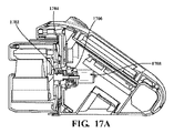
マップ上の点はボクセル内に保たれる。2レベルボクセル実施を図7A及び図7Bに例示している。Μm-1は、最後の走査を処理した後の第1のレベルのマップ700上にあるボクセル702、704のセットを表す。センサ706を取り囲むボクセル704は、部分集合Μm-1を形成し、Sm-1と表記する。6DOFセンサ姿勢
![]()
及び
![]()
を所与として、マップ上でセンサと一緒に移動する対応するSm-1が存在する。センサがマップの境界に近づくと、境界の反対側にあるボクセル725がマップ境界730を拡張するように移動される。移動されたボクセル内の点は消去され、マップの切り取りが生じる。
Maps within voxels Points on maps are kept within voxels. A two-level voxel implementation is illustrated in FIGS. 7A and 7B. Μm -1 represents the set of
![]()
as well as
![]()
, there is a corresponding S m-1 that moves with the sensor on the map. As the sensor approaches the boundary of the map, the
図7Bに例示するように、第2のレベルのマップ750の各ボクセルj(jε∈Sm-1)は、第1のレベルのマップ700のものよりもマグニチュードが小さい
![]()
と表記するボクセルセットによって形成される。走査を整合させる前に、最良の運動推測を用いてεm及びHm内の点がマップ上に投影され、
![]()
(
![]()
)内に埋められる。εm及びHmからの点で占有されたボクセル708は抽出されてQm-1が形成され、走査整合のための3D KD木内に格納される。ボクセル710は、εm及びHmからの点で占有されない。走査整合の完了時に、走査は、マップをなすボクセル708内に融合される。その後、マップ点は一定の密度を維持するようにダウンサイズされる。第1のレベルのマップ700の各ボクセルが第2のレベルのマップ750の部分ボクセルよりも大きい空間容積に対応することは認識することができる。従って、第1のレベルのマップ700の各ボクセルは、第2のレベルのマップ750内の複数の部分ボクセルを含み、第2のレベルのマップ750内の複数の部分ボクセル上にマッピングすることができる。
As illustrated in FIG. 7B, each voxel j (jεεS m−1 ) in the
![]()
is formed by a set of voxels denoted as . Before matching the scans, the points in ε m and H m are projected onto the map using the best motion estimate,
![]()
(
![]()
).
図7A及び図7Bに関して上述したように、マップ情報を格納するために2つのボクセルレベル(第1のレベルのマップ700及び第2のレベルのマップ750)が用いられる。Mm-1に対応するボクセルは、第1のレベルのマップ700を維持するために用いられ、第2のレベルのマップ750内の
![]()
(
![]()
)に対応するボクセルは、走査整合のためのセンサの周囲のマップを取り出すために用いられる。マップは、センサがマップ境界に近づく時にのみ切り取られる。従って、センサがマップの内部を進む時に切り取りは必要ない。別の注目点は、一方が縁点に対し、もう一方が平面点に対する2つのKD木がSm-1内の各個別ボクセルに対して用いられる点である。上述したように、そのようなデータ構造は点検索を高速化することができる。この方式で、
![]()
(
![]()
)内の各個別ボクセルに対して2つのKD木を用いるのとは対照的に複数のKD木の間の検索が回避される。
![]()
(
![]()
)内の各個別ボクセルに対して2つのKD木を用いる場合は、KD木の構築及び保守のためにより多くのリソースを必要とする。
As described above with respect to FIGS. 7A and 7B, two voxel levels (
![]()
(
![]()
) are used to retrieve a map around the sensor for scan alignment. The map is clipped only when the sensor approaches the map boundary. Therefore, no clipping is required when the sensor travels inside the map. Another point to note is that two KD-trees are used for each individual voxel in S m -1 , one for edge points and one for plane points. As mentioned above, such a data structure can speed up point searches. In this method,
![]()
(
![]()
) avoids searching between multiple KD-trees as opposed to using two KD-trees for each individual voxel in .
![]()
(
![]()
) requires more resources for building and maintaining the KD-trees.
表1は、異なるボクセル及びKD木の構成を用いたCPU処理時間を比較している。時間は、閉鎖及び開放された構造化区域及び植物繁茂区域を網羅する様々なタイプの環境から収集した複数のデータセットから平均したものである。1つのボクセルレベルΜm-1のみを用いる時に、KD木の構築及び照会に約2倍の処理時間が生じることがわかる。このは、第2のボクセルレベル
![]()
(
![]()
)がマップを綿密に検索するのに役立つことに起因する。これらのボクセルなしでは、Qm-1内により多くの点が含まれてKD木内に組み込まれる。また、各ボクセルに対してKD木を用いることにより、処理時間は、Μm-1内の全てのボクセルに対してKD木を用いる場合と比較して若干短縮される。
Table 1 compares the CPU processing time using different voxel and KD-tree configurations. Times are averaged from multiple data sets collected from different types of environments covering closed and open structured areas and vegetated areas. It can be seen that the KD-tree construction and query results in about twice the processing time when using only one voxel level Μm -1 . This is the second voxel level
![]()
(
![]()
) helps to search the map closely. Without these voxels, more points in Q m-1 are included and incorporated into the KD-tree. Also, by using KD-trees for each voxel, the processing time is slightly reduced compared to using KD-trees for all voxels within .mu.m -1 .
(表1)
表1.KD木演算における平均CPU処理時間の比較

Table 1. Comparison of average CPU processing time in KD tree operation
並行処理
走査整合は、KD木を構築する段階と、特徴部一致を反復的に求める段階とを含む。この処理は時間を要し、システム内の主な計算を占有する。1つのCPUスレッドは所望の更新周波数を保証することができないが、マルチスレッド実施は、複雑な処理の問題に対応することができる。図8Aは、2つの整合器プログラム812、815が並列で実行される場合を例示している。走査の受信時に、マネージャプログラム810は、走査を最新の利用可能マップと整合させるように配列する。複数の構造及び複数の視覚特徴部を有する集合的な環境で構成される一例では、整合は低速であり、次の走査の到着前に完了することができない可能性がある。2つの整合器812及び815は交互に呼び出される。一方の整合器812では、Pm813a、Pm-2813b、及び更に別のPm-k(k=偶数に関する)813nが、それぞれQm-2813a、Qm-4813a、及び更に別のQm-k(k=偶数に関する)813nと整合される。同様に、第2の整合器815では、Pm+1816a、Pm-1816b、及び更に別のPm-k(k=奇数に関する)816nが、Qm-1816a、Qm-3816a、及び更に別のQm-k(k=奇数に関する)816nと整合される。この交互処理の使用は、処理に対して2倍の時間量を与える可能性がある。構造及び視覚特徴部をほとんど持たないきれいな環境で構成される代替例では、計算は軽い。そのような例(図8B)では、単一の整合器820しか呼び出さなくてもよい。交互処理が必要とされないことから、Pm、Pm-1、が、それぞれQm-1,Qm-2,・・・(827a、827b、827nを参照されたい)と順番に整合される。一般的には2つのスレッドしか必要とされない可能性があるが、この実施は、最大で4つのスレッドを用いるように構成することができる。
Parallel scan matching involves building a KD-tree and iteratively finding feature matches. This process takes time and occupies major computations in the system. A single CPU thread cannot guarantee the desired update frequency, but a multi-threaded implementation can accommodate complex processing problems. FIG. 8A illustrates the case where two
変換統合
最終的な運動推定は、図2に描いている3つのモジュールからの出力の統合である。5Hzの走査整合出力は最も正確なマップを生成し、その一方で50Hzの視覚-慣性オドメトリ出力及び200HzのIMU予測は高周波数運動推定のための統合される。
Transform Integration The final motion estimation is the integration of the outputs from the three modules depicted in FIG. The 5 Hz scan-matched output produces the most accurate maps, while the 50 Hz visual-inertial odometry output and 200 Hz IMU prediction are integrated for high frequency motion estimation.
ロバスト性について
システムのロバスト性は、センサ劣化に対処する機能によって決定される。IMUは、システム内のバックボーンとして確実に機能しているものと常に仮定する。カメラは、劇的な照明変化に影響され、暗い/凹凸のない環境内で又は著しい運動ぼけが存在する時に(それによって視覚特徴部追跡の喪失が引き起こされる)失敗する可能性もある。レーザは、構造のない環境、例えば、単一の平面が大半を占めるシーンに対処することができない。これに代えて、過激な運動に起因するデータの希薄性によってレーザデータの劣化が引き起こされる恐れがある。そのような過激な運動は非常に動的な運動を含む。本明細書で用いる時に、「非常に動的な運動」は、システムの実質的に突然の回転変位又は直線変位又は実質的に大きいマグニチュードを有する連続的な回転運動又は平行移動運動を意味する。本発明の開示の自己運動決定システムは、非常に動的な運動の存在下並びに暗く凹凸及び構造のない環境内で作動することができる。一部の例示的実施形態では、本発明のシステムは、360度毎秒程度の高い回転角速度を受けながら作動することができる。他の実施形態では、システムは、100kphを含むそれ以下の線速度で作動することができる。それに加えて、これらの運動は、角運動と直線運動が結合されたものとすることができる。
About Robustness The robustness of the system is determined by its ability to cope with sensor degradation. Always assume that the IMU is functioning reliably as the backbone in the system. Cameras can also be affected by dramatic lighting changes and fail in dark/smooth environments or when significant motion blur is present (causing loss of visual feature tracking). Lasers cannot cope with environments without structure, eg scenes dominated by a single plane. Alternatively, data sparseness due to extreme motion can cause laser data degradation. Such extreme exercise includes highly dynamic exercise. As used herein, "highly dynamic motion" means substantially abrupt rotational or linear displacements of the system or continuous rotational or translational motions having substantially large magnitudes. The self-motion determination system of the present disclosure can operate in the presence of highly dynamic motion and in dark, uneven and structure-free environments. In some exemplary embodiments, systems of the present invention can operate while undergoing rotational angular velocities as high as 360 degrees per second. In other embodiments, the system can operate at linear velocities up to and including 100 kph. In addition, these motions can be combined angular and linear motions.
視覚-慣性オドメトリモジュールと走査整合モジュールの両方は、式(2)に従って最適化問題を定式化してそれを解く。失敗が発生する時に、それは、劣化した最適化問題に対応し、すなわち、問題の一部の方向の制約が不良状態にあり、解を決定する上でノイズが優勢である。1つの非限定的方法では、問題に関連付けられたλ1,λ2,・・・,λ6と表記する固有値と、v1,v2,・・・,v6と表記する固有ベクトルとを計算することができる。センサの状態空間は6DOF(6つの自由度)を含むことから、6つの固有値/固有ベクトルが存在する。一般性を失うことなく、v1,v2,・・・,v6を大きい順に並べ換えることができる。各固有値は、解がその対応する固有ベクトルの方向にどの程度良好な状態にあるかを表す。固有値を閾値と比較することにより、状態空間内で良好な状態にある方向を劣化方向から分離することができる。h(h=0;1,…,6)を十分に条件付けされた方向の個数とする。2つの行列を次式のように定義することができる。
式(16)
![]()
Equation (16)
![]()
最適化問題を解く時に、初期推測を用いて非線形反復を開始することができる。図2に描いている連続パイプラインを用いて、IMU予測は、視覚-慣性オドメトリのための初期推測を与え、視覚-慣性オドメトリの出力は、走査整合のための初期推測として採用される。追加の2つのモジュール(視覚-慣性オドメトリ及び走査整合モジュール)に対して、xを解とし、更に△xを非線形反復におけるxの更新とし、この場合、△xは、線形化したシステム方程式を解くことによって計算される。最適化処理中に、xを全方向に更新する代わりにxを十分に条件付けされた方向のみに更新し、劣化方向に初期推測を保つことができる。
式(17)
![]()
Equation (17)
![]()
式(17)において、システムは、IMU予測から始めて粗から細の順序で運動に関して求解し、追加の2つのモジュールは、運動を可能な限り求める/精緻化する。問題が良好な状態にある時に、精緻化は6DOFの全てを含むことができる。それとは別に問題が部分的にしか良好な状態にない時に、精緻化は0DOFから5DOFまでを含むことができる。問題が完全に劣化した時に、
![]()
は、ゼロ行列になり、先行モジュールの出力が保たれる。
In equation (17), the system solves for motion in order from coarse to fine, starting with the IMU prediction, and two additional modules determine/refine the motion as much as possible. Refinement can include all 6 DOFs when the problem is in good shape. Alternatively, refinement can include from 0 DOF to 5 DOF when the problem is only partially good. When the problem is completely degraded,
![]()
becomes a matrix of zeros, preserving the output of the preceding module.
式(14)及び式(15)に記述されている姿勢制約に戻ると、これら2つの式が走査整合問題において線形結合されることが認められるであろう。式(16)に定義されているように、
![]()
及び
![]()
は、視覚-慣性オドメトリモジュールからの固有ベクトルを含む行列を表し、
![]()
は、サブシステム内の十分に条件付けされた方向を表し、
![]()
は、劣化方向を表す。組み合わせ制約は次式で与えられる。
式(18)
![]()
![]()
![]()
as well as
![]()
represents the matrix containing the eigenvectors from the visual-inertial odometry module,
![]()
represents a well-conditioned direction in the subsystem, and
![]()
represents the direction of deterioration. The combinatorial constraint is given by the following equation.
Equation (18)
![]()
![]()
カメラが機能している正常な時に、
![]()
が成り立ち、式(18)は、式(14)にあるもののような視覚-慣性オドメトリからの姿勢制約で構成される。しかし、カメラデータが完全に劣化した時に、
![]()
はゼロ行列であり、式(18)は、式(15)によるIMU予測からの姿勢制約で構成される。
During normal times when the camera is functioning,
![]()
and Eq. (18) is constructed with pose constraints from the visual-inertial odometry as in Eq. (14). However, when the camera data is completely degraded,
![]()
is the zero matrix and equation (18) is constructed with the pose constraint from the IMU prediction according to equation (15).
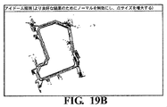
カメラ劣化の事例研究
図9Aに描いているように、視覚特徴部が視覚-慣性オドメトリに対して不十分にしか取得可能ではない時に、IMU予測122は、視覚-慣性オドメトリ問題における十分に条件付けされた方向の個数に依存して完全に又は部分的に点線で表記している視覚-慣性オドメトリモジュール126を迂回する924。続いて走査整合モジュール132は、走査整合のためのレーザ点を局所的に位置合わせすることができる。迂回するIMU予測はドリフトを受ける。レーザフィードバック138は、カメラフィードバック128を補償し、それが取得不能な方向にのみIMUの速度ドリフト及びバイアスを補正する。この場合、カメラデータが劣化していない時には、より高い周波数がカメラフィードバックをより適切なものにすることから、カメラフィードバックは高い優先度を有する。十分な視覚特徴部が見つかる時には、レーザフィードバックは用いられない。
Case Study of Camera Degradation As depicted in FIG. 9A, the
レーザ劣化の事例研究
図9Bに示しているように、走査整合132が運動推定を精緻化するのに環境構造が不十分である時に、視覚-慣性オドメトリモジュール126出力は、レーザ点をマップ上に位置合わせするのに点線で注記しているように走査整合モジュールを完全又は部分的に迂回する930。走査整合問題において十分に条件付けされた方向が存在する時に、レーザフィードバックは、これらの方向に精緻化された運動推定を含む。そうでなければレーザフィードバックは空になる138。
Case Study of Laser Degradation As shown in FIG. 9B, when the environmental structure is insufficient for scan matching 132 to refine the motion estimation, the visual-
カメラ及びレーザ劣化の事例研究
より複雑な例では、カメラとレーザの両方が少なくともある程度劣化する。図10はそのような例を描いている。6つの行を有する垂直バーは、各行が式(16)における固有ベクトルに対応するDOF(自由度)である6DOF姿勢を表す。この例では、視覚-慣性オドメトリ及び走査整合は、各々が運動の3DOFを更新し、他の3DOFにおいて運動を変化しないままに留める。IMU予測1022a~1022fは、初期IMU予測値1002を含むことができる。視覚-慣性オドメトリは、一部の3DOF(1026c,1026e,1026f)を更新し1004、精緻化された予測1026a~1026fを生じる。走査整合は、一部の3DOF(1032b,1032d、1032f)を更新し1006、更に精緻化された予測1032a~1032fを生じる。それぞれ、カメラフィードバック128はカメラ更新1028a~1028fを含み、レーザフィードバック138はレーザ更新1038a~1038fを含む。図10を参照すると、網掛けを持たないセル(1028a、1028b、1028d、1038a、1038c、1038e)は、それぞれのモジュールからのいずれの更新情報も含まない。IMU予測モジュールへの全更新1080a~1080fは、カメラフィードバック128からの更新1028a~1028fとレーザフィードバック138からの更新1038a~1038fとの組み合わせである。フィードバックがカメラ(例えば1028f)とレーザ(例えば1038f)の両方から取得可能である自由度のうちの1又は2以上において、カメラ更新(例えば1028f)は、レーザ更新(例えば1038f)よりも高い優先度を有することができる。
Camera and Laser Degradation Case Study In a more complex example, both the camera and the laser degrade at least to some extent. FIG. 10 depicts such an example. A vertical bar with 6 rows represents a 6DOF pose where each row is the DOF (degree of freedom) corresponding to the eigenvector in Eq. (16). In this example, vision-inertial odometry and scan matching each update the 3DOF of motion and leave motion unchanged in the other 3DOF.
しかし、実際には、視覚-慣性オドメトリモジュールと走査整合モジュールとは異なる周波数で実行する可能性があり、各々は独自の劣化方向を有する可能性がある。走査整合出力からの姿勢の間を内挿するためにIMUメッセージを用いることができる。この方式で、視覚-慣性オドメトリ出力と時間整合された区分的運動を作り出すことができる。
![]()
及び
![]()
をフレームc-1とcの間に視覚-慣性オドメトリによって推定された6DOF運動とし、この場合、
![]()
及び
![]()
が成り立つ。
![]()
及び
![]()
は、時間内挿後に走査整合によって推定された対応する項とする。
![]()
及び
![]()
は、視覚-慣性オドメトリモジュールからの固有ベクトルを含む式(16)に定義された行列とすることができ、この場合、
![]()
は十分に条件付けされた方向を表し、
![]()
は劣化方向を表す。
![]()
及び
![]()
を走査整合モジュールからの同じ行列とする。次式は、組み合わせフィードバックfCを計算する。
式(19)
![]()
式中のfV及びfsは、カメラフィードバック及びレーザフィードバックを表し、以下に続く式で与えられる。
式(20)
![]()
式(21)
![]()
![]()
as well as
![]()
be the 6 DOF motion estimated by visual-inertial odometry between frames c−1 and c, where
![]()
as well as
![]()
holds.
![]()
as well as
![]()
Let be the corresponding term estimated by scan matching after temporal interpolation.
![]()
as well as
![]()
can be the matrix defined in equation (16) containing the eigenvectors from the visual-inertial odometry module, where
![]()
represents a well-conditioned direction, and
![]()
indicates the direction of deterioration.
![]()
as well as
![]()
Let be the same matrix from the scan matching module. The following formula computes the combinatorial feedback f C .
Equation (19)
![]()
f V and f s in the equations represent camera feedback and laser feedback and are given by the equations that follow.
formula (20)
![]()
Equation (21)
![]()
fCは、状態空間の部分空間内で求められた運動しか含まないことに注意されたい。IMU予測からの運動、すなわち、
![]()
及び
![]()
は、次式のようにfCのヌル空間に投影することができる。
式(22)
![]()
![]()
as well as
![]()
can be projected onto the null space of f C as
Equation (22)
![]()
式(3)と式(4)の統合によってbω(t)及びba(t)の関数として定式化されたIMU予測運動を表すために
![]()
及び
![]()
を用いることができる。方位
![]()
は、bω(t)にしか関連しないが、平行移動
![]()
は、bω(t)とba(t)の両方に依存する。バイアスは、次式を解くことによって計算することができる。
式(23)
![]()
![]()
as well as
![]()
can be used. Azimuth
![]()
is only related to b ω (t), but the translation
![]()
depends on both b ω (t) and b a (t). Bias can be calculated by solving the following equation:
Equation (23)
![]()
システムが正常に機能している時には、fCは状態空間を張り、式(22)における
![]()
及び
![]()
はゼロ行列である。相応に、bω(t)及びba(t)は、fCから計算される。劣化した時に、IMU予測運動
![]()
及び
![]()
は、運動を求めることができない(例えば、図10の組み合わせフィードバックの白色の行1080a)方向に用いられる。結果は、先に計算されたバイアスがこれらの方向に保たれることである。
When the system is functioning normally, f C spans the state space and in Eq. (22)
![]()
as well as
![]()
is a zero matrix. Correspondingly, b ω (t) and b a (t) are calculated from f C . IMU predictive motion when degraded
![]()
as well as
![]()
is used in directions where motion cannot be determined (eg,
実験
スキャナを用いた試験
2つのセンサ組に対してオドメトリ及びマッピング側壁システムを検証した。第1のセンサ組では、Velodyneライダー(商標)HDL-32EレーザスキャナをUI-1220SE単色カメラ及びXsens(登録商標)MTi-30 IMUに取り付けた。このレーザスキャナは、360°の水平FOV、40°の垂直FOVを有し、5Hzの回転速度で0.7百万点/秒を感受する。カメラは、752ピクセル×480ピクセルの解像度、76°の水平FOV及び50Hzのフレーム速度に構成した。IMU周波数を200Hzに設定した。第2のセンサ組では、Velodyneライダー(商標)VLP-16レーザスキャナを同じカメラ及びIMUに取り付けた。このレーザスキャナは360°の水平FOV、30°の垂直FOVを有し、5Hzの回転速度で0.3百万点/秒を感受する。各センサ組は、街路及び路外地それぞれの上で走らせたデータ収集車両に取り付けた。
experiment
Testing with Scanner The odometry and mapping sidewall system was validated against two sensor sets. In the first sensor set, a Velodyne Lidar™ HDL-32E laser scanner was attached to a UI-1220SE monochromatic camera and an Xsens® MTi-30 IMU. This laser scanner has a horizontal FOV of 360°, a vertical FOV of 40°, and is sensitive to 0.7 million points/second at a rotation rate of 5 Hz. The camera was configured for a resolution of 752 pixels by 480 pixels, a horizontal FOV of 76° and a frame rate of 50 Hz. The IMU frequency was set to 200 Hz. For the second sensor set, a Velodyne Lidar™ VLP-16 laser scanner was attached to the same camera and IMU. This laser scanner has a horizontal FOV of 360°, a vertical FOV of 30°, and is sensitive to 0.3 million points/second at a rotation speed of 5 Hz. Each sensor set was attached to a data collection vehicle that ran on streets and off-roads respectively.
両方のセンサ組に関して、最大で300個のHarrisコーナを追跡した。視覚特徴部を均等に分散させるために、画像は、各々が最大で10個の特徴部を設ける5×6個の同一の部分領域へと分離した。各部分領域内の特徴部数を維持するために、追跡が特徴部を見失った時に新しい特徴部を生成した。 Up to 300 Harris corners were tracked for both sensor sets. In order to distribute the visual features evenly, the image was separated into 5×6 identical sub-regions, each providing up to 10 features. To maintain the number of features in each subregion, new features were generated when tracking missed features.
このソフトウェアは、2.6GHzのクワッドコアプロセッサ(各コア上に2つのスレッドで全体として8つのスレッド)及び内蔵GPUを有するラップトップコンピュータ上でロボットオペレーティングシステム(ROS)を実行するLinux(登録商標)システムで稼働する。視覚特徴部追跡がGPU及びCPUそれぞれの上で稼働する2つのバージョンのソフトウェアを実施した。処理時間を表2に示している。視覚-慣性オドメトリ(図2の126)によって費やされる時間は、環境又はセンサ構成に関連してそれ程大きく変動することはない。GPUバージョンでは、視覚-慣性オドメトリは、50Hzで実行されるCPUスレッドの約25%を消費する。CPUバージョンでは、視覚-慣性オドメトリはスレッドの約75%を占有する。センサの第1の組は、第2のセンサ組よりも若干長めの処理時間を生じる。このことは、スキャナがより多くの点を感受し、プログラムが深度マップを維持して深度を視覚特徴部に関連付けるのにより多くの時間を必要とすることに起因する。 This software runs Linux® running Robotic Operating System (ROS) on a laptop computer with a 2.6 GHz quad-core processor (2 threads on each core for a total of 8 threads) and an integrated GPU. work in the system. Two versions of the software were implemented with visual feature tracking running on GPU and CPU respectively. Processing times are shown in Table 2. The time spent by the visual-inertial odometry (126 in FIG. 2) does not vary significantly with respect to environment or sensor configuration. On the GPU version, the visual-inertial odometry consumes about 25% of the CPU threads running at 50 Hz. In the CPU version, the visual-inertial odometry occupies about 75% of the threads. The first set of sensors yields slightly longer processing times than the second set of sensors. This is due to the scanner sensing more points and the program needing more time to maintain the depth map and relate depth to visual features.
走査整合(図2の132)は、より長く、更に環境及びセンサ構成に関連して変動する処理時間を消費する。第1のセンサ組では、走査整合は、構造化環境内で作動させた場合に5Hzで実行されるスレッドの約75%を占有する。しかし、植物繁茂環境内では、マップ上により多くの点が位置合わせされ、プログラムは、一般的にスレッドの約135%を消費する。第2のセンサ組では、スキャナはより少ない点しか感受しない。走査整合モジュール132は、環境に依存してスレッドの約50~95%を用いる。IMU予測(図2の132)によって費やされる時間は、他の2つのモジュールと比較して無視することができる。
Scan matching (132 in FIG. 2) consumes a longer and variable processing time related to environment and sensor configuration. For the first sensor set, scan matching occupies approximately 75% of the threads running at 5 Hz when operating in a structured environment. However, within a vegetative environment, where more points are aligned on the map, the program typically consumes about 135% of threads. With the second set of sensors, the scanner senses fewer points. The
精度試験
本提案のシステムの精度を評価するための試験を実施した。これらの試験では、第1のセンサ組を用いた。センサは、大学キャンパスを巡って走る路外車両上に装着した。16分以内の2.7kmの走行の後に、キャンパスマップを構築した。試験にわたる平均速度は2.8m/sであった。
Accuracy Test A test was performed to evaluate the accuracy of the proposed system. These tests used the first set of sensors. The sensor was mounted on an off-road vehicle driving around the university campus. A campus map was constructed after a 2.7 km run within 16 minutes. The average velocity over the test was 2.8 m/s.
(表2)
表2.第1及び第2のセンサ組を用いた平均CPU処理時間

Table 2. Average CPU Processing Time Using First and Second Sensor Sets
試験にわたる運動推定ドリフトを評価するために、推定軌道及び位置合わせしたレーザ点を衛星画像上に位置合わせされた。この場合、地上のレーザ点を手作業で除去した。軌道を衛星画像上の街路と整合させることにより、水平誤差の上限が<1:0mであることが判明した。また、建物を同じ階で比較することによって垂直誤差が<2:0mであることも判明した。それにより、終了時点で進行距離の<0:09%である総相対位置ドリフトが与えられる。測定値に対して精度を保証することができず、従って、位置ドリフトの上限のみを計算したことが認められるであろう。 The estimated trajectories and aligned laser points were aligned on satellite imagery to assess motion estimation drift over the test. In this case, the laser spot on the ground was manually removed. By matching the trajectory with the street on the satellite imagery, an upper bound on the horizontal error was found to be <1:0 m. A vertical error of <2:0 m was also found by comparing buildings on the same floor. This gives a total relative position drift that is <0:09% of the distance traveled at the end. It will be appreciated that accuracy could not be guaranteed for the measurements, so only an upper bound on position drift was calculated.
更に、同じセンサを乗用車の上に装着してより包括的な試験を実施した。乗用車を構造化道路上で9.3kmの行程にわたって走らせた。経路は、植物繁茂環境、橋、丘陵地、及び交通量の多い街路を通り、最終的に開始位置に戻るものであった。標高は経路に沿って70mにわたって変化した。信号機を待つことを除き、試験中の車両速度は9~18m/sの間であった。経路の始点と終点の両方において見られる建物が2箇所に登録されることが判明した。2箇所の登録は、経路長にわたる運動推定ドリフトに起因して発生する。従って、第1の登録は試験の開始時における車両に対応し、第2の登録は試験の終了時における車両に対応する。隔たりの測定結果は<20mであり、終了時に進行距離の<0:22%の相対位置誤差が生じた。 Additionally, a more comprehensive test was performed with the same sensor mounted on a passenger car. A passenger car was driven over a 9.3 km journey on a structured road. The route passed through vegetated environments, bridges, hills, and busy streets, and finally returned to the starting position. Elevation varied over 70m along the route. Vehicle speed during the test was between 9 and 18 m/s, except for waiting for traffic lights. It was found that buildings seen at both the start and end of the route were registered twice. Two registrations occur due to motion estimation drift over the path length. Thus, the first registration corresponds to the vehicle at the beginning of the test and the second registration corresponds to the vehicle at the end of the test. Distance measurements were <20 m, resulting in a relative position error of <0:22% of traveled distance at termination.
システム内の各モジュールは全体の精度に寄与する。図11は、精度試験における推定軌道を描いている。視覚-慣性オドメトリシステムによって生成されたモバイルセンサの軌道の第1の軌道プロット1102は、IMUモジュール122及び視覚-慣性オドメトリモジュール126(図2を参照されたい)を用いたものである。第1の軌道プロット1102において用いた構成は、図9Bに描いているものと同様である。第2の軌道プロット1104は、IMUモジュール122からのIMU予測を視覚-慣性オドメトリを迂回して走査整合モジュール132に直接転送することに基づくものである。この構成は、図9Aに描いているものと同様である。完全なパイプラインの第3の軌道プロット1108は、IMUモジュール122と視覚-慣性オドメトリモジュール126と走査整合モジュール132との組み合わせ(図2を参照されたい)に基づくものであり、最小量のドリフトしか持たない。最初の2つの構成、軌道プロット1102及び1104の位置誤差は、それぞれ約4倍及び2倍大きい。
Each module in the system contributes to the overall accuracy. FIG. 11 depicts estimated trajectories in an accuracy test. A
第1の軌道プロット1102及び第2の軌道プロット1104は、個々のセンサの劣化に遭遇した時に予測されるシステム性能と見なすことができる。走査整合が劣化した場合(図9Bを参照されたい)には、システムは、第1の軌道プロット1102によって示されるモードに劣化する。視覚が劣化した場合(図9Aを参照されたい)には、システムは、第2の軌道プロット1104によって示されるモードに劣化する。センサのうちのいずれも劣化していない場合(図2を参照されたい)には、システムは、最適化機能の全てを組み込み、軌道プロット1108を生じる。別の例では、システムは、IMU予測を初期推測として採用するが、レーザ周波数(5Hz)で稼働することができる。システムは、第4の軌道プロット1106を発生させる。結果として得られる精度は、視覚-慣性オドメトリを通り越してレーザと直接結合されたIMUを用いた第2の軌道プロット1104と比較して僅かにしか良好ではない。この結果は、全ての制約を重ね合わせて問題を解く場合にカメラの機能性が十分に活用されないことを示している。
The
システムの別の精度試験は、元の1×速度及び加速した2×速度で進むモバイルセンサを含むものであった。2×速度で進む時に、3つ全てのセンサに関してデータフレームを1枚置きに省き、試験を通してより過激な運動が生じた。その結果を表3に記載している。各速度で3つの構成を評価した。2×速度では、1×速度での精度と比較して視覚-慣性オドメトリ構成及びIMU+走査整合構成の精度は、進行距離の0.54%及び0.38%という大幅な比率で低減する。しかし、完全なパイプラインは、僅か0.04%という非常に僅かな比率でしか精度を低減させない。この結果は、カメラとレーザとが互いに補償し合って全体的な精度を保つことを示している。このことは、特に運動が過激な時に確かである。 Another accuracy test of the system involved a mobile sensor traveling at the original 1x velocity and an accelerated 2x velocity. Every other frame of data was omitted for all three sensors when traveling at 2x velocity, resulting in more extreme motion throughout the test. The results are listed in Table 3. Three configurations were evaluated at each speed. At 2× speed, the accuracy of the visual-inertial odometry configuration and the IMU+scan matching configuration compared to the accuracy at 1× speed decreases at a significant rate of 0.54% and 0.38% of distance traveled. However, the full pipeline reduces accuracy by a very small percentage of only 0.04%. This result shows that the camera and laser compensate each other to maintain overall accuracy. This is especially true when the exercise is extreme.
表3.進行距離の百分率としての相対位置誤差 Table 3. Relative position error as a percentage of distance traveled
(表3)
(1×速度での誤差は、図11の軌道に対応する)

(The error at 1x velocity corresponds to the trajectory in Figure 11)
図12を参照すると、双方向情報フローの例示的かつ非限定的実施形態が示されている。例示するように、IMU予測モジュールと視覚-慣性オドメトリモジュールと走査整合精緻化モジュールとを含む3つのモジュールが、粗から細に段階的に問題を解く。データ処理フローは左から右へのものであり、3つのモジュールをそれぞれ通過し、それに対してフィードバックフローは右から左へのものであり、IMUのバイアスを補正する。 Referring to FIG. 12, an exemplary, non-limiting embodiment of bi-directional information flow is shown. As illustrated, three modules solve the problem step by step from coarse to fine, including an IMU prediction module, a visual-inertial odometry module, and a scan matching refinement module. The data processing flow is left-to-right and passes through each of the three modules, whereas the feedback flow is right-to-left and corrects for IMU bias.
図13a及び図13bを参照すると、動的再構成可能システムの例示的かつ非限定的実施形態が示されている。図13aに例示するように、視覚-慣性オドメトリにとって視覚特徴部が不十分である時に、IMU予測は視覚-慣性オドメトリモジュールを(部分的に)迂回してレーザ点を局所的に位置合わせする。それに対して、図13bに例示するように、走査整合にとって環境構造が不十分である時に、視覚-慣性オドメトリ出力が走査整合精緻化モジュールを(部分的に)迂回してレーザ点をマップ上に位置合わせする。 Referring to Figures 13a and 13b, an exemplary, non-limiting embodiment of a dynamically reconfigurable system is shown. As illustrated in FIG. 13a, the IMU prediction (partially) bypasses the visual-inertial odometry module to align the laser spot locally when the visual features are insufficient for visual-inertial odometry. In contrast, as illustrated in FIG. 13b, the visual-inertial odometry output (partially) bypasses the scan-match refinement module to map laser points onto the map when the environmental structure is insufficient for scan-match. Align.
図14を参照すると、IMUバイアス補正のための優先度フィードバックの例示的かつ非限定的実施形態が示されている。例示するように、垂直バーは6DOF姿勢を表し、各行は1つのDOFである。劣化した時に、表記された6つ全ての行が「IMU」である左のIMU予測から始めて、視覚-慣性オドメトリが3DOFにおいて行が「カメラ」と表記されることになる更新を行い、続いて走査整合が別の3DOFにおいて行が「レーザ」と表記されることになる更新を行う。カメラフィードバックとレーザフィードバックとは左にある垂直バーのように組み合わせられる。カメラフィードバックは高めの優先度を有し、レーザフィードバックからの「レーザ」行は、カメラフィードバックからの「カメラ」行が存在しない場合にのみ埋められる。 Referring to FIG. 14, an exemplary, non-limiting embodiment of priority feedback for IMU bias correction is shown. As illustrated, vertical bars represent 6 DOF poses and each row is one DOF. When degraded, starting with the left IMU prediction where all 6 rows labeled 'IMU', the visual-inertial odometry makes an update where the row is labeled 'camera' at 3DOF, followed by Scan Match makes an update that will cause the row to be labeled "LASER" in another 3 DOF. Camera feedback and laser feedback are combined like the vertical bar on the left. Camera feedback has a higher priority and the "laser" row from laser feedback is filled only if the "camera" row from camera feedback does not exist.
図15a及び図15bを参照すると、マップの二層ボクセル表現の例示的かつ非限定的実施形態が示されている。マップ上のボクセルMm-1(図15a内の全てのボクセル)及びセンサを取り囲むボクセルSm-1(点塗りつぶし表示ボクセル)が例示されている。Sm-1は、Mm-1の部分集合である。センサがマップの境界に近づいた時に、境界の反対側(最下行)にあるボクセルがマップ境界を拡張するように移動される。移動されたボクセル内の点はクリアされ、マップは切り取られる。図15bに例示するように、各ボクセルj(j∈Sm-1)(図15aの点塗りつぶし表示ボクセル)は、マグニチュードが小さいボクセルのセット
![]()
((図15b)の全てのボクセル
![]()
)によって形成される。走査整合の前に、レーザ走査は、最良の運動推測を用いてマップ上に投影することができる。走査からの点によって占有された
![]()
(
![]()
)内のボクセルをクロスハッチングで標記している。続いて走査整合のためのクロスハッチング表示ボクセル内のマップ点が抽出されて3D KD木内に格納される。
Referring to Figures 15a and 15b, an exemplary and non-limiting embodiment of a two-layer voxel representation of a map is shown. A voxel M m-1 on the map (all voxels in FIG. 15a) and a voxel S m-1 surrounding the sensor (dotted fill voxels) are illustrated. S m-1 is a subset of M m-1 . When the sensor approaches the map boundary, the voxels on the opposite side of the boundary (bottom row) are moved to extend the map boundary. Points within the moved voxels are cleared and the map is clipped. As illustrated in FIG. 15b, each voxel j (jεS m−1 ) (dot-filled representation voxel in FIG. 15a) is a set of voxels with small magnitudes
![]()
(All voxels in (Fig. 15b)
![]()
). Prior to scan registration, the laser scan can be projected onto the map using the best motion estimate. occupied by points from the scan
![]()
(
![]()
) are marked with cross hatching. The map points in the cross-hatched voxels for scan matching are then extracted and stored in the 3D KD-tree.
図16を参照すると、走査整合のマルチスレッド処理の例示的かつ非限定的実施形態が示されている。例示するように、マネージャプログラムが、別個のCPUスレッド上で実行される複数の整合器プログラムを呼び出し、走査を利用可能な最新のマップに整合させる。図16aは2スレッドの場合を示している。走査Pm,Pm-1,・・・は、各整合器上でQm,Qm-1,・・・と整合され、処理に対して2倍の時間量が与えられる。それと比較して、図16bは、1スレッドの場合を示しており、この場合、Pm,Pm-1,・・・は、Qm,Qm-1,・・・と整合される。この実施は、最大で4つのスレッドを用いて動的に構成可能である。 Referring to FIG. 16, an exemplary, non-limiting embodiment of multi-threaded processing of scan matching is shown. Illustratively, a manager program calls multiple matcher programs running on separate CPU threads to match scans to the latest available maps. FIG. 16a shows the two-thread case. Scans P m , P m-1 , . . . are aligned with Q m , Q m-1 , . In comparison, FIG. 16b shows the one-thread case, where P m , P m-1 , . . . are aligned with Q m , Q m-1 , . This implementation is dynamically configurable with up to four threads.
実施形態では、実時間SLAMシステムを実時間ナビゲーションシステムとの組み合わせで用いることができる。実施形態では、SLAMシステムは、ライダー又はレーダベースの障害物検出システム、視覚ベースの障害物検出システム、熱ベースのシステム、又は同様のもののような障害物検出システムとの組み合わせで用いることができる。この障害物検出は、人々、ペット、又は同様のもののような活動障害物を運動検出、熱検出、電場又は磁場検出するか、又は他の機構等によって検出する段階を含むことができる。 In embodiments, a real-time SLAM system may be used in combination with a real-time navigation system. In embodiments, the SLAM system may be used in combination with obstacle detection systems such as lidar or radar-based obstacle detection systems, vision-based obstacle detection systems, thermal-based systems, or the like. This obstacle detection may include detecting activity obstacles such as people, pets, or the like, such as by motion detection, heat detection, electric or magnetic field detection, or other mechanisms.
実施形態では、SLAMシステムに近隣反射を与える物体のような近距離特徴部、並びに近距離特徴部の間にある空間又は近距離特徴部内の開口を通して走査することができる品目のような遠距離特徴部のマッピングを含むことができる空間のマッピングを示すために、環境の特徴部を走査することによって確立された点クラウドは、SLAMの一部を形成する画面のような上に表示することができる。例えば、室内の様々な点において異なる室外要素を窓又はドアを通して走査することができることから、マッピング器が室内を動き回る時に隣接する廊下にある品目をそのような空間又は開口を通して走査することができる。この場合、結果として得られる点クラウドは、直近の環境及びこの環境の外側にある遠距離要素の部分マッピングの包括的なマッピングデータを含むことができる。このように、SLAMシステムは、「杭柵」を通しての空間のマッピングを近距離内にある空間又は開口(すなわち柵内の間隙)を通して遠距離物の識別によって行う段階を含むことができる。遠距離データは、例えばマッピング器が網羅的にマッピングされた空間(点クラウドの密度に起因して十分に理解された方位及び位置を有する)から疎にのみマッピングされた空間(新しい部屋等)へと移動する時に一貫した場所推定を維持するようなマッピング器が空間から空間へと移動する時にシステムがSLAMの方位を定めることを補助するために用いることができる。ユーザが近距離の場所から遠距離の場所に移動する時に、SLAMシステムは、点クラウドの相対的な密度又は疎度を用いて、例えば、SLAMの一部を形成するユーザインターフェースを通じてマッピング器を誘導することができ、例えば、別の空間から開口を通して見ることができない遠距離部分へとマッピング器を導くことができる。 In embodiments, near-range features, such as objects that provide near-field reflections to the SLAM system, and far-range features, such as items that can be scanned through spaces between the near-range features or apertures within the near-range features. A point cloud established by scanning features of the environment to show spatial mapping, which can include spatial mapping, can be displayed on a screen-like surface forming part of SLAM. . For example, because different outdoor elements can be scanned through windows or doors at various points in the room, items in adjacent corridors can be scanned through such spaces or openings as the mapper moves around the room. In this case, the resulting point cloud may contain comprehensive mapping data of the immediate environment and partial mapping of far-field elements outside this environment. Thus, the SLAM system can include mapping of the space through the "pile fence" by identifying distant objects through spaces or openings (ie gaps in the fence) that are within the near range. Far-range data, for example, allows the mapper to move from an exhaustively mapped space (with well-understood orientation and position due to the density of the point cloud) to a only sparsely mapped space (such as a new room). A mapper that maintains a consistent location estimate as it moves can be used to help the system orient the SLAM as it moves from space to space. As the user moves from a near-field location to a far-field location, the SLAM system uses the relative density or sparsity of the point cloud to guide the mapper, e.g., through a user interface that forms part of SLAM. For example, the mapper can be directed from another space to a far portion that cannot be seen through the aperture.
実施形態では、SLAMシステムからの点クラウドマップは、カメラ、及びセンサなどのような他の入力からのマッピングと組み合わせることができる。例えば、飛行又は宇宙船の例では、飛行機、ドローン、又は他の飛行モバイルプラットフォームは、SLAMシステムに対する基準データとして用いることができ(例えば、走査から生じる点クラウドをGPS基準の場所に結び付ける)、又は例えば他のシステムからの出力上へのオーバーレイとして更に別の走査データを表示するための基準データを走査から取得することができる他の距離測定機器及び地理的定位機器が既に装備されている可能性がある。例えば、従来のカメラ出力は、オーバーレイとして点クラウドデータと一緒に示すことができ、又はその逆も同様である。 In embodiments, the point cloud map from the SLAM system can be combined with mapping from other inputs such as cameras and sensors. For example, in the flying or spacecraft example, an airplane, drone, or other flying mobile platform can be used as reference data for the SLAM system (e.g., linking the point cloud resulting from the scan to a GPS reference location), or Possibly already equipped with other range finding and geolocation equipment capable of obtaining reference data from the scan for displaying further scan data, e.g. as an overlay on output from other systems. There is For example, conventional camera output can be shown together with point cloud data as an overlay, or vice versa.
実施形態では、SLAMシステムは、各特徴部からの帰還信号の反射強度を示すデータを含む点クラウドを提供することができる。この反射強度は、システムに対する信号の有効性を決定すること、特徴部が互いにどの程度関係するかを決定すること、面IR反射率を決定すること、及び同様のことを補助するために用いることができる。実施形態では、この反射強度は、マップ内への点クラウド表示を操作するための基準として用いることができる。例えば、SLAMシステムは、所与の特徴部、材料、構造、又は同様のものに関する信号の反射率を強調表示するためにある程度の色対比を導入することができる(自動的に又はユーザ制御下で)。それに加えて、色及び反射係数の情報を拡張するためにSLAMシステムを他のシステムと結合することができる。実施形態では、点クラウド内の点のうちの1又は2以上は、強度パラメータ、密度パラメータ、時間パラメータ、及び地理空間的場所パラメータのような取得データのパラメータに対応する色を用いて表示することができる。点クラウドの着色は、SLAMシステムが内部で作動している環境の要素又は特徴部、及び/又は点クラウド自体の取得処理の特徴部の要素をユーザが理解して解析するのを補助することができる。例えば、地理空間的区域内で取得される点の個数を示す密度パラメータを用いて、多くのデータ点が取得される区域を表す色と、データが疎らであって、「実」データではなく偽像の存在を示唆する別の色とを決定することができる。色は、例えば、走査が行われる時に一連の色を通して推移する時間を示すこともでき、その結果、SLAM走査を実施する経路の明確な表示が生じる。着色は、様々な特徴部の間で区別するため(例えば、空間内の家具を壁と比較する)、美術的効果を与えるため、注目区域を強調表示するため(例えば、走査観察者の注目を求めて関連機器を強調表示する)のような表示目的で行うこともできる。 In embodiments, the SLAM system may provide a point cloud containing data indicative of the return signal strength from each feature. This reflected strength can be used to help determine the effectiveness of the signal to the system, determine how features relate to each other, determine surface IR reflectance, and the like. can be done. In embodiments, this reflection intensity can be used as a basis for driving the point cloud display into the map. For example, SLAM systems can introduce some degree of color contrast (either automatically or under user control) to highlight the reflectance of the signal for a given feature, material, structure, or the like. ). Additionally, the SLAM system can be combined with other systems to extend the color and reflection coefficient information. In embodiments, one or more of the points in the point cloud are displayed using colors corresponding to parameters of the acquired data such as intensity parameters, density parameters, time parameters, and geospatial location parameters. can be done. Coloring of the point cloud may assist the user in understanding and analyzing the elements or features of the environment within which the SLAM system operates and/or the features of the acquisition process of the point cloud itself. can. For example, with a density parameter that indicates the number of points acquired within a geospatial area, a color representing an area where many data points Another color that indicates the presence of an image can be determined. Colors can also indicate, for example, the time it takes to transition through a series of colors as a scan is performed, resulting in a clear indication of the path to perform the SLAM scan. Coloring may be used to distinguish between various features (e.g., compare furniture in a space with walls), to provide artistic effects, to highlight areas of interest (e.g., to draw the attention of a scanning observer). It can also be done for display purposes, such as highlighting the relevant equipment for which you are asking.
実施形態では、SLAMシステムは、「影」(点クラウドが、走査からの比較的少ないデータ点しか持たない区域)を識別することができ、追加の走査を必要とする区域を強調表示することができる(例えばユーザインターフェースを通じて)。例えば、そのような区域は、点クラウドを表示するSLAMシステムの視覚インターフェース内で影区域がレーザ走査によって十分に「塗色」又は網羅されるまで明滅する又は特定の色で描画することができる。そのようなインターフェースは、まだ走査されていない視野内の区域を強調表示するユーザに対するいずれかのインジケータ(視覚的、文字ベース、音声ベース、又は同様のもの)を含むことができ、いずれかのそのようなインジケータを用いて直接的に又は外部デバイス(ユーザのモバイル電話等)を通じてユーザの注目を得ることができる。他の例示的かつ非限定的実施形態により、本発明のシステムは、未走査領域を識別するために現在走査との比較のためのそれまでに構築された点クラウド及びマップなどのようなSLAM上に格納されたデータの外部データを参照することができる。 In embodiments, the SLAM system can identify "shadows" (areas where the point cloud has relatively few data points from the scan) and highlight areas that require additional scanning. (eg, through a user interface). For example, such an area may blink or be drawn in a particular color within the visual interface of the SLAM system displaying the point cloud until the shadowed area has been sufficiently "painted" or covered by the laser scanning. Such an interface may include any indicator (visual, text-based, audio-based, or the like) to the user that highlights areas within the field of view that have not yet been scanned; Such indicators can be used to get the user's attention either directly or through an external device (such as the user's mobile phone). According to another exemplary and non-limiting embodiment, the system of the present invention uses SLAM's previously constructed point clouds and maps, etc., for comparison with the current scan to identify unscanned regions. External data of data stored in can be referenced.
実施形態では、本明細書に開示する方法及びシステムは、正確な位置及び方位情報を決定するために、又はレーザ走査からの反射信号に基づいて環境特徴部を示す点クラウドデータで構成されるマップを発生させるために外部システムによる処理又は計算を必要とすることなく稼働点において実時間測位出力を提供するSLAMシステムを含む。実施形態では、本明細書に開示する方法及びシステムは、レーザ走査から収集されたデータの後処理を必要とすることなく実時間測位情報を提供するSLAMシステムを含むこともできる。 In embodiments, the methods and systems disclosed herein use maps composed of point-cloud data indicating environmental features to determine precise position and orientation information, or based on reflected signals from laser scanning. includes a SLAM system that provides real-time positioning output at the operating point without requiring processing or computation by an external system to generate . In embodiments, the methods and systems disclosed herein may also include a SLAM system that provides real-time positioning information without requiring post-processing of data collected from laser scanning.
実施形態では、SLAMシステムは、車両ナビゲーションシステム(無人飛行体、ドローン、モバイルロボット、無人水中車両、自動運転車両、半自動車両、及び多くの他のもの等のためのもの)のような様々な外部システムと統合することができる。実施形態では、SLAMシステムは、車両がそれ自体の環境の範囲内でGPSのような外部システムに頼ることなく進むことを可能にするために用いることができる。 In embodiments, the SLAM system may be used in a variety of external applications such as vehicle navigation systems (such as for unmanned air vehicles, drones, mobile robots, unmanned underwater vehicles, autonomous vehicles, semi-autonomous vehicles, and many others). Can be integrated with the system. In embodiments, the SLAM system can be used to allow a vehicle to navigate within its own environment without relying on external systems such as GPS.
実施形態では、SLAMシステムは、位置、方位、又は同様のものの現在推定に関して信頼性レベルを決定することができる。信頼性レベルは、走査において取得可能な点の密度、走査において取得可能な点の直交度、環境の幾何学形状、又は他の因子、又はこれらの組み合わせに基づくものとすることができる。信頼性レベルは、走査のセグメントを低信頼性セグメント、高信頼性セグメント、又は同様のものと呼ぶことができるように走査のルートに沿う各点における位置及び方位の推定に帰するものとすることができる。低信頼性セグメントは、追加の走査、他の技術の使用(外部データに基づいて調節を加えること等)、又は同様のことのために強調表示することができる。例えば、走査が閉ループ(走査の終了点が、既知の最初の場所での開始点と同じである)で行われる場合に、計算された終了場所と開始場所の間のいずれかの差異は、開始場所と終了場所の一致を回復するようにある一定の走査セグメントに対する場所推定を優先的に調節することによって解決することができる。低信頼性セグメント内の場所及び位置の情報は、高信頼性セグメントと比較して優先的に調節することができる。このように、SLAMシステムは、閉ループ走査に対して信頼性ベースの誤差補正を用いることができる。 In embodiments, the SLAM system may determine a confidence level for the current estimate of position, orientation, or the like. The confidence level may be based on the density of points obtainable in the scan, the orthogonality of points obtainable in the scan, the geometry of the environment, or other factors, or a combination thereof. Confidence levels shall be attributed to position and orientation estimates at each point along the route of the scan so that segments of the scan may be referred to as low-confidence segments, high-confidence segments, or the like. can be done. Low-confidence segments may be highlighted for additional scanning, use of other techniques (such as making adjustments based on external data), or the like. For example, if the scan is done in a closed loop (the end point of the scan is the same as the start point at the first known location), any difference between the computed end location and the start location will be the start It can be solved by preferentially adjusting the location estimate for certain scan segments to restore agreement between location and end location. Location and location information in the low-trust segment can be preferentially adjusted compared to the high-trust segment. Thus, the SLAM system can use reliability-based error correction for closed-loop scanning.
この信頼性ベースの調節の例示的かつ非限定的実施形態では、最初にGeorgia TechのMichael Kaess及びFrank Dellaertによって開発された区分的平滑化及びマッピング(iSAM)アルゴリズムの導出(M.Kaess、A.Ranganathan、及びF.Dellaert著「iSAM:区分的平滑化及びマッピング(iSAM:Incremental Smoothing and Mapping)」、IEEE Trans.on Robotics(TRO)、第24巻、第6号、2008年12月、1365~1378ページ、PDF)を用いることができる。このアルゴリズムは、マップデータを「セグメント」で処理し、セグメント間の整合の残余誤差を最適化するようにこれらのセグメントの相対位置を反復的に精緻化する。それにより、全てのデータを閉ループ内で調節することによってループを閉じることが可能になる。多くのセグメント化の点は、アルゴリズムがデータを大幅に移動させることを可能にし、それに対して少ないセグメント化の点は高い剛性を生じる。 In an exemplary and non-limiting embodiment of this confidence-based adjustment, the derivation of the piecewise smoothing and mapping (iSAM) algorithm, originally developed by Michael Kaess and Frank Dellaert of Georgia Tech (M. Kaess, A. Ranganathan, and F. Dellaert, "iSAM: Incremental Smoothing and Mapping", IEEE Trans. on Robotics (TRO), Vol. 24, No. 6, Dec. 2008, 1365- 1378 page, PDF ) can be used. The algorithm processes the map data in "segments" and iteratively refines the relative positions of these segments so as to optimize the residual error of alignment between segments. It allows closing the loop by adjusting all the data in the closed loop. Many segmentation points allow the algorithm to move the data significantly, whereas fewer segmentation points result in high stiffness.
セグメント化のための点が整合信頼性メトリックに基づいて選択される時に、これを利用してループ閉鎖処理が正確なマップセクションの方々に局所誤差を分散させないように低い信頼性を有する領域内でマップを柔軟にし、高い信頼性を有する区域内で剛性にすることができる。このことは、各点に「柔軟性」を割り当てるようにセグメント化の点に重み付けし、この因子に基づいて誤差を分散させることによって更に改良することができる。 When points for segmentation are selected based on the consistency confidence metric, this is taken advantage of in regions with low confidence so that the loop closure process does not spread local errors around the correct map section. Maps can be flexible and rigid in areas with high confidence. This can be further improved by weighting the segmentation points to assign a "flexibility" to each point and spreading the error based on this factor.
実施形態では、点クラウドの区域又はセグメントに関する信頼性尺度を用いて、例えば改善されたSLAM走査を実現するために追加の走査を行うようにユーザを導くことができる。実施形態では、信頼性尺度は、点の密度、及び点の直交度などの組み合わせに基づくものとすることができ、より的確な走査を可能にするようにユーザを導くことができる。点の密度及び点の直交度のような走査属性は、走査が進行するにつれて実時間で決定することができることに注意されたい。同様に、システムは、低信頼性尺度を生じる可能性が高い走査環境の幾何学形状を感知することができる。例えば、平滑な壁を有する長い廊下は、1つの走査セグメントを次のセグメントから区別するためのいずれの不規則性も示さない可能性がある。そのような事例では、システムは、そのような環境内で取得された走査データに対して低めの信頼性尺度を割り当てることができる。システムは、低減する信頼性を決定し、走査を通して指示(「減速」、「左に方向転換」、又は同様のもの等)によってユーザを誘導するためにライダー、カメラ、及び場合によっては他のセンサのような様々な入力を用いることができる。他の実施形態では、システムは、所望のものよりも低い信頼性の区域をユーザインターフェース等を通じてユーザに表示し、それと同時にユーザが低信頼性の区域、容積、又は領域を更に走査することを可能にするように補助を与えることができる。 In embodiments, a confidence measure for an area or segment of the point cloud may be used to guide the user to perform additional scans, eg, to achieve an improved SLAM scan. In embodiments, the confidence measure may be based on a combination of point density, point orthogonality, etc., and may guide the user to enable more accurate scanning. Note that scanning attributes such as point density and point orthogonality can be determined in real-time as the scan progresses. Similarly, the system can sense the geometry of the scanning environment, which is likely to result in a low confidence measure. For example, a long corridor with smooth walls may not exhibit any irregularities to distinguish one scan segment from the next. In such instances, the system may assign a lower reliability measure to scan data acquired within such environments. The system uses lidar, cameras, and possibly other sensors to determine the decreasing reliability and guide the user through the scan with instructions (such as “slow down,” “turn left,” or the like). Various inputs can be used, such as In other embodiments, the system displays areas of lower confidence than desired to the user, such as through a user interface, while allowing the user to further scan the areas, volumes, or regions of low confidence. can be given assistance to
実施形態では、SLAM出力は、カメラからの出力、及び他のマッピング技術からの出力などのような他のコンテンツと融合することができる。実施形態では、SLAM走査は、走査に対応する時間符号化されたオーディオ音を取り込む随伴用途(任意的にモバイル用途)等によるオーディオトラックの取り込みと併せて実施することができる。実施形態では、SLAMシステムは、マッピングシステムが、マッピング器がオーディオ及び/又は音をいつどこで取得したかを含む走査がいつどこで発生したかを正確に示すことができるように、走査中にデータ収集の時間符号化を施す。実施形態では、時間符号化は、オーディオが利用可能なマップ上にあるインジケータの上をクリックすること等によってユーザがアクセスすることができるデータをマップ又は走査の中に挿入すること等により、音が有意なマップ区域内で当該音を定位するために用いることができる。実施形態では、写真、HDビデオ、又は同様のもののような他のメディアフォーマットを取り込んで走査と同期させることができる。これらのメディアフォーマットは、時間情報に基づいて別個にアクセスすることができ、又は走査出力と他のメディアに関する時間情報との時間同期に基づいてマップ自体の中の適切な箇所に挿入することができる。実施形態では、ユーザは、時間データを用いて時間を遡り、異なる時間符号化データを有する複数の走査等に基づいて経時的に何が変化したかを確認することができる。走査は、日付スタンプ又は時間スタンプ付きの稼働記録データのような他の情報を用いて更に改良することができる。上記のことから、走査は、シーン又は空間の多次元データベースの一部とすることができ、この場合、点クラウドデータは、時間ベースのデータ又はメディアを含むこのシーンに関係する他のデータ又はメディアに関連付けられる。実施形態では、計算は、例えば、原点で始まる新しい走査を再開しなければならないのではなく走査中の所与の点に戻ってその点で再開するように、走査をバックアップすることを可能にする方式で段階又はセグメントのシーケンスを通して維持される。それにより、例えば、最初は良好な出力を生成していた走査において後の時点で問題が発生した時に、走査を続けるための開始点としての部分走査情報の使用が可能になる。この場合、ユーザは、走査をある点に戻るまで「破棄し」又は「巻き戻し」、続いてこの点から走査を再開することができる。システムは、点クラウド特徴部に基づいて正確な位置情報及び場所情報を維持することができ、更に他の時間ベースのデータとの時間的配列を可能にするために時間情報を維持することができる。時間ベースのデータは、例えば、ある時間間隔にわたって走査が完了し、異なる時間間隔にわたって取り込まれた他のメディアと同期させる必要がある場合に、走査又は他のメディアを同期させるようなこれらの編集を可能にすることもできる。点クラウド内のデータは、時間スタンプを用いてタグ付けすることができ、それによって走査が指定点から再開することができるように巻き戻し先の時点の後の時間スタンプ付きデータを消去することができる。実施形態では、巻き戻しは、ある時点まで及び/又はある地理空間座標まで巻き戻す等、ある物理的な場所まで行うことができる。 In embodiments, SLAM output may be fused with other content, such as output from cameras, and output from other mapping techniques. In embodiments, SLAM scanning may be performed in conjunction with capturing an audio track, such as by a companion application (optionally a mobile application) that captures time-encoded audio sounds corresponding to the scanning. In embodiments, the SLAM system collects data during a scan so that the mapping system can pinpoint when and where the scan occurred, including when and where the mapper acquired audio and/or sound. is time-encoded. In embodiments, temporal encoding is performed by such as inserting data into a map or scan that the user can access such as by clicking on an indicator on a map where audio is available. It can be used to localize the sound within a meaningful map area. In embodiments, other media formats such as photos, HD video, or the like can be captured and synchronized with scanning. These media formats can be accessed separately based on time information, or can be inserted at appropriate points within the map itself based on time synchronization of the scan output with time information about other media. . In embodiments, the user can use the temporal data to go back in time and see what has changed over time, such as based on multiple scans with different temporal encoding data. The scan can be further enhanced with other information such as date-stamped or time-stamped run data. From the above, a scan can be part of a multi-dimensional database of a scene or space, where the point cloud data can be any other data or media related to this scene, including time-based data or media. associated with. In embodiments, the computation allows backing up the scan, for example, returning to a given point in the scan and restarting at that point rather than having to restart a new scan starting at the origin. maintained throughout the sequence of steps or segments in a manner. This allows the partial scan information to be used as a starting point for continuing the scan, for example, when problems arise later in a scan that initially produced good output. In this case, the user can "discard" or "rewind" the scan back to a point and then resume the scan from this point. The system can maintain accurate position and location information based on point cloud features, and can maintain time information to allow temporal alignment with other time-based data. . Time-based data can be used to perform these edits, such as synchronizing scans or other media when, for example, a scan has been completed over a time interval and needs to be synchronized with other media captured over a different time interval. can also make it possible. The data in the point cloud can be tagged with a time stamp so that the time stamped data after the point in time to unwind to can be erased so that scanning can be restarted from the specified point. can. In embodiments, rewinding may be to a certain physical location, such as rewinding to a point in time and/or to certain geospatial coordinates.
実施形態では、点クラウドを着色し、それをオーバーレイとして用いることによる融合を含むSLAMベースのマップからの出力とHDビデオのような他のコンテンツとの融合を行うことができる。この融合は、SLAMシステムと他のメディア取り込みシステムとの間の時間同期を含むことができる。コンテンツは、ビデオ、空間の静止画像、空間のCADモデル、走査中に取り込まれたオーディオコンテンツ、場所に関連付けられたメタデータ、又は他のデータ又はメディアと融合することができる。 Embodiments can fuse output from SLAM-based maps with other content such as HD video, including merging by coloring the point cloud and using it as an overlay. This fusion can include time synchronization between the SLAM system and other media capture systems. The content can be fused with video, still images of the space, CAD models of the space, audio content captured during the scan, metadata associated with the location, or other data or media.
実施形態では、SLAMシステムは、点クラウドを操作するために用いることができるツール(例えばCAD)のような他の技術及びプラットフォームと統合することができる。この統合は、走査をCADモデル化ツール、急速プロトタイピングシステム、3D印刷システム、及び点クラウド又は中実モデルデータを用いることができる他のシステム内でモデル化された特徴部と組み合わせる段階を含むことができる。走査は、着色ツールのような後処理ツールに入力として提供することができる。走査は、例えば、注目点、メタデータ、メディアコンテンツ、注釈、ナビゲーション情報、特定の形状を区別するため及び/又は物体を識別するための意味解析を追加するためにマッピングツールに提供することができる。 In embodiments, the SLAM system can be integrated with other technologies and platforms, such as tools (eg, CAD) that can be used to manipulate point clouds. This integration includes combining scans with features modeled in CAD modeling tools, rapid prototyping systems, 3D printing systems, and other systems capable of using point clouds or solid model data. can be done. Scans can be provided as input to post-processing tools, such as coloring tools. Scans can be provided to mapping tools to add, for example, points of interest, metadata, media content, annotations, navigational information, semantic analysis to distinguish particular shapes and/or to identify objects. .
出力は、地中レーダ、X線撮像、磁気共鳴撮像、コンピュータ断層映像、赤外線撮像、写真、ビデオ、SONAR、レーダ、及びライダーなどのような他の走査システム及び画像取り込みシステムからの出力と組み合わせることができる。この組み合わせは、走査の出力を車載ナビゲーションシステム、手持ち式マッピングシステム、モバイル電話ナビゲーションシステム、及び他のもののようなナビゲーションシステム及びマッピングシステムと統合する段階を含むことができる。走査からのデータは、X、Y、及びZの位置情報、並びにピッチ、ロール、及びヨーの情報を含む位置及び方位のデータを他のシステムに提供するために用いることができる。 Output may be combined with output from other scanning and image capture systems such as ground penetrating radar, X-ray imaging, magnetic resonance imaging, computed tomography, infrared imaging, photography, video, SONAR, radar, lidar, etc. can be done. This combination can include integrating the output of the scan with navigation and mapping systems such as in-vehicle navigation systems, handheld mapping systems, mobile phone navigation systems, and others. Data from the scans can be used to provide position and orientation data, including X, Y, and Z position information, as well as pitch, roll, and yaw information, to other systems.
実時間SLAMシステムから取得されるデータは、とりわけ、3D運動取り込みシステム、音響工学用途、バイオマス測定、航空機建造、考古学、建築及び土木、拡張現実(AR)、自動走行車、自律モバイルロボット用途、浄化及び処理、CAD/CAM用途、建設現場管理(例えば進捗確認)、娯楽、探査(宇宙、鉱山、及び水中など)、林業(材木切り出し及びカエデ糖のような他の林業製品の管理)、フランチャイズの管理及び規則遵守(例えば店舗及びレストラン)、確認及び規則遵守のための撮像用途、屋内定位、室内設計、在庫検査、景観設計、保守のための産業空間マッピング、トラック輸送ルートマッピング、軍事/諜報用途、モバイルマッピング、石油パイプライン監視及び掘削、土地建物の評価及び他の不動産用途、小売店屋内定位(例えば、実時間マップを在庫マップに結合すること等)、保安用途、備蓄品監視(鉱石、木材、物資等)、査定(より良い見積もりを行うために事前精査をする段階を含む)、UAV/ドローン、モバイルロボット、地下マッピング、3Dモデル作成用途、仮想現実(空間着色を含む)、倉庫管理、地区制/計画立案用途、自律遂行任務、検査用途、ドッキング用途(宇宙船及び船舶を含む)、洞窟探検、及びビデオゲーム/拡張現実用途を含む多くの異なる目的のための用いることができる。全ての使用シナリオにおいて、SLAMシステムは、言及した使用分野で本明細書で説明するように作動することができる。 Data obtained from real-time SLAM systems are used in 3D motion capture systems, acoustic engineering applications, biomass measurements, aircraft construction, archaeology, architecture and civil engineering, augmented reality (AR), self-driving vehicles, autonomous mobile robotics applications, among others. Purification and processing, CAD/CAM applications, construction site management (e.g. progress checking), entertainment, exploration (space, mining, underwater, etc.), forestry (logging and management of other forestry products such as maple sugar), franchising. management and compliance (e.g. stores and restaurants), imaging applications for verification and compliance, indoor positioning, interior design, inventory inspection, landscape design, industrial space mapping for maintenance, trucking route mapping, military/intelligence applications, mobile mapping, oil pipeline monitoring and drilling, land and building evaluation and other real estate applications, retail indoor localization (e.g. combining real-time maps with inventory maps, etc.), security applications, stockpile monitoring (mineral , lumber, supplies, etc.), appraisal (including pre-scrutiny to make better estimates), UAV/drone, mobile robots, underground mapping, 3D modeling applications, virtual reality (including spatial coloring), warehouses It can be used for many different purposes including management, zoning/planning applications, autonomous missions, inspection applications, docking applications (including spacecraft and ships), caving, and video game/augmented reality applications. . In all usage scenarios, the SLAM system can operate as described herein in the mentioned usage areas.
例示的かつ非限定的実施形態により、ユニットは、IMUとカメラ(視覚)とLiDARセンサとのハードウェア同期を含む。ユニットは、暗所又は無構造環境内である期間にわたって作動させることができる。処理パイプラインはモジュールで構成することができる。暗所では、視覚モジュールを迂回することができる。無構造環境では、LiDARモジュールを迂回又は部分的に迂回することができる。例示的かつ非限定的実施形態では、IMU、ライダー、及びカメラのデータ全てに時間スタンプが付けられ、これらのデータを時間的に整合及び同期させることができる。その結果、システムは、画像データと点クラウドデータとを同期させるように自動方式で機能することができる。一部の事例では、同期されたカメラ画像からの色データを用いて塊データピクセルをユーザに表示するために着色することができる。 According to an exemplary and non-limiting embodiment, the unit includes hardware synchronization of the IMU, cameras (visual) and LiDAR sensors. The unit can be operated for a period of time in the dark or in an unstructured environment. The processing pipeline can be modular. In the dark, the vision module can be bypassed. In an unstructured environment, the LiDAR module can be bypassed or partially bypassed. In an exemplary, non-limiting embodiment, all IMU, lidar, and camera data are time-stamped so that they can be aligned and synchronized in time. As a result, the system can function in an automated manner to synchronize image data and point cloud data. In some cases, the color data from the synchronized camera images can be used to color the chunk data pixels for display to the user.
ユニットは、走査整合のための4つのCPUスレッドを含むことができ、例えば、Velodyneデータを用いて5Hzで稼働することができる。作動時のユニットの運動は、比較的高速のものとすることができる。例えば、ユニットは、約360度/秒の角速度と約30m/sの線速度とで作動することができる。 The unit may contain four CPU threads for scan matching, and may run at 5 Hz using Velodyne data, for example. Movement of the unit during actuation can be of relatively high speed. For example, the unit can operate at an angular velocity of approximately 360 degrees/second and a linear velocity of approximately 30 m/s.
ユニットは、以前の発生マップに対して定位することができる。例えば、マップをゼロから構築する代わりに、ユニットのソフトウェアは、以前に構築されたマップを参照してこの古いマップのフレームワーク(例えば地理空間又は他の座標)の範囲内でセンサ姿勢及び新しいマップを発生させることができる。ユニットは、定位を用いてマップを更に拡張することができる。古いマップフレーム内で新しいマップを展開させることにより、新しいマップは、更に拡張して古いマップから飛び出すことができる。それにより、最初に初期「バックボーン」走査を生成し、場合によってドリフト及び/又は他の誤差を低減するように後処理し、その後、このマップから再開して建物内の脇部屋のような局所詳細を追加する又は注目領域内の点密度を高める分岐及び連鎖を含む様々な使用モードが可能になる。この方式を採用することにより、広域ドリフトを制限するように特別の注意を払ってバックボーンモデルを発生させることができ、それに続く走査は、局所詳細を取り込むことに集中して発生させることができる。また、より高速な大領域取り込みのための複数のデバイスが同じ基本マップから始めて詳細走査を実施することもできる。 Units can be localized relative to previous spawn maps. For example, instead of building a map from scratch, the unit's software references a previously built map to map sensor attitudes and new maps within this old map framework (e.g., geospatial or other coordinates). can be generated. The unit can use localization to further extend the map. By expanding the new map within the old map frame, the new map can be further expanded and popped out of the old map. Thereby, an initial "backbone" scan is first generated, possibly post-processed to reduce drift and/or other errors, and then restarted from this map for local details such as side rooms within a building. A variety of modes of use are possible, including branching and chaining to add or increase point density within the region of interest. By taking this scheme, the backbone model can be generated with special care taken to limit global drift, and subsequent scans can be generated focused on capturing local detail. Also, multiple devices for faster large area capture can start from the same base map and perform detailed scans.
更に、異なるタイプのデバイスによって生成されたモデルから始めて又はCAD図面から生成されたモデルであっても、そこから再開することもできる。例えば、高い広域精度の固定デバイスが基本マップを構築し、モバイルスキャナが、このマップから再開して詳細を埋めることができる。代替実施形態では、長距離デバイスが建物の外側区域及び大きい内側区域を走査することができ、短距離デバイスが、この走査から再開してより小さい廊下及び部屋並びにより細かい詳細を加えて入れることができる。CAD図面から再開することは、CADと施工完了時のものとの間の較差を迅速に検出することに関して多大な利点を有することができる。 Furthermore, it is possible to start with a model generated by a different type of device or even restart from a model generated from a CAD drawing. For example, a fixed device with high global accuracy can build a base map from which a mobile scanner can resume and fill in details. In an alternative embodiment, the long-range device can scan the exterior and large interior areas of the building, and the short-range device can resume this scan to enter smaller corridors and rooms and add finer detail. can. Restarting from a CAD drawing can have great advantages in terms of quickly detecting discrepancies between the CAD and the as-built one.
再開は、場所位置合わせ済みの時間データを提供することもできる。例えば、進捗を視覚的に確認するために複数の走査を構築現場から経時的に取得することができる。他の実施形態では、工場の複数の走査が資産管理のための追跡を補助することができる。 Resume can also provide location-aligned time data. For example, multiple scans can be taken over time from the construction site to visually confirm progress. In other embodiments, multiple scans of the factory can aid tracking for asset management.
再開は、これに代えて、単純に以前のマップの範囲内の定位データを提供するために用いることができる。これは、ロボット車両を誘導する上で、又は画像、熱マップ、音響のような新しいセンサデータを既存のマップの範囲内で定位する上で有用である可能性がある。 Resuming can alternatively be used simply to provide orientation data within the previous map. This can be useful in guiding robotic vehicles or in localizing new sensor data such as images, heat maps, sound within existing maps.
一部の実施形態では、ユニットは、マッピングモードで比較的高いCPU使用率を用い、かつ長期の定位/ナビゲーションに適する定位モードでは比較的低いCPU使用率を用いる。一部の実施形態では、ユニットは、時々に内部リセットを実行することによって長期作動をサポートする。この内部リセットは、内部処理中に生成される値のうちのいくつかが経時的に上昇することから有益である。長い作動期間(例えば数日)にわたって、これらの値は、コンピュータ内の値に対するストレージの論理的又は物理的な限界のような限界に達してリセットなしには場合によっては処理を失敗させる可能性がある。一部の事例では、システムは、性能を改善するためにRAMメモリを自動的にフラッシュすることができる。他の実施形態では、システムは、新しく取得したデータと古い及び/又は保管されたデータとの実時間比較を実施する時に必要である可能性があることから、古い走査データをダウンサンプリングすることができる。 In some embodiments, the unit uses relatively high CPU usage in mapping mode and relatively low CPU usage in orientation mode suitable for long-term orientation/navigation. In some embodiments, the unit supports long-term operation by performing an internal reset from time to time. This internal reset is beneficial because some of the values generated during internal processing will rise over time. Over long periods of operation (e.g. days), these values can reach limits, such as the logical or physical limits of storage for the values in the computer, possibly causing processing to fail without a reset. be. In some cases, the system can automatically flush RAM memory to improve performance. In other embodiments, the system may downsample old scan data as may be necessary when performing real-time comparisons of newly acquired data with old and/or archived data. can.
他の例示的実施形態では、ユニットは、飛行用途及び空中マップ-地上マップの融合をサポートすることができる。他の実施形態では、ユニットは、IMU周波数、例えば100Hzで姿勢出力を計算することができる。そのような事例では、ソフトウェアは、マップ並びにセンサ姿勢を発生させることができる。センサ姿勢は、展開中のマップに対するセンサの位置及び方位を伝える。高周波数の正確な姿勢出力は、車両運動制御がそのようなデータを必要とすることから自律移動に役立つ。ユニットは、共分散及び推定信頼性を更に用いてセンサが静止している時に姿勢を固定することができる。 In other exemplary embodiments, the unit can support flight applications and air-to-ground map fusion. In other embodiments, the unit may compute attitude outputs at the IMU frequency, eg, 100 Hz. In such cases, the software can generate maps as well as sensor poses. The sensor attitude conveys the position and orientation of the sensor with respect to the map being deployed. High frequency, accurate attitude output is useful for autonomous locomotion because vehicle motion control requires such data. The unit can further use the covariance and estimated reliability to fix the pose when the sensor is stationary.
図17(a)~図17(b)を参照すると、SLAMの例示的かつ非限定的実施形態が示されている。実質的に半球の走査を発生させるためにライダーが回転される。この回転は、平歯車アセンブリ1704によってライダーマウントに平歯車減速を駆動するDCモータを有する機構によって実施される。平歯車減速アセンブリ1704は、ライダーをモータ1708からオフセットすることを可能にする。動力を供給し、回転するライダーからデータを受信するためにライダーの回転に沿ってスリップリングが存在する。走査中のこの機構の方位を記録するための符号器1706が同様にライダーの回転に一致している。薄いセクション接触ベアリングがライダーの回転シャフトを支持する。ライダーの回転板上にある釣り合い重りが、回転軸の周囲の重量のバランスをとり、回転を平滑で一定のものにする。下記のライダーの駆動機構及び取り付けの図に描いているように、この機構は、走査点の場所の内挿のための定速の維持を可能にするために最小の揺れ及びがたつきしか持たないように設計される。モータシャフト1710が、ライダーコネクタ1712と物理的連通状態にあることに注意されたい。
Referring to Figures 17(a)-17(b), exemplary and non-limiting embodiments of SLAM are shown. The lidar is rotated to produce a substantially hemispherical scan. This rotation is accomplished by a mechanism having a DC motor driving a spur gear reduction to the rider mount by
図18を参照すると、SLAMエンクロージャ1802の例示的かつ非限定的実施形態が示されている。SLAMエンクロージャ1802は、様々な図及び斜視図で描かれている。寸法は、実施形態を表しており、ライダー、オドメトリカメラ、着色カメラ、及びユーザインターフェース画面などのような主要構成要素の一般的な特徴及び方位を維持しながらサイズは同様又は異なるものとすることができることから非限定的である。
Referring to FIG. 18, an exemplary, non-limiting embodiment of
一部の実施形態では、ユニットは、例えば、個人が歩き回りながらユニットを保持するのを補助するために首装具、肩装具、キャリーバッグ、又は他の着用可能な要素又はデバイス(図示していない)を用いることができる。ユニット又は支持要素又は支持デバイスは、走査中に揺れ又は振動を低減するための1又は2以上の安定化要素を含むことができる。他の実施形態では、ユニットは、手持ち式ユニットの重量を低減するためにショルダーバッグ又は同様のものの中で携帯されるリモートバッテリを用いることができ、従って、走査デバイスは外部電源を有する。 In some embodiments, the unit includes a neck brace, shoulder brace, carry bag, or other wearable element or device (not shown), for example, to help the individual hold the unit while walking around. can be used. A unit or support element or device may include one or more stabilizing elements to reduce sway or vibration during scanning. In other embodiments, the unit can use a remote battery carried in a shoulder bag or the like to reduce the weight of the handheld unit, so the scanning device has an external power source.
他の実施形態では、カメラ及びライダーは、視野を最大化するように配列される。カメラ-レーザ配列は妥協を引き起こす。一方では、カメラがレーザのFOVを遮蔽し、もう一方ではレーザがカメラを遮蔽する。そのような配列では、これらの両方が若干の遮蔽を受けるが、この遮蔽は、マッピング品質を著しく犠牲にすることはない。一部の実施形態では、視覚処理がレーザデータによって支援されることから、カメラは、レーザと同じ方向を向く。レーザ距離測定は、処理において画像特徴部に深度情報を与える。 In other embodiments, the cameras and lidar are arranged to maximize the field of view. A camera-laser arrangement poses a compromise. On the one hand the camera shields the FOV of the laser and on the other the laser shields the camera. In such an arrangement they both suffer some masking, but this masking does not significantly compromise the mapping quality. In some embodiments, the camera points in the same direction as the laser because visual processing is aided by the laser data. Laser range finding provides depth information for image features in the process.
一部の実施形態では、空間データの信頼性を表す信頼性メトリックを用いることができる。そのような信頼性メトリック測定は、点の個数、点の分布、点の直交度、及び環境幾何学形状などを含むことができるがこれらに限定されない。レーザデータ処理(例えば走査整合)及び画像処理のための1又は2以上の信頼性メトリックを計算することができる。図19(a)~図19(c)を参照すると、レーザ整合推定信頼性によって区別される点クラウドを示す例示的かつ非限定的な例が示されている。実際には、そのような画像は色分けすることができるが、例示するように、軌道と点の両方は、記録時の最後の信頼性値に基づいて群内で実線又は点線として描かれている。これらの例では、濃い灰色は不良であり、明るい灰色は良好である。値>10を有する全てのものが実線であるように値を閾値処理している。実験を通じて、Velodyne<1を有するものは信頼することができず、<10は信頼性が低く、>10は非常に良好であることが判明した。 In some embodiments, a reliability metric representing the reliability of spatial data can be used. Such reliability metric measurements can include, but are not limited to, point count, point distribution, point orthogonality, environment geometry, and the like. One or more reliability metrics for laser data processing (eg, scan matching) and image processing can be calculated. Referring to FIGS. 19(a)-19(c), illustrative and non-limiting examples are shown showing point clouds differentiated by laser alignment estimate confidence. In practice such images can be color coded, but as illustrated both trajectories and points are drawn as solid or dotted lines within groups based on the last confidence value at the time of recording. . In these examples, dark gray is bad and light gray is good. Values are thresholded such that all with values>10 are solid lines. Through experimentation, it was found that those with Velodyne<1 are unreliable, <10 are unreliable, and >10 are very good.
これらのメトリックを用いることにより、例えば、本明細書の他の箇所で解説するループ閉鎖ツールを利用する時に、モデル問題及びオフラインモデル補正を解決するための自動試験が可能になる。更に、これらのメトリックの使用は、整合が不良である時にユーザに報知し、場合によっては自動一時停止し、低信頼性データを破棄し、更に走査時にユーザに報知することを可能にする。図19(a)は、比較的遅いペースで実施された建物階の走査を例示している。図19(b)は、比較的速いペースで実施された同じ建物階の走査を例示している。遅めの走査ペースから取得された走査と比較した時に、走査が実施される速度に部分的に起因して軽度のほころびの広がりが生じていることに注意されたい。図19(a)は、比較的低い信頼性の潜在的な不具合スポットにズームインした表示を例示している。 Using these metrics enables automated testing to solve model problems and off-line model corrections, for example when utilizing the loop closure tools discussed elsewhere herein. Additionally, the use of these metrics allows the user to be notified when a match is bad, possibly auto-pausing, discarding low-confidence data, and even notifying the user when scanning. FIG. 19(a) illustrates a scan of a building floor performed at a relatively slow pace. FIG. 19(b) illustrates a scan of the same building floor performed at a relatively fast pace. Note the slight spread of the fray when compared to the scans acquired from the slower scan pace, due in part to the speed at which the scans are performed. FIG. 19(a) illustrates a zoomed-in view of a potential failure spot of relatively low confidence.
図20を参照すると、走査対走査の整合信頼性メトリック処理の例示的かつ非限定的実施形態が例示されており、フルレーザ走査と以前のフルレーザ走査から構築されたマップとの間で追従する視覚特徴部の平均個数を計算して視覚的に提示することができる。このメトリックは、有用であるが異なる信頼性尺度を提示することができる。図20では、左の枠内にレーザ走査信頼性メトリック図が提示されており、右の枠内には同じデータに関する視覚特徴部メトリックの平均個数が提示されている。前と同様に、濃い灰色の線は、低い信頼性及び/又は視覚特徴部の少ない平均個数を示している。 Referring to FIG. 20, an exemplary and non-limiting embodiment of scan-to-scan match confidence metric processing is illustrated, showing visual feature tracking between a full laser scan and a map constructed from a previous full laser scan. The average number of parts can be calculated and presented visually. This metric can provide a useful but different confidence measure. In FIG. 20, the laser scanning reliability metric plot is presented in the left pane, and the average count of visual feature metrics for the same data is presented in the right pane. As before, dark gray lines indicate low confidence and/or low average number of visual features.
一部の実施形態では、ループ閉鎖を用いることができる。例えば、ユニットは、部屋、個室を歩き回り、オフィスを出入りし、開始点に戻る時に作動させることができる。理想的には、開始点及び終了点からのデータメッシュは、正確にメッシュ形成されなければならない。現実には、ある程度のドリフトが存在する可能性がある。本明細書で説明するアルゴリズムは、そのようなドリフトを大幅に矮小化する。典型的な低減は、従来方法に対して10×程度である(0.2%対2%)。この比は、開始点と終了点の間の距離における誤差をループ中に移動した総距離で除したものを反映する。一部の実施形態では、ソフトウェアは、開始点に戻ったことを認識し、原点に再固定することができる。完了すると、変動を取得してそれを収集データの全てにわたって分散させることができる。他の実施形態では、データ信頼性が不良であったことを信頼性メトリックが示すある一定の点クラウドデータを確定し、低い信頼性を有する区域に調節を加えることができる。 In some embodiments, loop closures can be used. For example, the unit can be activated as it walks around a room, cubicle, enters and leaves an office, and returns to its starting point. Ideally, the data mesh from the start and end points should be precisely meshed. In reality, some drift may exist. The algorithms described herein greatly dwarf such drift. A typical reduction is of the order of 10× over conventional methods (0.2% vs. 2%). This ratio reflects the error in the distance between the start and end points divided by the total distance traveled during the loop. In some embodiments, the software can recognize that it has returned to the starting point and re-fix it to the origin. Once complete, the variation can be captured and distributed across all of the collected data. In other embodiments, certain point cloud data whose reliability metrics indicate that the data reliability was poor can be determined and adjustments can be made in areas with low reliability.
一般的に、本発明のシステムは、明示的及び暗示的なループ閉鎖を用いることができる。一部の事例では、ユーザは、SLAMの一部を形成するユーザインターフェース等によってループを閉じるべきことを示すことができる。この明示的ループ閉鎖の結果として、SLAMは、始端で取得されたデータと終端で取得されたデータとを互いに一致させてループを閉じるために直近の走査データをループの始端で取得されたデータに整合させることができる。他の実施形態では、本発明のシステムは、暗示的ループ閉鎖を実施することができる。そのような事例では、本発明のシステムは、それ自体が、走査ループに対する原点又は原領域を含む場所を能動的に再走査することになることを認識している自動方式で作動することができる。 In general, the system of the present invention can use explicit and implicit loop closures. In some cases, a user may indicate that the loop should be closed, such as through a user interface forming part of SLAM. As a result of this explicit loop closure, the SLAM merges the most recent scan data into the data acquired at the beginning of the loop in order to match the data acquired at the beginning and the data acquired at the end with each other to close the loop. can be aligned. In other embodiments, the system of the present invention can implement implicit loop closure. In such instances, the system of the present invention can operate in an automated manner, recognizing that it will actively rescan the location containing the origin or source area for the scan loop. .
一部の実施形態では、信頼性ベースのループ閉鎖を用いることができる。最初に、複数のセグメントを含む区域のループ走査の開始点と終了点を決定することができる。次に、複数のセグメントの信頼性を決定することができる。続いて、ループの始端と終端とを一致させるために高品質セグメントではなく低品質セグメントに調節を加えることができる。 In some embodiments, reliability-based loop closure may be used. First, the start and end points of a loop scan of an area containing multiple segments can be determined. The reliability of multiple segments can then be determined. Subsequently, adjustments can be made to the low quality segment rather than the high quality segment to match the start and end of the loop.
他の例示的実施形態では、多ループの信頼性ベースのループ閉鎖を実施することができる。更に他の実施形態では、意味的に調節を加える信頼性ベースのループ閉鎖を用いることができる。例えば、走査対象要素の属性、すなわち、床が平坦であること、廊下が真直ぐであること等から構造情報を導出することができる。 In other exemplary embodiments, multi-loop reliability-based loop closure may be implemented. In still other embodiments, confidence-based loop closures that add semantic adjustments can be used. For example, structural information can be derived from the attributes of the scanned element, ie the floor is flat, the corridor is straight, and so on.
一部の事例では、ライダー点クラウドデータの着色を用いることができる。一部の実施形態では、何が取り込まれたかを識別するのを補助するために、収集点への大まかな着色を実時間で用いることができる。他の実施形態では、オフラインの写実的着色を用いることができる。他の実施形態では、カメラ内の各ピクセルを固有ライダーピクセルにマッピングすることができる。例えば、点クラウド内のライダーデータに対応する着色カメラ内のピクセルから色データを取得してそれをライダーデータに付加することができる。 In some cases, coloring of lidar point cloud data can be used. In some embodiments, rough coloring to collection points can be used in real time to help identify what has been captured. In other embodiments, off-line realistic coloring can be used. In other embodiments, each pixel in the camera can be mapped to a unique lidar pixel. For example, color data can be obtained from pixels in the colored camera that correspond to lidar data in the point cloud and appended to the lidar data.
例示的かつ非限定的実施形態により、ユニットは、運動に関して粗から細へと求解する順次多層処理パイプラインを用いることができる。最適化の各層において、前の粗な結果が最適化問題への初期推測として用いられる。パイプライン内の段階は以下の通りである。 According to an exemplary and non-limiting embodiment, the unit may employ a sequential multi-layer processing pipeline that solves for motion from coarse to fine. At each layer of optimization, the previous rough results are used as initial guesses to the optimization problem. The stages in the pipeline are:
1.高周波数の更新(200Hz程度)を施すが高レベルのドリフトを受ける運動予測のためのIMU機構から始める。 1. We start with an IMU mechanism for motion prediction that provides high frequency updates (on the order of 200 Hz) but is subject to high levels of drift.
2.次に、カメラのフレーム速度(30~40Hz)における視覚-慣性オドメトリ最適化によってこの推定を精緻化し、この最適化問題は、IMU運動推定を姿勢変化の初期推測として用い、現在のカメラフレームから追跡される一部の特徴部からキーフレームまでの間の運動における残余二乗誤差を最小化しようとする試みにおいてこの姿勢変化を調節する。 2. This estimation is then refined by visual-inertial odometry optimization at the camera frame rate (30-40 Hz), and this optimization problem uses the IMU motion estimation as an initial guess of pose change, tracking from the current camera frame. We adjust this pose change in an attempt to minimize the residual squared error in the motion from some feature to the keyframe.
3.続いて、この推定は、「走査フレーム」速度によって決定される低めの速度でのレーザオドメトリ最適化によって更に精緻化される。走査データは連続的に到着し、ソフトウェアは、これらのデータを画像フレームと同様の複数のフレームへと定速で分割し、この時点ではこの速度は、ライダー回転機構の1回の回転が各走査フレームを完全なデータ半球にするのに要する時間である。これらのデータは、同じ走査フレーム内の点が収集されることから位置変化の視覚-慣性推定を用いて互いに貼り合わせられる。ライダーオドメトリ姿勢最適化段階において、視覚オドメトリ推定を初期推測として取得し、最適化は、前の走査フレームに整合される現在走査フレーム内で追跡される特徴部における残余誤差を低減しようと試みる。 3. This estimate is then further refined by laser odometry optimization at lower speeds determined by the "scan frame" speed. The scan data arrive continuously and the software divides them into multiple frames similar to the image frames at a constant rate, at which point the rate is such that one revolution of the lidar rotation mechanism is for each scan. It is the time it takes for a frame to be a complete data hemisphere. These data are stitched together using visual-inertial estimation of position change since points within the same scan frame are collected. In the lidar odometry pose optimization stage, the visual odometry estimate is taken as an initial guess and the optimization attempts to reduce residual errors in features tracked in the current scan frame that are matched to the previous scan frame.
4.最終段階において、現在走査フレームは、これまでのマップ全体に対して整合される。レーザオドメトリ推定を初期推測として取得し、最適化は、現在走査フレーム内の特徴部とこれまでのマップ内にある特徴部との間の残余二乗誤差を最小化する。 4. In the final step, the current scan frame is matched against the entire map so far. Taking the laser odometry estimate as an initial guess, the optimization minimizes the residual squared error between features in the current scan frame and features in the map so far.
結果として得られるシステムは、高周波数低待ち時間自己運動推定を高密度の正確な3Dマップ位置合わせと併せて可能にする。更に、システムは、各段階が前の段階における誤差を補正することができることから、失敗モジュールを迂回する自動再構成によってセンサ劣化に対処することができる。従って、システムは、非常に動的な運動の存在下で、並びに暗い凹凸及び構造のない環境内で作動することができる。実験中に、システムは、9.3kmのナビゲーションにわたって0.22%の相対位置ドリフトを実証し、ランニング、ジャンプに関して、更には高速道路上での高速運転(最大で33m/s)に関してさえもロバスト性を実証した。 The resulting system enables high-frequency, low-latency self-motion estimation combined with dense, accurate 3D map registration. Additionally, the system can address sensor degradation by automatic reconfiguration that bypasses failed modules, since each stage can correct for errors in the previous stage. Thus, the system can operate in the presence of highly dynamic motion and in dark, uneven and structure-free environments. During experiments, the system demonstrated a relative position drift of 0.22% over 9.3km of navigation and is robust for running, jumping and even high speed driving on highways (up to 33m/s). demonstrated the sex.
そのようなシステムの他の主要特徴は、以下のものを含むことができる。 Other key features of such systems can include the following.
深度を用いる及び用いない視覚特徴部の最適化:ソフトウェアは、追跡される視覚特徴部の深度を最初にこれらの特徴部をレーザデータに関連付けようと試み、次にカメラフレーム間で深度を三角測位しようと試みることによって決定しようと試みることができる。続いて特徴部最適化ソフトウェアは、1つが深度が既知の特徴部に対する及び1つが深度が未知の特徴部に対する2つの異なる誤差計算において全ての特徴部を利用することができる。 Visual Feature Optimization with and without Depth: The software first tries to associate the depth of the tracked visual features with the laser data and then triangulates the depth between camera frames. You can try to determine by trying. The feature optimization software can then utilize all features in two different error calculations, one for features of known depth and one for features of unknown depth.
レーザ特徴部決定:ソフトウェアは、全体の走査フレームではなく走査ラインデータが到着するにつれてレーザ走査特徴部を抽出することができる。この抽出は、はるかに簡単であり、各点とそのいずれかの側にあるK個の最も近い点との間の相対距離によって定義される当該点における平滑度を調べ、続いて最も平滑な点を平面特徴部と分類し、最も鋭角な点を縁部特徴部と分類することによって行われる。この抽出は、不良特徴部とすることができる一部の点の削除も可能にする。 Laser feature determination : The software can extract laser scan features as the scanline data arrives rather than the entire scan frame. This extraction is much simpler, looking at the smoothness at that point defined by the relative distance between each point and the K closest points on either side of it, followed by the smoothest point , as planar features, and the sharpest points as edge features. This extraction also allows elimination of some points that may be bad features.
マップ整合及びボクセル化:レーザ整合が実時間でどの程度機能するかということの一部は、マップ及び特徴部データがどのように格納されるかである。正確な整合に必要とされるものを保持しながら格納されるデータを最小限に抑えるために、この格納データのプロセッサ負荷を追跡することは、長期走査及び3次元基本ユニットへの選択的ボクセル化又はダウンサンプリングにとって重要である。プロセッサ負荷に基づいてこのダウンサンプリングのボクセルサイズ又は基本ユニットの実行中の調節は、大きいマップにおいて実時間性能を維持する機能を改善することができる。 Map Alignment and Voxelization : Part of how well laser alignment works in real time is how the map and feature data are stored. Tracking the processor load of this stored data requires long-term scanning and selective voxelization into 3D elementary units to minimize the data stored while preserving what is needed for accurate alignment. Or important for downsampling. On-the-fly adjustment of this downsampling voxel size or basic unit based on processor load can improve the ability to maintain real-time performance in large maps.
並列処理:ソフトウェアは、プロセッサがデータを処理することができる速度よりも速くデータが到着する場合に、実時間性能を維持するために並列処理を利用することができるように構成することができる。この並列処理は、velodyneのような高速な点/秒のライダーの時により有意である。 Parallelism : Software can be configured so that it can take advantage of parallelism to maintain real-time performance when data arrives faster than the processor can process it. This parallelism is more significant with fast points/second lidar such as velodyne.
ロバスト性:本発明のシステムが前段階の推定を次の推定の一部として含めることなく(初期推測であることは別として)別個の最適化段階を用いる手法は、ある程度の内因的なロバスト性を生み出す。 Robustness : The approach in which our system uses a separate optimization stage without including the previous estimation as part of the next estimation (apart from the initial estimation) has some intrinsic robustness. produce.
信頼性メトリック:この処理における各最適化段階は、当該段階自体の結果における信頼性に関する情報を提供することができる。特に、各段階において、結果における信頼性尺度を与えるために最適化後に残っている残余二乗誤差及びフレーム間で追跡する特徴部の個数などを評価することができる。 Confidence Metrics : Each optimization stage in the process can provide information about the reliability of the results of that stage itself. In particular, at each stage, the residual squared error remaining after optimization, the number of features to track between frames, etc. can be evaluated to give a confidence measure in the result.
ユーザには、デバイスによって取得されているデータが与えられたマルチスペクトルモデルの縮小(例えば部分サンプリング)バージョンを提示することができる。一例では、各々が3cm×3cm×3cmの大きさの立方体のモデルデータは、ユーザインターフェース上に提示される縮小バージョン内に単一のピクセルとして表すことができる。表示のための選択されるピクセルは、立方体の中心に最も近いピクセルとすることができる。SLAMの作動中に生成される代表的な縮小表示を下記で示す。説明するように、容積内に単一のピクセルを表示するという決定は、点クラウド内で予め定められた寸法の空間立方体を占有する1又は2以上の点の存在又はあらゆるそのような点の不在のいずれかを示す2値結果を表す。他の例示的実施形態では、選択ピクセルには、例えば、それによって表される予め定められた立方体の内部にあるピクセルの個数を示す値を属性として付与することができる。この属性は、部分サンプリングされた点クラウドを表示する時に、例えば、この属性の値を反映する色及び/又は強度を利用して各選択ピクセルを表示することによって利用することができる。 The user can be presented with a reduced (eg, subsampled) version of the multispectral model given the data being acquired by the device. In one example, a cube of model data, each measuring 3 cm by 3 cm by 3 cm, can be represented as a single pixel in a reduced version presented on the user interface. The pixel selected for display can be the pixel closest to the center of the cube. A representative thumbnail view generated during SLAM operation is shown below. As will be explained, the decision to display a single pixel within a volume depends on the presence, or absence of any such points, of one or more points occupying a spatial cube of predetermined dimensions within the point cloud. represents a binary result indicating either In other exemplary embodiments, a selected pixel may be attributed with a value that indicates, for example, the number of pixels that are inside a predetermined cube represented by it. This attribute can be used when displaying the sub-sampled point cloud, for example by displaying each selected pixel using a color and/or intensity that reflects the value of this attribute.
視覚フレームは、着色カメラからの単一の2D色画像を含む。ライダーセグメントは、ライダースキャナの360度フル回転を含む。視覚フレームとライダーセグメントは、これらを組み合わせてIMU及びオドメトリ(例えば高速白/黒)カメラのような関連のセンサから取り込まれた単位位置データに基づいて既存のモデルデータと整合させることができるように同期される。 A visual frame contains a single 2D color image from a tinted camera. A lidar segment includes a full 360 degree rotation of the lidar scanner. The vision frames and lidar segments are combined so that they can be matched with existing model data based on unit position data captured from associated sensors such as IMU and odometry (e.g. fast white/black) cameras. Synchronized.
低い信頼性メトリックを引き起こす問題は、光沢壁、ガラス、透明ガラス、及び狭い廊下からの反射を含むがこれらに限定されない。一部の実施形態では、ユニットのユーザは、例えば、一時停止ボタンを押すこと、及び/又は事前決定された点まで又は過去の要求秒数の巻き戻しを要求すること等によって走査を一時停止し、かつ再開することができる。 Problems that cause low reliability metrics include, but are not limited to, reflections from glossy walls, glass, transparent glass, and narrow corridors. In some embodiments, the user of the unit pauses scanning, such as by pressing a pause button and/or requesting rewind to a predetermined point or requested number of seconds in the past. , and can be restarted.
例示的かつ非限定的実施形態により、走査中の巻き戻しは以下の通りに進行することができる。最初に、システムのユーザが巻き戻しを望むことを示す。この表意は、SLAMの一部を形成するユーザインターフェースの操作によって果たすことができる。巻き戻しを望むことを示した結果として、システムは、走査済みデータ点のうちである時間幅に対応する部分を削除又は別途除去する。全ての走査済みデータ点には時間スタンプが付けられることから、システムは、事前決定時間の後のデータ点を効果的に除去し、従って、走査における過去の点に「巻き戻す」ことができる。本明細書で解説するように、各走査中にカメラからの画像が収集され、時間スタンプが付けられる。その結果、事前決定時点の後のデータ点を除去した後に、システムは、事前決定時点まで巻き戻された走査済み点クラウドを表示しながら事前決定点において記録された画像の表示をユーザに提示することができる。画像は、システムのユーザが、過去の事前決定時点におけるSLAMの方位及び姿勢に緊密に整合させる位置へとSLAMの方位を定めるのを補助するためのメトリックとしての役割を果たす。ユーザの方位が事前決定時点におけるSLAMの過去の方位に近い方位に定められると、ユーザは、SLAMのユーザインターフェース上の「実行」ボタンを押すこと等によって走査を再開したいという要望を示すことができる。走査を再開する指令に応答して、SLAMは、新しい走査データを利用してSLAMの位置及び方位の初期推定を形成する処理パイプラインを実行する段階を進めることができる。この処理の最中に、SLAMは、新しいデータを走査に追加しない可能性があるが、新しい走査データを用いてユーザの位置の瞬間信頼性レベル並びに新しく取得したデータが前の走査データに対応する度合いの視覚表現を決定して表示することができる。最後に、SLAMの場所及び方位が前の走査データに対して十分に決定されたことが確定されると、走査は続行することができる。 According to an exemplary, non-limiting embodiment, unwinding during scanning may proceed as follows. First, it indicates that the user of the system wishes to rewind. This representation can be accomplished by manipulation of a user interface that forms part of SLAM. As a result of indicating that rewinding is desired, the system deletes or otherwise removes the portion of the scanned data points corresponding to the time span. Since all scanned data points are time-stamped, the system can effectively remove data points after a predetermined time, thus "rolling back" to a previous point in the scan. Images from the camera are collected and time-stamped during each scan as described herein. As a result, after removing the data points after the predetermined point in time, the system presents the user with a display of the image recorded at the predetermined point while displaying the scanned point cloud unwound to the predetermined point in time. be able to. The image serves as a metric to help the user of the system orient the SLAM to a position that closely matches the orientation and attitude of the SLAM at a previous predetermined time. Once the user is oriented close to the SLAM's past orientation at the predetermined time, the user can indicate a desire to resume scanning, such as by pressing a "go" button on the SLAM's user interface. . In response to a command to resume scanning, the SLAM can proceed to execute a processing pipeline that utilizes the new scan data to form an initial estimate of SLAM's position and orientation. During this process, the SLAM may not add new data to the scan, but uses the new scan data to determine the instantaneous confidence level of the user's position as well as how the newly acquired data corresponds to the previous scan data. A visual representation of the degree can be determined and displayed. Finally, once it is established that the SLAM location and orientation have been sufficiently determined for the previous scan data, scanning can continue.
上記で説明したように、この巻き戻し機能は、データを格納することによって部分的に可能になる。1秒毎に何個の点が運び込まれるかを推定し、次にどれ程の量を「巻き戻す」かを推定することができる。ユニットは、x秒前にユーザがどこにいたかをユーザに知らせ、ユーザがその場所に移動し、自分が適切な場所にいることを確認するために一部の走査を取得することを可能にすることができる。例えば、行くべきおおよその場所をユーザに伝えることができる(又はユーザが再開したい場所を示す)。ユーザが十分に近い場合に、ユニットはユーザがいる場所を計算して十分な近くにいることをユーザに伝えることができる。 As explained above, this rewind functionality is enabled in part by storing data. It is possible to estimate how many points are brought in each second and then how much to "unwind". The unit tells the user where he was x seconds ago and allows him to move to that location and take some scans to make sure he's in the right place. be able to. For example, the user can be told approximately where to go (or indicate where the user would like to resume). If the user is close enough, the unit can calculate where the user is and tell the user that they are close enough.
他の例示的実施形態では、ユニットは、空間と空間との間の移行状態で作動することができる。例えば、ユーザが狭い戸口を素早く通り抜ける時に、新しい空間内におけるユーザの場所を決定するのに十分なデータ及び時間がない可能性がある。特に、この例では、ドアフレームの境界は、そこを通って進む前にライダーがユーザの場所を確定するのに十分なドアの向こうの環境の分量を撮像することを阻害する可能性がある。1つのオプションは、この信頼性メトリックの低下を検出し、オペレータが狭い通路に近づく時に減速するように自分の行動を修正するように、例えば、視覚インジケータを点滅させること、画面の色を変更すること、及び同様のことによってオペレータに合図を送ることである。 In other exemplary embodiments, the unit can operate in transitions between spaces. For example, when a user zips through a narrow doorway, there may not be enough data and time to determine the user's location within the new space. Specifically, in this example, the boundary of the door frame may prevent the rider from imaging a sufficient amount of the environment behind the door to establish the user's location before proceeding therethrough. One option is to detect a drop in this reliability metric and modify your behavior so that the operator slows down when approaching a narrow passage, e.g. flashing a visual indicator, changing the color of the screen. and the like to signal the operator.
図21を参照すると、SLAMユニット2100の概要の例示的かつ非限定的実施形態が示されている。SLAMユニット2100は、IMU2106のパルス毎秒(PPS)信号から導出される複数の信号を発生させるためのタイミングサーバを含むことができる。発生された信号は、ユニット内の様々なセンサから収集されたデータを同期させるために用いることができる。これらの信号を発生させてCPU2104と通信するためにマイクロコントローラ2102を用いることができる。このマイクロコントローラ内に又は外部IC上のいずれかに直交復号器2108を構築することができる。
Referring to FIG. 21, an exemplary, non-limiting embodiment of an overview of
一部の例示的実施形態では、IMU2206は、システムの他の部分に対するタイミングパルスを発生させるために用いられる立ち上がりエッジPPS信号を提供する。カメラは、IMU PPS信号から発生された上記で説明した立ち上がりエッジ信号を1つと、図22を参照しながら例示するGPIO1(持続的な1つのフレーム)及びGPIO2(持続的な2つのフレーム)という2つの立ち下がりエッジ信号とを含む3つの信号を受信することができる。 In some exemplary embodiments, IMU 2206 provides a rising edge PPS signal that is used to generate timing pulses for other parts of the system. The camera generates one rising edge signal as described above generated from the IMU PPS signal and two GPIO1 (one frame lasting) and GPIO2 (two frames lasting) illustrated with reference to FIG. Three signals can be received, including one falling edge signal.
例示するように、各カメラは、約30Hz又は40Hzの高いフレーム速度と、約0.5Hz~5Hzの高い解像度とを有するIMU PPSと同期されたトリガ信号を受信する。 As illustrated, each camera receives a trigger signal synchronized with an IMU PPS having a high frame rate of approximately 30 Hz or 40 Hz and a high resolution of approximately 0.5 Hz to 5 Hz.
各IMS PPSは、マイクロコントローラ2202の内部カウンタをゼロにすることができる。ライダーの同期出力は、以下に続く事象をトリガすることができる。 Each IMS PPS can zero the internal counter of the microcontroller 2202 . The lidar sync output can trigger the following events.
・直交復号器を通じた現在符号器値の読み出し。 • Reading the current encoder value through the quadrature decoder.
・現在カウンタ値の読み出し。 ・Read current counter value.
符号器値及びカウンタ値は、まとめて保存し、CPUに送ることができる。この段階は、図23を参照しながら例示するライダー同期出力によって規定された40Hz毎に発生することができる。 Encoder values and counter values can be saved together and sent to the CPU. This phase can occur every 40 Hz defined by the lidar sync output illustrated with reference to FIG.
別の時間同期技術は、センサとコンピュータプロセッサとを同期させるのを容易にするIMUベースのパルス毎秒同期を含むことができる。この種の同期の例示的かつ非限定的実施形態は、図24を参照しながら示す。 Another time synchronization technique can include IMU-based pulse-per-second synchronization that facilitates synchronizing sensors and computer processors. An exemplary, non-limiting embodiment of this type of synchronization is illustrated with reference to FIG.
IMU2400は、パルス毎秒(PPS)信号2406をライダー2402に送るように構成することができる。PPSが送られる度に、コンピュータ2404は、IMUデータストリーム内のフラグを認識することによって通知を受ける。次にコンピュータ2404は、追従して時間文字列をライダー2402に送る。ライダー2402は、PPS2406に同期し、受信した時間文字列に基づいてライダーデータストリーム内に時間スタンプを符号化する。
第1のPPS2406を受信した時に、コンピュータ2404はそれ自体のシステム時間を記録する。第2のPPSから始めて、コンピュータ2404は、記録時間を1秒だけ増加し、結果として得られた時間文字列をライダー2402に送り、続いてPPS2506を追跡するように自体のシステム時間を補正する。
Upon receiving the first PPS 2406,
この時間同期スキームでは、IMU2400は時間サーバとして機能するが、初期時間はコンピュータシステム時間から取得される。IMU2400のデータストリームは、IMU自体のクロックに基づく時間スタンプに関連付けられ、第1のPPS2406が送られる時にコンピュータシステム時間で初期化される。従って、IMU2400、ライダー2402、及びコンピュータ2404は全て時間同期される。実施形態では、ライダー2402はVelodyneライダーとすることができる。
In this time synchronization scheme,
例示的かつ非限定的実施形態により、ユニットは、走査のためのCOM expressボードと1ボタンインターフェースとを含む。 According to an exemplary and non-limiting embodiment, the unit includes a COM express board for scanning and a one-button interface.
例示的かつ非限定的実施形態により、処理IMUと視覚データセンサとレーザデータセンサとは結合することができる。ユニットは、暗所又は無構造環境において長期間にわたって稼働することができる。一部の実施形態では、走査整合のための各々がVelodyneデータを用いて5Hzで実行される4つのCPUスレッドを用いることができる。上述したように、ユニットの運動は高速であってもよく、ユニットは、以前のマップに対して定位することができ、定位を用いてマップを拡張することができる。ユニットは、マッピングモードで比較的高いCPU使用率を示し、定位モードで比較的低いCPU使用率を示し、従って、長期に適するものになる。 According to an exemplary, non-limiting embodiment, the processing IMU, visual data sensor, and laser data sensor may be combined. The unit can operate for long periods of time in the dark or in an unstructured environment. In some embodiments, four CPU threads for scan matching, each running at 5 Hz with Velodyne data, can be used. As mentioned above, the movement of the unit may be fast, the unit can be localized relative to the previous map, and the localization can be used to extend the map. The unit exhibits relatively high CPU usage in mapping mode and relatively low CPU usage in localization mode, thus making it suitable for the long term.
例示的かつ非限定的実施形態により、本明細書で説明する方法及びシステムは、地上からのマッピングと空中からのマッピングとの間の各々の特性に従った協調を可能にする。地上ベースのマッピングは、必ずしも空間又は時間の制限を受けやすいとは限らない。一般的に、地上車によって運ばれるマッピングデバイスは、大規模なマッピングに適し、高速で移動することができる。それに対して込み入った区域は、手持ち式配備でマッピングすることができる。しかし、地上ベースのマッピングは、センサの高度による制限を受け、それによって上から見下ろす構成を実現するのが困難になる。図25に例示するように、地上ベースの実験は、建物の周囲の詳細マップを生成し、それに対して屋根は空中からマッピングしなければならない。小さい飛行体が用いられる時に、空中マッピングは、バッテリの短い寿命に起因して制限を受ける。同じく飛行体が安全に作動するために空間が十分に見通せることも必要である。 According to exemplary and non-limiting embodiments, the methods and systems described herein enable coordination between ground-based and air-based mapping according to their respective characteristics. Ground-based mapping is not necessarily subject to space or time constraints. Generally, mapping devices carried by ground vehicles are suitable for large-scale mapping and can travel at high speeds. Congested areas, on the other hand, can be mapped with handheld deployments. However, ground-based mapping is limited by the altitude of the sensor, which makes top-down configurations difficult to achieve. As illustrated in Figure 25, ground-based experiments produce detailed maps of the building's perimeter, whereas the roof must be mapped from the air. Airborne mapping is limited due to short battery life when small air vehicles are used. It is also necessary to have a sufficient line of sight in space for the vehicle to operate safely.
本明細書で説明する協調マッピングは、多層最適化によってデータを処理するためにレーザスキャナとカメラと低品質IMUとを利用することができる。結果として得られる運動推定は、低いドリフト(一般的に進行距離の<0.1%)しか持たない高速(~200Hz)のものとすることができる。 The collaborative mapping described herein can utilize laser scanners, cameras, and low-quality IMUs to process data through multi-layered optimization. The resulting motion estimate can be fast (˜200 Hz) with low drift (typically <0.1% of distance traveled).
本明細書で説明する高精度処理パイプラインを利用して、地上から発生されたマップと空中から発生されたマップとを実時間又は近実時間で融合することができる。この融合は、空中導出マップからの出力に対する地上導出マップからの1つの出力の定位によって部分的に果たされる。 The high-precision processing pipeline described herein can be utilized to fuse ground-generated and air-generated maps in real-time or near-real-time. This fusion is partially accomplished by localization of one output from the ground-derived map relative to the output from the air-derived map.
本明細書で説明する方法は協調マッピングを完遂し、更に空中配備の複雑度を低減する。地上ベースのマップを用いて飛行経路が定義され、飛行体は、自律遂行任務を実施する。一部の実施形態では、飛行体は、困難な飛行タスクを自律的に遂行することができる。 The methods described herein accomplish cooperative mapping and further reduce airborne deployment complexity. A ground-based map is used to define the flight path and the vehicle performs autonomous missions. In some embodiments, the air vehicle can autonomously perform difficult flight tasks.
図26を参照すると、協調マッピングを可能にするために利用することができるセンサ/コンピュータパックの例示的かつ非限定的実施形態が示されている。処理ソフトウェアは、特定のセンサ構成に必ずしも限定されない。図26(a)を参照すると、センサパック2601は、0.3百万点/秒を発生させるレーザスキャナ2603と、640×360ピクセルの解像度及び50Hzのフレーム速度のカメラ2605と、200Hzの低品質IMU2607とで構成される。搭載コンピュータが、センサからのデータを自己運動推定及びマッピングのための実時間で処理する。図26(b)及び図26(c)は、センサ視野を例示している。レーザとカメラとによって重複が共有され、それを用いて処理ソフトウェアは、下記で更に十分に説明するようにレーザからの深度情報を画像特徴部に関連付ける。
Referring to FIG. 26, an exemplary, non-limiting embodiment of a sensor/computer pack that can be utilized to enable collaborative mapping is shown. Processing software is not necessarily limited to a particular sensor configuration. Referring to FIG. 26(a), the
例示的かつ非限定的実施形態により、ソフトウェアは、レーザスキャナ、カメラ、及び慣性センサのような距離センサからのデータを処理する。全てのセンサからのデータを大きい本格的な問題へと組み合わせる代わりに、本明細書で説明する方法及びシステムは、問題を複数の小さい問題として構文解析し、これらの問題を粗から細の方式で順番に解く。図27は、ソフトウェアシステムのブロック図を例示している。そのようなシステムでは、前方にあるモジュールが軽い処理を実施し、高周波数運動推定が過激な運動に対してロバストであることを確実にする。後方にあるモジュールは十分な処理を受け持ち、結果として得られる運動推定及びマップの精度を保証するために低周波数で実行される。 According to exemplary and non-limiting embodiments, the software processes data from range sensors such as laser scanners, cameras, and inertial sensors. Instead of combining data from all sensors into a large full-scale problem, the methods and systems described herein parse the problem as multiple smaller problems, and divide these problems in a coarse-to-grain fashion. Solve in order. FIG. 27 illustrates a block diagram of the software system. In such systems, forward modules perform light processing to ensure that high-frequency motion estimation is robust against extreme motion. The modules behind it do a lot of processing and run at low frequencies to ensure the accuracy of the resulting motion estimates and maps.
ソフトウェアは、IMUデータ処理2701から始まる。このモジュールは、IMU機械化に基づいて運動を予測するようにIMU周波数で実行される。その結果は、視覚-慣性結合モジュール2703によって更に処理される。モジュール2703は、画像シーケンスを通して明確な画像特徴部を追跡し、最適化問題において運動に関して求解する。この場合、レーザ距離測定値が深度マップ上で位置合わせされ、それによって深度情報が追跡される画像特徴部に関連付けられる。センサパックは単一のカメラしか含まないことから、レーザからの深度は、運動推定中にスケール曖昧性を解消するのに役立つ。推定された運動は、レーザ走査を局所的に位置合わせするために用いられる。第3のモジュール2705では、運動推定を更に精緻化するためにこれらの走査が整合される。整合された走査は、走査がマップに対して整合されている間にマップ上で位置合わせされる。処理を高速化するために、走査整合は、複数のCPUスレッドを並列で利用する。走査整合中の点のクエリを高速化するために、マップはボクセルで格納される。運動は様々な周波数で推定されることから、システム内の第4のモジュール2707がこれらの運動推定を統合のために取得する。出力は、車両制御に有益な高精度と低待ち時間との両方を保持する。
The software begins with
モジュール化されたシステムは、最終解を形成する時に「健全」なセンサモードを選択することによってセンサ劣化に関するロバスト性を更に確実にする。例えば、カメラが、低照明環境又は凹凸のない環境内にある時、例えば汚れのない白い壁に向いている時、又はレーザが、長く真直ぐな廊下のような対称又は押出形の環境内にある時には、一般的に処理は、妥当な運動推定を発生し損ねる。システムは、問題状態空間内で劣化した部分空間を自動的に決定することができる。劣化が発生した時には、システムは、各モジュールの十分に条件付けされた部分空間内で問題を部分的にしか解かない。その結果、「健全」な部分が組み合わせられて最終の妥当な運動推定が生成される。 The modularized system further ensures robustness with respect to sensor degradation by choosing "sound" sensor modes when forming the final solution. For example, when the camera is in a low lighting environment or in a smooth environment, e.g. facing a clean white wall, or when the laser is in a symmetrical or extruded environment such as a long straight corridor. Sometimes the process generally fails to produce a reasonable motion estimate. The system can automatically determine degraded subspaces within the problem state space. When degradation occurs, the system only partially solves the problem within the well-conditioned subspace of each module. As a result, the "sound" parts are combined to produce a final reasonable motion estimate.
マップが利用可能な時には、上記で説明した方法は、定位のためのこのマップを利用するように拡張することができる。この拡張は、走査整合方法を用いて果たされる。この方法は、2タイプの幾何学的特徴部、特に縁部及び平面上にある点を局所走査内の曲率に基づいて抽出する。特徴点はマップに対して整合される。縁点は、縁線セグメントに対して整合され、平面点は、局所平面パッチに対して整合される。縁線セグメント及び局所平面パッチは、マップ上で、局所点集合に関連付けられた固有値及び固有ベクトルを吟味することによって決定される。マップは、処理を高速化するためにボクセルで格納される。定位は、特徴点とその対応点との間の総距離を最小化する最適化問題を解く。高精度オドメトリ推定が定位に初期推測を与えるために用いられることに起因して、最適化は、通常は2~3回の反復で収束する。 When a map is available, the method described above can be extended to make use of this map for localization. This extension is accomplished using a scan-matching method. This method extracts two types of geometric features, specifically edges and planar points, based on curvature within the local scan. Feature points are matched against the map. Edge points are matched to edge line segments and plane points are matched to local plane patches. Edge line segments and local plane patches are determined by examining the eigenvalues and eigenvectors associated with the local point sets on the map. Maps are stored in voxels to speed up processing. Localization solves an optimization problem that minimizes the total distance between feature points and their corresponding points. The optimization usually converges in 2-3 iterations due to the high accuracy odometry estimates used to give an initial guess to the localization.
定位は、必ずしも個々の走査を処理するとは限らず、バッチ処理のための一部の走査をスタックする。高精度のオドメトリ推定に起因して、走査は、局所座標フレーム内で綿密に位置合わせされ、ドリフトは、短い期間(例えば数秒)にわたって無視することができる。図28(8.4)を参照しながら比較を例示し、この図では、図28(a)は、前のセクションで整合された(走査整合は5Hzで実行された)単一の走査であり、図28(b)は、2秒にわたってスタックされ、定位中に整合された(走査整合は0.5Hzで実行された)走査を示している。スタックされた走査の方が著しく多くの構造詳細を含み、環境変化に対する定位の精度及びロバスト性に寄与することがわかる。それに加えて、低周波数の実行は、機上処理に関するCPU使用率を最小限に保つ(定位は約10%のCPUスレッドしか消費しない)。スタックされた走査は、著しく多くの構造詳細を含み、環境変化に対する定位の精度及びロバスト性に寄与する。大まかには、環境のうちの約25%が変化する又は動的である可能性があり、システムは、良好に作動し続けることになる。 Localization does not necessarily process individual scans, but stacks some scans for batch processing. Due to the high accuracy of odometry estimation, scans are closely aligned in the local coordinate frame and drift can be neglected over short periods of time (eg, seconds). The comparison is illustrated with reference to FIG. 28(8.4), where FIG. 28(a) is the single scan matched in the previous section (scan matching was performed at 5 Hz). , FIG. 28(b) shows scans stacked over 2 seconds and aligned during localization (scan alignment was performed at 0.5 Hz). It can be seen that the stacked scan contains significantly more structural detail, contributing to localization accuracy and robustness to environmental changes. In addition, low frequency execution keeps CPU utilization for on-board processing to a minimum (localization consumes only about 10% CPU threads). Stacked scans contain significantly more structural detail, contributing to localization accuracy and robustness to environmental changes. Roughly, about 25% of the environment can be changing or dynamic and the system will continue to work well.
定位は、粒子フィルタベースの実施と比較される。オドメトリ推定は、運動モデルを粒子フィルタに提供する。粒子フィルタは、50個の粒子を用いる。各更新段階において、粒子は、低分散の再サンプリングに基づいて再サンプリングされる。比較結果を図29及び表8.1に示している。この場合、誤差は、定位された走査からマップまでの絶対距離として定義される。評価中に、本明細書で説明する方法及びシステムは、一部の平面を選び、定位された走査内の点からマップ上の対応する平面パッチまでの間の距離を用いる。図29は、誤差分布の例示的かつ非限定的実施形態を示している。粒子フィルタを本説明の方法と同じ周波数(0.5Hz)で実行する時には、結果として生じる誤差は5倍大きい。それに対して表8.1では、CPU処理時間は2倍を上回る。別の試験では、粒子フィルタを5Hzで実行することは、誤差を本発明の開示の方法よりも若干大きいところまで低減するのに役立つ。しかし、対応するCPU処理時間は、22倍過まで増大させる。これらの結果は、粒子フィルタベースの方法が必ずしも高精度オドメトリ推定を最大限に活用するとは限らないことを意味している。 Localization is compared to particle filter-based implementations. Odometry estimation provides a motion model to the particle filter. The particle filter uses 50 particles. At each update stage, the particles are resampled based on low variance resampling. The comparison results are shown in Figure 29 and Table 8.1. In this case, the error is defined as the absolute distance from the localized scan to the map. During evaluation, the methods and systems described herein pick a subset of planes and use the distance between points in the localized scan to corresponding plane patches on the map. FIG. 29 shows an exemplary, non-limiting embodiment of the error distribution. When the particle filter is run at the same frequency (0.5 Hz) as the method described here, the resulting error is five times larger. In contrast, in Table 8.1, the CPU processing time is more than doubled. In another test, running the particle filter at 5 Hz helped reduce the error to slightly greater than the method of the present disclosure. However, the corresponding CPU processing time is increased by a factor of over 22. These results imply that particle filter-based methods do not always take full advantage of high-accuracy odometry estimation.
(表8)
表8.1 定位でのCPU処理時間の比較。粒子フィルタを5Hzで実行する時に、高密度データは、高いCPU要求に起因して実時間速度の25%で処理される。

Table 8.1 Comparison of CPU processing time in stereotactic. When running the particle filter at 5 Hz, high density data is processed at 25% of the real-time rate due to high CPU demands.
図30を参照すると、センサパックが車庫の中で水平に保持される場合のセンサ調査の例示的かつ非限定的実施形態が示されている。図30(a)は、構築されたマップとセンサ軌道とを示している。図30(b)は単一の走査である。このシナリオでは、走査は十分な構造情報を含む。カメラ処理モジュールを迂回する時に、システムは、フルパイプラインと同じ軌道を発生させる。その一方で、本明細書で説明する方法及びシステムは、地面に向かって垂直に下方傾斜センサパックを用いて別の試験を実行する。その結果を図31に示している。このシナリオでは、走査内の構造情報は、図31(b)に示しているようにかなり疎である。処理は、カメラの使用なしでは失敗し、フルパイプラインを用いて成功する。結果は、センサパックの傾斜が必要とされる高い高度の飛行にとって重要である。 Referring to FIG. 30, an exemplary, non-limiting embodiment of sensor interrogation is shown when the sensor pack is held horizontally in a garage. FIG. 30(a) shows the constructed map and sensor trajectory. FIG. 30(b) is a single scan. In this scenario the scan contains sufficient structural information. When bypassing the camera processing module, the system generates the same trajectory as the full pipeline. On the other hand, the methods and systems described herein perform another test with the downward tilt sensor pack vertically toward the ground. The results are shown in FIG. In this scenario, the structural information within the scan is fairly sparse, as shown in FIG. 31(b). Processing fails without the camera and succeeds with the full pipeline. The result is important for high altitude flights where tilting of the sensor pack is required.
図32を参照すると、センサパックが、1~2m/sの速さで円を通り抜けるオペレータによって保持され、総進行距離が410mである例示的かつ非限定的実施形態が示されている。図32(a)は、水平方位センサ構成を用いた結果として得られるマップ及びセンサ軌道を示している。センサは同じ位置で開始及び停止される。この試験は、経路を通して0.18mのドリフトを生成し、進行距離と比較して0.04%の相対位置誤差を生じる。続いてオペレータは、それぞれ45°及び90°の角度で保持された2つのセンサパックを用いてこの経路を繰り返す。結果として得られるセンサ軌道を図32(b)に示している。明らかに、傾斜はより大きいドリフトを導入し、相対位置誤差は45°で0.6%であり(青色の破線の曲線)、90°で1.4%である(赤色の一点鎖線の曲線)。最終的に、図32(a)のマップ上における定位によってドリフトは相殺され、両方の構成が黒色の実線の曲線を生じる。 Referring to FIG. 32, there is shown an exemplary, non-limiting embodiment in which the sensor pack is held by an operator going through a circle at a speed of 1-2 m/s, with a total travel distance of 410 m. FIG. 32(a) shows the resulting map and sensor trajectory using the horizontal orientation sensor configuration. The sensor is started and stopped at the same position. This test produces a drift of 0.18m through the path, resulting in a relative position error of 0.04% compared to the distance traveled. The operator then repeats this path with two sensor packs held at 45° and 90° angles respectively. The resulting sensor trajectory is shown in FIG. 32(b). Clearly, the tilt introduces more drift, the relative position error is 0.6% at 45° (blue dashed curve) and 1.4% at 90° (red dash-dotted curve). . Ultimately, the drift is canceled by localization on the map of FIG. 32(a) and both configurations yield solid black curves.
ドローンプラットフォーム3301の例示的かつ非限定的実施形態を図33に示している。この航空機の重量は約6.8kg(バッテリを含む)であり、最大で4.2kgのペイロードを運ぶことができる。センサ/コンピュータパックは航空機の底部に装着され、1.7kgの重量がある。この図の右下にリモートコントローラが示されている。リモートコントローラは、自律遂行任務の最中に必要に応じて自律遂行を無効にするために安全パイロットによって操作される。この航空機は、GPS受信器を有する(航空機の上部に)ように構築されることに注意されたい。GPSデータは、必ずしもマッピング又は自律遂行において用いられるとは限らない。
An exemplary, non-limiting embodiment of a
第1の協調マッピング実験では、オペレータは、センサパックを保持して建物の方々を歩く。その結果を図25に示している。図25(a)では、地上ベースのマッピングが、914mの行程にわたって1~2m/sで実施されて建物の周囲を詳細に網羅する。予測されるように、このマップ上では建物の屋根は空白である。次に、ドローンが建物の上方を飛行するように遠隔操作される。図25(b)では、この飛行が2~3m/sで実施され、進行距離は269mである。この処理は、図25(a)のマップに関する定位を用いる。この手法で、空中マップが地上ベースのマップ(白色の点)と融合される。地上ベースのマップが構築された後に、ドローンの離陸位置がマップ上で決定される。空中マッピングのためのセンサ開始姿勢は既知であり、定位はそこから開始する。図34は、空中及び地上ベースのセンサ軌道を上面図及び側面図に提示している。 In the first collaborative mapping experiment, the operator held the sensor pack and walked around the building. The results are shown in FIG. In FIG. 25(a), ground-based mapping is performed at 1-2 m/s over a 914 m stroke to provide detailed coverage of the building perimeter. As expected, building roofs are blank on this map. A drone is then remotely commanded to fly over the building. In FIG. 25(b), this flight is performed at 2-3 m/s and travels 269 m. This process uses localization with respect to the map of FIG. 25(a). In this approach, an aerial map is fused with a ground-based map (white dots). After the ground-based map is constructed, the take-off position of the drone is determined on the map. The sensor starting pose for airborne mapping is known and localization starts from there. FIG. 34 presents air- and ground-based sensor trajectories in top and side views.
更に、本明細書で説明する方法及びシステムは、空中マッピングを実現するために自律飛行を実施する。図35を参照すると、最初に、飛行区域の方々への1~2m/sで672mの行程にわたる手持ち式マッピングによって地上ベースのマップが構築される。このマップ及びセンサ軌道を図35(a)に示している。続いてこのマップに基づいて経路点が定義され、ドローンは、これらの経路点を辿って空中マッピングを実施する。図35(b)に示しているように、曲線は飛行経路であり、曲線上の大きい点は経路点であり、点が空中マップを形成する。この実験では、ドローンは、図の左側にある格納庫から離陸し、現場を横断して飛行し、右側にある別の格納庫を通り抜け、その後、第1の格納庫に戻って着陸する。速度は、現場を横断する時に4m/sであり、格納庫を通り抜ける時に2m/sである。図35(c)及び図35(d)は、ドローンが右にある格納庫に向かって飛行している時及びこの格納庫に進入しようとしている時に搭載カメラによって撮影された2つの画像である。図35(e)は、任務中の推定速度を示している。 Additionally, the methods and systems described herein implement autonomous flight to achieve aerial mapping. Referring to FIG. 35, a ground-based map is first constructed by hand-held mapping over a 672m stroke at 1-2m/s around the flight area. This map and sensor trajectory are shown in FIG. 35(a). Path points are then defined based on this map, and the drone follows these path points to perform aerial mapping. As shown in Figure 35(b), the curve is the flight path, the large points on the curve are the path points, and the points form the aerial map. In this experiment, the drone took off from a hangar on the left side of the figure, flew across the site, passed through another hangar on the right side, and then landed back in the first hangar. The speed is 4 m/s when traversing the site and 2 m/s when passing through the hangar. Figures 35(c) and 35(d) are two images taken by the on-board camera while the drone was flying towards and about to enter the hangar on the right. FIG. 35(e) shows the estimated speed during the mission.
最後に、本明細書で説明する方法及びシステムは、より長い距離にわたって別の実験を実施する。図36に示しているように、地上ベースのマッピングは、10m/sで左端から右端まで1463mの行程にわたって走らせた路外車両を含む。地上ベースのマップ及び経路点を用いて、自律飛行はこの現場を横断する。離陸後に、ドローンは地上の上方20mの高さまで15m/sで上昇する。その後、ドローンは地上の上方2mまで下降し、並木を10m/sで通り抜ける。飛行経路は、図36(b)に曲線3601で示しているように1118m長のものである。2つの画像が、ドローンが木々の上方で高く飛行している時(図36(c)を参照されたい)及び木々の下で低く飛行している時(図36(d)を参照されたい)に撮影される。 Finally, the methods and systems described herein perform different experiments over longer distances. As shown in Figure 36, the ground-based mapping includes an off-road vehicle driven from left to right over a 1463m journey at 10m/s. Autonomous flight traverses this scene using ground-based maps and path points. After takeoff, the drone ascends at 15m/s to a height of 20m above the ground. After that, the drone descends to 2m above the ground and passes through the trees at 10m/s. The flight path is 1118 m long as indicated by curve 3601 in Figure 36(b). The two images are when the drone is flying high above the trees (see Figure 36(c)) and when the drone is flying low below the trees (see Figure 36(d)). to be photographed.
例示的かつ非限定的実施形態により、GPS等からの広域測位データを処理パイプライン内に組み込むことができる。広域測位データは、長い行程距離にわたる自己運動推定ドリフトを相殺し、広域座標フレーム内にマップを位置合わせするのに有用とすることができる。 Exemplary and non-limiting embodiments allow wide area positioning data, such as from GPS, to be incorporated within the processing pipeline. Global positioning data can be useful for canceling ego-motion estimation drift over long distances of travel and for aligning maps within a global coordinate frame.
一部の実施形態では、GPSデータは、マッピング活動と同時に記録することができる。システムが移動するにつれて、距離に伴って誤差を成長させるある程度のレベルのドリフトが存在する。一般的には0.2%のドリフトしか受けないかもしれないが、それにも関わらず1000メートル進行する時には、ドリフトは1000メートルの行程毎に2メートルである。10kmではドリフトは20メートルまで成長し、以降同様に成長する。ループを閉じる(従来の意味では、ルートの始端に戻って来る)ことなしには、この誤差は補正することができない。GPS座標の形式で外部情報を提供することにより、システムは、それがどこに存在するかを理解し、現在位置推定を補正することができる。一般的にこの補正は後処理の取り組みにおいて行われるが、本発明のシステムは、そのような補正を実時間又は近実時間で遂行することができる。 In some embodiments, GPS data can be recorded concurrently with mapping activity. As the system moves, there is some level of drift that causes the error to grow with distance. Typically, it may suffer only 0.2% drift, but nevertheless when traveling 1000 meters, the drift is 2 meters per 1000 meters of travel. At 10 km the drift grows to 20 meters and so on. This error cannot be corrected without closing the loop (returning to the beginning of the root in the traditional sense). By providing external information in the form of GPS coordinates, the system can understand where it is and correct its current position estimate. Although this correction is typically performed in a post-processing effort, the system of the present invention can perform such correction in real time or near real time.
従って、GPSを利用することにより、ループを閉じることを可能にする方法が与えられる。当然ながらGPSもある程度の量の誤差を有するが、所与の区域内で通常は一貫しており、今日の多くのGPSシステムは、表面上の位置X及びYにおいて30cmよりも高い精度を与えることができる。他のより高額で精巧なシステムは、cmレベルの測位を施すことができる。 Thus, using GPS provides a method that allows the loop to be closed. GPS, of course, also has some amount of error, but it is usually consistent within a given area, and many GPS systems today give better than 30 cm accuracy in position X and Y on a surface. can be done. Other more expensive and sophisticated systems can provide cm-level positioning.
このGPSの使用は、以下の重要な機能を与える。1.地球上における点クラウドの定位。2.自体の位置が理解されることからマップがより一層正確になるように、更に当該位置で取得されたあらゆるデータを同様に収集された一連のGPS点に関連付けることができるように、進路補正された情報を用いてマップを整合及び「固定」する機能。3.GPSが失われた時にシステムがIMUとしての役割を果たすための機能。 This use of GPS provides the following important functions. 1. Orientation of the point cloud on the Earth. 2. Path-corrected so that the map is more accurate because its own position is known, and so that any data acquired at that position can be correlated to a series of similarly collected GPS points. Ability to align and "fix" maps with information. 3. Ability for the system to act as an IMU when GPS is lost.
例示的かつ非限定的実施形態により、過激な運動に関する推定ロバスト性を更に改善するために動的視覚センサを利用することができる。動的視覚センサは、照明変化を有するピクセルのみに関するデータを報告し、高い速度と低い待ち時間との両方を生み出す。 According to exemplary and non-limiting embodiments, dynamic vision sensors can be utilized to further improve estimation robustness with respect to extreme motion. Dynamic vision sensors report data only for pixels that have illumination changes, yielding both high speed and low latency.
この高い速度(一般的に約10Hzよりも高いものとして定義される)は、自己運動及び推定システムに高速な情報を素早く供給し、それによって定位、更に引き続いてマッピングに対する値を改善することができる。システムがより多くのデータをより少ない遅延しか伴わずに取り込むことができる時に、システムは、より正確でよりロバストになる。より多くの特徴部及びより高速な更新は、より正確な追跡及び運動推定を可能にすることから、動的視覚センサによって識別されて追跡される特徴部は、より的確な推定を可能にする。 This high velocity (generally defined as greater than about 10 Hz) can quickly provide fast information to ego-motion and estimation systems, thereby improving the value for localization and subsequent mapping. . When a system can capture more data with less delay, the system becomes more accurate and more robust. Features identified and tracked by the dynamic vision sensor allow for more accurate estimation, since more features and faster updates allow for more accurate tracking and motion estimation.
自己運動推定のための動的視覚センサとの画像整合を実現するために、直接法を用いることができる。特に、直接法は、特徴部追跡のための連続画像を画像から画像へと整合させる。その一方で、本明細書に開示する特徴部追跡法は、直接法よりも優れている。 A direct method can be used to achieve image registration with a dynamic vision sensor for self-motion estimation. In particular, direct methods match successive images for feature tracking from image to image. On the other hand, the feature tracking method disclosed herein outperforms the direct method.
例示的かつ非限定的実施形態により、汎用GPU又はFPGA上で実行される並列処理を実施することができ、従って、この並列処理は、より大きい量及びより高い周波数でのデータ処理を可能にする。 Exemplary and non-limiting embodiments may implement parallel processing running on general-purpose GPUs or FPGAs, thus enabling processing of data in greater amounts and at higher frequencies. .
並列処理技術を用いて、一部の特徴部を同時に追跡することができ、又は予め定められた区域又は方向のデータを複数の小さい問題へと区切ることができる。並列アーキテクチャは、複数のコア、スレッド、プロセッサの形態をとり、又はグラフィック処理ユニット(GPU)のような特殊形態を取ることさえもできる。分割統治法を用いることにより、並列アーキテクチャ内の各ノードが同時に問題のうちの当該ノードの部分に専従することから、全体的な処理を著しく高速化することができる。一般的にそのような高速化は線形ではない。すなわち、問題を16個の部分及び処理へと分割することにより、各部分は、は必ずしも個別に16倍だけ処理を高速化すると限らない。分割、通信を行い、その後、結果を再編成する上でのオーバーヘッドがある。 Parallel processing techniques can be used to track some features at the same time, or partition the data for a predetermined area or direction into multiple smaller problems. Parallel architectures can take the form of multiple cores, threads, processors, or even special forms such as graphics processing units (GPUs). Using a divide-and-conquer approach can significantly speed up the overall process, since each node in the parallel architecture is dedicated to its part of the problem at the same time. In general such speedups are not linear. That is, by dividing the problem into 16 parts and processes, each part does not necessarily individually speed up the process by a factor of 16. There is overhead in splitting, communicating, and then regrouping the results.
それとは対照的に、線形処理を用いる時に、各部分問題又は計算は1度処理され、データはメモリ、CPUに出し入れされ、その後、メモリ又はストレージに戻される。この処理は低速であるが、パイプラインアーキテクチャは、シストリックアレイ等で正しく構成された時に、パイプラインが充填状態に保たれる限り事態を改善することができる。 In contrast, when using linear processing, each subproblem or computation is processed once and the data is moved in and out of memory, the CPU, and then back to memory or storage. This process is slow, but the pipeline architecture, when configured correctly with systolic arrays and the like, can improve things as long as the pipeline is kept full.
例示的かつ非限定的実施形態により、自己運動推定のドリフトを広域平滑化によって除去するためにループ閉鎖を導入することができる。 According to an exemplary and non-limiting embodiment, loop closure can be introduced to remove drift in the ego-motion estimate by global smoothing.
例えば、開始点に戻った時には、既にそこにいるわけであるから、位置推定を補正することができることがわかる。開始点は原点であり、移動の終端において明らかになる蓄積誤差が存在するはずである。原点(0,0,0)と始端に戻った時にいると考えられる位置(例えば(1,2,3))との間の差を取ることによって誤差値がわかることになる。しかし、この値は、移動にわたって場合によっては均等に蓄積されたものである。 For example, when we return to our starting point, we know that we are already there, so the position estimate can be corrected. The starting point is the origin and there should be accumulated error that becomes apparent at the end of the travel. Taking the difference between the origin (0,0,0) and the position (eg, (1,2,3)) where you would be when you return to the beginning will give you an error value. However, this value is possibly evenly accumulated over the travel.
例えば、100メートル移動して開始点に戻り、xyzに1メートルだけ外れていることが判明した時に、次に全体の距離の間のどこにこの誤差を適用するかを決定するという問題が生じる。1つの手法は、この誤差を全距離にわたって分散させることであり、この場合、経路上に留まり、更に重要な点として開始した場所に誤差なく戻るために各メートル増分において行程を1cmだけ補正することができる。この補正が広域平滑化である。 For example, when we travel 100 meters back to the starting point and find that we are off by 1 meter in xyz, then the problem arises of determining where in the overall distance to apply this error. One approach is to spread this error over the entire distance, in this case correcting the travel by 1 cm at each meter increment to stay on the path and, more importantly, return error-free to where you started. can be done. This correction is global smoothing.
別の手法は、移動中にいずれかの他の誤差尺度を用いて、この誤差尺度が高い場所のみに対して補正を適用することである。例えば、共分散行列は、マップ品質に関する好適なメトリックを与え、この誤差を全移動にわたって先見的に分散させるために用いることができる。言い換えれば、共分散行列内に現れる低品質整合を有する場所を用いて、移動にわたる誤差の比率に従ってこの移動全体にわたって誤差を不均等に分散させることができる。この分散は、低品質値が特定の場所に関連付けられた詳細な区域内の誤差を補正するように作用することになる。 Another approach is to use some other error measure while moving and apply the correction only where this error measure is high. For example, the covariance matrix gives a good metric for map quality and can be used to a priori distribute this error over the entire travel. In other words, locations with poor quality matches appearing in the covariance matrix can be used to distribute the error unevenly across this move according to the ratio of the error over the move. This variance will act to correct for errors in detailed areas where low quality values are associated with particular locations.
以下の条項は、本明細書に開示する実施形態に関する追加の陳述を提供するものである。 The following clauses provide additional statements regarding the embodiments disclosed herein.
条項1.各々に少なくとも地理空間座標とセグメントとが属性として付与された複数の点を含むライダー点クラウドを取得する段階と、各セグメントに同じセグメントが属性として付与された複数の点の計算精度を示す信頼性レベルを割り当てる段階と、同じセグメントが属性として付与された複数の点のうちの少なくとも一部分の各々の地理空間座標を信頼性レベルに少なくとも部分的に基づいて調節する段階とを含む方法。
条項2.信頼性レベルがループ閉鎖の信頼性レベルである条項1の方法。
条項3.地理空間座標を調節する段階が決定されたループ閉鎖誤差に応答する条項1の方法。
条項4.地理空間座標を調節する対象のセグメントが少なくとも1つの他のセグメントよりも低い信頼性レベルを有する条項1の方法。
Article 4. The method of
第5項.開始場所を有し、各々に少なくとも地理空間座標とセグメントとが属性として付与された複数の点を含むライダー点クラウドをSLAMを用いて取得する段階を開始する段階と、ライダー点クラウドを取得しながらループを移動する段階と、SLAMが開始場所に近接する時に走査終了点を決定する段階とを含む方法。
条項6.走査終了点を決定する段階がループを移動し終えたという指示をSLAMのユーザから受信する段階を含む条項6の方法。 Clause 6. 7. The method of clause 6 including receiving an indication from the SLAM user that determining the scan end point has completed traversing the loop.
条項7.走査終了点を決定する段階が開始場所に対する近接性を示すセグメント内の点に基づく条項6の方法。 Article 7. 7. The method of clause 6 wherein determining the scan end point is based on points within the segment indicating proximity to the start location.
条項8.開始場所を含むセグメント以外のセグメント内の点に開始場所に対して近位である地理空間座標が属性として付与される条項6の方法。 Article 8. 7. The method of clause 6, wherein points in the segment other than the segment containing the starting location are attributed geospatial coordinates that are proximal to the starting location.
条項9.各々に少なくとも地理空間座標と時間スタンプとが属性として付与された複数の点を含むライダー点クラウドを取得する段階と、各々に地理空間座標及び時間スタンプのうちの少なくとも一方が属性として付与された複数の画像を含む色画像データを取得する段階と、着色される各点の時間スタンプに時間的に近い時間スタンプを有し、更に着色される複数の点の地理空間座標の直近にある地理空間座標を有する画像から導出された色情報を用いて複数の点のうちの少なくとも一部分を着色する段階とを含む方法。
条項10.着色が実時間及び近実時間のうちの一方で実施される条項9の方法。
条項11.SLAMシステムに関する運動推定をSLAMシステムの一部を形成するIMUを用いて導出する段階と、精緻化された推定を発生させるために運動推定を視覚-慣性オドメトリ最適化処理によって精緻化する段階と、レーザオドメトリ最適化処理によって現在走査内の少なくとも1つの特徴部と前に走査された少なくとも1つの特徴部との間の少なくとも1つ残余二乗誤差を最小化することによって精緻化された推定を精緻化する段階とを含む方法。 Clause 11. deriving a motion estimate for the SLAM system using an IMU forming part of the SLAM system; refining the motion estimate by a visual-inertial odometry optimization process to generate a refined estimate; Refining the refined estimate by minimizing at least one residual squared error between at least one feature in the current scan and at least one previously scanned feature by a laser odometry optimization process. a method comprising:
条項12.運動推定を導出する段階がIMU更新を約200Hzの周波数で受信する段階を含む条項11の方法。 Clause 12. 12. The method of clause 11, wherein deriving the motion estimate includes receiving IMU updates at a frequency of about 200 Hz.
条項13.IMU更新の周波数が190Hzと210Hzの間にある条項12の方法。 Article 13. 13. The method of clause 12, wherein the IMU update frequency is between 190 Hz and 210 Hz.
条項14.運動推定を精緻化する段階が、SLAMシステムの一部を形成するカメラのフレーム速度に等しい速度で運動推定を精緻化する段階を含む条項11の方法。 Article 14. 12. The method of clause 11, wherein refining the motion estimate comprises refining the motion estimate at a rate equal to the frame rate of a camera forming part of the SLAM system.
条項15.フレーム速度が30Hzと40Hzの間にある条項14の方法。
条項16.レーザオドメトリ最適化処理が、SLAMの一部を形成するライダー回転機構が完全なデータ半球を走査する際の走査フレーム速度で実施される条項11の方法。 Article 16. 12. The method of clause 11, wherein the laser odometry optimization process is performed at a scanning frame rate as the lidar rotating mechanism forming part of the SLAM scans a complete data hemisphere.
条項17.SLAMシステムの一部を形成するカメラを用いて複数のカメラフレーム内にある複数の深度追跡視覚特徴部を取得する段階と、複数の視覚特徴部をSLAMの一部を形成するライダーから取得されたライダー導出点クラウドに関連付ける段階と、少なくとも2つのカメラフレーム間で少なくとも1つの視覚特徴部の深度を三角測位する段階とを含む方法。 Article 17. acquiring a plurality of depth tracking visual features in a plurality of camera frames using a camera forming part of a SLAM system; A method comprising associating with a lidar derived point cloud and triangulating the depth of at least one visual feature between at least two camera frames.
条項18.関連付け段階及び三角測位段階が、並列コンピュータを用いるプロセッサ上で実施される条項17の方法。 Article 18. 18. The method of clause 17, wherein the associating and triangulating steps are performed on processors using parallel computers.
条項19.マイクロコントローラと、複数のタイミング信号を生成するようになった慣性測定ユニット(IMU)と、複数のタイミング信号から導出された複数の同期信号を生成するようになったタイミングサーバとを含むSLAMデバイスであって、同期信号が、SLAMデバイスの一部を形成する少なくとも2つのセンサを同期させるように作動する条項SLAMデバイス。
条項20.少なくとも2つのセンサがライダー、カメラ、及びIMUからなる群から選択される条項20のSLAMデバイス。
条項21.各々に少なくとも地理空間座標と時間スタンプとが属性として付与された複数の点を含むライダー点クラウドを取得する段階と、各々に少なくとも地理空間座標と時間スタンプとが属性として付与された複数の画像を含む色画像データを取得する段階と、着色される各点の時間スタンプに時間的に近い時間スタンプ及び着色される各点の地理空間座標に距離的に近い地理空間座標のうちの少なくとも一方を有する画像から導出された色情報を用いて複数の点のうちの少なくとも一部分を着色する段階と、複数の点のうちの着色部分を表示する段階とを含む方法。 Article 21. obtaining a lidar point cloud comprising a plurality of points each attributed with at least geospatial coordinates and a time stamp; and obtaining a plurality of images each attributed with at least geospatial coordinates and a time stamp. and at least one of a time stamp temporally close to the time stamp of each colored point and a geospatial coordinate geographically close to the geospatial coordinate of each colored point. A method comprising coloring at least a portion of the plurality of points using color information derived from the image, and displaying the colored portion of the plurality of points.
条項22.カメラからの出力を表示された複数の点の上へのオーバーレイとして表示する段階を更に含む条項21の方法。
条項23.各々に少なくとも地理空間座標と時間スタンプとが属性として付与された複数の点を含むライダー点クラウドを取得する段階と、複数の点のうちの少なくとも一部分を色情報を用いて着色する段階とを含み、複数の点の各々が、強度パラメータ、密度パラメータ、時間パラメータ、及び地理空間的場所パラメータからなる群から選択された取得ライダー点クラウドのパラメータに対応する色を用いて着色される方法。 Article 23. obtaining a lidar point cloud including a plurality of points each attributed with at least geospatial coordinates and a time stamp; and coloring at least a portion of the plurality of points using color information. , wherein each of the plurality of points is colored with a color corresponding to a parameter of the acquired lidar point cloud selected from the group consisting of intensity parameter, density parameter, time parameter, and geospatial location parameter.
条項24.対応する近環境から導出された複数の近距離点と、対応する遠距離環境から導出された複数の遠距離点とを含むライダー点クラウドをSLAMを用いて取得する段階を含み、遠距離点が、近環境内に位置する1又は2以上の要素の間の1又は2以上の空間を通して走査され、SLAMが近環境から遠環境へと移動する時に複数の遠距離点を利用してSLAMの方位が定められる方法。 Article 24. obtaining, using SLAM, a lidar point cloud comprising a plurality of near-field points derived from a corresponding near environment and a plurality of far-field points derived from a corresponding far-field environment, wherein the far-field points are , through one or more spaces between one or more elements located in the near environment, and using multiple far points as the SLAM moves from the near environment to the far environment. The method by which is determined.
条項25.SLAMシステムにおいてカメラ及びレーザのうちの少なくとも一方から複数のフィードバック項を含むフィードバックを受信する段階と、各々が複数のフィードバック項に関連付けられた複数のバイアスをモデル化する段階とを含み、複数のバイアスが、バイアスのスライドウィンドウを形成する方法。 Article 25. receiving feedback in the SLAM system from at least one of a camera and a laser, the feedback comprising a plurality of feedback terms; modeling a plurality of biases each associated with the plurality of feedback terms; but how to form a sliding window of bias.
条項26.複数のフィードバック項の各々がSLAMシステムの推定区分的運動を含む条項25の方法。 Article 26. 26. The method of clause 25, wherein each of the plurality of feedback terms includes estimated piecewise motion of the SLAM system.
条項27.複数のバイアス項の各々が区分的運動中に一定であるようにモデル化される条項26の方法。 Article 27. 27. The method of clause 26, wherein each of the plurality of bias terms is modeled to be constant during piecewise motion.
条項28.スライドウィンドウが200個と1000個の間のバイアスを含む条項25の方法。 Article 28. 26. The method of clause 25 including a bias between 200 and 1000 sliding windows.
条項29.スライドウィンドウが約400個のバイアスを含む条項28の方法。 Article 29. 29. The method of clause 28, wherein the sliding window contains about 400 biases.
条項30.スライドウィンドウが複数のバイアスの更新速度を決定するためのパラメータとして機能する条項25の方法。 Clause 30. 26. The method of clause 25, wherein the sliding window serves as a parameter for determining the update rate of multiple biases.
条項31.スライドウィンドウがSLAMシステムの動的再構成を可能にするようになっている条項25の方法。 Article 31. 26. The method of clause 25, wherein the sliding window enables dynamic reconfiguration of the SLAM system.
条項32.複数のバイアスに対してIMUバイアス補正を実施する段階を更に含む条項25の方法。 Article 32. 26. The method of clause 25, further comprising performing IMU bias correction for multiple biases.
条項33.IMUバイアス補正を実施する段階がレーザ及びカメラのうちの少なくとも一方からのデータを利用する段階を含む条項32の方法。 Article 33. 33. The method of clause 32, wherein implementing IMU bias correction includes utilizing data from at least one of a laser and a camera.
条項34.レーザ及びカメラがSLAMシステムの一部を形成する条項33の方法。 Article 34. 34. The method of clause 33, wherein the laser and camera form part of the SLAM system.
条項35.レーザ及びカメラの各々が経時的な推定区分的運動を含む条項33の方法。 Article 35. 34. The method of clause 33, wherein each of the laser and camera includes estimated piecewise motion over time.
条項36.スライドウィンドウが事前決定個数のバイアスで形成されたアレイであり、バイアスが先入れ/先出し方式で追加及び削除される条項25の方法。 Article 36. 26. The method of clause 25, wherein the sliding window is an array formed of a predetermined number of biases, wherein biases are added and deleted on a first-in/first-out basis.
条項37.カメラ及びIMUがSLAMシステムの一部を形成するカメラから視覚データを受信し、かつIMUから慣性データを受信する段階と、SLAMシステムの区分的運動を視覚データ及び慣性データを制約として用いて推定する段階と、視覚データから導出された1又は2以上の視覚特徴部に深度情報を関連付ける段階とを含む方法。 Article 37. receiving visual data from the camera and the IMU forming part of the SLAM system and inertial data from the IMU; and estimating the piecewise motion of the SLAM system using the visual data and the inertial data as constraints. and associating depth information with one or more visual features derived from the visual data.
条項38.深度情報がレーザデータから取得される条項37の方法。 Article 38. 38. The method of clause 37, wherein depth information is obtained from laser data.
条項39.レーザデータが取得不能である場合に、深度情報を推定区分的運動を用いた三角測位から計算することができる条項38の方法。 Article 39. 39. The method of clause 38, wherein depth information can be calculated from triangulation using estimated piecewise motion when laser data is not available.
条項40.深度情報が位置合わせされた点クラウドを構築するために利用される条項37の方法。
条項41.点クラウドに関する1又は2以上の固有ベクトルを計算し、1又は2以上の固有ベクトルを用いて点クラウドの劣化を指定する段階を更に含む条項40の方法。
Article 41. 41. The method of
条項42.固有ベクトルのうちの少なくとも1つによって示される状態空間の方向の劣化がその方向の解を破棄するために利用される条項41の方法。 Article 42. 42. The method of clause 41, wherein the degradation of a direction of the state space indicated by at least one of the eigenvectors is utilized to discard the solution for that direction.
条項43.両方共にSLAMシステムの一部を形成するカメラ座標系を有するカメラとレーザ座標系を有するレーザとの間の相対姿勢をカメラとレーザとに対して単一の座標系を利用することによって決定する段階と、レーザとSLAMシステムの一部を形成し、IMU座標系を有するIMUとの間の相対姿勢を決定する段階とを含む方法。 Article 43. determining the relative pose between a camera having a camera coordinate system and a laser having a laser coordinate system, both forming part of the SLAM system, by utilizing a single coordinate system for the camera and the laser; and determining the relative attitude between the laser and an IMU forming part of the SLAM system and having an IMU coordinate system.
条項44.単一の座標系を利用する段階が前処理中に複数のレーザ点をカメラ座標系内に投影する段階を含む条項43の方法。 Article 44. 44. The method of clause 43, wherein the step of utilizing a single coordinate system includes projecting multiple laser points into the camera coordinate system during preprocessing.
条項45.IMU座標系がカメラ座標系に対してほぼ平行である条項43の方法。 Article 45. 44. The method of clause 43, wherein the IMU coordinate system is substantially parallel to the camera coordinate system.
条項46.IMUからのIMUデータをその取得時に回転補正する段階を更に含む条項45の方法。 Article 46. 46. The method of clause 45, further comprising rotationally correcting the IMU data from the IMU as it is acquired.
条項47.カメラ座標系が、x軸が左を指向し、y軸が上を指向し、z軸が前を指向してカメラの主軸と一致するカメラ光学中心を原点とする条項43の方法。 Article 47. 44. The method of clause 43, wherein the camera coordinate system originates at the camera optical center with the x-axis pointing left, the y-axis pointing up, and the z-axis pointing forward and coinciding with the main axis of the camera.
条項48.IMU座標系が、x軸、y軸、及びz軸が同じ方向に対して平行であり、かつ同じ方向を指向するIMU測定中心を原点とする条項43のシステム。 Article 48. 44. The system of clause 43, wherein the IMU coordinate system originates at the IMU measurement center where the x-, y-, and z-axes are parallel to and point in the same direction.
条項49.世界座標系が、SLAMシステムの初期姿勢と一致する座標系である条項43のシステム。 Article 49. The system of clause 43, wherein the world coordinate system is the coordinate system that coincides with the initial attitude of the SLAM system.
条項50.1又は2以上の姿勢制約を利用してモバイルマッピングシステムの運動モデルを確立する段階と、1又は2以上のカメラ制約を利用して1又は2以上のランドマーク位置を含むモバイルマッピングシステムのランドマーク測定モデルを確立する段階と、運動モデル及びランドマーク測定の各々に関して求解する段階とを含む方法。
条項51.各モデルの求解段階がニュートン勾配降下法を利用する段階を含む条項50の方法。
Article 51. 51. The method of
条項52.ニュートン勾配降下法が外れ特徴部の除去のためのロバストな当て嵌めフレームワークに適応される条項51の方法。 Article 52. 52. The method of clause 51, wherein Newton gradient descent is adapted to a robust fitting framework for outlier feature removal.
条項53.求解が複数のランドマーク位置を最適化することなく実施される条項50の方法。
Article 53. 51. The method of
条項54.複数の主要点を含むオドメトリ推定をモバイルマッピングシステムの視覚-慣性オドメトリモジュールから受信する段階と、モバイルマッピングシステムの一部を形成するIMUから複数のIMU測定値を受信する段階と、モバイルマッピングシステムの一部を形成するレーザから収集された複数のレーザ点をIMU測定値に少なくとも部分的に基づいて位置合わせする段階とを含む方法。 Article 54. receiving an odometry estimate comprising a plurality of cardinal points from a visual-inertial odometry module of a mobile mapping system; receiving a plurality of IMU measurements from an IMU forming part of the mobile mapping system; aligning a plurality of laser points collected from the forming part lasers based at least in part on the IMU measurements.
条項55.位置合わせする段階が、複数の主要点間を内挿するためにIMU測定値を利用する段階を含む条項54の方法。 Article 55. 55. The method of clause 54, wherein the aligning step comprises utilizing IMU measurements to interpolate between a plurality of cardinal points.
条項56.内挿段階が、主要点で形成された点クラウドから追跡に用いられる1又は2以上の幾何学特徴部を選択する段階を含む条項55の方法。 Article 56. 56. The method of clause 55, wherein the step of interpolating comprises selecting one or more geometric features to be used for tracking from a point cloud formed of key points.
条項57.点クラウド内の不良点が幾何学形状に基づいて選択されない条項56の方法。 Article 57. 57. The method of clause 56, wherein bad points in the point cloud are not selected based on geometry.
条項58.点クラウド内の不良点が1又は2以上の点と点クラウド内の面との関係に基づいて選択されない条項56の方法。 Article 58. 57. The method of clause 56, wherein the bad points in the point cloud are not selected based on a relationship between one or more points and surfaces in the point cloud.
条項59.各々が同一のサイズの第1の容積を占有する複数の第1のレベルのボクセル内に点クラウドを含むマップ情報を格納する段階と、各々が同一のサイズの第2の容積を占有する複数の第2のレベルのボクセル内にマップ情報を格納する段階であって、第1の容積が第2の容積よりも大きい条項格納する段階と、モバイルマッピングシステムのレーザスキャナに近接する第2のレベルのボクセルからマップ情報を取り出す段階と、取り出された第2のレベルのボクセルに対して走査整合を実施する段階と、第1のレベルのボクセルで構成されたマップ情報を第1のレベルのボクセルを用いて維持する段階とを含む方法。 Article 59. storing map information including point clouds in a plurality of first level voxels each occupying a first volume of the same size; storing map information in voxels at a second level, wherein the first volume is greater than the second volume; retrieving map information from the voxels; performing scan matching on the retrieved second level voxels; and maintaining.
条項60.各第1のレベルのボクセルが複数の第2のレベルのボクセルにマッピングされる条項59の方法。
条項61.第2のレベルのボクセルが3D KD木内に格納される条項59の方法。 Article 61. 59. The method of clause 59, wherein the second level voxels are stored in a 3D KD tree.
条項62.ほぼ一定の点密度を維持するために点クラウドをダウンサイズする段階を更に含む条項59の方法。 Article 62. 60. The method of clause 59, further comprising downsizing the point cloud to maintain a substantially constant point density.
条項63.地上発生点クラウドマップを与える段階と、空中発生点クラウドマップを発生させる段階と、地上発生点クラウドマップと空中発生点クラウドマップとを実時間又は近実時間で融合する段階とを含む方法。 Article 63. A method comprising providing a ground point cloud map, generating an air point cloud map, and fusing the ground point cloud map and the air point cloud map in real time or near real time.
条項64.空中発生点クラウドマップが、モバイルマッピングシステムを含むドローンを利用して発生される条項63の方法。 Article 64. 64. The method of clause 63, wherein the airborne point cloud map is generated utilizing a drone including a mobile mapping system.
条項65.ドローンがレーザスキャナ、カメラ、及び低品質IMUを含む条項63の方法。 Article 65. The method of clause 63 in which the drone includes a laser scanner, camera, and low quality IMU.
条項66.レーザスキャナ、カメラ、及びIMUからのデータが多層最適化処理によって処理される条項65の方法。 Article 66. 66. The method of clause 65, wherein the data from the laser scanner, camera and IMU are processed by a multi-layered optimization process.
条項67.融合する段階が、地上導出マップからの少なくとも1つの出力を空中発生点クラウドマップに対して定位する段階を更に含む条項63の方法。 Article 67. 64. The method of clause 63, wherein the fusing step further comprises localizing at least one output from the ground derived map with respect to the airborne point cloud map.
条項68.空中発生点クラウドマップを発生させる段階が、ドローン飛行経路を定義する段階と、ドローン飛行経路に従ってドローンを自律飛行させる段階とを含む条項64の方法。
本発明の開示の少数の実施形態のみを図示して説明したが、以下に続く特許請求の範囲に記載する本発明の開示の精神及び範囲から逸脱することなくこれらの実施形態に多くの変更及び修正を加えることができることが当業者には明らかであろう。本明細書で引用する海外及び国内の両方の全ての特許出願及び特許、並びに全ての他の公開文献は、その全内容が、法律によって許可されている最大限度において本明細書に組み込まれている。 While only a few embodiments of the present disclosure have been illustrated and described, many modifications and variations can be made to these embodiments without departing from the spirit and scope of the present disclosure as set forth in the following claims. It will be clear to those skilled in the art that modifications can be made. All patent applications and patents, both foreign and domestic, and all other publications cited herein are incorporated herein in their entirety to the fullest extent permitted by law. .
本明細書で説明する方法及びシステムは、プロセッサ上でコンピュータソフトウェア、プログラムコード、及び/又は命令を実行する機械によって部分的又は全体的に配備することができる。本発明の開示内容は、機械上の方法として、機械の一部としての又は機械に関連付けられたシステム又は装置として、又はコンピュータ読取可能媒体に具現化されて機械のうちの1又は2以上の上で実行されるコンピュータプログラム製品として実施することができる。実施形態では、プロセッサは、サーバ、クラウドサーバ、クライアント、ネットワークインフラストラクチャ、モバイルコンピュータプラットフォーム、固定コンピュータプラットフォーム、又は他のコンピュータプラットフォームの一部とすることができる。プロセッサは、プログラム命令、コード、及びバイナリ命令などを実行することができるあらゆるタイプの計算デバイス又は処理デバイスとすることができる。プロセッサは、信号プロセッサ、デジタルプロセッサ、内蔵プロセッサ、マイクロコントローラ、又は内部に格納されたプログラムコード又はプログラム命令の実行を直接的又は間接的に容易にするコプロセッサ(数値演算コプロセッサ、グラフィックコプロセッサ、及び通信コプロセッサなど)などのようなあらゆる変形とすることができる又はこれらを含むことができる。それに加えて、プロセッサは、複数のプログラム、スレッド、及びコードの実行を可能にすることができる。複数のスレッドは、プロセッサの性能を向上させるために又はアプリケーションの同時作動を容易にするために同時に実行することができる。実施により、本明細書で説明する方法、プログラムコード、及びプログラム命令などは、1又は2以上のスレッドに実施することができる。スレッドは、割り当て優先度をそれに関連付けることができる他のスレッドを生み出すことができ、プロセッサは、プログラムコード内で与えられる命令に基づく優先度又はいずれかの他の順序に基づいてこれらのスレッドを実行することができる。プロセッサ又はそれを利用するあらゆる機械は、本明細書及びいずれかの他の場所で説明する方法、コード、命令、及びプログラムを格納する非一時的メモリを含むことができる。プロセッサは、本明細書及びいずれかの他の場所で説明する方法、コード、及び命令を格納することができる非一時的格納媒体にインターフェースを通じてアクセスすることができる。方法、プログラム、コード、プログラム命令、又はコンピュータデバイス又は処理デバイスが実行することができる他のタイプの命令を格納するためにプロセッサに関連付けられた格納媒体は、CD-ROM、DVD、メモリ、ハードディスク、フラッシュデバイス、RAM、ROM、及びキャッシュなどのうちの1又は2以上を含むことができるが、これらに限定されない場合もある。 The methods and systems described herein may be partially or wholly deployed by a machine executing computer software, program code and/or instructions on a processor. The present disclosure may be implemented as a method on a machine, as a system or apparatus as part of or associated with a machine, or embodied in a computer readable medium on one or more of the machines. can be implemented as a computer program product that runs on In embodiments, the processor may be part of a server, cloud server, client, network infrastructure, mobile computer platform, fixed computer platform, or other computer platform. A processor can be any type of computing or processing device capable of executing program instructions, code, binary instructions, and the like. A processor may be a signal processor, digital processor, embedded processor, microcontroller, or coprocessor that directly or indirectly facilitates the execution of program code or program instructions stored therein (mathematics coprocessor, graphics coprocessor, and communication coprocessors, etc.). In addition, processors may enable the execution of multiple programs, threads, and code. Multiple threads can be executed concurrently to improve processor performance or to facilitate concurrent operation of applications. Depending on the implementation, the methods, program code, program instructions, etc. described herein may be implemented in one or more threads. A thread can spawn other threads that can have an assigned priority associated with it, and the processor executes these threads based on a priority based on instructions given in the program code or any other order. can do. A processor, or any machine that utilizes it, may include non-transitory memory that stores the methods, code, instructions, and programs described herein and elsewhere. A processor may access, through an interface, non-transitory storage media that may store the methods, code, and instructions described herein and elsewhere. Storage media associated with a processor for storing methods, programs, codes, program instructions, or other types of instructions that a computing or processing device can execute include CD-ROMs, DVDs, memory, hard disks, It may include, but is not limited to, one or more of flash devices, RAM, ROM, cache, and the like.
プロセッサは、マルチプロセッサの速度及び性能を向上させることができる1又は2以上のコアを含むことができる。実施形態では、処理は、2又は3以上の独立したコア(ダイと呼ぶ)を組み合わせるデュアルコアプロセッサ、クワッドコアプロセッサ、及び他のチップレベルマルチプロセッサなどとすることができる。 Processors can include one or more cores that can increase the speed and performance of multiprocessors. In embodiments, the processing may be dual-core processors that combine two or more independent cores (referred to as dies), quad-core processors, other chip-level multiprocessors, and the like.
本明細書で説明する方法及びシステムは、サーバ、クライアント、ファイアウォール、ゲートウェイ、ハブ、ルータ、又は他のそのようなコンピュータ及び/又はネットワーク接続ハードウェア上でコンピュータソフトウェアを実行する機械によって部分的又は全体的に配備することができる。ソフトウェアプログラムは、ファイルサーバ、プリントサーバ、ドメインサーバ、インターネットサーバ、イントラネットサーバ、クラウドサーバ、並びに2次サーバ、ホストサーバ、及び分散サーバなどのような他の変形を含むことができるサーバに関連付けることができる。サーバは、メモリ、プロセッサ、コンピュータ読取可能媒体、格納媒体、ポート(物理的及び仮想的)、通信デバイス、及び他のサーバ、クライアント、機械、及びデバイスに有線又は無線の媒体を通じてアクセスすることができるインターフェースなどのうちの1又は2以上を含むことができる。本明細書及びいずれかの他の場所で説明する方法、プログラム、又はコードは、サーバによって実行することができる。それに加えて、本出願で説明する方法の実行に必要とされる他のデバイスは、サーバに関連付けられたインフラストラクチャの一部と見なすことができる。 The methods and systems described herein may be implemented partially or wholly by machines executing computer software on servers, clients, firewalls, gateways, hubs, routers, or other such computer and/or network connection hardware. can be deployed The software program may be associated with servers, which may include file servers, print servers, domain servers, Internet servers, intranet servers, cloud servers, and other variants such as secondary servers, host servers, distributed servers, and the like. can. Servers may access memory, processors, computer-readable media, storage media, ports (both physical and virtual), communication devices, and other servers, clients, machines, and devices through wired or wireless media. It may include one or more of such interfaces. A method, program, or code described herein and elsewhere may be executed by a server. Additionally, other devices required to perform the methods described in this application can be considered part of the infrastructure associated with the server.
サーバは、クライアント、他のサーバ、プリンタ、データベースサーバ、プリントサーバ、ファイルサーバ、通信サーバ、分散サーバ、及びソーシャルネットワークなどを制限なく含む他のデバイスへのインターフェースを提供することができる。それに加えて、この結合及び/又は接続は、ネットワークにわたるプログラムのリモート実行を容易にすることができる。これらのデバイスのうちの一部又は全てのもののネットワーク接続は、本発明の開示の範囲から逸脱することなく1又は2以上の場所でのプログラム又は方法の並列処理を容易にすることができる。それに加えて、インターフェースを通じてサーバに取り付けられたデバイスのうちのいずれも、方法、プログラム、コード、及び/又は命令を格納することができる少なくとも1つの格納媒体を含むことができる。中央リポジトリは、異なるデバイス上で実行されることになるプログラム命令を提供することができる。この実施では、リモートリポジトリは、プログラムコード、命令、及びプログラムに対する格納媒体としての役割を果たすことができる。 Servers may provide interfaces to other devices including, without limitation, clients, other servers, printers, database servers, print servers, file servers, communication servers, distributed servers, social networks, and the like. In addition, this coupling and/or connection can facilitate remote execution of programs across networks. Networking of some or all of these devices may facilitate parallel processing of a program or method at one or more locations without departing from the scope of the present disclosure. Additionally, any of the devices attached to the server through the interface can include at least one storage medium capable of storing methods, programs, code, and/or instructions. A central repository can provide program instructions to be executed on different devices. In this implementation, the remote repository can serve as a storage medium for program code, instructions, and programs.
ソフトウェアプログラムは、ファイルクライアント、プリントクライアント、ドメインクライアント、インターネットクライアント、イントラネットクライアント、並びに2次クライアント、ホストクライアント、及び分散クライアントなどのような他の変形を含むことができるクライアントに関連付けることができる。クライアントは、メモリ、プロセッサ、コンピュータ読取可能媒体、格納媒体、ポート(物理的及び仮想的)、通信デバイス、及び他のクライアント、サーバ、機械、及びデバイスに有線又は無線の媒体を通じてアクセスすることができるインターフェースなどのうちの1又は2以上を含むことができる。本明細書及びいずれかの他の場所で説明する方法、プログラム、又はコードは、クライアントによって実行することができる。それに加えて、本出願で説明する方法の実行に必要とされる他のデバイスは、クライアントに関連付けられたインフラストラクチャの一部と見なすことができる。 Software programs can be associated with clients, which can include file clients, print clients, domain clients, Internet clients, intranet clients, and other variations such as secondary clients, host clients, distributed clients, and the like. Clients may access memory, processors, computer-readable media, storage media, ports (physical and virtual), communication devices, and other clients, servers, machines, and devices through wired or wireless media. It may include one or more of such interfaces. Any method, program, or code described herein and elsewhere may be executed by a client. In addition, other devices required for execution of the methods described in this application can be considered part of the infrastructure associated with the client.
クライアントは、サーバ、他のクライアント、プリンタ、データベースサーバ、プリントサーバ、ファイルサーバ、通信サーバ、及び分散サーバなどを制限なく含む他のデバイスへのインターフェースを提供することができる。それに加えて、この結合及び/又は接続は、ネットワークにわたるプログラムのリモート実行を容易にすることができる。これらのデバイスのうちの一部又は全てのもののネットワーク接続は、本発明の開示の範囲から逸脱することなく1又は2以上の場所でのプログラム又は方法の並列処理を容易にすることができる。それに加えて、インターフェースを通じてクライアントに取り付けられたデバイスのうちのいずれも、方法、プログラム、用途、コード、及び/又は命令を格納することができる少なくとも1つの格納媒体を含むことができる。中央リポジトリは、異なるデバイス上で実行されることになるプログラム命令を提供することができる。この実施では、リモートリポジトリは、プログラムコード、命令、及びプログラムに対する格納媒体としての役割を果たすことができる。 Clients may provide interfaces to other devices including, without limitation, servers, other clients, printers, database servers, print servers, file servers, communication servers, distributed servers, and the like. In addition, this coupling and/or connection can facilitate remote execution of programs across networks. Networking of some or all of these devices may facilitate parallel processing of a program or method at one or more locations without departing from the scope of the present disclosure. Additionally, any of the devices attached to the client through the interface may include at least one storage medium capable of storing methods, programs, applications, code, and/or instructions. A central repository can provide program instructions to be executed on different devices. In this implementation, the remote repository can serve as a storage medium for program code, instructions, and programs.
本明細書で説明する方法及びシステムは、ネットワークインフラストラクチャによって部分的又は全体的に配備することができる。ネットワークインフラストラクチャは、コンピュータデバイス、サーバ、ルータ、ハブ、ファイアウォール、クライアント、パーソナルコンピュータ、通信デバイス、ルーティングデバイス、他の能動的又は受動的なデバイス、モジュール、及び/又は当業技術で公知の構成要素のような要素を含むことができる。ネットワークインフラストラクチャに関連付けられたコンピュータデバイス及び/又は非コンピュータデバイスは、他の構成要素はともかく、フラッシュメモリ、バッファ、スタック、RAM、及びROMなどのような格納媒体を含むことができる。本明細書及びいずれかの他の場所で説明する処理、方法、プログラムコード、命令は、ネットワークインフラストラクチャ要素のうちの1又は2以上によって実行することができる。本明細書で説明する方法及びシステムは、ソフトウェア・アズ・ア・サービス(SaaS)、プラットフォーム・アズ・ア・サービス(PaaS)、及び/又はインフラストラクチャ・アズ・ア・サービス(IaaS)の特徴を伴うものを含むいずれかのタイプのプライベート、コミュニティ、又はハイブリッドのクラウドコンピュータネットワーク又はクラウドコンピュータ環境との併用に対して適応させることができる。 The methods and systems described herein can be partially or wholly deployed by a network infrastructure. A network infrastructure may include computing devices, servers, routers, hubs, firewalls, clients, personal computers, communication devices, routing devices, other active or passive devices, modules, and/or components known in the art. It can contain elements such as Computing devices and/or non-computing devices associated with the network infrastructure may include, among other components, storage media such as flash memory, buffers, stacks, RAM, ROM, and the like. The processes, methods, program code, instructions described herein and elsewhere may be performed by one or more of the network infrastructure elements. The methods and systems described herein incorporate features of Software as a Service (SaaS), Platform as a Service (PaaS), and/or Infrastructure as a Service (IaaS). It can be adapted for use with any type of private, community, or hybrid cloud computing network or cloud computing environment, including those with.
本明細書及びいずれかの他の場所で説明する方法、プログラムコード、及び命令は、送信側制御式接触媒体コンテンツ項目複数セルを有するセルラーネットワーク上に実施することができる。セルラーネットワークは、周波数分割多重アクセス(FDMA)ネットワーク又はコード分割多重アクセス(CDMA)ネットワークのいずれかとすることができる。セルラーネットワークは、モバイルデバイス、セルサイト、基地局、リピータ、アンテナ、及び電波塔などを含むことができる。セルネットワークは、GSM(登録商標)、GPRS、3G、EVDO、メッシュ、又は他のネットワークタイプのものとすることができる。 The methods, program code, and instructions described herein and elsewhere may be implemented over a cellular network having multiple cells of sender-controlled contact media content items. A cellular network may be either a frequency division multiple access (FDMA) network or a code division multiple access (CDMA) network. A cellular network may include mobile devices, cell sites, base stations, repeaters, antennas, radio towers, and the like. Cell networks may be GSM, GPRS, 3G, EVDO, mesh, or other network types.
本明細書及びいずれかの他の場所で説明する方法、プログラムコード、及び命令は、モバイルデバイス上で又はこのデバイスによって実施することができる。モバイルデバイスは、ナビゲーションデバイス、セル電話、モバイル電話、モバイル携帯情報端末、ラップトップ、パームトップ、ネットブック、ページャ、電子書籍読取器、及び音楽プレーヤなどを含むことができる。これらのデバイスは、他の構成要素はともかく、フラッシュメモリ、バッファ、RAM、ROM、及び1又は2以上のコンピュータデバイスのような格納媒体を含むことができる。モバイルデバイスに関連付けられたコンピュータデバイスは、その上に格納されたプログラムコード、方法、及び命令を実行するように作動させることができる。これに代えて、モバイルデバイスは、他のデバイスと協調して命令を実行するように構成することができる。モバイルデバイスは、サーバとインターフェース接続されてプログラムコードを実行するように構成された基地局と通信することができる。モバイルデバイスは、ピアツーピアネットワーク、メッシュネットワーク、又は他の通信ネットワーク上で通信を行うことができる。プログラムコードは、サーバに関連付けられた格納媒体上に格納することができ、サーバの内部に埋め込まれたコンピュータデバイスによって実行することができる。基地局は、コンピュータデバイスと格納デバイスとを含むことができる。格納デバイスは、基地局に関連付けられたコンピュータデバイスによって実行されるプログラムコード及び命令を格納することができる。 The methods, program codes, and instructions described herein and elsewhere may be implemented on or by mobile devices. Mobile devices can include navigation devices, cell phones, mobile phones, mobile personal digital assistants, laptops, palmtops, netbooks, pagers, e-book readers, music players, and the like. These devices may include, among other components, storage media such as flash memory, buffers, RAM, ROM, and one or more computing devices. A computing device associated with the mobile device is operable to execute program code, methods, and instructions stored thereon. Alternatively, mobile devices can be configured to execute instructions in coordination with other devices. A mobile device can communicate with a base station that is interfaced with a server and configured to execute program code. Mobile devices may communicate over peer-to-peer networks, mesh networks, or other communication networks. The program code may be stored on a storage medium associated with the server and executed by a computing device embedded within the server. A base station may include a computing device and a storage device. A storage device may store program code and instructions that are executed by a computing device associated with the base station.
コンピュータソフトウェア、プログラムコード、及び/又は命令は、コンピュータ構成要素、デバイス、及びある程度の時間間隔にわたってコンピュータに用いられるデジタルデータを保持する記録媒体と、ランダムアクセスメモリ(RAM)として公知の半導体ストレージと、光学ディスクなど、ハードディスク、テープ、ドラム、カード、及び他のタイプのもののような形態の磁気ストレージのようなより永久的な格納のための大容量ストレージと、プロセッサレジスタ、キャッシュメモリ、揮発性メモリ、不揮発性メモリと、CD、DVDのような光学ストレージと、フラッシュメモリ(例えばUSBスティック又はUSBキー)、フロッピーディスク、磁気テープ、紙テープ、パンチカード、独立型RAMディスク、Zipドライブ、着脱可能大容量ストレージ、及びオフラインなどのような着脱可能媒体と、動的メモリ、静的メモリ、読取/書込ストレージ、可変ストレージ、読取専用ストレージ、ランダムアクセスストレージ、順次アクセスストレージ、ロケーションアドレス指定可能ストレージ、ファイルアドレス指定可能ストレージ、コンテンツアドレス指定可能ストレージ、ネットワーク接続ストレージ、ストレージエリアネットワーク、バーコード、及び磁気インクなどのような他のコンピュータメモリとを含むことができる機械読取可能媒体上に格納される及び/又はそこにアクセスすることができる。 Computer software, program code, and/or instructions are computer components, devices, and recording media that hold digital data for use by the computer over some interval of time, and semiconductor storage known as random access memory (RAM); Mass storage for more permanent storage such as magnetic storage in forms such as optical discs, hard disks, tapes, drums, cards and other types, processor registers, cache memory, volatile memory, Non-volatile memory, optical storage such as CD, DVD, flash memory (e.g. USB stick or USB key), floppy disk, magnetic tape, paper tape, punch card, standalone RAM disk, Zip drive, removable mass storage. , off-line, etc., with removable media such as dynamic memory, static memory, read/write storage, variable storage, read-only storage, random access storage, sequential access storage, location addressable storage, file addressing stored on and/or thereon a machine-readable medium, which may include other computer memory such as readable storage, content-addressable storage, network-attached storage, storage area networks, barcodes, magnetic ink, etc. can be accessed.
本明細書で説明する方法及びシステムは、物理的なもの及び/又は無形のものを1つの状態から別の状態へと変換することができる。更に本明細書で説明する方法及びシステムは、物理的なもの及び/又は無形のものを表すデータを1つの状態から別の状態へと変換することもできる。 The methods and systems described herein can transform physical and/or intangible objects from one state to another. Additionally, the methods and systems described herein can transform data representing physical and/or intangible objects from one state to another.
図を通して流れ図及びブロック図のものを含む本明細書で説明して描いた要素は、要素間の論理境界を含意する。しかし、ソフトウェア工学又はハードウェア工学の慣例によると、描いた要素及びその機能は、モノリシックソフトウェア構造、独立型ソフトウェアモジュール、又は外部のルーチン、コード、及びサービスなどを用いるモジュールとして内部に格納されたプログラム命令を実行することができる送信側制御式接触媒体コンテンツ項目プロセッサを有する機械上にコンピュータ実行可能媒体を通じて実施することができ、全てのそのような実施は、本発明の開示の範囲内にあるものとすることができる。そのような機械の例は、携帯情報端末、ラップトップ、パーソナルコンピュータ、モバイル電話、他の手持ち式コンピュータデバイス、医療機器、有線又は無線の通信デバイス、トランスデューサ、チップ、計算機、衛星、タブレットPC、電子書籍、ガジェット、電子デバイス、送信側制御式接触媒体コンテンツ項目人工知能を有するデバイス、コンピュータデバイス、ネットワーク接続機器、サーバ、及びルータなどを含むことができるが、これらに限定されない場合もある。更に、流れ図及びブロック図に描いている要素又はいずれかの他の論理構成要素は、プログラム命令を実行することができる機械上に実施することができる。従って、明示的に述べない限り又は状況から別途明白でない限り、前述の図面及び説明は本発明の開示のシステムの機能態様を示しているが、これらの機能態様を実施するためのソフトウェアのいずれの特定の配列もこれらの説明から推断すべきではない。同様に、上記で図示して説明した様々な段階は変更することができ、段階の順序を本明細書に開示する技術の特定の用途に適応させることができることは認められるであろう。全てのそのような変更及び修正は、本発明の開示の範囲に収まることを意図している。従って、特定の用途によって必要とされない限り、明示的に述べない限り、又は状況から別途明白でない限り、様々な段階に関する順序の描写及び/又は説明は、これらの段階に対する特定の実行順序を必要とすると理解すべきではない。 Elements described and depicted herein, including those in flow diagrams and block diagrams, throughout the figures imply logical boundaries between the elements. However, according to software or hardware engineering conventions, the depicted elements and their functions are programs stored internally as monolithic software structures, stand-alone software modules, or modules using external routines, code, services, etc. It can be implemented through computer-executable media on a machine having a sender-controlled contact media content item processor capable of executing instructions, and all such implementations are intended to be within the scope of the present disclosure. can be Examples of such machines include personal digital assistants, laptops, personal computers, mobile phones, other handheld computing devices, medical equipment, wired or wireless communication devices, transducers, chips, calculators, satellites, tablet PCs, electronic They may include, but are not limited to, books, gadgets, electronic devices, sender-controlled contact media content items, devices with artificial intelligence, computing devices, networked appliances, servers, and routers. Further, the elements depicted in the flow diagrams and block diagrams, or any other logical components, may be implemented on a machine capable of executing program instructions. Accordingly, unless explicitly stated otherwise or apparent from context, the foregoing drawings and description illustrate functional aspects of the system of the present disclosure, but no software implementation for implementing those functional aspects. No specific sequence should be inferred from these descriptions. Likewise, it will be appreciated that the various steps illustrated and described above may be modified and the order of steps may be adapted to a particular application of the technology disclosed herein. All such changes and modifications are intended to be within the scope of this disclosure. Thus, unless required by a particular application, explicitly stated, or otherwise apparent from the context, the depiction and/or description of the order of the various steps does not require a specific order of execution for those steps. Then it should not be understood.
上記で説明した方法及び/又は処理、並びに関連の段階は、ハードウェア、ソフトウェア、又は特定の用途に適するハードウェアとソフトウェアのいずれかの組み合わせで実現することができる。ハードウェアは、汎用コンピュータ及び/又は専用コンピュータデバイス、又は特定のコンピュータデバイス又はその特定の態様又は構成要素を含むことができる。処理は、1又は2以上のマイクロプロセッサ、マイクロコントローラ、埋め込みマイクロコントローラ、プログラミング可能デジタル信号プロセッサ、又は他のプログラミング可能デバイスに内部メモリ及び又は外部メモリを併せたものに実現することができる。処理は、同じく又は代わりに特定用途向け集積回路、プログラミング可能ゲートアレイ、プログラミング可能アレイ論理部、又はいずれかの他のデバイス、又は電子信号を処理するように構成することができるデバイスの組み合わせに具現化することができる。処理のうちの1又は2以上は、機械読取可能媒体上で実行することができるコンピュータ実行可能コードとして実現することができることは更に認められるであろう。 The methods and/or processes and associated steps described above may be implemented in hardware, software, or any combination of hardware and software suitable for a particular application. The hardware may include general purpose computers and/or special purpose computing devices, or specific computing devices or particular aspects or components thereof. Processing may be implemented in one or more microprocessors, microcontrollers, embedded microcontrollers, programmable digital signal processors, or other programmable devices with internal and/or external memory. The processing may also or alternatively be embodied in an application specific integrated circuit, programmable gate array, programmable array logic, or any other device or combination of devices that may be configured to process electronic signals. can be It will further be appreciated that one or more of the processes can be implemented as computer-executable code that can be executed on a machine-readable medium.
コンピュータ実行可能コードは、Cのような構造化プログラミング言語、C++のようなオブジェクト指向プログラミング言語、又は上記のデバイスのうちの1つの上、並びにプロセッサ、プロセッサアーキテクチャの異種組み合わせの上、異なるハードウェアとソフトウェアの組み合わせの上、又はプログラム命令を実行することができるいずれかの他の機械上で実行されるように格納、コンパイル実行、又はインタープリタ実行することができるいずれかの他の高レベル又は低レベルのプログラミング言語(アッセンブリ言語、ハードウェア記述言語、並びにデータベースプログラミングの言語及び技術)を用いて作成することができる。 The computer-executable code may be written in a structured programming language such as C, an object-oriented programming language such as C++, or on one of the above devices, as well as on processors, heterogeneous combinations of processor architectures, and with different hardware. Any other high-level or low-level capable of being stored, compiled, or interpreted for execution on a combination of software or on any other machine capable of executing program instructions programming languages (assembly languages, hardware description languages, and database programming languages and techniques).
従って、一態様では、上記で説明した方法及びその組み合わせは、1又は2以上のコンピュータデバイス上で実行された時にこれらの方法の段階を実施するコンピュータ実行可能コードに具現化することができる。別の態様では、本方法は、その段階を実施するシステムに具現化することができ、一部の手法でデバイスにわたって分散させることができ、又は機能の全てを専用の独立型デバイス又は他のハードウェア内に統合することができる。別の態様では、上記で説明した処理に関連付けられた段階を実施するための手段は、上記で説明したハードウェア及び/又はソフトウェアのいずれかを含むことができる。全てのそのような組み替え及び組み合わせは、本発明の開示の範囲に収まることを意図している。 Thus, in one aspect, the methods and combinations thereof described above can be embodied in computer-executable code that implements the steps of these methods when executed on one or more computing devices. In another aspect, the method may be embodied in a system that performs its steps, distributed in some manner across devices, or all of its functionality dedicated to stand-alone devices or other hardware. can be integrated within the software. In another aspect, means for performing the steps associated with the processes described above may include any of the hardware and/or software described above. All such permutations and combinations are intended to fall within the scope of the present disclosure.
本発明の開示は、詳細に図示して説明した好ましい実施形態に関連して開示したが、当業者には、これらの実施形態に対する様々な修正及び改善が直ちに明らかになるであろう。従って、本発明の開示の精神及び範囲は、前述の例によって限定されるべきではなく、法律によって許容可能な最も広義の意味で理解されるべきである。 While the present disclosure has been disclosed in conjunction with preferred embodiments which have been illustrated and described in detail, various modifications and improvements to these embodiments will become readily apparent to those skilled in the art. Accordingly, the spirit and scope of the present disclosure should not be limited by the foregoing examples, but should be construed in the broadest sense permitted by law.
本発明の開示を説明する状況(特に以下に続く特許請求の範囲の状況)での用語「a」及び「an」及び「the」及び類似の指示物は、本明細書で別途示さない限り、又は状況が明らかに矛盾しない限り、単数と複数の両方の指示物を網羅するように解釈されるものとする。「備える」、「送信側制御式接触媒体コンテンツ項目を有する」、「含む」、及び「含有する」という用語は、別途特筆しない限り、非限定的な用語である(すなわち、「~を含むがそれに限定されない」)と解釈されるものとする。本明細書における値範囲の具陳は、当該範囲内に収まる各別個の値を個々に記す上での略記法としての役割を果たすことしか意図しておらず、本明細書で別途示さない限り、各別個の値は、これらの値が本明細書において個々に具陳されているかのように本明細書に組み込まれている。本明細書に開示する全ての方法は、本明細書で別途示さない限り、他に状況が明らかに矛盾しない限り、あらゆる適切な順序で実施することができる。本明細書に提示するいずれかの及び全ての例又は例示的文言(例えば「~等」)の使用は、本発明の開示をより明らかにすることしか意図しておらず、別途主張しない限り、本発明の開示の範囲に対して制限を課することはない。本明細書におけるいずれの文言も、本発明の開示の実施にとっていずれかの非請求要素が不可欠であることを示すものと解釈すべきではない。 The terms "a" and "an" and "the" and similar denotations in the context of describing the present disclosure (particularly in the context of the claims that follow) are, unless otherwise indicated herein, or shall be construed to encompass both singular and plural references unless the context clearly contradicts. The terms “comprising,” “having a sender-controlled contact media content item,” “including,” and “containing” are non-limiting terms, unless otherwise specified (i.e., “including shall be construed as "not limited to"). Recitation of value ranges herein is intended only to serve as a shorthand method for individually describing each separate value falling within the range, unless otherwise indicated herein. , each separate value is incorporated herein as if these values were individually set forth herein. All methods disclosed herein can be performed in any suitable order unless otherwise indicated herein and otherwise clearly contradicted by circumstances. The use of any and all examples or exemplary language (eg, "such as") provided herein is intended only to further clarify the disclosure of the present invention, unless otherwise claimed. No limitation is imposed on the scope of the disclosure of the present invention. No language in the specification should be construed as indicating any non-claimed element as essential to the practice of the disclosure.
前述の書面による説明は、当業者が現時点で最良のモードと考えられるものを作って用いることを可能にするが、当業者は、本明細書における特定の実施形態、方法、及び実施例の変更、組み合わせ、及び均等物の存在を理解及び認識するであろう。従って、本発明の開示は、上記で説明した実施形態、方法、及び実施例によってではなく、本発明の開示の範囲及び精神に入る全ての実施形態及び方法によって限定されるべきである。 While the foregoing written description will enable those skilled in the art to make and use their presently considered best mode, those skilled in the art will appreciate modifications to the specific embodiments, methods, and examples herein. , combinations, and equivalents. Accordingly, the present disclosure should be limited not by the embodiments, methods, and examples described above, but by all embodiments and methods that fall within the scope and spirit of the present disclosure.
本明細書に引用する全ての文献は、これにより引用によって組み込まれる。 All documents cited herein are hereby incorporated by reference.
2100 SLAMユニット
2102 マイクロコントローラ
2104 CPU
2106 IMU
2108 直交復号器
2100
2106 IMUs
2108 quadrature decoder
Claims (28)
前記第1の推定位置及び視覚-慣性データを第2の計算モジュールで第2の周波数で受信し、該第1の推定位置及び前記視覚-慣性データに少なくとも部分的に基づいて前記モバイルマッピングシステムの第2の推定位置を計算する段階と、
前記第2の推定位置及びレーザ走査データを第3の計算モジュールで第3の周波数で受信し、該第2の推定位置及び前記レーザ走査データに少なくとも部分的に基づいて前記モバイルマッピングシステムの第3の推定位置を計算する段階と、を含み、
少なくとも1つの計算モジュールの作動が迂回される、ことを特徴とする方法。 receiving data from an IMU device on a first frequency with a first computing module and computing a first estimated position of the mobile mapping system based at least in part on the received IMU data;
receiving the first estimated position and visual-inertial data at a second frequency with a second computing module; calculating a second position estimate;
receiving the second estimated position and laser scan data at a third computing module at a third frequency; calculating an estimated position of
A method , wherein operation of at least one computing module is bypassed .
IMUデバイスから第1の周波数でデータを受信し、該受信IMUデータに少なくとも部分的に基づいてモバイルマッピングシステムの第1の推定位置を計算するようになった第1の計算モジュールと、
前記第1の推定位置及び視覚-慣性データを第2の周波数で受信し、該第1の推定位置及び前記視覚-慣性データに少なくとも部分的に基づいてモバイルマッピングシステムの第2の推定位置を計算するようになった第2の計算モジュールと、
前記第2の推定位置及びレーザ走査データを第3の周波数で受信し、該第2の推定位置及び前記レーザ走査データに少なくとも部分的に基づいてモバイルマッピングシステムの第3の推定位置を計算するようになった第3の計算モジュールと、を含み、
少なくとも1つの計算モジュールの作動が迂回される、ことを特徴とするモバイルマッピングシステム。 A mobile mapping system,
a first computation module adapted to receive data on a first frequency from an IMU device and compute a first estimated position of the mobile mapping system based at least in part on the received IMU data;
receiving the first estimated position and the visual-inertial data at a second frequency and calculating a second estimated position of the mobile mapping system based at least in part on the first estimated position and the visual-inertial data; a second computing module adapted to
receiving the second estimated position and laser scan data at a third frequency and calculating a third estimated position of the mobile mapping system based at least in part on the second estimated position and the laser scan data; a third computational module that has become
A mobile mapping system , wherein operation of at least one computing module is bypassed .
Applications Claiming Priority (7)
| Application Number | Priority Date | Filing Date | Title |
|---|---|---|---|
| US201762451294P | 2017-01-27 | 2017-01-27 | |
| US62/451,294 | 2017-01-27 | ||
| USPCT/US2017/021120 | 2017-03-07 | ||
| PCT/US2017/021120 WO2017155970A1 (en) | 2016-03-11 | 2017-03-07 | Laser scanner with real-time, online ego-motion estimation |
| USPCT/US2017/055938 | 2017-10-10 | ||
| PCT/US2017/055938 WO2018071416A1 (en) | 2016-10-11 | 2017-10-10 | Laser scanner with real-time, online ego-motion estimation |
| PCT/US2018/015403 WO2018140701A1 (en) | 2017-01-27 | 2018-01-26 | Laser scanner with real-time, online ego-motion estimation |
Publications (2)
| Publication Number | Publication Date |
|---|---|
| JP2020507072A JP2020507072A (en) | 2020-03-05 |
| JP7141403B2 true JP7141403B2 (en) | 2022-09-22 |
Family
ID=62979592
Family Applications (1)
| Application Number | Title | Priority Date | Filing Date |
|---|---|---|---|
| JP2019540661A Active JP7141403B2 (en) | 2017-01-27 | 2018-01-26 | Laser scanner with real-time online self-motion estimation |
Country Status (3)
| Country | Link |
|---|---|
| EP (1) | EP3574285A4 (en) |
| JP (1) | JP7141403B2 (en) |
| WO (1) | WO2018140701A1 (en) |
Families Citing this family (33)
| Publication number | Priority date | Publication date | Assignee | Title |
|---|---|---|---|---|
| US10989542B2 (en) | 2016-03-11 | 2021-04-27 | Kaarta, Inc. | Aligning measured signal data with slam localization data and uses thereof |
| US11567201B2 (en) | 2016-03-11 | 2023-01-31 | Kaarta, Inc. | Laser scanner with real-time, online ego-motion estimation |
| EP3427008B1 (en) | 2016-03-11 | 2022-09-07 | Kaarta, Inc. | Laser scanner with real-time, online ego-motion estimation |
| US11573325B2 (en) | 2016-03-11 | 2023-02-07 | Kaarta, Inc. | Systems and methods for improvements in scanning and mapping |
| WO2019006289A1 (en) * | 2017-06-30 | 2019-01-03 | Kaarta, Inc. | Systems and methods for improvements in scanning and mapping |
| WO2019099605A1 (en) | 2017-11-17 | 2019-05-23 | Kaarta, Inc. | Methods and systems for geo-referencing mapping systems |
| WO2019165194A1 (en) | 2018-02-23 | 2019-08-29 | Kaarta, Inc. | Methods and systems for processing and colorizing point clouds and meshes |
| WO2019195270A1 (en) * | 2018-04-03 | 2019-10-10 | Kaarta, Inc. | Methods and systems for real or near real-time point cloud map data confidence evaluation |
| WO2020009826A1 (en) | 2018-07-05 | 2020-01-09 | Kaarta, Inc. | Methods and systems for auto-leveling of point clouds and 3d models |
| DE102018214694A1 (en) * | 2018-08-30 | 2020-03-05 | Continental Automotive Gmbh | Localization device for the visual localization of a vehicle |
| JP2020042329A (en) * | 2018-09-06 | 2020-03-19 | 株式会社ユニックス | Building material preprocessing system and building material preprocessing method |
| US11023742B2 (en) * | 2018-09-07 | 2021-06-01 | Tusimple, Inc. | Rear-facing perception system for vehicles |
| JP2021508095A (en) | 2018-11-13 | 2021-02-25 | ベイジン ディディ インフィニティ テクノロジー アンド ディベロップメント カンパニー リミティッド | Methods and systems for color point cloud generation |
| CN109945890B (en) * | 2018-11-21 | 2022-01-25 | 财团法人车辆研究测试中心 | Multi-positioning system switching and fusion correction method and device |
| US10991117B2 (en) * | 2018-12-23 | 2021-04-27 | Samsung Electronics Co., Ltd. | Performing a loop closure detection |
| CN111380515B (en) * | 2018-12-29 | 2023-08-18 | 纳恩博(常州)科技有限公司 | Positioning method and device, storage medium and electronic device |
| WO2020176838A1 (en) * | 2019-02-28 | 2020-09-03 | Brain Corporation | Systems, and methods for merging disjointed map and route data with respect to a single origin for autonomous robots |
| DE102019206036A1 (en) | 2019-04-26 | 2020-10-29 | Volkswagen Aktiengesellschaft | Method and device for determining the geographical position and orientation of a vehicle |
| CN110243358B (en) * | 2019-04-29 | 2023-01-03 | 武汉理工大学 | Multi-source fusion unmanned vehicle indoor and outdoor positioning method and system |
| CN110132302A (en) * | 2019-05-20 | 2019-08-16 | 中国科学院自动化研究所 | Merge binocular vision speedometer localization method, the system of IMU information |
| CN110132306B (en) * | 2019-05-20 | 2021-02-19 | 广州小鹏汽车科技有限公司 | Method and system for correcting vehicle positioning error |
| CN110298103A (en) * | 2019-06-25 | 2019-10-01 | 中国电建集团成都勘测设计研究院有限公司 | The steep Dangerous Rock Body investigation method of height based on unmanned aerial vehicle onboard three-dimensional laser scanner |
| CN110243375A (en) * | 2019-06-26 | 2019-09-17 | 汕头大学 | Method that is a kind of while constructing two-dimensional map and three-dimensional map |
| GB2587794A (en) * | 2019-08-27 | 2021-04-14 | Hybird Ltd | Inspection apparatus and method |
| FR3103283B1 (en) * | 2019-11-20 | 2022-07-29 | Thales Sa | ELECTRONIC DEVICE AND METHOD FOR ESTIMATING POSITION(S) OF AIR TRAFFIC ELEMENT(S), ASSOCIATED DISPLAY SYSTEM AND COMPUTER PROGRAM |
| CN111076724B (en) * | 2019-12-06 | 2023-12-22 | 苏州艾吉威机器人有限公司 | Three-dimensional laser positioning method and system |
| CN111009036B (en) * | 2019-12-10 | 2023-11-21 | 北京歌尔泰克科技有限公司 | Grid map correction method and device in synchronous positioning and map construction |
| CN111258313B (en) * | 2020-01-20 | 2022-06-07 | 深圳市普渡科技有限公司 | Multi-sensor fusion SLAM system and robot |
| US20210404814A1 (en) * | 2020-06-30 | 2021-12-30 | Lyft, Inc. | Map Generation Using Two Sources of Sensor Data |
| WO2022102577A1 (en) * | 2020-11-13 | 2022-05-19 | パイオニア株式会社 | Information processing apparatus, control method, program, and storage medium |
| DE102021117311A1 (en) | 2021-07-05 | 2023-01-05 | Spleenlab GmbH | Control and navigation device for an autonomously moving system and autonomously moving system |
| AU2023200522B1 (en) | 2022-06-24 | 2023-04-13 | Commonwealth Scientific And Industrial Research Organisation | Clock synchronisation |
| GB202210178D0 (en) * | 2022-07-11 | 2022-08-24 | Cambridge Entpr Ltd | 3d scene capture system |
Citations (5)
| Publication number | Priority date | Publication date | Assignee | Title |
|---|---|---|---|---|
| US20080033645A1 (en) | 2006-08-03 | 2008-02-07 | Jesse Sol Levinson | Pobabilistic methods for mapping and localization in arbitrary outdoor environments |
| WO2010004911A1 (en) | 2008-07-10 | 2010-01-14 | 三菱電機株式会社 | Train-of-vehicle travel support device |
| JP2013517483A (en) | 2010-01-18 | 2013-05-16 | クアルコム,インコーポレイテッド | Alignment and calibration of inertial navigation systems using objects |
| US20140333741A1 (en) | 2013-05-08 | 2014-11-13 | Regents Of The University Of Minnesota | Constrained key frame localization and mapping for vision-aided inertial navigation |
| WO2017009923A1 (en) | 2015-07-13 | 2017-01-19 | 日産自動車株式会社 | Own-position estimating device and own-position estimating method |
Family Cites Families (5)
| Publication number | Priority date | Publication date | Assignee | Title |
|---|---|---|---|---|
| DE112011100458B4 (en) * | 2010-02-05 | 2024-02-01 | Trimble Navigation Limited | Systems and methods for processing mapping and modeling data |
| CA2931632C (en) | 2013-11-27 | 2020-07-14 | The Trustees Of The University Of Pennsylvania | Multi-sensor fusion for robust autonomous flight in indoor and outdoor environments with a rotorcraft micro-aerial vehicle (mav) |
| EP3109589B1 (en) | 2015-06-23 | 2019-01-30 | Volvo Car Corporation | A unit and method for improving positioning accuracy |
| EP3427008B1 (en) * | 2016-03-11 | 2022-09-07 | Kaarta, Inc. | Laser scanner with real-time, online ego-motion estimation |
| JP2019532433A (en) * | 2016-10-11 | 2019-11-07 | カールタ インコーポレイテッド | Laser scanner with real-time online egomotion estimation |
-
2018
- 2018-01-26 WO PCT/US2018/015403 patent/WO2018140701A1/en unknown
- 2018-01-26 EP EP18745179.4A patent/EP3574285A4/en not_active Withdrawn
- 2018-01-26 JP JP2019540661A patent/JP7141403B2/en active Active
Patent Citations (5)
| Publication number | Priority date | Publication date | Assignee | Title |
|---|---|---|---|---|
| US20080033645A1 (en) | 2006-08-03 | 2008-02-07 | Jesse Sol Levinson | Pobabilistic methods for mapping and localization in arbitrary outdoor environments |
| WO2010004911A1 (en) | 2008-07-10 | 2010-01-14 | 三菱電機株式会社 | Train-of-vehicle travel support device |
| JP2013517483A (en) | 2010-01-18 | 2013-05-16 | クアルコム,インコーポレイテッド | Alignment and calibration of inertial navigation systems using objects |
| US20140333741A1 (en) | 2013-05-08 | 2014-11-13 | Regents Of The University Of Minnesota | Constrained key frame localization and mapping for vision-aided inertial navigation |
| WO2017009923A1 (en) | 2015-07-13 | 2017-01-19 | 日産自動車株式会社 | Own-position estimating device and own-position estimating method |
Also Published As
| Publication number | Publication date |
|---|---|
| EP3574285A4 (en) | 2020-12-02 |
| WO2018140701A1 (en) | 2018-08-02 |
| JP2020507072A (en) | 2020-03-05 |
| EP3574285A1 (en) | 2019-12-04 |
Similar Documents
| Publication | Publication Date | Title |
|---|---|---|
| JP7141403B2 (en) | Laser scanner with real-time online self-motion estimation | |
| US20230130320A1 (en) | Laser scanner with real-time, online ego-motion estimation | |
| US11506500B2 (en) | Aligning measured signal data with SLAM localization data and uses thereof | |
| US20190346271A1 (en) | Laser scanner with real-time, online ego-motion estimation | |
| US11585662B2 (en) | Laser scanner with real-time, online ego-motion estimation | |
| EP3526626A1 (en) | Laser scanner with real-time, online ego-motion estimation | |
| EP3656138A1 (en) | Aligning measured signal data with slam localization data and uses thereof | |
| US10096129B2 (en) | Three-dimensional mapping of an environment | |
| US10192113B1 (en) | Quadocular sensor design in autonomous platforms | |
| Carrio et al. | Drone detection using depth maps | |
| Weiss et al. | Intuitive 3D maps for MAV terrain exploration and obstacle avoidance | |
| US10970924B2 (en) | Reconstruction of a scene from a moving camera | |
| Warren et al. | Large scale monocular vision-only mapping from a fixed-wing sUAS | |
| Caballero et al. | Improving vision-based planar motion estimation for unmanned aerial vehicles through online mosaicing | |
| Alliez et al. | Indoor localization and mapping: Towards tracking resilience through a multi-slam approach | |
| Steenbeek | CNN based dense monocular visual SLAM for indoor mapping and autonomous exploration | |
| Ta et al. | Monocular parallel tracking and mapping with odometry fusion for mav navigation in feature-lacking environments | |
| George | Analysis of Visual-Inertial Odometry Algorithms for Outdoor Drone Applications | |
| Radford | Real-time roadway mapping and ground robotic path planning via unmanned aircraft | |
| Ji | Robust visual SLAM for autonomous vehicles in challenging environments | |
| Li-Chee-Ming | Map-Based Localization for Unmanned Aerial Vehicle Navigation | |
| Wendel | Scalable visual navigation for micro aerial vehicles using geometric prior knowledge | |
| Zhang et al. | Migratory birds-inspired navigation system for unmanned aerial vehicles | |
| Edwards | Autonomous 3D mapping and surveillance of mines with MAVs | |
| Unger | Integrated estimation of UAV image orientation with a generalised building model |
Legal Events
| Date | Code | Title | Description |
|---|---|---|---|
| A621 | Written request for application examination |
Free format text: JAPANESE INTERMEDIATE CODE: A621 Effective date: 20210115 |
|
| A977 | Report on retrieval |
Free format text: JAPANESE INTERMEDIATE CODE: A971007 Effective date: 20211027 |
|
| A131 | Notification of reasons for refusal |
Free format text: JAPANESE INTERMEDIATE CODE: A131 Effective date: 20211108 |
|
| A601 | Written request for extension of time |
Free format text: JAPANESE INTERMEDIATE CODE: A601 Effective date: 20220201 |
|
| A521 | Request for written amendment filed |
Free format text: JAPANESE INTERMEDIATE CODE: A523 Effective date: 20220408 |
|
| TRDD | Decision of grant or rejection written | ||
| A01 | Written decision to grant a patent or to grant a registration (utility model) |
Free format text: JAPANESE INTERMEDIATE CODE: A01 Effective date: 20220810 |
|
| A61 | First payment of annual fees (during grant procedure) |
Free format text: JAPANESE INTERMEDIATE CODE: A61 Effective date: 20220909 |
|
| R150 | Certificate of patent or registration of utility model |
Ref document number: 7141403 Country of ref document: JP Free format text: JAPANESE INTERMEDIATE CODE: R150 |