JP7132850B2 - Rotating intravascular devices, systems and methods utilizing photoacoustic and ultrasound imaging techniques - Google Patents
Rotating intravascular devices, systems and methods utilizing photoacoustic and ultrasound imaging techniques Download PDFInfo
- Publication number
- JP7132850B2 JP7132850B2 JP2018551410A JP2018551410A JP7132850B2 JP 7132850 B2 JP7132850 B2 JP 7132850B2 JP 2018551410 A JP2018551410 A JP 2018551410A JP 2018551410 A JP2018551410 A JP 2018551410A JP 7132850 B2 JP7132850 B2 JP 7132850B2
- Authority
- JP
- Japan
- Prior art keywords
- medical sensing
- tissue
- measurement device
- interest
- ultrasound
- Prior art date
- Legal status (The legal status is an assumption and is not a legal conclusion. Google has not performed a legal analysis and makes no representation as to the accuracy of the status listed.)
- Active
Links
Images


Classifications
-
- A—HUMAN NECESSITIES
- A61—MEDICAL OR VETERINARY SCIENCE; HYGIENE
- A61B—DIAGNOSIS; SURGERY; IDENTIFICATION
- A61B8/00—Diagnosis using ultrasonic, sonic or infrasonic waves
- A61B8/12—Diagnosis using ultrasonic, sonic or infrasonic waves in body cavities or body tracts, e.g. by using catheters
-
- A—HUMAN NECESSITIES
- A61—MEDICAL OR VETERINARY SCIENCE; HYGIENE
- A61B—DIAGNOSIS; SURGERY; IDENTIFICATION
- A61B5/00—Measuring for diagnostic purposes; Identification of persons
- A61B5/0033—Features or image-related aspects of imaging apparatus classified in A61B5/00, e.g. for MRI, optical tomography or impedance tomography apparatus; arrangements of imaging apparatus in a room
- A61B5/0035—Features or image-related aspects of imaging apparatus classified in A61B5/00, e.g. for MRI, optical tomography or impedance tomography apparatus; arrangements of imaging apparatus in a room adapted for acquisition of images from more than one imaging mode, e.g. combining MRI and optical tomography
-
- A—HUMAN NECESSITIES
- A61—MEDICAL OR VETERINARY SCIENCE; HYGIENE
- A61B—DIAGNOSIS; SURGERY; IDENTIFICATION
- A61B5/00—Measuring for diagnostic purposes; Identification of persons
- A61B5/0059—Measuring for diagnostic purposes; Identification of persons using light, e.g. diagnosis by transillumination, diascopy, fluorescence
- A61B5/0082—Measuring for diagnostic purposes; Identification of persons using light, e.g. diagnosis by transillumination, diascopy, fluorescence adapted for particular medical purposes
- A61B5/0084—Measuring for diagnostic purposes; Identification of persons using light, e.g. diagnosis by transillumination, diascopy, fluorescence adapted for particular medical purposes for introduction into the body, e.g. by catheters
-
- A—HUMAN NECESSITIES
- A61—MEDICAL OR VETERINARY SCIENCE; HYGIENE
- A61B—DIAGNOSIS; SURGERY; IDENTIFICATION
- A61B5/00—Measuring for diagnostic purposes; Identification of persons
- A61B5/0093—Detecting, measuring or recording by applying one single type of energy and measuring its conversion into another type of energy
- A61B5/0095—Detecting, measuring or recording by applying one single type of energy and measuring its conversion into another type of energy by applying light and detecting acoustic waves, i.e. photoacoustic measurements
-
- A—HUMAN NECESSITIES
- A61—MEDICAL OR VETERINARY SCIENCE; HYGIENE
- A61B—DIAGNOSIS; SURGERY; IDENTIFICATION
- A61B5/00—Measuring for diagnostic purposes; Identification of persons
- A61B5/02—Detecting, measuring or recording pulse, heart rate, blood pressure or blood flow; Combined pulse/heart-rate/blood pressure determination; Evaluating a cardiovascular condition not otherwise provided for, e.g. using combinations of techniques provided for in this group with electrocardiography or electroauscultation; Heart catheters for measuring blood pressure
- A61B5/02007—Evaluating blood vessel condition, e.g. elasticity, compliance
-
- A—HUMAN NECESSITIES
- A61—MEDICAL OR VETERINARY SCIENCE; HYGIENE
- A61B—DIAGNOSIS; SURGERY; IDENTIFICATION
- A61B5/00—Measuring for diagnostic purposes; Identification of persons
- A61B5/68—Arrangements of detecting, measuring or recording means, e.g. sensors, in relation to patient
- A61B5/6846—Arrangements of detecting, measuring or recording means, e.g. sensors, in relation to patient specially adapted to be brought in contact with an internal body part, i.e. invasive
- A61B5/6847—Arrangements of detecting, measuring or recording means, e.g. sensors, in relation to patient specially adapted to be brought in contact with an internal body part, i.e. invasive mounted on an invasive device
- A61B5/6852—Catheters
-
- A—HUMAN NECESSITIES
- A61—MEDICAL OR VETERINARY SCIENCE; HYGIENE
- A61B—DIAGNOSIS; SURGERY; IDENTIFICATION
- A61B5/00—Measuring for diagnostic purposes; Identification of persons
- A61B5/68—Arrangements of detecting, measuring or recording means, e.g. sensors, in relation to patient
- A61B5/6846—Arrangements of detecting, measuring or recording means, e.g. sensors, in relation to patient specially adapted to be brought in contact with an internal body part, i.e. invasive
- A61B5/6867—Arrangements of detecting, measuring or recording means, e.g. sensors, in relation to patient specially adapted to be brought in contact with an internal body part, i.e. invasive specially adapted to be attached or implanted in a specific body part
- A61B5/6876—Blood vessel
-
- A—HUMAN NECESSITIES
- A61—MEDICAL OR VETERINARY SCIENCE; HYGIENE
- A61B—DIAGNOSIS; SURGERY; IDENTIFICATION
- A61B8/00—Diagnosis using ultrasonic, sonic or infrasonic waves
- A61B8/44—Constructional features of the ultrasonic, sonic or infrasonic diagnostic device
- A61B8/4444—Constructional features of the ultrasonic, sonic or infrasonic diagnostic device related to the probe
- A61B8/445—Details of catheter construction
-
- A—HUMAN NECESSITIES
- A61—MEDICAL OR VETERINARY SCIENCE; HYGIENE
- A61B—DIAGNOSIS; SURGERY; IDENTIFICATION
- A61B8/00—Diagnosis using ultrasonic, sonic or infrasonic waves
- A61B8/44—Constructional features of the ultrasonic, sonic or infrasonic diagnostic device
- A61B8/4444—Constructional features of the ultrasonic, sonic or infrasonic diagnostic device related to the probe
- A61B8/4461—Features of the scanning mechanism, e.g. for moving the transducer within the housing of the probe
-
- A—HUMAN NECESSITIES
- A61—MEDICAL OR VETERINARY SCIENCE; HYGIENE
- A61B—DIAGNOSIS; SURGERY; IDENTIFICATION
- A61B8/00—Diagnosis using ultrasonic, sonic or infrasonic waves
- A61B8/44—Constructional features of the ultrasonic, sonic or infrasonic diagnostic device
- A61B8/4483—Constructional features of the ultrasonic, sonic or infrasonic diagnostic device characterised by features of the ultrasound transducer
-
- A—HUMAN NECESSITIES
- A61—MEDICAL OR VETERINARY SCIENCE; HYGIENE
- A61B—DIAGNOSIS; SURGERY; IDENTIFICATION
- A61B8/00—Diagnosis using ultrasonic, sonic or infrasonic waves
- A61B8/52—Devices using data or image processing specially adapted for diagnosis using ultrasonic, sonic or infrasonic waves
- A61B8/5215—Devices using data or image processing specially adapted for diagnosis using ultrasonic, sonic or infrasonic waves involving processing of medical diagnostic data
- A61B8/5238—Devices using data or image processing specially adapted for diagnosis using ultrasonic, sonic or infrasonic waves involving processing of medical diagnostic data for combining image data of patient, e.g. merging several images from different acquisition modes into one image
- A61B8/5261—Devices using data or image processing specially adapted for diagnosis using ultrasonic, sonic or infrasonic waves involving processing of medical diagnostic data for combining image data of patient, e.g. merging several images from different acquisition modes into one image combining images from different diagnostic modalities, e.g. ultrasound and X-ray
-
- A—HUMAN NECESSITIES
- A61—MEDICAL OR VETERINARY SCIENCE; HYGIENE
- A61B—DIAGNOSIS; SURGERY; IDENTIFICATION
- A61B5/00—Measuring for diagnostic purposes; Identification of persons
- A61B5/48—Other medical applications
- A61B5/4887—Locating particular structures in or on the body
- A61B5/489—Blood vessels
-
- A—HUMAN NECESSITIES
- A61—MEDICAL OR VETERINARY SCIENCE; HYGIENE
- A61B—DIAGNOSIS; SURGERY; IDENTIFICATION
- A61B8/00—Diagnosis using ultrasonic, sonic or infrasonic waves
- A61B8/44—Constructional features of the ultrasonic, sonic or infrasonic diagnostic device
- A61B8/4416—Constructional features of the ultrasonic, sonic or infrasonic diagnostic device related to combined acquisition of different diagnostic modalities, e.g. combination of ultrasound and X-ray acquisitions
-
- A—HUMAN NECESSITIES
- A61—MEDICAL OR VETERINARY SCIENCE; HYGIENE
- A61B—DIAGNOSIS; SURGERY; IDENTIFICATION
- A61B8/00—Diagnosis using ultrasonic, sonic or infrasonic waves
- A61B8/44—Constructional features of the ultrasonic, sonic or infrasonic diagnostic device
- A61B8/4483—Constructional features of the ultrasonic, sonic or infrasonic diagnostic device characterised by features of the ultrasound transducer
- A61B8/4494—Constructional features of the ultrasonic, sonic or infrasonic diagnostic device characterised by features of the ultrasound transducer characterised by the arrangement of the transducer elements
Description
[0001] 本開示は一般に、光音響様式及び超音波様式を用いて血管経路及び周囲の組織を画像化及びマッピングすることに関する。 [0001] The present disclosure relates generally to imaging and mapping vascular pathways and surrounding tissue using optoacoustic and ultrasound modalities.
[0002] 疾患治療の診断及び成功のレベルの検証における革新は、外部画像化プロセスから内部診断プロセスへと移行した。具体的には、カテーテルなどの可撓性の測定装置、又はカテーテル導入手技に使用されるガイドワイヤの遠位端に配置された超小型センサによって血管系の閉塞及び他の血管系疾患を診断する、診断機器及びプロセスが開発された。知られている医療用感知技法には例えば、血管造影、血管内超音波(IVUS)、前方視IVUS(FL-IVUS)、冠血流予備量比(FFR)決定、冠血流予備能(CFR)決定、光干渉断層撮影(OCT)、経食道超音波心エコー検査、画像誘導治療などがある。 [0002] Innovation in diagnosing and verifying the level of success of disease treatment has moved from an external imaging process to an internal diagnostic process. Specifically, diagnosing vasculature occlusions and other vascular diseases with microsensors placed at the distal end of flexible measuring devices such as catheters or guidewires used in catheterization procedures. , diagnostic instruments and processes were developed. Known medical sensing techniques include, for example, angiography, intravascular ultrasound (IVUS), forward-looking IVUS (FL-IVUS), fractional coronary flow reserve (FFR) determination, coronary flow reserve (CFR) ) determination, optical coherence tomography (OCT), transesophageal echocardiography, and image-guided therapy.
[0003] 例えば、血管内超音波(IVUS)画像化は、治療の必要性を判定し、介入を誘導し、且つ/又はその有効性を評価するために人体内の病気にかかった血管、例えば病気にかかった動脈を評価する診断ツールとして、介入性心臓病学において幅広く使用されている。現在使用されているIVUSデバイスには大きく分けて、回転IVUSデバイスと固体状態IVUSデバイス(合成開口フェーズドアレイとしても知られている)の2つのタイプがある。典型的な回転IVUSデバイスについて言うと、関心の血管に挿入されたプラスチックのシースの内側でスピン回転する可撓性駆動シャフトの先端に単一の超音波トランスデューサ要素が位置する。側方視回転デバイスでは、デバイスの長手軸に対して概ね垂直に超音波ビームが伝搬するようにトランスデューサ要素の向きが決められる。前方視回転デバイスでは、超音波ビームが先端に向かってより多く伝搬する(いくつかのデバイスでは長手方向の中心線に対して超音波ビームが平行に放出される)ように遠位先端に向けてトランスデューサ要素がピッチングされる。流体で満たされたシースは、スピン回転するトランスデューサ及び駆動シャフトから血管組織を保護し、同時に、超音波信号が、トランスデューサから組織内へ及び組織内からトランスデューサへ伝搬することを許容する。駆動シャフトが回転すると、トランスデューサは、高電圧パルスによって定期的に励振されて、短い超音波バーストを放出する。次いで、同じトランスデューサが、さまざまな組織構造体から反射されて戻って来たエコーを感知する。IVUS医療用感知システムは、トランスデューサの1回の回動の間に実施されたパルス/取得サイクルのシーケンスから、組織、血管、心臓構造体などの2次元表示を組み立てる。ある長さの血管を画像化するために、トランスデューサ要素がスピン回転しながら、血管内でトランスデューサ要素が引き寄せられる。 [0003] For example, intravascular ultrasound (IVUS) imaging is used to determine the need for treatment, guide intervention, and/or assess the efficacy of diseased blood vessels within the human body, such as It is widely used in interventional cardiology as a diagnostic tool to assess diseased arteries. There are two main types of IVUS devices in current use: rotating IVUS devices and solid-state IVUS devices (also known as synthetic aperture phased arrays). In a typical rotary IVUS device, a single ultrasound transducer element is positioned at the tip of a flexible drive shaft that spins inside a plastic sheath inserted into the vessel of interest. In a side-viewing rotating device, the transducer elements are oriented so that the ultrasound beam propagates generally perpendicular to the longitudinal axis of the device. For forward-looking rotating devices, it is directed toward the distal tip so that the ultrasound beam propagates more toward the tip (some devices emit the ultrasound beam parallel to the longitudinal centerline). A transducer element is pitched. The fluid-filled sheath protects the vascular tissue from the spinning transducer and drive shaft while allowing ultrasound signals to propagate from and into the tissue to the transducer. As the drive shaft rotates, the transducer is periodically excited by high voltage pulses to emit short ultrasonic bursts. The same transducer then senses echoes reflected back from various tissue structures. IVUS medical sensing systems assemble two-dimensional representations of tissue, blood vessels, cardiac structures, etc. from a sequence of pulse/acquisition cycles performed during a single rotation of the transducer. To image a length of vessel, the transducer elements are drawn together within the vessel while they are spun.
[0004] 対照的に、固体状態IVUSデバイスは、1組のトランスデューサコントローラに接続された超音波トランスデューサのアレイを含むスキャナアセンブリを利用する。側方視及び一部の前方視IVUSデバイスでは、デバイスの外周を取り巻いてトランスデューサを分布させる。他の前方視IVUSデバイスでは、トランスデューサが、遠位先端に配列された直線アレイであり、トランスデューサは、長手方向の中心線に対してより平行に超音波ビームが伝搬するように立てられる。トランスデューサコントローラは、超音波パルスを送信するトランスデューサセット及びエコー信号を受信するトランスデューサセットを選択する。送信-受信セットのシーケンスを段階的に実施することによって、固体状態IVUSシステムは、可動部品なしで、機械的にスキャンされたトランスデューサ要素の効果を合成によって得ることができる。回転する機械要素がないため、血管外傷の危険性を最小限に抑えつつ、血液及び血管組織と直接に接触してトランスデューサアレイを配置することができる。さらに、回転する要素がないためインタフェースが単純になる。この固体状態スキャナは、単純な電気ケーブル及び分離可能な標準的な電気コネクタを用いて医療用感知システムに直接に配線することができる。このスキャナアセンブリのトランスデューサはスピン回転しないが、ある長さの血管を画像化するために、送信-受信セットを段階的に実施して一連の半径方向スキャンを作成する間、血管内でスキャナアセンブリを引き寄せるという点で、操作は回転システムの操作と同様である。 [0004] In contrast, solid-state IVUS devices utilize a scanner assembly that includes an array of ultrasound transducers connected to a set of transducer controllers. Side-viewing and some forward-viewing IVUS devices distribute the transducers around the circumference of the device. In other forward-looking IVUS devices, the transducer is a linear array arranged at the distal tip and the transducer is oriented so that the ultrasound beam propagates more parallel to the longitudinal centerline. A transducer controller selects a transducer set to transmit ultrasound pulses and a transducer set to receive echo signals. By staging the sequence of transmit-receive sets, solid-state IVUS systems can synthetically obtain the effect of mechanically scanned transducer elements without moving parts. With no rotating mechanical elements, the transducer array can be placed in direct contact with blood and vascular tissue while minimizing the risk of vascular trauma. In addition, the interface is simple because there are no rotating elements. This solid state scanner can be wired directly to a medical sensing system using simple electrical cables and standard separable electrical connectors. The transducer of this scanner assembly does not spin, but the scanner assembly is moved within the vessel while stepping through the transmit-receive sets to create a series of radial scans to image a length of the vessel. In terms of pulling, the operation is similar to that of a rotating system.
[0005] 回転IVUS及び固体状態IVUSは単に、環境の狭い領域をサンプリングし、その結果から2次元又は3次元画像を組み立てる画像化様式のいくつかの例にすぎない。他の例は光干渉断層撮影(OCT)を含み、OCTは、超音波システムとともに使用されている。これらの様式を血管経路内で使用する際の鍵となる課題の1つは、それらの様式においては、血管壁の向こう側の解剖学的構造に関するデータを集める際に制限があるということである。OCT画像化は、IVUS画像化よりも高い分解能を与えるが、OCTは、特に限定された浸透深さを有し、組織の領域を画像化するのにより多くの時間がかかる。 [0005] Rotational IVUS and solid-state IVUS are just a few examples of imaging modalities that sample a small area of the environment and assemble a two- or three-dimensional image from the results. Other examples include optical coherence tomography (OCT), which has been used with ultrasound systems. One of the key challenges in using these modalities within the vascular pathway is that they have limitations in gathering data about the anatomy beyond the vessel wall. . OCT imaging provides higher resolution than IVUS imaging, but OCT has a particularly limited depth of penetration and takes more time to image an area of tissue.
[0006] 最近の別の生医学的画像化様式が光音響画像化である。光音響画像化デバイスは、短いレーザパルスを組織内へ送達し、結果として生じる組織からの音響出力をモニタリングする。組織の全体にわたって光吸収は異なるため、レーザパルスからのパルスエネルギーによって組織内に示差的な加熱が生じる。この加熱及び関連する膨張によって、組織の光吸収に対応する音波が生成される。「SYSTEMS AND METHODS FOR IDENTIFYING VASCULAR BORDERS」という名称の米国特許出願公開第2013/0046167号に記載されているように、これらの音波を検出することができ、それらの音波を分析することによって組織の画像を生成し、関連する血管構造体を識別することができる。この文献は、その全体が参照によって本明細書に組み込まれている。 [0006] Another recent biomedical imaging modality is photoacoustic imaging. Photoacoustic imaging devices deliver short laser pulses into tissue and monitor the resulting acoustic output from the tissue. The pulse energy from the laser pulse causes differential heating in the tissue because the light absorption is different across the tissue. This heating and associated expansion produce acoustic waves corresponding to the optical absorption of the tissue. As described in US Patent Application Publication No. 2013/0046167 entitled "SYSTEMS AND METHODS FOR IDENTIFYING VASCULAR BORDERS," these sound waves can be detected and an image of the tissue can be obtained by analyzing the sound waves. , and associated vascular structures can be identified. This document is incorporated herein by reference in its entirety.
[0007] したがって、これらの理由及びその他の理由から、血管経路及び周囲の組織のマッピングを可能にする改良されたシステム及び技法が求められている。 [0007] Therefore, for these and other reasons, there is a need for improved systems and techniques that enable mapping of vascular pathways and surrounding tissue.
[0008] 本開示の実施形態は、血管経路内に配置されるように構成された測定装置上で光音響及びIVUS画像化システムを結合するマッピングシステムを提供する。センサアレイは、測定装置の軸の周りで回転可能とすることができ、これによって、このシステムは、血管経路及び周囲の組織をマッピングすることができる。 [0008] Embodiments of the present disclosure provide a mapping system that combines optoacoustic and IVUS imaging systems on a measurement device configured to be placed within a vascular pathway. The sensor array may be rotatable about the axis of the measurement device, allowing the system to map the vascular pathway and surrounding tissue.
[0009] いくつかの実施形態では、医療用感知システムが提供される。この医療用感知システムは、血管経路に挿入するようにサイズ及び形状が決められた細長い本体と、この細長い本体の長さに沿って延びる回転駆動部材と、この回転駆動部材の遠位部分に結合された光放出器であって、関心領域内の組織に光学パルスを放出するように構成された光放出器と、回転駆動部材の遠位部分に結合された測定装置とを備え、この測定装置は、光学パルスと組織との相互作用の結果として組織によって生成された音波を受信し、超音波信号を送信し、送信された超音波信号に基づく超音波エコー信号を受信するように構成されている。 [0009] In some embodiments, a medical sensing system is provided. The medical sensing system includes an elongated body sized and shaped for insertion into a vascular pathway, a rotary drive member extending along the length of the elongated body, and coupled to a distal portion of the rotary drive member. a light emitter configured to emit optical pulses into tissue within a region of interest; and a measurement device coupled to a distal portion of the rotary drive member, the measurement device comprising: is configured to receive sound waves produced by the tissue as a result of the interaction of the optical pulse with the tissue, transmit ultrasound signals, and receive ultrasound echo signals based on the transmitted ultrasound signals. there is
[0010] いくつかの実施形態では、このシステムは、測定装置と通信する処理エンジンであって、受信した音波及び受信した超音波エコー信号に基づいて関心領域の画像を生成するように動作可能な処理エンジンをさらに備える。このシステムは、処理エンジンと通信するディスプレイであって、関心領域の画像を視覚的に表示するように構成されたディスプレイを備えることができる。測定装置の長手軸の周りで光放出器を回転させるように駆動部材を構成することができる。いくつかの実施形態では、光放出器は外部光源と通信する。測定装置と外部光源とを光ファイバが接続することができる。 [0010] In some embodiments, the system is a processing engine in communication with the measurement device and operable to generate an image of the region of interest based on the received sound waves and the received ultrasound echo signals. Further comprising a processing engine. The system can include a display in communication with the processing engine and configured to visually display an image of the region of interest. The drive member can be configured to rotate the light emitter about the longitudinal axis of the measuring device. In some embodiments, the light emitter communicates with an external light source. An optical fiber can connect the measuring device and the external light source.
[0011] いくつかの実施形態では、測定装置は、超音波信号を送信し、送信された超音波信号に基づく超音波エコー信号を受信するように構成された少なくとも1つの超音波トランスデューサを備える。少なくとも1つの超音波トランスデューサはさらに、光学パルスと組織との相互作用の結果として組織によって生成された音波を受信するように構成される。いくつかの実施形態では、少なくとも1つの超音波トランスデューサが、音波と超音波エコー信号とを交互に受信するように構成されている。測定装置はさらに、光学パルスと組織との相互作用の結果として組織によって生成された音波を受信するように構成された少なくとも1つの光音響トランスデューサを備えることができる。いくつかの実施形態では、少なくとも1つの光音響トランスデューサと少なくとも1つの超音波トランスデューサとが、音波と超音波エコー信号とを交互に受信するように構成されている。 [0011] In some embodiments, a measurement device comprises at least one ultrasonic transducer configured to transmit an ultrasonic signal and receive an ultrasonic echo signal based on the transmitted ultrasonic signal. The at least one ultrasound transducer is further configured to receive acoustic waves generated by tissue as a result of interaction of the optical pulse with tissue. In some embodiments, at least one ultrasonic transducer is configured to alternately receive sound waves and ultrasonic echo signals. The measurement device can further comprise at least one optoacoustic transducer configured to receive sound waves produced by the tissue as a result of the interaction of the optical pulse with the tissue. In some embodiments, at least one optoacoustic transducer and at least one ultrasonic transducer are configured to alternately receive sound waves and ultrasonic echo signals.
[0012] いくつかの実施形態では、医療用感知システムが提供される。この医療用感知システムは、光学パルスを放出するように構成された光源と、この光源と通信する血管内デバイスとを備え、この血管内デバイスは、細長い本体の長さに沿って延びる回転駆動部材、この回転駆動部材の遠位部分に結合された光放出器であって、光源から受信した光学パルスを関心領域内の組織に放出するように構成された光放出器、及び、回転駆動部材の遠位部分に結合された測定装置を含み、この測定装置は、光学パルスと組織との相互作用の結果として組織によって生成された音波を受信し、超音波信号を送信し、送信された超音波信号に基づく超音波エコー信号を受信するように構成されており、この医療用感知システムはさらに、血管内デバイスと通信する処理エンジンであって、受信した音波及び受信した超音波エコー信号に基づいて関心領域の画像を生成するように動作可能な処理エンジンと、処理エンジンと通信するディスプレイであって、関心領域の画像を視覚的に表示するように構成されたディスプレイとを備える。 [0012] In some embodiments, a medical sensing system is provided. The medical sensing system includes a light source configured to emit optical pulses and an intravascular device in communication with the light source, the intravascular device having a rotational drive member extending along the length of the elongated body. , a light emitter coupled to a distal portion of the rotary drive member and configured to emit optical pulses received from a light source into tissue within a region of interest; a measuring device coupled to the distal portion, the measuring device receiving sound waves produced by tissue as a result of the interaction of the optical pulse with the tissue, transmitting ultrasound signals, and transmitting ultrasound signals; The medical sensing system is configured to receive an ultrasound echo signal based on the signal, the medical sensing system further comprising: a processing engine in communication with the intravascular device, the processing engine based on the received sound wave and the received ultrasound echo signal; A processing engine operable to generate an image of the region of interest, and a display in communication with the processing engine, the display configured to visually display the image of the region of interest.
[0013] いくつかの実施形態では、駆動部材が、測定装置の長手軸の周りで光放出器を回転させるように構成されている。このシステムは、血管内デバイスと光源との間に延びる光ファイバを備えることができる。このシステムは、光源の動作及び駆動部材の回転を制御するように動作可能なコントローラを備えることができる。いくつかの実施形態では、測定装置は、超音波信号を送信し、送信された超音波信号に基づく超音波エコー信号を受信するように構成された少なくとも1つの超音波トランスデューサを備える。 [0013] In some embodiments, the drive member is configured to rotate the light emitter about a longitudinal axis of the measurement device. The system can include an optical fiber extending between the intravascular device and the light source. The system may comprise a controller operable to control operation of the light source and rotation of the drive member. In some embodiments, the measurement device comprises at least one ultrasonic transducer configured to transmit ultrasonic signals and receive ultrasonic echo signals based on the transmitted ultrasonic signals.
[0014] いくつかの実施形態では、少なくとも1つの超音波トランスデューサがさらに、光学パルスと組織との相互作用の結果として組織によって生成された音波を受信するように構成されている。さらに、少なくとも1つの超音波トランスデューサは、音波と超音波エコー信号とを交互に受信するように構成される。測定装置はさらに、光学パルスと組織との相互作用の結果として組織によって生成された音波を受信するように構成された少なくとも1つの光音響トランスデューサを備えることができる。 [0014] In some embodiments, the at least one ultrasound transducer is further configured to receive acoustic waves generated by tissue as a result of interaction of the optical pulse with the tissue. Further, the at least one ultrasonic transducer is configured to alternately receive sound waves and ultrasonic echo signals. The measurement device can further comprise at least one optoacoustic transducer configured to receive sound waves produced by the tissue as a result of the interaction of the optical pulse with the tissue.
[0015] いくつかの実施形態では、関心領域をマッピングする方法が提供される。この方法は、関心領域の血管経路内に置かれた血管内デバイスのレーザ放出器を用いて、関心領域内の組織上に集束レーザパルスを送信するステップと、関心領域の血管経路内に置かれた血管内デバイスの少なくとも1つの光音響センサを用いて、集束レーザパルスと組織との相互作用によって生成された音波を受信するステップと、レーザ放出器と少なくとも1つの光音響センサとのうちの少なくとも一方を、血管内デバイスの長手軸の周りで回転させるステップと、受信した音波に基づいて関心領域の画像を生成するステップと、関心領域の画像をディスプレイに出力するステップとを含む。 [0015] In some embodiments, a method of mapping a region of interest is provided. The method comprises the steps of transmitting a focused laser pulse onto tissue within the region of interest with a laser emitter of an intravascular device positioned within the vascular tract of interest; receiving acoustic waves generated by the interaction of the focused laser pulse with the tissue with at least one optoacoustic sensor of the intravascular device; and at least one of the laser emitter and the at least one optoacoustic sensor. Rotating one side about the longitudinal axis of the intravascular device, generating an image of the region of interest based on the received sound waves, and outputting the image of the region of interest to a display.
[0016] いくつかの実施形態では、この方法は、関心領域の血管経路内に置かれた血管内デバイスの少なくとも1つの超音波トランスデューサを用いて、関心領域内の組織に向かって超音波信号を送信すること、及び関心領域の血管経路内に置かれた血管内デバイスの少なくとも1つの超音波トランスデューサを用いて、送信された超音波信号の超音波エコー信号を受信することをさらに含む。関心領域の画像を生成するステップは、受信した音波及び受信した超音波エコー信号に基づくことができる。 [0016] In some embodiments, the method uses at least one ultrasound transducer of an intravascular device positioned within the vascular pathway of the region of interest to direct ultrasound signals toward tissue within the region of interest. Further comprising transmitting and receiving an ultrasound echo signal of the transmitted ultrasound signal with at least one ultrasound transducer of an intravascular device positioned within the vascular pathway of the region of interest. Generating an image of the region of interest can be based on the received sound waves and the received ultrasound echo signals.
[0017] 本開示の追加の態様、特徴及び利点は、以下の詳細な説明から明白になるだろう。 [0017] Additional aspects, features and advantages of the present disclosure will become apparent from the detailed description below.
[0018] 次に、添付図面を参照して本開示の例示的な実施形態を説明する。 [0018] Exemplary embodiments of the present disclosure will now be described with reference to the accompanying drawings.
[0025] 本開示の原理の理解を促すため、次に、図面に示された実施形態を参照する。それらの実施形態を説明するために独特の用語が使用される。それにもかかわらず、本開示の範囲を限定しないことが意図されていることが理解される。本開示が関係する技術分野の当業者であれば普通に理解することだが、記載されたデバイス、システム及び方法に対するあらゆる改変及びさらなる変更、並びに本開示の原理のあらゆるさらなる用途は全て企図され、本開示の範囲に含まれる。例えば、血管内感知システムは心臓血管画像化に関して説明されるが、血管内感知システムがこの用途だけに限定されることは意図されていないことが理解される。このシステムは、患者の管腔又は腔内での画像化を必要とするどの用途にも等しく適している。具体的には、1つの実施形態に関して説明された特徴、構成要素及び/又はステップを、本開示の他の実施形態に関して説明された特徴、構成要素及び/又はステップと組み合わせることが完全に企図される。しかしながら、簡潔にするため、これらの多数の組合せを反復して別々に説明することはしない。 [0025] For the purposes of promoting an understanding of the principles of the present disclosure, reference will now be made to embodiments illustrated in the drawings. Unique terminology is used to describe those embodiments. It will nevertheless be understood that no limitation of the scope of the disclosure is intended. Any and all modifications and further modifications to the described devices, systems and methods, and any and all further uses of the principles of this disclosure, are contemplated, as would be commonly understood by those skilled in the art to which this disclosure pertains. Included within the scope of disclosure. For example, although the intravascular sensing system is described with respect to cardiovascular imaging, it is understood that the intravascular sensing system is not intended to be limited to this application. The system is equally suitable for any application requiring imaging within or within a patient's lumen. In particular, it is fully contemplated to combine features, components and/or steps described with respect to one embodiment with features, components and/or steps described with respect to other embodiments of the disclosure. be. However, for the sake of brevity, these multiple combinations will not be repeatedly described separately.
[0026] 図1Aは、本開示のいくつかの実施形態による医療用感知システム100の概略図である。医療用感知システム100は、(カテーテル、ガイドワイヤ又はガイドカテーテルなどの)測定装置102を含む。本明細書で使用されるとき、「測定装置」又は「可撓性測定装置」は、少なくとも、患者の血管系に挿入することができる任意の細長い可撓性構造体を含む。本開示の「測定装置」の図示された実施形態は、可撓性測定装置102の外径を画定する円形の断面輪郭を有する円筒形の輪郭を有するが、他の事例では、可撓性測定装置102の全体又は一部分が、(例えば長円形、長方形、正方形、楕円形などの)他の幾何学的断面輪郭又は非幾何学的断面輪郭を有する。可撓性測定装置102は例えばガイドワイヤ、カテーテル及びガイドカテーテルを含む。この点に関して、カテーテルは、カテーテルの長さの全体又は一部分に沿って延びる、他の器具を受け入れ且つ/又は誘導するための管腔を含むことがあり、又は含まないことがある。カテーテルが管腔を含む場合、この管腔は、デバイスの断面輪郭の中心に置くことができ、又はデバイスの断面輪郭の中心からずれていてもよい。
[0026] FIG. 1A is a schematic illustration of a
[0027] 医療用感知システム100はさまざまな用途で利用され、医療用感知システム100を使用して、生体内の血管経路及び血管構造体を評価することができる。そのために、測定装置102は血管通路104内へ進められる。血管通路104は、画像化する生体内にあって、流体で満たされた又は流体によって取り囲まれた自然及び人工の構造体を表し、例えば、限定はされないが、肝臓、心臓、腎臓を含む器官、体の血液系又は他の系内の弁などの構造体を含みうる。自然の構造体を画像化することに加えて、画像はさらに、限定はされないが、心臓弁、ステント、シャント、フィルタ及び体内に置かれた他のデバイスなどの人工構造体を含む。測定装置102は、血管経路104に関する診断データを集めるために装置102の長さに沿って配された1つ又は複数のセンサ106を含む。さまざまな実施形態では、1つ又は複数のセンサ106が、IVUS画像化、圧力、流量、OCT画像化、経食道超音波心エコー検査、温度、他の適当な様式及び/又はこれらの組合せなどの感知様式に対応する。
[0027] The
[0028] 図1Aの例示的な実施形態では、測定装置102が固体状態IVUSデバイスを含み、センサ106が、1つ又は複数のIVUS超音波トランスデューサ及び/又は光音響トランスデューサ、並びに関連制御機構を含む。本明細書で使用されるとき、「光音響トランスデューサ」は、少なくとも、光学パルスと組織との相互作用の結果として生成された光音響波を検出するように構成されたセンサを含む。一実施形態では、光音響トランスデューサが、IVUS超音波トランスデューサと同じ超音波検出機構を利用する。いくつかの実施態様では、単一のトランスデューサが、IVUSトランスデューサと光音響トランスデューサの両方の役目を果たすことができる。別の実施形態では、光音響トランスデューサが、IVUS超音波トランスデューサの検出機構とは別の専用の光音響波検出機構を使用する。別の実施形態では、光音響トランスデューサが、IVUS超音波トランスデューサの検出機構とは別の専用の光音響波検出機構を使用する。図1Aのシステムは、Volcano Corporationから入手可能なEagle Eye(登録商標) Platinumカテーテルに関連したフェーズドアレイIVUSデバイス、システム及び方法の態様、並びに米国特許第7,846,101号及び/又は2015年7月29日に出願された米国特許出願第14/812,792号に記載されたフェーズドアレイIVUSデバイス、システム及び方法の態様を含むことができる。これらの文献はそれぞれ、その全体が参照によって本明細書に組み込まれている。
[0028] In the exemplary embodiment of FIG. 1A,
[0029] センサ106は、血管経路104及び周囲の解剖学的構造体の断面表現を得るために超音波エネルギーを半径方向110に放出するように、測定装置102の外周を取り巻いて配列及び配置される。画像化するエリアの近くにセンサ106が置かれると、制御回路が、血管経路104及び周囲の構造体によって反射される超音波パルスを送信する1つ又は複数のIVUSトランスデューサを選択する。制御回路はさらに、超音波エコー信号を受信する1つ又は複数のトランスデューサを選択する。送信-受信セットのシーケンスを段階的に実施することによって、医療用感知システム100は、可動部品なしで、機械的にスキャンされたトランスデューサ要素の効果を合成によって得ることができる。
[0029] The
[0030] 一実施形態では、センサ106が、測定装置102の遠位部分の周囲に円周方向に配される。別の実施形態では、センサ106が、測定装置102の本体の内部に含まれる。他の実施形態では、センサ106が、測定装置102を横切って半径方向に、又は測定装置102に接続された可動駆動部材上に、又は測定装置102に接続された1つ若しくは複数の平面アレイ上に配される。センサ配置の他の例が図1C及び図1Dに示されている。
[0030] In one embodiment,
[0031] いくつかの実施形態では、コンソール116に含めることができる処理エンジン134が、IVUS様式と光音響様式の両方から取得された画像化データを結合して、単一の視覚化にする。このIVUS様式と光音響様式の両方の様式の使用は、単一の様式を使用した従来のシステムが提供しないいくつかの利点を提供する。第1に、光音響センサの追加は、従来のIVUS法だけよりも高分解能のマッピングを可能にする。第2に、IVUS様式と光音響様式の組合せは、OCT画像化又は他の方法よりも速い画像化速度を可能にする。第3に、この組合せは、血管経路の周囲の組織の2次元及び/又は3次元画像化を可能にする。第4に、光音響画像化の使用は、周囲の組織をより多く含むことによって、IVUSマッピング手法の診断範囲を拡張する。具体的には、結合されたIVUS及び光音響マッピングは、プラーク、狭窄及び他の形態の血管疾患を検出する際の超音波の信頼性を犠牲にすることなしに、あるタイプの癌、組織損傷の検出及び多数の血管経路のマッピングを可能にすることができる。第5に、これらの2つの様式を組み合わせることは、大幅なコスト節減を可能にする。これは、既存のIVUSシステムを、両方の様式を使用するマッピングシステムに適合させることができるためである。第6に、光学パルスと組織とが相互作用し、組織からの光音響波の放出が全方向であるため、トランスデューサと同じ軸に沿って光学パルスが放出される必要がない。このことは、組み合わされた光音響及びIVUS手法を実行する際のより大きな柔軟性を可能にし、深部の血管経路又は入り組んだ血管経路に沿ってであっても精密なマッピング手法を可能にする。第7に、本開示のマッピング能力を、いくつかの形態のレーザ治療と統合することができる。例えば、光放出器を診断モードで使用することによって組織の疾患診断が達成される。診断後、光放出器を治療モードに切り換えることができる。この点に関して、血管系及び周囲の組織のマップを使用して、治療の適用を誘導することができる。この光学的治療が終了した後に、光放出器を再び診断モードに切り換えて、組織の病変部分の治療を確認することができる。
[0031] In some embodiments, a
[0032] センサデータは、ケーブル112を介して、患者インタフェースモジュール(Patient Interface Module:PIM)114及びコンソール116に送信され、さらに、コンソール116の内部に配することができる処理エンジン134に送信される。この1つ又は複数のセンサ106からのデータは、コンソール116の処理エンジン134によって受信される。他の実施形態では、処理エンジン134が、測定装置102から物理的に分離されており、(例えば無線通信によって)測定装置と通信する。いくつかの実施形態では、処理エンジン134が、センサ106を制御するように構成される。IVUS様式と光音響様式の両方を使用した手法で血管経路104をマッピングするために、信号の送信及び受信の精確なタイミングが使用される。具体的には、いくつかの手法は、信号を交互に送信及び受信するようにセンサ106を起動することを含む。光音響信号と超音波信号の両方を受信するように構成された1つ又は複数のIVUSトランスデューサを使用するシステムでは、血管経路及び周囲の組織のマッピング中に1つ又は複数のトランスデューサの状態(例えば送信/受信)を制御するように、処理エンジン134を構成することができる。
[0032] The sensor data is transmitted to a Patient Interface Module (PIM) 114 and
[0033] さらに、いくつかの実施形態では、処理エンジン134、PIM114及びコンソール116、並びに/又は同じシステム、ユニット、シャシ若しくはモジュールの部分が併置される。処理エンジン134、PIM114及び/又はコンソール116は協力して、ディスプレイ118上に画像として表示するセンサデータを組み立て、処理し、レンダリングする。例えば、さまざまな実施形態において、処理エンジン134、PIM114及び/又はコンソール116は、センサ106を構成するための制御信号を生成し、センサ106を起動するための信号を生成し、センサデータの増幅、フィルタリング及び/又は集約を実行し、センサデータを、表示用の画像としてフォーマットする。これらのタスク及びその他のタスクの割当ては、さまざまなやり方で、処理エンジン134、PIM114及びコンソール116の間で分散させることができる。
[0033] Further, in some embodiments,
[0034] 図1Aをさらに参照すると、測定装置102に引戻しデバイス138が接続されている。いくつかの実施形態では、引戻しデバイス138が、血管経路104の中で測定装置102を引っ張るように構成されている。1つ若しくは複数の固定された速度で、及び/又は1つ若しくは複数の固定された距離だけ測定装置を引っ張るように、引戻しデバイス138を構成することができる。他の事例では、可変の速度で及び/又は可変の距離だけ測定装置を引っ張るように、引戻しデバイス138が構成される。引戻しデバイス138は、雄型/雌型プラグの相互作用、機械的結合、留め具及び/又はこれらの組合せなどの機械的接続によって、測定装置102に選択的に接続することができる。さらに、いくつかの事例では、引戻しデバイス138が、PIM114と機械的に結合されており、且つ/又はPIM114と一体化されている。このような事例では、測定装置102をPIM114に接続することによって、引戻しデバイス138を測定装置102に結合することができる。ケーブル、トラック、ワイヤ又はリボンを横切って引戻しデバイス138をスライドさせることができる。いくつかの実施形態では、引戻しデバイス138が、処理エンジン134、PIM114又はコンソール116のうちの1つ又は複数と通信する。さらに、引戻しデバイス138は、処理エンジン134、PIM114又はコンソール116を通して送られた信号によって制御される。外部光放出器を駆動するアクチュエータなどの別の動作デバイスと通信するように、引戻しデバイス138を配置することもできる。いくつかの実施形態では、外部光放出器と測定装置102とを同期して動かすために、アクチュエータが、引戻しデバイス138と同期される。
[0034] With further reference to FIG. In some embodiments,
[0035] さまざまなセンサ106に加えて、測定装置102は、図1Aに示されているようなガイドワイヤ出口ポート120を含む。ガイドワイヤ出口ポート120は、血管構造体(すなわち血管経路)104を通して部材102を導くためにガイドワイヤ122を遠位端に向かって挿入することを可能にする。これに応じて、いくつかの事例では、測定装置102が、ラピッドエクスチェンジ(rapid-exchange)カテーテルである。それに加えて又はその代わりに、血管経路104内のガイドカテーテル124の内側で測定装置102を前進させることもできる。一実施形態では、測定装置102が、膨張可能なバルーン部分126を遠位先端近くに含む。バルーン部分126は、IVUSデバイスの長さに沿って延びる管腔に対して開いており、膨張ポート(図示せず)で終わる。膨張ポートを介してバルーン126を選択的に膨らませ、又はしぼませる。他の実施形態では、測定装置102がバルーン部分126を含まない。
[0035] In addition to the
[0036] 図1Bは、本開示のいくつかの実施形態による代替的な測定装置102を含むシステムの略図である。図1Bの測定装置102は、回転IVUS超音波システムなどの回転デバイスの特徴をよく示しており、その1つ又は複数のセンサ106は、超音波エネルギーを半径方向110に放出するように配列された1つ又は複数のIVUSトランスデューサ、及び1つ又は複数の光音響トランスデューサを含む。この場合も、単一のトランスデューサが、IVUSトランスデューサと光音響トランスデューサの両方の役目を果たすことができる。このような実施形態では、血管経路104の断面図を得るために、その1つ又は複数のセンサ106を、測定装置102の長手軸の周りで機械的に回転させる。図1Bのシステムは、Volcano Corporationから入手可能なRevolution(登録商標)カテーテルに関連した回転IVUSデバイス、システム及び方法の態様、並びに米国特許第5,243,988号、第5,546,948号及び第8,104,479号及び/又は2015年8月27日に出願された米国特許出願第14/837,829号に記載された回転IVUSデバイス、システム及び方法の態様を含むことができる。これらの文献はそれぞれ、その全体が参照によって本明細書に組み込まれている。
[0036] Figure IB is a schematic illustration of a system including an
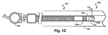
[0037] 図1C及び図1Dは、本開示によって企図される測定装置102のさらなる例を示す。具体的には、測定装置102上のセンサ106の構成及び配置が異なる。例えば、図1Cは、固体状態センサ106a(フェーズドアレイセンサとしても知られている)と回転センサ106bとを含む測定装置102を示す。図1Cの例では、測定装置102に取り付けられた駆動部材140上に回転センサ106bが配されている。センサ106は、IVUSトランスデューサ、IVUS放出器、光音響トランスデューサ及び光放出器を含むことができる。回転センサ106bは光放出器又は超音波トランスデューサを含む。いくつかの実施形態では、駆動部材140が、駆動シャフト又は可動ヒンジによって測定装置102に取り付けられている。駆動部材140は、測定装置102の長手軸に関して回転するように構成されている。いくつかの場合には、固体状態センサ106aが測定装置102に直接に取り付けられており、回転駆動部材140に対して相対的に静止したままである。いくつかの実施形態では、固体状態センサ106aが、測定装置102の周囲に円周方向に配されている。回転センサ106bは、測定装置102の周りで360°の完全な弧を描いて回転するように構成することができる。その代わりに又はそれに加えて、回転センサは、270°、180°、90°の弧又は他のさまざまな角度の弧を描いて回転するように構成される。回転センサ106bが回転する方向を、血管経路の長さに沿って変化させることができる。
[0037] FIGS. 1C and 1D illustrate additional examples of
[0038] 図1Dは、センサアレイ128を含む測定装置102を示す。図1Dの例では、センサアレイ128が、測定装置102の長手軸に関して回転するように構成されている。具体的には、センサアレイ128が、IVUSトランスデューサ、IVUS放出器、光音響トランスデューサ及び光放出器を含むセンサ及び放出器を含む。いくつかの実施形態では、センサアレイ128が、少なくとも2つの異なるタイプ又は様式のセンサを含む。例えば、センサアレイ128は、1つ又は複数の回転センサ106b、並びに第1のタイプのセンサ130及び第2のタイプのセンサ132を含む。図1Dの例では、アレイ128上に、第1及び第2のタイプのセンサ130、132が交互に配されている。いくつかの実施形態(図示せず)では、アレイ128上に、第1及び第2のタイプのセンサ130、132が、第1のタイプの個々のセンサ130が互いに隣り合わないようなチェッカー盤(checkerboard)構成で配されている。さらに、第1及び第2のタイプのセンサ130、132は、アレイ128の面積のうち大雑把に等しい割合を占めることができる。図1Cの例ではこれらのセンサが長方形又は正方形に見えるが、第1及び第2のタイプのセンサ130、132は、円形、楕円形、多角形又は他の形状を有することができる。第1及び第2のタイプのセンサ130、132は、測定装置120を横切って間隔を置いて配置することができ、又は、互いに面一に配置することもできる。いくつかの実施形態では、それぞれのタイプのセンサが、もう一方のタイプのセンサと比べてアレイ128の面積のうち大雑把に等しい割合を占める。他の実施形態では、センサアレイ128上の2つ以上のセンサタイプの表面積の比率がそれぞれ、20%及び80%、30%及び70%、又は40%及び60%である。
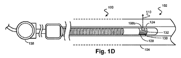
[0038] FIG. In the example of FIG. 1D,
[0039] 図1Dの例では、2つ以上の異なるタイプのセンサ130、132の列が交互に配されたセンサアレイ128が示されている。これらの列は、半径方向に配されており、測定装置102の周囲に部分的に又は完全に広がっている。いくつかの実施形態では、センサの列が、個々の列の端が互いに揃っていないような互い違いの編成で配置される。いくつかの実施形態では、センサの列が、間隔を置かずに互いに隣接して配置される。或いは、センサの列が、測定装置102を横切って間隔を置いて配置される。いくつかの場合には、測定装置102上に、2、3、4又は5列のセンサが交互に配される。上で論じたとおり、アレイ128は、測定装置102の軸を軸にして回転するように構成されている。
[0039] In the example of Figure 1D, a
[0040] 血管経路104に沿って測定装置102を移動させたときに、回転センサ106b並びに第1及び第2のタイプのセンサ130、132は、血管経路の内部の異なる区画(section)を画像化及び/又はマッピングするように動作可能である。いくつかの実施形態では、センサアレイ128の互いに反対側に位置するセンサが、個別に血管経路104の全体をマッピングし、血管経路104のマルチモードマップを生成することができるように、測定装置102を低速で移動させる。
[0040] As the
[0041] 図1Cに示されているように、センサアレイ128を、測定装置102と接触した別個の器具上に配することもできる。例えば、測定装置102と接触し、測定装置102の長手軸に関して回動する駆動部材140上に、センサアレイ128を円周方向に配することができる。
[0041] The
[0042] 本開示のシステムはさらに、米国特許仮出願(代理人整理番号IVI-0082-PRO/44755.1586PV01)、(代理人整理番号IVI-0083-PRO/44755.1587PV01)、(代理人整理番号IVI-0083-PRO/44755.1587PV01)、(代理人整理番号IVI-0088-PRO/44755.1589PV01)、及び/又は(代理人整理番号IVI-0086-PRO/44755.1592PV01)に記載された1つ又は複数の特徴を含むことができる。これらの文献はそれぞれ本出願と同日に出願されたものであり、その全体が参照によって本明細書に組み込まれている。 [0042] The system of the present disclosure further includes US provisional patent applications (Attorney Docket No. IVI-0082-PRO/44755.1586PV01), (Attorney Docket No. IVI-0083-PRO/44755.1587PV01), (Attorney Docket No. No. IVI-0083-PRO/44755.1587PV01), (Attorney Docket No. IVI-0088-PRO/44755.1589PV01), and/or (Attorney Docket No. IVI-0086-PRO/44755.1592PV01) One or more features may be included. Each of these documents was filed on even date herewith and is hereby incorporated by reference in its entirety.
[0043] 図2は、血管経路104及び周囲の組織210の概略斜視図であり、血管経路104内には、図1A、図1B、図1C又は図1Dに示された測定装置102などの測定装置102が配されている。いくつかの実施形態では、測定装置102が、図1A及び図1Bに示された引戻しデバイス138などの引戻しデバイス138に接続されており、引戻しデバイス138によって血管経路104内を移動する。測定装置102の周囲にはセンサアレイ128が配されている。いくつかの実施形態では、センサアレイ128が、血管経路104の壁の区画に向かって超音波信号402を半径方向に放出する複数の超音波トランスデューサを含む。超音波信号402は、血管経路104の壁から反射され、超音波エコー信号404として再び測定装置102に向かって進む。これらの超音波エコー信号404は、センサアレイ128上の超音波トランスデューサによって受信される。いくつかの場合には、通信システム250が、センサアレイ128のトランスデューサを、超音波信号402を放出し超音波エコー信号404を受信するように制御する。いくつかの実施形態では、測定装置102が血管経路104内を方向400に進むときに経路壁の区画406をマッピングすることにより血管経路104をマッピングするように、医療用感知システム100が動作可能である。
[0043] FIG. 2 is a schematic perspective view of a
[0044] センサアレイ128は、測定装置102の長手軸の周りで回転するように構成されている。図2の例では、センサアレイ128を含む測定装置102の頂部セクションを方向400に回転させる。この回転の速度及び方向は、医療手技の全体を通じて変化させることができる。例えば、測定装置が関心のエリア上で追加の診断データを得ることを可能にするために、回転の方向を何度か変更することができる。いくつかの実施形態では、測定装置102又は血管経路を保護するために、図1Bに示されたシース124などのシース124内に測定装置102のセクションが配される。
[0045] 組織内の関心のエリアに向かって光学パルス230を放出している光放出器220も示されている。いくつかの実施形態では、この関心のエリアが、血管経路104の部分並びに隣接する組織を含む。いくつかの実施形態では、光放出器220が、関心のエリアに向かって短いレーザパルスを放出するレーザ源である。光放出器220は、血管経路104の外側に配置することができる。図2の例では、光放出器220が血管経路104の外側に配されており、一連の光学パルス230を測定装置102に送る。いくつかの実施形態では、光学パルス230が、光ファイバに沿って測定装置102に送られる。光学パルス230は次いで、測定装置102上又は測定装置102内に配された放出器要素260を通して放出される。それに加えて又はその代わりに、血管経路104内に配置されるように、光放出器220を構成することもできる。この場合、光放出器220は、測定装置102上に位置する放出器要素260に接続232を介して信号を送り、放出器要素260は、関心のエリア内に光学パルス230を放出する。
[0045] A
[0046] 光学パルス230は、焦点242において組織210と相互作用し、組織210及び血管経路104の中を伝搬する一連の光音響波240を生成する。光音響波240は、測定装置102に接続されたセンサアレイ128内のセンサによって受信される。いくつかの実施形態では、血管経路を画像化及び/又はマッピングするために信号を送受信するようにセンサアレイ128が構成されている。血管経路104を画像化及び/又はマッピングするために、測定装置102を血管経路104内で移動させる。いくつかの場合には、血管壁に向かって超音波信号を送信し、反射された対応する超音波エコー信号を受信することにより光音響波240から独立して血管経路104をマッピングするように、センサアレイ128が構成されている。
[0047] 図2の例では、光放出器220が、接続236を介して通信システム250と通信する。いくつかの実施形態では、通信システム250は、図1Aの処理エンジン134、PIM114又はコンソール116である。通信システム250は、接続234を介して測定装置102にも接続されている。さらに、測定装置102は、接続232を介して光放出器220と直接に通信する。いくつかの実施形態では、接続232、234及び236が、電子信号又は光学信号を送信することができるケーブルである。さらに、接続232をマイクロケーブル、接続234を光ファイバ、接続236を、Bluetooth(登録商標)又はWiFi(登録商標)接続などの無線接続とすることができる。さらに、光放出器220は、無線信号受信器を含むことができる。接続234はさらに、センサアレイ128を含む測定デバイス102に電力を供給するように動作することができる。
[0047] In the example of FIG. In some embodiments,
[0048] 図2をさらに参照すると、通信システム250は、光学パルス230の放出とセンサアレイ128による光音響信号の受信とを同期させる信号を送ることによって、光放出器220及びセンサアレイ128のセンサの動作を調整する。いくつかの場合には、通信システム250が、センサアレイ128上の異なるセンサタイプの動作を調整する。具体的には、通信システム250は、センサアレイ128上の超音波様式と光音響様式との間で切り換わる。一度に1つのタイプのセンサだけを動作させると、ノイズが除去され、血管経路がより正確にマッピングされる。
[0048] Still referring to FIG. 2, the
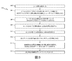
[0049] 図3は、光音響様式とIVUS様式の両方を使用して関心のエリアをマッピングする方法300を示す流れ図である。方法300のステップの前、間及び後にステップを追加することができること、並びにこの方法の他の実施形態のために、記載されたステップのうちの一部のステップを置き換え又は排除することができることが理解される。具体的には、ステップ304、306、308、310及び312を同時に実行すること、又は後に論じるようにこれらのステップをさまざまな順序で実行することができる。
[0049] Figure 3 is a flow diagram illustrating a
[0050] ステップ302で、方法300は、レーザ源を起動することを含むことができる。このレーザ源は、図2の光放出器220とすることができる。いくつかの実施形態では、レーザ源が外部に配されており、血管経路内の測定デバイス上に配されたレーザ放出器と通信する。この場合、外部レーザ源は、光ファイバなどの通信デバイスを通して測定デバイスにレーザパルスを送信する。いくつかの場合には、通信システム250が、電子信号又は光学信号によってこのレーザ源を起動する。この信号は無線で送ることができ、外部レーザ源は、無線信号受信器を備えることができる。或いは、測定デバイス上又は測定デバイス内に配されたトランスデューサアレイ上にレーザ源が含まれる。
[0050] At
[0051] ステップ304で、方法300は、2つ以上のタイプのセンサを含むセンサアレイを備える測定デバイスを有する関心領域内の組織上にレーザパルスを集束させることを含むことができる。いくつかの実施形態では、この関心領域が、少なくとも1つの血管経路104の一部分を含む組織の一部分を含む。この測定デバイスは血管経路104内に配される。関心領域は、その組織の疑わしい問題若しくは診断された問題に基づいて、又は組織の1つの領域が血管経路104内の問題に近いことに基づいて選択することができる。他の実施形態では、関心領域が、より全体的なマッピング計画の部分である。例えば、血管経路104の1つの区画のマッピング計画は、血管経路104の長さに沿って血管経路104を取り巻く組織のマッピングを含む。放出されたレーザパルスと関心領域内の組織との相互作用は、組織から放散するいくつかの光音響波240を生成する。
[0051] At
[0052] いくつかの実施形態では、測定デバイスは、図1A、図1B、図1C、図1D及び図2に示された測定装置102である。いくつかの実施形態では、トランスデューサアレイは、図1A、図1B、図1C、図1D及び図2に示されたセンサアレイ128である。トランスデューサアレイは、IVUSトランスデューサ、光音響トランスデューサ、光放出器及び光学受信器を含む1つ又は複数のセンサ及び放出器を含む。図1A、図1B、図1C、図1D及び図2に示されたいずれの例でも2つ以上のトランスデューサ要素を配列することができる。いくつかの実施形態では、トランスデューサアレイが、血管経路104内を移動するときに回転しない固体状態アレイ又はフェーズドアレイである。他の実施形態では、トランスデューサアレイが、測定デバイスの回動部分上に配された回転アレイである。いくつかの実施形態では、トランスデューサアレイが、測定デバイスの周囲に円周方向に配されている。放出されたレーザパルスと関心領域内の組織との相互作用は、組織から放散するいくつかの光音響波240を生成する。
[0052] In some embodiments, the measurement device is the
[0053] ステップ306で、方法300は、レーザパルスと組織との相互作用によって生成された音波をセンサを用いて受信することを含むことができる。いくつかの場合には、センサが、従来のIVUS機能を用いて超音波を受信するように機能することができる。他の場合には、一部又は全部のセンサが、光音響波を受信するためだけの専用のセンサである。いくつかの実施形態では、センサが、図2に示された通信システム250のような通信システム250によって制御される。別の実施形態では、処理エンジン134又はPIM114が、センサアレイ128のセンサの動作を制御する。処理エンジン134又はPIM114からセンサにコネクタ234を介して信号が送られ、それによって、センサは、音波、超音波信号及び超音波エコー信号などの診断情報を受信する。
[0053] At
[0054] ステップ308で、方法300は、少なくとも1つのトランスデューサ要素を用いて血管経路104内へ超音波信号を送信することを含むことができる。いくつかの実施形態では、ステップ308の少なくとも1つのトランスデューサが超音波送信器である。超音波信号は、1つ又は複数の送信器から血管経路104の壁に向かって送信される。送信された超音波信号は、血管経路104の壁から偏向され、超音波エコー信号として血管経路104を通って伝搬する。
[0054] At
[0055] ステップ310で、方法300は、センサを用いて血管経路104内へ超音波信号を送信することを含むことができる。血管経路104の壁に向かって超音波信号が送信され、血管経路104の壁から偏向され、超音波エコー信号として血管経路104を通って伝搬する。
[0055] At
[0056] 方法300の中で、ステップ304、306、308及び310を調整することができ、医療手技の所望の成果に基づくさまざまな順序でこれらのステップを実行することができる。例えば、超音波信号の送信及び超音波エコー信号の受信を、方法300の全体を通じて一定の間隔で実行し、同時に、光音響波の受信を散発的に実施することができる。これは、血管経路104をマッピングし、血管経路104の区画を取り巻く組織の病気にかかったエリアを抜き取り検査する医療手技で実施されることがある。或いは、ステップ304、306、308及び310は逐次的に実行される。例えば、信号ノイズを回避し、十分な信号処理を可能にするため、次のステップに進む前に、ステップ304、306、308及び310を逐次的に実行する。これは、センサアレイ内に光音響センサ及び超音波トランスデューサがそれぞれ含まれるシステムで方法300が使用されるときに有用である。さらに、方法300のステップは、さまざまな順序で交互に実施することができる。
[0056] Within
[0057] ステップ312で、方法300は、測定デバイスの長手軸に関してセンサアレイを回転させることを含むことができる。測定デバイスが血管経路の中で引っ張られたときに測定デバイスが血管経路を絶えずマッピングする場合など、いくつかの実施形態では、ステップ304、306、308及び310の全体を通じてセンサアレイを回転させる。他の実施形態では、ステップ304、306、308及び310の間、センサアレイを静止した状態に保ち、次いで、これらのステップを再び実行する前にセンサアレイを回転させる。センサアレイの回転は、測定デバイスに接続された駆動部材を使用することによって達成することができる。図1Cの例など、いくつかの実施形態では、センサアレイの部分を測定デバイスの長手軸の周りで回転させ、センサアレイの他の部分は回転させない。このセンサアレイの回転では、回転の方向及び速度を変化させることができる。例えば、センサアレイを、時計回り方向に180°回転させ、且つ/又は逆時計回り方向に180°回転させる。90°、270°、360°及びその他の角度のそれぞれの方向の回転も企図される。
[0057] At
[0058] ステップ314で、方法300は、血管経路104及び周囲の組織を含む関心領域の画像を、音波及び超音波エコー信号に基づいて生成することを含むことができる。いくつかの実施形態では、トランスデューサアレイと通信する(図1Aの処理エンジン134などの)処理エンジンが、関心領域の画像を生成する。この画像は、受信したセンサデータに基づく2次元画像と3次元画像の両方を含むことができる。いくつかの場合には、この画像が、血管経路104及び周囲の組織のいくつかの2次元断面を含む。
[0058] At
[0059] ステップ316で、方法300は、関心領域の画像をディスプレイ118に出力することを含む。このディスプレイ118は、コンピュータモニタ、患者インタフェースモジュール114(PIM)若しくはコンソール116上のスクリーン、又は画像を受信及び表示するのに適した他のデバイスを含むことができる。
At
[0060] 本開示の範囲に含まれる例示的な実施形態では、ステップ316の後に方法300を、方法の流れがステップ304に戻り、再開されるように繰り返す。方法300の繰返しを利用して、血管経路及び周囲の組織をマッピングする。
[0060] In an exemplary embodiment within the scope of this disclosure, after
[0061] 上で説明した装置、システム及び方法をさまざまなやり方で変更することができることを当業者は認識する。したがって、本開示が包含する実施形態は、上で説明した例示的な特定の実施形態だけに限定されないことを当業者は理解する。この点に関して、例示的な実施形態を示し、説明してきたが、上記の開示では、広範囲の変更、改変及び置換が企図される。本開示の範囲から逸脱することなく上記の開示にこのような変形を実施することができることが理解される。したがって、添付の特許請求項は、本開示と矛盾しない形で広く解釈されることが理解される。 [0061] Those skilled in the art will recognize that the apparatus, systems and methods described above can be modified in various ways. Accordingly, those skilled in the art will appreciate that the embodiments encompassed by this disclosure are not limited to only the specific exemplary embodiments described above. In this regard, while exemplary embodiments have been shown and described, the above disclosure contemplates a wide range of alterations, modifications, and substitutions. It is understood that such variations can be made to the above disclosure without departing from the scope of the present disclosure. It is therefore to be understood that the appended claims are to be interpreted broadly in a manner consistent with this disclosure.
Claims (9)
前記細長い本体の長さに沿って延び、前記細長い本体に対して回転可能である回転駆動部材と、
前記回転駆動部材の遠位部分に結合された光放出器であって、関心領域内の組織に光学パルスを放出する前記光放出器と、
を備える、医療用感知デバイスであって、前記超音波トランスデューサは、
前記光学パルスと組織との相互作用の結果として組織によって生成された音波を受信し、
超音波信号を送信し、
送信された超音波信号に基づく超音波エコー信号を受信する、医療用感知デバイス。 a measuring device comprising an elongated body sized and shaped for insertion into a vascular pathway, the elongated body having an ultrasound transducer stationary relative to the elongated body;
a rotary drive member extending along the length of the elongate body and rotatable relative to the elongate body;
a light emitter coupled to a distal portion of the rotary drive member for emitting optical pulses into tissue within a region of interest;
A medical sensing device comprising:
receiving acoustic waves produced by tissue as a result of interaction of said optical pulse with tissue;
transmit an ultrasonic signal,
A medical sensing device that receives ultrasonic echo signals based on transmitted ultrasonic signals.
を備える、医療用感知システムであって、
前記光放出器は、前記回転駆動部材の遠位部分に結合され、前記光源から受信した光学パルスを関心領域内の組織に放出する、医療用感知システム。 A medical sensing system comprising a medical sensing device according to any one of claims 1 to 6 , further comprising a light source for emitting optical pulses,
A medical sensing system, wherein the light emitter is coupled to a distal portion of the rotary drive member and emits optical pulses received from the light source into tissue within a region of interest.
Applications Claiming Priority (3)
| Application Number | Priority Date | Filing Date | Title |
|---|---|---|---|
| US201662315251P | 2016-03-30 | 2016-03-30 | |
| US62/315,251 | 2016-03-30 | ||
| PCT/IB2017/051679 WO2017168289A1 (en) | 2016-03-30 | 2017-03-23 | Rotational intravascular devices, systems, and methods utilizing photoacoustic and ultrasound imaging techniques |
Publications (3)
| Publication Number | Publication Date |
|---|---|
| JP2019509861A JP2019509861A (en) | 2019-04-11 |
| JP2019509861A5 JP2019509861A5 (en) | 2020-04-30 |
| JP7132850B2 true JP7132850B2 (en) | 2022-09-07 |
Family
ID=58448588
Family Applications (1)
| Application Number | Title | Priority Date | Filing Date |
|---|---|---|---|
| JP2018551410A Active JP7132850B2 (en) | 2016-03-30 | 2017-03-23 | Rotating intravascular devices, systems and methods utilizing photoacoustic and ultrasound imaging techniques |
Country Status (4)
| Country | Link |
|---|---|
| US (1) | US11559207B2 (en) |
| EP (1) | EP3435841A1 (en) |
| JP (1) | JP7132850B2 (en) |
| WO (1) | WO2017168289A1 (en) |
Families Citing this family (2)
| Publication number | Priority date | Publication date | Assignee | Title |
|---|---|---|---|---|
| WO2020113083A1 (en) | 2018-11-28 | 2020-06-04 | Histosonics, Inc. | Histotripsy systems and methods |
| CA3169465A1 (en) | 2020-01-28 | 2021-08-05 | The Regents Of The University Of Michigan | Systems and methods for histotripsy immunosensitization |
Citations (6)
| Publication number | Priority date | Publication date | Assignee | Title |
|---|---|---|---|---|
| JP2011516865A (en) | 2008-04-03 | 2011-05-26 | インフラレドックス インコーポレーティッド | System and method for intravascular structure analysis correcting chemical analysis modalities |
| JP2012514522A (en) | 2009-01-09 | 2012-06-28 | ボストン サイエンティフィック サイムド,インコーポレイテッド | System and method for creating and using an intravascular ultrasound system having photoacoustic imaging capabilities |
| JP2013022171A (en) | 2011-07-20 | 2013-02-04 | Fujifilm Corp | Catheter type photoacoustic probe |
| JP2013027482A (en) | 2011-07-27 | 2013-02-07 | Fujifilm Corp | Catheter type photoacoustic probe and photoacoustic imaging device provided with the same |
| US20130338498A1 (en) | 2009-11-02 | 2013-12-19 | Board Of Regents, The University Of Texas System | Catheter for Intravascular Ultrasound and Photoacoustic Imaging |
| US20140221842A1 (en) | 2013-02-01 | 2014-08-07 | Robin F. Castelino | System and Method for Frequency Domain Photoacoustic Intravascular Imaging |
Family Cites Families (8)
| Publication number | Priority date | Publication date | Assignee | Title |
|---|---|---|---|---|
| US5243988A (en) | 1991-03-13 | 1993-09-14 | Scimed Life Systems, Inc. | Intravascular imaging apparatus and methods for use and manufacture |
| DE69333482T2 (en) | 1992-02-21 | 2005-03-24 | Boston Scientific Ltd., Barbados | Catheter for imaging by means of ultrasound |
| US7226417B1 (en) | 1995-12-26 | 2007-06-05 | Volcano Corporation | High resolution intravascular ultrasound transducer assembly having a flexible substrate |
| US8104479B2 (en) | 2005-06-23 | 2012-01-31 | Volcano Corporation | Pleated bag for interventional pullback systems |
| WO2010080991A2 (en) * | 2009-01-09 | 2010-07-15 | Washington University In St. Louis | Miniaturized photoacoustic imaging apparatus including a rotatable reflector |
| EP2671093B1 (en) * | 2011-01-31 | 2019-01-16 | Sunnybrook Health Sciences Centre | Ultrasonic probe with ultrasonic transducers addressable on common electrical channel |
| US9295447B2 (en) | 2011-08-17 | 2016-03-29 | Volcano Corporation | Systems and methods for identifying vascular borders |
| WO2014100207A1 (en) * | 2012-12-21 | 2014-06-26 | Paul Hoseit | Imaging guidewire with photoactivation capabilities |
-
2017
- 2017-03-23 EP EP17714301.3A patent/EP3435841A1/en not_active Withdrawn
- 2017-03-23 US US16/088,104 patent/US11559207B2/en active Active
- 2017-03-23 JP JP2018551410A patent/JP7132850B2/en active Active
- 2017-03-23 WO PCT/IB2017/051679 patent/WO2017168289A1/en active Application Filing
Patent Citations (6)
| Publication number | Priority date | Publication date | Assignee | Title |
|---|---|---|---|---|
| JP2011516865A (en) | 2008-04-03 | 2011-05-26 | インフラレドックス インコーポレーティッド | System and method for intravascular structure analysis correcting chemical analysis modalities |
| JP2012514522A (en) | 2009-01-09 | 2012-06-28 | ボストン サイエンティフィック サイムド,インコーポレイテッド | System and method for creating and using an intravascular ultrasound system having photoacoustic imaging capabilities |
| US20130338498A1 (en) | 2009-11-02 | 2013-12-19 | Board Of Regents, The University Of Texas System | Catheter for Intravascular Ultrasound and Photoacoustic Imaging |
| JP2013022171A (en) | 2011-07-20 | 2013-02-04 | Fujifilm Corp | Catheter type photoacoustic probe |
| JP2013027482A (en) | 2011-07-27 | 2013-02-07 | Fujifilm Corp | Catheter type photoacoustic probe and photoacoustic imaging device provided with the same |
| US20140221842A1 (en) | 2013-02-01 | 2014-08-07 | Robin F. Castelino | System and Method for Frequency Domain Photoacoustic Intravascular Imaging |
Also Published As
| Publication number | Publication date |
|---|---|
| EP3435841A1 (en) | 2019-02-06 |
| US20200297214A1 (en) | 2020-09-24 |
| WO2017168289A1 (en) | 2017-10-05 |
| JP2019509861A (en) | 2019-04-11 |
| US11559207B2 (en) | 2023-01-24 |
Similar Documents
| Publication | Publication Date | Title |
|---|---|---|
| US20230293149A1 (en) | Phased array intravascular devices, systems, and methods utilizing photoacoustic and ultrasound techniques` | |
| EP3435877B1 (en) | Intravascular devices, systems, and methods utilizing photoacoustic, ultrasound, and optical coherence tomography imaging techniques | |
| JP7304344B2 (en) | Wireless Digital Patient Interface Module with Wireless Charging | |
| JP7194733B2 (en) | Digital Rotation Patient Interface Module | |
| US20140163361A1 (en) | Combination Rotational and Phased-Array In Vivo Imaging Devices and Methods | |
| JP7132850B2 (en) | Rotating intravascular devices, systems and methods utilizing photoacoustic and ultrasound imaging techniques | |
| JP6932085B2 (en) | Multimode Capacitive Micromachine Ultrasonic Transducers and Related Devices, Systems and Methods | |
| US20230218266A1 (en) | Tissue and vascular pathway mapping using synchronized photoacoustic and ultrasound pullback techniques | |
| EP3435876B1 (en) | Tissue and vascular pathway mapping utilizing photoacoustic and ultrasound techniques | |
| US11819360B2 (en) | Intraluminal rotational ultrasound for diagnostic imaging and therapy | |
| JP2020512145A (en) | Intravascular ultrasound patient interface module (PIM) for distributed wireless intraluminal imaging system |
Legal Events
| Date | Code | Title | Description |
|---|---|---|---|
| A521 | Request for written amendment filed |
Free format text: JAPANESE INTERMEDIATE CODE: A523 Effective date: 20200319 |
|
| A621 | Written request for application examination |
Free format text: JAPANESE INTERMEDIATE CODE: A621 Effective date: 20200319 |
|
| A977 | Report on retrieval |
Free format text: JAPANESE INTERMEDIATE CODE: A971007 Effective date: 20210129 |
|
| A131 | Notification of reasons for refusal |
Free format text: JAPANESE INTERMEDIATE CODE: A131 Effective date: 20210222 |
|
| A601 | Written request for extension of time |
Free format text: JAPANESE INTERMEDIATE CODE: A601 Effective date: 20210521 |
|
| A521 | Request for written amendment filed |
Free format text: JAPANESE INTERMEDIATE CODE: A523 Effective date: 20210816 |
|
| A131 | Notification of reasons for refusal |
Free format text: JAPANESE INTERMEDIATE CODE: A131 Effective date: 20220105 |
|
| A521 | Request for written amendment filed |
Free format text: JAPANESE INTERMEDIATE CODE: A523 Effective date: 20220331 |
|
| TRDD | Decision of grant or rejection written | ||
| A01 | Written decision to grant a patent or to grant a registration (utility model) |
Free format text: JAPANESE INTERMEDIATE CODE: A01 Effective date: 20220729 |
|
| A61 | First payment of annual fees (during grant procedure) |
Free format text: JAPANESE INTERMEDIATE CODE: A61 Effective date: 20220826 |
|
| R150 | Certificate of patent or registration of utility model |
Ref document number: 7132850 Country of ref document: JP Free format text: JAPANESE INTERMEDIATE CODE: R150 |