JP7126838B2 - Support structures, support cradles and photovoltaic installations - Google Patents
Support structures, support cradles and photovoltaic installations Download PDFInfo
- Publication number
- JP7126838B2 JP7126838B2 JP2018049560A JP2018049560A JP7126838B2 JP 7126838 B2 JP7126838 B2 JP 7126838B2 JP 2018049560 A JP2018049560 A JP 2018049560A JP 2018049560 A JP2018049560 A JP 2018049560A JP 7126838 B2 JP7126838 B2 JP 7126838B2
- Authority
- JP
- Japan
- Prior art keywords
- support
- crosspiece
- vertical
- horizontal
- screw
- Prior art date
- Legal status (The legal status is an assumption and is not a legal conclusion. Google has not performed a legal analysis and makes no representation as to the accuracy of the status listed.)
- Active
Links
Images


Classifications
-
- Y—GENERAL TAGGING OF NEW TECHNOLOGICAL DEVELOPMENTS; GENERAL TAGGING OF CROSS-SECTIONAL TECHNOLOGIES SPANNING OVER SEVERAL SECTIONS OF THE IPC; TECHNICAL SUBJECTS COVERED BY FORMER USPC CROSS-REFERENCE ART COLLECTIONS [XRACs] AND DIGESTS
- Y02—TECHNOLOGIES OR APPLICATIONS FOR MITIGATION OR ADAPTATION AGAINST CLIMATE CHANGE
- Y02B—CLIMATE CHANGE MITIGATION TECHNOLOGIES RELATED TO BUILDINGS, e.g. HOUSING, HOUSE APPLIANCES OR RELATED END-USER APPLICATIONS
- Y02B10/00—Integration of renewable energy sources in buildings
- Y02B10/10—Photovoltaic [PV]
-
- Y—GENERAL TAGGING OF NEW TECHNOLOGICAL DEVELOPMENTS; GENERAL TAGGING OF CROSS-SECTIONAL TECHNOLOGIES SPANNING OVER SEVERAL SECTIONS OF THE IPC; TECHNICAL SUBJECTS COVERED BY FORMER USPC CROSS-REFERENCE ART COLLECTIONS [XRACs] AND DIGESTS
- Y02—TECHNOLOGIES OR APPLICATIONS FOR MITIGATION OR ADAPTATION AGAINST CLIMATE CHANGE
- Y02E—REDUCTION OF GREENHOUSE GAS [GHG] EMISSIONS, RELATED TO ENERGY GENERATION, TRANSMISSION OR DISTRIBUTION
- Y02E10/00—Energy generation through renewable energy sources
- Y02E10/50—Photovoltaic [PV] energy
Landscapes
- Roof Covering Using Slabs Or Stiff Sheets (AREA)
Description
本発明は、所定の支持対象物を支持するための支持構造、そのような支持構造を有する支持架台、及び太陽光発電設備に関する。 TECHNICAL FIELD The present invention relates to a support structure for supporting a given support object, a support frame having such a support structure, and a photovoltaic power generation facility.
地球環境問題に対する関心の高まりを受けて、温室効果ガスの削減等に効果が期待される太陽光発電が注目されている。太陽光発電設備において太陽電池パネルを支持するための支持構造が以前より種々知られている(例えば、特許文献1参照。)。 With growing interest in global environmental problems, photovoltaic power generation, which is expected to be effective in reducing greenhouse gases, is attracting attention. BACKGROUND ART Various support structures for supporting solar cell panels in photovoltaic power generation facilities have been known for some time (see, for example, Patent Document 1).
ここで、上記のような支持構造を設置する際には、設置場所における正確な位置出しや、場合によっては大規模な造成工事等を要することがあり、設置作業の手間の点でもコストの点でも負担となっているのが現状である。 Here, when installing the support structure as described above, it may be necessary to accurately locate the installation site, and in some cases, large-scale construction work, etc. However, the current situation is that it is a burden.
また、ここでは、太陽光発電設備における支持構造を例に挙げて、設置作業の手間やコストにおける負担について説明した。しかしながら、このような負担は、太陽電池パネルのための支持構造に限るものではなく、所定の支持対象物を支持するための支持構造について一般的に生じ得る。 In addition, here, the support structure in the photovoltaic power generation equipment was taken as an example to explain the labor and cost burden of the installation work. However, such a burden is not limited to the support structure for the solar cell panel, and can generally occur for the support structure for supporting a given support object.
従って、本発明は、上記のような課題に着目し、手間やコストの負担を抑えて設置することができる支持構造、そのような支持構造を有する支持架台、及び太陽光発電設備を提供することを目的とする。 Therefore, the present invention focuses on the above problems, and provides a support structure that can be installed with reduced labor and cost burden, a support frame having such a support structure, and a photovoltaic power generation facility. With the goal.
上記課題を解決するために、本発明の支持構造は、所定の基礎構造の上に、格子状に組まれ、所定の支持対象物を支持するための支持構造であって、第1方向に延在するとともに、当該第1方向と交差する第2方向に複数本が並ぶように、前記基礎構造に連結される第1桟材と、前記第2方向に延在するとともに前記第1方向に複数本が並ぶように、前記第1桟材に連結される第2桟材と、前記基礎構造において、複数本の前記第1桟材が連結される複数の位置に取付けられるとともに各前記第1桟材が第1ネジによって固定されることで、各位置における前記第1桟材の連結を中継する第1支持金具と、複数本の前記第1桟材において、複数本の前記第2桟材が連結される複数の位置に取付けられるとともに各前記第2桟材が第2ネジによって固定されることで、各位置における前記第2桟材の連結を中継する第2支持金具と、を備え、複数本の前記第1桟材における、前記第1支持金具を介した前記基礎構造との複数の第1連結箇所のうち少なくとも1つには、前記第1方向に延びた第1長孔が前記第1ネジを通すために設けられ、複数本の前記第2桟材における、前記第2支持金具を介した複数本の前記第1桟材との複数の第2連結箇所のうち少なくとも1つには、前記第2方向に延びた第2長孔が前記第2ネジを通すために設けられており、前記第1長孔が、前記第1桟材において上下方向に延在する側面壁に設けられ、前記第2長孔が、前記第2桟材において上下方向に延在する側面壁に設けられており、前記第1桟材には、当該第1桟材の上面壁及び前記第1長孔と交差して延在する第1帯状部材が被せられ、前記第2桟材には、当該第2桟材の上面壁及び前記第2長孔と交差して延在する第2帯状部材が被せられ、前記第1ネジは、前記第1帯状部材を貫通して前記第1長孔に通され、前記第2ネジは、前記第2帯状部材を貫通して前記第2長孔に通されることを特徴とする。 In order to solve the above problems, the support structure of the present invention is a support structure assembled in a grid pattern on a predetermined base structure for supporting a predetermined support object, the support structure extending in a first direction. a first crosspiece member connected to the basic structure such that a plurality of crosspiece members are arranged in a second direction intersecting the first direction; A second crosspiece connected to the first crosspiece so that a plurality of crosspieces are aligned; By fixing one crosspiece with a first screw, a first support fitting that relays the connection of the first crosspiece at each position, and a plurality of the second crosspieces in the plurality of first crosspieces. a second support fitting that is attached to a plurality of positions where the members are connected and that each of the second crosspieces is fixed by a second screw to relay the connection of the second crosspieces at each position; , at least one of a plurality of first connection points of the plurality of first crosspieces to the base structure via the first support metal fitting has a first elongated hole extending in the first direction. At least one of a plurality of second connection points provided for passing the first screws through the plurality of second crosspiece members and the plurality of first crosspiece members via the second support metal fittings. is provided with a second elongated hole extending in the second direction for passing the second screw, and the first elongated hole is formed in a side wall extending in the vertical direction of the first cross member. The second elongated hole is provided in a side wall extending in the vertical direction of the second crosspiece, and the first crosspiece has an upper surface wall of the first crosspiece and the first crosspiece. A first strip member extending across the long hole is covered, and the second rail member is covered with a second strip member extending across the top wall of the second rail member and the second long hole. The first screw passes through the first strip-shaped member and passes through the first long hole, and the second screw passes through the second strip-shaped member and passes through the second long hole. characterized by being
本発明の支持構造によれば、第1桟材における少なくとも1つの第1連結箇所については第1長孔の長さ分の自由度を以て基礎構造に取り付けられる。同様に、第2桟材における少なくとも1つの第2連結箇所についても第2長孔の長さ分の自由度を以て第1桟材に取り付けられる。これにより、設置に際して、基礎構造における第1桟材の取付け位置や、第1桟材における第2桟材の取付け位置についての位置出しの精度をある程度緩めても第1長孔や第2長孔である程度の位置ズレを吸収することができる。このため、本発明の支持構造によれば、手間やコストの負担を抑えて設置することができる。 According to the support structure of the present invention, at least one first connection point of the first cross member is attached to the foundation structure with a degree of freedom corresponding to the length of the first elongated hole. Similarly, at least one second connection point on the second crosspiece is also attached to the first crosspiece with a degree of freedom corresponding to the length of the second long hole. As a result, when installing the first long hole and the second long hole even if the positioning accuracy of the mounting position of the first crosspiece in the basic structure and the mounting position of the second crosspiece in the first crosspiece is loosened to some extent. can absorb a certain amount of positional deviation. For this reason, according to the support structure of the present invention, it is possible to install with reduced labor and costs.
ここで、本発明の支持構造において、前記複数の第1連結箇所のうち少なくとも1つに前記第1ネジを通すための丸孔が位置決め用基準孔として設けられ、他の全ての箇所に前記第1長孔が設けられており、前記複数の第2連結箇所の全てに前記第2長孔が設けられていることが好適である。 Here, in the support structure of the present invention, at least one of the plurality of first connection locations is provided with a round hole as a positioning reference hole for passing the first screw, and all other locations are provided with the above-mentioned second screws. It is preferable that one elongated hole is provided, and that the second elongated holes are provided in all of the plurality of second connection locations.
この好適な支持構造によれば、第1ネジや第2ネジを通す孔の殆どを長孔にして取付の自由度を高めつつも、基礎構造側となる第1桟材に位置決め用基準孔を設けておくことで、基礎構造に対する支持構造全体の取付け位置を確定することができる。 According to this preferred support structure, most of the holes through which the first screws and the second screws are passed are elongated to increase the degree of mounting freedom, and at the same time, positioning reference holes are provided in the first cross member on the side of the base structure. By providing it, it is possible to determine the mounting position of the entire support structure with respect to the foundation structure.
また、複数本の前記第1桟材のうち前記位置決め用基準孔が設けられた基準桟材が、他の前記第1桟材とは異なる外形に形成されていることが更に好適である。 Further, it is more preferable that, among the plurality of first crosspieces, the reference crosspiece provided with the positioning reference hole is formed in an outer shape different from that of the other first crosspieces.
この更に好適な支持構造によれば、設置に際して、作業者が基準桟材を容易に識別することができるので、手間やコストの負担を抑えて設置することができる。 According to this more preferable support structure, the operator can easily identify the reference crosspiece during installation, so that the installation can be performed with reduced labor and cost.
また、本発明の支持構造において、複数の前記第2桟材と交差するように延在し、複数の前記第2桟材が所定間隔で互いに平行に、且つ、前記第1桟材と直交して並ぶように各前記第2桟材の位置を規制した状態で各前記第2桟材に固定された規制部材を備えたことも好適である。 Further, in the support structure of the present invention, the plurality of second crosspieces extend so as to intersect with the plurality of second crosspieces, and the plurality of second crosspieces are parallel to each other at predetermined intervals and perpendicular to the first crosspieces. It is also preferable to provide a regulating member fixed to each of the second crosspieces in a state where the positions of the second crosspieces are regulated so that the second crosspieces are aligned.
この好適な支持構造によれば、設置に際して、複数の第2桟材に上記の規制部材を取付けることで、これら複数の第2桟材の相対的な位置出しを行うことができ、その後の第2桟材に対する支持対象物の取付けを容易に行なうことができる。その上で、この規制部材が位置出し後も補強部材として残るので、支持構造の強度を向上させることもできる。 According to this preferred support structure, when installing, by attaching the regulating member to the plurality of second crosspieces, it is possible to perform relative positioning of the plurality of second crosspieces. The object to be supported can be easily attached to the two crosspieces. In addition, since the restricting member remains as a reinforcing member even after positioning, the strength of the support structure can be improved.
また、本発明の支持構造において、前記第1長孔が、前記第1桟材において上下方向に延在する側面壁に設けられ、前記第2長孔が、前記第2桟材において上下方向に延在する側面壁に設けられており、前記第1桟材には、当該第1桟材の上面壁及び前記第1長孔と交差して延在する第1帯状部材が被せられ、前記第2桟材には、当該第2桟材の上面壁及び前記第2長孔と交差して延在する第2帯状部材が被せられ、前記第1ネジは、前記第1帯状部材を貫通して前記第1長孔に通され、前記第2ネジは、前記第2帯状部材を貫通して前記第2長孔に通されることも好適である。 Further, in the support structure of the present invention, the first long hole is provided in a side wall extending vertically in the first crosspiece, and the second long hole is provided in the second crosspiece in the vertical direction. A first belt-shaped member is provided on the extending side wall, and the first crosspiece member is covered with a first belt-shaped member extending across the upper surface wall of the first crosspiece member and the first elongated hole. The second rail member is covered with a second belt-shaped member extending across the upper surface wall of the second rail member and the second elongated hole, and the first screw passes through the first belt-shaped member. It is also preferable that the second screw is passed through the first elongated hole and passed through the second elongated hole through the second belt-like member.
この好適な支持構造によれば、例えば支持構造の設置中や設置後に第1桟材や第2桟材を上方に持上げるような力が加わったときに、その力が、上記の第1帯状部材や第2帯状部材で受け止められることとなる。これにより、このような力が第1長孔や第2長孔の周辺部分に及ぼす負荷を抑制することができる。 According to this preferred support structure, for example, when a force is applied during or after installation of the support structure to lift the first crosspiece or the second crosspiece, the force is applied to the first band-like shape. It will be received by the member or the second belt-like member. As a result, the load exerted by such force on the peripheral portions of the first elongated hole and the second elongated hole can be suppressed.
また、本発明の支持構造において、前記第2桟材は、複数の前記支持対象物が並べられて載置されるものであり、前記第2桟材において、前記支持対象物の境界となる位置には、耐食性の表面処理が施されたカバー部材が、当該第2桟材と前記支持対象物との間に挟まれるように配置されていることが好適である。 Further, in the support structure of the present invention, the second crosspiece is for placing a plurality of the objects to be supported side by side. Preferably, a cover member subjected to a corrosion-resistant surface treatment is arranged so as to be sandwiched between the second cross member and the support object.
この好適な支持構造によれば、例えば支持対象物の境界を第2桟材まで伝い落ちた雨水等が、耐食性の表面処理が施されたカバー部材で受け止められるので、設置後の第2桟材の寿命を延ばすことができる。 According to this preferred support structure, for example, rainwater or the like that runs along the boundary of the object to be supported down to the second crosspiece can be received by the cover member that has been subjected to a corrosion-resistant surface treatment. can extend the life of
また、本発明の支持構造において、前記基礎構造における、前記複数の第1連結箇所と対応した複数の位置に取付けられた第1支持金具と、複数本の前記第1桟材における、前記複数の第2連結箇所と対応した複数の位置に取付けられた第2支持金具と、を備え、前記第1桟材が、前記第1ネジによって前記第1支持金具に固定され、前記第2桟材が、前記第2ネジによって前記第2支持金具に固定されることも好適である。 Further, in the support structure of the present invention, the first support metal fittings attached at a plurality of positions corresponding to the plurality of first connection points in the base structure, and the plurality of a second support bracket attached at a plurality of positions corresponding to the second connection points, wherein the first rail is fixed to the first support bracket by the first screw, and the second rail is , and is preferably fixed to the second support fitting by the second screw.
この好適な支持構造によれば、第1桟材と基礎構造との連結や、第2桟材と第1桟材との連結が、第1支持金具や第2支持金具を介して行われる。これにより、設置に際して作業者が、基礎構造における第1桟材の設置位置や第1桟材における第2桟材の設置位置を把握し易い。即ち、この好適な支持構造によれば、手間やコストの負担を一層抑えて設置することができる。 According to this preferred support structure, the connection between the first crosspiece and the basic structure and the connection between the second crosspiece and the first crosspiece are performed via the first support metal fittings and the second support metal fittings. This makes it easy for the operator to grasp the installation position of the first crosspiece in the basic structure and the installation position of the second crosspiece in the first crosspiece during installation. In other words, according to this preferred support structure, it is possible to install with further reduced labor and costs.
また、この好適な支持構造において、前記第1桟材は、幅方向の断面形状が前記第1支持金具を内側に収める凹形状となっており、前記第1支持金具に被せられた状態で固定され、前記第2桟材は、幅方向の断面形状が前記第2支持金具を内側に収める凹形状となっており、前記第2支持金具に被せられた状態で固定されることが更に好適である。 Further, in this preferred support structure, the first crosspiece member has a cross-sectional shape in the width direction of a concave shape that accommodates the first support metal fitting inside, and is fixed in a state of being covered with the first support metal fitting. It is further preferable that the second crosspiece member has a cross-sectional shape in the width direction that is a concave shape that accommodates the second support metal fitting inside, and that the second rail material is fixed while being covered with the second support metal fitting. be.
この好適な支持構造によれば、第1桟材の取付けに際し、作業者は、第1支持金具に被せることで安定した状態で仮置きし、その後にネジ止め作業を順次に行うことができる。同様に、第2桟材の取付けに際し、作業者は、第2支持金具に被せることで安定した状態で仮置きし、その後にネジ止め作業を順次に行うことができる。このように、この好適な支持構造によれば、手間やコストの負担を更に抑えて設置することができる。 According to this preferred support structure, when attaching the first cross member, the worker can put the first cross member temporarily in a stable state by putting it over the first support fitting, and then sequentially screw it. Similarly, when attaching the second crosspiece, the worker can place it temporarily in a stable state by putting it over the second support bracket, and then sequentially screw it. Thus, according to this preferred support structure, it is possible to further reduce the burden of labor and cost when installing.
また、本発明の支持構造において、前記第1支持金具には、前記第1桟材を、傾斜角度を調節可能に傾かせた状態で支持する第1支点突起が設けられ、前記第2支持金具には、前記第2桟材を、傾斜角度を調節可能に傾かせた状態で支持する第2支点突起が設けられており、前記第1長孔は、傾斜角度の調節時において前記第1桟材の傾斜角度によっては前記第1支点突起から前記第1桟材が離れることを許容する程度に、又は、傾斜角度の調節中は常に前記第1桟材が前記第1支点突起に接触する程度に、前記第1ネジに対して余裕を持った孔幅を有して形成され、前記第2長孔は、傾斜角度の調節時に、前記第2桟材の傾斜角度によっては前記第2支点突起から前記第2桟材が離れることを許容する程度に、又は、調節中は常に前記第2桟材が前記第2支点突起に接触する程度に、前記第2ネジに対して余裕を持った孔幅を有して形成されていることも好適である。 Further, in the support structure of the present invention, the first support metal fitting is provided with a first fulcrum projection that supports the first crosspiece member in a state in which the tilt angle is adjustable, and the second support metal fitting. is provided with a second fulcrum projection that supports the second crosspiece in an inclined state so that the inclination angle can be adjusted , and the first long hole is aligned with the first crosspiece when the inclination angle is adjusted. Depending on the inclination angle of the material, the first crosspiece is allowed to separate from the first fulcrum projection, or the first crosspiece is always in contact with the first fulcrum projection during adjustment of the inclination angle. 2, the second elongated hole is formed with a width sufficient for the first screw, and the second elongated hole is formed with the second fulcrum projection depending on the inclination angle of the second crosspiece when the inclination angle is adjusted. a hole with enough room for the second screw to allow the second rail to leave from the second screw, or to keep the second rail in contact with the second fulcrum projection at all times during adjustment. It is also suitable to have a width .
この好適な支持構造によれば、第1支点突起や第2支点突起で第1桟材や第2桟材を支持することで、第1桟材や第2桟材を容易に傾斜設置することができ、延いては、支持対象部を容易に傾斜支持することができる。 According to this preferable support structure, by supporting the first crosspiece and the second crosspiece by the first fulcrum projection and the second fulcrum projection, the first crosspiece and the second crosspiece can be easily inclined. and, by extension, it is possible to easily tilt and support the part to be supported.
また、上記課題を解決するために、本発明の支持架台は、所定の基礎構造と、前記基礎構造の上に、格子状に組まれ、所定の支持対象物を支持するための上述した本発明の支持構造と、を備えたことを特徴とする。 Further, in order to solve the above-mentioned problems, the support frame of the present invention comprises a predetermined base structure and the above-described support frame of the present invention, which is assembled in a grid pattern on the base structure and supports a predetermined object to be supported. and a support structure.
本発明の支持架台によれば、支持対象物の支持に上述した本発明の支持構造が使われることから、手間やコストの負担を抑えて設置することができる。 According to the support frame of the present invention, since the above-described support structure of the present invention is used to support the object to be supported, it is possible to install the object with less labor and cost.
また、上記課題を解決するために、本発明の太陽光発電設備は、少なくとも1枚の太陽電池パネルと、前記太陽電池パネルを支持するための上述した本発明の支持架台と、を備えたことを特徴とする。 Further, in order to solve the above problems, a solar power generation facility of the present invention includes at least one solar cell panel and the above-described support frame of the present invention for supporting the solar cell panel. characterized by
本発明の太陽光発電設備によれば、太陽電池パネルの支持に上述した本発明の支持架台が使われることから、手間やコストの負担を抑えて設置することができる。 According to the photovoltaic power generation equipment of the present invention, since the above-described support frame of the present invention is used to support the solar battery panel, it is possible to install the equipment with reduced labor and costs.
本発明の支持構造によれば、第1桟材における少なくとも1つの第1連結箇所については第1長孔の長さ分の自由度を以て基礎構造に取り付けられる。同様に、第2桟材における少なくとも1つの第2連結箇所についても第2長孔の長さ分の自由度を以て第1桟材に取り付けられる。これにより、設置に際して、基礎構造における第1桟材の取付け位置や、第1桟材における第2桟材の取付け位置についての位置出しの精度をある程度緩めても第1長孔や第2長孔である程度の位置ズレを吸収することができる。このため、本発明の支持構造によれば、手間やコストの負担を抑えて設置することができる。 According to the support structure of the present invention, at least one first connection point of the first cross member is attached to the foundation structure with a degree of freedom corresponding to the length of the first elongated hole. Similarly, at least one second connection point on the second crosspiece is also attached to the first crosspiece with a degree of freedom corresponding to the length of the second long hole. As a result, when installing the first long hole and the second long hole even if the positioning accuracy of the mounting position of the first crosspiece in the basic structure and the mounting position of the second crosspiece in the first crosspiece is loosened to some extent. can absorb a certain amount of positional deviation. For this reason, according to the support structure of the present invention, it is possible to install with reduced labor and costs.
本発明の支持架台によれば、支持対象物の支持に上述した本発明の支持構造が使われることから、手間やコストの負担を抑えて設置することができる。 According to the support frame of the present invention, since the above-described support structure of the present invention is used to support the object to be supported, it is possible to install the object with less labor and cost.
また、本発明の太陽光発電設備によれば、太陽電池パネルの支持に上述した本発明の支持架台が使われることから、手間やコストの負担を抑えて設置することができる。 In addition, according to the photovoltaic power generation equipment of the present invention, since the above-described support frame of the present invention is used to support the solar cell panel, it is possible to install the equipment with reduced labor and cost.
本発明の支持構造、支持架台、及び太陽光発電設備の一実施形態について、以下、図面を参照して説明する。 An embodiment of a support structure, a support frame, and a photovoltaic power generation system according to the present invention will be described below with reference to the drawings.
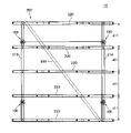
図1は、本発明の一実施形態にかかる太陽光発電設備を示す平面図である。図2は、図1に示されている太陽光発電設備を図中の矢印V11方向から見た正面図であり、図3は、図1に示されている太陽光発電設備を図中の矢印V12方向から見た背面図である。また、図4は、図1に示されている太陽光発電設備を図中の矢印V13方向から見た側面図であり、図5は、図1に示されている太陽光発電設備を図中の矢印V14方向から見た側面図である。尚、図1には、太陽電池パネル2が一点鎖線で示され、その下側の支持架台10が見えるように、太陽光発電設備1が透視図で示されている。
FIG. 1 is a plan view showing a photovoltaic power generation facility according to one embodiment of the present invention. 2 is a front view of the photovoltaic power generation facility shown in FIG. 1 as viewed from the direction of arrow V11 in the figure, and FIG. 3 is a front view of the photovoltaic power generation facility shown in FIG. It is the back view seen from V12 direction. 4 is a side view of the photovoltaic power generation facility shown in FIG. 1 as viewed from the direction of arrow V13 in the figure, and FIG. 5 is a side view of the photovoltaic power generation facility shown in FIG. is a side view seen from the direction of an arrow V14. In addition, in FIG. 1, the
本実施形態の太陽光発電設備1は、設置場所として屋外の大地A11に設置された支持架台10で、各々が長方形の12枚の太陽電池パネル2を4行×3列に配列して支持したものである。以下、太陽電池パネル2の長辺に沿った方向をX軸方向、短辺に沿った方向をY軸方向、大地A11に対する鉛直方向をZ軸方向と呼んで説明する。図1~図5には、各々、X軸方向、Y軸方向、Z軸方向が示されている。
The photovoltaic
支持架台10は、図2~図5に示されているように傾斜や凹凸を持った大地A11に設置され、その上に12枚の太陽電池パネル2を、X軸方向及びY軸方向のそれぞれに傾斜させて支持する。この支持架台10は、大地A11に埋設設置される4本の大地側支持構造100と、これら4本の大地側支持構造100に取り付けられる格子状に組まれて太陽電池パネル2を支持するパネル側支持構造200と、を備えている。
As shown in FIGS. 2 to 5, the
大地側支持構造100は、基体110及び支持棒120を備えている。基体110は、大地A11に立設される杭状の部材である。そして、支持棒120は、基体110に取り付けられ、支持対象物たる太陽電池パネル2を、パネル側支持構造200を介して支持する。また、本実施形態では、Y軸方向について、太陽電池パネル2の傾斜配置における高位側、即ち、太陽光発電設備1における背面側の2つの大地側支持構造100が、その支持棒120どうしが、断面L字状の補強用レール300によって連結されている。この補強用レール300によって支持架台10の全体的な強度の向上が図られている。
The ground-
パネル側支持構造200は、2本の縦桟210(第1桟材)、5本の横桟220(第2桟材)、縦桟支持金具230(第1支持金具)、及び横桟支持金具240(第2支持金具)を備えている。縦桟210は縦桟支持金具230を介して大地側支持構造100の支持棒120に固定され、横桟220が横桟支持金具240を介して縦桟210に固定される。2本の縦桟210と5本の横桟220とが格子状に組まれ、5本の横桟220に12枚の太陽電池パネル2が4行×3列に配列されて固定される。
The panel-
図6は、図1に示されている大地側支持構造を示す図である。 6 is a diagram showing the ground side support structure shown in FIG. 1. FIG.
本実施形態における大地側支持構造100は、上述したように基体110及び支持棒120を備えている。基体110は、大地A11に一部が埋設される中空の杭である。支持棒120は、一部が基体110の内側空間に進入した状態で、基体110に取り付けられる棒状の部材である。
The earth
図7は、図6に示されている基体を、一部について内部構造が見えるように示す図である。 FIG. 7 is a view of the substrate shown in FIG. 6, partially revealing the internal structure.
基体110は、大地A11に一部が埋設される筒状の本体部111と、本体部111の端部を塞ぐとともに中央に開口112aが設けられた円板状のフランジ部112と、を備えている。また、本実施形態では、基体110は、本体部111の下端側が尖り、その外周にスクリュー歯が形成された中空のスクリュー杭となっている。
The
この基体110の内側空間110aは、大地A11からの高さ方向D11、つまりは、基体110の長さ方向に開口112aから延在している。支持棒120は、大地A11からの上端部121(一端部)の高さを調節可能に下端部122(他端部)がフランジ部112の開口112aから内側空間110aに進入した状態で、基体110に取り付けられる。
The
本実施形態では、支持棒120は、下端部122の側の一部範囲を含む全長に亘ってネジが形成された全ネジボルトとなっている。そして、フランジ部112における内側空間110aの側に、開口112aを通過した支持棒120が螺合するようにナット113が設けられている。ナット113は、フランジ部112における上記位置に溶接されている。また、フランジ部112には、中央の開口112aの側から、半径方向に延在する長孔112bが、複数、放射状に設けられている。
In this embodiment, the
図6に示されているように、支持棒120は、基体110のフランジ部112に設けられたナット113への捩じ込み量を調節することで、上端部121の高さが調節可能となっており、この状態で基体110に取り付けられる。この支持棒120の上端部121に縦桟支持金具230が固定され、その縦桟支持金具230に縦桟210が固定される。
As shown in FIG. 6, the height of the
図8は、図6に示されている支持棒の上端部側を示す拡大図である。また、図9は、図8における縦桟支持金具を矢印V15方向から見た上面図である。 8 is an enlarged view showing the upper end side of the support rod shown in FIG. 6. FIG. Also, FIG. 9 is a top view of the vertical bar support fitting in FIG. 8 as seen from the direction of arrow V15.
まず、下端部122が基体110のナット113に捩じ込まれた支持棒120は、上端部121から通された平ワッシャ123、バネワッシャ124、及びナット125によってフランジ部112に固定される。
First, the
そして、支持棒120の上端部121に、縦桟支持金具230が同様のナット125の締結により固定される。縦桟支持金具230は、上面と、四側面のうちの一面が開放された四角箱状の部材であり、その底面壁231に、支持棒120の上端部121が貫通する不図示の貫通孔が設けられている。支持棒120の上端部121には、まず、ナット125、バネワッシャ124、平ワッシャ123が、この記載順で通される。このときのナット125の位置で縦桟支持金具230の大地A11からの高さ方向D11の高さを調節することができる。平ワッシャ123の上から、縦桟支持金具230の底面壁231の貫通孔が通される。そして、この縦桟支持金具230の内部に収まるように、平ワッシャ123とナット125が取り付けられ、縦桟支持金具230が固定される。
A vertical bar support fitting 230 is fixed to the
以上に説明した大地側支持構造100では、次のように縦桟支持金具230の大地A11からの高さを所望の高さに設定することができる。即ち、スクリュー杭である基体110の大地A11への埋設量、支持棒120の捩じ込み量、及び縦桟支持金具230の下側のナット125の取付け位置、によって縦桟支持金具230の大地A11からの高さを所望の高さに設定することができる。
In the ground-
尚、本実施形態では、支持棒120が全ネジボルトとなった形態が例示されている。しかしながら、支持棒120におけるネジの形成範囲は、全ネジボルトのように全長に亘る範囲に限るものではない。例えば、下端部122の側で高さ調節のために基体110への進入が想定される範囲と、上端部121の側で縦桟支持金具230の取付け範囲として想定される範囲と、をネジの形成範囲とし、中間部分についてはネジを設けないこととしてもよい。あるいは、ネジの形成範囲を、下端部122の側で基体110への進入が想定される範囲のみとし、他の範囲にはネジを設けないこととしてもよい。この場合、上端部121への縦桟支持金具230の取付けは、例えば固定ネジや固定ピンを用いた取付け手法等のように、図8に示すナット締結以外の手法によることとなる。
In addition, in this embodiment, a form in which the
次に、パネル側支持構造200について説明する。まず、大地側支持構造100における支持棒120の上端部121に上記のように取り付けられた縦桟支持金具230に、縦桟210が次のように取り付けられる。
Next, the panel
図10は、図8に示されている縦桟支持金具に縦桟が取り付けられる様子を示す模式図である。 FIG. 10 is a schematic diagram showing how vertical bars are attached to the vertical bar support metal fittings shown in FIG.
縦桟210は、幅方向の断面形状が、四角箱状の縦桟支持金具230を内側に収める凹形状となっており、この縦桟支持金具230に被せられた状態でネジ止め固定される。
The cross section in the width direction of the
ここで、縦桟210は、上下方向に延在する対向一対の側面壁211それぞれに設けられた縦桟長孔212(第1長孔)を通る縦桟固定ネジ213(第1ネジ)によって縦桟支持金具230に固定される。このとき、縦桟支持金具230には、縦桟固定ネジ213のネジ径よりも小径の孔が設けられている。縦桟長孔212を通った縦桟固定ネジ213は、この小径の孔に、その内周に雌ネジを切りながら押し広げるように捩じ込まれる。この雌ネジとの螺合によって縦桟固定ネジ213は固定されることとなる。
Here, the
また、本実施形態では、縦桟210には、縦桟210の上面壁214及び一対の縦桟長孔212と交差して延在する断面C字状の縦桟帯状部材215(第1帯状部材)が被せられる。そして、縦桟固定ネジ213は、縦桟帯状部材215を貫通して縦桟長孔212に通されて縦桟支持金具230に固定される。
In the present embodiment, the
ここで、本実施形態では、図1~図5に示されているように、2本の縦桟210における、4つの大地側支持構造100との4箇所の縦桟連結箇所200a(第1連結箇所)のうちの3箇所に、縦桟長孔212が設けられる。そして、図1中で左下、図5中で右側に当る、1箇所の縦桟連結箇所200a-1には、縦桟固定ネジ213を通すための丸孔が位置決め用基準孔216(図5参照)として設けられている。また、2本の縦桟210のうち位置決め用基準孔216が設けられた1本の基準桟材210aが、他の縦桟210とは異なる外形に形成されている。具体的には、図1に示されているように、この基準桟材210aの両端部のうち位置決め用基準孔216に近い方の端部210a-1が、上面壁214を見る平面視において先細りのテーパ形状に形成されている。
Here, in the present embodiment, as shown in FIGS. 1 to 5, the two
尚、本実施形態では、位置決め用基準孔216として丸孔が設けられた基準桟材210aと、縦桟長孔212が設けられた縦桟210と、を備えたパネル側支持構造200が例示されている。しかしながら、本実施形態とは異なり、全ての縦桟に等しく縦桟長孔を設けたパネル側支持構造としてもよい。
In this embodiment, the panel-
また、本実施形態では、縦桟支持金具230には、縦桟210を、傾斜角度を調節可能に傾かせた状態で支持する縦桟支点突起232(第1支点突起)が設けられている。
In addition, in this embodiment, the vertical rail support metal fitting 230 is provided with a vertical rail fulcrum projection 232 (first fulcrum projection) that supports the
図11は、縦桟支持金具に設けられた縦桟支点突起が、縦桟を、傾斜角度を調節可能に傾かせた状態で支持する様子を示す図である。 FIG. 11 is a diagram showing how the vertical rail fulcrum projections provided on the vertical rail support fittings support the vertical rail in a tilted state so that the tilt angle can be adjusted.
図10及び図11に示されるように、縦桟支点突起232は、縦桟支持金具230における対向一対の側面壁233それぞれから切り起こされた一対の舌片である。縦桟210は、対向一対の側面壁211それぞれの下端縁から、外側に向かってフランジ縁217が張り出した形状を有している。一対の縦桟支点突起232は、この一対のフランジ縁217の下面を一点支持する。そして、この縦桟支点突起232が、縦桟210との接触点を中心に傾斜角度θ11を調節可能に支持する。縦桟210が傾斜角度θ11を変えるときには、縦桟帯状部材215を貫通した縦桟固定ネジ213が、縦桟長孔212の中を移動することとなる。このとき、縦桟長孔212は、傾斜角度θ11の調節時において縦桟210の傾斜角度θ11によっては縦桟支点突起232から縦桟210が離れることを許容する程度に、又は、傾斜角度θ11の調節中は常に縦桟210が縦桟支点突起232に接触する程度に、縦桟固定ネジ213に対して余裕を持った孔幅を有して形成されている。
As shown in FIGS. 10 and 11 , the vertical
このように縦桟支持金具230に取り付けられた縦桟210に、横桟220が、図2~図5に示されているように横桟支持金具240を介して取り付けられる。
To the
図12は、縦桟に、横桟が、横桟支持金具を介して取り付けられる様子を示す模式図である。 FIG. 12 is a schematic diagram showing how horizontal bars are attached to vertical bars via horizontal bar support fittings.
横桟支持金具240は、対向一対の側面壁241と、上面壁242と、各側面壁241の下端縁から張出したフランジ縁243と、を備えている。この横桟支持金具240が、一対のフランジ縁243が、縦桟210の長さ方向に並ぶ向きに、縦桟210の上面壁214にネジ244で固定される。
The horizontal
そして、横桟220は、幅方向の断面形状が、上記のような形状の横桟支持金具240の側面壁241及び上面壁242で形成される断面C字状の部分を内側に収める凹形状となっており、この横桟支持金具240に被せられた状態でネジ止め固定される。
The
ここで、横桟220は、上下方向に延在する対向一対の側面壁221それぞれに設けられた横桟長孔222(第2長孔)を通る横桟固定ネジ223(第2ネジ)によって横桟支持金具240に固定される。このとき、横桟支持金具240には、横桟固定ネジ223のネジ径よりも小径の孔が設けられている。横桟長孔222を通った横桟固定ネジ223は、この小径の孔を、その内周に雌ネジを切りながら押し広げるように捩じ込まれる。この雌ネジとの螺合によって横桟固定ネジ223は固定されることとなる。
Here, the
また、本実施形態では、横桟220には、横桟210の上面壁224及び一対の横桟長孔222と交差して延在する断面C字状の横桟帯状部材225(第2帯状部材)が被せられる。そして、横桟固定ネジ223は、横桟帯状部材225を貫通して横桟長孔222に通されて横桟支持金具240に固定される。
In the present embodiment, the
本実施形態では、図1~図5に示されているように、5本の横桟220と2本の縦桟210との交点に当る10箇所の横桟連結箇所200b(横桟連結箇所200b)の全てについて、横桟200に横桟長孔222が設けられる。
In this embodiment, as shown in FIGS. 1 to 5, 10 horizontal bar connection points 200b (horizontal bar connection points 200b) corresponding to intersections of five
また、本実施形態では、横桟支持金具240には、横桟220を、傾斜角度を調節可能に傾かせた状態で支持する横桟支点突起245(第2支点突起)が設けられている。
Further, in this embodiment, the horizontal rail support fitting 240 is provided with a horizontal rail fulcrum projection 245 (second fulcrum projection) that supports the
図13は、横桟支持金具に設けられた横桟支点突起が、横桟を、傾斜角度を調節可能に傾かせた状態で支持する様子を示す図である。 FIG. 13 is a view showing how the horizontal rail fulcrum projections provided on the horizontal rail support fitting support the horizontal rail in a state in which the tilt angle can be adjusted.
図12及び図13に示されるように、横桟支点突起245は、横桟支持金具240における対向一対の側面壁241それぞれから切り起こされた一対の舌片である。横桟220は、対向一対の側面壁221それぞれの下端縁から、外側に向かってフランジ縁227が張り出した形状を有している。一対の横桟支点突起245は、この一対のフランジ縁227の下面を一点支持する。そして、この横桟支点突起245が、横桟220との接触点を中心に傾斜角度θ12を調節可能に支持する。横桟220が傾斜角度θ12を変えるときには、横桟帯状部材225を貫通した横桟固定ネジ223が、横桟長孔222の中を移動することとなる。このとき、横桟長孔222は、傾斜角度θ12の調節時において横桟220の傾斜角度θ12によっては横桟支点突起245から横桟220が離れることを許容する程度に、又は、傾斜角度θ12の調節中は常に横桟220が横桟支点突起245に接触する程度に、横桟固定ネジ223に対して余裕を持った孔幅を有して形成されている。
As shown in FIGS. 12 and 13 , the cross
以上に説明したパネル側支持構造200における5本の横桟220に、12枚の太陽電池パネル2が次のように取り付けられる。
Twelve
図14は、図1に示されている5本の横桟のうち、縦桟の両端部に連結される2本の横桟に対して太陽電池パネルが取り付けられる様子を示す図である。 FIG. 14 is a diagram showing how solar cell panels are attached to two of the five horizontal beams shown in FIG. 1, which are connected to both ends of the vertical beam.
縦桟210の端部に、上記の横桟支持金具240を介して連結される横桟220の上には、図1に示されるY軸方向に4行に配列される太陽電池パネル2のうち、配列端の太陽電池パネル2の縁が位置することとなる。
Of the
ここで、本実施形態では、太陽電池パネル2は、パネル本体21と、その外周を囲むフレーム22と、を備えている。横桟220の上にはフレーム22が位置するが、このフレーム22における下面には、例えばボルト止め等に利用される貫通孔22aが設けられている。本実施形態における横桟220への太陽電池パネル2の取付けには、このフレーム22の貫通孔22aが利用される。
Here, in this embodiment, the
配列端の太陽電池パネル2の取付けには、図14に示されているように、横桟220の内面に取り付けられる内面金具23と、横桟220の外面に取り付けられる外面金具24と、が用いられる。外面金具24及び内面金具23は、何れも、横桟220の断面形状に沿うようにC字状に折り曲げられた板金加工部品である。外面金具24において横桟220の側面壁221と重なる部分の下端縁には、側面壁221に設けられた係止孔221aに係止する係止爪24aが形成されている。また、内面金具23において横桟220の側面壁221と重なる部分の下端縁にも同様の係止爪23aが設けられている。
As shown in FIG. 14, the
内面金具23からは、太陽電池パネル2の下端角部が当接する当接突起部23bが折起こされている。当接突起部23bは、横桟220の上面壁224及び外面金具24それぞれに形成された不図示の貫通孔を通って、外面金具24の上面から突出している。
Abutting
外面金具24からは、太陽電池パネル2におけるフレーム2の貫通孔22aへと挿入される挿入突起部24bが一対、舌片状に折起こされている。太陽電池パネル2は、下端角部が当接突起部23bに当接して挿入突起部24bがフレーム22の貫通孔22aに挿入されるように外面金具24の上に載置される。
A pair of
そのように載置された太陽電池パネル2のフレーム22の端部が、上方から押える端部押え金具25を介して、ネジ26によって横桟220に固定される。端部押え金具25は、図14に示されているように側面視で逆L字状に折れ曲がった形状に形成された板金加工部品である。この端部押え金具25は、長辺部分25aが太陽電池パネル2の側面に沿って延在し、短辺部分25bの先端部が上端角部に掛かるように配置される。そして、短辺部分25bに設けられた貫通孔を通してネジ26が取り付けられる。
The end of the
ここで、横桟220及び外面金具24には、端部押え金具25と同様に、ネジ26を通すための貫通孔が設けられている。一方、内面金具23には、ネジ26が通る位置に、ネジ径よりも小径の孔が設けられている。そして、ネジ26は、この小径の孔を、その内周に雌ネジを切りながら押し広げるように捩じ込まれる。この雌ネジとの螺合によってネジ26は固定されることとなる。このようにネジ26が固定されることで、太陽電池パネル2のフレーム22の端部が、端部押え金具25により横桟220に向かって押えられた状態で横桟220に固定される。
Here, the
このような内面金具23、外面金具24、及び端部押え金具25による固定が、図1に示されているように、両端の横桟220それぞれにおいて、1枚の太陽電池パネル2について2箇所ずつの6箇所、合計で12箇所において行なわれる。
As shown in FIG. 1, fixing by the
図15は、図1に示されている5本の横桟のうち、縦桟の中間部に連結される3本の横桟に対して太陽電池パネルが取り付けられる様子を示す図である。 FIG. 15 is a diagram showing how solar cell panels are attached to three horizontal beams connected to the middle portion of the vertical beams among the five horizontal beams shown in FIG.
縦桟210の中間部に、上記の横桟支持金具240を介して連結される横桟220の上には、2枚の太陽電池パネル2の縁が隣り合って位置することとなる。
Edges of the two
このような箇所についても、横桟220への太陽電池パネル2の取付けには、パネル本体21を囲むフレーム22の下面に設けられた貫通孔22aが利用される。
At such locations as well, the through
また、ここでも、太陽電池パネル2の取付けには、図14にも示されている内面金具23及び外面金具24が用いられる。ここでは、内面金具23の当接突起部23bに、2枚の太陽電池パネル2の下端角部が横桟220の幅方向から挟みつけて当接するように、2枚の太陽電池パネル2が外面金具24の上に載置される。このときには、外面金具24の一対の挿入突起部24bそれぞれが、各太陽電池パネル2のフレーム22の貫通孔22aに挿入される。
In this case, too, the
そのように載置された2枚の太陽電池パネル2のフレーム22の端部が、上方から押える境界押え金具27を介して、ネジ26によって横桟220に固定される。境界押え金具27は、長方形状の板の一対の短辺それぞれから、図14に示されているように進入突起27aが折起こされた板金加工部品である。この境界押え金具27は、一対の進入突起27aが、互いに隣り合う2枚の太陽電池パネル2の間に進入するように配置される。そして、長方形状の板の部分に設けられた貫通孔を通してネジ26が取り付けられる。上述したようにネジ26は、内面金具23に設けられた小径の孔を、その内周に雌ネジを切りながら押し広げるように捩じ込まれる。この雌ネジとの螺合によってネジ26は固定されることとなる。このようにネジ26が固定されることで、隣り合う2枚の太陽電池パネル2のフレーム22の端部が、境界押え金具27により横桟220に向かって押えられた状態で横桟220に固定される。
The ends of the
このような内面金具23、外面金具24、及び境界押え金具27による固定が、図1に示されているように、中間部の3本の横桟220それぞれにおいて、1枚の太陽電池パネル2について2箇所ずつの6箇所、合計で18箇所において行なわれる。
As shown in FIG. 1, such fixing by the
更に、本実施形態では、横桟220において、2枚の太陽電池パネル2がX軸方向に隣り合う境界の位置には、次のようなカバー部材28が配置される。
Furthermore, in the present embodiment, the
図16は、横桟において、2枚の太陽電池パネルが隣り合う境界の位置に配置されるカバー部材を示す図である。 FIG. 16 is a diagram showing a cover member arranged at a boundary position between two adjacent solar cell panels in a horizontal rail.
カバー部材28は、耐食性の表面処理が施された帯状の部材であり、横桟220と、2枚の太陽電池パネル2と、の間に挟まれるように配置される。このカバー部材28は、横桟220と交差するように、横桟220の上面壁224に重ねられて配置される。このカバー部材28の上に、境界が重なるように2枚の太陽電池パネル2が載置されることとなる。
The
以上に説明した支持架台10は、大地A11に次のような手順で組み立てられる。
The
まず、図2~図5に示されているように凹凸のある大地A11に、大地側支持構造100における基体110が鉛直に4本立設される。このとき、基体110の立設は、スクリュー杭である本体部111が、大地A11の内部の岩盤状況等に応じて十分な埋設深さで行われる。
First, as shown in FIGS. 2 to 5, four
続いて、支持対象物たる太陽電池パネル2が所望の傾斜配置となるように、4本の基体110それぞれに、支持棒120が上端部121の大地A11からの高さを調節しつつ取り付けられる。更に、各支持棒120の上端部121に、縦桟支持金具230が、大地A11からの高さを調節しつつ取り付けられる。
Subsequently, the
そして、4つの縦桟支持金具230に対して2本の縦桟210が取り付けられ、更に、それらの縦桟210に、5本の横桟220が10個の横桟支持金具240を介して取付けられて格子状に組まれたパネル側支持構造200が組み立てられる。
Two
ここまでの段階では、縦桟支持金具230に対する縦桟210の取り付けや、横桟支持金具240に対する横桟220の取付けは、次のような緩状態で行われる。即ち、縦桟長孔212を通る縦桟固定ネジ213や横桟長孔222を通る横桟固定ネジ223の締結に、ある程度の緩みを持たせた緩状態で行われる。
Up to this stage, the mounting of the
このような緩状態で組み上がったパネル側支持構造200に対し、次のような位置出し治具を用いた位置出し作業が行われる。
Positioning work using the following positioning jig is performed on the panel-
図17は、図1に示されているパネル側支持構造に対する位置出し作業に用いられる位置出し治具を示す図である。 FIG. 17 is a view showing a positioning jig used for positioning the panel-side support structure shown in FIG. 1;
ここでの位置出し作業は、支持架台10のパネル側支持構造200における5本の横桟220が、太陽電池パネル2のサイズに応じた間隔d11で互いに平行に並ぶように縦桟210や横桟220の位置を微調整する作業である。上述したように、この位置出し作業に至るまでの段階では、縦桟支持金具230に対する縦桟210の取り付けや、横桟支持金具240に対する横桟220の取付けが緩状態で行われる。位置出し作業は、図17に示されている位置出し治具500を用いて、緩状態にある縦桟210や横桟220の位置を若干ずらせることで行われる。
In this positioning work, the five
位置出し治具500は、2本のレール部材510が、互いの中央で交差するように、且つ開閉可能に連結されたものである。各レール部材510の端部には位置出しピン511が突出しており、また、中央の連結部にも同様の位置出しピン512が突出している。そして、この位置出し治具500が開かれると、5つの位置出しピン511,512の相対位置が、3本の横桟220を、上記の間隔d11で互いに平行に、且つ縦桟210と直交して並べるように規制する位置となる。そして、各横桟220には位置出し治具500の位置出しピン511,512が挿入される貫通孔が設けられている。
The
位置出し作業では、開かれた位置出し治具500の位置出しピン511,512が、横桟220における位置決め用の貫通孔に挿入される。この挿入によって、横桟200の位置を規制するように縦桟210や横桟220が若干ずれることで位置出しが行われる。本実施形態では、位置出し作業が2回行われる。位置出し作業は、1つの位置出し治具500を用いて3本ずつ行われる。位置が出された3本の横桟220を固定する各種ネジが本締めされて固定される。そして、全ての横桟220の位置出しが終了した2回目の作業時に縦桟210を大地側支持構造100に固定する各種ネジが本締めされて固定される。
In the positioning work, the positioning pins 511 and 512 of the opened
尚、本実施形態では、上述の緩状態で組み上がったパネル側支持構造200に対して位置出し作業が行われる形態が例示されている。しかしながら、位置出し作業前の組立ては、緩状態ではなく、例えば次のような仮組み状態で行うこととしてもよい。仮組み状態では、縦桟210については、縦桟固定ネジ213に替わる仮組み用の棒材を、傾斜方向の低位側における位置決め用基準孔216や縦桟長孔212と、縦桟支持金具230におけるネジ挿通前の小径の孔とに挿通させることとする。傾斜方向の高位側については、このような棒材の挿通は行わず、縦桟210を縦桟支持金具230に被せるだけとする。他方、横桟220については、全て、縦桟210上の横桟支持金具240に被せるだけとする。パネル側支持構造200をこのような仮組み状態とすることで、縦桟210や横桟220の位置出し作業における大幅な自由度を確保することができる。
In addition, in this embodiment, a mode is exemplified in which the positioning work is performed on the panel-
また、本実施形態では、1組の位置出し治具500の取付け位置を変えて2回に亘って位置出し作業を行う形態が例示されている。しかしながら、位置出し作業は、このような作業に限るものではなく、例えば、複数組(本実施形態では2組)の位置出し治具500を用いて一度に位置出しする作業であってもよい。また、本実施形態の位置出し治具500は3本の横桟200の位置を規制するものとなっている。しかしながら、位置出し作業は、全ての横桟200(本実施形態では5本)の位置を規制する1組の位置出し治具を用いて一度に位置出しする作業であってもよい。
Further, in the present embodiment, a configuration is illustrated in which the mounting positions of the set of positioning
また、本実施形態の位置出し作業では、パネル側支持構造200に対して縦桟210や横桟220の位置を調整する形態が例示されている。しかしながら、この位置出し作業に続いて、即ち、一旦施工が終了した後に、例えば、各大地側支持構造100における支持棒120や縦桟支持金具230の高さの調節を行うものであってもよい。この、施工後の高さ調節については、後で第5変形例として詳細に説明する。
Further, in the positioning work of the present embodiment, a mode of adjusting the positions of the
このような位置決め作業の後に、太陽電池パネル2の傾斜配置の高位側となる背面側に位置する2つの大地側支持構造100の支持棒120に補強用レール300が取り付けられ、それら2本の支持棒120が連結される。この補強用レール300の取付けを以て完成した支持架台10に、12枚の太陽電池パネルが取り付けられて、図1に示されている太陽光発電設備1が完成する。
After such positioning work, the reinforcing
以上に説明した実施形態における支持架台10を構成する2つの支持構造のうち、大地側支持構造100によれば、支持棒120の上端部121の高さが調節可能となっている。従って、設置場所たる大地A11が平坦でなく凹凸があったとしても、各所の高さに応じて支持棒120の上端部121の高さを調節することができる。これにより、大地A11の凹凸に依らず支持対象物たる太陽電池パネル2を、パネル側支持構造200を介して所望の高さに支持することができる。このため、大地A11を平坦にするための造成工事等が不要であり、手間やコストの負担を抑えて設置することができる。
Of the two support structures that constitute the
ここで、本実施形態の大地側支持構造100では、支持棒120は、下端部122の側の一部範囲を含む全長に亘ってネジが形成されたものとなっている。そして、基体110は、フランジ部112の開口112aを通過した支持棒120の下端部122の側の一部範囲が螺合するようにナット113が設けられている。これにより、支持棒120に形成されたネジの、基体110におけるナット113への螺合量を調節することで、上端部121の高さを簡単に調節できるので手間やコストの負担を一層抑えて設置することができる。
Here, in the earth
また、本実施形態の大地側支持構造100では、基体110が、一部が大地A11に埋設される筒状の本体部111と、この本体部111の端部を塞ぐとともに開口112aが設けられたフランジ部112と、を備えた中空の杭となっている。これにより、大地A11に基体110を簡単に設置することができるので、手間やコストの負担を一層抑えて設置することができる。
In addition, in the earth
また、このような基体110が、本体部111の外周にスクリュー歯が形成された中空のスクリュー杭となっている。スクリュー杭は、打ち込みによって設置される杭等に比べて、騒音等を抑えて簡単に設置することができるので、手間やコストの負担を更に抑えて設置することができる。
Further, such a
また、本実施形態の支持架台10によれば、支持対象物たる太陽電池パネル2を、パネル側支持構造200を介して支持する4箇所全てに上記の大地側支持構造100が設置されている。これにより、大地A11の凹凸に依らず太陽電池パネル2を、パネル側支持構造200を介して所望の高さに支持することができる。このため、大地A11を平坦にするための造成工事等が不要であり、手間やコストの負担を抑えて設置することができる。
Further, according to the
また、本実施形態の太陽光発電設備1によれば、太陽電池パネル2を上述した本実施形態の支持架台10で支持する構造となっているので、大地A11を平坦にするための造成工事等が不要であり、手間やコストの負担を抑えて設置することができる。
Further, according to the photovoltaic
また、本実施形態における支持架台10を構成する2つの支持構造のうち、パネル側支持構造200によれば、位置決めの基準となる1箇所を除く3箇所の縦桟連結箇所200aに縦桟長孔212が設けられている。そして、パネル側支持構造200は、各縦桟連結箇所200aについて縦桟長孔212の長さ分の自由度を以て基礎構造たる大地側支持構造100に取り付けられる。また、横桟連結箇所200bについては、その全てに横桟長孔222が設けられている。そして、パネル側支持構造200は、各横桟長孔222の長さ分の自由度を以て縦桟210に取り付けられる。これにより、設置に際して、大地側支持構造100における縦桟210の取付け位置や、縦桟210における横桟220の取付け位置についての位置出しの精度をある程度緩めても縦桟長孔212や横桟長孔222である程度の位置ズレを吸収することができる。このため、本実施形態のパネル側支持構造200によれば、手間やコストの負担を抑えて設置することができる。
Further, of the two support structures that constitute the
ここで、本実施形態のパネル側支持構造200では、4箇所の縦桟連結箇所200aのうち1つに縦桟固定ネジ213を通すための丸孔が位置決め用基準孔216として設けられ、他の全ての箇所に縦桟長孔212が設けられている。また、10箇所の横桟連結箇所200bの全てに横桟長孔222が設けられている。これにより、縦桟固定ネジ213や横桟固定ネジ223を通す孔の殆どを長孔にして取付の自由度が高められている。更に、大地側支持構造100の側となる縦桟210に位置決め用基準孔216を設けておくことで、大地側支持構造100に対するパネル側支持構造200全体の取付け位置を確定することができる。
Here, in the panel-
また、本実施形態のパネル側支持構造200では、位置決め用基準孔216が設けられた基準桟材210aが、他の縦桟210とは異なる外形に形成されている。これにより、設置に際して、作業者が基準桟材210aを容易に識別することができるので、手間やコストの負担を抑えて設置することができる。
In addition, in the panel-
また、本実施形態のパネル側支持構造200では、縦桟長孔212が、縦桟210において上下方向に延在する側面壁211に設けられ、横桟長孔222が、横桟220において上下方向に延在する側面壁211に設けられている。また、縦桟210には、上面壁214及び縦桟長孔212と交差して延在する縦桟帯状部材215が被せられ、横桟220には、この横桟220の上面壁224及び横桟長孔222と交差して延在する横桟帯状部材225が被せられる。そして、縦桟固定ネジ213は、縦桟帯状部材215を貫通して縦桟長孔212に通され、横桟固定ネジ223は、横桟帯状部材225を貫通して横桟長孔222に通される。
In addition, in the panel-
これにより、例えばパネル側支持構造200の設置中や設置後に縦桟210や横桟220を上方に持上げるような力が加わったときに、その力が、上記の縦桟帯状部材215や横桟帯状部材225で受け止められることとなる。その結果、このような力が縦桟長孔212や横桟長孔222の周辺部分に及ぼす負荷を抑制することができる。
As a result, for example, when a force is applied during or after installation of the panel-
また、本実施形態のパネル側支持構造200では、横桟220は、支持対象物として12枚の太陽電池パネル2が並べられて載置されるものである。そして、横桟220において、太陽電池パネル2の境界となる位置には、耐食性の表面処理が施されたカバー部材28が、横桟220と太陽電池パネル2との間に挟まれるように配置されている。これにより、例えば太陽電池パネル2の境界を横桟220まで伝い落ちた雨水等が、耐食性の表面処理が施されたカバー部材28で受け止められるので、設置後の横桟220の寿命を延ばすことができる。
In addition, in the panel-
また、本実施形態のパネル側支持構造200では、4箇所の縦桟連結箇所200aに取付けられた縦桟支持金具230と、10箇所の横桟連結箇所200bに取付けられた横桟支持金具240と、を備えている。そして、縦桟210が、縦桟固定ネジ213によって縦桟支持金具230に固定され、横桟220が、横桟固定ネジ223によって横桟支持金具240に固定される。
In addition, in the panel-
これにより、縦桟210と大地側支持構造100との連結や、横桟220と縦桟210との連結が、縦桟支持金具230や横桟支持金具240を介して行われる。その結果、設置に際して作業者が、大地側支持構造100における縦桟210の設置位置や縦桟210における横桟220の設置位置を把握し易い。即ち、本実施形態のパネル側支持構造200によれば、手間やコストの負担を一層抑えて設置することができる。
As a result, the connection between the
また、本実施形態のパネル側支持構造200において、縦桟210は、幅方向の断面形状が縦桟支持金具230を内側に収める凹形状となっており、縦桟支持金具230に被せられた状態で固定される。また、横桟220は、幅方向の断面形状が横桟支持金具240を内側に収める凹形状となっており、横桟支持金具240に被せられた状態で固定される。
In addition, in the panel-
これにより、縦桟210の取付けに際し、作業者は、縦桟支持金具230に被せることで安定した状態で仮置きし、その後にネジ止め作業を順次に行うことができる。同様に、横桟220の取付けに際しても、作業者は、横桟支持金具240に被せることで安定した状態で仮置きし、その後にネジ止め作業を順次に行うことができる。このように、本実施形態のパネル側支持構造200によれば、手間やコストの負担を更に抑えて設置することができる。
As a result, when installing the
また、本実施形態のパネル側支持構造200では、縦桟支持金具230には、縦桟210を、傾斜角度を調節可能に傾かせた状態で支持する縦桟支点突起232が設けられている。また、横桟支持金具240には、横桟220を、傾斜角度を調節可能に傾かせた状態で支持する横桟支点突起245が設けられている。
In addition, in the panel-
縦桟支点突起232や横桟支点突起245で縦桟210や横桟220を支持することで、縦桟210や横桟220を容易に傾斜設置することができ、延いては、太陽電池パネル2を容易に傾斜支持することができる。
By supporting the
また、本実施形態の支持架台10によれば、太陽電池パネル2の支持に上述した本実施形態のパネル側支持構造200が使われることから、手間やコストの負担を抑えて設置することができる。
Further, according to the
また、本実施形態の太陽光発電設備1によれば、太陽電池パネル2の支持に上述した本実施形態の支持架台10が使われることから、手間やコストの負担を抑えて設置することができる。
Further, according to the photovoltaic
次に、以上に説明した実施形態に対する変形例について説明する。 Next, modified examples of the embodiment described above will be described.
まず、第1変形例について説明する。この第1変形例は、大地側支持構造における支持棒の取付け構造が、上述した実施形態と異なっている。以下、この相違点に注目して第1変形例を説明する。 First, the first modified example will be described. This first modification differs from the above-described embodiment in the mounting structure of the support rods in the earth side support structure. The first modified example will be described below with attention paid to this difference.
図18は、第1変形例の大地側支持構造における支持棒の取付け構造を示す図である。尚、この図18では、図8に示されている大地側支持構造100の構成要素と同等な構成要素については、図8と同じ符号が付されており、以下では、それら同等な構成要素についての重複説明を省略する。
18A and 18B are diagrams showing the mounting structure of the support rods in the earth side support structure of the first modified example. 18, the same reference numerals as in FIG. 8 denote the same constituent elements as those of the earth-
第1変形例の大地側支持構造600は、基体610と、支持棒取付部620と、上述の実施形態と同様の支持棒120と、を備えている。基体610は、フランジ部612にナットが溶接されていない点を除いて、上述の実施形態における基体110と同様なスクリュー杭である。そして、この基体610のフランジ部612に、その中央の開口612aの上を覆うように、図18に示されている側面視でC字型の支持棒取付部620が固定される。支持棒取付部620は、対向一対の側面壁621と、上面壁622と、各側面壁621の下端から張出してフランジ部612に重ねられるフランジ縁623と、を備えている。上面壁622の中央には、支持棒120が貫通する貫通孔622aが設けられており、この貫通孔622aが、上面視でフランジ部612の開口612aと重なるように支持棒取付部620がフランジ部612に固定される。
The ground
ここで、この支持棒取付部620とフランジ部612との間の空間に2つのナット624と平ワッシャ625とが配置される。2つのナット624が支持棒120に螺合しており、その上に平ワッシャ625と、支持棒取付部620の上面壁622と、が配置されている。そして、上面壁622の貫通孔622aを上方に抜けた支持棒120に、平ワッシャ123及びバネワッシャ124を介してナット125が締結される。支持棒120は、下方の2つのナット624と、上方のナット125と、によって支持棒取付部620の上面壁622に固定される。このときに、支持棒120の下端部122は、フランジ部612aの開口612aを通って、基体610の内側空間610aに進入する。
Two
このとき支持棒120の上端部121の、大地A11からの高さ方向D11の位置は、支持棒取付部620の内側のナット624の位置によって決まる。このため、ナット624と支持棒120との高さ方向D11についての螺合位置を調節することで、支持棒120の上端部121の高さを調節することができる。
At this time, the position of the
この第1変形例の大地側支持構造600に、上述した実施形態と同様の縦桟支持金具230を介して縦桟210が取り付けられることとなる。
以上に説明した第1変形例の大地側支持構造600も、上述した実施形態の大地側支持構造100と同様に、手間やコストの負担を抑えて設置することができることは言うまでもない。
Needless to say, the earth-
次に、第2変形例について説明する。この第2変形例は、支持架台においてパネル側支持構造200を支持する4つの基部として、上述した実施形態の大地側支持構造100と、以下に示す別構造の大地側支持構造と、が併用されている。以下、この相違点に注目して第2変形例を説明する。
Next, a second modified example will be described. In this second modification, the ground
図19は、第2変形例の支持架台が備える別構造の大地側支持構造を示す図である。 FIG. 19 is a diagram showing a ground-side support structure of another structure provided in the support frame of the second modified example.
この第2変形例における別構造の大地側支持構造700は、上述した実施形態とは異なり、支持棒を備えずに基体のみからなる。この別構造の大地側支持構造700は、上述の実施形態における基体110と同様の本体部111にフランジ部712に取り付けられたものである。ただし、この別構造の大地側支持構造700では、フランジ部712に開口が設けられていない。一方で、このフランジ部712には、上述の実施形態におけるフランジ部112と同様に、半径方向に延在する長孔712bが、複数、放射状に設けられている。
The earth-
そして、この別構造の大地側支持構造700には、次のような別構造の縦桟支持金具730が固定され、この別構造の縦桟支持金具730を介して縦桟210が連結される。
Then, a vertical rail support fitting 730 having a different structure is fixed to the earth
別構造の縦桟支持金具730は、対向一対の側面壁731と、上面壁732と、各側面壁731の下端から斜め下方に張り出した斜行壁733と、各斜行壁733の下端からフランジ部712と重なるように張出したフランジ縁734と、を備えている。また、対向一対の側面壁731それぞれには、上述した実施形態の縦桟支持金具230における縦桟支点突起232と同様の縦桟支点突起735が設けられている。
The vertical
別構造の縦桟支持金具730における一対のフランジ縁734には、フランジ部712における長孔712bに、この別構造の縦桟支持金具730をネジ止め固定するための円弧状長孔734aが設けられている。
A pair of flange edges 734 of the vertical rail support fitting 730 of another structure is provided with a
別構造の縦桟支持金具730は、縦桟210を図1にも示されているY軸方向に沿わせて支持するべく、この別構造の縦桟支持金具730の長手方向がX軸方向に沿うようにフランジ部712に固定される。このとき、別構造の大地側支持構造700のフランジ部712における複数の長孔712bがどのような方向を向くかは、スクリュー杭としての別構造の大地側支持構造700が立設されなければ分からない。第2変形例では、複数の長孔712bがどのような方向を向いていても別構造の縦桟支持金具730が上記のように取り付けられるように、一対のフランジ縁734に円弧状長孔734aが設けられている。この円弧状長孔734aは、複数の長孔712bがどのような方向を向いていても、何れかの長孔734aと交差して重なるように設けられている。そして、そのように互いに重なった円弧状長孔734aと長孔734aとにネジが通されてナットが締結されることで、別構造の縦桟支持金具730がフランジ部712に固定される。
In order to support the
図20は、図19に示されている別構造の縦桟支持金具に縦桟が取り付けられる様子を示す模式図である。 FIG. 20 is a schematic diagram showing how vertical bars are attached to the vertical bar support metal fittings of another structure shown in FIG. 19 .
別構造の縦桟支持金具730は、対向一対の側面壁731と上面壁732とで構成される側面視でC字状の部分が、縦桟210の内側に収まる形状となっている。縦桟210は、別構造の縦桟支持金具730におけるこの部分に被せられた状態でネジ止め固定される。
The vertical
別構造の縦桟支持金具730における側面壁731には、ネジ213のネジ径よりも小径の孔が設けられている。縦桟帯状部材215及び縦桟210の長孔212を通ったネジ213は、上記の小径に、その内周に雌ネジを切りながら押し広げるように捩じ込まれる。また、縦桟210は、別構造の縦桟支持金具730における縦桟支点突起733にフランジ縁217が載せられて傾斜角度を調節可能に傾かせた状態で支持される。
A
以上に説明した別構造の大地側支持構造700や別構造の縦桟支持金具730を備える第2変形例の支持架台は、図1~図5に示されている大地A11に比べて平坦な設置場所に設置される。そして、そのような設置場所において、特に平坦で高さ方向の調節の必要がない場所の基部のうち、傾斜配置の低位側の基部に別構造の大地側支持構造700が採用され、別構造の縦桟支持金具730を介して縦桟210が取り付けられる。他の基部には、上述した実施形態の大地側支持構造100が採用される。
The support frame of the second modification, which includes the ground-
この第2変形例のように、上述した実施形態の大地側支持構造100は、高さ方向の調節の必要がある場所の基部に採用し、他の平坦な場所の基部には、より構造の簡単な別構造の大地側支持構造700を採用してもよい。
As in this second modification, the ground-
次に、第3変形例について説明する。この第3変形例は、緩状態で組み立てた支持架台10に対する位置出しを行うための部材が、上述した第1実施形態と異なっている。以下、この相違点に注目して第3変形例を説明する。
Next, the 3rd modification is demonstrated. This third modification differs from the above-described first embodiment in the members for performing positioning with respect to the
図21は、第3変形例の支持架台において位置出しを行うための部材を示す図である。尚、この図21では、図17に示されている構成要素と同等な構成要素については図17と同じ符号が付されており、以下では、それら同等な構成要素についての重複説明を省略する。 FIG. 21 is a diagram showing members for positioning in the support frame of the third modified example. 21, the same reference numerals as those in FIG. 17 are assigned to the same constituent elements as those shown in FIG. 17, and redundant description of these equivalent constituent elements will be omitted below.
上述した実施形態では、支持架台10において位置出しを行うために図17に示す位置出し治具500が用いられている。この位置出し治具500は、位置出し作業の後取り外される。これに対し、第3変形例では、位置出し作業の後も、補強部材として残される、以下の規制部材800が用いられる。
In the above-described embodiment, a
規制部材800は、5本の横桟220と直交するように延在した状態で各横桟220にネジ止め固定される。規制部材800は、このように固定されることで、5本の横桟220が太陽電池パネル2のサイズに応じた間隔d11で互いに平行に、且つ、縦桟210と直交して並ぶように各横桟220の位置を規制する。
The regulating
規制部材800が固定される時点では、縦桟210及び横桟220は緩状態で連結されている。そして、規制部材800の固定により位置出しが行われると縦桟210及び横桟220を固定する各種ネジが本締めされて固定される。規制部材800は、この後も、補強部材として支持架台10におけるパネル側支持構造200に残される。
When the regulating
以上に説明した第3変形例によれば、設置に際して、5本の横桟220に規制部材800を取付けることで、これら5本の横桟220の相対的な位置出しを行うことができ、その後の横桟220に対する太陽電池パネル2の取付けを容易に行なうことができる。その上で、この規制部材800が位置出し後も補強部材として残るので、パネル側支持構造200の強度を向上させることもできる。
According to the third modified example described above, when installing, by attaching the regulating
次に、第4変形例について説明する。この第4変形例も、緩状態で組み立てた支持架台10に対する位置出しを行うための部材が、上述した第1実施形態と異なっている。第4変形例は、上述した第3変形例の規制部材800に対する変形例となっている。以下、この相違点に注目して第4変形例を説明する。
Next, a fourth modified example will be described. This fourth modification also differs from the above-described first embodiment in the members for performing positioning with respect to the
図22は、第4変形例の支持架台において位置出しを行うための部材を示す図である。尚、この図22では、図17に示されている構成要素と同等な構成要素については図17と同じ符号が付されており、以下では、それら同等な構成要素についての重複説明を省略する。 22A and 22B are diagrams showing members for performing positioning in the support frame of the fourth modification. FIG. 22, the same reference numerals as in FIG. 17 are assigned to the same constituent elements as those shown in FIG. 17, and redundant description of these equivalent constituent elements will be omitted below.
第4変形例では、上述した第3変形例と同様に、位置出し作業の後も、補強部材として支持架台10のパネル側支持構造200に残される、以下の規制部材900が用いられる。
In the fourth modified example, similarly to the above-described third modified example, the following restricting
この第4変形例における規制部材900は、図21に示されている第3変形例における規制部材800が横桟220と直交して固定されるのに対し、図22に示されるように横桟220と斜めに交差して固定される。このように固定される規制部材900も、5本の横桟220が太陽電池パネル2のサイズに応じた間隔d11で互いに平行に、且つ、縦桟210と直交して並ぶように各横桟220の位置を規制する。この規制部材900は、位置出し作業の後、補強部材として支持架台10におけるパネル側支持構造200に残される。
In contrast to the
以上に説明した第4変形例によっても、設置に際して、5本の横桟220に規制部材900を取付けることで、これら5本の横桟220の相対的な位置出しを行うことができ、その後の横桟220に対する太陽電池パネル2の取付けを容易に行なうことができる。その上で、この規制部材900が位置出し後も補強部材として残るので、パネル側支持構造200の強度を向上させることもできる。
According to the fourth modification described above, by attaching the regulating
次に、第5変形例について説明する。この第5変形例は、パネル側支持構造200に対して縦桟210や横桟220の位置調整が終了した施工後に高さ調節が行われる点が、上述した第1実施形態と異なっている。以下、この相違点である施工後の高さ調節に注目して第5変形例を説明する。
Next, a fifth modified example will be described. This fifth modification differs from the above-described first embodiment in that the height adjustment is performed after the position adjustment of the
図23は、第5変形例の支持架台における大地側支持構造を示す図である。尚、この図23では、図1~図17に示されている実施形態における構成要素と同等な構成要素については、図1~図17と同じ符号が付されており、以下では、これら同等な構成要素に対する重複説明を省略する。 FIG. 23 is a view showing a ground side support structure in the support frame of the fifth modified example. In FIG. 23, constituent elements equivalent to those in the embodiment shown in FIGS. 1 to 17 are denoted by the same reference numerals as those in FIGS. Redundant descriptions of the constituent elements are omitted.
第5変形例の支持架台1000では、まず、縦桟支持金具1230の内側におけるナット125の周辺形状が簡略化されており、後述するナット固定治具1001の取付けスペースが確保されている。また、大地側支持構造1100では、縦桟支持金具1230の下方が、2つのナット1101によるダブルナットで支持される。そして、支持棒120は、基体110に対し、内部のナット113と、その上方に取り付けられる割りナット1102によって固定される。
In the
図24は、図23に示されている第5変形例の支持架台における施工後の高さ調節の第1及び第2ステップを示す図であり、図25は、図23に示されている第5変形例の支持架台における施工後の高さ調節の第3及び第4ステップを示す図である。尚、これらの図24及び図25についても、図1~図17に示されている実施形態における構成要素と同等な構成要素については、図1~図17と同じ符号が付されており、以下では、これら同等な構成要素に対する重複説明を省略する。 24 is a view showing the first and second steps of post-installation height adjustment in the support frame of the fifth modification shown in FIG. 23, and FIG. It is a figure which shows the 3rd and 4th step of the height adjustment after construction in the support frame of 5 modifications. 24 and 25, the same components as those in the embodiment shown in FIGS. 1 to 17 are denoted by the same reference numerals as in FIGS. Duplicate descriptions of these equivalent components will be omitted.
まず、本実施形態では、図24及び図25に示されている施工後の高さ調節の開始時点では、図23に示されている割りナット1102は未だ取り付けられていない。
First, in this embodiment, the
施工後の高さ調節の第1ステップS1001では、縦桟支持金具1230の内側にナット固定治具1001が取付けられてナット125が回転不能に固定される。ナット固定治具1001は、ナット125の側面と、縦桟支持金具1230の内壁面と、の間に差し込まれる2本の腕を有する、平面視で略C形状に形成された板状の治具で、縦桟支持金具1230における開放側面からナット125を取り囲むように挿入される。このナット固定治具1001の挿入により、ナット125は、縦桟支持金具1230の内側において支持棒120の回りに回転不能に固定されることとなる。
In the first step S1001 of height adjustment after construction, a
その後の第2ステップS1002では、第2ステップS1002において2つのナット1101からなるダブルナットを手掛かりとしてスパナを引っ掻けて回すことで支持棒120が回される。これにより、支持棒120ごと、2つのナット1101、及び縦桟支持金具1230を含む上部構造が矢印D12方向に下げられる。このとき、縦桟支持金具1230の内側のナット125は、ナット固定治具1001によって回転不能に固定されているので、このナット125の位置はそのままに支持棒120が下がる。その結果、支持棒120に対するこのナット125の締結が緩むこととなる。このナット125の締結が緩むことで、ダブルナットを手掛かりとした支持棒120及び上部構造の上下動が可能となる。
In the subsequent second step S1002, the
第3ステップS1003では、ナット固定治具1001が取り外されて、2つのナット1101からなるダブルナットにスパナを引っ掻けて支持棒120が回される。このとき、縦桟支持金具1230の内側のナット125は、支持棒120と一体となって回る。この支持棒120の回転により、大地側支持構造1100における基体110のナット113に対する支持棒120の螺合量が調節され、その結果、支持棒120及び上部構造の高さが調節される。図25の例では、支持棒120及び上部構造の高さが、矢印D13で示されているように上げられている。この第3ステップS1003において、支持棒120及び上部構造の高さが所望の高さに調節される。
In the third step S1003, the
第3ステップS1003での調節が終了すると、続く第4ステップS1004において、ナット固定治具1001によってナット125が再度回転不能に固定される。その後、支持棒120が回され、固定されているナット125はそのままに、支持棒120と一緒に2つのナット1101が矢印D14方向に上昇する。これにより、第1ステップS1001で緩められていた縦桟支持金具1230の内側のナット125が再度締結されることとなる。この締結の後にナット固定治具1001が取り外される。最後に、支持棒120における基体110側に割りナット1002が取り付けられる。
After the adjustment in the third step S1003 is completed, the
割りナット1002は、嵌合対象物(ここでは支持棒120)への取付けが可能なように割り開かれた形状に形成されている。取付け時には、まず、割り開かれた形状の割りナット1002が、プライヤーを用いて嵌合対象物たる支持棒120を囲むように閉じられつつ、この支持棒120のネジに螺合される。その後、閉じられた割りナット1002がスパナで締め付けられて締結される。
The
第4ステップS1004における縦桟支持金具1230の内側のナット125の締結と、割りナット1002の締結と、を以て、この第5変形例の支持架台における施工後の高さ調節が完了する。第5変形例では、このような高さ調節が、4箇所の大地側支持構造1100のうちの所望のものに対して行われる。
With the tightening of the
また、ここでは、施工後の高さ調節が行われるタイミングを、パネル側支持構造200に対して縦桟210や横桟220の位置調整が終了した後としたが、これに限るものではない。この高さ調節は、パネル側支持構造200に太陽電池パネル2が搭載された後に行ってもよい。このとき、太陽電池パネル2の搭載前に一度高さ調整を行なっていた場合には、既に取り付けられている割りナット1002が緩められて高さ調節が行われる。
Also, here, the timing of performing the height adjustment after construction is after the position adjustment of the
以上に説明した第5変形例によれば、支持棒120及び上部構造物の施工後の高さ調節を可能としたことで、手間やコストの負担を一層に抑えて支持架台1000を設置することができる。
According to the fifth modification described above, it is possible to adjust the heights of the
尚、以上に説明した実施形態及び第1~第4変形例は本発明の代表的な形態を示したに過ぎず、本発明は、これらの実施形態や変形例に限定されるものではない。即ち、本発明の骨子を逸脱しない範囲で種々変形して実施することができる。かかる変形によってもなお本発明の支持構造、支持架台、及び太陽光発電設備の構成を具備する限り、勿論、本発明の範疇に含まれるものである。 It should be noted that the embodiment and the first to fourth modifications described above merely show typical forms of the present invention, and the present invention is not limited to these embodiments and modifications. That is, various modifications can be made without departing from the gist of the present invention. Even with such modifications, as long as they still have the configurations of the support structure, the support frame, and the photovoltaic power generation equipment of the present invention, they are of course included in the scope of the present invention.
例えば、上述した実施形態や変形例では、本発明にいう太陽光発電設備の一例として、図1に示されているように配列されたアレイ構造を有する太陽光発電設備1が例示されている。しかしながら、本発明にいう太陽光発電設備はこれに限るものではない。本発明にいう太陽光発電設備は、例えば、太陽電池パネルを1枚だけ設置する太陽光発電設備でもよい。あるいは、アレイ構造を採用する場合であっても、太陽電池パネルの枚数や配列形態は、図1に示されている枚数や配列形態に限るものではなく、任意に設定し得る。
For example, in the above-described embodiments and modifications, the photovoltaic
また、上述した実施形態や変形例では、本発明にいう支持架台の一例として支持対象物として太陽電池パネル2を支持する支持架台10が例示されている。しかしながら、本発明にいう支持架台はこれに限るものではなく、その具体的な支持対象物を問うものではない。
In addition, in the above-described embodiments and modifications, the
また、上述した実施形態や変形例では、本発明にいう設置場所の一例として凹凸のある大地A11が例示されている。しかしながら、本発明にいう設置場所はこれに限るものではない。本発明にいう設置場所は、例えば建物の屋根や、屋外で平坦に造成された広場等であってもよい。 Further, in the above-described embodiments and modifications, the uneven ground A11 is exemplified as an example of the installation location according to the present invention. However, the installation location referred to in the present invention is not limited to this. The installation location referred to in the present invention may be, for example, the roof of a building, an outdoor open space, or the like.
また、上述した実施形態や変形例では、本発明にいう支持構造の一例として、基体110と支持棒120とを備えた大地側支持構造100を基礎構造として、その上に格子状に組まれたパネル側支持構造200が例示されている。しかしながら、本発明にいう支持構造はこれに限るものではない。本発明にいう支持構造は、大地に打ち込まれた単純な杭や、コンクリート基礎や置き基礎に立設された杭を基礎構造とするものであってもよく、あるいは、そのような杭以外の構造物を基礎構造とするものであってもよい。
Further, in the above-described embodiments and modifications, as an example of the support structure according to the present invention, the earth
また、上述した実施形態や変形例では、本発明にいう支持構造の一例として、縦桟210が基礎構造たる大地側支持構造100に連結され、その縦桟210に横桟220が連結されて格子状に組まれたパネル側支持構造200が例示されている。しかしながら、本発明にいう支持構造はこれに限るものではない。本発明にいう支持構造は、基礎構造に横桟が連結され、その横桟に縦桟が連結されて格子状に組まれたもの等であってもよい。
Further, in the above-described embodiments and modifications, as an example of the support structure according to the present invention, the
また、上述した実施形態や変形例では、本発明にいう支持構造の一例として、2種類の桟が横桟支持金具240を介して格子状に組まれ、縦桟支持金具230,730を介して基礎構造に連結されたパネル側支持構造200が例示されている。しかしながら、本発明にいう支持構造はこれに限るものではない。本発明にいう支持構造は、各桟の連結箇所のうちの少なくとも1つにネジを通すための長孔が設けられたものであれば、2種類の桟が直に格子状に組まれ、基礎構造に直に連結されたもの等であってもよい。
Further, in the above-described embodiments and modifications, as an example of the support structure according to the present invention, two types of crosspieces are assembled in a grid pattern via horizontal crosspiece
1 太陽光発電設備
2 太陽電池パネル
10 支持架台
21 パネル本体
22 フレーム
22a,622a 貫通孔
23 内面金具
23a,24a 係止爪
23b 当接突起部
24 外面金具
24b 挿入突起部
25 端部押え金具
25a 長辺部分
25b 短辺部分
26,244 ネジ
27 境界押え金具
27a 進入突起
28 カバー部材
100,600,700 大地側支持構造(支持構造,基礎構造,基部)
110,610 基体
110a,610a 内側空間
111 本体部
112,612,712 フランジ部
112a,612a 開口
112b,712b 長孔
113,125,624 ナット
120 支持棒
121 上端部(一端部)
122 下端部(他端部)
123,625 平ワッシャ
124 バネワッシャ
200 パネル側支持構造(支持構造)
200a,200a-1 縦桟連結箇所(第1連結箇所)
200b 横桟連結箇所
210 縦桟(第1桟材)
210a 基準桟材
210a-1 端部
211,221,233,241,621,731 側面壁
212 縦桟長孔(第1長孔)
213 縦桟固定ネジ(第1ネジ)
214,224,242,622,732 上面壁
215 縦桟帯状部材(第1帯状部材)
216 位置決め用基準孔
217,227,243,623,734 フランジ縁
216 位置決め用基準孔
220 横桟(第2桟材)
221a 係止孔
222 横桟長孔(第2長孔)
223 横桟固定ネジ(第2ネジ)
225 横桟帯状部材(第2帯状部材)
230,730 縦桟支持金具(第1支持金具)
231 底面壁
232,735 縦桟支点突起(第1支点突起)
240 横桟支持金具(第2支持金具)
245 横桟支点突起(第2支点突起)
300 補強用レール
500 位置出し治具
510 レール部材
511,512 位置出しピン
620 支持棒取付部
733 斜行壁
800,900 規制部材
A11 大地(設置場所)
D11 高さ方向
d11 間隔
θ11,θ12 傾斜角度
122 Lower end (other end)
123, 625
200a, 200a-1 Vertical bar connecting point (first connecting point)
200b Horizontal
213 vertical bar fixing screw (first screw)
214, 224, 242, 622, 732
216
223 horizontal bar fixing screw (second screw)
225 Horizontal bar strip member (second strip member)
230, 730 Vertical bar support bracket (first support bracket)
240 Horizontal rail support bracket (second support bracket)
245 Horizontal bar fulcrum projection (second fulcrum projection)
300 Reinforcing
D11 Height direction d11 Spacing θ11, θ12 Tilt angle
Claims (4)
第1方向に延在するとともに、当該第1方向と交差する第2方向に複数本が並ぶように、前記基礎構造に連結される第1桟材と、
前記第2方向に延在するとともに前記第1方向に複数本が並ぶように、前記第1桟材に連結される第2桟材と、
前記基礎構造において、複数本の前記第1桟材が連結される複数の位置に取付けられるとともに各前記第1桟材が第1ネジによって固定されることで、各位置における前記第1桟材の連結を中継する第1支持金具と、
複数本の前記第1桟材において、複数本の前記第2桟材が連結される複数の位置に取付けられるとともに各前記第2桟材が第2ネジによって固定されることで、各位置における前記第2桟材の連結を中継する第2支持金具と、
を備え、
複数本の前記第1桟材における、前記第1支持金具を介した前記基礎構造との複数の第1連結箇所のうち少なくとも1つには、前記第1方向に延びた第1長孔が前記第1ネジを通すために設けられ、
複数本の前記第2桟材における、前記第2支持金具を介した複数本の前記第1桟材との複数の第2連結箇所のうち少なくとも1つには、前記第2方向に延びた第2長孔が前記第2ネジを通すために設けられており、
前記第1長孔が、前記第1桟材において上下方向に延在する側面壁に設けられ、
前記第2長孔が、前記第2桟材において上下方向に延在する側面壁に設けられており、
前記第1桟材には、当該第1桟材の上面壁及び前記第1長孔と交差して延在する第1帯状部材が被せられ、
前記第2桟材には、当該第2桟材の上面壁及び前記第2長孔と交差して延在する第2帯状部材が被せられ、
前記第1ネジは、前記第1帯状部材を貫通して前記第1長孔に通され、
前記第2ネジは、前記第2帯状部材を貫通して前記第2長孔に通されることを特徴とする支持構造。 A support structure that is assembled in a lattice pattern on a predetermined foundation structure and supports a predetermined support object,
a first crosspiece that extends in a first direction and is connected to the basic structure so that a plurality of crosspieces are aligned in a second direction that intersects with the first direction;
a second crosspiece extending in the second direction and connected to the first crosspiece such that a plurality of crosspieces are aligned in the first direction;
In the basic structure, a plurality of the first crosspieces are attached at a plurality of positions to which the first crosspieces are connected, and each of the first crosspieces is fixed by a first screw, so that the first crosspieces at the respective positions are fixed. a first support fitting that relays the connection;
The plurality of first crosspieces are attached to a plurality of positions where the plurality of second crosspieces are connected, and each of the second crosspieces is fixed by a second screw, so that the a second support fitting that relays the connection of the second crosspiece;
with
A first long hole extending in the first direction is formed in at least one of a plurality of first connection points of the plurality of first crosspieces to the basic structure via the first support fitting. provided for passing the first screw,
At least one of a plurality of second connection points of the plurality of second crosspieces to the plurality of first crosspieces via the second support metal fittings is provided with a second crosspiece extending in the second direction. 2 long holes are provided for passing the second screw ,
the first long hole is provided in a side wall extending in the vertical direction in the first crosspiece,
the second long hole is provided in a side wall extending in the vertical direction of the second crosspiece,
The first crosspiece is covered with a first belt-shaped member extending across the upper surface wall of the first crosspiece and the first long hole,
a second belt-shaped member extending across the upper surface wall of the second crosspiece and the second elongated hole is placed on the second crosspiece;
the first screw is passed through the first elongated hole through the first belt-shaped member;
The support structure , wherein the second screw is passed through the second elongated hole through the second belt-like member .
前記第2支持金具には、前記第2桟材を、傾斜角度を調節可能に傾かせた状態で支持する第2支点突起が設けられており、
前記第1長孔は、傾斜角度の調節時において前記第1桟材の傾斜角度によっては前記第1支点突起から前記第1桟材が離れることを許容する程度に、又は、傾斜角度の調節中は常に前記第1桟材が前記第1支点突起に接触する程度に、前記第1ネジに対して余裕を持った孔幅を有して形成され、
前記第2長孔は、傾斜角度の調節時において前記第2桟材の傾斜角度によっては前記第2支点突起から前記第2桟材が離れることを許容する程度に、又は、傾斜角度の調節中は常に前記第2桟材が前記第2支点突起に接触する程度に、前記第2ネジに対して余裕を持った孔幅を有して形成されていることを特徴とする請求項1に記載の支持構造。 The first support metal fitting is provided with a first fulcrum projection that supports the first crosspiece in a state in which the inclination angle is adjustable,
The second support metal fitting is provided with a second fulcrum projection that supports the second crosspiece in a state in which the inclination angle is adjustable , and
Depending on the inclination angle of the first crosspiece, the first elongated hole allows the first crosspiece to separate from the first fulcrum projection during adjustment of the inclination angle, or during adjustment of the inclination angle. is formed to have a hole width with a margin for the first screw to the extent that the first crosspiece is always in contact with the first fulcrum projection,
Depending on the inclination angle of the second crosspiece, the second elongated hole allows the second crosspiece to separate from the second fulcrum projection during adjustment of the inclination angle, or during adjustment of the inclination angle. is formed to have a hole width with a margin for the second screw such that the second rail always contacts the second fulcrum projection. support structure.
前記基礎構造の上に、格子状に組まれ、所定の支持対象物を支持するための請求項1又は2に記載の支持構造と、
を備えたことを特徴とする支持架台。 a predetermined foundation structure;
A support structure according to claim 1 or 2 , which is assembled in a grid pattern on the base structure and supports a predetermined support object;
A support frame comprising:
前記太陽電池パネルを支持するための請求項3に記載の支持架台と、を備えたことを特徴とする太陽光発電設備。 at least one solar panel;
A photovoltaic power generation facility comprising: the support frame according to claim 3 for supporting the solar cell panel.
Priority Applications (1)
| Application Number | Priority Date | Filing Date | Title |
|---|---|---|---|
| JP2018049560A JP7126838B2 (en) | 2018-03-16 | 2018-03-16 | Support structures, support cradles and photovoltaic installations |
Applications Claiming Priority (1)
| Application Number | Priority Date | Filing Date | Title |
|---|---|---|---|
| JP2018049560A JP7126838B2 (en) | 2018-03-16 | 2018-03-16 | Support structures, support cradles and photovoltaic installations |
Publications (2)
| Publication Number | Publication Date |
|---|---|
| JP2019161987A JP2019161987A (en) | 2019-09-19 |
| JP7126838B2 true JP7126838B2 (en) | 2022-08-29 |
Family
ID=67996573
Family Applications (1)
| Application Number | Title | Priority Date | Filing Date |
|---|---|---|---|
| JP2018049560A Active JP7126838B2 (en) | 2018-03-16 | 2018-03-16 | Support structures, support cradles and photovoltaic installations |
Country Status (1)
| Country | Link |
|---|---|
| JP (1) | JP7126838B2 (en) |
Families Citing this family (2)
| Publication number | Priority date | Publication date | Assignee | Title |
|---|---|---|---|---|
| JP2022138000A (en) * | 2021-03-09 | 2022-09-22 | 東芝プラントシステム株式会社 | Reinforcing member and method for solar cell panel frame |
| JP7107608B1 (en) | 2021-10-18 | 2022-07-27 | 鴎 ▲トウ▼ | Solar panel mounting system and solar panel mounting system |
Citations (2)
| Publication number | Priority date | Publication date | Assignee | Title |
|---|---|---|---|---|
| US20120017526A1 (en) | 2010-07-23 | 2012-01-26 | Kristian Eide | Solar panel racking system |
| JP2014201889A (en) | 2013-04-01 | 2014-10-27 | シャープ株式会社 | Support structure for solar cell module, and photovoltaic power generation system using support structure |
-
2018
- 2018-03-16 JP JP2018049560A patent/JP7126838B2/en active Active
Patent Citations (2)
| Publication number | Priority date | Publication date | Assignee | Title |
|---|---|---|---|---|
| US20120017526A1 (en) | 2010-07-23 | 2012-01-26 | Kristian Eide | Solar panel racking system |
| JP2014201889A (en) | 2013-04-01 | 2014-10-27 | シャープ株式会社 | Support structure for solar cell module, and photovoltaic power generation system using support structure |
Also Published As
| Publication number | Publication date |
|---|---|
| JP2019161987A (en) | 2019-09-19 |
Similar Documents
| Publication | Publication Date | Title |
|---|---|---|
| US8453394B2 (en) | Solar cell module securing structure | |
| US10365017B2 (en) | Self-adjusting end clamp | |
| JP5836003B2 (en) | Mounting structure of solar power generator | |
| US20150184896A1 (en) | Solar panel support apparatus | |
| JP7126838B2 (en) | Support structures, support cradles and photovoltaic installations | |
| CA3021875C (en) | Photovoltaic array mounting structure | |
| KR102134462B1 (en) | A Fixing structure for solar photovoltaic support frame for roof installation | |
| JP2012202030A (en) | Frame for solar cell module and solar cell system using the frame | |
| JP2019161986A (en) | Support structure, support frame, and solar power generation equipment | |
| KR102142064B1 (en) | Photovoltaic panel support structure | |
| JP2016220326A (en) | Cradle for solar battery module and photovoltaic power generation device | |
| KR101781064B1 (en) | Joint assembly connecting with pole and concrete base for Photovoltaic Power Generation | |
| JP2005155040A (en) | Base rail fixing device for installing solar battery module | |
| JP2014148822A (en) | Installation device of solar battery array to folded-plate roof | |
| KR102257881B1 (en) | Solar Module of Magnetic Attachment Type | |
| JP5915986B2 (en) | Support structure for solar panels | |
| JP5881121B2 (en) | Panel installation structure | |
| JP2014088708A (en) | Mounting rack for photovoltaic generation module and photovoltaic generation device | |
| JP3160551U (en) | Roof mount system | |
| KR20190133933A (en) | Frame strucutre for mounting solar panel to frame | |
| JP6072444B2 (en) | Solar cell module mounting structure | |
| JP2015122944A (en) | Frame for installing photovoltaic power generation module | |
| JP5986409B2 (en) | Mounted solar power panel installation stand | |
| JP6021588B2 (en) | Stand | |
| JP2023115648A (en) | Solar panel fixing structure |
Legal Events
| Date | Code | Title | Description |
|---|---|---|---|
| A621 | Written request for application examination |
Free format text: JAPANESE INTERMEDIATE CODE: A621 Effective date: 20210310 |
|
| A711 | Notification of change in applicant |
Free format text: JAPANESE INTERMEDIATE CODE: A711 Effective date: 20210310 |
|
| A521 | Request for written amendment filed |
Free format text: JAPANESE INTERMEDIATE CODE: A523 Effective date: 20210315 |
|
| A977 | Report on retrieval |
Free format text: JAPANESE INTERMEDIATE CODE: A971007 Effective date: 20220127 |
|
| A131 | Notification of reasons for refusal |
Free format text: JAPANESE INTERMEDIATE CODE: A131 Effective date: 20220222 |
|
| A521 | Request for written amendment filed |
Free format text: JAPANESE INTERMEDIATE CODE: A523 Effective date: 20220408 |
|
| TRDD | Decision of grant or rejection written | ||
| A01 | Written decision to grant a patent or to grant a registration (utility model) |
Free format text: JAPANESE INTERMEDIATE CODE: A01 Effective date: 20220802 |
|
| A61 | First payment of annual fees (during grant procedure) |
Free format text: JAPANESE INTERMEDIATE CODE: A61 Effective date: 20220817 |
|
| R150 | Certificate of patent or registration of utility model |
Ref document number: 7126838 Country of ref document: JP Free format text: JAPANESE INTERMEDIATE CODE: R150 |