JP7116495B2 - High carbon cobalt alloy - Google Patents
High carbon cobalt alloy Download PDFInfo
- Publication number
- JP7116495B2 JP7116495B2 JP2019572341A JP2019572341A JP7116495B2 JP 7116495 B2 JP7116495 B2 JP 7116495B2 JP 2019572341 A JP2019572341 A JP 2019572341A JP 2019572341 A JP2019572341 A JP 2019572341A JP 7116495 B2 JP7116495 B2 JP 7116495B2
- Authority
- JP
- Japan
- Prior art keywords
- equal
- weight
- less
- alloy
- powder
- Prior art date
- Legal status (The legal status is an assumption and is not a legal conclusion. Google has not performed a legal analysis and makes no representation as to the accuracy of the status listed.)
- Active
Links
- 229910000531 Co alloy Inorganic materials 0.000 title claims description 27
- CODVACFVSVNQPY-UHFFFAOYSA-N [Co].[C] Chemical compound [Co].[C] CODVACFVSVNQPY-UHFFFAOYSA-N 0.000 title description 2
- 239000000956 alloy Substances 0.000 claims description 187
- 229910045601 alloy Inorganic materials 0.000 claims description 185
- 239000000843 powder Substances 0.000 claims description 131
- 239000011651 chromium Substances 0.000 claims description 90
- 238000000034 method Methods 0.000 claims description 90
- 239000000463 material Substances 0.000 claims description 83
- 229910052799 carbon Inorganic materials 0.000 claims description 67
- 229910052804 chromium Inorganic materials 0.000 claims description 63
- OKTJSMMVPCPJKN-UHFFFAOYSA-N Carbon Chemical compound [C] OKTJSMMVPCPJKN-UHFFFAOYSA-N 0.000 claims description 59
- 229910052721 tungsten Inorganic materials 0.000 claims description 59
- VYZAMTAEIAYCRO-UHFFFAOYSA-N Chromium Chemical compound [Cr] VYZAMTAEIAYCRO-UHFFFAOYSA-N 0.000 claims description 56
- 239000010937 tungsten Substances 0.000 claims description 52
- 150000001247 metal acetylides Chemical class 0.000 claims description 51
- WFKWXMTUELFFGS-UHFFFAOYSA-N tungsten Chemical compound [W] WFKWXMTUELFFGS-UHFFFAOYSA-N 0.000 claims description 50
- 238000002844 melting Methods 0.000 claims description 48
- 230000008018 melting Effects 0.000 claims description 48
- 229910052751 metal Inorganic materials 0.000 claims description 47
- 239000002184 metal Substances 0.000 claims description 47
- 239000011159 matrix material Substances 0.000 claims description 34
- 238000004519 manufacturing process Methods 0.000 claims description 29
- PXHVJJICTQNCMI-UHFFFAOYSA-N Nickel Chemical compound [Ni] PXHVJJICTQNCMI-UHFFFAOYSA-N 0.000 claims description 28
- XEEYBQQBJWHFJM-UHFFFAOYSA-N Iron Chemical compound [Fe] XEEYBQQBJWHFJM-UHFFFAOYSA-N 0.000 claims description 27
- 239000010941 cobalt Substances 0.000 claims description 27
- 229910017052 cobalt Inorganic materials 0.000 claims description 27
- GUTLYIVDDKVIGB-UHFFFAOYSA-N cobalt atom Chemical compound [Co] GUTLYIVDDKVIGB-UHFFFAOYSA-N 0.000 claims description 27
- 239000002245 particle Substances 0.000 claims description 20
- 238000010438 heat treatment Methods 0.000 claims description 19
- 239000000155 melt Substances 0.000 claims description 19
- 230000008569 process Effects 0.000 claims description 18
- 229910052760 oxygen Inorganic materials 0.000 claims description 17
- 239000001301 oxygen Substances 0.000 claims description 17
- 239000010955 niobium Substances 0.000 claims description 16
- 229910052742 iron Inorganic materials 0.000 claims description 14
- 229910052759 nickel Inorganic materials 0.000 claims description 14
- 229910052758 niobium Inorganic materials 0.000 claims description 14
- 229910052710 silicon Inorganic materials 0.000 claims description 14
- XUIMIQQOPSSXEZ-UHFFFAOYSA-N Silicon Chemical compound [Si] XUIMIQQOPSSXEZ-UHFFFAOYSA-N 0.000 claims description 13
- WPBNNNQJVZRUHP-UHFFFAOYSA-L manganese(2+);methyl n-[[2-(methoxycarbonylcarbamothioylamino)phenyl]carbamothioyl]carbamate;n-[2-(sulfidocarbothioylamino)ethyl]carbamodithioate Chemical compound [Mn+2].[S-]C(=S)NCCNC([S-])=S.COC(=O)NC(=S)NC1=CC=CC=C1NC(=S)NC(=O)OC WPBNNNQJVZRUHP-UHFFFAOYSA-L 0.000 claims description 13
- 239000010703 silicon Substances 0.000 claims description 13
- 239000012798 spherical particle Substances 0.000 claims description 13
- GUCVJGMIXFAOAE-UHFFFAOYSA-N niobium atom Chemical compound [Nb] GUCVJGMIXFAOAE-UHFFFAOYSA-N 0.000 claims description 12
- 238000010894 electron beam technology Methods 0.000 claims description 5
- 238000009689 gas atomisation Methods 0.000 claims description 4
- FGUUSXIOTUKUDN-IBGZPJMESA-N C1(=CC=CC=C1)N1C2=C(NC([C@H](C1)NC=1OC(=NN=1)C1=CC=CC=C1)=O)C=CC=C2 Chemical compound C1(=CC=CC=C1)N1C2=C(NC([C@H](C1)NC=1OC(=NN=1)C1=CC=CC=C1)=O)C=CC=C2 FGUUSXIOTUKUDN-IBGZPJMESA-N 0.000 claims 1
- 238000012360 testing method Methods 0.000 description 34
- 238000010146 3D printing Methods 0.000 description 33
- 239000010410 layer Substances 0.000 description 33
- 239000000203 mixture Substances 0.000 description 30
- 229910000684 Cobalt-chrome Inorganic materials 0.000 description 20
- 239000010952 cobalt-chrome Substances 0.000 description 20
- 238000007711 solidification Methods 0.000 description 19
- 230000008023 solidification Effects 0.000 description 19
- 229910001347 Stellite Inorganic materials 0.000 description 17
- AHICWQREWHDHHF-UHFFFAOYSA-N chromium;cobalt;iron;manganese;methane;molybdenum;nickel;silicon;tungsten Chemical compound C.[Si].[Cr].[Mn].[Fe].[Co].[Ni].[Mo].[W] AHICWQREWHDHHF-UHFFFAOYSA-N 0.000 description 17
- 239000011230 binding agent Substances 0.000 description 13
- 238000005245 sintering Methods 0.000 description 13
- QVGXLLKOCUKJST-UHFFFAOYSA-N atomic oxygen Chemical compound [O] QVGXLLKOCUKJST-UHFFFAOYSA-N 0.000 description 12
- 239000000523 sample Substances 0.000 description 11
- 239000000758 substrate Substances 0.000 description 11
- 230000008901 benefit Effects 0.000 description 10
- 238000005266 casting Methods 0.000 description 10
- 230000015572 biosynthetic process Effects 0.000 description 9
- UFGZSIPAQKLCGR-UHFFFAOYSA-N chromium carbide Chemical compound [Cr]#C[Cr]C#[Cr] UFGZSIPAQKLCGR-UHFFFAOYSA-N 0.000 description 9
- 238000005755 formation reaction Methods 0.000 description 9
- 238000007373 indentation Methods 0.000 description 9
- 229910003470 tongbaite Inorganic materials 0.000 description 9
- XKRFYHLGVUSROY-UHFFFAOYSA-N Argon Chemical compound [Ar] XKRFYHLGVUSROY-UHFFFAOYSA-N 0.000 description 8
- 239000000654 additive Substances 0.000 description 8
- 230000000996 additive effect Effects 0.000 description 8
- 238000001816 cooling Methods 0.000 description 8
- -1 chromium carbides Chemical class 0.000 description 7
- 229910003460 diamond Inorganic materials 0.000 description 7
- 239000010432 diamond Substances 0.000 description 7
- 230000035939 shock Effects 0.000 description 7
- 238000005520 cutting process Methods 0.000 description 6
- 239000007789 gas Substances 0.000 description 6
- 239000000047 product Substances 0.000 description 6
- 238000005275 alloying Methods 0.000 description 5
- 238000010276 construction Methods 0.000 description 5
- 238000000445 field-emission scanning electron microscopy Methods 0.000 description 5
- 239000012768 molten material Substances 0.000 description 5
- 229910000997 High-speed steel Inorganic materials 0.000 description 4
- VYPSYNLAJGMNEJ-UHFFFAOYSA-N Silicium dioxide Chemical compound O=[Si]=O VYPSYNLAJGMNEJ-UHFFFAOYSA-N 0.000 description 4
- 229910052786 argon Inorganic materials 0.000 description 4
- 238000005253 cladding Methods 0.000 description 4
- 238000000576 coating method Methods 0.000 description 4
- 230000007797 corrosion Effects 0.000 description 4
- 238000005260 corrosion Methods 0.000 description 4
- 238000010586 diagram Methods 0.000 description 4
- 238000005242 forging Methods 0.000 description 4
- 238000000227 grinding Methods 0.000 description 4
- 230000007774 longterm Effects 0.000 description 4
- 238000012545 processing Methods 0.000 description 4
- 238000007545 Vickers hardness test Methods 0.000 description 3
- ULORNNZYVOQJFU-UHFFFAOYSA-N [C].[Cr].[Co] Chemical compound [C].[Cr].[Co] ULORNNZYVOQJFU-UHFFFAOYSA-N 0.000 description 3
- 238000004458 analytical method Methods 0.000 description 3
- 238000000889 atomisation Methods 0.000 description 3
- 238000005056 compaction Methods 0.000 description 3
- 238000005336 cracking Methods 0.000 description 3
- 238000009792 diffusion process Methods 0.000 description 3
- 238000005516 engineering process Methods 0.000 description 3
- 239000012467 final product Substances 0.000 description 3
- 239000012535 impurity Substances 0.000 description 3
- 239000007791 liquid phase Substances 0.000 description 3
- 238000003754 machining Methods 0.000 description 3
- 238000003801 milling Methods 0.000 description 3
- 229910052750 molybdenum Inorganic materials 0.000 description 3
- 150000002894 organic compounds Chemical class 0.000 description 3
- 238000004663 powder metallurgy Methods 0.000 description 3
- 238000007712 rapid solidification Methods 0.000 description 3
- 238000005096 rolling process Methods 0.000 description 3
- 238000001878 scanning electron micrograph Methods 0.000 description 3
- 239000007787 solid Substances 0.000 description 3
- 238000004381 surface treatment Methods 0.000 description 3
- 238000007751 thermal spraying Methods 0.000 description 3
- 230000009466 transformation Effects 0.000 description 3
- UONOETXJSWQNOL-UHFFFAOYSA-N tungsten carbide Chemical compound [W+]#[C-] UONOETXJSWQNOL-UHFFFAOYSA-N 0.000 description 3
- 238000003466 welding Methods 0.000 description 3
- ZOKXTWBITQBERF-UHFFFAOYSA-N Molybdenum Chemical compound [Mo] ZOKXTWBITQBERF-UHFFFAOYSA-N 0.000 description 2
- 239000002202 Polyethylene glycol Substances 0.000 description 2
- MCMNRKCIXSYSNV-UHFFFAOYSA-N Zirconium dioxide Chemical compound O=[Zr]=O MCMNRKCIXSYSNV-UHFFFAOYSA-N 0.000 description 2
- WAIPAZQMEIHHTJ-UHFFFAOYSA-N [Cr].[Co] Chemical compound [Cr].[Co] WAIPAZQMEIHHTJ-UHFFFAOYSA-N 0.000 description 2
- 230000009286 beneficial effect Effects 0.000 description 2
- 230000008859 change Effects 0.000 description 2
- 239000000788 chromium alloy Substances 0.000 description 2
- 239000011248 coating agent Substances 0.000 description 2
- 229910052681 coesite Inorganic materials 0.000 description 2
- 238000007596 consolidation process Methods 0.000 description 2
- 229910052906 cristobalite Inorganic materials 0.000 description 2
- 210000001787 dendrite Anatomy 0.000 description 2
- 238000009760 electrical discharge machining Methods 0.000 description 2
- 238000005469 granulation Methods 0.000 description 2
- 230000003179 granulation Effects 0.000 description 2
- 239000001307 helium Substances 0.000 description 2
- 229910052734 helium Inorganic materials 0.000 description 2
- SWQJXJOGLNCZEY-UHFFFAOYSA-N helium atom Chemical compound [He] SWQJXJOGLNCZEY-UHFFFAOYSA-N 0.000 description 2
- 239000011261 inert gas Substances 0.000 description 2
- 230000000977 initiatory effect Effects 0.000 description 2
- 238000001746 injection moulding Methods 0.000 description 2
- 238000004372 laser cladding Methods 0.000 description 2
- 239000007788 liquid Substances 0.000 description 2
- 238000005259 measurement Methods 0.000 description 2
- 150000002739 metals Chemical class 0.000 description 2
- 239000011733 molybdenum Substances 0.000 description 2
- 239000012071 phase Substances 0.000 description 2
- 229920001223 polyethylene glycol Polymers 0.000 description 2
- 239000000377 silicon dioxide Substances 0.000 description 2
- 235000012239 silicon dioxide Nutrition 0.000 description 2
- 229910052682 stishovite Inorganic materials 0.000 description 2
- 238000011282 treatment Methods 0.000 description 2
- 229910052905 tridymite Inorganic materials 0.000 description 2
- XLYOFNOQVPJJNP-UHFFFAOYSA-N water Substances O XLYOFNOQVPJJNP-UHFFFAOYSA-N 0.000 description 2
- ZOXJGFHDIHLPTG-UHFFFAOYSA-N Boron Chemical compound [B] ZOXJGFHDIHLPTG-UHFFFAOYSA-N 0.000 description 1
- 229910001339 C alloy Inorganic materials 0.000 description 1
- UGFAIRIUMAVXCW-UHFFFAOYSA-N Carbon monoxide Chemical compound [O+]#[C-] UGFAIRIUMAVXCW-UHFFFAOYSA-N 0.000 description 1
- 102220553754 Cyclic GMP-AMP synthase_T35E_mutation Human genes 0.000 description 1
- UFHFLCQGNIYNRP-UHFFFAOYSA-N Hydrogen Chemical compound [H][H] UFHFLCQGNIYNRP-UHFFFAOYSA-N 0.000 description 1
- 229910000846 In alloy Inorganic materials 0.000 description 1
- XOJVVFBFDXDTEG-UHFFFAOYSA-N Norphytane Natural products CC(C)CCCC(C)CCCC(C)CCCC(C)C XOJVVFBFDXDTEG-UHFFFAOYSA-N 0.000 description 1
- 229910004298 SiO 2 Inorganic materials 0.000 description 1
- 229910000831 Steel Inorganic materials 0.000 description 1
- 229910009043 WC-Co Inorganic materials 0.000 description 1
- 238000007792 addition Methods 0.000 description 1
- 239000000853 adhesive Substances 0.000 description 1
- 230000001070 adhesive effect Effects 0.000 description 1
- PNEYBMLMFCGWSK-UHFFFAOYSA-N aluminium oxide Inorganic materials [O-2].[O-2].[O-2].[Al+3].[Al+3] PNEYBMLMFCGWSK-UHFFFAOYSA-N 0.000 description 1
- 229910052796 boron Inorganic materials 0.000 description 1
- 239000013590 bulk material Substances 0.000 description 1
- 239000002775 capsule Substances 0.000 description 1
- 229910021386 carbon form Inorganic materials 0.000 description 1
- 229910002091 carbon monoxide Inorganic materials 0.000 description 1
- 239000003575 carbonaceous material Substances 0.000 description 1
- 229910010293 ceramic material Inorganic materials 0.000 description 1
- JPNWDVUTVSTKMV-UHFFFAOYSA-N cobalt tungsten Chemical compound [Co].[W] JPNWDVUTVSTKMV-UHFFFAOYSA-N 0.000 description 1
- 238000009838 combustion analysis Methods 0.000 description 1
- 238000002485 combustion reaction Methods 0.000 description 1
- 239000000470 constituent Substances 0.000 description 1
- 239000002826 coolant Substances 0.000 description 1
- 230000008021 deposition Effects 0.000 description 1
- 230000006866 deterioration Effects 0.000 description 1
- 238000011161 development Methods 0.000 description 1
- 239000012895 dilution Substances 0.000 description 1
- 238000010790 dilution Methods 0.000 description 1
- 239000006185 dispersion Substances 0.000 description 1
- 238000009826 distribution Methods 0.000 description 1
- 238000005553 drilling Methods 0.000 description 1
- 238000005538 encapsulation Methods 0.000 description 1
- 238000001125 extrusion Methods 0.000 description 1
- 238000007656 fracture toughness test Methods 0.000 description 1
- 229910002804 graphite Inorganic materials 0.000 description 1
- 239000010439 graphite Substances 0.000 description 1
- 238000005098 hot rolling Methods 0.000 description 1
- 229910052739 hydrogen Inorganic materials 0.000 description 1
- 239000001257 hydrogen Substances 0.000 description 1
- 238000011065 in-situ storage Methods 0.000 description 1
- 230000006698 induction Effects 0.000 description 1
- 238000002347 injection Methods 0.000 description 1
- 239000007924 injection Substances 0.000 description 1
- 238000011031 large-scale manufacturing process Methods 0.000 description 1
- 229910001068 laves phase Inorganic materials 0.000 description 1
- 238000011068 loading method Methods 0.000 description 1
- 235000020281 long black Nutrition 0.000 description 1
- 229910052748 manganese Inorganic materials 0.000 description 1
- 239000011572 manganese Substances 0.000 description 1
- 238000013507 mapping Methods 0.000 description 1
- 238000003913 materials processing Methods 0.000 description 1
- 239000000289 melt material Substances 0.000 description 1
- 150000002736 metal compounds Chemical class 0.000 description 1
- 239000011812 mixed powder Substances 0.000 description 1
- 238000002156 mixing Methods 0.000 description 1
- 238000000465 moulding Methods 0.000 description 1
- 230000003287 optical effect Effects 0.000 description 1
- 238000000399 optical microscopy Methods 0.000 description 1
- 238000013021 overheating Methods 0.000 description 1
- 230000001590 oxidative effect Effects 0.000 description 1
- 238000004806 packaging method and process Methods 0.000 description 1
- 239000004033 plastic Substances 0.000 description 1
- 229920003023 plastic Polymers 0.000 description 1
- 238000005498 polishing Methods 0.000 description 1
- 239000011148 porous material Substances 0.000 description 1
- 238000007639 printing Methods 0.000 description 1
- 239000011241 protective layer Substances 0.000 description 1
- 238000005086 pumping Methods 0.000 description 1
- 239000002994 raw material Substances 0.000 description 1
- 230000009467 reduction Effects 0.000 description 1
- 239000012925 reference material Substances 0.000 description 1
- 239000013074 reference sample Substances 0.000 description 1
- 238000004626 scanning electron microscopy Methods 0.000 description 1
- 239000006104 solid solution Substances 0.000 description 1
- 239000000243 solution Substances 0.000 description 1
- 238000005507 spraying Methods 0.000 description 1
- 239000010959 steel Substances 0.000 description 1
- 238000005728 strengthening Methods 0.000 description 1
- 239000000725 suspension Substances 0.000 description 1
- 229910052715 tantalum Inorganic materials 0.000 description 1
- GUVRBAGPIYLISA-UHFFFAOYSA-N tantalum atom Chemical compound [Ta] GUVRBAGPIYLISA-UHFFFAOYSA-N 0.000 description 1
- 238000012546 transfer Methods 0.000 description 1
- 238000000844 transformation Methods 0.000 description 1
- 238000007514 turning Methods 0.000 description 1
- 238000005491 wire drawing Methods 0.000 description 1
- 239000002023 wood Substances 0.000 description 1
Images


Classifications
-
- C—CHEMISTRY; METALLURGY
- C22—METALLURGY; FERROUS OR NON-FERROUS ALLOYS; TREATMENT OF ALLOYS OR NON-FERROUS METALS
- C22C—ALLOYS
- C22C19/00—Alloys based on nickel or cobalt
- C22C19/07—Alloys based on nickel or cobalt based on cobalt
-
- B—PERFORMING OPERATIONS; TRANSPORTING
- B22—CASTING; POWDER METALLURGY
- B22F—WORKING METALLIC POWDER; MANUFACTURE OF ARTICLES FROM METALLIC POWDER; MAKING METALLIC POWDER; APPARATUS OR DEVICES SPECIALLY ADAPTED FOR METALLIC POWDER
- B22F1/00—Metallic powder; Treatment of metallic powder, e.g. to facilitate working or to improve properties
- B22F1/05—Metallic powder characterised by the size or surface area of the particles
-
- B—PERFORMING OPERATIONS; TRANSPORTING
- B22—CASTING; POWDER METALLURGY
- B22F—WORKING METALLIC POWDER; MANUFACTURE OF ARTICLES FROM METALLIC POWDER; MAKING METALLIC POWDER; APPARATUS OR DEVICES SPECIALLY ADAPTED FOR METALLIC POWDER
- B22F1/00—Metallic powder; Treatment of metallic powder, e.g. to facilitate working or to improve properties
- B22F1/06—Metallic powder characterised by the shape of the particles
- B22F1/065—Spherical particles
-
- B—PERFORMING OPERATIONS; TRANSPORTING
- B22—CASTING; POWDER METALLURGY
- B22F—WORKING METALLIC POWDER; MANUFACTURE OF ARTICLES FROM METALLIC POWDER; MAKING METALLIC POWDER; APPARATUS OR DEVICES SPECIALLY ADAPTED FOR METALLIC POWDER
- B22F10/00—Additive manufacturing of workpieces or articles from metallic powder
- B22F10/20—Direct sintering or melting
- B22F10/28—Powder bed fusion, e.g. selective laser melting [SLM] or electron beam melting [EBM]
-
- B—PERFORMING OPERATIONS; TRANSPORTING
- B22—CASTING; POWDER METALLURGY
- B22F—WORKING METALLIC POWDER; MANUFACTURE OF ARTICLES FROM METALLIC POWDER; MAKING METALLIC POWDER; APPARATUS OR DEVICES SPECIALLY ADAPTED FOR METALLIC POWDER
- B22F10/00—Additive manufacturing of workpieces or articles from metallic powder
- B22F10/30—Process control
- B22F10/32—Process control of the atmosphere, e.g. composition or pressure in a building chamber
-
- B—PERFORMING OPERATIONS; TRANSPORTING
- B22—CASTING; POWDER METALLURGY
- B22F—WORKING METALLIC POWDER; MANUFACTURE OF ARTICLES FROM METALLIC POWDER; MAKING METALLIC POWDER; APPARATUS OR DEVICES SPECIALLY ADAPTED FOR METALLIC POWDER
- B22F10/00—Additive manufacturing of workpieces or articles from metallic powder
- B22F10/60—Treatment of workpieces or articles after build-up
- B22F10/64—Treatment of workpieces or articles after build-up by thermal means
-
- B—PERFORMING OPERATIONS; TRANSPORTING
- B23—MACHINE TOOLS; METAL-WORKING NOT OTHERWISE PROVIDED FOR
- B23K—SOLDERING OR UNSOLDERING; WELDING; CLADDING OR PLATING BY SOLDERING OR WELDING; CUTTING BY APPLYING HEAT LOCALLY, e.g. FLAME CUTTING; WORKING BY LASER BEAM
- B23K15/00—Electron-beam welding or cutting
- B23K15/0046—Welding
- B23K15/0086—Welding welding for purposes other than joining, e.g. built-up welding
-
- B—PERFORMING OPERATIONS; TRANSPORTING
- B33—ADDITIVE MANUFACTURING TECHNOLOGY
- B33Y—ADDITIVE MANUFACTURING, i.e. MANUFACTURING OF THREE-DIMENSIONAL [3-D] OBJECTS BY ADDITIVE DEPOSITION, ADDITIVE AGGLOMERATION OR ADDITIVE LAYERING, e.g. BY 3-D PRINTING, STEREOLITHOGRAPHY OR SELECTIVE LASER SINTERING
- B33Y10/00—Processes of additive manufacturing
-
- B—PERFORMING OPERATIONS; TRANSPORTING
- B33—ADDITIVE MANUFACTURING TECHNOLOGY
- B33Y—ADDITIVE MANUFACTURING, i.e. MANUFACTURING OF THREE-DIMENSIONAL [3-D] OBJECTS BY ADDITIVE DEPOSITION, ADDITIVE AGGLOMERATION OR ADDITIVE LAYERING, e.g. BY 3-D PRINTING, STEREOLITHOGRAPHY OR SELECTIVE LASER SINTERING
- B33Y30/00—Apparatus for additive manufacturing; Details thereof or accessories therefor
-
- B—PERFORMING OPERATIONS; TRANSPORTING
- B33—ADDITIVE MANUFACTURING TECHNOLOGY
- B33Y—ADDITIVE MANUFACTURING, i.e. MANUFACTURING OF THREE-DIMENSIONAL [3-D] OBJECTS BY ADDITIVE DEPOSITION, ADDITIVE AGGLOMERATION OR ADDITIVE LAYERING, e.g. BY 3-D PRINTING, STEREOLITHOGRAPHY OR SELECTIVE LASER SINTERING
- B33Y70/00—Materials specially adapted for additive manufacturing
- B33Y70/10—Composites of different types of material, e.g. mixtures of ceramics and polymers or mixtures of metals and biomaterials
-
- B—PERFORMING OPERATIONS; TRANSPORTING
- B33—ADDITIVE MANUFACTURING TECHNOLOGY
- B33Y—ADDITIVE MANUFACTURING, i.e. MANUFACTURING OF THREE-DIMENSIONAL [3-D] OBJECTS BY ADDITIVE DEPOSITION, ADDITIVE AGGLOMERATION OR ADDITIVE LAYERING, e.g. BY 3-D PRINTING, STEREOLITHOGRAPHY OR SELECTIVE LASER SINTERING
- B33Y80/00—Products made by additive manufacturing
-
- C—CHEMISTRY; METALLURGY
- C22—METALLURGY; FERROUS OR NON-FERROUS ALLOYS; TREATMENT OF ALLOYS OR NON-FERROUS METALS
- C22C—ALLOYS
- C22C1/00—Making non-ferrous alloys
- C22C1/10—Alloys containing non-metals
-
- C—CHEMISTRY; METALLURGY
- C22—METALLURGY; FERROUS OR NON-FERROUS ALLOYS; TREATMENT OF ALLOYS OR NON-FERROUS METALS
- C22C—ALLOYS
- C22C1/00—Making non-ferrous alloys
- C22C1/10—Alloys containing non-metals
- C22C1/1036—Alloys containing non-metals starting from a melt
- C22C1/1068—Making hard metals based on borides, carbides, nitrides, oxides or silicides
-
- C—CHEMISTRY; METALLURGY
- C22—METALLURGY; FERROUS OR NON-FERROUS ALLOYS; TREATMENT OF ALLOYS OR NON-FERROUS METALS
- C22C—ALLOYS
- C22C30/00—Alloys containing less than 50% by weight of each constituent
-
- C—CHEMISTRY; METALLURGY
- C22—METALLURGY; FERROUS OR NON-FERROUS ALLOYS; TREATMENT OF ALLOYS OR NON-FERROUS METALS
- C22C—ALLOYS
- C22C32/00—Non-ferrous alloys containing at least 5% by weight but less than 50% by weight of oxides, carbides, borides, nitrides, silicides or other metal compounds, e.g. oxynitrides, sulfides, whether added as such or formed in situ
- C22C32/0047—Non-ferrous alloys containing at least 5% by weight but less than 50% by weight of oxides, carbides, borides, nitrides, silicides or other metal compounds, e.g. oxynitrides, sulfides, whether added as such or formed in situ with carbides, nitrides, borides or silicides as the main non-metallic constituents
- C22C32/0052—Non-ferrous alloys containing at least 5% by weight but less than 50% by weight of oxides, carbides, borides, nitrides, silicides or other metal compounds, e.g. oxynitrides, sulfides, whether added as such or formed in situ with carbides, nitrides, borides or silicides as the main non-metallic constituents only carbides
-
- B—PERFORMING OPERATIONS; TRANSPORTING
- B22—CASTING; POWDER METALLURGY
- B22F—WORKING METALLIC POWDER; MANUFACTURE OF ARTICLES FROM METALLIC POWDER; MAKING METALLIC POWDER; APPARATUS OR DEVICES SPECIALLY ADAPTED FOR METALLIC POWDER
- B22F10/00—Additive manufacturing of workpieces or articles from metallic powder
- B22F10/30—Process control
- B22F10/36—Process control of energy beam parameters
- B22F10/362—Process control of energy beam parameters for preheating
-
- B—PERFORMING OPERATIONS; TRANSPORTING
- B22—CASTING; POWDER METALLURGY
- B22F—WORKING METALLIC POWDER; MANUFACTURE OF ARTICLES FROM METALLIC POWDER; MAKING METALLIC POWDER; APPARATUS OR DEVICES SPECIALLY ADAPTED FOR METALLIC POWDER
- B22F10/00—Additive manufacturing of workpieces or articles from metallic powder
- B22F10/60—Treatment of workpieces or articles after build-up
- B22F10/66—Treatment of workpieces or articles after build-up by mechanical means
-
- B—PERFORMING OPERATIONS; TRANSPORTING
- B22—CASTING; POWDER METALLURGY
- B22F—WORKING METALLIC POWDER; MANUFACTURE OF ARTICLES FROM METALLIC POWDER; MAKING METALLIC POWDER; APPARATUS OR DEVICES SPECIALLY ADAPTED FOR METALLIC POWDER
- B22F5/00—Manufacture of workpieces or articles from metallic powder characterised by the special shape of the product
- B22F2005/001—Cutting tools, earth boring or grinding tool other than table ware
-
- B—PERFORMING OPERATIONS; TRANSPORTING
- B22—CASTING; POWDER METALLURGY
- B22F—WORKING METALLIC POWDER; MANUFACTURE OF ARTICLES FROM METALLIC POWDER; MAKING METALLIC POWDER; APPARATUS OR DEVICES SPECIALLY ADAPTED FOR METALLIC POWDER
- B22F2301/00—Metallic composition of the powder or its coating
- B22F2301/15—Nickel or cobalt
-
- B—PERFORMING OPERATIONS; TRANSPORTING
- B22—CASTING; POWDER METALLURGY
- B22F—WORKING METALLIC POWDER; MANUFACTURE OF ARTICLES FROM METALLIC POWDER; MAKING METALLIC POWDER; APPARATUS OR DEVICES SPECIALLY ADAPTED FOR METALLIC POWDER
- B22F2998/00—Supplementary information concerning processes or compositions relating to powder metallurgy
- B22F2998/10—Processes characterised by the sequence of their steps
-
- Y—GENERAL TAGGING OF NEW TECHNOLOGICAL DEVELOPMENTS; GENERAL TAGGING OF CROSS-SECTIONAL TECHNOLOGIES SPANNING OVER SEVERAL SECTIONS OF THE IPC; TECHNICAL SUBJECTS COVERED BY FORMER USPC CROSS-REFERENCE ART COLLECTIONS [XRACs] AND DIGESTS
- Y02—TECHNOLOGIES OR APPLICATIONS FOR MITIGATION OR ADAPTATION AGAINST CLIMATE CHANGE
- Y02P—CLIMATE CHANGE MITIGATION TECHNOLOGIES IN THE PRODUCTION OR PROCESSING OF GOODS
- Y02P10/00—Technologies related to metal processing
- Y02P10/25—Process efficiency
Landscapes
- Chemical & Material Sciences (AREA)
- Engineering & Computer Science (AREA)
- Materials Engineering (AREA)
- Manufacturing & Machinery (AREA)
- Mechanical Engineering (AREA)
- Metallurgy (AREA)
- Organic Chemistry (AREA)
- Physics & Mathematics (AREA)
- Nanotechnology (AREA)
- Plasma & Fusion (AREA)
- Ceramic Engineering (AREA)
- Civil Engineering (AREA)
- Composite Materials (AREA)
- Structural Engineering (AREA)
- Automation & Control Theory (AREA)
- Thermal Sciences (AREA)
- Powder Metallurgy (AREA)
- Manufacture Of Alloys Or Alloy Compounds (AREA)
Description
本発明は、コバルト系合金、1つまたはそれ以上の該合金を含む3D-印刷物、および1つまたはそれ以上の該合金を含む3D-印刷物の製造方法に関する。 The present invention relates to cobalt-based alloys, 3D-printings comprising one or more such alloys, and methods of manufacturing 3D-printings comprising one or more such alloys.
材料加工技術
今日、高炭素含量を有する高合金材料を得るための数多くの種々の製造方法がある。すべての方法は利点および欠点を有し、その選択は、品質およびコストに関して、相反する要求に依存する。
Material Processing Techniques Today there are many different manufacturing methods for obtaining high alloy materials with high carbon content. All methods have advantages and disadvantages and the choice depends on conflicting requirements regarding quality and cost.
一般的な方法は、キャスティングとそれに続くインゴット(鍛練用合金としても知られている)の鍛造/圧延である。所望の合金材料は、溶鉱炉中で溶融され、インゴットに固められる。これらのインゴットは、次いで、多くの種々の形状およびサイズとすることができる材料の棒に鍛造および圧延される。この方法の利点は、よく証明された技術であり、非常に高い純度の材料を生成することが可能であるということである。金属の純度を改善するための多数の冶金技術がある。これらは、真空処理を伴うまたは伴わないレードル処理、ESR(エレクトロスラグ再溶融)、VIM/VARなどである。高炭素合金の脱酸素は、溶融合金を真空に曝すことによって行うこともできる。炭素は、次いで、酸素と反応し、一酸化炭素ガスを生成し、この一酸化炭素ガスは、真空ポンプにより除去することができる。 A common method is casting followed by forging/rolling of ingots (also known as wrought alloys). The desired alloy materials are melted in a blast furnace and consolidated into ingots. These ingots are then forged and rolled into bars of material that can be of many different shapes and sizes. The advantage of this method is that it is a well-proven technique and is capable of producing material of very high purity. There are numerous metallurgical techniques for improving the purity of metals. These include ladle processing with or without vacuum processing, ESR (electroslag remelting), VIM/VAR, and others. Deoxidation of high carbon alloys can also be accomplished by exposing the molten alloy to a vacuum. Carbon then reacts with oxygen to produce carbon monoxide gas, which can be removed by a vacuum pump.
これらの材料における「高純度」は、通常、一般に酸素の存在は、材料の性質を損なう結果となる酸化不純物をもたらすので、「低酸素含量」と同義である。 "High purity" in these materials is usually synonymous with "low oxygen content", since the presence of oxygen generally leads to oxidizing impurities that result in deterioration of the material's properties.
一般的なキャスティング-インゴット-技術の主な欠点は、その長い固化時間であり、粗い微細構造および固化パターンを生じる。これは、高炭素含量の高合金材料の場合に特に当てはまる。固化時間が長いと、炭化物が炭化物構造を形成し、材料の機械的特性を大幅に低下させる。また、凝固時間が長いと、一般に微細構造が粗くなり、これにより材料特性も損なわれる。別の欠点は、その後の鍛造とインゴットの金属棒(通常は材料加工プラントの最終物である)への成形が必要となることである。鍛造と圧延は複雑なプロセスであり、材料インゴットの多くの加熱と成形ステップが必要であり、結果として大きなエネルギー損失を生じる。高度に合金化された材料は、通常、形成が非常に困難であるため、非常に高い温度と高い負荷を必要とし、インゴットの割れや高いプロセスコストを招き得る。言い換えれば、このプロセスを使用して作られた合金を鍛造および/または圧延することが可能でなければならないという事実は、高合金化の可能性を制限するものである。 A major drawback of the common casting-ingot-technology is its long solidification time, resulting in coarse microstructures and solidification patterns. This is especially true for highly alloyed materials with high carbon content. With long solidification times, the carbides form a carbide structure, which greatly reduces the mechanical properties of the material. Also, long solidification times generally lead to a coarser microstructure, which also impairs material properties. Another drawback is the need for subsequent forging and forming of the ingots into metal rods, which are usually the final product of a materials processing plant. Forging and rolling are complex processes, requiring many heating and forming steps of material ingots, resulting in large energy losses. Highly alloyed materials are typically very difficult to form, requiring very high temperatures and high loads, which can lead to ingot cracking and high process costs. In other words, the fact that it must be possible to forge and/or roll alloys made using this process limits the potential for high alloying.
粗い微細構造に起因する問題を克服するために、粉末冶金(PM)を使用することが可能である。最初に所望の溶融合金を金属粉末に造粒(「噴霧(atomizing)」)することにより、噴霧ガスまたは他の造粒技術によって非常に迅速に固化するため、粉末の非常にきめ細かい微細構造(fine microstructure)を実現できる。ガス噴霧からの金属粉末は、通常、大きな粉末粒子の表面に小さな粉末粒子が付着した球形「サテライト」に形成される。この金属粉末はカプセル(円筒形またはニアネットシェイプである金属シート容器)に入れることができる。容器はその後、密封し、HIP(熱間等方圧加圧法)で圧縮できる。これは一般的なよく知られた方法である。HIPの結果物は、微細な構造を有する金属棒(またはニアネットシェイプコンポーネント)である。1つの欠点は、噴霧プロセスですべての粉末粒子に酸素が蓄積するため、すべての粉末粒子上の表面酸素が、固化した大きなインゴットと比べて、より高い酸素含有量を与えることである。ニアネットシェイプコンポーネントのPM-HIPの場合、カプセルに対する要求により、コンポーネントをどれだけ複雑にできるかが制限される。 Powder metallurgy (PM) can be used to overcome problems due to coarse microstructures. By first granulating (“atomizing”) the desired molten alloy into a metal powder, which solidifies very quickly by atomizing gas or other granulation techniques, the powder has a very fine microstructure. microstructure) can be realized. Metal powders from a gas atomization typically form into spherical "satellites" with smaller powder particles attached to the surface of larger powder particles. The metal powder can be placed in capsules (metal sheet containers that are cylindrical or near net shape). The container can then be sealed and HIP (Hot Isostatic Press) compressed. This is a common and well-known method. The result of HIP is a microstructured metal rod (or near net shape component). One drawback is that oxygen accumulates on all powder particles during the atomization process, so the surface oxygen on all powder particles gives a higher oxygen content compared to a large solidified ingot. For near net shape component PM-HIP, the encapsulation requirements limit how complex the component can be.
PM-HIPプロセスの重要な制限は、粉末の噴霧化が難しいことである。噴霧プロセスでは、通常、るつぼに溶融によって詰まることのないタップ穴が必要である。ここでは、高い溶融温度と強力な炭化物形成剤により、より大きなバッチで連続的な工業的噴霧プロセスを得る可能性が制限される。さらに、高い融解温度は達成するのに費用がかかり、溶解炉(るつぼ)の工業規模での取り扱いが困難である。限界は、通常、炉のライニングによって設定される(ジルコニアの高度なライニングは、約1900℃の最大温度に耐えることができ、より一般的なアルミナのライニングは、約1750℃の最大温度に耐えることができる)。材料を溶融する場合、ほとんどの場合、実際の融点よりも高い温度、いわゆる「過熱(superheat)」が必要である。過熱(「温度を上回る(over temperature)」)は、タップ穴で金属が凍結しないように炉内の温度損失を克服し、炉内の溶融流動性を高めてタップできるようにするために必要である。この過熱は、通常、工業用システムでは約150℃に設定される。これに基づいて、今日ガス造粒することができる合金の最大融点は、通常のるつぼでは約1600℃であり、より高度なるつぼでは最大1750℃である。 A significant limitation of the PM-HIP process is the difficulty of atomizing the powder. The atomization process usually requires a tapped hole in the crucible that will not be clogged by the melt. Here, high melting temperatures and strong char formers limit the possibility of obtaining a continuous industrial spraying process in larger batches. Furthermore, high melting temperatures are expensive to achieve and difficult to handle on an industrial scale in melting furnaces (crucibles). The limit is usually set by the furnace lining (an advanced lining of zirconia can withstand a maximum temperature of about 1900°C, and a more common alumina lining can withstand a maximum temperature of about 1750°C). can be done). When melting materials, in most cases a temperature above the actual melting point, the so-called "superheat", is required. Overheating (“over temperature”) is necessary to overcome the temperature loss in the furnace so that the metal does not freeze at the tap hole, and to increase the melt fluidity in the furnace so that it can be tapped. be. This superheat is usually set at about 150° C. in industrial systems. On this basis, the maximum melting point of alloys that can be gas granulated today is about 1600° C. for normal crucibles and up to 1750° C. for more advanced crucibles.
高炭素含有量の高度に合金化された材料の場合、PM-HIPプロセスは通常、非常に大きく均一な容器内で実行される。しかし、必要な寸法の金属棒とするには、得られた材料を加熱、鍛造、および圧延することでさらに加工する必要がある。これは通常、高度に合金化された材料では困難であり、可能であったとしても、結果として生じる歩留まりは低い場合がある。繰り返しではあるが、材料は鍛造および/または圧延できる必要があるため、高合金化の可能性が制限される。 For highly alloyed materials with high carbon content, the PM-HIP process is typically performed in a very large and uniform vessel. However, the resulting material must be further processed by heating, forging and rolling to obtain metal bars of the required dimensions. This is typically difficult with highly alloyed materials, and even if possible, the resulting yields may be low. Again, the material must be able to be forged and/or rolled, which limits the potential for high alloying.
PM-HIP材料からコンポーネントを形成するためには、機械加工(旋削、穴あけ、フライス加工など)、つまり多くの追加のプロセス工程が必要である。高度に合金化された材料の別の問題は、機械加工が困難で高価であり、機械加工中に多くの高価な高度に合金化された材料が無駄になることである。合金の耐摩耗性と硬度が高いほど、機械加工が難しくなる。CoCr合金のグループは、機械加工が非常に困難であることがよく知られており、硬質で高炭素のグレードは、ほとんどが研削によってのみ成形可能である。 Forming components from PM-HIP materials requires machining (turning, drilling, milling, etc.), ie many additional process steps. Another problem with highly alloyed materials is that they are difficult and expensive to machine, and much of the expensive highly alloyed material is wasted during machining. The higher the wear resistance and hardness of the alloy, the more difficult it is to machine. The CoCr alloy group is well known to be very difficult to machine and the hard, high carbon grades can mostly only be formed by grinding.
鋳造が固化する際にコンポーネントの最終形状がほぼ設定されるように、溶融材料を金型に直接鋳造することもできる。鋳造の欠点は、長い固化時間による粗い微細構造と固化パターンの形成、および異なるセクションでの異なる固化時間によるコンポーネントの異方性である。さらに、鋳造方法には、コンポーネントをどのくらい複雑にできるかの限界を設定する金型が必要である。 Molten material can also be cast directly into a mold so that the final shape of the component is approximately set as the casting solidifies. The drawbacks of casting are the formation of coarse microstructures and solidification patterns due to long solidification times and the anisotropy of the component due to different solidification times in different sections. Additionally, the casting method requires a mold that sets limits on how complex a component can be.
高炭素コバルト系合金の鋳造については、サイズと形状の複雑さに限界がある。その理由は、きめ細かい微細構造を実現するためには、鋳造物を永久耐火金型(通常はグラファイト)で迅速に冷却する必要があるためである。したがって、サイズ限界は通常、1×1×6インチ(2.5×2.5×16cm)などの固体工具ビットのサイズ範囲、またはより小さいカットオフブレードのサイズ範囲である。さらに、迅速かつ均一な冷却速度の必要性、および材料の脆弱性のために、所望のコンポーネントの潜在的な複雑さを大幅に削減する必要がある。これらの努力にもかかわらず、多くの場合、冷却速度は炭化クロムのサイズを低減するのに十分なほど速いものではない。 For casting high carbon cobalt-based alloys, there is a limit to size and shape complexity. The reason for this is that the casting must be rapidly cooled in a permanent refractory mold (usually graphite) in order to achieve a fine-grained microstructure. Therefore, the size limit is typically a solid tool bit size range, such as 1×1×6 inches (2.5×2.5×16 cm), or a smaller cutoff blade size range. In addition, the need for rapid and uniform cooling rates and the brittleness of materials should significantly reduce the potential complexity of the desired component. Despite these efforts, the cooling rate is often not fast enough to reduce the chromium carbide size.
別の製造方法は、金属粉末を使用し、適切な種類のバインダーと組み合わせて、粉末とバインダーの混合物をプレスして成形し、その後焼結するものである。焼結は通常、2つの方法:バインダーを除去して金属粉末の拡散結合を得るための加熱、または金属粉末を部分的に溶融させて金属に一体化する方法(液体焼結)のいずれかで行われる。焼結法の主な利点は、高融点の材料(通常、超硬合金またはその他の純粋なセラミック材料)を統合できることである。焼結方法の1つのタイプは金属射出成形(MIM)であり、金属射出成形(MIM)では、金属粉末とバインダーからなる原料をプラスチック射出成型と同様の「グリーンボディ」にプレスし、その後グリーンボディを個別に最終コンポーネント(これは通常、細孔を含む)に焼結する。 Another manufacturing method is to use a metal powder, combine it with a suitable type of binder, press the powder-binder mixture into a shape, and then sinter. Sintering is typically done in one of two ways: heating to remove the binder and obtain diffusion bonding of the metal powder, or partially melting the metal powder to integrate it into the metal (liquid sintering). done. A major advantage of the sintering method is the ability to integrate materials with high melting points (usually cemented carbide or other pure ceramic materials). One type of sintering method is Metal Injection Molding (MIM), in which a raw material consisting of metal powder and binder is pressed into a "green body" similar to plastic injection molding, and then the green body are individually sintered into the final component (which usually contains pores).
主な欠点は、バインダーの除去および拡散中にコンポーネントのサイズが変化すること、圧縮方法(プレスツール)の必要性、バインダーおよびバインダーの除去の必要性(純度の問題)、物の厚さやサイズの制限、および多孔性の問題である。例えば、焼結中に超硬合金はx-y-z方向に20%圧縮される。焼結中のこのサイズの大幅な減少と、結果として生じる公差の問題、およびコンポーネントサイズの制約は、大きな問題を引き起こす。これは、粉末とバインダーの均一な圧縮の必要性、および材料の厚さ全体にわたってバインダーを除去する必要性の結果である。例えば、焼結金属射出成形(MIM)物では、壁厚に最大30mmの制限があり、製造される部品の最大重量は800gであると報告されている。 The main drawbacks are the size change of the component during binder removal and diffusion, the need for compaction methods (press tools), the need for binder and binder removal (purity issues), the thickness and size of the object. limitations, and porosity issues. For example, cemented carbide is compressed 20% in the xyz direction during sintering. This drastic reduction in size during sintering and the resulting tolerance issues and component size constraints pose significant problems. This is a result of the need for uniform compaction of the powder and binder and the need to remove the binder throughout the thickness of the material. For example, sintered metal injection molded (MIM) articles have been reported to have a maximum wall thickness limit of 30 mm and a maximum weight of 800 g for the parts produced.
溶融しにくい材料を固めるための典型的な方法は、それらを焼結することである。金属粉末を焼結するには、ある種の予備包装が必要であり、溶融温度の約半分まで加熱することにより、粉末粒子が結合する。結果は、通常、多孔性と不均一性を有する材料構造となる。同様の方法は液相焼結であり、焼結プロセス中に少量の混合粉末が液体として共存する。液相焼結により、粉末の結合がはるかに良好となる。最も一般的な液相焼結材料は、WC-Co超硬炭化物である。しかし、焼結技術には、金属粉末混合物とバインダー/プレスのある種の事前圧密が必要である。このタイプの混合物は、WCをCoとバインダー、後者は通常、ポリエチレングリコール(PEG)、または焼結炉で加熱により炭素、酸素、水素に還元して材料から除去できる他の種類のバインダーと混合し、粉砕することによって達成される。 A typical method for consolidating difficult-to-melt materials is to sinter them. Sintering metal powders requires some sort of pre-packaging and heating to about half the melting temperature to bond the powder particles. The result is typically a material structure with porosity and non-uniformity. A similar method is liquid phase sintering, in which a small amount of mixed powder coexists as a liquid during the sintering process. Liquid phase sintering results in much better powder bonding. The most common liquid phase sintering material is WC—Co cemented carbide. However, the sintering technique requires some sort of pre-consolidation of the metal powder mixture and binder/press. This type of mixture mixes WC with Co and a binder, the latter usually polyethylene glycol (PEG), or some other type of binder that can be removed from the material by heating in a sintering furnace to reduce it to carbon, oxygen, and hydrogen. , achieved by grinding.
高炭素含有量の高度に合金化された材料の粗い微細構造の問題を克服し、これらの機械加工が困難な材料の機械加工の必要性を回避する別の方法は、積層造形(AM、3D印刷または自由成形)法を用いることである。AMでは、高度に合金化された金属粉末がAM加工機で直接溶融および固化する。多数の異なるAM技術が存在するが、金属については、最も一般的な技術は金属粉末床溶融である。この技術では、レーザーまたは電子ビームにより、層にスライスした最終物のCAD図面に基づいたパターンで金属粉末を層ごとに広げて溶かす。利点は、きめ細かい微細構造、複雑な形状、および高い材料歩留まりである。ただし、AMプロセスには造粒可能な粉末が必要であり、これはすべての合金組成に対して工業規模では不可能である。高炭素材料は、材料が層ごとに溶融される積層造形プロセスに使用される場合、割れやすい傾向があり、成功裡に実行するためには特別な注意が必要である。 Another method to overcome the coarse microstructure problem of highly alloyed materials with high carbon content and avoid the need for machining these difficult-to-machine materials is additive manufacturing (AM, 3D printing or free molding) method. In AM, highly alloyed metal powders are melted and solidified directly in the AM machine. There are many different AM techniques, but for metals the most common technique is metal powder bed melting. In this technique, a laser or electron beam spreads and melts a metal powder layer by layer in a pattern based on a CAD drawing of the final product sliced into layers. Advantages are fine-grained microstructures, complex geometries, and high material yields. However, the AM process requires powders that can be granulated, which is not possible on an industrial scale for all alloy compositions. High carbon materials are prone to cracking when used in additive manufacturing processes in which the material is melted layer by layer and require special care to run successfully.
依然として従来技術は、高炭素または炭化物含有量および高タングステン含有量を有する鋼または他の合金の3D印刷を示していない。 Still the prior art does not show 3D printing of steels or other alloys with high carbon or carbide content and high tungsten content.
先行技術
コバルトクロム合金は、保護層の形成により腐食に耐性があり、良好な機械的特性、耐摩耗性を示し、生体適合性も備えている。これらのCoCr合金の特別な特徴の1つは、耐熱性が高いことである(「赤温度」としても知られている)。これにより、例えば、約560℃で軟化する高速度鋼(HSS)よりも高い温度でCo系合金を使用することが可能となる。
PRIOR ART Cobalt-chromium alloys are resistant to corrosion due to the formation of a protective layer, exhibit good mechanical properties, wear resistance and are also biocompatible. One of the special features of these CoCr alloys is their high heat resistance (also known as "red temperature"). This allows Co-based alloys to be used at higher temperatures than, for example, high speed steel (HSS), which softens at about 560°C.
CoCr合金の1つのタイプは、Stellite(登録商標)材料のグループである。Stellite(登録商標)合金は通常、耐摩耗性であり硬いため、重摩耗用途に非常に優れた特性を発揮する。 One type of CoCr alloy is the group of Stellite® materials. Stellite® alloys are typically wear-resistant and hard, providing very good properties for heavy wear applications.
「Stellite」と名付けられた合金は、1900年代初頭に米国で発明され、大量のW、Mo、およびその他の元素を含むCo-Cr材料のグループである。これらの合金は、耐摩耗性と耐腐食性の組み合わせを示し、長年にわたってナイフ、切削工具、摩耗部品およびバルブなどで非常に良好に機能することが実証されている。これらの合金は、通常、耐摩耗性や耐熱性などの特性において、高速度鋼(HSS)と超硬合金(CC)の間に位置される。 Alloys named "Stellite" are a group of Co--Cr materials invented in the United States in the early 1900's and containing large amounts of W, Mo, and other elements. These alloys exhibit a combination of wear and corrosion resistance and have proven to perform very well over the years in knives, cutting tools, wear parts and valves and the like. These alloys are generally placed between high speed steels (HSS) and cemented carbides (CC) in properties such as wear resistance and heat resistance.
一般に、炭素含有量が多いほど、材料中の炭化物が多くなるほど、耐摩耗性が向上する。大きな問題は、これらのタイプの材料は機械加工が非常に難しいか、不可能であるということである。したがって、これらの材料は小さな部品として鋳造されるか、最も一般的にはコーティングまたは溶接材料として使用される。このようにして、粗い炭化物の形成と不均一な微細構造をもたらす長く異なる凝固時間を回避することが可能である。 In general, the higher the carbon content, the more carbides in the material, the better the wear resistance. A major problem is that these types of materials are very difficult or impossible to machine. Therefore, these materials are cast as small parts or most commonly used as coatings or welding materials. In this way it is possible to avoid long and different solidification times leading to the formation of coarse carbides and inhomogeneous microstructures.
そのため、一般的に、市場で最も炭素含有量が高いStelliteおよびその他のCoCr合金は、主に溶射、レーザークラッディングまたは溶接棒用の粉末として提供される。溶射では、溶融材料が表面/基板上に溶射され、溶融はアークまたはプラズマまたは燃焼炎によって行われる。さまざまな材料フィードを使用した多数の種々のクラッディング方法があるが、最も一般的なものはレーザー溶融合金のプールに供給される金属粉末を使用するものであり、通常、急速に溶融および固化した材料の薄い(0.05~2mm)層が移動する基板上に形成される。レーザークラッディング法は、溶射法よりも少ないエネルギーを使用するという利点があり、したがって粒の構造がより微細なものとなる。しかし、冷たい基材上で非常に急速に固化すると大きな応力が生じ、そのため、そのようなコーティングに使用できる材料の範囲は限定される。基板を異なる組成でコーティングすることでも、クラッド層の希釈が導かれる。クラッディング方法における他の典型的な制限は、進行中のクラッディングプロセスの制御の欠如である。強靭な基板の表面がクラッドされると、その後、強靭な基板によって支持されているため、クラッド層の高い靭性の必要性は通常低くなり、したがって、クラッド合金の靭性は、より大きなコンポーネントを構築する場合、本発明におけるものよりも低くなり得る。 Therefore, in general, Stellite and other CoCr alloys with the highest carbon content on the market are mainly provided as powders for thermal spraying, laser cladding or welding rods. In thermal spraying, a molten material is sprayed onto a surface/substrate and the melting is done by arc or plasma or combustion flame. There are many different cladding methods using different material feeds, but the most common uses metal powder fed into a pool of laser-melted alloys, usually rapidly melted and solidified. A thin (0.05-2 mm) layer of material is formed on the moving substrate. Laser cladding has the advantage of using less energy than thermal spraying, thus resulting in a finer grain structure. However, very rapid solidification on cold substrates causes large stresses, which limits the range of materials that can be used for such coatings. Coating the substrate with different compositions also leads to dilution of the cladding layer. Another typical limitation in cladding methods is the lack of control of the ongoing cladding process. Once the surface of the tough substrate is clad, it is then supported by the tough substrate, so the need for high toughness in the clad layer is usually less and therefore the toughness of the clad alloy builds larger components. case, it can be lower than in the present invention.
HIPでの圧密には高炭素コバルトクロム合金粉末を使用できるが、限定された機械的特性を有する小さな部品を製造することしかできない。例えば、Stellite 190 PMは、鋳造合金として設計されたものではないと明確に言われている。小さいか、極端な耐摩耗性を必要とする単純な形状で、激しい機械的衝撃を受けないコンポーネントの場合、HIP圧密部品を製造することができる。
High carbon cobalt-chromium alloy powders can be used for HIP consolidation, but can only produce small parts with limited mechanical properties. For example,
使用中に加熱される一部のコンポーネントは、使用中に冷却する必要がある。コンポーネントを冷却するために、冷却媒体が流れる冷却チャネルを有する。しかし、破壊靭性が低いため、冷却中にコンポーネントが割れるという大きなリスクがある。したがって、先行技術には、優れた機械的および熱的特性を備えた高C含有量のCoCr材料に対する要求と、既存の合金組成および製造方法との間に大きなギャップがある。本特許出願は、これに対する解決策を提案している。 Some components that heat up during use need to be cooled during use. It has cooling channels through which a cooling medium flows to cool the components. However, due to its low fracture toughness, there is a great risk that the component will crack during cooling. Therefore, there is a large gap in the prior art between the demand for high C content CoCr materials with excellent mechanical and thermal properties and existing alloy compositions and manufacturing methods. The present patent application proposes a solution to this.
今日、いくつかの新しいタイプの耐摩耗性CoCr合金が存在し、一般的にこれらのタイプの合金は、炭素含有量が最小限に抑えられ、代わりに金属間ラーベス相が現れる組成物に関し、例は「Tribaloy」と呼ばれるものである。 Today there are several new types of wear-resistant CoCr alloys, generally these types of alloys relate to compositions in which the carbon content is minimized and intermetallic Laves phases appear instead, e.g. is called "Tribaloy".
これらのタイプのCo系合金は、多くの元素と合金化できる。一般に、鉄、マンガン、ニッケル、および炭素は、fcc(面心立方格子)構造を安定化させ、マトリックスの積層欠陥エネルギーを増加させる傾向があり、クロム、モリブデン、タングステン、およびシリコンは、hcp(六方最密充填)構造を安定させ、積層欠陥エネルギーを減少させる傾向がある。 These types of Co-based alloys can be alloyed with many elements. In general, iron, manganese, nickel, and carbon tend to stabilize the fcc (face-centered cubic lattice) structure and increase the stacking fault energy of the matrix, and chromium, molybdenum, tungsten, and silicon tend to hcp (hexagonal close-packed) structure and tends to reduce stacking fault energy.
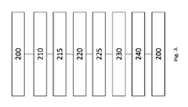
最も高い炭素含有量を有するStelliteおよび類似の既知のCo合金(約>2重量%(重量%))を図1に示す。 Stellite and similar known Co alloys (approximately >2 wt.% (wt.%)) with the highest carbon content are shown in FIG.
特許文献1は、最大3.5重量%の炭素含有量を有し、酸素含有量の低い合金を自由成形する方法を開示している。しかし、この特許は、高い炭素含有量とタングステン含有量の両方を有する合金または3D印刷物を開示していない。 US Pat. No. 5,300,000 discloses a method for free forming alloys with a carbon content of up to 3.5% by weight and a low oxygen content. However, this patent does not disclose alloys or 3D prints with both high carbon content and tungsten content.
本発明の目的は、先行技術の欠点を克服し、コバルト系合金に基づく3D印刷物、コバルト系合金、およびこれらの合金の1つまたはそれ以上を含む3D印刷物を製造する方法を提供することである。本発明は、新しい合金、新しい3D印刷方法、および大きなCr炭化物を回避でき、それにより高温での材料の硬度と靭性が向上するようなCr、WおよびC含有量を有するコバルト系合金を含む新しい3D印刷物を提供する。靭性は、クラックの開始という意味だけでなく、クラックの伝播に関しても増加する。さらに、本発明は、改善された耐疲労特性および耐熱衝撃性を提供する、小さく丸い均一に分布した炭化物を有する非常にきめ細かい微細構造を有する物を提供する。材料の機械的特性は、最大の炭化物の部位で破壊が発生する可能性が最も高いため、平均の炭化物サイズよりも最大の炭化物サイズに依存する。本出願は、積層造形に必要なこれらの合金の粉末造粒を促進する合金元素の独自の組み合わせを明らかにする。本発明は、焼結材料に見られる減少したサイズおよび多孔性という欠点、ならびに鋳造およびニアネットシェイプのPM-HIP物に見られる複雑さの制限という欠点を克服する。 SUMMARY OF THE INVENTION It is an object of the present invention to overcome the drawbacks of the prior art and to provide a method for producing 3D prints based on cobalt-based alloys, cobalt-based alloys, and 3D prints comprising one or more of these alloys. . The present invention provides new alloys, new 3D printing methods, and new cobalt-based alloys with Cr, W, and C contents such that large Cr carbides can be avoided, thereby improving the hardness and toughness of the material at high temperatures. Offer 3D prints. Toughness increases not only in terms of crack initiation, but also with respect to crack propagation. In addition, the present invention provides articles with a very fine microstructure with small, round, uniformly distributed carbides that provide improved fatigue and thermal shock resistance properties. The mechanical properties of a material depend more on the maximum carbide size than on the average carbide size, since fracture is most likely to occur at the site of the largest carbide. This application reveals a unique combination of alloying elements that facilitate powder granulation of these alloys required for additive manufacturing. The present invention overcomes the drawbacks of reduced size and porosity found in sintered materials and complexity limitations found in cast and near net shape PM-HIP articles.
本発明者は、融点が十分に低く、合金は入手が困難な異質元素を含まないため、ガス噴霧を用いて合金化前粉末の大規模生産を容易にする合金を使用する。さらに、3D印刷に通常使用されるよりも粗い粉末サイズ画分が使用される。 We use alloys that have sufficiently low melting points to facilitate large-scale production of prealloyed powders using gas atomization because the alloys do not contain foreign elements that are difficult to obtain. Additionally, coarser powder size fractions are used than typically used for 3D printing.
種々の炭化物生成の複合体バランス、マトリックス固体溶液(特にWの)、溶融および固化の範囲は、取り扱うのが非常に難しいが、本発明は、本発明の方法と組み合わせた元素の独自の組み合わせを採用することによりこれを解決する。 The complex balance of various carbide formations, matrix solid solutions (particularly of W), melting and solidifying extents are very difficult to handle, but the present invention provides a unique combination of elements combined with the method of the present invention. We solve this by adopting
第1の実施態様において、本発明は、金属マトリックスおよび該金属マトリックスに埋め込まれた炭化物の粒を含む合金で作られた3D印刷物であって、
合金が、
炭素:2.5重量%と等しいまたはそれを超え、かつ5重量%と等しいまたはそれ未満、
タングステン:12重量%と等しいまたはそれを超え、かつ30重量%と等しいまたはそれ未満、
クロム:12重量%と等しいまたはそれを超え、かつ27重量%と等しいまたはそれ未満、
コバルト:30重量%と等しいまたはそれを超える、
を含み;そして
合金が、1750℃未満、または好ましくは1600℃未満であり、しかし1300℃超の融点を有する
物に関する。
In a first embodiment, the present invention is a 3D print made of an alloy comprising a metal matrix and carbide grains embedded in the metal matrix, comprising:
the alloy
Carbon: greater than or equal to 2.5% by weight and less than or equal to 5% by weight;
Tungsten: greater than or equal to 12% by weight and less than or equal to 30% by weight;
Chromium: greater than or equal to 12% by weight and less than or equal to 27% by weight;
Cobalt: greater than or equal to 30% by weight,
and the alloy has a melting point below 1750°C, or preferably below 1600°C but above 1300°C.
第2の実施態様において、本発明は、金属マトリックスおよび該金属マトリックスに埋め込まれた炭化物の粒を含む合金で作られた3D印刷物であって、
合金が、
炭素:3.1重量%と等しいまたはそれを超え、かつ5.1重量%と等しいまたはそれ未満、
タングステン:18重量%と等しいまたはそれを超え、かつ30重量%と等しいまたはそれ未満、
クロム:15重量%と等しいまたはそれを超え、かつ24重量%と等しいまたはそれ未満、
コバルト:40重量%と等しいまたはそれを超える、
を含み;
クロムおよびタングステンの合計が36~48重量%であり;かつ
合金が、1750℃未満、または好ましくは1600℃未満であり、しかし1300℃超の融点を有する
物に関する。
In a second embodiment, the present invention is a 3D printed article made of an alloy comprising a metal matrix and carbide grains embedded in the metal matrix, comprising:
the alloy
carbon: greater than or equal to 3.1 wt% and less than or equal to 5.1 wt%;
Tungsten: greater than or equal to 18% by weight and less than or equal to 30% by weight;
Chromium: greater than or equal to 15% by weight and less than or equal to 24% by weight;
Cobalt: greater than or equal to 40% by weight,
includes;
The sum of chromium and tungsten is 36-48% by weight; and the alloy has a melting point below 1750°C, or preferably below 1600°C but above 1300°C.
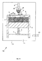
第3の実施態様において、本発明は、チャンバーを有する自由成形装置において本発明の3D印刷物を製造する方法であって、
a.チャンバー内の低酸素環境でコバルト系合金の粉末の層を形成する工程であり、前記合金が、
炭素:2.5重量%と等しいまたはそれを超え、かつ5重量%と等しいまたはそれ未満、
タングステン:12重量%と等しいまたはそれを超え、かつ30重量%と等しいまたはそれ未満、
クロム:12重量%と等しいまたはそれを超え、かつ27重量%と等しいまたはそれ未満、
コバルト:30重量%と等しいまたはそれを超える、
を含み;そして
合金が、1750℃未満、または好ましくは1600℃未満であり、しかし1300℃超の融点を有し;
前記粉末が実質的に球状の粒子および/またはサテライトを有する実質的に球状の粒子であり、かつ前記粒子が200μm以下の平均径を有する工程;
b.前記粉末層を300℃より高い温度に加熱する工程;
c.前記粉末を、溶融プールを形成するのに十分な時間エネルギービームに曝し、局所的に溶融する工程;および
d.溶融プール中の溶融した粉末を多相コバルト合金に固化する工程;
e.任意に、a~eの工程を繰り返し、工程bは先の層の上に粉末を置くことを含むことにより、先の層の上に粉末の付加的な層を製造する工程
を含み;かつ製作中の物は方法中400℃以上に加熱し続けられる
方法に関する。
In a third embodiment, the invention provides a method of manufacturing a 3D print of the invention in a free-form device having a chamber , comprising:
a. forming a layer of a cobalt-based alloy powder in a low-oxygen environment in a chamber, the alloy comprising:
Carbon: greater than or equal to 2.5% by weight and less than or equal to 5% by weight;
Tungsten: greater than or equal to 12% by weight and less than or equal to 30% by weight;
Chromium: greater than or equal to 12% by weight and less than or equal to 27% by weight;
Cobalt: greater than or equal to 30% by weight,
and the alloy has a melting point below 1750°C, or preferably below 1600°C but above 1300°C;
said powder is substantially spherical particles and/or substantially spherical particles with satellites, and said particles have an average diameter of 200 μm or less ;
b. heating the powder layer to a temperature above 300°C;
c. exposing the powder to an energy beam for a time sufficient to form a melt pool to locally melt; and
d. solidifying the molten powder in the melt pool into a multiphase cobalt alloy;
e. optionally repeating steps ae, step b comprising placing powder on the previous layer to produce an additional layer of powder on top of the previous layer.
and the article under construction relates to a method in which the object can be kept heated to 400° C. or higher during the method.
第4の実施態様において、本発明は、チャンバーを有する自由成形装置において本発明の3D印刷物を製造する方法であって、
a.チャンバー内の低酸素環境でコバルト系合金の粉末の層を形成する工程であり、前記合金が、
炭素:3.1重量%と等しいまたはそれを超え、かつ5.1重量%と等しいまたはそれ未満、
タングステン:18重量%と等しいまたはそれを超え、かつ30重量%と等しいまたはそれ未満、
クロム:15重量%と等しいまたはそれを超え、かつ24重量%と等しいまたはそれ未満、
コバルト:40重量%と等しいまたはそれを超える、
を含み;
クロムおよびタングステンの合計が36~48重量%であり;かつ
合金が、1750℃未満、または好ましくは1600℃未満であり、しかし1300℃超の融点を有し;
前記粉末が実質的に球状の粒子および/またはサテライトを有する実質的に球状の粒子であり、かつ前記粒子が200μm以下の平均径を有する工程;
b.前記粉末層を600℃より高い温度に加熱する工程;
c.前記粉末を、溶融プールを形成するのに十分な時間エネルギービームに曝し、局所的に溶融する工程;および
d.溶融プール中の溶融した粉末を多相コバルト合金に固化する工程;
e.任意に、a~eの工程を繰り返し、工程bは先の層の上に粉末を置くことを含むことにより、先の層の上に粉末の付加的な層を製造する工程
を含み;かつ製作中の物は方法中600℃以上に加熱し続けられる
方法に関する。
In a fourth embodiment, the invention provides a method of manufacturing a 3D print of the invention in a free-form device having a chamber , comprising:
a. forming a layer of a cobalt-based alloy powder in a low-oxygen environment in a chamber, the alloy comprising:
carbon: greater than or equal to 3.1 wt% and less than or equal to 5.1 wt%;
Tungsten: greater than or equal to 18% by weight and less than or equal to 30% by weight;
Chromium: greater than or equal to 15% by weight and less than or equal to 24% by weight;
Cobalt: greater than or equal to 40% by weight,
includes;
the sum of chromium and tungsten is 36-48% by weight; and the alloy has a melting point below 1750°C, or preferably below 1600°C, but above 1300°C;
said powder is substantially spherical particles and/or substantially spherical particles with satellites, and said particles have an average diameter of 200 μm or less ;
b. heating the powder layer to a temperature above 600°C;
c. exposing the powder to an energy beam for a time sufficient to form a melt pool to locally melt; and
d. solidifying the molten powder in the melt pool into a multiphase cobalt alloy;
e. optionally repeating steps ae, step b comprising placing powder on the previous layer to produce an additional layer of powder on top of the previous layer.
and the object under construction relates to a method in which the object can be kept heated to 600° C. or higher during the method.
第5の実施態様において、本発明は、金属マトリックスおよび該金属マトリックスに埋め込まれた炭化物の粒(または粒子(particles))を含むコバルト系合金粉末であって、
合金が、
炭素:2.5重量%と等しいまたはそれを超え、かつ5重量%と等しいまたはそれ未満、
タングステン:12重量%と等しいまたはそれを超え、かつ30重量%と等しいまたはそれ未満、
クロム:12重量%と等しいまたはそれを超え、かつ27重量%と等しいまたはそれ未満、
コバルト:30重量%以上
を含み;そして
合金が、1750℃未満、または好ましくは1600℃未満であり、しかし1300℃超の融点を有し;
該合金粉末が実質的に球状の粒子および/またはサテライトを有する実質的に球状の粒子であり、かつ該粒子が200μm以下の平均径を有する
合金粉末に関する。
In a fifth embodiment, the present invention is a cobalt-based alloy powder comprising a metal matrix and carbide grains (or particles) embedded in the metal matrix, comprising:
the alloy
Carbon: greater than or equal to 2.5% by weight and less than or equal to 5% by weight;
Tungsten: greater than or equal to 12% by weight and less than or equal to 30% by weight;
Chromium: greater than or equal to 12% by weight and less than or equal to 27% by weight;
Cobalt: 30% by weight or more; and the alloy has a melting point below 1750°C, or preferably below 1600°C, but above 1300°C;
The alloy powder is substantially spherical particles and/or substantially spherical particles having satellites, and the particles have an average diameter of 200 μm or less.
第6の実施態様において、本発明は、金属マトリックスおよび該金属マトリックスに埋め込まれた炭化物の粒(または粒子)を含むコバルト系合金粉末であって、
合金が、
炭素:3.1重量%と等しいまたはそれを超え、かつ5.1重量%と等しいまたはそれ未満、
タングステン:18重量%と等しいまたはそれを超え、かつ30重量%と等しいまたはそれ未満、
クロム:15重量%と等しいまたはそれを超え、かつ24重量%と等しいまたはそれ未満、
コバルト:40重量%と等しいまたはそれを超え、
を含み;
クロムおよびタングステンの合計が36~48重量%であり;
合金が、1750℃未満、または好ましくは1600℃未満であり、しかし1300℃超の融点を有し;
該合金粉末が実質的に球状の粒子および/またはサテライトを有する実質的に球状の粒子であり、かつ該粒子が200μm以下の平均径を有する
合金粉末に関する。
In a sixth embodiment, the present invention is a cobalt-based alloy powder comprising a metal matrix and carbide grains (or particles) embedded in the metal matrix,
the alloy
carbon: greater than or equal to 3.1 wt% and less than or equal to 5.1 wt%;
Tungsten: greater than or equal to 18% by weight and less than or equal to 30% by weight;
Chromium: greater than or equal to 15% by weight and less than or equal to 24% by weight;
Cobalt: equal to or greater than 40% by weight,
includes;
the sum of chromium and tungsten is 36-48% by weight;
the alloy has a melting point below 1750°C, or preferably below 1600°C but above 1300°C;
The alloy powder is substantially spherical particles and/or substantially spherical particles having satellites, and the particles have an average diameter of 200 μm or less.
本明細書に記載されるすべての実施形態は、特段の断りがない限り、本発明のすべての実施態様に適用できる。 All embodiments described herein are applicable to all implementations of the invention unless otherwise stated.
本出願において、三次元印刷または3D印刷または自由成形または積層造形という用語は同じことを意味し、互換的に使用される。 In this application, the terms three-dimensional printing or 3D printing or freeform or additive manufacturing mean the same thing and are used interchangeably.
本出願において、用語「融点」または「溶融温度」は同じものを意味し、互換的に使用され、液相線を示す。 In this application, the terms "melting point" or "melting temperature" mean the same thing and are used interchangeably to indicate the liquidus.
合金と3D印刷物
本発明の目的は、コバルト系合金で作られた、またはそれを含む三次元(3D)印刷物を提供することである。合金は、金属マトリックスと、その金属マトリックスに埋め込まれた炭化物の粒を含む。この合金はコバルトを基本に、さらにクロム、タングステンおよび炭素を含む。合金は、高炭素、高タングステンコバルト合金である。好ましくは、合金は非常に低い酸素含有量、好ましくは100重量ppmと等しいまたはそれ未満、より好ましくは50重量ppm未満の酸素含有量を有する。本発明の物の積層造形に使用される合金化粉末は、粉末の平均粒径が200μmと等しいまたはそれ未満である主に球状粒子の形態である。好ましくは、粉末の平均粒径は、20μmと等しいまたはそれを超え、かつ200μmと等しいまたはそれ未満である。より好ましくは、粉末の平均粒径は、40μmと等しいまたはそれを超え、かつ150μmと等しいまたはそれ未満である。本発明による合金粉末は、ガス噴霧により製造することができる。
Alloys and 3D Prints It is an object of the present invention to provide three-dimensional (3D) prints made of or containing cobalt-based alloys. The alloy comprises a metal matrix and carbide grains embedded in the metal matrix. This alloy is based on cobalt and additionally contains chromium, tungsten and carbon. The alloy is a high carbon, high tungsten cobalt alloy. Preferably, the alloy has a very low oxygen content, preferably less than or equal to 100 ppm by weight, more preferably less than 50 ppm by weight. The alloying powders used for additive manufacturing of the articles of the invention are in the form of predominantly spherical particles with an average particle size of the powders equal to or less than 200 μm. Preferably, the average particle size of the powder is equal to or greater than 20 μm and equal to or less than 200 μm. More preferably, the average particle size of the powder is equal to or greater than 40 μm and equal to or less than 150 μm. The alloy powder according to the invention can be produced by gas atomization.
合金中のコバルト含有量は30重量%と等しいまたはそれを超える。一実施形態では、含有量は、35重量%と等しいまたはそれを超え、40重量%と等しいまたはそれを超え、または45重量%と等しいまたはそれを超え、または50重量%と等しいまたはそれを超え、好ましくは73.5重量%と等しいまたはそれ未満、または70重量%と等しいまたはそれ未満、または65重量%と等しいまたはそれ未満、または55重量%と等しいまたはそれ未満である。一実施形態では、コバルト含有量は45~55重量%である。一実施形態では、コバルト含有量は残余(balanced)として定義される。 The cobalt content in the alloy is equal to or greater than 30% by weight. In one embodiment, the content is equal to or greater than 35 wt%, equal to or greater than 40 wt%, or equal to or greater than 45 wt%, or equal to or greater than 50 wt%. , preferably equal to or less than 73.5 wt%, or equal to or less than 70 wt%, or equal to or less than 65 wt%, or equal to or less than 55 wt%. In one embodiment, the cobalt content is 45-55% by weight. In one embodiment, cobalt content is defined as balanced.
本発明の合金中のクロム含有量は、12重量%と等しいまたはそれを超え、かつ25重量%と等しいまたはそれ未満である。一実施形態において、クロム含有量は、14重量%と等しいまたはそれを超え、または16重量%と等しいまたはそれを超え、好ましくは24重量%と等しいまたはそれ未満、または22重量%と等しいまたはそれ未満、または20重量%と等しいまたはそれ未満である。または18重量%と等しいまたはそれ未満である。一実施形態では、クロム含有量は、12重量%と等しいまたはそれを超え、かつ22重量%と等しいまたはそれ未満である。別の実施形態では、クロム含有量は12重量%と等しいまたはそれを超え、かつ15重量%と等しいまたはそれ未満である。別の実施形態では、クロム含有量は14重量%と等しいまたはそれを超え、かつ18重量%と等しいまたはそれ未満である。さらに別の実施形態では、クロム含有量は19重量%と等しいまたはそれを超え、かつ22重量%と等しいまたはそれ未満である。 The chromium content in the alloys of the invention is equal to or greater than 12 wt% and equal to or less than 25 wt%. In one embodiment, the chromium content is equal to or greater than 14 wt%, or equal to or greater than 16 wt%, preferably equal to or less than 24 wt%, or equal to or greater than 22 wt%. less than, or equal to or less than 20% by weight. or less than or equal to 18% by weight. In one embodiment, the chromium content is equal to or greater than 12 wt% and equal to or less than 22 wt%. In another embodiment, the chromium content is equal to or greater than 12 wt% and equal to or less than 15 wt%. In another embodiment, the chromium content is equal to or greater than 14 wt% and equal to or less than 18 wt%. In yet another embodiment, the chromium content is equal to or greater than 19 wt% and equal to or less than 22 wt%.
タングステンは、12重量%と等しいまたはそれを超え、かつ30重量%と等しいまたはそれ未満の含有量で合金に存在する。一実施形態において、タングステン含有量は、15重量%と等しいまたはそれを超え、または20重量%と等しいまたはそれを超え、または22重量%と等しいまたはそれを超え、または24重量%と等しいまたはそれを超え、好ましくは29重量%と等しいまたはそれ未満、または27重量%と等しいまたはそれ未満、または25重量%と等しいまたはそれ未満である。別の実施形態では、タングステン含有量は、20重量%と等しいまたはそれを超え、かつ30重量%と等しいまたはそれ未満、または21重量%と等しいまたはそれを超え、かつ29重量%と等しいまたはそれ未満である。 Tungsten is present in the alloy in a content equal to or greater than 12 wt.% and equal to or less than 30 wt.%. In one embodiment, the tungsten content is equal to or greater than 15 wt%, or equal to or greater than 20 wt%, or equal to or greater than 22 wt%, or equal to or greater than 24 wt%. and preferably equal to or less than 29 wt%, or equal to or less than 27 wt%, or equal to or less than 25 wt%. In another embodiment, the tungsten content is equal to or greater than 20 wt% and equal to or less than 30 wt%, or equal to or greater than 21 wt% and equal to or less than 29 wt%. is less than
クロムおよびタングステンの量は融点に影響するため、2つの合計は50重量%未満であることが好ましい。一実施形態では、クロムおよびタングステン含有量の合計は、48重量%と等しいまたはそれ未満、または46重量%と等しいまたはそれ未満、または44重量%と等しいまたはそれ未満である。一実施形態では、タングステンの重量%の量は、クロムの重量%の量と等しいまたはそれを超える。 The amount of chromium and tungsten affects the melting point, so the sum of the two is preferably less than 50% by weight. In one embodiment, the total chromium and tungsten content is equal to or less than 48 wt%, or equal to or less than 46 wt%, or equal to or less than 44 wt%. In one embodiment, the weight percent amount of tungsten equals or exceeds the weight percent amount of chromium.
カーボンは、合金に存在するタングステンとタングステン炭化物を形成し、これらの炭化物は、3D印刷物に機械的強度と硬度を提供する。本発明の合金の炭素含有量は、2.5重量%と等しいまたはそれを超え、かつ5重量%と等しいまたはそれ未満である。本発明の一実施形態では、炭素含有量は、2.7重量%と等しいまたはそれを超え、または2.9重量%と等しいまたはそれを超え、または3.1重量%と等しいまたはそれを超え、または3.3重量%と等しいまたはそれを超え、3.5重量%と等しいまたはそれを超え、または3.7重量%と等しいまたはそれを超え、または3.9重量%と等しいまたはそれを超え、好ましくは4.8重量%と等しいまたはそれ未満、または4.6重量%と等しいまたはそれ未満、または4.4重量%と等しいまたはそれ未満、または4.2重量%と等しいまたはそれ未満、または4.0重量%と等しいまたはそれ未満である。別の実施形態では、炭素含有量は、2.7重量%と等しいまたはそれを超え、かつ4.5重量%と等しいまたはそれ未満、例えば2.9重量%と等しいまたはそれを超え、かつ4.2重量%と等しいまたはそれ未満、または3.1重量%~3.9重量%である。 Carbon forms tungsten carbides with tungsten present in the alloy, and these carbides provide mechanical strength and hardness to 3D prints. The carbon content of the alloy of the present invention is equal to or greater than 2.5 wt% and equal to or less than 5 wt%. In one embodiment of the invention, the carbon content is equal to or greater than 2.7 wt%, or equal to or greater than 2.9 wt%, or equal to or greater than 3.1 wt%. , or equal to or greater than 3.3 wt%, or equal to or greater than 3.5 wt%, or equal to or greater than 3.7 wt%, or equal to or greater than 3.9 wt% greater than, preferably equal to or less than 4.8 wt%, or equal to or less than 4.6 wt%, or equal to or less than 4.4 wt%, or equal to or less than 4.2 wt% , or less than or equal to 4.0% by weight. In another embodiment, the carbon content is equal to or greater than 2.7 wt% and equal to or less than 4.5 wt%, such as equal to or greater than 2.9 wt% and 4 less than or equal to .2 wt%, or between 3.1 wt% and 3.9 wt%.
本発明の一実施形態では、合金は、15重量%と等しいまたはそれを超え、かつ20重量%と等しいまたはそれ未満のクロム含有量、13重量%と等しいまたはそれを超え、かつ30重量%と等しいまたはそれ未満のタングステン含有量、および2.7重量%と等しいまたはそれを超え、かつ4.2重量%と等しいまたはそれ未満の炭素含有量を有する。 In one embodiment of the invention, the alloy has a chromium content equal to or greater than 15 wt% and equal to or less than 20 wt%, a chromium content equal to or greater than 13 wt% and 30 wt% It has a tungsten content equal to or less than 2.7 weight percent and a carbon content equal to or greater than 2.7 weight percent and equal to or less than 4.2 weight percent.
別の実施形態では、合金は、12重量%と等しいまたはそれを超え、かつ15重量%と等しいまたはそれ未満のクロム含有量、27重量%と等しいまたはそれを超え、かつ30重量%と等しいまたはそれ未満のタングステン含有量、および2.7重量%と等しいまたはそれを超え、かつ3.0重量%と等しいまたはそれ未満の炭素含有量を有する。 In another embodiment, the alloy has a chromium content equal to or greater than 12 wt% and equal to or less than 15 wt%, equal to or greater than 27 wt% and equal to 30 wt% or It has a tungsten content less than that and a carbon content equal to or greater than 2.7 wt% and equal to or less than 3.0 wt%.
さらに別の実施形態では、合金は、19重量%と等しいまたはそれを超え、かつ22重量%と等しいまたはそれ未満のクロム含有量、20重量%と等しいまたはそれを超え、かつ22重量%と等しいまたはそれ未満のタングステン含有量、および3.7重量%と等しいまたはそれを超え、かつ4.2重量%と等しいまたはそれ未満の炭素含有量を有する。 In yet another embodiment, the alloy has a chromium content equal to or greater than 19 wt% and equal to or less than 22 wt%, greater than or equal to 20 wt% and equal to 22 wt% Tungsten content of or less than or equal to and carbon content equal to or greater than 3.7 wt% and equal to or less than 4.2 wt%.
さらに別の実施形態において、合金は、18重量%と等しいまたはそれを超え、かつ20重量%と等しいまたはそれ未満のクロム含有量、21重量%と等しいまたはそれを超え、かつ25重量%と等しいまたはそれ未満のタングステン含有量、および3.9重量%と等しいまたはそれを超え、かつ4.3重量%と等しいまたはそれ未満の炭素含有量を有し、残余がコバルトである。 In yet another embodiment, the alloy has a chromium content equal to or greater than 18 wt% and equal to or less than 20 wt%, greater than or equal to 21 wt% and equal to 25 wt% or less, and a carbon content equal to or greater than 3.9 wt.% and equal to or less than 4.3 wt.%, the balance being cobalt.
さらに別の実施形態では、合金は、19重量%と等しいまたはそれを超え、かつ21重量%と等しいまたはそれ未満のクロム含有量、20重量%と等しいまたはそれを超え、かつ23重量%と等しいまたはそれ未満のタングステン含有量、および3.8重量%と等しいまたはそれを超え、かつ4.2重量%と等しいまたはそれ未満の炭素含有量、ならびに残部としてのコバルトを有し、クロムとタングステンの含有量の合計(Cr+W)が41~42%など40~43%であり、クロム/炭素比は、5.0~5.3など、4.5~5.5である。 In yet another embodiment, the alloy has a chromium content equal to or greater than 19 wt% and equal to or less than 21 wt%, greater than or equal to 20 wt% and equal to 23 wt% or less tungsten content, and a carbon content equal to or greater than 3.8 wt.% and equal to or less than 4.2 wt.%, and cobalt as the balance; The total content (Cr+W) is 40-43%, such as 41-42%, and the chromium/carbon ratio is 4.5-5.5, such as 5.0-5.3.
さらに別の実施形態では、合金は、25重量%と等しいまたはそれを超え、かつ27重量%と等しいまたはそれ未満のクロム含有量、15重量%と等しいまたはそれを超え、かつ17重量%と等しいまたはそれ未満のタングステン含有量、および4.4重量%と等しいまたはそれを超え、かつ4.6重量%と等しいまたはそれ未満の炭素含有量を有する。 In yet another embodiment, the alloy has a chromium content equal to or greater than 25 wt% and equal to or less than 27 wt%, equal to or greater than 15 wt% and equal to 17 wt% It has a tungsten content of or less than or equal to and a carbon content equal to or greater than 4.4 wt% and equal to or less than 4.6 wt%.
合金は、他の元素の痕跡量または不純物をさらに含んでもよい。これらの元素は、ニオブ、ニッケル、マンガン、ケイ素、モリブデン、ホウ素、タンタル、および鉄、またはそれらの組み合わせであってもよいが、これらに限定されるものではない。一実施形態では、合金は、ニオブ、ニッケル、マンガン、ケイ素および鉄のうちの少なくとも1つを含む。一実施形態では、合金は、ニオブ、ニッケル、マンガン、ケイ素および鉄のうちの少なくとも1つを3重量%まで含む。一実施形態では、合金は、ニオブ、ニッケル、マンガン、ケイ素、および鉄のうちの少なくとも1つを、0.5重量%と等しいまたはそれを超え、または1重量%と等しいまたはそれを超え、または2重量と等しいまたはそれを超え、ただし3重量%と等しいまたはそれ未満含む。ニオブ、ニッケル、マンガン、ケイ素および鉄などの他の元素の合計含有量は1~5重量%とすることができる。 The alloy may further contain traces or impurities of other elements. These elements may be, but are not limited to, niobium, nickel, manganese, silicon , molybdenum, boron, tantalum, and iron, or combinations thereof. In one embodiment, the alloy includes at least one of niobium, nickel, manganese, silicon and iron. In one embodiment, the alloy comprises up to 3% by weight of at least one of niobium, nickel, manganese, silicon and iron. In one embodiment, the alloy comprises at least one of niobium, nickel, manganese, silicon, and iron equal to or greater than 0.5 wt%, or equal to or greater than 1 wt%, or Equal to or greater than 2% by weight, but equal to or less than 3% by weight. The total content of other elements such as niobium, nickel, manganese, silicon and iron can be 1-5% by weight.
合金の構成要素および構成要素の量は、溶融温度が1750℃と等しいまたはそれ未満、好ましくは1600℃と等しいまたはそれ未満、または1500℃と等しいまたはそれ未満となるように選択される。合金および物の特性を最適化するために、合金の溶融温度は、1300℃と等しいまたはそれを超え、または1350℃と等しいまたはそれを超え、または1400℃と等しいまたはそれを超えることが好ましい。1600℃未満の溶融温度を有する合金を使用することの1つの利点は、球状粉末画分を生成する周知の粉末冶金技術の多くを、本発明の合金粉末の製造に使用できることである。 The components and component amounts of the alloy are selected such that the melting temperature is equal to or less than 1750°C, preferably equal to or less than 1600°C, or equal to or less than 1500°C. The melting temperature of the alloy is preferably equal to or greater than 1300°C, or equal to or greater than 1350°C, or equal to or greater than 1400°C, in order to optimize the properties of the alloy and article. One advantage of using alloys with melting temperatures below 1600° C. is that many of the well-known powder metallurgy techniques that produce spherical powder fractions can be used to produce the alloy powders of the present invention.
本発明の1つの利点は、有機結合剤または接着剤の使用を必要としないことであり、それにより、3D印刷物は通常、95重量%と等しいまたはそれを超え、の炭素、タングステン、クロムおよびコバルトの合計含有量を含む。本発明の一実施形態では、炭素、タングステン、クロムおよびコバルトの合計含有量は、97重量%と等しいまたはそれを超える。好ましくは、炭素、タングステン、クロムおよびコバルトの合計含有量は98重量%と等しいまたはそれを超える。より好ましくは、炭素、タングステン、クロムおよびコバルトの合計含有量は99重量%と等しいまたはそれを超える。最も好ましくは、炭素、タングステン、クロム、およびコバルトの合計含有量は99.9重量%と等しいまたはそれを超え、である。本発明の一実施形態では、3D印刷物中の有機化合物の量は、0.1重量%と等しいまたはそれ未満である。好ましくは、3D印刷物中の有機化合物の量は0.05重量%と等しいまたはそれ未満である。本発明の一実施形態では、製品は本質的に有機化合物を含まない。製品中の炭素は、主にタングステンやクロムの炭化物などの炭化物の形態であるが、元素の炭素と元素のタングステンもマトリックスに存在することができる。 One advantage of the present invention is that it does not require the use of organic binders or adhesives, so that 3D prints typically equal or exceed 95% by weight of carbon, tungsten, chromium and cobalt. including the total content of In one embodiment of the invention, the total content of carbon, tungsten, chromium and cobalt is equal to or greater than 97% by weight. Preferably, the total carbon, tungsten, chromium and cobalt content is equal to or greater than 98% by weight. More preferably, the total content of carbon, tungsten, chromium and cobalt is equal to or greater than 99% by weight. Most preferably, the total content of carbon, tungsten, chromium and cobalt is equal to or greater than 99.9% by weight. In one embodiment of the invention, the amount of organic compound in the 3D print is less than or equal to 0.1 wt%. Preferably, the amount of organic compounds in the 3D print is less than or equal to 0.05 wt%. In one embodiment of the invention, the product is essentially free of organic compounds. The carbon in the product is primarily in the form of carbides such as carbides of tungsten and chromium, although elemental carbon and elemental tungsten can also be present in the matrix.
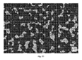
炭化物を含む金属化合物は、炭化物がクラスター、樹枝状または網目構造を形成し、材料をより脆くすることがある。通常、これらの種類の合金、特に高Cr(~30重量%)およびC(~2.5重量%)含量またはそれ以上の合金では、Crが炭化物(Cr7C3やCr23C6、その他の化学量論的タイプなど)を形成する。これらの炭化物は通常、固化段階で急速に成長し、その結果、サイズが100~1000μmの大きく長いストリンガー(stringer)が生成される(図6~11参照)。これらの大きくて鋭い形状の炭化物は、応力集中をもたらし、材料のマクロ破壊靭性、熱衝撃、および疲労耐性を低下させる。したがって、本発明の利点の1つは、3D製品が、従来技術で見られるものよりも一般に小さく、マトリックス中に十分に分散している炭化物の粒(grains)または粒子(particles)を含むことである。これは、一方でCr含有量を減らし、他方で積層造形技術を使用して非常に急速な固化速度を確保することにより達成さる。 Metal compounds containing carbides may form clusters, dendrites or networks of carbides, making the material more brittle. Typically, in these types of alloys, especially alloys with high Cr (~ 30 wt%) and C (~2.5 wt%) contents or higher, Cr forms carbides ( Cr7C3 , Cr23C6 , etc.). such as the stoichiometric type of ). These carbides usually grow rapidly during the solidification stage, resulting in the formation of large long stringers 100-1000 μm in size (see FIGS. 6-11). These large, sharp-shaped carbides create stress concentrations and reduce the macro-fracture toughness, thermal shock, and fatigue resistance of the material. Thus, one of the advantages of the present invention is that the 3D products contain grains or particles of carbide that are generally smaller and well dispersed in the matrix than those found in the prior art. be. This is achieved by reducing the Cr content on the one hand and using additive manufacturing techniques on the other hand to ensure a very rapid solidification speed.
多相合金は、主にコバルトのみならず、クロム、タングステンおよび炭素のマトリックスを含む。マトリックスには、クロムとタングステンの炭化物、CrCタイプおよびWCが存在する。炭化クロムは、炭化タングステンを取り囲んでいてよく、同様に炭化タングステンはマトリックスによって取り囲まれている。 Multiphase alloys contain matrices of chromium, tungsten and carbon, as well as predominantly cobalt. In the matrix are chromium and tungsten carbides, CrC type and WC. Chromium carbide may surround tungsten carbide, which in turn is surrounded by a matrix.
本発明の1つの利点は、3D印刷物の改善された機械的特性の達成である。HIP後の物の硬度は、少なくとも750HV、または少なくとも800HV、または少なくとも850HV、または少なくとも870HVなど、少なくとも700HVであり得る。一実施形態では、硬度は800~950HVまたは850~900HVである。HIPプロセスは、物を、1000バール(100MPa)、1120~1160℃で3時間保つことにより行われた。一実施形態では、HIP前の硬度は970~1000HV2kgである。硬度は、標準SS-EN ISO 6507に従って、2kgのビッカース圧痕を用いて決定された。さらに、総クラック長、すなわち室温で250kgのビッカースインデントを用いてダイヤモンド形のくぼみの角に形成された最大4個のクラックの合計として測定された破壊靭性は非常に高く、クラック長は350μmと等しいかまたはそれ未満、または300μmまたはそれ未満、または250μmまたはそれ未満、または150μm以下、または100μmまたはそれ未満、または50μmまたはそれ未満、または30μmまたはそれ未満、または10μmまたはそれ未満の短さであり得る。一実施形態では、クラックは形成されなかった。クラック長は、Palmqvist破壊靭性法を使用して決定されたが、より高い荷重(250kg)で、本明細書中、クラック長の合計としてのみ表示され、Klc値として表示されるものではない。圧痕は、サンプルの3つの異なる場所で3回実行され、クラック長の合計の平均が表示される。より高い荷重を使用する理由は、より低い荷重ではクラックが形成されないことが多く、したがって靭性の値が得られないためである。クラック長の圧痕試験は、硬度標準ASTM E384-16と同じ方法で、断面サンプルで行われ、1μmのダイヤモンド懸濁液まで段階的に研磨された(groundおよびpolished)。本発明による合金または物の多くは、試験中にクラックを全く形成しない。しかしながら、750℃または800℃などの高温での破壊靭性の測定は非常に困難であるが、最大の「誤差」または「不完全性」によって設定される最大応力点で材料にクラックの発生が起こることはよく知られている。本発明に記載されるような合金において、この最大の「誤差」または「不完全性」が最も大きな炭化物である。 One advantage of the present invention is the achievement of improved mechanical properties of 3D prints. The hardness of the article after HIP can be at least 700HV, such as at least 750HV, or at least 800HV, or at least 850HV, or at least 870HV. In one embodiment, the hardness is 800-950 HV or 850-900 HV. The HIP process was performed by holding the article at 1000 bar (100 MPa) and 1120-1160° C. for 3 hours. In one embodiment, the hardness before HIP is 970-1000 HV2 kg. Hardness was determined according to standard SS-EN ISO 6507 using a 2 kg Vickers indentation. Furthermore, the total crack length, i.e. the fracture toughness measured as the sum of up to four cracks formed at the corners of a diamond-shaped indentation with a Vickers indentation of 250 kg at room temperature, is very high, with a crack length equal to 350 μm. or 300 μm or less, or 250 μm or less, or 150 μm or less, or 100 μm or less, or 50 μm or less, or 30 μm or less, or 10 μm or less . In one embodiment, no cracks were formed. Crack length was determined using the Palmqvist fracture toughness method, but at higher loads (250 kg) and is expressed herein only as the total crack length and not as the Klc value. The indentation was performed in triplicate at three different locations on the sample and the average total crack length is displayed. The reason for using higher loads is that lower loads often do not form cracks and therefore do not yield toughness values. Crack length indentation testing was performed on cross-sectional samples in the same manner as hardness standard ASTM E384-16, ground and polished stepwise to a 1 μm diamond suspension. Many of the alloys or articles according to the invention do not form any cracks during testing. However, measuring fracture toughness at high temperatures, such as 750°C or 800°C, is very difficult, and cracking occurs in the material at the point of maximum stress set by the maximum 'error' or 'imperfection'. It is well known. In alloys such as those described in this invention, this largest "error" or "imperfection" is the largest carbide.
理論に拘束されるものではないが、本発明の機械的特性は、物のきめ細かい微細構造の結果であると考えられている。3D印刷物には、本質的に炭化物の粒の樹枝状構造がなく、代わりに炭化物は本質的に球形または円形である。炭化物の粒はサイズが小さく、図に見られるようにマトリックス内に均等に分布している。3D印刷物の合金は、通常、30μmと等しいまたはそれを超えるサイズを有する炭化物を含まず、そのサイズは好ましくは20μm以下、または10μm以下である。一実施形態では、最大炭化物サイズは5μmである。なお、印刷物の炭化物の総量は非常に多く、面積の少なくとも50容量%、または少なくとも60容量%、または少なくとも65容量%である。一実施形態では、炭化物の総量は、68容量%など、65~70容量%である。サンプル中の炭化物の総量は、SEMを使用して決定される。サンプル表面が選択され、物の代表であると考えられる。各炭化物の縁にマークが付けられ、そこから総炭化物面積を適切なソフトウェアを用いて計算する。図25~27は、炭化物の縁がマークされている例を示す。次に、炭化物の体積分率が計算された面積から換算される。炭化物の平均面積は、5μm2またはそれ未満、例えば3μm2以下それ未満であってもよい。これらの図では、炭化物の面積とサイズは、見ることが難しいため計算されていない。 Without being bound by theory, it is believed that the mechanical properties of the present invention are a result of the fine-grained microstructure of the object. The 3D prints are essentially devoid of char grain dendrites, instead the chars are essentially spherical or circular. The carbide grains are small in size and evenly distributed within the matrix as seen in the figure. The alloy of the 3D print is typically free of carbides with a size equal to or greater than 30 μm, preferably 20 μm or less , or 10 μm or less. In one embodiment, the maximum carbide size is 5 microns. It should be noted that the total amount of char in the print is very high, at least 50% by volume, or at least 60% by volume, or at least 65% by volume. In one embodiment, the total amount of carbide is 65-70% by volume, such as 68% by volume. The total amount of carbides in the sample is determined using SEM. A sample surface is selected and considered representative of the object. The edge of each carbide is marked, from which the total carbide area is calculated using appropriate software. Figures 25-27 show examples where the carbide edges are marked. The carbide volume fraction is then converted from the calculated area. The average area of the carbides may be 5 μm 2 or less, such as 3 μm 2 or less. In these figures the area and size of the carbides are not calculated because they are difficult to see.
本発明は、腐食に耐え得る改善された機械的特性を有する物およびコンポーネントの製造を容易にするだけでなく、高度または複雑な三次元形状および形態を有する物を製造することをも可能にする。物は、空洞、チャネルまたは穴を含んでもよく、物は湾曲部分または螺旋形を有してもよい。これらの形状または形態は、任意の後処理に加えて、合金を除去せずに製造される。空洞、穴またはチャネルは湾曲していてもよく、すなわち、それらの表面は湾曲していても、らせん状(helical)または螺旋状(spiral)などであってもよい。いくつかの実施形態では、物は空洞を含み、その空洞は密閉されているか、開口部を有し、その開口部の直径または幅は、下にある空洞の直径または幅よりも小さい。物は、フライスカッター、シェーパーカッター、パワースカイビングカッター、ドリル、フライス工具などの切削工具、または押出ヘッド、伸線ダイス、熱間圧延ロールなどの成形工具、またはポンプもしくはバルブコンポーネント、滑空もしくはロールベアリングリングなどの摩耗部品などであってもよい。 The present invention not only facilitates the production of objects and components with improved mechanical properties that can withstand corrosion, but also allows the production of objects with advanced or complex three-dimensional shapes and forms. . The object may contain cavities, channels or holes, and the object may have curved portions or helices. These shapes or forms are produced without alloy removal in addition to any post-treatment. The cavities, holes or channels may be curved, ie their surfaces may be curved, helical or spiral, or the like. In some embodiments, the article includes a cavity that is closed or has an opening, the diameter or width of the opening being smaller than the diameter or width of the underlying cavity. Articles may be cutting tools such as milling cutters, shaper cutters, power skiving cutters, drills, milling tools, or forming tools such as extrusion heads, wire drawing dies, hot rolling rolls, or pump or valve components, glide or roll bearings It may be a wear part such as a ring.
方法
本発明の物は、合金粉末の三次元印刷(自由成形、積層造形としても知られる)によって製造される。この方法は、粉末が配置されるチャンバーを有する自由成形装置(3Dプリンタまたは積層造形機)を使用する。自由成形の方法は、以下に定義されるように、チャンバー内の低酸素環境で合金の粉末の層を形成することを含む。1つの好適な自由成形装置は、ARCAM A2XなどのArcamの電子ビーム装置(EBM)である。合金は、炭素、タングステン、クロムおよびコバルトを上述の量で含み、合金の選択は最終物の所望の特性に依存する。反応器内の酸素および他の不純物の含有量は、10ppmと等しいまたはそれ未満(ガス純度グレード5に相当)、または1ppmと等しいまたはそれ未満(ガス純度グレード6に相当)など、可能な限り低くすべきであり、反応器内の環境は、アルゴンまたはヘリウムなどの不活性ガスを含むことができる。また、反応器内は、反応器内の圧力を1×10⁴mBar(0.01Pa)またはそれ未満、または1×10³mBar(0.1Pa)またはそれ未満とし得る真空であってもよい。一実施形態では、反応器内の初期圧力は約1~10×105mBar(1~10×103Pa)であり、次いでヘリウムまたはアルゴンなどの不活性ガスを加えて、圧力を1~5×10³mBar(0.1~0.5Pa)まで増加させる。次に、粉末を溶融するのに十分な時間、粉末をエネルギービームにさらすことにより、粉末を局所的に溶融する。エネルギービームは、レーザービームでも電子ビームでもよい。ビームは、パターン内でパウダー全体をスイープする。スイープの持続時間は、合金および粉末中の粒子のサイズに応じて、数秒から数分まで変化し得る。次いで、溶融粉末は、少なくとも部分的に固化して多相コバルト合金になる。次に、固化した合金の上に別の粉末層を適用することができる。
Methods The articles of the present invention are manufactured by three-dimensional printing (free-forming, also known as additive manufacturing) of alloy powders. This method uses a free-form device (3D printer or additive manufacturing machine) that has a chamber in which the powder is placed. The method of free forming involves forming a layer of alloy powder in a low-oxygen environment within a chamber, as defined below. One suitable freeform machine is an Arcam electron beam machine (EBM) such as the ARCAM A2X. The alloy contains carbon, tungsten, chromium and cobalt in the amounts mentioned above, with the choice of alloy depending on the desired properties of the final product. The content of oxygen and other impurities in the reactor is as low as possible, such as equal to or less than 10 ppm (equivalent to gas purity grade 5) or equal to or less than 1 ppm (equivalent to gas purity grade 6) should be, and the environment within the reactor may contain an inert gas such as argon or helium. There may also be a vacuum within the reactor which allows the pressure within the reactor to be 1×10 4 mBar (0.01 Pa) or less, or 1×10 3 mBar (0.1 Pa) or less. In one embodiment, the initial pressure in the reactor is about 1-10×10 5 mBar (1-10×10 3 Pa) and then an inert gas such as helium or argon is added to reduce the pressure from 1-5. Increase to ×10 3 mBar (0.1-0.5 Pa). The powder is then locally melted by exposing the powder to the energy beam for a time sufficient to melt the powder. The energy beam may be a laser beam or an electron beam. The beam sweeps across the powder in the pattern. The duration of the sweep can vary from seconds to minutes depending on the size of the particles in the alloy and powder. The molten powder is then at least partially solidified into a multiphase cobalt alloy. Another powder layer can then be applied over the solidified alloy.
クラックの形成を回避するために、物は、3D印刷物の印刷中または形成中に高温に維持される。クラックの形成は、おそらく、低温での内部応力の増加と材料の脆性の増加との組み合わせによるものである。内部応力の増加は、相変態時の体積変化によって引き起こされる。そのような変態の1つは、例えば430℃付近で起こり、そこでは面心立方格子構造が六方最密充填構造に変換されるが、高温では他の相変態も生じる。例えば、物が構築されるプレートまたはテーブルはヒーターを備えていてもよい。それにより、3D印刷物には、物の構築中に温度勾配が生じ得るが、物の最低温度、または構築プロセス中に物が構築されるプレートまたはテーブルの温度は、300℃またはそれより高い、または400℃またはそれより高い、または500℃またはそれより高い、または550℃またはそれより高い、または600℃またはそれより高い、または700℃またはそれより高い、または800℃またはそれより高い、または900℃またはそれより高いことが好ましいが、合金の溶融温度より低い、通常は1100℃以下、または1000℃またはそれ未満が好ましい。 To avoid the formation of cracks, the object is kept at a high temperature during the printing or forming of the 3D print. Crack formation is probably due to a combination of increased internal stress at low temperatures and increased brittleness of the material. The increase in internal stress is caused by volume change during phase transformation. One such transformation occurs, for example, around 430° C., where the face-centered cubic lattice structure transforms into a hexagonal close-packed structure, but other phase transformations also occur at higher temperatures. For example, the plate or table on which the object is built may be equipped with a heater. Thereby, the 3D printed object may have a temperature gradient during the building of the object, but the minimum temperature of the object, or the temperature of the plate or table on which the object is built during the building process, is 300° C. or higher, or 400°C or higher, or 500°C or higher, or 550°C or higher, or 600°C or higher, or 700°C or higher, or 800°C or higher, or 900°C or higher is preferred, but below the melting temperature of the alloy, typically 1100°C or less, or 1000°C or less is preferred.
図3は、1つの層を製造するための本発明の方法の一実施形態の工程のフロー図を示す。金属多相材料の製造方法は、工程200で開始される。工程210では、初期金属多相材料の粉末材料が提供される。次に、構築プラットフォームが、走査ビームまたは別の外部加熱方法の工程215によって加熱される。初期の金属多相材料は、炭化物が埋め込まれた金属マトリックスを含む。加工開始前に、環境から酸素が除去され、ビルドサポートが予熱される215。初期金属多相材料の粉末が、工程220で、先に定義された低酸素環境に置かれる。初期金属多相材料の粉末は、温度を維持するために最初に2つの工程225で予熱され、次に工程230で第1の部分で局所的に溶融されることが好ましい。工程240では、最終的な金属多相材料が固化される。この方法は工程299で終了する。
FIG. 3 shows a flow diagram of the steps of one embodiment of the method of the invention for manufacturing one layer. The method of manufacturing a metallic multiphase material begins at
図4は、本発明の3D物を生産する方法の別の実施形態の工程のフロー図を示す。金属多相材料の物体の製造方法は、工程200で開始する。好ましくは、金属粉末床の連続予熱が、2つの工程、PreHeat1およびPreHeat2で行われ、PreHeat1は、エネルギービームで、構築プレート領域全体で行われ(例えば、42mAのビームエネルギーで10回繰り返される)、PreHeat2は、意図する次の溶融帯領域付近で行われる(例えば、ビームエネルギー47mAで、6回繰り返される)。予熱工程の目的は、構築の高温を維持し、新たに追加された粉末を下層に焼結することである。この方法は、図3の金属多相材料の製造方法のすべての工程210、215、220、225、230および240を含む。工程220は、この実施形態では、上述したように初期の金属多相材料の薄層が低酸素環境で提供される工程221を含む。好ましくは、プロセスは、完全な目的が達成されるまで、破線矢印260で示されるように工程220から繰り返され、そして方法は工程299で終了する。
FIG. 4 shows a flow diagram of the steps of another embodiment of the method of producing a 3D object of the present invention. A method of manufacturing an object of metallic multiphase material begins at
レーザーと比較してEBMを使用する利点は、より厚い粉体層を製造することができ、より大きな粒子の粉体を使用できることである。 The advantage of using EBM compared to lasers is that thicker powder layers can be produced and larger particle powders can be used.
炭化物の成長は、溶融材料の固化中に生じ、炭化物のサイズを制限するためには、成長時間を制限すべきである。固化時間は、主に熱拡散率、固化熱、および熱拡散距離に影響される。従来の鋳造技術での固化速度は、高度に冷却された耐火金型での鋳造や細部を鋳造することなど、任意の適切な技術を使用して溶融材料を冷却することで強化できる。また、既存の先行技術の被覆技術では、冷却速度も速いが、先行技術市場の調査の部に示したように、炭化物の成長を防止したり、完全に高密度の材料を得るほど高くはない。 Carbide growth occurs during solidification of the molten material, and the growth time should be limited to limit the size of the carbides. Solidification time is primarily affected by thermal diffusivity, heat of solidification, and thermal diffusion distance. The rate of solidification in conventional casting techniques can be enhanced by cooling the molten material using any suitable technique, such as casting in highly cooled refractory molds or casting details. Also, with existing prior art coating techniques, the cooling rate is fast, but not high enough to prevent carbide growth or to obtain a fully dense material, as shown in the prior art market survey section. .
しかし、本発明の合金および本発明の方法は、3D印刷中に溶融プール(溶融合金のプール)を生成し、そのプールは、2mmと等しいまたはそれ未満、通常1mmと等しいまたはそれ未満、または0.5mmと等しいまたはそれ未満、または0.25mmと等しいまたはそれ未満の直径を有する。より小さな溶融プールはより短い固化時間をもたらし、それにより、より小さな炭化物をもたらし、本発明においては、溶融プールのサイズは従来の技術よりも数倍小さく、非常に急速に冷却される。本発明はまた、大きなコンポーネントを製造する可能性をもたらす。例えば、本方法は、1kgまたはそれより重い重量を有するコンポーネントまたは物の製造を可能にする。 However, the alloy of the invention and the method of the invention produce a molten pool (pool of molten alloy) during 3D printing, the pool being equal to or less than 2 mm, typically equal to or less than 1 mm, or 0 It has a diameter equal to or less than 0.5 mm, or equal to or less than 0.25 mm. A smaller melt pool results in a shorter solidification time and thereby a smaller carbide, and in the present invention the size of the melt pool is several times smaller than in the prior art and it cools down very quickly. The invention also provides the possibility of manufacturing large components. For example, the method allows the production of components or objects having a weight of 1 kg or more.
得られた3D印刷された多相コバルト合金の表面は粗い表面を有しており、3D印刷物はその表面にいくらかの粉末残留物を有する場合がある。したがって、この方法は、加熱または表面処理を伴うことがある後処理をさらに含むことができる。熱処理は、製品の機械的特性をさらに高める可能性がある。しかしながら、本発明の3D印刷物の改善された機械的特性のため、通常、必要な機械的特性を得るためにそれらを熱処理する必要はない。この方法は、得られた物の表面を研削(grinding)、放電加工(EDM)、研磨または他の適切な方法により仕上げる工程をさらに含むことができる。そのような表面処理は、例えば、より良い仕上がり、鋭いエッジおよび滑らかな表面を提供するために使用されてもよい。多相コバルト合金の3D印刷物は、上述のように熱処理した後、EDMなどの表面処理を行うこともできる。 The surface of the resulting 3D printed multiphase cobalt alloy has a rough surface and the 3D print may have some powder residue on its surface. Accordingly, the method may further include post-treatment, which may involve heating or surface treatment. Heat treatment can further enhance the mechanical properties of the product. However, due to the improved mechanical properties of the 3D prints of the present invention, it is usually not necessary to heat-treat them to obtain the required mechanical properties. The method may further include finishing the surface of the resulting object by grinding, electrical discharge machining (EDM), polishing or other suitable method. Such surface treatments may be used, for example, to provide better finishes, sharper edges and smoother surfaces. 3D prints of multiphase cobalt alloys can also be subjected to surface treatments such as EDM after being heat treated as described above.
図18は、この新しい材料でコンポーネントまたは物体を製造するのに適した機械装置99の構成の実施形態を説明している。機械装置99は、垂直に移動可能でビン2内に配置された調整可能な作業台1を備える。作業台1の垂直位置は、最小と最大の高さの間で微調整可能であり、通常、ネジ3とネジナット4または他のアクチュエータ手段によって調整される。粉末を含む容器18は、存在する構築物(build)の上部に粉末を追加するために配置される。粉末レーキ5は、矢印14で示されるように、作業台1上のシュート6内で前後に移動可能に配置される。粉末を含む容器18は、初期金属多相材料の粉末を含む。粉末レーキ5の運動中、粉末レーキ5は、金属粉末を作業台1上に存在する任意の構造の上の金属粉末層7に分配する。
FIG. 18 describes an embodiment of a
エネルギービームカノン(canon)9、例えばレーザーまたは電子銃は、高エネルギー密度のエネルギービーム8を生成する。エネルギービーム8は、例えば、レーザービームまたは電子ビームまたはそれらの組み合わせであり得る。ビーム制御ユニット10は、粉末層7の頂部の特定のスポット15にエネルギービーム8を集束させて配置する。制御コンピュータ(図18には示されていない)は、作業テーブル1、粉末の運動、粉末レーキ5、エネルギービーム8、およびビーム制御ユニット10による粉末の分布を制御する。それにより、制御コンピュータは、矢印16で示されるように、スポット15を金属粉末層7の表面上で移動させることができる。それにより、粉末層7の初期金属多相材料の追加部分について、集束された初期金属多相材料の溶融およびそれに続く固化が繰り返される。同時に、エネルギービーム8のエネルギー密度と焦点は、必要に応じて変えることができる。エネルギービーム8は、スポット15で金属粉末7の局所的溶融を引き起こすことを意図しており、エネルギービーム8が表面上を移動すると、溶融、固化した金属多相材料で作られた固体コンポーネント11(または複数のコンポーネント)が連続的に構築される。制御コンピュータは、構築中のコンポーネント11の寸法と形状に関する情報を有する。好ましくは、これはスライスの形状であり、各スライスは粉末層の厚さに対応する厚さを有し、各粉末層について、コンピュータは形成される実際のスライスに関連する情報に基づいてエネルギービームの加熱/融解を制御する。製造される物体に組み込まれるべき現在の金属粉末7の表面のすべての部分が溶融および固化され、それにより製造されたコンポーネント11の共通する本体を形成するために結び合わされると、構築プラットフォームが下げられ、粉末を含む容器18は新しい初期金属多相材料を放出し、粉末レーキ5は再び作業台1上を移動し、金属粉末の新しい層を分配する。共通の本体の上に配置された初期の金属多相材料の新しい層上で、局所的な溶融と固化が繰り返される。この局所的な融解および固化のさらなる反復は、三次元の物体またはコンポーネント11の形成をもたらす。
An energy beam canon 9, such as a laser or an electron gun, produces an
代替的な実施形態では、エネルギービームの運動は、好ましくは制御コンピュータにより制御される機械的手段により達成され得る。 In alternative embodiments, movement of the energy beam may be accomplished by mechanical means, preferably controlled by a control computer.
上述のように、コンポーネントの温度は重要である。製造の主要な時間の間、コンポーネントの各部分は、溶融物からの熱の伝導を促進し、それによって固化速度を速めるのに十分低い温度に保たれるべきである。ただし、共通の三次元本体に溶融材料を良好に接着させるためには、温度が低すぎるべきではない。構築中の本体の温度は、300℃より高い、または好ましくは430℃より高いなど、上述のように高温に維持する必要がある。最適化された温度に関するそのようなパラメータは多くの要因に強く依存するが、本発明では、クラックを避けるために温度を高く維持しなければならない。上記のように実際の局所溶融が起こる前に、粉末の予熱のために粉末層の表面上でエネルギービームを走査することにより、少なくとも表面でより高い基板温度を得ることができる。この工程は、作業台の加熱と組み合わせることができる。より低い基板温度は、作業台を冷却することにより、同様の方法で実現できる。それにより、最終的な金属多相材料は、少なくとも局所溶融工程に続く固化工程中にその場で冷却することができる。 As mentioned above, the temperature of the components is important. During the major hours of manufacture, each part of the component should be kept at a temperature low enough to facilitate heat transfer from the melt, thereby speeding up the rate of solidification. However, the temperature should not be too low for good adhesion of the molten material to the common three-dimensional body. The temperature of the body during construction should be maintained at an elevated temperature as described above, such as above 300°C, or preferably above 430°C. Such parameters for optimized temperature strongly depend on many factors, but in the present invention the temperature must be kept high to avoid cracks. Higher substrate temperatures can be obtained at least at the surface by scanning the energy beam over the surface of the powder layer for preheating of the powder before actual local melting occurs as described above. This step can be combined with heating the worktable. Lower substrate temperatures can be achieved in a similar manner by cooling the workbench. Thereby, the final metallic multiphase material can be cooled in situ at least during the solidification step following the localized melting step.
図19は、本発明の製造に適した機械装置99の別の実施形態を示す。この実施形態では、事前に製造された細部(details)11Aが作業テーブル1に配置される。事前に製造された細部11Aは、別のプロセスで作られたあらゆる種類の基材であり得、別の組成を有する基材であってもよく、または例えば再構築される摩耗した工具とすることもできる。この実施形態では、事前に製造された細部11Aは、3D印刷プロセスが開始される前に作業テーブルに配置され、シュートの内部は、新しい材料が追加される最初のスポットのレベルまで、材料、通常は金属粉末で満たされる。次に、新しい材料11Bが既存の基材の上に追加される。言い換えれば、粉末は、事前に製造された固体支持体の上部に配置され、製造された共通の本体がこの支持体に付着するようになる。この支持体は、例えば修復される物体であり得る。そのような実施形態では、制御コンピュータには、事前に製造された細部11Aの位置および材料パラメータの詳細が提供され得る。
FIG. 19 shows another embodiment of a
図18および19の実施形態はまた、ネガティブ表面を有するコンポーネントを形成するために同じ技術を利用することができる。ネガティブ表面とは、表面法線が、コンポーネント11に組み込まれたのと同じ材料、すなわち典型的には溶融していない金属粉末を含まない表面の下の体積に下向きに向けられることを特徴とする。作業台1が示されており、上部に構築中のコンポーネント11が示されている。このコンポーネント11は、ネガティブ表面21を有する。このようなネガティブ表面を作り出す方法には、1回の反復でエネルギービームが移動する領域が、前の反復の対応する領域でカバーされない水平位置をカバーする手順が含まれる。この方法で、任意の形状の外面を作り出すことができる。ネガティブ表面を作り出すことができることから、表面の法線方向が180度以上異なる形状の表面を有する細部の製造が可能となる。
The embodiments of Figures 18 and 19 can also utilize the same techniques to form components with negative surfaces. A negative surface is characterized in that the surface normal is directed downwards into the volume below the surface that does not contain the same material incorporated in the
したがって、穴とチャネルをこの技術により首尾よく形成することができる。この実施形態のコンポーネント11は、内部チャネル22を含む。チャネルは、粉末が溶融する領域を連続的に適合させて、湾曲したポジティブ表面23を構築することにより形成される。次いで、チャネル22は、湾曲したネガティブ表面24によって覆われる。そのようなチャネルは、例えば、最終的な使用中に物体内の冷却媒体または加熱媒体を輸送するために有利に使用できる。物またはコンポーネントは、空洞またはチャネルを有してもよく、空洞は密封されてもよく、または密封の直径よりも小さい直径を有する開口部を有してもよい。湾曲したチャネルの角度は、15°超、または30°超、または45°超であってもよい。
Therefore, holes and channels can be successfully formed by this technique.
新しい材料を構築するために説明した技術を用いる場合、同じ技術を実行中に同じチャンバー内で(同種のまたは異なる種類の)複数のコンポーネントを構築できることも明らかである。必要とされるのは、物体を構築する場所を決定するために必要な情報を制御コンピュータに提供することのみであり、物体は単一のコンポーネントであってもよく、またはいくつかの個々のコンポーネントの一部であってもよいことは明らかである。 When using the techniques described to build new materials, it is also clear that multiple components (of the same or different types) can be built in the same chamber while performing the same technique. All that is required is to provide the control computer with the necessary information to determine where to build the object, which may be a single component or may be several individual components. It is clear that it may be part of
図19に示す典型的な非限定的な例では、クロスハッチ領域の溶融ビーム流は、機械によって連続的、自動的に変えられ、実際の構築物の自動熱バランスを満たす。最大設定は、28mAなど、通常25~30mAである。クロスハッチ領域では、フォーカスオフセットを10mAなどの8~12mAに設定し、溶融速度も機械により連続的に変化させ、構築物の各スポットの異なる加熱要求を満たす(これは、例えば、スポットが境界、ネガティブ表面などに近いかどうかなどに依存することができる)。 In a typical non-limiting example shown in FIG. 19, the melt beam flow in the crosshatch area is continuously and automatically varied by the machine to meet the automatic heat balance of the actual build. The maximum setting is typically 25-30mA, such as 28mA. In the cross-hatched area, the focus offset is set to 8-12 mA, such as 10 mA, and the melting rate is also varied continuously by the machine to meet the different heating requirements of each spot of the construct (this is for example, if the spot is bordered, negative close to the surface, etc.).
実施例1
先行技術市場の調査
従来の市販の鋳造高炭素コバルトクロム合金のグループの合金内容と微細構造を決定するために、多数の実際の材料片の組成および微細構造を分析する市場分析を実施した。
Example 1
Prior Art Market Survey A market analysis was conducted analyzing the composition and microstructure of a number of actual material pieces to determine the alloy content and microstructure of a group of conventional commercial cast high carbon cobalt-chromium alloys.
図2に示されているTantung分析仕様が非常に広い-2重量%および4重量%のCを有する2つの合金はほぼすべての機械的特性において極端に相違する-ということに注意されたい。これは、従来の鋳造技術の結果であると考えられ、内容を非常に正確に制御することができないため、この広い仕様におけるすべての合金の組み合わせの特性は不明である。さらに、ここで示されるように、図2で特定された最大量ほど高いC含有量はない。 Note that the Tantung analysis specifications shown in Figure 2 are very broad--the two alloys with 2 wt% and 4 wt% C are extremely different in almost all mechanical properties. This is believed to be the result of conventional casting techniques, the content of which cannot be controlled very precisely, so the properties of all alloy combinations in this broad specification are unknown. Furthermore, as shown here, no C content is as high as the maximum specified in FIG.
図5に見られる重要な結果は、これらの種類の鋳造合金における実際の炭素含有量が一般に2.45重量%またはそれ未満であるということである。これは、図2に示されるように特定された炭素含有量とは大きく異なる。 An important result seen in FIG. 5 is that the actual carbon content in these types of cast alloys is generally 2.45 weight percent or less. This is significantly different from the carbon content specified as shown in FIG.
また、これらの種類の合金の硬度は640HV2kgから855HV2kg(それぞれ約57および66HRC)であり、Niの比較的大きな添加量(約4%)を有するStellite 98M2合金に対して最大855HV2kgであることも分かる。また、Blackalloy 525は845HV2kg(約65HRC)を有し、大量のNbに対応する。ただし、Tantung G合金の1つも2.6%のNbを有するが、たった640 HVである。これは、よく知られているように、得られる硬度にとって微細構造が重要であることを示している。通常、Nb(および同様にTa)は、これらの種類の合金の分散強化を通じて応力破断強度を高めるために使用される。
It can also be seen that the hardness of these types of alloys ranges from 640HV2kg to 855HV2kg (approximately 57 and 66HRC, respectively), up to 855HV2kg for the Stellite 98M2 alloy with relatively large additions of Ni (approximately 4%). .
硬度に関しては、これらの材料のユーザーは通常、HRC、ロックウェル硬度を読むのに慣れている。しかし、この硬度の上方領域(約69~70HRC)では、ロックウェル圧子を使用することはもはや不可能である。したがって、本発明では、ビッカース圧子を全硬度領域で使用している。そして、本発明では、でロックウェル圧子を全硬度範囲で焦点を合わせて使用することはできないが、比較のために、硬度600HV2kgは55ロックウェルC(HRC)とほぼ同じであり、700HV2kgは約60HRC、800HV2kgは約64HRC、900HV2kgは約67HRC、1000HV2kgは約69HRCであると言うことを指針とできる。さらに、ビッカース圧子を用いて硬度を測定する場合、種々の圧痕荷重の使用も、より柔らかいマトリックスとより硬い炭化物を有するこれらの種類の材料の結果に影響を及ぼす。
Regarding hardness, users of these materials are usually accustomed to reading HRC, Rockwell Hardness. However, in the upper region of this hardness (approximately 69-70 HRC) it is no longer possible to use Rockwell indenters. Therefore, in the present invention, Vickers indenters are used in all hardness ranges. And, in the present invention, Rockwell indenter cannot be used to focus on the whole hardness range, but for comparison, hardness 600HV2kg is about the same as 55 Rockwell C (HRC), and 700HV2kg is about It can be used as a guideline to say that 60 HRC, 800
さらに、これらの材料の破壊靭性測定を行った。この測定は、3つのサンプルの研磨面に250kgの荷重でVickersチップをインデントし、SEMにおいて4つのインデントコーナーでクラック長の測定を行い、クラック長の合計を得た。クラック長の平均合計も図5に示す。既存の合金の一部では、クラック長が非常に短く、高い靭性を示していることがわかる。しかしながら、その同じ合金の微細構造は大きな炭化クロムを示し(以下に示す実施例)、これらの種類の圧痕試験では、実際の耐疲労性および耐熱衝撃性は測定されない。これらの種類の合金は、低炭素CoCr合金およびPM-HSSよりも熱衝撃に敏感である。非常に温かい鋳造CoCrツールは、あまり速く冷却すべきではなく、破損した場合は、「Tantungツールは決して水中でクエンチしてはならない」と述べられているように、空気中で、水なしで冷却することが勧められる。これはまた、大きく、十分に分散されていない炭化クロムの結果である。 Furthermore, fracture toughness measurements of these materials were performed. This measurement was performed by indenting a Vickers tip with a load of 250 kg into the polished surface of three samples, measuring the crack length at four indented corners in the SEM, and obtaining the total crack length. The average sum of crack lengths is also shown in FIG. It can be seen that some of the existing alloys have very short crack lengths, indicating high toughness. However, the microstructure of that same alloy shows large chromium carbides (examples given below), and these types of indentation tests do not measure actual fatigue and thermal shock resistance. These types of alloys are more sensitive to thermal shock than low carbon CoCr alloys and PM-HSS. A very warm cast CoCr tool should not cool too quickly and if broken, cool in air and without water as stated "Tantung tools should never be quenched in water" It is recommended that This is also the result of large, poorly dispersed chromium carbides.
これらの高炭素含有量のCo合金はすべて、炭化クロムが非常に大きい微細構造を有し、これにより通常、破壊靭性と疲労強度が低い微細構造を生じる。以下の図に5つの例を示す。画像中、黒い領域は種々の炭化クロムであり、白い領域は炭化タングステン構造であり、灰色の領域はコバルト-クロムマトリックスである。CoCrマトリックスには、微量のWとCも含まれており、強度が向上している。 All of these high carbon content Co alloys have very large chromium carbide microstructures, which usually result in microstructures with low fracture toughness and fatigue strength. Five examples are shown in the figure below. In the images, the black areas are the various chromium carbides, the white areas are the tungsten carbide structures, and the gray areas are the cobalt-chromium matrix. The CoCr matrix also contains trace amounts of W and C to improve strength.
図6から11は、先行技術の合金の微細構造を開示している。 Figures 6 to 11 disclose the microstructures of prior art alloys.
3D印刷に適した新しい合金の開発
本発明の新しい合金の驚くほど良好な特性は、既存の合金の3D印刷との組み合わせで多数の溶融試験を行うことにより、本特許出願においてはっきりと描かれた。目標は、高い硬度と靭性、および非常にきめ細かい微細構造を実現するため、かなり低い融点および、主な合金元素Cr、W、および高C含有量を有するCo系組成物を使用することであった。さらに、Mn、Ni、Nb、Si、Feなどの他の追加元素も試験に使用された。試験の組成と結果を、いくつかの参考材料と組み合わせて表1に示す。
Development of New Alloys Suitable for 3D Printing The surprisingly good properties of the new alloys of the present invention have been clearly delineated in this patent application by performing numerous melt tests in combination with 3D printing of existing alloys. . The goal was to use Co-based compositions with fairly low melting points and high content of the main alloying elements Cr, W, and C to achieve high hardness and toughness and a very fine microstructure. . In addition, other additional elements such as Mn, Ni, Nb, Si, Fe were also used in the tests. The compositions and results of the tests are shown in Table 1 in combination with some reference materials.
所望の合金の元素を粉末の形態で混合し、誘導により溶融することにより溶融試験を行った。実験室の炉は、350トール(約460mBar、46kPa)の圧力の真空チャンバーを有し、サンプルの溶融中にチャンバー内にアルゴンが存在するように、ポンピング中にアルゴンガスでフラッシュした。その後、SS-EN ISO 6507に準拠した2kgのビッカース硬度圧痕で、研磨断面でサンプルを分析し、250kgのビッカース圧痕によるクラック長を測定し、研磨サンプルについて光学顕微鏡と走査電子顕微鏡により微細構造を分析した。クラック長の測定は、クラック伝播の非常に良好または正確な測定ではないため、調査された合金の靭性、クラック開始の初期マッピングにのみ使用された。代わりに、疲労および耐熱衝撃性の品質測定として微細構造が使用された。 Melt tests were performed by mixing the elements of the desired alloy in powder form and melting by induction. The laboratory furnace had a vacuum chamber at a pressure of 350 Torr (approximately 460 mBar, 46 kPa) and was flushed with argon gas during pumping so that argon was present in the chamber during melting of the samples. The samples were then analyzed on polished cross-sections with a 2 kg Vickers hardness indentation according to SS-EN ISO 6507, the crack length was measured with a 250 kg Vickers indentation, and the polished samples were analyzed for microstructure by optical and scanning electron microscopy. did. The crack length measurement is not a very good or accurate measure of crack propagation, so it was used only for initial mapping of crack initiation, toughness of the alloys investigated. Instead, microstructure was used as a quality measure of fatigue and thermal shock resistance.
超硬合金は高温硬度が高いが脆く、製造が難しいことがよく知られているため、溶融試験サンプルは、2つの超硬合金および3D印刷の高炭素コバルトクロム合金とも比較される。 The melt test samples are also compared to two cemented carbides and a 3D printed high carbon cobalt chromium alloy, as cemented carbides are well known to be high hot hardness but brittle and difficult to manufacture.
表1.Co系合金の溶融試験(含有量は重量%で)。CC=商業的参加者、サンドビクからの超硬合金参照サンプル。合金no.1の組成は、Stellite 190であり、no.2は、Tantung Gであり、no.3はToolmetalである。合金no.4~24は、熱力学的に計算された組成であり、1600℃の融点を有するno.21を除いて、融点は約1500℃である。No.30は、MicroMelt 1粉末(カーペンター製)を用いて作製された3D印刷試験である。CC11は、強靭な超硬合金の多目的グレードであり、CC25は冷間成形工具用の非常に強靭な超硬合金グレードである。

表1のテストマトリックスは、多くの興味深い結果を示す。興味深い微細構造の例をいくつか図11~13に示す。不均一な微細構造を有するサンプルは、サンプルのどこでテストが行われるかによって、異なる機械的特性を示すことに注意する必要がある。例えば、合金no.29には、一部のセクションに20~30μmの多くの炭化クロムストリングスがあるが、他のセクションには弦がまったく、もしくはほとんどない。 The test matrix in Table 1 shows a number of interesting results. Some examples of interesting microstructures are shown in Figures 11-13. It should be noted that samples with non-uniform microstructures exhibit different mechanical properties depending on where the test is performed on the sample. For example, alloy no. 29 has many 20-30 μm chromium carbide strings in some sections, but no or few strings in other sections.
表1の合金3は、図5のRexalloyと非常に似た組成を有する。図5のRexalloyの完成部品の測定されたクラック長は0μmと、非常に短い。溶融試験で作成された同じ合金は、560μmのクラック長であった(表1)。これは、この値付近のクラック長を有する合金は、良好な靭性を有しやすいことを示している。
CoCr-合金の3D印刷の可能性を理解するために、既存の市販の粉末であるMicroMelt 1(仕様に従って、表1のnr29)を用いて3D印刷を行った。実際の組成を確認するために、3D印刷後に合金を分析した。さらに、Stellite 190の合金組成と非常に類似したものを、溶融試験合金nr1で使用した。これらの3つの異なる組成を表2に示す。溶融試験合金nr1を上述のように製造し、nr29合金を以下のように3D印刷した。溶融試験nr1の微細構造(図11)に関する結果は、3D印刷した材料由来のもの(図15)よりも非常に粗い。しかし、本発明の3D印刷した材料では、例えば、合金29に見られるように、50μmまたはそれより大きい最大サイズを有するクロム炭化物のストリンガーまたはロッドが見いだされた(図14)。溶融試験において、3D試験に使用されるのと同様の材料について、固化した材料中の最大の炭化物の大きさは、30μmであった。
To understand the 3D printing potential of CoCr-alloys, 3D printing was performed with an existing commercial powder, MicroMelt 1 (nr29 in Table 1, according to specifications). The alloy was analyzed after 3D printing to confirm the actual composition. In addition, an alloy composition very similar to that of
表1の3D印刷されたCo系合金no.29は、電子ビーム3D印刷機、Arcam A2Xにおいて、ビルドプレート開始温度920℃で加工した。粉末層の厚さは100μmであり、真空チャンバーは標準He添加で約0.003mB(0.3Pa)の平均圧力を有していた。使用された粉末は、特定の組成および45~125μmの粉末サイズ画分を有していた。金属粉末床の連続予熱は、PreHeatlとPreHeat2の2つのステップで実行され、PreHeatlは、ビルドプレート領域全体で、42mAのビームエネルギーで10回繰り返され、PreHeat2は目的の次の溶融帯領域の近くで、47mAのビームエネルギーで6回繰り返す。この設定により、ビルド全体でビルド温度が高くなる。溶解パラメータの設定は、既存のArcam CoCr合金テーマバージョン5.0.60の当時の標準に近いものであるが、Arcamの標準推奨に従って実際のテスト形状に合わせて調整されている。 3D printed Co-based alloy no. 29 was processed on an e-beam 3D printer, Arcam A2X, with a build plate starting temperature of 920°C. The powder layer thickness was 100 μm and the vacuum chamber had an average pressure of about 0.003 mB (0.3 Pa) with standard He loading. The powders used had a specific composition and a powder size fraction of 45-125 μm. Continuous preheating of the metal powder bed is performed in two steps, PreHeatl and PreHeat2, where PreHeatl is repeated 10 times with a beam energy of 42 mA over the build plate area, and PreHeat2 near the next melt zone area of interest. , 6 times with a beam energy of 47 mA. This setting results in a higher build temperature throughout the build. The melting parameter settings are close to then-standard for the existing Arcam CoCr alloy theme version 5.0.60, but adjusted for the actual test geometries according to Arcam's standard recommendations.
表2.既存のCoCr-粉末(AおよびB)の3D印刷した試験での合金組成(特定および測定)。比較として、Stellite 190合金の組成(溶融試験no1における組成)もここに示されている(C)。MicroMelt 1およびStellite 190は非常に同様の組成を有する。

3D印刷の結果は非常に興味深いものであり、本方法を使用して製造された合金に非常にきめ細かい微細構造を実現できることを示している(図13~16)。しかしながら、この市販の合金(Micromelt 1)における高クロム含有量は、破壊靭性、熱衝撃、疲労耐性などの物の機械的特性を危険にさらす長い炭化クロムストリンガーまたはロッドをいまだ生じる。これらは、バルク材料内部の最小応力集中にすべて依存する材料特性である。 The 3D printing results are very interesting, showing that very fine microstructures can be achieved in the alloys produced using this method (Figs. 13-16). However, the high chromium content in this commercial alloy (Micromelt 1) still results in long chromium carbide stringers or rods that compromise the mechanical properties of the object such as fracture toughness, thermal shock and fatigue resistance. These are material properties that all depend on minimal stress concentrations within the bulk material.
融解試験の結果と3D印刷法の類似性を理解するために、同様の組成(C)の試験合金no.1を、PTA粉末の3D印刷試験(AおよびB)と比較する。溶融試験でのこの組成物の微細構造を図17に示す。テスト試験1の微細構造は、3D印刷の場合よりも少し粗いことがわかる。これは、Cr炭化物の場合に特に顕著である。
To understand the similarity of the melt test results and the 3D printing process, test alloy no. 1 is compared with the 3D printing test of PTA powder (A and B). The microstructure of this composition in the melt test is shown in FIG. It can be seen that the microstructure of
市場分析と提示された試験に基づいて、次のことを示した。
・3D印刷された高炭素コバルト系合金は、高硬度と高靭性を備えた驚くほどきめ細かい微細構造を実現できるため、有益であるようである。大きなCr炭化物ストリンガーの形成は回避されるか、少なくとも最小限に抑えられると考えられる。
・これらの種類の合金で有益なCrの量には制限があり、その制限は27重量%、好ましくは24重量%未満である。これを超えると、3D印刷でも大きなクロム炭化物が形成され、結果として低靭性、低熱衝撃耐性、低疲労耐性となる。また、これらの種類の高炭素含有量のCo合金は高温に耐えることができるが、非常に脆いこともよく知られている。したがって、大きな炭化クロムストリンガーのない微細構造が必要とされる。3D印刷により達成可能な非常に急速な固化と組み合わせて、Cr含有量を減らし、代わりにCおよびW含有量を増やすことにより、この特徴を達成することができる。炭化タングステンを優先して炭化クロムの成長を制限するために、クロム含有量を重量%でタングステン含有量と等しいまたはそれ未満に保つことが最も好ましいようである。
・クロムは耐食性を与えるため、そのレベルを下げ過ぎるべきではなく、クロムは硬度および耐摩耗性を高めるのに役立つ炭化物形成剤である。
・さらに、Cr含有量が高いと融点も高くなり、これらの合金タイプの粉末を噴霧することが非常に困難となる。
・3D印刷用のこれらの種類のCo系合金では、高W含有量(20~30重量%)を高C含有量(2.7~4.5)と組み合わせて有することは有益である。その結果、驚くほどきめ細かい微細構造を備えた、良好に分散した炭化物を有する硬くて耐熱性のあるCo合金となる。これらの種類の合金は、好ましくは金属切削工具などの用途に最適である。WまたはCの含有量がさらに増加すると、このような合金の融点は、粉末噴霧および3D印刷にとっては高過ぎとなる。
Based on market analysis and presented trials, we have shown that:
• 3D printed high-carbon cobalt-based alloys appear to be beneficial as they can achieve surprisingly fine-grained microstructures with high hardness and toughness. It is believed that the formation of large Cr carbide stringers is avoided or at least minimized.
• There is a limit to the amount of Cr that is useful in these types of alloys, the limit being less than 27 wt%, preferably less than 24 wt%. Above this, even 3D printing forms large chromium carbides, resulting in low toughness, low thermal shock resistance, and low fatigue resistance. It is also well known that these types of high carbon content Co alloys can withstand high temperatures but are very brittle. Therefore, a microstructure without large chromium carbide stringers is needed. This feature can be achieved by reducing the Cr content and instead increasing the C and W content in combination with the very rapid solidification achievable by 3D printing. To limit chromium carbide growth in favor of tungsten carbide, it appears most preferable to keep the chromium content equal to or less than the tungsten content in weight percent.
• Chromium provides corrosion resistance, so its level should not be reduced too much, and chromium is a carbide former that helps increase hardness and wear resistance.
- In addition, the high Cr content also increases the melting point, making it very difficult to atomize these alloy type powders.
• In these types of Co-based alloys for 3D printing, it is beneficial to have a high W content (20-30 wt%) combined with a high C content (2.7-4.5). The result is a hard, refractory Co alloy with well-dispersed carbides with a surprisingly fine-grained microstructure. These types of alloys are preferably suitable for applications such as metal cutting tools. As the W or C content is further increased, the melting points of such alloys become too high for powder atomization and 3D printing.
実施例2
本方法に従って2種類の合金を3D印刷した。
Example 2
Two alloys were 3D printed according to this method.
MicroMelt 1(MM1)、次の組成を有するCarpenter製の既存のPTAグレード。

次の組成を有する本発明の合金の組成。

サンプルは、硬度と微細構造に関してテストおよび分析された。 Samples were tested and analyzed for hardness and microstructure.
3D印刷後のMicroMelt 1合金では、硬度は835HV2kgと測定され、これは約65 HRCである。Carpenter*の仕様書では、同じ合金の典型的な堆積硬度は50~52HRCである。
For the
*=プラズマ移行アーク(PTA)およびレーザーオーバーレイ粉末仕様、Carpenterの粉末製品、07~12 1K T35E。 *=Plasma Transferred Arc (PTA) and Laser Overlay Powder Specifications, Carpenter's Powder Products, 07-12 1K T35E.
しかし、3D印刷後のMicroMelt 1合金では、微細構造にCr炭化物の問題がなお残っており、より長い鋭いストリンガー/ロッドが形成され、局所的に応力が増加するため、材料の靭性が低下する。図20および21を参照。
However, the
代わりに、本発明による3D印刷物では、材料の微細構造が、より低いCr含有量、より高いWおよびC含有量、そして本発明の方法のおかげではるかに細かい。図22、23および24を参照。 Instead, in the 3D prints according to the invention, the microstructure of the material is much finer thanks to the lower Cr content, higher W and C contents and the method of the invention. See Figures 22, 23 and 24.
本発明による新しい合金の硬度も測定された。1つのサンプルでは、HIP後は873HV2kgであり、別のサンプルでは871HV2kgであり、本願で前述したのと同じ方法で測定した(ダイヤモンド研磨表面の5つの個別のインデント)。 The hardness of the new alloy according to the invention was also measured. One sample was 873 HV2 kg after HIP and another was 871 HV2 kg, measured in the same manner as previously described in this application (5 individual indentations of diamond polished surface).
炭化物の体積を計算するために、図23に見られる炭化物にマークを付け(図24を参照)、面積率を計算した。断面積は体積に変換されたため、図23のサンプルの総炭化物割合は60.7容量%で、平均炭化物面積は0.87μm2であった。すべての炭化物の断面が円形であると仮定した場合、平均の炭化物の直径は1.06μmである。

本合金の炭化物含有量を確認するために、図22~24に見られるものとは別のサンプルである図25に基づいて追加の計算が行われた。図26および27では、タングステン(W)リッチおよびクロム(Cr)リッチ炭化物の縁がマークされている。炭化物の体積を計算するために、図25に見られる炭化物を数え、断面積を計算した(図26および27を参照)。次いで、断面積は体積に変換され、図25に見られるサンプルの炭化物割合は67.8容量%であり、平均炭化物面積は1.2μm2であった。

上述のように、総炭化物含有量は60.7容量%~67.7容量%である。(想定される円形の)炭化物の計算された平均炭化物直径は1.06μmである。観察された最大の炭化物は、端から端まで約2.5μmであった。 As noted above, the total carbide content is between 60.7% and 67.7% by volume. The calculated average carbide diameter of the (assumed circular) carbides is 1.06 μm. The largest carbide observed was about 2.5 μm edge-to-edge.
実施例3
本発明による合金を用いて実施例2で得られた3D印刷物は、その物を長時間加熱した後、機械的特性を試験する長期加熱試験で試験した。
Example 3
The 3D prints obtained in Example 2 with the alloy according to the invention were tested in a long-term heating test, which tests the mechanical properties after heating the object for a long time.
テストは、物を650℃のオーブンに168時間、つまり7日間置くことで行った。これは、800個のギアを生産する際のギアあたり75秒、つまり6000秒(16.67h)の切削工具の使用時間に相当する。切削工具を10回再研磨すると、166、7時間となる。
The test was done by placing the article in an oven at 650°C for 168 hours, or 7 days. This corresponds to a cutting tool usage time of 75 seconds per gear when producing 800 gears, or 6000 seconds (16.67 h). Resharpening the cutting
物の硬度は、HIP後で870 HV2kg(約66HRC)であった。長期加熱試験後は、866 HV2Kg(約66HRC)であった。つまり、長期間使用しても材料の硬度は維持される。 The hardness of the article was 870 HV2 kg (approximately 66 HRC) after HIP. It was 866 HV2Kg (approximately 66HRC) after the long-term heating test. This means that the material retains its hardness even after long-term use.
溶融試験合金6でも同じことが見られた。HIP後は900HV2kg(約67HRC)で、長期加熱試験後は870HV2kg(約66HRC)であった。 The same was seen with the melt test alloy 6. It was 900 HV2 kg (about 67 HRC) after HIP and 870 HV2 kg (about 66 HRC) after long-term heating test.
Claims (14)
合金が、
炭素:3.1重量%と等しいまたはそれを超え、かつ5.1重量%と等しいまたはそれ未満、
タングステン:18重量%と等しいまたはそれを超え、かつ30重量%と等しいまたはそれ未満、
クロム:15重量%と等しいまたはそれを超え、かつ24重量%と等しいまたはそれ未満、
任意に、ニオブ、ニッケル、マンガン、ケイ素および鉄の少なくとも1つを1~3重量%、および
コバルト:残部
からなる;
クロムおよびタングステンの合計が36~48重量%であり;かつ
合金が、1750℃未満であり、しかし1300℃超の融点を有し;かつ
合金が20μmを超えるサイズの炭化物を含まない
3D印刷物。 A 3D print made of an alloy comprising a metal matrix and carbide grains embedded in the metal matrix,
the alloy
carbon: greater than or equal to 3.1 wt% and less than or equal to 5.1 wt%;
Tungsten: greater than or equal to 18% by weight and less than or equal to 30% by weight;
Chromium: greater than or equal to 15% by weight and less than or equal to 24% by weight;
optionally 1-3% by weight of at least one of niobium, nickel, manganese, silicon and iron, and cobalt: balance
consisting of ;
A 3D print in which the sum of chromium and tungsten is 36-48% by weight; and the alloy has a melting point below 1750° C. but above 1300° C.; and the alloy does not contain carbides with a size above 20 μm.
炭素:3.3重量%と等しいまたはそれを超え、かつ4.2重量%と等しいまたはそれ未満、
タングステン:19重量%と等しいまたはそれを超え、かつ25重量%と等しいまたはそれ未満、
クロム:18重量%と等しいまたはそれを超え、かつ23重量%と等しいまたはそれ未満、
任意に、ニオブ、ニッケル、マンガン、ケイ素および鉄の少なくとも1つを1~3重量%、および
コバルト:残部
からなる;
クロムおよびタングステンの合計が39~45重量%である請求項1または2記載の3D印刷物。 the alloy
Carbon: greater than or equal to 3.3 wt% and less than or equal to 4.2 wt%;
Tungsten: greater than or equal to 19% by weight and less than or equal to 25% by weight;
Chromium: greater than or equal to 18% by weight and less than or equal to 23% by weight;
optionally 1-3% by weight of at least one of niobium, nickel, manganese, silicon and iron, and cobalt: balance
consisting of ;
The 3D printed material according to claim 1 or 2, wherein the sum of chromium and tungsten is 39-45% by weight.
炭素:3.5重量%と等しいまたはそれを超え、かつ4.1重量%と等しいまたはそれ未満、
タングステン:20重量%と等しいまたはそれを超え、かつ24重量%と等しいまたはそれ未満、
クロム:19重量%と等しいまたはそれを超え、かつ22重量%と等しいまたはそれ未満、
任意に、ニオブ、ニッケル、マンガン、ケイ素および鉄の少なくとも1つを1~3重量%、および
コバルト:残部
からなる;
クロムおよびタングステンの合計が41~44重量%である請求項1~3のいずれか1項に記載の3D印刷物。 the alloy
Carbon: greater than or equal to 3.5 wt% and less than or equal to 4.1 wt%;
Tungsten: greater than or equal to 20% by weight and less than or equal to 24% by weight;
Chromium: greater than or equal to 19% by weight and less than or equal to 22% by weight;
optionally 1-3% by weight of at least one of niobium, nickel, manganese, silicon and iron, and cobalt: balance
consisting of ;
The 3D print according to any one of claims 1 to 3, wherein the sum of chromium and tungsten is 41-44% by weight.
a.チャンバー内の低酸素環境でコバルト系合金の粉末の層を形成する工程であり、前記合金が、
炭素:3.1重量%と等しいまたはそれを超え、かつ5.1重量%と等しいまたはそれ未満、
タングステン:18重量%と等しいまたはそれを超え、かつ30重量%と等しいまたはそれ未満、
クロム:15重量%と等しいまたはそれを超え、かつ24重量%と等しいまたはそれ未満、
任意に、ニオブ、ニッケル、マンガン、ケイ素および鉄の少なくとも1つを1~3重量%、および
コバルト:残部
からなる;
クロムおよびタングステンの合計が36~48重量%であり;かつ
合金が、1750℃未満であり、しかし1300℃超の融点を有し;
前記粉末が実質的に球状の粒子および/またはサテライトを有する実質的に球状の粒子であり、かつ前記粒子が200μm以下の平均径を有する工程;
b.前記粉末層を600℃より高い温度に加熱する工程;
c.前記粉末を、溶融プールを形成するのに十分な時間エネルギービームに曝し、局所的に溶融する工程;および
d.溶融プール中の溶融した粉末を多相コバルト合金に固化する工程;
e.任意に、a~eの工程を繰り返し、工程bは先の層の上に粉末を置くことを含むことにより、先の層の上に粉末の付加的な層を製造する工程
を含み;かつ製作中の物は方法中600℃以上に加熱し続けられる
方法。 A method for producing a 3D printed product according to any one of claims 1 to 6 in a free forming device having a chamber,
a. forming a layer of a cobalt-based alloy powder in a low-oxygen environment in a chamber, the alloy comprising:
carbon: greater than or equal to 3.1 wt% and less than or equal to 5.1 wt%;
Tungsten: greater than or equal to 18% by weight and less than or equal to 30% by weight;
Chromium: greater than or equal to 15% by weight and less than or equal to 24% by weight;
optionally 1-3% by weight of at least one of niobium, nickel, manganese, silicon and iron, and cobalt: balance
consisting of ;
The sum of chromium and tungsten is 36-48% by weight; and the alloy has a melting point below 1750°C but above 1300°C;
said powder is substantially spherical particles and/or substantially spherical particles with satellites, and said particles have an average diameter of 200 μm or less;
b. heating the powder layer to a temperature above 600°C;
c. exposing said powder to an energy beam for a time sufficient to form a melt pool to locally melt it; and d. solidifying the molten powder in the melt pool into a multiphase cobalt alloy;
e. optionally comprising producing an additional layer of powder on the previous layer by repeating steps ae, step b comprising placing the powder on the previous layer; and fabricating A method in which the object inside can be continuously heated to 600°C or higher during the method.
合金が、
炭素:3.1重量%と等しいまたはそれを超え、かつ5.1重量%と等しいまたはそれ未満、
タングステン:18重量%と等しいまたはそれを超え、かつ30重量%と等しいまたはそれ未満、
クロム:15重量%と等しいまたはそれを超え、かつ24重量%と等しいまたはそれ未満、
任意に、ニオブ、ニッケル、マンガン、ケイ素および鉄の少なくとも1つを1~3重量%、および
コバルト:残部
からなる;
クロムおよびタングステンの合計が36~48重量%であり;
合金が、1750℃未満であり、しかし1300℃超の融点を有し;
前記合金粉末が実質的に球状の粒子および/またはサテライトを有する実質的に球状の粒子であり、かつ前記粒子が200μm以下の平均径を有する
合金粉末。 A cobalt-based alloy powder comprising a metal matrix and carbide grains (or particles) embedded in the metal matrix,
the alloy
carbon: greater than or equal to 3.1 wt% and less than or equal to 5.1 wt%;
Tungsten: greater than or equal to 18% by weight and less than or equal to 30% by weight;
Chromium: greater than or equal to 15% by weight and less than or equal to 24% by weight;
optionally 1-3% by weight of at least one of niobium, nickel, manganese, silicon and iron, and cobalt: balance
consisting of ;
the sum of chromium and tungsten is 36-48% by weight;
the alloy has a melting point below 1750°C but above 1300°C;
The alloy powder is substantially spherical particles and/or substantially spherical particles having satellites, and the particles have an average diameter of 200 μm or less.
炭素:3.7重量%と等しいまたはそれを超え、かつ4.2重量%と等しいまたはそれ未満、
タングステン:21重量%と等しいまたはそれを超え、かつ24重量%と等しいまたはそれ未満、
クロム:18重量%と等しいまたはそれを超え、かつ22重量%と等しいまたはそれ未満、
任意に、ニオブ、ニッケル、マンガン、ケイ素および鉄の少なくとも1つを1~3重量%、および
コバルト:残部
からなる請求項11記載の合金粉末。 the alloy
Carbon: greater than or equal to 3.7 wt% and less than or equal to 4.2 wt%;
Tungsten: greater than or equal to 21% by weight and less than or equal to 24% by weight;
Chromium: greater than or equal to 18% by weight and less than or equal to 22% by weight;
optionally 1-3% by weight of at least one of niobium, nickel, manganese, silicon and iron, and cobalt: balance
The alloy powder according to claim 11, comprising
炭素:3.7重量%と等しいまたはそれを超え、かつ3.9重量%と等しいまたはそれ未満、
タングステン:20重量%と等しいまたはそれを超え、かつ23重量%と等しいまたはそれ未満、
クロム:18重量%と等しいまたはそれを超え、かつ22重量%と等しいまたはそれ未満、
任意に、ニオブ、ニッケル、マンガン、ケイ素および鉄の少なくとも1つを1~3重量%、および
コバルト:残部
からなる請求項11または12記載の合金粉末。 the alloy
Carbon: greater than or equal to 3.7 wt% and less than or equal to 3.9 wt%;
Tungsten: greater than or equal to 20% by weight and less than or equal to 23% by weight;
Chromium: greater than or equal to 18% by weight and less than or equal to 22% by weight;
optionally 1-3% by weight of at least one of niobium, nickel, manganese, silicon and iron, and cobalt: balance
The alloy powder according to claim 11 or 12, comprising :
Applications Claiming Priority (7)
| Application Number | Priority Date | Filing Date | Title |
|---|---|---|---|
| SE1750298-0 | 2017-03-14 | ||
| SE1750300-4 | 2017-03-14 | ||
| SE1750298A SE541184C2 (en) | 2017-03-14 | 2017-03-14 | High carbon content cobalt-based alloy |
| SE1750299A SE541098C2 (en) | 2017-03-14 | 2017-03-14 | High carbon content cobalt-based alloy |
| SE1750300 | 2017-03-14 | ||
| SE1750299-8 | 2017-03-14 | ||
| PCT/SE2018/050251 WO2018169477A1 (en) | 2017-03-14 | 2018-03-14 | High carbon content cobalt-based alloy |
Publications (3)
| Publication Number | Publication Date |
|---|---|
| JP2020514560A JP2020514560A (en) | 2020-05-21 |
| JP2020514560A5 JP2020514560A5 (en) | 2021-03-18 |
| JP7116495B2 true JP7116495B2 (en) | 2022-08-10 |
Family
ID=61750459
Family Applications (1)
| Application Number | Title | Priority Date | Filing Date |
|---|---|---|---|
| JP2019572341A Active JP7116495B2 (en) | 2017-03-14 | 2018-03-14 | High carbon cobalt alloy |
Country Status (8)
| Country | Link |
|---|---|
| US (2) | US11492682B2 (en) |
| EP (1) | EP3609640B1 (en) |
| JP (1) | JP7116495B2 (en) |
| KR (1) | KR102464867B1 (en) |
| CN (1) | CN110418688B (en) |
| CA (1) | CA3056588A1 (en) |
| ES (1) | ES2953659T3 (en) |
| WO (1) | WO2018169477A1 (en) |
Families Citing this family (10)
| Publication number | Priority date | Publication date | Assignee | Title |
|---|---|---|---|---|
| EP3609640B1 (en) * | 2017-03-14 | 2023-07-12 | VBN Components AB | High carbon content cobalt-based alloy |
| EP3546198B1 (en) * | 2018-03-28 | 2022-07-27 | CL Schutzrechtsverwaltungs GmbH | Plant comprising at least two apparatus for additively manufacturing three-dimensional objects |
| JP7041042B2 (en) * | 2018-10-17 | 2022-03-23 | 株式会社神戸製鋼所 | Method of laminating the hardened layer and method of manufacturing the laminated model |
| AU2020208099A1 (en) | 2019-01-18 | 2021-06-24 | Vbn Components Ab | 3D printed high carbon content steel and method of preparing the same |
| TWI719443B (en) * | 2019-04-03 | 2021-02-21 | 財團法人工業技術研究院 | Metal workpiece forming method and device thereof |
| CN110983113A (en) * | 2019-12-31 | 2020-04-10 | 江苏新华合金有限公司 | Cobalt-based high-temperature alloy wire and preparation method thereof |
| JP7287915B2 (en) * | 2020-03-12 | 2023-06-06 | 株式会社神戸製鋼所 | LAMINATED PRODUCT MANUFACTURING METHOD AND LAMINATED PRODUCT |
| CN115138863A (en) * | 2021-03-31 | 2022-10-04 | 泰州市新龙翔金属制品有限公司 | Preparation method capable of improving antibacterial function of medical cobalt-based alloy |
| CN114774751B (en) * | 2021-10-21 | 2023-05-09 | 北京机科国创轻量化科学研究院有限公司 | Laser cladding high red hardness powder and hot stamping die cladding method |
| KR102535596B1 (en) * | 2021-11-03 | 2023-05-26 | (주)컨셉션 | Cutting tool manufacturing method |
Citations (4)
| Publication number | Priority date | Publication date | Assignee | Title |
|---|---|---|---|---|
| JP2002030375A (en) | 2000-07-14 | 2002-01-31 | Nippon Tungsten Co Ltd | Cobalt alloy, pipe using the same and method for producing the same alloy |
| JP2010150573A (en) | 2008-12-24 | 2010-07-08 | Sanyo Special Steel Co Ltd | Powder of self-fluxing composite alloy having wc grain dispersed therein, and method for producing the same |
| CN103205607A (en) | 2012-01-17 | 2013-07-17 | 中航商用航空发动机有限责任公司 | Anti-cavitation coating material, and high-speed fuel oil centrifugal pump with anti-cavitation coating |
| JP2016194143A (en) | 2015-03-31 | 2016-11-17 | 山陽特殊製鋼株式会社 | Metal powder consisting of spherical particle |
Family Cites Families (42)
| Publication number | Priority date | Publication date | Assignee | Title |
|---|---|---|---|---|
| GB471495A (en) | 1934-11-15 | 1937-08-15 | Pfanstiehl Chemical Company | Improvements in or relating to the treatment of alloys |
| US2048707A (en) * | 1934-11-15 | 1936-07-28 | Pfanstichl Chemical Company | Alloy |
| US3244506A (en) | 1964-09-08 | 1966-04-05 | Allegheny Ludhum Steel Corp | Cutting tool material |
| US3746518A (en) | 1965-02-26 | 1973-07-17 | Crucible Inc | Alloy composition and process |
| AT265804B (en) * | 1965-09-03 | 1968-10-25 | Boehler & Co Ag Geb | Manufacture of wear-resistant armoring |
| FR1470129A (en) | 1966-02-25 | 1967-02-17 | Iit Res Inst | Iron alloys and their manufacturing process |
| JPS5332332B2 (en) * | 1972-10-30 | 1978-09-07 | ||
| US4131450A (en) * | 1977-02-04 | 1978-12-26 | Mitsubishi Kinzoku Kabushiki Kaisha | Process for manufacturing cobalt-base reduced powder |
| US4297135A (en) | 1979-11-19 | 1981-10-27 | Marko Materials, Inc. | High strength iron, nickel and cobalt base crystalline alloys with ultrafine dispersion of borides and carbides |
| US4313450A (en) | 1979-12-21 | 1982-02-02 | Fuji Electric Co., Ltd. | Coin-dispensing device |
| WO2000071764A2 (en) | 1999-05-07 | 2000-11-30 | Rolls-Royce Corporation | Cobalt-base composition and method for diffusion braze repair of superalloy articles |
| FR2809387B1 (en) * | 2000-05-23 | 2002-12-20 | Saint Gobain Isover | PROCESS FOR MANUFACTURING MINERAL WOOL, COBALT-BASED ALLOYS FOR THE PROCESS AND OTHER USES |
| SE0300881D0 (en) * | 2003-03-27 | 2003-03-27 | Hoeganaes Ab | Powder metal composition and method for producing components thereof |
| JP4603808B2 (en) * | 2004-03-15 | 2010-12-22 | トヨタ自動車株式会社 | Overlay wear resistant copper base alloy |
| CN101415853A (en) * | 2004-11-30 | 2009-04-22 | 德罗若司太立控股公司 | Weldable, crack-resistant co-based alloy and overlay method |
| CA2700056C (en) * | 2007-09-28 | 2016-08-16 | Hoeganaes Ab (Publ) | Metallurgical powder composition and method of production |
| US7754143B2 (en) * | 2008-04-15 | 2010-07-13 | L. E. Jones Company | Cobalt-rich wear resistant alloy and method of making and use thereof |
| US8551395B2 (en) | 2008-05-28 | 2013-10-08 | Kennametal Inc. | Slurry-based manufacture of thin wall metal components |
| EP2436793A1 (en) * | 2008-10-20 | 2012-04-04 | H.C. Starck GmbH | Metal powder |
| US8163232B2 (en) * | 2008-10-28 | 2012-04-24 | University Of Utah Research Foundation | Method for making functionally graded cemented tungsten carbide with engineered hard surface |
| US8828311B2 (en) | 2009-05-15 | 2014-09-09 | Board Of Regents, The University Of Texas System | Reticulated mesh arrays and dissimilar array monoliths by additive layered manufacturing using electron and laser beam melting |
| ES2402255T5 (en) | 2010-02-26 | 2020-05-29 | Vbn Components Ab | Metallic multiphase material and manufacturing methods for it |
| US9540885B2 (en) | 2011-10-18 | 2017-01-10 | Us Synthetic Corporation | Polycrystalline diamond compacts, related products, and methods of manufacture |
| CN102423806A (en) * | 2011-12-15 | 2012-04-25 | 北京矿冶研究总院 | Preparation method of fine-particle-size cobalt-based alloy powder |
| WO2014041027A1 (en) | 2012-09-12 | 2014-03-20 | Sandvik Intellectual Property Ab | A method for manufacturing a wear resistant component |
| CN102876907B (en) * | 2012-09-27 | 2014-02-05 | 中南大学 | Preparation method of tungsten carbide-cobalt or tungsten carbide-cobalt-chromium thermal spraying powder |
| MX2015012984A (en) * | 2013-03-15 | 2016-05-10 | Federal Mogul Corp | Powder metal compositions for wear and temperature resistance applications and method of producing same. |
| US9346101B2 (en) | 2013-03-15 | 2016-05-24 | Kennametal Inc. | Cladded articles and methods of making the same |
| DE102013210895A1 (en) | 2013-06-11 | 2014-12-11 | Mahle International Gmbh | Process for the production of heat-resistant and wear-resistant molded parts, in particular engine components |
| CN103305835A (en) * | 2013-06-18 | 2013-09-18 | 江苏和昊激光科技有限公司 | Special cobalt-based ceramic alloy powder for laser cladding on surface of gear |
| JP5854393B2 (en) | 2013-09-25 | 2016-02-09 | 島根県 | Method for producing cobalt alloy material, cobalt alloy material and cutting member |
| US20150096709A1 (en) * | 2013-10-08 | 2015-04-09 | Honeywell International Inc. | Process For Making A Turbine Wheel And Shaft Assembly |
| DE102014202457A1 (en) * | 2014-02-11 | 2015-08-13 | Siemens Aktiengesellschaft | Improved wear resistance of a high-temperature component through cobalt coating |
| EP2940169A1 (en) | 2014-04-30 | 2015-11-04 | Sandvik Intellectual Property AB | A wear resistant component and a device for mechanical decomposition of material provided with such a component |
| KR20160024401A (en) * | 2014-08-07 | 2016-03-07 | 티엠나노테크 주식회사 | Metal alloy powders for 3d-printer |
| CN104195546A (en) * | 2014-08-26 | 2014-12-10 | 浙江瑞莱士机械有限公司 | High-hardness cobalt-based alloy powder for laser cladding and preparation technology of high-hardness cobalt-based alloy powder for laser cladding |
| DE102015203873A1 (en) * | 2015-03-04 | 2016-09-08 | Airbus Operation GmbH | 3D printing process and powder mixing for 3D printing |
| US9975182B2 (en) * | 2015-05-13 | 2018-05-22 | Kennametal Inc. | Cutting tool made by additive manufacturing |
| JP2017036484A (en) * | 2015-08-11 | 2017-02-16 | 株式会社日立製作所 | Metallic product production method |
| CN105838926B (en) * | 2016-03-28 | 2017-11-17 | 中国科学院金属研究所 | A kind of method that antibacterial cobalt-based corona product is prepared based on 3D printing technique |
| CN106381419B (en) * | 2016-09-22 | 2017-11-03 | 成都优材科技有限公司 | Cobalt-chromium alloy powder and its preparation method and application |
| EP3609640B1 (en) * | 2017-03-14 | 2023-07-12 | VBN Components AB | High carbon content cobalt-based alloy |
-
2018
- 2018-03-14 EP EP18712703.0A patent/EP3609640B1/en active Active
- 2018-03-14 US US16/494,194 patent/US11492682B2/en active Active
- 2018-03-14 JP JP2019572341A patent/JP7116495B2/en active Active
- 2018-03-14 CA CA3056588A patent/CA3056588A1/en active Pending
- 2018-03-14 WO PCT/SE2018/050251 patent/WO2018169477A1/en unknown
- 2018-03-14 ES ES18712703T patent/ES2953659T3/en active Active
- 2018-03-14 KR KR1020197029960A patent/KR102464867B1/en active IP Right Grant
- 2018-03-14 CN CN201880018643.5A patent/CN110418688B/en active Active
-
2022
- 2022-11-01 US US17/978,658 patent/US11920220B2/en active Active
Patent Citations (4)
| Publication number | Priority date | Publication date | Assignee | Title |
|---|---|---|---|---|
| JP2002030375A (en) | 2000-07-14 | 2002-01-31 | Nippon Tungsten Co Ltd | Cobalt alloy, pipe using the same and method for producing the same alloy |
| JP2010150573A (en) | 2008-12-24 | 2010-07-08 | Sanyo Special Steel Co Ltd | Powder of self-fluxing composite alloy having wc grain dispersed therein, and method for producing the same |
| CN103205607A (en) | 2012-01-17 | 2013-07-17 | 中航商用航空发动机有限责任公司 | Anti-cavitation coating material, and high-speed fuel oil centrifugal pump with anti-cavitation coating |
| JP2016194143A (en) | 2015-03-31 | 2016-11-17 | 山陽特殊製鋼株式会社 | Metal powder consisting of spherical particle |
Also Published As
| Publication number | Publication date |
|---|---|
| CN110418688B (en) | 2022-04-05 |
| EP3609640C0 (en) | 2023-07-12 |
| US11492682B2 (en) | 2022-11-08 |
| JP2020514560A (en) | 2020-05-21 |
| EP3609640B1 (en) | 2023-07-12 |
| US11920220B2 (en) | 2024-03-05 |
| ES2953659T3 (en) | 2023-11-15 |
| US20230101301A1 (en) | 2023-03-30 |
| KR20190127823A (en) | 2019-11-13 |
| WO2018169477A1 (en) | 2018-09-20 |
| EP3609640A1 (en) | 2020-02-19 |
| KR102464867B1 (en) | 2022-11-09 |
| CN110418688A (en) | 2019-11-05 |
| US20200087755A1 (en) | 2020-03-19 |
| CA3056588A1 (en) | 2018-09-20 |
Similar Documents
| Publication | Publication Date | Title |
|---|---|---|
| JP7116495B2 (en) | High carbon cobalt alloy | |
| EP2361704B1 (en) | Metal multiphase material and manufacturing method therefore | |
| JP7216437B2 (en) | 3D printed steel products with high hardness | |
| WO2016013497A1 (en) | Alloy structure and method for producing alloy structure | |
| WO2016013498A1 (en) | Alloy structure and method for manufacturing alloy structure | |
| WO2016013495A1 (en) | Alloy structure and manufacturing method of alloy structure | |
| WO2016013494A1 (en) | Alloy powder used in fused deposition modeling, and production method of said alloy powder | |
| JP2016023366A (en) | Manufacturing method of alloy structure | |
| WO2016013496A1 (en) | Relating to alloy structure and method for producing alloy structure. | |
| JP7103548B2 (en) | Ni—Cr—Mo alloy member, Ni—Cr—Mo alloy powder, and composite member | |
| JP2022144437A (en) | Fe-based alloy and metal powder | |
| KR20210117297A (en) | 3D printed high carbon content steel and method of making same | |
| WO2016013493A1 (en) | Production method of casting alloy | |
| Agyapong | Additive Manufacturing of Novel Cemented Carbides with Self-Lubricating Properties | |
| SE541098C2 (en) | High carbon content cobalt-based alloy | |
| SE541184C2 (en) | High carbon content cobalt-based alloy | |
| US20230064672A1 (en) | Isotropic, crack-free steel design using an additive manufacturing method | |
| EP4215298A1 (en) | Tool steel powder for additive manufacturing | |
| JP2023050085A (en) | Fe BASE ALLOY FOR MELT SOLIDIFICATION MOLDING AND METAL POWDER |
Legal Events
| Date | Code | Title | Description |
|---|---|---|---|
| A521 | Request for written amendment filed |
Free format text: JAPANESE INTERMEDIATE CODE: A821 Effective date: 20191126 |
|
| RD01 | Notification of change of attorney |
Free format text: JAPANESE INTERMEDIATE CODE: A7426 Effective date: 20191126 |
|
| A521 | Request for written amendment filed |
Free format text: JAPANESE INTERMEDIATE CODE: A523 Effective date: 20210201 |
|
| A621 | Written request for application examination |
Free format text: JAPANESE INTERMEDIATE CODE: A621 Effective date: 20210201 |
|
| A977 | Report on retrieval |
Free format text: JAPANESE INTERMEDIATE CODE: A971007 Effective date: 20211215 |
|
| A131 | Notification of reasons for refusal |
Free format text: JAPANESE INTERMEDIATE CODE: A131 Effective date: 20220104 |
|
| A521 | Request for written amendment filed |
Free format text: JAPANESE INTERMEDIATE CODE: A523 Effective date: 20220404 |
|
| A131 | Notification of reasons for refusal |
Free format text: JAPANESE INTERMEDIATE CODE: A131 Effective date: 20220510 |
|
| A521 | Request for written amendment filed |
Free format text: JAPANESE INTERMEDIATE CODE: A523 Effective date: 20220616 |
|
| TRDD | Decision of grant or rejection written | ||
| A01 | Written decision to grant a patent or to grant a registration (utility model) |
Free format text: JAPANESE INTERMEDIATE CODE: A01 Effective date: 20220628 |
|
| A61 | First payment of annual fees (during grant procedure) |
Free format text: JAPANESE INTERMEDIATE CODE: A61 Effective date: 20220722 |
|
| R150 | Certificate of patent or registration of utility model |
Ref document number: 7116495 Country of ref document: JP Free format text: JAPANESE INTERMEDIATE CODE: R150 |