JP7108840B2 - Light source device and projection stereoscopic display device - Google Patents
Light source device and projection stereoscopic display device Download PDFInfo
- Publication number
- JP7108840B2 JP7108840B2 JP2018119640A JP2018119640A JP7108840B2 JP 7108840 B2 JP7108840 B2 JP 7108840B2 JP 2018119640 A JP2018119640 A JP 2018119640A JP 2018119640 A JP2018119640 A JP 2018119640A JP 7108840 B2 JP7108840 B2 JP 7108840B2
- Authority
- JP
- Japan
- Prior art keywords
- light source
- light
- laser light
- wavelength
- blue
- Prior art date
- Legal status (The legal status is an assumption and is not a legal conclusion. Google has not performed a legal analysis and makes no representation as to the accuracy of the status listed.)
- Active
Links
Images


Classifications
-
- H—ELECTRICITY
- H04—ELECTRIC COMMUNICATION TECHNIQUE
- H04N—PICTORIAL COMMUNICATION, e.g. TELEVISION
- H04N13/00—Stereoscopic video systems; Multi-view video systems; Details thereof
- H04N13/30—Image reproducers
- H04N13/363—Image reproducers using image projection screens
-
- H—ELECTRICITY
- H04—ELECTRIC COMMUNICATION TECHNIQUE
- H04N—PICTORIAL COMMUNICATION, e.g. TELEVISION
- H04N9/00—Details of colour television systems
- H04N9/12—Picture reproducers
- H04N9/31—Projection devices for colour picture display, e.g. using electronic spatial light modulators [ESLM]
- H04N9/3102—Projection devices for colour picture display, e.g. using electronic spatial light modulators [ESLM] using two-dimensional electronic spatial light modulators
-
- G—PHYSICS
- G02—OPTICS
- G02B—OPTICAL ELEMENTS, SYSTEMS OR APPARATUS
- G02B27/00—Optical systems or apparatus not provided for by any of the groups G02B1/00 - G02B26/00, G02B30/00
- G02B27/09—Beam shaping, e.g. changing the cross-sectional area, not otherwise provided for
- G02B27/0933—Systems for active beam shaping by rapid movement of an element
-
- G—PHYSICS
- G02—OPTICS
- G02B—OPTICAL ELEMENTS, SYSTEMS OR APPARATUS
- G02B27/00—Optical systems or apparatus not provided for by any of the groups G02B1/00 - G02B26/00, G02B30/00
- G02B27/48—Laser speckle optics
-
- G—PHYSICS
- G02—OPTICS
- G02B—OPTICAL ELEMENTS, SYSTEMS OR APPARATUS
- G02B30/00—Optical systems or apparatus for producing three-dimensional [3D] effects, e.g. stereoscopic images
- G02B30/20—Optical systems or apparatus for producing three-dimensional [3D] effects, e.g. stereoscopic images by providing first and second parallax images to an observer's left and right eyes
- G02B30/22—Optical systems or apparatus for producing three-dimensional [3D] effects, e.g. stereoscopic images by providing first and second parallax images to an observer's left and right eyes of the stereoscopic type
- G02B30/23—Optical systems or apparatus for producing three-dimensional [3D] effects, e.g. stereoscopic images by providing first and second parallax images to an observer's left and right eyes of the stereoscopic type using wavelength separation, e.g. using anaglyph techniques
-
- G—PHYSICS
- G02—OPTICS
- G02B—OPTICAL ELEMENTS, SYSTEMS OR APPARATUS
- G02B30/00—Optical systems or apparatus for producing three-dimensional [3D] effects, e.g. stereoscopic images
- G02B30/20—Optical systems or apparatus for producing three-dimensional [3D] effects, e.g. stereoscopic images by providing first and second parallax images to an observer's left and right eyes
- G02B30/22—Optical systems or apparatus for producing three-dimensional [3D] effects, e.g. stereoscopic images by providing first and second parallax images to an observer's left and right eyes of the stereoscopic type
- G02B30/25—Optical systems or apparatus for producing three-dimensional [3D] effects, e.g. stereoscopic images by providing first and second parallax images to an observer's left and right eyes of the stereoscopic type using polarisation techniques
-
- G—PHYSICS
- G03—PHOTOGRAPHY; CINEMATOGRAPHY; ANALOGOUS TECHNIQUES USING WAVES OTHER THAN OPTICAL WAVES; ELECTROGRAPHY; HOLOGRAPHY
- G03B—APPARATUS OR ARRANGEMENTS FOR TAKING PHOTOGRAPHS OR FOR PROJECTING OR VIEWING THEM; APPARATUS OR ARRANGEMENTS EMPLOYING ANALOGOUS TECHNIQUES USING WAVES OTHER THAN OPTICAL WAVES; ACCESSORIES THEREFOR
- G03B21/00—Projectors or projection-type viewers; Accessories therefor
- G03B21/14—Details
- G03B21/20—Lamp housings
- G03B21/2006—Lamp housings characterised by the light source
- G03B21/2013—Plural light sources
-
- G—PHYSICS
- G03—PHOTOGRAPHY; CINEMATOGRAPHY; ANALOGOUS TECHNIQUES USING WAVES OTHER THAN OPTICAL WAVES; ELECTROGRAPHY; HOLOGRAPHY
- G03B—APPARATUS OR ARRANGEMENTS FOR TAKING PHOTOGRAPHS OR FOR PROJECTING OR VIEWING THEM; APPARATUS OR ARRANGEMENTS EMPLOYING ANALOGOUS TECHNIQUES USING WAVES OTHER THAN OPTICAL WAVES; ACCESSORIES THEREFOR
- G03B21/00—Projectors or projection-type viewers; Accessories therefor
- G03B21/14—Details
- G03B21/20—Lamp housings
- G03B21/2006—Lamp housings characterised by the light source
- G03B21/2033—LED or laser light sources
-
- G—PHYSICS
- G03—PHOTOGRAPHY; CINEMATOGRAPHY; ANALOGOUS TECHNIQUES USING WAVES OTHER THAN OPTICAL WAVES; ELECTROGRAPHY; HOLOGRAPHY
- G03B—APPARATUS OR ARRANGEMENTS FOR TAKING PHOTOGRAPHS OR FOR PROJECTING OR VIEWING THEM; APPARATUS OR ARRANGEMENTS EMPLOYING ANALOGOUS TECHNIQUES USING WAVES OTHER THAN OPTICAL WAVES; ACCESSORIES THEREFOR
- G03B21/00—Projectors or projection-type viewers; Accessories therefor
- G03B21/14—Details
- G03B21/20—Lamp housings
- G03B21/2073—Polarisers in the lamp house
-
- G—PHYSICS
- G03—PHOTOGRAPHY; CINEMATOGRAPHY; ANALOGOUS TECHNIQUES USING WAVES OTHER THAN OPTICAL WAVES; ELECTROGRAPHY; HOLOGRAPHY
- G03B—APPARATUS OR ARRANGEMENTS FOR TAKING PHOTOGRAPHS OR FOR PROJECTING OR VIEWING THEM; APPARATUS OR ARRANGEMENTS EMPLOYING ANALOGOUS TECHNIQUES USING WAVES OTHER THAN OPTICAL WAVES; ACCESSORIES THEREFOR
- G03B21/00—Projectors or projection-type viewers; Accessories therefor
- G03B21/14—Details
- G03B21/20—Lamp housings
- G03B21/208—Homogenising, shaping of the illumination light
-
- G—PHYSICS
- G03—PHOTOGRAPHY; CINEMATOGRAPHY; ANALOGOUS TECHNIQUES USING WAVES OTHER THAN OPTICAL WAVES; ELECTROGRAPHY; HOLOGRAPHY
- G03B—APPARATUS OR ARRANGEMENTS FOR TAKING PHOTOGRAPHS OR FOR PROJECTING OR VIEWING THEM; APPARATUS OR ARRANGEMENTS EMPLOYING ANALOGOUS TECHNIQUES USING WAVES OTHER THAN OPTICAL WAVES; ACCESSORIES THEREFOR
- G03B33/00—Colour photography, other than mere exposure or projection of a colour film
- G03B33/10—Simultaneous recording or projection
- G03B33/12—Simultaneous recording or projection using beam-splitting or beam-combining systems, e.g. dichroic mirrors
-
- H—ELECTRICITY
- H04—ELECTRIC COMMUNICATION TECHNIQUE
- H04N—PICTORIAL COMMUNICATION, e.g. TELEVISION
- H04N13/00—Stereoscopic video systems; Multi-view video systems; Details thereof
- H04N13/30—Image reproducers
- H04N13/332—Displays for viewing with the aid of special glasses or head-mounted displays [HMD]
- H04N13/334—Displays for viewing with the aid of special glasses or head-mounted displays [HMD] using spectral multiplexing
-
- H—ELECTRICITY
- H04—ELECTRIC COMMUNICATION TECHNIQUE
- H04N—PICTORIAL COMMUNICATION, e.g. TELEVISION
- H04N13/00—Stereoscopic video systems; Multi-view video systems; Details thereof
- H04N13/30—Image reproducers
- H04N13/332—Displays for viewing with the aid of special glasses or head-mounted displays [HMD]
- H04N13/337—Displays for viewing with the aid of special glasses or head-mounted displays [HMD] using polarisation multiplexing
-
- H—ELECTRICITY
- H04—ELECTRIC COMMUNICATION TECHNIQUE
- H04N—PICTORIAL COMMUNICATION, e.g. TELEVISION
- H04N9/00—Details of colour television systems
- H04N9/12—Picture reproducers
- H04N9/31—Projection devices for colour picture display, e.g. using electronic spatial light modulators [ESLM]
- H04N9/3141—Constructional details thereof
- H04N9/315—Modulator illumination systems
- H04N9/3161—Modulator illumination systems using laser light sources
-
- H—ELECTRICITY
- H04—ELECTRIC COMMUNICATION TECHNIQUE
- H04N—PICTORIAL COMMUNICATION, e.g. TELEVISION
- H04N9/00—Details of colour television systems
- H04N9/12—Picture reproducers
- H04N9/31—Projection devices for colour picture display, e.g. using electronic spatial light modulators [ESLM]
- H04N9/3141—Constructional details thereof
- H04N9/315—Modulator illumination systems
- H04N9/3164—Modulator illumination systems using multiple light sources
-
- H—ELECTRICITY
- H04—ELECTRIC COMMUNICATION TECHNIQUE
- H04N—PICTORIAL COMMUNICATION, e.g. TELEVISION
- H04N9/00—Details of colour television systems
- H04N9/12—Picture reproducers
- H04N9/31—Projection devices for colour picture display, e.g. using electronic spatial light modulators [ESLM]
- H04N9/3141—Constructional details thereof
- H04N9/315—Modulator illumination systems
- H04N9/3167—Modulator illumination systems for polarizing the light beam
Landscapes
- Physics & Mathematics (AREA)
- Engineering & Computer Science (AREA)
- Multimedia (AREA)
- Signal Processing (AREA)
- General Physics & Mathematics (AREA)
- Optics & Photonics (AREA)
- Spectroscopy & Molecular Physics (AREA)
- Projection Apparatus (AREA)
- Video Image Reproduction Devices For Color Tv Systems (AREA)
- Testing, Inspecting, Measuring Of Stereoscopic Televisions And Televisions (AREA)
Description
本開示は、画像形成素子に形成される画像を照明光で照射し、投写レンズによりスクリーン上に拡大投写して立体映像を表示する投写型立体表示装置に関する。 The present disclosure relates to a projection-type 3D display device that irradiates an image formed on an image forming element with illumination light and projects it in an enlarged manner onto a screen through a projection lens to display a 3D image.
ミラー偏向型のデジタルマイクロミラーデバイス(以下、DMDという)や液晶パネルの画像形成素子を用いた投射型立体表示装置の光源として、長寿命である半導体レーザや発光ダイオードの固体光源を用いた光源装置が多数開示されている。その中で、レーザ光源を用いた波長分割方式の立体表示装置が開示されている(特許文献1、及び非特許文献1参照)。そして、狭帯域で発光するレーザ光源を用いることにより、広色域で高効率な投写型立体表示装置を構成している。
A light source device using a long-life solid-state light source such as a semiconductor laser or a light-emitting diode as a light source for a projection-type stereoscopic display device using a mirror deflection type digital micromirror device (hereinafter referred to as DMD) or a liquid crystal panel image forming element. are numerously disclosed. Among them, a wavelength-division stereoscopic display device using a laser light source is disclosed (see
従来のレーザ光源を用いた投写型立体表示装置としては、レーザ光源装置と投写型立体表示装置を分割し、レーザ光源からの光を光ファイバで投写型立体表示装置に接続して構成していた。このため、レーザ光源装置の光出力や温度を制御することで、出力輝度の調整範囲が広い投写型立体表示装置が構成できる。また、投写型立体表示装置が小型となるため、設置性が容易となる特長を有する。 A conventional stereoscopic projection display device using a laser light source is configured by separating the laser light source device and the projection stereoscopic display device, and connecting the light from the laser light source to the projection stereoscopic display device by an optical fiber. . Therefore, by controlling the light output and temperature of the laser light source device, a projection stereoscopic display device with a wide adjustment range of output luminance can be configured. In addition, since the projection-type stereoscopic display device is compact, it has the advantage of being easy to install.
しかしながら、レーザ光源装置と投写型立体表示装置を分割するため、投写型立体表示装置全体が大型化することや、光ファイバ接続による光損失が大きい、などの問題を抱えている。このため、青色、緑色、赤色等の複数色のレーザ光源を用いて、小型で高効率な光源装置と、その光源装置を用いた投写型立体表示装置を構成することが課題であった。 However, since the laser light source device and the projection type stereoscopic display device are separated, there are problems such as an increase in the size of the entire projection type stereoscopic display device and a large optical loss due to optical fiber connection. Therefore, it has been a challenge to construct a compact and highly efficient light source device using laser light sources of multiple colors such as blue, green, and red, and a projection type stereoscopic display device using the light source device.
本開示の目的は以上の問題点を解決し、複数色のレーザ光源を用いて、従来技術に比較して小型で高効率な光源装置及び当該光源装置を用いた投写型立体表示装置を提供する。 An object of the present disclosure is to solve the above problems, and to provide a light source device that is compact and highly efficient compared to the conventional technology and a projection type stereoscopic display device that uses the light source device by using multiple color laser light sources. .
本開示の一態様にかかる光源装置は、
複数の波長帯の各色光を発光する複数のレーザ光源と、
前記各色光を合成して出力する複数のダイクロイックミラーと、
レーザ光固有のスペックルを解消するように、前記複数のダイクロイックミラーからの入射光を拡散する動的な拡散板とを備えた光源装置であって、
前記ダイクロイックミラーの1つは青色を反射するダイクロイックミラーであって、
前記複数のレーザ光源は青色レーザ光源を含み、
前記青色レーザ光源は、P偏光の短波長帯レーザ光と、当該短波長帯レーザ光よりも長い波長を有するS偏光の長波長帯レーザ光を発生する。
A light source device according to an aspect of the present disclosure includes
a plurality of laser light sources that emit light of each color in a plurality of wavelength bands;
a plurality of dichroic mirrors for synthesizing and outputting the respective colored lights;
A light source device comprising a dynamic diffusion plate that diffuses incident light from the plurality of dichroic mirrors so as to eliminate speckles inherent in laser light,
one of the dichroic mirrors is a blue reflecting dichroic mirror,
The plurality of laser light sources include blue laser light sources,
The blue laser light source generates a P-polarized short-wavelength laser beam and an S-polarized long-wavelength laser beam having a longer wavelength than the short-wavelength laser beam.
従って、本開示によれば、複数の波長帯を発光するレーザ光源と、レーザ光源から光を合成するダイクロイックミラーと、動的拡散板とを備え、複数の波長帯のレーザ光は、短波長側と長波長側で互いに直交する偏光となるように構成しているため、広色域で小型、高効率な光源装置を構成できる。このため、広色域で、小型、高効率な投写型立体表示装置を実現できる。 Therefore, according to the present disclosure, a laser light source that emits light in a plurality of wavelength bands, a dichroic mirror that synthesizes light from the laser light source, and a dynamic diffusion plate are provided, and the laser light in the plurality of wavelength bands is on the short wavelength side. and the long-wavelength side, the polarized light is orthogonal to each other, so that a compact, highly efficient light source device with a wide color gamut can be configured. Therefore, it is possible to realize a compact, highly efficient projection stereoscopic display device with a wide color gamut.
以下、本開示を実施するための形態について、図面を参照しながら説明する。なお、以下の各実施形態において、同様の構成要素については同一の符号を付している。 Hereinafter, embodiments for implementing the present disclosure will be described with reference to the drawings. In addition, in each of the following embodiments, the same symbols are attached to the same components.
(実施の形態1)
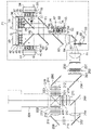
図1は本開示の実施の形態1における光源装置71の構成例を示すブロック図である。
(Embodiment 1)
FIG. 1 is a block diagram showing a configuration example of a
図1において、実施の形態1にかかる光源装置71は、第1の赤色レーザ光源33と、第2の赤色レーザ光源38と、第1の緑色レーザ光源43と、第2の緑色レーザ光源48と、第1の青色レーザ光源53と、第2の青色レーザ光源57とを備える。光源装置71はさらに、ヒートシンク34、39、44、49、58と、プレート型の偏光ビームスプリッタ59,60と、ミラー61と、赤反射のダイクロイックミラー62と、青反射のダイクロイックミラー63と、コンデンサレンズ64と、拡散板65と、ミラー66と、円形拡散板67とモーター68で構成されてレーザ光固有のスペックルを解消するための動的な拡散板である回転拡散板69とを備える。さらに、光源装置71の外側に、コンデンサレンズ70を備える。
1 , a
第1の赤色レーザ光源33は赤色半導体レーザ30とコリメートレンズ31と放熱板32を備えて構成される。第2の赤色レーザ光源38は赤色半導体レーザ35とコリメートレンズ36と放熱板37を備えて構成される。第1の緑色レーザ光源43は緑色半導体レーザ40とコリメートレンズ41と放熱板42を備えて構成される。第2の緑色レーザ光源48は緑色半導体レーザ45とコリメートレンズ46と放熱板47を備えて構成される。第1の青色レーザ光源53は青色半導体レーザ50と、コリメートレンズ51と放熱板52を備えて構成される。第2の青色レーザ光源57は、青色半導体レーザ54と、コリメートレンズ55と放熱板56を備えて構成される。
The first red
なお、図中において、各レーザ光源33,38,43,48,53,57から出射する光の偏光方向を示している。
In addition, in the figure, the polarization direction of the light emitted from each of the
第1の赤色レーザ光源33は、正方配置した24個(=6×4)の赤色半導体レーザ30及びその前面に配置したコリメートレンズ31を、放熱板32上に一定の間隔で2次元形状に配置して構成される。ここで、各赤色半導体レーザ30は、主波長が660nmの赤色光を発光し、S偏光の光を出射する。第2の赤色レーザ光源38は、正方配置した24個(=6×4)の赤色半導体レーザ35及びその前面に配置したコリメートレンズ36を、放熱板37上に一定の間隔で2次元形状に配置して構成される。ここで、各赤色半導体レーザ35は、主波長が640nmの赤色光を発光し、P偏光の光を出射する。波長分割方式立体表示のため、第1の赤色レーザ光源33の主波長と第2の赤色レーザ光源38の主波長との波長差を20nmとしている。赤色半導体レーザは一般に、630nm以下での発光は開発途上のため、短波長の赤色半導体レーザ35は640nmで発光する。
The first red
ヒートシンク34、39は赤色レーザ光源33、38を冷却するために設けられる。赤色半導体レーザ30、35から出射された各出力光は、対応するコリメートレンズ31、36により、それぞれ集光され平行な光束に変換された後、偏光ビームスプリッタ59に入射する。偏光ビームスプリッタ59は、赤色レーザ光源33からのS偏光を反射し、赤色レーザ光源38からのP偏光を透過する。偏光合成された赤色光は、ミラー61で反射した後、赤反射のダイクロイックミラー62に入射する。
第1の緑色レーザ光源43は、正方配置した24個(=6×4)個の緑色半導体レーザ40及びそれの前面に配置したコリメートレンズ41を、放熱板42上に一定の間隔で2次元形状に配置して構成される。ここで、各緑色半導体レーザ40は、主波長が530nmの緑色光を発光し、S偏光の光を出射する。第2の緑色レーザ光源48は、正方配置した24個(=6×4)の緑色半導体レーザ45及びそれの前面に配置したコリメートレンズ46を、放熱板47上に一定の間隔で2次元形状に配置して構成される。ここで、各緑色半導体レーザ45は、主波長が510nmの緑色光を発光し、P偏光の光を出射する。波長分割方式立体表示のため、第1の緑色レーザ光源43の主波長と第2の緑色レーザ光源48の主波長との波長差を20nmとしている。緑色半導体レーザは一般に、530nm以上での発光は開発途上であるため、長波長の緑色半導体レーザ40は530nmで発光する。
The first green
ヒートシンク44、49は緑色レーザ光源43、48を冷却するために設けられる。緑色半導体レーザ40、45から出射された各出力光は、対応するコリメートレンズ41、46により、それぞれ集光され平行な光束に変換された後、偏光ビームスプリッタ60に入射する。偏光ビームスプリッタ60は、緑色レーザ光源43からのS偏光を反射し、緑色レーザ光源48からのP偏光を透過する。偏光合成された緑色光は、赤反射のダイクロイックミラー62に入射する。赤反射のダイクロイックミラー62は、赤色レーザ光源33、38の光を反射し、緑色レーザ光源43、48の光を透過する。赤反射のダイクロイックミラー62からの光は、青反射のダイクロイックミラー63に入射する。
第1の青色レーザ光源53は、正方配置した8個(=4×2)の青色半導体レーザ50及びそれの前面に配置されたコリメートレンズ51を、放熱板52上に一定の間隔で2次元形状に配置して構成される。ここで、各青色半導体レーザ50は、主波長が465nmの青色光を発光し、S偏光を出射する。第2の青色レーザ光源57は、正方配置した8個(=4×2)の青色半導体レーザ54及びそれの前面に配置されたコリメートレンズ55を、放熱板56上に一定の間隔で2次元形状に配置して構成される。青色半導体レーザ54は、主波長が445nmの青色光を発光し、P偏光を出射する。波長分割方式立体表示のため、第1の青色レーザ光源53の主波長と第2の青色レーザ光源57の主波長との波長差は20nmである。ヒートシンク58は青色レーザ光源53、57を冷却するために設けられる。青色半導体レーザ50,54は、赤色及び緑色の半導体レーザ30,35,40,45に対して、発光効率が高いことや所望の白色光色度に必要な光出力が小さいため、1/3程度の半導体レーザ個数で構成している。青色半導体レーザ50,54から出射された各出力光は、対応するコリメートレンズ51、55により、それぞれ集光され平行な光束に変換された後、青反射のダイクロイックミラー63に入射する。
The first blue
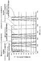
図2は、赤色、緑色、青色のレーザ光の発光スペクトルとダイクロイックミラーの分光特性を示すスペクトル図である。 FIG. 2 is a spectral diagram showing emission spectra of red, green, and blue laser light and spectral characteristics of a dichroic mirror.
図2において、発光スペクトルは各レーザ光のピーク強度100%とした場合の相対強度を示している。赤色、緑色、青色のレーザ光は、それぞれ2つの波長帯で発光する。それぞれの発光スペクトルの短波長側の光はP偏光の光であり、長波長側の光はS偏光の光である。赤反射のダイクロイックミラー62のP偏光及びS偏光の透過率と、青反射のダイクロイックミラー63のP偏光及びS偏光の透過率を示している。透過率が50%となる波長をカットオフ波長とすると、赤反射のダイクロイックミラー62のカットオフ波長は、S偏光で573nm、P偏光で600nmの特性を有する。また、青反射のダイクロイックミラー63のカットオフ波長は、S偏光で500nm、P偏光で478nmの特性を有する。
In FIG. 2, the emission spectrum shows the relative intensity when the peak intensity of each laser beam is 100%. The red, green, and blue laser lights each emit light in two wavelength bands. Light on the short wavelength side of each emission spectrum is P-polarized light, and light on the long wavelength side is S-polarized light. The transmittance of the red-reflecting
赤色のレーザ光の主波長640nm(P偏光)と660nm(S偏光)に対して、赤反射のダイクロイックミラー62のP偏光カットオフ波長が573nm、S偏光カットオフ波長が600nmであるため、赤色レーザ光を効率よく反射する。また、緑色レーザ光の主波長510nm(P偏光)、530nm(S偏光)に対して、赤反射のダイクロイックミラー62のP偏光カットオフ波長が573nm、S偏光カットオフ波長が600nmであるため、緑色レーザ光を効率よく透過する。
With respect to red laser beams with dominant wavelengths of 640 nm (P-polarized light) and 660 nm (S-polarized light), the red-reflecting
青色レーザ光の主波長445nm(P偏光)と465nm(S偏光)に対して、青反射のダイクロイックミラー63のP偏光カットオフ波長が478nm、S偏光カットオフ波長が500nmであるため、青色レーザ光を効率よく反射する。また、緑色レーザ光の主波長510nm(P偏光)、530nm(S偏光)に対して、青反射の青反射のダイクロイックミラー63のP偏光カットオフ波長が478nm、S偏光カットオフ波長が500nmであるため、緑色レーザ光を効率よく透過する。さらに、赤色レーザ光も効率よく透過する。赤反射のダイクロイックミラーについては、主波長とカットオフ波長の差が大きいため、赤色レーザ光の短波長側がS偏光、長波長側がP偏光であっても、従来技術に比較して効率よく反射する。
With respect to the dominant wavelengths of 445 nm (P-polarized light) and 465 nm (S-polarized light) of blue laser light, the blue-reflecting
図1において、青反射のダイクロイックミラー63を透過、反射した各レーザ光は、コンデンサレンズ64に入射する。コンデンサレンズ64は、各レーザ光が回転拡散板69の近傍で集光するように、そのレンズ形状を決めている。コンデンサレンズ64を透過したレーザ光は、拡散板65で拡散された後、ミラー66で反射し、回転拡散板69に入射する。拡散板65はガラス基板上に形成された微細なマイクロレンズをアレイ状に形成して拡散面を構成したものであり、入射する光を拡散する。マイクロレンズ形状とすることにより、フッ酸などの溶液を用いて、ガラス表面を微細な凹凸形状に加工する化学処理の拡散板よりも、最大拡がり角度を低減で拡散損失を低減できる。拡散光の最大強度の50%となる半値角度幅である拡散角度は略5度と小さく、偏光特性を保持する。光強度がピーク強度に対して13.5%となる直径をスポット径と定義すると、スポット径が3mm~5mmのスポット光に重畳され、回転拡散板69の近傍に入射する。拡散板65はそのスポット光の径が所望のスポット径となるよう光を拡散させている。
In FIG. 1 , each laser beam transmitted through and reflected by a blue reflecting
回転拡散板69は、ガラス基板上に円周状に拡散層を形成した円形拡散板67と、その中央部に設けられ円形拡散板67を回転するモーター68を備えて構成され、かつ円形拡散板67の回転制御が可能である。回転拡散板69は10,800rpm程度まで高速に回転可能である。拡散には化学処理の拡散板を用い、拡散角は略12度で、偏光特性を維持する。拡散面を回転することにより、レーザ光に起因するスクリーン上でのランダムな干渉パターンが時間的、空間的に高速変動して、スペックルノイズを解消することができる。また、レーザ光源の微小な発光サイズと発光数に起因する微小な輝度むらも低減することができる。
The
回転拡散板69により、多数の拡散角度で時間的に多重化された光は、コンデンサレンズ70で集光され、略平行光に変換される。コンデンサレンズ70は、回転拡散板69の近傍のスポット光を平行光となるように、その形状を決めている。
Light temporally multiplexed at a number of diffusion angles by the rotating
なお、実施の形態1において、赤反射のダイクロイックミラー62を緑反射のダイクロイックミラーとして、緑色のレーザ光源と赤色のレーザ光源の配置を変更してもよい。
In the first embodiment, the red-reflecting
また、実施の形態1において、拡散板65はマイクロレンズアレイの拡散板を用いて説明したが、集光効率はやや低下するが、安価な化学処理の拡散板を用いてもよい。
Further, in
さらに、実施の形態1において、赤色レーザ光源33,38と、緑色レーザ光源43,48、青色レーザ光源53,57はそれぞれ48個、48個、16個の半導体レーザ素子を配置した構成を示したが、高輝度化のため、さらに多数の半導体レーザを用いて構成してもよい。
Furthermore, in
以上のように、本実施の形態1にかかる光源装置71によれば、複数の波長帯を発光する赤色、緑色、青色のレーザ光源と、当該レーザ光源から光を合成するダイクロイックミラーと、回転拡散板とを備え、前記ダイクロイックミラーの1つは、青色を反射するダイクロイックミラーであって、前記複数の波長帯の青色と緑色のレーザ光は、短波長帯のレーザ光がP偏光、長波長帯のレーザ光がS偏光である。このため、図2を参照して詳述したように偏光特性の重なりを防止して損失を軽減でき、これにより、赤色、緑色、青色のレーザ光を小型で、かつ従来技術に比較して高い効率で合成することができる。
As described above, according to the
(実施の形態2)
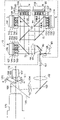
図3は実施の形態2にかかる光源装置73の構成例を示すブロック図である。
(Embodiment 2)
FIG. 3 is a block diagram showing a configuration example of the
図3において、実施の形態2にかかる光源装置73は、第1の赤色レーザ光源133と、第2の赤色レーザ光源138と、第1の緑色レーザ光源143と、第2の緑色レーザ光源148と、第1の青色レーザ光源153と、第2の青色レーザ光源157とを備えて構成される。第1の赤色レーザ光源133は、赤色半導体レーザ130とコリメートレンズ131と放熱板132を備えて構成される。第2の赤色レーザ光源138は、赤色半導体レーザ135とコリメートレンズ136と放熱板137を備えて構成される。第1の緑色レーザ光源143は、緑色半導体レーザ140とコリメートレンズ141と放熱板142を備えて構成される。第2の緑色レーザ光源148は、緑色半導体レーザ145とコリメートレンズ146と放熱板147を備えて構成される。第1の青色レーザ光源153は、青色半導体レーザ150と、コリメートレンズ151と放熱板152を備えて構成される。第2の青色レーザ光源157は、青色半導体レーザ154とコリメートレンズ155と放熱板156を備えて構成される。光源装置73はさらに、ヒートシンク134、139、144、149、158と、プレート型の偏光ビームスプリッタ59,60と、ミラー61と、赤反射のダイクロイックミラー62と、コンデンサレンズ64と、拡散板65と、ミラー66と、円形拡散板67とモーター68で構成された動的な拡散板である回転拡散板69とを備えて構成される。そして、光源装置73の外側に、コンデンサレンズ70とを備える。以上の光源装置73は、実施の形態1の光源装置71と同様な構成を有する。
3, the
実施の形態2にかかる図3の光源装置は、図1の光源装置に比較して、以下の点が異なる。
(1)青透過のダイクロイックミラー72を、青色レーザ光源157とコンデンサレンズ64との間に配置している。
(2)複数の波長帯を有する赤色、緑色、青色のレーザ光源133,138,143,148,153,157において、それぞれ短波長帯の発光がS偏光で、長波長帯の発光がP偏光である。
The light source device of FIG. 3 according to the second embodiment differs from the light source device of FIG. 1 in the following points.
(1) A blue-transmitting
(2) In the red, green, and blue
なお、図中において、各レーザ光源133,138,143,148,153,157から出射する光の偏光方向を示している。
In the drawing, the polarization directions of the light emitted from the
赤色半導体レーザ130は、主波長が640nmの赤色光を発光し、S偏光の光を出射する。赤色半導体レーザ135は、主波長が660nmの赤色光を発光し、P偏光の光を出射する。緑色半導体レーザ140は、主波長が510nmの緑色光を発光し、S偏光の光を出射する。緑色半導体レーザ145は、主波長が530nmの緑色光を発光し、P偏光の光を出射する。青色半導体レーザ150は、主波長が445nmの青色光を発光し、S偏光の光を出射する。青色半導体レーザ154は、主波長が465nmの青色光を発光し、P偏光の光を出射する。
The
赤反射のダイクロイックミラー62で合成された赤色、緑色のレーザ光は、青透過のダイクロイックミラー72に入射する。青色半導体レーザ150、154を出射した光は対応するコリメートレンズ151、155により、それぞれ集光され平行な光束に変換された後、青透過のダイクロイックミラー72に入射する。
The red and green laser beams synthesized by the red-reflecting
図4は、赤色、緑色、青色のレーザ光の発光スペクトルとダイクロイックミラーの分光特性を示すスペクトル図である。 FIG. 4 is a spectral diagram showing emission spectra of red, green, and blue laser beams and spectral characteristics of a dichroic mirror.
図4において、発光スペクトルはそれぞれのレーザ光のピーク強度100%とした場合の相対強度を示している。赤色、緑色、青色のレーザ光は、それぞれ2つの波長帯で発光する。それぞれの発光スペクトルの短波長側はS偏光の光であり、長波長側はP偏光の光である。赤反射のダイクロイックミラーのP偏光及びS偏光の透過率と、青透過のダイクロイックミラー72のP偏光及びS偏光の透過率を示している。透過率が50%となる波長をカットオフ波長とすると、赤反射のダイクロイックミラーのカットオフ波長は、S偏光で573nm、P偏光で600nmの特性を有する。また、青透過のダイクロイックミラー72のカットオフ波長は、P偏光で498nm、S偏光で475nmの特性を有する。青色レーザ光の主波長445nm(S偏光)と465nm(P偏光)に対して、青透過のダイクロイックミラー72のS偏光カットオフ波長が475nm、P偏光カットオフ波長が498nmであるため、青色レーザ光を効率よく透過する。また、緑色レーザ光の主波長510nm(S偏光)、530nm(P偏光)に対して、青透過のダイクロイックミラー72のS偏光カットオフ波長が475nm、P偏光カットオフ波長が498nmであるため、緑色レーザ光を効率よく反射する。さらに、赤色レーザ光も効率よく反射する。赤反射のダイクロイックミラーについては、主波長とカットオフ波長の差が大きいため、赤色レーザ光の短波長側がP偏光、長波長側がS偏光であっても、従来技術に比較して効率よく反射する。
In FIG. 4, the emission spectrum shows the relative intensity when the peak intensity of each laser beam is 100%. The red, green, and blue laser lights each emit light in two wavelength bands. The short wavelength side of each emission spectrum is S-polarized light, and the long wavelength side is P-polarized light. The transmittance of the red-reflecting dichroic mirror for P-polarized light and S-polarized light and the transmittance of the blue-transmitting
図3において、青透過のダイクロイックミラー72を透過、反射した各レーザ光は、コンデンサレンズ64に入射する。コンデンサレンズ64を透過したレーザ光は、拡散板65で拡散された後、ミラー66で反射し、回転拡散板69の近傍に集光する。拡散板の拡散角は略5度で、集光する光のスポット径は3mm~5mmである。
In FIG. 3 , each laser beam transmitted and reflected by a blue-transmitting
回転拡散板69は、ガラス基板上に円周状に拡散層を形成した円形拡散板67と、その中央部に設けられたモーター68とを備え、回転制御可能である。円形拡散板67の拡散角は略12度である。回転拡散板69の拡散面を回転することにより、レーザ光に起因にするスクリーン上でのランダムな干渉パターンが時間的、空間的に高速変動して、スペックルノイズを解消することができる。また、レーザ光源の微小な発光サイズと発光数に起因する微小な輝度むらも低減することができる。
The
回転拡散板69により、多数の拡散角度で時間的に多重化された光は、コンデンサレンズ70で集光され、略平行光に変換される。
Light temporally multiplexed at a number of diffusion angles by the rotating
以上の実施の形態2において、赤反射のダイクロイックミラー62を緑反射のダイクロイックミラーとして、緑色のレーザ光源と赤色のレーザ光源の配置を変更してもよい。
In the second embodiment described above, the red-reflecting
また、実施の形態2において、赤色レーザ光源133,138と、緑色レーザ光源143,148、青色レーザ光源153,157はそれぞれ、48個、48個、16個の半導体レーザ素子を配置した構成を示したが、高輝度化のため、さらに多数の半導体レーザを用いて構成してもよい。
In the second embodiment, the red laser
以上のように、本実施の形態2にかかる光源装置73によれば、複数の波長帯を発光する赤色、緑色、青色のレーザ光源と、レーザ光源から光を合成するダイクロイックミラーと、回転拡散板とを備え、前記ダイクロイックミラーの1つは、青色を透過するダイクロイックミラーであって、前記複数の波長帯の青色と緑色のレーザ光は、短波長帯のレーザ光がS偏光、長波長帯のレーザ光がP偏光である。このため、図4を参照して詳述したように偏光特性の重なりを防止して損失を軽減でき、これにより、赤色、緑色、青色のレーザ光を小型で、かつ従来技術に比較して高い効率で合成することができる。
As described above, according to the
(実施の形態3)
図5は、実施の形態3における投写型立体表示装置である。実施の形態3にかかる投写型立体表示装置は、以下のことを特徴とする。
(1)画像形成手段として、3つのDMD170,171,172を用いた。
(2)図1の光源装置71を用いた。
(Embodiment 3)
FIG. 5 shows a projection stereoscopic display device according to the third embodiment. The projection stereoscopic display device according to the third embodiment is characterized by the following.
(1) Three
(2) The
図5において、光源装置71から出射した光は、ロッド161へ集光する。ロッド161への入射光はロッド161内部で複数回反射することにより、光強度分布が均一化され出射する。ロッド161からの出射光はリレーレンズ162により集光され、反射ミラー163で反射した後、フィールドレンズ164を透過し、全反射プリズム165に入射する。全反射プリズム165は2つのプリズムを備えて構成され、互いのプリズムの近接面には薄い空気層166を形成している。空気層166は臨界角以上の角度で入射する光を全反射する。フィールドレンズ164からの光は全反射プリズム165の全反射面で反射されて、カラープリズム167に入射する。
In FIG. 5 , the light emitted from the
カラープリズム167は3つのプリズムからなり、それぞれのプリズムの近接面には青反射のダイクロイックミラー168と赤反射のダイクロイックミラー169が形成されている。カラープリズム167の青反射のダイクロイックミラー168と赤反射のダイクロイックミラー169により、青色、赤色、緑色の各色光に分離され、それぞれDMD170、171、172に入射する。DMD170、171、172は、時分割した立体表示の右目用映像信号と左目用映像信号に応じてマイクロミラーを偏向させ、投写レンズ173に入射する光と、投写レンズ173の有効外へ進む光とに反射させる。2つの波長帯をもつ赤色、緑色、青色のレーザ光は、立体表示の右目用映像信号にはそれぞれ短波長側の光を、左目用映像信号にはそれぞれ長波長側の光を対応させて、その強度を変調する。レーザ光源は高速駆動が可能なため、立体表示用の映像信号に追従する。
The
DMD170、171、172により反射された光は、再度カラープリズム167を透過する。カラープリズム167を透過する過程で、分離された青色、赤色、緑色の各色光は合成され、全反射プリズム165に入射する。全反射プリズム165に入射した光は空気層166に臨界角以下で入射するため、透過して、投写レンズ173に入射する。このようにして、DMD170、171、172により形成された画像光がスクリーン(図示せず)上に拡大投写される。スクリーン上に拡大投写された右目用と左目用画像は、右目用の光のみ、もしくは、左目用の光のみを透過するめがねを装着して、立体画像を鑑賞することができる。
Light reflected by the
図5の光源装置71(図1)は、複数の波長帯をもつ赤色、緑色、青色のレーザ光源を用いて、従来技術に比較して小型で、高い効率で、白色光を出射する。このため、小型、広色域で投写型立体表示装置を実現できる。画像形成手段にDMD171,172,173を用いているため、液晶を用いた画像形成手段と比べて、耐光性、耐熱性が高い投写型立体表示装置が構成できる。さらに、3つのDMD171,172,173を用いているため、従来技術に比較して色再現が良好で、明るく高精細な投写画像を得ることができる。
The
以上のように、本実施の形態3にかかる投写型立体表示装置によれば、光源装置71が、赤色、緑色、青色のレーザ光源と、各レーザ光源光を合成するダイクロイックミラーと、回転拡散板とを備え、複数の波長帯のレーザ光は、短波長側がP偏光、長波長側がS偏光であって、それぞれが互いに直交する偏光となるように構成している。このため、従来技術に比較して小型で、高効率な投写型立体表示装置が構成できる。
As described above, according to the projection-type stereoscopic display device according to the third embodiment, the
(実施の形態4)
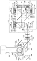
図6は、実施の形態4にかかる投写型立体表示装置の構成例を示すブロック図である。実施の形態4にかかる投写型立体表示装置は、以下の点を特徴としている。
(1)画像形成手段として、TNモードもしくはVAモードであって、画素領域に薄膜トランジスタを形成したアクティブマトリクス方式の透過型の液晶パネル217、218、219を用いた。
(2)図1の光源装置71を用いた。
(Embodiment 4)
FIG. 6 is a block diagram of a configuration example of a projection stereoscopic display device according to a fourth embodiment. The projection-type stereoscopic display device according to the fourth embodiment is characterized by the following points.
(1) As image forming means, TN mode or VA mode, active matrix transmissive
(2) The
図6の投写型立体表示装置において、コンデンサレンズ70以降の投写部は、第1のレンズアレイ板200と、第2のレンズアレイ板201と、偏光変換素子202と、重畳用レンズ203と、青反射のダイクロイックミラー204と、緑反射のダイクロイックミラー205と、反射ミラー206,207,208と、リレーレンズ209,210と、
フィールドレンズ211、212、213と、入射側偏光板214、215、216と、液晶パネル217、218、219と、出射側偏光板220、221、222と、赤反射のダイクロイックミラーと青反射のダイクロイックミラーを備えて構成される色合成プリズム223と、投写レンズ224とを備えて構成される。
In the projection-type stereoscopic display device of FIG. 6, the projection unit after the
図6において、光源装置71からの光はコンデンサレンズ70を介して、複数のレンズ素子を備えて構成される第1のレンズアレイ板200に入射する。第1のレンズアレイ板200に入射した光束は多数の光束に分割される。分割された多数の光束は、複数のレンズを備えて構成される第2のレンズアレイ板201に収束する。第1のレンズアレイ板200のレンズ素子は、液晶パネル217,218、219と相似形の開口形状である。第2のレンズアレイ板201のレンズ素子の焦点距離は、第1のレンズアレイ板200と液晶パネル217、218、219とが略共役関係となるように決められている。第2のレンズアレイ板201からの分割された光は、偏光変換素子202に入射する。偏光変換素子202は、偏光分離プリズムと1/2波長板により構成され、光源からのP偏光とS偏光の光を1つの偏光方向の光に変換する。
In FIG. 6, light from a
偏光変換素子202を出射した光は重畳用レンズ203に入射する。重畳用レンズ203は、第2のレンズアレイ板201の各レンズ素子からの出射した光を液晶パネル217、218、219上に重畳照明するために設けられる。第1のレンズアレイ板200及び第2のレンズアレイ板201と、重畳用レンズ203を照明光学系としている。重畳用レンズ203からの光は、色分離手段である青反射のダイクロイックミラー204、緑反射のダイクロイックミラー205により、青色、緑色、赤色の各色光に分離される。緑色光はフィールドレンズ211、入射側偏光板214を透過して、液晶パネル217に入射する。青色光は反射ミラー206で反射した後、フィールドレンズ212及び入射側偏光板215を透過して液晶パネル218に入射する。赤色光はリレーレンズ209、210や反射ミラー207、208を透過屈折及び反射して、フィールドレンズ213及び入射側偏光板216を透過して、液晶パネル219に入射する。
The light emitted from the
3枚の液晶パネル217、218、219は、時分割した立体表示の右目用映像信号と左目用映像信号に応じて、画素への印加電圧の制御により入射する光の偏光状態を変化させ、それぞれの液晶パネル217、218、219の両側に透過軸を直交するように配置したそれぞれの入射側偏光板214、215、216及び出射側偏光板220、221、222を組み合わせて光を変調し、緑、青、赤の画像を形成する。2つの波長帯をもつ赤色、緑色、青色のレーザ光は、立体表示の右目用映像信号にはそれぞれ短波長側の光を、左目用映像信号にはそれぞれ長波長側の光を対応させて、その強度を変調する。レーザ光源は高速駆動か可能なため、立体表示用の映像信号に追従する。
The three
出射側偏光板220、221、222を透過した各色光は色合成プリズム223により、赤色、青色の各色光がそれぞれ赤反射のダイクロイックミラー、青反射のダイクロイックミラーによって反射し、緑の色光と合成され、投写レンズ224に入射する。投写レンズ224に入射した光は、スクリーン(図示せず)上に拡大投写される。スクリーン上に拡大投写された右目用と左目用画像は、右目用の光のみ、もしくは、左目用の光のみを透過するめがねを装着して、立体画像を鑑賞することができる。
The color lights transmitted through the output-side
図6の光源装置71(図1)は、複数の波長帯をもつ赤色、緑色、青色のレーザ光源を用いて、小型で、高効率な白色光を出射する。このため、従来技術に比較して小型、広色域で投写型立体表示装置を実現できる。また、画像形成手段には、時分割方式ではなく偏光を利用する3枚の液晶パネル217、218、219を用いているため、カラーブレイキングがなく、従来技術に比較して色再現が良好で、明るく高精細な投写画像を得ることができる。また、3つのDMD171,172,173を用いた場合よりも、全反射プリズムが不要で、色合成プリズム223が45度入射の小型プリズムになるため、投写型立体表示装置が小型に構成できる。
The light source device 71 (FIG. 1 ) of FIG. 6 uses red, green, and blue laser light sources having a plurality of wavelength bands to emit white light with high efficiency in a small size. Therefore, it is possible to realize a projection-type stereoscopic display device that is smaller in size and has a wider color gamut than the conventional technology. In addition, since the three
以上のように、実施の形態4にかかる投写型立体表示装置によれば、その光源装置71が、赤色、緑色、青色のレーザ光源と、各レーザ光源光を合成するダイクロイックミラーと、回転拡散板とを備え、複数の波長帯のレーザ光は、短波長側がP偏光、長波長側がS偏光であって、それぞれが互いに直交する偏光となるように構成している。このため、従来技術に比較して小型で、高効率な投写型立体表示装置が構成できる。
As described above, according to the projection type stereoscopic display device according to the fourth embodiment, the
(実施の形態5)
図7は本発明の実施の形態5における投写型立体表示装置の構成例を示すブロック図である。実施の形態5にかかる投写型立体表示装置は、図5の投写型立体表示装置において、光源装置71に代えて、図3の光源装置73を備えたことを特徴とする。これにより、図3の実施の形態2にかかる作用効果を有するように構成でき、従来技術に比較して小型で、高効率な投写型立体表示装置が構成できる。
(Embodiment 5 )
FIG. 7 is a block diagram showing a configuration example of a projection stereoscopic display device according to Embodiment 5 of the present invention. The projection-type stereoscopic display device according to the fifth embodiment is characterized in that the projection-type stereoscopic display device shown in FIG. 5 is provided with a
(実施の形態6)
図8は本発明の実施の形態6における投写型立体表示装置の構成例を示すブロック図である。実施の形態6にかかる投写型立体表示装置は、図6の投写型立体表示装置において、光源装置71に代えて、図3の光源装置73を備えたことを特徴とする。これにより、図3の実施の形態2にかかる作用効果を有するように構成でき、従来技術に比較して小型で、高効率な投写型立体表示装置が構成できる。
(Embodiment 6 )
FIG. 8 is a block diagram showing a configuration example of a projection stereoscopic display device according to
(他の実施の形態)
以上のように、本出願において開示する技術の例示として、実施の形態を説明した。しかしながら、本開示における技術は、これに限定されず、適宜、変更、置き換え、付加、省略などを行った実施の形態にも適用可能である。また、上記実施の形態で説明した各構成要素を組み合わせて、新たな実施の形態とすることも可能である。
(Other embodiments)
As described above, the embodiment has been described as an example of the technology disclosed in the present application. However, the technology in the present disclosure is not limited to this, and can be applied to embodiments in which modifications, replacements, additions, omissions, etc. are made as appropriate. Further, it is also possible to combine the constituent elements described in the above embodiments to form a new embodiment.
そこで、以下、他の実施の形態を例示する。 Therefore, other embodiments will be exemplified below.
以上の実施の形態において、画像形成手段として、透過型の液晶パネルを用いたが、反射型の液晶パネルを用いて構成してもよい。反射型の液晶パネルを用いることにより、より小型で高精細な投写型立体表示装置が構成できる。 In the above embodiments, a transmissive liquid crystal panel is used as the image forming means, but a reflective liquid crystal panel may be used. By using a reflective liquid crystal panel, a smaller, higher-definition projection stereoscopic display device can be configured.
以上のように、本開示における技術の例示として、実施の形態を説明した。そのために、添付図面及び詳細な説明を提供した。 As described above, the embodiment has been described as an example of the technique of the present disclosure. To that end, the accompanying drawings and detailed description have been provided.
従って、添付図面及び詳細な説明に記載された構成要素の中には、課題解決のために必須な構成要素だけでなく、上記技術を例示するために、課題解決のためには必須でない構成要素も含まれ得る。そのため、それらの必須ではない構成要素が添付図面や詳細な説明に記載されていることをもって、直ちに、それらの必須ではない構成要素が必須であるとの認定をするべきではない。 Therefore, among the components described in the attached drawings and detailed description, there are not only components essential for solving the problem, but also components not essential for solving the problem in order to illustrate the above technology. can also be included. Therefore, it should not be immediately recognized that those non-essential components are essential just because they are described in the attached drawings and detailed description.
また、上述の実施の形態は、本開示における技術を例示するためのものであるから、特許請求の範囲またはその均等の範囲において種々の変更、置き換え、付加、省略などを行うことができる。 In addition, the above-described embodiments are intended to illustrate the technology of the present disclosure, and various modifications, replacements, additions, omissions, etc. can be made within the scope of the claims or equivalents thereof.
以上詳述したように、本開示によれば、複数の波長帯を発光するレーザ光源と、レーザ光源から光を合成するダイクロイックミラーと、動的拡散板とを備え、複数の波長帯のレーザ光は、短波長側と長波長側で互いに直交する偏光となるように構成しているため、広色域で小型、高効率な光源装置を構成できる。このため、広色域で、小型、高効率な投写型立体表示装置を実現できる。 As described in detail above, according to the present disclosure, a laser light source that emits light in a plurality of wavelength bands, a dichroic mirror that synthesizes light from the laser light source, and a dynamic diffusion plate are provided, and laser light in a plurality of wavelength bands is provided. is configured such that the short wavelength side and the long wavelength side are polarized orthogonal to each other, so that a compact, highly efficient light source device with a wide color gamut can be configured. Therefore, it is possible to realize a compact, highly efficient projection stereoscopic display device with a wide color gamut.
30、35、130、135 赤色半導体レーザ
31、36、41、46、51、55、131、136、141、151、155 コリメートレンズ
32、37、42、47、52、56、132、137、142、147、152、156 放熱板
33、38、133、138 赤色レーザ光源
34、39、44、49、58、134、139、144、149、158 ヒートシンク
40、45、140、145 緑色半導体レーザ
43、48、143、148 緑色レーザ光源
50、54、150、154 青色半導体レーザ
53、57、153、157 青色レーザ光源
59、60 偏光ビームスプリッタ
61、66 ミラー
62、169 赤反射のダイクロイックミラー
63、168、204 青反射のダイクロイックミラー
64、70 コンデンサレンズ
65 拡散板
67 円形拡散板
68 モーター
69 回転拡散板
71,73 光源装置
72 青透過のダイクロイックミラー
161 ロッド
162、209、210 リレーレンズ
163、206、207、208 反射ミラー
164、211、212、213 フィールドレンズ
165 全反射プリズム
166 空気層
167 カラープリズム
170、171、172 DMD(デジタルマイクロミラーデバイス)
173、224 投写レンズ
200 第1のレンズアレイ板
201 第2のレンズアレイ板
202 偏光変換素子
203 重畳用レンズ
205 緑反射のダイクロイックミラー
214、215、216 入射側偏光板
217、218、219 液晶パネル
220、221、222 出射側偏光板
223 色合成プリズム
30, 35, 130, 135
173, 224
Claims (8)
前記各色光を合成して出力する複数のダイクロイックミラーと、
前 記複数のダイクロイックミラーからの入射光を拡散する動的な拡散板と、を備えた光源装置であって、
前記ダイクロイックミラーの1つは青色を反射し、赤色光及び緑色光を透過するダイクロイックミラーであって、
前記複数のレーザ光源は青色レーザ光源を含み、
前記青色レーザ光源は、P偏光の短波長帯レーザ光と、当該短波長帯レーザ光よりも長い波長を有するS偏光の長波長帯レーザ光を発生する光源装置。 a plurality of laser light sources that emit light of each color in a plurality of wavelength bands;
a plurality of dichroic mirrors for synthesizing and outputting the respective color lights;,
Previous A light source device comprising: a dynamic diffusion plate that diffuses incident light from the plurality of dichroic mirrors,
One of the dichroic mirrors reflects blue lightand transmit red and green lightA dichroic mirror that
The plurality of laser light sources include blue laser light sources,
The blue laser light source is a light source device that generates a P-polarized short-wavelength laser beam and an S-polarized long-wavelength laser beam having a longer wavelength than the short-wavelength laser beam.
前記緑色レーザ光源は、P偏光の短波長帯のレーザ光と、当該短波長帯レーザ光よりも長い波長を有するS偏光の長波長帯のレーザ光を発生する請求項1記載の光源装置。 The plurality of laser light sources includes a green laser light source,
2. The light source device according to claim 1, wherein the green laser light source generates a P-polarized short-wavelength laser beam and an S-polarized long-wavelength laser beam having a longer wavelength than the short-wavelength laser beam.
前記円形拡散板を回転するモーターと、を備えた、回転拡散板である請求項1~4のうちのいずれか1つに記載の 光源装置。 The diffusion plate includes a circular diffusion plate configured by forming fine irregularities in a circular shape on the surface of a glass substrate;
and a motor that rotates the circular diffuser plate. Light source device.
前記光源装置からの光を集光して被照明領域に照明する照明光学系と、 an illumination optical system that collects light from the light source device and illuminates an area to be illuminated;
映像信号に従って画像を前記被照明領域に形成する画像形成素子と、 an image forming element that forms an image on the illuminated area according to a video signal;
前記画像形成素子で形成された画像を拡大投写する投写レンズとを備えた投写型立体表 and a projection lens for enlarging and projecting the image formed by the image forming element.
示装置。display device.
Priority Applications (2)
| Application Number | Priority Date | Filing Date | Title |
|---|---|---|---|
| JP2018119640A JP7108840B2 (en) | 2018-06-25 | 2018-06-25 | Light source device and projection stereoscopic display device |
| US16/448,494 US10819961B2 (en) | 2018-06-25 | 2019-06-21 | Light source apparatus for use in projection three-dimensional display apparatus, with dynamic diffusion plate |
Applications Claiming Priority (1)
| Application Number | Priority Date | Filing Date | Title |
|---|---|---|---|
| JP2018119640A JP7108840B2 (en) | 2018-06-25 | 2018-06-25 | Light source device and projection stereoscopic display device |
Publications (3)
| Publication Number | Publication Date |
|---|---|
| JP2020003519A JP2020003519A (en) | 2020-01-09 |
| JP2020003519A5 JP2020003519A5 (en) | 2020-09-10 |
| JP7108840B2 true JP7108840B2 (en) | 2022-07-29 |
Family
ID=68982269
Family Applications (1)
| Application Number | Title | Priority Date | Filing Date |
|---|---|---|---|
| JP2018119640A Active JP7108840B2 (en) | 2018-06-25 | 2018-06-25 | Light source device and projection stereoscopic display device |
Country Status (2)
| Country | Link |
|---|---|
| US (1) | US10819961B2 (en) |
| JP (1) | JP7108840B2 (en) |
Families Citing this family (11)
| Publication number | Priority date | Publication date | Assignee | Title |
|---|---|---|---|---|
| JPWO2018211886A1 (en) * | 2017-05-19 | 2020-03-19 | ソニー株式会社 | Projection display device |
| CN109188700B (en) * | 2018-10-30 | 2021-05-11 | 京东方科技集团股份有限公司 | Optical display system and AR/VR display device |
| CN110673430A (en) * | 2019-10-11 | 2020-01-10 | 山西汉威激光科技股份有限公司 | Large-color-gamut laser light source system integrated through trapped wave beam combination |
| CN113219773B (en) * | 2020-02-05 | 2023-03-24 | 中强光电股份有限公司 | Light source module and projection device |
| JP2021135333A (en) * | 2020-02-25 | 2021-09-13 | パナソニックIpマネジメント株式会社 | Light source device and projection-type display device |
| CN113433781B (en) * | 2020-03-23 | 2022-12-02 | 苏州佳世达光电有限公司 | Laser light-combining module |
| CN113534588B (en) * | 2020-04-21 | 2022-06-28 | 青岛海信激光显示股份有限公司 | Laser and projection apparatus |
| EP4168708A1 (en) * | 2020-06-23 | 2023-04-26 | Luminus, Inc. | Light-emitting systems including dual primary red leds |
| JP2022071342A (en) * | 2020-10-28 | 2022-05-16 | パナソニックIpマネジメント株式会社 | Light source device and projection display device |
| JP2022131795A (en) | 2021-02-26 | 2022-09-07 | セイコーエプソン株式会社 | Light source device and projector |
| TWI808722B (en) * | 2022-04-13 | 2023-07-11 | 明基電通股份有限公司 | Light mixing module and laser projector having the same |
Citations (2)
| Publication number | Priority date | Publication date | Assignee | Title |
|---|---|---|---|---|
| JP2014163974A (en) | 2013-02-21 | 2014-09-08 | Seiko Epson Corp | Light source device and projector |
| US20170115554A1 (en) | 2014-04-04 | 2017-04-27 | Barco Nv | Laser projection illumination system |
Family Cites Families (12)
| Publication number | Priority date | Publication date | Assignee | Title |
|---|---|---|---|---|
| US6715901B2 (en) * | 2002-08-15 | 2004-04-06 | Shi-Hwa Huang | Image projector system having a light source that includes at least four light emitting diode modules |
| JP3610977B2 (en) | 2003-04-21 | 2005-01-19 | セイコーエプソン株式会社 | Illumination device and projection device |
| US7159987B2 (en) | 2003-04-21 | 2007-01-09 | Seiko Epson Corporation | Display device, lighting device and projector |
| JP2005173625A (en) | 2005-01-06 | 2005-06-30 | Seiko Epson Corp | Lighting system and projection device |
| DE102006054713B4 (en) | 2006-11-19 | 2012-08-30 | Infitec Gmbh | Stereo projection with interference filters |
| EP2282231A3 (en) * | 2009-08-07 | 2011-05-04 | JDS Uniphase Corporation | Multi-segment optical retarder for creating 3d images |
| JP5527058B2 (en) * | 2010-07-06 | 2014-06-18 | セイコーエプソン株式会社 | Light source device and projector |
| CN107135389B (en) | 2011-03-14 | 2019-10-01 | 杜比实验室特许公司 | Laser display system, 3D viewing glasses and 3D rendering preparation method |
| JP5842162B2 (en) | 2011-03-23 | 2016-01-13 | パナソニックIpマネジメント株式会社 | Light source device and image display device using the same |
| US8746888B2 (en) | 2011-10-03 | 2014-06-10 | Eastman Kodak Company | Stereoscopic projector using spectrally-adjacent color bands |
| CN103207509B (en) | 2012-01-12 | 2015-06-24 | 三菱电机株式会社 | Light Source Device And Projecting Display Device |
| JP6186987B2 (en) | 2013-07-26 | 2017-08-30 | セイコーエプソン株式会社 | Light source unit and projection display device |
-
2018
- 2018-06-25 JP JP2018119640A patent/JP7108840B2/en active Active
-
2019
- 2019-06-21 US US16/448,494 patent/US10819961B2/en active Active
Patent Citations (2)
| Publication number | Priority date | Publication date | Assignee | Title |
|---|---|---|---|---|
| JP2014163974A (en) | 2013-02-21 | 2014-09-08 | Seiko Epson Corp | Light source device and projector |
| US20170115554A1 (en) | 2014-04-04 | 2017-04-27 | Barco Nv | Laser projection illumination system |
Also Published As
| Publication number | Publication date |
|---|---|
| JP2020003519A (en) | 2020-01-09 |
| US20190394429A1 (en) | 2019-12-26 |
| US10819961B2 (en) | 2020-10-27 |
Similar Documents
| Publication | Publication Date | Title |
|---|---|---|
| JP7108840B2 (en) | Light source device and projection stereoscopic display device | |
| JP5350610B2 (en) | Optical system for projector and corresponding projector | |
| JP5164421B2 (en) | Color separation / synthesis optical system and image projection apparatus using the same | |
| JP7065273B2 (en) | Light source device and projection type display device | |
| JP5391662B2 (en) | Stereoscopic image display apparatus, polarization separation / synthesis apparatus, stereoscopic image display method | |
| US9261770B2 (en) | Apparatus and method for combining laser beams of different polarization | |
| TW201007334A (en) | Laser illuminated micro-mirror projector | |
| JP5476946B2 (en) | 3D image projector | |
| JP4183663B2 (en) | Illumination device and projection display device | |
| US11215910B2 (en) | Light source device and projection display apparatus having a laser optical system, a fluorescence optical system, and a light combiner | |
| US9529247B2 (en) | Projector including polarization separation element and rotating prism | |
| JP7113225B2 (en) | Light source device and projection display device | |
| JP7113172B2 (en) | Light source device and projection display device | |
| JP2001005097A (en) | Reflection type color projector | |
| CN111983878B (en) | Optical rotating device, illumination system, and projection device | |
| JPWO2014132675A1 (en) | Image projection device | |
| JP2020197621A (en) | Light source device and projection type display device | |
| JP2019184947A (en) | Light source device and projection type display device | |
| JP3591026B2 (en) | Illumination device and projection display device using the same | |
| JP7129607B2 (en) | Light source device and projection display device | |
| JP2000305045A (en) | Picture projection device and picture observation device | |
| WO2022092009A1 (en) | Light source device and projection-type display device | |
| JP7329731B2 (en) | Light source device and projection display device | |
| US20210405517A1 (en) | Light source device and projection display apparatus | |
| JP2021135333A (en) | Light source device and projection-type display device |
Legal Events
| Date | Code | Title | Description |
|---|---|---|---|
| A521 | Request for written amendment filed |
Free format text: JAPANESE INTERMEDIATE CODE: A523 Effective date: 20190627 |
|
| A521 | Request for written amendment filed |
Free format text: JAPANESE INTERMEDIATE CODE: A523 Effective date: 20200727 |
|
| A621 | Written request for application examination |
Free format text: JAPANESE INTERMEDIATE CODE: A621 Effective date: 20210303 |
|
| A977 | Report on retrieval |
Free format text: JAPANESE INTERMEDIATE CODE: A971007 Effective date: 20211215 |
|
| A131 | Notification of reasons for refusal |
Free format text: JAPANESE INTERMEDIATE CODE: A131 Effective date: 20220105 |
|
| A521 | Request for written amendment filed |
Free format text: JAPANESE INTERMEDIATE CODE: A523 Effective date: 20220228 |
|
| TRDD | Decision of grant or rejection written | ||
| A01 | Written decision to grant a patent or to grant a registration (utility model) |
Free format text: JAPANESE INTERMEDIATE CODE: A01 Effective date: 20220315 |
|
| A61 | First payment of annual fees (during grant procedure) |
Free format text: JAPANESE INTERMEDIATE CODE: A61 Effective date: 20220413 |
|
| R151 | Written notification of patent or utility model registration |
Ref document number: 7108840 Country of ref document: JP Free format text: JAPANESE INTERMEDIATE CODE: R151 |