JP7097351B2 - Implant - Google Patents
Implant Download PDFInfo
- Publication number
- JP7097351B2 JP7097351B2 JP2019510584A JP2019510584A JP7097351B2 JP 7097351 B2 JP7097351 B2 JP 7097351B2 JP 2019510584 A JP2019510584 A JP 2019510584A JP 2019510584 A JP2019510584 A JP 2019510584A JP 7097351 B2 JP7097351 B2 JP 7097351B2
- Authority
- JP
- Japan
- Prior art keywords
- bridge
- lock
- implant
- distant
- tether
- Prior art date
- Legal status (The legal status is an assumption and is not a legal conclusion. Google has not performed a legal analysis and makes no representation as to the accuracy of the status listed.)
- Active
Links
Images


Classifications
-
- A—HUMAN NECESSITIES
- A61—MEDICAL OR VETERINARY SCIENCE; HYGIENE
- A61F—FILTERS IMPLANTABLE INTO BLOOD VESSELS; PROSTHESES; DEVICES PROVIDING PATENCY TO, OR PREVENTING COLLAPSING OF, TUBULAR STRUCTURES OF THE BODY, e.g. STENTS; ORTHOPAEDIC, NURSING OR CONTRACEPTIVE DEVICES; FOMENTATION; TREATMENT OR PROTECTION OF EYES OR EARS; BANDAGES, DRESSINGS OR ABSORBENT PADS; FIRST-AID KITS
- A61F2/00—Filters implantable into blood vessels; Prostheses, i.e. artificial substitutes or replacements for parts of the body; Appliances for connecting them with the body; Devices providing patency to, or preventing collapsing of, tubular structures of the body, e.g. stents
- A61F2/02—Prostheses implantable into the body
- A61F2/24—Heart valves ; Vascular valves, e.g. venous valves; Heart implants, e.g. passive devices for improving the function of the native valve or the heart muscle; Transmyocardial revascularisation [TMR] devices; Valves implantable in the body
- A61F2/2442—Annuloplasty rings or inserts for correcting the valve shape; Implants for improving the function of a native heart valve
- A61F2/2451—Inserts in the coronary sinus for correcting the valve shape
-
- A—HUMAN NECESSITIES
- A61—MEDICAL OR VETERINARY SCIENCE; HYGIENE
- A61B—DIAGNOSIS; SURGERY; IDENTIFICATION
- A61B17/00—Surgical instruments, devices or methods, e.g. tourniquets
- A61B17/04—Surgical instruments, devices or methods, e.g. tourniquets for suturing wounds; Holders or packages for needles or suture materials
- A61B17/0467—Instruments for cutting sutures
-
- A—HUMAN NECESSITIES
- A61—MEDICAL OR VETERINARY SCIENCE; HYGIENE
- A61B—DIAGNOSIS; SURGERY; IDENTIFICATION
- A61B17/00—Surgical instruments, devices or methods, e.g. tourniquets
- A61B17/00234—Surgical instruments, devices or methods, e.g. tourniquets for minimally invasive surgery
-
- A—HUMAN NECESSITIES
- A61—MEDICAL OR VETERINARY SCIENCE; HYGIENE
- A61B—DIAGNOSIS; SURGERY; IDENTIFICATION
- A61B17/00—Surgical instruments, devices or methods, e.g. tourniquets
- A61B17/04—Surgical instruments, devices or methods, e.g. tourniquets for suturing wounds; Holders or packages for needles or suture materials
- A61B17/0487—Suture clamps, clips or locks, e.g. for replacing suture knots; Instruments for applying or removing suture clamps, clips or locks
-
- A—HUMAN NECESSITIES
- A61—MEDICAL OR VETERINARY SCIENCE; HYGIENE
- A61F—FILTERS IMPLANTABLE INTO BLOOD VESSELS; PROSTHESES; DEVICES PROVIDING PATENCY TO, OR PREVENTING COLLAPSING OF, TUBULAR STRUCTURES OF THE BODY, e.g. STENTS; ORTHOPAEDIC, NURSING OR CONTRACEPTIVE DEVICES; FOMENTATION; TREATMENT OR PROTECTION OF EYES OR EARS; BANDAGES, DRESSINGS OR ABSORBENT PADS; FIRST-AID KITS
- A61F2/00—Filters implantable into blood vessels; Prostheses, i.e. artificial substitutes or replacements for parts of the body; Appliances for connecting them with the body; Devices providing patency to, or preventing collapsing of, tubular structures of the body, e.g. stents
- A61F2/02—Prostheses implantable into the body
- A61F2/24—Heart valves ; Vascular valves, e.g. venous valves; Heart implants, e.g. passive devices for improving the function of the native valve or the heart muscle; Transmyocardial revascularisation [TMR] devices; Valves implantable in the body
- A61F2/2442—Annuloplasty rings or inserts for correcting the valve shape; Implants for improving the function of a native heart valve
- A61F2/2466—Delivery devices therefor
-
- A—HUMAN NECESSITIES
- A61—MEDICAL OR VETERINARY SCIENCE; HYGIENE
- A61M—DEVICES FOR INTRODUCING MEDIA INTO, OR ONTO, THE BODY; DEVICES FOR TRANSDUCING BODY MEDIA OR FOR TAKING MEDIA FROM THE BODY; DEVICES FOR PRODUCING OR ENDING SLEEP OR STUPOR
- A61M25/00—Catheters; Hollow probes
- A61M25/01—Introducing, guiding, advancing, emplacing or holding catheters
-
- A—HUMAN NECESSITIES
- A61—MEDICAL OR VETERINARY SCIENCE; HYGIENE
- A61B—DIAGNOSIS; SURGERY; IDENTIFICATION
- A61B17/00—Surgical instruments, devices or methods, e.g. tourniquets
- A61B17/22—Implements for squeezing-off ulcers or the like on the inside of inner organs of the body; Implements for scraping-out cavities of body organs, e.g. bones; Calculus removers; Calculus smashing apparatus; Apparatus for removing obstructions in blood vessels, not otherwise provided for
- A61B17/221—Gripping devices in the form of loops or baskets for gripping calculi or similar types of obstructions
-
- A—HUMAN NECESSITIES
- A61—MEDICAL OR VETERINARY SCIENCE; HYGIENE
- A61B—DIAGNOSIS; SURGERY; IDENTIFICATION
- A61B17/00—Surgical instruments, devices or methods, e.g. tourniquets
- A61B17/32—Surgical cutting instruments
- A61B17/320016—Endoscopic cutting instruments, e.g. arthroscopes, resectoscopes
-
- A—HUMAN NECESSITIES
- A61—MEDICAL OR VETERINARY SCIENCE; HYGIENE
- A61B—DIAGNOSIS; SURGERY; IDENTIFICATION
- A61B17/00—Surgical instruments, devices or methods, e.g. tourniquets
- A61B17/32—Surgical cutting instruments
- A61B17/3201—Scissors
-
- A—HUMAN NECESSITIES
- A61—MEDICAL OR VETERINARY SCIENCE; HYGIENE
- A61B—DIAGNOSIS; SURGERY; IDENTIFICATION
- A61B17/00—Surgical instruments, devices or methods, e.g. tourniquets
- A61B17/00234—Surgical instruments, devices or methods, e.g. tourniquets for minimally invasive surgery
- A61B2017/00238—Type of minimally invasive operation
- A61B2017/00243—Type of minimally invasive operation cardiac
-
- A—HUMAN NECESSITIES
- A61—MEDICAL OR VETERINARY SCIENCE; HYGIENE
- A61B—DIAGNOSIS; SURGERY; IDENTIFICATION
- A61B17/00—Surgical instruments, devices or methods, e.g. tourniquets
- A61B17/00234—Surgical instruments, devices or methods, e.g. tourniquets for minimally invasive surgery
- A61B2017/00292—Surgical instruments, devices or methods, e.g. tourniquets for minimally invasive surgery mounted on or guided by flexible, e.g. catheter-like, means
-
- A—HUMAN NECESSITIES
- A61—MEDICAL OR VETERINARY SCIENCE; HYGIENE
- A61B—DIAGNOSIS; SURGERY; IDENTIFICATION
- A61B17/00—Surgical instruments, devices or methods, e.g. tourniquets
- A61B17/00234—Surgical instruments, devices or methods, e.g. tourniquets for minimally invasive surgery
- A61B2017/00358—Snares for grasping
-
- A—HUMAN NECESSITIES
- A61—MEDICAL OR VETERINARY SCIENCE; HYGIENE
- A61B—DIAGNOSIS; SURGERY; IDENTIFICATION
- A61B17/00—Surgical instruments, devices or methods, e.g. tourniquets
- A61B17/04—Surgical instruments, devices or methods, e.g. tourniquets for suturing wounds; Holders or packages for needles or suture materials
- A61B2017/0496—Surgical instruments, devices or methods, e.g. tourniquets for suturing wounds; Holders or packages for needles or suture materials for tensioning sutures
-
- A—HUMAN NECESSITIES
- A61—MEDICAL OR VETERINARY SCIENCE; HYGIENE
- A61F—FILTERS IMPLANTABLE INTO BLOOD VESSELS; PROSTHESES; DEVICES PROVIDING PATENCY TO, OR PREVENTING COLLAPSING OF, TUBULAR STRUCTURES OF THE BODY, e.g. STENTS; ORTHOPAEDIC, NURSING OR CONTRACEPTIVE DEVICES; FOMENTATION; TREATMENT OR PROTECTION OF EYES OR EARS; BANDAGES, DRESSINGS OR ABSORBENT PADS; FIRST-AID KITS
- A61F2230/00—Geometry of prostheses classified in groups A61F2/00 - A61F2/26 or A61F2/82 or A61F9/00 or A61F11/00 or subgroups thereof
- A61F2230/0002—Two-dimensional shapes, e.g. cross-sections
- A61F2230/0028—Shapes in the form of latin or greek characters
- A61F2230/0045—Omega-shaped
-
- A—HUMAN NECESSITIES
- A61—MEDICAL OR VETERINARY SCIENCE; HYGIENE
- A61F—FILTERS IMPLANTABLE INTO BLOOD VESSELS; PROSTHESES; DEVICES PROVIDING PATENCY TO, OR PREVENTING COLLAPSING OF, TUBULAR STRUCTURES OF THE BODY, e.g. STENTS; ORTHOPAEDIC, NURSING OR CONTRACEPTIVE DEVICES; FOMENTATION; TREATMENT OR PROTECTION OF EYES OR EARS; BANDAGES, DRESSINGS OR ABSORBENT PADS; FIRST-AID KITS
- A61F2250/00—Special features of prostheses classified in groups A61F2/00 - A61F2/26 or A61F2/82 or A61F9/00 or A61F11/00 or subgroups thereof
- A61F2250/0058—Additional features; Implant or prostheses properties not otherwise provided for
- A61F2250/0065—Additional features; Implant or prostheses properties not otherwise provided for telescopic
-
- A—HUMAN NECESSITIES
- A61—MEDICAL OR VETERINARY SCIENCE; HYGIENE
- A61M—DEVICES FOR INTRODUCING MEDIA INTO, OR ONTO, THE BODY; DEVICES FOR TRANSDUCING BODY MEDIA OR FOR TAKING MEDIA FROM THE BODY; DEVICES FOR PRODUCING OR ENDING SLEEP OR STUPOR
- A61M25/00—Catheters; Hollow probes
- A61M25/01—Introducing, guiding, advancing, emplacing or holding catheters
- A61M2025/0175—Introducing, guiding, advancing, emplacing or holding catheters having telescopic features, interengaging nestable members movable in relations to one another
Landscapes
- Health & Medical Sciences (AREA)
- Life Sciences & Earth Sciences (AREA)
- Cardiology (AREA)
- General Health & Medical Sciences (AREA)
- Public Health (AREA)
- Biomedical Technology (AREA)
- Heart & Thoracic Surgery (AREA)
- Engineering & Computer Science (AREA)
- Animal Behavior & Ethology (AREA)
- Veterinary Medicine (AREA)
- Surgery (AREA)
- Transplantation (AREA)
- Oral & Maxillofacial Surgery (AREA)
- Vascular Medicine (AREA)
- Nuclear Medicine, Radiotherapy & Molecular Imaging (AREA)
- Medical Informatics (AREA)
- Molecular Biology (AREA)
- Biophysics (AREA)
- Pulmonology (AREA)
- Anesthesiology (AREA)
- Hematology (AREA)
- Prostheses (AREA)
- Surgical Instruments (AREA)
Description
本特許出願は、2016年5月6日になされた米国仮特許出願第62/332754号に基づく優先権を主張し、その内容を、参照として任意の目的のためにここに明示的に組み込む。 This patent application claims priority under US Provisional Patent Application No. 62/332754 filed May 6, 2016, the contents of which are expressly incorporated herein by reference.
本開示は、張力要素(例えば、テザー)を冠状静脈洞内に配置して僧帽弁環状形成を行ない、僧帽弁逆流の治療を行う環状形成技術及び装置に関する。 The present disclosure relates to ring forming techniques and devices in which a tension element (eg, tether) is placed in a coronary sinus to perform mitral valve annulus formation and to treat mitral valve regurgitation.
僧帽弁逆流は、原発性弁欠陥(例えば、損傷した弁小葉)あるいは小葉接合を損なう機能的な欠陥によって生じる一般的な心臓弁障害である。機能的な僧帽弁逆流の一般的な原因は、心筋梗塞、慢性心筋虚血症、高血圧、心筋炎あるいは心筋損傷の他の原因によって生じた拡張型心筋症である。僧帽弁環及び左心室内腔の拡大は、根本的な筋疾患を更に悪化させ、弁閉鎖不全を悪化させる容量過負荷を起こす僧帽弁不全を引き起こす。僧帽弁修復は、僧帽弁逆流を低減し、続発性僧帽弁環の拡大を修正して、僧帽弁小葉接合を改善する。その修復技術の一つは、環状形成であり、弁環の周囲にリングを配置することで弁環を外科的に再構築あるいは増補し、その周辺及び外側中隔の寸法を縮小する。うっ血性心不全及び続発性僧帽弁逆流を有する患者に対して、環状形成は長期的な症候性及び生存の利点を与えることができる。 Mitral regurgitation is a common heart valve disorder caused by a primary valve defect (eg, a damaged valve leaflet) or a functional defect that impairs lobular junction. A common cause of functional mitral regurgitation is dilated cardiomyopathy caused by myocardial infarction, chronic myocardial ischemia, hypertension, myocarditis or other causes of myocardial damage. Enlargement of the mitral valve annulus and the left ventricular cavity causes mitral valve insufficiency, which causes volume overload, further exacerbating the underlying muscular disease and exacerbating valve insufficiency. Mitral valve repair reduces mitral valve regurgitation, corrects secondary mitral valve annulus enlargement, and improves mitral valve lobular junction. One of the repair techniques is ring formation, in which a ring is placed around the annulus to surgically reconstruct or augment the annulus and reduce the dimensions of its perimeter and lateral septum. For patients with congestive heart failure and secondary mitral regurgitation, ring formation can provide long-term symptomatic and survival benefits.
従来の僧帽弁環状形成は、胸骨切開あるいは開胸、及び心停止及び心肺バイパスを含む心臓切開手術を要する。例えば、環状形成は、僧帽弁環の左心房側面に人工環状形成リングを取り付けることで、弁環の有効寸法を縮小する外科的切開を介して環状形成行われる。様々な頑丈で柔軟性のある環状形成リングがこの目的のために開発され、例えば、米国特許第4917698、5041130、5061277、5064431、5104407、5201880及び5350420号に開示されている。非常に有効ではあるが、この心臓切開処置は、相当な病的状態及び長期の回復期を伴う。その結果、手術の危険度と病的状態とが適正であると判断するのに不十分な症状の患者、あるいは高度に進展した症状の患者、あるいは相当に共病的状態の患者には、しばしば避けられてきた。 Traditional mitral valvuloplasty requires sternotomy or thoracotomy, and cardiotomy surgery including cardiac arrest and cardiopulmonary bypass. For example, annulus formation is performed via a surgical incision that reduces the effective size of the annulus by attaching an artificial annulus ring to the side of the left atrium of the mitral annulus. A variety of sturdy and flexible annular forming rings have been developed for this purpose and are disclosed, for example, in US Pat. Nos. 4,917,698, 5041130, 5061277, 5064431, 51040407, 521880 and 5350420. Although very effective, this cardiotomy procedure is associated with considerable morbidity and a long recovery period. As a result, it is often the case for patients with symptoms that are inadequate to determine that the risk and morbidity of surgery are appropriate, or for patients with highly advanced symptoms, or patients with fairly comorbidity. It has been avoided.
心臓切開処置の臨床的不利益を低減するため、僧帽弁修復について経皮的なアプローチが開発されている。ある経皮的な技術では、プロテーゼが、カテーテル内で対象の血管系を通って、僧帽弁の周辺へと進んでいく。これらの経皮的な技術は、心臓切開手術または体外循環を要しないので、従来の外科治療に対する魅力的な代替であり、閉鎖して鼓動している心臓内に用いることができる。その治療は、潜在的にそれほど病的でなく、それほど深刻でない弁の機能障害を有する患者を含む広範囲の患者に適用可能である。 Percutaneous approaches to mitral valve repair have been developed to reduce the clinical disadvantages of cardiotomy procedures. In one percutaneous technique, the prosthesis travels within the catheter through the subject's vasculature to the periphery of the mitral valve. Since these percutaneous techniques do not require cardiotomy or extracorporeal circulation, they are an attractive alternative to conventional surgical treatment and can be used in a closed and beating heart. The treatment is applicable to a wide range of patients, including those with potentially less pathological and less severe valve dysfunction.
経皮的な僧帽弁修復処置の例は、冠状静脈洞短縮装置、トランスカメラル固定物、心室内環状ひだ形成、及び直接的小葉ステープリングが挙げられる。冠状静脈洞環状形成技術は、例えば、米国特許第6402781及び7090695、並びに米国特許公開公報第2004/0254600、2005/0027351及び2007/0073391号に開示される。あるトランス静脈洞アプローチは、冠状静脈洞へプロテーゼを導入して、後部の僧帽弁環の円周を縮小させるか、後部も僧帽弁環を前尖に向かって移動させる力を作用させることで僧帽弁接合を改善することを図るものである。冠状静脈洞法は、僧帽弁環に対する冠状静脈洞の近接を利用し、環の直径を縮小するため、冠状静脈洞内のプロテーゼの圧力が、繊維環あるいは近傍の心房壁を内側に押すようにする。 Examples of percutaneous mitral valve repair procedures include coronary sinus shortening devices, transcamera fixations, intraventricular ring fold formation, and direct lobular stapling. The coronary sinus ring formation technique is disclosed, for example, in US Pat. Nos. 6,402,781 and 7090695, as well as US Patent Publication Nos. 2004/0254600, 2005/0027351 and 2007/0073391. One transvenous sinus approach introduces a prosthesis into the coronary sinus to reduce the circumference of the posterior mitral annulus, or to exert a force that also moves the posterior mitral annulus toward the anterior leaflet. The purpose is to improve the mitral valve joint. The coronary sinus method utilizes the proximity of the coronary sinus to the mitral valve annulus and reduces the diameter of the ring so that the pressure of the prosthesis in the coronary sinus pushes the annulus fibrosus inward. To.
しかしながら、これらの技術は、有効な外科的リング環状形成を特徴づける円周方向の張力の確立においてのみ限定的な成功を示すものである。静脈洞短縮装置は、僧帽弁の交連に渡る局部的な短縮のみを生じさせ、機能的な僧帽弁逆流を特徴づける外側中隔分離を十分に縮小しない。小葉処置は、環の拡張を低減することができず、量の範囲及び変力状態の範囲を適合させる僧帽弁接合の正常な動的ラインをさらに害する場合がある。 However, these techniques show limited success only in establishing the circumferential tension that characterizes effective surgical ring ring formation. The sinus shortening device produces only local shortening across the commissure of the mitral valve and does not sufficiently reduce the lateral septal separation that characterizes functional mitral regurgitation. Leaflet treatment cannot reduce ring dilation and may further impair the normal dynamic line of mitral valve junctions that adapt the range of quantities and the range of inotropic states.
経皮的な環状形成についてのより最近の改善は、可動のガイドワイヤあるいは挿管カテーテル等のカテーテルを用いて僧帽弁環の周囲に張力材料を配置する冠状静脈洞経カテーテル僧帽弁締結環状形成である。ある締結経路は、円周方向の張力の平面を左室流出路側に回転させることにより、僧帽弁環から離れている冠状静脈洞の生体構造を補うことができる。締結において、張力材料(例えば縫合材料)の連続したより線は、冠状静脈洞を少なくとも部分的に通って延伸し、次に、例えば基部中隔穿通静脈を通過して中隔心筋層を通って小さな距離だけ貫通することによって、心臓の右側に再び入る。張力材料は、X線透視法、核磁気共鳴映像法、腔内性あるいは外部超音波、電気解剖学的マッピング、X線コンピュータ断層撮影あるいはこれらの画像技術のいずれかの組み合わせ(融合)等を含む画像技術の補助によって配置される。 A more recent improvement in percutaneous ring formation is the coronary sinus transcatheter mitral valve fastening ring formation in which a tension material is placed around the mitral valve annulus using a catheter such as a movable guidewire or intubation catheter. Is. One fastening path can supplement the biological structure of the coronary sinus away from the mitral valve annulus by rotating a plane of circumferential tension toward the left ventricular outflow tract side. In fastening, a continuous strand of tension material (eg, suture material) extends at least partially through the coronary sinus and then, for example, through the base septal perforator vein and through the septal myocardium. By penetrating only a small distance, it reenters the right side of the heart. Tension materials include X-ray fluoroscopy, nuclear magnetic resonance imaging, intracavitary or external ultrasound, electroanatomical mapping, radiographic computer tomography or a combination (fusion) of any of these imaging techniques. Arranged with the assistance of imaging technology.
締結技術あるいは他の留置冠状静脈洞プロテーゼを用いる経静脈洞アプローチは、限定的な欠点を有し得るが、現在では、冠状静脈洞とその枝が大多数の人間において主冠状動脈の外径と交差することが分かっている。その結果、冠状静脈洞内の任意のプロテーゼ装置による圧力(環状形成装置の張力等)は、下部にある冠状動脈を圧縮し、心筋虚血症または梗塞を引き起こす。特に、冠状静脈洞は、通常、大心臓静脈近傍の冠状動脈回旋枝及びその縁枝に向かって表面的に延伸し、経静脈洞環形状形成は、従って下部にある冠状動脈を狭窄あるいは閉塞するのに十分な圧力を伝達する。冠状動脈の閉塞が、冠状静脈洞環状形成の間に生じるか否かは、冠状動脈と静脈との間の空間的関係に依拠する。 Although transvenous sinus approaches using fastening techniques or other indwelling coronary sinus prostheses may have limited drawbacks, the coronary sinus and its branches are now associated with the outer diameter of the main coronary artery in the majority of humans. It is known to intersect. As a result, pressure from any prosthesis device within the coronary sinus (such as tension in the ring-forming device) compresses the underlying coronary arteries, causing myocardial ischemia or infarction. In particular, the coronary sinus usually extends superficially towards the coronary circumflex branch near the great cardiac vein and its margins, and transvenous sinus ring formation thus narrows or occludes the underlying coronary artery. Transmits enough pressure. Whether or not coronary artery occlusion occurs during coronary sinus ring formation depends on the spatial relationship between the coronary arteries and the veins.
人間の大多数は、冠状静脈が、左の回旋動脈と交差し、これが冠状静脈洞環状形成の有用性を制限していた。以上を鑑み、経静脈洞環状形成の間に、冠状動脈枝を狭窄させないようにする方法が必要である。そのような改善された技術が、例えば、米国特許第9271833及び2016年2月29日になされた米国特許出願第15/056599号に開示されており、これらを任意の目的のためにその全体を参照として本明細書に組み込む。本開示は、当該技術及び関連装置についての更なる改善を提供し、締結処置の信頼性及び有効性を向上させる。 In the majority of humans, the coronary vein intersects the left circumflex artery, which limits the usefulness of coronary sinus ring formation. In view of the above, there is a need for a method to prevent stenosis of the coronary artery branch during transvenous sinus ring formation. Such improved techniques are disclosed, for example, in US Pat. No. 9,271833 and US Patent Application No. 15/056599, filed February 29, 2016, which are in their entirety for any purpose. Incorporated herein for reference. The present disclosure provides further improvements to the art and related equipment and enhances the reliability and effectiveness of fastening procedures.
従って、例えば心筋組織または冠状動脈枝等の根本の心筋構造を、経静脈洞僧帽弁形成の間の狭窄から保護する改善された装置及び方法が開示される。開示の実施の形態は、冠状動脈上の冠状静脈洞の少なくとも一部を介して例えば張力装置等の環状形成要素が延伸する僧帽弁形成の間に、圧縮から冠状血管を保護する。装置は、典型的には、改善された外科的無菌ブリッジを備え、このブリッジは、冠状静脈洞が冠状動脈を通過する位置で冠状静脈洞内に配置されるよう構成され、従って保護装置は、張力下で配置される張力要素を含む例えば圧縮プロテーゼ等の僧帽弁形成要素への支持を提供する。保護装置は、冠状動脈上の張力要素を支持するのに十分な剛性及び寸法のアーチを有し、下部にある冠状動脈から張力を再分配し、例えば、僧帽弁形成の間に環状形成張力要素が張力下で所定位置に配置された際に下部にある動脈へ圧力が加わることを防止する。 Thus, improved devices and methods are disclosed that protect the underlying myocardial structure, such as myocardial tissue or coronary branches, from stenosis during transvenous sinus mitral valve formation. An embodiment of the disclosure protects a coronary vessel from compression during mitral valve formation in which a ring-forming element, such as a tensioning device, extends through at least a portion of the coronary sinus on the coronary artery. The device typically comprises an improved surgically sterile bridge, which is configured to be placed within the coronary sinus at the position where the coronary sinus passes through the coronary artery, thus the protective device. It provides support for mitral valve forming elements such as compression prostheses, including tension elements that are placed under tension. The protective device has an arch of sufficient rigidity and dimensions to support the tension element on the coronary artery and redistributes the tension from the underlying coronary artery, eg, annular formation tension during mitral valve formation. Prevents pressure from being applied to the underlying arteries when the element is placed in place under tension.
いくつかの例においては、ブリッジは、その基部において約0.45インチから約0.65インチの直線距離にわたってよく、0.01インチ毎の任意の好適なインクリメントがあってよい。サポートは、その基部からアーチの中央の底部まで、約0.14から約0.17インチの高さを有してよく、0.01インチ毎の任意の好適なインクリメントがあってよい。保護装置は、例えばニチノールまたは他の好適な材料等の形状記憶材料から形成される。 In some examples, the bridge may span a linear distance of about 0.45 inches to about 0.65 inches at its base and may have any suitable increment every 0.01 inches. The support may have a height of about 0.14 to about 0.17 inches from its base to the bottom of the center of the arch and may have any suitable increment every 0.01 inches. The protective device is formed from a shape memory material such as, for example, nitinol or other suitable material.
特定の実施の形態においては、保護装置は、改善されたアーチ形状のサポートまたはブリッジを備え、これは、冠状静脈洞内で、環状形成装置と冠状動脈との間に配置され、より高い信頼性で設けられる。一つの実装態様においては、保護装置は、近傍端と、遠方端と、近傍端と遠方端との間に画定されるアーチ部分とを備えるブリッジと、ブリッジの近傍端近傍の遠方端を備え、そこから近傍に延伸する近傍端とを備える近傍コアワイヤと、ブリッジの遠方端近傍の近傍端を備え、そこから遠方に延伸する遠方端とを備える遠方コアワイヤと、近傍コアワイヤ、ブリッジ及び遠方コアワイヤを包囲して収容するさや部材とを備えるインプラントであり得る。 In certain embodiments, the protective device is equipped with an improved arched support or bridge, which is located within the coronary sinus between the annulus and coronary arteries for greater reliability. It is provided at. In one mounting embodiment, the protective device comprises a bridge with a near-end, a distant end, and an arch portion defined between the near-end and the distant end, and a distant end near the near-end of the bridge. Surrounding a near core wire with a near end extending near it, a distant core wire with a near end near the distant end of the bridge and a distant end extending distant from it, and a near core wire, bridge and distant core wire. It can be an implant with a sheath member to accommodate.
更なる実施の形態においては、本開示は、近傍端と、遠方端と、ブリッジの近傍端及び遠方端の間に画定されるアーチ部分と、を備えるブリッジを備えるインプラントの具現化を提供する。このインプラントは、更に、ブリッジに結合される延伸内側テザーを備えることができる。内側テザーは、好ましくは、その長さの一部または全部に沿った放射線不透過性材料を備える。このインプラントは、更に、先の実施の形態と同様に、ブリッジ及び延伸内側テザーを包囲して収容する外側さや部材を備えることができる。 In a further embodiment, the present disclosure provides the embodiment of an implant comprising a bridge comprising a near end, a far end, and an arch portion defined between the near and far ends of the bridge. The implant can further be equipped with a stretched inner tether that is attached to the bridge. The inner tether preferably comprises a radiodensity material along part or all of its length. The implant can further comprise an outer sheath member that surrounds and houses the bridge and the stretched inner tether, as in the previous embodiment.
望ましい場合、上記のインプラントは、アーチと、ブリッジと合致する延伸内側テザーの一部とを包囲する収容体を更に備えてよい。例えば、収容体は、ブリッジ及び延伸内側テザーの周囲で収縮したポリマーチューブである。延伸内側テザーは、ブリッジを介して画定される少なくとも一つの開口を横断することができる。延伸内側テザーは、例えば、アーチ上を通過し、ブリッジの各端近傍の開口を通過し、ブリッジの端部の下を通過する。上記のインプラントは、その長さに沿った可変デュロメータの引っ張り軽減部分を更に備えてよい。引っ張り軽減部分は、ブリッジの一端または両端を包囲し、延伸内側テザーは、各引っ張り軽減部分を通過する。上記のインプラントは、好ましくは、外側さや材料内に配置される選択的に取り外し可能な近傍プッシュチューブを更に備え、近傍プッシュチューブの遠方端は、ブリッジの近傍端領域に当接し、内側延伸テザーは、近傍プッシュチューブの中央内腔を通過する。上記のインプラントは、外側さや材料内に配置される選択的に取り外し可能な遠方プルチューブを更に備え、遠方プルチューブの近傍端は、ブリッジの遠方端領域に当接し、内側延伸テザーは、遠方プルチューブの中央内腔を通過する。近傍プッシュチューブ及び遠方プルチューブは、それぞれ、少なくとも部分的に、ポリマー材料から形成される。ある実装態様においては、内側テザーは、その長さに沿って内部に挿入された放射線不透過性ワイヤを備える。望ましい場合、内側テザーは、その長さに沿って埋め込まれた放射線不透過性材料を備える。 If desired, the implant may further comprise an enclosure surrounding the arch and a portion of the stretched medial tether that matches the bridge. For example, the containment is a polymer tube that contracts around a bridge and a stretched inner tether. The stretched inner tether can traverse at least one opening defined via a bridge. The stretched inner tether passes, for example, over the arch, through openings near each end of the bridge, and under the ends of the bridge. The implant described above may further comprise a pull-reducing portion of a variable durometer along its length. The tension reduction portion surrounds one end or both ends of the bridge, and the stretched inner tether passes through each tension reduction portion. The implant described above preferably further comprises a selectively removable near-end push tube placed within the outer sheath, the far end of the near-end push tube abutting the near-end region of the bridge, and the medial extension tether. , Passes through the central lumen of the nearby push tube. The implant described above further comprises a selectively removable distant pull tube placed within the lateral sheath, the near end of the distant pull tube abuts the distant end region of the bridge, and the medial extension tether a distant pull. Pass through the central lumen of the tube. The near push tube and the far pull tube are each formed, at least in part, from a polymeric material. In certain mounting embodiments, the inner tether comprises a radiodensity wire inserted internally along its length. If desired, the inner tether comprises a radiodensity material embedded along its length.
望ましい場合、さや材料は、近傍コアワイヤを覆う近傍領域と、遠方コアワイヤを覆う遠方領域と、を備える連続的な管状部材である。さや材料の近傍領域は、近傍コアワイヤの近傍端に付着されるクリンプによって近傍コアワイヤに圧着されてよい。さや材料の遠方領域は、遠方コアワイヤの遠方端に付着されるクリンプによって遠方コアワイヤに圧着されてよい。さや材料の近傍領域は、縫合ラップによって近傍コアワイヤに対して圧縮されてよい。さや材料の遠方領域は、縫合ラップによって遠方コアワイヤに対して圧縮されてよい。さや材料は、縫合ラップによって近傍コアワイヤの遠方領域及びブリッジに対して圧縮されてよい。さや材料は、熱収縮ポリマースリーブによって近傍コアワイヤの遠方領域及びブリッジに対して圧縮されてよい。さや材料は、縫合ラップによって遠方コアワイヤの近傍領域及びブリッジに対して圧縮されてよい。さや材料は、熱収縮ポリマースリーブによって遠方コアワイヤの近傍領域及びブリッジに対して圧縮されてよい。望ましい場合、近傍コアワイヤの遠方端は、ブリッジの近傍端を、長さ方向にオーバーラップしてよい。 If desired, the pod material is a continuous tubular member comprising a near region covering the near core wire and a distant region covering the distant core wire. The near region of the sheath material may be crimped to the near core wire by a crimp attached to the near end of the nearby core wire. The distant region of the pod material may be crimped to the distant core wire by a crimp attached to the distant end of the distant core wire. The near area of the pod material may be compressed against the nearby core wire by the suture wrap. The distant region of the pod material may be compressed against the distant core wire by the suture wrap. The sheath material may be compressed by suture wraps against the distant regions and bridges of the nearby core wire. The sheath material may be compressed with respect to the distant regions and bridges of the neighboring core wire by a heat shrinkable polymer sleeve. The sheath material may be compressed by suture wraps against the near area and bridge of the distant core wire. The sheath material may be compressed by a heat shrinkable polymer sleeve against the near area and bridge of the distant core wire. If desired, the far end of the near core wire may overlap the near end of the bridge in the length direction.
ある実装態様において、近傍コアワイヤの遠方端は、少なくとも部分的に、ブリッジの近傍端に形成された溝またはスロットに受けられてよい。近傍コアワイヤの遠方端は、少なくとも部分的に、ブリッジの近傍端に取り付けられた管状部材に受けられてよい。管状部材は、ブリッジの近傍端内に形成されたスロットまたは溝においてブリッジの近傍端に取り付けられてよい。近傍コアワイヤの遠方端は、少なくとも部分的に、ブリッジの近傍端に形成された穴によって受けられてよい。望ましい場合、遠方コアワイヤの近傍端は、ブリッジの遠方端を、長さ方向にオーバーラップしてよい。遠方コアワイヤの近傍端は、少なくとも部分的に、ブリッジの遠方端に形成された溝またはスロットに受けられてよい。望ましい場合、遠方コアワイヤの近傍端は、少なくとも部分的に、ブリッジの遠方端に取り付けられる管状部材に受けられてよい。管状部材は、ブリッジの遠方端内に形成されたスロットまたは溝においてブリッジの遠方端に取り付けられてよい。遠方コアワイヤの近傍端は、少なくとも部分的に、ブリッジの遠方端に形成された穴によって受けられてよい。ブリッジの近傍端及び遠方端は、周囲の組織への外傷を低減するために丸みを帯びていてよい。ブリッジの近傍及び遠方端は、長手方向外側に、インプラントによって画定される長手軸に沿って延伸してよい。ブリッジの近傍及び遠方端は、平坦または他の好適な形状であってよい。 In certain mounting embodiments, the far end of the near core wire may be received, at least in part, by a groove or slot formed at the near end of the bridge. The far end of the near core wire may be received, at least in part, by a tubular member attached to the near end of the bridge. The tubular member may be attached to the near end of the bridge in a slot or groove formed within the near end of the bridge. The far end of the near core wire may be received, at least in part, by a hole formed in the near end of the bridge. If desired, the near end of the distant core wire may overlap the distant end of the bridge in the length direction. The near end of the distant core wire may be received, at least in part, by a groove or slot formed at the distant end of the bridge. If desired, the near end of the distant core wire may be received, at least in part, by a tubular member attached to the distant end of the bridge. The tubular member may be attached to the far end of the bridge in a slot or groove formed within the far end of the bridge. The near end of the distant core wire may be received, at least in part, by a hole formed at the distant end of the bridge. The near and far ends of the bridge may be rounded to reduce trauma to surrounding tissue. Near and far ends of the bridge may extend longitudinally outward along the longitudinal axis defined by the implant. The near and far ends of the bridge may be flat or other suitable shape.
コアワイヤは、ブリッジに対して、締まりばめあるいはより緩い固定で所定位置に配置されてよい。締まりばめは、少なくとも部分的に、さや材料によって与えられる張力、及び/または、コアワイヤ及びブリッジの一部の間の摩擦力に寄与するものであってよい。さや材料は、複数の編組ファイバーから形成されてよく、また中空コア縫合糸材料であってよい。さや材料は、放射線不透過性材料を含んでよい。例えば、さや材料は、放射線不透過性ファイバーを含んでよい。さや材料は、UHMWPEファイバーを含んでよい。上記インプラントは、さや材料を、少なくとも一つのコアワイヤに取り付けるクリンプを更に備えてよい。クリンプは、好ましくは、さや材料を、遠方コアワイヤの遠方端に対して圧縮する。上記インプラントは、さや材料を、近傍コアワイヤの近傍端に対して圧縮する第2のクリンプを更に備えてよい。クリンプは、好ましくは、クリンプの近傍端において第1の内部経路を画定する延伸塑性変形部材を備え、さや材料によって包囲された少なくとも一つのコアワイヤを受けてよい。クリンプの遠方端内に第2の内部経路を形成してよく、第2の内部経路は、第1の内部経路よりも直径が小さい。第1の内部経路及び第2の内部経路は、交差してよい。第2の内部経路は、その内部にガイドワイヤの近傍端を受けるよう構成されてよい。少なくとも一のコアワイヤは、その長さの少なくとも一部に沿って潤滑性被覆を備えてよい。 The core wire may be placed in place with respect to the bridge with a tight fit or a looser fixation. The tight fit may, at least in part, contribute to the tension applied by the pod material and / or the frictional force between the core wire and part of the bridge. The sheath material may be formed from a plurality of braided fibers and may be a hollow core suture material. The pod material may include a radiation opaque material. For example, the pod material may include radiation opaque fibers. The pod material may include UHMWPE fiber. The implant may further comprise a crimp that attaches the pod material to at least one core wire. The crimp preferably compresses the pod material against the far end of the far core wire. The implant may further comprise a second crimp that compresses the pod material against the near end of the nearby core wire. The crimp preferably comprises a stretched plastic deformation member defining a first internal path at the near end of the crimp and may receive at least one core wire surrounded by a pod material. A second internal pathway may be formed within the far end of the crimp, the second internal pathway being smaller in diameter than the first internal pathway. The first internal route and the second internal route may intersect. The second internal path may be configured to receive the near end of the guide wire within it. At least one core wire may have a lubricating coating along at least a portion of its length.
ある実施の形態において、ブリッジの近傍端は、延伸し、ブリッジのアーチ部分の近傍から延伸して心臓の壁の一部を堅固にし、心臓の補強領域を提供し、僧帽弁環への弁プロテーゼの埋め込みを容易にしてよい。ブリッジの近傍及び遠方端は、延伸し、ブリッジのアーチ部分からそれぞれ近傍及び遠方に延伸してよい。ブリッジの一方または両方の延伸端は、一点に向かって収束してよい。近傍及び遠方コアワイヤは、ブリッジの延伸端に対して、ブリッジ及びコアワイヤの少なくとも1つに取り付けられた管状部材によって所定位置に保持されてよい。 In one embodiment, the near end of the bridge extends and extends from near the arch portion of the bridge to solidify a portion of the wall of the heart, providing a reinforcing area of the heart and a valve to the mitral valve annulus. It may facilitate the embedding of the prosthesis. The near and far ends of the bridge may be extended and may be extended near and far from the arch portion of the bridge, respectively. One or both stretched ends of the bridge may converge towards one point. Near and far core wires may be held in place with respect to the stretched ends of the bridge by tubular members attached to at least one of the bridge and core wires.
本開示は、様々な方法を提供し、この様々な方法は、ガイドワイヤを、少なくとも部分的に、心臓の冠状静脈洞を通して、冠状動脈の上を通し、右心室または右心房の中へと送ることと、ガイドワイヤの遠方端を、患者から退避させてガイドワイヤの近傍端及び遠方端を患者の外部へと退避させることと、本開示のインプラントを、ガイドワイヤの近傍端に取り付けることと、インプラントを、近傍コアワイヤを押し、遠方コアワイヤを引っ張ることで、ブリッジが冠状動脈をまたぐまで送り込むことと、コアワイヤをブリッジから取り外し、それらを患者から退避させることと、さや材料に張力を加えて僧帽弁を再形成することと、インプラントを固定してさやへの張力を維持することと、のいずれかまたは全てを含む方法、を包含するが、これに限定されない。 The present disclosure provides a variety of methods, in which the guidewires, at least in part, pass through the coronary sinuses of the heart, over the coronary arteries, and into the right ventricle or right atrium. That is, the far end of the guide wire is retracted from the patient and the near and far ends of the guide wire are retracted to the outside of the patient, and the implant of the present disclosure is attached to the near end of the guide wire. The implant is pushed through the near core wire and pulled by the distant core wire until the bridge straddles the coronary arteries, the core wire is removed from the bridge and they are retracted from the patient, and the pod material is tensioned to the mitral cap. It includes, but is not limited to, remodeling the valve and fixing the implant to maintain tension on the pod, including, but not all.
望ましい場合、上記方法は、経カテーテル人工僧帽弁を本来の僧帽弁領域に埋め込む、ことを更に含み、人工僧帽弁は、外側に膨張する力を冠状動脈の下部にある心筋に加え、さらに、ブリッジは、人工僧帽弁によって、圧縮力が冠状動脈に加わることを防止する。望ましい場合、インプラントのブリッジは、延伸近傍部を備え、延伸近傍部は、補強されたランディングゾーン領域を形成して人工僧帽弁の埋め込みを容易にしてよい。上記方法は、インプラントのさや材料への張力を解放することと、インプラントを再配置することと、さや材料に張力を再度加えることと、を更に含んでよい。 If desired, the method further comprises implanting a transcatheter artificial mitral valve into the original mitral valve region, which applies an outwardly expanding force to the myocardium below the coronary artery. In addition, the bridge prevents compressive forces from being applied to the coronary arteries by the artificial mitral valve. If desired, the implant bridge may include a stretch neighborhood, which may form a reinforced landing zone region to facilitate implantation of the artificial mitral valve. The method may further include releasing the tension on the pod material of the implant, repositioning the implant, and re-tensioning the pod material.
本開示は、また、スネアカテーテルの実施の形態を提供し、このスネアカテーテルは、近傍端及び遠方端を備える延伸コア部材と、近傍端と、遠方端とを備え、その内部に延伸コア部材をスライド可能に受ける延伸内腔を画定する延伸中間管状部材と、その近傍端が延伸中間管状部材の遠方端に、また、その遠方端が延伸コア部材の遠方端に取り付けられた複数の編組部材から形成されるつぶれることが可能な管状穴あきボディと、を備え、延伸中間管状部材の遠方端の延伸コア部材の遠方端への相対的な軸方向移動は、つぶれることが可能な管状穴あきボディを、放射状に外側に膨張させ、編組部材を相互に分離させ、延伸中間管状部材の遠方端の延伸コア部材の遠方端から離間する軸方向移動は、つぶれることが可能な管状穴あきボディを、放射状に内側につぶし、編組部材を共につぶす。上記スネアカテーテルは、つぶれることが可能な管状穴あきボディ内に配置されるターゲットワイヤを更に備え、このターゲットワイヤは、延伸コア部材に沿って延伸し、延伸中間管状部材に取り付けられる近傍端と、延伸コア部材に取り付けられる遠方端とを備える。ターゲットワイヤは、つぶれることが可能な管状穴あきボディが放射状に内側につぶれた際に第1の全体直線形状を有し、つぶれることが可能な管状穴あきボディが放射状に外側に膨張した際に第2の略非直線形状を有するように構成できる。上記スネアカテーテルは、近傍端と遠方端とを備え、つぶれることが可能な管状穴あきボディが全体的に放射状につぶれた状態にあるときに、延伸コア部材、延伸中間管状部材、つぶれることが可能な管状ボディ及びターゲットワイヤをその内部にスライド可能に受ける延伸内腔を画定する延伸管状長手方向変位可能さやを更に備えることができる。 The present disclosure also provides an embodiment of a snare catheter, wherein the snare catheter comprises a stretched core member with near and far ends, a near end and a far end, and has a stretch core member inside. From a stretched intermediate tubular member that defines a slidably received stretched lumen, with its near ends attached to the far end of the stretched intermediate tubular member and its far end from a plurality of braided members attached to the far end of the stretched core member. A tubular perforated body that can be collapsed, and a tubular perforated body that can be collapsed, with a relative axial movement of the stretched core member from the far end of the stretched intermediate tubular member to the far end. Axial movement away from the far end of the stretched core member at the far end of the stretched intermediate tubular member, which radiates outwardly to separate the braided members from each other, creates a tubular perforated body that can be crushed. Crush inward radially and crush the braided members together. The snare catheter further comprises a target wire that is placed within a tubular perforated body that can be crushed, the target wire having a near end that extends along the stretched core member and is attached to the stretched intermediate tubular member. It has a distant end attached to the stretched core member. The target wire has a first overall linear shape when the collapsible tubular perforated body is radially inwardly collapsed and the collapsible tubular perforated body is radially outwardly expanded. It can be configured to have a second substantially non-linear shape. The snare catheter has a near end and a distant end, and can be crushed by a stretched core member, a stretched intermediate tubular member, when the crushable tubular perforated body is in a state of being totally crushed radially. Further provided with a stretchable tubular longitudinally displaceable sheath that defines a stretchable lumen that slidably receives the tubular body and target wire therein.
望ましい場合、スネアカテーテルの延伸コア部材は、そこを通るガイドワイヤ内腔を画定する管状部材であってよい。スネアカテーテルは、柔軟材料から形成される非外傷性の遠方先端を更に備え、遠方先端は、延伸コア部材の遠方端に取り付けられてよい。スネアカテーテル(または本開示の他の装置)は、カテーテルの遠方端及び延伸中間管状部材の遠方端の近傍に配置される放射線不透過性マーカーバンドを更に備えてよい。望ましい場合、スネアカテーテルは、ターゲットワイヤ上に形成される複数の放射線不透過性マーカーバンドを更に備えてよい。ターゲットワイヤは、少なくとも部分的に、放射線不透過性材料から形成されてよい。つぶれることが可能な管状穴あきボディは、少なくとも部分的に、放射線不透過性材料から形成されてよい。 If desired, the extension core member of the snare catheter may be a tubular member defining a guidewire lumen through it. The snare catheter further comprises a non-traumatic distant tip formed of a flexible material, the distant tip may be attached to the distant end of the stretched core member. The snare catheter (or other device of the present disclosure) may further comprise a radiopaque marker band located near the far end of the catheter and the far end of the stretched intermediate tubular member. If desired, the snare catheter may further comprise multiple radiodensity marker bands formed on the target wire. The target wire may be formed from a radiation opaque material, at least in part. The tubular perforated body that can be crushed may be formed from a radiation opaque material, at least in part.
ある実装態様においては、ターゲットワイヤは、長手方向に収縮する際に、そこに形成された少なくとも1つのループ及び/またはうねりを備えてよい。望ましい場合、ターゲットワイヤは、長手方向に収縮させた際に、そこに形成された複数のループ及び/またはうねりを備えてよい。ターゲットワイヤ及びループ(及び/またはうねり)は、ターゲットワイヤを長手方向に収縮させた際、カテーテルの長手軸に平行な単一の平面に略配置されてよい。ターゲットワイヤ及びループ及び/またはうねりは、ターゲットワイヤを長手方向に収縮させた際、3次元形状を画定してよい。望ましい場合、複数のターゲットワイヤが設けられてよく、この複数のターゲットワイヤは、当該ターゲットワイヤを長手方向に収縮させた際、1つ以上のループ及び/またはうねりを有してよい。ターゲットワイヤは、例えば、第1の部材から形成されるコア部分と、第1の材料とは異なる第2の材料から形成される被覆部分とを備えるワイヤ等の複合ワイヤを含むことができる。 In certain mounting embodiments, the target wire may comprise at least one loop and / or swell formed therein as it contracts longitudinally. If desired, the target wire may comprise a plurality of loops and / or waviness formed therein when contracted longitudinally. The target wire and loop (and / or swell) may be approximately located in a single plane parallel to the longitudinal axis of the catheter as the target wire contracts longitudinally. The target wire and loops and / or waviness may define a three-dimensional shape when the target wire is retracted longitudinally. If desired, a plurality of target wires may be provided, which may have one or more loops and / or undulations when the target wires are longitudinally contracted. The target wire can include, for example, a composite wire such as a wire having a core portion formed of a first member and a covering portion formed of a second material different from the first material.
本開示は、ロックデリバリーカテーテルを提供し、このロックデリバリーカテーテルは、近傍端と遠方端とを備える延伸内側管状部材と、近傍端と遠方端とを備え、延伸内側管状部材をその内部にスライド可能に受ける延伸内腔を画定する延伸外側管状部材と、ロックデリバリーカテーテルに取り付けられ、ロックボディとウェッジとを備える展開可能なロックを、を備え、ウェッジは、ロックボディ及びウェッジが共に押されるとロックボディに対してくさび留めするよう構成される。 The present disclosure provides a lock delivery catheter, the lock delivery catheter comprising a stretched medial tubular member with a near-end and a distant end, and a near-end and a distant end in which the stretched medial tubular member is slidable within. It comprises a stretched outer tubular member that defines a stretched lumen to be received by the lock delivery catheter and a deployable lock that is attached to a lock delivery catheter and comprises a lock body and a wedge, the wedge that locks when both the lock body and the wedge are pressed. It is configured to be wedged against the body.
ロックボディは、典型的には、延伸外側管状部材の遠方端に取り外し可能に取り付けられ、ウェッジは、典型的には、延伸内側管状部材の遠方端に取り外し可能に取り付けられる。ロックデリバリーカテーテルは、ロックボディとウェッジとの間を通り、延伸管状部材を介して近傍で延伸する少なくとも1つのガイド縫合糸を更に備えてよい。少なくとも1つのガイド縫合糸は、その遠方端に、第2の縫合糸に取り付けられるためのループを備えるスネア縫合糸であり、ロックデリバリーカテーテルを介した第2の縫合糸の引き出しを容易にするものであってよい。ロックボディは、ロックボディを離間させるピンを備え、ピンは、ウェッジの一部を通ってロックボディをウェッジに結合させるものであってよい。ピンは、ウェッジ内に形成された長手方向溝を通り、ロックボディとウェッジとが互いに対して長手方向溝に沿ってスライド可能であってよい。ウェッジは、近傍開口を画定する近傍部分を備え、近傍開口は、近傍部分内の中央経路内に延伸し、中央経路は、2つの経路に分離され、2つの経路は、2つの表面に画定された2つの遠方開口で終端し、2つの表面は、その内部に長手方向スロットを画定するウェッジの延伸部分の一方の側に配置されてよい。2つの遠方開口は、それぞれ、当該開口を通過する縫合糸を備え、縫合糸は、延伸内側管状部材を介して近傍に、またロックボディとウェッジとの間で遠方に延伸してよい。ロックボディは、少なくとも1つの縫合糸を送る遠方開口を画定してよい。ロックボディの遠方開口は、その内部に配置され、縫合糸を案内する少なくとも1つの遠方延伸スリーブを備えてよい。ロックボディの遠方開口は、その内部に配置され、縫合糸を案内する2つの遠方延伸スリーブを備えてよい。少なくとも1つのスリーブは、1つ以上の長さに調整可能な伸縮スリーブを形成するように協働する2つの同心スリーブを備えてよい。少なくとも1つのスリーブは、そこに形成された非外傷性の遠方先端を備えてよい。望ましい場合、少なくとも1つのスリーブは、その壁を介して形成される開口を有し、開口は、テザーがスリーブの全長を横断するよりも、テザーが通過することを許容するように構成されてよい。 The lock body is typically detachably attached to the far end of the stretched outer tubular member and the wedge is typically detachably attached to the far end of the stretched inner tubular member. The lock delivery catheter may further comprise at least one guide suture that passes between the lock body and the wedge and extends in the vicinity via a stretchable tubular member. The at least one guide suture is a snare suture having a loop at its far end for attachment to the second suture, facilitating the withdrawal of the second suture via the lock delivery catheter. May be. The lock body comprises a pin that separates the lock body, the pin may be one that joins the lock body to the wedge through a portion of the wedge. The pin may pass through a longitudinal groove formed in the wedge and the lock body and wedge may be slidable along the longitudinal groove with respect to each other. The wedge comprises a neighborhood portion defining a neighborhood opening, the neighborhood opening extending into the central path within the neighborhood, the central path being separated into two paths, and the two paths defined on two surfaces. Terminating with only two far openings, the two surfaces may be located on one side of the stretched portion of the wedge defining a longitudinal slot within it. Each of the two distant openings comprises a suture that passes through the opening, which may extend in the vicinity via a stretched inner tubular member and distantly between the lock body and the wedge. The lock body may define a distant opening that feeds at least one suture. The far opening of the lock body is located therein and may include at least one far stretching sleeve that guides the suture. The far opening of the lock body is located therein and may be provided with two far extension sleeves to guide the suture. The at least one sleeve may comprise two concentric sleeves that work together to form an elastic sleeve that is adjustable to one or more lengths. The at least one sleeve may comprise a non-traumatic distant tip formed therein. If desired, the at least one sleeve has an opening formed through its wall, which may be configured to allow the tether to pass through rather than traverse the entire length of the sleeve. ..
ある実装態様においては、ロックデリバリーカテーテルは、1つ以上のアクチュエータを備えることができる外側管状部材の近傍部分に取り付けられるハンドルを更に備えてよい。ロックデリバリーカテーテルは、ロックボディの一部を経由して通りテザークランプへ近傍で延伸するテザーループを備えてよく、テザーループは、外側管状部材の遠方端に対してしっかりとロックボディを保持するよう構成される。ハンドルは、インプラントのテザーあるいは他の好適なフィラメントへの張力を選択的に維持するように構成された少なくとも1つのスプリングロードクランプを備えてよい。ある実装態様においては、外側管状部材の遠方端は、ロックボディと互いに組み合わせられるように構成され、外側管状部材がロックボディにトルクを伝達してよい。望ましい場合、外側管状部材の遠方端は、ロックボディを外側管状部材の遠方端内に案内する形状であってよい。 In certain mounting embodiments, the lock delivery catheter may further comprise a handle attached in the vicinity of an outer tubular member capable of comprising one or more actuators. The lock delivery catheter may include a tether loop that extends in the vicinity of the tether clamp through a portion of the lock body, the tether loop being configured to hold the lock body firmly against the far end of the outer tubular member. To. The handle may include at least one spring load clamp configured to selectively maintain tension on the implant's tether or other suitable filament. In certain mounting embodiments, the far ends of the outer tubular member may be configured to be combined with the lock body such that the outer tubular member may transmit torque to the lock body. If desired, the far end of the outer tubular member may be shaped to guide the lock body into the far end of the outer tubular member.
本開示は、また、切断カテーテルを提供し、この切断カテーテルは、近傍端、遠方端、遠方端にマウントされる遠方に向いたブレードと、を備える延伸内側部材と、近傍端と遠方端とを備え、延伸内側部材をその内部にスライド可能に受ける延伸内腔を画定する延伸外側管状部材と、を備え、延伸外側管状部材は、ブレード近傍に横方向にオフセットされた2つの穴を画定し、2つの穴は、縫合糸材料を受け、延伸内側部材の延伸外側管状部材に対して遠方に進ませることで、ブレードは、縫合糸を通過して当該縫合糸を切断する。望ましい場合、遠方に向かうブレードは、延伸内側部材の全体的に平坦な遠方領域にマウントされ、延伸内側部材は、延伸外側管状部材の平坦な遠方部分内をスライドするように構成されてよい。 The present disclosure also provides a cutting catheter, the cutting catheter comprising a stretched inner member comprising a distantly oriented blade mounted at a near end, a distant end, and a distant end, and a near end and a distant end. A stretched outer tubular member comprising a stretched outer tubular member defining a stretched lumen slidably receiving the stretched inner member therein, the stretched outer tubular member defining two laterally offset holes in the vicinity of the blade. The two holes receive the suture material and advance farther with respect to the stretched outer tubular member of the stretched inner member so that the blade passes through the suture and cuts the suture. If desired, the distant blade may be mounted in a generally flat distant region of the stretched inner member, which may be configured to slide within the flat distant portion of the stretched outer tubular member.
本開示の装置は、対象内の僧帽弁の機能を改善する方法において用いることができ、この方法においては、環状形成要素、例えば、圧縮引張リモデリング力を僧帽弁に加える要素(例えば、張力要素)が僧帽弁の周囲に少なくとも部分的に、例えば、冠状静脈洞を通りかつ冠状動脈上に少なくとも部分的に導入される。保護装置は、環状形成要素が装置のブリッジによって下部にある冠状動脈から離間して、環状形成要素と冠状動脈との間に配置される。補強コア要素は、次に、装置から除去されてよく、ロックが、装置上に導入されて、インプラントの張力を維持できる位置に進められる。 The apparatus of the present disclosure can be used in a method of improving the function of the mitral valve in the subject, in which an annular forming element, eg, an element that applies a compressive tensile remodeling force to the mitral valve (eg, eg). A tension element) is introduced at least partially around the mitral valve, eg, through the coronary sinus and on the coronary artery. The protective device is placed between the ring-forming element and the coronary artery, with the ring-forming element separated from the underlying coronary artery by the bridge of the device. The reinforcing core element may then be removed from the device and the lock is introduced onto the device and advanced to a position where the implant tension can be maintained.
圧縮リモデリング力は、環状形成要素をブリッジ上でサポートしつつ、環状形成装置によって加えられ(例えば、張力要素に張力を加え、僧帽弁環の形状または構成を改変してその円周を縮小する)、冠状動脈へ圧力が加わることを防止する。患者の僧帽弁の機能は、従って、冠血流を損なうことなく改善される。 The compression remodeling force is applied by the ring-forming device while supporting the ring-forming element on the bridge (eg, tensioning the tension element to modify the shape or configuration of the mitral valve annulus to reduce its circumference. ), Preventing pressure from being applied to the coronary arteries. The function of the patient's mitral valve is therefore improved without impairing coronary blood flow.
本開示に係る方法の一つの例においては、カテーテルは、大心臓静脈内に導入され、ガイドワイヤあるいは他の挿通装置(例えば、針、放射線エネルギー切断装置またはレーザ切断装置)が、基部の血管、例えば、第1の中隔冠状静脈に導入される。ここから、挿通装置は、画像誘導によって中隔心筋または環状線維を直接横断し、右の心室または心房に再度入る。 In one example of the method according to the present disclosure, the catheter is introduced into the large heart vein and a guide wire or other insertion device (eg, a needle, radiation energy cutting device or laser cutting device) is used to the base blood vessel. For example, it is introduced into the first septal coronary vein. From here, the insertion device traverses the septal myocardium or annular fiber directly by image guidance and re-enters the right ventricle or atrium.
次に、ガイドワイヤが、例えば、3次元の内側の巻きによって補完される外側包装を形成する展開可能なバスケットを備えるターゲットカテーテルを用いて退避される。ガイドワイヤは、バスケットの少なくとも一部、好ましくは、内側の巻きの少なくとも一部を通過させることで捕捉される。次に、バスケットはつぶされて、ガイドワイヤがターゲットカテーテルのボディ内へ引かれ、ガイドワイヤは、経皮的に患者から退避され、その結果、ガイドワイヤの両方の端が外部に露出する。次に、インプラントは、インプラントの近傍端にクリンプされ、インプラントのブリッジ部分が冠状動脈、例えば、左の回旋動脈(「LCx」)をまたぐまでインプラントが身体内で進められる。LCx動脈の位置は、例えば、放射線造影血管造影または先のコンピュータ断層撮影血管造影及びライブX線の組み合わせ、あるいは血管内超音波を用いて特定される。代替的なアプローチにおいては、冠状静脈は、画像誘導によって右の心房あるいは右の心室から冠状静脈洞の枝に別の方向で入る。 The guide wire is then retracted using, for example, a target catheter with a deployable basket forming an outer package complemented by a three-dimensional inner wrap. The guide wire is captured by passing at least a portion of the basket, preferably at least a portion of the inner winding. The basket is then crushed and the guidewire is pulled into the body of the target catheter, the guidewire is percutaneously retracted from the patient, so that both ends of the guidewire are exposed to the outside. The implant is then crimped to the near end of the implant and the implant is advanced in the body until the bridge portion of the implant straddles a coronary artery, eg, the left circumflex artery (“LCx”). The location of the LCx artery is determined, for example, using a combination of radiographed angiography or previous computer tomography angiography and live X-rays, or intravascular ultrasound. In an alternative approach, the coronary vein enters the branch of the coronary sinus in another direction from the right atrium or right ventricle by image guidance.
このとき、ガイドワイヤ及びクリンプは、好ましくは、インプラントの近傍端と同様に、身体の外部にある。さや内のインプラントの近傍部分及び遠方部分を介して延伸するコアワイヤは、次に、好ましくは除去され、インプラントを残し、さや材料は、患者の外に延伸するのに十分な長さを有する。ロックは、次に、インプラントの近傍及び遠方さや部分の両方に螺合され、近傍及び遠方さや部分は、それぞれ、ロックデリバリーカテーテルを用いてブリッジ部分に接触し、ロックは、患者の心臓内に進められる。張力は、インプラントのさや内に加わり、望ましい解剖学的変化が達成される。好ましくは、張力は、画像誘導によって望ましいレベルの僧帽弁環円周の縮小が得られるまで、あるいは、僧帽弁逆流が低減されるまで、あるいは、僧帽弁インフロー障害物等の他の有害なエンドポイントが達成されるまで、近傍及び遠方さや部分に加えられる。ロックは、ロックデリバリーカテーテルを操作することでロック可能であり、次に除去可能となり、切断カテーテルが、インプラントの近傍及び遠方さや部分の上を進められる。さや部分は、好ましくは、ロック及びロックカテーテルに対して内側にある。余剰のさやは、本明細書で開示する切断カテーテルによって除去可能であり、切断カテーテルは、共に、患者から除去可能であり、処置を完了できる。 At this time, the guide wire and crimp are preferably outside the body as well as the near end of the implant. The core wire that extends through the near and far parts of the implant within the pod is then preferably removed, leaving the implant, and the pod material is long enough to extend out of the patient. The lock is then screwed into both the near and far parts of the implant, where the near and far parts respectively contact the bridge part using a lock delivery catheter and the lock advances into the patient's heart. Be done. Tension is applied within the pod of the implant to achieve the desired anatomical change. Preferably, the tension is until the desired level of mitral valve annulus reduction is obtained by image guidance, or until mitral regurgitation is reduced, or other mitral valve inflow obstacles and the like. It is added to near and far distances and parts until a harmful endpoint is achieved. The lock can be locked by manipulating the lock delivery catheter and then removable so that the cutting catheter can be advanced near and far from the implant. The sheath is preferably medial to the lock and lock catheter. Excess pods can be removed by the cutting catheters disclosed herein, both of which can be removed from the patient and the procedure can be completed.
上記の一般的な説明及び以下の詳細な説明は、共に、例示的なものであり、以下に開示する実施の形態について更に説明することを意図したものである点、理解されるべきである。 It should be understood that both the general description above and the detailed description below are exemplary and are intended to further illustrate the embodiments disclosed below.
添付の図面は、本明細書に組み込まれ、本明細書の一部を構成し、本開示の方法及びシステムについての更なる理解のために供されるものである。詳細な説明とともに、図面は本開示の実施の形態の原理を説明するものである。 The accompanying drawings are incorporated herein and form part of this specification and are provided for further understanding of the methods and systems of this disclosure. Along with a detailed description, the drawings illustrate the principles of the embodiments of the present disclosure.
例示的な実施の形態の上記及び他の目的、態様、特徴及び利点については、添付の図面と共に以下の詳細な説明を参照することでより明らかになるとともに、より理解され得る。 The above and other objectives, embodiments, features and advantages of the exemplary embodiments can be made clearer and more understandable by reference to the following detailed description with the accompanying drawings.
I 用語の説明
特に明記しない限り、技術的用語については、慣例的な用法に従って使用する。本開示の様々な実施の形態のレビューを容易にするため、以下に用語の説明を行う。
I Terminology Unless otherwise stated, technical terms shall be used in accordance with conventional usage. To facilitate a review of the various embodiments of the present disclosure, terminology will be described below.
「環状形成要素」は、弁閉鎖不全を修復するため、心臓の環の再形成をする装置を指す。当該装置は、締結環状形成におけるように、冠状静脈洞に配置され、例えば、弾力性環状形成要素の膨張、あるいは張力下での環状形成要素の配置によって、環に圧縮力を加え、動作する。 "Ring-forming element" refers to a device that reshaps the ring of the heart to repair valve insufficiency. The device is placed in the coronary sinus as in fastening ring formation and operates by applying compressive force to the ring, for example by expansion of the elastic ring forming element or placement of the ring forming element under tension.
「備える」の用語は、「限定なしで含む」の意味である。従って、「ガイドカテーテルとガイドワイヤとを備える」という表現は、追加の構成要素があることを排除せずに、「ガイドカテーテルとガイドワイヤとを含む」ことを意味する。 The term "prepare" means "include without limitation". Thus, the phrase "comprising a guide catheter and a guide wire" means "including a guide catheter and a guide wire" without excluding the presence of additional components.
「ガイドワイヤ」の用語は、組織を穿刺及び/または挿通可能な、単純なガイドワイヤ、硬化したガイドワイヤ、あるいは操作可能なガイドワイヤカテーテルを指す。ガイドワイヤは、また、例えば、組織を穿刺すること、高周波切断エネルギーを伝搬あるいはレーザ切断エネルギーを伝搬することで、組織を挿通するための能力を補完するためエネルギーを伝搬することができる。 The term "guide wire" refers to a simple guide wire, a hardened guide wire, or an operable guide wire catheter capable of puncturing and / or inserting tissue. Guidewires can also propagate energy to complement their ability to penetrate tissue, for example by puncturing tissue, propagating high frequency cutting energy or propagating laser cutting energy.
これらは「挿通装置」の例であり、これは、心筋等の心臓組織を挿通することができる装置である。 These are examples of "insertion devices", which are devices capable of inserting cardiac tissue such as the myocardium.
本明細書で用いるように、「結紮糸」の用語は、任意の好適な張力材料を包含するよう意図したもので、単なる縫合材料に限定されない。「張力材料」あるいは「結紮糸」の用語は、縫合糸及び環状形成ワイヤを含む。 As used herein, the term "ligature" is intended to include any suitable tension material and is not limited to just suture material. The terms "tension material" or "ligature" include sutures and annular forming wires.
「僧帽弁締結環状形成」は、冠状静脈洞の少なくとも一部(及び、好ましくは全て)を介して張力要素を配置して、僧帽弁環の周囲に周辺張力を伝え、張力要素が選択的な大きさの張力下で配置して、環状形成を行う環状形成処置を指す。締結環状形成の一例は、同時係属する先の出願11/127112(米国特許出願公開公報第2005/0216039号)に開示され、当該技術の詳細な説明の開示を、任意の目的のために参照として本明細書に組み込む。しかしながら、僧帽弁締結環状形成技術は、更に、本明細書に開示する、周辺の締結環状形成張力を生成するために、近傍冠状動脈中隔穿通枝静脈と、当該穿通枝静脈及び右心室もしくは右心房の間にある心筋あるいは環繊維とを介した軌道を含む他の締結軌道を含む。
"Mitral valve fastening annulus formation" places a tension element through at least part (and preferably all) of the coronary sinus to convey peripheral tension around the mitral valve annulus and the tension element is selected. Refers to an annular forming procedure in which an annular formation is performed by arranging under a tension of a certain magnitude. An example of fastening ring formation is disclosed in the co-pending earlier
本明細書に開示する保護性(あるいは保護)装置は、「MRI互換性のある」材料から形成することができる。当該材料は、体に核磁気共鳴映像法を行う間に体の中で用いても安全で、MRIの画像形成品質に実質的に影響しない。「MRIセーフ」な材料は、MR環境の磁界に配置しても人間あるいは装置に本質的な危険を与えないものである。MRI互換性のある材料の例は、セラミックス、プラスチック及び非磁性複合材料等の非鉄材料である。オーステナイト系ステンレス鋼(シリーズ300)は、強磁性でなく、また常磁性でないので、MRI互換性を有する。また、理想的に常磁性ではないが、チタンとアルミニウムもMRI互換性を有する。保護装置を形成してもよいMRI互換性を有する材料の具体的な例は、ニチノール、MP35N及びコバルトクロム合金である。 The protective (or protective) device disclosed herein can be formed from "MRI compatible" materials. The material is safe to use inside the body while performing magnetic resonance imaging on the body and does not substantially affect the image formation quality of the MRI. "MRI safe" materials do not pose an intrinsic hazard to humans or equipment when placed in the magnetic field of an MR environment. Examples of MRI compatible materials are non-ferrous materials such as ceramics, plastics and non-magnetic composites. Austenitic stainless steels (series 300) are non-ferromagnetic and non-paramagnetic, so they are MRI compatible. Also, although not ideally paramagnetic, titanium and aluminum are also MRI compatible. Specific examples of MRI compatible materials from which the protective device may be formed are nitinol, MP35N and cobalt-chromium alloys.
「張力材料」は、僧帽弁環を再構築するために張力下で包囲材料が配置される冠状静脈洞僧帽弁締結環状形成を実行するのに好適な任意の材料である。好適な張力材料の例は、好ましくは、本明細書で開示するように、さや材料(例えば、織物ポリマー材料から形成される)である。 A "tension material" is any material suitable for performing coronary sinus mitral valve fastening annulus formation in which a siege material is placed under tension to reconstruct the mitral valve annulus. An example of a suitable tension material is preferably a pod material (eg, formed from a woven polymer material), as disclosed herein.
特に説明しない限り、本明細書で用いる技術及び科学用語は、全て、本開示が属する技術分野における当業者によって共通に理解される事項と同じ意味である。「a」、「an」及び「the」の単数用語は、特に明記しない限りは、複数の対象物を含む場合もある。「または」の用語は、特に明記しない限りは、説明した代替要素の単一の要素あるいは2つ以上の要素の組み合わせを意味する。例えば、「rtMRIまたは超音波心臓検査」のフレーズは、リアルタイムMRI(rtMRI)、心エコー検査、またはrtMRI及び超音波心臓検査の両方を意味する。本明細書に開示するものと類似あるいは同等の方法及び材料を、本開示の実施またはテストにおいて用いることができるが、好適な方法及び材料について以下に説明する。そのままだと問題が生じる場合には、用語を含む本明細書の内容を調整する。また、材料、方法及び実施例は、例示であり、限定を意図するものではない。 Unless otherwise stated, all technical and scientific terms used herein have the same meaning as commonly understood by one of ordinary skill in the art to which this disclosure belongs. Unless otherwise stated, the singular terms "a," "an," and "the" may include more than one object. The term "or" means a single element or a combination of two or more of the alternative elements described, unless otherwise stated. For example, the phrase "rtMRI or ultrasound heart examination" means real-time MRI (rtMRI), echocardiography, or both rtMRI and ultrasound heart examination. Methods and materials similar to or equivalent to those disclosed herein can be used in the practice or testing of the present disclosure, but suitable methods and materials are described below. If the problem arises as it is, the contents of this specification including terms will be adjusted. Also, the materials, methods and examples are exemplary and are not intended to be limiting.
II.冠状動脈を保護する保護装置
冠状静脈洞僧帽弁締結環状形成は、開示の保護装置を用いることが可能な経皮的な僧帽弁修復処置の一例である。装置及び方法の使用については、冠状静脈洞に配置される任意の人工環状形成要素に広く適用可能であるが、当該方法については、締結環状形成の具体的な例に関して説明する。この具体的な例は、締結環状形成と共に用いられる処置を限定するものではなく、特定の実施の形態における使用を単に例示すものである。
II. Protective device to protect the coronary artery Coronary sinus mitral valve fastening ring formation is an example of a percutaneous mitral valve repair procedure for which the disclosed protective device can be used. The use of the device and method is broadly applicable to any artificial ring-forming element placed in the coronary sinus, the method of which will be described with reference to specific examples of fastening ring formation. This specific example does not limit the treatment used with fastening ring formation, but merely illustrates its use in a particular embodiment.
経皮的な締結環状形成修復は、既存の僧帽弁外科手術よりも低いリスクまたは病的状態を有し、従ってより深刻でないまたはより深刻な弁の機能障害を有する患者に対して適用できる。少なくとも部分的に冠状静脈洞を通して締結テザーまたは結紮糸を配置することで、僧帽弁環に対する冠状静脈洞の近傍、及び、冠状静脈洞並びに支流静脈への迅速なカテーテルアクセスに関して利点を得られる。しかしながら、これらのアプローチは、また、近傍の冠状動脈枝の圧縮が、人間の被験者の大多数において深刻なリスクであるという点で、制限的な欠点を有する。冠状静脈洞は、通常、大心臓静脈の近傍の冠状動脈回旋枝及びその縁枝の表面上を延伸し、従って経静脈洞環状形成は、冠状動脈またはその枝を収縮させるか閉塞するのに十分な圧力を伝達可能である。本明細書に開示する、冠状動脈のこの圧縮を防ぐ装置及び方法は、経静脈洞僧帽弁締結環状形成の安全性及び効果を飛躍的に向上させることができる。 Percutaneous fastening ring repair can be applied to patients with lower risk or pathological condition than existing mitral valve surgery and therefore with less serious or more severe valve dysfunction. Placing a fastening tether or ligature at least partially through the coronary sinus provides advantages for the vicinity of the coronary sinus to the mitral valve annulus and for rapid catheter access to the coronary sinus and tributary veins. However, these approaches also have a limiting drawback in that compression of nearby coronary branches is a serious risk in the majority of human subjects. The coronary sinus usually extends over the surface of the coronary circumflex branch and its marginal branches near the great cardiac vein, so transvenous sinus ring formation is sufficient to contract or occlude the coronary artery or its branches. Pressure can be transmitted. The devices and methods disclosed herein to prevent this compression of the coronary arteries can dramatically improve the safety and effectiveness of the transvenous sinus mitral valve fastening ring formation.
経カテーテル僧帽弁締結環状形成の一例は、ガイドカテーテル及び第2カテーテル、例えば、同軸ガイドワイヤまたは疎通カテーテルの方向を制御可能なマイクロカテーテルを使用して、僧帽弁環の周囲に張力材料または装置を導入することを含む。僧帽弁環の周囲の領域へのアクセスは、冠状静脈洞からの及び当該冠状静脈洞を通ったアクセスを含む様々な経皮的なアプローチを用いて達成できる。特定の実施の形態においては、インプラントの一部を構成する張力材料が、特定の実施の形態において非解剖学的部分を含む経路に沿って僧帽弁環の周囲に適用される。例えば(そして限定の意味なく)、張力材料は、冠状静脈洞の前側底部の大部分と冠状静脈洞小孔との間の領域を横断可能である。別の非限定的な例として、当該張力材料は、冠状静脈洞の後外側面から前面に、または、僧帽弁環形状の中隔面から外側面へ、僧帽弁の心房面に渡って適用可能である。この処置は、僧帽弁環の横断面及び中隔外側壁の分離を低減し、それによって僧帽弁の接合線を修復する。 An example of transcatheter mitral valve fastening annular formation is the use of a tension material or a tension material around the mitral valve annulus using a guide catheter and a second catheter, eg, a coaxial guide wire or a microcatheter that can control the orientation of the communication catheter. Includes the introduction of equipment. Access to the area surrounding the mitral valve annulus can be achieved using a variety of percutaneous approaches, including access from the coronary sinus and through the coronary sinus. In certain embodiments, the tension material that forms part of the implant is applied around the mitral valve annulus along a pathway that includes a non-anatomical portion in certain embodiments. For example (and without limitation), the tension material can traverse the region between most of the anterior floor of the coronary sinus and the coronary sinus pit. As another non-limiting example, the tension material is applied from the posterolateral surface to the anterior surface of the coronary sinus, or from the septal surface to the lateral surface of the mitral valve annulus, across the atrial surface of the mitral valve. Applicable. This procedure reduces the separation of the cross section of the mitral valve annulus and the lateral septal wall, thereby repairing the junction of the mitral valve.
冠状静脈洞を介した僧帽弁環状形成が、下部にある冠状動脈を収縮あるいは閉塞させるのに十分な圧力を非意図的に伝達することが分かったので、本明細書で開示する装置は、処置の安全性及び効果を高めるために開発された。開示の改善された装置及び関連する方法は、締結結紮糸が冠状動脈上の冠状静脈洞に少なくとも部分的に沿って伸びる僧帽弁環状形成において、下部にある脈管を圧縮から保護する。2016年2月29日になされた米国特許出願第15/056599号に開示するように、冠状保護要素が、締結装置とともに用いられる。しかしながら、本開示の実施の形態は、先の開示に関して著しい向上を付与するものである。 Since the mitral valve annulus formation through the coronary sinus was found to unintentionally transmit sufficient pressure to constrict or occlude the underlying coronary arteries, the devices disclosed herein are described. Developed to enhance the safety and efficacy of the procedure. An improved device and related method of disclosure protects the underlying vessels from compression in the mitral valve annulus formation, where the fastening ligature extends at least partially along the coronary sinus on the coronary artery. A coronary protective element is used with the fastening device as disclosed in US Patent Application No. 15/056599, filed February 29, 2016. However, embodiments of this disclosure provide significant improvements with respect to earlier disclosures.
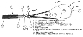
図1Aに示す一つの実施の形態においては、装置10は、好適な形状及び寸法を有する外科的な無菌保護装置またはブリッジ20を備え、冠状静脈洞内へ経血管カテーテルを介したその導入を許容する。図示するように、ブリッジ20は、上面22と、下面24と、2つの平坦で丸い近傍及び遠方端28、29に向かって平坦化する2つのアーチ状の側面26とを備える全体的にアーチ状のボディである固体を備え、ボディ20の2つの端28、29は、略同一面上で延伸し、近傍コアワイヤ/プッシュワイヤ30の遠方端32及び遠方コアワイヤ/プッシュワイヤ40の近傍端42に対して長手方向に位置合わせされる。これらの構成要素は、ブリッジ20及びコアワイヤ30、40上で伸びるニットまたは織物ポリエステルまたは他の好適な材料から形成された延伸さや50に順に収容される。例示する実施の形態では、縫合ラップ60は、コア/プッシュワイヤ30、40に対してさや50を保持するために適用され、装置10の様々な構成要素の物理的な位置決めを維持する。別の実施の形態では、収縮可能な管部分または縫合ラップ材料60を、コアワイヤを保持するために、ブリッジ20及び各コアワイヤ30、40の接合部分上に適用可能である。
In one embodiment shown in FIG. 1A, the
コアワイヤ30及び40は、単に、保護要素20の一方の端に当接するか、あるいは保護要素20の端の上部もしくは底部上に配置されてよいが、図示する実施の形態においては、例えば、はんだ付け、溶接あるいは他の好適な取付手法で、主に、溝28a、29aあるいは平坦化された端28,29に取り付けられる短いハイポチューブ長さを用いることができる。別の実施の形態においては、長手方向のぎざぎざあるいは溝28a、29aは、コアワイヤの端32、42を受ける寸法及び形状で、保護要素20の各平坦化された端28、29に形成可能である。
The
図1Cに示すように、近傍コアワイヤ30の遠方端32に対応するスロット28a/短いハイポチューブ長さは、遠方コアワイヤ40の近傍端42に対応するスロット29a/短いハイポチューブ長さよりも長く、ブリッジ20の各平坦化された端28、29は、それに対応してより長い。つまり、ブリッジ20の平坦化された近傍領域28は、ブリッジの遠方領域29より顕著に長い。対応してより長い溝28aを備えるブリッジの近傍領域を延伸することで、コアワイヤ30とのより長いオーバーラップが得られ、従って安定性が増す。一方、遠方端29は、LCxが典型的には中隔壁に非常に接近しているので、埋め込まれた際に中隔壁との接触を低減するように比較的短い。
As shown in FIG. 1C, the slot 28a / short hypotube length corresponding to the far end 32 of the
使用において、以下に更に詳細に説明するように、心臓内における最終位置へと保護要素20を進めつつ、最初に遠方コアワイヤ40が血脈構造を介して送り込まれる。具体的には、近傍コアワイヤ30は、ブリッジ20を効果的に「押す」とともに、遠方ワイヤ40は、ブリッジ20を効果的に「引く」。構成要素20、30、40の全体的なアセンブリは、連続的な外さや50によって、一体のユニットとして所定位置に保持される。コアワイヤ端部32、42は、縫合ラップ60によってさや50及びワイヤ30、40に加えられる圧縮によって、ブリッジ20に対して所定位置に保持される。保護ブリッジ20が配置されると、構造上各コアワイヤ30、40からさや50を分離するようにさや50からコアワイヤ30、40が引き出されて一方の端で各コアワイヤ、他方の端でさや50に張力が加わり、これによって保護要素20がさやによってカバーされてその後ろに残される。ブリッジ20は、さや50にぴったりとフィットし、一方の他方に対する相対的な移動を生じにくくする。さや材料50の一方の端は、次に、引っ張られて僧帽弁環を再形成し、ロックされ、余剰のさや50は切断され、これは後述して詳細に説明する。縫合ラップ60は、例えば、Teleflex社から市販されている、TEVDEK(登録商標)5-0USP(例えば、~0.004インチの厚さ)PTFE含浸編組ポリエステル繊維非吸収性外科的縫合糸である。縫合ラップ60は、コアワイヤ30、40を除去した後にインプラント10に残り、さや及びコアワイヤに沿って近傍並びに遠方で延伸するとともに、さや50、コアワイヤ30.40及びブリッジ20の接続部に適用され得る。
In use, the
保護要素20は、好ましくは、0.020インチ×0.070インチのニチノールワイヤ等の放射線不透過性の巻回ワイヤから形成されるが、同様あるいは異なる寸法の他の材料を用いてもよいことは明らかである。形状記憶材料から形成することで、ブリッジ20が、維管束系を介した導入に適するように(例えば、線形構成に向かって)変形することを許容できる。しかしながら、形状記憶材料は、好ましくは、装置が展開された後、図に示すようにアーチ状の構成に戻る。
The
部材20は、直径、あるいは高さ及び幅が略0.010インチから略0.080インチの間の円形断面あるいは矩形断面を有してよく、それらの値の間で0.001インチのインクリメントを適宜行ってよい。図示するように、保護要素20の端は、進んでいる際に、冠状静脈洞の壁に外傷をもたらさないように好ましくは丸みを帯びている。保護装置20は、好ましくは、下部にある冠状動脈(例えば、LCx)上の近傍に延伸するのに十分な半径を有するアーチ形状あるいは半球形状を有し、張力要素から下部にある動脈への圧縮力の伝達を防止する。圧縮力は、代わりに、保護装置上及び当該保護装置に沿って分散され、心筋かん流を害する圧縮から動脈を保護する。保護要素の端部分28、29は、効果的に「足」を形成し、これは、冠状動脈をまたぎつつ冠状静脈洞の壁にもたれかかることが可能であり、保護装置20が左の回旋動脈状の所定位置に保持され、コアワイヤ30、40が除去された後の張力下で、さや50によって加えられる圧縮力が分担及び分散される。
The
図1Aの実施の形態は、その基部から例えば略0.4インチから略0.7インチの直線距離をまたぐ中央アーチを有し、それらの値の間において0.01インチのインクリメントを適宜行ってよい。図示する中央アーチは、例えば、略0.10インチから略0.20インチの高さhを有し、それらの値の間において0.01インチのインクリメントを適宜行ってよい。 The embodiment of FIG. 1A has a central arch spanning a linear distance of, for example, approximately 0.4 inches to approximately 0.7 inches from its base, with 0.01 inch increments between those values as appropriate. good. The illustrated central arch has, for example, a height h of approximately 0.10 inches to approximately 0.20 inches, with an appropriate increment of 0.01 inches between those values.
図1C~1Eから分かるように、中空テザー/さや材料50及びブリッジ20は、完全に埋め込まれ、一方でコアワイヤ30,40は除去される。図1Hに示すように、コアワイヤ30、40は、好ましくは、ステンレススチール合金から形成され、PTFE等の潤滑材料がコーティングされ、ブリッジ20から取り外した後の身体からの除去を容易にする。コアワイヤは、直径が、例えば、略0.010から略0.020インチの間、あるいはそれらの値の間で0.001インチのインクリメントが任意で行われる。さや/テザー50は、中空の編組材料から形成される。本開示では、さや材料50を「テザー」あるいは「縫合糸」とも称する。
As can be seen from FIGS. 1C-1E, the hollow tether /
一つの実施の形態において、図1Rに示すように、さや50は、DSM、DyneemaまたはTeleflex社から市販される、1-2mmの超高分子量ポリエチレン(「UHMWP」)コアレスラウンド編組から形成可能である。好ましくは、テザー/さや50は、放射線不透過性を増加させるため、重量で少なくとも20%のビスマスを担持する。追加あるいは代替的には、タングステン、タンタル及び硫酸バリウム等の追加あるいは代替的な放射線不透性物質をさや材料に含ませることができる。これらの材料は、例えば、織物等の編組に包含された引き出し金属(例えば、白金、あるいは他の放射線不透性物質)ワイヤとして、あるいはテザー内に画定された中央の経路に沿って引き出しワイヤを案内することで包含することができる。更なる実施の形態においては、超高分子量ポリエチレンは、クリープ抵抗の改善のためのテザー材料として用いることができ、好ましくは、1-2mmの寸法であり、Teleflex社から市販品を利用可能である。テザー/さや50について編組材料を示したが、他の好適な材料も使用可能な点、明らかである。
In one embodiment, as shown in FIG. 1R, the
図1F及び1Gは、それぞれ、ガイドワイヤから遠方コアワイヤ40の遠方端への移行領域を提供するクリンプ70の外側面図及び断面図である。もし備えられる場合、インプラントの近傍端の第2のクリンプは、さや50の近傍端を、近傍コアワイヤ30の近傍端へ取り付けるための代替あるいは追加的な構造取付位置を提供可能である。図1I~1Mに、ひだ及びその使用態様について更に図示する。図示するように、クリンプ70は、外部近傍テーパ略円錐面72と、外部遠方略円錐面74と、2つの中間テーパ外部円錐面とを備える。クリンプの遠方端は、直径がクリンプ70の近傍端より小さく、さや50内に収容された遠方コアワイヤ40の近傍端44を受けるための比較的大きな近傍穴76と、ガイドワイヤ1400の近傍端1402を受ける寸法の比較的幅狭な交差遠方穴78とを画定する。クリンプ70は、好ましくはインプラント10のコアワイヤ40に当初から取り付けられる変形可能な金属材料から形成される。ガイドワイヤを導入し、適切に心臓を経由して身体(以下に更に詳細に説明する)の外に送り出た後、インプラント10のクリンプ70は、ガイドワイヤに(例えば、ハンドクリンパ)クリンプされ、コアワイヤ30、40と、保護要素20と、縫合ラップ60を有するさや50とを備えるインプラント10は、保護要素がLCx動脈にまたがるまで、脈管構造を通って送り込まれる。
1F and 1G are outside views and cross-sectional views of the
図1Nは、保護要素220、あるいは「ランディングゾーン」を形成する顕著に延伸された近傍部分228を有するアーチ、あるいは冠状静脈洞内にインプラントされた際に堅固で安定した構造、を有するインプラント210の更なる実施の形態を示す。このランディングゾーンは、次に、経カテーテル環状形成処置が完了した後、置換弁をインプラントするためのロケーションとして機能する。具体的には、延伸近傍部分228によって形成されたランディングゾーンにとって提供される心臓内の比較的堅固な表面を有することで、自然の組織への当該置換弁の固定が容易になる。もし備えられる場合、近傍部分228は、従って、例えば3~80mmの間の任意の好適な長さを有することができ、それらの値の間において1mmのインクリメントを適宜行ってよい。もし備えられる場合、遠方部分229は、0.5mmと約10mmの間の任意の好適な長さを有することができ、それらの間の値において0.5mmのインクリメントを適宜行ってよい。
FIG. 1N shows an implant 210 having a
図1Oは、開示のインプラント(例えば10、210)において使用され得る保護装置あるいはブリッジ320の第3の実施の形態を示す。ブリッジ320は、近傍及び遠方スロット328a、329aを、ブリッジ320の近傍及び遠方端328、329に有し、その内部に溶接されたハイポチューブ長さを収容することで、ひいてはコアワイヤ30、40を収容し、位置決め及び安定性を向上させる。ハイポチューブ区間を備えたスロットよりも、代わりに、放電加工(「EDM」)技術でブリッジ20の各端に穴を形成することもできる。
FIG. 1O shows a third embodiment of a protective device or bridge 320 that may be used in the disclosed implants (
図1Pは、ブリッジ420の近傍及び遠方領域428、429から外側に延伸する近傍及び遠方延伸部分428b、429bを備える保護ブリッジ420を備えるインプラント410の更に別の実施の形態を示す。近傍延伸部分428bは、近傍コアワイヤ430の遠方端スリーブ432bによって順に受けられ、同様に、近傍延伸部分429bは、遠方コアワイヤ440の近傍端スリーブ442bによって受けられる。コアワイヤ430、440は、患者の脈管構造に沿って送り込まれた際に、さや及び保護ブリッジ420を押すこと及び引っ張ることを容易にするため設けられる。好ましくは、コアワイヤ430、440は、潤滑性、かつ疎水性あるいは親水性の材料、例えば、PTFEまたはPVPによって被覆される。延伸部分428b、429bは、任意の好適な長さであるが、ある実施の形態においては、延伸部分は、インストールされた際に、インプラント410の環の範囲の5、10、15、20、25、30、35または40パーセントを横断するのに十分な長さを有し、それらの値の間において1パーセントのインクリメントを適宜行ってよい。別の実装態様においては、もし備えられる場合、延伸部分428b、429bは、例えば、3~100mmの間の任意の好適な長さを有し、それらの値の間において1mmのインクリメントを適宜行ってよい。当該実施の形態において、延伸部分428b、429bは、図1Qに示すようにインプラントのロック部分のスリーブ部分とオーバーラップするのに十分な長さを有してよい。ロック及びスリーブについて、図14~20に関連して以下に更に詳細に説明する。
FIG. 1P shows yet another embodiment of an implant 410 comprising a
図1S及び1Tは、本開示に係る保護ブリッジの第5の実施の形態の態様を示し、他方、図1U及び1Vは、本開示に係る保護ブリッジの第6の実施の形態の態様を示す。これらの実施の形態は、いくつかの様態において前記の実施の形態と異なる。例えば、全体的なインプラント構造は、好ましくは、管状さや材料50(特に図示せず)に包含されるが、追加の、好ましくは放射線不透過性のテザーが、保護要素を通って及び/または保護要素の周囲に織られたインプラントの長さに沿って設けられる。図示するように、この追加のテザーは、保護要素によって画定される開口を経由して送られる。図示するように、保護ブリッジの第5及び第6の実施の形態は、それぞれ、各ブリッジの近傍及び遠方領域から外側に延伸する近傍及び遠方延伸部分を備える。第5の実施の形態は、その端が比較的幅広な足を有し、ブリッジを着座させるためにより安定したプラットフォームを提供し他方、第6の実施の形態は、各端に設けられたテーパ状の足を有し、インプラントの長さに沿って保護ブリッジの近傍及び遠方から剛性がよりなだらかに変化する。保護要素を経由して送られた内側のテザーは、好ましくは、その全長に沿って放射線不透性であり、これは、テザーの内部に長さに沿って放射線不透過性材料を全長に設けること、あるいは、テザー自体の織物内に放射線不透性物質を包含させることで得られる。 1S and 1T show aspects of the fifth embodiment of the protection bridge according to the present disclosure, while FIGS. 1U and 1V show aspects of the sixth embodiment of the protection bridge according to the present disclosure. These embodiments differ from the embodiments described above in some ways. For example, the overall implant structure is preferably encapsulated in tubular sheath material 50 (not specifically shown), but additional, preferably radiopermeable tethers, pass through and / or protect the protective element. It is provided along the length of the implant woven around the element. As shown, this additional tether is sent through an opening defined by a protective element. As shown, the fifth and sixth embodiments of the protective bridges include near and far extension portions that extend outward from the near and far regions of each bridge, respectively. A fifth embodiment has relatively wide legs at its ends and provides a more stable platform for seating the bridge, while a sixth embodiment is tapered at each end. It has a foot and the stiffness changes more gently from near and far from the protective bridge along the length of the implant. The inner tether sent via the protective element is preferably radiation impermeable along its entire length, which provides a radiation impermeable material along its length inside the tether. This, or by including a radiation impermeable substance in the fabric of the tether itself.
図1Wに示すように、第5の実施の形態に関し、保護要素の側面図が提供され、等角図が図1AKで提供され、(好ましくは放射線不透過性の)テザーは、組み立ての際に保護要素の穴を経由して通される。図示するように、テザーは、アーチの上及び保護要素の着座部分/端の下に通される。保護要素及びテザーの更なる側面図である図1Xに示すように、必要に応じて、熱収縮性材料のチューブ、織物糸または管状の布材料等のカバーが、テザー及び保護要素の組み合わせの上に適用される。図示する例では、熱収縮性PTFEのチューブが構造に適用され、それによって、テザー及び保護要素の相対的な位置が保持される。図1Yは、保護要素のアーチの上部を通るテザーを示す、図1Wのアセンブリの上面図であり、一方で図1Zは、インプラントの着座部分/端の下を通るテザーを示す。 As shown in FIG. 1W, for a fifth embodiment, a side view of the protective element is provided, an isometric view is provided in FIG. 1AK, and a (preferably radiation opaque) tether is provided during assembly. Passed through the holes in the protective element. As shown, the tether is passed over the arch and below the seated portion / end of the protective element. As shown in FIG. 1X, which is a further side view of the protective element and tether, a cover, such as a tube of heat shrinkable material, a woven yarn or a tubular fabric material, is optionally over the combination of the tether and the protective element. Applies to. In the illustrated example, a tube of heat-shrinkable PTFE is applied to the structure, thereby preserving the relative positions of the tether and protective elements. FIG. 1Y is a top view of the assembly of FIG. 1W showing the tether passing over the top of the arch of the protective element, while FIG. 1Z shows the tether passing under the seated portion / end of the implant.
図1AAに示すように、第6の実施の形態に関し、保護要素の側面図を提供し、等角図が図1ALで提供され、テザーは、組み立ての際に保護要素の穴を経由して通される。図示するように、テザーは、アーチの上及び保護要素の着座部分/端の下に通される。保護要素及びテザーの更なる側面図である図1ABに示すように、必要に応じて、熱収縮性材料のチューブ、織物糸または管状の布材料等のカバーが、テザー及び保護要素の組み合わせの上に適用される。図示する例では、熱収縮性PTFEチューブが構造に適用され、それによって、テザー及び保護要素の相対的な位置が保持される。図1ACは、保護要素のアーチの上部を通るテザーを示す、図1AAのアセンブリの上面図であり、一方で図1ADは、インプラントの着座部分/端の下を通るテザーを示す。 As shown in FIG. 1AA, for the sixth embodiment, a side view of the protective element is provided, an isometric view is provided in FIG. 1AL, and the tether is passed through the hole in the protective element during assembly. Will be done. As shown, the tether is passed over the arch and below the seated portion / end of the protective element. As shown in FIG. 1AB, which is a further side view of the protective element and the tether, a cover, such as a tube of heat shrinkable material, a woven yarn or a tubular fabric material, is optionally over the combination of the tether and the protective element. Applies to. In the illustrated example, a heat-shrinkable PTFE tube is applied to the structure, thereby preserving the relative positions of the tether and protective elements. FIG. 1AC is a top view of the assembly of FIG. 1AA showing the tether passing over the top of the arch of the protective element, while FIG. 1AD shows the tether passing under the seated portion / end of the implant.
図1AE~AGは、それぞれ、インプラントに包含される引っ張り軽減キャップの等角、背面及び正面図である。引っ張り軽減部は、その長さに沿って少なくとも部分的に(好ましくは全体的に)テザー及び保護ブリッジの周囲を包囲する内部チャンネルを有し、このチャンネルは、インプラントの足/着座領域を収容するための比較的大きなチャンネルを備える比較的幅広な後部分有しており、この後部分は、さや材料を包囲するよう構成及び適用された比較的幅狭な前部分に向かってテーパ状になっている。図1AHは、保護要素に対する引っ張り軽減部の配置を示す。図1AI及び1AJは、それぞれ、保護要素、テザー及び熱収縮性チューブの組み合わせ構造上に配置された引っ張り軽減部の上面及び側面図である。引っ張り軽減部は、熱収縮性材料から形成可能、及び/または、接合剤等によって所定位置に保持されることが可能である。また、引っ張り軽減部は、編組チューブ材料、織物ポリマーあるいは金属ワイヤ、あるいは、柔軟なデュロメータのモールドポリマー材料であってよく、引っ張り軽減部のテーパ構造は、デュロメータに、その長さに沿った勾配を与え、引っ張りを軽減する機能を達成する上での一助となる。引っ張り軽減部は、保護要素からさやまでインプラントの長さに沿って剛性に勾配を与え、引っ張り軽減部がない場合に生じる結合及び応力の集中を回避する一助となる。図1AMは、引っ張り軽減部を備えないインプラントの等角図である。 1AE-AG are equiangular, back and front views of the tension reduction cap included in the implant, respectively. The tension relief has an internal channel that surrounds the tether and protective bridge at least partially (preferably entirely) along its length, which accommodates the implant's foot / seating area. It has a relatively wide rear part with a relatively large channel for, which taper towards a relatively narrow front part configured and applied to surround the pod material. There is. FIG. 1AH shows the arrangement of the pull reducing portion with respect to the protective element. 1AI and 1AJ are top and side views of a pull-reducing portion arranged on a combined structure of a protective element, a tether and a heat shrinkable tube, respectively. The pull-reducing portion can be formed from a heat-shrinkable material and / or can be held in place by a joining agent or the like. Further, the tension reduction portion may be a braided tube material, a woven polymer or a metal wire, or a flexible durometer molded polymer material, and the taper structure of the tension reduction portion gives the durometer a gradient along its length. Helps to achieve the function of giving and reducing pulling. The tension relief provides a gradient in stiffness along the length of the implant from the protective element to the pod, helping to avoid the bond and stress concentration that would occur in the absence of the tension relief. FIG. 1AM is an isometric view of an implant without a pull-reducing portion.
好ましくは、内部のテザーは、その全長に渡って放射線不透過性であり、取り付けの際にその視認性を向上させる。図1ANは、放射線不透過性(例えば、白金)ワイヤが内部に挿入され、放射線不透過性を向上させた状態の、テザー、この場合は編組テザーを示す分離図である。従って、図示する白金ワイヤの存在によって放射線不透過性が向上されるとともに、ワイヤあるいはフィラメントは、タングステン担持ポリマー、タンタル担持ポリマーから形成されてよい、及び/または、ビスマス、タングステン、タンタル、硫酸バリウムおよびその他等の1つ以上が、一つまたは別の手法(例えば、ポリマーあるいは織物材料への包含)で含浸された編組縫合糸材料を用いてもよい。 Preferably, the internal tether is radiation opaque over its entire length, improving its visibility during installation. FIG. 1AN is a separation diagram showing a tether, in this case a braided tether, in a state where a radiation opaque (for example, platinum) wire is inserted inside to improve the radiation opacity. Thus, the presence of the illustrated platinum wire enhances radiation impermeable, and the wire or filament may be formed from a tungsten-supported polymer, tantalum-supported polymer, and / or bismuth, tungsten, tantalum, barium sulfate and / or. A braided suture material may be used in which one or more of the others and the like are impregnated with one or another technique (eg, inclusion in a polymer or woven material).
図1AQは、放射線不透過性ワイヤが内側テザーの内側にテザーの長さに沿って通された状態の、第5の実施の形態の保護ブリッジ(第6の実施の形態に係るテーパ状の保護ブリッジも同様に適用可能)及びそれを経由して通されたテザーの組み合わせ構造の上面図である。 FIG. 1AQ shows the protection bridge of the fifth embodiment (tapered protection according to the sixth embodiment) in which the radiodensity wire is passed through the inside of the inner tether along the length of the tether. A bridge is also applicable) and is a top view of the combined structure of the tether passed through it.
図1APの概要図は、上記の要素を含み、保護ブリッジの端上に配置されるあるいは当接される、取り外し可能なプッシュチューブ及び取り外し可能なプルチューブの相対位置を追加で示す。プッシュ及びプルチューブは、先行する実施の形態に係るコアワイヤ(例えば、430、440)と同様の機能を発揮し得る。インプラントの他の全ての構成要素と同様に、プッシュ及びプルチューブも、先行する実施の形態と同様にさや50(特に図示せず)に包囲される。取り外し可能なプッシュ/プルチューブは、各側で連続的な内側のテザー上で組み立てられ、保護ブリッジから置換クリンプ(開示の別の部分で説明)へ延伸し、締結インプラントに対するガイドワイヤの交換の一助となる。プッシュ及びプルチューブは、好適には、PEEK、HDPE等のポリマー材料から形成可能である。開示されるように、インプラントが配置されると、プッシュ及びプルチューブは、コアワイヤ(例えば、430、440)と同様に、引き抜くことで除去される。図1AQは、図1AO及び1APと同一の構成要素を示すが、保護ブリッジの一方の端の引っ張り軽減部の相対的な配置を更に示す。インプラントは、好ましくは、本明細書で開示するように、引っ張り軽減部の下のさや及び保護要素の上に配置されるチューブ状要素を更に備え、更に、全体構造の上に配置されたさや50を備える。好ましくは放射線不透過性である内側さやは、外側さや50より直径が小さい。編組材料から形成される内側さやを図示するが、ポリマーワイヤ、金属ワイヤ等の他の材料を使用してもよい。
The schematic of FIG. 1AP additionally shows the relative positions of the removable push tube and the removable pull tube that include the above elements and are placed or abutted on the end of the protective bridge. The push and pull tubes can perform the same function as the core wire (eg, 430, 440) according to the preceding embodiment. Like all other components of the implant, push and pull tubes are also surrounded by a pod 50 (not shown) as in previous embodiments. Detachable push / pull tubes are assembled on a continuous inner tether on each side and extend from the protective bridge to the replacement crimp (discussed elsewhere in the disclosure) to help replace the guidewire to the fastening implant. Will be. The push and pull tubes can preferably be formed from polymer materials such as PEEK, HDPE and the like. As disclosed, once the implant is placed, the push and pull tubes are removed by pulling out, as well as the core wire (eg, 430, 440). FIG. 1AQ shows the same components as FIGS. 1AO and 1AP, but further shows the relative placement of the pull mitigation section at one end of the protection bridge. The implant preferably further comprises a tubular element placed on the pod under the tension relief and a protective element, as disclosed herein, and a
図2は、僧帽弁締結環状形成処置において、保護装置20を用いたインプラント10の使用を概略的に示す。図2は、冠状動脈回旋枝552上の冠状静脈洞550の一部を通って延伸する張力要素(好ましい実施の形態においては、編組縫合材料)として用いたさや材料50を示す。図2は、冠状動脈552上に保護要素20が延伸した状態で、冠状静脈洞550内に位置するインプラント10、及びが冠状動脈552の一方の側に位置する近傍及び遠方部分28、29を示す。インプラント10のテザー部分50に張力が配置されるので、近傍及び遠方部分28、29は、冠状動脈552の一方の側の位置に保持され、圧縮力を、下部にある冠状動脈(LCx)552の代わりに冠状静脈洞550の壁に伝達する。
FIG. 2 schematically illustrates the use of the
図3A、3B、3C及び3Dは、締結環状形成保護装置10の機能の代替的な図である。
3A, 3B, 3C and 3D are alternative views of the function of the fastening ring forming
図3Aは、左冠状動脈554の回旋枝552上に延伸する冠状静脈洞550と共に、心臓の外部生体構造を示す。図3Bは、冠状動脈552と冠状静脈洞550とのオーバーラップ関係を示す拡大図である。図3Cは、締結環状形成の間に張力下で配置される、下部にある冠状動脈552を圧縮しており、心筋かん流と干渉している、中空テザー50を示す。図3Dは、冠状動脈552への圧縮力の付与を防止している保護装置20を通って延伸し、従って残り、心筋組織を通常通りにかん流させる中空テザー50を示す。
FIG. 3A shows the external biological structure of the heart, along with the
ブリッジ/保護装置(例えば、20、220、320、420)については、中空テザー材料50を、下部にある冠状動脈(例えばLCx)から離間させて支持する様々な形状及び構成を想定することができる。保護装置/ブリッジ20は、予め望ましい構成に形成される、あるいは、脈管構造に沿って送り込まれる際には全体的に線形であり、完全に展開されると望ましい保護装置の形状となる記憶合金材料から形成可能である。ブリッジ20は、望ましい場合、3次元曲線を有し、個人の個別の生体構造に適合する。
For bridge / protection devices (
III.経皮的僧帽弁締結環状形成
A.僧帽弁逆流
僧帽弁あるいは三尖弁の逆流(リーク)は、様々な異なる原因、例えば、虚血性心疾患、心筋梗塞、後天性あるいは先天性の心筋症、先天的欠陥、外傷、感染症及び様々な形態の心臓疾患によって生じ得る。原発性心筋疾患は、膨張による弁膜逆流を引き起こし、弁環の拡大をもたらし、乳頭筋組織の伸し過ぎ、変性、あるいは破裂によって、あるいは、乳頭筋の機能不全もしくは位置異常によって弁小葉の接合異常をもたらし得る。この逆流は、心房細動等の心臓リズム異常を引き起こし、それ自体が心筋機能における避けられない劣化をもたらす。当該劣化は、機能障害、うっ血性心不全及び顕著な痛み、苦痛、生活の質の減少あるいは若死等にさえ関連する。
III. Percutaneous mitral valve fastening ring formation A. Mitral valve regurgitation Mitral or tricuspid regurgitation (leak) has a variety of different causes, such as ischemic heart disease, myocardial infarction, acquired or congenital myocardial disease, congenital defects, trauma, infections. And can be caused by various forms of heart disease. Primary cardiomyopathy causes valvular regurgitation due to swelling, resulting in valvular enlargement, overstretching, degeneration, or rupture of the papillary muscle tissue, or dysfunction or misalignment of the papillary muscles resulting in valvular lobular junction abnormalities. Can bring. This regurgitation causes cardiac rhythm abnormalities such as atrial fibrillation, which in itself results in inevitable deterioration in myocardial function. The deterioration is associated with dysfunction, congestive heart failure and marked pain, distress, reduced quality of life or even premature death.
経皮的な環状形成等の、危険性が低く、侵襲性を最小にした処置は、より多くの患者に弁逆流の機械的な治療を受けることを可能にする。 Low-risk, minimally invasive procedures, such as percutaneous ring formation, allow more patients to receive mechanical treatment for regurgitation.
B.経皮的締結環形状
外科手術の危険性及び複雑さが(心臓切開手術と比較して)低減されるので、カテーテルベースの心臓弁処置は、患者のより広い人口に好適である。例えば、経皮的な締結環状形成(欠陥がある心臓弁の輪あるいは環の再構築あるいは補強)によって弁小葉を再度並べることで、ダメージを受けたあるいは機能不全をおこした心臓弁を修復するために用いることが可能なカテーテルベースの弁修復のための改善された装置及び方法を本明細書に開示する。ある例においては、経皮的な締結環状形成は、円周あるいは放射状の張力装置を送り出すために用いられる。これらの処置の例については、WO2004/045378及びUS2005/0216039号公開公報に詳細に開示されており、参照として、任意の目的のためにその全体を本明細書に組み込む。
B. Percutaneous Fastened Ring Shape A catheter-based heart valve procedure is suitable for a larger population of patients because it reduces the risk and complexity of surgery (compared to cardiotomy). For example, to repair a damaged or dysfunctional heart valve by rearranging the valve lobules by percutaneous fastening ring formation (reconstruction or reinforcement of a defective heart valve ring or ring). Disclosed herein are improved devices and methods for catheter-based valve repair that can be used in. In one example, percutaneous fastening ring formation is used to deliver a circumferential or radial tensioning device. Examples of these procedures are disclosed in detail in WO2004 / 045378 and US2005 / 0216039 Publications, which are incorporated herein by reference in their entirety for any purpose.
一般に、環状形成処置を行なうために用いられる装置は、冠状静脈(動脈)洞へ導入される、事前に形成された経頸静脈バルーン先端ガイドカテーテル等のガイドカテーテル(GC)を備え得る。逆行性の冠状放射性静脈造影図は、大心臓静脈及び中隔穿通枝静脈を加圧して視覚化する。冠状動脈再疎通のために設計された高性能ガイドワイヤは、例えば、大心臓静脈へ、その後、基部の中隔穿通枝静脈へと屈折可能なマイクロカテーテルを用いて導かれ得る。 In general, the device used to perform the annulus formation procedure may include a guide catheter (GC), such as a preformed transjugular balloon tip guide catheter, that is introduced into the coronary sinus. Retrograde coronary radiovenography is visualized by pressurizing the great cardiac vein and the septal perforator vein. High-performance guidewires designed for coronary recanalization can be guided, for example, to the great cardiac vein and then to the septal perforator vein at the base using a refractable microcatheter.
一般に、環状形成処置は、更に、治療対象の、内部身体組織、器官、構造、内腔及び空間を撮像する画像システムを使用することを含んでよい。例えば、核磁気共鳴映像法(MRI)等の画像システムを用いたアクティブ装置ナビゲーションを容易にするために、送信機あるいは受信機コイルを用いることができる。この撮像は、一般に、X線技術、X線透視法、MRI、電磁陽電子ナビゲーション、映像技術(例えば、内視鏡検査、関節鏡検査等)、超音波及び他の同様の技術に基づく様々な撮像方法を用いて、任意のあるいは所定の平面に沿って行うことができる。ある実施の形態においては、リアルタイムMRI(rtMRI)、心臓内超音波、あるいは電磁誘導が採用される。締結環状形成において特に有用な補助となりえるものは、XFMであり、これは、例えば心筋の構造を対象としてMRIとともにX線が用いられ、心臓の構造を介したその軌道において環状形成ワイヤをガイドする一助となる。XFM技術については、デ・シルバらによるCirculation114:2342-2350(2006)に開示されている。ガイドカテーテルは、対象の身体、例えば、腕、首あるいは脚静脈を介して心腔等の心臓への経皮的なアクセス等の経皮的なアクセスを可能にする。ある実施の形態においては、ガイドカテーテルは、心臓の心室及び/または心房へのアクセス用に設計される。ガイドカテーテルは、例えば、弁操作カテーテルあるいはマイクロカテーテルあるいは疎通ニードルカテーテルを含む1つ以上の第2のカテーテルの導入を許容する。第2のカテーテル(または複数のカテーテル)は、心臓、心臓内の特定の構造等の対象の身体内の対象となる器官、組織あるいは構造を治療、影響を与える、あるいは操作するために用いられる。ガイドカテーテルが心臓への経皮的な(あるいは他の)アクセスに用いられる場合、ガイドカテーテルは、止血を維持しつつ、心臓へ弁操作カテーテル等の1つ以上の第2のカテーテルの導入を許容する。第2のカテーテルは、互いに共軸あるいは隣接してよく、あるいは、身体の外部の複数のアクセス点から導入され得る。 In general, the annulus formation procedure may further include the use of an imaging system that images the internal body tissue, organs, structures, lumens and spaces of the subject to be treated. For example, transmitter or receiver coils can be used to facilitate active device navigation using imaging systems such as magnetic resonance imaging (MRI). This imaging is generally based on various imaging techniques based on X-ray techniques, X-ray fluoroscopy, MRI, electromagnetic positron navigation, imaging techniques (eg endoscopy, arthroscopy, etc.), ultrasound and other similar techniques. The method can be used along any or predetermined plane. In certain embodiments, real-time MRI (rtMRI), intracardiac ultrasound, or electromagnetic induction is employed. A particularly useful aid in fastening ring formation is the XFM, which uses X-rays with MRI, for example, targeting the structure of the myocardium and guides the ring formation wire in its orbit through the structure of the heart. It helps. The XFM technique is disclosed in Circulation 114: 2342-2350 (2006) by De Silva et al. Guided catheters allow percutaneous access, such as percutaneous access to the heart, such as the heart chambers, via the subject's body, eg, arm, neck or leg veins. In certain embodiments, the guide catheter is designed for access to the ventricles and / or atria of the heart. The guide catheter allows the introduction of one or more second catheters, including, for example, a valve-operated catheter or a microcatheter or a communication needle catheter. A second catheter (or plurality of catheters) is used to treat, influence, or manipulate a target organ, tissue, or structure within the body of a subject, such as the heart, a particular structure within the heart. When the guide catheter is used for percutaneous (or other) access to the heart, the guide catheter allows the introduction of one or more second catheters, such as valve-operated catheters into the heart, while maintaining hemostasis. do. The second catheter may be coaxially or adjacent to each other, or may be introduced from multiple access points outside the body.
ガイドカテーテルは、僧帽弁修復方法の好適な構成要素に適するために異なる形状で利用可能である。例えば、ガイドカテーテル形状は、異なる曲率半径を有する異なる冠状動脈洞に適するか、異なる冠状静脈、経大動脈ならびに経中隔アクセス経路に適するか、あるいは異なる内径の心房及び心室に適するよう供される。それら全ての形状は、好適な第一、第二、第三の曲線で適合可能である。経皮的かつ経血管的な僧帽弁環状形成を実行するのに好適なカテーテル構成の例は、従来知られており、米国特許出願公開公報第2005/0216039号に開示されており、任意の目的のためにその全体を参照として本明細書に組み込む。 Guide catheters are available in different shapes to suit the preferred components of the mitral valve repair method. For example, the guide catheter shape is provided to suit different coronary sinuses with different radii of curvature, different coronary veins, transaortas and transseptal access pathways, or different inner diameters of the atria and ventricles. All of them are compatible with suitable first, second and third curves. Examples of catheter configurations suitable for performing percutaneous and transvascular mitral valve annulus formation are conventionally known and disclosed in US Patent Application Publication No. 2005/0216039, which are optional. Incorporated herein by reference in its entirety for purposes.
冠状静脈洞への任意の利用可能なアプローチを用いてもよいが、例えば、頚静脈を介した静脈アプローチが好ましい。更に別の実施例として、ガイドカテーテルは、大腿部あるいは頚静脈等の静脈内へ導入され、下あるいは上大静脈を通って、心臓の右心室内にガイドされる。図4A及び図4Bに、締結環状形成のための軌道の2つの例を示す。第1の軌道(「シンプル」あるいは「RV」軌道としてラベル付けされる)では、環状形成ワイヤが上大静脈を介して右心房に入り、次に、冠動脈口を通って冠状静脈洞へ導入される。ワイヤは、大心臓静脈を通って、基部の中隔穿通枝静脈等の基部の血管内に送り込まれる。次に、ワイヤは、心臓間質を通って中隔穿通枝静脈を出て、右心室に入り、中隔三尖弁交連(前尖と中隔尖の交差点)に沿って右心房に再び入る。 Any available approach to the coronary sinus may be used, but for example, a venous approach via the jugular vein is preferred. As yet another embodiment, the guide catheter is introduced into a vein such as the thigh or jugular vein and guided through the inferior or superior vena cava into the right ventricle of the heart. 4A and 4B show two examples of trajectories for forming a fastening ring. In the first orbit (labeled as a "simple" or "RV" orbit), a ring-forming wire enters the right atrium via the superior vena cava and is then introduced through the coronary ostium into the coronary sinus. Ru. The wire is fed through the great cardiac vein into the basal blood vessel, such as the basal perforator vein. The wire then exits the septal perforator vein through the heart stroma, enters the right ventricle, and reenters the right atrium along the septal tricuspid valve commissure (the intersection of the anterior and septal apex). ..
ガイドワイヤは、次に、例えば、脈管スネアを用いて退避される。ガイドワイヤの遠方端を捕らえ、身体の外部にまで露出するまで脈管構造を通って退避させる任意の好適な器具を使用可能である。図3E~3Yに、ガイドワイヤの退避を容易にする例示的な、好適かつ改善されたスネアシステムを示す。 The guide wire is then retracted using, for example, a vascular snare. Any suitable instrument can be used that captures the far end of the guide wire and retracts it through the vasculature until exposed to the outside of the body. 3E-3Y show an exemplary, suitable and improved snare system that facilitates retracting the guide wire.
図3Eに示すように、スネアカテーテル1300は、その長さに沿って内部に中間管状部材1320をスライド可能に受ける延伸外側管状部材あるいはさや1310によって画定されて提供される。次に、中間管状部材1320は、その長さに沿って内部にスライド可能に配置されたハイポチューブ等の更なる延伸内側管状部材1330を備える。管状部材1320及び1330の相対的な軸方向変位は、編組スネアバスケット1340を膨張あるいは収縮させる。スネアバスケット1340は、編組面によって画定され、中間管状部材の遠方端1324に取り付けられる近傍端1342と、内側管状部材1330の遠方端1334に取りへ付けられた遠方端1344とを備える。そのため、管状部材1320に対して管状部材1330を離間するようにスライドさせることにより、端1324及び1334が互いに引き離されると、バスケット1340の編組フィラメントが延伸して放射状かつ内側につぶれ、次に、外側管状部材あるいはさや1310に対してバスケット1340が近傍に引っ張られることを許容する。内側管状部材1330は、好ましくは、ステンレススチールまたはニッケルチタン合金ハイポチューブ等の金属部材であり、ガイドワイヤをそこに通すことが可能な、その長さに沿った更なる内腔を画定する。好ましくは、内側管状部材1330の遠方端1334及びスネアバスケット1340の遠方端部分1344上に非外傷性円錐テーパ状非外傷性遠方先端1350が形成される。先端1350は、これらの構成要素の上にモールドすることができ、あるいは、事前に形成されて、紫外線活性接着剤等でシステムに接着されてもよい。好ましくは、先端1350は、遠方開口を画定し、ガイドワイヤが内側管部材1330の内部で画定された内腔を通過した後に当該開口を通過することを許容する。先端1350は、PEBAXポリマー、35Dナイロン材料あるいは他の好適な非外傷性の材料等のポリマー材料、あるいは他の材料から形成され、潤滑性、かつ疎水性あるいは親水性の被覆(例えば、PVP)を備えてよい。非外傷性の材料によって先端1350を画定することで、スネアカテーテル1300が、急カーブを含む屈折した脈管構造を通ることを容易にして、肺動脈弁近傍の右心室内に到達し、冠状静脈洞の壁を通過した後に中隔の壁を通過するガイドワイヤを途中で捕える、あるいは、対象となる中隔穿通と右心室流出路(RVOT)との間にガイドワイヤを通す。内側管状部材1330は、先端1350の略全長を横断してもよいが、好ましくは、端の遠方端の手前で止まり、脈管構造を通過する際に端が屈曲できるようにする。
As shown in FIG. 3E, the
好ましくは、管状部材1310、1320及び1330の遠方端部分1314、1324、1334上に、マーカーバンド1316、1326及び1336をそれぞれ形成する。また、望ましい場合、肺動脈弁の近傍の右心室の領域内の中隔の壁を通過したガイドワイヤの遠方端の捕捉を容易にする2あるいは3次元のループ形状を有する内側ターゲットフィラメントまたはワイヤ1360が設けられてもよい。ワイヤ1360は、中間管状部材の遠方端1324に取り付けられる近傍端1362と、内側管状部材1330の遠方端1334に取り付けられる遠方端1364とを備える。ターゲットワイヤ1360は、更にその内部に、1つ以上の平面に置かれた1つ以上のワイヤループ1366を画定する。管状部材1320、1330の相対的な長手方向移動の遠方端を長手方向に変位することでバスケット1340を延伸させる場合、ターゲットワイヤ1360が同様に延伸され、ループ1366がつぶれる。
Preferably,
図3Iは2つの異なるターゲットワイヤ1360を示し、左側のものは、2つのループを有し、右側のものは、単一のループを有する。いずれの場合でも、ワイヤ1360は、本質的に単一の平面上にある。一方、図3Jの実施の形態は、2つのワイヤを有し、それぞれが、互いに略90度で配置された平面において置かれる2ペアのループを備える。ターゲット1360の目的は、ガイドワイヤがバスケット1340のフィラメント間を通過する際に、その内部でより強固にガイドワイヤを捕えることである。具体的には、ターゲットワイヤのループは、冠状静脈洞から中隔を通過した後に左心室に入るガイドワイヤを捕えることの一助となり、バスケット1340の及びワイヤループ1366の延伸並びにつぶれることは、スネアカテーテル1300の捕捉効率を向上させ、その内部の捕捉したガイドワイヤ1340とともにバスケットの、外側管状部材1310の遠方端1314近傍への退避を容易にする。図3Kは、ワイヤのバリエーションを示し、3つのループ状うねり1368が、ループ1366に倣うように設けられ、単一のフィラメントを用いて、1つ以上の平面において形成される。図示するように、うねりのうちの2つが、同一面上にあり、他の2つのうねりの平面に対して略90度オフセットされた第2の平面上にある第3のうねり1368によって分離される。ワイヤ1360は、ニチノールあるいは他の材料等の様々な材料から形成され、複数のマーカーバンド1369(図3K)を備えてよい。一つの実施の形態においては、ワイヤ1360は、Fort Wayne Metal社から市販されているDFTワイヤ等の複合ワイヤから形成される。
FIG. 3I shows two
図3Lは、内側フィラメント1360がない、展開可能なメッシュバスケット1340を備えるスネアカテーテルの遠方領域を示す。図3Mは、当該バスケットを示すが、単一ループフィラメント1360を備える。DFTワイヤを使用する場合、バスケット1340の材料がそうでなくても、典型的には放射線不透過性で視認性がある。図3Nは、図3Jで示すように2つのダブルループワイヤを備えるバスケットを示し、ダブルループのセットは、異なる平面において置かれる。図3Oは、一つのワイヤループが、2つのフィラメントのそれぞれに設けられる類似アレンジメントを示し、各ループが異なる平面に置かれる。図3Pは、図3Kのワイヤ1360内に含まれるメッシュバスケット1340を示す。
FIG. 3L shows a distant region of a snare catheter with a
図3Q~3Uは、図示するスネアカテーテル1300を用いる例示的な方法を示す。図3Qは、例えば、右心室の領域で完全に展開したスネアカテーテルを示す。ガイドワイヤ1400は、スネアカテーテルのメッシュバスケット1340と、同様にそこに配置されたワイヤ1360のうねり1368とを通過している。ワイヤ1360上のマーカーバンド1369は、視認性を向上させる。図3Rは、メッシュバスケット1340の伸展する軸延伸及び半径方向寸法におけるその同時の減少を示す。図3S~Uは、バスケット1340及び中間管状部材1320の、外側管状部材あるいはさやの遠方端1314への近接退避を示す。バスケット1340の延伸は、また、ワイヤのうねり1368をまっすぐにし、ガイドワイヤ1400をもつれさせる。引っかかったガイドワイヤがさや1310内に引っ張られることで、捕捉される。その後、ガイドワイヤがアクセス可能となるまで、例えば患者の外部へ引き出すことで、患者からスネアカテーテル1300を近接退避させることができる。
3Q-3U show exemplary methods using the illustrated
図3V~3Yは、蛍光透視法において得られた静止画像を介した実際の使用におけるスネアカテーテル1300を示す。図3Vは、冠状静脈洞へと送り出されたガイドカテーテル1500を示し、ガイドワイヤ1400の遠方端が、スネアカテーテル1300の編組バスケット1340によって捕えられるように、中隔壁を通過している。図3Wは、構成要素の相対的配置をより明確に示す拡大図である。図3Xは、さや1310へ近接退避されたつぶれたバスケット1340を示し、それによってガイドワイヤ1400が捕えられて把持される。図3Yは、ガイドカテーテル1500と同様に退避されたガイドワイヤの遠方端を示し、例えば後述するクリンプ70によって、インプラントがガイドワイヤ1400の近傍端にクリンプされた後、ガイドワイヤ1400が、締結インプラント(例えば10)によって後に占められる経路に続く所定位置に保持される。
3V-3Y show the
ガイドワイヤを捕え、患者からその遠方端を除去した後、クリンプ(例えば、70)を介してガイドワイヤの近傍端上にインプラントをクリンプすることで、インプラント(例えば、10)がガイドワイヤと交換される。次に、保護装置あるいはブリッジ(例えば、20)の遠方端(例えば、29)が中隔壁に近接し、ブリッジがLCx動脈を横断するまで、患者からガイドワイヤを退避させると、ガイドワイヤの経路に沿ってインプラント(例えば、10)が送り込まれる。例えば、放射性血管造影により、危険にさらされた冠状動脈の位置を確認する。代替的なアプローチでは、冠状静脈は、画像ガイダンスで右心房あるいは右心室から反対方向において冠状静脈洞の枝へと入る。 The implant (eg, 10) is replaced with a guidewire by capturing the guidewire, removing its distant end from the patient, and then crimping the implant over the near end of the guidewire via a crimp (eg, 70). The wire. The guidewire is then retracted from the patient until the distant end (eg, 29) of the protective device or bridge (eg, 20) is close to the medial septum and the bridge crosses the LCx artery into the guidewire path. An implant (eg, 10) is delivered along. For example, radioangiography confirms the location of endangered coronary arteries. In an alternative approach, the coronary vein enters the branch of the coronary sinus in the opposite direction from the right atrium or right ventricle with imaging guidance.
図4A及び4Bに示す代替あるいは「複雑な」右心房締結軌道は、更に、基部の中隔心筋を介して冠状静脈洞の近傍の右心房内へと後方に延伸する。ワイヤは、後方向に移動して、中隔の深部組織を横断し、冠状静脈洞の開口から出る。冠状静脈洞が僧帽弁環状形成から離間していても、環状形成が独自に適切に残るように、冠状静脈洞及びその平面560に関連する結果として得られた締結環状形成の平面を図4Cに示す。図が示すように、締結平面560は、冠状静脈洞が僧帽弁環から幾何学的に離間していても僧帽弁接合を増強し、これは、左心室流出路に対して「傾斜」しているからである。従って、締結平面560と僧帽弁環562の平面との間の図示する角度αは、有用である。また、締結環状形成の図示する軌道は、心室収縮期の間に、僧帽弁接合及び左室流出路のリラクゼーションの往復を生じさせる。
The alternative or "complex" right atrium fastening orbit shown in FIGS. 4A and 4B further extends posteriorly through the base septal myocardium into the right atrium near the coronary sinus. The wire travels posteriorly, traverses the deep tissue of the septum and exits through the opening of the coronary sinus. The resulting plane of the fastening ring formation associated with the coronary sinus and its
ガイドワイヤは、ガイドカテーテルとともに作用するための寸法を有し、通常、ガイドカテーテルよりも長い。例えば、長さ約100~250センチメートル及び直径約0.1~2mmのガイドワイヤを、上記のガイドカテーテルとともに使用することができる。第2のカテーテル、例えば、張力デリバリーカテーテル等、がガイドカテーテルとともに用いられる場合、当該第2のカテーテルもまた、ガイドカテーテルとともに作用するための寸法を有し、通常、ガイドカテーテルよりも長い。 The guide wire has dimensions to work with the guide catheter and is usually longer than the guide catheter. For example, a guide wire with a length of about 100-250 cm and a diameter of about 0.1-2 mm can be used with the guide catheter described above. When a second catheter, such as a tension delivery catheter, is used with a guide catheter, the second catheter also has dimensions to work with the guide catheter and is usually longer than the guide catheter.
ガイドカテーテルは、曲げあるいはねじりの際に加わる力等の外力によりつぶれることに抗するのに好適な強度及び柔軟性の両方を提供する任意の好適な材料あるいは材料の組み合わせから形成することができる。当該材料の例は、これらに限定されないが、ポリエチレンまたはポリウレタン等のポリマー、カーボンファイバー、セラミック、あるいは、ニチノール、白金、チタン、タンタル、タングステン、ステンレススチール、銅、金、コバルトクロム合金あるいはニッケル等の金属である。ガイドカテーテルは、任意に、金属ファイバー、カーボンファイバー、ガラス、ファイバーグラス、リジッドポリマーあるいは他の高強度材料から形成あるいは強化される。特定の実施の形態においては、ガイドカテーテル材料は、MRI互換性があり、例えば、編組ニチノール、白金、タングステン、金、またはカーボンファイバーから形成される。また、ガイドカテーテルの外表面は、テフロン(登録商標)等の疎水性材料または物質、あるいは、ガイドカテーテルの対象の身体への挿入の一助となる、及び/または、ガイドカテーテルの対象の身体内での移動の一助となる親水性材料(例えば、PVP)等の他の潤滑性材料で被覆されてよい。 Guide catheters can be formed from any suitable material or combination of materials that provides both suitable strength and flexibility to resist crushing by external forces such as forces applied during bending or twisting. Examples of such materials include, but are not limited to, polymers such as polyethylene or polyurethane, carbon fibers, ceramics, or nitinol, platinum, titanium, tantalum, tungsten, stainless steel, copper, gold, cobalt-chromium alloys or nickel. It is metal. The guide catheter is optionally formed or reinforced from metal fiber, carbon fiber, glass, fiberglass, rigid polymer or other high strength material. In certain embodiments, the guide catheter material is MRI compatible and is formed from, for example, braided nitinol, platinum, tungsten, gold, or carbon fiber. Also, the outer surface of the guide catheter aids in the insertion of a hydrophobic material or substance such as Teflon®, or the guide catheter into the body of the subject, and / or within the body of the guide catheter subject. It may be coated with another lubricating material such as a hydrophilic material (eg, PVP) that aids in the movement of the material.
また、ガイドカテーテルは、屈折可能な先端、例えば、単一の軸自由度を有する単純な屈折可能な先端を備えることができる。例示的な(非限定的な)固定支点及び移動可能支点屈折先端を有するカテーテルは、市販されており、例えば、米国特許番号第5397321、第5487757、第5944689、5928191、6074351、6198974及び6346099号に屈折可能な先端を有するカテーテルが開示されており、これらの全体を任意の目的のために参照として本明細書に組み込む。従って、任意の好適な固定支点あるいは移動可能支点屈折先端を有するカテーテルを、本開示のガイドカテーテルとして適用可能である。ガイドカテーテルは、また、その長手軸に対するカテーテルの回転の一助となる構造あるいは機構を含んでよい。 The guide catheter can also include a refractable tip, eg, a simple refractable tip with a single degree of freedom of axis. Catheter with exemplary (non-limiting) fixed fulcrum and movable fulcrum refraction tips are commercially available, eg, US Pat. Catheter with a refractable tip is disclosed, all of which are incorporated herein by reference for any purpose. Therefore, a catheter having any suitable fixed fulcrum or movable fulcrum refraction tip can be applied as the guide catheter of the present disclosure. The guide catheter may also include a structure or mechanism that aids in the rotation of the catheter with respect to its longitudinal axis.
ガイドカテーテルは、ガイドカラーと、ハンドグリップと、ハンドルと、他のガイドカテーテルの動作の一助となる近傍端の構成あるいは装置とを備えてよい。ガイドカテーテルには、電気的、工学的、あるいは機械的な制御機構を含む様々な制御機構を、ガイドカラーを介して取り付けることができる。例えば、ガイドワイヤは、機械式の制御機構に含まれる。ガイドカラーは、追加の動作上の特徴、例えば、ガイドカテーテルの手動制御の一助となるグリップ、ガイドカテーテル内腔あるいは細分された内腔の配列を示すマーカー、ガイドカテーテルの送り込み深さを示すマーカー、ガイドカテーテルの動作あるいは対象の生理学的な信号を計測する器具(例えば、温度計または圧力モニター)、または、ガイドカテーテル内腔に結合されて少量かつ正確な量の注入液を注入する注入制御機構等を備えることができる。ある実施の形態においては、ガイドカラーは、ガイドカテーテル内で金属の編組物に電気的に結合された器具を備え、それによってガイドカテーテルを同時にMRIにおける受信コイルとして使用することを可能とする。 The guide catheter may include a guide collar, a handgrip, a handle, and a near-end configuration or device that aids in the operation of other guide catheters. Various control mechanisms, including electrical, engineering, or mechanical control mechanisms, can be attached to the guide catheter via the guide collar. For example, the guide wire is included in a mechanical control mechanism. The guide collar is an additional operational feature, such as a grip that aids in manual control of the guide catheter, a marker that indicates the alignment of the guide catheter lumen or subdivided lumen, a marker that indicates the depth of delivery of the guide catheter, and the like. An instrument that measures the movement of the guide catheter or the physiological signal of the subject (eg, a thermometer or pressure monitor), or an infusion control mechanism that is coupled to the lumen of the guide catheter to inject a small and accurate amount of infusion solution, etc. Can be provided. In certain embodiments, the guide collar comprises an instrument electrically coupled to a metal braid within the guide catheter, which allows the guide catheter to be simultaneously used as a receiving coil in an MRI.
ガイドカテーテルを対象の身体へと及び身体内をガイドするためシステムとともに用いられるガイドワイヤは、ガイドカテーテルに関連して先に説明した材料を含む任意の好適な材料あるいは材料の組み合わせから形成されてよい。例示的な(非限定的な)ガイドワイヤは、金属のより糸(例えば、外科手術用ステンレススチール、ニチノール、白金、チタン、タングステン、銅あるいはニッケル)、カーボンファイバー、あるいは編組ナイロン等のポリマー等の、装置とともに用いるのに好適な強度及び柔軟性を有する材料から形成される。特定の(非限定的な)ガイドワイヤは、ニチノールのより糸あるいは他の柔軟かつ抗よじれ性の材料から形成される。ガイドカテーテルあるいはガイドワイヤは、その遠方端に隣接して、放射線不透過性マーカー(例えば、ガイドワイヤの外周の周囲の白金またはタンタルのバンド)等の画像処理特徴、構造、材料あるいは装置を備えることができる。別の例として、ガイドワイヤは、エッチングまたは切り欠きを備える、あるいは、ソノリフレクティブな材料で覆われており、血管内、心臓内、経食道、または他の超音波画像方法によって得られる画像を向上する。別の例として、ガイドワイヤは、T1-短縮あるいはT2-短縮剤によって覆われ、MRIを用いた受動的な視覚化を容易にする。さらに別の例として、光ファイバーの第2カテーテルを、ガイドカテーテルの第2のカテーテル内腔へ及び内腔を通して挿入してよく、遠方ガイドワイヤ内腔穴を通ってガイドワイヤを展開する際の、対象内のガイドワイヤの位置を視覚化する上での一助となる。ある実施の形態においては、ガイドワイヤ及び/またはガイドカテーテルは、その遠方先端に、心筋骨格、筋肉あるいは結合組織等の組織を貫通する上で一助となる構成、器具あるいは装置を備える。例えば、ガイドワイヤの遠方先端は、組織を穿刺するために一点に向かって鋭利になっている、あるいは、その遠方先端にコアリング構造また鉗子を有する第2のカテーテルを、ガイドカテーテルとともに用いることができる。代替的な実施の形態においては、ガイドワイヤは、組織の横断の一助となる高周波あるいはレーザ切断エネルギーを伝達することができる。しかしながら、代替的な実施の形態においては、ガイドワイヤの遠方端は、折り曲げられてJ形状あるいはピグテール形状の端を提供し、操作の際にガイドワイヤによる組織の挿通を防止している。更に別の代替的な実施の形態においては、ガイドワイヤは、それ自体が屈折可能な先端を有し、自然の組織平面に無関係に組織の横断を容易とする。1つ以上の第2のカテーテルは、ガイドカテーテルの内腔内に展開することができる。ガイドカテーテルのように、各第2のカテーテルは、近傍端と遠方端とを有するが、全ての第2のカテーテルが内腔を有するわけではない。例えば、無内腔の第2のカテーテルは、温度プローブ、高周波あるいは低温アブレーションプローブ等の様々なプローブ、あるいは、固体の針を備えてよい。 The guide wire used with the system to guide the guide catheter to and within the body of the subject may be formed from any suitable material or combination of materials, including the materials described above in connection with the guide catheter. .. Exemplary (non-limiting) guide wires are metal strands (eg, surgical stainless steel, nitinol, platinum, titanium, tungsten, copper or nickel), carbon fiber, or polymers such as braided nylon. Formed from a material with strength and flexibility suitable for use with the device. Certain (non-limiting) guide wires are formed from nitinol twine or other flexible and anti-kinking material. The guide catheter or guide wire is adjacent to its distant end and is provided with image processing features, structures, materials or devices such as radiopaque markers (eg, platinum or tantalum bands around the perimeter of the guide wire). Can be done. As another example, the guidewire has an etching or notch or is covered with a sonoreflective material to improve the image obtained by intravascular, intracardiac, transesophageal, or other ultrasound imaging methods. do. As another example, the guidewire is covered with a T1-shortening or T2-shortening agent, facilitating passive visualization using MRI. As yet another example, a second catheter of optical fiber may be inserted into and through the lumen of the second catheter of the guide catheter, subject to deployment of the guidewire through the distant guidewire lumen. Helps to visualize the position of the guide wire inside. In certain embodiments, the guidewire and / or guide catheter is provided at its distant tip with a configuration, instrument or device that aids in penetrating tissues such as myocardial skeleton, muscle or connective tissue. For example, the distant tip of the guide wire may be sharpened towards a point to puncture the tissue, or a second catheter with a coring structure or forceps at the distant tip may be used with the guide catheter. can. In an alternative embodiment, the guide wire can transfer high frequency or laser cutting energy to help traverse the tissue. However, in an alternative embodiment, the far end of the guide wire is bent to provide a J-shaped or pigtail-shaped end to prevent tissue penetration by the guide wire during operation. In yet another alternative embodiment, the guidewire has a refractable tip in itself, facilitating crossing of the tissue regardless of the natural tissue plane. One or more second catheters can be deployed within the lumen of the guide catheter. Like guide catheters, each second catheter has a near-end and a distant end, but not all second catheters have a lumen. For example, the non-luminal second catheter may include a temperature probe, various probes such as a high frequency or low temperature ablation probe, or a solid needle.
例示的なかつ非限定的な第2のカテーテルは、疎通ニードルカテーテルであり、ガイドカテーテルを通って及び心腔内で展開可能であり、僧帽弁の周囲に冠状静脈洞を介して締結環状形成結紮糸を配置する。疎通ニードルカテーテルは、第2のカテーテルの一種で、対象となる身体の組織、器官あるいは構造に縫合糸を適用するために用いることができる。 An exemplary and non-limiting second catheter is a circulatory needle catheter that can be deployed through a guide catheter and intracardiac and concludes via a coronary sinus around the mitral valve. Place the thread. The communication needle catheter is a type of second catheter that can be used to apply sutures to the tissue, organ or structure of the body of interest.
C.張力付与
さや材料50を介して、環状形成締結によって張力が加えられ、このさやは、好ましくは、上記のように中空の編組縫合糸材料である。張力は、以下に詳細に説明するロックデリバリーカテーテルと共同して、血管アクセス点において外面化した際に、さや50の両端に加えられてよく、ロックデリバリーカテーテルは、当該カテーテルの端にマウントされたロックを介して縫合糸の両端を案内する。張力は、僧帽弁環の円周の縮小を所望の程度まで達成するか、あるいは、僧帽弁逆流が低減されるか、あるいは、僧帽弁流入閉塞のような他の有害な症状の除去を達成するまで、ロックデリバリーカテーテルの遠方端でロックを介してテザーの画像誘導によって加えることができる。次に、さや50内の張力は、2013年11月7日になされた継続中の米国特許出願第14/074517号に開示されるロックデリバリーカテーテル、あるいは、図14~20を参照して本明細書で以下に説明するロックデリバリーカテーテルのロックの固定によって保持される。代替的に、結び目がガイドカテーテルを介して結ばれて押されてもよい。ロックあるいは結び目は、望ましくは、2つの締結軌道が交差する右心房あるいは右心室、または、血管アクセス点、あるいはそれら2つの間に配置することができる。従って、望ましい場合、例えば、デリバリーカテーテルを介して適用される固定装置に対する反対圧力によって、張力を伝達することができる。固定の前に、張力は解放あるいは低減されてよく、例えば、保護装置の位置を変える、あるいは僧帽弁環の円周の縮小レベルを下げることを達成する。
C. Tension is applied by an annular formation fastening through the
張力が加えられることで、好ましくは、弁逆流が繰り返しかつ非侵略的に好適な画像技術によって評価される。当該画像技術は、左心房または肺静脈または肺動脈等である影響を受けた室内における、X線血管造影、電磁気位置検出、MRI、外部または腔内または血管内超音波、X線コンピュータ断層撮影、圧力変換器、あるいは、上記の「融合」または組み合わせを含む。弁逆流が低減(あるいは除去)され、望ましい張力が達成された後、上記のロックあるいは結び目デリバリーシステムを用いて張力を固定し、任意の望ましい手法でロックあるいは結び目近傍の超過さや材料がカット及び除去される。本開示の1つの様態に係る切断器具を、図21~22を参照して以下に更に説明するように用いることができる。 By applying tension, valve regurgitation is preferably evaluated by a repetitive and non-invasively suitable imaging technique. The imaging technique is X-ray angiography, electromagnetic position detection, MRI, external or intraluminal or intravascular ultrasound, radiographic computer tomography, pressure in an affected room, such as the left atrium or pulmonary vein or pulmonary artery. Includes converters, or "fusions" or combinations described above. After valve regurgitation is reduced (or removed) and the desired tension is achieved, the tension is fixed using the lock or knot delivery system described above and any excess or material near the lock or knot is cut and removed in any desired manner. Will be done. Cutting instruments according to one aspect of the present disclosure can be used as further described below with reference to FIGS. 21-22.
閉ループを形成するために結果として生じる周辺のさや50が結ばれる場合、さや50は、基本的に締結縫合糸となる。それ以上の詳細はなしで、当業者は、本開示を利用して、この発見を最大限に活用できる点、理解され得るところである。
If the surrounding
締結環状形成技術において用いる、保護装置(例えば20)を備えたインプラントの使用を開示した。しかしながら、開示のインプラントは、下部にある冠状動脈と交差する領域における冠状静脈洞を介して部分的であっても延伸する他の環状形成装置とともに用いることができる。例えば、保護装置(例えば、20)は、米国特許第7090695号の冠状静脈洞装置、あるいは米国特許出願第10/787574号(米国特許公開公報第2004/0254600号)の膨張式冠状静脈洞装置等の任意の冠状静脈洞環状形成装置を用いた冠動脈の圧縮から保護するために用いることができる。それらの装置は、血管内のデリバリーのために設計されているが、本明細書に開示の保護装置は、カテーテルベースのアプローチの代わりに開胸外科的修復を用いて埋め込まれる環状形成装置とともに用いることができる。これらの装置によっても冠状動脈圧縮の問題は生じ、この問題を回避するために本明細書に開示する保護装置を用いてよい。従って、本開示の実施の形態は、締結環状形成とともに用いる保護装置に限定されず、また、カテーテルベースのデリバリー技術とともに用いる装置に限定されない。 Disclosed is the use of implants with protective devices (eg 20) for use in fastening ring forming techniques. However, the disclosed implants can be used with other annulus-forming devices that extend even partially through the coronary sinus in the area intersecting the lower coronary arteries. For example, the protective device (for example, 20) may be a coronary sinus device of US Pat. No. 7,090695, an inflatable coronary sinus device of US Patent Application No. 10/787574 (US Patent Publication No. 2004/0254600), or the like. Can be used to protect against compression of the coronary arteries using any of the coronary sinus ring forming devices. Although these devices are designed for intravascular delivery, the protective devices disclosed herein are used in conjunction with a ring-forming device that is implanted using open surgical repair instead of a catheter-based approach. be able to. These devices also cause the problem of coronary artery compression, and the protective devices disclosed herein may be used to avoid this problem. Accordingly, embodiments of the present disclosure are not limited to protective devices used with fastening ring formation, nor are they limited to devices used with catheter-based delivery techniques.
任意の種類の冠状静脈洞環状形成インプラントとともに用いられた場合、保護装置(例えば、20)は、インプラント(例えば、10)の一体的な部分として、あるいは、インプラントと保護すべき下部にある冠状動脈との間の配置に好適な個別の装置として提供される。インプラントの一体部分として提供される場合、インプラントは、サポートのアーチが下部にある冠状動脈の上で延伸するように冠状静脈洞に配置される。代替的な実施の形態においては、保護装置は、保護すべき冠状動脈の上に位置するまで、カテーテルシステムを介して送り込まれる個別の装置として提供される。 When used with any type of coronary sinus annulus implant, the protective device (eg, 20) is an integral part of the implant (eg, 10), or the underlying coronary artery to be protected with the implant. It is provided as a separate device suitable for placement between and. When provided as an integral part of the implant, the implant is placed in the coronary sinus so that the arch of the support extends over the underlying coronary artery. In an alternative embodiment, the protective device is provided as a separate device that is delivered via a catheter system until it is located above the coronary artery to be protected.
僧帽弁締結環状形成装置は、本明細書に開示するように、心臓組織を放射状内側に押し、本来の僧帽弁領域の近傍の心臓内へ突出する保持構造を形成し、人工経カテーテル僧帽弁(TMV)の移植及び固定を可能にする。ここで使用するように、人工僧帽弁、経カテーテル僧帽弁、TMV、人工僧帽弁装置、人工僧帽弁インプラント等の用語は、本来の僧帽弁領域内または当該領域に隣接して埋め込み可能な任意の人工装置を含み、この人工装置は、弁部材(例えば、フレーム、ステント、リング、ファスナ、テザー、弁装置の一部)を備えない装置とともに、弁装置を含む。ある実施の形態においては、締結環状形成は、固定されるTMVのための内部リッジ、(上記の)ランディングゾーン、固定平面等(主に、「保持構造」と称する)を形成可能である。 The mitral valve fastening ring-forming device, as disclosed herein, pushes the heart tissue radially inward to form a retention structure that projects into the heart near the original mitral valve region and is an artificial transcatheter monk. Allows transplantation and fixation of the mitral valve (TMV). As used herein, terms such as artificial mitral valve, transcatheter mitral valve, TMV, artificial mitral valve device, artificial mitral valve implant, etc. are used within or adjacent to the original mitral valve region. Includes any implantable man-made device, which includes a valve device as well as a device without a valve member (eg, frame, stent, ring, fastener, tether, part of the valve device). In certain embodiments, the fastening ring formation is capable of forming an internal ridge for the TMV to be fixed, a landing zone (above), a fixed plane, etc. (predominantly referred to as a "holding structure").
心臓内で保持構造に固定されたTMVは、例えば、経カテーテル、経血管伝達アプローチで、放射状に圧縮した状態で心臓に送り出される放射状に圧縮可能かつ放射状に膨張可能な人工装置を備える。一旦心臓に入ると、TMVは、加えられた膨張力(例えば膨張式のバルーン)またはデリバリーの際に加えられる圧縮力を除去することでTMVを自己膨張させる固有の自己膨張材料(例えばニチノール)を用いて膨張する。膨張することで、TMVは、僧帽弁締結環状形成装置によって形成された保持構造に固定され、心臓内でTMVが位置ずれすることを防止する。例えば、TMVは、保持構造の両側で膨張及び/または保持構造上にクランプされる管状フレームを備えることができる。 The TMV, immobilized in a retention structure within the heart, comprises, for example, a transcatheter, a transvascular transduction approach, a radially compressable and radially inflatable man-made device that is delivered to the heart in a radially compressed state. Once in the heart, the TMV has a unique self-expanding material (eg, nitinol) that self-expands the TMV by removing the applied inflating force (eg, inflatable balloon) or the compressive force applied during delivery. Inflate using. By inflating, the TMV is anchored to the retention structure formed by the mitral valve fastening annulus forming device and prevents the TMV from being misaligned within the heart. For example, the TMV can include a tubular frame that expands and / or is clamped onto the holding structure on both sides of the holding structure.
膨張すると、埋め込まれたTMVは、心臓組織に対して半径方向外側に力を加えることができる。この半径方向外側の力は、望ましくないが心臓組織内の血管を圧縮し、狭窄及び血流低下を引き起こす。同時に、僧帽弁締結環状形成装置によって加えられた半径方向内側の力は、また、望ましくないが外部から心臓組織内の血管を圧縮し得る。この2重の心臓血管の圧縮は、虚血、心臓発作及び他の合併症のリスクを悪化させる。特別に考慮すべきは、大心臓静脈の近傍の冠状動脈回旋枝及びその合流枝であり、これらは、埋め込まれたTMVと周囲の僧帽弁締結環状形成装置との間に位置することができる。従って、本明細書で開示する保護装置は、(僧帽弁締結環状形成装置を介して)外側から内側、及び(TMVを介して)内側から外側の両方の圧縮から当該血管を保護する一助となる。 Upon expansion, the implanted TMV can exert a radial lateral force on the heart tissue. This radial lateral force, undesirably, compresses blood vessels in the heart tissue, causing stenosis and diminished blood flow. At the same time, the radial medial force applied by the mitral valve fastening ring-forming device can also undesirably compress blood vessels in the heart tissue from the outside. This double cardiovascular compression exacerbates the risk of ischemia, heart attack and other complications. Of particular consideration are the coronary circumflex branches near the great cardiac vein and their confluences, which can be located between the implanted TMV and the surrounding mitral valve fastening ring-forming device. .. Accordingly, the protective device disclosed herein aids in protecting the vessel from both lateral to medial (via the mitral valve fastening ring forming device) and medial to lateral compression (via TMV). Become.
図6は、心臓の僧帽弁領域の概略断面図であり、心臓の壁602内に配置された埋め込まれたTMV612と、心臓の壁の周囲に配置された締結環状形成装置610とを備える例示的なインプラントシステム600を示す。装置610は、冠状動脈652の上に渡されたアーチ状の保護装置620を備え、動脈を、装置610によって外側から、及びTMV612によって心臓の壁602の内側に加えられる外方向の膨張力614の両方による圧縮から保護する。例示的な保護装置620は、2つの平らな、全体的に共面の近傍及び遠方部分628、629間で延伸するアーチ状の部分を備える。ブリッジまたは保護装置620は、他の例示的な保護装置に関して本明細書で開示した特徴及び寸法の任意の組み合わせを有してよい。
FIG. 6 is a schematic cross-sectional view of the mitral valve region of the heart, comprising an implantable TMV612 disposed within the wall of the
図7は、本開示の保護装置を備えない、冠状静脈洞750を介して、僧帽弁の周辺を部分的に延伸する張力縫合糸(例えば、50)を示す。従って、冠状動脈回旋枝752は、冠状静脈と動脈とがオーバーラップする、張力縫合糸下で捕捉され、望まれない圧縮を動脈に加える。TMVが僧帽弁内に埋め込まれる場合、動脈752に内側から外側への追加の圧縮力が加わる。保護装置なしでは、動脈752はつぶれる、及び/または、抗力によってつままれる。
FIG. 7 shows a tension suture (eg, 50) that partially stretches around the mitral valve through the
図8は、本開示の僧帽弁締結環状形成装置810及び埋め込まれた際の例示的なTMV812のおおよその位置を示す。図示するように、保護装置820は、(少なくとも部分的に)動脈852の上をわたり、外側の張力部材及び心臓壁802の内側のTMVの両方からの圧縮から保護する。図8は、動脈852の半径方向厚さの約半分のみを超えて延伸する寸法のアーチ部分を備える保護装置820の使用を示し、動脈を部分的に圧縮にさらす。図8に示す配置では、張力部材及びTMVによる抗力によって動脈852の半径方向内側半分を圧縮し、動脈が部分的に圧縮される。他の実施の形態においては、アーチの半径方向高さは大きく(例えば、動脈の最大半径方向直径と同じ大きさ)、動脈852の半径方向厚さの大部分、または全てを収容し、これによって図8に示すものと比較して、より大きい程度で(例えば、完全に、または略完全に)動脈を保護する。例えば、アーチの高さは、少なくとも3.5mmである。僧帽弁締結環状形成装置によって心臓内に形成された保持構造は、外科技術あるいは経カテーテル技術を用いて、環あるいは環上僧帽弁環状形成リングあるいはバンドとは異なる平面に配置できる。
FIG. 8 shows the approximate location of the mitral valve fastening
図5に、不一致の締結及び僧帽弁の環平面の一例を示す。本開示の僧帽弁締結環状形成によって形成された保持構造は、不一致な締結及び環平面のために、部分的に非円周となり得る。しかしながら、図8に示すように、保持構造は、TMVがTMVの望ましくない変位あるいは移動なく保持構造に確実に固定されるように、僧帽弁領域の全円周の略半分以上に延伸することができる。 FIG. 5 shows an example of inconsistent fastening and the ring plane of the mitral valve. The retaining structure formed by the mitral valve fastening ring formation of the present disclosure can be partially non-circumferential due to inconsistent fastening and ring planes. However, as shown in FIG. 8, the holding structure extends to more than about half of the entire circumference of the mitral valve region to ensure that the TMV is secured to the holding structure without unwanted displacement or movement of the TMV. Can be done.
上記のように、捕えられた冠状動脈の「内側から外側へ」の圧縮から保護するように構成された保護装置は、より完全に動脈を保護するために、増加したアーチ高さを有することができる。しかしながら、高さ対高さの割合が増加しない限り、増加した高さは、(保護装置の長さと比較して)比例的に長くなったアーチ長さとなり得る。図9に示すように、これは、保護装置920の近傍及び遠方領域928、929が上に向かって折り曲げられ、保護装置920の中央のアーチ状の領域の底部に応力集中を生させ、心筋を突き、保護装置920の近傍及び遠方領域928、929に沿って均等に分配された圧縮力ではなく、冠状動脈のすぐ隣により集中した圧縮力が働く、という望ましくない結果をもたらす。図10に示すように、保護装置1020の足、近傍及び遠方領域1028、1029の実施の形態は、保護装置1020の主な長手軸に沿った湾曲を備えることができ、心臓の湾曲した壁により合致するようになる。これは、冠状動脈の直ぐ横の心筋に沿ったアーチ状の屈曲への接触点での圧縮集中を防止しつつ、冠状動脈へのより大きな高さを許容する。集中した圧縮は、アーチの防護効果を制限し、心筋に望ましくない圧縮あるいは損傷あるいはびらんを生じさせる。堅固な保護部材のカーブ形成は、締結張力によって加えられた半径方向の力を再分配し、捕捉した冠状動脈のよりよい保護効果が得られる。
As mentioned above, protective devices configured to protect the captive coronary arteries from "inner-to-outer" compression may have increased arch height to protect the arteries more completely. can. However, unless the height-to-height ratio increases, the increased height can be a proportionally longer arch length (compared to the length of the protective device). As shown in FIG. 9, it causes stress concentration at the bottom of the central arched region of the
保護部材のある実施の形態では、非対称のキラリティがあってよい。例えば、保護部材は、その長手軸に沿った螺旋あるいはコルクスクリュー形状を有し、上記の2次元湾曲ではなく、3次元の湾曲を有する。より一般には、保護部材は、少なくともアーチ部分に沿って、3次元あるいは多重平面の湾曲を有することができる。保護部材の非対称のキラリティあるいは多重平面の湾曲は、下部にある冠状動脈に対する締結張力装置の斜めの交差角度問題を解決することが可能である(図11参照)。アーチの上から見ると直線的(図11に示す)な対称的なアーチ形の保護部材1120では、斜めの交差角度がアーチの有効幅を低減し、圧縮から冠状動脈1152を保護するための能力が低下する。
In certain embodiments with protective members, there may be asymmetric chirality. For example, the protective member has a spiral or corkscrew shape along its longitudinal axis and has a three-dimensional curvature instead of the two-dimensional curvature described above. More generally, the protective member can have a three-dimensional or multi-planar curvature at least along the arch. The asymmetric chirality of the protective member or the curvature of the multi-plane can solve the diagonal cross-angle problem of the fastening tensioning device with respect to the underlying coronary arteries (see FIG. 11). In the symmetrical arch-shaped
図12は、例示的なキラル形状の保護部材1220を示し、この保護部材は、冠状動脈1252上にわたるときに横に湾曲し、次に、他の横方向に湾曲し、2つの足1228、1229が略平行に見えるがアーチ(例えば、半径方向内側)の上から見るとオフセットされている。これは、アーチ部分が、図11に示す斜めの角度ではなく、略垂直に冠状動脈1252と交差することを可能にする。図13は、非対称のキラル形状を示す、部分的な立面図からの、別の例示的なキラル形状の保護装置またはブリッジ1320を示す。ブリッジ1320は、動脈の上をわたって湾曲し、左右交互に横方向に湾曲する3次元の湾曲を有することが可能であり、冠状静脈洞に沿って足1328、1329の方向を維持し、僧帽弁に向かって内側に向かいつつ、より短くより効率的な動脈交差を得ることができる。
FIG. 12 shows an exemplary chiral-shaped
図14A及び14Bは、本開示に係るロックデリバリーシステムの態様を示す。限定ではなく説明のために、ロックデリバリーシステム1410は、近傍端及び遠方端を有し、その遠方端にロック1450を備えたデリバリーカテーテルを備える。より具体的には、ロックデリバリーシステム1410は、その内部に内側管状部材1430を有する外側管状部材1420を備える。外側管状部材1420は、管状部材1420、1430の間で画定された環状の空間を洗浄するための洗浄穴を備えた、押さえ止血デリバリー装置ハブ1425に取り付けられた近傍端1422と、ロック1450の外側部分1455のねじ切り部分1457を受けるためにそこに組み込まれた外側内向きねじ切り(メス)ファスナ1427を有する遠方端1424と、を備える。ロック1450の内側部分1452は、内側管状部材1430の遠方端1434に形成されて外部ねじ切りファスナ1439と係合する外側ねじ切り1454を備える。ファスナ1427、1454、1439、1457をねじ切りファスナとして開示するが、任意の好適なファスナを用いることができる。内側管状部材1430は、延伸する外側管状部材1420内でスライド可能である。内側管状部材1430の内部に沿って画定された延伸内腔1435は、インプラント(例えば、10)を介してさや/テザー(例えば、50)を受けるように構成される。ロック1450の内側及び外側部分1452、1455は、開口1455aによって受けられたロック1450の外側部分1455に渡って固定されて横切るように延伸し、ロックの内側部分1452の延伸遠方部分1456内に画定された延伸スロット1458を介して延伸する制限ピン1451に結合される。使用において、ロック1450の内側部分1452に配置された返し1452aは、ロックの外側部分1455の内側通路1459に対してテザー(例えば、50)に引っかかる。テザー/縫合糸/さや1450は、ロック1450の内側部分1452に画定された長手方向開口1452bを経由して送られる。
14A and 14B show aspects of the lock delivery system according to the present disclosure. For illustration purposes, the
内側管状部材1430は、任意の好適な材料、好ましくは、PEEK等のポリマー材料から形成可能である。外側管状部材1420は、好ましくは、編組層を含むポリマー共射出等の編組カテーテル材料として設けられる。ファスナ部分1452と内側管状部材1430との間の螺合接続は、2つの部材を互いに取り付けることを許容し、ロックの遠隔開閉を許容するとともに、ロックが完全に展開された後でも望ましい場合にロックの除去及び退避を許容する。
The
図15A~15Fは、図14のデリバリーシステム1410を用いたデリバリーのための例示のロック1450の態様を示す。図示するように、ロックの内側部分1452は、内側がその中心に沿ってねじ切りされて中央通路を画定する、近傍略環状ボディを備える。この中心通路は、ロックの内側部分1452の延伸する遠方部分1456の一方の側に画定された開口1452aと流体連通し、テザーを通す。延伸スロット1458は、延伸する遠方部分の横方向反対側を横方向に通過し、スロットが略矩形の体積を画定してその横方向に通過するピン1451のスライド係合を許容する。ロックの外側部分1455と内側部分1452との間で可能な相対的な軸方向移動は、ピン1451がスロット1458の一方の端に当接するように構成されるので、スロット1458長さまでに制限される。また、ピン1451及びスロット1458によって提供される結合は、ロック1450の内側1452及び外側1455が互いに回転移動しないようにする。これにより、外側管状部材1420に対する内側管状部材1430の回転によってロック1450の両方部分にトルクが同時に加わることを許容する。
15A-15F show aspects of an exemplary lock 1450 for delivery using the
ロック1450の構成要素は、好ましくは、ステンレススチール等の金属材料から形成される。外側ロック部分1455及び外側管状部材1430を接続する螺合接続は、ロック1450を作動させつつ、ロック1450の所定位置への固定に関する好適な制御を提供する。開口1452aを通って各さや/縫合糸(例えば、50)を送ることで、さや材料が内側管状部材1430の移動に干渉しないようにし、これは、内側ロック部分1452に取り付け及び分離された際の両方の場合に、内側管状部材1430が縫合糸上に乗るので有益である。
The components of the lock 1450 are preferably made of a metallic material such as stainless steel. The threaded connection connecting the
図16A~16Eは、本開示に係るロックデリバリーシステムの更なる態様を示す。図16Aは、1つのペアのスネア縫合糸1470を導入することでロックデリバリーシステム1410を螺合する最初のステップを示し、各縫合糸は、遠方ループ1472を画定し、テザー材料(例えば、50)を当該ループを通して受ける。このステップは、ロックが「開」位置にあり、内側及び外側ロック部分1452、1455が互いに長手方向に離間し、ピン1451がスロット1458の遠方端に存在することで達成される。インプラント(例えば、10)の縫合糸/さや材料(例えば、50)の各端は、各スネア縫合糸1470のそれぞれの遠方ループ1472を通り、インプラント(例えば、10)の心線ワイヤ(例えば、30、40)を除去した後に、図16Bに示すように、内側管状部材1430の内腔を通って近傍に退避される。次に、システム1410の遠方端が、遠方に送り込まれ、インプラント(例えば、10)のテザー(例えば、50)を乗り越え、ロック1450が送られてインプラント(例えば、10)の張力を維持する、例えば僧帽弁を再形成する位置に到達する。図16に示すように、ロックが、心臓内の適切な位置に配置されて張力が加わると、インプラントには、所望の張力が加わるまでテザー/縫合糸を近傍に引くことで、張力が加えられる。次に、内側管状部材1430が外側管状部材1420に対して送り込まれて、ピン1451を、スロット1458内で遠方にスライドさせ、返し1452aによって外側ロック部材1455の中央の穴の内壁に対してテザー/縫合糸を押しつけ、従って張力下でテザー/さや材料が位置に配置される。次に、図16Dに示すように、本実施の形態の場合は、2つの部材間の螺合接続を解除することで、ロック1450の内側部分1452から内側管状部材が分離される。図16Eに示すように、最終ステップは、2つの部材間の螺合接続を分離、好ましくは内側及び外側管状部材を近傍で受動的に引っ張ることで、外側ロック部分1455を外側管状部材1420から解放することであり、これによって現状所定位置に固定されたロック1450との干渉が防止される。
16A-16E show a further aspect of the lock delivery system according to the present disclosure. FIG. 16A shows the first step of screwing the
図17は、引っ張り軽減部分を含む本開示に係るロックの更なる実施の形態を示す。必須ではないが、本明細書に開示する僧帽弁締結処置の特定の状況においては、近傍端においてロック1450の外側部分1455に取り付けられる引っ張り軽減部分1480または保護要素を設けることが有効である。図示する実施の形態においては、ロック1450の外側部分1455は、8字状の外周を有する遠方開口を備え、開口の各半分は、望ましい場合、遠方端に保護ボール1482を備える引っ張り軽減/保護部材1480を受ける寸法を有する。そのため、ロック1450は、保護要素1480なしで、あるいは、1つあるいは2つの当該要素とともに、設けられてよ。保護要素は、冠状静脈洞及び他の組織内でより大きな表面積でさや/テザー材料に加わる張力によって生じた負荷を分散する一助となり、それによって、例えば、締結処置によって生じる組織損傷の機会を減らす。図1P及び1Qを参照すると、一つの実施の形態においては、区間1480及び延伸部428b、429bの長さは、オーバーラップするのに十分長く強健な構造を提供し、例えば、僧帽弁の部分的あるいは完全な置換を容易にするために用いることができる。足1480は、巻かれた金属、プラスチックあるいは複合材料から形成されるが、望ましい場合、柔軟性のあるポリマースリーブで形成することもできる。
FIG. 17 shows a further embodiment of the lock according to the present disclosure, which includes a pull-reducing portion. Although not required, in certain situations of the mitral valve fastening procedure disclosed herein, it may be useful to provide a pull-reducing
図18は、例示的な締結インプラントに接続されたロックデリバリーシステム1410を示す。本実施の形態では、保護ボール1482を備えない保護要素1480を備えるロック1450を示し、コアワイヤ30,40を除去した後、インプラントの縫合糸50が、そこを通る。ロック50と共働するインプラント10は、締結処置が完了した後、僧帽弁上で張力を維持する完全な円周構造を提供する。
FIG. 18 shows a
図19A~19Bは、本開示に係る、本開示の例示的なロックの保護要素あるいは引っ張り軽減部1480の更なる実施の形態を示す。本実施の形態においては、引っ張り軽減部あるいは保護足1480は、更に、伸び縮み可能な遠方スリーブ1484を備え、このスリーブは、各足1484内にスライド可能に収容される。図示するように、各内側伸び縮み可能なスリーブは、外側近傍面に形成されるストップあるいはボス1484を備える。各足1480は、更に、その内側遠方面上に形成された遠方ストップ1488を備える。使用においては、ストップ1486、1488は、互いに接触し、互いに物理的に接触及び干渉しあうことで、スリーブ1484がスリーブ1480から脱落することを防止する。好ましくは、スリーブ1484は、足1480と同種類の材料であってよい柔軟性のある材料から形成される。
19A-19B show a further embodiment of the exemplary lock protection element or pull
図19C~19Xは、本開示に係るロックデリバリーシステム及び関連するロックの更なる実施の形態の態様を示す。前置きとして、図19Cは、ロックシステム全体を示し、図19Dは、開位置のロックを示し、図19Eは、閉位置のロックを示す。図示するように、本実施の形態のロックデリバリーシステムは、図19A~19Bのものと一定の類似点を有するが、追加の特徴を加えている。図面を参照すると、システムは、止血デリバリー装置ハブに接続される近傍ハウジング1905を備え、このハブは、遠方外側管状部材1907に接続される洗浄穴1906を有し、遠方外側管状部材は、その遠方端において、ロックボディのハウジング1908のと接続される。ハウジング1908は、ロックデリバリーシステムに対してロックボディ1912を回転位置で維持するように構成ならびに適合され、デリバリーシステムを回転することで、ロックボディ1912もともに回転する。
19C-19X show aspects of a further embodiment of the lock delivery system and related locks according to the present disclosure. As a prelude, FIG. 19C shows the entire locking system, FIG. 19D shows the locking in the open position, and FIG. 19E shows the locking in the closed position. As shown, the lock delivery system of this embodiment has certain similarities to those of FIGS. 19A-19B, but with additional features. Referring to the drawings, the system comprises a
ロックボディ1912は、近傍ボディと遠方ボディとを備え、それらは、遠方ボディの開口1919に受けられる制限ピン(図19Cの断面において視認可能)を介して結合される。ロックボディ1912の近傍部分は、中央の関節あるいはくさびシャフト1909の遠方端に螺合可能に取り付けられ、このシャフトは、デリバリーシステムの長さ方向に近傍制御ハンドルあるいはノブまで延伸する。シャフト1909は、ロックの2つの部分をともにくさび留めするように構成され、それによって外側さや1901/50の両端を固定する。
The
1つの様態において、ロックデリバリーシステムは、ロック保持テザー1910を備え、このテザーは、デリバリーシステムを経由してロック要素の遠方部分の遠方端の周囲に送られるように構成及び適合される。図示するように、テザー1910は、実際にはロック要素1912の遠方部分に画定されたオリフィスを通って送られる。図示するように、ロック保持テザーは、ロックボディの近傍端から遠方端に送られる。ロック保持テザー1910の目的は、ハウジング1908を介してロックボディ1912の遠方部分に調整可能な張力を提供し、移動を防止することであり、従ってシャフト1909による力に抗し、メインさや1901/50のロッキングをより効率的に行えるようにする。ロックが位置に配置された手順の最後に、ロックを完全に解放するために、単にロック1912の遠方ボディを通ってループするテザー1910を除去する。除去の前に、テザー1910は、展開の後に医師がロックボディを完全に後退させることを許容し、これは、テザー1910がデリバリーシステムのためのガイドレールとして機能し、ロックボディ1912に向けて及びロックボディ上で案内するからである。
In one aspect, the lock delivery system comprises a
望ましい場合、ロック保持テザーのために、解放制御またはボタン1904を備えることができる。図示するように、ロック保持テザー1904は、押圧されて保持テザーに加わる張力が解放されるまで、張力下でロック保持テザー1910を維持するように構成及び適合され、処置の最後に、医師がロック1912は適切に配置されたと確信した後、テザー1910の除去を許容する。
If desired, release control or
ロックデリバリーシステムの図示する実施の形態は、更に、インプラントの外さや(例えば、50)の一方の端の把持を制御するための1つ以上の追加スプリングロードプッシュボタン1902または張力制御部を備える。ボタンが押圧されていないデフォルトポジションでは、プッシュボタンに関連した捕捉機構を通り抜けるテザーは、インプラントテザー1901(例えば、本明細書の別の部分で説明したさや50)をつかみ、張力が加わった状態を維持する。各プッシュボタン(個々及び/または両方)が押圧されると、インプラントに関連した1つまたは両方のテザーを解放させる。簡略化の目的で、テザーの両端は同一の制御ボタンを通って送られる。
The illustrated embodiment of the lock delivery system further comprises one or more additional spring
更に図示するように、ロック1912の遠方ボディの近傍対向部分は、主に凸形状であり、ハウジング1908の遠方部分は凹面で、解放された後のロック1912を再度捕捉することを容易とする完全に合致する形状である。この結合は、ロックボディ1912とハウジング1908との間の回転固定を維持するための位置合わせボスが更に設けられていてもよい。
As further illustrated, the near facing portion of the distant body of the
図19Fは、ハンドルを通る第1の断面図であり、図19Gは、19Fの断面図から、装置の長手軸に対して90度回転したハンドルを通る第2の断面図である。インプラントテザー1901は、スプリングロードプッシュボタン1902が通常あるいは解放位置にある場合、張力が加わった状態であることを図示する。圧縮スプリング1923、1924は、テザー1901を、曲がりくねった経路を介して付勢して位置に保持するために設けられてよい。
19F is a first cross-sectional view through the handle, and FIG. 19G is a second cross-sectional view through the handle rotated 90 degrees with respect to the longitudinal axis of the device from the cross-sectional view of 19F. The
図19H及び19Iを参照すると、ロックデリバリーカテーテルを採用する第1のステップでは、インプラントの外側さや(1901/50)の端は、ループ1913で捕捉することで捕捉される必要があり、圧力ボタンを通過したロックデリバリーシステムを通って近傍に引っ張られ、張力がさや1901/50に加えられる。これは、圧力ボタン1902が押圧されてスネアが通過すべき経路が開いた状態で、ロック部分が分離している間に、達成される。
Referring to FIGS. 19H and 19I, in the first step of adopting the lock delivery catheter, the end of the outer sheath (1901/50) of the implant needs to be captured by capturing with
図19J及び19Kを参照すると、インプラントテザー1901を捕捉した後、ロックは、ロックボディ1912が開いていてプッシュボタン1902が未だ押圧された状態であるために、テザー1901が係合していない間に、テザー1901上をスライドすることで、所望の位置に送り出される。
Referring to FIGS. 19J and 19K, after capturing the
図19L及び19Mを参照すると、所望の位置に到着した後、張力がインプラントテザー1901に加わり、ボタン1902が解放され、テザー1901への張力が維持される。このとき、ロック1912は、中央くさびシャフト1909を遠方に送り込むことでロック1912が作動し、ロック1912の内側、近傍ボディ(ウェッジ部分)がロックボディの遠方部分に係合し、テザー1901がロックの構成要素間でくさび留めされ、テザー1901に対する移動が防止される。
Referring to FIGS. 19L and 19M, after arriving at the desired position, tension is applied to the
図19N及び19Oを参照すると、テザー1901を係合するためにロックを作動させた後、次のステップは、ウェッジシャフト1909上のセットスクリューからロックの近傍ボディの螺合の解除あるいは取り外しを行い、くさびシャフトを退避させることである。
Referring to FIGS. 19N and 19O, after activating the lock to engage the
図19P及び19Qを参照すると、先のステップの後、例えば、解放ボタン1904を押圧することで、ロック保持テザー1910への張力が解放され、これによってデリバリーシステムがロック保持テザー1910に沿って近傍に引っ張られることを許容し、テザー1910への接続を除いてロックを解放する。医師が、ロック1912は適切に配置されたと確信した場合、テザー1910は、その一端を引っ張り、ロック1912及び患者から除去することで除去される。
Referring to FIGS. 19P and 19Q, after the previous step, for example, pressing the
図19Rから19Wは、ロック1912を構成する近傍及び遠方ボディを特に示す。追加の自己アラインメントは、ハウジング1908に向かって延伸し、ハウジング1908内の離間して対向する切り込みに適合することで受けられる凸面1918を有する遠方ロックの一方の側にボスを設けることで容易となる。このボスは、ロックの再度の捕捉と、テザー1910によってハウジング1908に対して強固に保持される際にトルクをロックに加えることとの両方の一助となる。テザー1910をそこに通すオリフィス1920も図示する。テザー1910があることで、ロック1912は、ハウジング1908の遠方面に強固に保持され、テザー1910が位置に保持されている限り、患者内に配置された後のロック1912の再度の捕捉が容易となる。図示するように、ロックの近傍ボディは、雌ネジ近傍端1914を備え、ロックを開閉するため、くさびシャフト1909のねじ切りと解除可能に係合する。螺合接続は、また、解放された後、スネアの再度の捕捉を可能にする。歯1915が、ロックに設けられ、ロック1912がテザーと係合した際にロックをテザー1901に対して閉じた状態に維持する。ロックが開けられると、テザー1901は、容易にロックを通過できる。上記のロックについての先の実施の形態と同様に、この実施の形態は、また、ピンスロット1916を備え、このピンスロットは、ロックの近傍ボディ1911に構成及び適合されて制限ピン上で前後にスライドし、ロックを開閉する。
19R-19W specifically show the near and far bodies that make up the
図19Sに示すように、先のロックについての実施の形態と同様に、2つのオリフィス1917が設けられ、テザーの挿通を許容するとともに、図19Xに示すように、引っ張り軽減/保護足を収容する。オリフィス1917は、互いに外側に角度配置され、使用を容易にする。図19Rに示すように、穴1919が設けられ、制限ピンがそこに挿入され、このピンは、また、ピンスロット1916を通過して近傍及び遠方ロックボディを一体に保持する。
As shown in FIG. 19S, two
図19Xは、2つの柔軟性のある保護足1921、1922を備えるくさびロックシステムを示し、一方の足1922は、その壁を通るオリフィスを有し、テザーを通す。一本または両方の足は、開口を有してよい。これは、テザー1901が保護足に沿って横断すべき経路を短くし、下部にある組織への圧力の遷移をスムーズにするために行われる。一本または両方の保護足1921、1922は、そのように構成され、あるいは、一本または両方が、足の端にストッパを有してよい。
FIG. 19X shows a wedge locking system with two flexible
図20A~20Cは、動物内の例示的な締結装置上で図示するロックの展開を示す。図20Aは、縫合糸(例えば、50)に張力が加わる位置に送られるロックデリバリーカテーテル1410のイメージを示し、縫合糸が、ロック送りだしシステムを通って近傍に引っ張られてロックをロッキングして張力を維持する。図20Bにおいて、外側管状部材1420は、外側ロック部分1455から解放されて退避される。図20Cにおいて、内側管状部材1430は、ロック1450の内側部分1452から取り付けられ、展開されたロックを所定位置に残し、締結インプラントに張力を加える。
20A-20C show the deployment of the lock illustrated on an exemplary fastening device in an animal. FIG. 20A shows an image of a
図21A~21Fは、本開示に係る、ロックが展開した後にテザー/さや材料を切断するための切断器具2100の一部を示す。切断器具2100は、ブレードを有する内側アセンブリを有し、内側アセンブリは、外側アセンブリ内にスライド可能に配置され、この外側アセンブリは、縫合糸ガイドを備え、このガイドは、縫合糸/さやを位置に保持するように構成され、心臓内あるいは他の体内位置での切断を容易にする。図21Aは、切断器具の内側アセンブリを示し、この内側アセンブリは、その近傍端でプッシュハブ2120に取り付けられ、その遠方端で切断ブレードホルダ2130に取り付けられる延伸コアシャフト部材2110を備える。図21B~21Cは、切断ブレードホルダ2130を示し、切断ブレードホルダの近傍円筒部分2134は、遠方端でコアシャフト2110に取り付けられ、全体的に平面状の遠方部分へと徐々に細くなり、この平面状の部分は、遠方端に形成された横方向スロット2138を有し、このスロットは、「V」字状の切断ブレード2132を受ける。切断ブレード2132は、V形状をなす2つのブレードを備え、これらブレードは、Vの内側部分を画定し、Vの内側部分の頂点は、遠方に向いている。ブレードのV形状は、縫合糸材料を、Vの頂点に向かわせ、ブレードは縫合糸を通すことで切断する。図21Dは、切断器具2100の外側アセンブリを示し、この外側アセンブリは、延伸中空管状部材2140を備え、この部材は、近傍端で、押さえ止血ハブ2150に接続された部材2110を受けるように構成され、このハブは、管状部材2110、2140間の環状の空間を洗浄する洗浄穴を有する。管状部材2140は、図21E~Fの上面及び側面図に更に示すように、その遠方端にマウントされた切断ブレード外側ハウジング2160を備える。外側ハウジング2160は、平坦な遠方管状部分へと遷移する管状部材2140の遠方端に取り付けられる近傍管状部分を有する。
21A-21F show a portion of the
図22Aに示すように、外側ハウジング2160は、丸みを帯びた非外傷性の端2166を備え、2つの軸方向に離間した穴を画定し、遠方穴2164は、入り口点あるいは入り口穴としてさやまたは縫合糸(例えば、50)をその内部に受け、近傍開口2162は、縫合糸/さやの出口となる。使用において、切断器具2100は、ロックデリバリーカテーテルが除去された後、穴2162、2164を通ってインプラントの各テザーに通され、さや材料(例えば、50)が患者の外部あるいは容易にアクセス可能になる。次に、切断器具は、すでに配置されているロック1450近傍の位置へ、心臓内に送られる。切断機構の内側アセンブリは、次に、ブレード2132が両方の穴2162、2164を通過するように進むまで、切断機構の外側アセンブリに対して遠方に送り込まれ、図22Bに示すようにテザー(例えば、50)を切断する。図22Cに示すように、切断器具2100の平坦な遠方外形は、器具の外形を縮小するとともに、良好な位置合わせ及びスムーズな切断操作をもたらす。図22Dは、切断器具の遠方端の断面を示し、内側アセンブリが遠方に完全に延伸させられて切断操作を達成した後の内側及び外側アセンブリの相対位置を示す。図22E~22Fは、遠方から近傍へのテザーを通す方向を示す。穴2162、2164は、望ましい場合、ロックデリバリーカテーテル1400と同様に、ループを有するスネア縫合糸が事前に通されてよい。いずれにしても、本開示のような切断対象の縫合糸は、開示されるように通され、遠方穴2164に入り、近傍穴2162を介して外へ出る。これにより、切断器具に対する縫合糸の配置が決められ、「ラピッドエクスチェンジ」式のカテーテルと同様に、展開したロック1450の近傍の心臓の領域内に、テザーに沿って切断器具2100をスライドすることが容易となる。図22Gは、処置における切断器具2100の配置を示し、インプラントの遠方及び近傍テザーは同時に穴2162、2164を介して通される。
As shown in FIG. 22A, the
図23A~23Cは、本開示に係る、例示的な締結システムの様々な態様を示し、このシステムは、例示的なロックデリバリーカテーテルに取り付けられ、また、様々な構成要素の相対的な配置を示す。図24A~24Eは、本開示に係る環状形成処置を行うための例示的な処置を示す。これらの図は、インプラント(例えば、10)内で、保護要素(例えば、20)が送り込まれ、LCx動脈に渡る位置に送り込まれる送り出しを明確に示す。 23A-23C show various aspects of an exemplary fastening system according to the present disclosure, which system is attached to an exemplary lock delivery catheter and also shows the relative arrangement of various components. .. 24A-24E show exemplary procedures for performing the ring-forming procedure according to the present disclosure. These figures clearly show the delivery within the implant (eg, 10) where the protective element (eg, 20) is delivered and delivered to a location across the LCx artery.
本開示の装置及び方法は、現状の状態で他の処置に用いることができ、または、特定の処置に適合するように必要に応じて変形されてよい。本開示の原理を適用可能な多くの可能な実施の形態を鑑み、説明した実施の形態は、本開示の好適な例示であり、本開示の技術的範囲を限定するものではないことが理解されるべきである。本明細書で参照した各及び全ての特許または特許出願については、その全体を、任意の目的で参照として本明細書に組み込む。 The devices and methods of the present disclosure may be used for other treatments in their current state or may be modified as needed to suit a particular treatment. In view of the many possible embodiments to which the principles of the present disclosure are applicable, it is understood that the embodiments described are preferred embodiments of the present disclosure and do not limit the technical scope of the present disclosure. Should be. Each and all patents or patent applications referenced herein are incorporated herein by reference in their entirety.
Claims (13)
b)前記ブリッジに結合され、その長さに沿って放射線不透過性材料を含む延伸内側テザーと、
c)前記ブリッジ及び前記延伸内側テザーを包囲して収容する外側さや部材と、
d)前記ブリッジの各端に位置し、その長さに沿って剛性に勾配を与える引っ張り軽減部分を更に備え、前記延伸内側テザーは、各引っ張り軽減部分を通過する、
ことを特徴とするインプラント。 a) A bridge comprising a near end, a distant end, and an arch portion defined between the near end and the distant end of the bridge.
b) A stretched inner tether that is coupled to the bridge and contains a radiodensity material along its length.
c) An outer sheath member that surrounds and accommodates the bridge and the stretched inner tether.
d) Further provided with pull-reducing portions located at each end of the bridge and imparting a gradient in stiffness along its length, the stretched inner tether passes through each pull-reducing portion.
An implant characterized by that.
前記外側さや部材の第1および第2の端は、前記インプラントロックを通して方向付けられる請求項1記載のインプラント。 With more implant locks
The implant according to claim 1, wherein the first and second ends of the outer sheath member are oriented through the implant lock.
Priority Applications (1)
| Application Number | Priority Date | Filing Date | Title |
|---|---|---|---|
| JP2022079698A JP2022110075A (en) | 2016-05-06 | 2022-05-13 | implant |
Applications Claiming Priority (3)
| Application Number | Priority Date | Filing Date | Title |
|---|---|---|---|
| US201662332754P | 2016-05-06 | 2016-05-06 | |
| US62/332,754 | 2016-05-06 | ||
| PCT/US2017/031543 WO2017193123A1 (en) | 2016-05-06 | 2017-05-08 | Annuloplasty procedures, related devices and methods |
Related Child Applications (1)
| Application Number | Title | Priority Date | Filing Date |
|---|---|---|---|
| JP2022079698A Division JP2022110075A (en) | 2016-05-06 | 2022-05-13 | implant |
Publications (3)
| Publication Number | Publication Date |
|---|---|
| JP2019516527A JP2019516527A (en) | 2019-06-20 |
| JP2019516527A5 JP2019516527A5 (en) | 2020-06-18 |
| JP7097351B2 true JP7097351B2 (en) | 2022-07-07 |
Family
ID=60203425
Family Applications (2)
| Application Number | Title | Priority Date | Filing Date |
|---|---|---|---|
| JP2019510584A Active JP7097351B2 (en) | 2016-05-06 | 2017-05-08 | Implant |
| JP2022079698A Pending JP2022110075A (en) | 2016-05-06 | 2022-05-13 | implant |
Family Applications After (1)
| Application Number | Title | Priority Date | Filing Date |
|---|---|---|---|
| JP2022079698A Pending JP2022110075A (en) | 2016-05-06 | 2022-05-13 | implant |
Country Status (5)
| Country | Link |
|---|---|
| US (1) | US10433962B2 (en) |
| EP (1) | EP3451973A4 (en) |
| JP (2) | JP7097351B2 (en) |
| KR (3) | KR102416646B1 (en) |
| WO (1) | WO2017193123A1 (en) |
Families Citing this family (52)
| Publication number | Priority date | Publication date | Assignee | Title |
|---|---|---|---|---|
| US8870950B2 (en) | 2009-12-08 | 2014-10-28 | Mitral Tech Ltd. | Rotation-based anchoring of an implant |
| US9763657B2 (en) | 2010-07-21 | 2017-09-19 | Mitraltech Ltd. | Techniques for percutaneous mitral valve replacement and sealing |
| US11653910B2 (en) | 2010-07-21 | 2023-05-23 | Cardiovalve Ltd. | Helical anchor implantation |
| US8852272B2 (en) | 2011-08-05 | 2014-10-07 | Mitraltech Ltd. | Techniques for percutaneous mitral valve replacement and sealing |
| WO2013021374A2 (en) | 2011-08-05 | 2013-02-14 | Mitraltech Ltd. | Techniques for percutaneous mitral valve replacement and sealing |
| EP2739214B1 (en) | 2011-08-05 | 2018-10-10 | Cardiovalve Ltd | Percutaneous mitral valve replacement and sealing |
| WO2014115149A2 (en) | 2013-01-24 | 2014-07-31 | Mitraltech Ltd. | Ventricularly-anchored prosthetic valves |
| WO2016016899A1 (en) | 2014-07-30 | 2016-02-04 | Mitraltech Ltd. | Articulatable prosthetic valve |
| US9974651B2 (en) | 2015-02-05 | 2018-05-22 | Mitral Tech Ltd. | Prosthetic valve with axially-sliding frames |
| CA3162308A1 (en) | 2015-02-05 | 2016-08-11 | Cardiovalve Ltd. | Prosthetic valve with axially-sliding frames |
| US20160367120A1 (en) * | 2015-06-19 | 2016-12-22 | Children's Medical Center Corporation | Optically Guided Surgical Devices |
| WO2017120313A1 (en) * | 2016-01-06 | 2017-07-13 | Boston Scientific Scimed, Inc. | Percutaneous access device |
| US10531866B2 (en) | 2016-02-16 | 2020-01-14 | Cardiovalve Ltd. | Techniques for providing a replacement valve and transseptal communication |
| US10856975B2 (en) | 2016-08-10 | 2020-12-08 | Cardiovalve Ltd. | Prosthetic valve with concentric frames |
| US11793633B2 (en) | 2017-08-03 | 2023-10-24 | Cardiovalve Ltd. | Prosthetic heart valve |
| US10888421B2 (en) | 2017-09-19 | 2021-01-12 | Cardiovalve Ltd. | Prosthetic heart valve with pouch |
| US11246704B2 (en) | 2017-08-03 | 2022-02-15 | Cardiovalve Ltd. | Prosthetic heart valve |
| US11337803B2 (en) | 2017-09-19 | 2022-05-24 | Cardiovalve Ltd. | Prosthetic valve with inner and outer frames connected at a location of tissue anchor portion |
| US9895226B1 (en) | 2017-10-19 | 2018-02-20 | Mitral Tech Ltd. | Techniques for use with prosthetic valve leaflets |
| US11213392B2 (en) | 2017-11-01 | 2022-01-04 | Muffin Incorporated | Belt for applying pressure to a bodily organ |
| GB201720803D0 (en) | 2017-12-13 | 2018-01-24 | Mitraltech Ltd | Prosthetic Valve and delivery tool therefor |
| GB201800399D0 (en) | 2018-01-10 | 2018-02-21 | Mitraltech Ltd | Temperature-control during crimping of an implant |
| WO2019144121A1 (en) * | 2018-01-22 | 2019-07-25 | Edwards Lifesciences Corporation | Heart shape preserving anchor |
| WO2019195860A2 (en) | 2018-04-04 | 2019-10-10 | Vdyne, Llc | Devices and methods for anchoring transcatheter heart valve |
| CN112423706A (en) * | 2018-05-15 | 2021-02-26 | 玛芬股份有限公司 | Device for placing and securing annuloplasty band |
| CN108575807B (en) * | 2018-06-22 | 2023-09-26 | 佛山科学技术学院 | A keep somewhere needle for collecting rumen gas |
| WO2020056058A1 (en) | 2018-09-13 | 2020-03-19 | Ozgur Kocaturk | Devices and methods for closing openings in tissue structures |
| US10779946B2 (en) | 2018-09-17 | 2020-09-22 | Cardiovalve Ltd. | Leaflet-testing apparatus |
| US10595994B1 (en) | 2018-09-20 | 2020-03-24 | Vdyne, Llc | Side-delivered transcatheter heart valve replacement |
| US11278437B2 (en) | 2018-12-08 | 2022-03-22 | Vdyne, Inc. | Compression capable annular frames for side delivery of transcatheter heart valve replacement |
| US11344413B2 (en) | 2018-09-20 | 2022-05-31 | Vdyne, Inc. | Transcatheter deliverable prosthetic heart valves and methods of delivery |
| US10321995B1 (en) | 2018-09-20 | 2019-06-18 | Vdyne, Llc | Orthogonally delivered transcatheter heart valve replacement |
| US11071627B2 (en) | 2018-10-18 | 2021-07-27 | Vdyne, Inc. | Orthogonally delivered transcatheter heart valve frame for valve in valve prosthesis |
| US11109969B2 (en) | 2018-10-22 | 2021-09-07 | Vdyne, Inc. | Guidewire delivery of transcatheter heart valve |
| US11253359B2 (en) | 2018-12-20 | 2022-02-22 | Vdyne, Inc. | Proximal tab for side-delivered transcatheter heart valves and methods of delivery |
| US11185409B2 (en) | 2019-01-26 | 2021-11-30 | Vdyne, Inc. | Collapsible inner flow control component for side-delivered transcatheter heart valve prosthesis |
| US11273032B2 (en) | 2019-01-26 | 2022-03-15 | Vdyne, Inc. | Collapsible inner flow control component for side-deliverable transcatheter heart valve prosthesis |
| CN113395989B (en) * | 2019-02-25 | 2023-08-11 | 爱德华兹生命科学公司 | Adjustment mechanism and method for a guidewire |
| WO2020181154A2 (en) | 2019-03-05 | 2020-09-10 | Vdyne, Inc. | Tricuspid regurgitation control devices for orthogonal transcatheter heart valve prosthesis |
| US11173027B2 (en) | 2019-03-14 | 2021-11-16 | Vdyne, Inc. | Side-deliverable transcatheter prosthetic valves and methods for delivering and anchoring the same |
| US11076956B2 (en) | 2019-03-14 | 2021-08-03 | Vdyne, Inc. | Proximal, distal, and anterior anchoring tabs for side-delivered transcatheter mitral valve prosthesis |
| CA3138875A1 (en) | 2019-05-04 | 2020-11-12 | Vdyne, Inc. | Cinch device and method for deployment of a side-delivered prosthetic heart valve in a native annulus |
| JP2022543873A (en) | 2019-08-08 | 2022-10-14 | トランスミューラル システムズ エルエルシー | Cardiac annuloplasty and pacing procedures, related devices and methods |
| JP2022544920A (en) | 2019-08-08 | 2022-10-24 | トランスミューラル システムズ エルエルシー | Cross-tissue system and anchor for use therewith |
| CN114599316A (en) | 2019-08-20 | 2022-06-07 | 维迪内股份有限公司 | Delivery and retrieval devices and methods for sidedly deliverable transcatheter prosthetic valves |
| EP4021445A4 (en) | 2019-08-26 | 2023-09-20 | Vdyne, Inc. | Side-deliverable transcatheter prosthetic valves and methods for delivering and anchoring the same |
| US11944758B2 (en) | 2019-12-16 | 2024-04-02 | Acclarent, Inc. | Atraumatic tip assembly for guidewire |
| US11234813B2 (en) | 2020-01-17 | 2022-02-01 | Vdyne, Inc. | Ventricular stability elements for side-deliverable prosthetic heart valves and methods of delivery |
| CN115279278A (en) * | 2020-02-04 | 2022-11-01 | 卡迪尔维尔福股份有限公司 | Stent guided steering of a catheter |
| EP4126169A4 (en) * | 2020-03-24 | 2023-12-20 | Mayo Foundation for Medical Education and Research | Mediastinum access devices and methods |
| US11129701B1 (en) * | 2021-03-11 | 2021-09-28 | Steve A. Haworth | Lip implant and associated surgical method |
| US20230102138A1 (en) * | 2021-09-29 | 2023-03-30 | Boston Scientific Scimed, Inc. | Medical device for cutting a suture during a minimally invasive procedure |
Citations (5)
| Publication number | Priority date | Publication date | Assignee | Title |
|---|---|---|---|---|
| JP2003533275A (en) | 2000-05-15 | 2003-11-11 | シュロモ・ギャバイ | Annuloplasty prosthesis for supporting the heart valve annulus |
| US20110313434A1 (en) | 2009-03-04 | 2011-12-22 | Ozgur Kocaturk | Tensioning device and methods for use |
| US20120232574A1 (en) | 2006-11-14 | 2012-09-13 | Services, National Institutes of Health | Transcatheter coronary sinus mitral valve annuloplasty procedure and coronary artery and myocardial protection device |
| JP2014525809A (en) | 2011-08-12 | 2014-10-02 | ブサン ナショナル ユニバーシティー インダストリアル−ユニバーシティー コーポレーション ファンデーション | Mitral valve circular surgery device |
| WO2016032177A1 (en) | 2014-08-29 | 2016-03-03 | (주)타우피엔유메디칼 | Rope for loop for forming loop during mitral valve cerclage coronary sinus annuloplastry and apparatus for manufacturing same |
Family Cites Families (73)
| Publication number | Priority date | Publication date | Assignee | Title |
|---|---|---|---|---|
| CA1303298C (en) | 1986-08-06 | 1992-06-16 | Alain Carpentier | Flexible cardiac valvular support prosthesis |
| US4917698A (en) | 1988-12-22 | 1990-04-17 | Baxter International Inc. | Multi-segmented annuloplasty ring prosthesis |
| DE69010890T2 (en) | 1989-02-13 | 1995-03-16 | Baxter Int | PARTLY FLEXIBLE RING-SHAPED PROSTHESIS FOR IMPLANTING AROUND THE HEART-VALVE RING. |
| US5041130A (en) | 1989-07-31 | 1991-08-20 | Baxter International Inc. | Flexible annuloplasty ring and holder |
| US5290300A (en) | 1989-07-31 | 1994-03-01 | Baxter International Inc. | Flexible suture guide and holder |
| US5350420A (en) | 1989-07-31 | 1994-09-27 | Baxter International Inc. | Flexible annuloplasty ring and holder |
| US5074841A (en) * | 1990-01-30 | 1991-12-24 | Microcision, Inc. | Atherectomy device with helical cutter |
| US5084058A (en) * | 1990-04-25 | 1992-01-28 | Mitek Surgical Products, Inc. | Suture rundown tool and cutter system |
| US5064431A (en) | 1991-01-16 | 1991-11-12 | St. Jude Medical Incorporated | Annuloplasty ring |
| US5201880A (en) | 1992-01-27 | 1993-04-13 | Pioneering Technologies, Inc. | Mitral and tricuspid annuloplasty rings |
| US5972030A (en) | 1993-02-22 | 1999-10-26 | Heartport, Inc. | Less-invasive devices and methods for treatment of cardiac valves |
| US5450860A (en) | 1993-08-31 | 1995-09-19 | W. L. Gore & Associates, Inc. | Device for tissue repair and method for employing same |
| US5476528A (en) | 1993-12-20 | 1995-12-19 | Tennessee Valley Authority | System for improving material release profiles |
| US5716397A (en) * | 1996-12-06 | 1998-02-10 | Medtronic, Inc. | Annuloplasty device with removable stiffening element |
| US5888015A (en) * | 1997-02-05 | 1999-03-30 | Brown; Kris H. | Wedge lock rod gripper |
| CH691846A5 (en) | 1997-06-20 | 2001-11-15 | Ecole Polytech | intravascular implant expansion deflector. |
| US6024764A (en) | 1997-08-19 | 2000-02-15 | Intermedics, Inc. | Apparatus for imparting physician-determined shapes to implantable tubular devices |
| US5989264A (en) * | 1998-06-11 | 1999-11-23 | Ethicon Endo-Surgery, Inc. | Ultrasonic polyp snare |
| JP2000169384A (en) | 1998-12-09 | 2000-06-20 | Yuusu Techno Corporation:Kk | Blood glucose level increase inhibitor or hypoglycemic agent |
| US7192442B2 (en) | 1999-06-30 | 2007-03-20 | Edwards Lifesciences Ag | Method and device for treatment of mitral insufficiency |
| US6402781B1 (en) | 2000-01-31 | 2002-06-11 | Mitralife | Percutaneous mitral annuloplasty and cardiac reinforcement |
| US20020128701A1 (en) | 2000-04-28 | 2002-09-12 | Winters R. Edward | Low profile expandable hoop support device for flexible tubes |
| US8956407B2 (en) | 2000-09-20 | 2015-02-17 | Mvrx, Inc. | Methods for reshaping a heart valve annulus using a tensioning implant |
| US20060106279A1 (en) * | 2004-05-14 | 2006-05-18 | Ample Medical, Inc. | Devices, systems, and methods for reshaping a heart valve annulus, including the use of a bridge implant having an adjustable bridge stop |
| US7691144B2 (en) | 2003-10-01 | 2010-04-06 | Mvrx, Inc. | Devices, systems, and methods for reshaping a heart valve annulus |
| US6800090B2 (en) | 2001-05-14 | 2004-10-05 | Cardiac Dimensions, Inc. | Mitral valve therapy device, system and method |
| US6726716B2 (en) | 2001-08-24 | 2004-04-27 | Edwards Lifesciences Corporation | Self-molding annuloplasty ring |
| CA2462509A1 (en) | 2001-10-04 | 2003-04-10 | Neovasc Medical Ltd. | Flow reducing implant |
| US7144363B2 (en) | 2001-10-16 | 2006-12-05 | Extensia Medical, Inc. | Systems for heart treatment |
| US6949122B2 (en) | 2001-11-01 | 2005-09-27 | Cardiac Dimensions, Inc. | Focused compression mitral valve device and method |
| US6764510B2 (en) | 2002-01-09 | 2004-07-20 | Myocor, Inc. | Devices and methods for heart valve treatment |
| US7485143B2 (en) | 2002-11-15 | 2009-02-03 | Abbott Cardiovascular Systems Inc. | Apparatuses and methods for heart valve repair |
| AU2003290979A1 (en) | 2002-11-15 | 2004-06-15 | The Government Of The United States Of America As Represented By The Secretary Of Health And Human Services | Method and device for catheter-based repair of cardiac valves |
| US20040098116A1 (en) | 2002-11-15 | 2004-05-20 | Callas Peter L. | Valve annulus constriction apparatus and method |
| US20040254600A1 (en) | 2003-02-26 | 2004-12-16 | David Zarbatany | Methods and devices for endovascular mitral valve correction from the left coronary sinus |
| US20040220657A1 (en) | 2003-05-02 | 2004-11-04 | Cardiac Dimensions, Inc., A Washington Corporation | Tissue shaping device with conformable anchors |
| US20060184242A1 (en) | 2003-10-20 | 2006-08-17 | Samuel Lichtenstein | Method and apparatus for percutaneous reduction of anterior-posterior diameter of mitral valve |
| US20060276684A1 (en) | 2003-11-07 | 2006-12-07 | Giovanni Speziali | Device and method for treating congestive heart failure |
| US7794496B2 (en) | 2003-12-19 | 2010-09-14 | Cardiac Dimensions, Inc. | Tissue shaping device with integral connector and crimp |
| US8864822B2 (en) | 2003-12-23 | 2014-10-21 | Mitralign, Inc. | Devices and methods for introducing elements into tissue |
| US7357815B2 (en) | 2005-04-21 | 2008-04-15 | Micardia Corporation | Dynamically adjustable implants and methods for reshaping tissue |
| US7500989B2 (en) | 2005-06-03 | 2009-03-10 | Edwards Lifesciences Corp. | Devices and methods for percutaneous repair of the mitral valve via the coronary sinus |
| CN100445488C (en) | 2005-08-01 | 2008-12-24 | 邱则有 | Hollow member for cast-in-situ concrete moulding |
| US20070055368A1 (en) * | 2005-09-07 | 2007-03-08 | Richard Rhee | Slotted annuloplasty ring |
| US20070073391A1 (en) | 2005-09-28 | 2007-03-29 | Henry Bourang | System and method for delivering a mitral valve repair device |
| WO2007062054A2 (en) * | 2005-11-21 | 2007-05-31 | The Brigham And Women's Hospital, Inc. | Percutaneous cardiac valve repair with adjustable artificial chordae |
| US20070135826A1 (en) | 2005-12-01 | 2007-06-14 | Steve Zaver | Method and apparatus for delivering an implant without bias to a left atrial appendage |
| CN101049266B (en) | 2006-04-03 | 2010-11-17 | 孟坚 | Medical use obstruction appliance, and manufacturing method |
| EP2032044A2 (en) | 2006-05-25 | 2009-03-11 | Mitralign, Inc. | Lockers for surgical tensioning members and methods of using the same to secure surgical tensioning members |
| US8449605B2 (en) | 2006-06-28 | 2013-05-28 | Kardium Inc. | Method for anchoring a mitral valve |
| US8057530B2 (en) * | 2006-06-30 | 2011-11-15 | Tyco Healthcare Group Lp | Medical devices with amorphous metals, and methods therefor |
| US20080065113A1 (en) * | 2006-09-11 | 2008-03-13 | Smith Dean W | Suture cutter and remover |
| WO2008042229A2 (en) * | 2006-09-28 | 2008-04-10 | Nmt Medical, Inc. | Implant-catheter attachment mechanism using snare and method of use |
| US9943409B2 (en) | 2006-11-14 | 2018-04-17 | The United States Of America, As Represented By The Secretary, Department Of Health And Human Services | Transcatheter coronary sinus mitral valve annuloplasty procedure and coronary artery and myocardial protection device |
| WO2008089044A2 (en) | 2007-01-12 | 2008-07-24 | The Trustees Of Columbia University | Mitral valve repair device |
| US8911461B2 (en) * | 2007-03-13 | 2014-12-16 | Mitralign, Inc. | Suture cutter and method of cutting suture |
| US20100217382A1 (en) | 2009-02-25 | 2010-08-26 | Edwards Lifesciences | Mitral valve replacement with atrial anchoring |
| KR101116867B1 (en) | 2009-08-28 | 2012-03-06 | 김준홍 | The device for delivering optimal tension safaely and effectively in cerclage annuloplasty procedure |
| US8632588B2 (en) | 2009-12-04 | 2014-01-21 | June-Hong Kim | Mitral valve cerclarge annuloplasty appratus and method thereof |
| WO2012024389A1 (en) | 2010-08-17 | 2012-02-23 | Comscore, Inc. | Detecting visible display of content |
| US9579200B2 (en) | 2010-09-15 | 2017-02-28 | The United States Of America, As Represented By The Secretary, Department Of Health & Human Services | Methods and devices for transcatheter cerclage annuloplasty |
| RU134785U1 (en) | 2013-03-29 | 2013-11-27 | Федеральное государственное бюджетное учреждение "Научный центр сердечно-сосудистой хирургии имени А.Н. Бакулева" Российской академии медицинских наук | DEVICE FOR TRANSMISSION MITRAL ANNULOPLASTY |
| KR101611854B1 (en) | 2013-05-29 | 2016-04-12 | 김준홍 | The punching device and for guiding RVOT wire from coronary sinus to the right centricle in cerclage annuloplasty procedure and guiding method of the RVOT wire using the same |
| KR101589903B1 (en) | 2013-07-11 | 2016-01-29 | 주식회사 코스와이어 | Cerclage rope for the cerclage annuloplasty procedure |
| WO2015028986A1 (en) | 2013-08-29 | 2015-03-05 | June-Hong Kim | Rvot wire capturing (rwc) system in mitral valve cerclage annuloplasty |
| KR20150125371A (en) | 2014-04-30 | 2015-11-09 | (주) 타우피엔유메디칼 | Apparatus for blood pressure in Coronary Sinus for angina pectoris |
| KR101563172B1 (en) | 2014-05-20 | 2015-10-27 | (주) 타우피엔유메디칼 | Tissue protective device for the cerclage annuloplasty procedure |
| KR101569780B1 (en) | 2014-05-30 | 2015-11-16 | 동국대학교 산학협력단 | Wire knot delivery device |
| KR101581025B1 (en) | 2014-06-16 | 2015-12-29 | (주) 타우피엔유메디칼 | Cerclage rope unified with coronary sinus arch in the cerclage annuloplasty procedure |
| KR20150144568A (en) | 2014-06-17 | 2015-12-28 | (주) 타우피엔유메디칼 | Tissue protective tube for tricuspid regurgitation |
| KR20160011381A (en) | 2014-07-22 | 2016-02-01 | (주) 타우피엔유메디칼 | apparatus and method for fixing the cerclage wire in Mitral cerclage coronary sinus annuloplasty |
| KR20160011530A (en) | 2014-07-22 | 2016-02-01 | 부산대학교 산학협력단 | Devices and Method of trans-coronary sinus intraseptal pacing in the lead end of the cardiac pacemaker |
| KR20160020887A (en) | 2014-08-14 | 2016-02-24 | 부산대학교 산학협력단 | Devices and Method of trans-coronary sinus mid to apical interventricular septal pacing in the lead end of the cardiac pacemaker |
-
2017
- 2017-05-08 JP JP2019510584A patent/JP7097351B2/en active Active
- 2017-05-08 KR KR1020187035352A patent/KR102416646B1/en active IP Right Grant
- 2017-05-08 WO PCT/US2017/031543 patent/WO2017193123A1/en unknown
- 2017-05-08 KR KR1020247011111A patent/KR20240050449A/en active Search and Examination
- 2017-05-08 KR KR1020227022521A patent/KR102654995B1/en active IP Right Grant
- 2017-05-08 EP EP17793543.4A patent/EP3451973A4/en active Pending
- 2017-10-27 US US15/796,344 patent/US10433962B2/en active Active
-
2022
- 2022-05-13 JP JP2022079698A patent/JP2022110075A/en active Pending
Patent Citations (5)
| Publication number | Priority date | Publication date | Assignee | Title |
|---|---|---|---|---|
| JP2003533275A (en) | 2000-05-15 | 2003-11-11 | シュロモ・ギャバイ | Annuloplasty prosthesis for supporting the heart valve annulus |
| US20120232574A1 (en) | 2006-11-14 | 2012-09-13 | Services, National Institutes of Health | Transcatheter coronary sinus mitral valve annuloplasty procedure and coronary artery and myocardial protection device |
| US20110313434A1 (en) | 2009-03-04 | 2011-12-22 | Ozgur Kocaturk | Tensioning device and methods for use |
| JP2014525809A (en) | 2011-08-12 | 2014-10-02 | ブサン ナショナル ユニバーシティー インダストリアル−ユニバーシティー コーポレーション ファンデーション | Mitral valve circular surgery device |
| WO2016032177A1 (en) | 2014-08-29 | 2016-03-03 | (주)타우피엔유메디칼 | Rope for loop for forming loop during mitral valve cerclage coronary sinus annuloplastry and apparatus for manufacturing same |
Also Published As
| Publication number | Publication date |
|---|---|
| KR20220100995A (en) | 2022-07-18 |
| KR102416646B1 (en) | 2022-07-06 |
| KR102654995B1 (en) | 2024-04-04 |
| KR20190086625A (en) | 2019-07-23 |
| WO2017193123A1 (en) | 2017-11-09 |
| KR20240050449A (en) | 2024-04-18 |
| US20180098850A1 (en) | 2018-04-12 |
| JP2019516527A (en) | 2019-06-20 |
| EP3451973A4 (en) | 2019-12-25 |
| US10433962B2 (en) | 2019-10-08 |
| JP2022110075A (en) | 2022-07-28 |
| EP3451973A1 (en) | 2019-03-13 |
Similar Documents
| Publication | Publication Date | Title |
|---|---|---|
| JP7097351B2 (en) | Implant | |
| US11925558B2 (en) | Coronary sinus mitral valve annuloplasty procedure and coronary artery and myocardial protection device | |
| JP7312178B2 (en) | Cardiac annuloplasty and pacing procedures, related devices and methods | |
| US11980545B2 (en) | Annuloplasty procedures, related devices and methods | |
| US11039923B2 (en) | Annuloplasty procedures, related devices and methods | |
| US9271833B2 (en) | Transcatheter coronary sinus mitral valve annuloplasty procedure and coronary artery and myocardial protection device | |
| CN108283534B (en) | Bicuspid valve parking device and system | |
| WO2017151292A1 (en) | Transcatheter coronary sinus mitral valve annuloplasty procedure and coronary artery and myocardial protection device | |
| US11007059B2 (en) | Annuloplasty procedures, related devices and methods | |
| US20210045879A1 (en) | Cardiac annuloplasty procedures, related devices and methods |
Legal Events
| Date | Code | Title | Description |
|---|---|---|---|
| A521 | Request for written amendment filed |
Free format text: JAPANESE INTERMEDIATE CODE: A523 Effective date: 20181226 |
|
| A521 | Request for written amendment filed |
Free format text: JAPANESE INTERMEDIATE CODE: A523 Effective date: 20200508 |
|
| A621 | Written request for application examination |
Free format text: JAPANESE INTERMEDIATE CODE: A621 Effective date: 20200508 |
|
| A977 | Report on retrieval |
Free format text: JAPANESE INTERMEDIATE CODE: A971007 Effective date: 20210324 |
|
| A131 | Notification of reasons for refusal |
Free format text: JAPANESE INTERMEDIATE CODE: A131 Effective date: 20210330 |
|
| A521 | Request for written amendment filed |
Free format text: JAPANESE INTERMEDIATE CODE: A523 Effective date: 20210629 |
|
| A131 | Notification of reasons for refusal |
Free format text: JAPANESE INTERMEDIATE CODE: A131 Effective date: 20211116 |
|
| A601 | Written request for extension of time |
Free format text: JAPANESE INTERMEDIATE CODE: A601 Effective date: 20220214 |
|
| A601 | Written request for extension of time |
Free format text: JAPANESE INTERMEDIATE CODE: A601 Effective date: 20220412 |
|
| A521 | Request for written amendment filed |
Free format text: JAPANESE INTERMEDIATE CODE: A523 Effective date: 20220513 |
|
| TRDD | Decision of grant or rejection written | ||
| A01 | Written decision to grant a patent or to grant a registration (utility model) |
Free format text: JAPANESE INTERMEDIATE CODE: A01 Effective date: 20220531 |
|
| A61 | First payment of annual fees (during grant procedure) |
Free format text: JAPANESE INTERMEDIATE CODE: A61 Effective date: 20220627 |
|
| R150 | Certificate of patent or registration of utility model |
Ref document number: 7097351 Country of ref document: JP Free format text: JAPANESE INTERMEDIATE CODE: R150 |