JP7097052B2 - Airplane gust response mitigation system and airplane gust response mitigation method - Google Patents
Airplane gust response mitigation system and airplane gust response mitigation method Download PDFInfo
- Publication number
- JP7097052B2 JP7097052B2 JP2018072705A JP2018072705A JP7097052B2 JP 7097052 B2 JP7097052 B2 JP 7097052B2 JP 2018072705 A JP2018072705 A JP 2018072705A JP 2018072705 A JP2018072705 A JP 2018072705A JP 7097052 B2 JP7097052 B2 JP 7097052B2
- Authority
- JP
- Japan
- Prior art keywords
- airplane
- gust
- lift
- mitigation system
- change
- Prior art date
- Legal status (The legal status is an assumption and is not a legal conclusion. Google has not performed a legal analysis and makes no representation as to the accuracy of the status listed.)
- Active
Links
Images


Classifications
-
- B—PERFORMING OPERATIONS; TRANSPORTING
- B64—AIRCRAFT; AVIATION; COSMONAUTICS
- B64C—AEROPLANES; HELICOPTERS
- B64C9/00—Adjustable control surfaces or members, e.g. rudders
-
- B—PERFORMING OPERATIONS; TRANSPORTING
- B64—AIRCRAFT; AVIATION; COSMONAUTICS
- B64C—AEROPLANES; HELICOPTERS
- B64C13/00—Control systems or transmitting systems for actuating flying-control surfaces, lift-increasing flaps, air brakes, or spoilers
- B64C13/02—Initiating means
- B64C13/16—Initiating means actuated automatically, e.g. responsive to gust detectors
-
- B—PERFORMING OPERATIONS; TRANSPORTING
- B64—AIRCRAFT; AVIATION; COSMONAUTICS
- B64D—EQUIPMENT FOR FITTING IN OR TO AIRCRAFT; FLIGHT SUITS; PARACHUTES; ARRANGEMENTS OR MOUNTING OF POWER PLANTS OR PROPULSION TRANSMISSIONS IN AIRCRAFT
- B64D45/00—Aircraft indicators or protectors not otherwise provided for
-
- G—PHYSICS
- G01—MEASURING; TESTING
- G01P—MEASURING LINEAR OR ANGULAR SPEED, ACCELERATION, DECELERATION, OR SHOCK; INDICATING PRESENCE, ABSENCE, OR DIRECTION, OF MOVEMENT
- G01P5/00—Measuring speed of fluids, e.g. of air stream; Measuring speed of bodies relative to fluids, e.g. of ship, of aircraft
- G01P5/26—Measuring speed of fluids, e.g. of air stream; Measuring speed of bodies relative to fluids, e.g. of ship, of aircraft by measuring the direct influence of the streaming fluid on the properties of a detecting optical wave
-
- G—PHYSICS
- G05—CONTROLLING; REGULATING
- G05D—SYSTEMS FOR CONTROLLING OR REGULATING NON-ELECTRIC VARIABLES
- G05D1/00—Control of position, course or altitude of land, water, air, or space vehicles, e.g. automatic pilot
- G05D1/10—Simultaneous control of position or course in three dimensions
- G05D1/101—Simultaneous control of position or course in three dimensions specially adapted for aircraft
- G05D1/106—Change initiated in response to external conditions, e.g. avoidance of elevated terrain or of no-fly zones
-
- G—PHYSICS
- G01—MEASURING; TESTING
- G01S—RADIO DIRECTION-FINDING; RADIO NAVIGATION; DETERMINING DISTANCE OR VELOCITY BY USE OF RADIO WAVES; LOCATING OR PRESENCE-DETECTING BY USE OF THE REFLECTION OR RERADIATION OF RADIO WAVES; ANALOGOUS ARRANGEMENTS USING OTHER WAVES
- G01S13/00—Systems using the reflection or reradiation of radio waves, e.g. radar systems; Analogous systems using reflection or reradiation of waves whose nature or wavelength is irrelevant or unspecified
- G01S13/02—Systems using reflection of radio waves, e.g. primary radar systems; Analogous systems
- G01S13/06—Systems determining position data of a target
- G01S13/08—Systems for measuring distance only
- G01S13/10—Systems for measuring distance only using transmission of interrupted, pulse modulated waves
- G01S13/18—Systems for measuring distance only using transmission of interrupted, pulse modulated waves wherein range gates are used
-
- G—PHYSICS
- G01—MEASURING; TESTING
- G01S—RADIO DIRECTION-FINDING; RADIO NAVIGATION; DETERMINING DISTANCE OR VELOCITY BY USE OF RADIO WAVES; LOCATING OR PRESENCE-DETECTING BY USE OF THE REFLECTION OR RERADIATION OF RADIO WAVES; ANALOGOUS ARRANGEMENTS USING OTHER WAVES
- G01S13/00—Systems using the reflection or reradiation of radio waves, e.g. radar systems; Analogous systems using reflection or reradiation of waves whose nature or wavelength is irrelevant or unspecified
- G01S13/02—Systems using reflection of radio waves, e.g. primary radar systems; Analogous systems
- G01S13/50—Systems of measurement based on relative movement of target
- G01S13/52—Discriminating between fixed and moving objects or between objects moving at different speeds
-
- G—PHYSICS
- G01—MEASURING; TESTING
- G01S—RADIO DIRECTION-FINDING; RADIO NAVIGATION; DETERMINING DISTANCE OR VELOCITY BY USE OF RADIO WAVES; LOCATING OR PRESENCE-DETECTING BY USE OF THE REFLECTION OR RERADIATION OF RADIO WAVES; ANALOGOUS ARRANGEMENTS USING OTHER WAVES
- G01S13/00—Systems using the reflection or reradiation of radio waves, e.g. radar systems; Analogous systems using reflection or reradiation of waves whose nature or wavelength is irrelevant or unspecified
- G01S13/88—Radar or analogous systems specially adapted for specific applications
- G01S13/95—Radar or analogous systems specially adapted for specific applications for meteorological use
- G01S13/953—Radar or analogous systems specially adapted for specific applications for meteorological use mounted on aircraft
-
- G—PHYSICS
- G01—MEASURING; TESTING
- G01S—RADIO DIRECTION-FINDING; RADIO NAVIGATION; DETERMINING DISTANCE OR VELOCITY BY USE OF RADIO WAVES; LOCATING OR PRESENCE-DETECTING BY USE OF THE REFLECTION OR RERADIATION OF RADIO WAVES; ANALOGOUS ARRANGEMENTS USING OTHER WAVES
- G01S17/00—Systems using the reflection or reradiation of electromagnetic waves other than radio waves, e.g. lidar systems
- G01S17/02—Systems using the reflection of electromagnetic waves other than radio waves
- G01S17/50—Systems of measurement based on relative movement of target
- G01S17/58—Velocity or trajectory determination systems; Sense-of-movement determination systems
-
- G—PHYSICS
- G01—MEASURING; TESTING
- G01S—RADIO DIRECTION-FINDING; RADIO NAVIGATION; DETERMINING DISTANCE OR VELOCITY BY USE OF RADIO WAVES; LOCATING OR PRESENCE-DETECTING BY USE OF THE REFLECTION OR RERADIATION OF RADIO WAVES; ANALOGOUS ARRANGEMENTS USING OTHER WAVES
- G01S17/00—Systems using the reflection or reradiation of electromagnetic waves other than radio waves, e.g. lidar systems
- G01S17/87—Combinations of systems using electromagnetic waves other than radio waves
-
- G—PHYSICS
- G01—MEASURING; TESTING
- G01S—RADIO DIRECTION-FINDING; RADIO NAVIGATION; DETERMINING DISTANCE OR VELOCITY BY USE OF RADIO WAVES; LOCATING OR PRESENCE-DETECTING BY USE OF THE REFLECTION OR RERADIATION OF RADIO WAVES; ANALOGOUS ARRANGEMENTS USING OTHER WAVES
- G01S17/00—Systems using the reflection or reradiation of electromagnetic waves other than radio waves, e.g. lidar systems
- G01S17/88—Lidar systems specially adapted for specific applications
- G01S17/95—Lidar systems specially adapted for specific applications for meteorological use
-
- G—PHYSICS
- G01—MEASURING; TESTING
- G01S—RADIO DIRECTION-FINDING; RADIO NAVIGATION; DETERMINING DISTANCE OR VELOCITY BY USE OF RADIO WAVES; LOCATING OR PRESENCE-DETECTING BY USE OF THE REFLECTION OR RERADIATION OF RADIO WAVES; ANALOGOUS ARRANGEMENTS USING OTHER WAVES
- G01S7/00—Details of systems according to groups G01S13/00, G01S15/00, G01S17/00
- G01S7/48—Details of systems according to groups G01S13/00, G01S15/00, G01S17/00 of systems according to group G01S17/00
- G01S7/481—Constructional features, e.g. arrangements of optical elements
- G01S7/4817—Constructional features, e.g. arrangements of optical elements relating to scanning
-
- G—PHYSICS
- G01—MEASURING; TESTING
- G01W—METEOROLOGY
- G01W1/00—Meteorology
- G01W2001/003—Clear air turbulence detection or forecasting, e.g. for aircrafts
-
- Y—GENERAL TAGGING OF NEW TECHNOLOGICAL DEVELOPMENTS; GENERAL TAGGING OF CROSS-SECTIONAL TECHNOLOGIES SPANNING OVER SEVERAL SECTIONS OF THE IPC; TECHNICAL SUBJECTS COVERED BY FORMER USPC CROSS-REFERENCE ART COLLECTIONS [XRACs] AND DIGESTS
- Y02—TECHNOLOGIES OR APPLICATIONS FOR MITIGATION OR ADAPTATION AGAINST CLIMATE CHANGE
- Y02T—CLIMATE CHANGE MITIGATION TECHNOLOGIES RELATED TO TRANSPORTATION
- Y02T50/00—Aeronautics or air transport
- Y02T50/30—Wing lift efficiency
-
- Y—GENERAL TAGGING OF NEW TECHNOLOGICAL DEVELOPMENTS; GENERAL TAGGING OF CROSS-SECTIONAL TECHNOLOGIES SPANNING OVER SEVERAL SECTIONS OF THE IPC; TECHNICAL SUBJECTS COVERED BY FORMER USPC CROSS-REFERENCE ART COLLECTIONS [XRACs] AND DIGESTS
- Y02—TECHNOLOGIES OR APPLICATIONS FOR MITIGATION OR ADAPTATION AGAINST CLIMATE CHANGE
- Y02T—CLIMATE CHANGE MITIGATION TECHNOLOGIES RELATED TO TRANSPORTATION
- Y02T50/00—Aeronautics or air transport
- Y02T50/40—Weight reduction
Description
本発明は、例えば飛行機が乱気流中を飛行したときに、機体の上下動揺を低減することに用いられる突風応答軽減システム及び方法、さらにこれらの技術に用いられるのに適した乱気流検知システム、動揺推定システム及びドップラーライダーに関する。 The present invention provides, for example, a gust response mitigation system and method used to reduce vertical sway of an airplane when an airplane flies in eddy, and an eddy detection system and sway estimation suitable for use in these techniques. Regarding the system and Doppler lidar.
旅客機事故の主要因として乱気流は特に重要であり、航空機に搭載して乱気流を事前に検知する装置として、レーザ光を利用したドップラーライダーに関する技術が研究開発されている(例えば、非特許文献1を参照。)。 Eddy is particularly important as a major cause of passenger aircraft accidents, and technology related to Doppler lidar using laser light has been researched and developed as a device mounted on an aircraft to detect eddy in advance (for example, Non-Patent Document 1). reference.).
ドップラーライダーを航空機の乱気流事故防止用として使用するには、飛行方向前方の乱気流情報をパイロットに伝達し、パイロットが回避飛行やシートベルトサイン点灯などにより対処する方法の他、気流情報を搭載コンピューターに伝達して、自動的に舵を制御することにより乱気流突入時の機体の動揺を低減する方法等がある(例えば、特許文献1を参照。)。 To use the Doppler lidar to prevent eddy accidents in aircraft, the pilot can transmit eddy information in front of the flight direction to the pilot, and the pilot can deal with it by avoiding flight or lighting the seatbelt sign. There is a method of reducing the sway of the aircraft when the turbulence enters by transmitting and automatically controlling the steering (see, for example, Patent Document 1).
上記の舵を制御するためには、一般的に鉛直気流ベクトルを求める必要がある。本発明者らは、特許文献2において2組のドップラーライダー(遠隔気流計測装置)による観測値を幾何学的に変換して鉛直気流ベクトルを求める技術を提唱した。 In order to control the above rudder, it is generally necessary to obtain the vertical airflow vector. In Patent Document 2, the present inventors have proposed a technique for obtaining a vertical airflow vector by geometrically converting observation values by two sets of Doppler lidars (remote airflow measuring devices).
さらに本発明者らは、特許文献3において、鉛直気流ベクトルを含む二次元気流ベクトルの推定精度を向上させ、しかも気流推定範囲をより広範囲とすることができる遠隔気流計測装置、遠隔気流計測方法及びプログラムを提唱した。 Further, in Patent Document 3, the present inventors have improved the estimation accuracy of a two-dimensional airflow vector including a vertical airflow vector, and can make the airflow estimation range wider, a remote airflow measuring device, a remote airflow measuring method, and the like. Advocated a program.
ただし、動揺低減制御の事前情報として気流ベクトルを利用して舵を自動制御する方式の場合、遠隔気流計測装置による観測方向が2組以上必要なこと、事前情報に極めて高い信頼性が要求されること、機体の弾性変形を考慮する必要があることから、実用化の障害となっていた。 However, in the case of the method of automatically controlling the steering using the airflow vector as the prior information of the sway reduction control, two or more sets of observation directions by the remote airflow measuring device are required, and the prior information is required to have extremely high reliability. In addition, it was an obstacle to practical use because it was necessary to consider the elastic deformation of the aircraft.
まず、飛行機が乱気流に突入したときに機体が動揺する原理を概説する。動揺は上下左右前後に運動するものであるが、ここでは事故に発展する可能性が高い上下運動のみに注目して説明する。上下運動に関係する気流方向は、主に鉛直風および飛行機の進行方向に対する前後風である。 First, I will outline the principle that the aircraft shakes when the airplane enters the eddy. The sway moves up, down, left, right, back and forth, but here we will focus only on the up and down movement that is likely to lead to an accident. The airflow directions related to the vertical movement are mainly vertical winds and front-back winds with respect to the traveling direction of the airplane.
鉛直風が変化すると、飛行機の前進速度との合成により飛行機に対する相対的な気流ベクトルが変化する。すなわち迎角が変化することにより揚力が変化するため、機体が上下に動揺する。前後風の変化があった場合は、動圧の変化をもたらすため、同じく揚力が変化して、機体が上下に動揺する。以上のふたつの現象は、乱気流中では同時に生ずるものであるが、原理的には分離して考えることができる。一般的には前後風よりも鉛直風の影響の方が大きいとされている。 When the vertical wind changes, the airflow vector relative to the airplane changes due to the combination with the forward velocity of the airplane. That is, the lift changes as the angle of attack changes, causing the aircraft to sway up and down. When there is a change in the front-back wind, the dynamic pressure changes, so the lift also changes and the aircraft sways up and down. The above two phenomena occur at the same time in eddy, but in principle they can be considered separately. Generally, it is said that the influence of vertical wind is greater than that of front and rear wind.
ドップラーライダーを用いた突風の鉛直および前後の気流推定には、2軸以上の光軸が必要である。前方上下2方向の観測の場合、レーザ光が気流を推定する点に照射されている場合にのみ厳密な二次元気流ベクトルを与えるが、航空機前方ではレーザ光軸間の距離が広がるため、幾何学的な変換の仮定が崩れ、正しく気流推定を実施することが困難となる。この影響を少なくするために上下2方向のはさみ角を小さくすると、ベクトルの変換誤差が大きくなるというジレンマがある。これまでに試作したドップラーライダーの場合、光軸の視線方向の計測精度は、モンテカルロシミュレーションの結果から、0.2~0.3m/sである。これを鉛直方向の気流ベクトルに変換すると、はさみ角が20度の場合で、0.6~0.9m/sの推定精度となる。しかも、これはあくまでも幾何学的な推定計算であって、現実には複雑な局所流れの影響で誤差が大きくなる可能性がある。 Two or more optical axes are required for vertical and front-back airflow estimation of gusts using Doppler lidar. In the case of observation in two directions, forward and downward, a strict two-dimensional airflow vector is given only when the laser beam is applied to the point where the airflow is estimated. It becomes difficult to correctly estimate the airflow because the assumption of the transformation is broken. There is a dilemma that if the scissors angle in the two vertical directions is reduced in order to reduce this effect, the vector conversion error becomes large. In the case of the Doppler lidar prototyped so far, the measurement accuracy in the line-of-sight direction of the optical axis is 0.2 to 0.3 m / s from the result of the Monte Carlo simulation. When this is converted into a vertical airflow vector, the estimation accuracy is 0.6 to 0.9 m / s when the scissors angle is 20 degrees. Moreover, this is just a geometric estimation calculation, and in reality, the error may increase due to the influence of complicated local flow.
2次元以上の気流ベクトルの事前情報に応じて、昇降舵を自動制御する方式の場合、誤った事前情報は、機体を加振する可能性があるため事前情報に極めて高い精度と信頼性が要求されること、操舵により機体が変形するために弾性変形を考慮する必要があることから、実用化の障害となっていた。 In the case of a method that automatically controls the elevating rudder according to the prior information of the airflow vector of two or more dimensions, the prior information requires extremely high accuracy and reliability because the incorrect prior information may vibrate the aircraft. This has been an obstacle to practical use because it is necessary to consider elastic deformation because the aircraft is deformed by steering.
本発明は、上記の問題点を解決するものであり、その目的は、2次元以上の気流ベクトルの事前情報を用いずに、飛行機が乱気流に突入した際の機体の動揺を低減させる技術を提供することにある。 The present invention solves the above-mentioned problems, and an object of the present invention is to provide a technique for reducing the sway of an airframe when an airplane enters eddy without using prior information of a two-dimensional or higher airflow vector. To do.
上記目的を達成するため、本発明の一形態に係る飛行機の突風応答軽減システムは、飛行機の飛行予定方向に向けて電磁波を放射し、その大気中での散乱波を受信し、前記放射した電磁波と散乱した電磁波との間の周波数のドップラーシフト量に基づき、放射軸方向の遠隔風速を計測する計測部と、飛行機の揚力を制御する舵と、前記計測部での計測結果に基づき、該飛行機が突風を受けることが判明した場合に、揚力傾斜が少ない迎角を算出するとともに、揚力が変化しないような前記揚力を制御する舵の角度を算出する制御演算部とを具備する。 In order to achieve the above object, the airplane gust response mitigation system according to one embodiment of the present invention emits an electromagnetic wave toward the planned flight direction of the airplane, receives the scattered wave in the atmosphere, and emits the emitted electromagnetic wave. Based on the Doppler shift amount of the frequency between the and scattered electromagnetic waves, the measurement unit that measures the remote wind speed in the radial axis direction, the lift that controls the lift of the airplane, and the measurement result of the measurement unit, the airplane It is provided with a control calculation unit that calculates an angle of reception with a small lift inclination and a steering angle that controls the lift so that the lift does not change when it is found that the aircraft receives a gust of wind.
本発明の一形態に係る飛行機の突風応答軽減方法は、飛行機の飛行予定方向に向けて電磁波を放射し、その大気中での散乱波を受信し、前記放射した電磁波と散乱した電磁波との間の周波数のドップラーシフト量に基づき、放射軸方向の遠隔風速を計測し、前記計測結果に基づき、前記飛行機が突風を受けることが判明した場合に、揚力傾斜が少ない迎角を算出するとともに、揚力が変化しないような前記揚力を制御する前記航空機の舵の角度を算出する。 The method for reducing the gust response of an airplane according to one embodiment of the present invention radiates an electromagnetic wave toward the planned flight direction of the airplane, receives the scattered wave in the atmosphere, and between the emitted electromagnetic wave and the scattered electromagnetic wave. Based on the Doppler shift amount of the frequency of, the remote wind speed in the radial axis direction is measured, and when it is found that the airplane receives a gust based on the measurement result, the lift angle with less lift inclination is calculated and the lift is lifted. Calculates the angle of steering of the aircraft that controls the lift so that
本発明の一形態に係る乱気流検知システムは、飛行機の飛行予定方向に向けて電磁波を放射し、その大気中での散乱波を受信し、前記放射した電磁波と散乱した電磁波との間の周波数のドップラーシフト量に基づき、放射軸方向の遠隔風速を計測する計測部と、前記計測部の計測結果に基づき前記飛行機の飛行予定方向の乱気流の強度指標を算出する制御演算部とを有し、前記制御演算部は、前記乱気流の強度指標として、放射する電磁波の放射軸方向の風速変化量および飛行速度ならびに空気密度または静圧の積を用いる。
前記制御演算部は、前記放射軸方向の風速変化量として、レンジビン内における散乱のパワースペクトル幅の増加量から該レンジビン内の風速幅を求め、該風速幅により乱気流の強度を数値で表してもよい。
The turbulence detection system according to one embodiment of the present invention emits an electromagnetic wave toward the planned flight direction of the airplane, receives the scattered wave in the atmosphere, and has a frequency between the emitted electromagnetic wave and the scattered electromagnetic wave. It has a measurement unit that measures the remote wind speed in the radiation axis direction based on the Doppler shift amount, and a control calculation unit that calculates the intensity index of the turbulence in the planned flight direction of the aircraft based on the measurement result of the measurement unit. The control calculation unit uses the product of the amount of change in wind speed and flight speed in the radiation axis direction of the radiated electromagnetic wave and the air density or static pressure as the intensity index of the turbulence.
The control calculation unit obtains the wind speed width in the range bin from the increase in the power spectrum width of scattering in the range bin as the wind speed change amount in the radiation axis direction, and the wind speed width can be used to numerically express the intensity of the eddy. good.
本発明の一形態に係る動揺推定システムは、飛行機の飛行予定方向に向けて電磁波を放射し、その大気中での散乱波を受信し、前記放射した電磁波と散乱した電磁波との間の周波数のドップラーシフト量に基づき、放射軸方向の遠隔風速を計測する計測部と、前記計測部の計測結果に基づき前記飛行機が動揺する程度の指標を算出する制御演算部とを有し、前記制御演算部は、前記飛行機が動揺する程度の指標として、揺れの周波数の高い成分と低い成分を取り除き、一定時間連続する最大加速度の値を用いる。 The sway estimation system according to one embodiment of the present invention radiates an electromagnetic wave toward the planned flight direction of an airplane, receives the scattered wave in the atmosphere, and has a frequency between the radiated electromagnetic wave and the scattered electromagnetic wave. It has a measurement unit that measures the remote wind speed in the radiation axis direction based on the Doppler shift amount, and a control calculation unit that calculates an index to the extent that the airplane shakes based on the measurement result of the measurement unit. Uses the value of the maximum acceleration that is continuous for a certain period of time by removing the high component and the low component of the shaking frequency as an index of the degree of shaking of the airplane.
本発明の一形態に係るドップラーライダーは、飛行機の飛行予定方向に向けて光波を放射し、その大気中での散乱波を受信し、前記放射した光波と散乱した光波との間の周波数のドップラーシフト量に基づき、放射軸方向の遠隔風速を計測する計測部と、前記光波の方向を変更し、かつ、光学望遠鏡の集光機能を有するスキャナーとを具備する。 The Doppler lidar according to an embodiment of the present invention emits a light wave toward the flight direction of an airplane, receives the scattered wave in the atmosphere, and has a Doppler frequency between the emitted light wave and the scattered light wave. It includes a measuring unit that measures a remote wind velocity in the direction of the radiation axis based on a shift amount, and a scanner that changes the direction of the light wave and has a light collecting function of an optical telescope.
本発明によれば、2次元以上の気流ベクトルの事前情報を用いずに、飛行機が乱気流に突入した際の機体の動揺を低減させることができる。 According to the present invention, it is possible to reduce the sway of the airframe when the airplane enters the eddy air without using the prior information of the airflow vector having two or more dimensions.
本技術に係る飛行機の突風応答軽減システムは、飛行機の飛行予定方向に向けて電磁波を放射し、その大気中での散乱波を受信し、前記放射した電磁波と散乱した電磁波との間の周波数のドップラーシフト量に基づき、放射軸方向の遠隔風速を計測する計測部と、飛行機の揚力を制御する舵と、前記計測部での計測結果に基づき、該飛行機が突風を受けることが判明した場合に、揚力傾斜が少ない迎角を算出するとともに、揚力が変化しないような前記揚力を制御する舵の角度を算出する制御演算部とを具備する。 The airplane gust response mitigation system according to this technology emits an electromagnetic wave toward the planned flight direction of the airplane, receives the scattered wave in the atmosphere, and has a frequency between the emitted electromagnetic wave and the scattered electromagnetic wave. When it is found that the airplane receives a gust of wind based on the measurement unit that measures the remote wind speed in the radial axis direction based on the Doppler shift amount, the lift that controls the lift of the airplane, and the measurement results of the measurement unit. It is provided with a control calculation unit that calculates the angle of attack with a small lift inclination and calculates the angle of the steering wheel that controls the lift so that the lift does not change.
放射する電磁波としては、主にレーザ光が想定されるが、マイクロ波などの電波も利用できる。
気流が迎角を変化させることによる揚力の変化、および動圧の変化による揚力の変化、それぞれについて以下に示す。
風がない場合の迎角をα、飛行速度をVとすると、揚力Lは、2次元翼の理論から次式で近似的に求めることができる。
L=πρV2(α-α0)S (1)
ただし、
ρ:空気密度
α0:零揚力迎角
S:翼面積
である。
Laser light is mainly assumed as the radiated electromagnetic wave, but radio waves such as microwaves can also be used.
The change in lift due to the change in the angle of attack of the airflow and the change in lift due to the change in dynamic pressure are shown below.
Assuming that the angle of attack is α and the flight speed is V when there is no wind, the lift L can be approximately obtained by the following equation from the theory of the two-dimensional wing.
L = πρV 2 (α-α 0 ) S (1)
however,
ρ: Air density α 0 : Zero lift angle of attack S: Wing area.
飛行中に突風に遭遇した場合を図1に示す。飛行機200に対する突風の相対的な風ベクトルをWとし、その鉛直成分をWZ、前後成分をWXとすると突風に遭遇した場合の迎角α'は、以下の式で求めることができる。
α'=α+tan-1(WZ/(V+WZ)) (2)
FIG. 1 shows a case where a gust of wind is encountered during flight. Assuming that the relative wind vector of the gust with respect to the airplane 200 is W, the vertical component thereof is W Z , and the anteroposterior component is W X , the angle of attack α'when a gust is encountered can be obtained by the following equation.
α'= α + tan -1 (W Z / (V + W Z )) (2)
ここで、飛行速度Vが突風Wに対して十分大きいということを考慮すると、式2は次式のように簡略化できる。
α'=α+WZ/V (3)
したがって、突風が迎角を変化させることによる揚力変化をΔLとすると、次式で求めることができる。
ΔL=πρVWZS (4)
つまり、突風による迎角変化がもたらす揚力変化ΔLは、空気密度ρと飛行速度Vと突風の鉛直成分WZとの積にほぼ比例すると言える。
Here, considering that the flight speed V is sufficiently large with respect to the gust W, the equation 2 can be simplified as the following equation.
α'= α + W Z / V (3)
Therefore, if the lift change due to the gust changing the angle of attack is ΔL, it can be obtained by the following equation.
ΔL = πρVW Z S (4)
That is, it can be said that the lift change ΔL caused by the angle of attack change due to the gust is almost proportional to the product of the air density ρ, the flight velocity V, and the vertical component W Z of the gust.
次に、前後風により動圧が変化した場合の上下動揺について述べる。風がない場合の揚力Lは次式で求められる。
L=(1/2)ρV2CLS (5)
ただし、
CL:揚力係数
である。
Next, the vertical sway when the dynamic pressure changes due to the front-back wind will be described. The lift L when there is no wind is calculated by the following equation.
L = (1/2) ρV 2 CLS (5)
however,
CL : Lift coefficient.
したがって、突風が動圧を変化させることによる揚力変化をΔLとすると、次式で求めることができる。
ΔL=ρCLS(VWX+(1/2)WX
2) (6)
Therefore, if the change in lift due to the change in dynamic pressure due to the gust is ΔL, it can be obtained by the following equation.
ΔL = ρC L S (VW X + (1/2) W X 2 ) (6)
ここで、通常WXはVに対して小さいから、(1/2)WX
2を省略すると次式を得る。
ΔL=ρCLSVWX (7)
つまり、突風による動圧変化がもたらす揚力変化ΔLは、空気密度ρと飛行速度Vと突風の前後成分WXとの積にほぼ比例すると言える。
Here, since W X is usually smaller than V, the following equation is obtained by omitting (1/2) W X 2 .
ΔL = ρC L SVW X (7)
That is, it can be said that the lift change ΔL caused by the dynamic pressure change due to the gust is almost proportional to the product of the air density ρ, the flight velocity V, and the front-rear component WX of the gust.
乱気流に等方性があると考えると、乱気流による飛行機の上下動揺は空気密度ρと飛行速度Vと突風Wとの積にほぼ比例すると言える。したがって、乱気流の強度指標は、これらの積ρVWを用いるのが妥当である。等方性についてはある程度のばらつきはあるものの、一般的には相関関係があると考えられる。飛行速度Vと突風Wとの積を表す手法としてはFhファクタ(特許文献4)があるが、突風Wを表す手法としては観測領域内の受信光のスペクトル幅で示される風速分散値を用いてもよい。空気密度ρは、気圧高度を求めるための静圧孔で計測される静圧PSに比例するため、乱気流の強度指標は、PSVWを用いてもよい。 Considering that the eddy is isotropic, it can be said that the vertical sway of the airplane due to the eddy is almost proportional to the product of the air density ρ, the flight velocity V, and the gust W. Therefore, it is appropriate to use these products ρVW as the eddy intensity index. Although there is some variation in isotropic properties, it is generally considered to be correlated. There is an Fh factor (Patent Document 4) as a method for expressing the product of the flight velocity V and the gust W, but as a method for expressing the gust W, the wind speed dispersion value indicated by the spectral width of the received light in the observation region is used. May be good. Since the air density ρ is proportional to the static pressure PS measured at the static pressure hole for obtaining the atmospheric pressure altitude, PS VW may be used as the intensity index of the turbulence.
静圧PSまたは空気密度ρおよび飛行速度Vは、あらゆる飛行機に装備されているピトー・静圧管で計測されている。飛行速度Vおよび前方の突風Wは、例えばドップラーライダーで計測可能である。このため、本発明の突風応答軽減システムでは、例えばレーザ光を送信信号として大気中に放射(送信)して、該レーザ光の大気中のエアロゾルによるレーザ散乱光を受信信号として受信し、該送信信号と該受信信号との間の周波数のドップラーシフト量に基づき遠隔領域の気流の風速を計測するドップラーライダーを利用して前方の突風を観測し、舵の自動制御により機体の動揺低減を実現する。 The static pressure PS or air density ρ and flight velocity V are measured by the Pitot static pressure tube installed in all airplanes. The flight speed V and the forward gust W can be measured by, for example, a Doppler lidar. Therefore, in the gust response mitigation system of the present invention, for example, a laser beam is radiated (transmitted) into the atmosphere as a transmission signal, and the laser scattered light by the aerosol in the atmosphere of the laser beam is received as a reception signal and transmitted. The Doppler lidar, which measures the wind speed of the airflow in the remote region based on the Doppler shift amount of the frequency between the signal and the received signal, is used to observe the forward gust, and the automatic control of the steering wheel reduces the shaking of the aircraft. ..
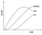
<突風応答低減の原理>
図2は一般的な翼型の揚力曲線を表す概念図で、S点を失速点、Aの領域をフロントサイド、Bの領域をバックサイドと称する。
Aの領域では、パイロットが操縦桿を引くと、姿勢が上を向き、短時間的には揚力が増加するために、機体が上昇する。これは、人間の感覚にとって自然な挙動である。長時間的には、飛行速度が低下するために揚力が減少し、機体は降下するが、本発明では動揺低減について述べるものであるから、短時間的な運動についてのみ考慮する。長時間的な運動については、エンジン出力を通常の操作で調節すればよい。
<Principle of reducing gust response>
FIG. 2 is a conceptual diagram showing a general airfoil lift curve, where point S is referred to as a stall point, region A is referred to as a front side, and region B is referred to as a back side.
In the area A, when the pilot pulls the control stick, the attitude turns upward and the lift increases in a short time, so that the aircraft rises. This is a natural behavior for human senses. In the long term, the lift decreases due to the decrease in flight speed, and the aircraft descends. However, since the present invention describes the reduction of sway, only short-term exercise is considered. For long-term exercise, the engine output may be adjusted by normal operation.
Bの領域では、Aの領域とは逆に、操縦桿を引くと揚力が減少して機体が降下するため、人間が操縦する場合には、特別な注意が必要である。通常は操縦桿を押して、Aの領域へ戻す操作を行う。必ずしも危険な領域ではなく、パワードリフト機などでは積極的に利用されることもある。 In the area B, contrary to the area A, when the control stick is pulled, the lift decreases and the aircraft descends, so special care is required when maneuvering by a human. Normally, the control stick is pushed to return to the area A. It is not always a dangerous area, and it may be actively used in power drift machines.
S点付近では、迎角の変化に対して、揚力係数の変化が少なく、鉛直風が変化したとしても揚力の変化が少ないため、機体の上下運動は抑えられる。ただし、A領域で飛行している際にS点に移行するために迎角を増加させると、機体が上昇してしまうため、水平飛行を維持するためには、揚力を適切に制御する必要がある。 In the vicinity of point S, the lift coefficient does not change much with respect to the change in the angle of attack, and even if the vertical wind changes, the lift does not change much, so the vertical movement of the aircraft is suppressed. However, if the angle of attack is increased to move to the S point while flying in the A region, the aircraft will rise, so it is necessary to properly control the lift in order to maintain horizontal flight. be.
揚力を制御する舵としては、例えばスポイラーが想定される。左右のエルロンを同相で変化させるフラッペロンでもよいし、両者を併用してもよい。 As a rudder that controls lift, for example, a spoiler is assumed. Flaperons that change the left and right ailerons in the same phase may be used, or both may be used in combination.
図3は、スポイラー角の変化によってどのように揚力係数が変化するかを模式的に示したものである。スポイラーを展開すると、揚力係数が減少するとともに、S点付近の揚力変化が少なくなる。
C点で巡航しているときに、迎角を増加させてS0点で飛行しようとすると揚力が増加するため機体は上昇する。この上昇を防ぐために、揚力係数がS2点になるようにスポイラーを展開すると、実際には迎角の増加に応じて抗力が増加して、飛行速度が低下するために揚力が減少して飛行高度が低下する。このため飛行高度を維持するために、S0点とS2点との間のS1点になるように、スポイラー角を制御すれば、水平飛行が可能であって、迎角の変化による揚力の変化が少ないため、鉛直風の変化による機体の動揺を低減することができるのである。準静的な制御であるため、機体の弾性変形の影響は生じない。
FIG. 3 schematically shows how the lift coefficient changes depending on the change in the spoiler angle. When the spoiler is deployed, the lift coefficient decreases and the lift change near the S point decreases.
When cruising at point C, if you try to fly at point S0 by increasing the angle of attack, the lift will increase and the aircraft will rise. In order to prevent this rise, if the spoiler is deployed so that the lift coefficient becomes S 2 points, the drag will actually increase as the angle of attack increases, and the lift will decrease due to the decrease in flight speed. The altitude drops. Therefore, in order to maintain the flight altitude, if the spoiler angle is controlled so that it becomes the S 1 point between the S 0 point and the S 2 point, horizontal flight is possible and the lift due to the change in the angle of attack is possible. Since there is little change in the air, it is possible to reduce the shaking of the aircraft due to changes in the vertical wind. Since it is a quasi-static control, it is not affected by the elastic deformation of the airframe.
巡航時は通常揚抗比が最大となる最も効率の良い迎角で飛行するため、迎角を変更するとそのまま同じ推力では水平飛行ができなくなることがある。S1点が時間とともに徐々にS0点近づき、やがてスポイラー角が0となっても降下するようになる場合は、スポイラー角が0となる前に推力を増加させる必要がある。推力の増加操作は、自動であっても手動であってもよい。通常はオートパイロットの機能に含まれている。 When cruising, it usually flies at the most efficient angle of attack, which maximizes the lift-to-drag ratio, so if the angle of attack is changed, horizontal flight may not be possible with the same thrust. If the S 1 point gradually approaches the S 0 point over time and eventually descends even if the spoiler angle becomes 0, it is necessary to increase the thrust before the spoiler angle becomes 0. The thrust increasing operation may be automatic or manual. It is usually included in the autopilot function.
前述のとおり、乱気流による機体動揺の程度は飛行速度に比例するものであるから、迎角の増大やスポイラーの展開により飛行速度が低下する結果として機体動揺が低減する相乗効果も期待できる。 As described above, since the degree of airframe sway due to turbulence is proportional to the flight speed, a synergistic effect of reducing the airframe sway can be expected as a result of the flight speed decreasing due to the increase in the angle of attack and the deployment of the spoiler.
前後風の変化による揚力の変化は、機体前方の前後風の計測値にあわせてスポイラー角を変化させて揚力の変化を相殺する。鉛直風の変化に対しては、準静的な制御であり、前後風の変化に対しては動的な制御であるため、両立は可能である。また、前後風による揚力の変化を相殺する制御は、典型的には揚力を発生する主翼に設置されたスポイラーで直接揚力を制御するものであるから、機体の弾性変形の影響を受けにくい。この点は、昇降舵の制御による揚力制御と大きく異なる利点である。 The change in lift due to the change in front and rear wind cancels the change in lift by changing the spoiler angle according to the measured value of the front and rear wind in front of the aircraft. Since it is a quasi-static control for changes in vertical wind and a dynamic control for changes in front-back wind, it is possible to achieve both. Further, the control for canceling the change in lift due to the front-rear wind is typically controlled by a spoiler installed on the main wing that generates lift, so that it is not easily affected by the elastic deformation of the airframe. This point is an advantage that is significantly different from lift control by controlling the elevator.
このような手法で、スポイラーを展開すると、揚抗比が低下して飛行の効率が低下する。しかしながら、本システムが作動するのは、ドップラーライダーで事前検知した乱気流に突入するときのみの一時的なものであることから、運航全体を通して考えた場合には、乱気流が想定される領域を大きく避けて飛行する必要がなくなるために、燃料の消費が少なくなることが期待される。あるいは同じ飛行経路の場合は、安全性の向上が期待できる。 Deploying the spoiler in this way reduces the lift-to-drag ratio and reduces flight efficiency. However, since this system operates only temporarily when it enters the turbulence detected in advance by the Doppler lidar, when considering the entire flight, the area where eddy is expected is largely avoided. It is expected that fuel consumption will be reduced because there is no need to fly. Alternatively, if the flight path is the same, improvement in safety can be expected.
本発明の一形態で利用するドップラーライダーによる観測のハードウェア上の制約として、観測可能な風速の範囲が制限されるということがある。このため、飛行機に搭載して使用する際には、飛行速度を差し引いて、差し引いた速度からの変化分を測定する手法がとられる。特許文献5では、直前観測値の平均値を飛行速度とみなしていたが、受信信号のSN比が高い場合でも観測値に異常値が含まれることがあるため、平均値では不都合があることが分かった。このため、本発明の一形態に係る飛行機の突風応答軽減システムでは、直前観測値のモード(最頻値)を飛行速度とみなす。
As a hardware limitation of observation by the Doppler lidar used in one embodiment of the present invention, the range of observable wind speed is limited. Therefore, when mounted on an airplane and used, a method is adopted in which the flight speed is subtracted and the amount of change from the subtracted speed is measured. In
モードを算出するためには、観測値を有限の風速範囲で分割してヒストグラムを生成する必要があるので、飛行速度計測値の分解能は風速の分割幅に依存することになる。ただし、風速観測可能範囲に入れば良いだけなので、飛行速度は概略でよい。 In order to calculate the mode, it is necessary to divide the observed value into a finite wind speed range to generate a histogram, so the resolution of the flight speed measurement value depends on the division width of the wind speed. However, since it is only necessary to enter the wind speed observable range, the flight speed may be approximate.
一方、飛行速度自体を計測する目的で使用する場合には、前記ヒストグラムから標準偏差に基づき異常値を除外し、正常な観測値のみの平均値を求めれば、信頼性と精度が高い飛行速度を求めることができる。 On the other hand, when using for the purpose of measuring the flight speed itself, if the abnormal value is excluded from the histogram based on the standard deviation and the average value of only the normal observed values is obtained, the flight speed with high reliability and accuracy can be obtained. You can ask.
揚力を制御する舵を動的に操作した場合の副作用として、一般的には機体の縦の姿勢角が変化する。縦の姿勢角の変化は飛行機の客室内の位置に応じて鉛直加速度を生ずる原因となるため、本発明の一形態に係る飛行機の突風応答軽減システムでは、縦の角加速度を低減させるために昇降舵を制御する機能を付加してもよい。 As a side effect of dynamically operating the rudder that controls lift, the vertical attitude angle of the aircraft generally changes. Since a change in the vertical attitude angle causes vertical acceleration depending on the position in the cabin of the airplane, in the gust response reduction system of the airplane according to one embodiment of the present invention, the elevator moves up and down in order to reduce the vertical angular acceleration. A function to control the rudder may be added.
乱気流事故は、鉛直加速度が負となって人員や物品が浮き上がり、鉛直加速度が正となったときに浮遊した人員や物品が落下して怪我をするのが典型的な状況である。したがって、本発明の一形態に係る飛行機の突風応答軽減システムでは、乱気流に突入する際に、旋回飛行を行い遠心力による加速度を重力加速度に重畳することにより事故を防止する制御機能を付加してもよい。 In an eddy accident, a typical situation is that a person or an article floats when the vertical acceleration becomes negative, and when the vertical acceleration becomes positive, the floating person or the article falls and is injured. Therefore, in the gust response mitigation system of an airplane according to one embodiment of the present invention, a control function is added to prevent an accident by performing a turning flight and superimposing the acceleration due to the centrifugal force on the gravitational acceleration when entering the eddy air. May be good.
一般的に乱気流域は高度方向の層状に分布する。したがって、高度変更中に乱気流層を通過することがしばしばある。本発明の一形態に係る飛行機の突風応答軽減システムでは、乱気流層への突入を防ぐために、高度変更中に前方の乱気流層を検知した場合には、自動的に高度変更を中断する制御機能を付加してもよい。 Generally, the eddy area is distributed in layers in the altitude direction. Therefore, it often passes through the eddy layer during altitude changes. In the gust response mitigation system for an airplane according to an embodiment of the present invention, in order to prevent the aircraft from entering the turbulence layer, a control function that automatically interrupts the altitude change when the turbulence layer in front is detected during the altitude change is provided. It may be added.
本発明で利用するドップラーライダーは、非常に弱い気流も観測可能であるが、観測誤差は避けることができない。このため、まったく乱気流がない場合にわずかな気流変化があるかのような信号を出力する可能性があり、その場合、機体を加振してしまう恐れがある。さらに、本発明による制御では飛行速度を低下させるため、制御の作動中は運航効率が低下する。したがって、観測された乱気流の強度が低い場合には揚力制御を行わず、ある閾値以上の場合に揚力制御を行うという基準が必要である。本発明の一形態に係る飛行機の突風応答軽減システムでは、乱気流の強度指標として、前述したρVWまたはPSVWを用いる。 The Doppler lidar used in the present invention can observe a very weak air flow, but an observation error cannot be avoided. Therefore, there is a possibility of outputting a signal as if there is a slight change in airflow when there is no turbulence at all, and in that case, there is a risk of shaking the aircraft. Further, since the control according to the present invention reduces the flight speed, the operation efficiency is reduced while the control is in operation. Therefore, it is necessary to have a standard that lift control is not performed when the intensity of the observed eddy is low, and lift control is performed when the strength is above a certain threshold. In the gust response mitigation system for an airplane according to one embodiment of the present invention, the above-mentioned ρVW or PSVW is used as the intensity index of the turbulence.
乱気流の強度は、以上の指標で定義できるが、飛行機の動揺の程度は各機体の空力特性や慣性力によって異なる。したがって、危険性を判定するためには、飛行機が動揺する程度も定義する必要がある。本発明の一形態に係る飛行機の突風応答軽減システムでは、乱気流事故に関連する可能性の少ない高い周波数の揺れと低い周波数の揺れの成分を除外し、一定時間連続する最大加速度の値を飛行機の動揺の程度の指標として用いる。 The intensity of eddy can be defined by the above indicators, but the degree of sway of the airplane depends on the aerodynamic characteristics and inertial force of each aircraft. Therefore, in order to judge the danger, it is necessary to define the degree to which the airplane is shaken. In the gust response mitigation system for an airplane according to an embodiment of the present invention, the components of high frequency sway and low frequency sway that are unlikely to be related to an eddy accident are excluded, and the value of the maximum acceleration continuously for a certain period of time is set for the airplane. It is used as an index of the degree of agitation.
個別の飛行機での乱気流の強度指標と動揺の程度の指標との対応は、飛行シミュレーションや飛行試験で明らかにすればよい。すなわち、制御が不要であるレベルの揺れや、緊急の対応が必要なレベルの揺れのときの乱気流の強度指標を調べて、制御則に反映させればよい。 The correspondence between the strength index of eddy and the index of the degree of sway in individual airplanes can be clarified by flight simulation or flight test. That is, the strength index of the eddy at the time of the level of shaking that does not require control or the level of shaking that requires urgent response may be investigated and reflected in the control rule.
風速を計測する計測部としてドップラーライダーを用いる場合には、光波の方向を変更するスキャナーに光学望遠鏡の集光機能を持たせることにより小型軽量化を実現する。該スキャナーは凸面のプリズム式であっても凹面のミラー式であってもよい。 When the Doppler lidar is used as the measuring unit for measuring the wind speed, the size and weight can be reduced by giving the scanner that changes the direction of the light wave the condensing function of the optical telescope. The scanner may be a convex prism type or a concave mirror type.
本発明によれば、単眼ライダーを用いた場合であっても、飛行機が乱気流に遭遇した際に機体の上下動揺を低減させることができ、飛行機の安全性や快適性の向上が期待できる。 According to the present invention, even when a monocular rider is used, it is possible to reduce the vertical sway of the airframe when the airplane encounters eddy, and it is expected that the safety and comfort of the airplane will be improved.
非特許文献3に示す耐空性審査要領第III部7-2-6Bでは、乱気流に突入する際の最大速度を定義しており、現状では乱気流が発生する可能性がある空域を飛行する際に減速する必要がある場合があるが、本発明によれば、乱気流を検知した時に減速すればよいため、運航効率や定時性の向上が期待できる。 The air resistance examination procedure Part III 7-2-6B shown in Non-Patent Document 3 defines the maximum speed when entering eddy, and at present, when flying in an airspace where eddy may occur. It may be necessary to decelerate, but according to the present invention, it is sufficient to decelerate when turbulence is detected, so that improvement in flight efficiency and punctuality can be expected.
以下、図面を参照しながら、本発明の実施形態を説明する
[突風応答軽減システムの構成]
図4は、本発明の一実施形態に係る飛行機に搭載される突風応答軽減システムの構成を示すブロック図である。
図4に示すように、この飛行機の突風応答軽減システムの制御コマンド生成部100は、計測部10と、制御演算部30とを備える。スキャナー300はレーザ光の放射方向を変更するための構成品であるが、本発明の実施に必須の構成品ではない。なぜなら、巡航中の飛行機の迎角や横滑り角は大きく変わることはなく、本発明の適用を近距離の乱気流への対応のみに限定した場合については、観測する領域が大きく変化することがないからである。
Hereinafter, embodiments of the present invention will be described with reference to the drawings [Structure of gust response mitigation system].
FIG. 4 is a block diagram showing a configuration of a gust response mitigation system mounted on an airplane according to an embodiment of the present invention.
As shown in FIG. 4, the control
<計測部>
計測部10は、大気中にレーザ光をパルス状に放射し、この反射光を受信し、放射したレーザ光と反射光との間の周波数のドップラーシフト量に基づき光軸方向(放射軸方向)の風速を計測するものであり、光学望遠鏡11と光送受信機12と信号処理部13とを有する。
<Measurement unit>
The measuring
光学望遠鏡11は、光送受信機12で生成されたレーザ光(送信光)を大気中に向けて放射する。放射されたレーザ光は、大気中に浮遊する微小なエアロゾル粒子によって散乱される。散乱光は、光学望遠鏡11を介して光送受信機12により受信される。
The
光送受信機12は、単一波長、例えば1.5μmのレーザ光を生成すると共に、その大気中での散乱光を受信して、放射したレーザ光と散乱光との間の周波数の差分を電気信号に変換する。
The optical transmitter /
信号処理部13は、周波数の差分信号を時分割して、距離ごとの風速を算出するものである。つまり、光学望遠鏡11を介して受信した受信光(散乱光)を送信光と比較し、ドップラー効果で生ずる周波数の変化から風速を求める。ドップラー効果による周波数変化量は典型的には風速の計測に用いられる。一般にこれはドップラーライダーと呼ばれており、ライダー(LIDAR)とは、光を利用した遠隔観測手法で「Light Detection And Ranging」を略したものである。最大観測距離は、およそ1~30kmで、この数値は大気条件により異なる。通常の旅客機であれば、この距離は4~150秒間の飛行距離に相当する。
The
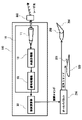
風速の算出にあたっては、一般的にハードウェア上の制限から前記周波数の計測可能範囲が限定されるため、図5に示すように真対気速度の概略値をオフセットとして利用する。このとき、前記周波数のドップラーシフト量は、FOFST+Fdである。試作した装置での風速の計測可能範囲は±40m/sである。 In calculating the wind speed, since the measurable range of the frequency is generally limited due to the limitation on the hardware, the approximate value of the true airspeed is used as an offset as shown in FIG. At this time, the Doppler shift amount of the frequency is F OFST + F d . The measurable range of wind speed with the prototype device is ± 40 m / s.
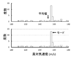
真対気速度の概略値を得る手法として、特許文献5では、直前観測値の平均値を真対気速度とみなしていたが、観測値には異常値が含まれることがあるため、図6に示すように平均値では誤差が大きくなることがあることが分かった。このため、本発明の一形態に係る飛行機の突風応答軽減システムでは、1~3秒間前の観測値のモード(最頻値)を真対気速度とみなす。このとき、受信信号のSN比が例えば7dB以上など信頼性が高い観測レンジのみについてモード(最頻値)を算出してもよい。
As a method for obtaining the approximate value of the true airspeed, in
モード(最頻値)を算出するためには、観測値を有限の風速範囲で分割してヒストグラムを生成する必要があるため、真対気速度計測値の分解能は風速の分割幅に依存することになる。前記風速の分割幅は2~5m/sが適しているので、前記分解能もその数値となる。ただし、風速観測可能範囲に入れば良いだけなので、真対気速度は分解能の低い概略値でよい。 In order to calculate the mode (mode), it is necessary to divide the observed value into a finite wind speed range to generate a histogram, so the resolution of the true airspeed measurement value depends on the division width of the wind speed. become. Since the division width of the wind speed is preferably 2 to 5 m / s, the resolution is also the numerical value. However, since it is only necessary to enter the wind speed observable range, the true airspeed may be an approximate value with low resolution.
本発明から派生的に生ずる機能として、真対気速度自体を計測する目的で使用する場合には、最新観測値の前記ヒストグラムから標準偏差に基づき例えば1σを超える異常値を除外し、正常な観測値のみの平均値を求めれば、信頼性と精度が高い真対気速度を求めることができる。静圧情報を用いれば、真対気速度を等価対気速度に変換することも可能である。 As a function derived from the present invention, when used for the purpose of measuring the true airspeed itself, normal observation is performed by excluding abnormal values exceeding 1σ based on the standard deviation from the histogram of the latest observed values. By finding the average value of only the values, it is possible to find the true airspeed with high reliability and accuracy. Using static pressure information, it is also possible to convert true airspeed to equivalent airspeed.
<制御演算部>
制御演算部30は、計測部10で計測した飛行予定方向の風速値に基づき、飛行機200が突風を受けることが判明した場合に、揚力傾斜が少ない迎角となるように昇降舵231の舵角コマンドをオートパイロット210に送信する。舵角変化は緩徐に行い、迎角をフィードバックして目標の迎角に設定する。加えて、揚力が変化しないようなスポイラー221の舵角コマンドをオートパイロット210に送信する。
<Control calculation unit>
Based on the wind speed value in the scheduled flight direction measured by the
揚力傾斜が最も少ない迎角は、揚力係数が最大値となる迎角であって、その迎角は、例えば非特許文献2に示されているように風洞試験で得ることができる。本発明を適用するためには、予めスポイラー角ごとの最大揚力係数とそのときの迎角を風洞試験等で調べておく必要がある。 The angle of attack with the smallest lift slope is the angle of attack at which the lift coefficient has the maximum value, and the angle of attack can be obtained by a wind tunnel test as shown in Non-Patent Document 2, for example. In order to apply the present invention, it is necessary to investigate the maximum lift coefficient for each spoiler angle and the angle of attack at that time by a wind tunnel test or the like in advance.
鉛直風WZの影響を低減させるために、乱気流に遭遇する3~10秒前に揚力係数が最大値となる迎角に向けて昇降舵231を自動的且つ緩徐に操作すると、機体は一時的に上昇するとともに飛行速度が低下する。このとき、昇降率をフィードバックしてスポイラー221の舵角を適切に増加させると、揚力と重量が釣り合って昇降率が0となる。その後時間とともにさらに飛行速度が低下して揚力が減少するが、スポイラー221の舵角制御には昇降率をフィードバックしているので、昇降率は0のままである。さらに時間が経過すると、スポイラー221の舵角が0になっても降下することがあるが、その前に推力を増加させて水平飛行を維持する。あるいは、運航上降下が許容される状況であれば、降下してもよい。
In order to reduce the influence of the vertical wind WZ , if the
スポイラー角に応じて最大揚力係数のときの迎角も若干変化するから、迎角を調節するための昇降舵231の制御にはスポイラー角をフィードバックする必要がある。
Since the angle of attack at the maximum lift coefficient also changes slightly depending on the spoiler angle, it is necessary to feed back the spoiler angle to control the
前後風WXの影響については、図7に示すように、スポイラー角1としてS1点となる迎角で飛行する場合、ドップラーライダーで観測される前方の風速をWXとすると、WX遭遇時の揚力係数を、数式8で得られるCL'とすることにより、WX遭遇前後の揚力を同一とすることができる。 Regarding the influence of the front and rear wind W X , as shown in Fig. 7, when flying at an angle of attack where the spoiler angle is 1 and S 1 point, if the wind speed in front observed by the Doppler lidar is W X , W X is encountered. By setting the lift coefficient at the time to CL'obtained by Equation 8, the lift before and after the encounter with WX can be made the same.
CL'=(V/(V+WX))2CL (8)
WXが正の場合はS2側で揚力係数がCL'となるようスポイラー角を増加させ、WXが負の場合はS0側で揚力係数がCL'となるようスポイラー角を減少させればよい。ドップラーライダーによる風速は距離ごとに独立して観測することができるため、時系列での風速変化がわかり、スポイラー角はその時系列にあわせて変更すればよい。加えて、観測は例えば5Hzの周期で更新されるので、新しい観測情報ほど重みを高くして、制御にロバスト性を持たせてもよい。
CL '= (V / (V + W X )) 2 CL (8)
If W X is positive, the spoiler angle is increased so that the lift coefficient is CL'on the S 2 side, and if W X is negative, the spoiler angle is decreased so that the lift coefficient is CL'on the S 0 side. Just let me do it. Since the wind speed by the Doppler lidar can be observed independently for each distance, the change in wind speed in time series can be known, and the spoiler angle can be changed according to the time series. In addition, since the observations are updated at a cycle of, for example, 5 Hz, the newer the observation information, the higher the weight, and the more robust the control may be.
揚力を制御する舵は、スポイラーではなくフラッペロンでもよい。あるいは、動揺低減用の専用舵であっても、高速で作動するフラップであってもよい。複数の舵を併用してもよい。 The rudder that controls lift may be a flaperon instead of a spoiler. Alternatively, it may be a dedicated rudder for reducing sway, or a flap that operates at high speed. Multiple rudders may be used together.
機体の動揺を低減する従来のフィードバック制御の場合、通常機体に取り付けられた加速度センサの出力に基づき舵角を制御する。この場合、図8に示すように、まず突風に遭遇してから機体が運動するまでは機体の慣性力で遅れる。さらに機体の運動を加速度センサで計測して、適切な舵角を計算してから、舵のアクチュエータに舵角コマンドを送信するが、舵の空気力が変更されるまででも遅れが生ずる。 In the case of conventional feedback control that reduces the shaking of the airframe, the steering angle is normally controlled based on the output of the acceleration sensor attached to the airframe. In this case, as shown in FIG. 8, there is a delay due to the inertial force of the airframe from the first encounter with the gust until the airframe moves. Furthermore, the motion of the aircraft is measured by the acceleration sensor, the appropriate rudder angle is calculated, and then the rudder angle command is sent to the rudder actuator, but there is a delay even until the aerodynamic force of the rudder is changed.
したがって、周波数が高い細かい揺れに対しては対応できないか、あるいは逆に加振してしまう可能性があった。 Therefore, there is a possibility that it is not possible to deal with small fluctuations with a high frequency, or conversely, vibration is performed.
これに対して、本発明に関する遠隔気流に基づく予見制御の場合は、遅れを見込んで事前に舵を制御することができるので、平均的な遅れの影響は発生せず、遠隔気流の観測誤差や舵角誤差などわずかな影響が残るだけである。したがって、周波数が高い細かい揺れに対しても対応できるため、事故低減だけでなく乗り心地の改善が期待できる。 On the other hand, in the case of the predictive control based on the remote airflow according to the present invention, since the rudder can be controlled in advance in anticipation of the delay, the influence of the average delay does not occur, and the observation error of the remote airflow and the observation error of the remote airflow occur. Only a slight effect such as steering angle error remains. Therefore, since it is possible to cope with small fluctuations with high frequencies, it is expected that not only the accidents will be reduced but also the riding comfort will be improved.
以上のようにスポイラーを動的に操舵した場合、縦のモーメント係数Cmが若干変化することがある。その結果ピッチングが発生して、飛行機の客室内の位置に応じて角加速度に比例した鉛直加速度を生ずる原因となるため、予めスポイラー角に応じたCmの変化量CmδSPを、風洞試験で求めておき、スポイラー角にあわせて昇降舵も変化させるとよい。 When the spoiler is dynamically steered as described above, the vertical moment coefficient C m may change slightly. As a result, pitching occurs, which causes vertical acceleration proportional to the angular acceleration according to the position in the cabin of the airplane. It is advisable to change the elevator according to the spoiler angle.
具体的には、図9に示すようなスポイラー角に応じたCmの変化量CmδSP、および昇降舵角に応じたCmの変化量CmδELの特性を予め求めておく。ある時点のスポイラー角がδSP1であるとして、スポイラー角をδSP2量に変化させるというコマンドが本発明に係わる制御のために発出された場合、CmはδCmだけ変化するので、このモーメントを相殺するために、その時点の昇降舵角がδEL1である場合には、逆のモーメントを発生させるδEL2に昇降舵角がなるようなコマンドを同時に発出する。本発明に係る迎角の変更のための昇降舵角制御は準静的な制御であり、縦のモーメント相殺のための昇降舵角制御は動的な制御であるため、両立は可能である。 Specifically, the characteristics of the change amount C m δ SP of C m according to the spoiler angle and the change amount C m δ EL of C m according to the elevator angle as shown in FIG. 9 are obtained in advance. Assuming that the spoiler angle at a certain point in time is δ SP1 , if a command to change the spoiler angle to the amount of δ SP2 is issued for the control according to the present invention, C m changes by δ Cm , so this moment is used. To offset, if the elevator angle at that time is δ EL1 , a command is issued at the same time so that the elevator angle becomes δ EL2 that generates the opposite moment. Since the elevator angle control for changing the angle of attack according to the present invention is a quasi-static control and the elevator angle control for canceling the vertical moment is a dynamic control, both are possible.
CmδSPは、飛行試験で求めてもよい。角加速度を抑制するために角加速度センサの信号をフィードバックして昇降舵を制御する従来の機能を利用してもよい。 C m δ SP may be obtained by a flight test. In order to suppress the angular acceleration, the conventional function of feeding back the signal of the angular acceleration sensor to control the elevator may be used.
鉛直加速度が負となることを抑制するために、前方の乱気流を検知した場合に制御演算部30は、オートパイロット210に旋回コマンドを送信してもよい。例えば通常の旅客機の運航で許容される30度バンクで旋回した場合、垂直加速度が約15%増加するため、人員や物品が浮き上がる可能性を低減させることができる。
In order to suppress the vertical acceleration from becoming negative, the
例えば特許文献6の技術を用いて、左右の旋回方向を判定し、少しでも乱気流が弱い方向に回避するための旋回飛行を行ってもよい。 For example, the technique of Patent Document 6 may be used to determine the left and right turning directions, and the turning flight may be performed to avoid the direction in which the turbulence is weak as much as possible.
高度変更中に前方の乱気流層を検知した場合には、制御演算部30は、オートパイロット210に高度変更中止のコマンドを送信してもよい。図10に示すように乱気流域は高度方向の層状に分布することが多く、これをドップラーライダーで事前検知した場合、高度変更を中止すれば、乱気流層への突入を回避することが可能となる。上昇中であっても降下中であっても同様である。
When the eddy layer in front is detected during the altitude change, the
対処すべき乱気流であるかどうかの判定基準としては、前述したρVWまたはPSVWを乱気流の強度指標として用いる。特にPSVWの場合、PSは気圧高度計に利用する静圧であるため利用しやすい。風速変化量Wは乱気流に等方性があるとみなして、前記光軸方向風速変化量をWとする。VWは、特許文献4の「乱気流の検知方法」に示されるFh-ファクタを用いて、求めることができる。ただし、Fh-ファクタでは2回の計測値の差分を計算する関係上、2回の計測値のどちらか一方あるいは両方が計測不良である場合には不正な数値が算出されてしまう。このため、1回の計測でWを求める手法として、特許文献7の「遠隔乱気流検知方法およびそれを実施する装置」では、受信信号のスペクトル幅を用いることとした。しかし、現実のレーザ装置では、送信信号のスペクトル幅が0ではないために、風速幅の推定に誤差が生じることが判明した。 As a criterion for determining whether or not the turbulence should be dealt with, the above-mentioned ρVW or PS VW is used as an intensity index of the turbulence. Especially in the case of PS VW , PS is easy to use because it is the static pressure used for the barometric altimeter . The amount of change in wind speed W is considered to be isotropic in the eddy, and the amount of change in wind speed in the optical axis direction is defined as W. VW can be obtained by using the Fh-factor shown in "Method for detecting turbulence" in Patent Document 4. However, in the Fh-factor, since the difference between the two measured values is calculated, if either or both of the two measured values are poorly measured, an invalid value will be calculated. Therefore, as a method for obtaining W in one measurement, the spectral width of the received signal is used in the "remote eddy detection method and the device for carrying out the remote eddy detection method" in Patent Document 7. However, in an actual laser device, it has been found that an error occurs in the estimation of the wind speed width because the spectral width of the transmitted signal is not zero.
上記の問題を解決するために本発明では、前記光軸方向風速変化量Wとして、光送受信機12が受信した散乱光のパワースペクトル幅から送信光のパワースペクトル幅を差し引いたもの、すなわち散乱によるパワースペクトル幅の増加量が前記光軸方向風速変化量に比例するものとする。したがって、前記光軸方向風速変化量W(レンジビン内の風速の標準偏差)は、以下で与えられる。
In order to solve the above problem, in the present invention, the amount of change in wind velocity in the optical axis direction W is obtained by subtracting the power spectrum width of the transmitted light from the power spectrum width of the scattered light received by the optical transmitter /
W=λ(fdr-fdt)2 (9)
ここで、λはレーザ光の波長、fdrは受信光のパワースペクトル幅、fdtは送信光のパワースペクトル幅である。なお、Wは風速の標準偏差であるから、風速変化量に比例する。
PsVWのうち、Vは本発明による真対気速度の値でもよいし、飛行機に通常搭載されている対気速度計から求めてもよい。
W = λ (fdr-fdt) 2 (9)
Here, λ is the wavelength of the laser light, fdr is the power spectrum width of the received light, and fdt is the power spectrum width of the transmitted light. Since W is the standard deviation of the wind speed, it is proportional to the amount of change in the wind speed.
Of Ps VW, V may be the value of the true airspeed according to the present invention, or may be obtained from the airspeed indicator normally mounted on an airplane.
Wが観測精度以下の気流変化(例えば0.22m/s以下)の場合は、舵面制御により逆に加振する可能性があるため、気流変化を観測しても制御を実施しない方が妥当である。あるいは、観測された気流変化量に応じて制御ゲインを変化させてもよい。 If the airflow change is less than the observation accuracy (for example, 0.22 m / s or less), it may be vibrated in the opposite direction by the control surface control, so it is appropriate not to perform the control even if the airflow change is observed. Is. Alternatively, the control gain may be changed according to the observed amount of change in airflow.
乱気流の強度は、以上の指標で定義できるが、飛行機の動揺の程度は各機体の空力特性や慣性力によって異なる。したがって、飛行機が動揺する程度にも指標が必要である。本発明の一形態に係る飛行機の突風応答軽減システムでは、例えば、乱気流事故に関連する可能性の少ない高い周波数として2Hz以上の揺れ、低い周波数として0.1Hz以下の揺れの成分を除外し、図11に示すように0.3秒間連続する最大加速度aの値を飛行機の動揺の程度の指標として用いる。前記最大加速度aは対数で表してもよい。 The intensity of eddy can be defined by the above indicators, but the degree of sway of the airplane depends on the aerodynamic characteristics and inertial force of each aircraft. Therefore, an index is also necessary to the extent that the airplane is shaken. In the gust response mitigation system for an airplane according to an embodiment of the present invention, for example, the components of shaking of 2 Hz or higher as a high frequency and shaking of 0.1 Hz or lower as a low frequency, which are unlikely to be related to an eddy accident, are excluded. As shown in No. 11, the value of the maximum acceleration a that is continuous for 0.3 seconds is used as an index of the degree of sway of the airplane. The maximum acceleration a may be expressed in logarithms.
個別の飛行機での乱気流の強度指標と動揺の程度の指標との対応は、飛行シミュレーションや飛行試験で明らかにすればよい。すなわち、乱気流の強度指標と実際に発生した加速度との相関係数を求め、人間の感覚に合わせた閾値を決定すればよい。本発明に係る飛行機の突風応答軽減システムによる舵面制御を実施した場合、運航効率の低下が避け難いため、推定される揺れが少ない場合は、対応しないという選択肢があり得る。 The correspondence between the strength index of eddy and the index of the degree of sway in individual airplanes can be clarified by flight simulation or flight test. That is, the correlation coefficient between the intensity index of the turbulence and the actually generated acceleration may be obtained, and the threshold value according to the human sense may be determined. When the control surface is controlled by the gust response mitigation system of the airplane according to the present invention, it is unavoidable that the operation efficiency is lowered. Therefore, if the estimated shaking is small, there may be an option not to deal with it.
[突風応答軽減システムの使用例]
本発明に係る飛行機の突風応答軽減システムの使用例を、図12のフローチャートで説明する。
本発明に係る前方気流観測(S1)は飛行中常時実施していて、飛行機から出力されるピトー・静圧情報(S2)も含めて乱気流強度指標を算出するが(S3)、乱気流強度指標が事前に設定した閾値未満の場合は、対処不要として本発明に係る動揺低減制御を実施しない。閾値以上の場合には動揺低減制御(S4)を実施し、揚力傾斜が少ない迎角を指定するコマンド、昇降率を0とする揚力コマンド及び昇降舵で縦のモーメントを相殺するコマンドをオートパイロットに発出する。同時に乱気流強度指標と機体諸元(S5)から機体動揺指標を算出して(S6)、機体動揺指標が事前に設定した閾値未満の場合は、緊急性なしとして旋回や高度変更中止などの緊急回避制御を実施しない。機体諸元は、機体重量、飛行速度、空力データなどである。閾値以上の場合には緊急回避制御を実施し(S7)、高度変更中であれば高度変更中止コマンドを、高度変更中でなければ旋回コマンドをオートパイロットに発出する。実際に乱気流を回避できなかった場合でも、本発明に係る動揺低減制御や旋回による垂直加速度の重畳が有効に作用して、事故を低減させることができる。緊急回避についてはパイロットの判断が介在してもよい。
[Example of using gust response mitigation system]
An example of using the airplane gust response mitigation system according to the present invention will be described with reference to the flowchart of FIG.
The forward airflow observation (S1) according to the present invention is always carried out during flight, and the turbulence intensity index is calculated including the pitot / static pressure information (S2) output from the airplane (S3), but the turbulence intensity index is If it is less than the preset threshold, the sway reduction control according to the present invention is not performed because no action is required. If it is above the threshold, the sway reduction control (S4) is executed, and the autopilot is given a command to specify an angle of attack with a small lift tilt, a lift command to set the lift rate to 0, and a command to cancel the vertical moment with the elevator. Issue. At the same time, the eddy strength index and the aircraft specifications (S5) are used to calculate the aircraft sway index (S6). No control is performed. Airframe specifications include airframe weight, flight speed, and aerodynamic data. If it exceeds the threshold value, emergency avoidance control is performed (S7), and if the altitude is being changed, an altitude change stop command is issued, and if the altitude is not being changed, a turning command is issued to the autopilot. Even if the turbulence cannot be actually avoided, the sway reduction control and the superposition of the vertical acceleration by turning according to the present invention can effectively act to reduce the accident. The pilot's judgment may intervene for emergency avoidance.
なお、離着陸時の低高度では大気中のエアロゾル粒子の密度が高くドップラーライダーの観測距離が長い、乗員乗客がシートベルトを着用している、パイロット単独の判断で飛行経路の変更ができる、本発明に係る制御に不具合が生じた場合に高度低下のリスクがある、ことから、例えば500m以下の飛行高度では、本発明に係る制御を行うよりも、単にパイロットに乱気流の事前情報を提供するだけの運用の方が望ましい。 At low altitudes during takeoff and landing, the density of aerosol particles in the atmosphere is high and the observation distance of the Doppler lidar is long, the passengers and passengers are wearing seat belts, and the flight path can be changed at the discretion of the pilot alone. Since there is a risk of altitude drop in the event of a malfunction in the control according to the above, for example, at a flight altitude of 500 m or less, rather than performing the control according to the present invention, it merely provides the pilot with prior information on the turbulence. Operation is preferable.
[システムの搭載]
ドップラーライダーは、極めて弱い散乱光を受信するので、光学望遠鏡11の口径が大きいほど性能が向上する。例えば口径を150mmとした場合、試作した光アンテナ40(図13参照)の重量は約50kgで、光軸の方位を変更するためのプリズム式スキャナー301(図13参照)の重量は約45kgであった。これらは図13に示すように前後に配置された。図の左側が機首方向である。チャンバー242は光アンテナ40を機内と同様に与圧するためのもので、チャンバーウインドウ243を通して光が放出される。スキャナー301は電動モータで回転可能なプリズムを二重に配置しており、光の向きを自由に変えることができる。フェアリングウインドウ241は、これらの機器を収納するフェアリング240の前面に取り付けられた窓である。口径150mmの大型光学望遠鏡を光アンテナに配置する際には、高い剛性が必要で、構造的に軽量化は困難である。しかも、光学望遠鏡11に使われるレンズは、極めて高い光学特性が必要なため、フレネルレンズ等で軽量化することはできない。
[Installation of system]
Since the Doppler lidar receives extremely weak scattered light, the larger the aperture of the
図14のAは従来の構成であるが、これをBに示すように、光学望遠鏡11の対物レンズを省略し、スキャナー302のプリズムを凸面にすることにより、対物レンズの働きを兼用するようにする。対物レンズが不要となれば、対物レンズの重量のみならず、対物レンズを支持する構造体も不要になり、光アンテナ筐体自体も小型化できるので、軽量化が可能となる。あるいは、Cのようにフェアリングウインドウ303を凸レンズにして対物レンズの働きを兼用するようにし、小型凹レンズ304を移動させることによりレーザビームの方向を変更する機構としてもよい。このとき、レーザの光軸は常にフェアリングウインドウ303の中心に向かうような機構を採用する。フェアリングウインドウ303は強度が必要なため2cm以上の厚みとなり、凸レンズにすることは容易であるし、スキャナー300よりフェアリングウインドウ303が外側にあることにより、レーザビームが欠けないようにするためにフェアリングウインドウ303のサイズを大きくする必要もなくなる。スキャナー300が不要になることの重量低減効果も大きい。
A of FIG. 14 has a conventional configuration, but as shown in B, the objective lens of the
該小型凹レンズ304を移動させる具体的な機構の例を図15に示す。凸面フェアリングウインドウ303の枠に迎角変更支持具311が取り付けられており、光軸310が仰角方向に変化しても、光軸310が常に凸面フェアリングウインドウ303の中心を向くようになっている。方位の変更は方位変更支持具312を回転させることにより実現でき、小型凹レンズ304が先端に取り付けられた光送受信部314は方位変更支持具312に固定されているため、迎角変更支持具311のスリット311Sに沿って横方向に動くため、光軸310は常に凸面フェアリングウインドウ303の中心を向く。この方式の場合、送受信光の伝達に光ファイバケーブル315を使うと高出力光には向かなくなるが構造が単純になり、光送受信部を圧力隔壁250より外側のレドーム内などの非与圧部に配置することが可能となる。その結果、チャンバー242やチャンバーウインドウ243も不要となる(図13参照)。なお、通常の設計では光ファイバケーブル315出口で拡散する出力光を、まず凸レンズで平行光線にするので、出力光を凸面フェアリングウインドウ303の口径に合わせて拡散させるために304は凹レンズとなるが、前記凸レンズと304を一体化させて凸レンズとしてもよい。
An example of a specific mechanism for moving the small
一方、小型凹レンズ304を移動させるのではなく、図16に示すように複数の光送受信部314を装備すれば、同時に複数の方向を観測することができる。この場合、光ファイバケーブル315は複数となるため、等価的に高出力の光を放出することもできる。
On the other hand, if the small
スキャナー300はプリズム式ではなく、ミラー式の場合でも図17に示すように凹面鏡305にすれば対物レンズの代わりとなる。光軸を変更させるためには、凹面鏡305を回転させればよい。
Even if the
図17に示す該凹面鏡305を回転させてレーザビーム方向を変更する場合、フェアリングの寸法に余裕が必要なため、機外の張り出しが大きくなり、空気抵抗や空力騒音が大きくなる可能性がある。このため、図18に示すように小型凸面鏡306を前後に動かすと同時に光軸が該凹面鏡305の中心を向くように該小型凸面鏡306を回転させることにより、レーザビームのエレベーション(仰角)を変更する機構としてもよい。レーザビームのアジマス(方位)を変更するには、該凹面鏡305をアジマス方向に回転させる機構としてもよい。
When the
該小型凸面鏡306を、ラックギア307と減速ギア308を用いて前後移動と同時に回転させる具体的な機構の例を図19に示す。該ラックギア307は機体に固定されており、該減速ギア308の支持具309を前後に移動させると該小型凸面鏡306が回転する。該減速ギア308のギア比を適切に設定すれば、光軸310が常に該凹面鏡305の中心を向くように設計することが可能である。このとき該小型凸面鏡306の角度変化量の微調整が必要な場合には、該減速ギア308に楕円ギアを用いてもよい。
FIG. 19 shows an example of a specific mechanism for rotating the small
該小型凸面鏡306を、リンク機構を用いて前後移動と同時に回転させる具体的な機構の例を図20に示す。該小型凸面鏡306を前後に移動させると、P点は支持具に開けられた長穴309hに沿って直線運動をするが、L1がL2より短いために該小型凸面鏡306は回転運動を伴う。このときL1とL2の長さの比を適切に設定することにより、光軸が常に該凹面鏡305の中心付近を向くように設計することが可能である。
FIG. 20 shows an example of a specific mechanism for rotating the small
[その他]
旅客機の事故原因の半数以上は乱気流が関係しており、乱気流事故を減らすことは喫緊の課題である。このため、旅客機の場合、気象レーダーの装備が義務付けられており、乱気流を発生させる積乱雲の発見は可能だが、晴天状態で発生する乱気流は検知できない。
[others]
Eddy is involved in more than half of the causes of passenger aircraft accidents, and reducing eddy accidents is an urgent issue. For this reason, in the case of passenger aircraft, it is obligatory to equip a weather radar, and although it is possible to detect cumulonimbus clouds that generate turbulence, eddy generated in fine weather cannot be detected.
これに対して、ドップラーライダーは晴天時に遠隔気流が観測できるという特長があるものの、有効観測レンジの短さが運航会社のパイロットから指摘されており、実用化の足かせとなっていた。しかし、1km程度の短い観測レンジであっても、本発明の突風応答軽減システムは、飛行機が乱気流に遭遇した場合の機体動揺を低減させる手段として好適に適用することが出来る。 On the other hand, although Doppler lidar has the advantage of being able to observe remote airflow in fine weather, the short effective observation range has been pointed out by pilots of operating companies, which has been a hindrance to practical application. However, even in a short observation range of about 1 km, the gust response mitigation system of the present invention can be suitably applied as a means for reducing airframe sway when an airplane encounters turbulence.
以上は電磁波の一種である光波を用いるドップラーライダーの利用を前提に本発明を説明したが、電波を用いるドップラーレーダーにも適用できる。 Although the present invention has been described above on the premise of using a Doppler lidar that uses a light wave, which is a kind of electromagnetic wave, the present invention can also be applied to a Doppler radar that uses radio waves.
10 計測部
11 光学望遠鏡
12 光送受信機
13 信号処理部
30 制御演算部
40 光アンテナ
100 制御コマンド生成部
200 飛行機
210 オートパイロット
221 スポイラー
231 昇降舵
240 フェアリング
241 フェアリングウインドウ
242 チャンバー
243 チャンバーウインドウ
250 圧力隔壁
300、301、302 スキャナー
303 フェアリングウインドウ
304 小型凹レンズ
305 凹面鏡
306 小型凸面鏡
307 ラックギア
308 減速ギア
309 支持具
309h 長穴
310 光軸
311 迎角変更支持具
311S スリット
312 方位変更支持具
314 光送受信部
315 光ファイバケーブル
10 Measuring
Claims (11)
飛行機の揚力を制御する舵と、
前記計測部での計測結果に基づき、前記飛行機が突風を受けることが判明した場合に、前記突風による迎角変化がもたらす第1の揚力変化を空気密度又は静圧と飛行速度と突風の鉛直成分との積に基づき算出し、前記算出された第1の揚力変化に基づき揚力傾斜が少ない迎角を算出するとともに、突風による動圧変化がもたらす第2の揚力変化を空気密度又は静圧と飛行速度と突風の前後成分との積に基づき算出し、前記算出された第2の揚力変化に基づき揚力が変化しないような前記揚力を制御する舵の角度を算出する制御演算部と
を具備する飛行機の突風応答軽減システム。 Electromagnetic waves are radiated toward the planned flight direction of the aircraft, the scattered waves in the atmosphere are received, and the remote wind in the direction of the radiation axis is based on the Doppler shift amount of the frequency between the radiated electromagnetic waves and the scattered electromagnetic waves. And the measuring unit that measures
The rudder that controls the lift of the airplane,
Based on the measurement results of the measuring unit, when it is found that the airplane receives a gust, the first lift change caused by the angle of attack change due to the gust is the air density or static pressure, the flight speed, and the vertical component of the gust. Calculated based on the product of An airplane equipped with a control calculation unit that calculates based on the product of the speed and the front and rear components of the gust, and calculates the angle of the steering that controls the lift so that the lift does not change based on the calculated second lift change. Gust response mitigation system.
前記計測部は、風速測定範囲を特定する真対気速度を得るために、各レンジビンの各風速計測値のヒストグラム上のモードを求める信号処理部を有する
飛行機の突風応答軽減システム。 The airplane gust response mitigation system according to claim 1.
The measurement unit is an airplane gust response mitigation system having a signal processing unit that obtains a mode on a histogram of each wind speed measurement value of each range bin in order to obtain a true airspeed that specifies a wind speed measurement range.
空力データに基づき、昇降舵を自動制御して飛行機の角加速度を小さくする機能
を具備する飛行機の突風応答軽減システム。 The airplane gust response mitigation system according to claim 1 or 2.
An airplane gust response mitigation system that has the function of automatically controlling the elevator and steering to reduce the angular acceleration of an airplane based on aerodynamic data.
旋回によって正の垂直加速度を重力加速度に重畳する機能
を具備する飛行機の突風応答軽減システム。 The airplane gust response mitigation system according to claim 1 or 2.
Airplane gust response mitigation system with the ability to superimpose positive vertical acceleration on gravitational acceleration by turning.
高度変更中に乱気流層を検知した場合に、高度変更を自動的に中断する機能
を具備する飛行機の突風応答軽減システム。 The airplane gust response mitigation system according to claim 1 or 2.
An airplane gust response mitigation system with the ability to automatically interrupt altitude changes when an eddy layer is detected during altitude changes.
前記制御演算部は、乱気流の強度指標として、放射する電磁波の放射軸方向の風速変化量および飛行速度ならびに空気密度または静圧の積を用いる
飛行機の突風応答軽減システム。 The airplane gust response mitigation system according to claims 1 to 5.
The control calculation unit is an airplane gust response mitigation system that uses the product of the amount of change in wind speed and flight speed in the direction of the radiation axis of the radiated electromagnetic wave and the air density or static pressure as the intensity index of the eddy wave.
前記制御演算部は、前記放射軸方向の風速変化量として、レンジビン内における散乱のパワースペクトル幅の増加量から該レンジビン内の風速幅を求め、該風速幅により乱気流の強度を数値で表す
飛行機の突風応答軽減システム。 The airplane gust response mitigation system according to claim 6.
The control calculation unit obtains the wind speed width in the range bin from the increase in the power spectrum width of scattering in the range bin as the wind speed change amount in the radiation axis direction, and numerically expresses the intensity of the eddy by the wind speed width. Gust response mitigation system.
前記制御演算部は、飛行機が動揺する程度の指標として、揺れの周波数の高い成分と低い成分を取り除き、一定時間連続する最大加速度の値を用いる
飛行機の突風応答軽減システム。 The airplane gust response mitigation system according to claims 1 to 7.
The control calculation unit is an airplane gust response mitigation system that uses the value of the maximum acceleration that is continuous for a certain period of time by removing the high and low frequency components of the sway as an index of the degree to which the airplane sways.
前記計測部は、放射する電磁波として光波を用い、
前記光波の方向を変更し、かつ、光学望遠鏡の集光機能を有するスキャナーをさらに具備する
飛行機の突風応答軽減システム。 The airplane gust response mitigation system according to claims 1 to 8.
The measuring unit uses light waves as radiated electromagnetic waves.
An airplane gust response mitigation system further comprising a scanner that changes the direction of the light wave and has a light-collecting function of an optical telescope.
前記計測結果に基づき、前記飛行機が突風を受けることが判明した場合に、前記突風による迎角変化がもたらす第1の揚力変化を空気密度又は静圧と飛行速度と突風の鉛直成分との積に基づき算出し、前記算出された第1の揚力変化に基づき揚力傾斜が少ない迎角を算出するとともに、突風による動圧変化がもたらす第2の揚力変化を空気密度又は静圧と飛行速度と突風の前後成分との積に基づき算出し、前記算出された第2の揚力変化に基づき揚力が変化しないような前記揚力を制御する前記飛行機の舵の角度を算出する
飛行機の突風応答軽減方法。 Electromagnetic waves are radiated toward the planned flight direction of the aircraft, the scattered waves in the atmosphere are received, and the remote wind in the direction of the radiation axis is based on the Doppler shift amount of the frequency between the radiated electromagnetic waves and the scattered electromagnetic waves. Measure and
Based on the measurement results, when it is found that the airplane receives a gust, the first lift change caused by the angle of attack change due to the gust is the product of air density or static pressure, flight speed, and the vertical component of the gust. Based on the calculated first lift change, the angle of attack with a small lift slope is calculated, and the second lift change caused by the dynamic pressure change due to the gust is the air density or static pressure, flight speed, and gust. A method for reducing the gust response of an airplane, which is calculated based on the product of the front-rear components and calculates the angle of attack of the steering wheel of the airplane that controls the lift so that the lift does not change based on the calculated second lift change .
前記制御演算部は、フロントサイドの領域、失速点及びバックサイドの領域を有する揚力曲線のうち、前記失速点付近に対応する前記迎角を算出し、前記算出された迎角を増加による機体の上昇を抑え、水平飛行を維持するように、前記揚力を制御する舵の角度を算出する
飛行機の突風応答軽減システム。 The airplane gust response mitigation system according to any one of claims 1 to 9.
The control calculation unit calculates the angle of attack corresponding to the vicinity of the stall point in the lift curve having the front side region, the stall point, and the back side region, and increases the calculated angle of attack of the aircraft. An airplane gust response mitigation system that calculates the angle of attack that controls lift to reduce climb and maintain level flight.
Priority Applications (4)
| Application Number | Priority Date | Filing Date | Title |
|---|---|---|---|
| JP2018072705A JP7097052B2 (en) | 2018-04-04 | 2018-04-04 | Airplane gust response mitigation system and airplane gust response mitigation method |
| EP19780631.8A EP3778386A4 (en) | 2018-04-04 | 2019-03-29 | Aircraft gust response reduction system, turbulence sensing system, shake estimation system, doppler lidar, and aircraft gust response reduction method |
| PCT/JP2019/014210 WO2019194103A1 (en) | 2018-04-04 | 2019-03-29 | Aircraft gust response reduction system, turbulence sensing system, shake estimation system, doppler lidar, and aircraft gust response reduction method |
| US17/043,427 US11827337B2 (en) | 2018-04-04 | 2019-03-29 | Gust alleviation system of airplane, turbulence detection system, fluctuation estimation system, doppler LIDAR, and gust alleviation method of airplane |
Applications Claiming Priority (1)
| Application Number | Priority Date | Filing Date | Title |
|---|---|---|---|
| JP2018072705A JP7097052B2 (en) | 2018-04-04 | 2018-04-04 | Airplane gust response mitigation system and airplane gust response mitigation method |
Publications (3)
| Publication Number | Publication Date |
|---|---|
| JP2019182075A JP2019182075A (en) | 2019-10-24 |
| JP2019182075A5 JP2019182075A5 (en) | 2021-04-22 |
| JP7097052B2 true JP7097052B2 (en) | 2022-07-07 |
Family
ID=68100361
Family Applications (1)
| Application Number | Title | Priority Date | Filing Date |
|---|---|---|---|
| JP2018072705A Active JP7097052B2 (en) | 2018-04-04 | 2018-04-04 | Airplane gust response mitigation system and airplane gust response mitigation method |
Country Status (4)
| Country | Link |
|---|---|
| US (1) | US11827337B2 (en) |
| EP (1) | EP3778386A4 (en) |
| JP (1) | JP7097052B2 (en) |
| WO (1) | WO2019194103A1 (en) |
Cited By (1)
| Publication number | Priority date | Publication date | Assignee | Title |
|---|---|---|---|---|
| WO2024048101A1 (en) * | 2022-09-02 | 2024-03-07 | 国立研究開発法人宇宙航空研究開発機構 | Aircraft automatic control system, method for evaluating effectiveness thereof, and measuring device for said automatic control system |
Families Citing this family (7)
| Publication number | Priority date | Publication date | Assignee | Title |
|---|---|---|---|---|
| WO2019207720A1 (en) * | 2018-04-26 | 2019-10-31 | 三菱電機株式会社 | Laser radar device, wind power generator, and wind measurement method |
| US11656632B2 (en) * | 2019-07-12 | 2023-05-23 | The Boeing Company | Takeoff/landing stability augmentation by active wind gust sensing |
| JP7458052B2 (en) | 2019-11-14 | 2024-03-29 | 国立研究開発法人宇宙航空研究開発機構 | Turbulence sensing system, aircraft and turbulence sensing method |
| CN111965667B (en) * | 2020-10-14 | 2020-12-29 | 南京牧镭激光科技有限公司 | Dynamic compensation wind measurement laser radar system and wind measurement method thereof |
| CN113212733B (en) * | 2021-04-30 | 2022-05-10 | 成都飞机工业(集团)有限责任公司 | Large-aspect-ratio conventional-layout unmanned aerial vehicle gust load alleviation method |
| CN114355480B (en) * | 2021-12-15 | 2023-12-22 | 中国飞行试验研究院 | Gust load test flight weather forecast guaranteeing method |
| CN115783247A (en) * | 2022-11-11 | 2023-03-14 | 中国航空工业集团公司西安飞行自动控制研究所 | Active control method for improving longitudinal riding quality |
Citations (6)
| Publication number | Priority date | Publication date | Assignee | Title |
|---|---|---|---|---|
| JP2010509118A (en) | 2006-11-11 | 2010-03-25 | エアバス・オペレーションズ・ゲーエムベーハー | Aircraft wing high lift system and operation method thereof |
| JP2011185773A (en) | 2010-03-09 | 2011-09-22 | Japan Aerospace Exploration Agency | Optical air data sensor |
| US20110291879A1 (en) | 2009-02-06 | 2011-12-01 | Thales | System and method for detecting and determining remote atmospheric anomalies |
| US20160114903A1 (en) | 2014-10-24 | 2016-04-28 | King Abdullah University Of Science And Technology | Flight envelope protection system for unmanned aerial vehicles |
| WO2016181493A1 (en) | 2015-05-12 | 2016-11-17 | 三菱電機株式会社 | Laser radar device and wind speed observation method |
| WO2017041018A1 (en) | 2015-09-02 | 2017-03-09 | Jetoptera, Inc. | Fluidic propulsive system and thrust and lift generator for aerial vehicles |
Family Cites Families (26)
| Publication number | Priority date | Publication date | Assignee | Title |
|---|---|---|---|---|
| JPS5331026A (en) | 1976-09-03 | 1978-03-23 | Hitachi Ltd | Injection carburetter |
| US4171115A (en) | 1977-12-12 | 1979-10-16 | Sperry Rand Corporation | Stability augmentation system for relaxed static stability aircraft |
| US4894658A (en) * | 1983-11-04 | 1990-01-16 | Motorola, Inc. | Method of data reduction in non-coherent side-looking airborne radars |
| US5237331A (en) * | 1992-05-08 | 1993-08-17 | Henderson Sammy W | Eyesafe coherent laser radar for velocity and position measurements |
| US6246929B1 (en) * | 1999-06-16 | 2001-06-12 | Lockheed Martin Corporation | Enhanced stall and recovery control system |
| JP2001039397A (en) * | 1999-08-02 | 2001-02-13 | Komatsu Ltd | Flying body having horizontal rotary wing |
| DE10106516A1 (en) * | 2001-02-13 | 2002-09-05 | Astrium Gmbh | Procedure for the simulation of variable accelerations |
| JP3740525B2 (en) * | 2001-07-05 | 2006-02-01 | 独立行政法人 宇宙航空研究開発機構 | Wind disturbance prediction system |
| US8072584B2 (en) * | 2002-08-02 | 2011-12-06 | Ophir Corporation | Optical air data systems and methods |
| US20090048723A1 (en) * | 2003-07-31 | 2009-02-19 | The Boeing Company | Proactive optical wind shear protection and ride quality improvement system |
| JP4859208B2 (en) | 2006-03-03 | 2012-01-25 | 独立行政法人 宇宙航空研究開発機構 | How to detect turbulence |
| US8774987B2 (en) * | 2007-12-17 | 2014-07-08 | The Boeing Company | Vertical gust suppression system for transport aircraft |
| JP5771893B2 (en) | 2009-11-20 | 2015-09-02 | 国立研究開発法人宇宙航空研究開発機構 | Turbulence suppression control method |
| JP5398001B2 (en) * | 2009-12-07 | 2014-01-29 | 独立行政法人 宇宙航空研究開発機構 | Airborne turbulence accident prevention device |
| JP5696987B2 (en) * | 2010-01-13 | 2015-04-08 | 独立行政法人 宇宙航空研究開発機構 | Turbulence avoidance operation support device |
| JP2012083267A (en) | 2010-10-13 | 2012-04-26 | Japan Aerospace Exploration Agency | Multi-lidar system |
| JP5717174B2 (en) | 2010-11-08 | 2015-05-13 | 独立行政法人 宇宙航空研究開発機構 | Remote turbulence detection method and apparatus for implementing the same |
| DE102010060663B4 (en) * | 2010-11-18 | 2018-03-08 | Ssb Wind Systems Gmbh & Co. Kg | Meteorological measuring arrangement |
| FR2970083B1 (en) * | 2011-01-05 | 2013-02-15 | Leosphere | METHOD AND DEVICE FOR DETERMINING THE MOVEMENTS OF A FLUID FROM DISTANCE MEASUREMENTS OF RADIAL SPEEDS. |
| EP2615026B1 (en) * | 2011-06-10 | 2018-04-04 | Airbus Defence and Space GmbH | Method and apparatus for minimizing dynamic structural loads of an aircraft |
| US8939056B1 (en) * | 2012-04-20 | 2015-01-27 | Barron Associates, Inc. | Systems, devices, and/or methods for managing targeted payload descent |
| IL222053A (en) * | 2012-09-23 | 2016-11-30 | Israel Aerospace Ind Ltd | System, method and computer program product for maneuvering an air vehicle |
| JP6097719B2 (en) | 2014-03-31 | 2017-03-15 | 株式会社ニューギン | Game machine |
| US9564055B2 (en) * | 2015-06-15 | 2017-02-07 | WxOps, Inc. | Prediction and warning of transported turbulence in long-haul aircraft operations |
| US9889926B2 (en) * | 2015-11-23 | 2018-02-13 | Gulfstream Aerospace Corporation | Air vehicles and systems for preemptive turbulence mitigation |
| US11255663B2 (en) * | 2016-03-04 | 2022-02-22 | May Patents Ltd. | Method and apparatus for cooperative usage of multiple distance meters |
-
2018
- 2018-04-04 JP JP2018072705A patent/JP7097052B2/en active Active
-
2019
- 2019-03-29 WO PCT/JP2019/014210 patent/WO2019194103A1/en unknown
- 2019-03-29 EP EP19780631.8A patent/EP3778386A4/en active Pending
- 2019-03-29 US US17/043,427 patent/US11827337B2/en active Active
Patent Citations (6)
| Publication number | Priority date | Publication date | Assignee | Title |
|---|---|---|---|---|
| JP2010509118A (en) | 2006-11-11 | 2010-03-25 | エアバス・オペレーションズ・ゲーエムベーハー | Aircraft wing high lift system and operation method thereof |
| US20110291879A1 (en) | 2009-02-06 | 2011-12-01 | Thales | System and method for detecting and determining remote atmospheric anomalies |
| JP2011185773A (en) | 2010-03-09 | 2011-09-22 | Japan Aerospace Exploration Agency | Optical air data sensor |
| US20160114903A1 (en) | 2014-10-24 | 2016-04-28 | King Abdullah University Of Science And Technology | Flight envelope protection system for unmanned aerial vehicles |
| WO2016181493A1 (en) | 2015-05-12 | 2016-11-17 | 三菱電機株式会社 | Laser radar device and wind speed observation method |
| WO2017041018A1 (en) | 2015-09-02 | 2017-03-09 | Jetoptera, Inc. | Fluidic propulsive system and thrust and lift generator for aerial vehicles |
Cited By (1)
| Publication number | Priority date | Publication date | Assignee | Title |
|---|---|---|---|---|
| WO2024048101A1 (en) * | 2022-09-02 | 2024-03-07 | 国立研究開発法人宇宙航空研究開発機構 | Aircraft automatic control system, method for evaluating effectiveness thereof, and measuring device for said automatic control system |
Also Published As
| Publication number | Publication date |
|---|---|
| US20210016872A1 (en) | 2021-01-21 |
| JP2019182075A (en) | 2019-10-24 |
| WO2019194103A1 (en) | 2019-10-10 |
| US11827337B2 (en) | 2023-11-28 |
| EP3778386A4 (en) | 2021-12-29 |
| EP3778386A1 (en) | 2021-02-17 |
Similar Documents
| Publication | Publication Date | Title |
|---|---|---|
| JP7097052B2 (en) | Airplane gust response mitigation system and airplane gust response mitigation method | |
| JP5376459B2 (en) | Optical air data sensor | |
| CN110007686B (en) | Collision avoidance system and method for unmanned aerial vehicle | |
| RU2373554C2 (en) | System for early measurement of turbulence in front of aircraft | |
| JP5398001B2 (en) | Airborne turbulence accident prevention device | |
| EP2555179B1 (en) | Aircraft traffic separation system | |
| JP3740525B2 (en) | Wind disturbance prediction system | |
| US8744738B2 (en) | Aircraft traffic separation system | |
| Rabadan et al. | Airborne lidar for automatic feedforward control of turbulent in-flight phenomena | |
| JP2009511339A (en) | Method and apparatus for mitigating the effects of vertical turbulence on aircraft | |
| EP3764189B1 (en) | Takeoff / landing stability augmentation by active wind gust sensing | |
| JP2019182075A5 (en) | ||
| US20090043431A1 (en) | Method and apparatus for minimizing the noise emitted by a rotorcraft during take-off and landing | |
| EP3130542B1 (en) | Aircraft turbulence detection | |
| CN110930639B (en) | Airborne wind shear alarm system and method for helicopter | |
| US20200132841A1 (en) | Systems and methods for controlling aircraft based on sensed air movement | |
| US9889926B2 (en) | Air vehicles and systems for preemptive turbulence mitigation | |
| WO2024048101A1 (en) | Aircraft automatic control system, method for evaluating effectiveness thereof, and measuring device for said automatic control system | |
| US10583916B2 (en) | Method and apparatus for proximity control between rotating and non-rotating aircraft components | |
| Inokuchi et al. | Development of an airborne wind measurement system | |
| KR101965704B1 (en) | UAV system with speed dive gradiant | |
| WO2022060770A1 (en) | Detect and avoid system and method for aerial vehicles |
Legal Events
| Date | Code | Title | Description |
|---|---|---|---|
| A521 | Request for written amendment filed |
Free format text: JAPANESE INTERMEDIATE CODE: A523 Effective date: 20210312 |
|
| A621 | Written request for application examination |
Free format text: JAPANESE INTERMEDIATE CODE: A621 Effective date: 20210312 |
|
| A131 | Notification of reasons for refusal |
Free format text: JAPANESE INTERMEDIATE CODE: A131 Effective date: 20220222 |
|
| A521 | Request for written amendment filed |
Free format text: JAPANESE INTERMEDIATE CODE: A523 Effective date: 20220420 |
|
| RD02 | Notification of acceptance of power of attorney |
Free format text: JAPANESE INTERMEDIATE CODE: A7422 Effective date: 20220420 |
|
| TRDD | Decision of grant or rejection written | ||
| A01 | Written decision to grant a patent or to grant a registration (utility model) |
Free format text: JAPANESE INTERMEDIATE CODE: A01 Effective date: 20220614 |
|
| A61 | First payment of annual fees (during grant procedure) |
Free format text: JAPANESE INTERMEDIATE CODE: A61 Effective date: 20220620 |
|
| R150 | Certificate of patent or registration of utility model |
Ref document number: 7097052 Country of ref document: JP Free format text: JAPANESE INTERMEDIATE CODE: R150 |