JP7091350B2 - Intraosseous access devices, systems, and methods - Google Patents
Intraosseous access devices, systems, and methods Download PDFInfo
- Publication number
- JP7091350B2 JP7091350B2 JP2019542359A JP2019542359A JP7091350B2 JP 7091350 B2 JP7091350 B2 JP 7091350B2 JP 2019542359 A JP2019542359 A JP 2019542359A JP 2019542359 A JP2019542359 A JP 2019542359A JP 7091350 B2 JP7091350 B2 JP 7091350B2
- Authority
- JP
- Japan
- Prior art keywords
- needle
- obturator
- distal end
- access system
- distal
- Prior art date
- Legal status (The legal status is an assumption and is not a legal conclusion. Google has not performed a legal analysis and makes no representation as to the accuracy of the status listed.)
- Active
Links
Images


Classifications
-
- A—HUMAN NECESSITIES
- A61—MEDICAL OR VETERINARY SCIENCE; HYGIENE
- A61B—DIAGNOSIS; SURGERY; IDENTIFICATION
- A61B10/00—Other methods or instruments for diagnosis, e.g. instruments for taking a cell sample, for biopsy, for vaccination diagnosis; Sex determination; Ovulation-period determination; Throat striking implements
- A61B10/02—Instruments for taking cell samples or for biopsy
- A61B10/0233—Pointed or sharp biopsy instruments
- A61B10/025—Pointed or sharp biopsy instruments for taking bone, bone marrow or cartilage samples
-
- A—HUMAN NECESSITIES
- A61—MEDICAL OR VETERINARY SCIENCE; HYGIENE
- A61B—DIAGNOSIS; SURGERY; IDENTIFICATION
- A61B17/00—Surgical instruments, devices or methods, e.g. tourniquets
- A61B17/16—Bone cutting, breaking or removal means other than saws, e.g. Osteoclasts; Drills or chisels for bones; Trepans
- A61B17/1637—Hollow drills or saws producing a curved cut, e.g. cylindrical
-
- A—HUMAN NECESSITIES
- A61—MEDICAL OR VETERINARY SCIENCE; HYGIENE
- A61B—DIAGNOSIS; SURGERY; IDENTIFICATION
- A61B17/00—Surgical instruments, devices or methods, e.g. tourniquets
- A61B17/34—Trocars; Puncturing needles
- A61B17/3472—Trocars; Puncturing needles for bones, e.g. intraosseus injections
-
- A—HUMAN NECESSITIES
- A61—MEDICAL OR VETERINARY SCIENCE; HYGIENE
- A61M—DEVICES FOR INTRODUCING MEDIA INTO, OR ONTO, THE BODY; DEVICES FOR TRANSDUCING BODY MEDIA OR FOR TAKING MEDIA FROM THE BODY; DEVICES FOR PRODUCING OR ENDING SLEEP OR STUPOR
- A61M5/00—Devices for bringing media into the body in a subcutaneous, intra-vascular or intramuscular way; Accessories therefor, e.g. filling or cleaning devices, arm-rests
- A61M5/14—Infusion devices, e.g. infusing by gravity; Blood infusion; Accessories therefor
- A61M5/158—Needles for infusions; Accessories therefor, e.g. for inserting infusion needles, or for holding them on the body
-
- A—HUMAN NECESSITIES
- A61—MEDICAL OR VETERINARY SCIENCE; HYGIENE
- A61B—DIAGNOSIS; SURGERY; IDENTIFICATION
- A61B10/00—Other methods or instruments for diagnosis, e.g. instruments for taking a cell sample, for biopsy, for vaccination diagnosis; Sex determination; Ovulation-period determination; Throat striking implements
- A61B10/02—Instruments for taking cell samples or for biopsy
- A61B10/0233—Pointed or sharp biopsy instruments
- A61B10/0283—Pointed or sharp biopsy instruments with vacuum aspiration, e.g. caused by retractable plunger or by connected syringe
-
- A—HUMAN NECESSITIES
- A61—MEDICAL OR VETERINARY SCIENCE; HYGIENE
- A61B—DIAGNOSIS; SURGERY; IDENTIFICATION
- A61B17/00—Surgical instruments, devices or methods, e.g. tourniquets
- A61B17/32—Surgical cutting instruments
- A61B17/320016—Endoscopic cutting instruments, e.g. arthroscopes, resectoscopes
- A61B17/32002—Endoscopic cutting instruments, e.g. arthroscopes, resectoscopes with continuously rotating, oscillating or reciprocating cutting instruments
-
- A—HUMAN NECESSITIES
- A61—MEDICAL OR VETERINARY SCIENCE; HYGIENE
- A61B—DIAGNOSIS; SURGERY; IDENTIFICATION
- A61B17/00—Surgical instruments, devices or methods, e.g. tourniquets
- A61B2017/00526—Methods of manufacturing
-
- A—HUMAN NECESSITIES
- A61—MEDICAL OR VETERINARY SCIENCE; HYGIENE
- A61B—DIAGNOSIS; SURGERY; IDENTIFICATION
- A61B17/00—Surgical instruments, devices or methods, e.g. tourniquets
- A61B17/34—Trocars; Puncturing needles
- A61B17/3417—Details of tips or shafts, e.g. grooves, expandable, bendable; Multiple coaxial sliding cannulas, e.g. for dilating
- A61B2017/3454—Details of tips
-
- A—HUMAN NECESSITIES
- A61—MEDICAL OR VETERINARY SCIENCE; HYGIENE
- A61M—DEVICES FOR INTRODUCING MEDIA INTO, OR ONTO, THE BODY; DEVICES FOR TRANSDUCING BODY MEDIA OR FOR TAKING MEDIA FROM THE BODY; DEVICES FOR PRODUCING OR ENDING SLEEP OR STUPOR
- A61M2210/00—Anatomical parts of the body
- A61M2210/02—Bones
-
- A—HUMAN NECESSITIES
- A61—MEDICAL OR VETERINARY SCIENCE; HYGIENE
- A61M—DEVICES FOR INTRODUCING MEDIA INTO, OR ONTO, THE BODY; DEVICES FOR TRANSDUCING BODY MEDIA OR FOR TAKING MEDIA FROM THE BODY; DEVICES FOR PRODUCING OR ENDING SLEEP OR STUPOR
- A61M5/00—Devices for bringing media into the body in a subcutaneous, intra-vascular or intramuscular way; Accessories therefor, e.g. filling or cleaning devices, arm-rests
- A61M5/178—Syringes
- A61M5/31—Details
- A61M5/32—Needles; Details of needles pertaining to their connection with syringe or hub; Accessories for bringing the needle into, or holding the needle on, the body; Devices for protection of needles
- A61M5/3205—Apparatus for removing or disposing of used needles or syringes, e.g. containers; Means for protection against accidental injuries from used needles
- A61M5/321—Means for protection against accidental injuries by used needles
- A61M5/3243—Means for protection against accidental injuries by used needles being axially-extensible, e.g. protective sleeves coaxially slidable on the syringe barrel
Landscapes
- Health & Medical Sciences (AREA)
- Life Sciences & Earth Sciences (AREA)
- Surgery (AREA)
- Animal Behavior & Ethology (AREA)
- Public Health (AREA)
- Veterinary Medicine (AREA)
- General Health & Medical Sciences (AREA)
- Engineering & Computer Science (AREA)
- Biomedical Technology (AREA)
- Heart & Thoracic Surgery (AREA)
- Molecular Biology (AREA)
- Medical Informatics (AREA)
- Orthopedic Medicine & Surgery (AREA)
- Pathology (AREA)
- Hematology (AREA)
- Nuclear Medicine, Radiotherapy & Molecular Imaging (AREA)
- Rheumatology (AREA)
- Immunology (AREA)
- Oral & Maxillofacial Surgery (AREA)
- Dentistry (AREA)
- Vascular Medicine (AREA)
- Anesthesiology (AREA)
- Surgical Instruments (AREA)
- Media Introduction/Drainage Providing Device (AREA)
- Infusion, Injection, And Reservoir Apparatuses (AREA)
Description
関連出願の相互参照
本出願は、2016年10月18日に出願されたINTRAOSSEOUS ACCESS DEVICES, SYSTEMS, AND METHODSという名称の米国仮特許出願第62/409,825号;2017年3月7日に出願されたNEEDLE TIP CAPTURE MECHANISMという名称の米国仮特許出願第62/600,857号;及び2017年6月27日に出願されたSAFETY SHIELDS FOR ELONGATED INSTRUMENTS AND RELATED SYSTEMS AND METHODSという名称の米国仮特許出願第62/525,663号の利益を主張し、それぞれの全ての内容は、参照により本明細書に組み込まれる。
Mutual reference to related applications This application is filed on October 18, 2016, US Provisional Patent Application No. 62 / 409,825 under the names INTRAOSSEOUS ACCESS DEVICES, SYSTEMS, AND METHODS; filed on March 7, 2017. NEEDLE TIP CAPTURE MECHANISM U.S. Provisional Patent Application No. 62/600,857; and SAFETY SHIELDS FOR ELONGATED INSTRUMENTS AND RELATED SYSTEMS AND METHODS Filing on June 27, 2017. Claiming the interests of No. 62 / 525,663, the entire contents of each are incorporated herein by reference.
技術分野
本明細書に記載の特定の実施形態は、一般に罹患体の骨の内部にアクセスするためのデバイス、システム、及び方法に関し、より詳細にはさらなる実施形態は、骨内注入のためなど骨内アクセスを達成するためのデバイス、システム、及び方法に関する。
Technical Fields Certain embodiments described herein generally relate to devices, systems, and methods for accessing the interior of the bone of an affected body, and more particularly in further embodiments, for intraosseous injection and the like. With respect to devices, systems, and methods for achieving internal access.
背景
骨内アクセスなどの目的のためを含み、罹患体の骨の内部にアクセスするための多くのデバイス、システム、及び方法が開発されてきた。しかしながら、既知のデバイス、システム、及び方法は、本明細書に記載の特定の実施形態によって解決、改善、改良、又は回避することができる一つ又は複数の欠点を抱えている。
Background Many devices, systems, and methods have been developed to access the interior of the affected body's bone, including for purposes such as intraosseous access. However, known devices, systems, and methods have one or more drawbacks that can be resolved, improved, improved, or avoided by the particular embodiments described herein.
本明細書中の書面による開示は、非限定的かつ非網羅的な例示的な実施形態を説明している。図面に示されているそのような例示的な実施形態のうちのいくつかを参照する。 The written disclosure herein describes an exemplary embodiment that is non-limiting and non-exhaustive. Refer to some of such exemplary embodiments shown in the drawings.
詳細な説明
本開示は、一般に骨貫入デバイス、システム、及び方法に関する。特に、本明細書に開示される特定の実施形態は、硬い緻密な骨組織(皮質骨)を穿通するか、さもなければ挿入するか又は貫入して軟骨組織(海面状組織)又は骨髄へのアクセスを得るために使用できる。例えば、特定の実施形態は、少なくとも本明細書に論じられた理由及び/又はさもなければ本開示から明らかである理由で骨内アクセス手順での使用に特に適している。
Detailed Description This disclosure generally relates to intrusive devices, systems, and methods. In particular, certain embodiments disclosed herein penetrate, otherwise insert or penetrate hard, dense bone tissue (cortical bone) into cartilage tissue (sea surface tissue) or bone marrow. Can be used to gain access. For example, certain embodiments are particularly suitable for use in intraosseous access procedures, at least for the reasons discussed herein and / or otherwise apparent from the present disclosure.
例示の目的のために、本明細書における開示の多くは、骨髄又は海面骨へのアクセスを得るために硬くて緻密な骨組織を刺入する、又はさもなければ貫入することによって骨構造の内部への導管又は連絡通路を作り出すことに関する。骨の内部領域へのアクセスが達成されると、例えば、注入、吸引、又は骨髄の抽出などの、任意の様々な適切な手順を実行することができる。例えば、静脈内針を用いて静脈にアクセスする他の方法が困難な場合、又は心臓発作、火傷、薬物の過剰摂取などのような緊急時の場合、骨の内部を介して罹患体の脈管構造への迅速なアクセスが望まれる場合のように、本明細書に開示されるような方法で骨の内部へのアクセスを提供することから多くの状況が利益を受ける。他の例示的で非限定的な例は、骨髄生検又は骨髄穿通を含む。しかしながら、本開示はこれらの特定の用途に限定されない。 For illustrative purposes, much of the disclosure herein is internal to bone structure by penetrating or otherwise penetrating hard, dense bone tissue to gain access to bone marrow or sea surface bone. Concerning creating conduits or connecting passages to. Once access to the internal area of bone is achieved, any variety of suitable procedures can be performed, for example, injection, aspiration, or extraction of bone marrow. For example, if other methods of accessing the veins with an intravenous needle are difficult, or in an emergency such as a heart attack, burns, drug overdose, etc., the affected body's vessels through the inside of the bone. Many situations benefit from providing access to the interior of the bone in a manner as disclosed herein, such as when rapid access to the structure is desired. Other exemplary and non-limiting examples include bone marrow biopsy or bone marrow penetration. However, the present disclosure is not limited to these particular uses.
骨内部へのアクセスを提供するための特定の既知のシステム及び方法は、骨髄へのアクセスを得るために緻密な骨を貫入するためにドリルによって操作可能な外側ペネトレータ及び内側トロカールを含むペネトレータアセンブリに依存する。硬い骨と最初に接触させるために、骨を覆う皮膚及び組織内を貫通することがしばしば必要である。従来の方法は、突き刺す、穿通する、又は他の方法で組織を前進させるために鋭い内側トロカールを使用する。しかしながら、トロカールの鋭い先端は、組織を通る通路を提供するのに適しているかもしれないが、硬い骨を通るカッティング作用を開始するのには最適以下であり得る。ある場合に、トロカールのカッティングエッジが硬い骨と係合できるようになるまで、鋭利な先端が硬い骨の表面を効果的に回転する。 Certain known systems and methods for providing access to the interior of the bone include a peripheral penetrator and medial trocar that can be operated by a drill to penetrate the dense bone to gain access to the bone marrow. Dependent. It is often necessary to penetrate the skin and tissues that cover the bone in order to make initial contact with the hard bone. Conventional methods use sharp inner trocars to pierce, pierce, or otherwise advance tissue. However, while the sharp tip of the trocar may be suitable for providing a passage through tissue, it may be suboptimal for initiating a cutting action through hard bone. In some cases, the sharp tip effectively rotates on the surface of the hard bone until the cutting edge of the trocar can engage with the hard bone.
本明細書に開示されている特定の実施形態は、少なくとも今説明した従来の手法よりも有利であり得る。例えば、いくつかの実施形態において、外側ペネトレータのカッティング面を越えて遠位方向に延びる鋭い先端を有するトロカールを使用するのではなく、遠位のカッティング先端を有する特殊な針が使用される。針は、針の遠位面を越えて延びず、皮膚のカッティング又は穿通に関与しないオブチュレータと連結することができる。針自体は、皮膚を通ってカット又はスライスして骨に到達する能力と、硬い骨を通って骨髄までに容易に穿孔する能力の両方を有することができる。オブチュレータは、挿入中に組織破片が針の内腔に入ることを防止できる。様々な開示された実施形態のこれら及び/又は他の利点は、以下の説明から明らかになるであろう。 Certain embodiments disclosed herein may be at least more advantageous than the conventional methods just described. For example, in some embodiments, a special needle with a distal cutting tip is used rather than using a trocar with a sharp tip that extends distally beyond the cutting surface of the outer penetrator. The needle does not extend beyond the distal surface of the needle and can be connected to an obturator that is not involved in cutting or penetrating the skin. The needle itself can have both the ability to cut or slice through the skin to reach the bone and the ability to easily perforate through the hard bone to the bone marrow. The obturator can prevent tissue debris from entering the lumen of the needle during insertion. These and / or other advantages of the various disclosed embodiments will become apparent from the description below.
図1は、骨内アクセスシステム100の一実施形態の分解図であり、そのいくつかの構成要素は正面図で示され、別の構成要素は斜視図で示されている。骨内アクセスシステム100は、例えば骨の内部を通る経路を介して、骨髄及び/又は罹患体の脈管構造にアクセスするなど、骨内アクセスのために皮膚及びその下の硬い骨を貫入するために使用することができる。
FIG. 1 is an exploded view of an embodiment of the
様々な実施形態において、システムはドライバー101及びアクセスアセンブリ109を含む。ドライバー101は、アクセスアセンブリ109を罹患体の骨の中へ回転させるために使用することができる。様々な実施形態において、ドライバー101は自動又は手動であり得る。図示の実施形態において、ドライバー101は自動ドライバー108である。例えば、自動ドライバー108は高い回転速度を達成するドリルであり得る。
In various embodiments, the system includes a
骨内アクセスシステム100は、オブチュレータアセンブリ102、シールド105、及び針アセンブリ202をさらに含むことができ、これらをまとめてアクセスアセンブリ109と呼ぶことがある。アクセスアセンブリ109はアクセスシステムとも呼ぶ。オブチュレータアセンブリ102は、本明細書では便宜上そのように呼ぶ。図示の実施形態において、オブチュレータアセンブリ102はオブチュレータ104を含む。しかしながら、様々な他の実施形態において、オブチュレータ104は異なる細長い医療機器と置き換えることができる。本明細で使用されるとき、用語「細長い医療機器」は、その通常の意味で使用される広い用語であり、例えば、針、カニューレ、トロカール、オブチュレータ、スタイレットなどのようなデバイスを含む。従って、オブチュレータアセンブリ102は、より一般的には細長い医療機器アセンブリと呼ぶことができる。同様に、オブチュレータ104は、より一般的には細長い医療機器と呼ぶことができる。
The
図示の実施形態において、オブチュレータアセンブリ102は、任意の適切な方法(例えば、一つ又は複数の接着剤又はオーバーモールド)で、オブチュレータ104に取り付けられる連結ハブ103を含む。連結ハブ103は、さらに後述するように、ドライバー101とインターフェースをとるように構成することができる。連結ハブ103は、代替として、オブチュレータハブ103、又はより一般には細長い機器ハブ103と呼ぶことができる。
In the illustrated embodiment, the
図示の実施形態において、シールド105は、オブチュレータ104と連結するように構成されている。連結は、シールド105が第1動作モードにあるとき、オブチュレータ104とシールド105との間の相対的な長手方向の移動、例えばスライド、並進移動、又は伸張軸に沿った他の移動(すなわち、軸方向移動)を可能にし、シールド105が第2動作モードに移行したとき、同じ種類の動きを防ぐことができる。例えば、以下にさらに説明するように、シールド105は、オブチュレータ104がシールド105を未ロック状態に維持するときに長手方向の並進を可能にするようにオブチュレータ104と連結でき、オブチュレータ104がシールドを未ロック状態にもはや維持しない位置に移動されると、シールド105は、シールド105とオブチュレータ104との間で並進移動がほとんど又は全く許容されないロック状態に自動的に移行できる。別の言い方をすると、シールド105は、さらに後述するように、オブチュレータ104に対して一定の、又は実質的に一定の長手方向の向きに長手方向にロックされ得、その場合シールド105は、オブチュレータの遠位先端との不用意な接触を抑制又は防止する。様々な実施形態において、シールド105は、一つ又は複数の未ロック又はロック状態において、オブチュレータ104の長手方向軸を中心にオブチュレータ104に対して回転するように構成され得る。
In the illustrated embodiment, the
図1を続けて参照すると、本明細書では便宜上、針アセンブリ202をそのように呼ぶ。図示の実施形態において、針アセンブリ202は針204を含む。しかしながら、様々な他の実施形態において、針204は、例えばカニューレ、チューブ又はシースなどの異なる機器と置き換えることができ、及び/又は一つ又は複数の前述の例などの異なる名称で呼ぶことができる。従って、針アセンブリ202は、より一般にはカニューレアセンブリ又はチューブアセンブリと呼ぶことができる。同様に、針204は、より一般にはカニューレと呼ぶことができる。
With reference to FIG. 1 in succession, the
図示の実施形態において、針アセンブリ202は、任意の適切な方法で針204に取り付けられる針ハブ203を含む。針ハブ203は、オブチュレータハブ103と連結するように構成することができ、それによってさらに後述するように、ドライバー101と連結することができる。針ハブ203は、代替としてカニューレハブ203と呼ぶことができる。
In the illustrated embodiment, the
図示の実施形態において、シールド105は、針ハブ203と連結するように構成されている。連結は、シールド105が第1動作モードにあるときに、スライド、並進移動などのような針ハブ203とシールド105との間の相対的な軸方向又は長手方向の移動を防止することができ、またシールド105が第2動作モードに移行したときに、シールド105が針ハブ203から分離することを可能にし得る。例えば、以下にさらに説明するように、オブチュレータ104がシールド105を未ロック状態に維持するとき、シールド105はそれに対して実質的に一定の長手方向位置に維持されるように針ハブ203と連結することができ、オブチュレータ104がシールドを未ロック状態にもはや維持しない位置に移動されると、シールド105はオブチュレータ104に対して自動的にロック状態に移行することができ、この状態でシールド105も針ハブ203から切り離される。
In the illustrated embodiment, the
以下にさらに説明するように、シールド105はオブチュレータ104と連結することができ、オブチュレータ104は針204内に挿入することができ、オブチュレータハブ103はアクセスアセンブリ109を組み立てるために針ハブ203に連結することができる。図示の実施形態において、アクセスアセンブリ109を使用する前に、キャップ107を設けて針204の少なくとも遠位部分及びオブチュレータ104を覆うことができる。例えば、以下にさらに説明するように、図示の実施形態において、キャップ107の近位端をオブチュレータハブ103に連結することができる。
As further described below, the
図1を続けて参照すると、自動ドライバー108は任意の適切な形態を取り得る。ドライバー108は、ユーザが片手で握ることができるハンドル110を含むことができる。ドライバー108は、ユーザがそれを介してドライバー108を選択的に作動させて連結インターフェース112を回転させることができる任意の適切な種類のアクチュエータ111をさらに含むことができる。例えば、アクチュエータ111は、図示のようにボタン、スイッチ又はドライバー108を作動させるための他の機械的若しくは電気的要素を含むことができる。図示の実施形態において、連結インターフェース112は、空洞114を画定するソケット113として形成されている。連結インターフェース112は、オブチュレータハブ103と連結するように構成され得る。図示の実施形態において、ソケット113は、オブチュレータハブ103の六角形の突出部を受け入れることができる六角形の空洞を実質的に画定する側壁を含む。他の適切な接続インターフェースも考えられる。
With reference to FIG. 1 in succession, the
自動ドライバー108は、連結インターフェース112の回転運動にエネルギーを与えるように構成されている任意の適切な種類のエネルギー源115を含むことができる。例えば、いくつかの実施形態において、エネルギー源115は、自動ドライバー108に電力を供給する一つ又は複数のバッテリを含み得る。他の実施形態において、エネルギー源115は、アクチュエータ111の作動時に解放され得る潜在的な機械的エネルギーを蓄積し得る一つ又は複数のばね(例えば、コイルばね)又は他のバイアス部材を含み得る。
The
エネルギー源115は、任意の適切な方法で連結インターフェース112と連結することができる。例えば、図示の実施形態において、自動ドライバー108は、ギヤアセンブリ117への電気的、機械的、又は電気機械的連結部116を含む。いくつかの実施形態において、連結部116は、電気的エネルギー源115によって提供された電気的エネルギーから機械的運動を発生させる電気モータを含み得る。他の実施形態において、連結部116は、回転エネルギーを機械的(例えば、ばねベースの)エネルギー源115からギヤアセンブリ117に機械的に伝達する機械的リンケージを含み得る。自動ドライバー108は、ギヤアセンブリ117を連結インターフェース112と連結するための任意の適切な種類の機械的連結部118を含むことができる。他の実施形態において、ギヤアセンブリ117は省略されてもよい。
The
様々な実施形態において、自動ドライバー108は、連結インターフェース112を回転させることができ、それによって、アクセスアセンブリ109の手動回転によって達成され得るよりも有意に速い回転速度でクセスアセンブリ109を回転させることができる。例えば、様々な実施形態において、自動ドライバー108は、毎分200、300、400、500、750、1,000、1,250、1,500、1,750、2,000、2,500、又は3,000回転以上の速度でアクセスアセンブリ109を回転させることができる。
In various embodiments, the
図2及び3を参照すると、オブチュレータハブ103及びオブチュレータ104を含むオブチュレータアセンブリ102がより詳細に示されている。図示の実施形態において、オブチュレータハブ103は本体又はハウジング120を含む。ハウジング120の近位端は、ドライバー101の連結インターフェース112と連結するための連結インターフェース122と連結することができる(例えば、それに取り付けることができる又はそれ自体画定することができる)。図示の実施形態において、連結インターフェース122は、自動ドライバー108のソケット113の空洞114内に受け入れられるように構成されたシャフト123として形成されている。特に、シャフト123は、回転し得るようにソケット113とインターフェースをとることができる。図示の実施形態において、シャフト123はソケット113の六角形の横断面と合致する六角形の横断面を画定する。任意の他の適切な構成も考えられる。さらなる実施形態において、ドライバー101がシャフトを含み、オブチュレータハブ103がドライバー101のシャフトを受け入れるためのソケットを画定することができるという点で、ソケット113及びシャフト123を逆にすることができる。
With reference to FIGS. 2 and 3, the
オブチュレータハブ103の連結インターフェース122は、オブチュレータハブ103の連結インターフェース122、112とドライバー101との連結を容易にする、及び/又はそれらの間の連結を強化することができる磁性部材124をそれぞれさらに含むことができる。様々な実施形態において、磁性部材124は、例えば、一つ又は複数の強磁性材料及び強磁性体を含んでもよい。いくつかの実施形態において、ソケット113は、磁性部材124と磁気的に連結する同様の磁性部材を含んでもよい。他の実施形態において、ソケット113自体は磁性部材として形成されてもよい。例えば、いくつかの実施形態において、磁性部材124は磁石を含んでもよく、ソケット113は空洞114のベースに相補的磁性部材(図示せず)を含んでもよい。他の実施形態において、磁性部材124は磁石を含んでもよく、ソケット113は磁性部材124が引き付けられる磁性材料から形成されてもよい。他の実施形態において、磁性部材124は省略されてもよい。
The
本体又はハウジング120は、オブチュレータハブ103の操作を容易にし得るグリップ126をさらに画定し得る。例えば、図示の実施形態において、グリップ126は、ハウジング120の全周にわたる側壁128の凹んだ領域として形成されている。
The body or
図示のオブチュレータハブ103は、ハウジング120の中央部分から遠位方向に延びるスカート130を含む。図示の実施形態において、スカート130は側壁128の遠位部分によって画定されている。スカート130は、オブチュレータハブ103を針ハブ203に選択的に連結するように構成された一つ又は複数の機械的連結部材131を含み得る。図示の実施形態において、スカート130はその反対側に二つのそのような機械的連結部材131を含む。特に、図示の実施形態は、横方向又は半径方向に弾性的に変形可能な二つの弾性アーム又は突出部132を含む。各アームは、連結構成を達成するために針ハブ203とインターフェースをとることができるスナップインターフェース、内側突出部、又は留め具134をその内側に含むことができる。
The illustrated
図示の実施形態において、オブチュレータハブ103は、キャップ107をオブチュレータハブ103に連結するのを助けることができる一対の外側突出部136をさらに含む。例えば、いくつかの実施形態において、キャップ107はスカート130の外径よりわずかに大きいだけの内径を画定することができる。外側突出部136は、キャップ107の近位端を実質的に円筒形状からより楕円形状にわずかに変形させることができ、それによってスカート130に対するキャップ107のグリップを強化することができる。キャップ107のための任意の他の適切な接続構成も考えられる。
In the illustrated embodiment, the
図3を参照すると、側壁128は、オブチュレータハブ103を針ハブ203と一体に回転させるような方法で、オブチュレータハブ103を針ハブ203に連結するように構成された連結インターフェース137をさらに画定することができる。図示の実施形態において、連結インターフェース137はソケット138として形成され、その中に針ハブ203のシャフト部分を受け入れることができる。ソケット138は、オブチュレータハブ103を唯一の独特な回転方向又は角度方向で針ハブ203に連結することを可能にするキー付き形状を画定することができる。特に、図示の実施形態において、ソケット138は、五つの隣接する辺が実質的に同じ大きさであり、五つの隣接する辺の端部から延びる二つの拡大された辺が五つの隣接する辺に対して長くなっており、そして二つの拡大された辺の間に延びる八番目の短い辺が五つの隣接する辺よりも短い、細長い直角八角柱を画定する。任意の他の適切なキー付き構成も考えられる。以下にさらに説明するように、今説明したようなキー付きインターフェースは、オブチュレータ104及び針204が、望ましい方法で互いに連結されることを確実にすること、いくつかの実施形態において、両方の構成要素の遠位面が互いに実質的に平行であることを保証すること、及び/又はさもなければオブチュレータ104の遠位面が針204の遠位面に対して所望の方法で配置されることを保証することなどができる。例えば、いくつかの実施形態において、キー付きインターフェースは、オブチュレータ104及び針204の遠位面が互いに実質的に平行であることを保証し、及び/又はオブチュレータ104の遠位面が針204の遠位面に対して完全に凹んでいることを保証する。
Referring to FIG. 3, the
図3を続けて参照すると、いくつかの実施形態において、オブチュレータ104は、オブチュレータハブ103に連結される近位端と遠位端142との間に延びる。オブチュレータ104の遠位端142は、その先端に遠位先端146を有する。図示の実施形態において、オブチュレータハブ103のハウジング120は、オブチュレータ104の近位端140を実質的に取り囲んでいる。
With reference to FIG. 3 in succession, in some embodiments, the
オブチュレータ104の遠位端142は、遠位面147を含み、これは、様々な実施形態において、代替としてカッティング面、研削面、又は傾斜面と呼ぶことができる。いくつかの実施形態において、遠位面147は、オブチュレータ104の長手方向中心軸に対してある角度をなす斜面として形成される。例えば、図示の実施形態において、遠位面147は実質的に平坦な斜面を画定する。いくつかの実施形態において、オブチュレータ104の遠位面147は、針204の遠位面に対して凹むように構成され得る。
The
傾斜した遠位面147は、研削などの任意の適切な方法で形成することができる。例えば、実質的に平面である遠位面147は、バイアスグラインド(これは単純バイアスグラインドとも呼ぶことができる)により形成されてもよい。以下にさらに説明するように、いくつかの実施形態において、研削遠位面147は、実質的に円筒形のロッドの遠位端に形成され(例えば、研削され)、ロッドは遠位面147が形成された後に曲げられる。他の実施形態において、遠位面147が形成される前に円筒形のロッドが曲げられる。さらに他の実施形態において、円筒形のロッドは曲げられず、むしろ遠位面147及びそれに隣接する湾曲又は丸みを帯びた領域148のそれぞれが代わりに研削によって形成される。オブチュレータ104の遠位端142を形成するための他の適切なプロセスも考えられる。
The inclined
いくつかの実施形態において、オブチュレータ104は中実であり得る。例えば、オブチュレータ104は、その任意の部分を通って延びる通路又は開口部を欠いてもよい。同様に、オブチュレータ104の遠位端142は、実質的に中実であるか又は閉鎖されていてもよく、それらの中の又はそれらを通る開口部又は通路を欠いていてもよい。オブチュレータ104の遠位端142は、挿入事象中に皮膚又は骨が針204の中に入るのを防ぐために、針204の内腔、又は少なくともその内腔の遠位部分を実質的に満たしてもよい。
In some embodiments, the
オブチュレータ104は、曲げに耐えることができる実質的に剛性の材料などの、任意の適切な材料で形成され得る。材料は、アクセス事象中に組織及び/又は骨が針204の内腔に入るのを抑制するのに十分な剛性及び強度を有することができる。様々な実施形態において、オブチュレータ104は、硬質プラスチック又はステンレス鋼のうちの一つ又は複数を含み得る。オブチュレータ104は、ある場合に、挿入事象中に針204に対して内部又は構造的支持を提供し得る。例えば、オブチュレータ104は、穿通中に針204が曲がるのを抑制するための補強材又はスタイレットとして機能することができる。
The
オブチュレータ104の遠位端142は、針204の遠位端を実質的に満たすような形状及び大きさであり得る(例えば、図11A参照)。様々な実施形態において、そのような構成は、針204の遠位端の曲げ又は平坦化を抑制する可能性がある。例えば、いくつかの実施形態において、針204の遠位先端の内壁とオブチュレータ104の遠位端142の外面との間に密接な嵌合があり得るし、これらの表面間の接触は、オブチュレータ104が針204を補強することを可能にし得る。例えば、図示の実施形態において、オブチュレータ104の遠位端142は湾曲領域148を含み、これは丸みを帯びた、曲がった、若しくは湾曲領域又は湾曲面とも呼ぶことができる。湾曲面148の輪郭は、その遠位端で針204の内壁の輪郭と密接に一致することができる(例えば、図11A参照)。例えば、様々な実施形態において、これらの湾曲面は、オブチュレータ104の湾曲面148の長さの一部又は実質的に全体、及び/又は針204の遠位端の内側湾曲面の長さの一部又は実質的に全体に沿って互いに接触してもよい。
The
他の例において、小さな空間又は間隙がオブチュレータ104の遠位端142と、針204の遠位端の内面との間に存在し得る。このような構成のいくつかにおいて、オブチュレータ104の遠位端142は、最初に針先端の曲げに対する抵抗を提供しないかもしれない。しかしながら、オブチュレータ104は、代わりに、針先端が予め設定された量を超えて曲がるのを防ぐことができる。例えば、内壁がオブチュレータ104の遠位端142と接触するように針先端を曲げると、オブチュレータ104は針先端のさらなる湾曲を止めるか又は抑制することができる。
In another example, a small space or gap may be present between the
図示の実施形態において、オブチュレータ104は凹部150をさらに含むことができる。凹部150は、オブチュレータの近位端と遠位端142との間の位置にあってもよい。別の言い方をすると、凹部150は、オブチュレータ104の遠位端146に対して近位に配置され得る。凹部150は、例えば凹部150に近いオブチュレータ104の一部と比較して、溝、トラック、又は刻み目のある又は小さい直径若しくは薄い厚さの任意の他の適切な領域など、任意の適切な種類とすることができる。凹部150は、オブチュレータ104の長手方向軸の周りに完全に延びていてもいなくてもよい。図示の実施形態において、凹部150は、オブチュレータの長手方向軸の周りに完全に延びる溝151として画定される。
In the illustrated embodiment, the
図4は、シールド105の例示的な実施形態の斜視図を示し、これは、例えば安全シールド、ガード、クリップ、カバー、又は穿通防止要素とも呼ぶことができる。シールド105は、カラー160及び一対のアーム162、163を含む。図示の実施形態において、アーム162、163はカラー160の近位端から近位に延びている。以下にさらに説明するように、アーム162、163は弾性的に柔軟な部材であり得る。アーム162、163は、図4に示されている薄型の向きにあるときに、自然の、静止した、偏向していない、変位していない、変形していない、撓んでいない、又は弛緩状態にあるように形成され得、図11A、図11C、及び図11Dに示すような外側に変位した状態に移動したときよりも少なくともこのような低エネルギー状態に近い。例えば、アーム162、163は、シールド105の長手方向軸から離れるように横方向又は半径方向外向きに変形、変位、屈曲、又は偏向し、図11A、11C、及び11Dに示すような向きを達成することができ、これは、アーム162、163をそれらの自然な状態又はより低いエネルギー状態に向かって自然に押し戻す内部バイアスを生じさせる可能性がある。
FIG. 4 shows a perspective view of an exemplary embodiment of the
シールド105は、遠位端164及び近位端165を画定することができる。図示の実施形態において、カラー160はシールドの遠位端164に配置されている。図示のカラー160は、他の構成も考えられるが、実質的に矩形の横断面を画定する。カラー160は、シールド105の遠位先端166又は遠位エッジを画定することができる。図示の実施形態において、遠位先端166は実質的に平坦な面を含む。
The
カラー160は、オブチュレータが通過することができる遠位開口部167を画定することができる。様々な実施形態において、遠位開口部167は固定的に開いた構成を画定し得る。別の言い方をすると、いくつかの実施形態において、開口部167は、オブチュレータ104の遠位先端146がシールド105内に引き込まれた後でも開いたままであるように構成される。言い換えれば、カラー160は、実質的に変形不可能であり得るか、又はシールド105の全動作を通して単一の形状を画定し得る。
The
以下にさらに説明するように、いくつかの実施形態において、シールド105がオブチュレータ104にロックされているときに遠位開口部167は開いたままであるが、カラー160はオブチュレータ104の遠位先端146との望ましくない接触を抑制又は防止することができる。例えば、遠位開口部167は、ユーザ又は他の個人の皮膚が、オブチュレータ104の遠位先端146と接触するのに十分な距離までシールド105の空洞169内に入るのを防ぐような大きさであり得る。
As further described below, in some embodiments, the
図示の実施形態において、空洞169は、一般にカラー160、アーム162、163の遠位端、及び一対のパネル181、182によって画定されている。別の言い方をすると、ケージ180又はレセプタクルは、カラー160、アーム162、163、及びパネル181、182によって画定され得る。ケージ180は、遠位先端146がその中に引き込まれて保持されているときに、オブチュレータ104の遠位先端146との不用意の接触を防ぐことができる。
In the illustrated embodiment, the
図示の実施形態において、パネル181、182は、偏向アーム又は容器(例えば、アーム181、182)とも呼ぶことができる。アーム162、163と同様に、アーム181、182は、アーム181、182がシールド105の長手方向軸に向かって、遠位から近位方向に、内向きに傾斜している、図4に示す自然の構成に自然に偏らせることができる。アーム181、182は、オブチュレータ104の近位部分によって外向きに偏向させることができ、オブチュレータ104がシールド105を通って近位に引き込まれるにつれて、アーム181、182の近位先端は、自然に溝151内に内側に跳ね上がることができる。
In the illustrated embodiment, the
図示の実施形態では、シールド105の近位端165において、アーム162、163は、それぞれ反対方向に延びることができる横方向延伸部172、173を画定する。横方向延伸部172、173は、オブチュレータ104が通過することができる開口部174、175を画定することができる。開口部174、175は、オブチュレータ104の容易な通過を可能にする拡大領域、及びオブチュレータ104の溝151内に入ってシールド105とオブチュレータ104との間の軸方向移動をロック、範囲設定、抑制、又は防止するように構成された収縮部を有するキー付き形状であり得る。図示の実施形態において、開口部174、175は、互いに実質的に同一の形状であるが、反対方向を向いている。開口部174、175の拡大部分は、実質的に半円の形状をしており、開口部174、175のくびれた部分は、実質的に矩形の形状をしている。他の構成が考えられる。
In the illustrated embodiment, at the proximal end 165 of the
いくつかの実施形態において、アーム162、163のうちの一つ又は複数は、以下にさらに述べるように、針ハブ203と係合することができる、それぞれ一つ又は複数の接続インターフェース176、177を画定することができる。図示の実施形態において、アームが外側に変形又は歪んだときに、接続インターフェース176、177は針ハブ203と係合するように外側に向けられ、オブチュレータ104の大径部分によってこの外側方向に保持される。図示の実施形態において、接続インターフェース176、177は、外向きの突出部178、179として形成されている。例えば、図示の実施形態において、突出部178、179はそれぞれアーム162、163の外側への屈曲として形成されている。
In some embodiments, one or more of the
様々な実施形態において、シールド105は単一のモノリシック材料片から形成されてもよく、あるいは別の言い方をすると、一体成形構造を有してもよい。例えば、いくつかの実施形態において、シールド105は、図4に示す構成に折り畳まれた及び/又は曲げられた一体成形の金属薄板(例えば、ステンレス鋼)から形成されてもよい。例えば、図示の実施形態において、シールド105は、カラー160の各角に一つずつ、四つの一次屈曲部で実質的に矩形形状に折り畳まれている。追加の屈曲部(ある場合に、それぞれ二つの屈曲部)が横方向延伸部172、173のそれぞれを生み出す。いくつかの実施形態において、追加の屈曲部(ある場合に、それぞれ三つの屈曲部)が外側突出部178、179を生み出す。単一の金属シートを折り畳むか又は曲げると、シートの反対側のエッジは、継ぎ目185に沿って互いに接触又は近接してもよい。図示の実施形態において、継ぎ目185はアーム181に沿って長手方向に延びる。他の実施形態において、継ぎ目185は、代わりに、いずれかのアーム162、163、181、182に沿って又はそれらを通して存在しないように、カラー160の屈曲部の一つに配置されてもよい。
In various embodiments, the
他の実施形態において、シールド105は射出成形、3D印刷、又は任意の他の適切な方法で形成することができる。他の又はさらなる実施形態において、シールド105は、ともに接合された複数の部品から形成されてもよい。
In other embodiments, the
図5及び6を参照すると、前述のように、針アセンブリ202は、針ハブ203及び針204を含むことができ、これらは任意の適切な方法(例えば、一つ又は複数の接着剤又はオーバーモールド)で互いにしっかりと固定され得る。さらに、前述のように、針ハブ203及び針204は、より一般に、それぞれカニューレハブ及びカニューレと呼ぶことができる。
Referring to FIGS. 5 and 6, as mentioned above, the
図示の実施形態において、針ハブ203はハウジング又は本体208を含む。本体208は、オブチュレータハブ102の連結インターフェース137と連結するように構成された連結インターフェース210を画定することができる(図3参照)。例えば、連結インターフェース210は、オブチュレータハブ102のソケット138内に受け入れられるように構成されたシャフト212として形成することができる(図3参照)。図5に示すように、いくつかの実施形態において、シャフト212は、針ハブ203をオブチュレータハブ103にただ一つの独特の回転方向又は角度方向で連結することを可能にするキー付き形状を画定することができる。特に、図示の実施形態において、シャフト212は、五つの隣接する辺が実質的に同じ大きさであり、五つの隣接する辺の端部から延びる二つの拡大された辺が五つの隣接する辺に対して長くなっており、そして二つの拡大された辺の間に延びる八番目の短い辺が五つの隣接する辺よりも短い、細長い直角八角柱を画定する。プリズム形状は、連結インターフェース137によって画定されたものと実質的に同じであり得るが、わずかに短い側面を有する。任意の他の適切なキーイング構成も考えられる。
In the illustrated embodiment, the
針ハブ202は、コネクタ220、例えば任意の適切な種類の医療用コネクタをさらに含むことができる。コネクタ220は、ハウジング208によって画定されてもよく、シャフト212から近位に延びてもよい。コネクタ220は、針204が骨に挿入された後に、流体を罹患体に注入するためなど、任意の適切な医療機器と連結するように構成され得る。例えば、図示の実施形態において、コネクタ220はルアーフィッティング221(すなわち、メス型ルアーフィッティング)として形成されている。図示のルアーフィッティング221は、空洞又は内腔224を画定する側壁222を含む。いくつかの実施形態において、針ハブ202が使用されているとき、オス型ルアーフィッティングの一部が内腔224内に受け入れられてもよい。コネクタ220の内腔224は、針204の内腔251と流体連通することができ、これについては以下でさらに述べる。
The
図示の実施形態において、側壁222は、シールド105がオブチュレータ104に対して未ロック状態にあるときに、針ハブ202をシールド105と連結するように構成された接続インターフェース226を画定する。この状態では、シールド105は、針ハブ202に対してロック又は係合状態にあるとも言える。例えば、図示の実施形態において、接続インターフェース226は、シールド105が針ハブ202に対して少なくとも長手方向に移動するのを防止するために、シールド105の外側突出部178、179(図4、11A、及び11D参照)をその中に受け入れることができる環状溝227として形成される。
In the illustrated embodiment, the
ハウジング208は、スカート228をさらに画定してもよく、これはシャフト212から遠位に延びてもよい。スカート228はまた、シャフト212に対して外側に延びてもよい。スカート228は、ハブ202の最大横方向周辺部230を画定してもよい。図示の実施形態において、最大横方向周辺部230は実質的に円形である。最大横方向周辺部230は、アセンブリ202を上又は下から見たとき、又は別の言い方をすると、針アセンブリ202の長手方向軸に沿って見たときの針アセンブリ202の外形を表す。
The
図6を参照すると、側壁222の上部内部領域は、内腔224の最大横方向周辺部232を画定することができる。図示の実施形態において、最大横方向周辺部232は実質的に円形である。他の実施形態において、最大横方向周辺部232は、内腔224内のさらに下方に位置する側壁222の一部によって画定されてもよく、例えば、針ハブ203の上面図では見えなくてもよい。さらに他の実施形態において、最大横方向周辺部232はアセンブリ202を上から見たとき、又は別の言い方をすると、針アセンブリ202の長手方向軸に沿って見たときの内腔224の輪郭を表す。
Referring to FIG. 6, the upper internal region of the
図6を続けて参照すると、針204は近位端240及び遠位端242を含むことができる。近位端240は近位先端244で終わり、遠位端242は遠位先端246で終わる。遠位先端246はまた、針204の最遠位点とも呼ぶことができる。近位端240は、任意の適切な方法でハウジング208にしっかりと固定することができる。針204は、任意の適切な材料から形成され得る。例えば、いくつかの実施形態において、針204は、304ステンレス鋼、316ステンレス鋼、又は任意の他の適切な等級のステンレス鋼などのステンレス鋼(例えば、皮下注射針に使用することができるものなど)で形成される。材料は、好ましくは、組織層に穿通し、硬い骨に貫入するのに十分に硬いものであり得る。
With reference to FIG. 6 in succession, the
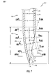
図6及び7を参照すると、針204の遠位端242は遠位面247を含むことができ、これは、様々な実施形態において、代替としてカット面、研削面、又は傾斜面と呼ぶことができる。いくつかの実施形態において、遠位面247は、針204の長手方向中心軸ALに対してある角度をなす斜面として形成され、それは挿入事象中の針204の回転軸に対応することができる。例えば、図示の実施形態において、遠位面247は実質的に平坦な斜面を画定している。傾面の面は図7のPとして識別される。傾斜した遠位面247は、研削などの任意の適切な方法で形成することができる。例えば、実質的に平面である遠位面247は、バイアスグラインド(これは単純バイアスグラインドとも呼ぶことができる)によって形成することができる。以下にさらに説明するように、いくつかの実施形態において、研削遠位面247は、実質的に円筒形のチューブの遠位端に形成され(例えば、研削され)、チューブは遠位面247が形成された後に曲げられる。他の実施形態において、遠位面247が形成される前に円筒形チューブが曲げられる。
Referring to FIGS. 6 and 7, the
図7を参照すると、図示の遠位面247は長手方向中心軸ALに対して角度αをなしている。角度αの任意の適切な値も考えられる。例えば、様々な実施形態において、角度αは約8度から約20度までの範囲内であり、約8、10、15、又は20度以上であり、あるいは約8、9、10、15、又は20度以下である。いくつかの実施形態において、角度αは、およそ11度である。
Referring to FIG. 7, the illustrated
図11Aに示すように、図示の実施形態において、オブチュレータ104が針204内に完全に挿入されるとき、その遠位面147は遠位面247に対してわずかに凹んでいる。遠位面147は、針204の遠位面247に実質的に平行であり得るか、又は遠位面247に対して小さい角度で配向され得、この角度は約1、2、3、4、5、又は10度以下の値を有する。さらに、オブチュレータ104及び針204のそれぞれの長手方向中心軸は、整列又は同一直線上にあり得るし、アクセスシステム又はアクセスアセンブリ109の長手方向中心軸AL-SYSにも対応し得るし、これはまたアクセスアセンブリ109の回転軸であり得る。いくつかの実施形態において、遠位面147は、長手方向中心軸に対して約8、9、10、15、又は20度以下の角度を画定し得る。いくつかの実施形態において、針204の遠位面247によって画定される角度αがおよそ11度である特定の実施形態のように、オブチュレータ104の遠位面147によって画定される角度はおよそ9.5度である。
As shown in FIG. 11A, in the illustrated embodiment, when the
図7及び9を参照すると、針204の遠位端242は、遠位面247のエッジに接合することができ、遠位端242の周囲の周りにそこから離れるように延びることができる湾曲又は丸みを帯びた領域248を含むことができる。針204の長手方向軸ALを通り、かつ遠位面247によって画定される平面P(すなわち、図7のページの平面)に対して垂直である平面において、遠位先端246における、又はそれに隣接する丸みを帯びた領域248に対する接線TANは、長手方向軸ALに対して角度βを画定することができる。角度βの任意の適切な値も考えられる。ある場合に、角度βは、角度αとほぼ同じであるか、それよりわずかに大きい。一緒に、角度α及びβは、皮膚を通して容易にスライスすることができる鋭い遠位先端246を提供するために十分に小さくあり得る。例えば、様々な実施形態において、角度βは約8度から約25度までの範囲内であり、約8、10、15、20、又は25度以上であり、あるいは約8、9、10、15、20、又は25度以下である。いくつかの実施形態において、角度βはおよそ15度である。様々な実施形態において、組み合わされた角度α及びβ(又は別の言い方をすると、遠位先端246のスライス角度)は、15、20、25、30、35、又は40度以下である。
Referring to FIGS. 7 and 9, the
針204が遠位方向に前進すると、遠位面247及び丸みを帯びた領域248によって画定されるような鋭い遠位先端246は、針204の遠位端242が組織を容易に穿通又はカットすることを可能にし得る。例えば、ある場合に、針204の遠位端242は、軸AL、AL-SYSの周りを回転させることなく、実質的に遠位方向に前進させることができ、メスと同様の方法などで組織をスライスすることができる。遠位先端246は、最終的に骨と接触するようになり得、その時点で針204は骨をカットするために回転され得る。
As the
図6及び7を再び参照すると、図示の実施形態において、針204は、その近位端でハブ203にしっかりと固定されているシャフト250を含む。シャフト250は遠位に延び、針204の遠位端242が始まるところで終わる。図示の実施形態において、シャフト250の遠位端と、針の遠位端242の近位端との間の境界は、図7の水平方向の破線で示されている。針204の遠位端242は、この境界から下方に延びて遠位先端246で終わっている。図5に示すように、シャフト250の外面は、任意の適切な種類の一つ又は複数の深度マーカー258を含み得る。
Referring again to FIGS. 6 and 7, in the illustrated embodiment, the
図示の実施形態において、針シャフト250は、その内面及び外面のそれぞれにおいて実質的に円筒形である。針シャフト250はまた、それぞれがシャフト250の長手方向の全長に沿って一定の直径を有する円形の横方向の内側及び外側の断面(横断面とも呼ぶことができる)を画定するとも言える。他の構成もまた考えられる。例えば、いくつかの実施形態において、シャフト250は、実質的に円錐台状として形成されてもよく、その内側又は外側の円形断面のうちの一つ又は複数の直径が遠位方向に減少するように、非常に緩やかなテーパを有してもよい。しかしながら、ある場合に、針シャフト250が実質的に円筒形の外面を有することが望ましい場合があり、これは移植後の針204の骨からの後退を抑制又は防止することができ、同様に挿入部位での溢出を抑制又は防止することができる。
In the illustrated embodiment, the
図示の実施形態において、針204の遠位端242は、その全長に沿って、長手方向軸ALに対して一定の横方向外側断面領域を画定していない。例えば、図7に見られるように、丸みを帯びた領域248及び遠位面247は、遠位先端246に向かって先細りになっている。針先端246は、針204の長手方向中心軸ALに向かって曲げられていると言ってもよい。丸みを帯びた領域248の輪郭が遠位方向に進むにつれて、その輪郭は針204の長手方向中心軸ALの近くに連続的に近づく。以下にさらに説明するように、図示の実施形態に示すように、遠位先端246を針204の長手方向中心軸AL上又はその近くに配置することができる。
In the illustrated embodiment, the
しかしながら、図示の実施形態において、針204の遠位端242は、遠位端242のかなりの長さに沿って内腔251の中心を通る中心線Cに対して、一定の又は実質的に一定の横方向内側断面領域を画定する。内腔251は、針204の内面252によって画定され、中心線Cは、内面252によって画定され、平面の全周の周りに直角に内面252と接触する各平面の中心を通って延びる線として定義することができる。この定義によれば、中心線Cは、それを通る横断面が内腔251の遠位開口部260の上端部と接触するときに終わる。すなわち、図7において、中心線Cの前述の定義によれば、中心線Cは、8C-8C線によって画定される断面の位置で終わる。これは、この点より下では、開口部260が存在するために、内面252と直角に接触する平面が内面252によって完全に画定されていないためである。
However, in the illustrated embodiment, the
さらなる実施形態において、図7、8D、及び8EにおいてPROJINとラベル付けされた破線によって示されるように、内面252は、針204の遠位開口部260を通って外向きに突出し得る。ある場合に、針204が形成された方法に応じて、この突出面は、針204の遠位端242の形成中に削り取られたチューブ状要素の一部の内面に対応し得る。ある場合に、中心線Cは、内面252及び突出部PROJINの一方又は両方によって画定され、平面の全周の周りで直角に内面252及び突出部PROJINの一方又は両方と接触する各平面の中心を通って延びる線として画定することができる。図示の実施形態において、図7及び8A~8Eに示すように、中心線Cに対して、内面252とその突出部PROJINの両方によって画定される横方向内側断面領域A(図8A~8E)は、遠位端242の全長に沿って実質的に一定であり得る。様々な実施形態において、中心線Cに対して(上記の中心線Cの定義の一方又は両方に従って)画定される横方向内側断面領域Aは、領域Aの最大値の5、10、15、20、25、30、35、40、45、又は50パーセント以下で針の全長に沿って変化する。
In a further embodiment, the
いくつかの実施形態において、針204の全長に沿って及び/又は針の長さに沿って遠位開口部260から近位方向に延びる比較的大きい又は妨げのない内腔251を有することが有利であり得る。例えば、ある場合に、そのような大きい又は遮られていない通路は、一般に、又はより具体的には補強材としての使用のために、オブチュレータ104の使用を容易にするか又は可能にし得る。他の又はさらなる例において、そのような通路は、内腔251を介した注入又は吸引のために比較的高い流量を可能にし得、又は他の例において、すでに制限、抑制、又は拘束され得るシステムに抵抗又は拘束の導入を回避できる。例えば、特定の緊急時のようないくつかの場合に、内腔251を介して薬物を罹患体の脈管に溶液で送達することが望ましくあり得、それは罹患体の骨への経路を提供する。そのような状況において、施術者は、薬物送達(例えば、IV)バッグを針204に連結し、そしてバッグを圧迫して溶液を罹患体の骨の中に押し込むことができる。骨及び/又はその内部構造及び/又はその中の自然の圧力は、このアプローチによって溶液を骨の中にどれだけ早く導入できるかを制限する可能性がある。従って、さもなければ部分的にブロックされた又は収縮された内腔251から生じ得るような、システムの任意のさらなる収縮を低減することが望ましいかもしれない。他の又はさらなる例において、罹患体への不快感を軽減するため、及び/又は処置後の皮膚及び骨組織の治癒を容易にするためなどに、針204が比較的小さい外径ODを有することが望ましい場合がある。しかしながら、なおさらなる用途において、針204は、挿入事象中にそれに与えられる静的及び慣性負荷に耐えるのに十分な柱状強度を有するために十分に大きいことが望ましい可能性がある。様々な実施形態において、針204に比較的大きい及び/又は比較的遮られていない内腔251を提供することは、針204の意図される用途に応じて、前述の目的のいくつか又は全てを達成させる又は釣り合わせることができる。
In some embodiments, it is advantageous to have a relatively large or
様々な実施形態において、針204のODは、17、16、15、14、又は13ゲージ以下(すなわち、ほどの大きさ)であり得る。別の言い方をすると、様々な実施形態において、針のODは、1000分の約58、65、72、83、又は95インチ(約1.5、1.7、1.8、2.1、又は2.4ミリメートル)以下であり得る。いくつかの実施形態において、ODは約15ゲージ(1000分の約72インチ、又は約1.8ミリメートル)である。他のサイズも可能である。例えば、ある場合に、前述のサイズは注入用途に有利であり得るが、特定の生検又は吸引用途にはより大きなサイズが望ましい場合がある。
In various embodiments, the OD of the
ちょうど検討したサイズ範囲内のODを有する様々な実施形態のような、特定の実施形態において、針204の側壁の厚さは、1000分の5、10、15、又は20インチ以下であり得る。ODが約15ゲージ(1000分の約72インチ)であるいくつかの実施形態において、壁厚は1000分の約10インチ以下であり得る。
In certain embodiments, such as various embodiments having an OD within the size range just considered, the thickness of the sidewall of the
ちょうど検討したサイズ範囲内のOD及び/又は壁厚を有する様々な実施形態などのような、特定の実施形態において、針204は、毎時約1リットルの流量(脛骨への注入の場合など)又は毎時約4リットルの流量(上腕骨への注入の場合など)を許容することができる。針204はさらに、IVバッグ等を圧迫する施術者からもたらされ得るような、多種多様な圧力にわたる前述の流量での流体送達に耐えることが可能であり得る。
In certain embodiments, such as various embodiments having OD and / or wall thickness within the size range just examined, the
図7、9A及び9Bを参照すると、前述したように、図示の実施形態において、シャフト250の外面は実質的に円筒形であるが、遠位端242の外面はそうではない。従って、針204は、シャフト250の長手方向の全長に沿って実質的に円形の(長手方向軸ALに対する)横方向外側断面を画定する(例えば、図8A参照)。さらに、実質的に円形の外側断面は、シャフト250の長手方向の全長に沿って実質的に一定である外径ODを画定する。いくつかの実施形態において、針204の遠位端242が、(回転軸に対応する)長手方向軸ALに対して、シャフト250の円形の横方向外側断面以下である横方向外側断面を有することが望ましい場合がある。例えば、図9A及び9Bに見られるように、端面図では実質的に円形である、シャフト250の円筒形の外面は、針204の遠位端242のどの部分によっても視界から遮られることはない。別の言い方をすると、シャフト250の外面は、側面方向又は横方向の周辺部253を画定することができ、いくつかの実施形態において、長手方向軸ALを通って直交して延びる任意の断面において実質的に同じであり、図示の実施形態において、横方向の周辺部253は実質的に円形である。本明細で使用されるとき、用語「実質的に円形」は、形状が一般に円形又は楕円形の輪郭を示し、その最大直径がその最小直径よりも10パーセント以下大きいことを意味する。図示の実施形態において、針204を回転させて、硬い骨を通るなどして穴を穿孔すると、シャフト250を穴の中にぴったりと嵌めることができる。
Referring to FIGS. 7, 9A and 9B, as described above, in the illustrated embodiment, the outer surface of the
シャフト250と針204の他の又はさらなる実施形態の遠位端242(又はカット部分)との間の関係は、他の用語で説明することができる。そのような針204はまた、シャフト250のぴったりの許容を可能にするような大きさの遠位端242を有する穴を作り出すことが可能であり得る。例えば、いくつかの実施形態において、遠位端242の長手方向の全長に沿って、遠位端242の各横方向(長手方向軸ALに対して)外側断面は、シャフト250の最小の横方向外側断面によって完全に又は部分的に囲まれ得る。他の又はさらなる実施形態において、遠位端242の各横方向外側断面の最大幅(例えば、直径)は、シャフト250の遠位端におけるような、シャフト250の最小外径寸法(例えば、外径)以下であり得る。特定の実施形態において、遠位端242の各横方向外側断面のどの部分も、シャフト250の少なくとも遠位部分の横方向の外側断面形状を越えて延びる(すなわち、横方向外向きに越えて延びる)ことはない。
The relationship between the
図示の実施形態のようないくつかの実施形態において、針204の長手方向の全長に沿ったどの位置においても、針の外面は、シャフト250の横方向外側断面の周辺部を越えて延びていないと言える。図示の実施形態のようないくつかの実施形態において、針204の遠位端242の長手方向の全長に沿ったどの位置においても、遠位端242の外面は、シャフト250の横方向外側断面の周辺部を越えて横方向外側に延びていないと言える。別の言い方をすると、針204の遠位端242の長手方向の全長に沿ったあらゆる位置において、遠位端242の外面は、シャフト250の外面の側面方向又は横方向の周辺部253、例えば、長手方向軸ALに直交する平面に沿ったシャフト250の最遠位端の周辺部よりもさらに長くなく、長手方向軸ALに対して横方向外側に延びる(図9A及び9B参照)。
In some embodiments, such as the illustrated embodiment, the outer surface of the needle does not extend beyond the periphery of the lateral outer cross section of the
特定の実施形態において、針204の遠位端242は、内腔251の中心及び/又はその突出部PROJINを通る中心線Cに対して一定の、又は実質的に一定の横方向外側断面領域を画定し得る。さらなる実施形態において、図7、8D、及び8EにおいてPROJOUTとラベル付けされた破線によって示されるように、針204の外面を内側突出部PROJINと同様の方法で突き出し得る。ある場合に、針204が形成された方法に応じて、この突出した外面は、針204の遠位端242の形成中に削り取られたチューブ状の要素の一部の外面に対応することができる。図示の実施形態において、中心線Cに対して、外面とその突出部PROJOUTの両方によって画定される横方向外側断面領域(図8A~8E)は、図7及び8A~8Eに示すように、遠位端242の全長に沿って実質的に一定であり得る。様々な実施形態において、(上に提供された中心線Cの定義のいずれか又は両方に従って)中心線Cに対して定義される横方向外側断面領域は、針の全長に沿ってその最大値の5、10、15、20、25、30、35、40、45、又は50パーセント以下だけ変化する。
In certain embodiments, the
同様に、図8A~8Eに示すように、外径ODは実質的に中心線Cに沿っていてもよい。様々な実施形態において、外径ODは、針の全長に沿ってその最大値の5、10、15、20、25、30、35、40、45、又は50以下だけ変化し得る。 Similarly, as shown in FIGS. 8A-8E, the outer diameter OD may be substantially along the center line C. In various embodiments, the outer diameter OD can vary by less than or equal to its maximum value of 5, 10, 15, 20, 25, 30, 35, 40, 45, or 50 along the overall length of the needle.
図8A~8Eを続けて参照すると、図7の中心線Cに対する一連の外側横方向断面外周部261A~261Eが示されている。これらの画像では、各断面における針204の最外周部261A~261Eは、実質的に円形(図8A~8C)又は実質的に半円形(図8D及び8E)に見える。しかしながら、様々な実施形態において、遠位端242の外周261B~261Eのうちの一つ又は複数の少なくとも一部は、完全な円形又は完全な半円形からわずかに変形している。例えば、以下にさらに説明するように、ある場合に、遠位端242の形成は、その部分がシャフト250の外周部261Aを越えて(長手方向軸ALに対して)横方向外側に延びないことを確実にするために、遠位端242を締め付け、圧着、圧縮、さもなければ拘束又は成形することを含み得る。このプロセスは、針204の遠位端242の外面及び/又は内面の少なくとも一部を変形して、中心線Cを横切る断面平面内で真円又は真半円を画定することがわずかに逸脱することがある。
With reference to FIGS. 8A-8E in succession, a series of outer lateral cross-sectional outer
図8A~8Eを続けて参照すると、針204の内面252に関して、中心線C(図7参照)に対する横方向内周は、実質的に円形又は実質的に半円形であり得る。例えば、図8A、8B、及び8Cのそれぞれにおいて、互いに直交する二方向の内径は、互いに実質的に等しい。すなわち、図8A、8B、及び8Cに示される内径は、全て実質的に等しいので、それぞれID1として識別される。しかしながら、いくつかの実施形態において、遠位端242の形成中のチューブのわずかな変形のために、直径(例えば、例示の図の垂直方向の直径)のうちの一つは、図8B又は8Cのうちの一つ又は複数において他の直径(例えば、例示の図の水平方向の直径)よりもわずかに小さくてもよい。それにもかかわらず、断面形状は実質的に円形のままであり得る。
With reference to FIGS. 8A-8E in succession, with respect to the
同様に、図8D及び8Eにおいて、表面252の内周が針204の遠位面247によって画定されている場合、一次元における内周の内径は、針204のより近位に位置する領域と実質的に同じであり得る。例えば、図8D及び8Eのそれぞれについての例示の図において垂直方向の直径は、ID1として識別される。しかしながら、いくつかの実施形態において、例示された図において、これらの垂直方向の直径は、遠位端242の形成中のチューブのわずかな変形のために、図8B又は8Cのうちの一つ又は複数の位置におけるような、遠位端242のより近位部分の同方向直径よりわずかに小さくあり得る。それにもかかわらず、断面形状は実質的に半円形のままであり得る。
Similarly, in FIGS. 8D and 8E, when the inner circumference of the
いくつかの実施形態において、上述のように、針204の実質的に円形の幾何学的形状は、針204が挿入事象中に骨に押し付けられ、及び/又は高速で回転するときに、遠位端242の座屈、曲げ、又は折り重ねに有利に耐えることができる。例えば、遠位端242、又はその任意の部分は、例えば、より薄い、より平らな、及び/又はより楕円形の外形を有することができる特定の構成と比較して、上述の幾何学的形状のために座屈、曲げ、又は折り重ねがはるかに起こりにくい傾向がある。これは、例えば、オイラーの臨界荷重式を適用することで証明でき、この場合、柱が担うことができる限界荷重は、柱の断面の最小面積慣性モーメントに正比例する。与えられた柱の最大外径に対して、この場合、針204の遠位端242は、単独で考えられるか、又はシャフト250の少なくとも一部と集合的に考えられるかのいずれかであり、円形の幾何学的形状に対する面積慣性モーメントの対称性のために、より薄い、より平らな、及び/又はより楕円形の輪郭と比較して、円形形状は座屈しにくい傾向がある。従って、例えば、図9Aを参照すると、上述した実質的に円形の幾何学的形状のために、遠位端242は、x軸周りと同様に、y軸周りの座屈に対してほぼ同じ抵抗を有することができる。
In some embodiments, as described above, the substantially circular geometry of the
図7を再び参照すると、遠位面247は長手方向の高さHを画定することができ、これは面247の最大長さの長手方向成分であり得、あるいは別の言い方をすると、面247が長手方向に延びる距離である。様々な実施形態において、長手方向の高さHは、約0.1、0.15、0.2、0.25、又は0.3インチであり、約0.1、0.15、0.2、0.25、又は0.3インチ以下であり、あるいは約0.1、0.15、0.2、0.25、又は0.3インチ以上である。任意の他の適切な高さも可能である。
Referring again to FIG. 7, the
遠位面247の長手方向の高さHは、遠位端242の長手方向の全長Lのかなりの割合であり得る。様々な実施形態において、遠位面247の長手方向の高さHは、遠位端242の長手方向の長さLの約50、60、70、80、又は90パーセント以上であり得る。いくつかの実施形態において、遠位面247の長手方向の高さHは、遠位端242の長手方向の長さLと実質的に等しくてもよい。
The longitudinal height H of the
丸みを帯びた領域248は、遠位端242の長手方向の全長Lに沿って延びることができる。丸みを帯びた領域248の曲率半径は、比較的大きくすることができ、あるいは別の言い方をすると、長手方向軸ALに向かう遠位端242の外面の偏向は緩やかになり得る。そのような構成は、遠位先端246の鋭さに寄与し得、そして皮膚組織を通る針204の挿入を容易にし得る。他の又はさらなる例において、そのような構成は、針204の長手方向軸ALから中心線C(これは円形の幾何学的形状の中心を通る)のわずかな逸脱だけのために、曲げ、折り畳み、又は座屈に対して比較的耐性があり得る。例えば、施術者が自動ドライバー108を下方又は遠位に押すとき及び針の遠位先端246が骨を押すときに、静荷重を針204の軸ALに沿って加えることができる。針204の全長はこの荷重に耐え、この全長に沿って延びる、遠位端242で小さな逸脱のみがあるだけで安定した円形の幾何学的形状により、針204が(例えば、針204の中心、又は他の場所において)座屈することなく荷重に耐えることを可能にする。円形構成は、同様に、針204の高い回転速度から生じる慣性負荷に対して抵抗力があり得る。
The
様々な実施形態において、丸みを帯びた領域248の長さ(図示の実施形態ではLに等しい)は、シャフト250のODの約2、2.5、3、3.5又は4倍以上である。いくつかの実施形態において、ODは1000分のおよそ72インチであり、長さLは1000分の約212インチである。いくつかの実施形態において、丸みを帯びた領域248の曲率半径は実質的に一定であり、及び/又は丸みを帯びた領域248の曲率は、実質的に単調である(例えば、近位から遠位方向に長手方向軸ALに向かってのみ進行するか、又は接近するのみで進行する)。様々な実施形態において、丸みを帯びた領域248の長さLは、針204の全長の4、5、6、7、8、9、又は10倍以上であり得る。
In various embodiments, the length of the rounded region 248 (equal to L in the illustrated embodiment) is about 2, 2.5, 3, 3.5 or 4 times or more the OD of the
図10を参照すると、針204の遠位端242は、カッティング端又はカッティング領域270を含み得る。カッティング領域270は、カッティングエッジ271及びカッティング面272を含み得る。図示の実施形態において、カッティングエッジ271は、針204の一方の側面からその反対側まで延びる連続に丸みを帯びたエッジである。カッティングエッジ271の二つの対向する上端部は、シャフト250の外径ODに等しい距離だけ互いに離間している。別の言い方をすると、カッティングエッジ271は、針204のODの一方側からODの反対側まで延びる。カッティング面272は、骨を通るカット及び/又はカットした骨物質の移動に寄与し得る遠位面247の下部であり得る。ある場合に、カッティング面272は、その外径が針204のODに対応する位置で終わっている。
Referring to FIG. 10, the
カッティングエッジ271は、遠位先端246を含むことができ、これはカッティングエッジ271の一番下に配置することができる。図示の実施形態において、遠位先端246はカッティングエッジ271上及び長手方向軸AL上に配置されている。従って、カッティング領域270は、罹患体の骨への刺入中に、長手方向軸ALの周り、又は遠位端246の周りを回転することができる。ある場合に、ドライバー101(図1参照)は、挿入事象中にカッティング領域270の半分だけが骨をカッティングすることができるように、針204を単一の方向に回転させることができる。例えば、図示の実施形態において、上から見て針を時計回りに回転させる場合、長手方向軸ALの右側にあるカッティング領域270の部分はカッティングに寄与するが、左側の部分はそうではなく、逆に、針を反時計回りに回転させると、その反対が当てはまる。ある場合に、針204は、自動ドライバー108の特定の実施形態を介するなどして、刺入中に一方向のみに回転されてもよい。
The
他の構成において、針204をそれぞれ向かい合った第1及び第2方向に前後に回転させることができ、カッティング領域270の両方の部分が骨のカッティングに寄与することができる。別の言い方をすると、針204は前後に、又は反対方向に回転させることができ、各ストロークで骨に切り込むこができる。すなわち、針204は、反対方向を向いたストロークでカットすることができ、さらなる実施形態において、反対方向を向いた各ストロークで同様に等しくカットすることができる。さらに別の言い方をすると、針204は双方向でカットすることができる。ある場合に、そのような前後のカッティング動作は、ドライバー101が手動操作可能なハンドルであるときなど、針204の手動操作中に利用され得る。
In other configurations, the
図10に示すような特定の実施形態において、カッティングエッジ271に沿った各点における接線の勾配は、カッティングエッジ271の一端からその反対側の端へ滑らかに移行する。別の言い方をすると、いくつかの実施形態において、カッティングエッジ271は、鋭いエッジ又は角がない、あるいは別の言い方をすると、接線の勾配が不連続部のない滑らかな丸みを帯びた表面であり得る。これは一般に当てはまる場合があり、又はいくつかの実施形態において、遠位先端246を含む領域内などで、カッティングエッジ271の中央部分にわたって、具体的にのみ局所的に当てはまる場合がある。例えば、遠位先端246で鋭い点に到達するのではなく、カッティングエッジ271は丸みを帯びた又は滑らかな曲線であり得る。
In a particular embodiment as shown in FIG. 10, the tangential slope at each point along the
図示の実施形態において、遠位先端246におけるカッティングエッジ271に対する接線Tは、長手方向軸ALに対して実質的に直交している。別の言い方をすると、接線Tは、両方とも遠位先端246を通過し、長手方向軸ALに対して90度の角度にある直交線Oと同一直線上にある。他の実施形態において、遠位先端246の接線Tは、直交線Oに対して約10、15、30、又は45度以下の角度を画定する。
In the illustrated embodiment, the tangent T to the
ある場合に、遠位先端246の接線Tと直交線Oとの間に角度がほとんど又は全くないこと、さらに接線Tの勾配が連続的であること、又は遠位先端246の一方側から他方側へ滑らかに移行することが望ましい場合がある。特定の実施形態において、そのような構成は、遠位先端246の近くに幅広いカッティング領域270をもたらし得る。別の言い方をすると、そのような構成は、直交線Oにも近い、又は別の言い方をすると、長手方向で遠位先端246に比較的近い(すなわち、軸方向に近い)とも言える丸みを帯びたカッティングエッジ271及びカッティング面272をもたらすことができる。従って、遠位先端246のいずれかの側のこれらの表面は骨に対して並進移動できるので、針204が遠位先端246の周りを回転するにつれて、カッティングエッジ271及びカッティング面272はより容易に骨をカットすることができる。ある場合に、針204が遠位に進められるにつれて、骨物質の層を削り取る、又は骨を穿孔する骨表面に対して、主に又は排他的に、カッティングエッジ271及びカッティング面272の並進移動である。従って、ある場合に、遠位先端246の近傍において、カッティングエッジ271が幅広であるか、又は長手方向軸ALから離れるように外向きに延びることが望ましい場合がある。
In some cases, there is little or no angle between the tangent T of the
いくつかの実施形態において、幅広い、外側に延びるカッティングエッジ271は、鋭く尖っている、又は別の言い方をすると、接線Tの勾配が不連続であり、遠位先端246において低い負の値から高い正の値へ急激にシフトするために、遠位先端246よりも良好に又はより滑らかにカットすることができる。例えば、いくつかの鋭く尖った遠位先端246は、15又は30度以下の角度を画定し得る。いくつかの実施形態において、遠位先端246が一点に達することがある(例えば、接線Tがそこで不連続になり、即座に負の値から正の値に変化することがある)が、その点によって画定される角度は、カットを容易にするために比較的大きくてもよく、例えば、約45、60、75、90、又は105度以上であってもよい。
In some embodiments, the wide, outwardly extending
いくつかの実施形態において、カッティングエッジ271は長手方向軸ALについて対称である。ある場合に、そのような構成は、刺入中の針204のぐらつきを抑制することができる。
In some embodiments, the
図示の実施形態のようないくつかの実施形態において、針204のみが挿入事象中に骨をカットする任意の表面を画定する。例えば、図11Aを再び参照すると、図示の実施形態において、オブチュレータ104は、針204の遠位面247に対して完全に凹んでおり、従って、オブチュレータ104は、アセンブリ109が穿通のために回転したときに骨をカットしない。従って、図10を再び参照すると、針204のみのカッティングエッジ271の物理的外形は、穿通事象に対する力印加プロファイルの滑らかさを制御し得、又は影響を及ぼし得る。例えば、図示の実施形態において、カッティングエッジ271の物理的外形は、(接線Tが実質的に水平である)遠位先端246から(いずれかの側の接線Tが実質的に垂直である)シャフト250の外面に近位に移行するにつれて滑らかで連続的である。実質的に長手方向軸ALに沿って遠位方向に向けられた力プロファイルは、同様に滑らかであってもよく、あるいは別の言い方をすると、急激な変化がなくてもよい。
In some embodiments, such as the illustrated embodiment, only the
例えば、ある場合に、オペレータは挿入事象のために自動ドライバー108を使用することができる。オペレータは、自動ドライバー108を作動させる前に、骨を針204の遠位先端246と接触させることができる。ドライバー108を作動させて針204を回転させると、オペレータは、針204を少なくとも骨の外面を通して遠位方向に前進させる傾向がある力をドライバー108に加えることができる。オペレータによって加えられる力は、実質的に一定であってもよく、あるいはカッティングエッジ271の連続的な性質のために穿通事象を通して大量から少量へ及び/又は少量から大量へと滑らかに移行してもよい。例えば、針204の外面に沿って不連続部がないため(さもなければ、例えば、針のカッティング面からオブチュレータのカッティング面への移行で起こり得るように)、同様に、穿通事象中にオペレータが加える力の量に不連続なジャンプがないかもしれない。
For example, in some cases, the operator may use the
図7を再び参照すると、針先端246は、それが針204の長手方向中心軸ALにごく近接して配置されるように形成される。例えば、図示の実施形態において、針先端246は長手方向中心軸AL上に直接配置されている。他の実施形態において、針先端246は、針204の最大横寸法(例えば、最大外径)の5、10、20、又は25パーセント以下の距離だけ長手方向軸ALから横方向に離間していてもよい。
Referring again to FIG. 7, the
特定の実施形態において、針204の遠位端242は、Tuohy、Huber、又は曲がった先端を有する他の針などのいくつかの標準的な種類の針とは異なる。そのような針は、上述したものと同様に、それらの遠位端に丸みを帯びた領域及び/又は一つ又は複数の傾斜したエッジを含むことができるが、それらの遠位先端は一般に長手方向中心軸に近接していない。特定の実施形態において、針204の遠位端242は、ランセット、レ形、又は湾曲していない先端を有する他の針を含む標準静脈針のような他の標準品種の針と同様に異なる。そのような針の遠位先端も同様に、一般に長手方向中心軸にごく接近していない。従って、この種の特定の針は、回転中(例えば、穿通中)に表面に対してぐらつくことがある。そのようなぐらつきは、例えば、硬い骨構造を通る穿通を複雑にする可能性がある。
In certain embodiments, the
さらに、Huber、Tuohy、及び/又は曲がった先端を有する他の種類の針は、成形作業中に先端で非円形(例えば、針の側壁の曲率に沿う長手方向軸に沿った横断面が非円形)になるか、又はさもなければ針のシャフト部分によって画定される外周を越えて横方向外向きに延びる領域を有する。ある場合に、これらの変形及び/又は拡大された領域は、針のシャフトよりも大きいアクセス穴の形成をもたらし得、それはシャフトが穴内にゆるく配置されることをもたらし得る。 In addition, Huber, Tuohy, and / or other types of needles with curved tips are non-circular at the tip (eg, non-circular cross-section along the longitudinal axis along the curvature of the needle sidewall) during the molding operation. ), Or has a region extending laterally outward beyond the perimeter defined by the shaft portion of the needle. In some cases, these deformed and / or enlarged areas can result in the formation of access holes larger than the shaft of the needle, which can result in the shaft being loosely placed in the hole.
図10を再び参照すると、いくつかの実施形態において、遠位面247は複数の小平面を含むことができる。例えば、いくつかの実施形態において、ランセットグラインドをバイアス斜面に適用してランセット点を得ることができる。このような実施形態のいくつかにおいて、遠位面247は三つの小平面を含むことができ、それはある場合に、三つの異なる平面を画定することができる。遠位面247のための任意の他の適切な構成も考えられる。
Referring again to FIG. 10, in some embodiments, the
前述のように、しかしながら、図示の実施形態は、硬い骨表面に到達するために重なっている皮膚組織に貫入するのに特によく適している。さらに、図示の針204の回転は、針のカッティング面を非常に効果的な方法で硬い骨を通って骨髄まで貫入させる。骨髄へのアクセスが達成されると、オブチュレータ104を取り外して、骨構造の内部と適切な医療デバイス又はシステム(例えば、流体ライン、シリンジ)との間の外部連絡を可能にすることができる。
As mentioned above, however, the illustrated embodiment is particularly well suited to penetrate the overlapping skin tissue to reach the hard bone surface. In addition, the rotation of the illustrated
図11Aは、骨内アクセスシステム100を使用する例示的な方法の初期段階を示し、組み立てられた状態のアクセスアセンブリ109の横断面図である。前述のように、アクセスアセンブリ109は、オブチュレータアセンブリ102、シールド105、及び針アセンブリ202を含む。ある場合に、アクセスアセンブリ109は事前に組み立てられており、従って実質的に図11Aに示す構成で任意の適切な無菌包装から取り出すことができる。ある場合に、キャップ107(図1参照)を最初にアセンブリ102の遠位端から取り外して、図示の構成に到達させることができる。
FIG. 11A shows an early stage of an exemplary method using the
図示の組み立てられた状態において、オブチュレータハブ103及び針ハブ203のそれぞれのキー付き連結インターフェース137、210は、オブチュレータ104と針204との間の所定の関係が確実に達成されるように協働することができる。別の言い方をすると、キー付き連結インターフェース137、210は、オブチュレータ104が針204に対して一定の角度方向を画定することを確実にすることができる。連結インターフェース137、210は、挿入事象中、例えば自動ドライバー108を介したアクセスアセンブリ109の回転中に、アクセスアセンブリ109の回転中も同様に一定の角度方向を維持し得る。
In the illustrated assembled state, the keyed articulated
図示の実施形態において、オブチュレータ104の遠位面147は、針204の遠位面247に対してわずかに凹んでいる。さらに、図示の実施形態において、オブチュレータ104及び針204のそれぞれの遠位面147、247は、互いに実質的に平行である。いくつかの実施形態において、オブチュレータ104は、挿入事象中に皮膚又は骨のいずれかを通ってカットしない。他の実施形態において、遠位面147、247は互いに実質的に面一であってもよい。オブチュレータ104は、針204の内腔251内への通路を実質的に満たすか、又はさもなければ遮断することができる。例えば、図示の実施形態において、オブチュレータ104の遠位面147は、内腔251の遠位端への開口部と実質的に同じサイズである。様々な実施形態において、オブチュレータ104の遠位面147の面積は、針204の遠位面247の内側エッジによって画定される面積よりも5、10、15、又は20パーセント以下小さい。オブチュレータ104は、組織及び/又は骨物質が、針204の内腔251内に進入及び/又は前進するのを抑制又は防止することができる。
In the illustrated embodiment, the
針204の内面253及びオブチュレータ120の外面は、組織、骨、及び/又は他の物質の進入を防止又は抑制するように相補的に成形する及び/又は別の方法で構成することができる。さらなる実施形態において、オブチュレータ120と針204との間の嵌合は、オブチュレータ120を針204から容易に取り外すことを可能にし得る。例えば、ぴったり合うもの、ゆったりと合うもの、又は最小の間隙が、オブチュレータ120と針204との間の少なくとも一部分の間に設けられてもよい。
The
図11Aを続けて参照すると、アクセスアセンブリ109の組み立て中に、オブチュレータハブ103のアーム又は突出部132を、針ハブ203のスカート228を越えて前進させることができる。突出部132のスナップインターフェース又は内側突出部134は、オブチュレータハブ103及び針ハブ203を連結状態に維持するためにスカート228の下側を掴むことができる。図示の実施形態において、スカート228は、実質的に外向きの突出部として形成されており、アーム132の内面はその中に突出部が受け入れられる凹部を実質的に画定している。他の実施形態において、突出部/凹部インターフェースを逆にすることができる。例えば、アーム132は、オブチュレータハブ103を針ハブ203と連結するために、突出部がスカート228によって画定される凹部内に受け入れられるように画定することができる。
With reference to FIG. 11A in succession, the arm or
突出部132及びスカート228は、まとめて解放可能な係合機構262と呼ぶことができる。解放可能な係合機構262は、アクセスアセンブリ109の一般的な操作中、例えばパッケージからの取り出し中及び/又は自動ドライバー108との連結中などに、オブチュレータハブ103と針ハブ203とをともに連結したままにするように構成され得る。しかしながら、解放可能な係合機構262は、針ハブ203に対して近位方向にオブチュレータハブ103に十分な除去力を加えると解放されることが可能である比較的弱い連結を提供し得る。例えば、解放可能な係合機構262は、オブチュレータハブ103を針ハブ203と係合させ続ける傾向がある連結力を提供することができる。オブチュレータハブ103に対する近位方向の力が解放可能な係合機構262の連結力を超えると、解放可能な係合機構262は解放され、オブチュレータハブ103を針ハブ203から引き抜くことを可能にすることができる。様々な実施形態において、連結力(すなわち、オブチュレータハブ103上の近位方向の力に対抗する力)は、約0.25、0.5、0.75、1.0、1.5、又は2.0ポンド以下であり得る。
The
特定の実施形態において、解放可能な係合機構262は、針204と針204が挿入される骨との間の埋め込み力よりも有意に低い連結力を提供する。別の言い方をすると、解放可能な係合機構262は、カニューレ204を骨内に配置した状態に維持する骨によってカニューレ204に付与される力よりも強度が小さい近位方向の力をオブチュレータハブ103に付与することによって、針ハブ203が骨内に導入された後、オブチュレータハブ103を針ハブ203から切り離すことができるように構成することができる。
In certain embodiments, the
従って、いくつかの実施形態において、アクセスアセンブリ109を骨に導入した後、ユーザは、解放可能な係合機構262の連結力を超える任意の量の力でオブチュレータハブ103上において単に又は近位方向に引き戻すことができ、オブチュレータハブ103は針ハブ203から自動的に外れる。さらに、オブチュレータハブ103を針ハブ203及び罹患体から引き抜くことができ、針204を骨内に維持することができる。ある場合に、ユーザは、アクセスアセンブリ109が骨内に導入された後に、片手を使用して針ハブ203からオブチュレータハブ103を取り外すことができる。解放可能な係合機構262の他の適切な構成も考えられる。
Thus, in some embodiments, after introducing the
図11Aを続けて参照すると、アクセスアセンブリ109は組み立てられた状態にあるとき、シールド105は、未ロック状態でオブチュレータ104及び針ハブ204のそれぞれと連結されることができ、その場合、アーム162、163は長手方向軸AL-SYSから外向きに離れるように偏向する。特に、オブチュレータ104の近位端140は、凹部150よりも大きい直径を画定することができ、シールド105の全体にわたって延在することができる。別の言い方をすると、オブチュレータ104の近位端140は、横方向延伸部172、173及びカラー160を通って延びる。以下にさらに説明するように、オブチュレータ104のこのより大きな直径領域は、ユーザがオブチュレータハブ103を針ハブ204から取り外そうとするときに、オブチュレータ104がシールド105に対して近位方向に並進することを可能にするようにシールド105を未ロック状態に維持することができる。
With reference to FIG. 11A in succession, when the
シールド105が未ロック状態にあるとき、アームは外側に偏向し、それはアーム162、163の外側突出部178、179をそれぞれ針ハブ203の溝227内に固定、又はさもなければ配置することができる。従って、外側突出部178、179は、シールド105を通るオブチュレータ104の引き抜きの初期段階中に、シールド105を針ハブ203に対して一定の長手方向位置に維持するために溝227と協働することができる。他の実施形態において、溝227と外側突出部178、179とは逆にすることができる。例えば、いくつかの実施形態において、針ハブ203の内面は一つ又はそれ以上の内側突出部を画定してもよく、アーム162、163は、シールド105が(オブチュレータ104に対して)未ロック状態にあり、かつ針ハブ203に対して連結状態にあるときに、内側突出部がその中に受け入れられる内側凹みを画定してもよい。アーム181、182(図11Aでは見えない;図4参照)も同様に、図11Aに示す構成において外側に偏向した状態に維持することができる。
When the
図11Aを続けて参照すると、使用前又は穿通状態とも呼ぶことができる組み立てられた状態にあるとき、シールド105は、アクセスアセンブリ109の長手方向軸AL-SYSに比較的近い薄型の構成を画定する。長手方向軸AL-SYSはまた、中心軸又は回転軸とも呼ぶことができる。すなわち、罹患体の骨へのアクセスアセンブリ109の遠位端の挿入の間、アクセスアセンブリ109は軸AL-SYSの周りに回転することができる。多くの場合、アクセスアセンブリ109が自動ドライバー108と連結されているときなど、回転は非常に速くなり得る。ある場合に、回転軸に近い薄型の構成を画定することによって、シールド105は、アクセスアセンブリ109が骨に挿入されると、シールド105が急速に速度を上げるために回転することを可能にする、及び/又はシールド105が急速に回転を停止することを可能にする低い回転慣性モーメントを有することができる。シールド105はまた、比較的軽量であり得、これは比較的低い回転慣性モーメントにも寄与し得る。
With reference to FIG. 11A in succession, the
図11Bは、骨内アクセスシステム100を使用する例示的な方法の別の段階を示す。図示の段階の前に、アクセスアセンブリ109は、自動ドライバー108などのドライバー101と連結することができる。アクセスアセンブリ109、又はより詳細には、連結状態にある針204及びオブチュレータ104の遠位端は、針204の遠位先端246が骨306の外面に接触するまで、罹患体302の皮膚304を通って遠位に前進する。前述のように、針204は、皮膚304を通ってスライスするのに特によく適し得る。ある場合に、アクセスアセンブリ109は実質的に回転することなく骨306に向かって遠位方向に前進する。従って、針204の遠位端は、それが骨306と接触するように進行するにつれて皮膚組織を通ってスライスして分離することができる。骨と接触すると。
FIG. 11B shows another step in an exemplary method using the
骨306と接触すると、オペレータは自動ドライバー108を作動させてアクセスアセンブリ109を急速に回転させることができる。図示の実施形態において、アクセスアセンブリ109は、上から見て時計回りの方向にのみ回転する。従って、カッティング領域270の強調表示された部分のみが骨306のカッティングに寄与し得る。オペレータは、自動ドライバー108に、従ってアクセスアセンブリ109に遠位方向の力を加えて、アクセスアセンブリ109を骨306の硬質層307を通って下にある骨髄308内に前進させる。他の方法において、アクセスアセンブリ109は、代わりに、皮膚304、次いで硬い骨307の両方を通って、回転することができる。いずれの場合も、アクセスアセンブリ109が骨306の内部に前進すると、穿通抵抗の急激な減少により、オペレータは触覚フィードバックから感知することができる。次いで、オペレータは自動ドライバー108の作動を停止し、自動ドライバー108をアクセスアセンブリ109から切り離すことができる。
Upon contact with the
図11Cは、例示的な方法の次の段階を示し、骨306の内部へのアクセスを提供するために使用された後のアクセスアセンブリ109の横断面図を示す。図11Cに示す段階の後、オブチュレータアセンブリ102を針アセンブリ202から取り外すことができる。図示の実施形態において、オブチュレータアセンブリ102は、それを近位方向に引っ張ることによって取り外すことができる。オブチュレータアセンブリ102の取り外しは、図11D及び11Eに関して以下でさらに説明される。
FIG. 11C shows the next step of the exemplary method and shows a cross-sectional view of the
図11Dは、図11Cに示された段階に続く例示的な方法の段階におけるアクセスアセンブリ109の一部の拡大横断面図である。明確にするために、オブチュレータハブ103は針ハブ203から引き抜かれ始めたばかりなのでオブチュレータハブ103は図示されていないが、図示された図には存在するであろう。特に、図示の段階において、オブチュレータアセンブリ102は、上向きの矢印で示すように、針アセンブリ202から分離され、引き抜かれている。
FIG. 11D is an enlarged cross-sectional view of a portion of the
シールド105は、図11A及び11Cに示すものと実質的に同じ向きに維持することができる。特に、シールド105は、アーム162、163の開口部174、175内にそれぞれ配置されたオブチュレータ104の部分の比較的大きい直径のために、未ロック状態のままであり得る。特に、オブチュレータ104は、開口部174、175のより大きく実質的に円形の部分を画定する横方向延伸部172、173の部分(図4参照)が、オブチュレータ104の外面に沿って並進するのに十分な大きさであり得る。別の言い方をすると、オブチュレータ104は、開口部174、175のより大きな、実質的に円形部分内でスライド又はさもなければ並進運動するのに十分に小さくてもよいが、開口部174、175の狭くて実質的に矩形部分に適合するには大きすぎてもよい(図4参照)。従って、開口部174、175を画定する横方向延伸部172、173の内面は、オブチュレータ104の外面を押圧して、アーム162、163を外側に偏向した又は変位した状態に維持することができる。この外向きの偏向は、針ハブ203の溝227内に外側突出部178、179を固定する。従って、シールド105は針ハブ203に連結されたままである。
The
オブチュレータ104の比較的大きな直径のため、オブチュレータ104が近位方向に引き込まれ続けるとき、シールド105は、オブチュレータ104の近位全長に沿って実質的に一定であり得るので、未ロック状態のままであり得る。オブチュレータ104は、アーム162、163を外側に偏向した又は変位した状態に維持することができる。この外向きの偏向は、針ハブ203の溝227内に外側突出部178、179を固定する。従って、シールド105は針ハブ203に連結されたままである。
Due to the relatively large diameter of the
図11Eは、オブチュレータ104が針ハブ203から完全に引き抜かれている例示的な方法の次の段階におけるアクセスアセンブリ109の別の拡大横断面図である。別の言い方をすると、オブチュレータアセンブリ102は、針アセンブリ202から完全に引き抜かれており、上向きの矢印で示すように、針アセンブリ202から離れる方向に移動し続ける。図示された段階の前に、オブチュレータ104は、凹部150を開口部174、175の近傍に持ってくるのに十分な量だけ近位に引き込まれる。凹部150の直径が小さいため、開口部174、175のくびれた部分は凹部150に適合しており、従ってアーム162、163は自動的にそれらの偏りない、偏向していない、又は変形していない状態に移行できる(又は他の実施形態において、これは偏りの少ない、偏向の少ない、又は変形の少ない状態であり得る)ことを可能にする。別の言い方をすると、アーム162、163は、シールド105をオブチュレータ104に自動的にロックするために、より曲げられていない又は曲がっていない状態に弾性的に戻ることができる。
FIG. 11E is another enlarged cross-sectional view of the
シールド105がロック状態にあるとき、開口部174、175のくびれた部分を画定する横方向延伸部172、173の部分は、シールド105をオブチュレータ104に固定するために凹部150内に入る。同様に、図示の実施形態において、オブチュレータ104のより大きな茎部によって以前に外側に偏向していたアーム181、182の端部(図4参照)も同様に、凹部150内に内側に偏向し得る。シールド105がオブチュレータ104にロックされると、オブチュレータ104に対するシールド105の移動を防止し、又は一つ又は複数の方向(例えば、長手方向に及び/又は回転方向に)限定することができる。いくつかの実施形態において、横方向延伸部172、173とそれぞれ凹部150の近位面及び遠位面との間の干渉は、オブチュレータ104に対するシールド105の長手方向の移動を画定することができる。さらなる例において、凹部150にも存在するアーム181、182の端部(図4参照)は、バックアップの安全対策として役立つことができ、オブチュレータに対して近位方向にシールド105に十分な力が加えられた場合、凹部150の近位面と係合してシールド105とオブチュレータ104との間の係合を維持し、凹部150から横方向延伸部172、173を取り外すことができる。横方向延伸部172、173が凹部150から取り外され、シールド105がわずかにさらに近位に移動すると、アーム181、182の近位端は、凹部150の近位面と係合して、オブチュレータ104に対するシールド105の任意のさらなる近位移動を防止する。
When the
図示の実施形態において、アーム162、163がオブチュレータ104に対して自動的にロック状態に移行すると、アーム162、163は実質的に同時にシールドを針ハブ203から分離する。特に、図示の実施形態において、アーム162、163の内側への移動により、外側突出部162、163が針ハブ203の溝227から出る。これにより、シールド105は、例えば内腔224から出るための、長手方向における近位方向への移動のために、針ハブ203に対して自由に動くことができる。シールド105は、オブチュレータ104に対して自然にロック状態のままであり、オブチュレータ104の遠位先端146へのアクセスを制限する。
In the illustrated embodiment, when the
図4を再び参照すると、前述のように、シールド105がオブチュレータ104にロックされたときに、遠位先端146へのアクセスを制限するために、シールド105は、オブチュレータ104の遠位先端146を実質的に取り囲むケージ又は囲い180を画定することができる。図示の実施形態において、シールド105のカラー160は、その遠位端に一定の開口部167を画定している。すなわち、シールド105が未ロック状態からロック状態に移行しても開口部167の形状は変化しない。限定された意味において、遠位先端166は、遠位先端146が開口部167を通して見ることができるという点で、オブチュレータ104の遠位先端146を覆わない。それにもかかわらず、シールド105は遠位先端146との不用意な接触を防止することができるので、シールド105は依然として遠位先端146を覆うと言える。例えば、開口部167は、施術者又は他の個人が開口部167を通して皮膚の任意の部分に挿入して先端146と接触するのを防止するのに十分に小さくあり得る。他の実施形態において、開口部167はより小さくてもよく、及び/又はシールド105がロック状態に移行したときに閉じるように構成されてもよい。例えば、いくつかの実施形態において、片持ちアーム、バルブ、エラストマー隔膜、又は他の自然閉鎖デバイスを開口部167に配置することができる。
Referring again to FIG. 4, as mentioned above, the
図12A及び12Bは、ドライバー401の別の実施形態の正面図及び斜視図をそれぞれ示す。図示の実施形態において、ドライバー401は、自動ドライバー108の代わりに使用することができ、さらにオブチュレータアセンブリ102の様々な構成要素を組み込んでいる手動ドライバー408である。他の実施形態において、手動ドライバー408は代わりに自動ドライバー108を単に置き換えてもよく、例えば、手動ドライバー408の遠位部分は、自動ドライバー108の接続インターフェース112のそれと類似の接続インターフェースを含んでもよく、それを介して手動ドライバー408をオブチュレータアセンブリ102に直接に接続することができる。図示の実施形態において、手動ドライバー408は、針アセンブリ202と連結するように構成され、針204を罹患体の骨に導入するために施術者の一つ又は複数の手によって操作され得る。
12A and 12B show a front view and a perspective view of another embodiment of the
手動ドライバー408は、長手方向に細長くすることができるハンドル410を含む。ハンドル410は、ハンドル410上のユーザの握りを向上させることができる複数の水平溝412などの任意の適切な把持機構411を含むことができる。ハンドル410の外面形状は、任意の適切な人間工学的構成を有し得る。
The
手動ドライバー408は、上述の同じ番号の連結部材131及び連結インターフェース137に似た一対の連結部材431及び連結インターフェース437を含むことができる。これらの機構は、手動ドライバー408を針アセンブリ202に連結するのと同様の方法で機能し得る。同様に、手動ドライバー408は、オブチュレータ104などのオブチュレータ404を含むことができる。
The
手動ドライバー408は、針アセンブリ202に連結することができ、骨内アクセスを提供するために使用することができる。図示の実施形態は、長手方向軸を中心にいずれかの方向に回転したときに骨をカットすることができる。ある場合に、施術者は、ハンドル410の近位端を下方に押すことができ、針を骨に挿入するためにハンドル410を前後に回転させることができる。
A
図13は、多くの点でシステム100に似た骨内アクセスシステム500の別の実施形態を概略的に示す。システム500は、コネクタ506にしっかりと固定された針504を有する針アセンブリ502を含む。システム500は、コネクタ516にしっかりと固定されたオブチュレータ514を含むオブチュレータアセンブリ512をさらに含む。アセンブリ502、512は、連結状態で示されている。アセンブリ502、512は、接続インターフェース520を介して連結される。コネクタ516は、骨内アクセスを得るためにシステム500を手動で操作するために使用することができるT字型グリップ530又はハンドルを画定している。
FIG. 13 schematically illustrates another embodiment of the
接続インターフェース520は、任意の適切な種類のものであり得る。以下にさらに説明するように、いくつかの実施形態において、オブチュレータアセンブリ512が取り外された後に、接続インターフェース520をさらに使用して、針504を任意の適切な医療インターフェースに接続することができる。例えば、インターフェース520は、オブチュレータアセンブリ512が取り外された後に、外部チューブ(例えば、IVライン)、吸引機器、及び/又は他の医療デバイスと連結され得る、ルアーフィッティングとして構成され得る。他の実施形態において、接続インターフェース520は、オブチュレータアセンブリ512への接続のために使用され得るし、追加の又は別個の接続インターフェースは、針アセンブリ502によって提供される骨内アクセスを利用する一つ又は複数の医療デバイスへの接続(例えば、その後の接続)のために使用され得る。さらに他の実施形態において、接続インターフェース520を一つ又は複数の医療デバイスへの接続のために使用することができ、追加の接続インターフェースをオブチュレータアセンブリ512への接続のために使用する。
The
コネクタ516は、オブチュレータ514の近位端にしっかりと固定されている。コネクタ516は、前述のように、針アセンブリ502のコネクタ506と選択的に連結するように構成することができる。例えば、いくつかの実施形態において、コネクタ506の接続インターフェース520は、ルアーフィッティングを含み得るし、オブチュレータアセンブリ512のコネクタ516は、それと連結するように構成された相補的ルアーフィッティング(図示せず)を含み得る。コネクタ506、516を連結するための任意の適切な接続インターフェースも考えられる。
The
図示の実施形態において、針アセンブリ502及びオブチュレータアセンブリ512が連結状態にあるとき、オブチュレータ514は、コネクタ506及び針504の内腔を通って延びる。特定の実施形態において、骨内アクセスが確立されると、針アセンブリ502は骨に留まり得る一方、コネクタ516はコネクタ506から分離され得るし、オブチュレータアセンブリ512は針アセンブリ502から取り外され得る。硬い骨組織に貫入するのに十分な並進及び/又は回転力を連結アセンブリ502、512に手動で加えることを可能にする、コネクタ516のための任意の適切な構成も考えられる。
In the illustrated embodiment, when the
図14は、ある点で、上記の骨内アクセスシステムに類似し得る骨内アクセスシステム600の別の実施形態を示す。システム600は、そのコネクタ616が、T字型構成ではなく、骨内アクセスを得るためにシステム600を手動で操作するために使用され得る手動突き上げハンドル630として形成され得ることを除いて、システム500と同一であり得る。コネクタ616の任意の適切な構成も考えられる。
FIG. 14 shows another embodiment of the
上述したような針を形成するために任意の適切な方法を使用することができる。拡大解釈すれば、そのような方法は、本明細書に記載のアクセスアセンブリ及び/又は骨内アクセスシステムのいずれかを製造するのに使用されるプロセスのサブセットを形成することができる。いくつかの実施形態において、針は円筒形チューブから形成される。チューブは、その全中心軸に沿って円形の横方向の周辺部、又は横断面を維持するように曲げられ、中心軸は前述のような方法でチューブの曲げに追従する。遠位先端の遠位面(例えば、遠位面247)は、研削などの任意の適切な技術によって形成することができる。 Any suitable method can be used to form the needle as described above. In broader interpretation, such methods can form a subset of the processes used to manufacture any of the access assemblies and / or intraosseous access systems described herein. In some embodiments, the needle is formed from a cylindrical tube. The tube is bent along its entire central axis to maintain a circular lateral periphery or cross section, the central axis following the bending of the tube in the manner described above. The distal surface of the distal tip (eg, distal surface 247) can be formed by any suitable technique such as grinding.
他の又はさらなる実施形態において、形成プロセスは、針の遠位端(例えば、遠位端242)は、針の遠位端から近位方向に延びるシャフト部分によって画定される横方向断面又は周辺部を越えて横方向外向きに延びない横方向断面など、前述の特性のうちの一つ又は複数を有するということを確かにする。例えば、いくつかの実施形態において、そこから針が形成されるチューブの外面は、少なくとも製造中に曲げが行われる領域に拘束される。拘束は、冶具などの任意の適切なアセンブリ構造によって提供されてもよい(例えば、図16に示す冶具800参照)。
In another or further embodiment, the forming process is that the distal end of the needle (eg, the distal end 242) is a transverse cross section or periphery defined by a shaft portion extending proximally from the distal end of the needle. It ensures that it has one or more of the above-mentioned properties, such as a lateral cross section that does not extend laterally outward beyond. For example, in some embodiments, the outer surface of the tube from which the needle is formed is constrained to at least the region where bending occurs during manufacturing. Restraint may be provided by any suitable assembly structure, such as a jig (see, eg,
いくつかの方法において、冶具は、研削の前に針が形成されているチューブを曲げるために使用され、次いで、次の工程で針の先端が研削される。他の方法において、冶具は、針の先端が研削によって形成された後に使用される。様々な実施形態において、針の遠位端は、アクセス事象中に針の遠位端によって形成される穴又は孔の直径がシャフトの外径と同じかそれよりも小さくなるように形成される。別の言い方をすると、針の遠位端によって形成される穴又は孔の周辺部は、シャフトの横方向の周辺部と同じかそれよりも小さくあり得る。 In some methods, the jig is used to bend the tube in which the needle is formed prior to grinding, then the tip of the needle is ground in the next step. In other methods, the jig is used after the tip of the needle has been formed by grinding. In various embodiments, the distal end of the needle is formed such that the diameter of the hole or hole formed by the distal end of the needle during an access event is equal to or smaller than the outer diameter of the shaft. In other words, the perimeter of the hole or hole formed by the distal end of the needle can be the same as or smaller than the lateral perimeter of the shaft.
図15A~15Eは、上述した針204などの針を形成する例示的な方法における様々な工程を示す。拡大解釈すれば、例示的な方法は、例えばアクセスアセンブリ109を製造するのに使用されるプロセスのサブセットを形成することができる。
15A-15E show various steps in an exemplary method of forming a needle, such as the
図15Aを参照すると、プロセスの初期段階において、チューブのストック供給材料を長さに切断してチューブ700を得る。ある場合に、ストックチューブは最初に湾曲を有するように巻かれる。従って、いくつかの実施形態において、チューブ700は、長さに切断される前又はされた後のいずれかに真っ直ぐにされる。チューブ700は、真っ直ぐにされた後には実質的に円筒形であり得る。別の言い方をすると、チューブ700の内面及び外面のそれぞれは、実質的に円筒形であり得る。チューブ700は、長手方向軸ALを画定することができ、チューブ700の横断面の周辺は、実質的に円形であり得る。
Referring to FIG. 15A, in the early stages of the process, the stock feed material of the tube is cut to length to obtain the
図15Bを参照すると、プロセスの別の段階において、チューブ700の遠位端を所望の量だけ曲げることができる。チューブ700を曲げると、実質的に円筒形のままであり得るシャフト702、及びシャフト702から遠位方向に延びる湾曲領域704をもたらすことができる。湾曲領域704は、チューブの湾曲領域704が長手方向軸ALと交差するようにチューブ700の十分な偏向によって形成することができる。
Referring to FIG. 15B, at another stage of the process, the distal end of the
図15Cを参照すると、プロセスの別の段階において、遠位面720を形成するために、湾曲領域704の一部を研削するか、又はさもなければ除去することができる。遠位面720は、上述した針204の遠位面247に対応することができる。ある場合に、遠位面720は、単純なバイアスグラインドとして形成することができる。チューブ700の遠位端を研削することにより、チューブの最遠位点725を得ることができる。例えば、曲げる前に(図15A)、チューブ700の遠位先端は、平面環状部などの面で終わってもよい。曲げた後(図15B)、チューブ700の最遠位部分は代わりに最遠位点723で終わってもよい。しかしながら、その段階では、最遠位点723は長手方向軸AL上に直接はない。研削後(図15C)、チューブ700は、現在、長手方向軸AL上にある異なる最遠位点725で終わってもよい。
Referring to FIG. 15C, at another stage of the process, a portion of the
図15Dを参照すると、チューブ700の曲げは、湾曲領域704の少なくとも一部に実質的に楕円形の輪郭を画定させることができる。外形は、チューブ700を通る中心軸ACに直交する平面に沿った横断面のチューブ700であり得る。図15Cにおいて、中心軸ACは、シャフト702全体にわたって長手方向軸ALと一直線上に並んでおり、図15Dの断面にも並んでいる。ある場合に、中心軸ACは、図15Bに示すように、湾曲領域704内の中心にくるように湾曲し得る。
Referring to FIG. 15D, bending of the
図15Dを続けて参照すると、楕円形の輪郭は、中心軸ACに実質的に直交する第1次元に細長くすることができる。図示の構成において、第1次元は横寸法である。 With reference to FIG. 15D in succession, the elliptical contour can be elongated in the first dimension substantially orthogonal to the central axis AC . In the illustrated configuration, the first dimension is the horizontal dimension.
図15Eを参照すると、例示的な方法の別の段階において、一つの圧縮力、又は複数の圧縮力を第1次元に沿ってチューブ704の湾曲領域704に加え、従って湾曲領域704を中心軸ACに向かって内側に付勢し得る。圧縮力は、内側方向の矢印として概略的に示されている。任意の適切な機器又は機械を、力を加えるために使用することができる。例えば、いくつかの実施形態において、力は万力又は他のデバイスによって加えられてもよい。万力は、(図15Fのように)湾曲領域704の少なくとも一部を円形にするために万力が所定の幅に締め付けられるようにマークを付けられてもよい。ある場合に、第1次元と中心軸ACとの両方に直交する第2次元に沿って湾曲領域704を伸長させながら、第1次元に沿って湾曲領域704の断面形状を狭くするように圧縮力が湾曲領域704に加えられる。図示の実施形態において、湾曲領域704は縦寸法において細長く、横寸法において狭くなっている。
Referring to FIG. 15E, in another step of the exemplary method, one compressive force, or multiple compressive forces, is applied to the
図15Fを参照すると、例示的な方法の別の段階において、圧縮力を除去することができ、又は湾曲領域704から除去することができる。別の言い方をすると、ある場合に、湾曲領域704が解放されてもよい。ある場合に、湾曲領域704を解放することによって、ある場合に、湾曲領域704を楕円形ではない方向に自然に跳ね返すことができ、それは実質的に円形であり得る。圧縮力を除去した後、湾曲領域704の全体を、シャフト702の外側円筒面の仮想突出部PROJ(図15C)によって取り囲むか、包囲するか、又はさもなければその中に収めることができる。仮想突出部PROJは、曲げる前の湾曲領域704の元の位置として考えられてもよく、又は長手方向軸ALに沿って中心に置かれたままである円筒面の連続として考えられてもよい。言い換えれば、圧縮が加えられた後、遠位領域704のいかなる部分も、シャフト702の外側円筒面の仮想突出部を越えて横方向外向きに延びることはない。
With reference to FIG. 15F, in another step of the exemplary method, the compressive force can be removed or removed from the
今説明した例示的な方法の様々な段階は、異なる順序で実行してもよく、及び/又は他の段階と同時に実行してもよい。例えば、ある場合に、曲げ段階を圧縮段階と同時に行ってもよい。ある場合に、研削を曲げの前に行ってもよい。例示的な方法の他の変更も考えられる。 The various steps of the exemplary method just described may be performed in different order and / or at the same time as the other steps. For example, in some cases, the bending step may be performed at the same time as the compression step. In some cases, grinding may be performed prior to bending. Other modifications of the exemplary method are conceivable.
上述したオブチュレータ104のようなオブチュレータを形成するいくつかの方法は、針204の形成に関して説明した例示的な方法と同じ又は実質的に同じであり得る。しかしながら、チューブを使用するよりも、方法はロッド又はワイヤを使用することができる。
Some methods of forming an obturator, such as the
図16は、その遠位端が前述の特性のうちの一つ又は複数を示すように、針の遠位端又はオブチュレータを形成するために使用することができる冶具800の斜視図である。図示の実施形態において、冶具800は、ベース810及び成形プランジャー820を含む。ベース810は、その中に形成されたプランジャー凹部813、プランジャー穴814、及び針穴816を有する本体812を含む。針穴816は、長手方向中心軸AFを画定する。プランジャー820は、本体822及びプレス824を含む。プレス824の遠位端は、成形面826を画定する。
FIG. 16 is a perspective view of a
針形成手順の特定の例において、チューブ(例えば、ステンレス鋼で形成されたチューブ)の遠位端は、任意の適切な方法で研削される。例えば、いくつかの方法において、単純なバイアスグラインドを介して(例えば、そのような研削のための任意の既知の方法を介して)傾斜した先端を形成することができる。他の又はさらなる方法において、先端を形成する際に一つ又は複数のランセットグラインドを適用することができる。チューブは、最初は平坦面で終わっていてもよい。チューブを研削することは、遠位先端を有するチューブを提供することができ、又は別の言い方をすると、チューブの遠位端が最遠位点に達し得る。 In certain examples of needle forming procedures, the distal end of a tube (eg, a tube made of stainless steel) is ground by any suitable method. For example, in some methods, a sloping tip can be formed via a simple bias grind (eg, via any known method for such grinding). In other or further methods, one or more lancet grinds can be applied in forming the tip. The tube may initially end on a flat surface. Grinding a tube can provide a tube with a distal tip, or in other words, the distal end of the tube can reach the most distal point.
チューブの外径は、針穴816の内径と実質的に同じであるか、それよりわずかに小さいだけであり得る。従って、チューブは針穴816内に容易に挿入され、そこから引き抜かれ得る。さらに、針穴816は、先端形成中にチューブを拘束することができ、従って、チューブの遠位端が、チューブのより近位部分の横断面よりも大きいか、さもなければチューブの近位部分の前記横断面の外側に延びる(例えば、近位部分の直径を超える最大幅を有する)横方向の周辺部を有する形状をとることを防止する。
The outer diameter of the tube may be substantially the same as or only slightly smaller than the inner diameter of the
いくつかの手順において、プランジャー820を引っ込めて、針穴816の遠位端が塞がれないようにする。プランジャー820は、プランジャー凹部813内に引き込まれてもよく(例えば、部分的に引き込まれる)、又はプランジャー凹部813から完全に引き込まれてもよい(例えば、完全に引き込まれる)。
In some procedures, the
次いで、チューブの傾斜した先端を、チューブの傾斜した表面を下に向けて(図示の向きで)、又は別の言い方をするとプランジャー穴814から離れる方向に、針穴816に挿入する。次いで、プランジャー820を、図16に示す位置に可能な限り下方に押し下げる。この端部位置では、プランジャー820の成形面826の最遠位点は、針穴816の長手方向中心軸AFとほぼ一直線上にある。このようにして形成された針の長手方向中心軸AL(図6参照)は、針穴816の長手方向中心軸AFと実質的に同一直線上にある。従って、研削チューブの遠位端を成形した後、その結果の針先端は、針の長手方向中心軸AXに密接に接近している。次いで、針を針穴816から取り外すことができる。
The slanted tip of the tube is then inserted into the
ベース810の本体812は、任意の適切な材料で形成することができる。この材料は、変形に抵抗するのに十分に硬く、その代わりにその形状を維持し、そして先端成形手順の間に針の遠位端に同じ形状を付与することができる。
The
本明細書に開示される特定の実施形態は、自動穿通中の加熱を有利に低減することができる。他の又はさらなる実施形態は、穿通手順をより円滑かつより一貫性のあるものにすることができ、それは安全性及び/又は使いやすさの考慮に寄与し得る。例えば、ある場合に、骨に対して鋭利な点を回転させ、その後最終的に穿通デバイスのカッティング面と係合することによって穿通手順を開始するのではなく、一定のカッティング面積を適用することができ、任意の所与の時間に使用中にそのカッティング面積の量は、最大値まで滑らかに増加し得る。 Certain embodiments disclosed herein can advantageously reduce heating during automatic penetration. Other or further embodiments can make the penetration procedure smoother and more consistent, which can contribute to safety and / or ease of use considerations. For example, in some cases, a constant cutting area may be applied rather than initiating the penetration procedure by rotating a sharp point with respect to the bone and then finally engaging with the cutting surface of the penetration device. The amount of cutting area can be smoothly increased to the maximum value during use at any given time.
用語「罹患体」は、本明細書で広く使用されており、限定的であることを意図しない。罹患体は、例えば、病院、ファーストレスポンダー、又は他の環境にいるかに関わらず、本明細書で論じられる方法又は処置のいずれかを受ける任意の個体であり得る。用語「罹患体」は、ヒト、哺乳動物、又は本明細書に記載の実施形態に適合する生体構造を有する任意の他の動物を含む。 The term "affected body" is widely used herein and is not intended to be limiting. Affected individuals can be, for example, hospitals, first responders, or any individual undergoing any of the methods or procedures discussed herein, regardless of whether they are in a hospital, first responder, or other environment. The term "affected body" includes humans, mammals, or any other animal having a biological structure that conforms to the embodiments described herein.
本明細書に開示された任意の方法は、説明された方法を実行するための一つ又は複数の工程又は動作を含む。方法の工程及び/又は動作は、お互いに交換されてもよい。言い換えれば、その実施形態の適切な動作のために工程又は動作の特定の順序が必要とされない限り、特定の工程及び/又は動作の順序及び/又は使用は変更されてもよい。 Any method disclosed herein comprises one or more steps or actions for performing the described method. The steps and / or operations of the method may be interchanged with each other. In other words, the sequence and / or use of a particular process and / or operation may be modified unless a particular sequence of steps or operations is required for the proper operation of the embodiment.
本明細書及び添付の特許請求の範囲で使用されるように、単数形「a」「an」及び「the」は、文脈が明らかにそうでないことを指示しない限り、複数の指示対象を含む。従って、例えば、「a layer」への言及は複数のそのような層を含む。 As used herein and in the appended claims, the singular forms "a", "an" and "the" include a plurality of referents unless the context clearly indicates otherwise. Thus, for example, the reference to "a layer" includes a plurality of such layers.
本開示において、「含む」、「含んでいる」、「含有する」及び「有する」などは、米国特許法でそれらに起因する意味を有することができ、「含む」、「含んでいる」などを意味することができ、一般に変更可能な用語であると解釈される。本明細書及び特許請求の範囲における「第1」、「第2」、「第3」、「第4」などの用語は、もしあれば、類似の要素を区別するために使用され、必ずしも特定の順次又は時系列の順序を説明するために使用されない。そのように使用される用語は、本明細書に記載される実施形態が、例えば、本明細書に示されるか又は他に記載されるもの以外の順序で動作することができるように適切な状況下で交換可能であるということが理解されるべきである。同様に、方法が一連の工程を含むものとして本明細書で説明されている場合、本明細書で提示されているそのような工程の順序は必ずしもそのような工程が実行され得る唯一の順序ではなく、述べられた工程のうちのいくつかはおそらく省略されてもよく、及び/又は本明細書に記載されていない他のいくつかの工程はおそらく方法に加えられてもよい。 In the present disclosure, "contains", "contains", "contains", "has", etc. can have meanings derived from them under US patent law, such as "contains", "contains", etc. Can mean and is generally interpreted as a modifiable term. Terms such as "first," "second," "third," and "fourth" in the specification and claims are used to distinguish similar elements, if any, and are not necessarily specific. Not used to describe the sequence or chronological order of. The terms so used are such that the embodiments described herein can operate in an order other than those set forth herein or otherwise, for example. It should be understood that it is interchangeable below. Similarly, if the method is described herein as comprising a series of steps, the sequence of such steps presented herein is not necessarily the only sequence in which such steps can be performed. None, some of the steps mentioned may probably be omitted, and / or some other steps not described herein may possibly be added to the method.
本明細書及び特許請求の範囲における「左」、「右」、「前」、「後」、「頂」、「底」「上」、「下」等の用語は、もしあれば説明の目的で使用されており、必ずしも恒久的な相対位置を説明するために使用されているわけではない。そのように使用される用語は、本明細書に記載される実施形態が、例えば、本明細書に示されるか又は他に記載されるもの以外の向きで動作することができるように適切な状況下で交換可能であるということが理解されるべきである。本明細で使用される「連結」という用語は、任意の適切な方法で直接的又は間接的に接続されていると定義される。本明細書において互いに「隣接している」と記載されている対象は、その句が使用される文脈に応じて、互いに物理的に接触している、互いにごく近接している、又は互いに同じ一般的な領域若しくは領域内にある可能性がある。 Terms such as "left," "right," "front," "rear," "top," "bottom," "top," and "bottom," as used herein and in the claims, are for illustration purposes only. It is used in, and is not necessarily used to describe a permanent relative position. The term so used is such that the embodiments described herein can operate in orientations other than those set forth herein or otherwise. It should be understood that it is interchangeable below. The term "concatenation" as used herein is defined as being directly or indirectly connected in any suitable manner. Objects described herein as "adjacent" to each other are in physical contact with each other, in close proximity to each other, or in general with each other, depending on the context in which the phrase is used. It may be in or within a specific area.
本明細で使用されるとき、用語「実質的に」は、作用、特性、性質、状態、構造、項目、又は結果の完全な又はほぼ完全な範囲又は程度を指す。例えば、「実質的に」囲まれた物体は、その物体が完全に囲まれているか又はほぼ完全に囲まれていることを意味する。絶対的完全性からの正確な許容偏差の程度は、特定の状況に依存する場合がある。しかしながら、一般的に言えば、完成の近さは、あたかも絶対的かつ完全な完成が得られたのと同じ全体的な結果を持つようになるだろう。「実質的に」の使用は、作用、特性、性質、状態、構造、項目、又は結果の完全又はほぼ完全な欠如を指すために否定的な意味で使用されるときにも同様に適用可能である。例えば、粒子を「実質的に含まない」組成物は、完全に粒子を欠くか、又はほぼ完全に粒子を欠くので、効果が完全に粒子を欠くのと同じであろう。言い換えれば、成分又は要素を「実質的に含まない」組成物は、その測定可能な効果がない限り、そのような項目を依然として実際に含んでもよい。 As used herein, the term "substantially" refers to the complete or near-complete range or extent of action, property, property, condition, structure, item, or result. For example, an object that is "substantially" enclosed means that the object is completely or almost completely enclosed. The degree of exact tolerance from absolute integrity may depend on the particular situation. However, generally speaking, the nearness of completion will have the same overall result as if an absolute and complete completion was obtained. The use of "substantially" is equally applicable when used in the negative sense to refer to the complete or near complete lack of action, property, property, condition, structure, item, or result. be. For example, a composition that is "substantially free" of particles would be completely or almost completely free of particles, so the effect would be the same as that of full particles. In other words, a composition that is "substantially free" of an ingredient or element may still actually contain such an item as long as it has no measurable effect.
本明細で使用されるとき、用語「約」は、所与の値が終点の「少し上」又は「少し下」であり得ることを提供することによって数値範囲の終点に順応性を与えるために使用される。さらに、用語「約」又は「およそ」あるいは他の用語の使用などによる、(本明細書を通してなされている)近似への言及について、それは、いくつかの実施形態において、値、特徴、又は特性は近似なしに指定され得ることを理解されたい。例えば、「約」、「実質的に」、及び「一般に」などの修飾語句が使用される場合、これらの用語はそれらの修飾語句の不在下での修飾用語をそれらの範囲内に含む。例えば、用語「実質的に垂直」がある特徴に関して記載されている場合、さらなる実施形態において、その特徴は正確に垂直な方向を有することができることが理解される。 As used herein, the term "about" is used to provide adaptability to the end points of a numerical range by providing that a given value can be "a little above" or "a little below" an end point. used. Further, with respect to references to approximations (as made throughout the specification), such as by the use of the terms "about" or "approximately" or other terms, it is, in some embodiments, values, features, or properties. It should be understood that it can be specified without approximation. For example, when modifiers such as "about", "substantially", and "generally" are used, these terms include modifiers in their absence. For example, when the term "substantially vertical" is described for a feature, it is understood that in a further embodiment, the feature can have exactly vertical orientation.
本明細で使用されるとき、便宜上、複数の項目、構造要素、組成要素及び/又は材料を共通のリストに提示することができる。しかしながら、これらのリストは、リストの各要素が個別の一意の要素として個々に識別されるように解釈されるべきである。従って、そのようなリストの個々の要素は、反対の指示が無い限り、単に共通グループにおけるその提示に基づいて同じリストの任意の他の要素の事実上の等価物として解釈されるべきではない。 As used herein, for convenience, multiple items, structural elements, compositional elements and / or materials may be presented in a common list. However, these lists should be interpreted so that each element of the list is individually identified as an individual unique element. Therefore, the individual elements of such a list should not be construed as de facto equivalents of any other element of the same list based solely on its presentation in a common group, unless otherwise indicated.
濃度、量、及び他の数値データは、本明細書では範囲形式で表現又は提示することができる。そのような範囲形式は、単に便宜上及び簡潔さのために使用されたにすぎず、したがって範囲の限界として明示的に列挙された数値だけでなく、あたかも各数値及び部分範囲が明示的に列挙されているかのように、その範囲内に包含される全ての個々の数値又は部分範囲を全て含むように柔軟に解釈されるべきである、ということが理解されるべきである。例示として、「約1~約5」の数値範囲は、約1~約5の明示的に列挙された値だけではなく、示された範囲内の個々の値及び部分範囲も含むと解釈されるべきである。従って、この数値範囲に含まれるのは、それぞれ、2、3、及び4などの個々の値、並びに1~3、2~4、及び3~5などのような部分範囲、並びに1、2、3、4、及び5などである。 Concentrations, quantities, and other numerical data can be expressed or presented in range form herein. Such range formats were used solely for convenience and brevity, and thus each number and subrange is explicitly listed, not just the numbers explicitly listed as range limits. It should be understood that it should be flexibly interpreted to include all individual numbers or subranges contained within that range. By way of example, the numerical range of "about 1 to about 5" is construed to include not only the explicitly listed values of about 1 to about 5, but also the individual values and subranges within the indicated range. Should be. Thus, this numerical range includes individual values such as 2, 3, and 4, as well as subranges such as 1-3, 2-4, and 3-5, and 1, 2, ,, respectively. 3, 4, and 5 and so on.
この同じ原則が、最小値又は最大値として一つの数値のみを列挙している範囲に適用される。さらに、そのような解釈は、範囲の幅又は説明されている特性に関係なく適用されるべきである。 This same principle applies to ranges that list only one number as the minimum or maximum value. Moreover, such an interpretation should be applied regardless of the width of the range or the characteristics described.
本明細書全体を通して「一例」と言及されている場合は、その例に関連して説明されている特定の特徴、構造、又は特性が少なくとも一つの実施形態に含まれることを意味する。従って、本明細書全体を通して様々な箇所での「一例」という語句の出現は、必ずしも全てが同じ実施形態を指すとは限らない。 When referred to as an "example" throughout the specification, it means that the particular feature, structure, or property described in connection with that example is included in at least one embodiment. Therefore, the appearance of the phrase "example" in various places throughout the specification does not necessarily refer to the same embodiment.
本明細書全体を通して「一実施形態」又は「その実施形態」への言及は、その実施形態に関連して説明された特定の特徴、構造又は特性が少なくとも一つの実施形態に含まれることを意味する。従って、本明細書全体を通して列挙されている引用された語句、又はその変形は、必ずしも全て同じ実施形態を参照しているわけではない。 References to "one embodiment" or "the embodiment" throughout the specification mean that at least one embodiment includes a particular feature, structure or property described in connection with that embodiment. do. Therefore, the quoted phrases listed throughout this specification, or variations thereof, do not necessarily refer to the same embodiment.
同様に、実施形態の上記の説明では、開示を簡素化する目的で様々な特徴が単一の実施形態、図、又はその説明にまとめられることがあることを理解されたい。しかしながら、この開示方法は、任意の請求項がその請求項に明示的に列挙されたものよりも多くの特徴を必要とするという意図を反映するものとして解釈されるべきではない。むしろ、添付の特許請求の範囲が反映するように、本発明の態様は、任意の単一の前述の開示された実施形態の特徴より少ない特徴の組み合わせにある。 Similarly, it should be understood that in the above description of embodiments, various features may be combined into a single embodiment, figure, or description thereof for the purpose of simplifying disclosure. However, this disclosure method should not be construed as reflecting the intent that any claim requires more features than those explicitly listed in that claim. Rather, the embodiments of the invention are in a combination of features less than the features of any single previously disclosed embodiment, as reflected in the appended claims.
この書面による開示に続く特許請求の範囲は、本書面による開示に明示的に組み込まれ、各請求項は別々の実施形態としてそれ自体に基づいている。本開示は、独立請求項とそれらの従属請求項との全ての変形を含む。さらに、添付の独立請求項及び従属請求項から導き出すことが可能な追加の実施形態もまた、本明細書に明示的に組み込まれる。これらの追加の実施形態は、所与の従属請求項の従属を「請求項[x]を含むそれ以下の先の請求項のいずれか」の文言に置き換えることによって決定され、角括弧付きの用語「[x]」は、最近引用された独立請求項の番号に置き換えられる。例えば、独立請求項1で始まる最初のクレームセットの場合、請求項3は請求項1及び2のいずれかに従属することができ、これらの別々の従属関係は二つの異なる実施形態をもたらし;請求項4は請求項1、2、又は3のいずれかに従属することができ、これらの別々の従属関係は三つの異なる実施形態をもたらし;請求項5は請求項1、2、3、又は4のいずれかに従属することができ、これらの別々の従属関係は四つの異なる実施形態などをもたらす。
The claims following this written disclosure are expressly incorporated into this written disclosure, and each claim is based on itself as a separate embodiment. The present disclosure includes all modifications of the independent claims and their dependent claims. In addition, additional embodiments that can be derived from the accompanying independent and dependent claims are also expressly incorporated herein. These additional embodiments are determined by replacing the dependence of a given dependent claim with the phrase "any of the following claims, including claim [x]", with square brackets. "[X]" is replaced with the number of the recently cited independent claim. For example, in the case of the first set of claims beginning with
特徴又は要素に関する用語「第1」の請求項における記載は、必ずしも第2の又は追加のそのような特徴又は要素の存在を意味するものではない。ミーンズプラスファンクション形式で具体的に列挙された要素がある場合、それは35U.S.C.§112(f)に従って解釈されることを意図している。必須のミーンズプラスファンクション形式で提示されていない要素は、35U.S.C.§112(f)に従って解釈されることを意図していない。独占的財産権又は特権が主張される本発明の実施形態は、以下のように定義される。
以下に、本願出願の当初の特許請求の範囲に記載された発明を付記する。
[1] 骨内アクセスシステムであって、
内腔及び長手方向軸を画定する針であって、該軸周りに回転して罹患体の骨に切り込むように構成されている針を含み、前記針は、
使用中に前記罹患体の外部に留まるように構成された近位端;
前記罹患体の前記皮膚を通して挿入されて前記罹患体の前記骨と接触するように構成された遠位端;及び
前記針の前記遠位端の最遠位点にある遠位先端であって、前記針の前記長手方向軸上に配置されている遠位先端;及び
前記針の前記内腔内に受容される大きさであり、前記システムが前記骨に挿入されるときに物質が前記針に入るのを阻止するように構成されたオブチュレータを含む該骨内アクセスシステム。
[2] 前記針は、前記針の前記遠位端から近位方向に延びるシャフトさらに含み、前記シャフトは前記長手方向軸に対して垂直である平面に沿って横方向の周辺部を画定し、かつ前記針の前記遠位端のいかなる部分も、前記シャフトの横方向の周辺部と前記長手方向軸との間の距離を超える量では前記針の前記長手方向軸から横方向に離れていない、[1]に記載の骨内アクセスシステム。
[3] 前記針は、前記針の前記遠位端から近位方向に延びるシャフトをさらに含み、前記シャフトは円筒形の外面を画定し、かつ前記針の前記遠位端のいかなる部分も、前記針の前記遠位端を通過する前記外側円筒面の仮想突出部を越えて横方向外向きに延びていない、[1]に記載の骨内アクセスシステム。
[4] 前記針は、前記内腔を画定する内壁を含み;
前記針はさらに、前記内腔の前記遠位端に開口部を画定し;かつ
前記開口部の近位にありかつ前記内壁と直角に接触する各平面における前記内腔の断面積は、前記内腔の最大断面積の50%以下だけ変化する[1] に記載の骨内アクセスシステム。
[5] 前記針は、前記内腔を画定する内壁を含み;
前記針はさらに、前記内腔の前記遠位端に開口部を画定し;かつ
前記開口部の近位にあり、前記内壁に対して直角に接触する各平面における前記内腔の断面は、実質的に円形である[1]に記載の骨内アクセスシステム。
[6] 前記針の前記遠位端は、前記針の第1側から前記第1側とは反対側の前記針の第2側へ延びる丸みを帯びたカッティングエッジを含み、かつ前記カッティングエッジに対する接線の勾配は、前記針の前記第1側から前記針の前記第2側へと連続的に移行する、[1]に記載の骨内アクセスシステム。
[7] 前記針の前記遠位端は、前記針の前記遠位先端を含むカッティングエッジを含み、かつ前記遠位先端における前記カッティングエッジに対する接線は、前記針の前記長手方向軸に対して垂直である、[1]に記載の骨内アクセスシステム。
[8] 前記針は、その遠位端にカッティング面を画定し、かつ前記オブチュレータの遠位端は、前記針が回転したときに前記罹患体の骨のいかなるカッティングにも寄与しないように、前記カッティング面に対して面一であるか又は凹んでいる、[1]に記載の骨内アクセスシステム。
[9] 前記針のカッティング面は、単一のバイアスグラインドを含む、[1]に記載の骨内アクセスシステム。
[10] 前記針のカッティング面は、一つ又は複数のランセットグラインドを含む、[1]に記載の骨内アクセスシステム。
[11] 前記遠位端は、前記遠位点から近位方向に延びる、前記長手方向軸に対して角度をなしている平面を含む、[1]に記載の骨内アクセスシステム。
[12] 前記角度は、15度以下である、[11]に記載の骨内アクセスシステム。
[13] 前記遠位端は、前記平面から離れて延びる丸みを帯びた領域をさらに含む、[11]に記載の骨内アクセスシステム。
[14] 前記オブチュレータは、丸みを帯びた領域及び平面を含み、かつ前記オブチュレータが前記針と連結されると、前記オブチュレータ及び前記針のそれぞれの前記丸みを帯びた領域及び前記平面が互いに整列する、[13]に記載の骨内アクセスシステム。
[15] 前記オブチュレータは、前記針の前記内腔から取り外されると、前記オブチュレータの遠位先端との不用意な接触を防止するために、前記オブチュレータの遠位端に自動的にロックするように構成された安全シールドをさらに含む、[1]に記載の骨内アクセスシステム。
[16] 前記オブチュレータは、前記安全シールドが前記オブチュレータ上にロックされたときに前記オブチュレータに対する前記安全シールドの長手方向の移動を防止又は抑制するために前記安全シールドの一部を受け入れるように構成された溝を画定する、[15]に記載の骨内アクセスシステム。
[17] 前記針は、ルアーフィッティングに取り付けられている、[1]に記載の骨内アクセスシステム。
[18] 前記針は、外部チューブへの接続を可能にするコネクタに取り付けられている、[1]に記載の骨内アクセスシステム。
[19] 前記オブチュレータは、前記システムを駆動デバイスと連結するように構成されたコネクタに取り付けられている、[1]に記載の骨内アクセスシステム。
[20] 前記針は、追加のコネクタに取り付けられ、前記各コネクタは、互いに選択的に取り付ける及び取り外しするように構成されている、[19]に記載の骨内アクセスシステム。
[21] 前記各コネクタが互いに取り付けられたときに、前記針及び前記オブチュレータが互いに一定の角度方向を維持することを確実にするように前記各コネクタは、キー止めされている、[20]に記載の骨内アクセスシステム。
[22] 前記駆動デバイスは、自動ドリルを含む、[19]に記載の骨内アクセスシステム。
[23] 前記駆動デバイスは、手動ドライバーを含む、[19]に記載の骨内アクセスシステム。
[24] 前記針の前記遠位端は、前記針が第1方向又は前記第1方向とは反対側の第2方向のいずれかに回転したときに前記針が骨をカットできるように構成された一つ又は複数のカッティング領域を含む、[1]に記載の骨内アクセスシステム。
[25] 骨内アクセスを達成する方法であって、
針及びオブチュレータを備える骨内アクセスシステムの遠位端を、前記針の最遠位点にある遠位先端が罹患体の骨に接触するまで前記罹患体の皮膚を通して前進させることにして、前記針は、前記オブチュレータが中に配置される内腔を画定し、さらに長手方向軸を画定し、前記針の前記遠位先端は前記針の前記長手方向軸上に配置され;
前記骨内アクセスシステムを回転させて前記罹患体の前記骨に切り込み、前記骨内アクセスシステムを前記骨に挿入すること;及び
前記骨内アクセスシステムが前記骨に挿入されるときに、前記オブチュレータを介して物質が前記針に入るのを抑制することを含む該方法。
[26] 前記針は、その遠位端にカッティング面を画定し、前記罹患体の前記骨の前記切り込みに寄与しないように、前記オブチュレータの遠位端は前記回転の間、前記カッティング面と面一であるか、又は前記カッティング面に対して凹んでいる、[25]に記載の方法。
[27] 前記オブチュレータを前記針の前記内腔から取り外すこと;及び
前記オブチュレータが前記針の前記内腔から取り外されるときに、前記オブチュレータの遠位端に安全シールドを自動的にロックして、前記オブチュレータの遠位先端との不用意の接触を防止することをさらに含む、[25]に記載の方法。
[28] 前記安全シールドを自動的にロックすることは、前記安全シールドの一部分が前記オブチュレータによって画定された溝内に受け入れられて、前記オブチュレータに対する前記安全シールドの長手方向の移動を防止又は抑制することを可能にすることを含む、[27]に記載の方法。
[29] 前記オブチュレータは、コネクタに取り付けられており、前記方法は、前記骨内アクセスシステムを、前記コネクタを介して駆動デバイスに連結することをさらに含む、[25]に記載の方法。
[30] 前記駆動デバイスは、自動ドリルを含み、前記骨内アクセスシステムを回転させることは前記自動ドリルを介して達成される、[29]に記載の方法。
[31] 前記駆動デバイスは、手動ドライバーを含み、前記骨内アクセスシステムを回転させることは前記手動ドライバーの手動操作を介して達成される、[29]に記載の方法。
[32] 前記針の遠位端は、一つ又は複数のカッティング領域を含み、
前記骨内アクセスシステムを回転させることは、骨をカットするために第1の方向に前記針を回転させ、骨をカットするために前記第1の方向とは反対の第2の方向に前記針を回転させることを含む、[25]に記載の方法。
[33] 針を形成する方法であって、
長手方向軸を規定するチューブを曲げて、前記長手方向軸と交差する湾曲領域を有する前記チューブを設けること;
前記湾曲領域の最遠位点が前記長手方向軸上に配置されるように前記チューブを研削すること;
前記チューブを通る中心軸に直交する平面に沿った前記湾曲領域の少なくとも1つの断面外周が実質的に円形であるように、前記湾曲領域の少なくとも一部を成形することを含む該方法。
[34] 前記チューブを曲げることは、前記湾曲領域の周辺部を第1次元で延長し、前記成形は、
前記第1次元と直交する第2次元で前記湾曲領域の前記周辺部を延長するように、前記湾曲領域の前記少なくとも一部を前記第1次元で前記長手方向軸に向かって圧縮すること;及び
前記湾曲領域の前記少なくとも一部を解放することを含む、[33]に記載の方法。
[35] 前記圧縮が万力を介して達成される、[34]に記載の方法。
[36] 前記チューブを曲げた後に、前記チューブは、前記湾曲領域に隣接する実質的に円筒形のシャフト領域を含み、かつ
前記湾曲領域の前記少なくとも一部を解放した後、前記湾曲領域のどの部分も、前記湾曲領域を通過する前記シャフト領域の外面の仮想突出部を越えて横方向外向きに延びない、[33]に記載の方法。
[37] 骨内アクセスデバイスを形成する方法であって、
請求項33に記載の方法により針を形成することにして、前記針は、内腔及び遠位開口部を画定し、及び
前記針の前記遠位開口部を通って延びることなく、前記針の前記内腔内に嵌合するような大きさのオブチュレータを形成することを含む該方法。
[38] 針を形成する方法であって、
少なくとも一部が外側円筒面を画定するチューブを研削して前記チューブの最遠位点を形成すること;及び
前記最遠位点が円筒形チューブの中心を通る長手方向軸と一直線上に並び、かつ前記遠位端のどの部分も外側円筒面の仮想突出部を越えて横方向外向きに延びないように、チューブの遠位端を成形することを含む該方法。
[39] 前記チューブの前記遠位端を成形することは、
前記チューブの一部を曲げること;
前記曲げ後、前記チューブの一部を前記長手方向軸に向かって内側に圧縮すること;及び
前記圧縮後、前記チューブが前記長手方向軸から離れるように自然に外側に移動することを可能にするためにチューブの一部を解放することを含む、[38]に記載の方法。
[40] 前記チューブの前記遠位端を成形することは、前記チューブを冶具内に拘束しながら前記チューブの前記最遠位点を偏向させることを含む、[38]に記載の方法。
[41] 骨内アクセスデバイスを形成する方法であって、
[38]に記載の方法により前記針を形成することにして、前記針は、内腔及び遠位開口部を画定し、及び 前記針の前記遠位開口部を通って延びることなく、前記針の内腔内に嵌合するような大きさのオブチュレータを形成することを含む該方法。
The statement in the claims of the term "first" relating to a feature or element does not necessarily mean the presence of a second or additional such feature or element. If there is an element specifically listed in the means plus function format, it is 35 U.S. S. C. It is intended to be interpreted in accordance with § 112 (f). Elements not presented in the required Means Plus function format are 35U. S. C. It is not intended to be construed in accordance with § 112 (f). An embodiment of the invention in which exclusive property rights or privileges are claimed is defined as follows.
The inventions described in the original claims of the present application are described below.
[1] An intraosseous access system
A needle defining a lumen and a longitudinal axis, comprising a needle configured to rotate about the axis and cut into the bone of the affected body.
Proximal end configured to stay outside the affected body during use;
A distal end inserted through the skin of the affected body and configured to contact the bone of the affected body; and
A distal tip at the most distal point of the distal end of the needle, located on the longitudinal axis of the needle; and
The intraosseous access system comprising an obturator that is sized to be received in the lumen of the needle and is configured to prevent material from entering the needle when the system is inserted into the bone. ..
[2] The needle further comprises a shaft extending proximally from the distal end of the needle, the shaft defining a lateral periphery along a plane perpendicular to the longitudinal axis. And no portion of the distal end of the needle is laterally separated from the longitudinal axis of the needle by an amount exceeding the distance between the lateral periphery of the shaft and the longitudinal axis. The intraosseous access system according to [1].
[3] The needle further comprises a shaft extending proximally from the distal end of the needle, the shaft defining a cylindrical outer surface, and any portion of the distal end of the needle said. The intraosseous access system according to [1], which does not extend laterally outward beyond the virtual protrusion of the outer cylindrical surface passing through the distal end of the needle.
[4] The needle includes an inner wall defining the lumen;
The needle further defines an opening at the distal end of the lumen; and
The intraosseous access according to [1], wherein the cross-sectional area of the lumen in each plane proximal to the opening and at right angles to the inner wall varies by 50% or less of the maximum cross-sectional area of the lumen. system.
[5] The needle includes an inner wall defining the lumen;
The needle further defines an opening at the distal end of the lumen; and
The intraosseous access system according to [1], wherein the cross section of the lumen in each plane that is proximal to the opening and makes contact at right angles to the inner wall is substantially circular.
[6] The distal end of the needle comprises a rounded cutting edge extending from the first side of the needle to the second side of the needle opposite to the first side and with respect to the cutting edge. The intraosseous access system according to [1], wherein the gradient of the tangential line continuously shifts from the first side of the needle to the second side of the needle.
[7] The distal end of the needle includes a cutting edge that includes the distal tip of the needle, and the tangent to the cutting edge at the distal tip is perpendicular to the longitudinal axis of the needle. The intraosseous access system according to [1].
[8] The needle defines a cutting surface at its distal end, and the distal end of the obturator does not contribute to any cutting of the affected bone when the needle is rotated. The intraosseous access system according to [1], which is flush with or recessed with respect to the cutting surface.
[9] The intraosseous access system according to [1], wherein the cutting surface of the needle comprises a single bias grind.
[10] The intraosseous access system according to [1], wherein the cutting surface of the needle comprises one or more lancet grinds.
[11] The intraosseous access system according to [1], wherein the distal end comprises a plane extending proximally from the distal point and at an angle to the longitudinal axis.
[12] The intraosseous access system according to [11], wherein the angle is 15 degrees or less.
[13] The intraosseous access system according to [11], wherein the distal end further comprises a rounded area extending away from the plane.
[14] The obturator comprises a rounded region and a plane, and when the obturator is connected to the needle, the rounded region and the plane of each of the obturator and the needle are aligned with each other. , [13].
[15] When the obturator is removed from the lumen of the needle, it automatically locks to the distal end of the obturator to prevent inadvertent contact with the distal tip of the obturator. The intraosseous access system according to [1], further comprising a configured safety shield.
[16] The obturator is configured to accept a portion of the safety shield to prevent or prevent longitudinal movement of the safety shield with respect to the obturator when the safety shield is locked onto the obturator. The intraosseous access system according to [15], which defines a groove.
[17] The intraosseous access system according to [1], wherein the needle is attached to a lure fitting.
[18] The intraosseous access system according to [1], wherein the needle is attached to a connector that allows connection to an external tube.
[19] The intraosseous access system according to [1], wherein the obturator is attached to a connector configured to connect the system to a drive device.
[20] The intraosseous access system according to [19], wherein the needle is attached to an additional connector, and each connector is configured to selectively attach and detach from each other.
[21] The connectors are keyed to ensure that the needle and the obturator maintain a constant angular direction with each other when the connectors are attached to each other, [20]. The described intraosseous access system.
[22] The intraosseous access system according to [19], wherein the drive device includes an automatic drill.
[23] The intraosseous access system according to [19], wherein the drive device includes a manual driver.
[24] The distal end of the needle is configured to allow the needle to cut bone when the needle is rotated in either the first direction or the second direction opposite to the first direction. The intraosseous access system according to [1], which comprises one or more cutting areas.
[25] A method of achieving intraosseous access,
The needle is configured to advance the distal end of an intraosseous access system with a needle and obturator through the affected body's skin until the distal tip at the most distal point of the needle contacts the affected body's bone. Demarcates the lumen in which the obturator is located, further demarcates the longitudinal axis, and the distal tip of the needle is located on the longitudinal axis of the needle;
Rotating the intraosseous access system to cut into the bone of the affected body and inserting the intraosseous access system into the bone;
The method comprising suppressing material from entering the needle through the obturator when the intraosseous access system is inserted into the bone.
[26] The distal end of the obturator is flush with the cutting surface during the rotation so that the needle defines a cutting surface at its distal end and does not contribute to the incision in the bone of the affected body. The method according to [25], which is one or is recessed with respect to the cutting surface.
[27] Removing the obturator from the lumen of the needle; and
Further, when the obturator is removed from the lumen of the needle, a safety shield is automatically locked to the distal end of the obturator to prevent inadvertent contact with the distal tip of the obturator. 25. The method according to [25].
[28] Automatically locking the safety shield allows a portion of the safety shield to be received within the groove defined by the obturator to prevent or prevent longitudinal movement of the safety shield with respect to the obturator. The method according to [27], which comprises making it possible.
[29] The method of [25], wherein the obturator is attached to a connector, wherein the method further comprises connecting the intraosseous access system to a drive device via the connector.
[30] The method of [29], wherein the drive device comprises an automated drill, and rotation of the intraosseous access system is accomplished via the automated drill.
[31] The method of [29], wherein the drive device comprises a manual driver, and rotation of the intraosseous access system is accomplished via manual operation of the manual driver.
[32] The distal end of the needle comprises one or more cutting areas.
Rotating the intraosseous access system rotates the needle in a first direction to cut the bone and the needle in a second direction opposite to the first direction to cut the bone. 25. The method according to [25], which comprises rotating the bone.
[33] A method of forming a needle,
Bending the tube defining the longitudinal axis to provide the tube with a curved region that intersects the longitudinal axis;
Grinding the tube so that the most distal point of the curved region is located on the longitudinal axis;
The method comprising molding at least a portion of the curved region such that at least one cross-sectional circumference of the curved region along a plane orthogonal to a central axis passing through the tube is substantially circular.
[34] Bending the tube extends the periphery of the curved region in one dimension, and the molding is:
Compressing at least a portion of the curved region in the first dimension towards the longitudinal axis so as to extend the periphery of the curved region in a second dimension orthogonal to the first dimension;
33] The method according to [33], comprising releasing at least a portion of the curved region.
[35] The method of [34], wherein the compression is achieved via a vise.
[36] After bending the tube, the tube comprises a substantially cylindrical shaft region adjacent to the curved region and
After releasing at least a portion of the curved region, no portion of the curved region extends laterally outward beyond a virtual protrusion on the outer surface of the shaft region that passes through the curved region. [33] The method described in.
[37] A method of forming an intraosseous access device.
The needle is formed by the method of claim 33, wherein the needle defines a lumen and a distal opening, and
The method comprising forming an obturator sized to fit into the lumen of the needle without extending through the distal opening of the needle.
[38] A method of forming a needle,
Grinding a tube, at least in part defining the outer cylindrical surface, to form the most distal point of the tube; and
Make sure that the distal point is aligned with the longitudinal axis passing through the center of the cylindrical tube and that no portion of the distal end extends laterally outward beyond the virtual protrusion of the outer cylindrical surface. The method comprising molding the distal end of the tube.
[39] Molding the distal end of the tube
Bending a part of the tube;
After the bending, a portion of the tube is compressed inward towards the longitudinal axis; and
38. The method according to [38], comprising releasing a portion of the tube after compression to allow the tube to naturally move outward away from the longitudinal axis.
[40] The method of [38], wherein molding the distal end of the tube comprises deflecting the distal point of the tube while constraining the tube in a jig.
[41] A method of forming an intraosseous access device.
The needle is formed by the method of [38], wherein the needle defines a lumen and a distal opening, and the needle does not extend through the distal opening of the needle. The method comprising forming an obturator sized to fit within the lumen of the.
Claims (23)
内腔及び長手方向軸を画定する針であって、該軸周りに回転して罹患体の骨に切り込むように構成されている針を含み、前記針は、
使用中に前記罹患体の外部に留まるように構成された近位端;
前記罹患体の前記皮膚を通して挿入されて前記罹患体の前記骨と接触するように構成された遠位端;及び
前記針の前記遠位端の最遠位点にある遠位先端であって、前記針の前記長手方向軸上に配置されている遠位先端;及び
前記針の前記内腔内に受容される大きさであり、前記骨内アクセスシステムが前記骨に挿入されるときに物質が前記針に入るのを阻止するように構成されたオブチュレータを含み、
前記オブチュレータは、前記針の前記内腔から取り外されると、前記オブチュレータの遠位先端と施術者又は他の個人との不用意な接触を防止するために、前記オブチュレータの遠位端に自動的にロックするように構成された安全シールドを含む、該骨内アクセスシステム。 It ’s an intraosseous access system.
A needle defining a lumen and a longitudinal axis, comprising a needle configured to rotate about the axis and cut into the bone of the affected body.
Proximal end configured to stay outside the affected body during use;
A distal end inserted through the skin of the affected body and configured to contact the bone of the affected body; and a distal tip at the most distal point of the distal end of the needle. Distal tip located on the longitudinal axis of the needle; and sized to be received within the lumen of the needle and the material is inserted into the bone when the intraosseous access system is inserted into the bone. Includes an obturator configured to prevent entry into the needle,
When the obturator is removed from the lumen of the needle, it automatically attaches to the distal end of the obturator to prevent inadvertent contact between the distal tip of the obturator and the practitioner or other individual. The intraosseous access system, including a safety shield configured to lock.
前記針はさらに、前記内腔の前記遠位端に開口部を画定し;かつ
前記開口部の近位にありかつ前記内壁と直角に接触する各平面における前記内腔の断面積は、前記内腔の最大断面積の50%以下だけ変化する請求項1に記載の骨内アクセスシステム。 The needle includes an inner wall defining the lumen;
The needle further defines an opening at the distal end of the lumen; and the cross-sectional area of the lumen in each plane proximal to the opening and at right angles to the inner wall is said to be within the lumen. The intraosseous access system according to claim 1, wherein the maximum cross-sectional area of the lumen changes by 50% or less.
前記針はさらに、前記内腔の前記遠位端に開口部を画定し;かつ
前記開口部の近位にあり、前記内壁に対して直角に接触する各平面における前記内腔の断面は、円形である請求項1に記載の骨内アクセスシステム。 The needle includes an inner wall defining the lumen;
The needle further defines an opening at the distal end of the lumen; and the cross section of the lumen in each plane that is proximal to the opening and contacts at right angles to the inner wall is circular. The intraosseous access system according to claim 1.
Priority Applications (1)
| Application Number | Priority Date | Filing Date | Title |
|---|---|---|---|
| JP2022067041A JP2022106782A (en) | 2016-10-18 | 2022-04-14 | Intraosseous access devices, systems, and methods |
Applications Claiming Priority (7)
| Application Number | Priority Date | Filing Date | Title |
|---|---|---|---|
| US201662409825P | 2016-10-18 | 2016-10-18 | |
| US62/409,825 | 2016-10-18 | ||
| US201762600857P | 2017-03-07 | 2017-03-07 | |
| US62/600,857 | 2017-03-07 | ||
| US201762525663P | 2017-06-27 | 2017-06-27 | |
| US62/525,663 | 2017-06-27 | ||
| PCT/US2017/057270 WO2018075694A1 (en) | 2016-10-18 | 2017-10-18 | Intraosseous access devices, systems, and methods |
Related Child Applications (1)
| Application Number | Title | Priority Date | Filing Date |
|---|---|---|---|
| JP2022067041A Division JP2022106782A (en) | 2016-10-18 | 2022-04-14 | Intraosseous access devices, systems, and methods |
Publications (2)
| Publication Number | Publication Date |
|---|---|
| JP2019535457A JP2019535457A (en) | 2019-12-12 |
| JP7091350B2 true JP7091350B2 (en) | 2022-06-27 |
Family
ID=62019399
Family Applications (2)
| Application Number | Title | Priority Date | Filing Date |
|---|---|---|---|
| JP2019542359A Active JP7091350B2 (en) | 2016-10-18 | 2017-10-18 | Intraosseous access devices, systems, and methods |
| JP2022067041A Pending JP2022106782A (en) | 2016-10-18 | 2022-04-14 | Intraosseous access devices, systems, and methods |
Family Applications After (1)
| Application Number | Title | Priority Date | Filing Date |
|---|---|---|---|
| JP2022067041A Pending JP2022106782A (en) | 2016-10-18 | 2022-04-14 | Intraosseous access devices, systems, and methods |
Country Status (8)
| Country | Link |
|---|---|
| US (2) | US10980522B2 (en) |
| EP (1) | EP3512444B1 (en) |
| JP (2) | JP7091350B2 (en) |
| CN (1) | CN110087568A (en) |
| AU (1) | AU2017345349B2 (en) |
| BR (1) | BR112019007804B1 (en) |
| ES (1) | ES2915076T3 (en) |
| WO (1) | WO2018075694A1 (en) |
Families Citing this family (27)
| Publication number | Priority date | Publication date | Assignee | Title |
|---|---|---|---|---|
| CN110087568A (en) | 2016-10-18 | 2019-08-02 | 派柏阿克塞斯有限责任公司 | Access mechanism, system and method in bone |
| ES2955558T3 (en) | 2016-10-27 | 2023-12-04 | Bard Inc C R | Intraosseous access device |
| ES2880417T3 (en) | 2017-03-07 | 2021-11-24 | Piper Access Llc | Safety protection elements for elongated instruments and related systems |
| CA3050963A1 (en) | 2017-03-10 | 2018-09-13 | Piper Access, Llc. | Securement devices, systems, and methods |
| WO2019051343A1 (en) | 2017-09-09 | 2019-03-14 | June Medical Ip, Llc | Passive safety intraosseous device |
| US20190314059A1 (en) | 2017-09-09 | 2019-10-17 | Billie Coppedge | Cannula with recessed hub structure |
| EP4218622A1 (en) | 2018-02-20 | 2023-08-02 | Piper Access, LLC | Drilling devices and related systems |
| MX2020009220A (en) * | 2018-03-05 | 2020-10-16 | Piper Access Llc | Bone biopsy devices, systems, and methods. |
| ES2737550A1 (en) * | 2018-07-10 | 2020-01-14 | Escuela Univ De Enfermeria Y Fisioterapia San Juan De Dios Orden Hospitaria De Los Hermanos De San J | DEVICE FOR THE EXTRACTION OF INTRAOSSE NEEDLES (Machine-translation by Google Translate, not legally binding) |
| CN109480917B (en) * | 2018-12-19 | 2021-07-16 | 刘文选 | Clinical sampling device that uses of dermatology |
| US20200289134A1 (en) * | 2019-03-11 | 2020-09-17 | MFr Technologies, Inc. | Tissue coring device |
| CN212879457U (en) | 2019-09-27 | 2021-04-06 | 巴德阿克塞斯系统股份有限公司 | Self-advancing intraosseous access device and intraosseous access device |
| CN112568975A (en) | 2019-09-27 | 2021-03-30 | 巴德阿克塞斯系统股份有限公司 | Constant torque intraosseous access device and method |
| US11633214B2 (en) | 2019-09-27 | 2023-04-25 | Bard Access Systems, Inc. | Various operating mechanisms for intraosseous access medical devices and methods thereof |
| CN112568962A (en) * | 2019-09-27 | 2021-03-30 | 巴德阿克塞斯系统股份有限公司 | Stepped needle for an intraosseous access device |
| EP4031054A4 (en) | 2019-09-27 | 2023-09-06 | Bard Access Systems, Inc. | Intraosseous sterile barrier and packaging |
| US20210177386A1 (en) * | 2019-12-11 | 2021-06-17 | Merit Medical Systems, Inc. | Bone biopsy device and related methods |
| RU198692U1 (en) * | 2019-12-31 | 2020-07-22 | Общество с ограниченной ответственностью "Специальная и медицинская техника" (ООО "Спецмедтехника") | Intraosseous access device |
| EP4110207A1 (en) | 2020-02-28 | 2023-01-04 | Bard Access Systems, Inc. | Flexible intraosseous obturator |
| CN215349256U (en) | 2020-04-21 | 2021-12-31 | 巴德阿克塞斯系统股份有限公司 | Intraosseous access device and access device |
| EP4154265A1 (en) | 2020-06-02 | 2023-03-29 | Bard Access Systems, Inc. | Intraosseous device and data transfer |
| US20210378707A1 (en) | 2020-06-03 | 2021-12-09 | Bard Access Systems, Inc. | Intraosseous Device Including a Sensing Obturator |
| US11582607B2 (en) | 2020-07-10 | 2023-02-14 | Western Digital Technologies, Inc. | Wireless security protocol |
| US20220015801A1 (en) | 2020-07-17 | 2022-01-20 | Bard Access Systems, Inc. | Safety Mechanism |
| US20220061880A1 (en) | 2020-08-25 | 2022-03-03 | Bard Access Systems, Inc. | Angled Intraosseous Access System |
| US11925361B2 (en) | 2021-02-08 | 2024-03-12 | Bard Access Systems, Inc. | Intraosseous modular power |
| WO2023177634A1 (en) | 2022-03-14 | 2023-09-21 | Bard Access Systems, Inc. | Intraosseous access system |
Citations (4)
| Publication number | Priority date | Publication date | Assignee | Title |
|---|---|---|---|---|
| JP2006305328A (en) | 2005-03-29 | 2006-11-09 | Yasuharu Noisshiki | Medical double needle, bone puncturing needle and bone marrow collecting device |
| US20080119759A1 (en) | 2006-11-21 | 2008-05-22 | The Cleveland Clinic Foundation | Method and apparatus for aspirating bone marrow |
| US20090105775A1 (en) | 2007-10-19 | 2009-04-23 | David Mitchell | Cannula with lateral access and directional exit port |
| JP2009297509A (en) | 2008-06-10 | 2009-12-24 | Tyco Healthcare Group Lp | Bladed/bladeless obturator for use in surgical trocar assembly |
Family Cites Families (190)
| Publication number | Priority date | Publication date | Assignee | Title |
|---|---|---|---|---|
| US1436707A (en) | 1921-08-10 | 1922-11-28 | American Platinum Works | Adjustable and safety regulating device for hypodermic needles |
| US2317648A (en) | 1941-07-08 | 1943-04-27 | Ivar E Siqveland | Process and apparatus for producing intraosseous anesthesia |
| JPS4825998B1 (en) * | 1967-01-23 | 1973-08-03 | ||
| SE414994B (en) | 1978-11-28 | 1980-09-01 | Landstingens Inkopscentral | VENKATETERFORBAND |
| US4356828A (en) | 1980-03-03 | 1982-11-02 | Khosrow Jamshidi | Bone marrow aspiration needle |
| US4321914A (en) | 1980-04-22 | 1982-03-30 | W. L. Gore & Associates, Inc. | Percutaneous conduit having PTFE skirt |
| FR2481930A1 (en) | 1980-05-06 | 1981-11-13 | Villette Alain | Hypodermic needle having coaxial point - for ease of insertion by rotary drill without plugging |
| FR2522973A2 (en) | 1981-12-03 | 1983-09-16 | Alby Albert | Block to protect skin puncture for transfusion etc. - has cranked slot to guide catheter etc. and prevent stress on skin |
| US4469109A (en) | 1981-12-24 | 1984-09-04 | Creative Research And Manufacturing Inc. | Bone marrow aspiration needle |
| US4593681A (en) | 1985-01-18 | 1986-06-10 | Soni Prasanna L | Stabilizing device for use in arthroscopic and endoscopic surgery |
| GB8527646D0 (en) | 1985-11-08 | 1985-12-11 | Cox J A | Devices for sampling drainage |
| US4755173A (en) | 1986-02-25 | 1988-07-05 | Pacesetter Infusion, Ltd. | Soft cannula subcutaneous injection set |
| US4736742A (en) | 1986-04-03 | 1988-04-12 | Minnesota Mining And Manufacturing Company | Device for driving tools used in orthopedic surgery |
| US4755170A (en) | 1986-12-03 | 1988-07-05 | Golden Theodore A | Venipuncture and cutaneous sealing device and method |
| US4838282A (en) * | 1987-02-26 | 1989-06-13 | Manan Manufacturing Co., Inc. | Bone biopsy needle assembly |
| US4944677A (en) | 1987-06-29 | 1990-07-31 | Raymond Joseph Alexandre | Intraosseus dental anesthesia apparatus and method |
| ATE72403T1 (en) | 1987-07-10 | 1992-02-15 | Braun Melsungen Ag | CANNULES. |
| US4952207A (en) | 1988-07-11 | 1990-08-28 | Critikon, Inc. | I.V. catheter with self-locating needle guard |
| US4929241A (en) | 1988-08-05 | 1990-05-29 | Kulli John C | Medical needle puncture guard |
| US4978344A (en) | 1988-08-11 | 1990-12-18 | Dombrowski Mitchell P | Needle and catheter assembly |
| US5484442A (en) * | 1988-10-24 | 1996-01-16 | Cook Incorporated | Intraosseous needle |
| US5601559A (en) * | 1988-10-24 | 1997-02-11 | Cook Incorporated | Intraosseous needle |
| US4964854A (en) | 1989-01-23 | 1990-10-23 | Luther Medical Products, Inc. | Intravascular catheter assembly incorporating needle tip shielding cap |
| US5662610A (en) | 1989-02-01 | 1997-09-02 | Sircom; Richard C. | Automatic needle guard tip protection |
| ATE129163T1 (en) | 1989-02-01 | 1995-11-15 | Sero Guard Corp | SELF-ACTIVE NEEDLE GUARD FOR A DISPOSABLE HYPODERMIC SYRINGE. |
| US5458658A (en) | 1989-02-01 | 1995-10-17 | Sero-Guard Corporation | Positive locking needle-mounted needle guard for needle supported catheters |
| US4969870A (en) | 1989-06-07 | 1990-11-13 | The Regents Of The University Of California | Method and apparatus for intraosseous infusions |
| US5135504A (en) | 1989-07-17 | 1992-08-04 | Mclees Donald J | Needle tip guard |
| US5049136A (en) | 1990-01-10 | 1991-09-17 | Johnson Gerald W | Hypodermic needle with protective sheath |
| US5053017A (en) | 1990-02-28 | 1991-10-01 | Chamuel Steven R | Hypodermic needle safety clip |
| US5040542A (en) | 1990-03-05 | 1991-08-20 | Norman Gray | Bone biopsy needle |
| US5042558A (en) * | 1990-04-06 | 1991-08-27 | Dennison Manufacturing Company | Fastener dispensing needle and method of making |
| US5558651A (en) | 1990-04-20 | 1996-09-24 | Becton Dickinson And Company | Apparatus and method for a needle tip cover |
| US5120321A (en) | 1990-06-19 | 1992-06-09 | Oksman Henry C | Safety disposable needle |
| US5279591A (en) | 1990-07-16 | 1994-01-18 | Simon Alexander Z | Protector for needle catheter |
| US5073169A (en) | 1990-10-02 | 1991-12-17 | Steve Raiken | Trocar support |
| US5122114A (en) | 1991-02-01 | 1992-06-16 | Board Of Regents, University Of Texas System | Method of using intramedullary catheter |
| US5183468A (en) | 1991-04-02 | 1993-02-02 | Mclees Donald J | Snap ring needle guard |
| US5137520A (en) | 1991-04-24 | 1992-08-11 | Wayne Maxson | Cannula skirt |
| US5451210A (en) | 1991-04-29 | 1995-09-19 | Lifequest Medical, Inc. | System and method for rapid vascular drug delivery |
| US5271744A (en) | 1991-04-29 | 1993-12-21 | George C. Kramer | System and method for rapid vascular drug delivery |
| US5207697A (en) | 1991-06-27 | 1993-05-04 | Stryker Corporation | Battery powered surgical handpiece |
| GB9120416D0 (en) | 1991-09-25 | 1991-11-06 | Sterimatic Holdings Ltd | Catheter placement units |
| EP0548612A1 (en) * | 1991-12-20 | 1993-06-30 | Becton, Dickinson and Company | One-piece injection molded needle bore occlusion device |
| US5332398A (en) | 1992-02-01 | 1994-07-26 | Board Of Regents, The University Of Texas System | Intramedullary catheter |
| US5215528C1 (en) | 1992-02-07 | 2001-09-11 | Becton Dickinson Co | Catheter introducer assembly including needle tip shield |
| US5375588A (en) | 1992-08-17 | 1994-12-27 | Yoon; Inbae | Method and apparatus for use in endoscopic procedures |
| US5257632A (en) | 1992-09-09 | 1993-11-02 | Symbiosis Corporation | Coaxial bone marrow biopsy coring and aspirating needle assembly and method of use thereof |
| US5263939A (en) | 1992-10-09 | 1993-11-23 | Surgin Surgical Instrumentation, Inc. | Retainer for laparoscopic cannula |
| US5312351A (en) | 1993-01-29 | 1994-05-17 | Gerrone Carmen J | Combined pneumo-needle and trocar apparatus |
| US5405348A (en) | 1993-02-12 | 1995-04-11 | Anspach, Jr.; William E. | Surgical cutting instrument |
| US5357974A (en) * | 1993-03-04 | 1994-10-25 | Thomas F. Robinson | Bone marrow biopsy instrument |
| US6827705B2 (en) | 1993-03-19 | 2004-12-07 | Venetec International, Inc. | Catheter anchoring system |
| US6786892B2 (en) | 1993-03-19 | 2004-09-07 | Venetec International, Inc. | Catheter anchoring system |
| US5300045A (en) | 1993-04-14 | 1994-04-05 | Plassche Jr Walter M | Interventional needle having an automatically capping stylet |
| US5304151A (en) | 1993-04-16 | 1994-04-19 | Injectimed, Inc. | Add-on fail-safe safety cap for passive sliding-sleeve needle protectors |
| US5364367A (en) | 1993-04-30 | 1994-11-15 | Minnesota Mining And Manufacturing Company | Cannula anchor |
| US5449370A (en) | 1993-05-12 | 1995-09-12 | Ethicon, Inc. | Blunt tipped ultrasonic trocar |
| JP3180219B2 (en) | 1993-07-09 | 2001-06-25 | ニプロ株式会社 | Trocar |
| US5697907A (en) | 1993-07-20 | 1997-12-16 | Graphic Controls Corporation | Safety catheter |
| US5417659A (en) | 1993-07-20 | 1995-05-23 | Devon Industries, Inc. | Surgical instrument sharp end foil |
| US5344408A (en) | 1993-08-06 | 1994-09-06 | Becton, Dickinson And Company | Break-away safety shield for needle cannula |
| US5312364A (en) | 1993-08-06 | 1994-05-17 | Pyng | Intraosseous infusion device |
| US5472427A (en) | 1993-10-22 | 1995-12-05 | Rammler; David H. | Trocar device |
| US5366446A (en) | 1993-11-17 | 1994-11-22 | Unisurge, Inc. | Introducer assembly |
| US5348544A (en) | 1993-11-24 | 1994-09-20 | Becton, Dickinson And Company | Single-handedly actuatable safety shield for needles |
| US5334158A (en) | 1993-12-20 | 1994-08-02 | Mclees Donald J | Automatic needle tip guard for standard hypodermic needles |
| US5354283A (en) | 1994-01-07 | 1994-10-11 | Little Rapids Corporation | Trocar retention apparatus |
| IL109294A (en) | 1994-04-12 | 1998-02-08 | Wais Med Ltd | Surgical instrument for impact insertion of an intraosseous trocar- needle |
| NL9401085A (en) | 1994-06-29 | 1996-02-01 | Vacu Prod Bv | Hose coupling |
| US5758655A (en) * | 1994-07-21 | 1998-06-02 | Allegiance Corporation | Needle device with improved handle |
| US5423766A (en) | 1994-08-26 | 1995-06-13 | Becton, Dickinson And Company | Safety shield having spring tether |
| US5667509A (en) | 1995-03-02 | 1997-09-16 | Westin; Craig D. | Retractable shield apparatus and method for a bone drill |
| US5554154A (en) | 1995-03-03 | 1996-09-10 | Rosenberg; Norman | Intra-osseous needle drill |
| US5571133A (en) | 1995-06-01 | 1996-11-05 | Yoon; Inbae | Penetrating instrument with sequential indication of entry into anatomical cavities |
| US5882337A (en) | 1995-06-07 | 1999-03-16 | Johnson & Johnson Medical, Inc. | Tip protection device |
| US5683378A (en) | 1995-06-27 | 1997-11-04 | Christy; William J. | Endoscopic wound access and anchoring device method |
| US5584810A (en) | 1995-07-11 | 1996-12-17 | Becton Dickinson And Company | Needle point guard assembly |
| US5807275A (en) * | 1995-07-19 | 1998-09-15 | Medical Biopsy, Inc. | Biopsy needle |
| US6071284A (en) | 1995-10-30 | 2000-06-06 | Biomedical Enterprises, Inc. | Materials collection system and uses thereof |
| AU729720B2 (en) | 1996-02-27 | 2001-02-08 | B. Braun Melsungen Ag | Needle tip guard for hypodermic needles |
| US5879337A (en) | 1997-02-27 | 1999-03-09 | Injectimed, Inc. | Needle tip guard for hypodermic needles |
| US6629959B2 (en) | 1996-02-27 | 2003-10-07 | Injectimed, Inc. | Needle tip guard for percutaneous entry needles |
| IN189105B (en) | 1996-05-03 | 2002-12-21 | Nordway Ltd | |
| US5779708A (en) | 1996-08-15 | 1998-07-14 | Cyberdent, Inc. | Intraosseous drug delivery device and method |
| US6761726B1 (en) | 1998-05-15 | 2004-07-13 | Pyng Medical Corp. | Method and apparatus for the intraosseous introduction of a device such as an infusion tube |
| US7347840B2 (en) | 2000-03-02 | 2008-03-25 | Pyng Medical Corp. | Patch for locating a target zone for penetration |
| CA2207561A1 (en) | 1997-06-12 | 1998-12-12 | David E. Gibbs | Drilling catheter assembly |
| EP1008362A4 (en) * | 1997-07-28 | 2000-08-23 | Japan Co Ltd Dr | Mandrin of medical anesthetic needle and method of manufacturing same |
| US6616630B1 (en) | 1997-08-20 | 2003-09-09 | B. Braun Melsungen A.G. | Spring clip safety IV catheter |
| US6117108A (en) | 1997-08-20 | 2000-09-12 | Braun Melsungen Ag | Spring clip safety IV catheter |
| US8211070B2 (en) | 1997-08-20 | 2012-07-03 | B. Braun Melsungen Ag | Spring clip safety IV catheter |
| US6077244A (en) | 1998-04-30 | 2000-06-20 | Mdc Investment Holdings, Inc. | Catheter insertion device with retractable needle |
| US7524306B2 (en) | 1997-11-12 | 2009-04-28 | Mdc Investment Holdings, Inc. | Catheter insertion device with retractable needle |
| US6183442B1 (en) | 1998-03-02 | 2001-02-06 | Board Of Regents Of The University Of Texas System | Tissue penetrating device and methods for using same |
| US6652490B2 (en) | 1998-04-09 | 2003-11-25 | Becton Dickinson And Company | Catheter and introducer needle assembly with compact needle shield |
| US6247928B1 (en) | 1998-04-09 | 2001-06-19 | Moshe Meller | Disposable anesthesia delivery system |
| US6004294A (en) | 1998-04-09 | 1999-12-21 | Becton, Dickinson And Company | Catheter and introducer needle assembly with needle shield |
| US6749588B1 (en) | 1998-04-09 | 2004-06-15 | Becton Dickinson And Company | Catheter and introducer needle assembly with needle shield |
| JP2000140125A (en) | 1998-09-04 | 2000-05-23 | San Medical Gijutsu Kenkyusho:Kk | Fixture |
| US6135769A (en) | 1998-11-20 | 2000-10-24 | Kwan; Danny Pak-Nam | Intraosseous injection system |
| US6626887B1 (en) | 1999-06-08 | 2003-09-30 | Intravantage, Inc. | Hard tissue drug delivery device and method |
| US6273715B1 (en) | 1999-06-09 | 2001-08-14 | X-Tip Technologies, Llc | Disposable anesthesia delivery system with shortened outer sleeve and inner hollow drill |
| EP1255500B1 (en) | 2000-02-03 | 2007-05-30 | Baylor College of Medicine | Devices for intraosseous nerve ablation |
| WO2002013893A1 (en) | 2000-08-15 | 2002-02-21 | Misonix Incorporated | Skin shield for ultrasonically assisted liposuction |
| DE10064975C1 (en) | 2000-12-23 | 2002-07-25 | Aesculap Ag & Co Kg | Drilling tool for a surgical drill |
| US6585704B2 (en) | 2001-01-29 | 2003-07-01 | B. Braun Medical, Inc. | Method of retaining a tip protector on a needle with a curved tip |
| US6443927B1 (en) | 2001-02-06 | 2002-09-03 | Daniel J. Cook | Needle enclosing safety catheter |
| US6685674B2 (en) | 2001-03-04 | 2004-02-03 | Sterling Medivations, Inc. | Infusion hub assembly and fluid line disconnect system |
| US7413562B2 (en) | 2001-03-15 | 2008-08-19 | Specialized Health Products, Inc. | Safety shield for medical needles |
| US6595955B2 (en) | 2001-03-15 | 2003-07-22 | Specialized Health Products, Inc. | Safety shield for medical needles |
| US6984213B2 (en) | 2001-03-15 | 2006-01-10 | Specialized Health Products, Inc. | Biopsy needle device |
| US7004927B2 (en) | 2001-03-15 | 2006-02-28 | Specialized Health Products, Inc. | Safety shield for medical needles |
| US6902546B2 (en) | 2001-03-15 | 2005-06-07 | Specialized Health Products, Inc. | Safety shield for medical needles |
| US7179244B2 (en) | 2001-03-15 | 2007-02-20 | Specialized Health Products, Inc. | Resettable safety shield for medical needles |
| US6796962B2 (en) | 2001-03-15 | 2004-09-28 | Specialized Health Products, Inc. | Safety shield for medical needles |
| US6814734B2 (en) | 2001-06-18 | 2004-11-09 | Sdgi Holdings, Inc, | Surgical instrumentation and method for forming a passage in bone having an enlarged cross-sectional portion |
| US6623458B2 (en) | 2001-09-26 | 2003-09-23 | B. Braun Melsungen, Ag | Spring launched needle safety clip |
| US7354422B2 (en) | 2001-09-26 | 2008-04-08 | B. Braun Melsungen Ag | Spring launched needle safety clip |
| US6652486B2 (en) | 2001-09-27 | 2003-11-25 | Medex, Inc. | Safety catheter |
| IL147983A (en) | 2002-02-04 | 2007-12-03 | Michael Flint | Repeated use trocar-needle insertion instrument and loading tool |
| US8690791B2 (en) | 2002-05-31 | 2014-04-08 | Vidacare Corporation | Apparatus and method to access the bone marrow |
| US9451968B2 (en) | 2002-05-31 | 2016-09-27 | Vidacare LLC | Powered drivers, intraosseous devices and methods to access bone marrow |
| US7951089B2 (en) | 2002-05-31 | 2011-05-31 | Vidacare Corporation | Apparatus and methods to harvest bone and bone marrow |
| US9072543B2 (en) | 2002-05-31 | 2015-07-07 | Vidacare LLC | Vascular access kits and methods |
| US8641715B2 (en) | 2002-05-31 | 2014-02-04 | Vidacare Corporation | Manual intraosseous device |
| US8668698B2 (en) | 2002-05-31 | 2014-03-11 | Vidacare Corporation | Assembly for coupling powered driver with intraosseous device |
| US8142365B2 (en) | 2002-05-31 | 2012-03-27 | Vidacare Corporation | Apparatus and method for accessing the bone marrow of the sternum |
| US7811260B2 (en) | 2002-05-31 | 2010-10-12 | Vidacare Corporation | Apparatus and method to inject fluids into bone marrow and other target sites |
| US9314228B2 (en) | 2002-05-31 | 2016-04-19 | Vidacare LLC | Apparatus and method for accessing the bone marrow |
| WO2003101306A1 (en) | 2002-05-31 | 2003-12-11 | Vidacare Corporation | Apparatus and method to access the bone marrow |
| WO2008033874A2 (en) | 2006-09-12 | 2008-03-20 | Vidacare Corporation | Bone marrow aspiration devices and related methods |
| WO2008033872A2 (en) | 2006-09-12 | 2008-03-20 | Vidacare Corporation | Biopsy devices and related methods |
| US20070049945A1 (en) | 2002-05-31 | 2007-03-01 | Miller Larry J | Apparatus and methods to install, support and/or monitor performance of intraosseous devices |
| US8656929B2 (en) | 2002-05-31 | 2014-02-25 | Vidacare Corporation | Medical procedures trays and related methods |
| ATE544488T1 (en) | 2002-06-20 | 2012-02-15 | Becton Dickinson Co | CATHETER AND INTRODUCER NEEDLE ASSEMBLY WITH NEEDLE GUARD |
| JP2006504476A (en) | 2002-11-05 | 2006-02-09 | エム2・メディカル・アクティーゼルスカブ | Disposable, wearable insulin administration device, combination of the device and program control device, and operation control method of the device |
| US7458954B2 (en) | 2002-11-07 | 2008-12-02 | Specialized Health Products, Inc. | Safety shield for medical needles |
| US6875219B2 (en) | 2003-02-14 | 2005-04-05 | Yves P. Arramon | Bone access system |
| US7070580B2 (en) | 2003-04-01 | 2006-07-04 | Unomedical A/S | Infusion device and an adhesive sheet material and a release liner |
| US9504477B2 (en) | 2003-05-30 | 2016-11-29 | Vidacare LLC | Powered driver |
| US7226434B2 (en) | 2003-10-31 | 2007-06-05 | Tyco Healthcare Group Lp | Safety shield |
| US7699808B2 (en) | 2003-11-10 | 2010-04-20 | Smiths Medical Asd, Inc. | Subcutaneous infusion device and method |
| US7309326B2 (en) | 2003-11-18 | 2007-12-18 | Icu Medical, Inc. | Infusion set |
| JP4712720B2 (en) | 2003-11-25 | 2011-06-29 | スペシャライズド・ヘルス・プロダクツ・インコーポレーテッド | Resettable safety shield for medical needles |
| US7815642B2 (en) | 2004-01-26 | 2010-10-19 | Vidacare Corporation | Impact-driven intraosseous needle |
| ATE478606T1 (en) | 2004-01-26 | 2010-09-15 | Vidacare Corp | MANUAL INTEROSSARY DEVICE |
| US20060015066A1 (en) | 2004-05-17 | 2006-01-19 | Turieo Melanie J | Intraosseous infusion device |
| US7588559B2 (en) | 2004-07-01 | 2009-09-15 | W&H Dentalwerk Bürmoos GmbH | Injection systems |
| US20060025723A1 (en) | 2004-07-28 | 2006-02-02 | Ballarini V J | Antibacterial chest tube, surgical drain, port or access line securing device |
| US7828773B2 (en) * | 2005-07-11 | 2010-11-09 | Covidien Ag | Safety reset key and needle assembly |
| US8998848B2 (en) | 2004-11-12 | 2015-04-07 | Vidacare LLC | Intraosseous device and methods for accessing bone marrow in the sternum and other target areas |
| US20060106402A1 (en) | 2004-11-18 | 2006-05-18 | Mclucas Bruce | Endovascular surgical method |
| EP1864650A4 (en) * | 2005-03-29 | 2014-01-15 | Hi Lex Corp | Double needle for medical treatment, bone centesis needle, and bone marrow sampling device |
| WO2006113675A2 (en) | 2005-04-18 | 2006-10-26 | Specialized Health Products, Inc. | Methods of manufacturing safety shields for medical needles and related manufacturing devices |
| FR2885512B1 (en) | 2005-05-10 | 2007-08-10 | Biocoral Inc | SYRINGE FOR BIO-MATERIAL |
| US8206355B2 (en) | 2006-07-25 | 2012-06-26 | Specialized Health Products, Inc. | Medical needle safety shield apparatus with an anti-rotation member |
| EP2068725B1 (en) | 2006-09-12 | 2016-11-09 | Vidacare LLC | Apparatus for biopsy and aspiration of bone marrow |
| US8944069B2 (en) | 2006-09-12 | 2015-02-03 | Vidacare Corporation | Assemblies for coupling intraosseous (IO) devices to powered drivers |
| US8974410B2 (en) | 2006-10-30 | 2015-03-10 | Vidacare LLC | Apparatus and methods to communicate fluids and/or support intraosseous devices |
| WO2008065646A1 (en) | 2006-11-28 | 2008-06-05 | Medingo Ltd. | An insertion device and method for inserting a subcutaneously insertable element into a body |
| DE102007005963A1 (en) | 2007-02-07 | 2008-08-14 | Bip Biomed.-Instrumente & Produkte Gmbh | Fixing device i.e. medical clip, for fixing transcorporal article, has clip part including closing and opening mechanism to hold transcorporal article, where article is inserted into recess by clamping effect at preset position |
| WO2009006291A1 (en) | 2007-06-29 | 2009-01-08 | Piezo Resonance Innovations, Inc. | Medical tool for reduced penetration force |
| US8597301B2 (en) * | 2007-10-19 | 2013-12-03 | David Mitchell | Cannula with lateral access and directional exit port |
| US8357104B2 (en) | 2007-11-01 | 2013-01-22 | Coviden Lp | Active stylet safety shield |
| US20100152616A1 (en) | 2007-11-20 | 2010-06-17 | Niyazi Beyhan | Devices and methods for safely accessing bone marrow and other tissues |
| DE102009020061A1 (en) | 2009-05-06 | 2010-11-11 | B. Braun Melsungen Ag | Needle protection device for a medical hollow needle |
| US9950139B2 (en) | 2010-05-14 | 2018-04-24 | C. R. Bard, Inc. | Catheter placement device including guidewire and catheter control elements |
| JP2014513564A (en) | 2011-02-10 | 2014-06-05 | アクチュエイテッド メディカル インコーポレイテッド | Medical tools with electromechanical control and feedback |
| US8764711B2 (en) | 2011-02-28 | 2014-07-01 | Injectimed, Inc. | Needle guard |
| BR112013025506A2 (en) | 2011-04-07 | 2016-12-27 | Erskine Medical Llc | needle device |
| JP5855227B2 (en) | 2011-04-19 | 2016-02-09 | アーオー テクノロジー アクチエンゲゼルシャフト | Cannulas and kits for bone tissue assessment and adjustment |
| EP2517751B8 (en) | 2011-04-27 | 2018-02-28 | Kpr U.S., Llc | Safety IV catheter assemblies |
| US8591467B2 (en) | 2011-07-25 | 2013-11-26 | Covidien Lp | Vascular access assembly and safety device |
| US8628497B2 (en) | 2011-09-26 | 2014-01-14 | Covidien Lp | Safety catheter |
| JP6193255B2 (en) | 2011-12-07 | 2017-09-06 | ベクトン・ディキンソン・アンド・カンパニーBecton, Dickinson And Company | Needle shield assembly and infusion device for its use |
| EP2849656B1 (en) | 2012-05-14 | 2017-10-04 | Synthes GmbH | Bone access instrument |
| US9028464B2 (en) | 2013-03-08 | 2015-05-12 | Kyphon Saul | Bone fracture reduction system and methods of using the same |
| US10085783B2 (en) | 2013-03-14 | 2018-10-02 | Izi Medical Products, Llc | Devices and methods for treating bone tissue |
| US9414815B2 (en) | 2013-03-15 | 2016-08-16 | Vidacare LLC | Intraosseous needle sets and kits |
| US10076349B2 (en) | 2013-03-15 | 2018-09-18 | Misonix, Inc. | Ultrasonic surgical drill and associated surgical method |
| CA2907053C (en) | 2013-03-15 | 2018-01-02 | Vidacare Corporation | Intraosseous device handles, systems, and methods |
| US10092320B2 (en) | 2014-02-17 | 2018-10-09 | Teleflex Medical Devices S.A.R.L. | Powered driver actuated by force on driveshaft and related kits, components, and methods |
| JP6650882B2 (en) * | 2014-05-02 | 2020-02-19 | シー・アール・バード・インコーポレーテッドC R Bard Incorporated | Catheter indwelling device including guidewire and catheter control element |
| US9925068B2 (en) | 2014-05-30 | 2018-03-27 | Treace Medical Concepts, Inc. | Bone harvester and bone marrow removal system and method |
| WO2017186794A1 (en) | 2016-04-28 | 2017-11-02 | Prometheus Delta Tech Ltd | An intraosseous device |
| CN110087568A (en) | 2016-10-18 | 2019-08-02 | 派柏阿克塞斯有限责任公司 | Access mechanism, system and method in bone |
| ES2880417T3 (en) | 2017-03-07 | 2021-11-24 | Piper Access Llc | Safety protection elements for elongated instruments and related systems |
| CA3050963A1 (en) | 2017-03-10 | 2018-09-13 | Piper Access, Llc. | Securement devices, systems, and methods |
| EP4218622A1 (en) | 2018-02-20 | 2023-08-02 | Piper Access, LLC | Drilling devices and related systems |
-
2017
- 2017-10-18 CN CN201780064699.XA patent/CN110087568A/en active Pending
- 2017-10-18 WO PCT/US2017/057270 patent/WO2018075694A1/en unknown
- 2017-10-18 ES ES17861304T patent/ES2915076T3/en active Active
- 2017-10-18 US US15/787,671 patent/US10980522B2/en active Active
- 2017-10-18 EP EP17861304.8A patent/EP3512444B1/en active Active
- 2017-10-18 JP JP2019542359A patent/JP7091350B2/en active Active
- 2017-10-18 BR BR112019007804-5A patent/BR112019007804B1/en active IP Right Grant
- 2017-10-18 AU AU2017345349A patent/AU2017345349B2/en active Active
-
2021
- 2021-03-17 US US17/204,328 patent/US11986169B2/en active Active
-
2022
- 2022-04-14 JP JP2022067041A patent/JP2022106782A/en active Pending
Patent Citations (4)
| Publication number | Priority date | Publication date | Assignee | Title |
|---|---|---|---|---|
| JP2006305328A (en) | 2005-03-29 | 2006-11-09 | Yasuharu Noisshiki | Medical double needle, bone puncturing needle and bone marrow collecting device |
| US20080119759A1 (en) | 2006-11-21 | 2008-05-22 | The Cleveland Clinic Foundation | Method and apparatus for aspirating bone marrow |
| US20090105775A1 (en) | 2007-10-19 | 2009-04-23 | David Mitchell | Cannula with lateral access and directional exit port |
| JP2009297509A (en) | 2008-06-10 | 2009-12-24 | Tyco Healthcare Group Lp | Bladed/bladeless obturator for use in surgical trocar assembly |
Also Published As
| Publication number | Publication date |
|---|---|
| JP2022106782A (en) | 2022-07-20 |
| US11986169B2 (en) | 2024-05-21 |
| BR112019007804B1 (en) | 2023-04-25 |
| US20180125465A1 (en) | 2018-05-10 |
| US20210196249A1 (en) | 2021-07-01 |
| AU2017345349B2 (en) | 2022-08-11 |
| ES2915076T3 (en) | 2022-06-20 |
| EP3512444B1 (en) | 2022-04-27 |
| EP3512444A1 (en) | 2019-07-24 |
| BR112019007804A2 (en) | 2019-09-17 |
| US10980522B2 (en) | 2021-04-20 |
| CN110087568A (en) | 2019-08-02 |
| WO2018075694A1 (en) | 2018-04-26 |
| EP3512444A4 (en) | 2020-09-02 |
| JP2019535457A (en) | 2019-12-12 |
| AU2017345349A1 (en) | 2019-04-18 |
Similar Documents
| Publication | Publication Date | Title |
|---|---|---|
| JP7091350B2 (en) | Intraosseous access devices, systems, and methods | |
| CN110430820B (en) | Safety shields for elongate instruments and related systems and methods | |
| KR102615489B1 (en) | Catheter delivery devices, systems and methods | |
| EP2273926B1 (en) | A practical and safe needle biopsy device | |
| CN112118793A (en) | Bone biopsy device, system and method | |
| AU2018231237A1 (en) | Securement devices, systems, and methods | |
| EP3177213B1 (en) | Reusable delivery devices | |
| JP6096229B2 (en) | How the needle assembly operates | |
| US10874379B2 (en) | Sample retrieval device and method of use thereof |
Legal Events
| Date | Code | Title | Description |
|---|---|---|---|
| A621 | Written request for application examination |
Free format text: JAPANESE INTERMEDIATE CODE: A621 Effective date: 20200720 |
|
| A977 | Report on retrieval |
Free format text: JAPANESE INTERMEDIATE CODE: A971007 Effective date: 20210430 |
|
| A131 | Notification of reasons for refusal |
Free format text: JAPANESE INTERMEDIATE CODE: A131 Effective date: 20210525 |
|
| A521 | Request for written amendment filed |
Free format text: JAPANESE INTERMEDIATE CODE: A523 Effective date: 20210816 |
|
| A02 | Decision of refusal |
Free format text: JAPANESE INTERMEDIATE CODE: A02 Effective date: 20211214 |
|
| A521 | Request for written amendment filed |
Free format text: JAPANESE INTERMEDIATE CODE: A523 Effective date: 20220414 |
|
| C60 | Trial request (containing other claim documents, opposition documents) |
Free format text: JAPANESE INTERMEDIATE CODE: C60 Effective date: 20220414 |
|
| A911 | Transfer to examiner for re-examination before appeal (zenchi) |
Free format text: JAPANESE INTERMEDIATE CODE: A911 Effective date: 20220421 |
|
| C21 | Notice of transfer of a case for reconsideration by examiners before appeal proceedings |
Free format text: JAPANESE INTERMEDIATE CODE: C21 Effective date: 20220426 |
|
| TRDD | Decision of grant or rejection written | ||
| A01 | Written decision to grant a patent or to grant a registration (utility model) |
Free format text: JAPANESE INTERMEDIATE CODE: A01 Effective date: 20220607 |
|
| A61 | First payment of annual fees (during grant procedure) |
Free format text: JAPANESE INTERMEDIATE CODE: A61 Effective date: 20220615 |
|
| R150 | Certificate of patent or registration of utility model |
Ref document number: 7091350 Country of ref document: JP Free format text: JAPANESE INTERMEDIATE CODE: R150 |