JP7088099B2 - Ultrasonic sensor - Google Patents

Ultrasonic sensor Download PDF

Info

Publication number
JP7088099B2
JP7088099B2 JP2019056938A JP2019056938A JP7088099B2 JP 7088099 B2 JP7088099 B2 JP 7088099B2 JP 2019056938 A JP2019056938 A JP 2019056938A JP 2019056938 A JP2019056938 A JP 2019056938A JP 7088099 B2 JP7088099 B2 JP 7088099B2
Authority
JP
Japan
Prior art keywords
ultrasonic
diaphragm
resonance frequency
ultrasonic sensor
plate portion
Prior art date
Legal status (The legal status is an assumption and is not a legal conclusion. Google has not performed a legal analysis and makes no representation as to the accuracy of the status listed.)
Active
Application number
JP2019056938A
Other languages
Japanese (ja)
Other versions
JP2020161888A (en
Inventor
友貴 種村
格 石井
達也 神谷
敬 青木
哲弥 加藤
弘幸 和戸
Current Assignee (The listed assignees may be inaccurate. Google has not performed a legal analysis and makes no representation or warranty as to the accuracy of the list.)
Denso Corp
Original Assignee
Denso Corp
Priority date (The priority date is an assumption and is not a legal conclusion. Google has not performed a legal analysis and makes no representation as to the accuracy of the date listed.)
Filing date
Publication date
Application filed by Denso Corp filed Critical Denso Corp
Priority to JP2019056938A priority Critical patent/JP7088099B2/en
Publication of JP2020161888A publication Critical patent/JP2020161888A/en
Application granted granted Critical
Publication of JP7088099B2 publication Critical patent/JP7088099B2/en
Active legal-status Critical Current
Anticipated expiration legal-status Critical

Links

Images

Landscapes

  • Transducers For Ultrasonic Waves (AREA)

Description

本発明は、超音波センサに関する。 The present invention relates to an ultrasonic sensor.

特許文献1に記載の超音波センサは、ケースと圧電素子とを備えている。ケースは、底部と側壁部とを有する有底筒状に形成されている。圧電素子は、ケースの底部に貼り付けられている。 The ultrasonic sensor described in Patent Document 1 includes a case and a piezoelectric element. The case is formed in the shape of a bottomed cylinder having a bottom portion and a side wall portion. The piezoelectric element is attached to the bottom of the case.

特開2011-250327号公報Japanese Unexamined Patent Publication No. 2011-250327

上記のような構成を有する超音波センサにおいて、圧電素子等の超音波素子を収容するケースは、検知対象が存在する外部空間に露出される。具体的には、例えば、超音波センサは、車両に搭載する場合、車載状態にて、車両におけるバンパー等の外壁部に装着される。このため、ケースに小石等の固い異物が衝突する場合がある。 In an ultrasonic sensor having the above configuration, a case accommodating an ultrasonic element such as a piezoelectric element is exposed to an external space in which a detection target exists. Specifically, for example, when an ultrasonic sensor is mounted on a vehicle, it is mounted on an outer wall portion such as a bumper in the vehicle in an in-vehicle state. Therefore, a hard foreign substance such as a pebble may collide with the case.

この場合、従来の超音波センサにおいては、ケースに貼り付けられた超音波素子にクラックが発生したり、超音波素子がケースから剥離したりする懸念があった。特に、MEMS型の超音波素子を用いた場合、かかる素子をケースの底部に貼り付けると、素子が破損しやすくなる。MEMSはMicro Electro Mechanical Systemの略である。 In this case, in the conventional ultrasonic sensor, there is a concern that the ultrasonic element attached to the case may be cracked or the ultrasonic element may be peeled off from the case. In particular, when a MEMS type ultrasonic element is used, if such an element is attached to the bottom of the case, the element is easily damaged. MEMS is an abbreviation for Micro Electro Mechanical System.

本発明は、上記に例示した事情等に鑑みてなされたものである。すなわち、本発明は、例えば、超音波素子を良好に保護することが可能な構成を提供する。 The present invention has been made in view of the circumstances exemplified above. That is, the present invention provides, for example, a configuration capable of satisfactorily protecting an ultrasonic element.

請求項1に記載の超音波センサ(1)は、
内部に閉鎖空間(SC)を有する箱状に形成されていて、指向軸(DA)を囲むように形成された側板部(41)と前記側板部の一端側を閉塞する外側底板部(42)とを有する、素子収容ケース(4)と、
前記閉鎖空間内に収容されていて、電気信号と超音波振動との変換機能を有する、超音波素子(50)と、
を備え、
前記素子収容ケースにおける前記外側底板部は、前記指向軸に沿った厚さ方向を有するダイアフラム部(45)を有し、
前記超音波素子は、前記閉鎖空間を構成するギャップ(G)を隔てて前記ダイアフラム部と対向配置され、
前記超音波素子の共振周波数である第一共振周波数と、前記ダイアフラム部の共振周波数である第二共振周波数とが、一致するように構成されている。
The ultrasonic sensor (1) according to claim 1 is
A side plate portion (41) formed in a box shape having a closed space (SC) inside and surrounded by a directional axis (DA) and an outer bottom plate portion (42) that closes one end side of the side plate portion. The element accommodating case (4) having
An ultrasonic element (50) housed in the closed space and having a function of converting an electric signal and ultrasonic vibration, and an ultrasonic element (50).
Equipped with
The outer bottom plate portion in the element accommodating case has a diaphragm portion (45) having a thickness direction along the directional axis.
The ultrasonic element is arranged to face the diaphragm portion with a gap (G) constituting the closed space.
The first resonance frequency, which is the resonance frequency of the ultrasonic element, and the second resonance frequency, which is the resonance frequency of the diaphragm portion, are configured to match.

上記構成において、前記超音波素子は、前記素子収容ケースの内部に形成された前記閉鎖空間内に収容されている。前記素子収容ケースにおける前記側板部の前記一端側は、前記ダイアフラム部を有する前記外側底板部によって閉塞されている。このため、前記超音波素子は、前記外側底板部によって良好に保護される。 In the above configuration, the ultrasonic element is housed in the closed space formed inside the device housing case. The one end side of the side plate portion in the element accommodating case is closed by the outer bottom plate portion having the diaphragm portion. Therefore, the ultrasonic element is well protected by the outer bottom plate portion.

また、前記超音波素子は、前記閉鎖空間を構成する前記ギャップを隔てて前記ダイアフラム部と対向配置されている。このため、超音波振動は、前記ギャップ内の媒体(例えば空気)を介して、前記超音波素子と前記ダイアフラムとの間を伝播する。ここで、前記超音波センサは、前記超音波素子の共振周波数である前記第一共振周波数と、前記ダイアフラム部の共振周波数である前記第二共振周波数とが、一致するように構成されている。したがって、前記超音波素子と前記ダイアフラム部との間の超音波振動の伝播効率が良好となる。 Further, the ultrasonic element is arranged to face the diaphragm portion across the gap constituting the closed space. Therefore, the ultrasonic vibration propagates between the ultrasonic element and the diaphragm through the medium (for example, air) in the gap. Here, the ultrasonic sensor is configured so that the first resonance frequency, which is the resonance frequency of the ultrasonic element, and the second resonance frequency, which is the resonance frequency of the diaphragm portion, coincide with each other. Therefore, the propagation efficiency of ultrasonic vibration between the ultrasonic element and the diaphragm portion is improved.

このように、上記構成によれば、前記超音波素子を良好に保護しつつ、前記超音波センサの外部空間と前記超音波素子との間の超音波振動の伝播を良好に実現することが可能となる。 As described above, according to the above configuration, it is possible to satisfactorily realize the propagation of ultrasonic vibration between the external space of the ultrasonic sensor and the ultrasonic element while satisfactorily protecting the ultrasonic element. Will be.

なお、出願書類中の各欄において、各要素に括弧付きの参照符号が付されている場合がある。この場合、参照符号は、同要素と後述する実施形態に記載の具体的構成との対応関係の単なる一例を示すものである。よって、本発明は、参照符号の記載によって、何ら限定されるものではない。 In each column of the application documents, each element may have a reference code in parentheses. In this case, the reference numeral indicates only an example of the correspondence between the same element and the specific configuration described in the embodiment described later. Therefore, the present invention is not limited to the description of the reference numeral.

実施形態に係る超音波センサを搭載した車両の外観を示す斜視図である。It is a perspective view which shows the appearance of the vehicle which mounted the ultrasonic sensor which concerns on embodiment. 図1に示された超音波センサの周囲を拡大して示す部分断面図である。It is a partial cross-sectional view showing the circumference of the ultrasonic sensor shown in FIG. 1 in an enlarged manner. 図2に示された超音波マイクロフォンの概略構成を示す断面図である。It is sectional drawing which shows the schematic structure of the ultrasonic microphone shown in FIG. ダイアフラム部の共振周波数と超音波素子の共振周波数とのズレ量に関する計算結果を示すグラフである。It is a graph which shows the calculation result about the deviation amount between the resonance frequency of a diaphragm part and the resonance frequency of an ultrasonic element. ダイアフラム部の共振周波数と超音波素子の共振周波数とのズレ量に関する計算結果を示すグラフである。It is a graph which shows the calculation result about the deviation amount between the resonance frequency of a diaphragm part and the resonance frequency of an ultrasonic element. ダイアフラム部の共振周波数と超音波素子の共振周波数とのズレ量に関する計算結果を示すグラフである。It is a graph which shows the calculation result about the deviation amount between the resonance frequency of a diaphragm part and the resonance frequency of an ultrasonic element. ダイアフラム部の共振周波数と超音波素子の共振周波数とのズレ量に関する計算結果を示すグラフである。It is a graph which shows the calculation result about the deviation amount between the resonance frequency of a diaphragm part and the resonance frequency of an ultrasonic element. ダイアフラム部の共振周波数と超音波素子の共振周波数とのズレ量に関する計算結果を示すグラフである。It is a graph which shows the calculation result about the deviation amount between the resonance frequency of a diaphragm part and the resonance frequency of an ultrasonic element. ダイアフラム部の共振周波数と超音波素子の共振周波数とのズレ量に関する計算結果を示すグラフである。It is a graph which shows the calculation result about the deviation amount between the resonance frequency of a diaphragm part and the resonance frequency of an ultrasonic element. ダイアフラム部の共振周波数と超音波素子の共振周波数とのズレ量に関する計算結果を示すグラフである。It is a graph which shows the calculation result about the deviation amount between the resonance frequency of a diaphragm part and the resonance frequency of an ultrasonic element. ダイアフラム部の共振周波数と超音波素子の共振周波数とのズレ量に関する計算結果を示すグラフである。It is a graph which shows the calculation result about the deviation amount between the resonance frequency of a diaphragm part and the resonance frequency of an ultrasonic element. ダイアフラム部の共振周波数と超音波素子の共振周波数とのズレ量に関する計算結果を示すグラフである。It is a graph which shows the calculation result about the deviation amount between the resonance frequency of a diaphragm part and the resonance frequency of an ultrasonic element. ダイアフラム部の共振周波数と超音波素子の共振周波数とのズレ量に関する計算結果を示すグラフである。It is a graph which shows the calculation result about the deviation amount between the resonance frequency of a diaphragm part and the resonance frequency of an ultrasonic element. ダイアフラム部の共振周波数と超音波素子の共振周波数とのズレ量に関する計算結果を示すグラフである。It is a graph which shows the calculation result about the deviation amount between the resonance frequency of a diaphragm part and the resonance frequency of an ultrasonic element. 第二実施形態に係る超音波マイクロフォンの概略構成を示す断面図である。It is sectional drawing which shows the schematic structure of the ultrasonic microphone which concerns on 2nd Embodiment. 第三実施形態に係る超音波マイクロフォンの概略構成を示す断面図である。It is sectional drawing which shows the schematic structure of the ultrasonic microphone which concerns on 3rd Embodiment. 第四実施形態に係る超音波マイクロフォンの概略構成を示す断面図である。It is sectional drawing which shows the schematic structure of the ultrasonic microphone which concerns on 4th Embodiment. 第五実施形態に係る超音波マイクロフォンの概略構成を示す断面図である。It is sectional drawing which shows the schematic structure of the ultrasonic microphone which concerns on 5th Embodiment. 第六実施形態に係る超音波マイクロフォンの概略構成を示す断面図である。It is sectional drawing which shows the schematic structure of the ultrasonic microphone which concerns on 6th Embodiment. 第七実施形態に係る超音波マイクロフォンの概略構成を示す断面図である。It is sectional drawing which shows the schematic structure of the ultrasonic microphone which concerns on 7th Embodiment. 第八実施形態に係る超音波マイクロフォンの概略構成を示す断面図である。It is sectional drawing which shows the schematic structure of the ultrasonic microphone which concerns on 8th Embodiment. 第九実施形態に係る超音波マイクロフォンの概略構成を示す断面図である。It is sectional drawing which shows the schematic structure of the ultrasonic microphone which concerns on 9th Embodiment. 第十実施形態に係る超音波素子の概略構成を示す断面図である。It is sectional drawing which shows the schematic structure of the ultrasonic element which concerns on tenth embodiment. 第十一実施形態に係る超音波素子の概略構成を示す断面図である。It is sectional drawing which shows the schematic structure of the ultrasonic element which concerns on eleventh embodiment. 一変形例に係る超音波マイクロフォンの概略構成を示す断面図である。It is sectional drawing which shows the schematic structure of the ultrasonic microphone which concerns on one modification. 他の一変形例に係る超音波マイクロフォンの概略構成を示す断面図である。It is sectional drawing which shows the schematic structure of the ultrasonic microphone which concerns on another modification.

(実施形態)
以下、本発明の実施形態を、図面に基づいて説明する。なお、一つの実施形態に対して適用可能な各種の変形例については、当該実施形態に関する一連の説明の途中に挿入されると、当該実施形態の理解が妨げられるおそれがある。このため、変形例については、当該実施形態に関する一連の説明の途中には挿入せず、その後にまとめて説明する。
(Embodiment)
Hereinafter, embodiments of the present invention will be described with reference to the drawings. If various modifications applicable to one embodiment are inserted in the middle of a series of explanations regarding the embodiment, the understanding of the embodiment may be hindered. Therefore, the modified examples will not be inserted in the middle of the series of explanations regarding the embodiment, but will be described collectively thereafter.

(車載構成)
図1を参照すると、本実施形態においては、超音波センサ1は、車両Vを装着対象とする車載型のクリアランスソナーとしての構成を有している。すなわち、超音波センサ1は、車両Vに搭載されることで、当該車両Vの周囲に存在する物体を検知可能に構成されている。
(In-vehicle configuration)
Referring to FIG. 1, in the present embodiment, the ultrasonic sensor 1 has a configuration as an in-vehicle type clearance sonar for which a vehicle V is mounted. That is, the ultrasonic sensor 1 is configured to be able to detect an object existing around the vehicle V by being mounted on the vehicle V.

車両Vは、いわゆる四輪自動車であって、箱状の車体V1を備えている。車体V1には、外板を構成する車体部品である、車体パネルV2、フロントバンパーV3、およびリアバンパーV4が装着されている。フロントバンパーV3は、車体V1の前端部に設けられている。リアバンパーV4は、車体V1の後端部に設けられている。 The vehicle V is a so-called four-wheeled vehicle, and includes a box-shaped vehicle body V1. The vehicle body V1 is equipped with a vehicle body panel V2, a front bumper V3, and a rear bumper V4, which are vehicle body parts constituting the outer panel. The front bumper V3 is provided at the front end portion of the vehicle body V1. The rear bumper V4 is provided at the rear end of the vehicle body V1.

超音波センサ1は、フロントバンパーV3およびリアバンパーV4に装着されることで、車両Vの前方および後方に存在する物体を検知するようになっている。超音波センサ1が、車両Vにおける車体V1に設けられたフロントバンパーV3およびリアバンパーV4に装着された状態を、以下「車載状態」と称する。 The ultrasonic sensor 1 is mounted on the front bumper V3 and the rear bumper V4 to detect an object existing in front of and behind the vehicle V. A state in which an ultrasonic sensor 1 is mounted on a front bumper V3 and a rear bumper V4 provided on a vehicle body V1 in a vehicle V is hereinafter referred to as an "in-vehicle state".

具体的には、車載状態にて、フロントバンパーV3には、複数(例えば4個)の超音波センサ1が装着されている。フロントバンパーV3に装着された複数の超音波センサ1は、それぞれ、車幅方向における異なる位置に配置されている。同様に、リアバンパーV4にも、複数(例えば4個)の超音波センサ1が装着されている。フロントバンパーV3およびリアバンパーV4には、超音波センサ1を装着するための貫通孔である装着孔V5が設けられている。 Specifically, a plurality of (for example, four) ultrasonic sensors 1 are mounted on the front bumper V3 in an in-vehicle state. A plurality of ultrasonic sensors 1 mounted on the front bumper V3 are arranged at different positions in the vehicle width direction. Similarly, a plurality of (for example, four) ultrasonic sensors 1 are mounted on the rear bumper V4. The front bumper V3 and the rear bumper V4 are provided with mounting holes V5, which are through holes for mounting the ultrasonic sensor 1.

(第一実施形態)
図2は、フロントバンパーV3に取り付けられた複数の超音波センサ1のうちの1個を、車載状態にて示している。以下、図2および図3を参照しつつ、第一実施形態に係る超音波センサ1の構成について説明する。
(First Embodiment)
FIG. 2 shows one of a plurality of ultrasonic sensors 1 attached to the front bumper V3 in an in-vehicle state. Hereinafter, the configuration of the ultrasonic sensor 1 according to the first embodiment will be described with reference to FIGS. 2 and 3.

図2を参照すると、フロントバンパーV3は、バンパー外面V31とバンパー裏面V32とを有している。バンパー外面V31は、フロントバンパーV3の外表面であって、車両Vの外側の空間である外部空間SDに面するように設けられている。バンパー裏面V32は、バンパー外面V31の裏側に設けられている。装着孔V5は、バンパー外面V31およびバンパー裏面V32にて開口することで、フロントバンパーV3を厚さ方向に貫通するように設けられている。 Referring to FIG. 2, the front bumper V3 has a bumper outer surface V31 and a bumper back surface V32. The bumper outer surface V31 is an outer surface of the front bumper V3 and is provided so as to face the outer space SD, which is a space outside the vehicle V. The bumper back surface V32 is provided on the back side of the bumper outer surface V31. The mounting hole V5 is provided so as to penetrate the front bumper V3 in the thickness direction by opening at the bumper outer surface V31 and the bumper back surface V32.

超音波センサ1は、超音波を送受信可能に構成されている。すなわち、超音波センサ1は、超音波である探査波を指向軸DAに沿って外部空間SDに向けて送信するように構成されている。「指向軸」とは、超音波センサ1から超音波の送受信方向に沿って延びる仮想直線であって、指向角の基準となるものである。「指向軸」は指向中心軸あるいは検出軸とも称され得る。また、超音波センサ1は、周囲に存在する物体による探査波の反射波を含む受信波を外部空間SDから受信して、受信結果に基づく検知信号を発生および出力するように構成されている。 The ultrasonic sensor 1 is configured to be capable of transmitting and receiving ultrasonic waves. That is, the ultrasonic sensor 1 is configured to transmit an ultrasonic probe wave toward the external space SD along the directional axis DA. The "directivity axis" is a virtual straight line extending from the ultrasonic sensor 1 along the transmission / reception direction of ultrasonic waves, and serves as a reference for the directivity angle. The "directional axis" may also be referred to as a directional central axis or a detection axis. Further, the ultrasonic sensor 1 is configured to receive a received wave including a reflected wave of a search wave by an object existing in the surroundings from the external space SD, and generate and output a detection signal based on the reception result.

説明の便宜上、図示の通りに、Z軸が指向軸DAと平行となるように右手系XYZ直交座標系を設定する。このとき、指向軸DAと平行な方向を「指向軸方向」と称する。「指向軸方向における先端側」は、探査波の送信方向側であり、図2および図3における上側すなわちZ軸正方向側に対応する。これに対し、「指向軸方向における基端側」は、図2および図3における下側すなわちZ軸負方向側に対応する。 For convenience of explanation, the right-handed XYZ Cartesian coordinate system is set so that the Z axis is parallel to the directional axis DA as shown in the figure. At this time, the direction parallel to the directional axis DA is referred to as the "directed axis direction". The "tip side in the directional axis direction" is the transmission direction side of the exploration wave, and corresponds to the upper side in FIGS. 2 and 3, that is, the Z-axis positive direction side. On the other hand, the "base end side in the direction axis direction" corresponds to the lower side in FIGS. 2 and 3, that is, the side in the negative direction of the Z axis.

或る構成要素の指向軸方向における基端側の端部を「基端部」と称し、指向軸方向における先端側の端部を「先端部」と称する。また、指向軸方向と直交する任意の方向を「面内方向」と称する。「面内方向」は、図2および図3における、XY平面と平行な方向である。「面内方向」は、場合によっては、「径方向」とも称され得る。「径方向」は、指向軸DAと直交する仮想平面と指向軸DAとの交点を起点として当該仮想平面内に半直線を描いた場合に、当該半直線が延びる方向である。 The end portion on the proximal end side in the directional axis direction of a certain component is referred to as a "base end portion", and the distal end portion on the distal end side in the directional axis direction is referred to as a "tip portion". Further, an arbitrary direction orthogonal to the direction of the directional axis is referred to as an "in-plane direction". The "in-plane direction" is a direction parallel to the XY plane in FIGS. 2 and 3. The "in-plane direction" may also be referred to as the "diameter direction" in some cases. The "radial direction" is a direction in which the half-line extends when a half-line is drawn in the virtual plane starting from the intersection of the virtual plane orthogonal to the directional axis DA and the directional axis DA.

超音波センサ1は、センサケース2と超音波マイクロフォン3とを備えている。センサケース2は、超音波センサ1の筐体を構成する部品あるいは部品群であって、絶縁性合成樹脂によって形成されている。具体的には、センサケース2は、ケース本体部2aと、センサ側コネクタ2bと、マイクロフォン収容部2cとを有している。 An ultrasonic sensor 1 includes a sensor case 2 and an ultrasonic microphone 3. The sensor case 2 is a component or a group of components constituting the housing of the ultrasonic sensor 1, and is formed of an insulating synthetic resin. Specifically, the sensor case 2 has a case main body portion 2a, a sensor-side connector 2b, and a microphone accommodating portion 2c.

ケース本体部2aは、箱状に形成されている。ケース本体部2aの内側には、不図示の制御回路基板等が収容されている。センサ側コネクタ2bは、ケース本体部2aから指向軸DAと交差する方向に延設されている。センサ側コネクタ2bは、ECU等の外部装置に対する電気接続用ワイヤハーネスに設けられた不図示のワイヤ側コネクタと着脱可能に構成されている。ECUはElectronic Control Unitの略である。 The case body 2a is formed in a box shape. A control circuit board (not shown) or the like is housed inside the case body 2a. The sensor-side connector 2b extends from the case body 2a in a direction intersecting the directional axis DA. The sensor-side connector 2b is configured to be detachable from a wire-side connector (not shown) provided in a wire harness for electrical connection to an external device such as an ECU. ECU is an abbreviation for Electronic Control Unit.

マイクロフォン収容部2cは、指向軸DAを囲む略円筒状の部分であって、ケース本体部2aから指向軸方向における先端側に向かって突設されている。車載状態にて、マイクロフォン収容部2cの先端部は、装着孔V5の内壁面と密着するように、装着孔V5内に収容されている。 The microphone accommodating portion 2c is a substantially cylindrical portion surrounding the directional axis DA, and projects from the case main body portion 2a toward the tip end side in the directional axis direction. In the vehicle-mounted state, the tip end portion of the microphone accommodating portion 2c is accommodated in the mounting hole V5 so as to be in close contact with the inner wall surface of the mounting hole V5.

(超音波マイクロフォン)
マイクロフォン収容部2c内には、超音波マイクロフォン3が収容されている。超音波マイクロフォン3は、略円柱状の外形形状を有するように構成されている。すなわち、超音波マイクロフォン3の側方外壁面3aは、円柱面状に形成されている。
(Ultrasonic microphone)
The ultrasonic microphone 3 is housed in the microphone accommodating portion 2c. The ultrasonic microphone 3 is configured to have a substantially columnar outer shape. That is, the lateral outer wall surface 3a of the ultrasonic microphone 3 is formed in a cylindrical surface shape.

マイクロフォン収容部2cの内壁面と、超音波マイクロフォン3の側方外壁面3aとの間には、不図示のスリーブ部材が設けられている。かかるスリーブ部材は、絶縁性且つゴム弾性を有するシリコーンゴム等によって形成されている。すなわち、マイクロフォン収容部2cの内壁面と側方外壁面3aとの間の隙間は、上記のスリーブ部材によって、水が浸入困難にシールされている。 A sleeve member (not shown) is provided between the inner wall surface of the microphone accommodating portion 2c and the side outer wall surface 3a of the ultrasonic microphone 3. The sleeve member is made of silicone rubber or the like having insulating properties and rubber elasticity. That is, the gap between the inner wall surface of the microphone accommodating portion 2c and the side outer wall surface 3a is sealed by the above-mentioned sleeve member so that water cannot easily enter.

超音波マイクロフォン3は、車載状態にて、頂面3bが装着孔V5から外部空間SDに露出するように、マイクロフォン収容部2cに収容されている。超音波マイクロフォン3の頂面3bは、指向軸DAと交差する外表面であって、平坦な円形の平面として形成されている。具体的には、本実施形態においては、頂面3bは、指向軸DAと直交するように設けられている。頂面3bは、探査波が外部空間SDに放射される表面であり、且つ、受信波が当たる表面でもある。このため、頂面3bは、「送受信面」とも称される。 The ultrasonic microphone 3 is housed in the microphone accommodating portion 2c so that the top surface 3b is exposed from the mounting hole V5 to the external space SD in the vehicle-mounted state. The top surface 3b of the ultrasonic microphone 3 is an outer surface that intersects the directional axis DA, and is formed as a flat circular plane. Specifically, in the present embodiment, the top surface 3b is provided so as to be orthogonal to the directional axis DA. The top surface 3b is a surface on which the exploration wave is radiated to the external space SD and is also a surface on which the received wave hits. Therefore, the top surface 3b is also referred to as a “transmission / reception surface”.

図3を参照すると、超音波マイクロフォン3は、素子収容ケース4と、トランスデューサユニット5と、支持基板6と、配線7と、第一接着層8と、第二接着層9とを有している。以下、超音波マイクロフォン3を構成する各部について説明する。 Referring to FIG. 3, the ultrasonic microphone 3 has an element accommodating case 4, a transducer unit 5, a support substrate 6, wiring 7, a first adhesive layer 8, and a second adhesive layer 9. .. Hereinafter, each part constituting the ultrasonic microphone 3 will be described.

素子収容ケース4は、内部に閉鎖空間SCを有する箱状に形成されていて、閉鎖空間SC内にトランスデューサユニット5を収容するように構成されている。閉鎖空間SCは、素子対向面40aと側方内壁面40bと基板固定面40cとによって、閉じられた(すなわち囲まれた)空間である。すなわち、「閉鎖空間」は、外部との連通孔を有しない、閉じられた空間を意味する。素子対向面40aは、閉鎖空間SCの天井面を構成する内壁面であって、指向軸方向における基端側を向くように設けられている。側方内壁面40bは、円筒内面状の内壁面であって、指向軸DAを囲むように設けられている。基板固定面40cは、トランスデューサユニット5を支持する支持基板6を固定するための底壁面であって、指向軸方向における先端側を向くように設けられている。 The element accommodating case 4 is formed in a box shape having a closed space SC inside, and is configured to accommodate the transducer unit 5 in the closed space SC. The closed space SC is a space closed (that is, surrounded) by the element facing surface 40a, the side inner wall surface 40b, and the substrate fixing surface 40c. That is, "closed space" means a closed space that does not have a communication hole with the outside. The element facing surface 40a is an inner wall surface constituting the ceiling surface of the closed space SC, and is provided so as to face the proximal end side in the direction axis direction. The side inner wall surface 40b is a cylindrical inner wall surface, and is provided so as to surround the directional axis DA. The substrate fixing surface 40c is a bottom wall surface for fixing the support substrate 6 that supports the transducer unit 5, and is provided so as to face the tip end side in the directional axis direction.

素子収容ケース4は、側板部41と、外側底板部42と、内側底板部43とを有している。側板部41は、指向軸DAを囲む筒状に形成されている。本実施形態においては、側板部41は、指向軸DAと略平行な中心軸線を有する円筒状に形成されている。 The element accommodating case 4 has a side plate portion 41, an outer bottom plate portion 42, and an inner bottom plate portion 43. The side plate portion 41 is formed in a cylindrical shape surrounding the directional shaft DA. In the present embodiment, the side plate portion 41 is formed in a cylindrical shape having a central axis substantially parallel to the directional axis DA.

外側底板部42は、指向軸DAに沿った厚さ方向を有する板状に形成されている。外側底板部42は、厚さ方向と直交する主面である頂面3bを有している。すなわち、素子対向面40aは、頂面3bの裏面である。外側底板部42は、天板部とも称され得る。「主面」とは、板状部における厚さ方向と直交する表面をいう。外側底板部42は、閉鎖空間SC内に水が浸入しないように、側板部41の一端側すなわち指向軸方向における先端側を閉塞するように設けられている。 The outer bottom plate portion 42 is formed in a plate shape having a thickness direction along the directional axis DA. The outer bottom plate portion 42 has a top surface 3b which is a main surface orthogonal to the thickness direction. That is, the element facing surface 40a is the back surface of the top surface 3b. The outer bottom plate portion 42 may also be referred to as a top plate portion. The "main surface" refers to a surface of the plate-shaped portion that is orthogonal to the thickness direction. The outer bottom plate portion 42 is provided so as to close one end side of the side plate portion 41, that is, the tip end side in the direction axis direction so that water does not enter the closed space SC.

内側底板部43は、指向軸DAに沿った厚さ方向を有する板状に形成されている。内側底板部43は、側板部41の他端側すなわち指向軸方向における基端側を閉塞するように設けられている。 The inner bottom plate portion 43 is formed in a plate shape having a thickness direction along the directional axis DA. The inner bottom plate portion 43 is provided so as to close the other end side of the side plate portion 41, that is, the proximal end side in the direction axis direction.

本実施形態においては、素子収容ケース4は、閉鎖空間SCを気密且つ液密に密閉するように形成されている。すなわち、素子収容ケース4は、その内側の閉鎖空間SCと、素子収容ケース4の外側の外部空間SDとの間で、気体および液体の授受が生じないように構成されている。具体的には、側板部41と外側底板部42とは、アルミニウム等の金属材料によって、継ぎ目なく一体に形成されている。内側底板部43は、側板部41および外側底板部42と同一の材料によって形成されている。側板部41の指向軸方向における基端部と、内側底板部43とは、溶接部であるケース接合部44によって、液密的且つ気密的に接合されている。なお、後述するように、素子収容ケース4を構成する材料は、アルミニウム等の金属材料に限定されない。 In the present embodiment, the element accommodating case 4 is formed so as to hermetically and liquidally seal the closed space SC. That is, the element accommodating case 4 is configured so that gas and liquid are not exchanged between the closed space SC inside the element accommodating case 4 and the external space SD outside the element accommodating case 4. Specifically, the side plate portion 41 and the outer bottom plate portion 42 are seamlessly and integrally formed of a metal material such as aluminum. The inner bottom plate portion 43 is made of the same material as the side plate portion 41 and the outer bottom plate portion 42. The base end portion of the side plate portion 41 in the direction of the directional axis and the inner bottom plate portion 43 are liquidtightly and airtightly joined by a case joint portion 44 which is a welded portion. As will be described later, the material constituting the element accommodating case 4 is not limited to a metal material such as aluminum.

外側底板部42は、指向軸DAに沿った厚さ方向を有するダイアフラム部45を有している。ダイアフラム部45は、トランスデューサユニット5による超音波の送信または受信の際に、撓みながら超音波振動するように設けられている。すなわち、ダイアフラム部45は、面内方向における中心部が指向軸方向に移動する態様で超音波振動するように形成されている。ダイアフラム部45は、「ケース側ダイアフラム」とも称され得る。 The outer bottom plate portion 42 has a diaphragm portion 45 having a thickness direction along the directional axis DA. The diaphragm portion 45 is provided so as to vibrate ultrasonic waves while bending when the transducer unit 5 transmits or receives ultrasonic waves. That is, the diaphragm portion 45 is formed so as to ultrasonically vibrate in such a manner that the central portion in the in-plane direction moves in the direction of the directional axis. The diaphragm portion 45 may also be referred to as a “case-side diaphragm”.

本実施形態においては、ダイアフラム部45は、外側底板部42の面内方向における中央部に設けられた薄肉部として形成されている。すなわち、外側底板部42は、ダイアフラム部45とダイアフラム支持部46とを有している。ダイアフラム支持部46は、ダイアフラム部45よりも径方向における外側に形成された、外側底板部42における厚肉部である。ダイアフラム支持部46は、ダイアフラム部45の径方向における外縁部を固定的に支持するように設けられている。 In the present embodiment, the diaphragm portion 45 is formed as a thin-walled portion provided in the central portion of the outer bottom plate portion 42 in the in-plane direction. That is, the outer bottom plate portion 42 has a diaphragm portion 45 and a diaphragm support portion 46. The diaphragm support portion 46 is a thick portion in the outer bottom plate portion 42 formed on the outer side in the radial direction from the diaphragm portion 45. The diaphragm support portion 46 is provided so as to fixedly support the outer edge portion of the diaphragm portion 45 in the radial direction.

超音波センサ1が車載用であることを考慮して、側板部41および外側底板部42は、厚さが0.5mm以上に形成されている。すなわち、ダイアフラム部45は、0.5mm以上の一定厚さを有する平板状に形成されている。本実施形態においては、外側底板部42は、外側表面すなわち指向中心軸方向における先端側の表面である頂面3bが平面状となるように形成されている。換言すれば、ダイアフラム部45とダイアフラム支持部46とは、互いの外側表面が面一となるように設けられている。また、ダイアフラム部45は、外側底板部42の厚さ方向における一端側に設けられている。 Considering that the ultrasonic sensor 1 is for an in-vehicle use, the side plate portion 41 and the outer bottom plate portion 42 are formed to have a thickness of 0.5 mm or more. That is, the diaphragm portion 45 is formed in a flat plate shape having a constant thickness of 0.5 mm or more. In the present embodiment, the outer bottom plate portion 42 is formed so that the outer surface, that is, the top surface 3b, which is the surface on the distal end side in the direction of the central axis of direction, is planar. In other words, the diaphragm portion 45 and the diaphragm support portion 46 are provided so that their outer surfaces are flush with each other. Further, the diaphragm portion 45 is provided on one end side of the outer bottom plate portion 42 in the thickness direction.

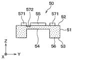
閉鎖空間SC内に収容されたトランスデューサユニット5は、電気信号と超音波振動との変換機能を有する超音波素子50を有している。すなわち、超音波素子50は、閉鎖空間SC内に収容されている。超音波素子50は、閉鎖空間SCを構成するギャップGを隔てて、ダイアフラム部45と対向配置されている。ギャップGは、閉鎖空間SCのうちの、超音波素子50とダイアフラム部45との間に位置する部分である。 The transducer unit 5 housed in the closed space SC has an ultrasonic element 50 having a function of converting an electric signal and ultrasonic vibration. That is, the ultrasonic element 50 is housed in the closed space SC. The ultrasonic element 50 is arranged to face the diaphragm portion 45 with a gap G constituting the closed space SC. The gap G is a portion of the closed space SC located between the ultrasonic element 50 and the diaphragm portion 45.

本実施形態においては、トランスデューサユニット5は、MEMS型の圧電トランスデューサとしての構成を有している。すなわち、超音波素子50は、半導体基板51に設けられたMEMS型素子である。半導体基板51は、指向軸DAに沿った厚さ方向を有するSOI基板であって、ギャップGを隔てて外側底板部42と対向配置されている。SOIはSilicon On Insulatorの略である。トランスデューサユニット5には、複数の超音波素子50が設けられている。複数の超音波素子50は、面内方向に二次元的に配列されている。 In the present embodiment, the transducer unit 5 has a configuration as a MEMS type piezoelectric transducer. That is, the ultrasonic element 50 is a MEMS type element provided on the semiconductor substrate 51. The semiconductor substrate 51 is an SOI substrate having a thickness direction along the directional axis DA, and is arranged so as to face the outer bottom plate portion 42 with a gap G interposed therebetween. SOI is an abbreviation for Silicon On Insulator. The transducer unit 5 is provided with a plurality of ultrasonic elements 50. The plurality of ultrasonic elements 50 are two-dimensionally arranged in the in-plane direction.

半導体基板51は、一対の主面である、ギャップ対向面52と接着面53とを有している。ギャップ対向面52は、半導体基板51におけるギャップGと対向する表面であって、平面状に形成されている。接着面53は、第一接着層8を介して、支持基板6と接合されている。 The semiconductor substrate 51 has a pair of main surfaces, a gap facing surface 52 and an adhesive surface 53. The gap facing surface 52 is a surface facing the gap G in the semiconductor substrate 51 and is formed in a planar shape. The adhesive surface 53 is joined to the support substrate 6 via the first adhesive layer 8.

本実施形態においては、半導体基板51は、外側底板部42から離隔して配置されている。すなわち、半導体基板51は、ギャップ対向面52の面内方向における全体が、外側底板部42と非接触となるように設けられている。また、半導体基板51は、内側底板部43によって固定的に支持されている。具体的には、内側底板部43における基板固定面40cには、第二接着層9を介して、支持基板6が固定されている。また、支持基板6には、第一接着層8を介して、半導体基板51が固定されている。 In the present embodiment, the semiconductor substrate 51 is arranged apart from the outer bottom plate portion 42. That is, the semiconductor substrate 51 is provided so that the entire gap facing surface 52 in the in-plane direction is not in contact with the outer bottom plate portion 42. Further, the semiconductor substrate 51 is fixedly supported by the inner bottom plate portion 43. Specifically, the support substrate 6 is fixed to the substrate fixing surface 40c in the inner bottom plate portion 43 via the second adhesive layer 9. Further, the semiconductor substrate 51 is fixed to the support substrate 6 via the first adhesive layer 8.

超音波素子50は、振動板部54と素子部55とを有している。振動板部54は、半導体基板51に設けられた薄肉部であって、面内方向に対向する厚肉部56の間を架け渡すように設けられている。すなわち、振動板部54は、指向軸DAに沿った厚さ方向を有する薄板状に形成されている。 The ultrasonic element 50 has a diaphragm portion 54 and an element portion 55. The diaphragm portion 54 is a thin-walled portion provided on the semiconductor substrate 51, and is provided so as to bridge between the thick-walled portions 56 facing in the in-plane direction. That is, the diaphragm portion 54 is formed in a thin plate shape having a thickness direction along the directional axis DA.

振動板部54は、トランスデューサユニット5による超音波の送信または受信の際に、撓みながら超音波振動するように設けられている。すなわち、振動板部54は、面内方向における中心部が指向軸方向に移動する態様で、ダイアフラム部45と同一方向に超音波振動するように形成されている。振動板部54は、「素子側ダイアフラム」とも称され得る。 The diaphragm portion 54 is provided so as to vibrate ultrasonic waves while bending when the transducer unit 5 transmits or receives ultrasonic waves. That is, the diaphragm portion 54 is formed so as to ultrasonically vibrate in the same direction as the diaphragm portion 45 in such a manner that the central portion in the in-plane direction moves in the direction of the directional axis. The diaphragm portion 54 may also be referred to as an “element-side diaphragm”.

振動板部54は、ギャップGを隔ててダイアフラム部45と対向配置されている。振動板部54は、ギャップ対向面52を平面状に形成するように、半導体基板51の厚さ方向における一端側に設けられている。また、本実施形態においては、半導体基板51には、複数の振動板部54が設けられている。複数の振動板部54は、面内方向に二次元的に配列されている。 The diaphragm portion 54 is arranged to face the diaphragm portion 45 across the gap G. The diaphragm portion 54 is provided on one end side in the thickness direction of the semiconductor substrate 51 so as to form the gap facing surface 52 in a planar shape. Further, in the present embodiment, the semiconductor substrate 51 is provided with a plurality of diaphragm portions 54. The plurality of diaphragm portions 54 are two-dimensionally arranged in the in-plane direction.

素子部55は、振動板部54に設けられている。本実施形態においては、素子部55は、圧電膜と薄膜電極とを積層した圧電素子であって、ギャップGと対向する表面であるギャップ対向面52上に固定されている。すなわち、超音波素子50は、PMUTとしての構成を有している。PMUTはPiezoelectric Micro-machined Ultrasonic Transducersの略である。 The element portion 55 is provided on the diaphragm portion 54. In the present embodiment, the element portion 55 is a piezoelectric element in which a piezoelectric film and a thin film electrode are laminated, and is fixed on a gap facing surface 52 which is a surface facing the gap G. That is, the ultrasonic element 50 has a configuration as a PMUT. PMUT is an abbreviation for Piezoelectric Micro-machined Ultrasonic Transducers.

超音波素子50は、素子部55に印加された交流電圧である駆動電圧に基づいて、振動板部54が超音波振動するように構成されている。また、超音波素子50は、振動板部54の振動状態に基づいて、素子部55にて出力電圧が発生するように構成されている。 The ultrasonic element 50 is configured such that the diaphragm portion 54 ultrasonically vibrates based on a drive voltage which is an AC voltage applied to the element portion 55. Further, the ultrasonic element 50 is configured so that an output voltage is generated in the element portion 55 based on the vibration state of the diaphragm portion 54.

超音波マイクロフォン3は、超音波素子50の共振周波数である第一共振周波数とダイアフラム部45の共振周波数である第二共振周波数とが一致するように構成されている。第一共振周波数は、振動板部54と素子部55との積層体を半導体基板51で支持した構造における共振周波数である。第二共振周波数は、ダイアフラム部45をダイアフラム支持部46および側板部41で支持した構造における共振周波数である。 The ultrasonic microphone 3 is configured so that the first resonance frequency, which is the resonance frequency of the ultrasonic element 50, and the second resonance frequency, which is the resonance frequency of the diaphragm portion 45, match. The first resonance frequency is a resonance frequency in a structure in which a laminate of a diaphragm portion 54 and an element portion 55 is supported by a semiconductor substrate 51. The second resonance frequency is a resonance frequency in a structure in which the diaphragm portion 45 is supported by the diaphragm support portion 46 and the side plate portion 41.

具体的には、超音波マイクロフォン3は、Δfr≦BWとなるように構成されている。Δfrは、第一共振周波数と第二共振周波数との差である。すなわち、Δfrは、ダイアフラム部45の共振周波数と超音波素子50の共振周波数とのズレ量である。BWは、超音波素子50の共振帯である第一共振帯と、ダイアフラム部45の共振帯である第二共振帯とのうちの、広い方の帯域幅である。「共振帯」とは、共振周波数をピークとする出力曲線あるいは特性曲線において、ピーク値から3dB低下する二つの周波数f1,f2間の周波数帯域である。「ピーク値から3dB低下」は、「ピーク値の1/√2倍」とも言い換えられ得る。「共振帯」は、「構造体共振の共振帯」、あるいは、「共振ピークの3dB帯」とも称され得る。帯域幅は、「-3dB帯域幅」、「3dB帯域幅」、あるいは単に「周波数帯域幅」とも称され得る。 Specifically, the ultrasonic microphone 3 is configured so that Δfr ≦ BW. Δfr is the difference between the first resonance frequency and the second resonance frequency. That is, Δfr is the amount of deviation between the resonance frequency of the diaphragm portion 45 and the resonance frequency of the ultrasonic element 50. The BW is the wider bandwidth of the first resonance band, which is the resonance band of the ultrasonic element 50, and the second resonance band, which is the resonance band of the diaphragm portion 45. The "resonance band" is a frequency band between two frequencies f1 and f2 that are 3 dB lower than the peak value in the output curve or characteristic curve having the resonance frequency as the peak. "3 dB decrease from the peak value" can be rephrased as "1 / √2 times the peak value". The "resonance band" may also be referred to as a "resonance band of structure resonance" or a "3 dB band of resonance peak". Bandwidth may also be referred to as "-3 dB bandwidth", "3 dB bandwidth", or simply "frequency bandwidth".

支持基板6は、超音波素子50を有するトランスデューサユニット5を固定的に支持する部材であって、指向軸DAに沿った厚さ方向を有する板状に形成されている。本実施形態においては、支持基板6は、回路基板であって、信号処理のための各種回路部品が実装面61上に実装されている。実装面61は、支持基板6における、ギャップGに面する側の主面である。 The support substrate 6 is a member that fixedly supports the transducer unit 5 having the ultrasonic element 50, and is formed in a plate shape having a thickness direction along the directional axis DA. In the present embodiment, the support board 6 is a circuit board, and various circuit components for signal processing are mounted on the mounting surface 61. The mounting surface 61 is the main surface of the support substrate 6 on the side facing the gap G.

支持基板6は、凹部62と凸部63とを有している。凹部62は、ギャップG側に向かって開口するように形成されている。凹部62内には、トランスデューサユニット5が収容されている。凸部63は、トランスデューサユニット5の周囲を囲むように、ギャップG側に向かって指向軸方向に突設されている。凸部63に設けられた不図示の電極パッドと、トランスデューサユニット5に設けられた不図示の電極パッドとは、ボンディングワイヤである配線7を介して電気接続されている。 The support substrate 6 has a concave portion 62 and a convex portion 63. The recess 62 is formed so as to open toward the gap G side. The transducer unit 5 is housed in the recess 62. The convex portion 63 projects in the direction of the directional axis toward the gap G side so as to surround the periphery of the transducer unit 5. An electrode pad (not shown) provided on the convex portion 63 and an electrode pad (not shown) provided on the transducer unit 5 are electrically connected via wiring 7 which is a bonding wire.

実装面61の裏面であるケース固定面64は、第二接着層9を介して、基板固定面40cと接合されている。ケース固定面64から指向軸方向における基端側に突出するように、端子65が設けられている。端子65は、図2に示されたケース本体部2a内に収容された不図示の制御回路基板と超音波マイクロフォン3とを電気接続するための接続端子である。端子65は、金属製の棒状部であって、内側底板部43を貫通するように設けられている。端子65が内側底板部43を貫通する部分は、気密的且つ液密的にシールされている。 The case fixing surface 64, which is the back surface of the mounting surface 61, is joined to the substrate fixing surface 40c via the second adhesive layer 9. The terminal 65 is provided so as to project from the case fixing surface 64 toward the base end side in the direction axis direction. The terminal 65 is a connection terminal for electrically connecting the control circuit board (not shown) housed in the case body 2a shown in FIG. 2 and the ultrasonic microphone 3. The terminal 65 is a metal rod-shaped portion and is provided so as to penetrate the inner bottom plate portion 43. The portion where the terminal 65 penetrates the inner bottom plate portion 43 is airtightly and liquidtightly sealed.

(効果)
以下、本実施形態の構成による動作概要を、同構成により奏される効果とともに、各図面を参照しつつ説明する。
(effect)
Hereinafter, an outline of the operation according to the configuration of the present embodiment will be described with reference to each drawing together with the effects produced by the configuration.

上記構成において、超音波素子50は、素子収容ケース4の内部に形成された閉鎖空間SC内に収容されている。素子収容ケース4における側板部41の一端側は、閉鎖空間SC内に水が浸入しないように、ダイアフラム部45を有する外側底板部42によって閉塞されている。このため、超音波素子50は、外側底板部42と内側底板部43によって良好に保護される。なお、素子収容ケース4の指向軸方向における基端側の部分は、センサケース2におけるマイクロフォン収容部2cによって覆われている。このため、素子収容ケース4の指向軸方向における基端側の部分から、素子収容ケース4の内部に、水あるいは異物(例えば埃等)が侵入することが、良好に抑制され得る。 In the above configuration, the ultrasonic element 50 is housed in the closed space SC formed inside the device housing case 4. One end side of the side plate portion 41 in the element accommodating case 4 is closed by the outer bottom plate portion 42 having the diaphragm portion 45 so that water does not enter the closed space SC. Therefore, the ultrasonic element 50 is well protected by the outer bottom plate portion 42 and the inner bottom plate portion 43. The portion of the element accommodating case 4 on the proximal end side in the directional axis direction is covered by the microphone accommodating portion 2c in the sensor case 2. Therefore, it is possible to satisfactorily prevent water or foreign matter (for example, dust) from entering the inside of the element accommodating case 4 from the portion on the proximal end side in the direction axis direction of the element accommodating case 4.

また、超音波素子50は、閉鎖空間SCを構成するギャップGを隔ててダイアフラム部45と対向配置されている。このため、超音波振動は、ギャップG内の媒体(例えば空気)を介して、超音波素子50とダイアフラム部45との間を伝播する。すなわち、探査波の送信時においては、駆動電圧の印加により超音波素子50にて発生した超音波振動が、ギャップG内の媒体に伝播する。ギャップG内の媒体に伝播した超音波振動は、ダイアフラム部45に伝播する。ダイアフラム部45に伝播した超音波振動により、外部空間SDに向けて探査波が送信される。逆に、受信時においては、ダイアフラム部45の振動が、ギャップG内の媒体に伝播する。ギャップG内の媒体に伝播した振動は、振動板部54に伝播する。これにより、素子部55にて出力電圧が発生する。このように、超音波振動は、ギャップG内の媒体を介した連成共振により伝播する。 Further, the ultrasonic element 50 is arranged to face the diaphragm portion 45 with a gap G constituting the closed space SC. Therefore, the ultrasonic vibration propagates between the ultrasonic element 50 and the diaphragm portion 45 via the medium (for example, air) in the gap G. That is, at the time of transmitting the exploration wave, the ultrasonic vibration generated by the ultrasonic element 50 due to the application of the driving voltage propagates to the medium in the gap G. The ultrasonic vibration propagated to the medium in the gap G propagates to the diaphragm portion 45. The ultrasonic vibration propagating to the diaphragm portion 45 transmits the exploration wave toward the external space SD. On the contrary, at the time of reception, the vibration of the diaphragm portion 45 propagates to the medium in the gap G. The vibration propagated to the medium in the gap G propagates to the diaphragm portion 54. As a result, an output voltage is generated in the element unit 55. In this way, the ultrasonic vibration propagates due to coupled resonance through the medium in the gap G.

ここで、超音波センサ1は、超音波素子50の共振周波数である第一共振周波数と、ダイアフラム部45の共振周波数である第二共振周波数とが、一致するように構成されている。したがって、超音波素子50とダイアフラム部45との間の超音波振動の伝播効率が良好となる。このように、上記構成によれば、超音波素子50を良好に保護しつつ、超音波センサ1の外部空間SDと超音波素子50との間の超音波振動の伝播を良好に実現することが可能となる。特に、超音波素子50として、バルク型よりも大出力が得られにくいMEMS型の構成を用いても、振動が連成共振により効率的に伝播することで、良好な送受信性能が実現され得る。また、車載用の超音波センサ1として、素子収容ケース4の強度確保のために外側底板部42を厚さが0.5mm以上となるように厚めに形成しても、良好な送受信性能が実現され得る。 Here, the ultrasonic sensor 1 is configured so that the first resonance frequency, which is the resonance frequency of the ultrasonic element 50, and the second resonance frequency, which is the resonance frequency of the diaphragm portion 45, match. Therefore, the propagation efficiency of ultrasonic vibration between the ultrasonic element 50 and the diaphragm portion 45 becomes good. As described above, according to the above configuration, it is possible to satisfactorily realize the propagation of ultrasonic vibration between the external space SD of the ultrasonic sensor 1 and the ultrasonic element 50 while satisfactorily protecting the ultrasonic element 50. It will be possible. In particular, even if the ultrasonic element 50 uses a MEMS type configuration in which it is difficult to obtain a larger output than the bulk type, good transmission / reception performance can be realized by efficiently propagating vibration by coupled resonance. Further, as an in-vehicle ultrasonic sensor 1, good transmission / reception performance is realized even if the outer bottom plate portion 42 is formed thick so as to have a thickness of 0.5 mm or more in order to secure the strength of the element accommodating case 4. Can be.

但し、製造上、第一共振周波数と第二共振周波数とを完全に一致させることは困難である。そこで、第一共振周波数と第二共振周波数とが実質的に一致しているものとするために、第一共振周波数と第二共振周波数との差をどの程度に収めるかが問題となる。 However, in manufacturing, it is difficult to completely match the first resonance frequency and the second resonance frequency. Therefore, in order to make the first resonance frequency and the second resonance frequency substantially match, the problem is how much the difference between the first resonance frequency and the second resonance frequency should be kept.

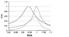
図4A~図4Eは、第一共振周波数と第二共振周波数との差を変更した場合の計算結果を示す。図4A~図4Eにおいて、破線は超音波素子50の周波数特性を示し、実線はダイアフラム部45の周波数特性を示し、点線は両者の積を示す。また、横軸は周波数を示し、縦軸は音圧を示す。縦軸および横軸は、それぞれ任意単位で示されている。横軸における「1」は70kHzである。縦軸における「1」は、ダイアフラム部45および超音波素子50の周波数特性におけるピーク値に対応する。 4A to 4E show the calculation results when the difference between the first resonance frequency and the second resonance frequency is changed. In FIGS. 4A to 4E, the broken line shows the frequency characteristic of the ultrasonic element 50, the solid line shows the frequency characteristic of the diaphragm portion 45, and the dotted line shows the product of both. The horizontal axis represents frequency and the vertical axis represents sound pressure. The vertical axis and the horizontal axis are shown in arbitrary units. "1" on the horizontal axis is 70 kHz. “1” on the vertical axis corresponds to the peak value in the frequency characteristics of the diaphragm portion 45 and the ultrasonic element 50.

図4A~図4Eの計算条件として、超音波素子50の共振帯である第一共振帯、および、ダイアフラム部45の共振帯である第二共振帯は、ともに3kHzの帯域幅を有しているものとする。すなわち、BW1=BW2=BW=3kHzである。BW1は第一共振帯の帯域幅である。BW2は第二共振帯の帯域幅である。 As the calculation conditions of FIGS. 4A to 4E, the first resonance band which is the resonance band of the ultrasonic element 50 and the second resonance band which is the resonance band of the diaphragm portion 45 both have a bandwidth of 3 kHz. It shall be. That is, BW1 = BW2 = BW = 3 kHz. BW1 is the bandwidth of the first resonance band. BW2 is the bandwidth of the second resonance band.

図4Aは、第一共振周波数と第二共振周波数とが完全に一致する場合、すなわち、Δfr=0の場合を示す。図4Bは、第二共振周波数を低周波数側に1kHzシフトした場合、すなわち、Δfr=1kHzの場合を示す。図4Cは、第二共振周波数を低周波数側に3kHzシフトした場合、すなわち、Δfr=3kHzの場合を示す。図4Dは、第二共振周波数を低周波数側に4kHzシフトした場合、すなわち、Δfr=4kHzの場合を示す。図4Eは、第二共振周波数を低周波数側に6kHzシフトした場合、すなわち、Δfr=6kHzの場合を示す。 FIG. 4A shows a case where the first resonance frequency and the second resonance frequency completely match, that is, the case where Δfr = 0. FIG. 4B shows a case where the second resonance frequency is shifted to the low frequency side by 1 kHz, that is, a case where Δfr = 1 kHz. FIG. 4C shows a case where the second resonance frequency is shifted to the low frequency side by 3 kHz, that is, a case where Δfr = 3 kHz. FIG. 4D shows a case where the second resonance frequency is shifted to the low frequency side by 4 kHz, that is, a case where Δfr = 4 kHz. FIG. 4E shows a case where the second resonance frequency is shifted to the low frequency side by 6 kHz, that is, a case where Δfr = 6 kHz.

Δfrが4kHz以上となる場合、ダイアフラム部45と超音波素子50との間の超音波振動の伝播が不良となる。これに対し、Δfrが3kHz以下となる場合、ダイアフラム部45と超音波素子50との間の超音波振動の伝播が良好となる。この点、超音波素子50の周波数特性とダイアフラム部45の周波数特性との積を示す点線の周波数特性を見ると、Δfrが4kHz以上となる図4Dおよび図4Eにて、ピークスプリットが発生している。ピークスプリットが発生すると、例えば、製品の工場出荷時の調整時に最大音圧となる周波数の回路での設定が煩雑になる。ピークスプリットが発生しない限界あるいはその近傍である、図4Cに対応するΔfr=3kHzの場合、Δfr/BW=1となる。よって、ピークスプリットが発生しない条件は、Δfr/BW≦1であるということが可能である。 When Δfr is 4 kHz or more, the propagation of ultrasonic vibration between the diaphragm portion 45 and the ultrasonic element 50 becomes poor. On the other hand, when Δfr is 3 kHz or less, the propagation of ultrasonic vibration between the diaphragm portion 45 and the ultrasonic element 50 becomes good. In this regard, looking at the frequency characteristics of the dotted line showing the product of the frequency characteristics of the ultrasonic element 50 and the frequency characteristics of the diaphragm portion 45, peak splits occur in FIGS. 4D and 4E where Δfr is 4 kHz or more. There is. When a peak split occurs, for example, the setting in the circuit of the frequency that becomes the maximum sound pressure at the time of adjusting the product at the factory is complicated. In the case of Δfr = 3 kHz corresponding to FIG. 4C, which is at or near the limit where peak split does not occur, Δfr / BW = 1. Therefore, it is possible that the condition in which the peak split does not occur is Δfr / BW ≦ 1.

図5A~図5Fは、図4A~図4Eにおける計算条件の一部を変更したものである。図5A~図5Fにおいて、超音波素子50の共振帯である第一共振帯は3kHzの帯域幅を有しており、ダイアフラム部45の共振帯である第二共振帯は6kHzの帯域幅を有しているものとする。すなわち、BW1=3kHz,BW2=6kHzである。 5A to 5F are some modifications of the calculation conditions in FIGS. 4A to 4E. In FIGS. 5A to 5F, the first resonance band, which is the resonance band of the ultrasonic element 50, has a bandwidth of 3 kHz, and the second resonance band, which is the resonance band of the diaphragm portion 45, has a bandwidth of 6 kHz. It is assumed that you are doing. That is, BW1 = 3 kHz and BW2 = 6 kHz.

図5Aは、第一共振周波数と第二共振周波数とが完全に一致する場合、すなわち、Δfr=0の場合を示す。図5Bは、第二共振周波数を低周波数側に1kHzシフトした場合、すなわち、Δfr=1kHzの場合を示す。図5Cは、第二共振周波数を低周波数側に3kHzシフトした場合、すなわち、Δfr=3kHzの場合を示す。図5Dは、第二共振周波数を低周波数側に4kHzシフトした場合、すなわち、Δfr=4kHzの場合を示す。図5Eは、第二共振周波数を低周波数側に6kHzシフトした場合、すなわち、Δfr=6kHzの場合を示す。図5Fは、第二共振周波数を低周波数側に7kHzシフトした場合、すなわち、Δfr=7kHzの場合を示す。 FIG. 5A shows a case where the first resonance frequency and the second resonance frequency completely match, that is, the case where Δfr = 0. FIG. 5B shows a case where the second resonance frequency is shifted to the low frequency side by 1 kHz, that is, a case where Δfr = 1 kHz. FIG. 5C shows a case where the second resonance frequency is shifted to the low frequency side by 3 kHz, that is, a case where Δfr = 3 kHz. FIG. 5D shows a case where the second resonance frequency is shifted to the low frequency side by 4 kHz, that is, a case where Δfr = 4 kHz. FIG. 5E shows a case where the second resonance frequency is shifted to the low frequency side by 6 kHz, that is, a case where Δfr = 6 kHz. FIG. 5F shows a case where the second resonance frequency is shifted to the low frequency side by 7 kHz, that is, a case where Δfr = 7 kHz.

Δfrが7kHz以上となる場合、ダイアフラム部45と超音波素子50との間の超音波振動の伝播が不良となる。これに対し、Δfrが6kHz以下となる場合、ダイアフラム部45と超音波素子50との間の超音波振動の伝播が良好となる。この点、超音波素子50の周波数特性とダイアフラム部45の周波数特性との積を示す点線の周波数特性を見ると、Δfrが7kHzとなる図5Fにて、ピークスプリットが発生している。ピークスプリットが発生しない限界あるいはその近傍である、図5Eに対応するΔfr=6kHzの場合、Δfr/BW1=2,Δfr/BW2=1となる。ピークよって、スプリットが発生しない条件は、Δfr/BW1≦2,Δfr/BW2≦1であるということが可能である。 When Δfr is 7 kHz or more, the propagation of ultrasonic vibration between the diaphragm portion 45 and the ultrasonic element 50 becomes poor. On the other hand, when Δfr is 6 kHz or less, the propagation of ultrasonic vibration between the diaphragm portion 45 and the ultrasonic element 50 becomes good. In this regard, looking at the frequency characteristics of the dotted line showing the product of the frequency characteristics of the ultrasonic element 50 and the frequency characteristics of the diaphragm portion 45, peak split occurs in FIG. 5F where Δfr is 7 kHz. In the case of Δfr = 6 kHz corresponding to FIG. 5E, which is at or near the limit where peak split does not occur, Δfr / BW1 = 2, Δfr / BW2 = 1. Depending on the peak, it is possible that the condition under which split does not occur is Δfr / BW1 ≦ 2, Δfr / BW2 ≦ 1.

上記の結果を総合すると、超音波マイクロフォン3を、Δfr≦BWとなるように構成することで、良好な送受信特性が得られる。BWは、BW1とBW2とのうちの大きい方である。この場合、第一共振周波数と第二共振周波数とは、実質的に一致しているものと評価することが可能である。 Summarizing the above results, good transmission / reception characteristics can be obtained by configuring the ultrasonic microphone 3 so that Δfr ≦ BW. BW is the larger of BW1 and BW2. In this case, it is possible to evaluate that the first resonance frequency and the second resonance frequency are substantially the same.

上記構成においては、素子収容ケース4は、ギャップGを含む閉鎖空間SCを、気密且つ液密に密閉するように形成されている。すなわち、超音波素子50を有するMEMS型のトランスデューサユニット5は、気密且つ液密な密閉構造を有する素子収容ケース4に収容されている。超音波素子50は、閉鎖空間SCを構成するギャップGを隔てて、ダイアフラム部45と対向配置されている。このため、ダイアフラム部45と超音波素子50との間の、ギャップG内の媒体(例えば空気)は、超音波振動を伝播する流体バネとして良好に機能する。すなわち、ギャップGを気密的に形成することで、超音波素子50とダイアフラム部45との間の疎密波の強度、つまり圧力を高めることができる。したがって、かかる構成によれば、良好な送受信特性が得られる。 In the above configuration, the element accommodating case 4 is formed so as to hermetically and liquidally seal the closed space SC including the gap G. That is, the MEMS type transducer unit 5 having the ultrasonic element 50 is housed in the element accommodating case 4 having an airtight and liquidtight sealed structure. The ultrasonic element 50 is arranged to face the diaphragm portion 45 with a gap G constituting the closed space SC. Therefore, the medium (for example, air) in the gap G between the diaphragm portion 45 and the ultrasonic element 50 functions well as a fluid spring that propagates ultrasonic vibration. That is, by forming the gap G airtightly, the intensity of the sparse and dense wave between the ultrasonic element 50 and the diaphragm portion 45, that is, the pressure can be increased. Therefore, according to such a configuration, good transmission / reception characteristics can be obtained.

ところで、超音波センサ1は、車載状態にて、頂面3bが外部空間SDに露出される。このため、素子収容ケース4における外側底板部42の外表面である頂面3bに、小石等の固い異物が衝突する場合がある。 By the way, in the ultrasonic sensor 1, the top surface 3b of the ultrasonic sensor 1 is exposed to the external space SD in the vehicle-mounted state. Therefore, a hard foreign substance such as a pebbles may collide with the top surface 3b which is the outer surface of the outer bottom plate portion 42 in the element accommodating case 4.

この点、上記構成においては、超音波素子50を有する半導体基板51は、素子収容ケース4の指向中心軸方向における一端側の内側底板部43によって、固定的に支持されている。一方、頂面3bを有する外側底板部42は、素子収容ケース4の指向中心軸方向における他端側に設けられている。さらに、半導体基板51は、ギャップGと対向するギャップ対向面52の面内方向における全体が、外側底板部42と非接触となるように、外側底板部42から離隔して配置されている。すなわち、超音波素子50は、車載状態にて外部空間SDに露出する外側底板部42には貼り付けられていない。 In this respect, in the above configuration, the semiconductor substrate 51 having the ultrasonic element 50 is fixedly supported by the inner bottom plate portion 43 on one end side in the direction center axis direction of the element accommodating case 4. On the other hand, the outer bottom plate portion 42 having the top surface 3b is provided on the other end side in the direction center axis direction of the element accommodating case 4. Further, the semiconductor substrate 51 is arranged so as to be separated from the outer bottom plate portion 42 so that the entire gap facing surface 52 facing the gap G in the in-plane direction is not in contact with the outer bottom plate portion 42. That is, the ultrasonic element 50 is not attached to the outer bottom plate portion 42 exposed to the external space SD in the vehicle-mounted state.

このため、仮に超音波マイクロフォン3の頂面3bに小石等の固い異物が衝突した場合であっても、かかる衝突に伴う衝撃は、超音波素子50には伝達されない。よって、超音波素子50におけるクラック等の発生が、良好に防止され得る。 Therefore, even if a hard foreign substance such as a pebble collides with the top surface 3b of the ultrasonic microphone 3, the impact due to the collision is not transmitted to the ultrasonic element 50. Therefore, the occurrence of cracks and the like in the ultrasonic element 50 can be satisfactorily prevented.

このように、上記構成においては、外側底板部42を厚く形成しなくても、超音波素子50におけるクラック等の不具合の発生が、良好に回避され得る。また、超音波センサ1における、超音波の送受信が、良好に行われ得る。したがって、超音波センサ1の体格の大型化を回避しつつ、超音波素子50を良好に保護することが可能となる。 As described above, in the above configuration, the occurrence of defects such as cracks in the ultrasonic element 50 can be satisfactorily avoided without forming the outer bottom plate portion 42 thickly. Further, the transmission / reception of ultrasonic waves in the ultrasonic sensor 1 can be performed satisfactorily. Therefore, it is possible to satisfactorily protect the ultrasonic element 50 while avoiding an increase in the size of the ultrasonic sensor 1.

上記構成においては、ダイアフラム部45の径方向における外縁が、厚肉のダイアフラム支持部46によって支持されている。また、ダイアフラム部45とダイアフラム支持部46とは、継ぎ目なく一体に形成されている。したがって、かかる構成によれば、外側底板部42の剛性が、良好に確保され得る。すなわち、半導体基板51および超音波素子50が、良好に保護され得る。 In the above configuration, the radial outer edge of the diaphragm portion 45 is supported by the thick-walled diaphragm support portion 46. Further, the diaphragm portion 45 and the diaphragm support portion 46 are seamlessly integrally formed. Therefore, according to such a configuration, the rigidity of the outer bottom plate portion 42 can be satisfactorily secured. That is, the semiconductor substrate 51 and the ultrasonic element 50 can be well protected.

ところで、超音波マイクロフォン3の指向性は、駆動周波数と、ダイアフラム部45の振動範囲とによって変化する。すなわち、指向角は、駆動周波数と振動範囲との積が小さくなるほど大きくなる。 By the way, the directivity of the ultrasonic microphone 3 changes depending on the drive frequency and the vibration range of the diaphragm portion 45. That is, the directivity angle increases as the product of the drive frequency and the vibration range becomes smaller.

この点、上記構成においては、外側底板部42は、ダイアフラム部45とダイアフラム支持部46とを有している。ダイアフラム部45は、外側底板部42の面内方向における中央部に設けられた薄肉部として形成されている。このため、ダイアフラム部45の面内方向におけるサイズを調整することで、指向性を良好に制御することが可能となる。 In this respect, in the above configuration, the outer bottom plate portion 42 has a diaphragm portion 45 and a diaphragm support portion 46. The diaphragm portion 45 is formed as a thin-walled portion provided in the central portion of the outer bottom plate portion 42 in the in-plane direction. Therefore, the directivity can be satisfactorily controlled by adjusting the size of the diaphragm portion 45 in the in-plane direction.

上記構成においては、超音波素子50は、MEMS型の半導体素子として、半導体基板51に形成されている。かかる構成によれば、超音波素子50における送受信性能を維持しつつ、超音波素子50を良好に小型化することが可能となる。したがって、超音波センサ1の体格を大型化させることなく、複数の超音波素子50を設けて超音波センサ1を高機能化することが可能となる。 In the above configuration, the ultrasonic element 50 is formed on the semiconductor substrate 51 as a MEMS type semiconductor element. According to such a configuration, it is possible to satisfactorily miniaturize the ultrasonic element 50 while maintaining the transmission / reception performance of the ultrasonic element 50. Therefore, it is possible to provide a plurality of ultrasonic elements 50 to enhance the functionality of the ultrasonic sensor 1 without increasing the size of the ultrasonic sensor 1.

(第二実施形態)
以下、第二実施形態について、図6を参照しつつ説明する。なお、以下の第二実施形態の説明においては、主として、第一実施形態と異なる部分について説明する。また、第一実施形態と第二実施形態とにおいて、互いに同一または均等である部分には、同一符号が付されている。したがって、以下の第二実施形態の説明において、第一実施形態と同一の符号を有する構成要素に関しては、技術的矛盾または特段の追加説明なき限り、上記の第一実施形態における説明が適宜援用され得る。
(Second embodiment)
Hereinafter, the second embodiment will be described with reference to FIG. In the following description of the second embodiment, the parts different from the first embodiment will be mainly described. Further, in the first embodiment and the second embodiment, the same or equal parts are designated by the same reference numerals. Therefore, in the following description of the second embodiment, with respect to the components having the same reference numerals as those of the first embodiment, the above description in the first embodiment is appropriately incorporated unless there is a technical contradiction or a special additional explanation. obtain.

図6に示されているように、本実施形態においては、ダイアフラム部45は、外側底板部42の面内方向におけるほぼ全部を占めるように設けられている。すなわち、素子収容ケース4は、外側底板部42の面内方向におけるほぼ全体がダイアフラム部45となるように形成されている。 As shown in FIG. 6, in the present embodiment, the diaphragm portion 45 is provided so as to occupy almost all of the outer bottom plate portion 42 in the in-plane direction. That is, the element accommodating case 4 is formed so that almost the entire outer bottom plate portion 42 in the in-plane direction becomes the diaphragm portion 45.

周知の通り、ダイアフラム部45の共振周波数は、厚さを大きくすれば高くなり、径を大きくすれば低くなる。よって、共振周波数が一定の条件において、径を大きくすれば、ダイアフラム部45の厚さを大きくすることができる。すなわち、かかる構成によれば、所定の第二共振周波数を実現するための、ダイアフラム部45における厚さを、図3の場合よりも厚くすることができる。したがって、素子収容ケース4の強度が向上する。具体的には、例えば、素子収容ケース4を合成樹脂等の軽量の材料で形成した場合における、素子収容ケース4の強度を、良好に向上することが可能となる。 As is well known, the resonance frequency of the diaphragm portion 45 increases as the thickness increases, and decreases as the diameter increases. Therefore, if the diameter is increased under the condition that the resonance frequency is constant, the thickness of the diaphragm portion 45 can be increased. That is, according to such a configuration, the thickness of the diaphragm portion 45 for realizing the predetermined second resonance frequency can be made thicker than that in the case of FIG. Therefore, the strength of the element accommodating case 4 is improved. Specifically, for example, when the element accommodating case 4 is formed of a lightweight material such as synthetic resin, the strength of the element accommodating case 4 can be satisfactorily improved.

(第三実施形態)
以下、第三実施形態について、図7を参照しつつ説明する。なお、以下の第三実施形態の説明においては、主として、第二実施形態と異なる部分について説明する。また、第二実施形態と第三実施形態とにおいて、互いに同一または均等である部分には、同一符号が付されている。したがって、以下の第三実施形態の説明において、先に説明した他の実施形態と同一の符号を有する構成要素に関しては、技術的矛盾または特段の追加説明なき限り、当該他の実施形態における説明が適宜援用され得る。後述の第四実施形態以降の他の実施形態についても同様である。
(Third embodiment)
Hereinafter, the third embodiment will be described with reference to FIG. 7. In the following description of the third embodiment, the parts different from the second embodiment will be mainly described. Further, in the second embodiment and the third embodiment, the same or equal parts are designated by the same reference numerals. Therefore, in the following description of the third embodiment, the components having the same reference numerals as those of the other embodiments described above will be described in the other embodiments unless there is a technical contradiction or a special additional description. Can be used as appropriate. The same applies to the other embodiments after the fourth embodiment described later.

図7に示されているように、本実施形態においては、素子収容ケース4には、突起470が形成されている。突起470は、素子収容ケース4におけるギャップGに面する表面である内面、具体的には素子対向面40aに設けられている。すなわち、突起470は、外側底板部42における頂面3bの裏面である素子対向面40aから、閉鎖空間SC側に向かって突設されている。 As shown in FIG. 7, in the present embodiment, the element accommodating case 4 is formed with a protrusion 470. The protrusion 470 is provided on an inner surface, specifically, an element facing surface 40a, which is a surface facing the gap G in the element accommodating case 4. That is, the protrusion 470 projects from the element facing surface 40a, which is the back surface of the top surface 3b of the outer bottom plate portion 42, toward the closed space SC side.

素子収容ケース4には、複数の突起470が設けられている。複数の突起470は、素子対向面40a上にて、面内方向に二次元的に配列されている。なお、突起470は、側方内壁面40bにも設けられ得る。 The element accommodating case 4 is provided with a plurality of protrusions 470. The plurality of protrusions 470 are two-dimensionally arranged in the in-plane direction on the element facing surface 40a. The protrusion 470 may also be provided on the side inner wall surface 40b.

かかる構成においては、ギャップG内の媒体の流れの発生が、突起470によって良好に抑制される。これにより、第一共振周波数と第二共振周波数とのズレによる影響が可及的に抑制され、第二共振帯の帯域幅BW2を大きくでき、以て送受信効率が向上する。 In such a configuration, the generation of media flow in the gap G is well suppressed by the protrusions 470. As a result, the influence of the deviation between the first resonance frequency and the second resonance frequency is suppressed as much as possible, the bandwidth BW2 of the second resonance band can be increased, and the transmission / reception efficiency is improved.

突起470は、第一共振周波数に影響しない程度のサイズおよび量で設けられ得る。なお、突起470は、典型的には、素子収容ケース4を構成する材料と同一の材料によって形成され得る。また、突起470は、典型的には、素子収容ケース4を構成する部分(例えば外側底板部42)と継ぎ目なく一体に形成され得る。しかしながら、本発明は、かかる態様に限定されない。すなわち、例えば、突起470は、素子収容ケース4を構成する材料とは異なる材料によって形成され得る。 The protrusions 470 may be provided in a size and amount that does not affect the first resonance frequency. The protrusion 470 can typically be formed of the same material as the material constituting the element housing case 4. Further, the protrusion 470 can typically be seamlessly and integrally formed with a portion constituting the element accommodating case 4 (for example, the outer bottom plate portion 42). However, the present invention is not limited to such embodiments. That is, for example, the protrusion 470 may be formed of a material different from the material constituting the element accommodating case 4.

(第四実施形態)
以下、第四実施形態について、図8を参照しつつ説明する。図8に示されているように、本実施形態においては、閉鎖空間SCには、空気よりも粘性が高い粘性流体480が充填されている。粘性流体480としては、例えば、粘度の温度依存性が小さいシリコーンオイル等が好適に用いられ得る。
(Fourth Embodiment)
Hereinafter, the fourth embodiment will be described with reference to FIG. As shown in FIG. 8, in the present embodiment, the closed space SC is filled with a viscous fluid 480 having a viscosity higher than that of air. As the viscous fluid 480, for example, silicone oil having a small temperature dependence of viscosity can be preferably used.

かかる構成においては、ギャップGには、粘性流体480が充填される。これにより、ギャップG内の媒体の流れの発生が、良好に抑制され、第二共振帯の帯域幅BW2を大きくできる。したがって、第一共振周波数と第二共振周波数とのズレによる影響が可及的に抑制され、以て送受信効率が向上する。 In such a configuration, the gap G is filled with the viscous fluid 480. As a result, the generation of the flow of the medium in the gap G is satisfactorily suppressed, and the bandwidth BW2 of the second resonance band can be increased. Therefore, the influence of the deviation between the first resonance frequency and the second resonance frequency is suppressed as much as possible, and the transmission / reception efficiency is improved.

(第五実施形態)
以下、第五実施形態について、図9を参照しつつ説明する。図9に示されているように、本実施形態においては、超音波マイクロフォン3は、ダイアフラム側検出部491とダイアフラム周波数変更部492とを備えている。
(Fifth Embodiment)
Hereinafter, the fifth embodiment will be described with reference to FIG. As shown in FIG. 9, in the present embodiment, the ultrasonic microphone 3 includes a diaphragm side detection unit 491 and a diaphragm frequency change unit 492.

ダイアフラム側検出部491は、ダイアフラム部45における応力状態に応じた出力を発生するように、ダイアフラム部45に設けられている。具体的には、ダイアフラム側検出部491は、いわゆる歪ゲージであって、頂面3bにおける、ダイアフラム部45の外縁部に対応する位置に貼り付けられている。 The diaphragm side detection unit 491 is provided in the diaphragm unit 45 so as to generate an output according to the stress state in the diaphragm unit 45. Specifically, the diaphragm side detection unit 491 is a so-called strain gauge, and is attached to a position on the top surface 3b corresponding to the outer edge portion of the diaphragm portion 45.

ダイアフラム周波数変更部492は、ダイアフラム部45の共振周波数である第二共振周波数を可変に構成されている。具体的には、ダイアフラム周波数変更部492は、バルクPZT等のバルク圧電セラミックからなる圧電素子であって、電圧印加により歪を発生するように形成されている。PZTはチタン酸ジルコン酸鉛の略称である。ダイアフラム周波数変更部492は、電圧印加時の歪によりダイアフラム部45における内部応力すなわち張力を調整するように、素子収容ケース4におけるダイアフラム部45またはその近傍位置に貼り付けられている。 The diaphragm frequency changing unit 492 is configured to have a variable second resonance frequency, which is the resonance frequency of the diaphragm unit 45. Specifically, the diaphragm frequency changing unit 492 is a piezoelectric element made of bulk piezoelectric ceramic such as bulk PZT, and is formed so as to generate distortion when a voltage is applied. PZT is an abbreviation for lead zirconate titanate. The diaphragm frequency changing portion 492 is attached to the diaphragm portion 45 or a position in the vicinity thereof in the element accommodating case 4 so as to adjust the internal stress, that is, the tension in the diaphragm portion 45 due to the strain when a voltage is applied.

超音波センサ1の動作環境温度が変化すると、ダイアフラム部45の共振周波数がシフトする。また、ダイアフラム部45に異物が付着すると、ダイアフラム部45の共振周波数がシフトする。そこで、本実施形態においては、ダイアフラム側検出部491とダイアフラム周波数変更部492とが設けられている。 When the operating environment temperature of the ultrasonic sensor 1 changes, the resonance frequency of the diaphragm portion 45 shifts. Further, when foreign matter adheres to the diaphragm portion 45, the resonance frequency of the diaphragm portion 45 shifts. Therefore, in the present embodiment, a diaphragm side detection unit 491 and a diaphragm frequency change unit 492 are provided.

ダイアフラム側検出部491は、ダイアフラム部45における応力状態に応じた出力を発生する。このため、超音波振動を超音波素子50から発振してダイアフラム部45に伝播させたときの、ダイアフラム側検出部491の出力をモニタすることで、温度変化あるいは異物付着に伴う共振周波数シフトを検知することが可能となる。また、共振周波数シフトを検知した場合に、ダイアフラム周波数変更部492を用いて、かかる周波数シフトを補償することが可能となる。 The diaphragm side detection unit 491 generates an output according to the stress state in the diaphragm unit 45. Therefore, by monitoring the output of the diaphragm side detection unit 491 when ultrasonic vibration is oscillated from the ultrasonic element 50 and propagated to the diaphragm unit 45, the resonance frequency shift due to temperature change or foreign matter adhesion is detected. It becomes possible to do. Further, when the resonance frequency shift is detected, the diaphragm frequency changing unit 492 can be used to compensate for the frequency shift.

(第六実施形態)
以下、第六実施形態について、図10を参照しつつ説明する。図10に示されているように、本実施形態においては、トランスデューサユニット5は、送受信素子501と検出素子502とを有している。
(Sixth Embodiment)
Hereinafter, the sixth embodiment will be described with reference to FIG. 10. As shown in FIG. 10, in the present embodiment, the transducer unit 5 has a transmission / reception element 501 and a detection element 502.

送受信素子501は、半導体基板51に設けられた複数のMEMS型素子のうちの1つである。検出素子502は、半導体基板51に設けられた複数のMEMS型素子のうちの他の1つである。すなわち、本実施形態においては、送受信素子501は、トランスデューサユニット5に設けられた複数の超音波素子50のうちの一部であって、超音波の送受信動作を実行するようになっている。検出素子502は、トランスデューサユニット5に設けられた複数の超音波素子50のうちの一部であって、超音波の受信動作のみを実行するようになっている。 The transmission / reception element 501 is one of a plurality of MEMS type elements provided on the semiconductor substrate 51. The detection element 502 is another one of a plurality of MEMS type elements provided on the semiconductor substrate 51. That is, in the present embodiment, the transmission / reception element 501 is a part of the plurality of ultrasonic wave elements 50 provided in the transducer unit 5 and executes the ultrasonic wave transmission / reception operation. The detection element 502 is a part of a plurality of ultrasonic wave elements 50 provided in the transducer unit 5, and is adapted to execute only the ultrasonic wave reception operation.

かかる構成において、検出素子502は、ダイアフラム部45における超音波振動がギャップG内の媒体における超音波振動を介して伝播するように、ギャップGを隔ててダイアフラム部45と対向配置されている。すなわち、検出素子502は、ダイアフラム部45の共振周波数である第二共振周波数の変化を検出するように、半導体基板51に設けられている。 In such a configuration, the detection element 502 is arranged to face the diaphragm portion 45 across the gap G so that the ultrasonic vibration in the diaphragm portion 45 propagates through the ultrasonic vibration in the medium in the gap G. That is, the detection element 502 is provided on the semiconductor substrate 51 so as to detect a change in the second resonance frequency, which is the resonance frequency of the diaphragm portion 45.

かかる構成によれば、異物付着に伴うダイアフラム部45の共振周波数シフトを、検出素子502を用いて検知することが可能となる。特に、送受信素子501と検出素子502とで共振周波数を合わせることで、異物付着の検知を高感度で行うことが可能となる。なお、送受信素子501と検出素子502との区別は、固定的であってもよいし、変更可能であってもよい。すなわち、複数の超音波素子50のうち、送受信素子501としての機能が割り当てられたものについては、その機能は固定的であってもよい。あるいは、複数の超音波素子50のうちの1つは、送受信素子501として用いられた後、検出素子502として用いられてもよい。また、複数の超音波素子50のうちの他の1つは、検出素子502として用いられた後、送受信素子501として用いられてもよい。 According to such a configuration, the resonance frequency shift of the diaphragm portion 45 due to the adhesion of foreign matter can be detected by using the detection element 502. In particular, by matching the resonance frequency between the transmission / reception element 501 and the detection element 502, it is possible to detect foreign matter adhesion with high sensitivity. The distinction between the transmission / reception element 501 and the detection element 502 may be fixed or may be changeable. That is, among the plurality of ultrasonic elements 50, those to which the function as the transmission / reception element 501 is assigned may have a fixed function. Alternatively, one of the plurality of ultrasonic elements 50 may be used as the detection element 502 after being used as the transmission / reception element 501. Further, the other one of the plurality of ultrasonic elements 50 may be used as the transmission / reception element 501 after being used as the detection element 502.

(第七実施形態)
以下、第七実施形態について、図11を参照しつつ説明する。本実施形態は、上記第六実施形態の一部を変容したものに相当する。具体的には、図11に示されているように、本実施形態においては、検出素子502には、貫通部521と振動梁部522とが設けられている。
(Seventh Embodiment)
Hereinafter, the seventh embodiment will be described with reference to FIG. 11. This embodiment corresponds to a modified version of the sixth embodiment. Specifically, as shown in FIG. 11, in the present embodiment, the detection element 502 is provided with a penetration portion 521 and a vibrating beam portion 522.

貫通部521は、振動板部54を厚さ方向に貫通するように設けられている。振動梁部522は、振動板部54に貫通部521を設けることによって形成された、面内方向に延びる片持ち梁状の部分である。すなわち、振動梁部522は、面内方向について貫通部521に隣接する遠位端である自由端が指向軸方向に沿って移動する態様で振動するように設けられている。 The penetrating portion 521 is provided so as to penetrate the diaphragm portion 54 in the thickness direction. The vibrating beam portion 522 is a cantilever-shaped portion extending in the in-plane direction formed by providing the vibrating plate portion 54 with the penetrating portion 521. That is, the vibrating beam portion 522 is provided so as to vibrate in such a manner that the free end, which is the distal end adjacent to the penetrating portion 521 in the in-plane direction, moves along the direction of the directional axis.

かかる構成によれば、上記第六実施形態と同様の効果が奏され得る。また、かかる構成によれば、振動梁部522における形状を調整することで、検出素子502の共振周波数を任意に設定することが可能となる。よって、例えば、トランスデューサユニット5における検出素子502の占有面積を抑制することで、製造プロセスを変更することなくチップサイズの小型化が可能となる。 According to such a configuration, the same effect as that of the sixth embodiment can be obtained. Further, according to such a configuration, the resonance frequency of the detection element 502 can be arbitrarily set by adjusting the shape of the vibrating beam portion 522. Therefore, for example, by suppressing the occupied area of the detection element 502 in the transducer unit 5, the chip size can be reduced without changing the manufacturing process.

(第八実施形態)
以下、第八実施形態について、図12を参照しつつ説明する。図12に示されているように、本実施形態においては、検出素子502は、複数の超音波素子50とは異なる素子として設けられている。
(Eighth embodiment)
Hereinafter, the eighth embodiment will be described with reference to FIG. As shown in FIG. 12, in the present embodiment, the detection element 502 is provided as an element different from the plurality of ultrasonic elements 50.

検出素子502は、半導体基板51における厚肉部56に設けられている。具体的には、検出素子502は、厚肉部56に対応する位置に形成された圧電積層体523によって構成されている。圧電積層体523は、圧電素子であって、圧電膜と薄膜電極とを積層することによって形成されている。 The detection element 502 is provided on the thick portion 56 of the semiconductor substrate 51. Specifically, the detection element 502 is composed of a piezoelectric laminated body 523 formed at a position corresponding to the thick portion 56. The piezoelectric laminated body 523 is a piezoelectric element, and is formed by laminating a piezoelectric film and a thin film electrode.

かかる構成においては、ギャップG内の媒体に伝播した超音波振動により、圧電積層体523に応力が作用する。具体的には、ギャップG内の媒体の超音波振動が、圧電積層体523に直接作用することで、圧電積層体523に圧縮応力が発生する。また、ギャップG内の媒体の超音波振動が、面内方向について検出素子502に隣接する振動板部54に伝播することで、かかる振動板部54が振動する。かかる振動板部54の振動に伴い、圧電積層体523が設けられた厚肉部56における、ギャップ対向面52の近傍部分に、曲げ応力が作用する。かかる曲げ応力は、圧電積層体523に作用する。 In such a configuration, stress acts on the piezoelectric laminate 523 due to the ultrasonic vibration propagating in the medium in the gap G. Specifically, the ultrasonic vibration of the medium in the gap G acts directly on the piezoelectric laminate 523, so that compressive stress is generated in the piezoelectric laminate 523. Further, the ultrasonic vibration of the medium in the gap G propagates to the diaphragm portion 54 adjacent to the detection element 502 in the in-plane direction, so that the diaphragm portion 54 vibrates. Along with the vibration of the diaphragm portion 54, bending stress acts on a portion in the vicinity of the gap facing surface 52 in the thick portion 56 provided with the piezoelectric laminated body 523. The bending stress acts on the piezoelectric laminate 523.

圧電積層体523に作用した応力により、圧電積層体523に出力電圧が発生する。かかる出力電圧に基づいて、ダイアフラム部45の共振周波数である第二共振周波数の変化を検出することが可能となる。したがって、温度変化あるいは異物付着に伴う、ダイアフラム部45の共振周波数シフトを、可及的に簡略な装置構成により検知することが可能となる。 An output voltage is generated in the piezoelectric laminate 523 due to the stress acting on the piezoelectric laminate 523. Based on such an output voltage, it is possible to detect a change in the second resonance frequency, which is the resonance frequency of the diaphragm portion 45. Therefore, it is possible to detect the resonance frequency shift of the diaphragm portion 45 due to the temperature change or the adhesion of foreign matter with the simplest possible device configuration.

(第九実施形態)
以下、第九実施形態について、図13を参照しつつ説明する。本実施形態は、上記の第七実施形態と第八実施形態とを複合適用したものに相当する。
(Ninth Embodiment)
Hereinafter, the ninth embodiment will be described with reference to FIG. The present embodiment corresponds to a combined application of the seventh embodiment and the eighth embodiment described above.

具体的には、図13に示されているように、本実施形態においては、検出素子502は、素子部55が設けられていない振動板部54と、これに面内方向について隣接する厚肉部56に設けられた圧電積層体523とによって形成されている。かかる構成によれば、上記第七実施形態と同様の効果が奏され得る。 Specifically, as shown in FIG. 13, in the present embodiment, the detection element 502 is a diaphragm portion 54 in which the element portion 55 is not provided, and a thick wall adjacent to the diaphragm portion 54 in the in-plane direction. It is formed by a piezoelectric laminated body 523 provided in the portion 56. According to such a configuration, the same effect as that of the seventh embodiment can be obtained.

(第十実施形態)
以下、第十実施形態について、図14を参照しつつ説明する。図14に示されているように、本実施形態においては、超音波素子50は、振動板部54と、素子部55と、素子周波数変更部571とを有している。
(10th Embodiment)
Hereinafter, the tenth embodiment will be described with reference to FIG. As shown in FIG. 14, in the present embodiment, the ultrasonic element 50 has a diaphragm portion 54, an element portion 55, and an element frequency changing portion 571.

素子周波数変更部571は、超音波素子50の共振周波数である第一共振周波数を可変に構成されている。具体的には、素子周波数変更部571は、例えば、半導体基板51に設けられた薄膜状のヒータによって構成され得る。あるいは、素子周波数変更部571は、例えば、半導体基板51に設けられた圧電素子によって構成され得る。 The element frequency changing unit 571 is configured to have a variable first resonance frequency, which is the resonance frequency of the ultrasonic element 50. Specifically, the element frequency changing unit 571 may be configured by, for example, a thin-film heater provided on the semiconductor substrate 51. Alternatively, the element frequency changing unit 571 may be configured by, for example, a piezoelectric element provided on the semiconductor substrate 51.

素子周波数変更部571は、面内方向について、素子部55の周囲に設けられ得る。具体的には、素子周波数変更部571は、ギャップ対向面52上に形成され得る。 The element frequency changing unit 571 may be provided around the element unit 55 in the in-plane direction. Specifically, the element frequency changing unit 571 may be formed on the gap facing surface 52.

かかる構成によれば、素子周波数変更部571を用いて、超音波素子50の共振周波数である第一共振周波数を変更することが可能となる。したがって、第一共振周波数と、ダイアフラム部45の共振周波数である第二共振周波数との差を、可及的に小さくすることが可能となる。 According to such a configuration, it is possible to change the first resonance frequency, which is the resonance frequency of the ultrasonic element 50, by using the element frequency changing unit 571. Therefore, the difference between the first resonance frequency and the second resonance frequency, which is the resonance frequency of the diaphragm portion 45, can be made as small as possible.

(第十一実施形態)
以下、第十一実施形態について、図15を参照しつつ説明する。図15に示されているように、本実施形態においては、超音波素子50は、振動板部54と、素子部55と、素子周波数変更部571と、素子側検出部572とを有している。
(Eleventh Embodiment)
Hereinafter, the eleventh embodiment will be described with reference to FIG. As shown in FIG. 15, in the present embodiment, the ultrasonic element 50 has a diaphragm unit 54, an element unit 55, an element frequency changing unit 571, and an element side detection unit 527. There is.

素子側検出部572は、振動板部54における応力状態に応じた出力を発生するように、振動板部54に設けられている。具体的には、素子側検出部572は、いわゆる歪ゲージであって、振動板部54の面内方向における外縁部に設けられている。すなわち、超音波素子50は、ダイアフラム部45の共振周波数である第二共振周波数の変化を、素子側検出部572により検出するように構成されている。 The element side detection unit 572 is provided in the diaphragm unit 54 so as to generate an output according to the stress state in the diaphragm unit 54. Specifically, the element side detection unit 572 is a so-called strain gauge, and is provided on the outer edge portion of the diaphragm portion 54 in the in-plane direction. That is, the ultrasonic element 50 is configured to detect a change in the second resonance frequency, which is the resonance frequency of the diaphragm unit 45, by the element side detection unit 572.

上記の通り、ダイアフラム部45と超音波素子50との間の、ギャップG内の媒体(例えば空気)は、超音波振動を伝播する流体バネとして機能する。すなわち、ダイアフラム部45と超音波素子50とは、ギャップG内の媒体に対応する流体バネを介して弾性的に接続された状態となっている。このため、異物付着等によってダイアフラム部45の共振周波数が変化すると、かかる変化の影響は、ギャップG内の媒体に対応する流体バネを介して、超音波素子50にも作用する。 As described above, the medium (for example, air) in the gap G between the diaphragm portion 45 and the ultrasonic element 50 functions as a fluid spring that propagates ultrasonic vibration. That is, the diaphragm portion 45 and the ultrasonic element 50 are in a state of being elastically connected via a fluid spring corresponding to the medium in the gap G. Therefore, when the resonance frequency of the diaphragm portion 45 changes due to foreign matter adhesion or the like, the influence of such a change also acts on the ultrasonic element 50 via the fluid spring corresponding to the medium in the gap G.

そこで、本実施形態においては、超音波素子50における振動板部54には、素子側検出部572が設けられている。素子側検出部572は、振動板部54における応力状態に応じた出力を発生する。したがって、素子側検出部572の出力に基づいて、ダイアフラム部45の共振周波数シフトを検知することが可能となる。 Therefore, in the present embodiment, the element side detection unit 572 is provided on the diaphragm unit 54 of the ultrasonic element 50. The element side detection unit 572 generates an output according to the stress state in the diaphragm unit 54. Therefore, it is possible to detect the resonance frequency shift of the diaphragm unit 45 based on the output of the element side detection unit 572.

(変形例)
本発明は、上記実施形態に限定されるものではない。故に、上記実施形態に対しては、適宜変更が可能である。以下、代表的な変形例について説明する。以下の変形例の説明においては、上記実施形態との相違点を主として説明する。また、上記実施形態と変形例とにおいて、互いに同一または均等である部分には、同一符号が付されている。したがって、以下の変形例の説明において、上記実施形態と同一の符号を有する構成要素に関しては、技術的矛盾または特段の追加説明なき限り、上記実施形態における説明が適宜援用され得る。
(Modification example)
The present invention is not limited to the above embodiment. Therefore, the above embodiment can be changed as appropriate. Hereinafter, a typical modification will be described. In the following description of the modification, the differences from the above embodiment will be mainly described. Further, in the above-described embodiment and the modified example, the same or equal parts are designated by the same reference numerals. Therefore, in the following description of the modification, the description in the above embodiment may be appropriately incorporated with respect to the components having the same reference numerals as those in the above embodiment, unless there is a technical contradiction or a special additional explanation.

超音波センサ1は、車載用に限定されない。また、超音波センサ1は、クリアランスソナーに限定されない。すなわち、超音波センサ1は、他の用途にも用いられ得る。 The ultrasonic sensor 1 is not limited to an in-vehicle use. Further, the ultrasonic sensor 1 is not limited to the clearance sonar. That is, the ultrasonic sensor 1 can be used for other purposes.

超音波センサ1は、超音波を送受信可能な構成に限定されない。すなわち、例えば、超音波センサ1は、超音波の発信のみが可能な構成を有していてもよい。あるいは、超音波センサ1は、他の超音波発信器から発信された超音波である探査波の、周囲に存在する物体による反射波を受信する機能のみを有するものであってもよい。 The ultrasonic sensor 1 is not limited to a configuration capable of transmitting and receiving ultrasonic waves. That is, for example, the ultrasonic sensor 1 may have a configuration capable of transmitting only ultrasonic waves. Alternatively, the ultrasonic sensor 1 may have only a function of receiving a reflected wave of an exploration wave, which is an ultrasonic wave transmitted from another ultrasonic transmitter, by an object existing in the surroundings.

超音波センサ1における各部の構成も、上記具体例に限定されない。具体的には、例えば、超音波マイクロフォン3すなわち素子収容ケース4の外形形状は、略円柱状に限定されず、略正六角柱状、略正八角柱状、等であってもよい。 The configuration of each part of the ultrasonic sensor 1 is not limited to the above specific example. Specifically, for example, the outer shape of the ultrasonic microphone 3, that is, the element accommodating case 4, is not limited to a substantially cylindrical shape, and may be a substantially regular hexagonal columnar shape, a substantially regular octagonal columnar shape, or the like.

ギャップGを構成する、素子収容ケース4の内部の閉鎖空間SCには、乾燥空気が封入されていてもよい。これにより、超音波マイクロフォン3内部の各部、例えば、超音波素子50における、水分の存在による劣化の発生が、良好に抑制され得る。 Dry air may be sealed in the closed space SC inside the element accommodating case 4 constituting the gap G. As a result, the occurrence of deterioration due to the presence of water in each part inside the ultrasonic microphone 3, for example, the ultrasonic element 50 can be satisfactorily suppressed.

あるいは、例えば、閉鎖空間SCには、乾燥窒素ガス等の乾燥不活性ガスが、1気圧以上の圧力で封入されていてもよい。これにより、超音波マイクロフォン3内部の各部の、水分または酸化による劣化の発生が、良好に抑制され得る。また、超音波素子50とダイアフラム部45との間の疎密波の強度を高めることができ、以て送受信性能を高めることが可能となる。 Alternatively, for example, the closed space SC may be filled with a dry inert gas such as dry nitrogen gas at a pressure of 1 atm or more. As a result, the generation of deterioration due to moisture or oxidation in each part inside the ultrasonic microphone 3 can be satisfactorily suppressed. Further, the intensity of the sparse and dense wave between the ultrasonic element 50 and the diaphragm portion 45 can be increased, and thus the transmission / reception performance can be improved.

なお、閉鎖空間SC内の媒体種類および圧力についても、特段の限定はない。 There are no particular restrictions on the type of medium and pressure in the closed space SC.

素子収容ケース4を構成する材料は、上記の具体例に限定されない。すなわち、例えば、素子収容ケース4は、アルミニウムまたはアルミニウム合金によって形成され得る。あるいは、素子収容ケース4は、他の種類の金属材料によっても形成され得る。あるいは、素子収容ケース4は、ポリカーボネート、ポリスチレン、等の合成樹脂材料によっても形成され得る。あるいは、素子収容ケース4は、炭素繊維、炭素繊維含有樹脂、等によっても形成され得る。 The material constituting the element accommodating case 4 is not limited to the above specific example. That is, for example, the element housing case 4 may be formed of aluminum or an aluminum alloy. Alternatively, the element housing case 4 may also be formed of other types of metallic materials. Alternatively, the element housing case 4 can also be formed of a synthetic resin material such as polycarbonate, polystyrene, or the like. Alternatively, the element accommodating case 4 may be formed of carbon fiber, a carbon fiber-containing resin, or the like.

素子収容ケース4の構造についても、技術的な不都合が生じない限り、特段の限定はない。具体的には、例えば、ダイアフラム部45とダイアフラム支持部46とは、異なる材料によって形成されていてもよい。 The structure of the element accommodating case 4 is not particularly limited as long as technical inconvenience does not occur. Specifically, for example, the diaphragm portion 45 and the diaphragm support portion 46 may be formed of different materials.

ダイアフラム部45の面内方向における形状としては、略矩形、略円形、略楕円形、略正六角形、略正八角形、等の任意の形状が採用可能である。同様に、ダイアフラム部45の断面形状も、平板状に限定されない。具体的には、例えば、ダイアフラム部45は、外部空間SDに向かって突出する曲板状に形成されていてもよい。 As the shape of the diaphragm portion 45 in the in-plane direction, any shape such as a substantially rectangular shape, a substantially circular shape, a substantially elliptical shape, a substantially regular hexagonal shape, and a substantially regular octagonal shape can be adopted. Similarly, the cross-sectional shape of the diaphragm portion 45 is not limited to the flat plate shape. Specifically, for example, the diaphragm portion 45 may be formed in the shape of a curved plate protruding toward the external space SD.

上記の各実施形態において、半導体基板51は、内側底板部43によって固定的に支持されていた。しかしながら、本発明は、かかる態様に限定されない。すなわち、例えば、半導体基板51は、側板部41によって固定的に支持されていてもよい。具体的には、例えば、支持基板6の素子収容ケース4に対する固定は、側板部41にて行われ得る。 In each of the above embodiments, the semiconductor substrate 51 is fixedly supported by the inner bottom plate portion 43. However, the present invention is not limited to such embodiments. That is, for example, the semiconductor substrate 51 may be fixedly supported by the side plate portion 41. Specifically, for example, the support substrate 6 can be fixed to the element accommodating case 4 at the side plate portion 41.

上記の各実施形態において、半導体基板51は、外側底板部42から離隔して配置されていた。しかしながら、本発明は、かかる態様に限定されない。すなわち、例えば、図16に示されているように、半導体基板51は、外側底板部42におけるダイアフラム支持部46と当接していてもよい。この場合、ギャップGは、ダイアフラム部45とダイアフラム支持部46と半導体基板51とによって囲まれた閉鎖的な空間によって形成される。 In each of the above embodiments, the semiconductor substrate 51 is arranged apart from the outer bottom plate portion 42. However, the present invention is not limited to such embodiments. That is, for example, as shown in FIG. 16, the semiconductor substrate 51 may be in contact with the diaphragm support portion 46 in the outer bottom plate portion 42. In this case, the gap G is formed by a closed space surrounded by the diaphragm portion 45, the diaphragm support portion 46, and the semiconductor substrate 51.

かかる構成においても、超音波素子50それ自体は、ギャップGを挟んで外側底板部42と対向しつつ、外側底板部42から離隔している。すなわち、超音波素子50は、車載状態にて外部空間SDに露出する外側底板部42には貼り付けられていない。このため、仮に超音波マイクロフォン3の頂面3bに小石等の固い異物が衝突した場合であっても、超音波素子50におけるクラック等の発生が、良好に防止され得る。 Even in such a configuration, the ultrasonic element 50 itself is separated from the outer bottom plate portion 42 while facing the outer bottom plate portion 42 with the gap G interposed therebetween. That is, the ultrasonic element 50 is not attached to the outer bottom plate portion 42 exposed to the external space SD in the vehicle-mounted state. Therefore, even if a hard foreign substance such as a pebble collides with the top surface 3b of the ultrasonic microphone 3, the occurrence of cracks or the like in the ultrasonic element 50 can be satisfactorily prevented.

例えば、半導体基板51の一主面であるギャップ対向面52における、ダイアフラム支持部46と対向する部分は、ダイアフラム支持部46と気密的に接合され得る。この場合、閉鎖空間SCのうちのギャップGのみが気密空間であってもよい。 For example, the portion of the gap facing surface 52, which is one main surface of the semiconductor substrate 51, facing the diaphragm support portion 46 can be airtightly joined to the diaphragm support portion 46. In this case, only the gap G in the closed space SC may be an airtight space.

図7に示された第三実施形態に係る超音波マイクロフォン3に設けられた突起470は、他の実施形態にも適用可能である。すなわち、例えば、突起470は、上記第一実施形態にも適用可能である。また、例えば、突起470は、上記第四実施形態~第十一実施形態にも適用可能である。 The protrusion 470 provided on the ultrasonic microphone 3 according to the third embodiment shown in FIG. 7 can be applied to other embodiments. That is, for example, the protrusion 470 is also applicable to the first embodiment. Further, for example, the protrusion 470 can also be applied to the fourth to eleventh embodiments described above.

図9を参照すると、温度変化は、ダイアフラム側検出部491の出力を用いなくても、センサケース2または素子収容ケース4内に設けられる不図示の温度センサの出力を用いて補償可能である。あるいは、温度変化は、ECU等の外部装置から温度情報を入手することで補償可能である。よって、ダイアフラム側検出部491は、省略され得る。あるいは、ダイアフラム側検出部491は、異物付着検知のために設けられていてもよい。これにより、ダイアフラム周波数変更部492を用いて温度補償を行いつつ、ダイアフラム側検出部491を用いて異物付着検知を行うことが可能となる。 Referring to FIG. 9, the temperature change can be compensated by using the output of a temperature sensor (not shown) provided in the sensor case 2 or the element accommodating case 4 without using the output of the diaphragm side detection unit 491. Alternatively, the temperature change can be compensated by obtaining temperature information from an external device such as an ECU. Therefore, the diaphragm side detection unit 491 may be omitted. Alternatively, the diaphragm side detection unit 491 may be provided for detecting foreign matter adhesion. This makes it possible to detect foreign matter adhesion using the diaphragm side detection unit 491 while performing temperature compensation using the diaphragm frequency changing unit 492.

トランスデューサユニット5の構成についても、特段の限定はない。すなわち、例えば、図17に示されているように、超音波素子50は、バルクPZT等のバルク圧電セラミックからなる圧電素子であってもよい。これにより、探査波発進時にて大きな音圧を得ることが可能となる。 There are no particular restrictions on the configuration of the transducer unit 5. That is, for example, as shown in FIG. 17, the ultrasonic element 50 may be a piezoelectric element made of bulk piezoelectric ceramic such as bulk PZT. This makes it possible to obtain a large sound pressure when the exploration wave starts.

トランスデューサユニット5に設けられる超音波素子50の個数についても、特段の限定はない。すなわち、例えば、各図に示されているように、超音波素子50は、面内方向に二次元的に複数個配列され得る。かかる構成によれば、送受信方向の制御が可能なフェーズドアレイ型の超音波センサ1を、良好に小型化することが可能となる。なお、この場合、ダイアフラム部45もまた、超音波素子50の面内方向位置と対応するように、面内方向に二次元的に複数個配列され得る。すなわち、ダイアフラム部45は、複数に分割され得る。 The number of ultrasonic elements 50 provided in the transducer unit 5 is also not particularly limited. That is, for example, as shown in each figure, a plurality of ultrasonic elements 50 can be two-dimensionally arranged in the in-plane direction. According to such a configuration, the phased array type ultrasonic sensor 1 capable of controlling the transmission / reception direction can be satisfactorily miniaturized. In this case, the diaphragm portion 45 may also be two-dimensionally arranged in the in-plane direction so as to correspond to the in-plane position of the ultrasonic element 50. That is, the diaphragm portion 45 can be divided into a plurality of parts.

あるいは、トランスデューサユニット5には、超音波素子50が1個のみ設けられていてもよい。これにより、超音波マイクロフォン3の小型化が可能となる。 Alternatively, the transducer unit 5 may be provided with only one ultrasonic element 50. This makes it possible to reduce the size of the ultrasonic microphone 3.

超音波素子50の種類についても、特段の限定はない。すなわち、例えば、超音波素子50は、PMUTに限定されない。超音波素子50は、CMUTとしての構成を有していてもよい。CMUTはCapacitive Micro-machined Ultrasound Transducerの略である。 There are no particular restrictions on the type of ultrasonic element 50. That is, for example, the ultrasonic element 50 is not limited to PMUT. The ultrasonic element 50 may have a configuration as a CMUT. CMUT is an abbreviation for Capacitive Micro-machined Ultrasound Transducer.

支持基板6は、回路基板ではなくてもよい。すなわち、信号処理のための各種回路部品は、半導体基板51上に実装されていてもよい。あるいは、かかる回路部品は、ケース本体部2aの内側に設けられた不図示の制御回路基板上に実装されていてもよい。 The support board 6 does not have to be a circuit board. That is, various circuit components for signal processing may be mounted on the semiconductor substrate 51. Alternatively, such circuit components may be mounted on a control circuit board (not shown) provided inside the case main body 2a.

トランスデューサユニット5と支持基板6との電気接続は、配線7を用いた方式に限定されない。すなわち、例えば、第一接着層8は、ハンダ等の導電性接合層であってもよい。 The electrical connection between the transducer unit 5 and the support substrate 6 is not limited to the method using the wiring 7. That is, for example, the first adhesive layer 8 may be a conductive bonding layer such as solder.

支持基板6は、省略され得る。すなわち、半導体基板51は、素子収容ケース4に直接的に固定され得る。 The support substrate 6 may be omitted. That is, the semiconductor substrate 51 can be directly fixed to the element housing case 4.

上記の説明において、互いに継ぎ目無く一体に形成されていた複数の構成要素は、互いに別体の部材を貼り合わせることによって形成されてもよい。同様に、互いに別体の部材を貼り合わせることによって形成されていた複数の構成要素は、互いに継ぎ目無く一体に形成されてもよい。 In the above description, the plurality of components that are seamlessly and integrally formed with each other may be formed by laminating separate members from each other. Similarly, a plurality of components formed by laminating separate members may be seamlessly and integrally formed with each other.

上記の説明において、互いに同一の材料によって形成されていた複数の構成要素は、互いに異なる材料によって形成されてもよい。同様に、互いに異なる材料によって形成されていた複数の構成要素は、互いに同一の材料によって形成されてもよい。 In the above description, the plurality of components formed of the same material may be formed of different materials. Similarly, a plurality of components that were formed of different materials may be formed of the same material.

上記実施形態を構成する要素は、特に必須であると明示した場合および原理的に明らかに必須であると考えられる場合等を除き、必ずしも必須のものではないことは言うまでもない。また、構成要素の個数、数値、量、範囲等の数値が言及されている場合、特に必須であると明示した場合および原理的に明らかに特定の数に限定される場合等を除き、その特定の数に本発明が限定されることはない。同様に、構成要素等の形状、方向、位置関係等が言及されている場合、特に必須であると明示した場合および原理的に特定の形状、方向、位置関係等に限定される場合等を除き、その形状、方向、位置関係等に本発明が限定されることはない。 It goes without saying that the elements constituting the above embodiment are not necessarily essential except when it is clearly stated that they are essential and when they are clearly considered to be essential in principle. In addition, when numerical values such as the number, numerical value, quantity, range, etc. of components are mentioned, the specification is specified except when it is clearly stated that it is indispensable or when it is clearly limited to a specific number in principle. The present invention is not limited to the number of. Similarly, except when the shape, direction, positional relationship, etc. of the constituent elements are mentioned, when it is clearly stated that it is particularly essential, or when it is limited to a specific shape, direction, positional relationship, etc. in principle. The present invention is not limited to the shape, direction, positional relationship, and the like.

変形例も、上記の例示に限定されない。すなわち、例えば、複数の実施形態が、技術的に矛盾しない限り、互いに組み合わされ得る。同様に、複数の変形例が、技術的に矛盾しない限り、互いに組み合わされ得る。 Modifications are also not limited to the above examples. That is, for example, a plurality of embodiments can be combined with each other as long as they are not technically inconsistent. Similarly, multiple variants can be combined with each other as long as they are not technically inconsistent.

1 超音波センサ
3 超音波マイクロフォン
4 素子収容ケース
41 側板部
42 外側底板部
45 ダイアフラム部
50 超音波素子
DA 指向軸
G ギャップ
SC 閉鎖空間
1 Ultrasonic sensor 3 Ultrasonic microphone 4 Element housing case 41 Side plate 42 Outer bottom plate 45 Diaphragm 50 Ultrasonic element DA directional axis G gap SC Closed space

Claims (16)

超音波センサ(1)であって、
内部に閉鎖空間(SC)を有する箱状に形成されていて、指向軸(DA)を囲むように形成された側板部(41)と前記側板部の一端側を閉塞する外側底板部(42)とを有する、素子収容ケース(4)と、
前記閉鎖空間内に収容されていて、電気信号と超音波振動との変換機能を有する、超音波素子(50)と、
を備え、
前記素子収容ケースにおける前記外側底板部は、前記指向軸に沿った厚さ方向を有するダイアフラム部(45)を有し、
前記超音波素子は、前記閉鎖空間を構成するギャップ(G)を隔てて前記ダイアフラム部と対向配置され、
前記超音波素子の共振周波数である第一共振周波数と、前記ダイアフラム部の共振周波数である第二共振周波数とが、一致するように構成された、
超音波センサ。
An ultrasonic sensor (1)
A side plate portion (41) formed in a box shape having a closed space (SC) inside and surrounded by a directional axis (DA) and an outer bottom plate portion (42) that closes one end side of the side plate portion. The element accommodating case (4) having
An ultrasonic element (50) housed in the closed space and having a function of converting an electric signal and ultrasonic vibration, and an ultrasonic element (50).
Equipped with
The outer bottom plate portion in the element accommodating case has a diaphragm portion (45) having a thickness direction along the directional axis.
The ultrasonic element is arranged to face the diaphragm portion with a gap (G) constituting the closed space.
The first resonance frequency, which is the resonance frequency of the ultrasonic element, and the second resonance frequency, which is the resonance frequency of the diaphragm portion, are configured to match.
Ultrasonic sensor.
前記素子収容ケースは、前記閉鎖空間を気密且つ液密に密閉するように形成された、
請求項1に記載の超音波センサ。
The element accommodating case is formed so as to hermetically and liquidally seal the closed space.
The ultrasonic sensor according to claim 1.
前記第一共振周波数と前記第二共振周波数との差をΔfrとし、前記超音波素子の共振帯である第一共振帯と前記ダイアフラム部の共振帯である第二共振帯とのうちの広い方の帯域幅をBWとすると、Δfr≦BWとなるように構成された、
請求項1または2に記載の超音波センサ。
The difference between the first resonance frequency and the second resonance frequency is Δfr, and the wider of the first resonance band, which is the resonance band of the ultrasonic element, and the second resonance band, which is the resonance band of the diaphragm portion. If the bandwidth of is BW, it is configured so that Δfr ≦ BW.
The ultrasonic sensor according to claim 1 or 2.
前記超音波素子は、前記指向軸に沿った厚さ方向を有していて前記ギャップを隔てて前記外側底板部と対向配置された半導体基板(51)に設けられたMEMS型素子である、
請求項1~3のいずれか1つに記載の超音波センサ。
The ultrasonic element is a MEMS type element provided on a semiconductor substrate (51) having a thickness direction along the directional axis and arranged opposite to the outer bottom plate portion across the gap.
The ultrasonic sensor according to any one of claims 1 to 3.
前記半導体基板における前記ギャップと対向する表面であるギャップ対向面(52)の、前記指向軸と交差する面内方向における全体が、前記外側底板部と非接触となるように、前記半導体基板が前記外側底板部から離隔して配置された、
請求項4に記載の超音波センサ。
The semiconductor substrate is such that the entire gap facing surface (52), which is the surface of the semiconductor substrate facing the gap, in the in-plane direction intersecting the directional axis is not in contact with the outer bottom plate portion. Arranged away from the outer bottom plate,
The ultrasonic sensor according to claim 4.
前記素子収容ケースは、前記側板部の他端側を閉塞する内側底板部(43)をさらに備え、
前記半導体基板は、前記内側底板部によって固定的に支持された、
請求項5に記載の超音波センサ。
The element accommodating case further includes an inner bottom plate portion (43) that closes the other end side of the side plate portion.
The semiconductor substrate was fixedly supported by the inner bottom plate portion.
The ultrasonic sensor according to claim 5.
前記ダイアフラム部における超音波振動が前記ギャップ内の媒体における超音波振動を介して伝播するように前記ギャップを隔てて前記ダイアフラム部と対向配置されることで、前記ダイアフラム部における前記第二共振周波数の変化を検出するように、前記半導体基板に設けられた検出素子(502)をさらに備えた、
請求項4~6のいずれか1つに記載の超音波センサ。
By arranging the ultrasonic vibration in the diaphragm portion facing the diaphragm portion across the gap so that the ultrasonic vibration in the diaphragm propagates through the ultrasonic vibration in the medium in the gap, the second resonance frequency of the diaphragm portion is reached. A detection element (502) provided on the semiconductor substrate is further provided so as to detect a change.
The ultrasonic sensor according to any one of claims 4 to 6.
前記超音波素子は、前記半導体基板に設けられた複数の前記MEMS型素子のうちの1つであり、
前記検出素子は、前記半導体基板に設けられた複数の前記MEMS型素子のうちの他の1つである、
請求項7に記載の超音波センサ。
The ultrasonic element is one of a plurality of the MEMS type elements provided on the semiconductor substrate.
The detection element is another one of the plurality of MEMS type elements provided on the semiconductor substrate.
The ultrasonic sensor according to claim 7.
前記超音波素子は、
前記指向軸に沿った厚さ方向を有していて前記ギャップを隔てて前記ダイアフラム部と対向配置された振動板部(54)と、
前記振動板部における応力状態に応じた出力を発生するように前記振動板部に設けられた素子側検出部(572)と、
を有する、
請求項1~8のいずれか1つに記載の超音波センサ。
The ultrasonic element is
A diaphragm portion (54) having a thickness direction along the directional axis and arranged to face the diaphragm portion across the gap.
The element side detection unit (572) provided in the diaphragm portion so as to generate an output according to the stress state in the diaphragm portion, and
Have,
The ultrasonic sensor according to any one of claims 1 to 8.
前記超音波素子は、前記ダイアフラム部における前記第二共振周波数の変化を前記素子側検出部により検出するように構成された、
請求項9に記載の超音波センサ。
The ultrasonic element is configured to detect a change in the second resonance frequency in the diaphragm portion by the element-side detection unit.
The ultrasonic sensor according to claim 9.
前記超音波素子における前記第一共振周波数を可変に構成された素子周波数変更部(571)をさらに備えた、
請求項1~10のいずれか1つに記載の超音波センサ。
Further, an element frequency changing unit (571) having a variable first resonance frequency in the ultrasonic element is provided.
The ultrasonic sensor according to any one of claims 1 to 10.
前記ダイアフラム部における応力状態に応じた出力を発生するように前記ダイアフラム部に設けられたダイアフラム側検出部(491)をさらに備えた、
請求項1~11のいずれか1つに記載の超音波センサ。
A diaphragm side detection unit (491) provided in the diaphragm portion so as to generate an output according to a stress state in the diaphragm portion is further provided.
The ultrasonic sensor according to any one of claims 1 to 11.
前記ダイアフラム部における前記第二共振周波数を可変に構成されたダイアフラム周波数変更部(492)をさらに備えた、
請求項1~12のいずれか1つに記載の超音波センサ。
A diaphragm frequency changing section (492) having a variable second resonance frequency in the diaphragm section is further provided.
The ultrasonic sensor according to any one of claims 1 to 12.
前記素子収容ケースにおける、前記ギャップに面する表面である内面(40a)には、突起(470)が形成された、
請求項1~13のいずれか1つに記載の超音波センサ。
A protrusion (470) was formed on the inner surface (40a) of the element accommodating case, which is the surface facing the gap.
The ultrasonic sensor according to any one of claims 1 to 13.
前記ギャップには、空気よりも粘性が高い粘性流体(480)が充填された、
請求項1~14のいずれか1つに記載の超音波センサ。
The gap was filled with a viscous fluid (480), which is more viscous than air.
The ultrasonic sensor according to any one of claims 1 to 14.
車両(V)における車体(V1)に装着された車載状態にて、前記外側底板部における前記指向軸と交差する外表面である頂面(3b)が前記車体の外板(V3)に設けられた貫通孔(V5)から外部空間(SD)に露出するように構成され、
前記外側底板部は、厚さが0.5mm以上に形成された、
請求項1~15のいずれか1つに記載の超音波センサ。
The top surface (3b), which is the outer surface of the outer bottom plate portion that intersects the directional axis, is provided on the outer plate (V3) of the vehicle body in the vehicle-mounted state mounted on the vehicle body (V1) of the vehicle (V). It is configured to be exposed to the external space (SD) from the through hole (V5).
The outer bottom plate portion is formed to have a thickness of 0.5 mm or more.
The ultrasonic sensor according to any one of claims 1 to 15.
JP2019056938A 2019-03-25 2019-03-25 Ultrasonic sensor Active JP7088099B2 (en)

Priority Applications (1)

Application Number Priority Date Filing Date Title
JP2019056938A JP7088099B2 (en) 2019-03-25 2019-03-25 Ultrasonic sensor

Applications Claiming Priority (1)

Application Number Priority Date Filing Date Title
JP2019056938A JP7088099B2 (en) 2019-03-25 2019-03-25 Ultrasonic sensor

Publications (2)

Publication Number Publication Date
JP2020161888A JP2020161888A (en) 2020-10-01
JP7088099B2 true JP7088099B2 (en) 2022-06-21

Family

ID=72643704

Family Applications (1)

Application Number Title Priority Date Filing Date
JP2019056938A Active JP7088099B2 (en) 2019-03-25 2019-03-25 Ultrasonic sensor

Country Status (1)

Country Link
JP (1) JP7088099B2 (en)

Families Citing this family (1)

* Cited by examiner, † Cited by third party
Publication number Priority date Publication date Assignee Title
WO2024034931A1 (en) * 2022-08-08 2024-02-15 삼성전자주식회사 Electronic apparatus comprising audio input device

Citations (1)

* Cited by examiner, † Cited by third party
Publication number Priority date Publication date Assignee Title
JP2006094459A (en) 2004-08-25 2006-04-06 Denso Corp Ultrasonic sensor

Patent Citations (1)

* Cited by examiner, † Cited by third party
Publication number Priority date Publication date Assignee Title
JP2006094459A (en) 2004-08-25 2006-04-06 Denso Corp Ultrasonic sensor

Also Published As

Publication number Publication date
JP2020161888A (en) 2020-10-01

Similar Documents

Publication Publication Date Title
JP7211220B2 (en) ultrasonic sensor
US10067099B2 (en) Method for controlling an ultrasonic sensor and ultrasonic sensor
JP5426371B2 (en) Ultrasonic probe and ultrasonic diagnostic apparatus
CN110118595B (en) Ultrasonic sensor
US10536779B2 (en) Electroacoustic transducer
JP2009214610A (en) Mounting structure of ultrasonic sensor
JP2009227085A (en) Mounting structure of ultrasonic sensor
CN102652269A (en) Ultrasonic wave sensor and method for attaching ultrasonic wave sensor
JP4961224B2 (en) Ultrasonic probe
JP7192510B2 (en) ultrasonic sensor
US20220040737A1 (en) Piezoelectric device and acoustic transducer
US11583896B2 (en) Sound transducer including a piezoceramic transducer element integrated in a vibratory diaphragm
JP7088099B2 (en) Ultrasonic sensor
CN115699809A (en) Ultrasonic sensor
WO2021029239A1 (en) Ultrasound sensor
WO1989005199A1 (en) An acoustic emission transducer and an electrical oscillator
US11667247B2 (en) Ultrasonic sensor
WO2020218038A1 (en) Ultrasonic sensor
JP7439728B2 (en) ultrasonic sensor
WO2023106211A1 (en) Ultrasonic sensor and object detection device
WO2023203879A1 (en) Ultrasonic transducer and method for producing same
KR20180123864A (en) Sensor cell for ultrasonic sensor
JP2023116035A (en) piezoelectric transducer
JP2023116033A (en) piezoelectric transducer
JP2018515988A (en) Acoustic sensor for transmitting and receiving acoustic signals

Legal Events

Date Code Title Description
A621 Written request for application examination

Free format text: JAPANESE INTERMEDIATE CODE: A621

Effective date: 20210716

A977 Report on retrieval

Free format text: JAPANESE INTERMEDIATE CODE: A971007

Effective date: 20220422

TRDD Decision of grant or rejection written
A01 Written decision to grant a patent or to grant a registration (utility model)

Free format text: JAPANESE INTERMEDIATE CODE: A01

Effective date: 20220510

A61 First payment of annual fees (during grant procedure)

Free format text: JAPANESE INTERMEDIATE CODE: A61

Effective date: 20220523

R151 Written notification of patent or utility model registration

Ref document number: 7088099

Country of ref document: JP

Free format text: JAPANESE INTERMEDIATE CODE: R151